

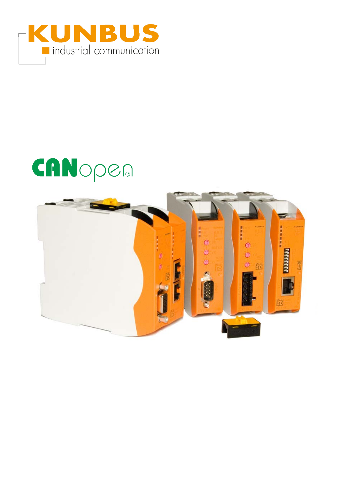
User Manual
Gateway component for CANopen
PR100070 • 03/09/2015

Table of Contents KUNBUS GmbH
Table of Contents
1 General information ........................................................................................................................3
1.1 Disclaimer..................................................................................................................................3
1.2 Notes regarding this user manual..............................................................................................4
1.3 Validity .......................................................................................................................................4
1.4 Limitation of Liability ..................................................................................................................4
1.5 Customer Service ......................................................................................................................4
2 Safe use ...........................................................................................................................................5
2.1 User ...........................................................................................................................................5
2.2 Symbols.....................................................................................................................................5
3 Overview ..........................................................................................................................................6
3.1 Functionality ..............................................................................................................................6
3.2 Control elements .......................................................................................................................7
3.3 Status LEDs.............................................................................................................................10
4 Installation .....................................................................................................................................11
4.1 Preparations for interference-free operation............................................................................11
4.2 Requirements .........................................................................................................................13
4.3 Connecting Gateway Components..........................................................................................14
4.4 Installing Gateway in the Control Cabinet ...............................................................................15
4.5 Connecting Power Supply .......................................................................................................16
4.6 Connecting Gateway to the Fieldbus.......................................................................................17
5 Configuration.................................................................................................................................18
5.1 Supported Size of the Process Data ......................................................................................18
5.2 Address Assignment................................................................................................................19
5.3 CANopen Configuration...........................................................................................................21
6 Technical data ...............................................................................................................................27
6.1 Technical data .........................................................................................................................27
ii Gateway component for CANopen

1 General information
1.1 Disclaimer
© 2015 KUNBUS GmbH, Denkendorf (Deutschland)
The contents of this user manual have been prepared by the
KUNBUS GmbH with the utmost care. Due to the technical
development, the KUNBUS GmbH reserves the right to change or
replace the contents of this user manual without prior notice. You can
always obtain the latest version of the user manual at our homepage:
www.kunbus.de
The KUNBUS GmbH shall be liable exclusively to the extent
specified in General Terms and Conditions (www.kunbus.de/
agb.html).
The contents published in this user manual are protected by
copyright. Any reproduction or use for the in-house requirements of
the user is permitted. Reproduction or use for other purposes are not
permitted without the express, written consent of the KUNBUS
GmbH. Contraventions shall result in compensation for damages.
General information
Trademark protection
– KUNBUS is a registered trademark of the KUNBUS GmbH
– Windows® and Microsoft® are registered trademarks of the Microsoft,
Corp.
– Modbus is a registered trademark of the Modbus-IDA Organization.
KUNBUS GmbH
Heerweg 15 c
73770 Denkendorf
Deutschland
www.kunbus.de
Gateway component for CANopen 3 / 28

1.2 Notes regarding this user manual
This user manual provides important technical information that can
enable you, as a user, to efficient, safe and convenient integration of
the Gateways into your applications and systems. It is intended for
trained, qualified personnel, whose sound knowledge in the field of
electronic circuits and expertise of CANopen is assumed.
As an integral part of the module, the information provided here
should be kept and made available to the user.
1.3 Validity
This document describes the application of the KUNBUS Gateways
with the product number:
– PR100070, Release 00
1.4 Limitation of Liability
Warranty and liability claims will lapse if:
General information
– the product has been used incorrectly,
– damage is due to non-observance of the operating manual,
– damage is caused by inadequately qualified personnel,
– damage is caused by technical modification to the product (e.g.
soldering).
1.5 Customer Service
If you have any questions or suggestions concerning this product,
please do not hesitate to contact us:
KUNBUS GmbH
Heerweg 15 C
+49 (0)711 3409 7077
support@kunbus.de
www.kunbus.de
Gateway component for CANopen
4 / 28

2 Safe use
2.1 User
The Gateway may only be assembled, installed and put into
operation by trained, qualified personnel. Before assembly, it is
absolutely essential that this documentation has been read carefully
and understood. Expertise in the following fields is assumed:
– Electronic circuits,
– Basic knowledge of CANopen,
– work in electrostatic protected areas,
– Locally applicable rules and regulations for occupational safety.
2.2 Symbols
The symbols used have the following meaning:
Safe use
DANGER
CAUTION
NOTICE
Hazard
Observe this information without fail!
There is a safety hazard that can lead to serious injuries and death.
Caution
There is a safety hazard that can result in minor injuries and material
damage.
Note
There is a safety hazard that can result in material damage.
Gateway component for CANopen 5 / 28
3 Overview
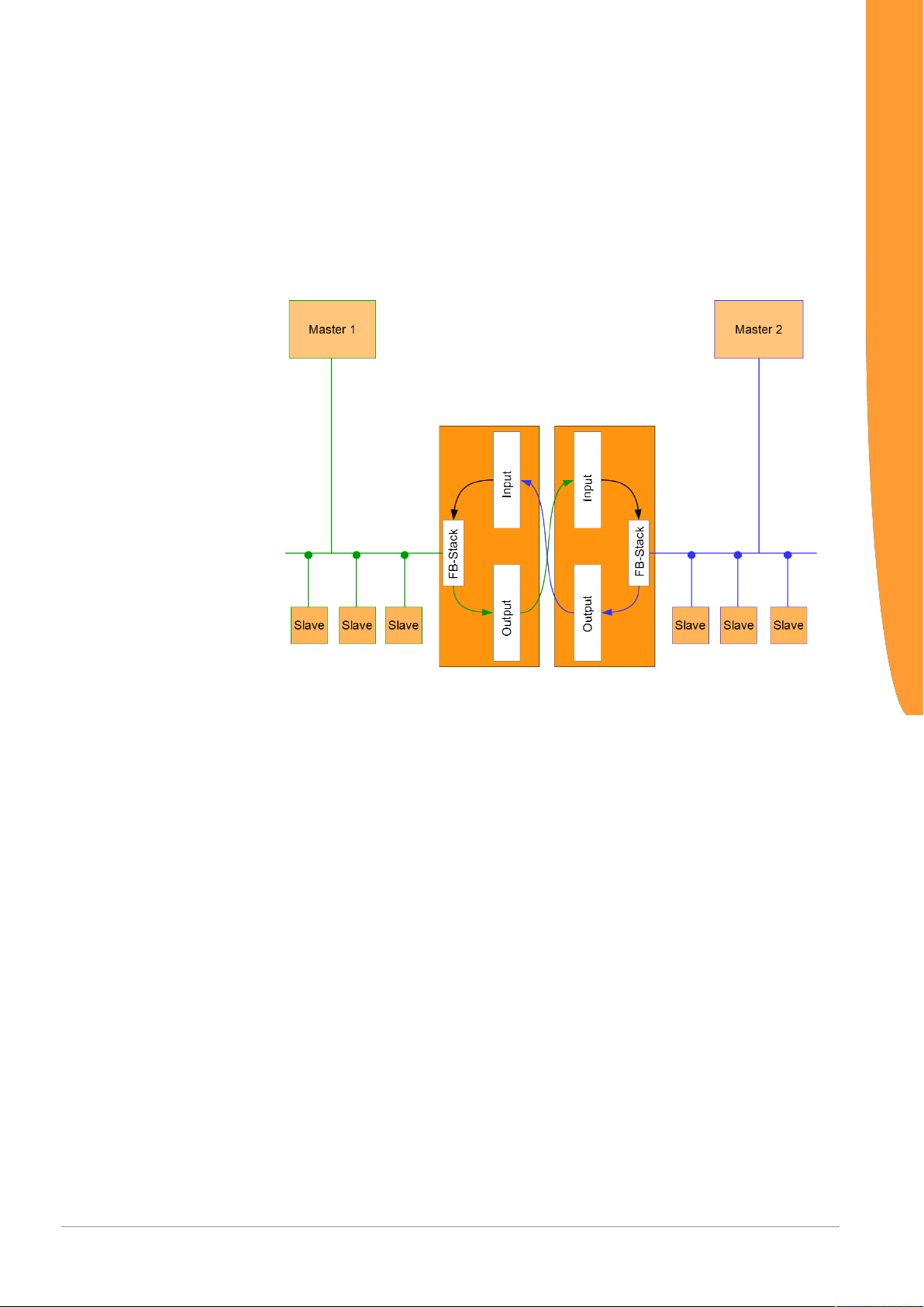
3.1 Functionality
The KUNBUS Gateway is a protocol converter. It allows
communication between networks with different protocols.
Overview
Illustration1: Functionality
A Gateway consists of 2 gateway components that master one
specific protocol each. You can combine these gateway components
as you wish. This design offers you a high degree of flexibility, since
you can exchange the individual gateway components at any time.
The following gateway components are available as slave at present:
– CANopen
– CC-Link
– DeviceNet
– EtherCAT
– EtherNet/IP
– Modbus RTU
– Modbus TCP
– POWERLINK
– PROFIBUS
– PROFINET
– Sercos III
Gateway component for CANopen
6 / 28
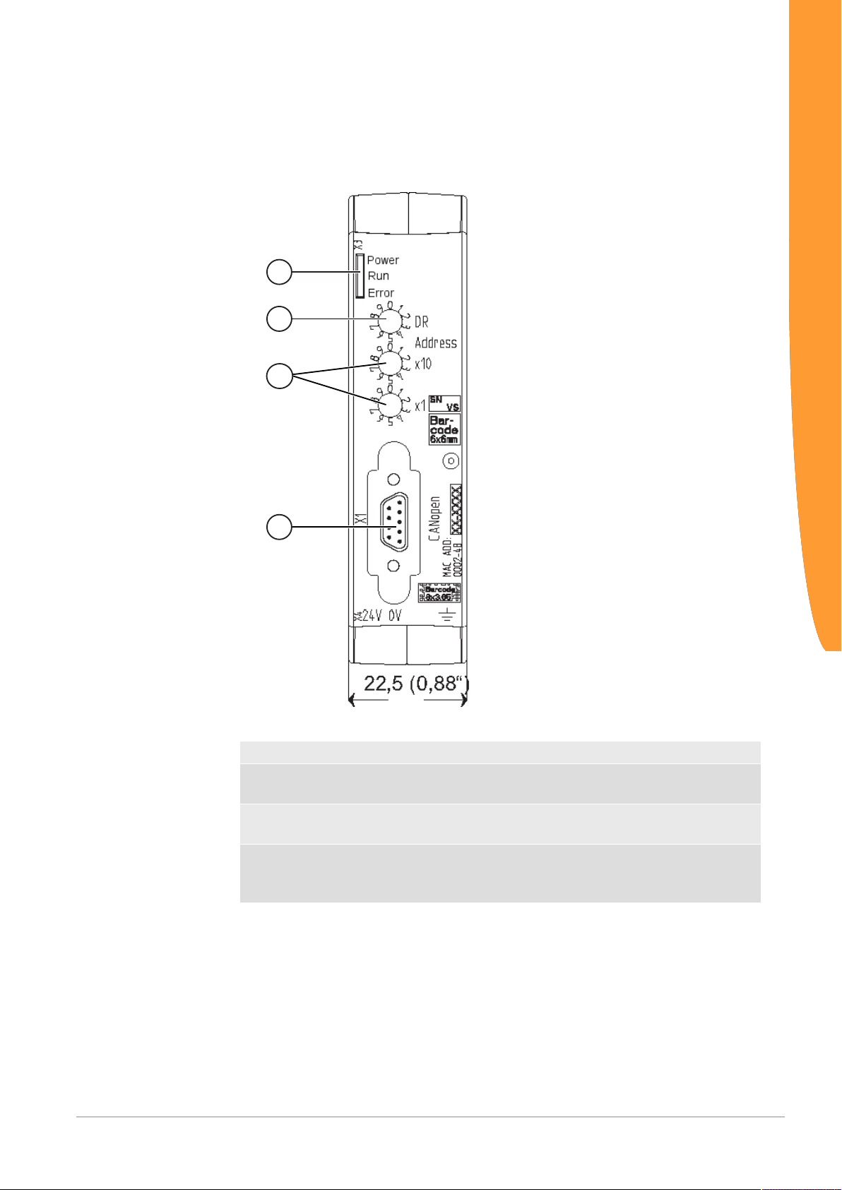
3.2 Control elements
1
2
3
4
Front view
Overview
Illustration2: Front view CANopen
1 Status LEDs
2 Rotary coding switch
for setting the bitrate
3 2 Rotary coding switches
for setting the node ID
4 Fieldbus connection
D-Sub-9 socket for the connection to
PROFIBUS.
Gateway component for CANopen 7 / 28
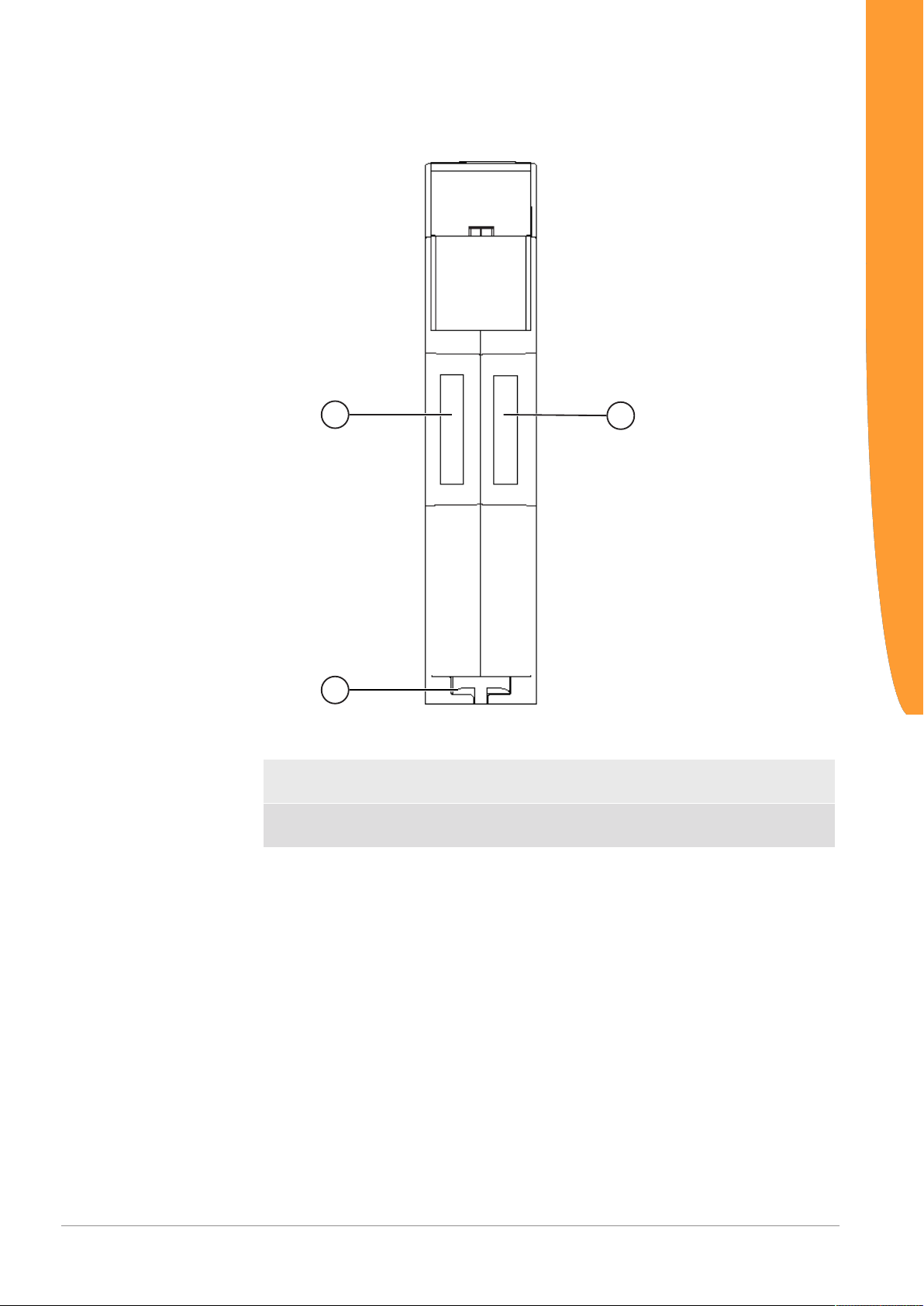
Top
1
1
2
Overview
Illustration3: Top
1 Interconnect Port
for interconnecting the gateway components.
2 Locking clamps
for securely attaching the gateway component to the DIN rail.
Gateway component for CANopen
8 / 28
Bottom
1
2
Overview
Illustration4: Bottom
1 Mains connection
with 24 V power supply
2 Locking clamps
for securely attaching the gateway component to the DIN rail.
Gateway component for CANopen 9 / 28

3.3 Status LEDs
The signals of the status LEDs for CANopen have the following
meaning:
LED Designation Signal Meaning
Power off Gateway not running
flashes, green Initialisation phase not yet completed
on, green Operational
flashes, red Correctable error (e.g. partner gateway
on, red Serious error/defect in the gateway
Run LED off Gateway component not running
on, green CANopen State: Operational
1 flash, green CANopen State: Stopped
flashes, green CANopen State: Preoperational
flickers, green CANopen: Automatic bitrate detection
Error LED off No Error
on, red CAN Controller is in Bus-Off State
1 flash, red CAN Controller has reached a Warning
2 flashes, red A Node Guard or Heartbeat event has
flickers, red CAN Automatic Baudrate Detection
Overview
component missing*)
or LSS node setting active
Limit
occurred
active or LSS Node setting active
* If this error occurs, an emergency object with the error code 90XXh
is sent. The error code is entered in the object 1003h (pre-defined
error field).
Gateway component for CANopen
10 / 28

4 Installation
4.1 Preparations for interference-free operation
In the following section we have compiled some general information
for you, which is important for interference-free operation. If you are
already acquainted with this topic, you can skip to the next section.
There, you will learn about which conditions are necessary for
installing the gateway.
Cable routing
Route your cables separately in cable groups. This will protect your
gateway from any unintended electromagnetic interferences.
The following groups should be routed separately:
Group Line
A Data and power supply lines for:
DC voltage below 60V
AC voltage below 25V
B Data and power supply lines for
DC voltage between 60V and 400V
AC voltage between 25 and 400V
C Power supply lines above 400V
Installation
– You can route cables of the same group together in cable ducts or
bundles.
– Cables of group A and B:
– Route the groups in separate bundles or
– in cable ducts at a minimum distance of 10 cm from each other.
– Cables of group C
– Route the groups in separate bundles or
– in cable ducts at a minimum distance of 50 cm from the other
groups.
Shielding
Shield your cables. This will reduce any unintended electromagnetic
interferences.
Gateway component for CANopen 11 / 28

Potential equalization
Potential differences occur when devices are connected to different
earths. These potential differences cause malfunctions.
To prevent malfunctions, you have to route an equipotential
equalization conductor.
When doing so, bear in mind the following points:
– Select an equipotential equalization conductor with low impedance.
– Select as a reference value for the cross-section of the potential
equalization cable:
– 16 mm2 for potential equalization cables of up to 200 m in length
– 25 mm2 for potential equalization cables of more than 200 m in
length
– Use potential equalization cables made from copper or galvanized steel.
– Connect potential equalization cables extensively with the earth rail.
– The smallest surfaces as possible should be sandwiched between
potential equalization cables and signal cables.
If the devices of the control system are connected by shielded signal
cables that are earthed on both sides, the impedance must be 10%
of the shielding impedance.
Installation
Gateway component for CANopen
12 / 28

4.2 Requirements
The Gateway was designed for use in a control cabinet.
NOTICE
ü The protection class of the control cabinet must be equivalent to at least
IP54.
ü For installation in the control cabinet you need a DIN rail 35 x 7.5mm
(EN50022).
◦ Install the DIN rail horizontally in the control cabinet according to the
manufacturers' specifications. When doing so, make sure that the
Gateway is at a sufficient distance from other devices.
Your gateway could get damaged if temperatures are too high.
èMake sure that the ambient temperature in the control cabinet is less
than 60°C.
èKeep the ventilation slots unobstructed. These must not be covered by
cables etc.
èMaintain sufficient distance from other devices.
Installation
Illustration5: Distances for installation
◦ Connect each gateway component individually to functional earth.
When doing so, make sure that both voltages have the same ground.
ð Your control cabinet now meets all requirements for installing the
gateway.
Gateway component for CANopen 13 / 28

4.3 Connecting Gateway Components
In order to attain a fully functional gateway, you have to interconnect
both gateway components.
◦ Connect an interconnect port to each gateway component using the
plug-in jumper (product number PR100204).
◦
Installation
Illustration6: Connecting Gateway Components
Only ever interconnect 2 gateway components.
NOTICE
If you connect additional components, severe defects could result on all
devices.
Gateway component for CANopen
ð You can now install the gateway in the control cabinet.
14 / 28

4.4 Installing Gateway in the Control Cabinet
◦ Hold the raster element of the gateway on the DIN rail.
◦ Press down the locking elements towards the gateway.
◦ Make sure that the gateway is firmly attached to the DIN rail.
Installation
Gateway component for CANopen 15 / 28

4.5 Connecting Power Supply
3
1
2
4
To connect the gateway component to the power supply, you need a
spring-loaded terminal (e.g. Metz-Connect SP995xxVBNC).
You have to connect each gateway component separately to a power
supply. Never interconnect functional earth and GND, otherwise the
galvanic isolation between gateway GND and fieldbus ground will be
removed. Instead, connect the functional earth with low impedance to
the potential equalization. You can then dispense with this
connection if the shield of the fieldbus cable is connected to the
potential equalisation with lower impedance when entering the
control cabinet.
Installation
NOTICE
Use the same power supply for both gateway components.
Different power supplies could cause a defect on both module components
and malfunctions.
èEnsure in particular that no potential differences occur between the
GND pins (2).
Pin Assignment:
Pin Assignment
1 24V for module supply
2 GND
3 Do not connect!
4 Functional earth
NOTICE
Gateway component for CANopen
Do not connect GND to PE
This connection could cause unintended malfunctions.
16 / 28

4.6 Connecting Gateway to the Fieldbus
To connect the gateway component to CANopen, you need one
D-SUB9 connector.
The pin assignment complies with the specifications of the CiA.
Pin Signal Description
1 - Do not connect!
2 CAN_L
3 CAN_GND Data transmission potential
earth (galvanically isolated)
4 - Do not connect!
5 CAN_SHLD
6 - Do not connect!
7 CAN_H
8 Do not connect!
9 - Do not connect!
Installation
Gateway component for CANopen 17 / 28

5 Configuration
5.1 Supported Size of the Process Data
NOTICE
The gateway component for CANopen supports process data of a
length up to 512 bytes.
Bear in mind that the maximum length of the process data is always
determined by the fieldbus with the shorter data length.
Example:
CANopen supports 512 bytes
PROFIBUS supports 488 bytes
In conjunction with PROFIBUS/ CANopen this means that 488 bytes
are transmitted and updated cyclically.
Configuration
Gateway component for CANopen
18 / 28

Setting Node ID using the
1
2
3
rotary coding switch
5.2 Address Assignment
You have 2 different options for setting the node ID and bitrate for
communication with CANopen.
– Using the rotary coding switch
– Using the software of the CANopen Master (LSS)
Setting Node ID and Bitrate using the rotary coding switch
You can set the station address of the gateway component using the
rotary switches x10 and x1.
The address is assigned in decimal format. Thus, you have a value
range from 1-98 at your disposal.
With the two rotary switches you form a two-digit decimal number, in
which switch x10 (2) determines the tens digit and switch x1 (3)
determines the single digit.
Configuration
Illustration7: Coding switch
Gateway component for CANopen 19 / 28
Example: You want to set the value 39.
Setting for switch x10= 3
Setting for switch x 1 = 9

The settings execute the following actions:
Switch setting Action
"01" to "98" Setting the node ID
"00" Address assignment via LSS tele-
gram
"99" Firmware Reset
Info! The new node ID is first used when you restart the gateway
component.
Configuration
Setting Bitrate using the
Rotary Coding Switch
You can set the bitrate of the gateway component using the rotary
switch DR (1).
Values:
0: Automatic bitrate detection
1 10 Kbit/s
2: 20 Kbit/s
3: 50 Kbit/s
4: 125 Kbit/s
5: 250 Kbit/s
6: 500 Kbit/s
7: 800 Kbit/s
8: 1000 Kbit/s
9 LSS. Bitrate is set by LSS master
Setting Node-ID and Bitrate using the CANopen Master
The gateway component supports LSS. You can set the node ID
and/or bitrate using software of your CANopen Master and save it
permanently by LSS.
Setting the node ID using
LSS
Setting Bitrate using LSS
Gateway component for CANopen
◦ Set the switch "Node ID x 10" and switch Node ID x 1 to 0
◦ Assign a node ID for the gateway component in the master software of
your CANopen Master.
◦ Set the switch "Data Rate Selection" to 9
◦ Assign a bitrate for the gateway component in the master software of
your CANopen Master.
20 / 28

5.3 CANopen Configuration
To configure the gateway component, you have to perform the
appropriate settings in the standard objects with the configuration
software of your CANopen Master.
You can structure process data exchanged between the gateways
application-specifically on the CANopen side using the process data
object. For this purpose, CANopen uses mapping objects addressed
via index and subindex
The gateway component supports the objects listed below. They
comply with the specification DS302 (Version 4.02) of the CiA.
Configuration
Index Object Name Sub-
index
1000h Device Type 00h Device Type U32 RO 0000 0000h (No profile)
1001h Error register 00h Error register U8 RO
1003h Pre-defined error
field
1005h COB-ID Sync 00h COB-ID Sync U32 RW Default value is 0000 0080h
1006h Communication
cycle period
1008h Manufacturer
device name
1009h Manufacturer
hardware version
100Ah Manufacturer
software version
100Ch Guard time 00h Guard time U16 RW
100Dh Life time factor 00h Life time factor U8 RW
1010h Store
Parameters
1011h Restore
parameters
1014h COB ID EMCY 00h COB ID EMCY U32 RO Default value is 80h + Node ID
1015h Inhibit Time
EMCY
1016h Consumer
Heartbeat Time
1017h Producer
Heartbeat Time
1018h Identity object 00h Number of entries U8 RO 04h
00h Number of errors U8 RW
01h...
08h
00h Defines the sync interval U32 RW Default value is 0000 0000h
00h Manufacturer device name Visible
00h Manufacturer hardware version Visible
00h Manufacturer software version Visible
00h Largest sub index supported U8 RO 01h
01h Save all parameters U32 RW Baud rate and node ID cannot be
00h Largest sub index supported U8 RO 01h
01h Restore all default parameters U32 RW
00h Inhibit Time EMCY U16 RW Default value is 0000h
00h Number of entries U8 RO 01h
01h Consumer Heartbeat Time U32 RW Node ID + Heartbeat Time.
00h Producer Heartbeat Time U16 RW Default value is 0000h
01h Vendor ID U32 RO 000002D5h
02h Product Code U32 RO 71
03h Revision Number U32 RO 00010000h
04h Serial Number U32 RO
Description Data Type Access Comment
Error field U32 RO
RO "KUNBUS-GW CANopen"
string
RO 1.0
string
RO 1.0
string
stored using this command.
Value must be a multiple of 1ms.
Default value is 0000h
Gateway component for CANopen 21 / 28

1400h
...
1407h
1600h
...
1607h
1800h
...
1807h
1A00h
...
1A07h
Table1: Extract from the specification DS302 (Version 4.02)
Receive PDO
parameter
Receive PDO
mapping
Transmit PDO
parameter
Transmit PDO
mapping
00h Largest sub-index supported U8 RO 02h
01h COB ID used by PDO U32 RW
02h Transmission type U8 RW
00h No. of mapped application
objects in PDO
01h Mapped object #1 U32 RW
02h Mapped object #2 U32 RW
03h Mapped object #3 U32 RW
04h Mapped object #4 U32 RW
05h Mapped object #5 U32 RW
06h Mapped object #6 U32 RW
07h Mapped object #7 U32 RW
08h Mapped object #8 U32 RW
00h Largest sub-index supported U8 RO 05h
01h COB ID used by PDO U32 RW
02h Transmission type U8 RW
03h Inhibit Time EMCY U16 RW
05h Event Timer (ms) U16 RW
00h No. of mapped application
objects in PDO
01h Mapped object #1 U32 RW
02h Mapped object #2 U32 RW
03h Mapped object #3 U32 RW
04h Mapped object #4 U32 RW
05h Mapped object #5 U32 RW
06h Mapped object #6 U32 RW
07h Mapped object #7 U32 RW
08h Mapped object #8 U32 RW
U8 RW
Configuration
U8 RW
Gateway component for CANopen
22 / 28

Fieldbus Output Data (Direction Master)
With these objects you can read process data that the gateway
component sends to the Master. You have 3 possible access types:
– Byte
– Word
– Doubleword
Configuration
Index Object Name Sub-
index
2000h Output Buffer 00h Number of entries U8 RO Access type: Byte
01h Output Buffer Byte #0 U8 RO
02h Output Buffer Byte #1
... ...
80h Output Buffer Byte #127
2001h Output Buffer 00h Number of entries U8 RO
01h Output Buffer Byte #128 U8 RO
02h Output Buffer Byte #129
... ...
80h Output Buffer Byte #255
2002h Output Buffer 00h Number of entries U8 RO
01h Output Buffer Byte #256 U8 RO
02h Output Buffer Byte #257
... ...
80h Output Buffer Byte #383
2003h Output Buffer 00h Number of entries U8 RO
01h Output Buffer Byte #384 U8 RO
02h Output Buffer Byte #385
... ...
80h Output Buffer Byte #511
Description Data Type Access Remark
2010h Output Buffer 00h Number of entries U8 RO Access type: Word
01h Output Buffer Word #0 U16 RO
02h Output Buffer Word #1
... ...
40h Output Buffer Word #63
2011h Output Buffer 00h Number of entries U8 RO
01h Output Buffer Word #64 U16 RO
02h Output Buffer Word #65
... ...
40h Output Buffer Word #127
2012h Output Buffer 00h Number of entries U8 RO Access type: Word
01h Output Buffer Word #128 U16 RO
02h Output Buffer Word #129
... ...
40h Output Buffer Word #191
2013h Output Buffer 00h Number of entries U8 RO
01h Output Buffer Word #192 U16 RO
02h Output Buffer Word #193
... ...
40h Output Buffer Word #255
Gateway component for CANopen 23 / 28

2020h Output Buffer 00h Number of entries U8 RO Access type: Doubleword
01h Output Buffer DWord #0 U32 RO
02h Output Buffer DWord #1
... ...
20h Output Buffer DWord #31
2021h Output Buffer 00h Number of entries U8 RO
01h Output Buffer DWord #32 U32 RO
02h Output Buffer DWord #33
... ...
20h Output Buffer DWord #63
2022h Output Buffer 00h Number of entries U8 RO Access type: Doubleword
01h Output Buffer DWord #64 U32 RO
02h Output Buffer DWord #65
... ...
20h Output Buffer DWord #95
2023h Output Buffer 00h Number of entries U8 RO
01h Output Buffer DWord #96 U32 RO
02h Output Buffer DWord #97
... ...
20h Output Buffer DWord #127
Configuration
2200h Properties of the
partner gateway
component
00h Number of entries U8 RO
01h Input size U16 RO
02h Output size U16 RO
03h Module type U16 RO 71
04h Fieldbus state U8 RO s. Table Fieldbus Status
Value Meaning
0x00 Fieldbus not connected. Check all connections
0x01 Fieldbus connected, no data communication. Check whether a node ID is
set
0x02 Gateway component configured, no data communication
0x03 Cyclical data exchange
Table2: Fieldbus status
Gateway component for CANopen
24 / 28

Fieldbus Input Data (from the Master)
With these objects you can read process data that the CANopenMaster sends to the gateway component. You have 3 possible
access types:
– Byte
– Word
– Doubleword
Index Object Name Su-
2100h Input Buffer 00h Number of entries U8 RO Access type: Byte
2101h Input Buffer 00h Number of entries U8 RO
2102h Input Buffer 00h Number of entries U8 RO Access type: Byte
2103h Input Buffer 00h Number of entries U8 RO
Description Data Type Access Comment
binde
x
01h Input Buffer Byte #0 U8 RO
02h Input Buffer Byte #1
... ...
80h Input Buffer Byte #127
01h Input Buffer Byte #128 U8 RO
02h Input Buffer Byte #129
... ...
80h Input Buffer Byte #255
01h Input Buffer Byte #256 U8 RO
02h Input Buffer Byte #257
... ...
80h Input Buffer Byte #383
01h Input Buffer Byte #384 U8 RO
02h Input Buffer Byte #385
... ...
80h Input Buffer Byte #511
Configuration
2110h Input Buffer 00h Number of entries U8 RO Access type: Word
01h Input Buffer Word #0 U16 RO
02h Input Buffer Word #1
... ...
40h Input Buffer Word #63
2111h Input Buffer 00h Number of entries U8 RO
01h Input Buffer Word #64 U16 RO
02h Input Buffer Word #65
... ...
40h Input Buffer Word #127
Gateway component for CANopen 25 / 28

2112h Input Buffer 00h Number of entries U8 RO Access type: Word
01h Input Buffer Word #128 U16 RO
02h Input Buffer Word #129
... ...
40h Input Buffer Word #191
2113h Input Buffer 00h Number of entries U8 RO
01h Input Buffer Word #192 U16 RO
02h Input Buffer Word #193
... ...
40h Input Buffer Word #255
2120h Input Buffer 00h Number of entries U8 RO Access type: Doubleword
01h Input Buffer DWord #0 U32 RO
02h Input Buffer DWord #1
... ...
20h Input Buffer DWord #31
2121h Input Buffer 00h Number of entries U8 RO
01h Input Buffer DWord #32 U32 RO
02h Input Buffer DWord #33
... ...
20h Input Buffer DWord #63
2122h Input Buffer 00h Number of entries U8 RO Access type: Doubleword
01h Input Buffer DWord #64 U32 RO
02h Input Buffer DWord #65
... ...
20h Input Buffer DWord #95
2123h Input Buffer 00h Number of entries U8 RO
01h Input Buffer DWord #96 U32 RO
02h Input Buffer DWord #97
... ...
20h Input Buffer DWord #127
Configuration
Gateway component for CANopen
26 / 28

6 Technical data
6.1 Technical data
Dimensions
Width 22.5 mm
Height 96 mm
Depth 110.4 mm
Weight 90 g
Electrical Data
Power supply 24 V
Power consumption during operation
(cyclical data exchange)
Status display LED
Environmental Conditions
Ambient temperature 0 – 60 °C
Storage temperature - 25 – 70 °C
Humidity 93 % (at 40 °C)
Condensing Not allowed
Protection class
Control cabinet
Housing
Terminal area
100mA
IP54
IP20
IP20
Technical data
Assembly Data
DIN rail 35 x 7.5 mm
Height 96 mm
Depth 110.4 mm
CANopen Interface
Device Type Slave
Station address 1-98 (decimal)
Input data
Output data
Gateway component for CANopen 27 / 28
512 byte
512 byte

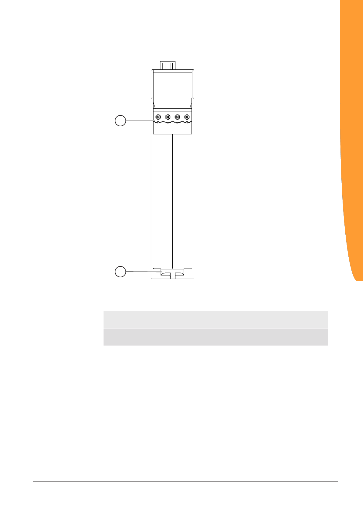
Illustration8: Side dimensions
Technical data
Illustration9: Front dimensions
Gateway component for CANopen
28 / 28
 Loading...