


 Loading...
TRUCK PARTS MANUAL
FOR VERTICAL MIXER MODELS
5032, 5042 and 5055
Table of Contents |
|
Abbreviations .................................................................................................. |
2 |
Using This Service Parts Listing ..................................................................... |
3 |
Body and Fender Parts................................................................................... |
4 |
Mounting Parts ............................................................................................... |
4 |
Right Angle Gearbox Drive Parts ..................................................................... |
5 |
Gearbox Input and Pinion Gear Drive Parts ..................................................... |
5 |
Auger Drive and Tower Assembly Parts - 5032, 5042 and 5055 ....................... |
6 |
Auger Drive and Tower Assembly Parts - 5042 and 5055 ................................ |
8 |
Auger Assembly Parts - 5032 ....................................................................... |
10 |
Auger Assembly Parts - 5042 ........................................................................ |
11 |
Auger Assembly Parts - 5055 ....................................................................... |
12 |
Door and Cylinder Parts - 5032, 5042 and 5055 ............................................ |
13 |
Door and Cylinder Parts - 5042 and 5055 ..................................................... |
14 |
Slide Tray ..................................................................................................... |
15 |
PTO Driveline (1000 RPM - 6 - Spline - 1 3/8 Yoke) ...................................... |
16 |
Gearbox Parts (Comer 4.25:1) ...................................................................... |
17 |
Right Angle Gearbox (3 Shaft) (Superior Gearbox Co.) ................................. |
18 |
Hydraulic Pump Kit - 12 Volt ........................................................................ |
20 |
Hydraulic Pump and Valve Schematic .......................................................... |
21 |
Indicator Mount and Joystick Controls .......................................................... |
23 |
Scale Parts .................................................................................................. |
24 |
Side Extensions and Hay Retention Options ................................................ |
26 |
Decal and Paint List ..................................................................................... |
27 |
Hardware Part Number Listing ...................................................................... |
28 |
Part Number Index ....................................................................................... |
30 |
Catalog Part Number 005945 Unit Serial Number_____________
Operator Instruction Manual for this unit: 005908
© Copyright 2004 Kuhn Knight, Inc.
5032/5042/5055TK 005945 R070804
Abbreviations
Assy ................................................ |
|
Assembly |
A/R .............................................. |
|
As Required |
B ............................................................... |
|
Bolt |
Brg ...................................................... |
|
Bearing |
BSN ............................... |
|
Before Serial Number |
Btm ...................................................... |
|
Bottom |
C-Bolt ......................................... |
|
Carriage Bolt |
Cttr......................................................... |
|
Cotter |
CV ....................................... |
|
Constant Velocity |
Deg ...................................................... |
|
Degree |
Dia .................................................... |
|
Diameter |
ea ........................................................... |
|
Each |
eq or Equiv ...................................... |
|
Equivalent |
Fln ....................................... |
|
Flanged Lock Nut |
Fw ................................................ |
|
Flat Washer |
Ga ......................................................... |
|
Gauge |
Gr or Grd ................................................ |
|
Grade |
Hd ........................................................... |
|
Head |
Hfw..................................... |
|
Heavy Flat Washer |
Hyd ................................................... |
|
Hydraulic |
ID ............................................ |
|
Inside Diameter |
Ill or Illus ......................................... |
|
Illustration |
Ind ...................................................... |
|
Indicator |
Jn ....................................................... |
|
Jam Nut |
Kw ...................................................... |
|
Keyway |
LH ..................................................... |
|
Left Hand |
Ln ..................................................... |
|
Lock Nut |
Lw ............................................... |
|
Lock Washer |
Mtg Hrd .............................. |
|
Mounting Hardware |
NC .......................................... |
|
National Coarse |
NF ............................................... |
|
National Fine |
NLA .................................. |
|
No LongerAvailable |
NPT ................................ |
|
National Pipe Thread |
OD ....................................... |
|
Outside Diameter |
Pc(s) .................................................. |
|
Piece(s) |
PD ........................................... |
|
Pitch Diameter |
PTO ................................ |
|
Power Takeoff (shaft) |
Qty..................................................... |
|
Quantity |
RH ................................................. |
|
Right Hand |
SN ............................................ |
|
Serial Number |
SHCS ....................... |
|
Socket Head Cap Screw |
Spk, or Spkt or Sprkt |
.......................... Sprocket |
|
Sq ........................................................ |
|
Square |
SS ........................................... |
|
Stainless Steel |
SSB .................................. |
|
Stainless Steel Bolt |
St ........................................................ |
|
Straight |
Std ..................................................... |
|
Standard |
STS ................................... |
|
Self Tapping Screw |
UASN ...................... |
|
Used After Serial Number |
UBSN ................... |
Used Before Serial Number |
|
W ............................................................. |
|
With |
W/O .................................................. |
|
With Out |
2 |
© Copyright 2004 Kuhn Knight, Inc. |
Using This Service Parts Listing
This listing uses a number indentation system to specify the parts of an assembly. Any number which is indented to the right, indicates that it is a component of the item to the upper left. Example:
Part no |
Qty |
Description |
102-AAA |
# |
Assembly A |
102-BBB |
# |
Sub-Assembly B |
(Component of A) |
|
|
140-xxx |
# |
Sub-Component of B |
140-xxx |
# |
Sub-Component of B |
102-CCC |
# |
Sub-Assembly C |
(Component of A) etc.
Using this system, the subassemblies and their components are included if an Assembly is ordered.
Similarly, the components of a subassemblies are included if a subassembly is ordered.
The quantity (Qty) associated with an assembly, represents the number of times an assembly could be shown in the drawing. The subassembly quantity however, is the number of times a subassembly is used to build one assembly. Similarly, the component quantity refers to the number of times a given component is found in one subassembly.
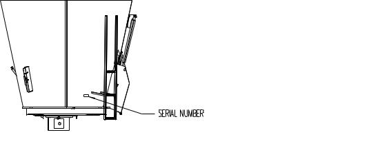
MODEL AND SERIAL NUMBER INFORMATION is located near the front left hand corner (Fig. A). The model number, serial number and part number should be known when asking service personnel for parts.
5032/5042/5055TK 005945R 070804
The serial number may consist of a number, or a number with a letter prefix. When referring to serial number breaks in the text of this manual, a serial number with a prefix will have been manufactured after a serial number without a prefix (A001 made after 0123). Likewise, a higher prefix letter would indicate manufacture after a lower prefix letter (B001 made after A123). Therefore, if the text refers to units manufactured after serial number B123, this would include “B” series numbers greater than 123, and all numbers with a higher letter prefix.
If you cannot find the part you need, be as descriptive as possible when placing an order:
Sprockets: give the bore size, number of teeth, and size of keyway.
Roller chain: give the size of chain (stamped on the side of each link) and number of links.
Shafting: give the diameter, length, and quantity and size of keyways.
Hardware is generally not included with parts. If you need any hardware, check the size, the length, and the grade (Fig. B), then check the hardware list in this manual for the part numbers.
All hex head bolts are grade 5, and nuts are grade 5 unless otherwise stated.
The hardware listing also includes zerks, cotter pins, set screws, and roller chain links.
The illustrations in this manual are meant to be used only as a guide for identifying parts and locating their relative positions.
Figure A
Kuhn Knight, Inc. |
3 |
1501 West 7th Ave., Brodhead, WI 53520 |
|
701 Cherry Ave., Greeley, CO 80632

5032/5042/5055TK 005945 R070804
Body and Fender Parts
REF |
PART NO |
QTY |
DESCRIPTION |
1 |
103-678 |
2 |
Haydog; Mtg. Hrd: 1/2” x 1 3/4”B, LN (1EA) |
2 |
174-765 |
2 |
Bent Hitch Pin, 1/2” DIA x 2 1/2” |
3 |
171-919 |
1 |
Drain Plug |
4 |
140-780 |
1 |
Dipstick |
5 |
103-920 |
4 |
Fender Mount, Poly; Mtg. Hrd: 1/2” x 2”B, LN Gr5 (2EA) |
6 |
175-206 |
2 |
Fender, Poly |
7 |
173-760 |
3 |
Mud Flap; Mtg Hrd: 5/16”x 1”B,FLN,3/8” Heavy FW (4EA) (front flap is half) |
8 |
175-204 |
8 |
Clamp |
Mounting Parts
REF |
PART NO |
QTY |
DESCRIPTION |
1 |
103-850 |
2 |
Weigh Bar Mount; Mtg Hrd: 3/4” x 5”Bolt,Lock Nut (4) |
2 |
103-845 |
4 |
Weigh BarSpool mount |
3 |
141-517* |
A/R |
Scale Mount Spacer; Mtg Hrd: 3/4” B (2ea), Heavy FW (4ea),LN (2ea) Grade 8 |
4 |
138-044 |
4 |
Sub-Frame Mount; Mtg Hrd: 3/4” x 2”Bolt, LN (8ea) Grade 8 |
5 |
140-775 |
1 |
Bumper; Mtg Hrd:1/2” x 1 3/4”B,FW,LW,NUT (4ea) |
6 |
103-730 |
2 |
Bumper Support Brace |
7 |
174-979 |
4 |
Weigh Bar; 2-7/8”; Mtg Hrd; 5/8” x 4-1/2” Bolt, Ln |
*Use 3/4” Gr8 Bolt, the length will be determined by thickness of the spacers being used. |
|||
4 |
|
|
© Copyright 2004 Kuhn Knight, Inc. |
5032/5042/5055TK 005945R 070804
Right Angle Gearbox Drive Parts
REF |
PART NO |
QTY |
DESCRIPTION |
1 |
173-366 |
1 |
Gearcase Assembly, 1.35:1;Mtg Hrd: 1/2” x 1”B,LW(4EA) |
2 |
173-046 |
1 |
Gearcase Assembly, 1.35:1 (3 shaft); Mtg Hrd: 1/2” x 1”B,LW (4EA) |
3 |
136-119 |
2 |
Sprocket, 1 3/8” Bore, 50-B-16 |
4 |
170-316 |
1 |
Chain, Roller, 50-2-16 |
5 |
170-627 |
3 |
Key, 5/16” SQ. x 1 3/4” |
6 |
136-174 |
1 |
Gearcase Mount |
7 |
140-677 |
1 |
Plate, 3/8” x 6-7/8” x 10” |
8 |
132-687 |
1 |
Torque Angle |
9 |
172-152 |
1 |
Key, 5/16” SQ. x 2 1/2” |
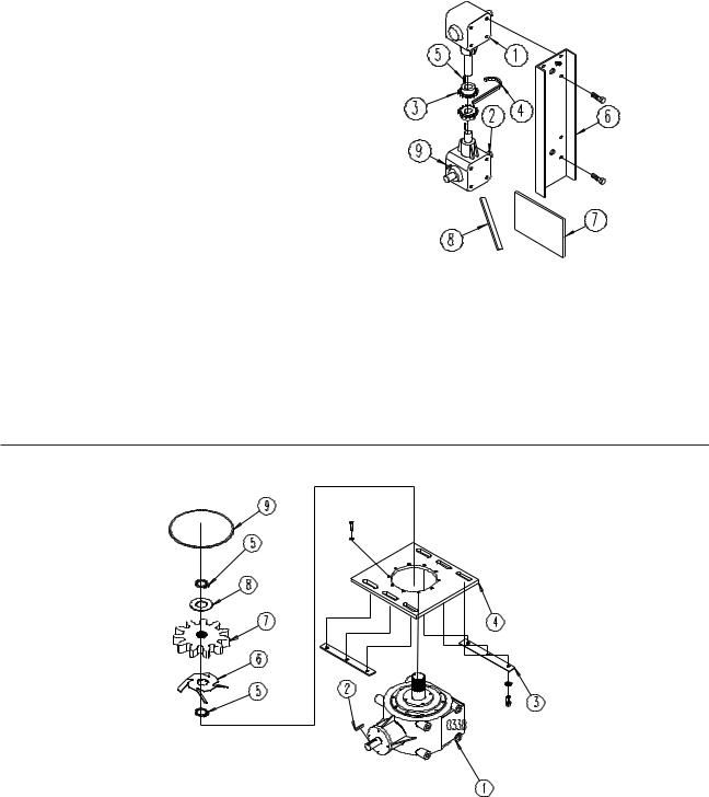
Gearbox Input and Pinion Gear Drive Parts
REF |
PART NO |
QTY |
DESCRIPTION |
1 |
174-873 |
1 |
Gearbox; 4 1/4:1 ratio, Mtg Hrd: (174-911) M12 x 45MM B(10EA) 5055 |
2 |
170-019 |
1 |
Key; 1/2” x 1/2” x 2” |
3 |
141-549 |
2 |
Gearbox Spacer |
4 |
140-955 |
1 |
Gearbox Mount; Mtg Hrd: 3/4” x 2”B,LW,(6EA) |
5 |
171-934 |
2 |
Snap Ring; 3” External, Waldes 5100 Series |
6 |
141-131 |
1 |
Oil Slinger; 3”ID, (weld on) |
7 |
141-285 |
1 |
Pinion Gear; 3” ID |
8 |
136-040 |
AR |
Thrust Ring; 10Ga x 4-1/4” |
|
172-367 |
AR |
Shim; 1/16” x 3” x 4 1/4” |
9 |
141-465 |
1 |
O-ring |
Kuhn Knight, Inc. |
5 |
1501 West 7th Ave., Brodhead, WI 53520 |
|
701 Cherry Ave., Greeley, CO 80632
5032/5042/5055TK 005945 R070804
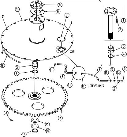
Auger Drive and Tower Assembly Parts - 5032, 5042 and 5055
Used on Units,Serial Number (5042-324 & 5055-116 and After)
REF |
PART NO |
QTY* |
DESCRIPTION |
1 |
103-936 |
1 |
Auger Drive Shaft; 4” Dia |
2 |
174-784 |
6 |
Stud, Wheel;3/4” x 3 1/8” |
3 |
141-594 |
2 |
Bearing, Plastic; 4”ID x 5” |
4 |
172-913 |
2 |
Quad-Ring Seal; 4”ID |
5 |
141-872 |
3 |
Thrust Washer |
6 |
141-666 |
1 |
Wear Plate |
7 |
141-671 |
1 |
Inspection cover; Mtg Hrd: 5/16” x 3/4” SSB (3EA) (5032) |
|
141-127 |
1 |
Inspection cover; Mtg Hrd: 5/16” x 3/4” SSB (3EA) (5042 & 5055) |
8 |
170-786** |
|
Copper Grease Line;(Front Upper Auger 87” Rear Upper Auger 99”) |
|
181-036**A |
|
Copper Grease Line;(Front Upper Auger 87“ Rear Upper Auger 99”) |
|
|
|
(Front Lower Auger 84“ Rear Lower Auger 96“)30’ 6” Total for unit. |
9 |
170-865 |
2 |
Grease Zerk 1/8” NPT |
10 |
172-024 |
3 |
Straight Adapter; 1/8” NPTF F x 1/8” NPTF F |
11 |
173-853 |
10 |
Straight Adapter; 3/16” Tube x 1/8” NPTF M |
12 |
174-762 |
2 |
Pipe Coupling; 1/8” STD NPT (weld on) |
13 |
170-244 |
2 |
Washer, 3/8” |
* : Quantity shown is for 1 Tower Assembly **: Sold By Linear Foot.
A: Used on units serial number 5032-167; 5042-93; 5055-38.
6 |
© Copyright 2004 Kuhn Knight, Inc. |
5032/5042/5055TK 005945R 070804
Auger Drive and Tower Assembly Parts - 5032, 5042 and 5055
Used on Units,Serial Number (5042-324 & 5055-116 and After)
REF |
PART NO |
QTY* |
DESCRIPTION |
14 |
104-022 |
1 |
Bull Gear (5032) |
|
103-858 |
1 |
Bull Gear (5042 & 5055) |
15 |
141-115 |
AR |
Shim (1/4”) |
|
141-116 |
AR |
Shim (1/16”) |
16 |
174-777 |
1 |
Washer; 3/16” x 7” x 4 1/16” ID |
17 |
171-989 |
1 |
Snap Ring; 4” External, Waldes 5100 series |
18 |
174-769 |
2 |
Magnet |
19 |
171-935 |
22’** |
Foam Rubber Seal; 3/8” x 3/4” |
20 |
103-934 |
1 |
Front Tower; Mtg Hrd: 174-767 Plow Bolt,5/8 x 2”, LN (17EA) (5032) |
|
103-935 |
1 |
Rear Tower; Mtg Hrd: 174-767 Plow Bolt,5/8 x 2”, LN (17EA) (5032) |
|
104-019 |
1 |
Front Tower; Mtg Hrd: 174-767 Plow Bolt,5/8 x 2”, LN (17EA) (5042,5055) |
|
104-020 |
1 |
Rear Tower; Mtg Hrd: 174-767 Plow Bolt,5/8 x 2”, LN (17EA) (5042,5055) |
21 |
174-807 |
2 |
Grommet, Rubber; 3/4” x 3/16” x 3/16”(Not Shown) |
* : Qty shown is for 1 Tower Assy. ** : Sold By Linear Foot.
Kuhn Knight, Inc. |
7 |
1501 West 7th Ave., Brodhead, WI 53520 |
|
701 Cherry Ave., Greeley, CO 80632

5032/5042/5055TK 005945 R070804
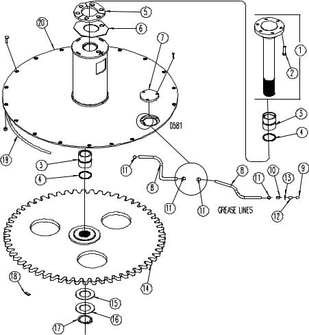
Auger Drive and Tower Assembly Parts - 5042 and 5055
Used on Units,Serial Number (5042-184 thru 5042-323 & 5055-115 and Before)
REF |
PART NO |
QTY* |
DESCRIPTION |
1 |
103-774 |
1 |
Auger Drive Shaft; 4” Dia |
2 |
174-784 |
6 |
Stud, Wheel;3/4” x 3 1/8” |
3 |
140-618 |
1 |
Thrust Washer, Nylon; 1/4” x 4.06”ID x 7”OD |
4 |
103-697B |
1 |
Thrust Plate |
5 |
135-692 |
2 |
Bearing, Plastic; 4”ID x 5” |
6 |
172-913 |
2 |
Quad-Ring Seal; 4”ID |
7 |
141-127 |
1 |
Inspection cover; Mtg Hrd: 5/16” x 3/4” SSB (3EA) |
8 |
140-722A |
2 |
Gear Guide,Top; Nylon: Mtg Hrd: 1/2” x 3 1/2” B,LN(2EA) |
9 |
180-786** |
|
Copper Grease Line;(Front Upper Auger 87“ Rear Upper Auger 99) |
|
|
|
(Front Lower Auger 84“ Rear Lower Auger 96“)30’ 6” Total for unit. |
|
181-036**C |
|
Copper Grease Line;(Front Upper Auger 87“ Rear Upper Auger 99) |
|
|
|
(Front Lower Auger 84“ Rear Lower Auger 96“)30’ 6” Total for unit. |
10 |
170-865 |
2 |
Grease Zerk 1/8” NPT |
11 |
172-024 |
3 |
Straight Adapter; 1/8” NPTF F x 1/8” NPTF F |
12 |
173-583 |
|
Straight Adapter |
|
172-822C |
10 |
Straight Adapter; 3/16” Tube x 1/8” NPTF M |
|
175-344 |
|
Grommet, Rubber |
|
174-807C |
2 |
Grommet, Rubber; 3/4” x 3/16” x 3/16”(Not Shown) |
13 |
174-762 |
2 |
Pipe Coupling; 1/8” STD NPT (weld on) |
14 |
170-244 |
2 |
Washer, 3/8” |
* : Quantity shown is for 1 Tower Assembly **: Sold By Linear Foot.
A : Used on serial number before (5042-200) or with laminated bullgears. B : Used on serial number before (5042-268 & 5055-78)
C : Used on serial number before (5032-167; 5042-93; 5055-38)
8 |
© Copyright 2004 Kuhn Knight, Inc. |

5032/5042/5055TK 005945R 070804
Auger Drive and Tower Assembly Parts - 5042 and 5055
Used on Units,Serial Number (5042-184 Thru 5042-323 & 5055-115 and Before)
REF |
PART NO |
QTY* |
DESCRIPTION |
15 |
181-048 |
24”** |
Stainless Steel Line; (12” EA) |
16 |
103-858 |
1 |
Bull Gear |
17 |
141-185A |
1 |
Gear Guide, Bottom; Nylon |
18 |
141-115 |
AR |
Shim (1/4”) |
|
141-116 |
AR |
Shim (1/16”) |
19 |
174-777 |
1 |
Washer; 3/16” x 7” x 4 1/16” ID |
20 |
171-989 |
1 |
Snap Ring; 4” External, Waldes 5100 series |
21 |
174-769 |
2 |
Magnet |
22 |
171-935 |
22’** |
Foam Rubber Seal; 3/8” x 3/4” |
23 |
103-775 |
1 |
Front Tower; Mtg Hrd: 174-767 Plow Bolt,5/8 x 2”, LN (17EA) |
|
103-776 |
1 |
Rear Tower; Mtg Hrd: 174-767 Plow Bolt,5/8 x 2”, LN (17EA) |
* : Qty shown is for 1 Tower Assy. ** : Sold By Linear Foot.
A : Used on units serial numbers (5042-184 Thru 5042-199) or with laminated bullgears.
Kuhn Knight, Inc. |
9 |
1501 West 7th Ave., Brodhead, WI 53520 |
|
701 Cherry Ave., Greeley, CO 80632
5032/5042/5055TK 005945 R070804
Auger Assembly Parts - 5032
REF |
PART NO |
QTY |
DESCRIPTION |
1 |
140-646 |
2 |
Auger Cover;Mtg hrd; 3/8” x 1 1/4” SSB(174-917), LW(2EA) |
2 |
103-933 |
2 |
Auger Assembly |
3 |
141-684 |
1 |
Top Flighting; 1/2” x 33” OD x 16” ID (weld on) |
4 |
141-016 |
1 |
Middle Flighting; 1/2” x 33” OD x 16” ID (weld on)(Actual Reqd’: 1/2 Piece) |
5 |
141-673 |
1 |
Lower Flighting; 1/2” x 65”OD x 16”ID (weld on) |
6 |
141-117 |
1 |
Filler Bar (weld on) |
7 |
141-380 |
1 |
Leading Edge (weld on) |
8 |
141-063 |
1 |
Sweeper Bar (weld on) |
9 |
141-134 |
1 |
Sweeper Brace Bar (weld on) |
10 |
141-019 |
1 |
Shark Tooth (weld on) |
11 |
141-955 |
1 |
Upper Flighting Brace (weld on) |
12 |
141-114 |
6 |
Knife; Mtg Hrd: 5/8” x 2” GRD5 C-bolt(175-110),FW,LN(170-031)(2EA)(8 MAX) |
13 |
141-406 |
4 |
Knife,Scallop; Mtg Hrd:1/2” x 1 1/2” GRD5 C-bolt(174-918), LN(170-042) (2EA) |
14 |
174-793 |
12 |
3/4” LW, External Tooth |
15 |
170-920 |
12 |
Nut, Wheel; 3/4” |
16 |
142-827 |
1 |
Flight Backer (Weld On) |
10 |
© Copyright 2004 Kuhn Knight, Inc. |
Loading...