


Reel AuggieReel Auggie
Reel Auggie
Reel AuggieReel Auggie
andand
and
andand
CommerCommer
Commer
CommerCommer
MixMix
Mix
MixMix
33
11
3
33
00 Ser00 Ser
1
00 Ser
11
00 Ser00 Ser
cial Rcial R
cial R
cial Rcial R
erer
er
erer
ss
s
ss
iesies
ies
iesies
eeleel
eel
eeleel
StationaryType
Operator’s Instruction Manual
Read this manual before operating the Reel Auggie or Commercial Reel Mixers.
Failure to follow instructions and safety precautions in this manual and in the
safety decals could result in severe injury or death.
Catalog #006046 01/05/07 supersedes 05/12/05
KUHN KNIGHT INC.
Corporate Headquarters 1501 West Seventh Avenue
Brodhead, WI 53520 Tel (608) 897-2131 Fax (608) 897-2561
www.kuhnknight.com

3100ST 006046 010507
TABLE OF CONTENTS
Introduction .................................................................................................................. 3
Using this Manual ...................................................................................................... 3
Safety ........................................................................................................................... 4
Understanding Safety Words and Symbols .............................................................. 4
Read the Operator’s Manual ..................................................................................... 4
Follow Safety Instructions and Precautions ..............................................................4
Operating Safety Precautions .................................................................................... 5
Safety Decals ............................................................................................................. 6
Safety ........................................................................................................................... 8
Safety Decal Placement ..........................................................................................10
Model 3115 S/N A0028 and before ........................................................................10
Model 3115 S/N A0029 and after ...........................................................................11
Model 3120 ............................................................................................................ 12
Models 3125 and 3130 ..........................................................................................13
Models 3150, 3160, 3170 and 3195 ..................................................................... 15
Mixer Setup ................................................................................................................ 16
Installation Tips ............................................................... ........................................ 16
Mixer Setup ................................................................................................................ 17
Safety Shields .......................................................................................................... 17
Auger Knives ............................................................................................................ 17
Reel Cross Tubes ...................................................................................................17
Mixer Setup ................................................................................................................ 18
Driveline Shear Bolts ............................................................................................... 18
Mixer test run ............................................................................................................18
Mixer Operation ..........................................................................................................19
General .................................................................................................................... 19
Safety ........................................................................................................................19
Limitations ............................................................................................................... 20
Warnings.................................................................................................................. 20
Mixing Time .............................................................................................................. 20
Material that can be Loaded Directly into the Mixer ................................................. 2 1
Materials Requiring Preparation ............................................................................. 21
Hay Quality ............................................................................................................... 21
Loading and Mixing ..................................................................................................22
Fill Level ...................................................................................................................23
Unloading ................................................................................................................23
Options ......................................................................................................................24
Door Flow Control Plates ........................................................................................24
Electric Door Control ................................................................................................24
Electronic Scales .....................................................................................................24
Hay Maxx System ................................................
Roughage Maxx System ..........................................................................................24
Inspections and Adjustments ................................................................................... 25
Inspect and Adjust... ................................................................................................ 25
Electronic Scales .....................................................................................................26
Hay Maxx System Adjustments ................................................................................27
Lubrication .................................................................................................................28
Lubrication Locations .............................................................................................. 28
3115 ....................................................................................................................... 28
3120 ....................................................................................................................... 29
3125 and 3130 .................................................. .....................................................30
3136, 3142, 3150, 3160, 3170 and 3195 ..............................................................31
Trouble Shooting ....................................................................................................... 32
Specifications 3115 to 3142 ...................................................................................... 35
Specifications 3150 to 3195 ...................................................................................... 36
..................................................... 24
2
© Copyright 2004 Kuhn Knight, Inc.
Back to Table of Contents
3100ST 006046 010507
INTRODUCTION
THANK YOU for purchasing a Kuhn Knight Reel Auggie or Commercial Reel. We appreciate your business.
You have purchased one of the best built, most reliable mixers available. We strive to provide you with a
rugged, durable unit which is simple to maintain. If you have suggestions for any of our products, please let us
know.
Kuhn Knight, Inc.
USING THIS MANUAL
This manual should be considered a permanent part of your machine, and should remain with the machine if
you sell it.
This manual has been designed to help you become familiar with your unit. A separate Parts Manual has been
provided for a detailed parts breakdown of the unit. Before you operate your unit, be sure you understand and follow
all the safety, operation and lubrication instructions on the following pages in this manual. These have been written
for your safety and convenience and to keep your unit running trouble-free for many years.
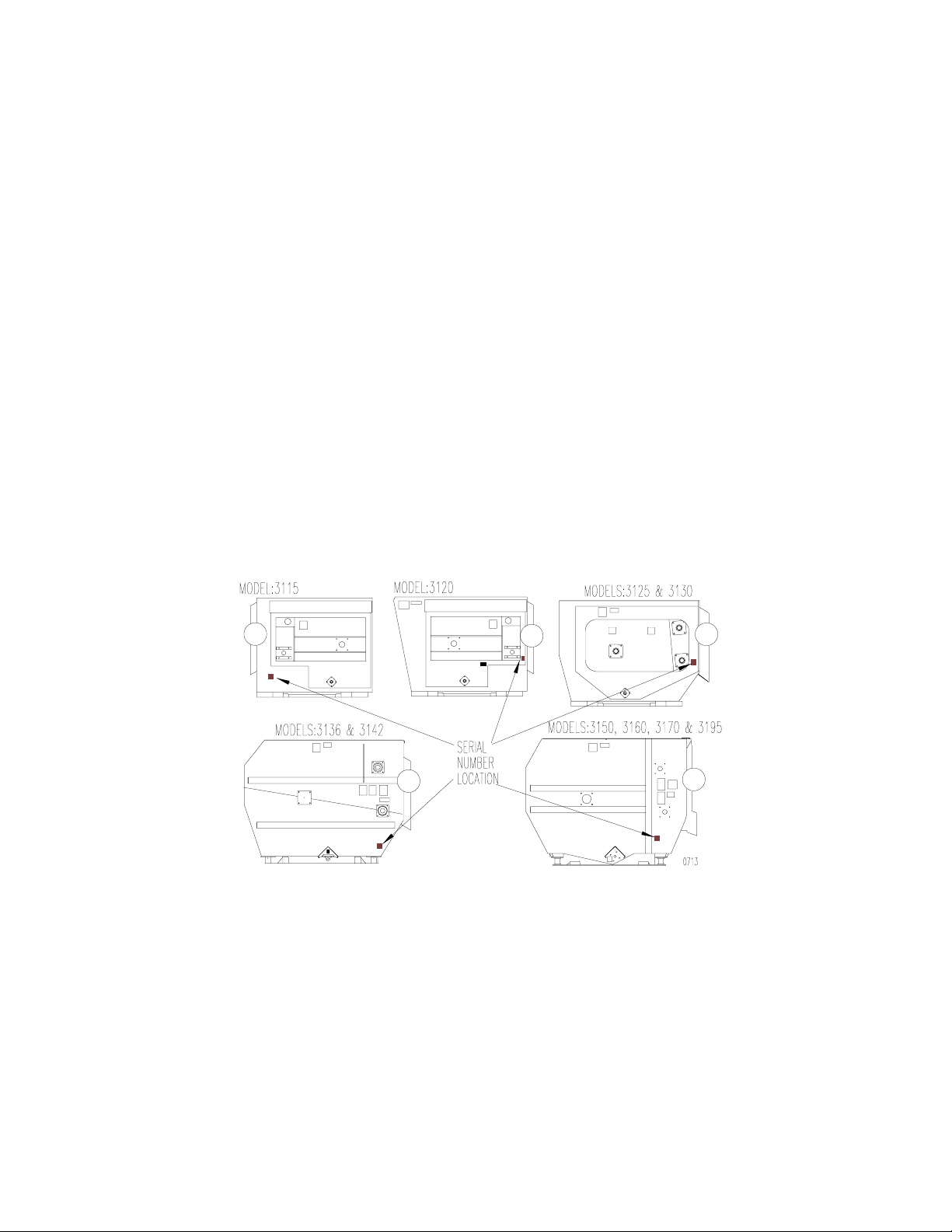
MODEL AND SERIAL NUMBER INFORMATION is located on the drive input end panel.
This is the number to give service personnel for parts and service questions.
ADDITIONAL MANUALS and safety decals may be obtained through your dealer, or by writing to the
address below.
Order Operator’s Manual # 006046 all stationary models
Order Parts Manual # 006049 for 3115 S/N A0028 and before
Order Parts Manual # 006050 for 3115 S/N A0029 and after
Order Parts Manual # 006051 for 3120
Order Parts Manual # 006054 for 3125 & 3130
Order Parts Manual # 006057 for 3136 & 3142
Order Parts Manual # 006060 for 3150, 3160, & 3170
Order Parts Manual # 006063 for 3195
Back to Table of Contents
1501 West 7th Ave., Brodhead, WI 53520
701 Cherry Ave., Greeley, CO 80632
Kuhn Knight, Inc.
3

3100ST 006046 010507
SAFETY
UNDERSTANDING SAFETY WORDS AND SYMBOLS
THIS SAFETY ALERT SYMBOL is used in this manual whenever personal safety is involved and
means ATTENTION! BECOME ALERT! It stresses an attitude of “HEADS UP” for safety. Read and
understand all pages in this manual that bear this safety symbol and . . . TAKE TIME TO BE
CAREFUL!
Each safety decal utilizes one of the signal words defined below and the color associated with each word.
DANGER: Indicates an imminently hazardous situation that, if not avoided, will result in death or serious
injury. It is denoted by the word DANGER, colored in white, on a red background.
WARNING: Indicates a potentially hazardous situation that, if not avoided, will result in death or serious
injury, and includes hazards that are exposed when guards are removed. It may also be used to alert against
unsafe practices. It is denoted by the word WARNING, colored in black, on an orange background.
CAUTION: Indicates a potentially hazardous situation that, if not avoided, may result in minor or moderate
injury. It may also be used to alert against unsafe practices. It is denoted by the word CAUTION, colored in
black, on a yellow background.
READ THE OPERATOR’S MANUAL
Any person who will be operating or maintaining this mixer should first read and understand this manual and all
safety warnings on the unit.
This instruction manual should always be available to those responsible for the operation and maintenance of this
mixer. It is the owner’s responsibility to provide this safety information to his or her operators and employees.
Any person who does not understand the safety and operation instructions contained in this manual should not be
considered qualified to operate this mixer.
FOLLOW SAFETY INSTRUCTIONS AND PRECAUTIONS
Specialized procedures and instructions are required and must be adhered to when working on this equipment.
Failure to follow the instructions contained in this manual could result in severe personal injury, death, and/or
product or property damage. All applicable safety procedures such as OSHA requirements, regional and local
safety codes and requirements, safe working practices, and good judgement must be used by personnel when
operating or maintaining this equipment.
4
© Copyright 2004 Kuhn Knight, Inc.
Back to Table of Contents

3100ST 006046 010507
SAFETY
OPERATING SAFETY PRECAUTIONS
When the mixer is in operation it has many moving parts which could cause severe injury or death to
persons coming in contact with these parts. To help avoid serious accidents, the following guidelines
should always be followed:
1. BE SURE ALL SAFETY SHIELDS are in place before operating, including driveline shields. Exposed
machinery due to missing shields can grab hands and clothing and cause severe injury or death.
Repair or replace any damaged or missing shields.
2. NEVER PUT ARMS OR FEET INSIDE unit or discharge door opening, nor climb on or in the mixer
while it is running. NEVER allow anyone to position themselves over or near the top of the mixer
while it is running. Rotating reel, augers, and sprockets can grab clothing or create pinch points which
can cause severe injury or death to the operator or bystanders. Always lock out the power so that the
mixer cannot be accidentally turned on while inspecting, servicing, repairing or cleaning mixer.
3. NEVER HAND FEED MATERIALS into mixer while it is running. Rotating reel and augers inside the
mixer may not be visible from the loading point, and may cut or grab hands, clothing or material being
loaded, causing severe injury. Always stop mixer and lock out the power before hand loading materials.
4. NEVER ATTEMPT TO RELEASE JAMMED MATERIALS OR CLEAN MATERIALS from any area of the
mixer or discharge chute without stopping mixer and locking out the power first. Moving parts
can be hidden by materials, and stopped parts can start unexpectedly, causing severe injury. Always stop
mixer and lock out the power before attempting to remove jammed material or to clean. Be aware that the
spring loaded reel arms can spring back unexpectedly, causing injury.
5. DO NOT ALLOW OPERATION of this unit by inexperienced and unqualified people. Keep all unqualified people away from mixer during operation. Operators of this unit must be alert and use good judgement
at all times. Operator should not climb on ladder or any part of the mixer when loading, mixing or
discharging material.
6. DO NOT wear loose or floppy clothing while operating this unit. Loose clothing may become entangled
in moving machinery.
7. BE SURE the inside of the mixer is clear of any obstructions and that all shields are in place before
operating. Repair or replace any damaged or missing shielding. Exposed sprockets and chains due to
missing shielding can grab hands and clothing and cause severe injury or death.
8. SHOULD A PROBLEM OCCUR during operation of mixer, always stop mixer and lock out the power
before investigating problem. If mixer power has not been locked out, the mixer may start unexpectedly,
causing severe injury or death.
9. USE CAUTION WHEN WORKING AROUND THE DISCHARGE AND HAY PAN AREA. Never reach into
discharge or hay pan area without first locking out power. Moving parts can be hidden by material, and
stopped parts can start unexpectedly, causing severe injury.
Back to Table of Contents
Kuhn Knight, Inc.
1501 West 7th Ave., Brodhead, WI 53520
701 Cherry Ave., Greeley, CO 80632
5

3100ST 006046 010507
SAFETY
SAFETY DECALS
Safety decals are placed on this unit for the protection of the operator or any person working on or
standing nearby the unit.
Everyone who operates or maintains the mixer must first read this manual and understand the meaning
of all safety decals. Contact your dealer if foreign language decals are required.
Keep safety decals clean and legible. If any are missing or illegible, contact your Kuhn Knight dealer or
Kuhn Knight to obtain replacements. The part numbers for the decals are located in the lower right corner of the
decal, and listed in this manual on the following pages. Replacement decals may be ordered through your dealer or
the address below.
Kuhn Knight, Inc.
1501 West 7th Ave., Brodhead, WI 53520
701 Cherry Ave., Greeley, CO 80632
Complete sets of decals (including information decals) can be ordered by using the following part numbers:
UNIT PART NO.
3115 70175433 S/N A0028 and before
3115 70175871 S/N A0029 and after
3120 70175436
3125 70175439
3130 70175442
3136 70175445
3142 70175448
3150 70175451
3160 70175454
3170 70175457
3195 70175460
When replacing decals, be sure the surface area is clean and dry, peel the backing off the decal, and apply to
the mixer. Be sure to wipe with a clean cloth to rub out all air bubbles to assure a good seal. For best adhesion
decals should be applied in temperatures of 50°F / 10°C or warmer.
6
© Copyright 2004 Kuhn Knight, Inc.
Back to Table of Contents
3100ST 006046 010507
SAFETY
SAFETY DECALS
Immediately replace all worn or damaged Safety Decals (listed on these pages). Please supply the unit’s
serial number with the order.
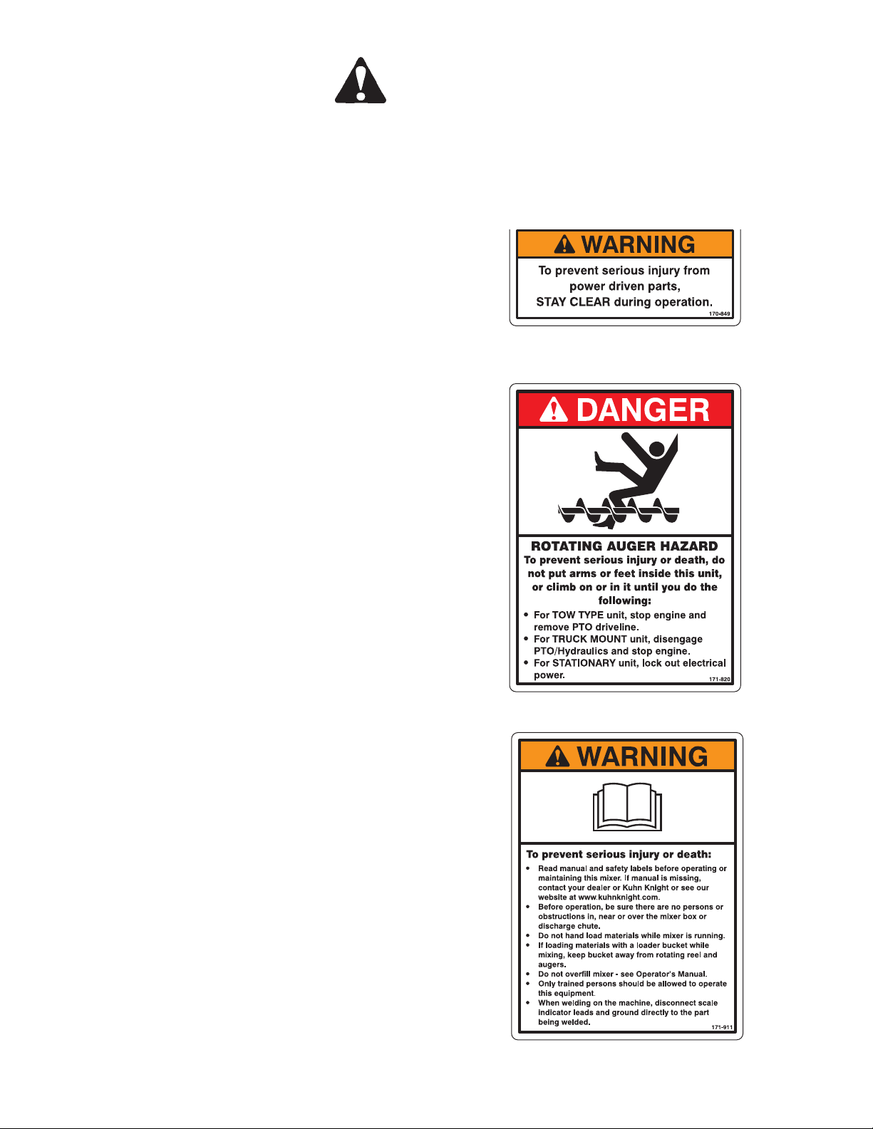
Figure A
WARNING, To prevent serious injury
Part Number 70170849
2 Required: 3115 & 3120 MODELS
2 Required: 3125 & 3130 MODELS
3 Required: 3136 & 3142 MODELS
3 Required: 3150, 3160, 3170 & 3195 MODELS
Figure B
DANGER, ROTATING AUGER HAZARD
Part Number 70171820
4 Required ALL MODELS
Figure C
WARNING, To prevent serious injury or death
Part Number 70171911
1 Required ALL MODELS
Back to Table of Contents
1501 West 7th Ave., Brodhead, WI 53520
701 Cherry Ave., Greeley, CO 80632
Kuhn Knight, Inc.
7
3100ST 006046 010507
SAFETY
SAFETY DECALS
Immediately replace all worn or damaged Safety Decals (listed on these pages). Please supply the unit’s
serial number with the order.
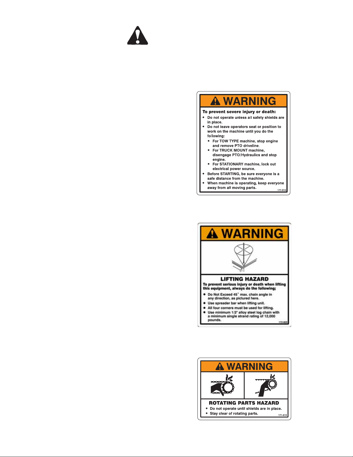
Figure D
WARNING, To prevent serious injury or death
SHIELDS ARE IN PLACE
Part Number 70171913
1 Required ALL MODELS
Figure E
WARNING, LIFTING HAZARD
Part Number 70172820
1 Required ALL MODELS
Figure F
WARNING, ROTATING PARTS HAZARD
Part Number 70171915
2 Required 3115 & 3120 MODELS
3 Required 3125 & 3130 MODELS
1 Required 3136, 3142, 3150, 3160, 3170 & 3195 MODELS
8
© Copyright 2004 Kuhn Knight, Inc.
Back to Table of Contents
3100ST 006046 010507
SAFETY
SAFETY DECALS
Immediately replace all worn or damaged Safety Decals (listed on these pages). Please supply the unit’s serial
number with the order.
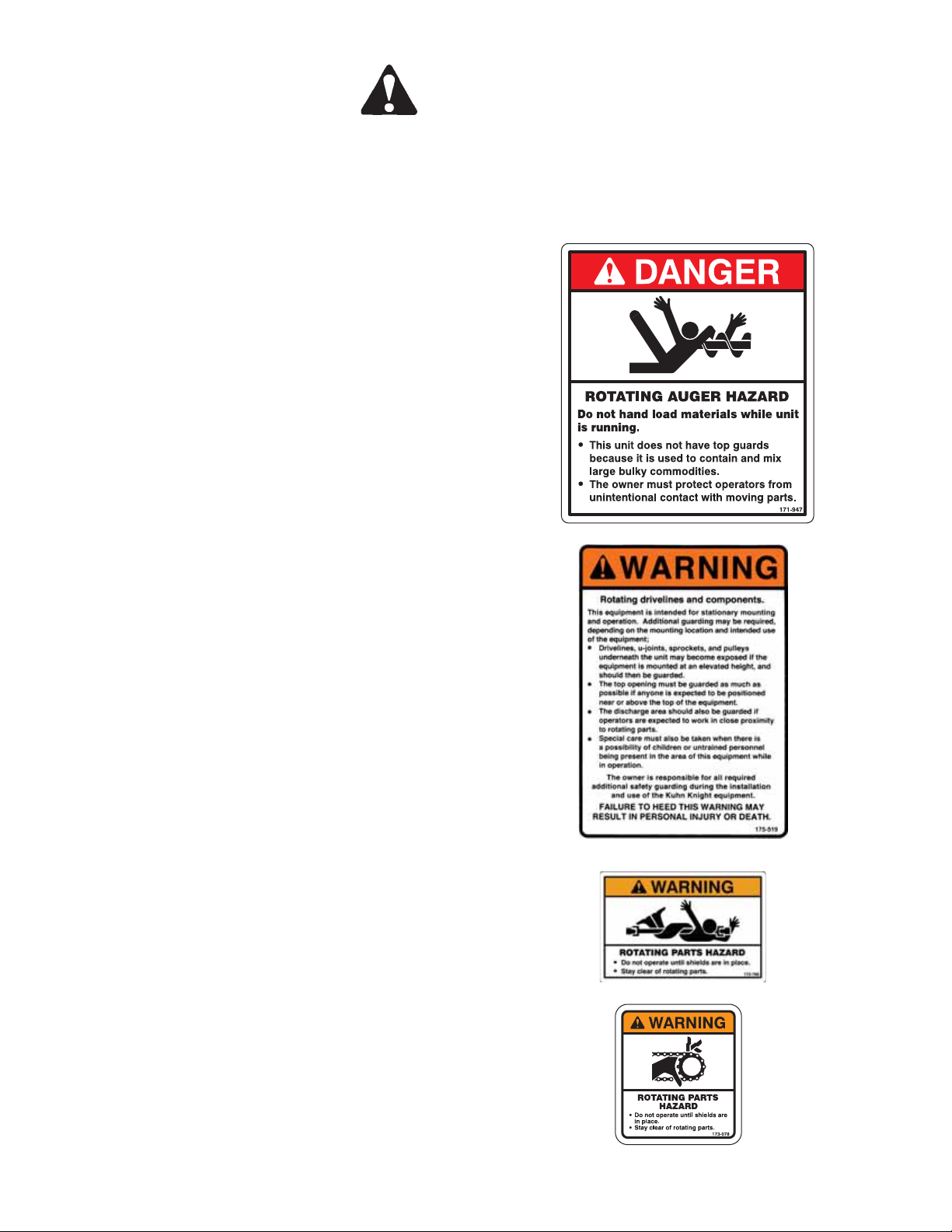
Figure G
DANGER, ROTATING AUGER HAZARD
Part Number 70171947
4 Required ALL MODELS
Figure H
WARNING, Rotating drivelines and components
Part Number 70175519
1 Required ALL MODELS
Figure I
WARNING, ROTATING PARTS HAZARD
Part Number 70172786
1 Required: 3136 & 3142 MODELS
1 Required: 3150, 3160, 3170 & 3195 MODELS
Figure J
WARNING, ROTATING PARTS HAZARD
Part Number 70173078
1 Required: 3136 & 3142 MODELS
1 Required: 3150, 3160, 3170 & 3195 MODELS
Back to Table of Contents
1501 West 7th Ave., Brodhead, WI 53520
701 Cherry Ave., Greeley, CO 80632
Kuhn Knight, Inc.
9
3100ST 006046 010507
SAFETY
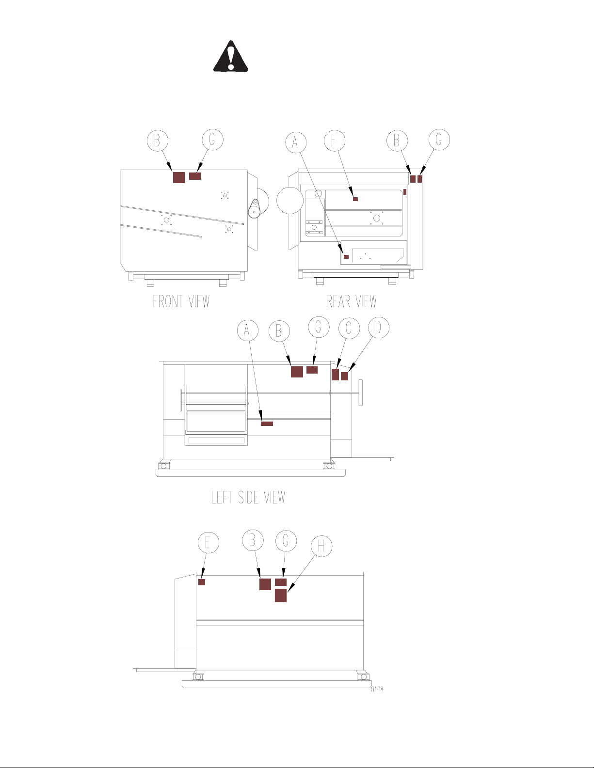
SAFETY DECAL PLACEMENT
MODEL 3115 S/N A0028 AND BEFORE
Shields removed for illustrative purposes
10
© Copyright 2004 Kuhn Knight, Inc.
Back to Table of Contents
SAFETY
SAFETY DECAL PLACEMENT
MODEL 3115 S/N A0029 AND AFTER
3100ST 006046 010507
Shields removed for illustrative purposes
Back to Table of Contents
1501 West 7th Ave., Brodhead, WI 53520
701 Cherry Ave., Greeley, CO 80632
Kuhn Knight, Inc.
11

3100ST 006046 010507
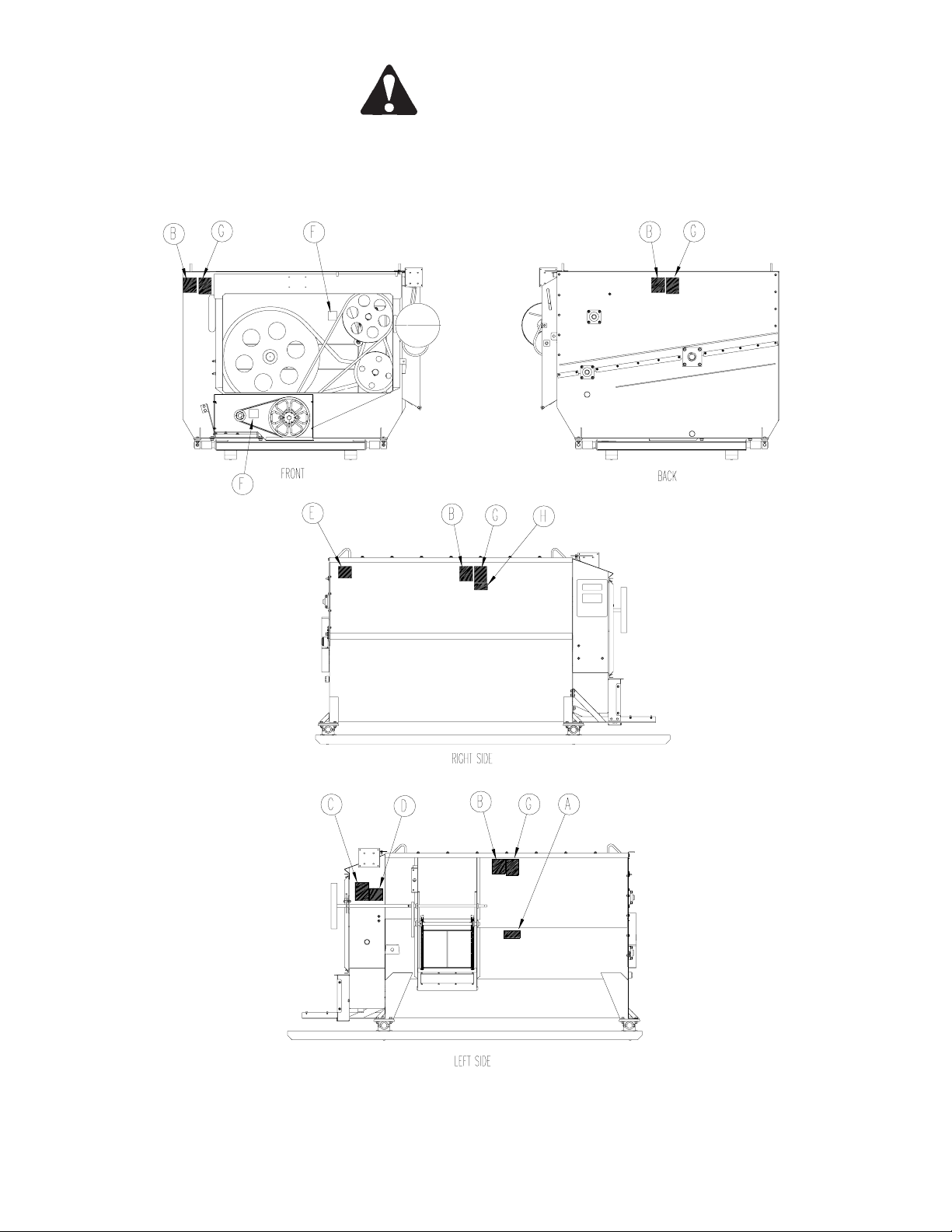
SAFETY DECAL PLACEMENT
MODEL 3120
SAFETY
Shields removed for illustrative purposes
12
© Copyright 2004 Kuhn Knight, Inc.
Back to Table of Contents

SAFETY DECAL PLACEMENT
MODELS 3125 AND 3130
3100ST 006046 010507
SAFETY
Shields removed for illustrative purposes
Back to Table of Contents
1501 West 7th Ave., Brodhead, WI 53520
Kuhn Knight, Inc.
701 Cherry Ave., Greeley, CO 80632
13

3100ST 006046 010507
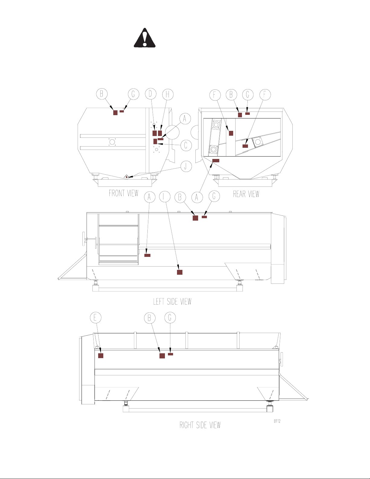
SAFETY DECAL PLACEMENT
MODELS 3136 & 3142
SAFETY
Shields removed for illustrative purposes
14
© Copyright 2004 Kuhn Knight, Inc.
Back to Table of Contents
SAFETY
SAFETY DECAL PLACEMENT
MODELS 3150, 3160, 3170 AND 3195
3100ST 006046 010507
Shields removed for illustrative purposes
Back to Table of Contents
1501 West 7th Ave., Brodhead, WI 53520
Kuhn Knight, Inc.
701 Cherry Ave., Greeley, CO 80632
15

3100ST 006046 010507
MIXER SETUP
READ AND FOLLOW THESE INSTRUCTIONS WHEN SETTING UP THE MIXER.
To avoid personal injury: The hopper floor may be slippery and the augers or reel can spin
unexpectedly when stepped on. Use caution when stepping or standing inside the unit; put a
protective cover over the auger knives.
INSTALLATION TIPS
1. Be sure there is adequate clearance around the mixer for maintenance, repair and loading the mixer.
2. If the electronic weighing system is used, be sure that the weigh bars are kept clean and dry. Also be sure
items such as loading conveyors are not attached to or leaning on the mixer. Refer to scale manual for more
specific information.
3. Mixer should be mounted on a structure of adequate strength to support a fully loaded mixer. Machine must be
level and stable at the desired height. Weigh bar mounts should be fastened to this structure.
4. Manual door opener for the 3115 & 3120 can be mounted at either the front or the rear of the mixer. The
following instructions will help to modify the door opener for operation from the opposite end:
A. Remove latch and mounting bolt and install to opposite end of mixer in corresponding hole.
B. Remove door wheel assembly.
C. With door in fully closed position, cut door wheel shaft to proper length, drill mount hole, slide
into position and replace bolt.
5. The 3125, 3130, 3136, 3142, 3150, 3160 and 3170 manual door opener is in a fixed position on the drive end of
the mixer.
6. An optional remote electric door actuator is also available for the 3115 and 3120 models. An electric/hydraulic
power pack is available for the 3125 through 3170 models. The power pack is standard on the 3195.
NOTE: When wiring the electric/hydraulic power pack, make sure to wire it to a switched source and ensure it
only runs when the door is activated.
Electric Motor Recommendations
Following is a listing of suggested motor and frame sizes. Ratings are based on “normal dairy feed rations”. Contact the factory if intending to mix heavier loads such as feedmill use, heavy/sticky beef rations or industrial use. A
smaller motor may be adequate for easy-mixing materials and a larger motor may be required for difficult
materials. Wiring and overload protection should be sized according to the motor size installed. The motor mount
will fit the recommended motor size. Other motor sizes may require additional holes to be drilled in the mount or a
different mount assembly. Dual motor mount, frame and shield are standard on 3125, 3130, 3136 & 3142 models.
All models are designed to be used with a motor operating at 1725-1750 RPM.
MODEL *HORSEPOWER
3115 7.5 - 10 213T - 215T 1-3/8” 1-1/8”
3120 10 215T - 254T 1-3/8” 1-5/8”
3125 10 254T - 256T 1-5/8” 1-3/8”
3130 10 - 15 254T - 256T 1-5/8” 1-3/8”
3136 15 - 20 256T - 284T 1-5/8” 1-7/8”
3142 15 - 25 284T - 286T 1-7/8” 2-1/8”
3150 50 326T 2-1/8” 2-1/8”
3160 60 364T 2-3/8” 2-3/8”
3170 70 365T 2-3/8” 2-3/8”
3195 100 N/A 2-7/8” - -
A smaller motor may be adequate for easy-mixing materials and a larger motor may be required for difficult materials
MOTOR
FRAME SIZE
STANDARD
MOTOR BUSHING
OPTIONAL
MOTOR BUSHING
16
© Copyright 2004 Kuhn Knight, Inc.
Back to Table of Contents

3100ST 006046 010507
MIXER SETUP
READ AND FOLLOW THESE INSTRUCTIONS WHEN SETTING UP THE MIXER.
To avoid personal injury: The hopper floor may be slippery and the augers or reel can spin
unexpectedly when stepped on. Use caution when stepping or standing inside the unit; put a
protective cover over the auger knives.
SAFETY SHIELDS
Be sure all shields are in place and functioning properly. Replace all damaged or missing shields immediately;
see Parts Manual for replacement shield part numbers.
BE AWARE that your installation may require additional safety shields and/or warnings. Because each installation
is different, Kuhn Knight Inc. cannot design standard shields for all conceivable situations without limiting the use of
the mixer. The top of the mixer and the door opening are the two areas that should be given particular attention in
regard to safety. The top of the mixer has a grid type safety shield to help prevent a person from falling into the
mixer. However, because there are many different feeds and ways of loading them, the top openings must be large
enough to avoid obstructing the loading operation. Likewise, the door opening area must be unobstructed to allow
the discharge of feed.
Kuhn Knight Inc. warns operators using decals on the mixer and specific instructions in this manual to stay clear of
these areas during operation. If safety decals are blocked from view due to the installation, then additional decals
should be ordered and placed so they are readable. If your particular installation is such that a person may inadvertently put an arm or leg in these areas during operation, then additional safety shielding must be installed to prevent
such an occurrence. Drives, u-joints, sprockets and pulleys underneath the unit may become exposed if the
equipment is mounted at an elevated height. Additional shielding of these areas may be necessary depending on
exact installation.
AUGER KNIVES
The upper auger knives are installed to help handle long materials such as long stem hay. If you do not intend to
handle this type of material, the knives can be removed. Commercial Reel models ordered with the Grain Series
package do not include knives unless a Hay Maxx System was installed.
REEL CROSS TUBES
The cross tubes have two settings which can be utilized depending on
the material being mixed. The tubes are factory set in the outer position.
In general, the inner setting is used for a high hay ration. To change to
the inner position, compress and secure the tube into the spring, and
relocate the capture bolt to the inner holes. The square wiper tubes
should not be moved. Repeat for all non-wiper tubes.
Back to Table of Contents
Kuhn Knight, Inc.
1501 West 7th Ave., Brodhead, WI 53520
701 Cherry Ave., Greeley, CO 80632
17

3100ST 006046 010507
MIXER SETUP
READ AND FOLLOW THESE INSTRUCTIONS WHEN SETTING UP THE MIXER.
To avoid personal injury: The hopper floor may be slippery and the augers or reel can spin
unexpectedly when stepped on. Use caution when stepping or standing inside the unit; put a
protective cover over the auger knives.
DRIVELINE SHEAR BOLTS
3136, 3142, 3150, 3160, 3170 & 3195 ONLY
The driveline has a shear bolt assembly for overload protection. This shear bolt type overload protection needs very
little maintenance. If the motor free spins during operation, the shear bolt has broken. Replace the sheared bolt with
a new one of the same diameter, length and grade. Any bolt of different specifications than listed below will prevent
the shear bolt assembly from operating properly and can cause damage to the mixer.
MODEL SHEAR BOLT SIZE
3136 1/4” X 2” GRADE 5
3142 1/4” X 2” GRADE 5
3150 1/4” X 2” GRADE 5
3160 1/4” X 2” GRADE 5
3170 5/16” X 2” GRADE 5
3195 5/16” X 2” GRADE 5
MIXER TEST RUN
1. Check for proper assembly, adjustment, and lubrication.Check to see that there is adequate oil in the oil
bath. Check to be sure all bolts and set screws are tight and the drive belts are at the proper tension. Review
OPERATING SAFETY PRECAUTIONS in the SAFETY section and the LUBRICATION section before
operating the mixer.
2. Be sure all shields are properly in place.
3. Check for and remove any foreign objects in the mixer hopper and discharge opening.
4. Check to see that drain plugs are installed and that the discharge door is closed.
5. Be sure no one is inside the mixer.
6. Test run the mixer.
a. Make sure mixer is empty, then start the mixer.
b. Run for at least five minutes.
c. Raise and lower the door several times.
d. Turn off mixer and lock out power.
e. Check the mixer drive components to be sure they are not abnormally hot. Refer to
Inspection and Adjustment section for proper alignment and tension settings.
If any of these items are not running as indicated, immediately repair or contact your service representative. Always
refer to OPERATING SAFETY PRECAUTIONS in the SAFETY section before operating or servicing the mixer.
18
© Copyright 2004 Kuhn Knight, Inc.
Back to Table of Contents

3100ST 006046 010507
MIXER OPERATION
Always refer to OPERATING SAFETY PRECAUTIONS and SAFETY DECALS in SAFETY section of this
manual before operating this mixer.
GENERAL
The Reel Auggie and Commercial Reel Mixer were designed for blending dairy and beef rations. Most
commonly used ingredients, including limited amounts of dry stem hay, can be mixed quickly and uniformly in this
mixer. If you have questions regarding your feed ration or have other applications, please contact Kuhn Knight Inc.
The Reel Auggie and Commercial Reel mixer’s mixing performance can vary greatly according to the differences in
materials, loading sequence, mixing speed, and unloading methods. The following guidelines should be understood
before operating the Mixer.
The Hay Maxx System is designed to start processing hay before it enters the mixing chamber. This is an efficient
way to add long stem hay to the ration. The hay pan holds the hay in position, while the auger begins to process
the hay with the aid of hard edge knives and shear angles. The hay pan, backstop, aggressive auger knives, and
shear angles, work in combination to tear hay apart faster for more even mixing.
When you see this Hay Maxx System logo
operation instructions.
The Roughage Maxx System is designed to complete hay processing once it reaches the mixer’s lower auger.
When you see this Roughage Maxx System logo , there are specific and special Roughage Maxx
System operating instructions.
, there are special and specific Hay Maxx System
SAFETY
When the mixer is in operation it has many moving parts which could cause severe injury or death to
persons coming in contact with these parts. To help avoid serious accidents, please read and understand
the OPERATING SAFETY PRECAUTIONS in the SAFETY section, located in the front of this manual.
Back to Table of Contents
Kuhn Knight, Inc.
1501 West 7th Ave., Brodhead, WI 53520
701 Cherry Ave., Greeley, CO 80632
19

3100ST 006046 010507
MIXER OPERATION
Always refer to OPERATING SAFETY PRECAUTIONS and SAFETY DECALS in SAFETY section of this
manual before operating this mixer.
LIMITATIONS
Do not load hay without other dry commodities in the mixer first to act as a carrier or “lubricant”.
Do not overload hay content. Kuhn Knight Inc. recommends a maximum of 15% to 20% of unprocessed hay by
weight in the load. Exceeding this percentage can decrease mixing performance or could potentially damage mixer
and cause premature wear on driveline components.
WARNINGS
Do not use tough hay (20% to 60% moisture) Always use cured, dry hay. Wet hay, foreign objects or overloading
may cause binding and damage to the mixer and hay pan.
Kuhn Knight Inc. will not be responsible for damage caused by overloading, wet hay or foreign objects.
Do not force hay into auger with loader or any other device. The area over the auger does not have bucket guards,
avoid bucket contact with the auger to prevent potential damage to knives and auger.
Do not overload Hay Maxx System with too much hay. This can cause bridging over the auger. Never
attempt to release jammed materials or clean out materials from the Hay Maxx System area without stopping
tractor engine and removing driveline.
Hay Maxx System and or the mixer.
Do not lower Hay Maxx System pan to force hay into the top auger. This will cause damage to the
MIXING TIME
The Mixer can mix an average load in 3 to 4 minutes. Due to this short mixing time, there is normally no reason to
run the mixer during loading except to level the materials or to break up hay.
mixer before loading the hay. Adjust the position of the Hay Maxx System pan to allow more processing (see HAY
MAXX SYSTEM ADJUSTMENTS in the INSPECTION & ADJUSTMENTS section.)
With Hay Maxx System option: If the hay goes through too fast, try loading more commodities in the
20
© Copyright 2004 Kuhn Knight, Inc.
Back to Table of Contents

3100ST 006046 010507
MIXER OPERATION
Always refer to OPERATING SAFETY PRECAUTIONS and SAFETY DECALS in SAFETY section of this
manual before operating this mixer.
MATERIAL THAT CAN BE LOADED DIRECTLY INTO THE MIXER
Many different kinds of materials can be mixed with the Reel Auggie or Commercial Reel Mixer, but each type has
its own unique characteristics.
FORAGES: Chopped hay, corn silage, and finely chopped crop residue can be mixed in the mixer. Wet and heavy
forages added in large volumes may require more power to mix.
GRAINS: Ground, rolled, flaked, and whole cereal grains, minerals, and concentrates, are all very easily mixed,
and can improve the mixing performance of the other materials.
LIQUIDS: Supplements and liquid fat can be blended in the mixer. Some operators prefer adding liquids into the
empty mixer, and others add liquids on top of grains or roughage. Sticky liquids such as molasses tend to increase
the power requirements.
MATERIALS REQUIRING PREPARATION
The following feed materials require some preparation or processing to be mixed in the Reel Auggie or Commercial
Reel Mixer:
- SMALL SQUARE BALES
- LARGE SQUARE BALES
- ROUND BALES
- ALL LONG AND UNCURED GRASSES
- STACKED FEEDS
The mixer can be used to mix rations with up to 15% to 20% dry alfalfa by using the Hay Maxx System. For
rations with a higher percentage of hay, mixing may be improved by pulling the non-wiper cross tubes to the inner
setting (see MIXER SETUP, REEL CROSS TUBES). This will allow the reel to more aggressively charge the lower
auger with hay.
Preparing Small Square Bales: Remove twine or wires while on the ground. Put bales into loader
bucket lengthwise so that they will fall onto the Hay Maxx System or, if the hay is dry cured alfalfa, load directly
into mixer equipped with Roughage Maxx option.
Preparing Large Square Bales (3’ x 3’ x 8’), (3’ x 4’ x 8’), (4’ x 4’ x 8’): Remove twine while on the
ground. Put slabs of the bale into the loader bucket (10” to 12” total thickness suggested maximum size). The hay
should lay flat against the Hay Maxx System pan to properly feed into the Hay Maxx System.
Preparing Round Bales: Remove the twine and break apart with loader, round bale slicer, round bale
unroller or other round bale processing equipment and load separated portions of hay into the Hay Maxx System.
Processing Long and Uncured Grasses: Pre-process in a tub grinder or a vertical mixer.
Processing Stacked Feeds: Break material apart with the loader or pre-process in a tub grinder.
HAY QUALITY
Always use cured, dry hay. Tough hay can cause wrapping or binding and may damage the mixer or adversely
affect the mixing performance. Some factors that contribute to tough hay are high moisture content, high grass
content, high density bales, outdoor storage, use of hay preservatives and excessive stem length.
Back to Table of Contents
1501 West 7th Ave., Brodhead, WI 53520
701 Cherry Ave., Greeley, CO 80632
Kuhn Knight, Inc.
21

3100ST 006046 010507
MIXER OPERATION
Always refer to OPERATING SAFETY PRECAUTIONS and SAFETY DECALS in SAFETY section of this
manual before operating this mixer.
LOADING AND MIXING
Prior to loading, check mixer for foreign objects and be sure door is fully closed.
1) LOAD COMMODITIES
Adding ingredients like corn, soybean meal, cottonseed, etc. will act as a carrier or “lubricant” if hay is
included in the ration.
If there are few commodities in the ration, substituting corn silage or haylage is preferred.
Fill mixer between 1/3 to 1/2 full by volume in commodities and forage before adding the hay to the ration.
This will allow enough room for hay to expand and bring feed level up so the top auger can assist in
processing.
2) LOAD HAY
A) LOAD PROCESSED HAY
With the mixer running, proceed loading the small square bale pieces or tub-ground hay into the mixer. Do
not exceed 15% to 20% of hay by weight.
The hay can be loaded after the previously added grains. Grains help to move the hay into the augers. It
often helps to have the mixer running while adding the hay and to load the hay on the auger side.
B) LOAD UNPROCESSED HAY
With the mixer running and the Hay Maxx System pan bolted in the “up” position, proceed using the loader
to begin placing the hay on the Hay Maxx System pan. Load the slabs toward the front end of the Hay
Maxx System pan, so the hay is not resting against the rear backstop.
For best results, do not overload the Hay Maxx System pan and allow time to process the hay in the
Hay Maxx System before adding more. Repeat until proper percentage of hay for ration is met.
(not to exceed 15% to 20% hay by weight)
Note: Hay processing time with the Roughage Maxx option may be reduced due to the aggressive
knives. Hay particle length may be reduced much faster when using the Roughage Maxx option,
processing time should be adjusted accordingly to avoid over processing.
3) Finish Loading Commodities
Finish loading any other ingredients to complete the ration in order of least binding ingredient to most binding.
Example: dry commodities first, corn silage second, haylage last.
4) Finish Loading Wet Commodities
Any other wet feeds may be added at this time.
5) Add Water
If ration includes water, add it last. Adding water at the beginning will cause the hay to bind.
NOTE: Do not overload mixer! Overloading causes excessive horsepower requirements, increased strain on
driveline and poor mixer performance.
22
© Copyright 2004 Kuhn Knight, Inc.
Back to Table of Contents

MIXER OPERATION
Always refer to OPERATING SAFETY PRECAUTIONS and SAFETY DECALS in SAFETY section of this
manual before operating this mixer.
FILL LEVEL
Do not overload mixer! Overloading causes excessive horsepower
requirements, increased strain on mixer driveline and poor mixer
performance.
The design of the Reel Auggie and Commercial Reel Mixer
requires that there be adequate space to allow the feed to move in
and around the reel chamber. If the reel is completely covered, it
cannot efficiently mix the materials. The reel cross tubes should
always be visible at the top of their rotation to allow this mixing
space.
Do not exceed full line as shown in diagram.
UNLOADING
3100ST 006046 010507
After the ration has been thoroughly mixed, open the mixer door to begin unloading. The discharge door opening
determines the flow of feed from the mixer. The door must be opened far enough to prevent separation of materials.
Optional door flow control plates are available to help prevent separation.
To stop the flow of feed, close the door, then shut off the mixer.
Back to Table of Contents
Kuhn Knight, Inc.
1501 West 7th Ave., Brodhead, WI 53520
701 Cherry Ave., Greeley, CO 80632
23

3100ST 006046 010507
OPTIONS
All Options are available as original equipment or field installation.
DOOR FLOW CONTROL PLATES
Longer feedstuffs will unload smoother and more evenly through a “tall and narrow” opening versus a “short and
wide” opening. Flow control plates have been developed, which allow the operator to use a smaller or existing
conveyor to carry feed from the mixer while keeping the discharge flow of feed (especially long stem hay/haylage
mix) even and smooth. See “Door Parts” section of the corresponding Parts Manual for flow control plate part
numbers.
NOTE: Feed separation may occur if the door is not opened far enough.
ELECTRIC DOOR CONTROL
This option allows the discharge door to be operated from a location away from the mixer, or when an installation
location requires remote door operation.
ELECTRONIC SCALES
Allows accurate ration weight while loading, also scale indicator can be located away from mixer if a more convenient location is preferred. Refer to the manufacturer’s operator’s manual for your specific scale option operation
and maintenance.
HAY MAXX SYSTEM
A bolt-in option designed for the user who wants to more effectively add long stem hay to the ration.
The Hay Maxx System handles small and large square bales, broken-up round bales, frozen bunker silage and
other bulky materials, without over-processing.
ROUGHAGE MAXX SYSTEM
A system of additional lower auger scallop knives that enhance hay processing performance of the reel mixer, with
or without the optional Hay Maxx System. It is designed to allow the lower auger to do more cutting of long stem
hay and roughages, even after hay has been introduced to the ration through the Hay Maxx System.
24
© Copyright 2004 Kuhn Knight, Inc.
Back to Table of Contents

3100ST 006046 010507
INSPECTIONS AND ADJUSTMENTS
Always stop mixer and lock out the power before servicing, repairing or cleaning the machine.
If work must be done inside the mixer, put a protective cover over the auger knives to avoid injury. The hopper
floor and fighting may be slippery. Use caution when stepping on or standing inside the machine.
Use safe shop procedures and exercise caution when working on the mixer!
INSPECT AND ADJUST...
...Roller Chain Tighteners so they will apply sufficient spring tension to keep roller chains running smoothly. As a
general rule the thickness of a nickel should fit between the spring coils. The chain will form grooves in the tightener
blocks. These grooves help to keep the chains in proper alignment and the blocks need not be turned unless the
roller portion of the chain has worn into the block.
...Roller Chains for wear, proper alignment and tension. Adjust or replace if necessary. Roller chain connector
links, which pass over polyethylene tightener blocks, must be installed with legs of the cotter pins trailing to the
direction of rotation.
...Safety Decals for legibility. If any safety decals are removed, obstructed, or otherwise not understandable, they
should be replaced immediately. Keep all decals clean - see SAFETY DECALS in the SAFETY section for more
information.
...Safety Shields to be sure all shields are in place and functioning properly. Replace all damaged or missing
shields immediately - see Parts Manual for shield part numbers.
...Bolts and Set Screws after a few hours of use and each month thereafter. Tighten if necessary.
...Reel Cross Tubes so that they slide in freely when compressed against the spring; the spring pockets may
need occasional cleaning. This sliding action helps prevent jamming and avoids overloading of the driveline.
...Reel Wiper Tubes for the condition of the plastic wiper strips, which help material clean out of the reel hopper. If
the strips become bent backward, they can be unbolted and be reinstalled backward or replaced to improve clean
out.
...Knives for damage or wear.
Upper Auger Knives can be turned over for use of a new cutting edge and should be periodically sharpened
or replaced if they no longer sufficiently break up material.
Round Lower Auger Knives can be rotated several times before sharpening or replacement is required.
Bolt-on Scallop Knives are to be replaced when they are worn.
Small Knives on the flighting perimeter are to be welded in when replacement is necessary.
...Motor Fan Guard. The fan guard must be kept clean to allow sufficient air flow for proper motor cooling.
...Drive Belts for wear and hardness. Old belts will be brittle or hard and must be replaced. Pulley misalignment
often causes belt wear and this alignment should be checked when replacing any worn belt. Inspect pulleys for
wear or damage both on the grooves and on the shaft diameter. Clean and dry belts thoroughly before reassembly.
Tighten belts to a tension that will allow the belt to deflect 1/2” when a 10lb. force is applied in the middle of the belt
span. Belts should be kept clean, dry and oil free.
IMPORTANT: WHEN WELDING ON THIS UNIT: DO NOT allow the current to flow through the bearings, roller
chains, or scale weigh bars. Ground directly to the item being welded. ALWAYS disconnect weigh bar cords from
scale indicator before welding.
Back to Table of Contents
1501 West 7th Ave., Brodhead, WI 53520
701 Cherry Ave., Greeley, CO 80632
Kuhn Knight, Inc.
25

3100ST 006046 010507
INSPECTION AND ADJUSTMENTS
IMPORTANT! Read before operating mixer.
It is the responsibility of the owner to make sure the mixer is set up properly.
The following recommendations should be helpful.
ELECTRONIC SCALES
Scale Indicator: Refer to the electronic scale operator’s manual for adjustment information. The operator’s manual
for the Electronic Scales should be kept with this manual. Additional copies of scale manuals may be obtained
through Kuhn Knight, Inc.
Load cells and weigh bars should be kept clean, dry and lubricated to ensure dependability.
3150 - 3195 AND
3136 BEFORE S/N B0001,
3142
Check arm assembly must be free to rotate slightly
by hand when mixer is on level ground with mounting
bolts tight.
BEFORE S/N B0001
3150 TO 3195 AND
3136 BEFORE S/N B0001,
3142
Vertical check bolts must not be tight and should be free to
rotate by hand. There should be 1/16” to 3/32” free play when
properly adjusted on level ground.
BEFORE S/N B0001
3136 BEFORE S/N B0001,
3142
BEFORE S/N B0001
PIN CHECK BEARING should be centered on the pin
when mixer is on level ground. Adjustment can be made
by loosening the mounting bolts, centering pin check
assembly on the pin and tightening the mounting bolts. If
bushing cannot be centered load cells may require
adjustment.
NORMAL SCALE ACTIVITY
Some warm up scale drift may occur after the scale is turned on but should zero balance within 10 to 15 minutes.
Scale may zero shift over night due to temperature changes.
26
© Copyright 2004 Kuhn Knight, Inc.
Back to Table of Contents

INSPECTION AND ADJUSTMENTS
IMPORTANT! Read before operating mixer.
It is the responsibility of the owner to make sure the mixer is set up properly.
The following recommendations should be helpful.
HAY MAXX SYSTEM ADJUSTMENTS
To avoid personal injury: The hopper floor may be slippery and the reel and augers can spin
unexpectedly when stepped on. Use caution when stepping or standing inside the unit, put a protective
cover over the auger knives, and be prepared to handle the unbalanced weight of the hay pan as it is
moved into its fixed position. Care should be taken to avoid pinch points and the knives on the upper auger
as the pan is moved into place.
The Hay Maxx pan must be bolted in the fully extended upright position.
3100ST 006046 010507
vary in quality, moisture and material; all affecting how the hay goes through the Hay Maxx System. Knife-to-pan
tolerance should never be adjusted to less than 1/2” or greater than 1”. The factory setting is 1/2” - 5/8”; field testing
shows this tolerance is best for most materials.
TO ADJUST HAY PAN POSITION: Loosen bolts (3 in front & 2 at rear) at the locations shown, make adjustment,
then securely retighten all five bolts.
Adjusting the knife-to-pan tolerance may be necessary for different types of feedstuffs. Hay may
Back to Table of Contents
Kuhn Knight, Inc.
1501 West 7th Ave., Brodhead, WI 53520
701 Cherry Ave., Greeley, CO 80632
27

3100ST 006046 010507
LUBRICATION
ALWAYS STOP MIXER AND DISCONNECT POWER BEFORE SERVICING, REPAIRING OR
CLEANING. USE SAFE SHOP PROCEDURES AND EXERCISE CAUTION WHEN WORKING ON
THIS MIXER!
It is extremely important that the following lubrication guide be followed:
For lubricating bearings, use a good quality multipurpose grease. Replace all damaged or missing grease
zerks immediately. Always clean zerks before using grease gun. Pump the grease in slowly until a slight bead
forms around the bearing seals. Once a month check lines and connections on grease banks for leaks.
Before operating a new mixer, the roller chains should be liberally lubricated and then the unit operated
under a no-load condition.This break-in period will allow the roller chains to be thoroughly lubricated and thus
minimize heat-up during operation.
The large drive enclosure is designed to be used as an oil bath. Fill front enclosure until the oil level reaches
the plug labeled “oil level ”on the enclosure.
LUBRICATION LOCATIONS
3115
* * * shields removed for illustrative purposes
28
© Copyright 2004 Kuhn Knight, Inc.
Back to Table of Contents

LUBRICATION LOCATIONS
3120
3100ST 006046 010507
LUBRICATION
* * * shields removed for illustrative purposes
Back to Table of Contents
1501 West 7th Ave., Brodhead, WI 53520
701 Cherry Ave., Greeley, CO 80632
Kuhn Knight, Inc.
29

3100ST 006046 010507
LUBRICATION LOCATIONS
3125 AND 3130
LUBRICATION
* * * shields removed for illustrative purposes
30
© Copyright 2004 Kuhn Knight, Inc.
Back to Table of Contents

LUBRICATION
LUBRICATION LOCATIONS
3136, 3142, 3150, 3160, 3170 AND 3195
3100ST 006046 010507
* * * shields removed for illustrative purposes
Back to Table of Contents
1501 West 7th Ave., Brodhead, WI 53520
701 Cherry Ave., Greeley, CO 80632
Kuhn Knight, Inc.
31

3100ST 006046 010507
TROUBLE SHOOTING
This section is a condensed chart to help you if unsatisfactory operation occurs.
To use this chart : 1) Identify the “PROBLEM” (in bold) that best applies to you situation.
2) Find the “CAUSE” that seems most likely.
3) Perform the recommended “SOLUTION”.
If you are unable to identify and correct the problem, consult your authorized dealer.
PROBLEM:
- POOR MIXING PERFORMANCE, HAY IS WRAPPING ON AUGERS
- CROSS PIPES ON THE REEL ASSEMBLY ARE BENT
- BELTS SLIPPING
- SHEAR BOLT FAILS
- EXCESSIVE POWER REQUIREMENTS WHEN RUNNING MIXER
CAUSE SOLUTION
MIXER IS OVERLOADED Reduce load size, feed must be able to tumble from the reel cross
HAY IS LOADED ON THE REEL SIDE OF THE MIXER Load hay on the auger side of the mixer. This keeps hay from
BIG CHUNKS OF HAY Break up bales before loading.
CROSS PIPES SET IN THE OUTER POSITION Move reel cross pipes to the inner setting by compressing the
HAY IS NOT FULLY CURED Freshly baled hay tends to be green and does not tear apart easily.
AUGER KNIVES ARE NOT SHARP Sharpen or replace knives when they become dull.
HAY IS TOO LONG Round baled and stacked hay cannot be used in the mixer unless it
HAY PERCENTAGE IS TOO HIGH Mix a lower percentage of hay or change loading sequence. When
pipes. If reel is over full, mixing action will be greatly reduced. Feed
must not pile up between the reel and the side of the mixer. This
causes a buildup of pressure, increases the power requirements of
the mixer, and can cause pipes to bend.
being caught between the reel pipes and side of mixer during
initial loading.
springs and adding bolts and lock nuts in the reel arms. Do not move
wiper arms in. See REEL CROSS TUBES in the MIXER SETUP
section.
Allow hay to dry or cure longer before using in the mixer.
has been processed first, Some grassy types of hay must also be
processed before it can be used. See MATERIALS REQUIRING
PREPARATION in the MIXER OPERATION section.
mixing the hay, run the mixer at full rated speed. See MIXER
SETUP section.
FOREIGN OBJECT IN MIXER Inspect mixer and remove object.
IMPROPER LOADING SEQUENCE See LOADING AND MIXING in the MIXER OPERATION section for
FORAGE IS PILED ABOVE REEL AND WEDGED Mixer is overloaded or operator must load forage after the mixer is
AGAINST MIXER WALL started.
32
© Copyright 2004 Kuhn Knight, Inc.
recommended loading sequence.
Back to Table of Contents

TROUBLE SHOOTING
PROBLEM: MOTOR RUNS, BUT REEL AND AUGERS DO NOT TURN
CAUSE SOLUTION
3100ST 006046 010507
SHEAR BOLT ON PTO DRIVELINE HAS SHEARED
BELTS ARE SLIPPING
BROKEN CHAIN
Replace with the same grade and size shear bolt. Do not use any
bolt other than the grade specified in the MIXER SETUP,
DRIVELINE SHEAR BOLTS section. If problem persists, call your
local dealer.
Adjust or replace belts ad outlined in the INSPECTION AND
ADJUSTS section. If problem persists, call your authorized Kuhn
Knight service dealer.
Make sure that mixer is not overloaded. Replace broken chain. A
spliced chain will not be as strong as a new chain and may break
in another place. Be sure to inspect bearings, bearing mounts,
and shafts for any damage caused by excessive pressure.
PROBLEM: SEAL LEAKING ON UPPER AUGER
CAUSE SOLUTION
BOLTS MAY HAVE WORKED LOOSE ON SEAL RETAINER Tighten or replace bolts
SEAL IS DAMAGED Replace Seal
PROBLEM: SEAL LEAKING ON INPUT SHAFT
CAUSE SOLUTION
OIL BATH IS OVERFILLED The oil level in the sealed drive compartment should be maintained
at the “oil level” plug on the drive compartment housing. This
allows the oil to be thrown onto all the other chains inside the
drive compartment.
SEAL IS DAMAGED Replace Seal
PROBLEM: EXCESSIVE CHAIN NOISE
CAUSE SOLUTION
MISALIGNED SPROCKETS Check sprockets for worn edges of teeth. Use a straight edge to
WORN SPROCKET AND OR CHAIN Inspect sprockets and chains. Replace if excessively worn.
verify the alignment of the sprockets.
PROBLEM: FEED IS SEPARATING AS IT DISCHARGES FROM THE MIXER DOOR
CAUSE SOLUTION
DOOR IS OPEN LESS THAN HALF WAY Hay mixed in the load will separate from the grain if the discharge
Back to Table of Contents
Kuhn Knight, Inc.
1501 West 7th Ave., Brodhead, WI 53520
701 Cherry Ave., Greeley, CO 80632
door is not open at least half way. Additional flow control plates
may be required.
33

3100ST 006046 010507
TROUBLE SHOOTING
PROBLEM: OIL LEAKING AROUND THE EDGES OF THE OIL BATH
CAUSE SOLUTION
INSPECT SHIELD FOR LOOSENESS
DAMAGED OR LOOSE GASKET MATERIAL AROUND
ENCLOSURE SHIELD
Check for foreign material between the foam gasket and shield.
Carefully tighten wing nuts or adjust locking fasteners that hold
shield in place; hand tighten only.
Remove shield and check gasket material for proper adhesion to
the mating panel of the mixer. If gasket adhesive has come
loose fro the front panel, replace the gasket.
PROBLEM: HYDRAULIC DOOR SYSTEM OPERATES ERRATICALLY
CAUSE SOLUTION
COMPONENTS STICKING OR BINDING Check for hydraulic oil for contamination, dirt, or gummy deposits;
INADEQUATE FLOW OR PRESSURE FROM HYDRAULIC SYSTEM. Check fluid and fill to proper level.
OIL IS LEAKING PAST SEALS IN CYLINDERS OR VALVES Install seal kits to repair worn seals. See Parts Manual for part
find and repair the source of contamination. Check for worn or
bent parts and replace. Check oil level in hydraulic system.
numbers.
PROBLEM: SCALE HANGS UP, LOAD CELL ONLY
CAUSE SOLUTION
LOAD CELL NOT VERTICAL With the mixer empty, adjust the load cell by loosening top load
cell mount, move the load cell to a vertical position and retighten
the load cell mount’s fasteners.
PIN CHECK OUT OF ADJUSTMENT Remove pin check assembly, test scale, if scale operates
CHECK ARM NOT LUBRICATED Lubricate check arm until it easily rotates on sockets.
properly clean or repair pin check assembly. See INSPECTIONS
AND ADJUSTMENTS, ELECTRONIC SCALES section.
See INSPECTIONS AND ADJUSTMENTS, ELECTRONIC
SCALES section.
PROBLEM: SCALE WEIGHS VERY HEAVY OR VERY LIGHT, WEIGH BAR ONLY
CAUSE SOLUTION
IMPROPER CALIBRATION Use the scale’s operator’s manual and re-calibrate the scale.
DAMAGED CABLE ON ONE OR MORE Inspect cables and repair or replace as necessary.
LOAD CELLS OR WEIGH BARS
34
© Copyright 2004 Kuhn Knight, Inc.
Back to Table of Contents

SPECIFICATIONS 3115 TO 3142
MODEL - STATIONARY 3115 3120 3125 3130 3136 3142
DIMENSIONS (INCHES)
A - Overall Length - with motor mount 113 159 160 184 181 205
B - Overall Height - with rails and scales 64 64 69 69 83 83
C - Overall Width - with magnet tray 89 95 97 97 105 105
D - Height of Discharge - with rails and scales 17 18 19 19 28 28
E - Motor Mount to Center of Discharge Door 50 65 66 66 60 60
F - Overall Width Top Opening 71 78 81-1/2 81/1/2 87 87
G - Overall Length Top Opening 82 120 120 144 132 156
H - Height Reduction - less rails and scales 7 7 6-1/2 6-1/2 10 10
I - Length Reduction - less motor mount 12 36 36 NA
SPECIFICATIONS
Unit Weight 1 - pounds 2,850 4,809 6,489 7,021 8,480 8.762
Mixing Capacity - cubic foot/bushels 147/118 216/174 250/200 300/240 360/288 420/340
Reel Diameter 52” 52” 60” 60” 68” 68”
Reel Drive Shaft Diameter 3” 3-1/2” 3-1/2” 3-1/2” 4” 4”
Reel Arms 344455
Reel Hopper Thickness 3/16” 3/16” 5/16” 5/16” 5/16” 5/16”
Reel Speed RPM 4.37 4.89 4.60 4.60 4.0 4.0
Lower Auger
Flighting Diameter 16” 16” 18” 18” 20” 20”
Flighting Thickness - Sectional 3/8” 3/8” 3/8” 3/8” 1/2” 1/2”
Tube-Outside Diameter 4” 4” 5-9/16” 5-9/16” 5-9/16” 5-9/16”
Drive Shaft Diameter 2” 2-1/2” 2-1/2” 2-1/2” 3” 3”
Upper Auger
Flighting Diameter 14” 14” 18” 18” 20” 20”
Flighting Thickness - Sectional 3/8” - H 3/8” - H 3/8” - H 3/8” - H 1/4” - S 1/4” - S
Tube-Outside Diameter 4” 4” 5-9/16” 5-9/16” 5-9/16” 5-9/16”
Drive Shaft Diameter 2” 2” 2-1/2” 2-1/2” 3” 3”
Auger Hopper Thickness 1/4” 1/4” 5/16” 5/16” 5/16” 5/16”
Side Sheets Thickness 10 ga. 10 ga. 10 ga. 10 ga. 10 ga. 10 ga.
End Sheets Thickness 10 ga. 10 ga. 3/16” 3/16” 3/16” 3/16”
Door Opening Size 20” x 16” 36"x20" 36"x20" 36"x20" 36"x20" 36"x20"
Oil Bath Front Front Front Front Rear Rear
Roller Chain Drive
Electric Drive (HP)
1
Unit is equipped with most common options.
2
Horsepower requirements vary greatly with different
materials. Consult operators manual for proper motor sizing.
2
50-60-80 60H-80-100H 60H-80H-100H 60H-80H-100H 80-100-120 80-100-120
7-1/2-10 10 10 10-15 15-20 15-25
We reserve the right to change any equipment
specifications, design, or materials without notice. Contact
factory for nonagricultural use or heavier materials. US and
foreign patents filed.
Always read and understand the
Operators Manual and all Safety
Decals before using the
equipment.
SAFETY
FIRST
1501 West 7th Ave., Brodhead, WI 53520
701 Cherry Ave., Greeley, CO 80632

SPECIFICATIONS 3150 TO 3195
MODEL - STATIONARY 3150 3160 3170 3195
DIMENSIONS (INCHES)
A - Overall Length - with motor mount
B - Overall Height - with rails and scales 84 84 84 95
C - Overall Width - with magnet tray 114 114 114 125
D - Height of Discharge - with rails and scales 26 26 26 30
E - Motor Mount to Center of Discharge Door 70 70 70 NA
F - Overall Width Top Opening 93 93 93 108
G - Overall Length Top Opening 168 198 228 216
H - Height Reduction - less rails and scales 51/2 51/2 51/2 NA
I - Length Reduction - less motor mount 36 36 36 NA
SPECIFICATIONS
Unit Weight 2 - pounds 11,788 13,599 17,295 20,500
Mixing Capacity - cubic foot/bushels 500/415 600/490 700/562 950/763
Reel Diameter 70 70 70 84
Reel Drive Shaft Diameter 5" 5" 5" 8" tube
Reel Arms 5 5 5 5
Reel Hopper Thickness 3/8" 3/8" 3/8" 3/8"
Reel Speed RPM 5.7 5.7 5.7 5.2
Lower Auger
Flighting Diameter 24 24 24 28
Flighting Thickness 3 - Sectional 5/8" 5/8" 5/8" 5/8"
Tube-Outside Diameter 65/8" 65/8" 85/8" 85/8"
Drive Shaft Diameter 31/2" 31/2" 31/2" 5"
Upper Auger
Flighting Diameter 22 22 24 28
Flighting Thickness - Sectional 1/2" 1/2" 1/2" 1/2"
Tube-Outside Diameter 65/8" 65/8" 85/8" 85/8"
Drive Shaft Diameter 31/2" 31/2" 31/2" 4"
Auger Hopper Thickness 3/8" 3/8" 3/8" 3/8"
Side Sheets Thickness 3/16" 3/16" 3/16" 1/4"
End Sheets Thickness 1/4" 1/4" 1/4" 1/4"
Door Opening Size 42"x22" 42"x22" 42"x22" 48”x26"
Roller Chain Drive
Electric Drive (HP)
1
3195 motor mounts to the floor and dimension includes
motor, 18 in. driveline and gearbox.
2
Unit is equipped with most common options.
3
3/4 in. flighting at convergence is standard.
4
HP requirements may vary with different materials. Consult
operators manual for proper motor sizing.
4
1
224 254 284 307
80-100-120-140 80-100-120-140 80-100-120-140
80-120-140-Dbl 140
50 60 70 100
We reserve the right to change any equipment
specifications, design, or materials without notice. Contact
factory for nonagricultural use or heavier materials. US and
foreign patents filed.
Always read and understand the
Operators Manual and all Safety
Decals before using the
equipment.
SAFETY
FIRST
1501 West 7th Ave., Brodhead, WI 53520
701 Cherry Ave., Greeley, CO 80632
 Loading...