

Page 1

RA2584
Operator‘s manual
Original operator‘s manual
Edition 10.2012
Date of print 09.2014
Language EN-EU
Machine number VF65882401 –
Model VF6588
Document number VF16661959.EN-EU
Page 2

Machine identification
In order for your dealer to assist you as efficiently as possible, you will need to provide some information about
your machine. Please enter the details here.
Designation
Working width
Weight
Machine
number
Accessories
Address of
supplier
RA2584
7.60 m - 8.40 m
1950 kg
VF6588 _ _ _ _
Address of
manufacturer
Kverneland Group Kerteminde AS
Taarupstrandvej 25
DK-5300 Kerteminde
Denmark
Tel: +45 65 19 19 00
Copyright by Kverneland Group Gottmadingen N. V., Germany. Reproduction, transfer to other media, translation or the use of extracts or parts
of this manual without the explicit permission of Kverneland, is not permitted. All rights reserved. The contents of this operating manual are subject
to change without notice. The right to technical revision is reserved.
Page 3

Table of contents
Preface ....................................................... 4
Target group for this operating manual 4
Symbols used 5
Safety ......................................................... 6
For your safety 6
Who is allowed to
operate the machine? 10
General safety information 10
Coupling 14
Hydraulics 15
Road transport 16
Operation 18
Uncoupling 19
Care and maintenance 20
Further regulations 21
Getting to know the machine .................. 22
Range of application 22
Features 22
Component designations 23
Technical specifications 24
Pilotbox [+] 28
Delivery and assembly ............................. 31
Checking the scope of delivery 31
Checking the length of the PTO shaft 32
Checking the steering 34
Coupling the machine .............................. 35
Safety 35
General 35
Coupling the lower link 36
Swivelling in the parking stand 37
Coupling the PTO shaft 38
Wheel chocks 39
Connections 40
Preparing for use ...................................... 43
Safety 43
General 44
Rotor pitch 45
Lifting the tines 47
Working depth 48
Road transport .......................................... 50
Safety 50
General 51
Prior to road transport 52
Road transport 57
Table of contents
Operation ................................................... 66
Safety 66
General 67
Swathing 68
Swath deposit 69
Adjusting the swath width 73
Driving on headlands 73
Cleaning and care ..................................... 74
Safety 74
Cleaning 75
Care 75
Parking and storage .................................. 76
Setting down the machine in a
secure position 76
General 77
After the end of the season 77
Maintenance ............................................... 78
For your safety 78
General 80
Bolt connections 82
Lubrication points for grease 84
Lubricating the PTO shafts 85
Lubricate rotors 86
Filling quantities 87
Tyres 87
Hydraulics 88
Additional equipment ................................ 91
Additional equipment 91
Eliminating faults ...................................... 93
Faults 93
Circuit diagrams ........................................ 94
Hydraulic circuit diagram 94
Lighting circuit diagram 95
Decommissioning ..................................... 96
Environment 96
EC Conformity Declaration ....................... 97
Conforms to
EC Directive
2006/42/EC 97
Index ........................................................... 99
Preparations on the field ......................... 58
Safety 58
General 59
Folding the machine into the
work position 60
Basic settings 63
3
Page 4

Preface
Preface
Target group for this operating manual
Training
This operating manual is aimed at trained agriculturists and persons
who are otherwise qualified for agricultural activities and have
received instruction in working with this machine.
For your safety
You must familiarise yourself with the contents of this operating
manual before assembly or initial operation of the machine. In this
way, you will achieve optimum work results and operational safety.
The operating manual forms an integral part of the machine and must
always be kept to hand. This will ensure that you:
• avoid accidents.
• comply with warranty conditions.
• have a fully functional machine in good working order at all times.
Your dealer will provide instruction on operation and care of the
machine.
Information for the employer
All personnel are to be regularly, but at least once a year, instructed
on the use of the machine, in accordance with the regulations of the
national organisation for Health and Safety at Work. Untrained or unauthorised persons are not permitted to use the machine.
You are responsible for ensuring that the machine is operated and
maintained safely. Make sure that you and all other persons that
operate, maintain or work in close proximity with the machine are
familiar with the operating and maintenance regulations, as well as the
corresponding safety instructions in this operating manual.
4
Page 5

Preface
Symbols used
In this operating manual, the following symbols and terms have been
used:
• A bullet point accompanies each item in a list.
A triangle indicates operating functions which must be performed.
An arrow indicates a cross-reference to other sections of this
manual.
[+] A plus sign indicates additional equipment which is not included in
the standard version.
We have also used pictograms to help you find instructions more
quickly:
The “Information” pictogram points to tips and additional information.
The “Examples” pictogram indicates examples that assist understanding of the instructions.
Caution
The warning triangle indicates important safety information. Failure
to observe this safety information can result in:
• Serious faults in the correct operation of the implement.
• Damage to the machine.
• Personal injury or accidents.
The spanner indicates tips for assembly or adjustment work.
This arrow in the diagram shows the direction of travel.
The brush indicates the points that must be lubricated using the brush.
The grease gun indicates the points that must be lubricated using the
grease gun.
Switch on the tractor.
Secure the tractor against rolling away, shut off the engine and re-
move the ignition key.
5
Page 6

Safety
Safety
For your safety
This chapter contains general safety instructions. Each chapter of the
operating manual contains additional specific safety information which
is not described here. Observe the safety information:
• in the interest of your own safety.
• in the interest of the safety of others.
• to ensure the safety of the machine.
Numerous risks can result from handling agricultural machinery in the
wrong way. Therefore, always work with particular care and never
under time pressure.
The employer should:
Inform all persons who work with the machine about this safety
information at regular intervals and in accordance with statutory regulations.
6
Page 7
Safety
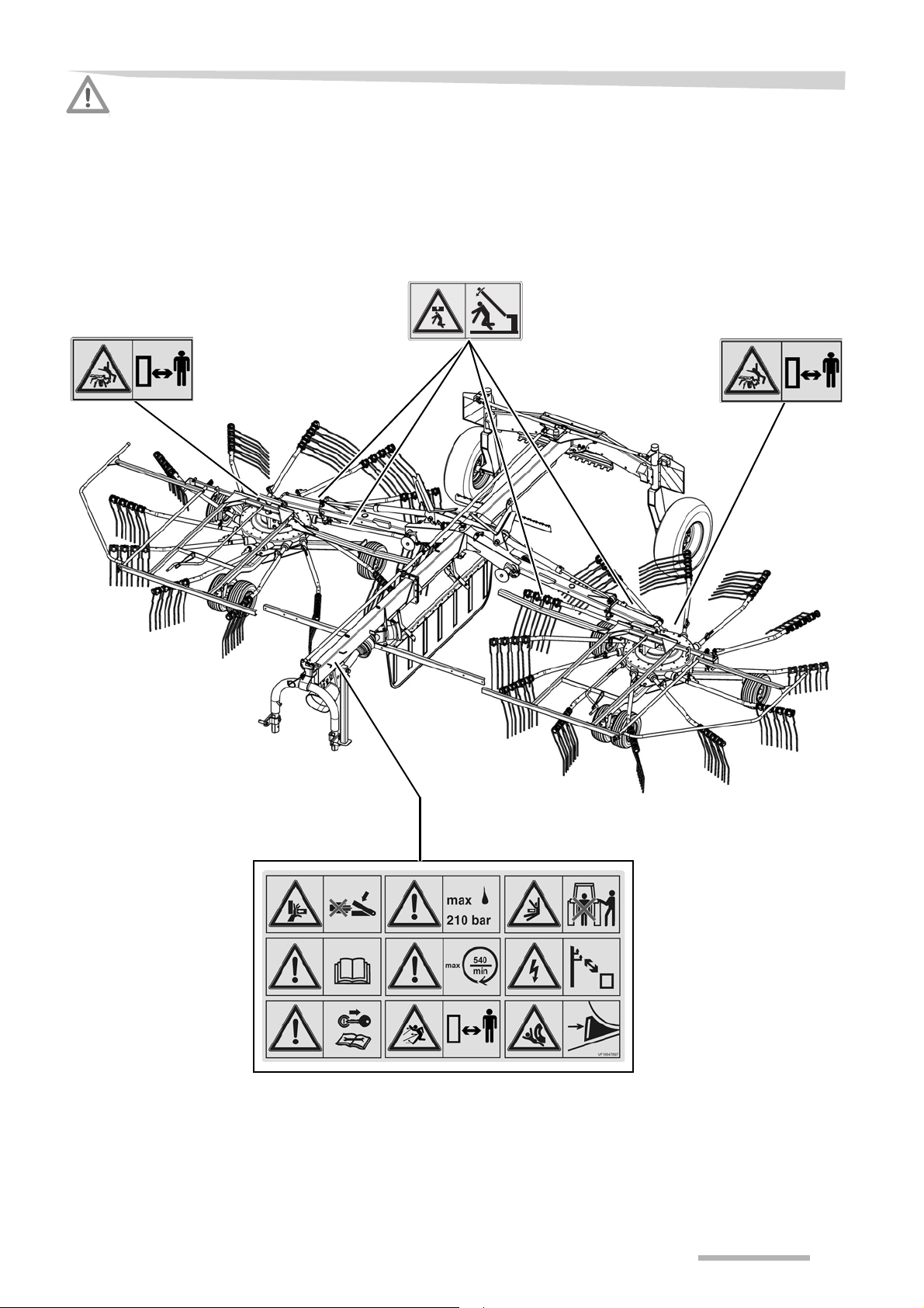
Warning signs
Warning signs on the
machine
Safety-related labels attached to the machine indicate potential
hazards. The labels must not be removed. Illegible or missing labels
should be replaced. You can obtain new labels as spare parts from
your dealer.
7
Page 8
Safety
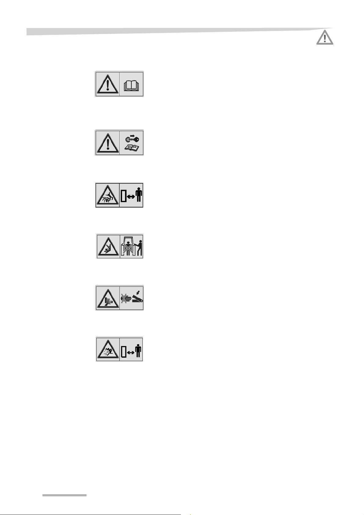
Meaning of the warning
signs
Read the operating manual
Read and follow the operating and safety instructions before using the
machine for the first time. The machine must not be used for the first
time until the operating manual has been read and understood. This
applies in particular to the safety information. Otherwise, serious or
fatal injury may be caused as a result.
Switch off the engine
Only perform maintenance, repair and adjustment work when the
machine is shut down. Otherwise, serious or fatal injury may be
caused as a result.
Distance from the rotor
Maintain a safe distance from the rotor when it is rotating. Nobody may
remain in close proximity to the machine when rakes and swathers are
running. Otherwise, serious or fatal injury may be caused as a result.
Distance from tractor
When the machine is being coupled, uncoupled or operated, there
should be no-one between the tractor and the machine. Otherwise,
serious or fatal injury may be caused as a result.
Risk of crushing
Never reach into an area where there is a risk of crushing if parts in
that area are still likely to move. Otherwise, serious or fatal injury may
be caused as a result.
Caution, parts ejected at speed
Hazard caused by parts which may become detached when the drive
is in operation, and ejected at speed. Maintain a safe distance.
Otherwise, serious or fatal injury may be caused as a result.
8
Page 9
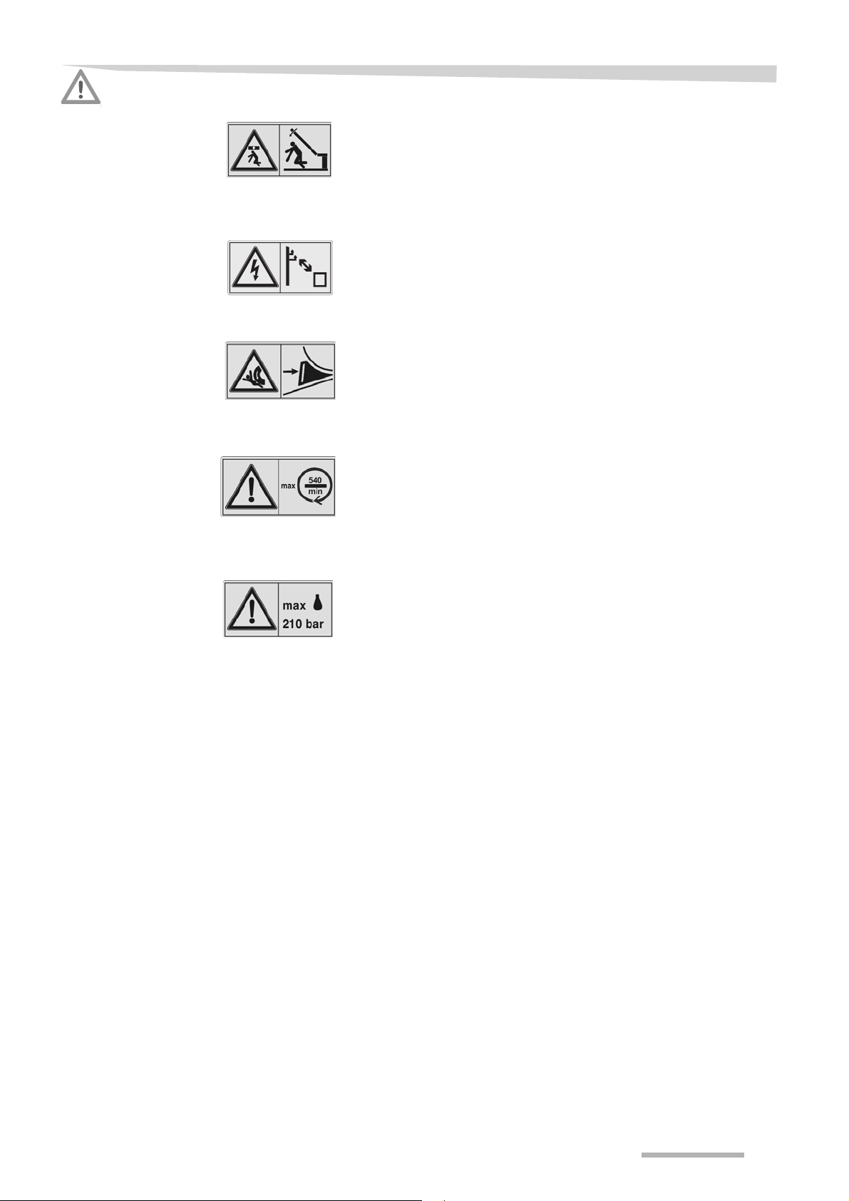
Safety
No persons within the slewing range
There is an acute risk of injury within the slewing range from machine
parts which are slewing or folding. Otherwise, serious or fatal injury
may be caused as a result.
Caution, high voltage
Maintain a sufficiently safe distance from high-voltage lines.
Otherwise, serious or fatal injury may be caused as a result.
Secure the machine with wheel chocks
Always secure the machine with wheel chocks to ensure it cannot roll
away when it is in park or stop position. Otherwise, serious or fatal
injury may be caused as a result.
PTO shaft speed 540 rpm
The specified maximum PTO shaft speed of 540 rpm must not be
exceeded. Otherwise, damage to the machine may be caused as a
result.
Do not exceed the maximum hydraulic pressure
The tractor's hydraulic pressure on the machine's hydraulic system
must not exceed 210 bar. Otherwise, damage to the machine may be
caused as a result.
9
Page 10

Safety
Who is allowed to
operate the
machine?
General safety information
Only qualified personnel
Only qualified persons who have been informed of the dangers
associated with handling the machine are permitted to operate,
service or repair the machine. The necessary knowledge can be
gained in the course of agricultural vocational training, professional
training or intensive instruction.
The general safety information and warning signs apply to every
phase of the life cycle of the machine and to every application.
Switch off the tractor and secure it
Before you dismount:
Switch off the tractor.
Remove the ignition key.
Secure the tractor against rolling away.
An unsecured tractor can run you over or trap you. Serious or fatal
injury may be caused as a result.
Operate for the first time only after proper training
The machine may only be put into operation after proper training has
been provided by an employee from a dealership or the manufacturer,
or by a factory representative. Operation without proper training can
lead to damage to the machine due to incorrect operation, or may
cause accidents.
Safety is your responsibility
Follow the safety regulations. Ensure that all operators comply with
the safety instructions. Prevent serious or fatal accidents by following
the safety instructions.
Instructions in the event of malfunctions
In the event of a malfunction, stop, shut down and secure the machine
immediately. Rectify the malfunction immediately yourself or seek the
assistance of a workshop. Operating a faulty machine can cause
accidents or damage.
No persons in the working area
Ensure that no persons are present in the slewing and working area
of the machine. Persons could be caught by the machine within this
area. Fatal injury may be caused as a result.
Perfect working condition
Ensure that the tractor and the machine are always in perfect working
condition. Make sure that the tractor brakes work in conjunction with
the machine. Also follow the instructions in your tractor's operating
manual.
10
Page 11

Safety
Switch off the PTO shaft drive when raising the machine
Switch off the PTO shaft drive on the tractor if people could enter the
working area of the machine when you
• raise the machine,
• raise the side devices or
• raise the rotors to the headland position.
Rotating, unprotected parts can damage the machine and cause lifethreatening injuries.
Switch off the tractor PTO shaft drive
Switch off the PTO shaft drive on the tractor when changing from work
to transport position (and vice versa). Wait for the moving parts to stop
moving. If this requirement is ignored, the consequence may be
damage to the machine and even life-threatening injuries.
No reversing while the drive is running
Never drive in reverse with the PTO shaft drive switched on and in the
work position if people could enter the working area of the machine.
Switch off the PTO shaft drive. Rotating, unprotected parts can
damage the machine and cause life-threatening injuries.
Specified workwear
Do not wear loose fitting clothing. Loose fitting items of clothing may
become caught in rotating parts. Wear workwear and protective
clothing, as specified by the Accident Prevention and Insurance Association. Serious or fatal injury may be caused as a result.
No riding on the machine
Persons or objects must never be transported on the machine.
Carrying passengers on the machine is life threatening and prohibited.
Serious or fatal injury may be caused as a result.
11
Page 12

Safety
Never work on the machine while it is running
No operations may be performed on the machine while it is running.
Objects or persons can be caught, drawn in or crushed. Serious or
fatal injury may be caused as a result.
Safety distance from raised and unsecured loads
Never work under suspended loads. Maintain a sufficient distance
from raised and unsecured loads. Otherwise, serious or fatal injury
may be caused as a result.
PTO shaft
Use only the PTO shafts specified by the manufacturer and read the
attached operating manual carefully. Adjust the length of the PTO
shaft as required. Incorrect PTO shaft lengths can cause damage to
the machine and personal injury.
Check and fasten the PTO shaft guard in position
The rotating PTO shaft is protected by the PTO shaft guard. Ensure
that the guard is not damaged. Fasten the PTO shaft guard in position
by connecting the chains on the implement and the tractor. Unguarded
PTO shafts can cause life-threatening injuries.
Make sure the machine is standing level
Before changing from the transport to the work position (and vice
versa), make sure the machine is standing level. The machine could
tip over, particularly on hillside locations. Otherwise, damage to the
machine and serious or fatal injury may be caused as a result.
Do not make any modifications to the machine
No modifications of any kind may be made to the machine. Unauthorised modifications can adversely affect the correct operation and
safety of the machine and shorten its service life. Unauthorised modifications to the machine render the manufacturer's guarantee null and
void and free the manufacturer from all liability.
12
Page 13

Safety
PTO shaft speed 540 rpm
The specified maximum PTO shaft speed of 540 rpm must not be
exceeded. A higher PTO shaft speed will damage the machine.
Only use the PTO shaft specified
Only use PTO shafts which have been specified by the manufacturer.
Other PTO shafts with disconnect couplings may allow higher
disconnect torques. Higher disconnect torques may damage the
machine.
Unrestricted field of vision to the rear
After it has been coupled, ensure that you have an unrestricted view
of the machine, in both its work and transport positions. At the very
least, use the panorama mirror provided by the tractor manufacturer.
Otherwise, hazardous situations may not be detected in time, and
accidents or damage may be caused as a result.
Check the angle of lock
On machines with attachment carriers, an angle of lock of 90° is
possible. This angle must not be exceeded. Otherwise, damage to the
PTO shaft may be caused as a result.
13
Page 14

Safety
Coupling
Increased risk of injury
When the machine is being coupled to the tractor, there is an
increased risk of injury. Therefore:
• Secure the tractor against rolling away, shut off the engine and
remove the ignition key.
• Never stand between the tractor and machine.
• Lock the PTO shaft securely to the PTO stub shaft on the tractor
and the machine.
If this requirement is ignored, the consequence may be damage to the
machine and even life-threatening injuries.
Attaching electrical connections after assembly
The electrical supply to the tractor must not be connected when the
lighting equipment is being fitted. Otherwise, short circuits may occur
and the electronic system may be damaged.
Observe the operating manual of the PTO shaft manufacturer
Observe the operating manual of the PTO shaft manufacturer. It will
provide you with instructions on how to handle the PTO shaft correctly.
If these instructions are ignored, damage may be caused to the PTO
shaft and machine.
Risk of tipping due to unsecured quick-release couplings
When the machine is coupled to tractors with lower link quick-release
couplings, the latter must be secured against unintentional opening. If
the quick-release couplings open unintentionally, the tractor and
machine may tip over. If this requirement is ignored, the consequence
may be damage to the machine and even life-threatening injuries.
Also follow the instructions in your tractor's operating manual.
14
Page 15

Safety
Hydraulics
Hydraulic connection at zero pressure only
Only connect hydraulic hoses to the tractor hydraulic system if the
tractor and machine hydraulic system is at zero pressure. A
pressurised hydraulic system can trigger unforeseen movements on
the machine and can cause serious machine damage and personal
injury. Serious or fatal injury may be caused as a result.
High pressures in the hydraulic system
The hydraulic system is under high pressure. Regularly check all lines,
hoses, and screwed connections for leaks and externally visible
damage. Only use suitable tools when looking for leaks. Rectify any
damage immediately. Oil escaping under pressure may result in
injuries and fires. Seek medical attention immediately if injuries occur.
Replace hydraulic hoses every six years
Hydraulic hoses age without showing externally visible signs. Replace
hydraulic hoses every six years. Defective hydraulic lines can cause
serious or fatal injuries.
15
Page 16

Safety
Road transport
Ensuring road safety
The machine must conform to current national traffic regulations if you
intend to drive with it on public roads. Ensure the following:
• Lighting, warning and protective equipment must be fitted.
• The permissible transport widths and weights, axle loads, tyre
load-bearing capacities, laden weights and national speed restrictions must be complied with.
• The maximum permissible road transport speed of 50 km/h must
be complied with.
• Before driving on public roads, fold in all deflector bars and rotors
and secure the machine.
• All tine supports which have tips that point at right angles to the
direction of travel and which are at a height of less than 2 metres
must be safeguarded using the tine covers provided, or otherwise
detached.
• The machine should only be towed by agricultural or forestry
tractors.
The empty weight of the tractor must be greater than the weight of the
machine. The driver and keeper of the vehicle are liable should these
conditions not be observed.
Close the ball valve
Close the ball valve before driving on the road. If the ball valve is open
and there is an operating error, the machine may drop or swing out unexpectedly. This could cause traffic accidents and accidents with fatal consequences.
Check the tyre pressure
Check tyre pressure on a regular basis. Incorrect tyre pressures
reduce the service life of a tyre and cause unstable driving characteristics. Accidents with serious or fatal injuries may be caused as a
result.
Altered driving and braking performance
Driving and braking characteristics are altered when the machine is
coupled or hitched to the tractor. When cornering, take the overall
width and balancing weight of the machine into consideration. Adapt
your driving speed accordingly. A driving style which is not adapted to
conditions can cause accidents. Accidents with serious or fatal injuries
may be caused as a result.
16
Page 17

Safety
Speed adjustment
In poor road conditions and at high speeds, powerful forces can be
generated that subject the tractor and machine material to high or
excessive stresses. Adjust your driving speed to the road conditions.
A driving style which is not adapted to conditions can cause accidents.
Accidents with serious or fatal injuries may be caused as a result.
Check hitch pins
Hitch pins must be in perfect condition. Hitch pins must show no signs
of wear and be properly secured. Otherwise, hitched machines may
detach themselves of their own accord. Accidents with serious or fatal
injuries may be caused as a result.
Check release cords on quick release couplings
Release cords must hang loose and must not allow a release in their
lowered position. Hitched machines may otherwise detach
themselves from the lower link hitching system of their own accord.
Accidents with serious or fatal injuries may be caused as a result.
17
Page 18

Safety
Operation
Operate for the first time only after proper training
The machine may only be put into operation after proper training has
been provided by an employee from a dealership or the manufacturer,
or by a factory representative. Operation without training can lead to
damage to the machine due to incorrect operation, or cause
accidents.
Ensure that the machine is in perfect working condition
Do not operate the machine unless it is in perfect working condition.
Check all key components and their operation before use. Replace
defective components. Defective components can cause material
damage and personal injury.
Check the protective equipment
The protective equipment must not be removed or by-passed. Check
all protective equipment before using the machine. Unprotected parts
of the machine can cause serious or fatal injury.
Check the immediate vicinity
Check the area immediately surrounding the machine before driving
off, and continually during operation. Make sure that you have an
adequate view. Only begin work when the immediate vicinity is cleared
of any persons or objects. Serious or fatal injury may be caused as a
result.
Retighten all nuts, bolts and screws
Regularly check that bolts and nuts are correctly tightened. Retighten
bolts if necessary. Nuts and bolts can work loose when the machine is
used. Otherwise, the machine may be damaged or accidents caused
as a result.
Tractor PTO stub shaft continues to turn after being switched off
After the PTO shaft drive on the tractor has been switched off, the
machine continues to run due to the moment of inertia. Maintain a
sufficient safety distance until all moving parts have come to a
complete standstill. Otherwise, damage to the machine and serious or
fatal injury may be caused as a result.
Cornering and turning manoeuvres
Centrifugal forces are in operation during cornering. The machine's
centre of gravity at the rear of the tractor is displaced. Be aware of the
turning radius and the moment of inertia. A driving style which is not
adapted to conditions can cause accidents. Accidents with serious or
fatal injuries may be caused as a result.
18
Page 19

Safety
Uncoupling
Increased risk of injury
There is an increased risk of injury when uncoupling the machine from
the tractor. Therefore:
• Set the machine down on firm, secure and level ground.
• Never stand between the tractor and the machine during manoeu-
vring.
• Secure the tractor against rolling away, turn off the engine and
remove the ignition key.
• Secure the machine against rolling away (use wheel chocks).
• Ensure that the sustainer is securely locked.
• Place the PTO shaft in the holder provided.
• Do not uncouple the hydraulic hoses until the hydraulic system is
at zero pressure.
Failure to observe these instructions can result in serious or fatal
injury.
19
Page 20

Safety
Care and maintenance
Observe the care and maintenance intervals
Observe the periods specified in the operating manual for recurrent
checks and inspections. If these periods are not observed, damage to
the machine and accidents may be caused as a result.
Use original parts
Many components have special properties that are decisive for the
stability and correct operation of the machine. Only spare parts and
accessories supplied by the manufacturer have been tested and
approved. Other products may disrupt the correct operation of the
machine and adversely affect safety. Using non-original replacement
parts renders the manufacturer's guarantee null and void and frees the
manufacturer from all liability.
When performing care and maintenance work:
• Switch off the PTO shaft drive.
• Depressurise the hydraulic system.
• Whenever possible, uncouple the tractor.
• Switch off the tractor and remove the ignition key.
• Ensure the machine is standing on firm, secure and level ground,
and provide additional support, if necessary.
• Secure the machine against rolling away (use wheel chocks).
Only if these regulations are observed can safe working be ensured
during care and maintenance work.
Turn off the electrical supply
Prior to carrying out work on the electrical system, disconnect the
system from the power supply. Systems being supplied with electrical
power can cause damage to equipment and injury to persons.
Caution when cleaning with a high-pressure cleaner
Exercise caution when cleaning with a high-pressure cleaner.
Bearings, seals and pipe unions are not waterproof. In order to
prevent damage to the machine, the bearings, seals and pipe unions
must not be exposed to direct contact with the high pressure water
jets.
20
Page 21

Safety
No aggressive washing additives
Do not use any aggressive washing additives for cleaning. Uncoated
metal surfaces can be damaged.
Before carrying out welding work
Disconnect all electrical connections from the tractor when carrying
out welding on the hitched machine. Damage may otherwise be
caused to the electrical system.
Retighten all nuts, bolts and screws
All screwed/bolted connections that are loosened during maintenance
and repair operations must be retightened. Serious injury and damage
to equipment can be caused by loose pin and screw connections.
Further regulations
Warranty
Observe the regulations
In addition to the safety information given above, please observe the
following:
• Accident prevention regulations.
• Generally recognised safety regulations, occupational health
requirements and road traffic regulations.
• The instructions provided in this operating manual.
• Regulations relating to operation, maintenance and repair.
The warranty and manufacturer's liability will no longer be valid if the
instructions provided in the chapter on Safety are not observed, if
maintenance is inadequate or faulty, if the machine is used for
purposes other than those for which it was intended and if it is overstressed, or if impermissible modifications are made to the machine.
21
Page 22

Getting to know the machine
Getting to know the machine
Range of application
Proper use
Features
This product is classified as replaceable equipment in accordance
with EC directive 2006/42/EC.
The machine is a twin rotor swather, which is suitable only for the
raking together of mowed stalk-type vegetation (for example, hay or
straw).
Any other use, for example, for silo distribution, any form of soil preparation, road sweeping or for the transmission of power to other
machines, is not permitted. The manufacturer and dealers are not
liable for damage caused by improper use. The risk is borne solely by
the user.
Flexible in operation
This central rake, which has a working width of approximately 8.40
metres, meets all the requirements of modern crop harvesting engineering. All the important functions for field use are controlled during
operation. The following functions can be set:
• Deposit of crop in single rotor operation via the hydraulic single lift.
• Individual working depth of both rotors.
• Swath width.
The rake can be pulled by tractors of 40 kW (56 hp) or more.
Extensive equipment
The machine is equipped with low-maintenance gearboxes and 11
arms on each rotor. The offset tines provide excellent raking quality.
The “TerraLink” support ensures outstanding adjustment to the
contours of the land.
The swath former swivels into the selected transport or work position.
Easy changeover from work to transport position
The swather is easily changed over from the work to the transport
position. Hydraulic cylinders lift the rotors into the transport position to
maintain the transport width of less than 2.80 m.
22
Page 23
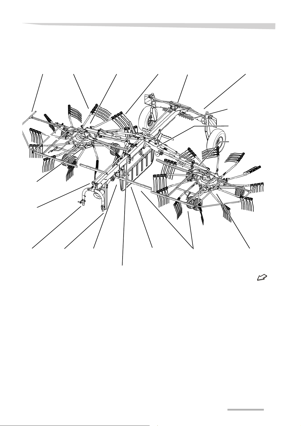
Component
Deflector bar
Main frame
Attachment
carrier
Deflector barDrive
Tine support Tines
Swath former
Rotor gear Transport chassis
Rotor chassis
Transport holder for
tine supports
Sustainer
Steering
Tine arm shaft
Telescopic arm
Lifting arm
Tine cover stowage
area
designations
Getting to know the machine
23
Page 24
Getting to know the machine
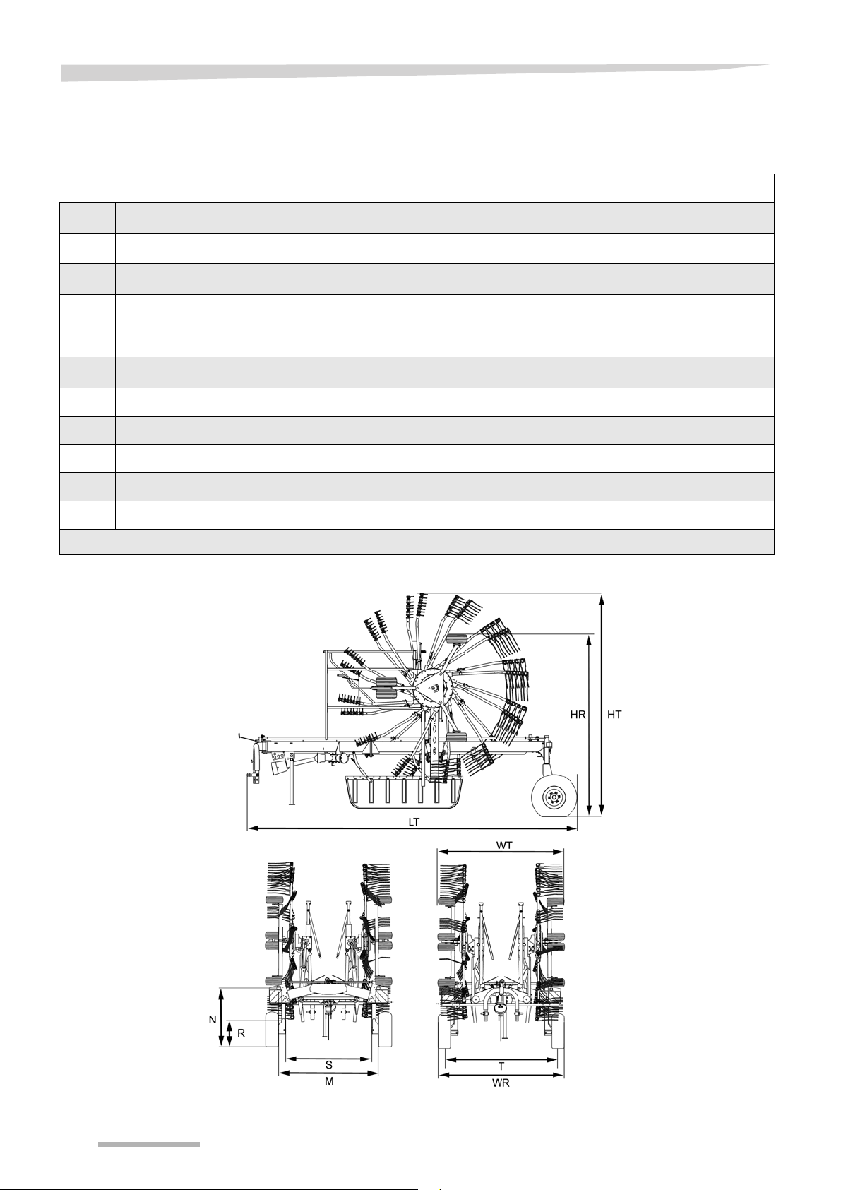
Technical specifications
Dimensions Transport position [m]
L
T
H
T
H
R
W
W
T Track width 2.61
M Distance between lights 2.30
N Height of lights 1.29
R Height of bottom reflectors 0.35
S Distance between bottom reflectors 2.08
** Machine attachment carrier (cat. 2) lowered to 20 cm from the ground.
Length
Height with mounted tine supports
Height without the upper tine supports for transport position
Width without the upper tine supports for transport position when using
tyres
R
11.5/80-15.3 and 380/55-17.
Maximum width with mounted tine supports
T
6.24
4.10* - 4.25
3.44*
2.89 and 2.98
2.98
24
Page 25
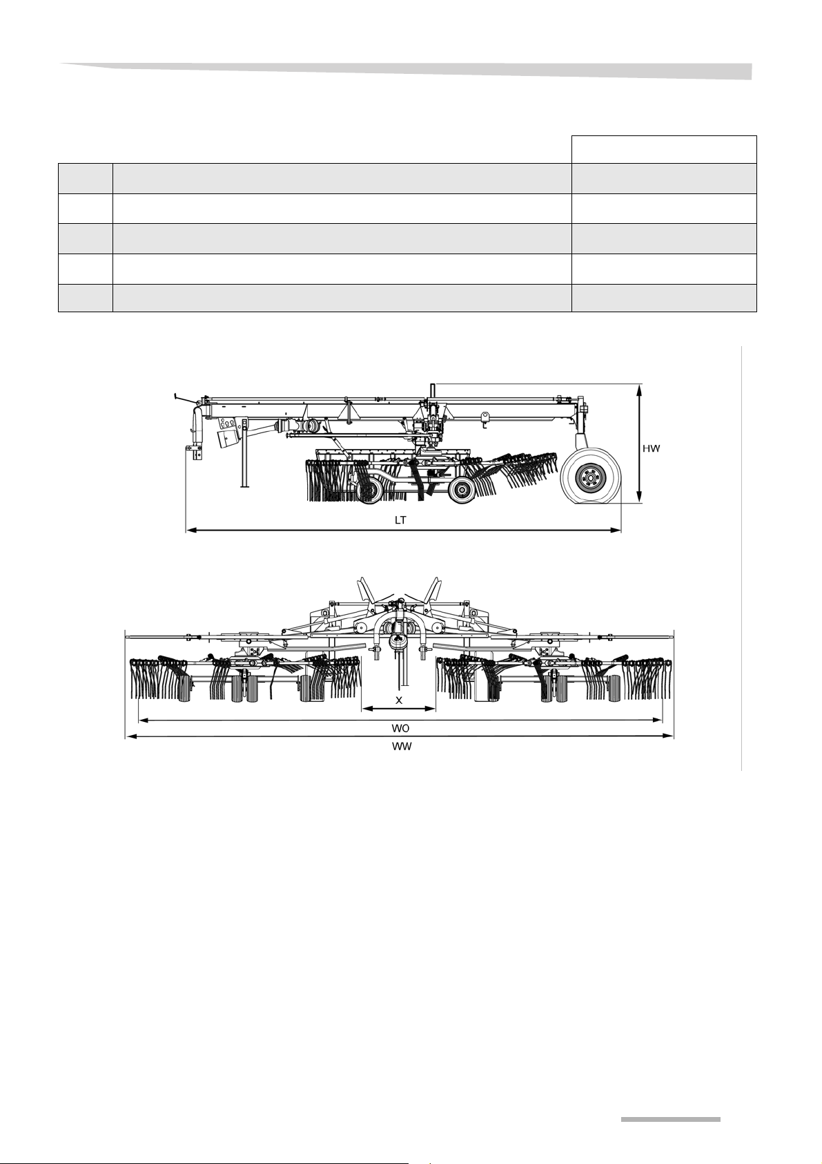
Getting to know the machine
Dimensions Work position [m]
L
T
H
W
W
W
X Distance between the rotors 0.30-1.15
Length
Height in work position
Working width
W
Raking width
O
6.24
1.50
7.60 - 8.40
8.50
25
Page 26

Getting to know the machine
Weights
Work position [kg] Transport position [kg]
Total weight 1950
Load supported on lower link - 755
- 119 5
Transport chassis axle load
Tractor equipment
required
Output / connections
Minimum output of the tractor 40 kW (56 hp)
Lighting power supply 12 V, 7-pin plug socket ISO 1724
(based on load supported on lower
link)
Hydraulic connections
Hydraulic pressure 150 - 210 bar
Maximum PTO shaft speed 540 rpm
Lower link Fixable in height and laterally
1 x double-acting hydraulic control unit
1 x single-acting hydraulic control unit
26
Page 27

Machine equipment
Swath deposit
Swath former with auto-swivel Standard
Rotors/tine supports/tines
Number of rotors 2
Getting to know the machine
Number of tine supports per rotor
Number of tines per tine support 4
Removable tine arms Standard
Rotor height adjustment Mechanical
Hydraulic single lift [+]
Tine saver [+]
Wheels
Rotor chassis 16 x 6.50-8 6 PR
Tandem axles on rotor chassis [+]
Transport chassis
Safety accessories
Lighting equipment Standard
Warning plates Standard
PTO shaft
12 swaths on the left
12 swaths on the right
11.5/80-15.3 or
380/55-17 [+]
PTO shaft with freewheel Standard
Airborne sound
emissions
measurement
The airborne noise emissions from the machine are – according to
Machinery Directive 2006/42/EC – below the required levels.
• A-weighted sound level in the workplace:
< 70 dB(A)
• Currently C-weighted sound level:
< 63 Pa (130 dB based on 20 µPa)
• A-weighted sound level on the machine:
< 80 dB(A)
27
Page 28
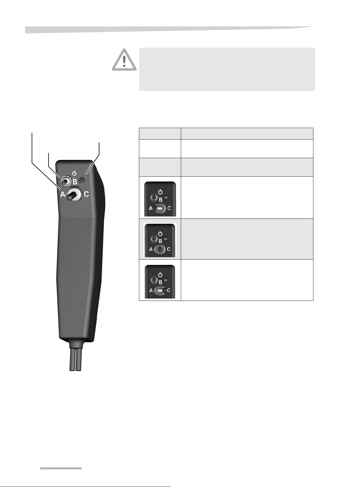
Getting to know the machine
On/Off switch
Control LED
3-way switch
Pilotbox [+]
Protect electrical parts against moisture
The electronic control system, pilotbox [+] and electrical plug connections must be protected against damp and penetrating moisture. Dampness in electronic devices can lead to leakage current,
which results in malfunction.
Using the electro-hydraulic operator control unit, the pilotbox [+], the
following functions can be selected and executed using a single-acting hydraulic control unit:
Preselection Function
Pilotbox
OFF
Pilotbox
ON
Raise and lower both rotors.
Control LED lights up. The A and C functions are
available.
A: Raise and lower the left rotor.
B: No function.
C: Raise and lower the right rotor.
Operate the rotary rake with the pilotbox [+] as follows:
Mount the pilotbox [+] in the tractor cab so that it is secure and
easily reachable.
Switch it on and off with the switch. The control LED lights up when
the pilotbox [+] is switched on.
With the switch, select the function (A, B or C) and then execute
the function with the single-acting hydraulic control unit.
28
Page 29
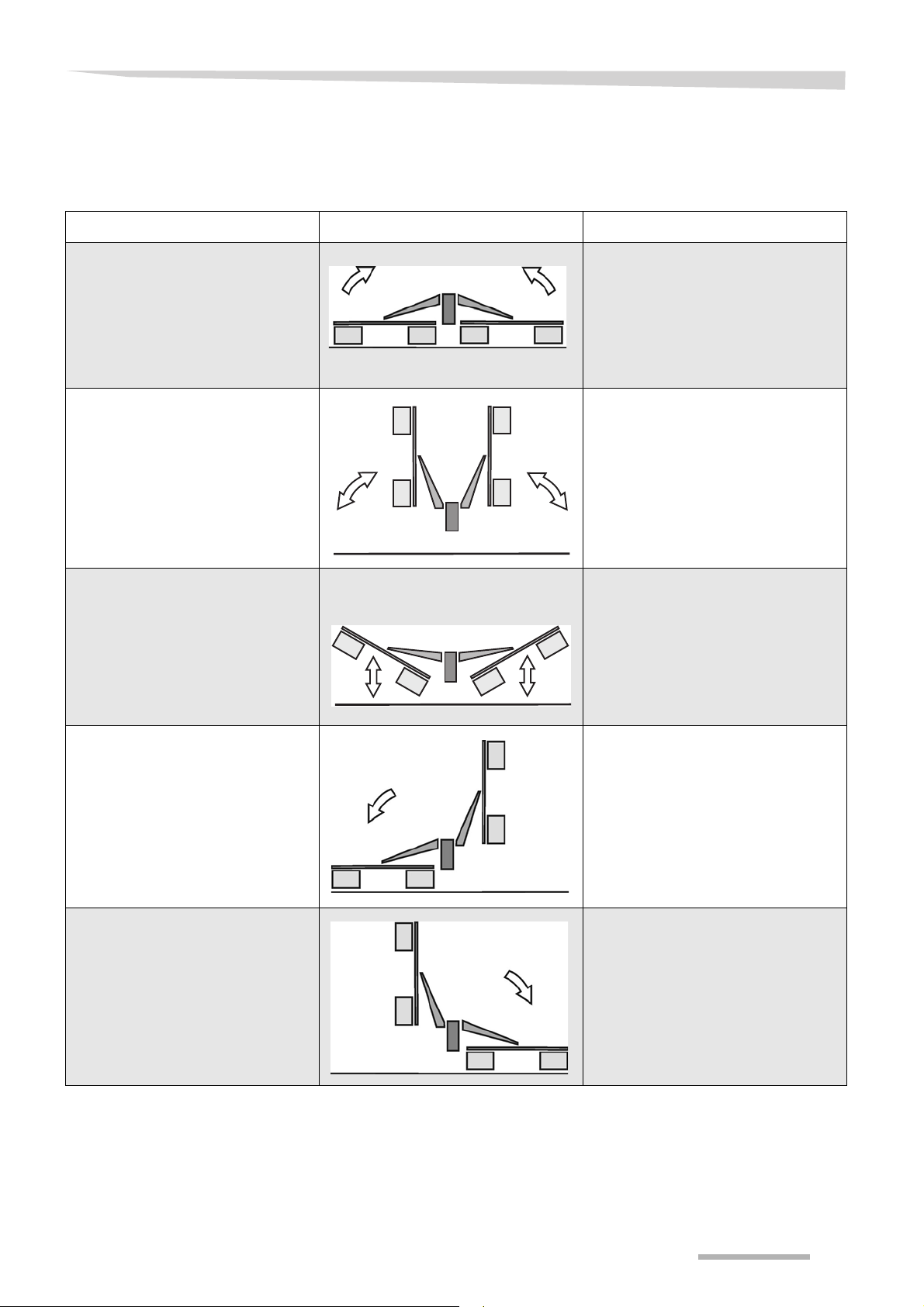
Getting to know the machine
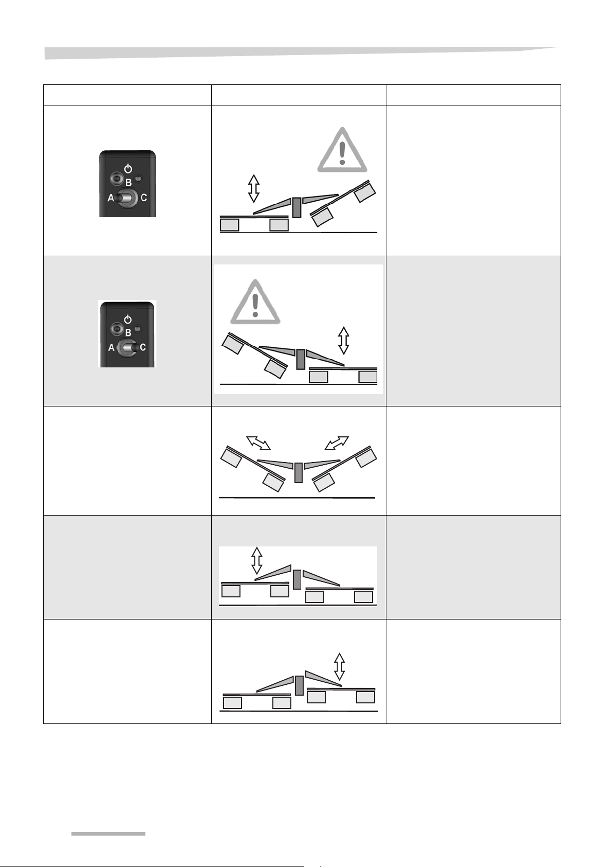
Function
overview
Steering Machine position Function
• Single-acting hydraulic control
unit on the tractor.
• Single-acting hydraulic control
unit on the tractor.
• Single-acting hydraulic control
unit on the tractor.
The table below provides a summary of the functions. Be sure to
follow the other instructions and note the safety information in the
operating manual.
Transport
• Machine in work position.
• Switch off the PTO shaft drive.
• Cover and/or remove outer tine arms
for transportation.
• Clean the machine.
• Use the single-acting hydraulic
control device on the tractor to move
the machine to the transport position.
• Remove inner tine arms for transport.
Work position
• Switch off the PTO shaft drive.
• Use the single-acting hydraulic
control device on the tractor to
release the lifting arm locking
mechanism.
• Pull the cord on the mechanical lock
and keep tensioned.
• Fold the rotors in fully with the single-
acting hydraulic control device on the
tractor.
Headlands
• Using the tractor's single-acting
hydraulic control unit, raise both
rotors to the headland position, then
lower them.
• Single-acting hydraulic control
unit on the tractor.
• Mechanical locking
mechanism cable.
• Single-acting hydraulic control
unit on the tractor.
• Mechanical locking
mechanism cable.
Lowering the left rotor
• Remove the right side shaft.
• Raise the machine to the transport
position using the single-acting
hydraulic control unit until the lift
arms lock.
• Pull the mechanical locking
mechanism cable of the left rotor.
• Lower the left rotor using the single-
acting hydraulic control device on the
tractor.
Lowering the right rotor
• Remove the left side shaft.
• Raise the machine to the transport
position using the single-acting
hydraulic control unit until the lift
arms lock.
• Pull the mechanical locking
mechanism cable of the right rotor.
• Lower the right rotor using the single-
acting hydraulic control device on the
tractor.
29
Page 30
Getting to know the machine
Steering Machine position Function
• Pilotbox [+] is switched on.
• Preselect position "A" on the
pilotbox [+].
• Single-acting hydraulic control
unit on the tractor.
• Pilotbox [+] is switched on.
• Preselect position "C" on the
pilotbox [+].
• Single-acting hydraulic control
unit on the tractor.
Swathing with left rotor [+]
• Switch on pilotbox [+].
• Preselect position "A" on the
pilotbox [+].
• Using the tractor's single-acting
hydraulic control unit, raise the right
rotor and then lower it.
Swathing with right rotor [+]
• Switch on pilotbox [+].
• Preselect position "C" on the
pilotbox [+].
• Using the tractor's single-acting
hydraulic control unit, raise the left
rotor and then lower it.
• Double-acting hydraulic control
unit on the tractor.
• Single-acting hydraulic control
unit on the tractor.
• Crank on left rotor.
• Crank on right rotor.
Swath width
• Raise the machine into the headland
position using the tractor's singleacting hydraulic control unit.
• Adjust the swath width using the
double-acting hydraulic control
device on the tractor.
• Lower the machine to the work
position using the tractor's singleacting hydraulic control unit.
Working depth of left rotor
• Switch off the PTO shaft drive.
• Switch off the tractor and secure it.
• Set the working depth using the crank
on the left rotor.
Working depth of right rotor
• Switch off the PTO shaft drive.
• Switch off the tractor and secure it.
• Set the working depth using the crank
on the right rotor.
30
Page 31

Delivery and assembly
Delivery and assembly
Checking the scope of delivery
Delivery is in the fully assembled state
The machine is delivered fully assembled. Using the checklist, check
the loose parts on delivery. If any parts of the machine have not been
fitted or are missing, please contact your dealer.
Do not assemble the machine yourself.
Trained personnel are required to assemble the machine. Do not
perform assembly work yourself. The following points are required
to be met for the machine to be in proper condition:
• Observance of a sequence of work steps.
• Compliance with tolerances and torques.
• Knowledge of work safety during assembly.
Incorrect assembly can result in damage to the machine or
accidents.
If parts are missing or have been damaged during transportation,
please inform the dealer, importer or manufacturer immediately.
Checklist for parts which were
supplied loose
PTO shaft for drive 1
PTO shaft for auxiliary drive
(side shaft)
Quantity
2
Tine supports placing swaths on the
left
Tine supports placing swaths on the
right
Swath former 1
Wheel chock 2
Warning sign and lighting equipment
set
Operating manual 1
Spare parts list 1
Additional equipment See delivery note
12
12
1
31
Page 32

Delivery and assembly
Checking the length of the PTO shaft
The length of the PTO shaft has been selected at the factory to suit
almost all types of tractor. Only in exceptional cases is a correction of
the PTO shaft length required on individual tractors. Check the length
of the PTO shaft for each tractor prior to first use.
The operating manual from the PTO shaft manufacturer is included.
This includes detailed information on the relevant version of the PTO
shaft and must be observed.
Switch off the tractor and secure it
Before you dismount:
Switch off the tractor.
Remove the ignition key.
Secure the tractor against rolling away.
An unsecured tractor can run you over or trap you. Serious or fatal
injury may be caused as a result.
Check the angle of lock
The tractor's PTO shaft has a wide hinge joint, allowing an angle
of lock of up to 80°. Make sure that the PTO shaft is not damaged
during sharp cornering. The machine may be damaged as a
result.
Correct length
A PTO shaft which is too long must not be used. Otherwise,
damage to the drive bearings on the tractor and machine may be
caused as a result.
Couple the machine to the tractor without the PTO shaft.
Lower the tractor's lower link.
Set the tractor and machine to the smallest angle of lock.
Secure the tractor against rolling away, shut off the engine and
remove the ignition key.
32
Page 33

Shortening the PTO
Marks on the guard tube
shaft
Delivery and assembly
Pull the PTO shaft apart and connect one half to the tractor PTO
shaft drive and one to the machine and secure them.
Place the two shaft halves next to each other and:
• Check for a minimum of 250 mm overlap (b).
• Check that the PTO shaft is not resting on the block
(minimum clearance (a) = 20 mm).
Shorten both the sliding tube and guard tube to the same size.
Deburr the ends of the tubes.
Remove the swarf.
Grease the sliding surfaces well.
Fitting the PTO shaft
Make sure that you fit the PTO shaft in the correct installation position.
There is a mark on the guard tube of the PTO shaft.
Check the length of the PTO shaft and shorten it if necessary.
Fit the PTO shaft onto the machine's PTO stub shaft.
Secure the PTO shaft with a locking pin.
33
Page 34

Delivery and assembly
Track arm
Steering arm
Track rod
Steering rod
Checking the steering
Never carry out work on the steering
Contact your dealer if specifications differ. Never carry out any work
on the steering or track yourself. There is otherwise the risk of traffic
accidents and accidents with fatal consequences.
The steering is fitted and calibrated in the factory.
Check the adjustment with a hitched machine
Drive along a straight line with the entire combination (tractor with
hitched machine).
Check if the machine runs in a straight line behind the tractor.
When driving in a straight line, if the machine swerves to the side or if
the wheels do not run parallel, the track and steering must be
readjusted at an authorised workshop.
Check if the target measurements are correct.
If discrepancies are found, consult your dealer.
See chapter »Checking the track«, page 90.
34
Page 35

Coupling the machine
Safety
Coupling the machine
Observe the safety information
Observe the safety information. Disregard for safety information
can lead to serious or fatal injury. See chapter »Safety«, page 6.
Increased risk of injury
When the machine is being coupled to the tractor, there is an
increased risk of injury. Therefore:
• Never stand between the tractor and machine.
• Secure the tractor against rolling away.
• Slowly and carefully actuate the three-point power lift system.
Failure to observe these instructions can result in serious or fatal
injury.
General
The machine is equipped at the factory for coupling to the lower link of
the three-point power lift system.
The following work steps are described in this section:
• »Coupling the lower link«
• »Swivelling in the parking stand«
• »Coupling the PTO shaft«
• »Wheel chocks«
• »Electrical connections«
• »Hydraulic connections«
35
Page 36
Coupling the machine
Pin
Lynch pin
Catch
Lower link
Coupling the lower link
Tractors with quickrelease couplings
Follow the instructions for the quick-release coupling
Follow the instructions below for tractors with quick-release
couplings. Also note the instructions and warnings in the operating
manual of the tractor manufacturer.
If this requirement is ignored, the consequence may be damage to
the machine and even life-threatening injuries.
The following applies to tractors with quick-release couplings:
Slide collecting trays suitable for the tractor onto the lower link
hitching system of the machine.
To couple the machine, raise the lower link until the catch engages.
Secure the quick-release coupling with linchpins.
Secure the catch with pins.
Follow the instructions for »Tractors without quick-release
coupling«.
Tractors without
quick-release
coupling
The following applies to all tractors - with or without quickrelease couplings:
Couple the machine to the lower link - in accordance with the
operating manual of the tractor manufacturer - lift slightly and
secure.
Slightly raise the lower link.
Secure the tractor against rolling away, shut off the engine and
remove the ignition key.
Swivel in the sustainer.
See »Swivelling in the parking stand«, page 37.
With the lower link in the work position, lift it off the ground until the
main frame of the machine is tilted approximately 1 degree
forwards.
Engage the lower link at the sides.
Adjust the lower link such that a uniform ground clearance is
maintained.
36
Page 37
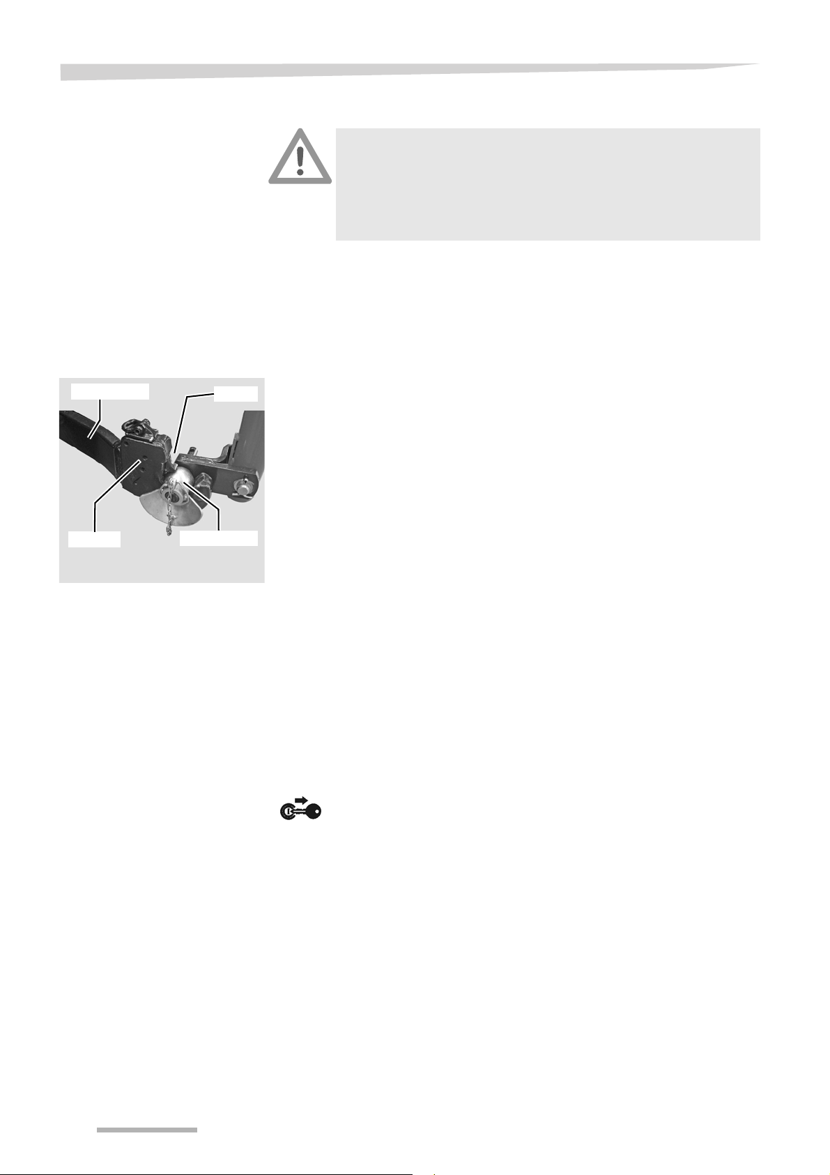
Swivelling in the
Pin
Sustainer
parking stand
Coupling the machine
After coupling the machine to the tractor, raise and secure the
sustainer.
Switch off the tractor and secure it, shut off the engine and remove
the ignition key.
Pull out the pins in the sustainer.
Swivel in the sustainer.
Undo the pins on the sustainer and engage them.
37
Page 38

Coupling the machine
PTO shaft
Chain
Wide angle joint
Tractor
Wide angle joint with
freewheel assembly
Coupling the PTO shaft
When coupling the PTO shaft, make sure it is in the correct position.
Check whether the PTO shaft must be shortened before coupling.
Shorten the PTO shaft if necessary.
»Checking the length of the PTO shaft«, page 32
Check that the tractor's PTO stub shaft is clean and lubricated.
Couple the PTO shaft to the tractor and the machine.
Ensure that the PTO shaft is engaged on the shaft ends.
Secure the guard tubes so that they cannot rotate at the same
time.
Couple the wide-angle joint to the machine's PTO stub shaft.
38
Page 39

Wheel chocks
Wheel chock
Coupling the machine
Secure the tractor against rolling away
Never remove the wheel chocks if the tractor is not otherwise
secured against rolling away. Persons could be run over by the
machine or the tractor. Serious or fatal injury may be caused as a
result.
Switch off the tractor and secure it.
Remove the wheel chocks from in front of the wheels.
Place them in the brackets provided on the left and right behind the
warning plates on the transport chassis and engage them securely.
39
Page 40

Coupling the machine
7-pin plug
Pilotbox
Connections
Electrical
connections
Lighting equipment
Checking the electrical cables
Check the electrical cables. The electrical cables must not chafe
or hang loose. Electrical cables that have been torn away or worn
through must be replaced. Otherwise, damage to the machine
may be caused as a result.
Attach the following electrical cables to the tractor:
Connect the plug for the 12 V power supply to the 7-pin plug socket
on the tractor.
Pilotbox [+]
Switch off the pilotbox for all tasks on the machine
Always switch off the pilotbox when coupling or uncoupling and
when carrying out service or maintenance work or any task on the
machine. If the pilotbox is switched on and accidentally actuated,
unpredictable movements of the machine may be triggered. This
can cause accidents with fatal consequences.
Mount the pilotbox in the driver's cab so that it is secure and easily
reachable.
Pilotbox Solenoid valve connec-
tion
A Y1 Raise and lower the left-hand lift arm.
B Y2 No function.
C Y3 Raise and lower the right-hand lift arm.
Function
40
Page 41

Coupling the machine
Hydraulic
connections
Check hoses and couplings
Check all hydraulic hoses for damage before connecting them.
Check all hydraulic couplings for firm seating after connecting
them. Defective hydraulic hoses and poorly fitting hydraulic
connections can trigger unanticipated movements in the machine,
causing severe damage to the machine as well as personal injury.
Serious or fatal injury may be caused as a result.
Secure the tractor's control devices
In the transport position, secure the control devices on the tractor
against unintended actuation and lock them if possible. Unintentional activation of a control device can trigger unpredictable
movements on the machine and cause serious machine damage
and personal injury. Serious or fatal injury may be caused as a
result.
Check the routing of the hydraulic hoses
Close or disconnect the quick couplings with great care. Remove
any dirt or air which has entered the hydraulic system. The
hydraulic system may otherwise be seriously damaged. Material
damage or personal injury may be caused as a result.
Avoid mixing oils
If the machine is used on different tractors, an impermissible
mixing of oil may occur. Impermissible oil mixtures can destroy
tractor components.
41
Page 42
Coupling the machine
Red
Yellow
Connecting the
hydraulic couplings
Make sure the connection is correct
Ensure that the hydraulic system is connected correctly, otherwise
damage to the machine and personal injury will be caused as a
result.
Close the ball valve.
Set the tractor hydraulics to “free float”.
Secure the tractor against rolling away, shut off the engine and
remove the ignition key.
Roll up the control cords and store them in the tractor cab.
Connect the machine's hydraulic coupling to the single-acting
hydraulic control unit when it is set to the floating position.
Connect the machine's hydraulic coupling to the double-acting
hydraulic control unit.
The rotors are raised and lowered and single-swath mode is controlled
using the single-acting hydraulic control unit (hydraulic connection not
colour-coded).
The swath width is controlled using the double-acting hydraulic control
unit (hydraulic connection with colour coding: red and yellow).
Hydraulic line Marking
Pressure line Red
Return line Yellow
42
Page 43

Preparing for use
Preparing for use
Safety
The following applies to all preparations for operation:
Observe the safety information
Observe the safety information. Disregard for safety information
can lead to serious or fatal injury. See chapter »Safety«, page 6.
Secure the machine
Secure the machine against accidental starting and rolling away.
Use wheel chocks. The machine must stand on a level, firm and
secure surface and be supported during the work, if necessary.
Unsecured or non-supported machines can cause accidents.
Serious or fatal injury may be caused as a result.
No persons in the working area
Ensure that no persons are present in the slewing and working
area of the machine. Persons could be caught by the machine
within this area. Fatal injury may be caused as a result.
Avoid the hazard area
The rotors are considered a hazard area. Do not stand in the
hazard area. The rotors may lower or turn. This can lead to serious
or fatal injuries.
Remove tine supports
When carrying out adjustment work on the machine, tine supports
which hinder work on the machine must be removed. Tine
supports that are not removed can cause serious injuries.
Unfold fully and evenly
Ensure that the side devices are evenly unfolded. If there is a malfunction, fold the side devices back in and repeat the process at a
higher engine speed. The hydraulic cylinders must be completely
extended in the work position, otherwise the machine may be
damaged.
43
Page 44

Preparing for use
General
The following applies when performing all adjustment work:
Check the tyre pressure.
Secure the machine.
Lower the machine to the work position.
Loosen the appropriate bolts.
Make the required adjustment.
Retighten the bolts.
Fit and secure the tine supports.
The following work steps are described in this section:
• »Rotor pitch«
• »Lifting the tines«
• »Working depth«
44
Page 45

Rotor pitch
Preparing for use
The rotors are inclined transversely to the chassis. The rotor is already
inclined transversely ex-factory. If the crop is not picked up cleanly, the
raking quality can be improved by adjusting the rotor pitch.
Optimum raking quality is achieved when the tines in the front working
area and in front of the crop discharge have the lowest possible ground
clearance (cf. illustration).
Adjusting the
rotor pitch
Before carrying out any adjustment work, you must secure the
machine:
Swinging the machine into the headland position using the
hydraulic control device in the tractor.
Close the ball valve.
Secure the tractor against rolling away, shut off the engine and
remove the ignition key.
Secure the rotors with suitable lifting accessories using supports.
Then carry out one of the following steps:
Adjust the rotor pitch for a single axle
»Adjust the rotor pitch for a single axle«, page 46.
– or –
Adjust the rotor pitch for a tandem axle [+]
»Adjust the rotor pitch for a tandem axle [+]«, page 46.
45
Page 46

Preparing for use
4 M12 bolts to 85 Nm
4 M12 bolts to 85 Nm
20 mm
20 mm
Tines
Collecting the crop increases
the distance between the
tines and the ground.
0 mm 0 mm
Adjust the rotor pitch for
a single axle
It is possible to alter the position of the rotors lateral to the direction of
travel.
Release the four bolts slightly.
Push the wheel carriers into the required position (see illustration
on page 45).
Retighten the bolts.
Adjust the rotor pitch
for a tandem axle [+]
It is possible to alter the position of the rotors lateral to the direction of
travel.
Release the four bolts slightly.
Push the wheel carriers into the required position (see illustration
on page 45).
Retighten the bolts.
46
Page 47

Preparing for use
Adjusting screw
Early
lifting
Late
lifting
Adjusting screw
Early
lifting
Late
lifting
Late
lifting
Adjusting screw
Left rotor Right rotor
Lifting the tines
The time for lifting the tines can be adapted to the crop (early or late
lifting). The control cam (cam disk) can be infinitely adjusted. To do
this, the following steps are required.
Switch off the tractor and secure it.
Remove the tine supports via the adjusting screw.
Loosen the adjusting screw on the rotor chassis.
Adjust the control cam.
Tighten the adjusting screw.
Fit and secure the tine supports.
• Move the adjusting screw in the rotational direction of the rotor:
Late lifting of the tines increases the swath width.
• Move the adjusting screw against the rotational direction of the
rotor:
Early lifting of the tines increases the working speed.
47
Page 48

Preparing for use
Sustainer
Rotor tinesWorking
depth
Crank
Working depth
Basic working depth
setting
Adjust the working depth as follows:
Fully lower the machine using the hydraulic control device on the
tractor and advance approximately 2 metres.
Switch off the tractor and secure it.
Check the working depth to the ground.
The working depth is set using the crank on the rotor.
Release the crank retainer on the rotor chassis and adjust the
working depth by turning the crank.
•Basic setting: the tines lightly touch the ground.
After adjusting, secure the crank against turning using the retainer.
Adjust the working width on the second rotor in the same way.
Readjust the working depth to suit the field conditions if necessary.
One turn of the crank equates to a rotor tine height adjustment of
about 5 mm. The thread is left-handed.
Further influencing factors for the working depth are:
• The soil condition.
• The type and quantity of crop.
Tines that are set too low will contaminate the crop. The load on the
rotor tines and the drive is increased.
48
Page 49

Tine saver [+]
Tine saver
Tine leg
Direction of rotation of the rotor
Preparing for use
If the tines are broken, the tine saver can prevent the broken-off part
from getting lost. Broken-off tine parts in the crop may damage
machines that are following behind. Observe the separate assembly
instructions.
For a good swath deposit, both tine legs must run parallel to one
another after the tine savers have been fitted.
Fit one tine saver on each tine.
Visually check that both tine legs run parallel to each other.
Checking the tine
position
Check the setting on each tine. If the tine saver is overtightened, the
tine legs become splayed. Proceed as follows:
Check the tine setting.
Loosen the screw connection until both tine legs run parallel.
49
Page 50

Road transport
Road transport
Safety
Before transporting the machine on public roads, please read the
following safety information. Compliance is mandatory and will help
you to avoid accidents.
Observe the safety information
Observe the safety information. Disregard for safety information
can lead to serious or fatal injury. See chapter »Safety«, page 6.
Ensuring road safety
The machine must conform to current national traffic regulations if
you intend to drive with it on public roads. Ensure the following:
• Lighting, warning and protective equipment must be fitted.
• The permissible transport widths and weights, axle loads, tyre
load-bearing capacities, laden weights and national speed
restrictions must be complied with.
• The maximum permissible road transport speed of 50 km/h
must be complied with.
• Before driving on public roads, fold in all deflector bars and
rotors and secure the machine. All tine supports which have
tips that point at right angles to the direction of travel and which
are at a height of less than 2 metres must be removed.
• The machine should only be towed by agricultural or forestry
tractors.
• The empty weight of the tractor must be greater than the weight
of the machine.
The driver and keeper of the vehicle are liable should these
conditions not be observed.
Close the ball valve
Close the ball valve before driving on the road. If the ball valve is
open and there is an operating error, the machine may drop or
swing out unexpectedly. This could cause traffic accidents and
accidents with fatal consequences.
Clean the machine before travelling on the road
Before any road transport, remove any coarse dirt, crop residues
and clods of earth from the machine and clean it. Crops or dirt that
drop onto the road can cause slippery road conditions. There is
otherwise the risk of traffic accidents and accidents with fatal consequences.
50
Page 51

Road transport
Observe transport width
Observe the permissible transport widths. Put the machine in the
transport position and attach lights, warning signs and protective
devices. The driver and keeper of the vehicle are liable for any
non-compliance with national traffic regulations.
Clean lighting equipment before travelling on the road
All lighting equipment must be cleaned before road transport.
Crop residue or dirt may cover up the lighting equipment and
adversely affect its correct operation. There is otherwise the risk
of traffic accidents and accidents with fatal consequences.
Remove tine supports
For operation on public roads and in the park position, the tine
supports which are level with the field of vision (2.0 m) must be
removed or secured with the tine covers provided. There is
otherwise the risk of traffic accidents and accidents with fatal consequences.
Observe the contour of the terrain
Move the machine onto ground that is as flat as possible before
changing from the working to the transport position. Avoid inclines
on which the combination (tractor and machine) could slip or
overturn. There is an increased risk of tipping and injury in a
position at right angles to the direction of the slope.
General
The following work steps are described in this section:
• »Prior to road transport«
• »Folding in the deflector bar«
• »Fold the machine into the transport position«
• »Checking the machine«
• »Road transport«
51
Page 52
Road transport
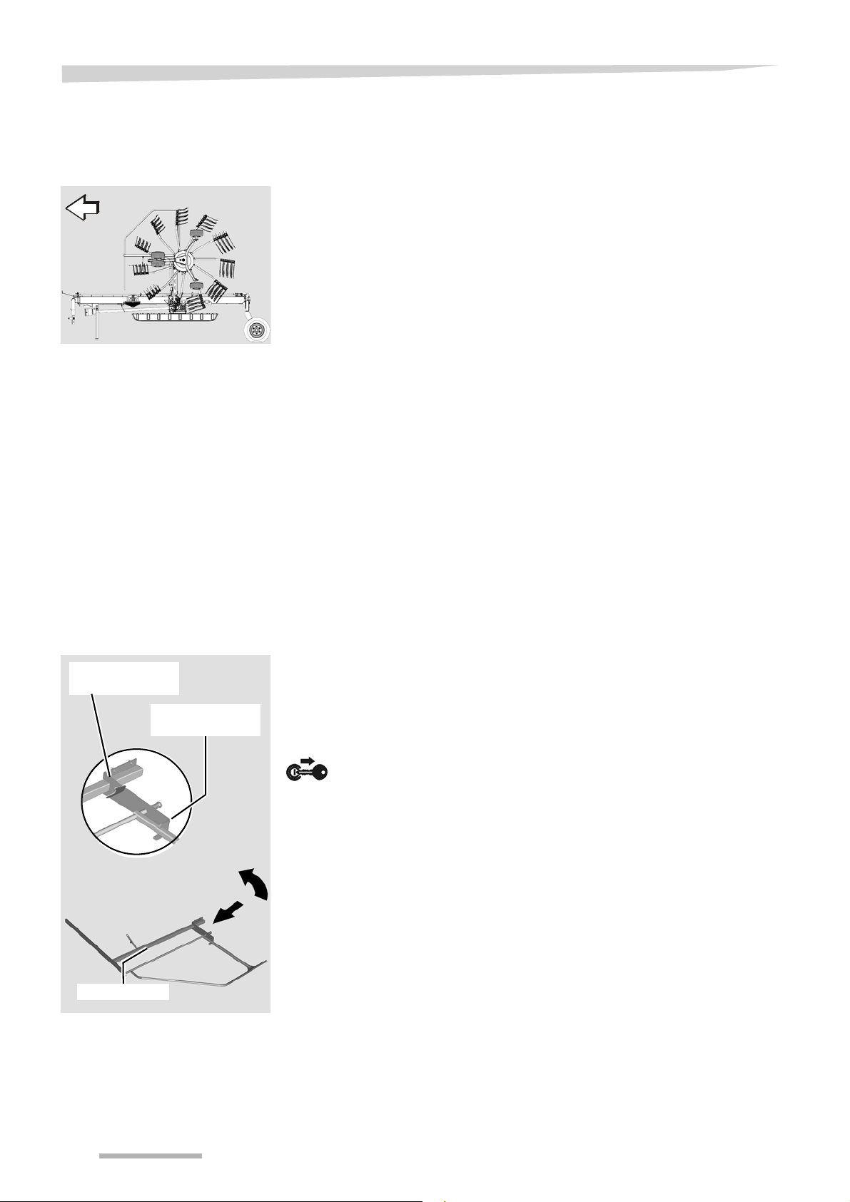
1
2
3
Latch for work
position
Latch for transport
position
Deflector bar
Prior to road transport
When driving on public roads, the machine must be in the transport
position. To prepare the machine for road transport, carry out the
following steps:
»Setting the lowest transport height«
»Folding in the deflector bar«
»Removing the tine supports«
»Place tine supports in transport holder«
»Fold the machine into the transport position«
»Checking the machine«
Move the machine onto ground that is as flat as possible before
changing from the working to the transport position.
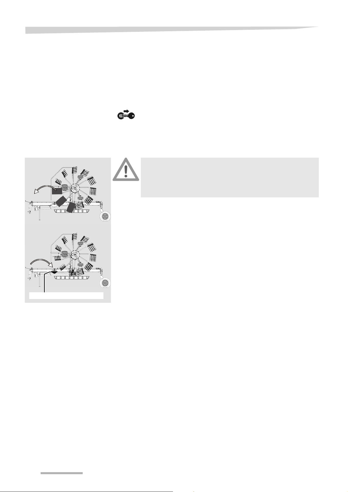
Setting the lowest
transport height
Folding in the
deflector bar
Raise the machine into the headland position using the single-
acting hydraulic control device in the tractor.
Adjust the swath to the smallest width using the double-acting
hydraulic control device in the tractor.
Before removing the tine supports, move all protective devices around
the rotors from transport to work position, and lock them in place. Fold
in the deflector bar as follows:
Lower the machine to the work position using the single-acting
hydraulic control device.
Switch off the tractor and secure it.
Release the deflector bar by pulling it out of the latch for the work
position.
Fold the deflector bar through 180° and engage it in the latch for
the transport position.
52
Page 53

Road transport
Removing the tine
supports
Remove any crops and coarse dirt.
Remove the 4 outer tine supports from both rotors, plug them into
the transport holder and secure them (see following illustration).
See »Place tine supports in transport holder«, page 54.
Switch on the tractor.
Bring the machine into the transport position.
See »Fold the machine into the transport position«, page 55.
Switch off the tractor and secure it.
Close the ball valve.
53
Page 54

Road transport
Lynch pin
Rear hole
Tine support
Transport holder
Place tine supports in
transport holder
Loosen and remove the lynch pin from the tine support.
Secure the lynch pin in the rear hole of the tine support.
Pull off the tine support.
Insert the tine support into the transport holder.
Secure the tine supports with lynch pins.
54
Page 55
Road transport
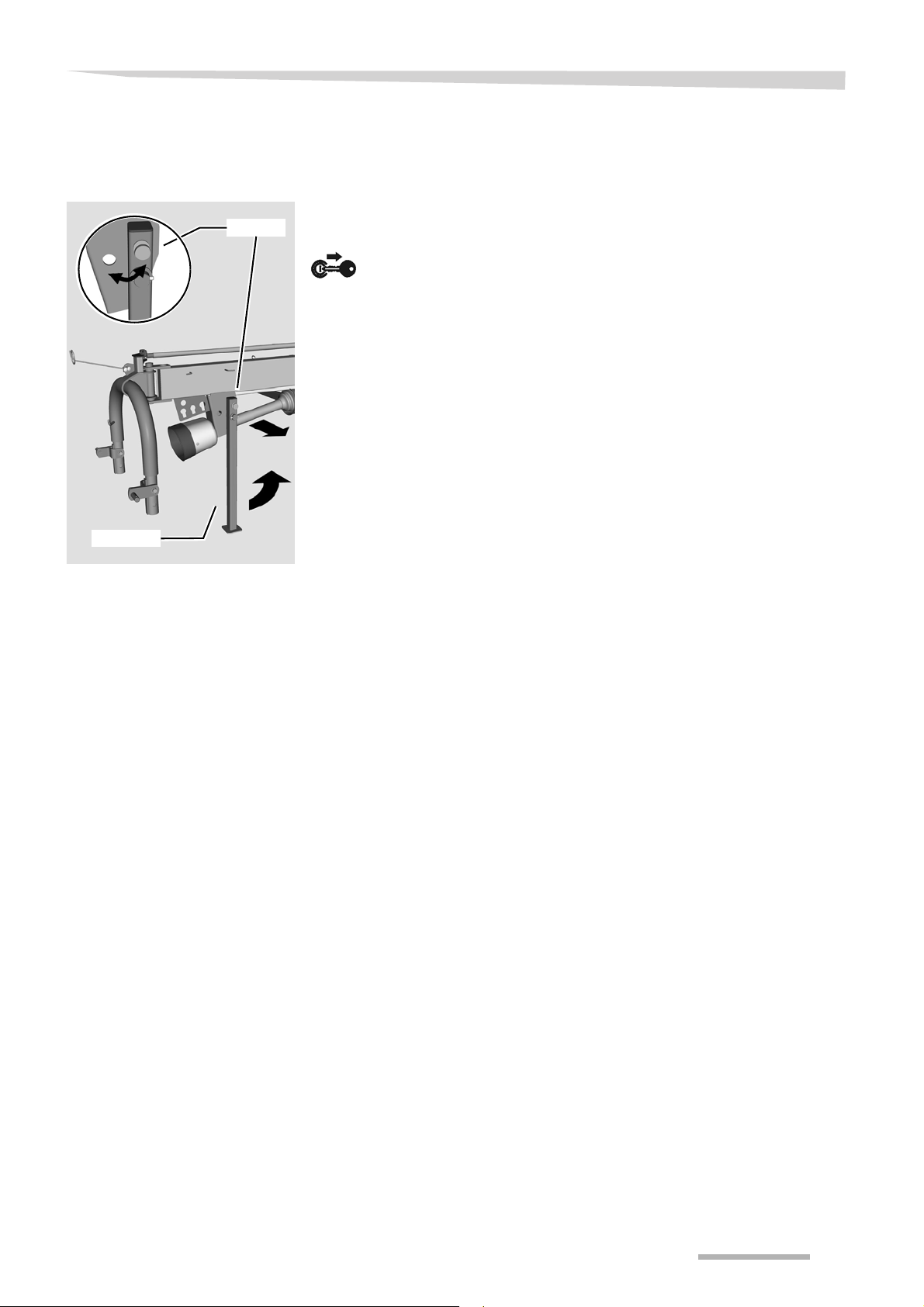
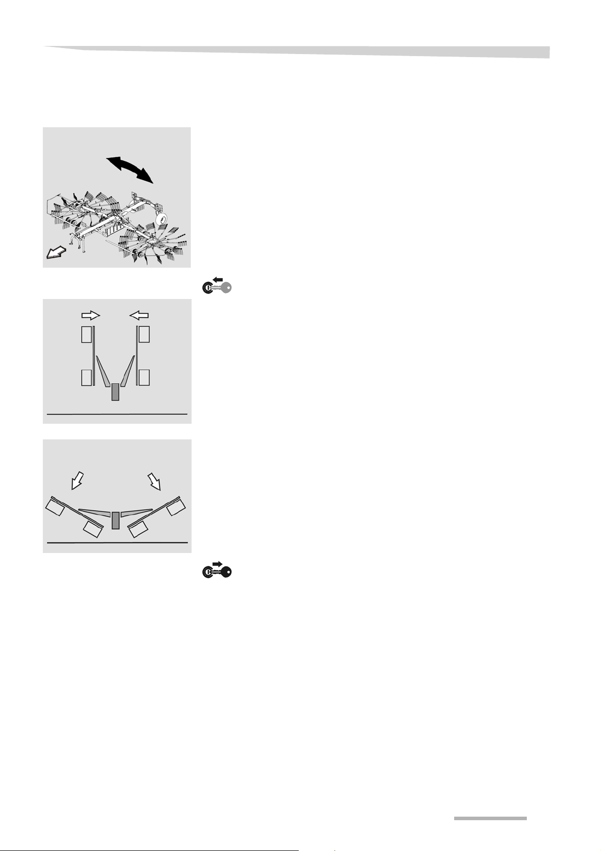
Lock
Fold the machine into
the transport
position
Make sure the machine is standing level
Before changing from the transport to the work position (and vice
versa), make sure the machine is standing level. The machine
could tip over, particularly on hillside locations. Damage to the
machine and serious or fatal injury may be caused as a result.
Observe the instructions in »Prior to road transport«, page 52.
Pull the cord on the mechanical lock and keep tensioned.
Lift the rotors into the transport position using the single-acting
hydraulic control device on the tractor.
Release the mechanical lock cord to secure the rotors.
Check that the locks of both lifting arms are engaged.
55
Page 56
Road transport
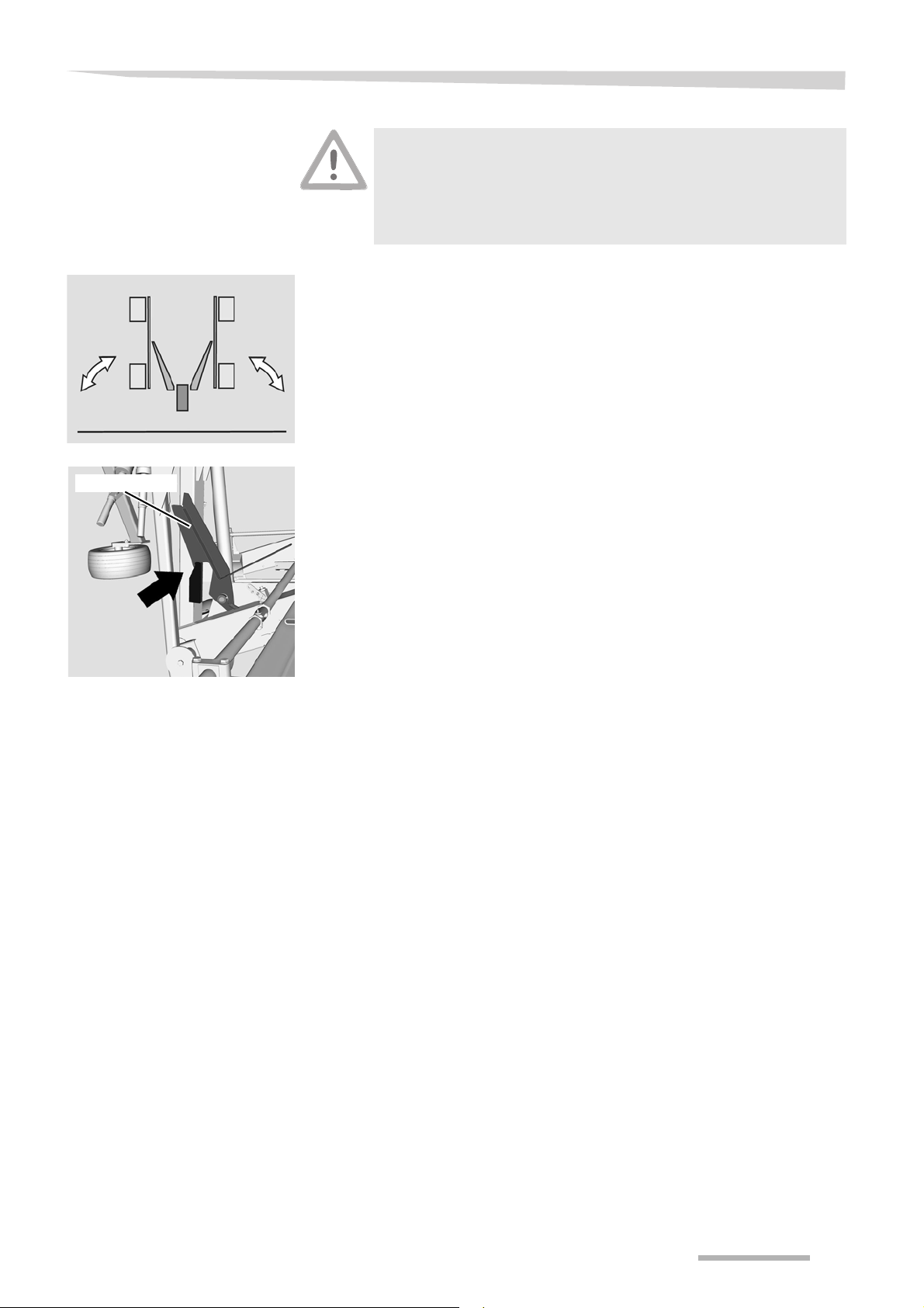
Position of the tine covers
1
2
3
Tine cover holder
1
2
3
Attaching the tine
cover
Exercise caution when close to unprotected tines
Maintain a sufficiently safe distance from exposed tines. When
working in the vicinity of the tines, ensure that you have a firm
footing (risk of slipping on wet ground). Serious or fatal injury may
be caused as a result.
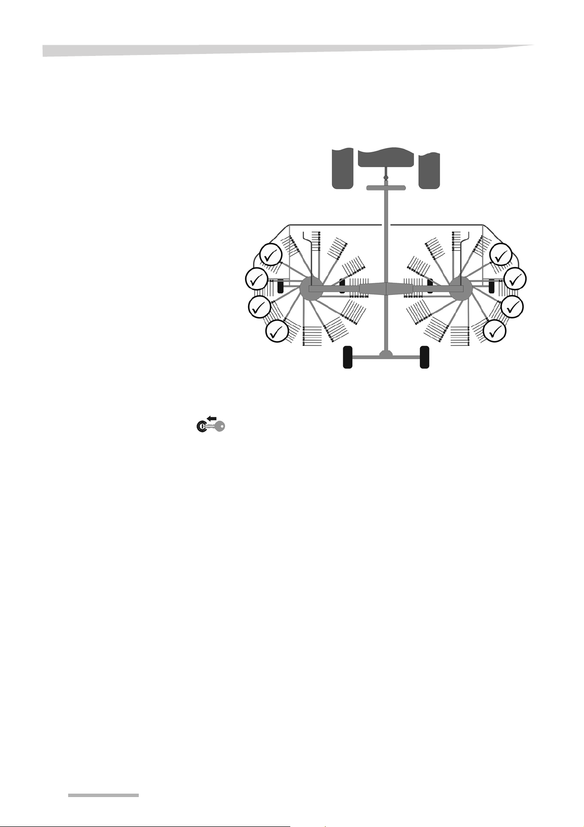
All tine supports which have tips that point at right angles to the
direction of travel and which are at a height of less than 2 metres must
be safeguarded using the tine covers provided.
On each side, three tine supports whose tines project beyond the
width of the chassis when in the transport position must be covered
(see illustration).
When in the work position, the tine covers are stowed in two holders
to the right and left of the main frame.
The tine covers are placed over the exposed tines and are attached to
the tine support via an elastic rope:
Take the first tine cover from the holder.
Place the tine cover over the tines of the upper tine support, and
attach the elastic rope hooks to the tine support.
Repeat this process for the centre and lower tine supports.
Repeat the entire process for the tine supports on the other side of
the machine.
56
Page 57

Road transport
Checking the
machine
Road transport
Prior to driving on the road, check the machine against the check list:
PTO shaft drive off?
Rotor in transport position?
Deflector bar folded?
Tine supports in transport holder and secured?
Tyre pressure correct?
Lower link secured at the sides?
Crop residue and dirt removed?
Lighting cable routed so that it is not straining and cannot get into
the tractor's wheels when cornering?
Lighting in good working order?
Follow the instructions below for road transport. There is
otherwise the risk of traffic accidents and accidents with fatal
consequences.
Before pulling away, check the immediate vicinity. Always
make sure that you have a clear field of vision and, in
particular, look out for children within the operating area of the
machine.
When the vehicle is in motion, lock the control devices on
tractor.
Do not transport people or objects on the machine.
Adjust your speed to road conditions.
Do not exceed a maximum speed of 50 km/h. Comply with the
national speed limits.
Ensure sufficient steering and braking capability. Driving char-
acteristics, steering, and braking capability are all influenced if
the machine is coupled (increased braking distance as a result
of greater inertia).
There is a danger of tipping on slopes and if corners are taken too
fast.
57
Page 58
Preparations on the field
Preparations on the fiel d
Safety
The following applies for all preparations on the field:
Observe the safety information
Observe the safety information. Disregard for safety information
can lead to serious or fatal injury. See chapter »Safety«, page 6.
Switch off the tractor and secure it
Before you dismount:
Switch off the tractor.
Remove the ignition key.
Secure the tractor against rolling away.
An unsecured tractor can run you over or trap you. Serious or fatal
injury may be caused as a result.
Avoid the hazard area
The rotors are considered a hazard area. Do not stand in the
hazard area. The rotors may lower or turn. Serious or fatal injury
may be caused as a result.
Secure the machine
Secure the machine against accidental starting and rolling away.
Use wheel chocks. The machine must stand on a level, firm and
secure surface and be supported during the work, if necessary.
Unsecured or non-supported machines can cause accidents.
Serious or fatal injury may be caused as a result.
No persons in the working area
Ensure that no persons are present in the slewing and working
area of the machine. Persons could be caught by the machine
within this area. Fatal injury may be caused as a result.
Close the ball valve
Close the ball valve before adjusting. If the ball valve is open and
there is an operating error, the machine may drop or swing out
unexpectedly. This may cause damage to the machine or
accidents with fatal consequences.
Observe the slewing process
Observe the rotors during the slewing process. If the machine
behaves unusually during the process, stop immediately to avoid
damage.
No ground contact
When the rotors are extended with the machine at a standstill, the
tines must not be in contact with the ground. Otherwise, the
machine may be damaged.
58
Page 59

Preparations on the field
General
The following work steps are described in this section:
• »Lowering the machine«
• »Fitting the tine supports«
• »Folding out deflector bar«
• »Adjusting the swath former«
59
Page 60
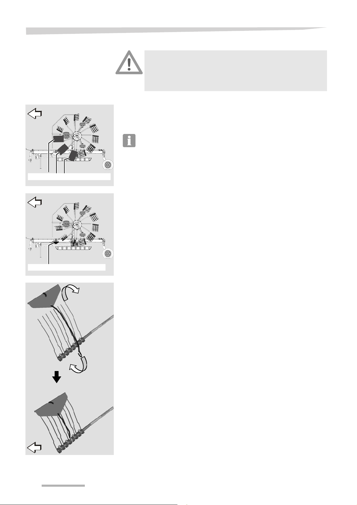
Preparations on the field
Tine cover holder
Folding the
machine into the
work position
Shutting the machine
down
Removing the tine
covers
After road transport, the machine is brought into the work position on
the field. Follow the handling instructions below:
Place the machine onto ground that is as flat as possible.
Secure the tractor against rolling away, shut off the engine and
remove the ignition key.
Firmly secure the accessories
Accessories not in use must always be stowed and secured in the
holders provided. When the machine is in motion, unsecured
accessories can come loose. Damage to the machine and serious
or fatal injury may be caused as a result.
Remove the 6 tine covers and place them in the 2 holders to the
left and right of the main frame.
Secure the tine covers in the holder. Do so by inserting the safety
splint, which is attached to the holder, through the eye bolt on the
holder.
60
Page 61
Lowering the
machine
Preparations on the field
Place the machine onto ground that is as flat as possible.
Switch on the tractor.
Use the single-acting hydraulic control device on the tractor to
release the lifting arm locking mechanism.
Pull the cord on the mechanical lock and keep tensioned.
Lower the machine into the work position using the single-acting
hydraulic control device on the tractor.
Release the mechanical lock cord.
Switch off the tractor and secure it.
61
Page 62
Preparations on the field
Remove the tine supports for both rotors from the transport holder
and fit them (see illustration).
See »Fitting the tine supports«, page 63.
Secure the tine supports with lynch pins.
Move the deflector bar to the work position until the latch engages.
See »Folding out deflector bar«, page 64.
Switch on the tractor.
Observe the instructions in chapter »Preparing for use«, section
»Working depth« on page 48.
62
Page 63

Basic settings
Lynch pin
Rear hole
Tine supports
Tine support for the left rotor
Labels
Fitting the tine
supports
Preparations on the field
Remove the tine supports from the transport holder.
Attach the tine supports to the tine supports and secure with lynch
pin.
• The tine supports for the left rotor are labelled.
• The tine supports for the right rotor are not labelled.
63
Page 64

Preparations on the field
Latch for work
position
Latch for transport
position
Deflector bar
Folding out deflector
bar
After the tine supports have been attached, all protective devices must
be moved from transport to work position.
Fold out the deflector bar as follows:
Release the deflector bar by pulling it out of the latch for the
transport position.
Fold the deflector bar through 180° and engage it in the latch for
the work position.
64
Page 65

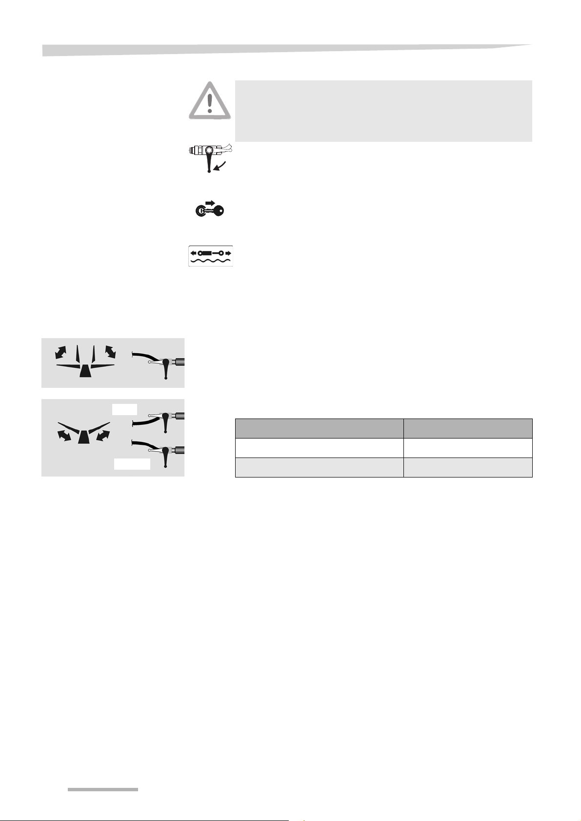
Preparations on the field
Swath former
Bolts
Swath former
Bolts
Adjusting the swath
former
Adjusting the swath
former in relation to the
direction of travel
The swath former is folded into the correct position when changing
from the transport to the work position.
It is possible to adjust the direction of travel of the swath former as
follows:
Remove the bolts.
Move the swath former into the desired position.
Fit the bolts and tighten them in the new position.
Adjusting the swath
former's height
It is possible to adjust the height of the swath former as follows:
Loosen the screws.
Adjust the height of the swath former.
Tighten the bolts in the new position.
65
Page 66

Operation
Operation
Safety
Observe the safety information
Observe the safety information. Disregard for safety information
can lead to serious or fatal injury. See chapter »Safety«, page 6.
No riding on the machine
Persons or objects must never be transported on the machine.
Carrying passengers on the machine is life threatening and
prohibited. Serious or fatal injury may be caused as a result.
No persons in the working area
Ensure that no persons are present in the slewing and working
area of the machine. Persons could be caught by the machine
within this area. Fatal injury may be caused as a result.
Maximum PTO speed 540 rpm
The PTO shaft speed must not exceed 540 rpm and must be
adapted to the condition of the crop. Higher revolution rates can
cause damage to the machine.
Only allow the PTO shaft clutch to respond for a short time
Do not allow the slip clutch to respond for longer than 3 seconds.
If the clutch responds for a longer period of time, it will become
worn and the disconnect torque will drop.
Do not compress the PTO shaft
The PTO shaft between the tractor and machine must not be
compressed when in the work or transport position. If
compressed, PTO shafts can cause damage to the machine and
tractor.
Observe the contour of the terrain
Pay even more attention when driving on an incline. Avoid inclines
on which the combination (tractor and machine) could slip or
overturn. There is an increased risk of tipping and injury in a
position at right angles to the direction of the slope.
Changes in the centre of gravity
The machine's centre of gravity changes in the single rotor work
position. Pay even more attention when driving on an incline.
Avoid inclines on which the combination (tractor and machine)
could slip or overturn. There is an increased risk of tipping and
injury in a position at right angles to the direction of the slope.
66
Page 67

Operation
General
The following work steps are described in this section:
• »Swathing«
• »Dual rotor operation«
• »Single rotor operation with pilotbox [+]«
• »Adjusting the swath width«
• »Driving on headlands«
Suitable working speeds
Select a driving speed (approx. 4-12 km/h) at which the crop is picked
up cleanly and completely. The working speed depends on the
machine settings and the particular crop.
Swath width
The swath width depends on working width, working speed, tine lift
settings and transverse rotor pitch as well as crop condition. The
swath width is between approx. 1.50 m and approx. 2.00 m.
67
Page 68

Operation
Swathing
Requirements
No persons in the working area
Ensure that no persons are present in the slewing and working
area of the machine. Persons could be caught by the machine
within this area. Fatal injury may be caused as a result.
After setting the machine as described in chapter »Preparations on
the field« page 58, you can start swathing.
The machine is set correctly as follows:
• Swath former adjusted.
• Tine supports attached and secured.
• Rotor securing implement on the rotor released.
• The single-acting hydraulic control device on the tractor is set to
the floating position.
• Machine in work position.
Start work as follows:
Switch on the tractor.
Open the ball valve.
Set the single-acting hydraulic control device on the tractor to the
floating position.
Check that there is nobody in the working area of the machine.
Switch on the PTO shaft at a low engine speed.
Slowly increase the speed.
Do not exceed the maximum speed of 540 rpm.
Select a driving speed at which the crop is picked up cleanly and
completely.
Start swathing at the edge of the field and at headlands to avoid subsequently driving over the crop.
The slip clutch of the machine may also respond at low speed if
resistance is increased due to excess crop or obstacles.
68
Page 69

Operation
Swath deposit
Dual rotor operation
Central swath with two
rotors
The following basic types of swath deposit are possible:
• »Central swath with two rotors«, page 69.
• »Single rotor operation with pilotbox [+]«, page 72.
• »Single swath with left rotor«, page 72.
• »Single swath with right rotor«, page 72.
• »Single swath with right rotor in transport position«, page 71.
• »Single swath with left rotor in transport position«, page 71.
Distance from the rotor
Maintain a safe distance from the rotor when it is rotating. Nobody
may remain in close proximity to the machine when rakes and
swathers are running. Otherwise, serious or fatal injury may be
caused as a result.
Switch on the drive for the PTO shaft at a low speed.
Select a driving speed at which the crop is picked up cleanly and
completely.
69
Page 70
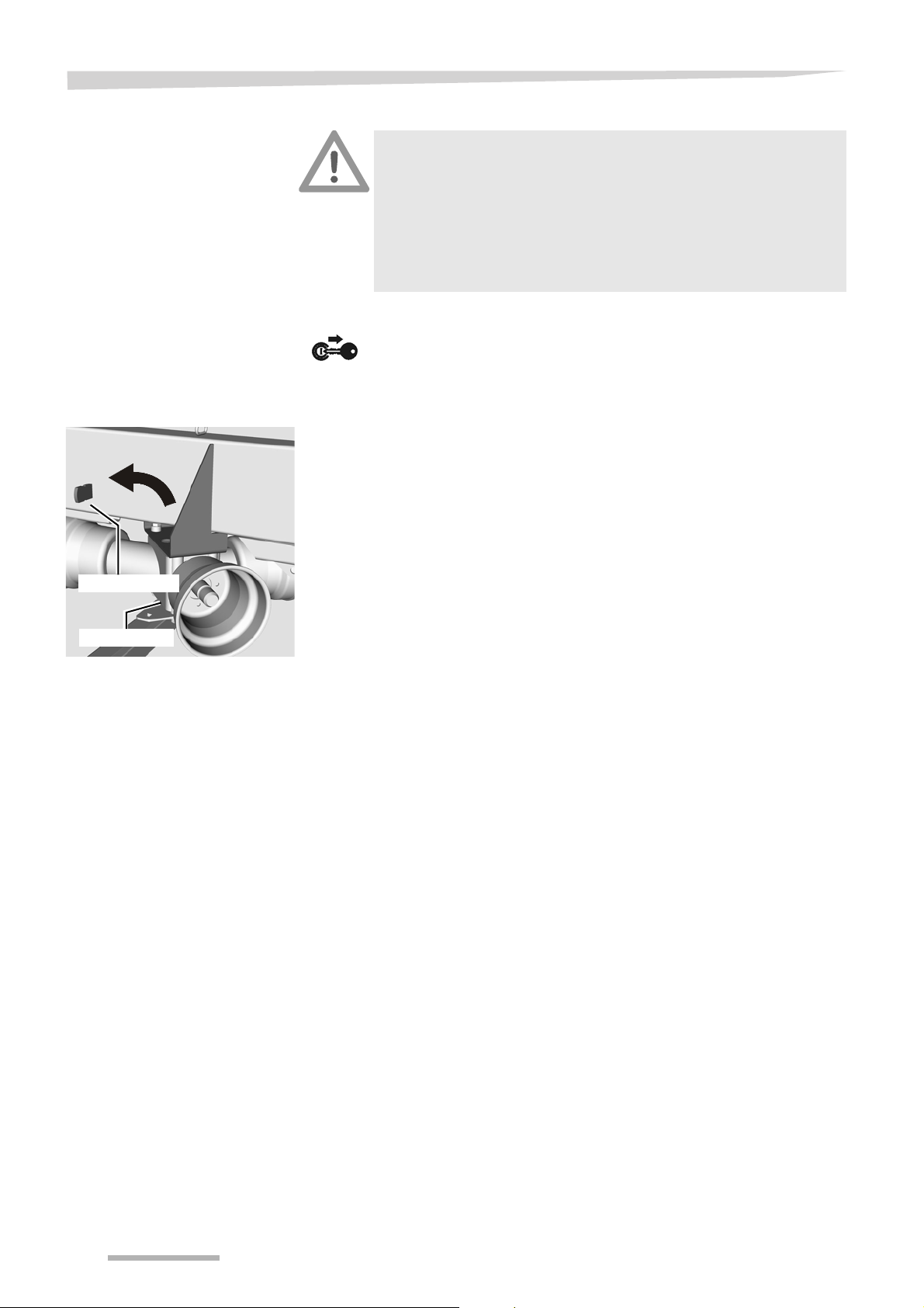
Operation
Parking stand
Angular gear
Single swath with
active rotor
Remove the side shaft
Switch off the tractor and secure it
Before you dismount:
Switch off the tractor.
Remove the ignition key.
Secure the tractor against rolling away.
An unsecured tractor can run you over or trap you. Serious or fatal
injury may be caused as a result.
The machine is in the work position for twin rotor operation.
Secure the tractor against rolling away, shut off the engine and
remove the ignition key.
Remove the side shaft from the inactive rotor:
Loosen the jubilee clip, with which the ribbed funnel is fixed to the
gear box.
Pull out the ribbed funnel.
Detach the side shaft along with the ribbed funnel.
Place the side shaft in the parking stand and secure it.
70
Page 71
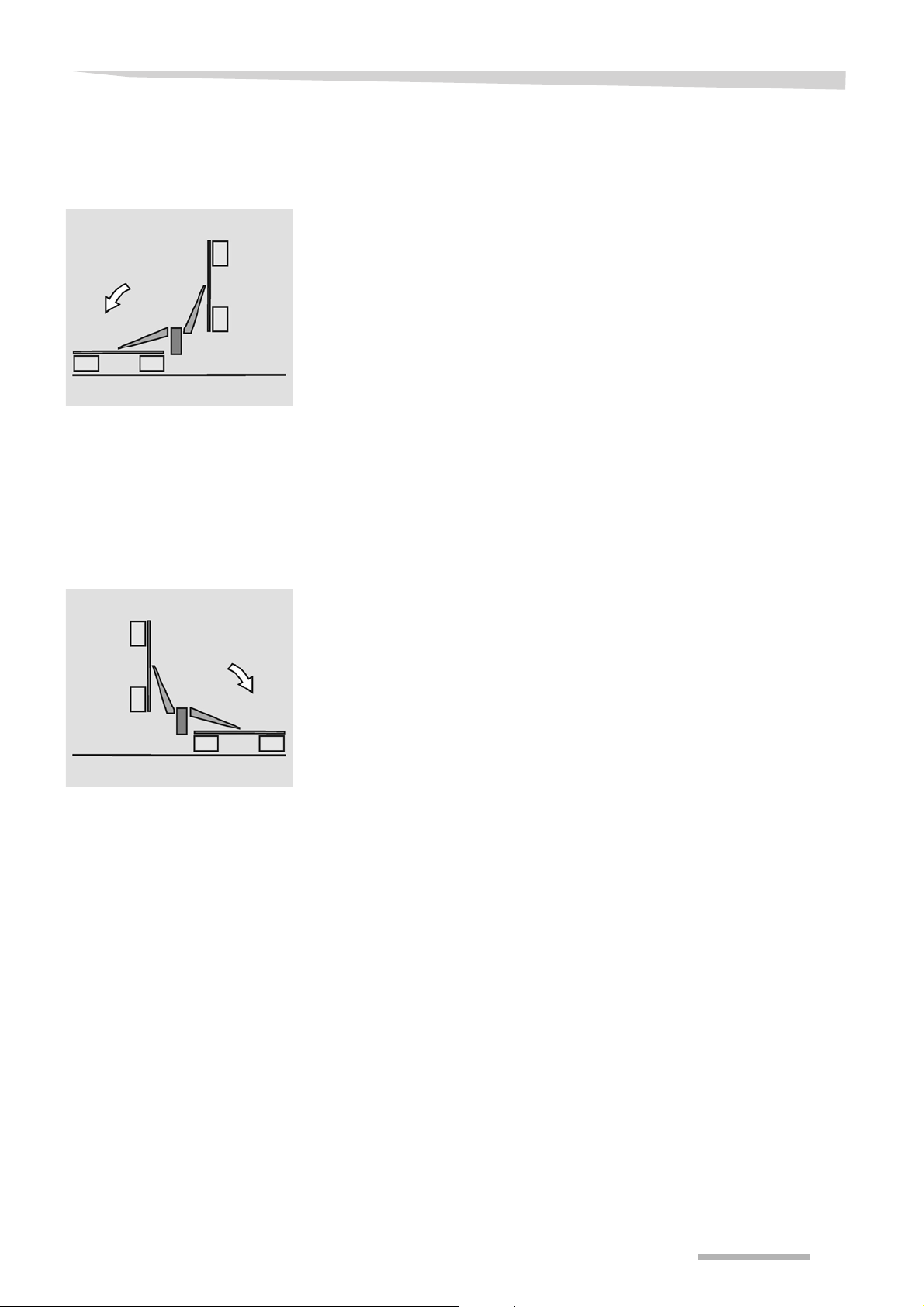
Operation
Single swath with
right rotor in transport
position
Single swath with
left rotor in transport
position
The inactive side shaft is removed.
See »Remove the side shaft«, page 70.
Using the tractor's single-acting hydraulic control unit, raise both
rotors into the transport position until the lift arms lock.
To release them, pull the cable on the mechanical locking
mechanism for the left rotor and keep tensioned.
Lower the left rotor using the tractor's single-acting hydraulic
control unit.
Switch on the drive for the PTO shaft at a low speed.
Select a driving speed at which the crop is picked up cleanly and
completely.
The left rotor picks up the crop.
The inactive side shaft is removed.
See »Remove the side shaft«, page 70.
Using the tractor's single-acting hydraulic control unit, raise both
rotors into the transport position until the lift arms lock.
To release them, pull the cable on the mechanical locking system
for the right rotor and keep tensioned.
Lower the right rotor using the tractor's single-acting hydraulic
control unit.
Switch on the drive for the PTO shaft at a low speed.
Select a driving speed at which the crop is picked up cleanly and
completely.
The right rotor picks up the crop.
71
Page 72

Operation
Single rotor
operation with
pilotbox [+]
Single swath with
left rotor
Distance from the rotor
Maintain a safe distance from the rotor when it is rotating. Nobody
may remain in close proximity to the machine when rakes and
swathers are running. Otherwise, serious or fatal injury may be
caused as a result.
The optional electro-hydraulic single lift makes it possible to deposit the
crop using either the right or left rotor.
Switch on the pilotbox and set the 3-way switch to "C".
Raise the right rotor using the tractor's single-acting hydraulic
control unit.
Switch the 3-way switch to the neutral position and switch off the
pilotbox.
Single swath with
right rotor
The left rotor picks up the crop.
Switch on the pilotbox and set the 3-way switch to "C".
Raise the left rotor using the tractor's single-acting hydraulic
control unit.
Switch the 3-way switch to the neutral position and switch off the
pilotbox.
The right rotor picks up the crop.
72
Page 73

Adjusting the swath width
Operation
By extending the rotors, the swath width can be adjusted to suit the
crop volume and the swath type using the double-acting hydraulic
control device on the tractor.
For adjustment of the swath width, the machine should be in the
headland position. Otherwise, the machine may be damaged.
Raise the machine into the headland position using the single-
acting hydraulic control device in the tractor.
Use the double-acting hydraulic control device on the tractor to
increase the pressure in order to extend the swath width.
Use the double-acting hydraulic control device on the tractor to
decrease the pressure in order to reduce the swath width.
Driving on headlands
The rotors can be raised for crossing swaths that have already been
harvested.
Raise the machine into the headland position using the single-
acting hydraulic control device in the tractor.
Lower the rotor again, in order to create new swath.
73
Page 74

Cleaning and care
Cleaning and care
Safety
The following applies to all cleaning and care work:
Observe the safety information
Observe the safety information. Disregard for safety information
can lead to serious or fatal injury. See chapter »Safety«, page 6.
Secure the machine
• Before starting cleaning operations, always switch off the
tractor's PTO shaft drive and secure it against accidental
restarting.
• Secure the machine against rolling away by using chocks.
• The machine must be standing on firm and level ground and, if
necessary, must be supported during the work.
Unsecured or non-supported machines can cause accidents.
No persons in the working area
Ensure that no persons are present in the slewing and working
area of the machine. Persons could be caught by the machine
within this area. Fatal injury may be caused as a result.
Do not clean bearings or hydraulic parts with high pressure
cleaners
Do not clean bearings or hydraulic parts with high pressure
cleaners. The high-pressure cleaner removes the grease film from
the bare metal surfaces. Metal surfaces treated in this way can
corrode. After each cleaning procedure, lubricate the bearing
points and grease uncoated parts.
Clean the bearings and hydraulic parts with care
Exercise caution when cleaning with a high-pressure cleaner.
Bearings, seals and pipe unions are not waterproof. In order to
prevent damage to the machine, the bearings, seals and pipe
unions must not be exposed to direct contact with the high
pressure water jets.
74
Page 75

Cleaning and care
Cleaning
After cleaning
Care
Lower the machine to the work position.
After each use, clean the machine of any coarse dirt and crop
residue.
Do not clean the bearings and piston rods of hydraulic cylinders
using a high-pressure cleaner.
Lubricate all bearings after cleaning.
For a long service life, we recommend the following:
Apply a protective layer of oil to all uncoated work tools. Only use
approved, biodegradable oil, e.g. rapeseed oil.
Repair any paint damage.
75
Page 76

Parking and storage
Parking and storage
Setting down the
machine in a
secure position
When setting down and parking the machine, special safety
precautions have to be observed:
Observe the safety information
Observe the safety information. Disregard for safety information
can lead to serious or fatal injury. See chapter »Safety«, page 6.
Keep children away from the machine
Forbid children from playing on or around the machine. Select a
parking area to which no unauthorised persons have direct
access. Metal edges and machine work tools can cause serious
injury.
Make sure the machine is standing level
Before changing from the transport to the work position (and vice
versa), make sure the machine is standing level. The machine
could tip over, particularly on hillside locations. Damage to the
machine and serious or fatal injury may be caused as a result.
76
Page 77
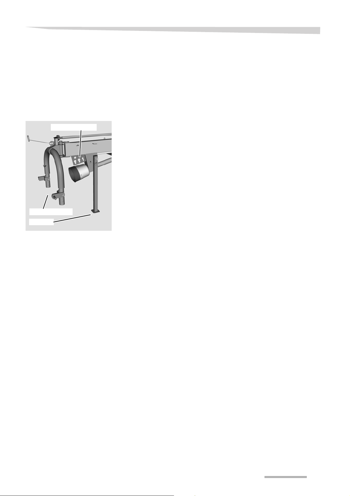
Parking and storage
Storage pockets
Attachment carrier
Sustainer
General
Uncoupling and
securing the machine
The machine must be uncoupled in the reverse order to that in which
it was coupled.
Chapter »Fold the machine into the transport position« page 55.
Chapter»Coupling the machine«, section »Coupling« page 14.
To uncouple the machine from the tractor, proceed as follows:
Bring the machine into the transport position.
Set the machine down on a firm, level surface.
Secure the tractor against rolling away, turn off the engine and
remove the ignition key.
Secure the machine against rolling away by using chocks.
Pull off the PTO shaft and place it on the holder provided.
Close the ball valve and release the hydraulic couplings.
Place hydraulic couplings in storage pockets.
Remove all tine supports which have tips that point at right angles
to the direction of travel and which are at a height of less than 2
metres.
Disconnect the lighting plug and place it in the storage pocket.
Lower the sustainer and secure with pins.
Wind the electric cables onto the hook.
Lower the lower link until the sustainer rests safely on the ground.
Release the latch between lower link and attachment carrier.
Unhitch the machine.
After the end of the season
After the end of the season and if the machine is to be stored for a long
period of time, perform the following work:
Clean the machine thoroughly.
Check all the screw joints and tighten the screws.
Repair or replace any damaged components.
Repair any paint damage.
Lubricate the machine in accordance with the lubrication schedule.
Check the tyre pressure.
Replace missing warning signs and stickers.
77
Page 78

Maintenance
Maintenance
For your safety
The following applies to all servicing work:
Observe the safety information
Observe the safety information. Disregard for safety information
can lead to serious or fatal injury. See chapter »Safety«, page 6.
Requirements for maintenance work
Only perform the maintenance operations if you have the required
expert knowledge and suitable tools. The absence of technical
knowledge or suitable tools can cause accidents and injuries.
Protect the machine against unintended starting
The following conditions must be observed for carrying out repairs
and maintenance work and rectifying malfunctions on the machine
when it is coupled:
• Switch off the tractor PTO shaft drive.
• Switch off the tractor engine.
• Remove the ignition key.
Serious accidents may be caused if the machine starts accidentally.
Use OEM replacement parts
Many components have special properties that are essential for
the stability and correct operation of the machine. Only spare parts
and accessories supplied by the manufacturer have been tested
and approved. Other products may disrupt the correct operation of
the machine and adversely affect safety. The use of non-OEM
replacement parts renders the manufacturer's guarantee null and
void and frees the manufacturer from all liability.
Secure moving parts
Moving parts must be secured with lifting gear against sliding,
folding or swivelling. Otherwise, serious injury to persons or
damage to the machine may be caused as a result.
Disconnect electrical connections before performing welding
work
Disconnect all electrical connections from the tractor when
carrying out welding on the hitched machine. Otherwise, electrical
and hydraulic systems will be damaged as a result.
78
Page 79

Maintenance
Protective measures
when handling oils or
lubricants
Additives in oils and lubricants may have adverse effects on health. As
marking in accordance with the hazardous goods regulation is not
necessary, please always ensure the following:
Avoid skin contact
Avoid skin contact with these materials. Protect your skin by
means of protective skin cream or oil-resistant gloves. Contact
can result in skin damage.
Do not use oils for cleaning
Do not use oils or lubricants to clean your hands. Swarf and
abraded material in these materials can also result in injuries.
Change contaminated clothing
Change out of clothing that is heavily contaminated with oil as
soon as possible. Oils can be hazardous to your health.
• Used oil must be collected and disposed of.
• If the skin is damaged by oil or lubricant, seek medical advice
immediately.
79
Page 80

Maintenance
Front
Left
Right
Rear
Top
Bottom
Rotary direction right
General
Direction information
This information relates to general servicing work. For all servicing
work, the machine must be locked in the work position. If the transport
position is required for maintenance work, refer to the relevant instructions for the work.
Lower the machine to the work position.
Secure the machine against rolling away by using chocks.
Direction information (right, left, front, rear) is given in relation to the
direction of travel. Rotary direction is defined as follows:
• Rotary direction right = clockwise.
• Rotary direction left = anticlockwise.
• Rotation about a vertical axis, viewed from top to bottom.
• Rotation about a horizontal axis, viewed at right angles to the
direction of travel, from left to right.
• The rotation of screws and nuts, etc. is always viewed from the
operating side.
80
Page 81

Maintenance
Maintenance terms
Task Explanation
Greasing Apply grease to the slide surfaces using a brush.
Lubrication One or two presses of the grease gun, if not specified otherwise.
Oiling
Replacement
Inspection
Observe the maintenance
intervals
Unless specified otherwise, use only plant-based oils, such as rapeseed oils.
The use of used oil will endanger your health and is also strictly prohibited.
Replace the appropriate part in accordance with the instruction in the
Maintenance chapter.
Check the tyre pressure, adjustment dimensions and seal tightness as
required, and replace any worn parts or seals.
The specifications relate to an average usage of the machine. If subjected to
heavier duty (e.g. by contracting companies), select the maintenance
intervals to be shorter. Also, for extreme working conditions (for example
heavy dust creation), shorter maintenance intervals are possible.
Listed in this table are short explanations of the most important
maintenance terms.
Maintenance
intervals
General
All screws
Visual inspection
Bearing
Hose connections
Air pressure
Lighting equipment
Hydraulics
Hydraulic hoses every 6 years
Hydraulic cylinders
Hydraulic couplings
PTO shafts
Single joints
PTO shaft guard
Profile section tube
Gearbox
Rotor gear
Angular gear
After 5 hours of operation
Once a day
After 20 hours of operation
After 30 hours of operation
After 250 hours of operation
Once per season
After heavy use
As required
In case of wear
Lubrication
Greasing
Inspection
Replacement
Cleaning
• • •
•••
• • •
••
• • •
•••
•• •
• • • •
••
•• •• •
• • • • •
•• • •
••
• •
Page
82
84
87
88
84
85
85
87
87
81
Page 82

Maintenance
Spring tines
90 Nm
20 Nm
Wheel nut M 12
20 Nm
M12 wheel nut
Bolt connections
Tightening screws
Special tightening
torques
All screws must be retightened:
• After the first 5 hours of operation.
• According to the frequency of use.
• At least once a season.
Observe the special tightening torques for the following screw connections:
• 90 Nm
spring tine.
• 270 Nm Transport chassis wheel nuts.
• 20 Nm
Rotor chassis wheel nuts.
82
Page 83

Maintenance
Tightening torques
for screwed
connections
Bolt size Bolt quality
M 6 9.9 Nm (7.3 ft.lbs) 14 Nm (10.3 ft.lbs) 17 Nm (12.5 ft.lbs)
M 8 24 Nm (17.7 ft.lbs) 34 Nm (25 ft.lbs) 41 Nm (30.3 ft.lbs)
M 10 48 Nm (35.4 ft.lbs) 68 Nm (50.2 ft.lbs) 81 Nm (59.8 ft.lbs)
M 12 85 Nm (62.7 ft.lbs) 120 Nm (88.6 ft.lbs) 145 Nm (107 ft.lbs)
M 14 135 Nm (99.6 ft.lbs) 190 Nm (140 ft.lbs) 230 Nm (166 ft.lbs)
M 16 210 Nm (155 ft.lbs) 290 Nm (214 ft.lbs) 350 Nm (258 ft.lbs)
M 20 410 Nm (302 ft.lbs) 580 Nm (428 ft.lbs) 690 Nm (509 ft.lbs)
All bolt connections must be tightened in accordance with the table
below, if no other torques are specified. On this machine, screws with
a minimum quality of “8.8” (can be seen on the screw head) are used.
The torque specifications refer to a dry coefficient of friction (0.12).
8.8 10.9 12.9
Tighten safety bolts and lock nuts to a 10 % higher value.
83
Page 84

Maintenance
Attachment carrier
and steering
2x lifting cylinder, lower side
Bearing housing
4x lifting arm bearings
Transport chassis and
steering
4x tandem axles [+]
22 x shaft end
tine support
Steering
Steering rod
2 x rotor chassis
Lubrication points for grease
Working with a
grease gun
Before applying the grease gun
clean lubricating nipples and
grease gun attachment fitting.
Lubricate the bearings with one or two presses of the grease gun. If
you feel resistance at the second press, do not press a second time.
Too much grease will force the bearings apart. Dust and dirt can
penetrate into the bearings. This leads to premature wear.
Lubricate the places listed in the illustration as follows:
• after 50 hours of operation.
• before and after the season.
• each time after cleaning with a high-pressure cleaner.
84
Page 85

Maintenance
To lubricate the PTO shaft, remove it on the coupling side and
slide the profile section tubes together.
Lubricating the PTO shafts
The manufacturer's own operating manual is included with each PTO
shaft. This includes detailed information on the relevant version of the
PTO shaft.
Check the guard components
Check all guard components of the PTO shafts for wear or
damage (visual inspection). Replace any defective guard
components. An unguarded PTO shaft or damaged guard
components can cause very serious injuries during operation.
Lubricate the single joints and their couplings as follows:
• after 50 hours of operation.
• before and after the season.
• each time after cleaning with a high-pressure cleaner.
Grease the profile section tubes:
• after 50 hours of operation.
• before and after the season.
• each time after cleaning with a high-pressure cleaner.
Lubricate the guard as follows:
• after 250 hours of operation.
• before and after the season.
• each time after cleaning with a high-pressure cleaner.
PTO shaft for rotors (side
shaft)
PTO shaft for main drive
85
Page 86
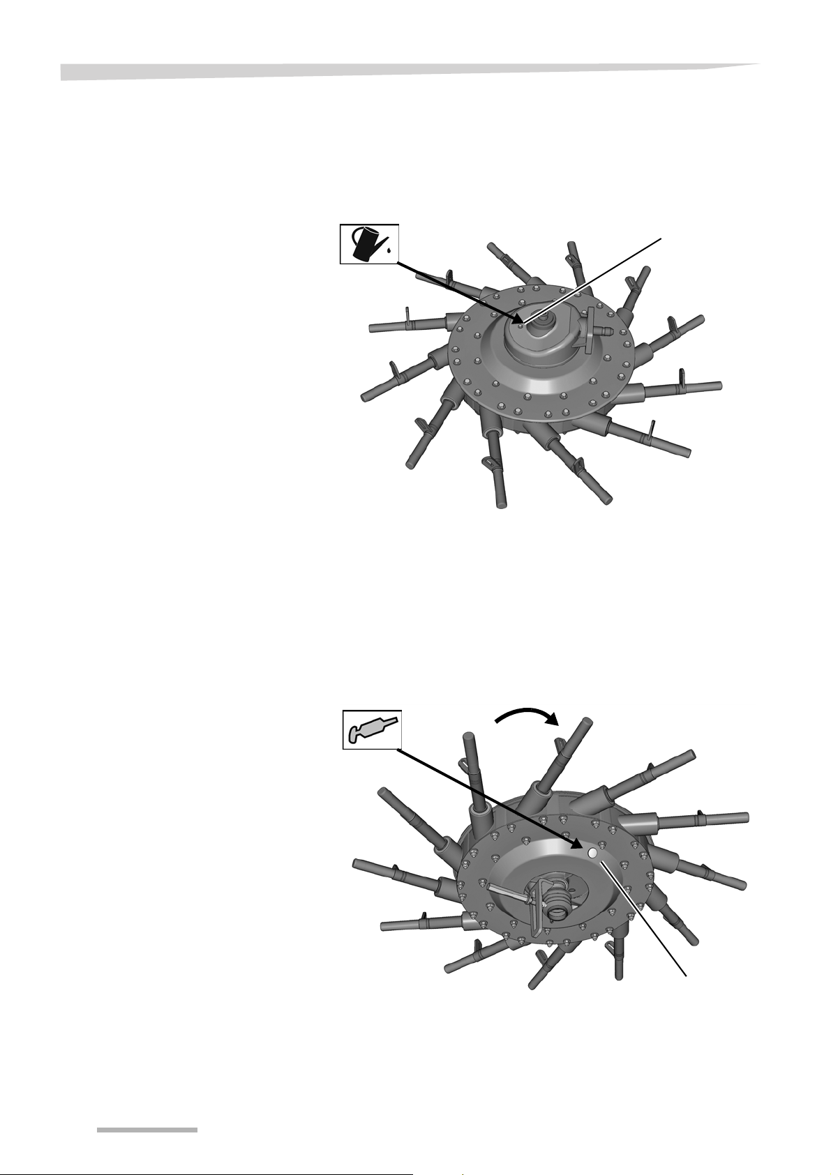
Maintenance
Bleed valve
View from above
Plug
View from below
Lubricate rotors
Check the oil level with the machine horizontal only if there is visible
loss of oil.
Check the oil level at both rotor gears using the bleed valve.
If there is a visible loss of oil, top up to the required volume.
Remove all tine supports and the plug under the rotor.
Turn rotor by hand so that the filling port is between two tine arms.
Once per season, fill between the cam track with 2-3 pumps on the
Move the rotor further and repeat the process until the cam track is
Refit plug and tine supports.
grease gun.
fully lubricated.
86
Page 87

Maintenance
Filling/drain screw
Angular gear
Filling quantities
Tyres
Tyre pressure
Check the oil level with the machine horizontal only if there is visible
loss of oil.
Gearbox Max. oil capacity [litres]
SAE 90 API-GL-4
Angular gear box (Y-transmission) 0.9
Rotor gear, left 0.6
Rotor gear, right 0.6
Do not drive with worn or damaged tyres
Replace worn or damaged tyres immediately. There is a high risk
of accident when driving on the road with such tyres.
Check the tyre pressure on a regular basis:
• once a day.
• before any road transport
• as required (for example before setting the tine height).
• before and after the season.
Tyre pressure [bar]
Rotor chassis 1.5
Transport chassis 2.5
87
Page 88

Maintenance
Hydraulics
Hydraulic hoses
Hydraulic system at zero pressure
Work must only be performed on the hydraulic system if the tractor
and machine hydraulic system is at zero pressure. A pressurised
hydraulic system can trigger unforeseen movements on the
machine and can cause serious machine damage and personal
injury. Serious or fatal injury may be caused as a result.
Exercise caution when welding
Do not perform any welding work in the vicinity of the hydraulic
hoses. Hydraulic oil can catch fire very easily.
Clean hydraulic system
Close or disconnect the quick couplings with great care. Remove
any dirt or air which has entered the hydraulic system. The
hydraulic system may otherwise be seriously damaged. Material
damage or personal injury may be caused as a result.
Collect escaping oil
Escaping oil must be collected and disposed of in accordance with
national regulations. Otherwise, damage may be caused to the
environment.
Replace hydraulic hoses every six years
Hydraulic hoses age without showing externally visible signs.
Replace hydraulic hoses every six years. Defective hydraulic lines
can cause serious or fatal injuries.
Lower the machine to the work position.
Depressurise the system.
Switch off the tractor.
Remove the ignition key.
Disconnect the hydraulic hoses.
Replace hydraulic hoses.
88
Page 89

Checking sliding
Sliding elements
Telescopic arm
Lifting arm
Lock nut
Lifting arm
Telescopic arm
Align the telescopic arm
with a small degree of
play in the lift arm.
elements
Maintenance
The sliding elements on the two lifting arms ensure smooth and even
running of the telescopic arms. The sliding elements must be checked
on a regular basis, and readjusted and the sliding surfaces lubricated
if necessary.
Check that the telescopic arms retract and extend correctly in the
headland position. Readjust the sliding elements in the case of:
• Uneven or jerky movements of the lift arms in the headland
position.
• Inclined position of the telescopic arm in the lift arm.
• Large vibrations of the rotor in the headland position.
Adjusting the sliding
elements
Fold the machine into its work position.
Undo the lock nut.
Adjust the sliding element by means of bolts so that the telescopic
arm moves in and out evenly and freely in the headland position.
Tighten the lock nut.
Using a brush, apply grease to the sliding surfaces of the
telescopic arms.
When readjusting the sliding elements, make sure that you first tighten
the screws until they lock (max 20 Nm), then slacken them slightly
(approx. 1/2 turn).
• If the sliding elements are fastened too tightly, the telescopic arms
will not travel smoothly.
• If the sliding elements are not fastened sufficiently, the rotor will
vibrate.
In both cases, this may result in damage to the machine.
89
Page 90
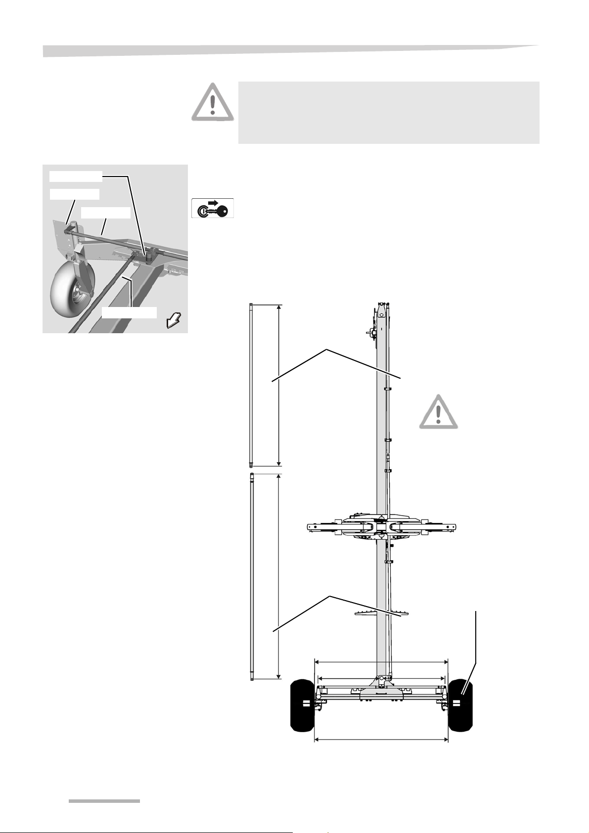
Maintenance
Track arm
Steering arm
Track rod
Steering rod
Front
steering rod
L1 = 2,464 mm
A
A + 3 mm
S
S
Rear
steering rod
L2 = 2,612 mm
Track rod S = 1,015 mm
Only rear
steering rod is
adjustable.
Checking the track
Never carry out work on the steering
Contact your dealer if specifications differ. Never carry out any
work on the steering or tracking yourself. There is otherwise the
risk of traffic accidents and accidents with fatal consequences.
If the machine rolls at an offset angle to the tractor when driving a
straight line, the directional stability is set incorrectly. Proceed as
follows:
Switch off the tractor and secure it.
Control length of the front steering rod: L1 = approx. 2464 mm.
Control length of the rear steering rod: L2 = approx. 2612 mm.
Control length of the track rods: S = 1015 mm
Check track A at the front and rear sides of the tyres.
•Front: A
•Rear: A + 3 mm
90
Page 91

Additional equipment
Tine saver
Tine leg
Direction of rotation of the rotor
Pilotbox
Tandem axle
Additional equipment
Additional
equipment
Tine saver [+]
The following additional equipment is available for this machine. All
items of additional equipment are original parts, and are available from
your dealer.
Additional equipment which is not part of the standard scope of delivery
is indicated by a plus symbol [+] in this manual.
If the tines are broken, the tine saver can prevent the broken-off part
from being lost. Any following machines, for example straw cutters,
are then not damaged by lost tines in the crop. Observe the separate
assembly instructions.
For a good swath deposit, both tine legs must run parallel to one another after the tine savers have been fitted.
Fit one tine saver on each tine.
Visually check that both tine legs run parallel to each other..
Electro-hydraulic
single lift +]
The optional electro-hydraulic single lift makes it possible to deposit the
crop using either the right or left rotor.
Tandem axles [+]
The optional tandem axles make for better contours. Note: the wide
track is in front.
The tandem axles replace the rear running wheels. Separate
assembly instructions are supplied.
91
Page 92

Additional equipment
Rubber buffer
Spare wheel
Autan-Buffer
The optional Autan-buffer provides better contour guidance and
reduces the load on the lift arms.
Spare wheel
The optional spare wheel is fitted to the deflector bar of the machine.
The spare wheel can be fitted to the machine's deflector bar. Separate
assembly instructions are supplied.
92
Page 93

Eliminating faults
Eliminating faults
Faults
Problem Cause Solution
Rotor is leaving crop in situ on one side
and is digging too deeply into the
ground on the other side.
Rotor is leaving crop in situ across the
entire width.
Faults can often be eliminated quickly and easily. Before contacting
Customer Service, refer to the table to check whether you can remedy
the fault yourself.
In case of a fault, proceed as follows:
Immediately stop operation.
Switch off the tractor PTO shaft drive.
Secure the tractor against rolling away, shut off the engine and
remove the ignition key.
The fault must be repaired before work can be resumed.
.
Do not operate in the event of a fault
The fault must be repaired before work can be resumed. Otherwise,
damage to the machine and serious or fatal injury may be caused
as a result.
Chapter »Preparing for use«, section
Incorrect adjustment of rotor pitch.
Working depth set too high.
»Rotor pitch«, page 45
Chapter »Preparing for use«, section
»Rotor pitch«, page 45
Crop is heavily contaminated. Rotor tines set too low.
Rotor tines set too high.
Machine not operating cleanly at high
speed.
Rotor dragging crop along –
Unclean swath form
PTO shaft coupling responding
frequently.
Noise production during work
Machine rolls offset behind the tractor
when driving in a straight line.
Rotor not working cleanly.
Uneven terrain.
Speed too high to process crop
mass
Crop mass too large. Reduce speed.
Rotary speed too high. Reduce speed.
Crop mass too large or uneven. Reduce speed.
Rotor tines set too low.
Loose screwed connections or
worn-out tine supports.
Tine support bent
Steering/tracking incorrectly
adjusted or worn out.
Poor adaptation to the contours of
the land due to severe rotor load
reduction.
Chapter »Preparing for use«, section
»Rotor pitch«, page 45
Chapter »Coupling the machine«, section
»Coupling the lower link«, page 36
Chapter »Preparing for use«, section
»Rotor pitch«, page 45
Reduce speed.
Chapter »Preparing for use«, section
»Rotor pitch«, page 45
Check tine supports and screwed
connections on tines.
Contact dealer.
Please consult your dealer. You will find
assistance under »Circuit diagrams«, page
94.
Telescopic arms not running smoothly.
Attach tine supports to the frame in the
headland position.
Sliding elements wrongly adjusted.
Not enough play set.
Sliding elements wrongly adjusted.
Too much play set.
Adjust sliding elements correctly. See
»Checking sliding elements«, page 89.
Adjust sliding elements correctly. See
»Checking sliding elements«, page 89.
93
Page 94

Circuit diagrams
Left lift arm
Tractor hydraulics
Lift arm extension
Electro-hydraulic single lift
Restrictor
0.5 mm
Right lift arm Swath former
Restrictor
1.5 mm
Restrictor
1.5 mm,
Y1
Y3
Circuit diagrams
Hydraulic circuit diagram
94
Page 95

Lighting circuit
1/L 2/54g 3/31 4/R 5/58R 6/54 7/58L
Yellow
White
Green
Brown
Red
Black
Right indicator
Right brake light
Right rear light
Right side light
Yellow
White
Red
Brown
Black
White
Left side light
White
Black
Black
Connector and socket
7-pin in accordance with ISO 1724
Left rear light
Left indicator
Left brake light
Earth
Connecting plug
7-pin in accordance with ISO 1724
diagram
Circuit diagrams
95
Page 96

Decommissioning
Decommissioning
Environment
During decommissioning, the individual parts must be disposed of
properly and in an environmentally friendly manner. Please observe
the waste disposal guidelines that are currently in force.
Plastic parts
Plastic parts can be disposed of in normal household waste (residual
waste), depending on the laws specific to your country.
Metal parts
All metal parts can be sent for recycling.
Oil
In terms of waste legislation, environmentally-compatible hydraulic
oils must be stored, collected and disposed of separately in
accordance regulations.
Rubber
Rubber parts, such as hoses or tyres, must be brought to a rubber
recycling centre.
96
Page 97

EC Conformity Declaration
Type plate and CE marking
EC Conformity Declaration
Conforms to
EC Directive
2006/42/EC
We
Kverneland Group Kerteminde AS
Taarupstrandvej 25
DK-5300 Kerteminde
Denmark
declare with sole responsibility that the product
SwatMaster 8442
Andex 844
9584 C
and its accessories
Model: VF6588
Valid from machine number:
VF65882401
to which this declaration relates, comply with the relevant basic health
and safety requirements of EC Directive
2006/42/EC.
To demonstrate our compliance with the health and safety requirements quoted in the EC Directive, we make reference to the following
standards:
• DIN EN ISO 12 100:2010
• DIN EN ISO 4254-1:2009 + AC:2010
• DIN EN ISO 4254-10:2009 + AC:2010
• DIN 11001-3:1998
Kverneland Group Kerteminde AS
Kerteminde, 27.08.2012
Uwe Kellermeier
EC authorised representative
97
Page 98

EC Conformity Declaration
98
Page 99

Index
Index
A
Adjusting
Chassis
Rotor pitch
Single-pass swath
Swath former
Working depth
45
45
69
73
45
C
Cam disk 47
Care
75
Check list
Headlands
Road transport
Work position
Circuit diagram
Hydraulics
Lighting equipment
Cleaning
Component designations
Conformity Declaration
Connection
Electrical
Hydraulic couplings
Control cam
Coupling
PTO shaft
73
57
61
94
95
75
23
97
40
42
47
38
D
Deflector bar
Folding out
Direction information
Disposal
Metal parts
Plastic parts
Dual rotor operation
64
80
96
96
69
L
Lifting the tines 47
Lower link
Coupling
Lubrication points
General
PTO shafts
36
84
84
85
M
Machine
Putting away after the season
Setting down
Uncoupling
Maintenance
Bolt connections
Lubrication points
Maintenance intervals
76
77
78
82
84
81
77
O
Oil
disposal of
Filling quantities
Protective measures
Operation
79
87
79
66
P
Preparation
Transport position
Work position
Preparations on the field
Proper use
PTO shaft
Adapting the length
Attaching
Lubrication
22
38
85
52
59
58
87
E
EC Conformity Declaration 97
Explanation
Maintenance terms
81
F
Filling quantities 87
Fitting the tine supports
63
H
Hydraulic single lift
Adjusting
73
R
Range of application 22
Road transport
50
S
Safety 6
Care and maintenance
Hitching
Operation
Pictorial symbols
Road transport
Unhitching
Scope of delivery
10, 14
18
19
16
20
8
99
Page 100

Index
Checking 31
Single-pass swath
Speed
57
Swath deposit
Dual rotor operation
Swath former
Adjusting the direction of travel
Adjusting the height
Swath width
Adjusting
T
Target group 4
Technical specifications
Dimensions in transport position
Dimensions in work position
Implement equipment
Machine equipment
Tractor equipment
Weights
Tightening torques
Bolt connections
Spring tines
Twin rotor swather
Tyres
87
Tyre pressure
69
69
69
65
65
73
24
25
27
27
26
26
83
82
22
87
W
Wheel chocks 39
100
 Loading...