

Kubota M105S Workshop Manual

WORKSHOP MANUAL
KiSC issued 03, 2007 A
TRACTOR
M105S

TO THE READER
KiSC issued 03, 2007 A
This Workshop Manual has been prepared to provide servicing personnel with
information on the mechanism, servi ce and maintenance of M105S. It is divi ded into
three parts, “General", “Mechanism” and “Servicing”.
■ General
Information on the tractor identification, the general precautions, maintenance check
list, check and maintenance and special tools are described.
■ Mechanism
Information on the construction and function are included. This part should be
understood before proceeding with troubleshooting, disassembling and servicing.
Refer to Diesel Engine / T ractor Mechanism Wor kshop Manual (Code No. 978 9701872 / 97897-18200) for the one which has not been described to this workshop
manual.
■ Servicing
Information on the troubleshooting, servicing specification lists, tightening torque,
checking and adjusting, disassembling and assembling, and servicing which cover
procedures, precautions, factory specifications and allowable limits.
All information illustrations and specifications contained in this manual are based on
the latest product information available at the time of publication.
The right is reserved to make changes in all information at any time without notice.
Due to covering many models of this manual, information or picture being used have
not been specified as one model.
December 2004
© KUBOTA Corporation 2004
M105S, WSM
SAFETY FIRST
KiSC issued 03, 2007 A
SAFETY INSTRUCTIONS
SAFETY INSTRUCTIONS
This symbol, the industry’s “Safety Alert Symbol”, is used throughout this manual and on labels on
the machine itself to warn of the possibility of personal injury. Read these instructions carefully.
It is essential that you read the instructions and safety regulations before you attempt to repair or use
this unit.
DANGER : Indicates an imminently hazardous situation which, if not avoided, will result in
death or serious injury.
WARNING : Indicates a potentially hazardous situation which, if not avoided, could result in
death or serious injury.
CAUTION : Indicates a potentially hazardous situation which, if not avoided, may result in
minor or moderate injury.
■ IMPORTANT : Indicates that equipment or property damage could result if instructions are not
followed.
■ NOTE : Gives helpful information.
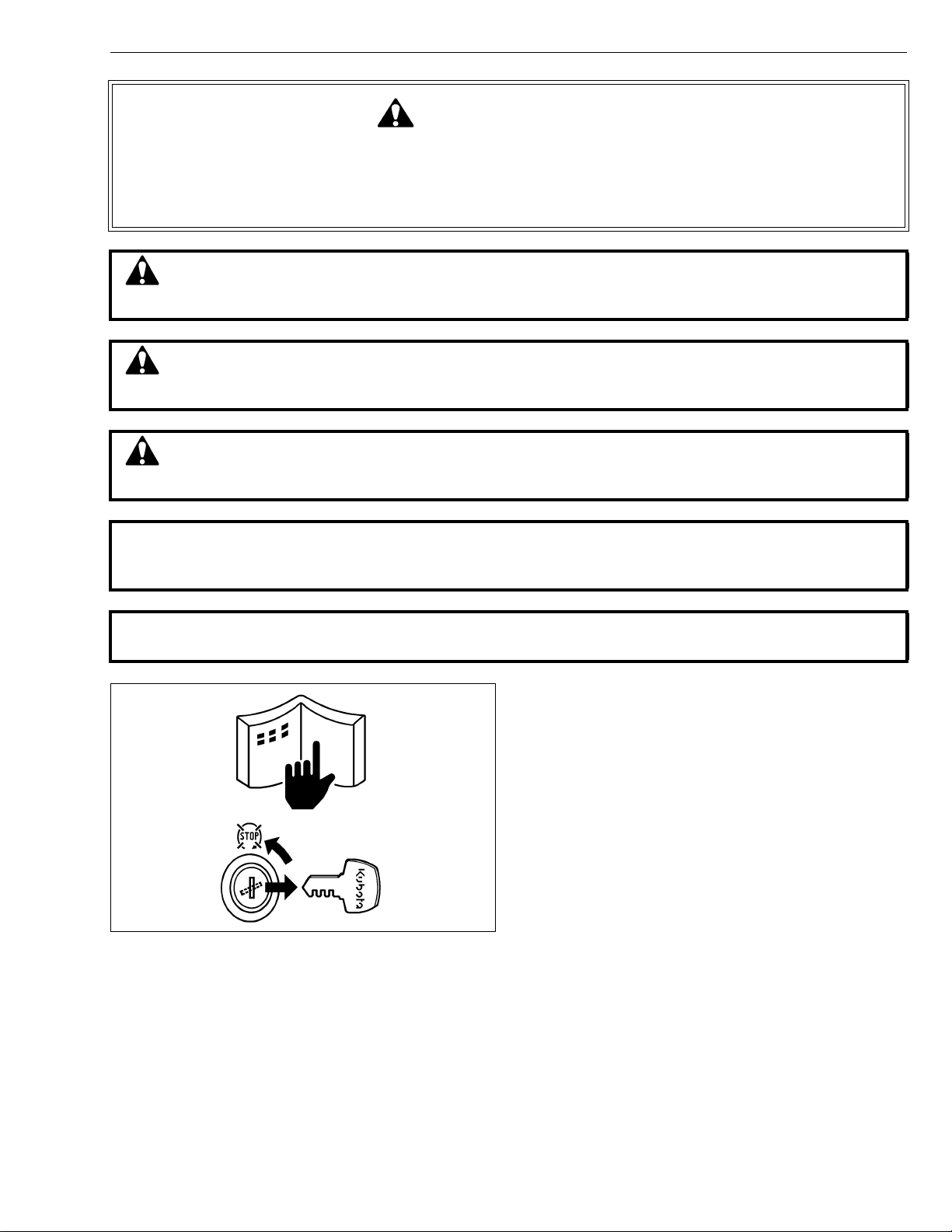
BEFORE SERVICING AND REPAIRING
• Read all instructions and safety instructions in this
manual and on your machine safety decals.
• Clean the work area and machine.
• Park the machine on a firm and level ground, and set
the parking brake.
• Lower the implement to the ground.
• Stop the engine, and remove the key.
• Disconnect the battery negative cable.
• Hang a “DO NOT OPERATE” tag in operator
station.
1
M105S, WSM
KiSC issued 03, 2007 A
SAFETY INSTRUCTIONS
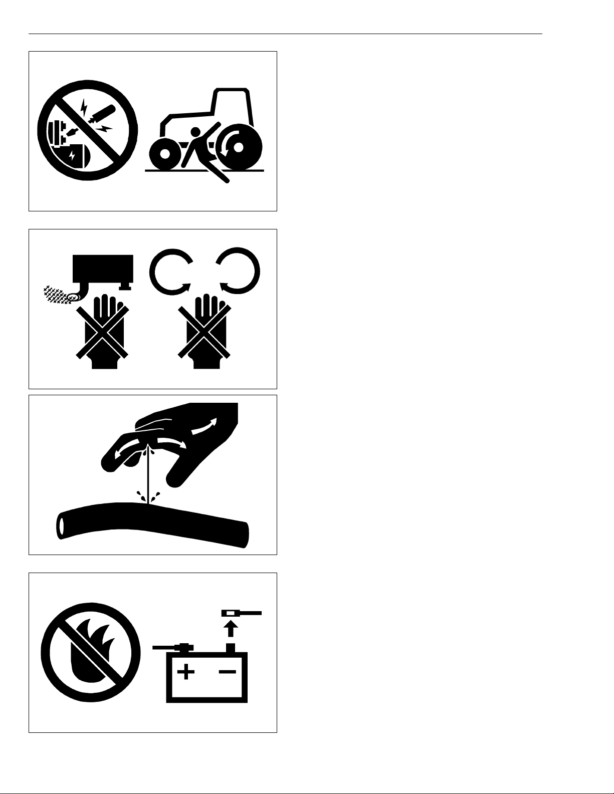
SAFETY STARTING
• Do not start the engine by shorting across starter
terminals or bypassing the safety start switch.
• Do not alter or remove any part of machine safety
system.
• Before starting the engine, make sure that all shift
levers are in neutral positions or in disengaged
positions.
• Never start the engine while standing on ground.
Start the engine only from operator’s seat.
SAFETY WORKING
• Do not work on the machine while under the influence
of alcohol, medication , or other substances or while
fatigued.
• Wear close fitting clothing and safety equipment
appropriate to the job.
• Use tools appropriate to the work. Makeshift tools,
parts, and procedures are not recommended.
• When servicing is performed together by two or more
persons, take care to perform all work safely.
• Do not work under the machine that is supported
solely by a jack. Always support the machine by
safety stands.
• Do not touch the rotating or hot parts while the engine
is running.
• Never remove the radiator cap while the engine is
running, or immediately after stopping. Otherwise, hot
water will spout out from radiator. Only remove
radiator cap when cool enough to touch with bare
hands. Slowly loosen the cap to first stop to relieve
pressure before removing completely.
• Escaping fluid (fuel or hydraulic oil) un der pressure
can penetrate the skin causing serious injury. Relieve
pressure before disconnecting hydraulic or fuel lines.
Tighten all connections before applying pressure.
AVOID FIRES
• Fuel is extremely flammable and explosive under
certain conditions. Do not smoke or allow flames or
sparks in your working area.
• To avoid sparks from an accidental short circuit,
always disconnect the battery negative cable first and
connect it last.
• Battery gas can explode. Keep sparks and open
flame away from the top of b attery, especially when
charging the battery.
• Make sure that no fuel has been spilled on the engine.
2
M105S, WSM
KiSC issued 03, 2007 A
SAFETY INSTRUCTIONS
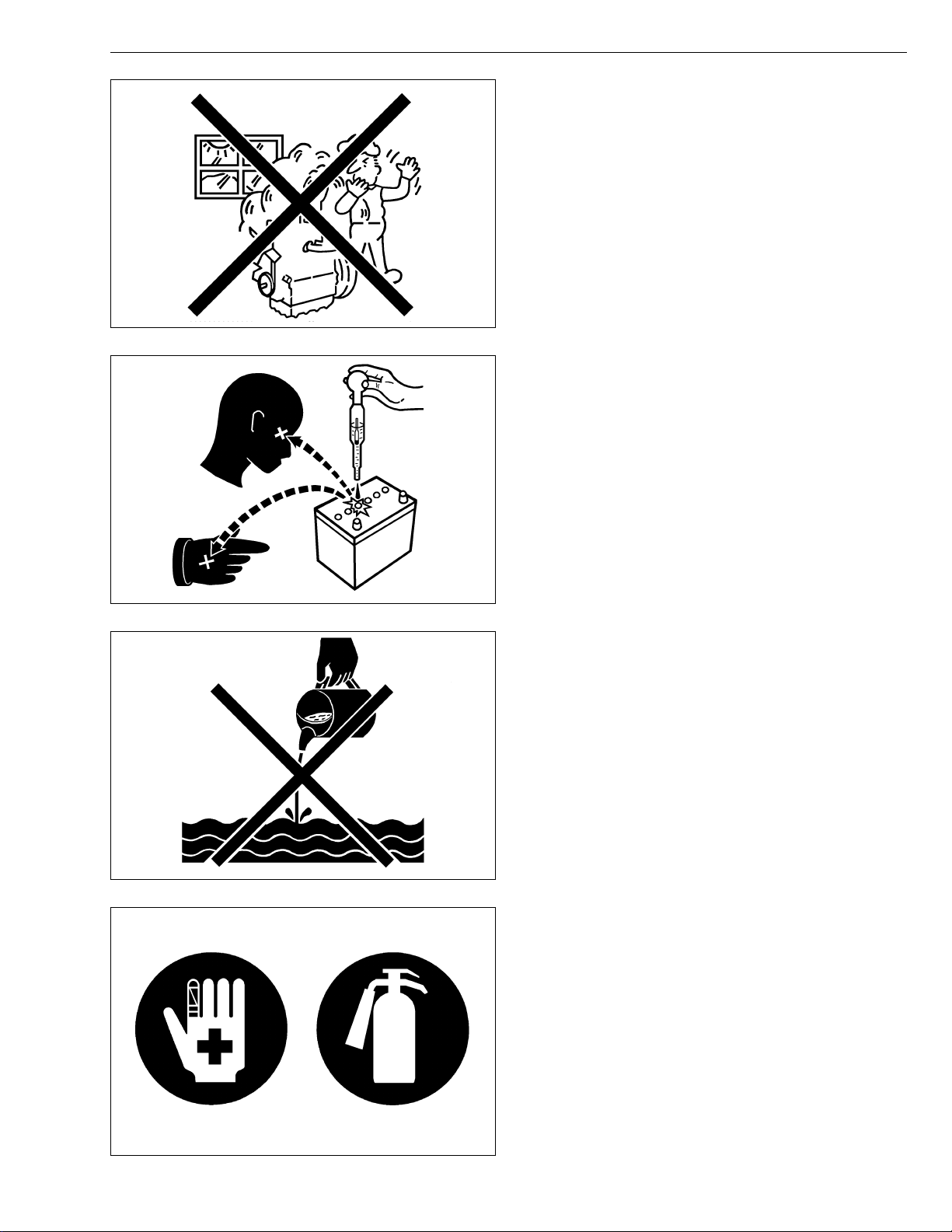
VENTILATE WORK AREA
• If the engine must be running to do some work, make
sure the area is well ventilated . Neve r run the eng ine
in a closed area. The exhaust gas contains poisonous
carbon monoxide.
PREVENT ACID BURNS
• Sulfuric acid in batte ry electrolyte is poisonou s. It is
strong enough to burn skin, clothing and cause
blindness if splashed into eyes. Keep electrolyte
away from eyes, hands and clothing. If you spill
electrolyte on yourself, flush with water, and get
medical attention immediately.
DISPOSE OF FLUIDS PROPERLY
• Do not pour fluids into the ground, down a drain, or
into a stream, pond, or lake. Observe relevant
environmental prot ectio n regulati ons whe n disp osing
of oil, fuel, coolant, electrolyte and other harmful
waste.
PREPARE FOR EMERGENCIES
• Keep a first aid kit and fire extingui sher handy at all
times.
• Keep emergency numbers for doctors, ambulance
service, hospital and fire department near your
telephone.
3
M105S, WSM
KiSC issued 03, 2007 A
SAFETY INSTRUCTIONS
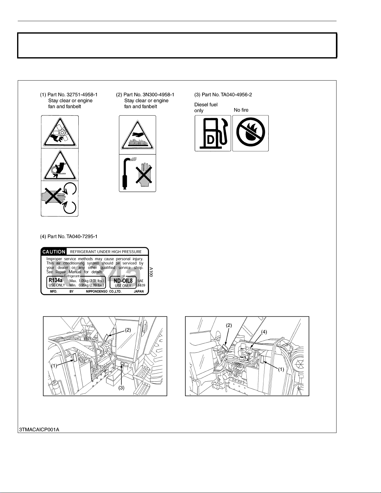
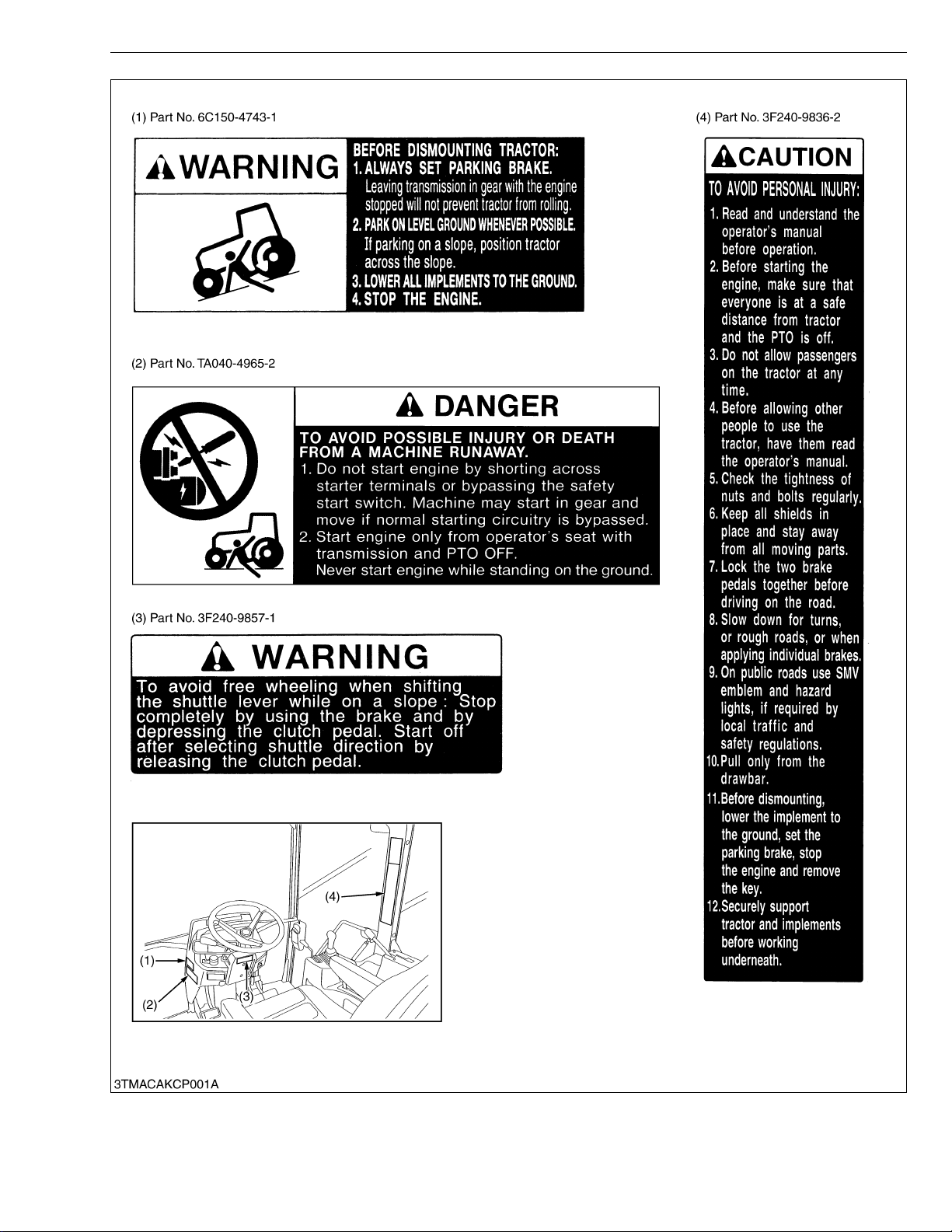
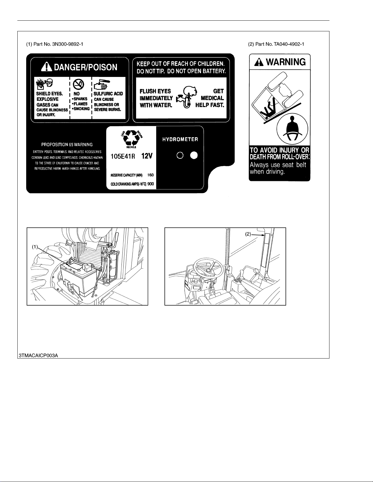
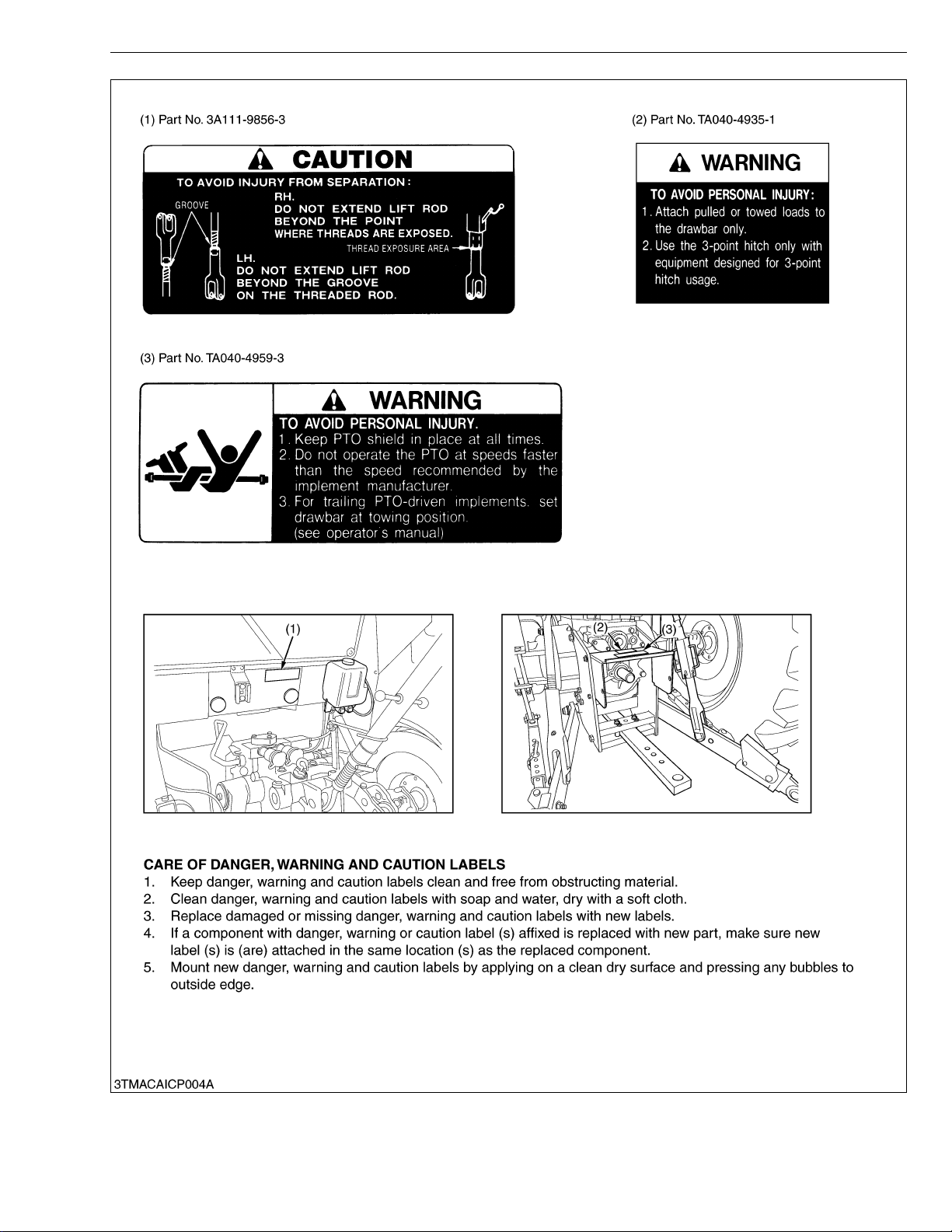
SAFETY DECALS
The following safety decals are installed on the machine. If a decal becomes damaged, illegible or is not on
the machine, replace it. The decal part number is listed in the parts list.
4
M105S, WSM
KiSC issued 03, 2007 A
SAFETY INSTRUCTIONS
5
M105S, WSM
KiSC issued 03, 2007 A
SAFETY INSTRUCTIONS
6
M105S, WSM
KiSC issued 03, 2007 A
SAFETY INSTRUCTIONS
7

M105S, WSM
KiSC issued 03, 2007 A
SPECIFICATIONS
SPECIFICATIONS
Model
Model V3800-DI-TI
Type Vertical, water-cooled, 4-cycle diesel engine
No. of cylinder 4
Total displacement 3769 cm
Bore and stroke 100 × 120 mm (3.9 x 4.7 in.)
Net power 78.3 kW (105 HP)* / 2600 min
Engine
Dimensions
Weight *2 3920 kg (8642 lbs)
Traveling
system
Hydraulic
system
PTO system
Traction system Swing drawbar, adjustable in direction
NOTE : * Manufacture's estimate.
*1 The company reserves the right to change the specifications without notice.
*2 W/O cast iron disks for rear wheels.
*3 Cast iron disks available for wheels.
*4 At lower link end with links horizontal.
PTO power *1 (factory
observed)
Maximum torque 355 N·m (36.2 kgf·m, 261.8 ft-lbs) / 1400 to 1600 min
Battery 12 V, RC, 160 min, CCA 900 A
Fuel Diesel fuel No.1 [below −10 °C (14 °F), Diesel fuel No.2-D [above −10 °C (14 °F)]
Fuel tank 175 L (46.2 U.S.gals, 38.5 lmp.gals)
Engine crankcase 10.7 L (11.3 U.S.qts, 9.4 lmp.qts)
Engine coolant 9.1 L (9.6 U.S.qts, 8.0 lmp.qts)
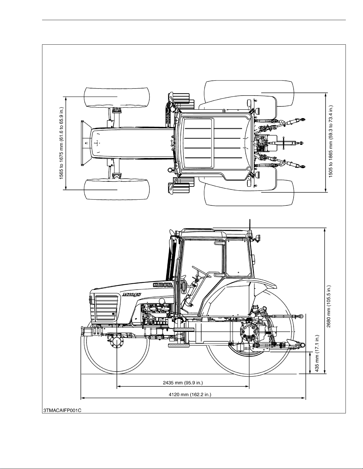
Overall length 4120 mm (162.2 in.)
Overall width (Minimum tread) 2010 mm (79.1 in.)
Overall height 2680 mm (105.5 in.)
Wheel base 2435 mm (95.9 in.)
Tread
Minimum ground clearance 435 mm (17.1 in.) (drawbar bracket)
Standard
tire size *3
Clutch Multiple wet disc hydraulic
Steering Full hydraulic power steering
Transmission Hydraulic shuttle shift, fully synchronized main shift, 32F / 32R, If equip creep gear 48F / 48R
Brake
Differential Bevel gears with differential lock (Front, Rear)
Hydraulic control system Position, draft and mix control
Pump capacity 65.0 L/min. (17.2 U.S.gals./min., 14.3 lmp.gals./min.)
Three point hitch Cat egory II
Max. lifting
force
System pressure 19.6 MPa (200 kgf/cm
Independent clutch Wet type, multiple discs
Live PTO
Front 1565 to 1675 mm (61.6 to 65.9 in.)
Rear 1505 to 1865 mm (59.3 to 73.4 in.)
Front 340 / 85R24 (13.6R24)
Rear 460 / 85R34 (18.4R34)
Travelling Wet type multiple discs (hydraulic)
Parking Wet type multiple discs (mechanical)
At lifting point *4
24 in. behind
lifting point *4
Direction of
turning
PTO speed
2100 kg (4630 lbs) at 610 mm (24 in.) behind lifting point
69.4 kW (93 HP)*1 / 2600 min
2700 kg (5952 lbs) at lower link end with link horizontal
4000 kg (8818 lbs) with 2 assist cylinder
3400 kg (7490 lbs) with 2 assist cylinder
Clockwise, viewed from tractor rear
-1
540 min
-1
540 min
M105S
4WD
3
(230.0 cu.in.)
−1
(rpm)
−1
(rpm)
2
, 2847 psi)
(rpm) at 2205 engine min-1(rpm)
(rpm) at 1519 engine min-1(rpm)
−1
(rpm)
W10281170
8
M105S, WSM
KiSC issued 03, 2007 A
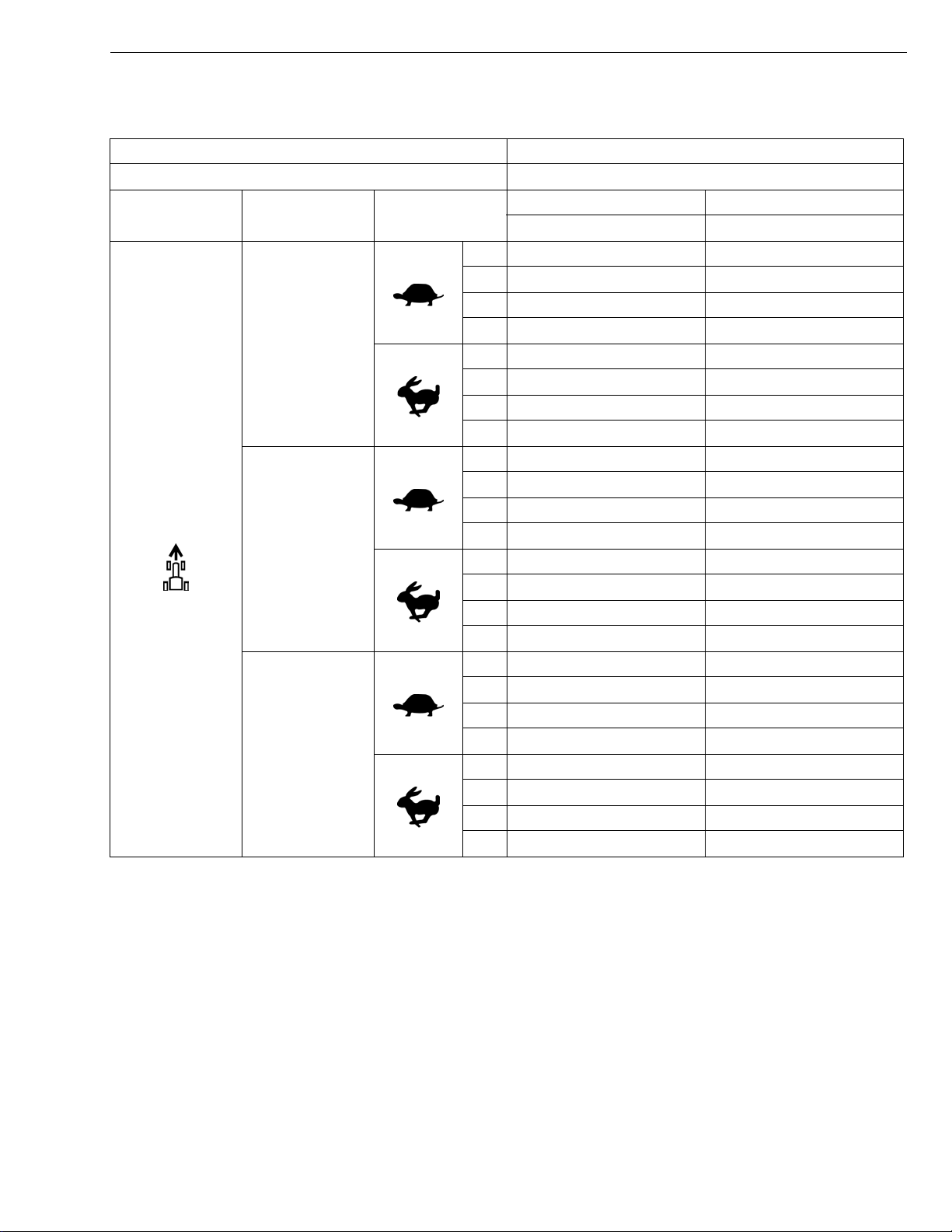
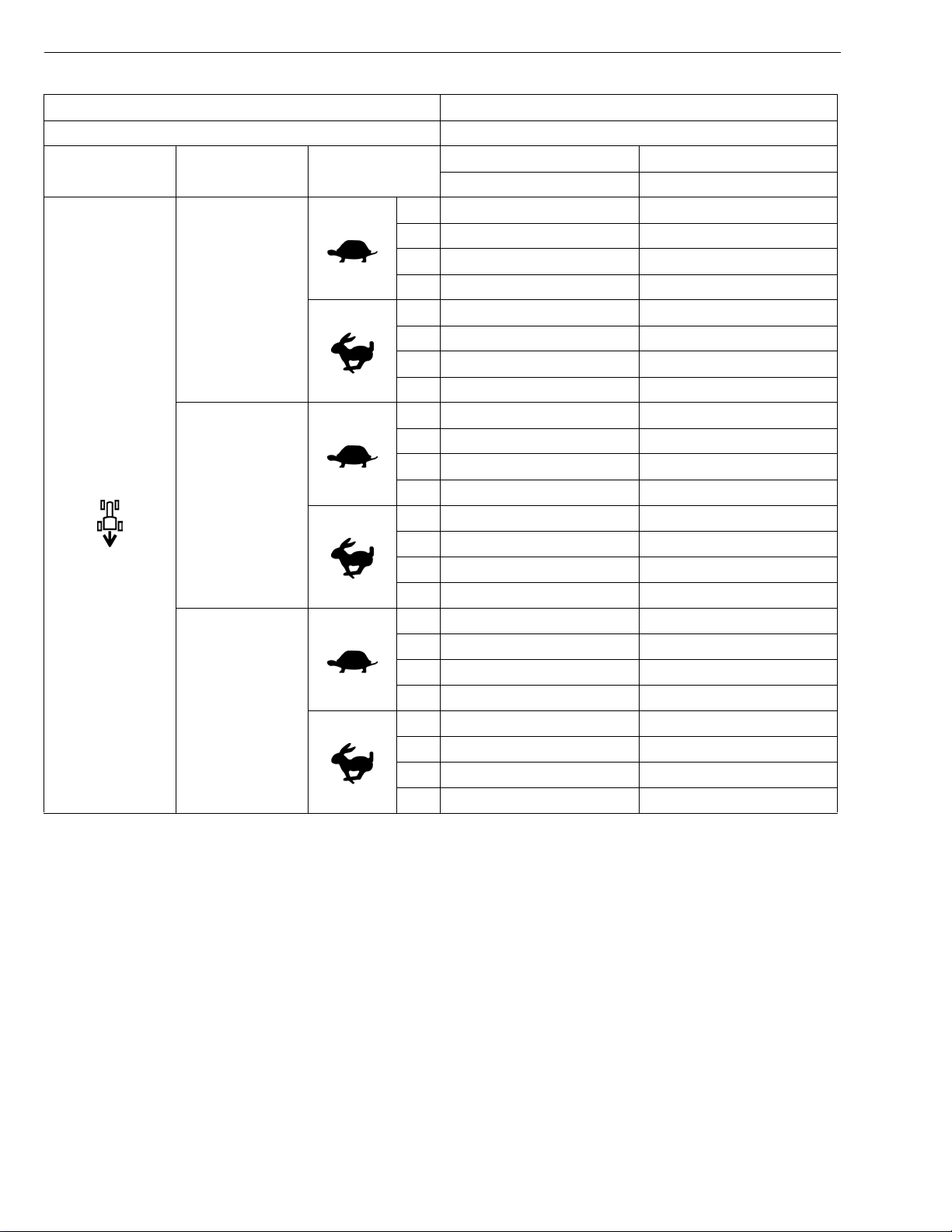
TRAVELING SPEEDS
Model M105S
Tire size (Rear) 460 / 85R34 (18.4R34)
Shuttle shift
lever
Forward
The company reserves the right to change the spe cifi ca tion s with out notic e.
* At maximum engine rpm.
Range gear shift
lever
CREEP
(option)
L:
H
Main gear shift
lever
1 0.36 (0.22) 0.30 (0.19)
2 0.46 (0.29) 0.38 (0.24)
3 0.57 (0.35) 0.47 (0.29)
4 0.72 (0.45) 0.60 (0.37)
1 0.92 (0.57) 0.76 (0.47)
2 1.18 (0.73) 0.97 (0.60)
3 1.45 (0.90) 1.20 (0.75)
4 1.84 (1.14) 1.52 (0.94)
1 2.02 (1.26) 1.67 (1.04)
2 2.57 (1.60) 2.13 (1.32)
3 3.17 (1.97) 2.62 (1.63)
4 4.02 (2.50) 3.33 (2.07)
1 5.15 (3.20) 4.26 (2.65)
2 6.56 (4.08) 5.42 (3.37)
3 8.08 (5.02) 6.68 (4.15)
4 10.27 (6.38) 8.49 (5.28)
1 7.05 (4.38) 5.83 (3.62)
2 8.98 (5.58) 7.43 (4.62)
3 11.06 (6.87) 9.15 (5.69)
4 14.06 (8.74) 11.63 (7.22)
1 17.99 (11.18) 14.87 (9.24)
2 22.92 (14.24) 18.94 (11.77)
3 28.22 (17.54) 14.50 (14.50)
4 38.64 (24.00)* 29.66 (18.43)
Dual Speed : Hi Dual Speed : Lo
km/h (mph) km/h (mph)
TRAVELING SPEEDS
(At rated engine rpm)
W1035065
9
M105S, WSM
KiSC issued 03, 2007 A
Model M105S
Tire size (Rear) 460 / 85R34 (18.4R34)
Shuttle shift
lever
Range gear shift
lever
Main gear shift
lever
Dual Speed : Hi Dual Speed : Lo
km/h (mph) km/h (mph)
1 0.36 (0.22) 0.30 (0.19)
2 0.46 (0.29) 0.38 (0.24)
3 0.57 (0.35) 0.47 (0.29)
CREEP
(option)
4 0.73 (0.45) 0.60 (0.37)
1 0.93 (0.58) 0.77 (0.48)
2 1.19 (0.74) 0.98 (0.61)
3 1.46 (0.91) 1.21 (0.75)
4 1.86 (1.16) 1.53 (0.95)
1 2.04 (1.27) 1.68 (1.04)
2 2.59 (1.61) 2.14 (1.33)
Reverse
3 3.19 (1.98) 2.64 (1.64)
4 4.06 (2.52) 3.36 (2.09)
L:
1 5.19 (3.22) 4.29 (2.67)
2 6.61 (4.11) 5.47 (3.40)
3 8.15 (5.06) 6.74 (4.19)
4 10.36 (6.44) 8.56 (5.32)
1 7.11 (4.42) 5.88 (3.65)
2 9.06 (5.63) 7.49 (4.65)
3 11.16 (6.93) 9.22 (5.73)
4 14.18 (8.81) 11.73 (7.29)
H
1 18.15 (11.28) 15.00 (9.32)
2 23.11 (14.36) 19.11 (11.87)
3 28.47 (17.69) 23.53 (14.62)
4 38.97 (24.21)* 29.92 (18.59)
The company reserves the right to change the specifications without notice.
* At maximum engine rpm.
TRAVELING SPEEDS
(At rated engine rpm)
W1033594
10
M105S, WSM
KiSC issued 03, 2007 A
DIMENSIONS
DIMENSIONS
11

G GENERAL
KiSC issued 03, 2007 A

GENERAL
KiSC issued 03, 2007 A
CONTENTS
1. TRACTOR IDENTIFICATION ......................................................................... G-1
2. GENERAL PRECAUTIONS ............................................................................ G-2
3. HANDLING PRECAUTIONS FOR ELECTRICAL PARTS AND WIRING..G-3
[1] WIRING...................................................................................................... G-3
[2] BATTERY................................................................................................... G-5
[3] FUSE.......................................................................................................... G-5
[4] CONNECTOR............................................................................................ G-6
[5] HANDLING OF CIRCUIT TESTER......................................................... G-7
4. LUBRICANTS, FUEL AND COOLANT ......................................................... G-8
5. TIGHTENING TORQUES ............................. ....... ...... ....... ...... ....... ...... ....... .. G-10
[1] GENERAL USE SCREWS, BOLT AND NUTS................................... G-10
[2] STUD BOLTS.......................................................................................... G-10
[3] HYDRAULIC FITTINGS.......................................................................... G-11
6. MAINTENANCE............................................................................................. G-12
7. CHECK AND MAINTENANCE......... ...... ...... ....... ...... ....... ...... ....... ............... G-14
[1] DAILY CHECK........................................................................................ G-14
[2] CHECK POINT OF INITIAL 50 HOURS ............................................. G-15
[3] CHECK POINTS OF EVERY 50 HOURS........................................... G-18
[4] CHECK POINTS OF EVERY 100 HOURS......................................... G-19
[5] CHECK POINTS OF EVERY 200 HOURS......................................... G-25
[6] CHECK POINTS OF EVERY 300 HOURS......................................... G-29
[7] CHECK POINTS OF EVERY 400 HOURS......................................... G-30
[8] CHECK POINTS OF EVERY 600 HOURS......................................... G-30
[9] CHECK POINTS OF EVERY 800 HOURS......................................... G-33
[10]CHECK POINTS OF EVERY 1 YEAR................................................ G-33
[11]CHECK POINTS OF EVERY 2 YEARS.............................................. G-34
[12]OTHERS .................................................................................................. G-38
8. SPECIAL TOOLS.......................................................................................... G-43
[1] SPECIAL TOOLS FOR ENGINE .......................................................... G-43
[2] SPECIAL TOOLS FOR TRACTOR....................................................... G-60
9. TIRES............................................................................................................. G-74
[1] TYPE OF TIRES.................................................................................... G-74
[2] TREAD ADJUSTMENT........................................................................... G-74
(1) Front Wheel ....................................................................................... G-74
(2) Rear Wheel........................................................................................ G-76
[3] WHEEL HUB........................................................................................... G-77
[4] TIRE PRESSURE................................................................................... G-77
[5] TIRE LIQUID INJECTION...................................................................... G-78
10. IMPLEMENT LIMITATIONS.......................................................................... G-82
M105S, WSM
KiSC issued 03, 2007 A
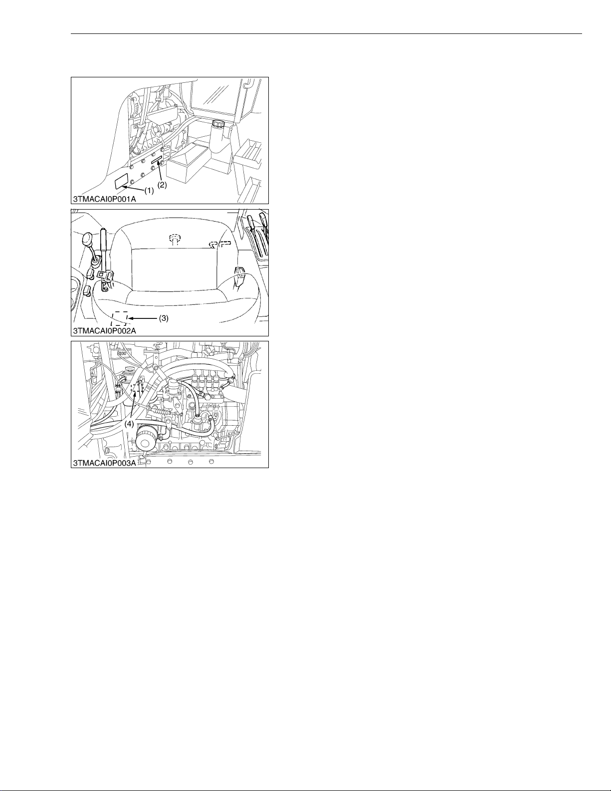
1. TRACTOR IDENTIFICATION
When contacting your loca l KUBOTA distr ibutor, alway s specify
engine serial number, tractor serial number and hour meter reading.
(1) T ractor Identification Plate
(2) T ractor Serial Number
G GENERAL
(3) CABIN Identification Plate
(CABIN Serial Number)
(4) Engine Serial Number
W1010602
G-1
M105S, WSM
KiSC issued 03, 2007 A
2. GENERAL PRECAUTIONS
• During disa ssembly, ca refully ar range removed parts in a cle an
area to prevent confusion later. Screws, bolts and nuts should be
installed in their original position to prevent reassembly errors.
• When special tools are requi red, use KUBOT A genuine speci al
tools. Special tools which are not frequently used should be
made according to the drawings provided.
• Before disassembling or servicing electrical wires, always
disconnect the ground cable from the battery first.
• Remove oil and dirt from parts before measuring.
• Use only KUBOTA genuine parts for parts replacement to
maintain machine performance and to assure safety.
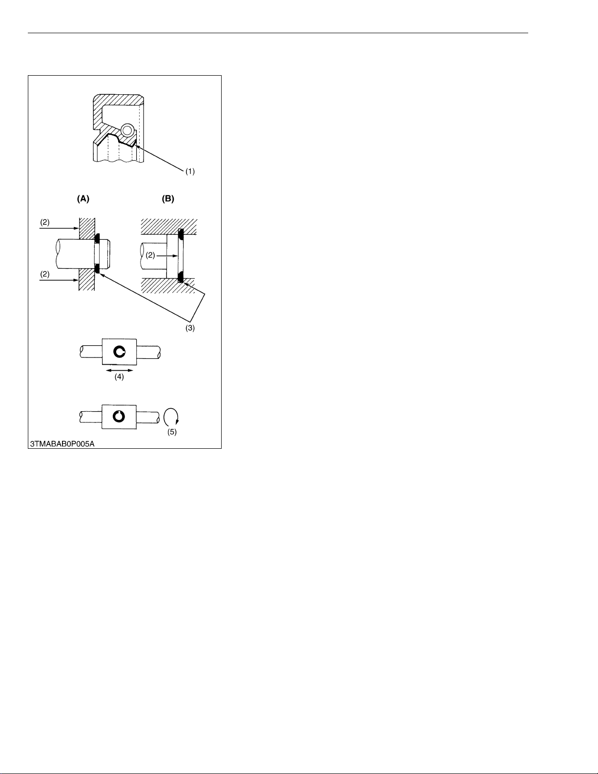
• Gaskets and O-rings must be replaced during reassembly. Apply
grease to new O -rings or oil seals bef ore assembling. See the
figure left side.
• When reassem bling external snap rings or inte rnal snap rings,
they must be positioned so that sharp edge faces against the
direction from which a force is applied. See the figure left side.
• When insert ing spring pins, their splits must face the direction
from which a force is applied. See the figure left side.
• To prevent dam age to the hydraulic s ystem, use only sp ecified
fluid or equivalent.
(1) Grease
(2) Force
(3) Sharp Edge
(4) Axial Force
(5) Rotating Movement
G GENERAL
(A) External Snap Ring
(B) Internal Snap Ring
W1010904
G-2
M105S, WSM
IMPORTANT■
KiSC issued 03, 2007 A
G GENERAL
3. HANDLING PRECAUTIONS FOR ELECTRICAL PARTS
AND WIRING
To ensure safety and prevent damage to the machine and
surrounding equipm ent, heed the following pr ecautions in handling
electrical parts and wiring.
• Check electrical wiring for damage and loosened
connection every year. To this end, educate the customer to
do his or her own check and at the s ame time recommend
the dealer to perform periodic check for a fee.
• Do not attempt to modify or remodel any electrical parts and
wiring.
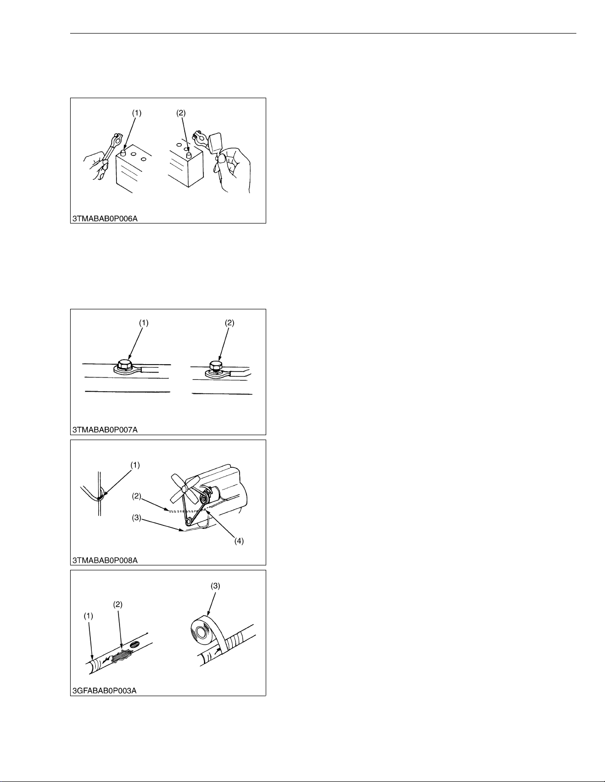
• When removing th e ba tter y cab le s, dis co nn ect t he n egat ive
cable first. When in stalling the b attery cables, c onnect the
positive cable first.
(1) Negative Terminal (2) Positive Terminal
W1011114
[1] WIRING
• Securely t ighten wiring terminals.
(1) Correct
(Securely Tighten)
(2) Incorrect
(Loosening Leads to Faulty Contact)
W1011216
• Do not let wiring contact dangerous part.
(1) Dangerous Part
(2) Wiring (Incorrect)
(3) Wiring (Correct)
(4) Dangerous Part
• Repair or change torn or aged wiring immediately.
(1) Aged
(2) Torn
(3) Insulating Vinyl Tape
W1011313
W1012292
G-3
M105S, WSM
KiSC issued 03, 2007 A
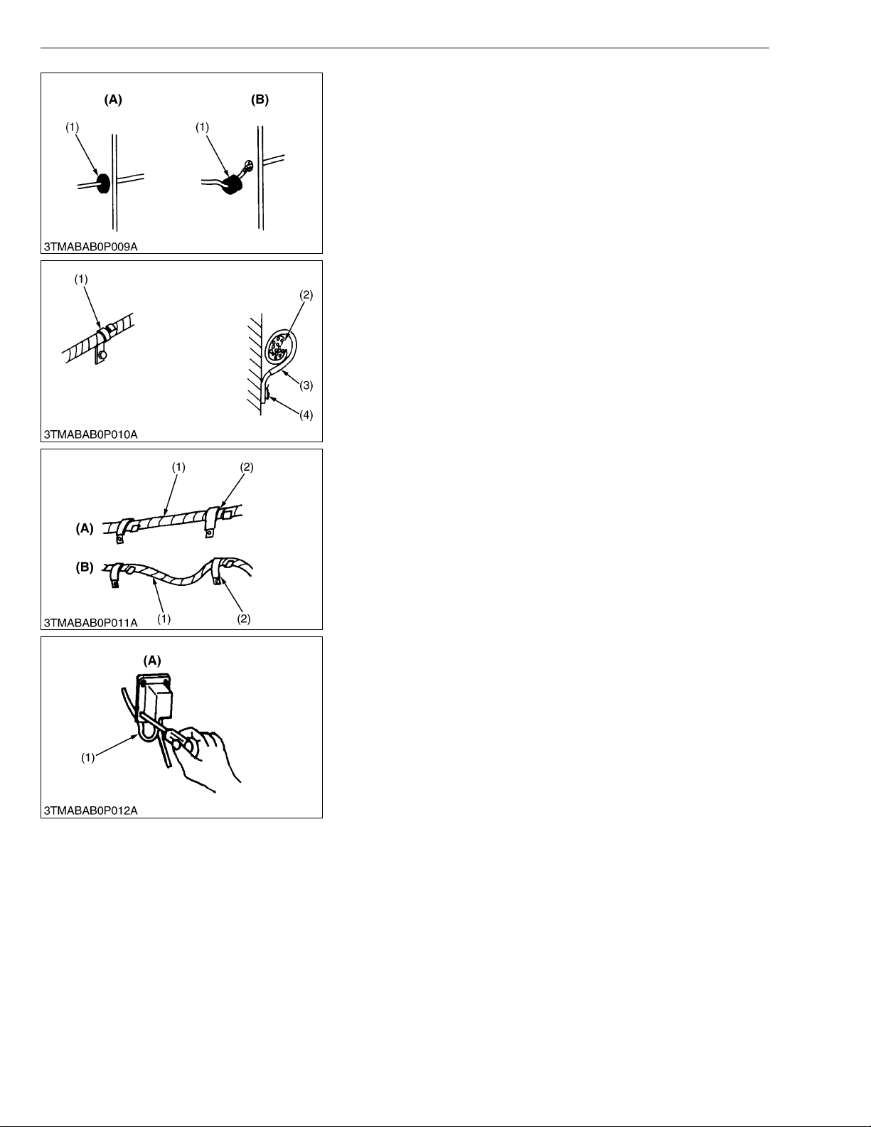
• Securely insert gro mm et.
(1) Grommet (A) Correct
(B) Incorrect
• Securely clamp, being careful not to damage wiring.
(1) Clamp
• Wind Clamp Spirally
(2) Wire Harness
(3) Clamp
(4) Welding Dent
G GENERAL
W1011388
W1011458
• Clamp wiring so that there is no twist, unnecessary sag, or
excessive tension, except for movable part, where sag be
required.
(1) Wiring
(2) Clamp
(A) Correct
(B) Incorrect
W1011587
• In installing a part, take care not to get wiring caught by it.
(1) Wiring (A) Incorrect
W1011670
G-4
M105S, WSM
KiSC issued 03, 2007 A
[2] BATTERY
G GENERAL
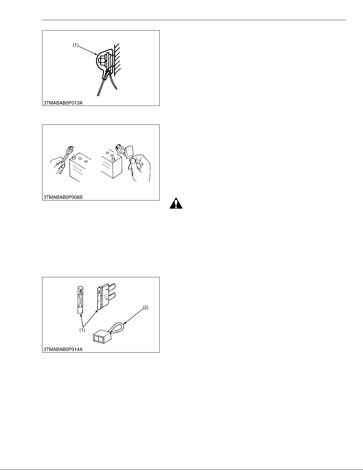
• After installing wiring, check protection of terminals and clamped
condition of wiring, only connect battery.
(1) Cover
• Securely Install Cover
W1011735
• Take care not to confuse positive and negative terminal posts.
• When removing b attery cables, disconnect negative cable first.
When installing battery cables, check for polarity and connect
positive cable first.
• Do not install a ny battery with capacity other than is specified
(Ah).
• After connecting cables to battery terminal posts, apply high
temperature grease to them a nd sec urely in stall t erminal covers
on them.
• Do not allow dirt and dust to collect on battery.
[3] FUSE
CAUTION
• Take care not to let battery liquid spill on your skin and
clothes. If contaminated, wash it off with water immediately.
• Before recharging the battery, remove it from the machine.
• Before recharging, remove cell caps.
• Do recharging in a well- ventilated place where there is no
open flame nearby, as hydrogen gas and oxygen are formed.
W1011816
• Use fuses with specified capacity.
Neither too large or small capacity fuse is acceptable.
• Never use steel or copper wire in place of fuse.
• Do not install working light, radio set, etc. on machine which is not
provided with reserve power supply.
• Do not install accessories if fuse capacity of reserve power
supply is exceeded.
(1) Fuse (2) Slow Blow Fuse
W1012092
G-5
M105S, WSM
KiSC issued 03, 2007 A
[4] CONNECTOR
G GENERAL
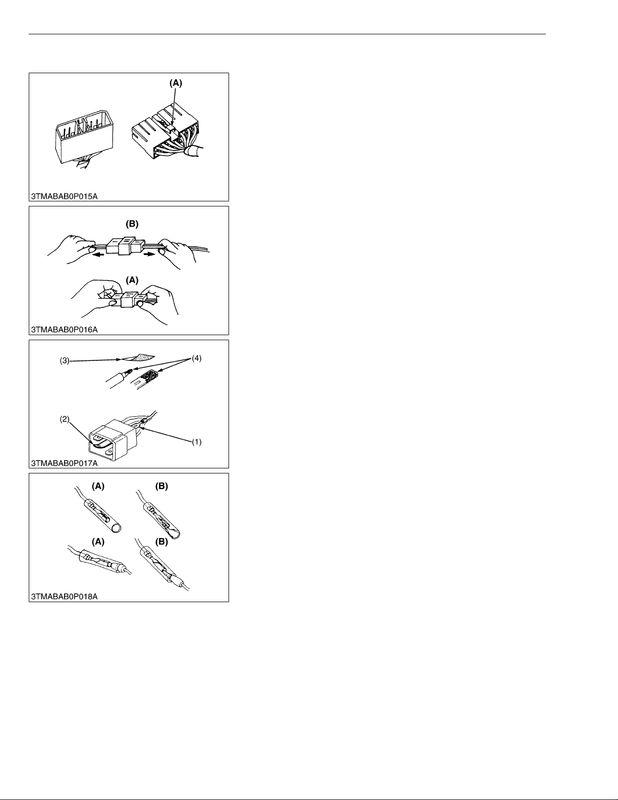
• For connector with lock, push lock to separate.
(A) Push
W1012211
• In separating connectors, do not pull wire harnesses.
• Hold connector bodies to separate.
(A) Correct (B) Incorrect
W1012272
• Use sandpaper to remove rust from terminals.
• Repair deformed terminal. Make certain there is no terminal
being exposed or displaced.
(1) Exposed Terminal
(2) Deformed Terminal
(3) Sandpaper
(4) Rust
W1012346
• Make certain that there is no female connector being too open.
(A) Correct (B) Incorrect
W1012430
G-6
M105S, WSM
KiSC issued 03, 2007 A
• Make certain plastic cover is large enough to cover whole
connector.
(1) Cover (A) Correct
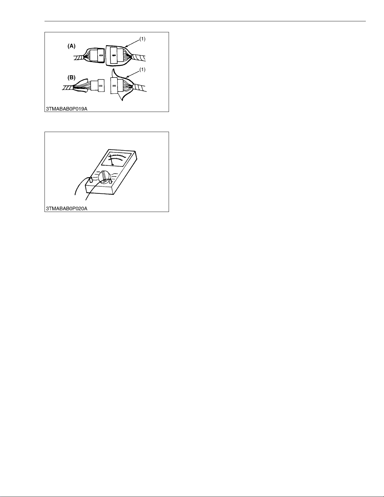
[5] HANDLING OF CIRCUIT TESTER
• Use tester correctly following manual provided with tester.
• Check for polarity and range.
G GENERAL
(B) Incorrect
W1012519
W1012684
G-7

M105S, WSM
KiSC issued 03, 2007 A
4. LUBRICANTS, FUEL AND COOLANT
G GENERAL
Place
1 Fuel tank
Engine block
radiator
2Coolant
Reserve tank
3 Engine crankcase
4 Transmission case
5 Front differential case oil
6 Front axle gear case oil
Brake system
7
(Reservoir and lines)
Air conditioner compressor
8
Refrigerant
* KUBOTA original transmission hydraulic fluid.
** PAG : Polyalkyleneglycol (Syn thetic oil)
Capacity
M105S
175 L
46.2 U.S.gals
38.5 lmp.gals
9.1 L
9.6 U.S.qts
8.0 lmp.qts
1.1 L
1.2 U.S.qts
1.0 lmp.qts
10.7 L
11.3 U.S.qts
9.4 lmp.qts
60 L
63.4 U.S.qts
52.8 lmp.qts
7.0 L
7.4 U.S.qts
6.2 lmp.qts
3.5 L
3.7 U.S.qts
3.1 lmp.qts
0.3 L
0.32 U.S.qts
0.26 lmp.qts
3
50 to 70 cm
0.053 to 0.074 U.S.qts
0.044 to 0.062 Imp.qts
1.1 kg
2.43 lbs
Lubricants, fuel and coolant
No. 2-D diesel fuel
No. 1-D diesel fuel if temperature is
below -10 °C (14 °F)
Fresh clean water with anti-freeze
Engine oil: API service classification
CD, CE or CF
Below 0 °C (32 °F) :
SAE10W, 10W-30 or 10W-40
0 to 25 °C (32 to 77 °F):
SAE20, 10W-30 or 10W-40
Above 25 °C (77 °F):
SAE30, 10W-30 or 10W-40
KUBOT A UDT or KUB OT A SUPER
UDT fluid*
KUBOTA UDT or KUBOTA SUPER
UDT fluid or SAE80, 90 gear oil
KUBOTA UDT or SUPER UDT fluid*
or Turbine oil 32 (see below)
[regular type, multipurpose straight
mineral oil
Mobile DTE Oil #32
TEXACO Regal Oil #32
CHEVRON-GST Oil #32
TERESSO Oil #32]
Never use automotive brake oil.
Compressor oil:
DENSO Suniso
ND-OIL8 <**PAG OIL>
Refrigerant R-134a
G-8

M105S, WSM
NOTE■
KiSC issued 03, 2007 A
G GENERAL
Greasing
Place No. of greasing point Capacity Type of grease
Top link 2
Lift rod (Upper right, lower
right, lower left)
Front axle gear case support 2
9
3
Until grease
overflow
Multipurpose
type grease
Front axle support 2
Steering joint shaft 1
Battery terminal 2 A small amount
• Engine Oil : Oil used in the engine should have an American Petroleum Institute (API) service classification
and Proper SAE Engine Oil according to the ambient temperature as shown above.
• With the emission con trol now in e ffect, the CF -4 and CG-4 lub ricating oils have been d eveloped fo r use
of a low-sulfur fuel on on-road vehicle engines. When an off-road vehicle engine runs on a high-sulfur fuel,
it is advisable to employ the CF, CD or CE lubricating oil with a high total base number. If the CF-4 or CG4 lubricating oil is used with a high-sulfur fuel, change the lubricating oil at shorter intervals.
• Lubricating oil recommended when a low-sulfur or high-sulfur fuel is employed.
O : Recommendable X : Not Recommendable
Lubricating oil class
Remark
Low-sulfur High-sulfur
CF ❍❍TBN greater or equal 10
CF-4 ❍ X
CG-4 ❍ X
• Transmission Oil : The oil used to lubricate the transmission is also used as hydraulic fluid. To insure
proper operation of the hydraulic system and complete lubrication of the t ransmission, it is important that
a multi-grade transmission fluid be used in this system. We recommend the use of KUBOTA SUPER UDT
fluid for optimum protection and performance.
Do not mix different brands together.
• Indicated capacity of water and oil are manufacture's estimate.
Fuel
G-9

M105S, WSM
KiSC issued 03, 2007 A
G GENERAL
5. TIGHTENING TORQUES
[1] GENERAL USE SCREWS, BOLT AND NUTS
Screws, bolt and nuts whose tighten ing torque are not specified in this Workshop Manual s hould be tightened
according to the table below.
Indication on top of
bolt
Material of bolt SS400, S20C S43C, S48C
Material of oppone n t
part
Unit
Diameter
M6
(6 mm, 0.24 in.)
M8
(8 mm, 0.31 in.)
M10
(10 mm, 0.39 in.)
M12
(12 mm, 0.47 in.)
M14
(14 mm, 0.55 in.)
M16
(16 mm, 0.63 in.)
M18
(18 mm, 0.71 in.)
M20
(20 mm, 0.79 in.)
No-grade or 4T 7T 9T
SCr435,
SCM435
Ordinariness Aluminum Ordinariness Aluminum Aluminum
N·m kgf·m ft-lbs N·m kgf·m ft-lbs N·m kgf·m ft-lbs N·m kgf·m ft-lbs N·m kgf·m ft-lbs
7.85
0.80
5.79
7.85
0.80
5.79
9.81
1.00
7.24
7.85
0.80
5.79
12.3
to
9.31
17.7
to
20.5
39.3
to
45.1
62.8
to
72.5
108
to
125
167
to
191
246
to
284
334
to
392
to
0.95
1.8
to
2.1
4.0
to
4.6
6.4
to
7.4
11.0
to
12.8
17.0
to
19.5
25.0
to
29.0
34.0
to
40.0
to
6.87
13.1
to
15.1
29.0
to
33.2
46.3
to
53.5
79.6
to
92.5
123
to
141
181
to
209
246
to
289
to
to
to
8.82
0.90
6.50
16.7
19.6
31.4
34.3
1.7
12.3
to
to
2.0
3.2
to
3.5
–––
–––
–––
–––
–––
to
14.4
23.2
to
to
25.3
to
11.2
23.6
to
27.4
48.1
to
55.8
77.5
to
90.1
124
to
147
197
to
225
275
to
318
368
to
431
to
1.15
2.4
to
2.8
4.9
to
5.7
7.9
to
9.2
12.6
to
15.0
20.0
to
23.0
28.0
to
32.5
37.5
to
44.0
to
8.31
17.4
to
20.2
35.5
to
41.2
57.2
to
66.5
91.2
to
108
145
to
166
203
to
235
272
to
318
to
to
to
8.82
0.90
6.50
17.7
20.5
39.3
44.1
62.8
72.5
1.8
13.1
to
to
2.1
4.0
to
4.5
6.4
to
7.4
–––
–––
–––
–––
to
15.1
29.0
to
to
32.5
46.3
to
to
53.5
to
14.2
29.5
to
34.3
60.9
to
70.6
103
to
117
167
to
196
260
to
304
344
to
402
491
to
568
1.25
to
1.45
3.0
to
3.5
6.2
to
7.2
10.5
to
12.0
17.0
to
20.0
26.5
to
31.0
35.0
to
41.0
50.0
to
58.0
W1034542
9.05
to
10.5
21.7
to
25.3
44.9
to
52.1
76.0
to
86.8
123
to
144
192
to
224
254
to
296
362
to
419
[2] STUD BOLTS
Material of opponet
part
Unit
Diameter
M8
(8 mm, 0.31 in.)
M10
(10 mm, 0.39 in.)
M12
(12 mm, 0.47 in.)
Ordinariness Aluminum
N·m kgf·m ft-lbs N·m kgf·m ft-lbs
11.8
to
15.6
24.6
to
31.3
29.5
to
49.0
1.2
to
1.6
2.5
to
3.2
3.0
to
5.0
8.68
8.82
to
11.5
18.1
23.1
21.7
36.1
to
11.8
19.7
to
to
25.4
to
31.4 3.2 23.1
0.90
to
1.2
2.0
to
2.6
6.51
to
8.67
14.5
to
18.8
W1048139
G-10

M105S, WSM
KiSC issued 03, 2007 A
[3] HYDRAULIC FITTINGS
■ Hydraulic Hose Fittings
G GENERAL
Hose size Thread size
02 1/8 13.7 to 15.7 1.4 to 1.6 10.1 to 11.6
03
04
05
06
■ Hydraulic Pipe Cap Nuts
Pipe size
φ4 × t1.0 19.6 to 29.4 2.0 to 3.0 14.5 to 21.7
φ6 × t1.0 24.5 to 34.3 2.5 to 3.5 18.1 to 25.3
φ8 × t1.0 29.4 to 39.2 3.0 to 4.0 21.7 to 28.9
φ10 × t1.0 39.2 to 49.0 4.0 to 5.0 28.9 to 36.1
φ12 × t1.5 49.0 to 68.6 5.0 to 7.0 36.1 to 50.6
φ15 × t1.6 107.9 to 117.7 11.0 to 12.0 79.6 to 86.8
φ18 × t1.6 107.9 to 117.7 11.0 to 12.0 79.6 to 86.8
Tightening torque
N·m kgf·m ft-lbs
1/4 22.6 to 27.5 2.3 to 2.8 16.6 to 20.3
3/8 45.1 to 53.0 4.6 to 5.4 33.3 to 39.0
W1014711
Tightening torque
N·m kgf·m ft-lbs
W1014848
■ Adaptors, Elbows and Nipples
Items Thread size
PF 1/8 44.1 to 53.9 4.5 to 5.5 32.5 to 39.8
POA-PF
(Nipple with O-ring)
PF 1/4 73.5 to 83.4 7.5 to 8.5 54.2 to 61.5
PF 3/8 93.2 to 103.0 9.5 to 10.5 68.7 to 75.9
PF 1/2 112.8 to 122.6 11.5 to 12.5 83.2 to 90.4
PF 1/8 22.6 to 26.5 2.3 to 2.7 16.6 to 19.5
POB-PF
PF 1/4 35.3 to 43.1 3.6 to 4.4 26.0 to 31.8
(Elbow with O-ring
and no nut)
PF 3/8 53.9 to 63.7 5.5 to 6.5 39.8 to 47.0
PF 1/2 73.5 to 83.4 7.5 to 8.5 54.2 to 61.5
PF 1/8 9.8 to 14.7 1.0 to 1.5 7.2 to 10.8
PF 1/4 29.4 to 34.3 3.0 to 3.5 21.7 to 25.3
Adaptor (NPT)
PF 3/8 49.0 to 68.6 5.0 to 7.0 36.2 to 50.6
PF 1/2 68.6 to 88.3 7.0 to 9.0 50.6 to 65.1
Tightening torque
N·m kgf·m ft-lbs
W1015484
G-11

M105S, WSM
KiSC issued 03, 2007 A
6. MAINTENANCE
G GENERAL
Period
No.
Item
1 Engine start system
2 Wheel bolt torque Check ✩✩✩✩✩✩✩✩✩✩✩✩ 50 hrs G-19
Battery condition
3
4 Greasing ✩✩✩✩✩✩100 hrs G-24
Fan belt Adjust
5
Brake pedal Adjust
6
Parking brake lever
7
Air cleaner
element
8
[Double type]
Fuel line
9
Hydraulic oil filter
10
Toe-in
11
12 Fuel tank water
Power steering oil line
13
Radiator hose and clamp
14
Engine oil
15
Water separator Clean
16
Fuel filter Replace
17
Engine oil filter
18
Transmission fluid
19
Front differential case oil
20
Front axle gear case oil Change
21
22 King-pin pivot Adjust ✩ 600 hrs G-32
Brake oil
23
24 Front axle pivot Adjust ✩ 600 hrs G-31
Engine valve clearance
25
Cooling system Flush
26
27 Coolant Change 2 years G-34
Parking brake cable Replace
28
Brake hose
29
Primary
element
Secondary
element
Check
Check ✩✩✩✩✩✩100 hrs *4 G-19
Adjust ✩✩✩✩✩✩100 hrs G-23
Clean ✩✩✩✩✩✩100 hrs *1 G-20
Replace
Replace 1 year G-33
Check
Replace 2 years G-36
Replace ★✩ ✩ ✩200 hrs G-17
Adjust ✩✩✩200 hrs G-26
Drain
Check
Replace 2 years G-36
Check
Replace 2 years G-36
Check ★✩ ✩300 hrs G-15
Replace ★✩600 hrs G-15
Change ★✩600 hrs G-16
Change ★✩600 hrs G-17
Change ✩ 600 hrs G-31
Adjust 800 hrs 1-S13
Replace 2 years G-37
50 100 150 200 250 300 350 400 450 500 550 600
✩✩✩✩✩✩✩✩✩✩✩✩ 50 hrs
✩✩✩✩✩✩100 hrs G-21
✩✩✩✩✩✩100 hrs G-21
✩✩✩✩✩✩100 hrs G-21
★✩600 hrs
Indication on hour meter
✩✩✩200 hrs G-26
✩✩✩200 hrs G-25
✩✩✩200 hrs G-25
✩ 400 hrs G-30
✩ 400 hrs G-30
Since then
every
1 year *2 G-33
2 years G-34
2 years G-37
Impor
-tant
Refer-
ence
page
G-18
G-18
W1035769
G-12

M105S, WSM
IMPORTANT■
KiSC issued 03, 2007 A
G GENERAL
Period
No.
Item
Master cylinder kit
30
31 Equalizer kit
Brake seal 1 and 2
32
33 Fuel system
34 Brake system
35 Clutch housing water Drain G-38
36 Fuse Replace G-41
37 Light bulb Replace G-39
Replace 2 years 5-S11
Replace
Replace 2 years 5-S16
Bleed
Bleed
50 100 150 200 250 300 350 400 450 500 550 600
Indication on hour meter
Service as required
Since then
every
2 years 5-S11
Impor
-tant
W1033488
Refer-
Additional Items for CABIN Type
Period
No.
Item
Inner air filter Clean
1
Fresh air filter Clean
2
Air conditioner condenser Clean
3
Air conditioner drive belt
4
Air conditioner pipes and
5
hoses
CAB isolation cushion
6
Washer liquid
7
Refrigerant (gas)
8
50 100 150 200 250 300 350 400 450 500 550 600
Adjust ✩✩✩200 hrs G-29
Check 1 year G-32
Check 1 year G-32
Add
Check G-42
Indication on hour meter
✩✩✩200 hrs
✩✩✩200 hrs G-28
✩✩✩200 hrs G-28
Service as required
Since then
every
Impor
-tant
Refer-
ence
page
G-38
G-39
ence
page
G-27
G-40
• The jobs indicated by “★” must be doen after the first 50 hours of operation.
• *1 : Air cleaner should be cleaned more often in dusty condition than in normal conditions.
• *2 : Every year or every 6 times of cleaning.
• *3 : Replace only if necessary.
• *4 : When the battery is used for less than 100 hours per year, check the battery condition by reading the indicator annually.
W1036925
G-13

M105S, WSM
KiSC issued 03, 2007 A
G GENERAL
7. CHECK AND MAINTENANCE
CAUTION
• Be sure to check and service the tractor on a flat place with engine shut off, the parking brake on and chock
the wheels.
[1] DAILY CHECK
To prevent trouble fro m occurring, it i s important to k now the condition o f the tractor. Chec k the following i tems
before starting.
Checking
• Check areas where previous trouble was experienced.
• Walk around the tractor.
1. Check the tire pressure, and check for wear and damage.
2. Check for oil and water leak.
3. Check the engine oil level.
4. Check the transmission fluid level.
5. Check the coolant level.
6. Check the brake oil level.
7. Check the washer liquid level.
8. Check the water separator.
9. Check air cleaner evacuator valve (when used in a dusty place).
10.Check the condition of seat belt.
11.Check and clean the radiator screen and grill.
12.Check and clean the air conditioner condenser screen, and intercooler screen.
13.Check the nuts of tires are tight.
14.Check the number plate or SMV emblem for damage and replace as necessary if equipped.
15.Care of danger, warning and caution labels.
16.Clean around the exhaust manifold and the muffler of the engine.
• While sitting in the operator's seat.
1. Check the throttle pedal, brake pedal and clutch pedal.
2. Check the throttle lever and shuttle lever.
3. Check the parking brake.
4. Check the steering wheel.
5. Check the seat belt.
• Turning the key switch.
1. Check the performance of the easy checker lights.
2. Check the head lights, turn signal lights, hazard lights and other light equipment. Clean if necessary.
3. Check the performance of the meters and gauges.
• Starting the engine.
1. Check to see that the lights on the easy checker go off.
2. Check the color of the exhaust gas.
3. Check the brakes for proper operation.
G-14
M105S, WSM
IMPORTANT■
KiSC issued 03, 2007 A
[2] CHECK POINTS OF INITIAL 50 HOURS
Changing Engine Oil
CAUTION
• Before changing oil, be sure to stop the engine.
• Allow engine to cool down sufficiently, oil can be hot and
can burn.
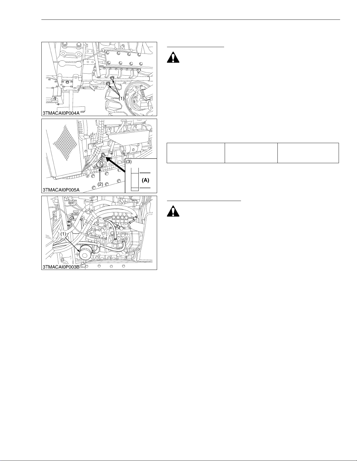
1. To drain the used oil, remove the drain plugs (1) at the bottom of
the engine and drain the oil completely into the oil pan.
All the used oil can be dr ain ed ou t eas ily when th e eng ine is still
warm.
2. After draining reinstall the drain plugs (1).
3. Fill with the new oil up to the upper notch on the dipstick.
Refer to “LUBRICANTS, FUEL AND COOLANT”. (See page
G-8.)
Engine Oil Capacity
G GENERAL
10.7 L
11.3 U.S .qts
9.4 Imp.qts
(1) Drain Plug
(2) Oil Inlet Plug
(3) Dipstick
(A) Oil level is acceptable within this
range.
W1039461
Replacing Engine Oil Filter
CAUTION
• Be sure to stop the engine before changing oil filter
cartridge.
• Allow engine to cool down sufficiently, oil can be hot and
can burn.
1. Remove the oil filter (1).
2. Put a film of clean engine oil on rubber seal of new filter.
3. Tighten the filter quickly until it contacts the mounting surface.
Tighten filter by hand an additional 1/2 turn only.
4. After the new filter h as been replaced, the engine oil no rmally
decreases a little. Make sure that the engine oil does not leak
through the seal and be sure to check the oil level on the dipstick.
Then, replenish the engine oil up to the prescribed level.
• To prevent serious damage to the engine, use only a
KUBOTA genuine filter.
(1) Engine Oil Filter
W1040148
G-15
 Loading...