

Page 1
1502-0195 クボタ K008-3 アメリカ取説(英語) 表紙−オモテ
MODEL
K
008-3
U.S.A . : KUBOTA TRACTOR CO RPORATION
3401
Del Amo Blvd ., T orra nce, CA
90503
, U.S .A.
Telep hone : (
310)370-3370
Canad a : KUBOTA CANADA LTD .
5900 14
th Av enue , Ma rkha m, O ntar io, L3S 4K4, Can ada
Telep hone : (
905)294-7477
Franc e : KUBOTA EUROPE S.A.S
19-25
, Rue Jul es V ercr uyss e, Z .I. BP88,
95101
Arɡe nteu il C edex , Fr ance
Telep hone : (
33)1-3426-3434
Italy : KUBOTA EUROPE S.A .S Italy Branch
Via G rand i,
29 20068
Pesc hier a Bo rrom e (M I) I taly
Telep hone : (
39)02-51650377
Germa ny : KUBOTA BAUMASCHIN EN GmbH
Stein haus er s tr,
100, 66482
Zwei bruc ken Rhei nlan dpfa lz G erma ny
Telep hone : (
49)6332-4870100
U.K. : KUBOTA (U.K.) LTD.
Dorme r Ro ad, Tham e, O xfor dshi re, OX
9 3
UN, U .K.
Telep hone : (
44)1844-214500
Austr alia : KUBOT A TRACTOR AUSTRALIA PTY LTD.
25-29
Perm as W ay, Truɡ anin a, V IC
3029
, Aus tral ia
Telep hone : (
61)-3-9394-4400
Malay sia : SIME KUBOTA SDN. BHD.
No.
3
Jala n Se padu 25/
123
Tama n Pe rind ustr ian Axis ,
Seksy en
25, 40400
Shah Ala m, S elan ɡor Daru l Eh san Malay sia
Telep hone : (
60)3-736-1388
Phili ppin es : KUBOTA PHILIPPINES, INC.
232
Quir ino Hiɡh way, Bae sa, Quez on C ity
1106
, Phi lipp ines
Telep hone : (
63)2-422-3500
Taiwa n : SHIN TAIWAN AGRIC ULTURAL MACHINERY CO., LTD.
16
, Fen ɡpin ɡ 2nd Rd , Ta liao Shi anɡ Kaoh siun ɡ
83107
, Tai wan R.O. C.
Telep hone : (
886)7-702-2333
Thail and : SIAM KUBOTA CORPORATION CO., LTD.
101/19-24
Moo 20, Nav anak orn Indu stri al E stat e, T ambon Khl onɡn uenɡ , Am phur Khl onɡl uanɡ,
Pathu mtha ni
12120
, THA ILAN D
Telep hone : (
66)2-909-0300
Japan : KUBOTA Corporatio n
Farm & In dust rial Mac hine ry I nter natio nal Oper atio ns H eadq uart ers
2-47
, Shi kits uhiɡ ashi 1-chom e, N aniw a-ku , Os aka, Jap an
556-8601
Weste rn D ivis ion :
1175
S. G uild Avc ., L odi, CA
95240
Telep hone : (
209)334-9910
Centr al D ivis ion :
14855
FAA Blvd ., F ort Wort h, T X
76155
Telep hone : (
817)571-0900
North ern Divi sion :
6300
at O ne K ubot a Wa y, G rove port , OH
43125
Telep hone : (
614)835-1100
South east Div isio n :
1025
Nort hbro ok P arkw ay, Suwa nee, GA
30024
Telep hone : (
770)995-8855
English (U.S.A.)
Code No. RA028-8241-8
Page 2
1502-0195 クボタ K008-3 アメリカ取説(英語) 表紙−ウラ
LIST OF ABBREVIATIONS
Abbreviations Description
API
ASTM
DIN
Front
ISO
JIS
L
L/min
MIL
rpm
SAE
ROPS
American Petroleum Institute
American Society for Testing and Materials, USA
German Institute for Standards, Federal Republic of Germany
"Front" means the front view towards the boom and dozer
International Standards Organization
Japanese Industrial Standard
Volume (Litre)
Litre per minute
Military Standards
Revolutions Per minute
Society of automotive Engineering
Roll-Over Protective Structures
California Proposition 65
3 WARNING 3
The engine exhaust from this product
contains chemicals known to the State
of California to cause cancer, birth
defects or other reproductive harm.
K008-3
English (U.S.A.)
AT. C. 9-16. 1. K
&DOLIRUQLD3URSRVLWLRQ
:$ 5 1 ,1 *
(QJLQHH[KDXVWVRPHRILWVFRQVWLWXHQWV
FHUWDLQYHKLFOHFRPSRQHQWVDQGIOXLGV
FRQWDLQRUHPLWFKHPLFDOVNQRZQWRWKH
6WDWHRI&DOLIRUQLDWRFDXVHFDQFHUDQGELUWK
GHIHFWVRURWKHUUHSURGXFWLYHKDUP
Page 3

GENERAL SYMBOLS
The instruments and operation elements have been marked with a series of symbols in order to
simplify the operation of your excavator. These symbols are listed below with the respective
descriptions.
3
Safety alert Symbol
Alarm lamp “Fuel level too low”
•
Alarm lamp “Engine oil pressure”
Alarm lamp
“Water temperature warning”
g Alarm lamp “Battery charge”
5 Horn
R Diesel
E Hydraulic fluid
j Fast
k Slow
Excavator - Overhead movement
toward the front
Excavator - Overhead movement
toward the rear
Boom raise
Boom lower
Arm out
Arm in
Bucket dig / rollback
Bucket dump
Boom swing (left)
Boom swing (Right)
Dozer raise
Dozer lower
Operation direction of control lever
Operation direction of control lever
Read operator’s manual
Lock
Unlock
Reducing / Increasing track width
Page 4

FOREWORD
You are now the proud owner of a KUBOTA excavator. This excavator
is a product of KUBOTA quality engineering and manufacturing. It is
made of quickly fine materials and under rigid quality control systems.
It will give you long, satisfactory service. To obtain the best use of your
excavator, please read this manual carefully. It will help you become
familiar with the operation of the excavator and contains many helpful
hints about excavator maintenance. It is KUBOTA's policy to utilize as
quick as possible every advance in our research. The immediate use of
new techniques in the manufacture of products may cause some small
parts of this manual to be outdated. KUBOTA distributors and dealers
will have the most up-to-date information. Please do not hesitate to
consult with them.
Page 5
SAFETY FIRST
IMPORTANT :
NOTE : Gives helpful information.
DANGER :
WARNING :
CAUTION :
Indicates an imminently hazardous situation
which, if not avoided, will result in death or
serious injury.
Indicates a potentially hazardous situation which,
if not avoided, could result in death or serious
injury.
Indicates a potentially hazardous situation which,
if not avoided, could result in minor or moderate
injury.
Indicates that equipment or property damage
could result if instructions are not followed.
This symbol, the industry's "Safety Alert Symbol", is used throughout this
manual and on labels on the machine itself to warn of the possibility of
personal injury. Read these instructions carefully. It is essential that you
read the instructions and safety regulations before you attempt to
assemble or use this unit.
Page 6

CONTENTS
SAFE OPERATION................. -1
DEALER SERVICE..........................1
TECHNICAL DATA ..........................2
DESCRIPTION OF MACHINE
PARTS..........................................3
INSTRUMENT PANEL AND
CONTROL ELEMENTS................4
BEFORE START .............................6
HANDLING THE SAFETY DEVICES
.....................................................6
Control lever lock .............................6
Swing lock pin..................................6
DAILY CHECKS...............................6
OPERATION OF THE ENGINE ......7
STARTING THE ENGINE................7
Hourmeter........................................9
Checkpoints after Starting the Engine
.....................................................9
STARTING THE ENGINE UNDER
COLD CONDITIONS ....................9
STOPPING THE ENGINE .............10
Engine Stop Lever .........................10
STARTING WITH AN AUXILIARY
BATTERY...................................10
Observe Following Guidelines when
Starting with an Auxiliary Battery.
...................................................11
Precautions in case of overheat.....11
EXCAVATOR OPERATION ..........12
CONTROL OBSERVATIONS
DURING OPERATION ...............12
Stop the Engine immediately if: .....12
Alarm Lamps..................................12
RUNNING-IN OF THE NEW
EXCAVATOR ............................12
Do not Work with Full Revolutions or
Full Loads during the First 50
Working Hours............................12
Oil Change in the Run-in Stage. ...12
STARTING ....................................13
Seat Belt and Adjusting the
Operator's Seat ..........................13
Working Light Switch .....................14
CONTROLS FOR ATTACHMENTS
...................................................14
OPERATION OF THE BOOM........17
OPERATION OF THE ARM...........18
OPERATION OF BUCKET ............18
SWIVEL (UNIT SWING)
OPERATION ..............................19
BOOM SWING OPERATION.........19
BOOM SWING PEDAL ..................20
OPERATION OF TRACK WIDTH
CHANGE AND DOZER..............20
Operation of the Track Width.........20
Operation of the Dozer Width ........21
Operation of the Dozer ..................22
DRIVING........................................22
Drive Levers (Right, Left)...............23
TURNS ..........................................23
Pivot Turn ......................................23
Spin Turn .......................................25
UP AND DOWNHILL TRAVELLING
...................................................25
PARKING ON A SLOPE ................26
DRIVE SPEED PEDAL..................26
SERVICE PORT OPERATION ......26
IMPORTANT INFORMATION ON
EXCAVATOR OPERATION .......27
OPERATING FOLDABLE ROPS...28
To Fold the ROPS .........................28
To Raise the ROPS to Upright
Position.......................................29
Adjustment of Foldable ROPS.......29
TRANSPORTING THE EXCAVATOR
ON A TRUCK .............................30
LIFTING OF THE EXCAVATOR....32
MAINTENANCE.............................34
MAINTENANCE INTERVALS........34
OPENING AND CLOSING OF
PARTS ......................................36
Opening/Closing of the Engine Hood
...................................................36
Page 7

Keep the Tools and Operator's
Manual in the Toolbox ................36
DAILY CHECKS.............................36
Coolant Check ..............................36
Check Fuel Level ...........................37
Check Engine Oil Level..................38
Check Hydraulic Oil Level..............38
Lubrication Points .........................39
Check Radiator ..............................40
Cleaning of Engine and Electrical
Wiring ........................................40
Checking the Electrical Circuit .......40
Washing the Whole Machine .........40
Checking Seat Belt and ROPS ......40
REGULAR CHECKS AND
MAINTENANCE WORK ............41
EVERY 50 SERVICE HOURS ......41
Draining the Water from the Fuel
Tank ...........................................41
Draining of the Fuel Filter ..............41
Battery Service ..............................42
Battery Charging............................42
Greasing of Swing Bearing Teeth .43
EVERY 200 SERVICE HOURS ....43
Checking the Fan Belt Tension......43
Checking the Radiator Hoses ........44
Inspection and Cleaning of the Air
Filter Element .............................44
Air Filter Maintenance ...................45
Greasing of the Swing Bearing .....45
Checking Fuel Line and Intake Air
Line ............................................45
EVERY 500 SERVICE HOURS.....46
Engine Oil Change (Change the
engine oil every 500 hours, or every
1 year in the case that service hour
is less than 500 hours) ...............46
Replacing Engine Oil Filter (Replace
the engine oil filter every 500 hours,
or every 1 year in the case that
service hour is less than 500 hours)
...................................................46
Replacing Fuel Filter Element........47
EVERY 1000 SERVICE HOURS...47
Hydraulic Oil Change (Including
Replacing of the Suction Filter and
the Return Filter in the Hydraulic
Tank) ..........................................47
Hydraulic Oil Check with Hydraulic
Breakers .....................................48
EVERY 1000 SERVICE HOURS OR
ONCE A YEAR ..........................48
Replacing Air Filter Element ..........48
EVERY 1500 SERVICE HOURS...48
Checking Fuel Injection Nozzle
(Injection Pressure) ....................48
EVERY 2000 SERVICE HOURS...48
Changing Front Idler and Track Roller
Oil ...............................................48
Checking the Dynamo and Starter
Motor ..........................................48
EVERY 3000 SERVICE HOURS...49
Checking Injection Pump ...............49
ANNUAL SERVICING ...................49
Electrical Wiring and Fuses ...........49
BIENNIAL SERVICING .................49
Replacement of Radiator Hoses....49
Changing Radiator Coolant ...........49
Replacing Fuel Hose .....................50
Replacing Intake Air Line...............50
OTHER SERVICING......................50
Cleaning the Track Frame Telescopic
Beams ........................................50
OTHER ADJUSTMENTS AND
REPLACEMENTS .....................51
PURGING OF THE FUEL SYSTEM
...................................................51
ADJUSTMENT OF CRAWLERS ...51
Special Information when Using
Rubber Crawlers.........................52
CHANGING THE BUCKET ...........53
FUSES...........................................53
Replacing Fuses ............................53
Fuse Capacities and Circuits ........53
Slow Blow Fuse .............................53
TROUBLESHOOTING...................54
OPERATION IN COLD WEATHER
CONDITIONS ............................56
Page 8

PREPARATION FOR OPERATION
IN COLD WEATHER ..................56
PROCEDURE AFTER WORK
CARRIED OUT ..........................56
LONG STORAGE ..........................57
RECOMMENDED OILS.................59
MAIN DIMENSIONS ......................61
LIFTING CAPACITY .....................62
Page 9

Page 10
-1SAFE OPERATION
SAFE OPERATION
The best insurance against accidents is to abide
by the safety regulations.
Read and understand this section carefully,
before operating the excavator.
Every user, however experienced, should
carefully read and understand this section and
those of the attachments and accessories
before taking the excavator into operation. The
owner is obliged to inform the operators of these
instructions in detail.
Keep this manual in the toolbox.
1. BEFORE OPERATION
1. Make yourself acquainted with the excavator
and be aware of its limits. Read this
operator's manual carefully before starting
the excavator.
2. Obey the danger, warning and caution
labels on the machine.
3. For your safety, ROPS (Roll-Over Protective
Structure) with a seat belt is installed.
Always use seat belt when the machine is
equipped with a ROPS.
Do not modify structual members of ROPS
by welding, drilling, bending, grinding or
cutting, as this may weaken the structure. If
any component is damaged, replace it. Do
not attempt repairs. If ROPS is loosened or
removed for any reason, make certain all
parts are reinstalled correctly. Tighten
mounting bolts to proper torque.
4. The seat belt must be inspected regularly
and replaced if damaged.
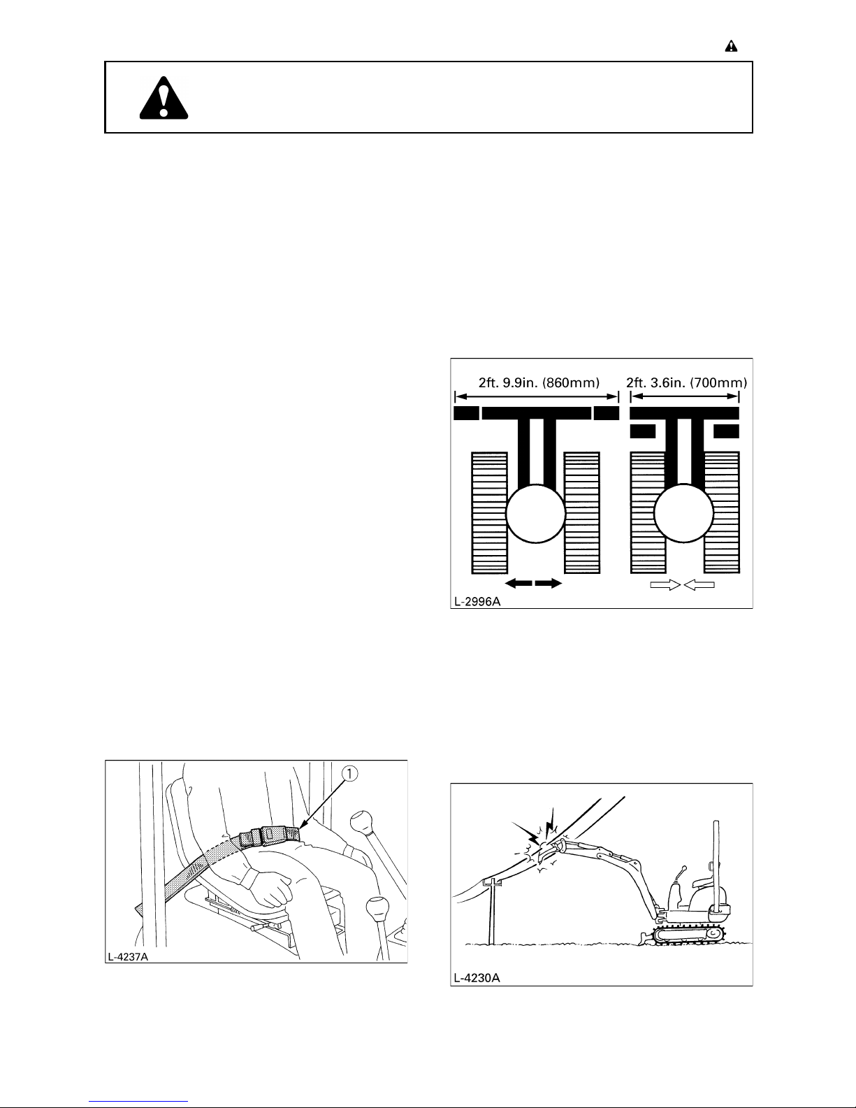
5. Track can be set at the narrow width 2 ft.3.6
in. (700mm) and the standard width 2 ft.9.9
in. (860mm).
(for details see "OPERATION OF TRACK
WIDTH CHANGE AND DOZER")
Do not operate in narrow track width 2 ft.3.6
in. (700mm), there is a risk of the excavator
tipping over, always operate in standard
track width 2 ft.9.9 in. (860mm), except to
pass through a narrow space on even
ground.
6. Do not use the excavator under the
influence of alcohol, medication or other
substances. Fatigue is also dangerous.
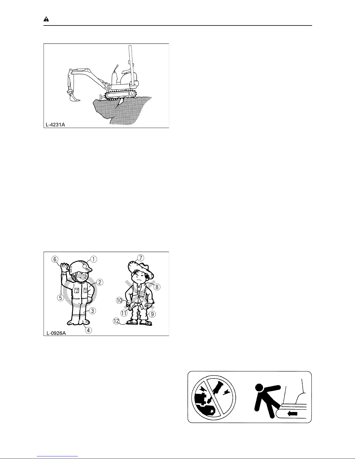
7. Check the surroundings carefully before
using the excavator or when attachments
are being attached.
A Pay attention to the overhead clearance with
electric wires.
A Check for pipes and buried cables.
A Check for hidden holes, hindrances, soft
ground and overhangs.
(1) Seat belt
Page 11
-2 SAFE OPERATION
A During excavator use do not allow any
persons within the working range.
8. Do not allow other persons to use the
machine before having informed him on the
exact operation and work instructions, and
be assured that the operator's manual has
been read and understood.
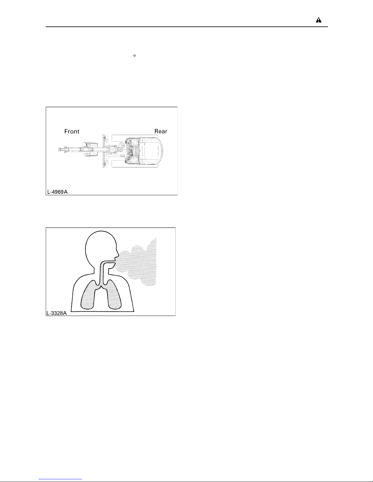
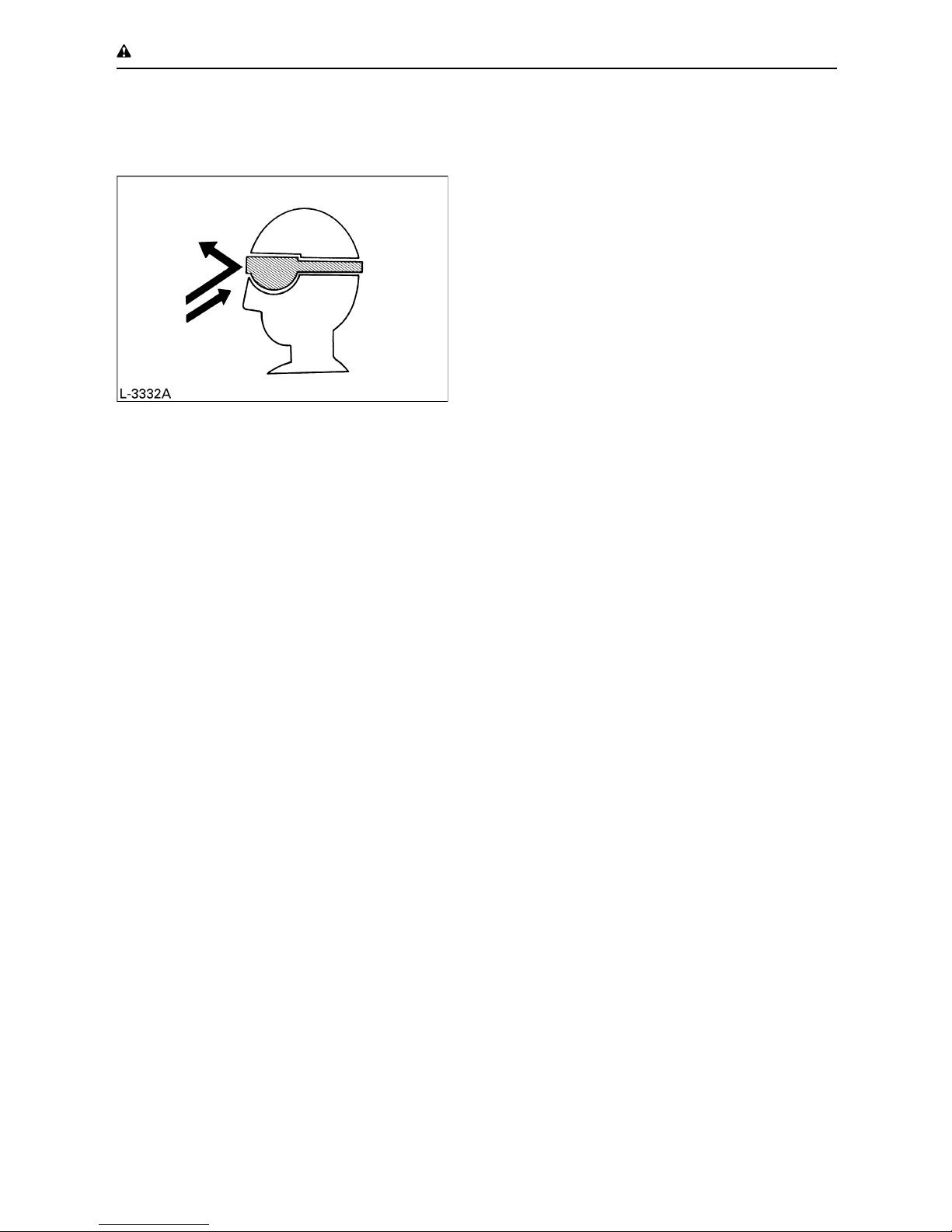
9. Do not wear baggy, torn or too large clothing
when working with the excavator. Clothing
can get caught in rotating parts or control
elements which can cause accidents or
injuries. Wear adequate safety clothing, e.g.
safety helmet, safety shoes, eye protection,
ear protection, working gloves, etc., as
necessary and as prescribed by laws or
statutes.
10.Do not allow passengers to get on any part
of the excavator seat during operation.
11.Check mechanical parts for correct
adjustments and wear. Exchange worn or
damaged parts immediately. Check nuts
and bolts regularly for tight fitment.
(for details see "Care and Maintenance").
12.Keep your excavator clean. Heavy soiling,
grease, dust and grass can inflame and
cause accidents or injuries.
13.Use only KUBOTA authorized attachments.
14.Before starting the excavator, be absolutely
sure that the excavator has been filled with
fuel, lubricated, greased and undergone
other maintenance work.
15.Do not modify the excavator, otherwise it
could lead to unforeseen safety problems.
2. STARTING OF THE EXCAVATOR
1. Get into and out of the machine safely.
Always face the machine. Always use
handrails and available steps and keep
yourself well balanced. Do not hold any of
the control Ievers and switches. Do not jump
on or off the machine, whether stationary or
in motion.
2. Start and control the excavator only from the
operator's seat. The driver should not lean
out of his seat when the engine is running.
3. Before starting the engine, make sure that
all control levers (including auxiliary control
levers) are in their neutral positions.
Before starting the engine, make sure that
the control levers, travel lever, pedals and
other control elements are not stuck and can
be moved smoothly. If stuck, for example, a
lever may fail to return, possibly putting you
in danger. If anything wrong is found,
immediately pinpoint the cause and correct
it.
4. Do not start the engine by jumping the
starter connections. Do not try to circumvent
using the starter switch, otherwise the
engine could start suddenly and the
excavator could move.
(1) Helmet
(2) Clothing fit for work
(3) Tight seams
(4) Good grip footwear
(5) Well fitting cuffs
(6) Working gloves
(7) Straw hat
(8) Towel
(9) Baggy trousers
(10) Loose cuffs on shirt
(11) Baggy shirt
(12) Rubber sandals
Page 12
-3SAFE OPERATION
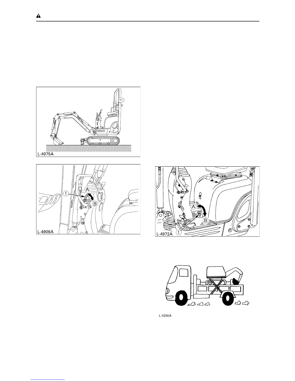
5. Make sure that the dozer is on the front side.
(The dozer must be raised.) If the swing
frame has been turned 180 , i.e. the dozer
is, seen from the operator, "behind", then the
travel direction is opposite to the drive
direction of the levers (when activating the
drive lever forwards, the excavator, seen
from the operator, will move backwards).
6. Do not run the engine in closed or badly
ventilated rooms. Carbon monoxide is
colourless, odourless and deadly.
7. Keep all safety equipment and covers in
place. Replace damaged or missing safety
devices.
8. Precautions against tipping over. In order to
secure safe operation, keep away from
steep slopes and embankments. Do not
swing the bucket downwards. Lower the
dozer during digging. Keep the bucket as
low as possible while driving upwards. Turn
slowly on slopes. Do not keep the excavator
near the edges of trenches and banks, as
the earth can give way due to the weight of
the excavator.
9. Watch out at all times where the excavator is
being moved to. Keep an eye out for
hindrances.
10.Keep enough distance from trench and bank
edges.
C Safety for children
Tragedy can occur if the operator is not alert to
the presence of children. Children generally are
attached to machines and the work they do.
11.Never assume that children will remain
where you last saw them.
12.Keep children out of the work area and
under the watchful eye of another
responsible adult.
13.Be alert and shut your machine down if
children enter the work area.
14.Never carry children on your machine. There
is no safe place for them to ride. They may
fall off and be run over or interfere with your
control of the machine.
15.Never allow children to operate the machine
even under adult supervision.
16.Never allow children to play on the machine
or on the implement.
17.Use extra caution when backing up, look
behind and down-make sure area is clear
before moving.
18.When parking your machine if at all possible
park on a firm, flat and level surface; if not,
park across a slope. Set the parking
brake(s), lower the implements to the
ground, remove the key from the ignition and
lock the cab door (if equipped) and chock the
crawlers or the wheels.
Page 13
-4 SAFE OPERATION
3. AFTER OPERATION
Before leaving the machine,
A Bring the excavator to hard even ground.
A Lower the attachments and the dozer blade
on the ground.
A Stop the engine.
A Lock all control levers.
A Remove the key.
4. SAFE LOADING AND TRANSPORT
OF THE EXCAVATOR
1. Observe all regulations concerning the
transport of excavators on public roads.
2. Use adequately long and robust ramps
when loading on a truck. (for details see
"TRANSPORTING THE EXCAVATOR ON
A TRUCK")
3. Do not change the running direction and to
avoid a tipping over, do not try to swing the
attachment crosswise to the loading ramps.
4. After loading of the excavator on a truck,
engage the swing lock pin.
Lower the attachment on the loading plane
and release the pressure from the hydraulic
system.
Block the crawlers with blocks and wire
down the excavator. After loading the
excavator on a truck, tie down the
undercarriage of the excavator with a strong
steel wire on the truck.
5. Do not brake abruptly with the excavator
loaded. Fatal accidents could happen.
(1) Lock lever (A) "Lock"
(B) "Unlock"
(1) Swing lock pin (A) "Lock"
(B) "Unlock"
Page 14
-5SAFE OPERATION
6. If the excavator is to tow another machine,
the load must be smaller than the strength of
the hook.
5. MAINTENANCE
Before doing maintenance work on the
excavator, place the machine on even solid
ground, Iower the attachments on the ground,
stop the engine and release the cylinder
pressure by actuating the levers. When
dismantling hydraulic parts, make sure that the
hydraulic oil has cooled down sufficiently to
avoid burns.
Start maintenance work carefully, e.g. loosen
screws slowly so that oil will not squirt out.
1. Before doing work on the engine, the
exhaust system, the radiator and the
hydraulics, let the excavator cool down
sufficiently.
2. Turn off the engine at all times when filling
with fuel. Avoid spilling and over-filling of
fuel.
3. Smoking is prohibited while fuelling and
handling the battery! Keep sparks and fire
away from the fuel tank and battery.
Flammable gases escape from the battery,
especially during charging.
4. Do not use or charge the refillable type
battery if the fluid level is below the LOWER
(lower limit level) mark. Otherwise, the
battery component parts may prematurely
deteriorate, which may shorten the battery's
service life or cause an explosion. Check the
fluid level regularly and add distilled water as
required so that the fluid level is between the
UPPER and LOWER levels.
5. Read and follow "STARTING WITH AN
AUXILIARY BATTERY" in "OPERATION
OF THE ENGINE", when starting with an
auxiliary battery.
6. To avoid short-circuiting the battery, always
remove the earth cable first and attach the
plus cable first.
7. Keep a first-aid box and a fire extinguisher at
hand at all times.
8. Do not open the radiator cap before the
radiator has cooled down sufficiently.
First loosen the cap to the first stop and
allow the system enough time to release the
remaining pressure. Then loosen the cap
completely.
9. Leaking hydraulic fluid has enough pressure
to penetrate the skin and cause serious
injuries. Leakages from pin holes can be
totally invisible. Do not use the bare hand for
checking on possible leakages. Always use
a piece of wood or cardboard. It is strongly
recommended you use a face mask or eye
protection.
Should injuries occur with leaking hydraulic
fluid, contact a doctor immediately. This fluid
can cause gangrene or serious allergic
reactions.
10.To avoid leakage of battery acid which
contains heavy metals, do not throw the
battery away.
11.Observe all laws and regulations concerning
the disposal of used oil, coolants, solvents,
hydraulic fluids, battery acids and batteries.
12.To avoid fire, do not heat the hydraulic
components (tanks, pipes, hoses, cylinders)
before they have been drained and washed.
Max. drawbar pull at
coupling hook
7935 lbs. (35.3 kN)
Max. vertical load at
coupling hook
922 lbs. (4.1 kN)
Page 15
-6 SAFE OPERATION
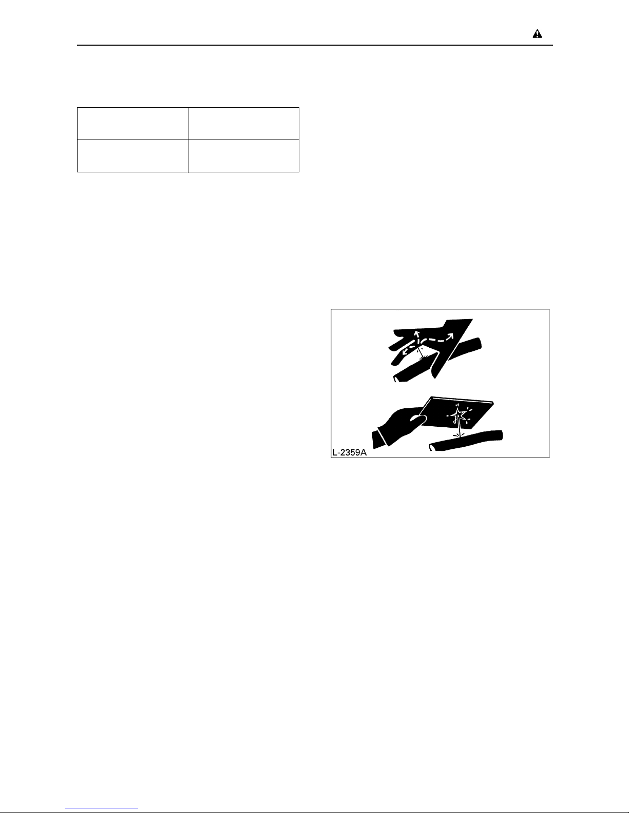
13.Use a face mask or eye protection to protect
the eyes and respiratory system against
dust and other foreign particles.
14.Do not crawl under the excavator if the
excavator is only supported by the boom
and arm or the dozer. The excavator can tip
over or lower itself due to hydraulic pressure
loss. Always use safety struts or other
appropriate supports.
15.KUBOTA uses no parts which are lined with
asbestos. Do not use these kind of parts
even if they can be installed.
16.Fire prevention
Excavator and some attachments have
components that are at high temperatures
under normal operating conditions. The
primary source of high temperatures is the
engine and exhaust system. The electrical
system, if damaged or incorrectly
maintained, can be a source of arcing or
sparks.
The following fire prevention guidelines will
help to keep your equipment up and running
efficiently and keep the risk of fire to a
minimum.
A Blow off all accumulated debris near hot
engine exhaust components such as
turbocharger and exhaust manifold as well
as exhaust pipes and muffler more
frequently when working in severe
conditions.
A Clean out all accumulated flammable debris
such as leaves, straw, pine needles,
branches, bark, small wood chips and any
other combustible materials from inside the
machine belly pans or lower unit structures
as well as from area in proximity to the
engine.
A Inspect all fuel lines and hydraulic hoses for
wear or for deterioration. Replace them
immediately if they begin to leak.
A Examine electrical wiring and connectors
frequently for damage. Repair any wires
that are loose or frayed before operating the
machine. Clean all electrical connections
and tighten all electrical connections as
necessary.
A Inspect the exhaust system daily for any
signs of leakage. Check for broken pipes
and muffler and also for loose or missing
bolts, nuts and clamps. If any exhaust leaks
or fractured parts are found, repairs must be
completed prior to operation.
A Always keep a multipurpose fire
extinguisher on or near the machine. Be
familiar with the operation of the fire
extinguisher.
Page 16
-7SAFE OPERATION
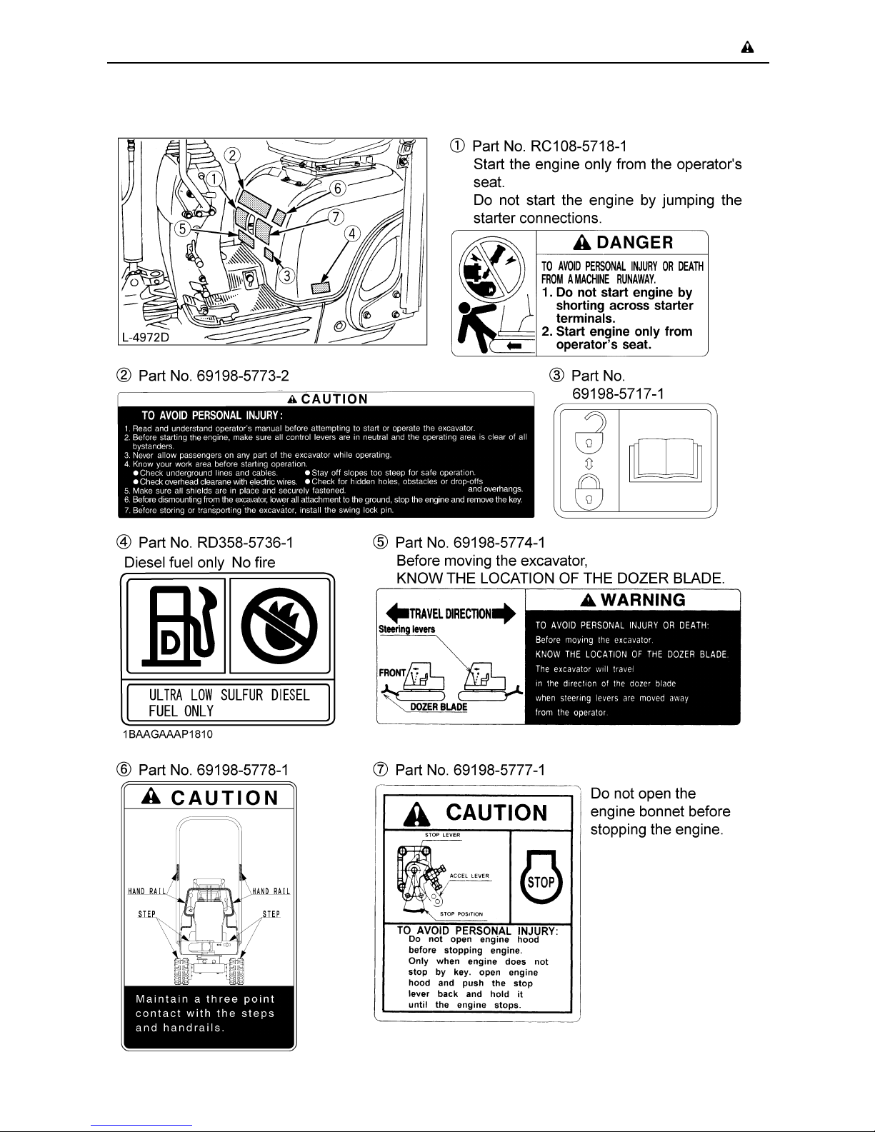
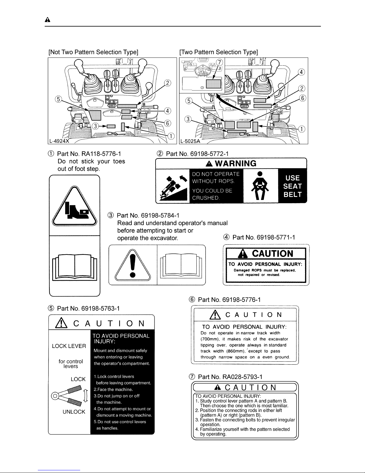
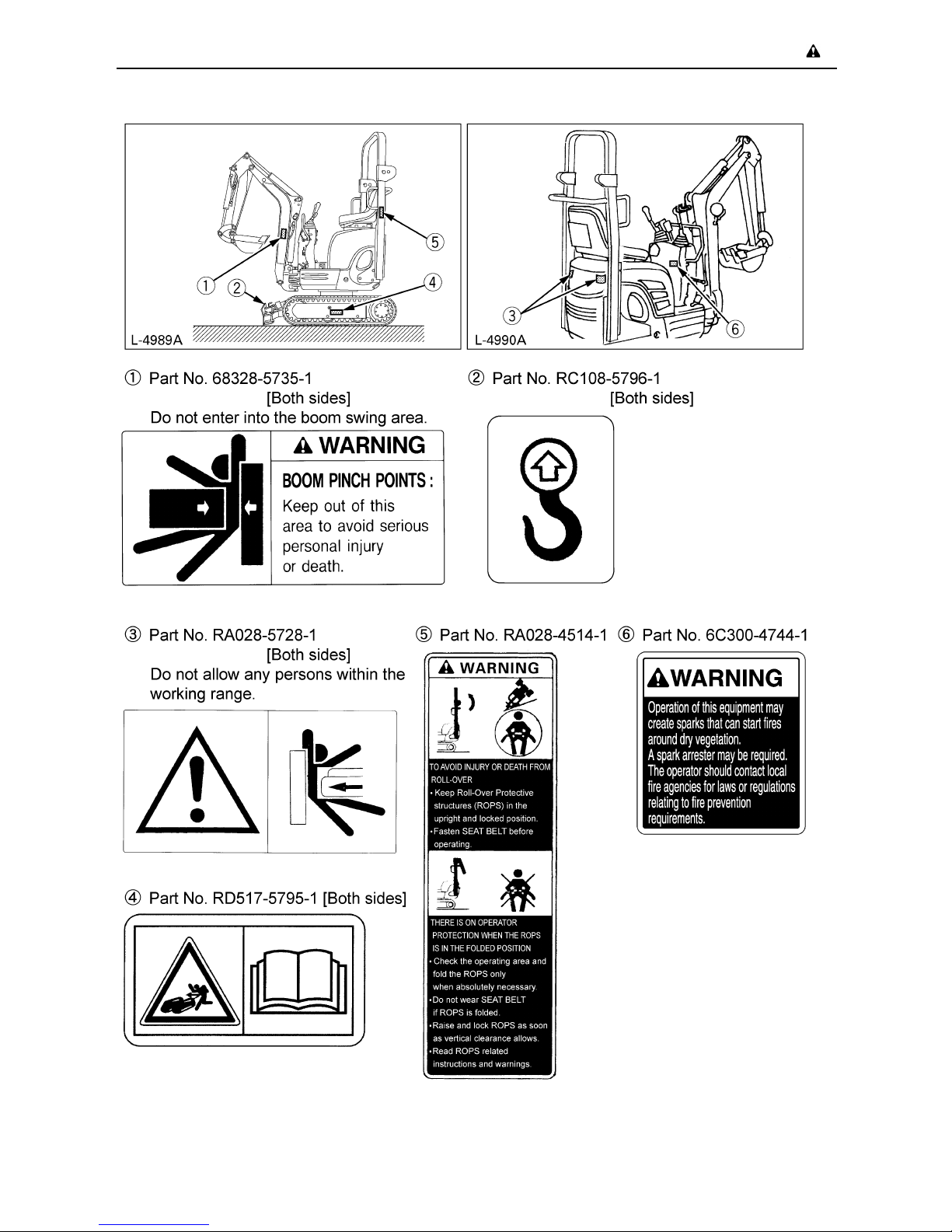
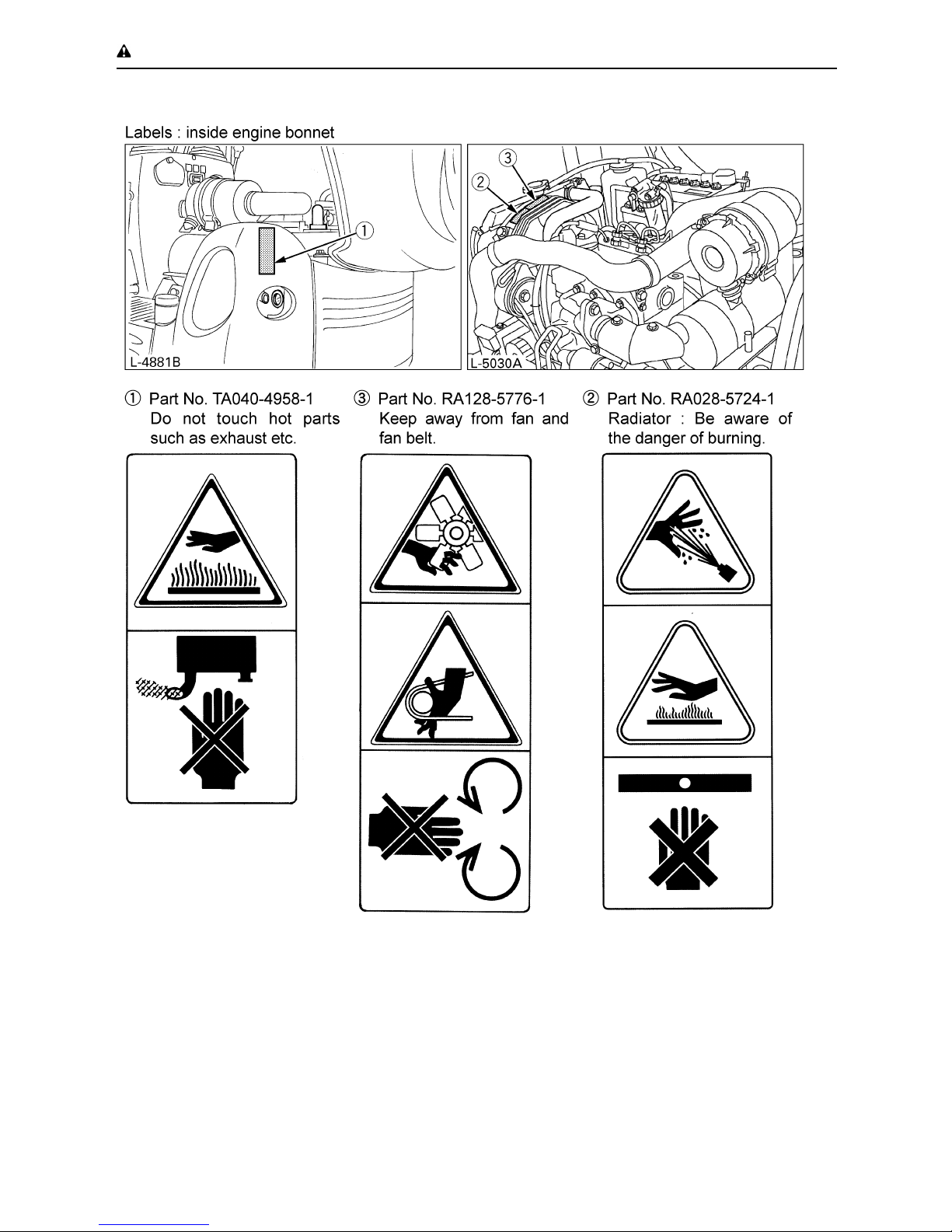
6. DANGER, WARNING AND CAUTION LABELS
Page 17
-8 SAFE OPERATION
Page 18
-9SAFE OPERATION
Page 19
-10 SAFE OPERATION
7. CARE OF DANGER, WARNING AND CAUTION LABELS
(1) Keep danger, warning and caution labels, clean and free from obstructing material.
(2) Clean danger, warning and caution labels with soap and water, dry with a soft cloth.
(3) Replace damaged or missing danger, warning and caution labels with new labels from your
KUBOTA dealer.
(4) If a component with danger, warning and caution label(s) affixed is replaced with new part, make
sure new label(s) is (are) attached in the same location(s) as the replaced component.
(5) Mount new danger, warning and caution labels by applying on a clean dry surface and pressing
any bubbles to outside edge.
Page 20
1DEALER SERVICE
DEALER SERVICE
Your KUBOTA dealer is always ready to help so
that your excavator offers the best performance.
After having carefully read this manual, you will
realize that much of the routine maintenance
can be done by yourself. Your KUBOTA dealer
is responsible for servicing and the delivery of
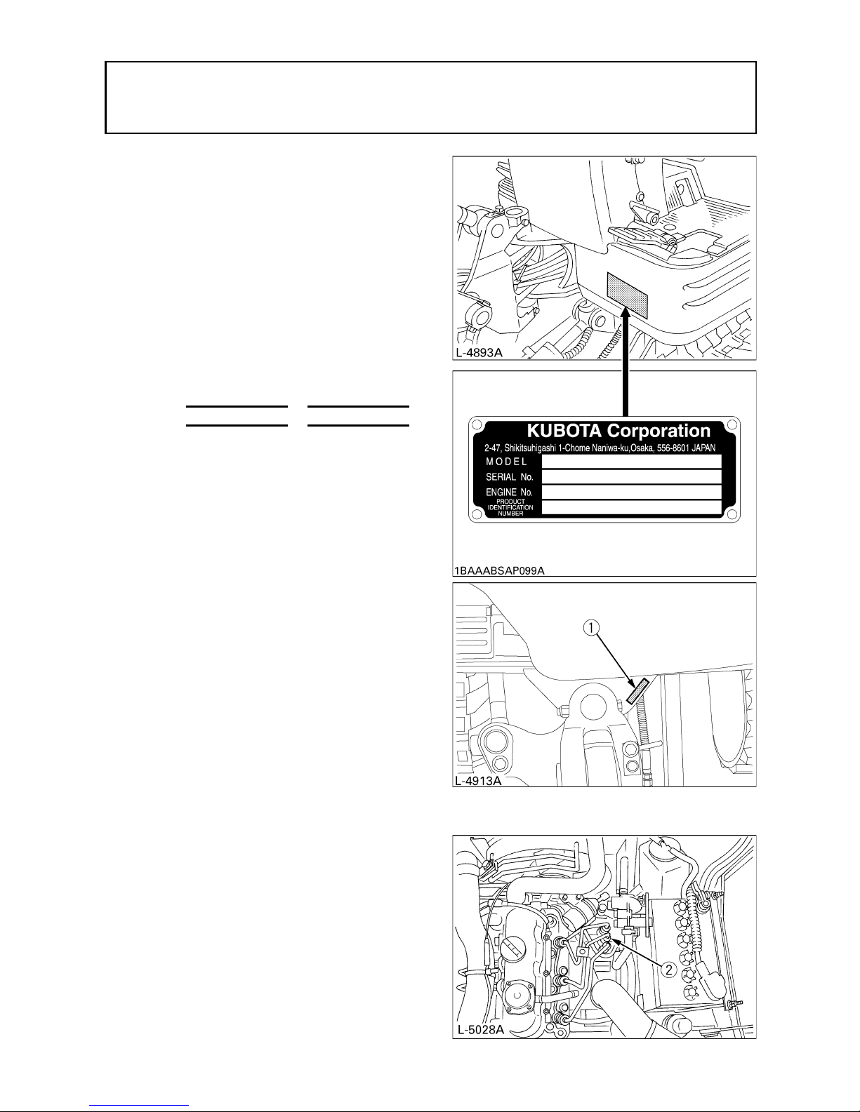
spare parts. When ordering spare parts from
your KUBOTA dealer, always mention the serial
number of the excavator and the engine.
Note these numbers right away in the supplied
lines.
Model Serial No.
Excavator
Engine
Dealer's name
(To be filled in through the owner)
(1) Serial No.
(2) Engine serial No.
Page 21

2 TECHNICAL DATA
TECHNICAL DATA
A Above dimensions are based on the machine with JPN bucket.
JPN = made in Japan
KUBOTA EXCAVATOR
Model name K008-3
Type Rubber tracks
Machine weight lbs (kg) 2028 (920)
Standard bucket
Volume (CECE) cu.in. (m ) 1340 (0.022)
Width in. (mm) 13.8 (350)
Engine
Type Water cooled 3 cylinder Diesel
Model name KUBOTA D722-EBH
Total displacement cu.in. (m ) 44 (719)
Engine power
Gross kW (HP) 7.7 (10.3)
Net kW (HP) 7.5 (10.1)
Rated speed rpm 2050
Low idle speed rpm 1100 to 1300
Performance
Swing speed rpm 8.3
Travel speed mph (km/h) 1.2/2.5 (2.0/4.0)
Ground pressure psi (kgf/cm ) 3.41 (0.24)
Climbing angle % (deg) 27 (15)
Dozer (width & height) ft.in. (mm)
2 ft. 3.6 in. (700) x 7.9 in. (200)
2 ft. 9.9 in. (860) x 7.9 in. (200)
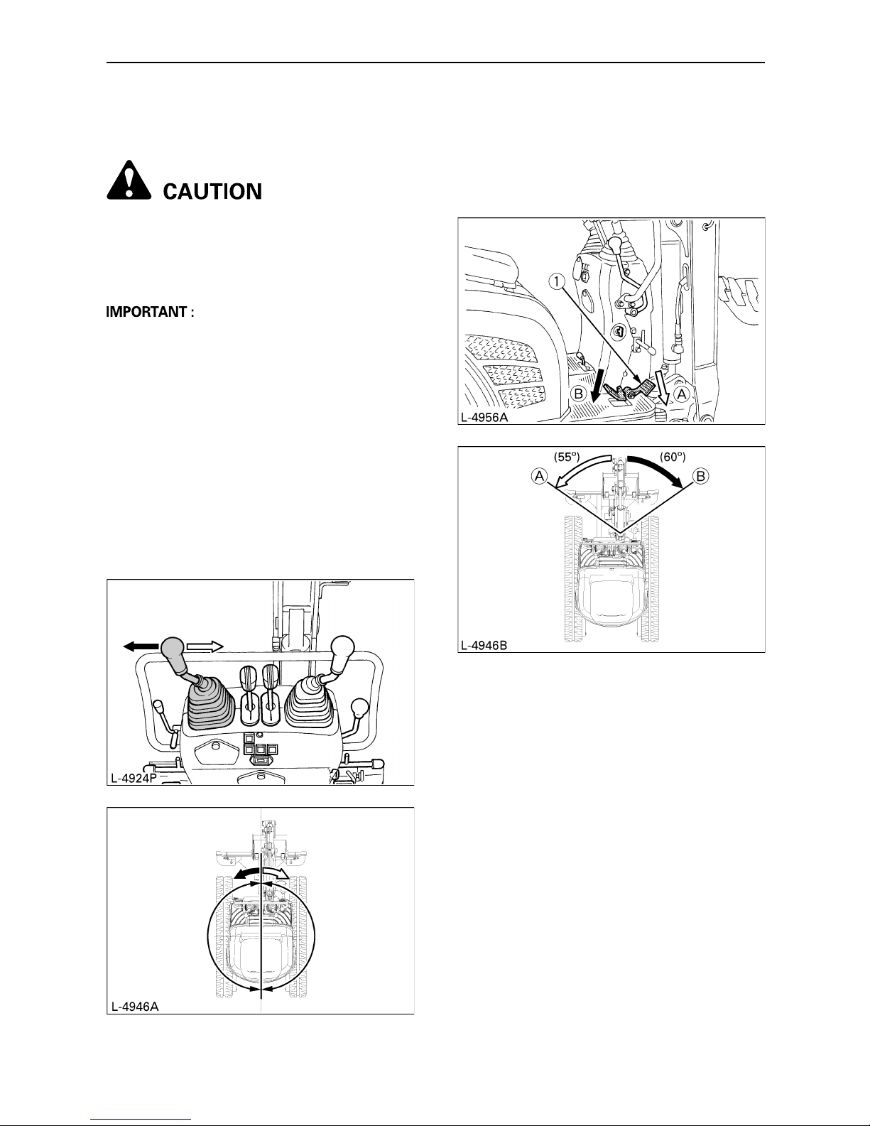
Boom swing angle
Left rad (deg) 0.96 (55)
Right rad (deg) 1.05 (60)
Pressure
connection for
attachments
Dis p lacement GPM (L/m i n ) 5.55 ( 2 1 .0)
Max. pressure psi (kgf/cm ) 2420 (170)
Fuel tank capacity gal (L) 3.2 (12)
Page 22
3DESCRIPTION OF MACHINE PARTS
DESCRIPTION OF MACHINE PARTS
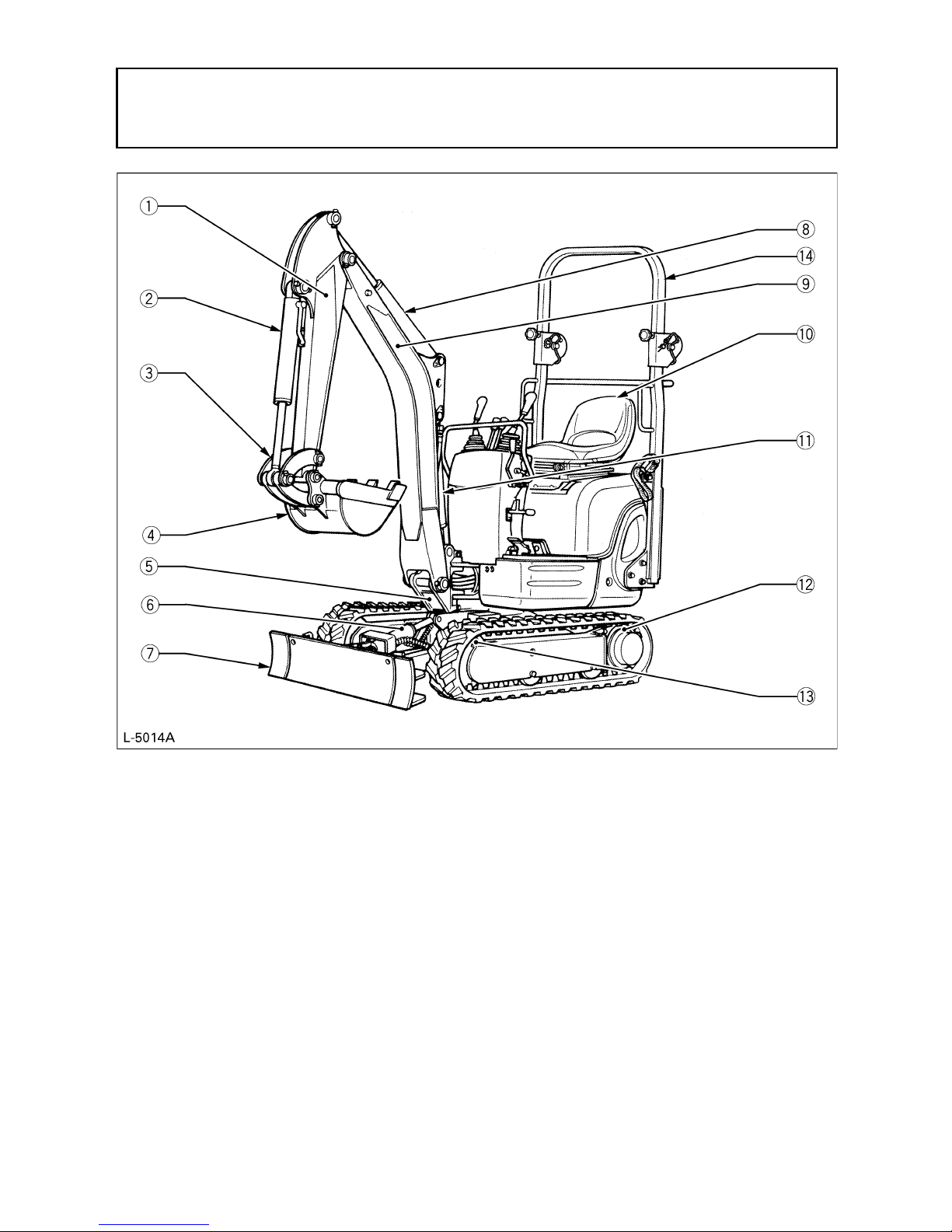
DEPICTED CONTENTS
(1) Arm
(2) Bucket cylinder
(3) Bucket link
(4) Bucket
(5) Swing bracket
(6) Dozer cylinder
(7) Dozer
(8) Arm cylinder
(9) Boom
(10) Operator's seat
(11) Boom cylinder
(12) Drive sprocket
(13) Front idler
(14) ROPS
Page 23
4 INSTRUMENT PANEL AND CONTROL ELEMENTS
INSTRUMENT PANEL AND CONTROL ELEMENTS
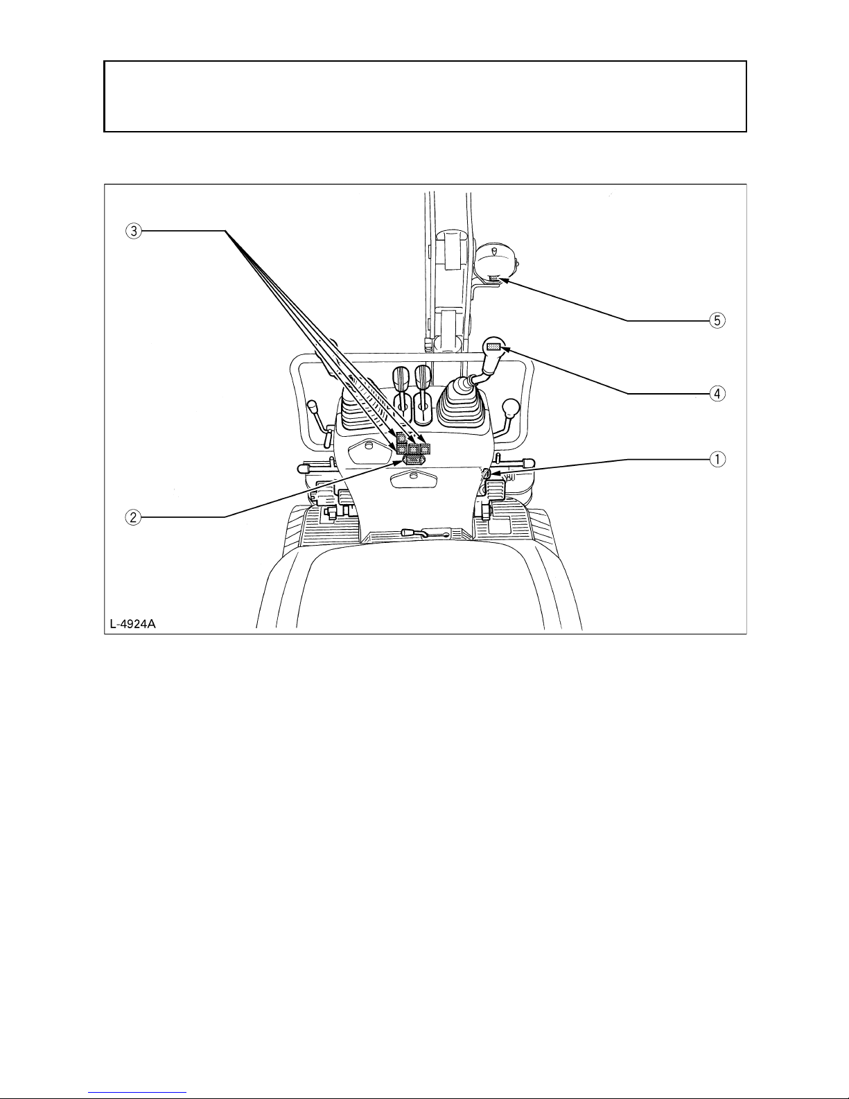
B Instrument Panel, Switches
DEPICTED CONTENTS
(1) Starter switch
(2) Hour meter
(3) Alarm lamp
(4) Horn switch
(5) Working light switch
Page 24
5INSTRUMENT PANEL AND CONTROL ELEMENTS
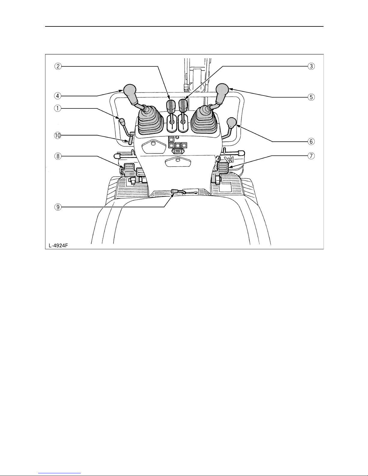
B Control Pedals and Levers
DEPICTED CONTENTS
(1) Throttle lever
(2) Drive lever (left)
(3) Drive lever (right)
(4) Control lever for front attachments (left)
(5) Control lever for front attachments (right)
(6) Control lever for dozer or track width
(7) Swing pedal
(8) Service port pedal
(9) Track width change / dozer select lever
(10) Lock lever
Page 25
6 BEFORE START
BEFORE START
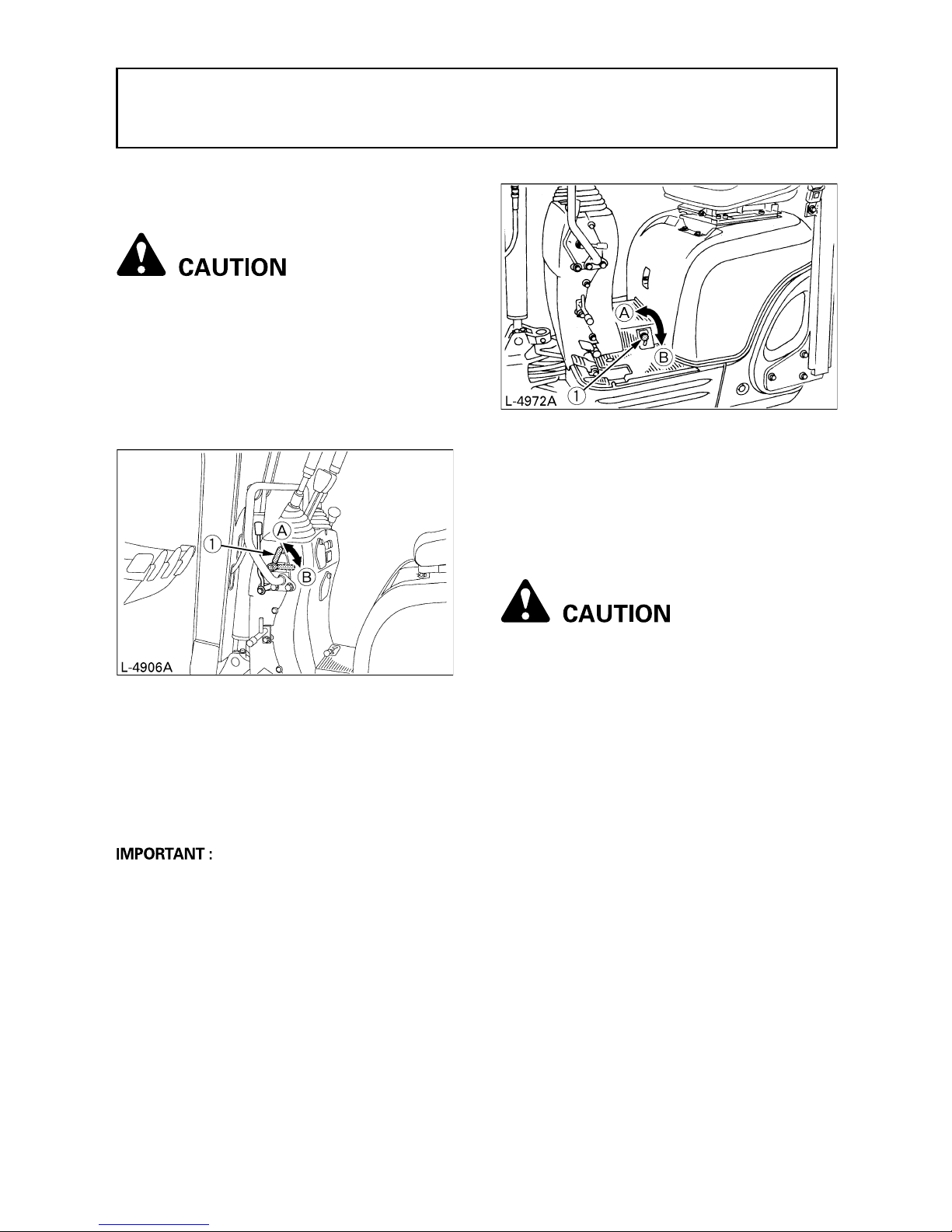
HANDLING THE SAFETY DEVICES
BControl lever lock
A When the excavator is not used or left
unattended, be sure to place the bucket
on the ground and lock the control
levers. The front attachment may fall : it's
dangerous. Also remove the key.
The attachment control lever lock is located on
the left side alike.
BSwing lock pin
This pin is used to lock the swing frame. Set the
lock pin to the "Lock" position and the swing
frame gets locked to the track frame.
A Before locking the lock pin, be sure to place
the swing frame and the track frame parallel
with each other.
DAILY CHECKS
In order to avoid damage, it is important to
check the condition of the excavator before
starting.
To avoid personal injury:
A Do maintenance work on the
excavator only on even ground with
the engine off and the safety devices
in the "Lock" position.
Checks
Walk around the excavator and check for visual
damage and wear.
Check coolant level. (See regular checkpoints
in "MAINTENANCE".)
Check fuel level.
Check engine oil level.
Check hydraulic fluid level.
Check air filter for clogging.
Check all alarm lamps and hour meter.
Check the light system.
Check seat belt and ROPS.
Check the condition of the danger, warning and
caution labels. (See "DANGER, WARNING
AND CAUTION LABELS" in "SAFE
OPERATION" .)
(1) Lock lever (A) "Lock"
(B) "Unlock"
(1) Swing lock pin (A) "Unlock"
(B) "Lock"
Page 26

7OPERATION OF THE ENGINE
OPERATION OF THE ENGINE
To avoid personal injury:
A Read "SAFE OPERATION" at the
beginning of this operator's manual.
A Obey the danger, warning and caution
labels on the excavator.
A Exhaust gases are poisonous. Do not
let the engine run in closed quarters
without sufficient and adequate
ventilation.
A Always start the engine from the
operator's seat. Do not start the
engine while standing next to the
excavator. Before starting the engine,
sound the horn to get the attention of
persons standing nearby.
A Do not use start help spray or similar fluids.
A In order not to overload the battery and
starter, avoid start-ups of more than 10 sec.
A When the engine does not start in 10 sec.,
please set the interval to 20 sec. or more,
and restart.
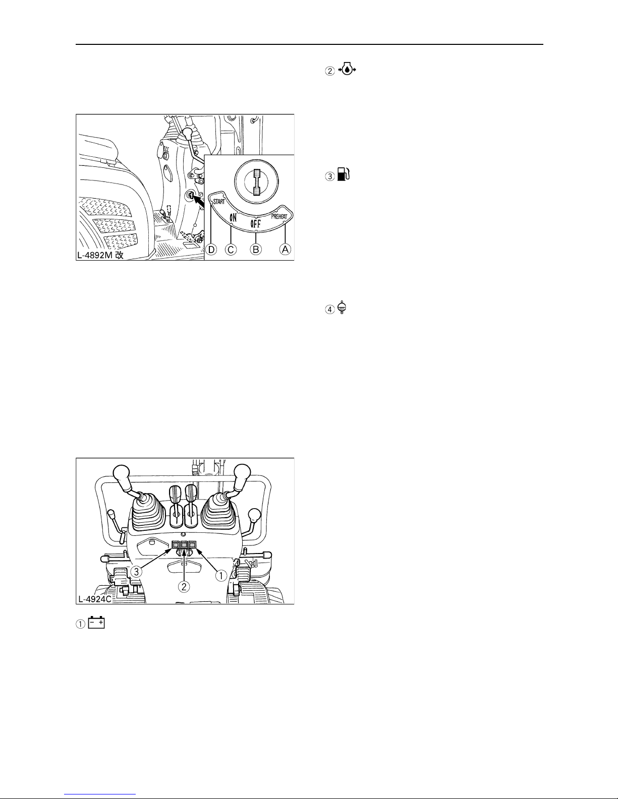
STARTING THE ENGINE
To avoid personal injury:
A The operator should not depend
solely on the alarm lamps, but should
always conduct the routine checks
(see "MAINTENANCE").
Start the engine in the following manner:
1. Make sure that the fuel shutoff-valve is in the
"Open" position.
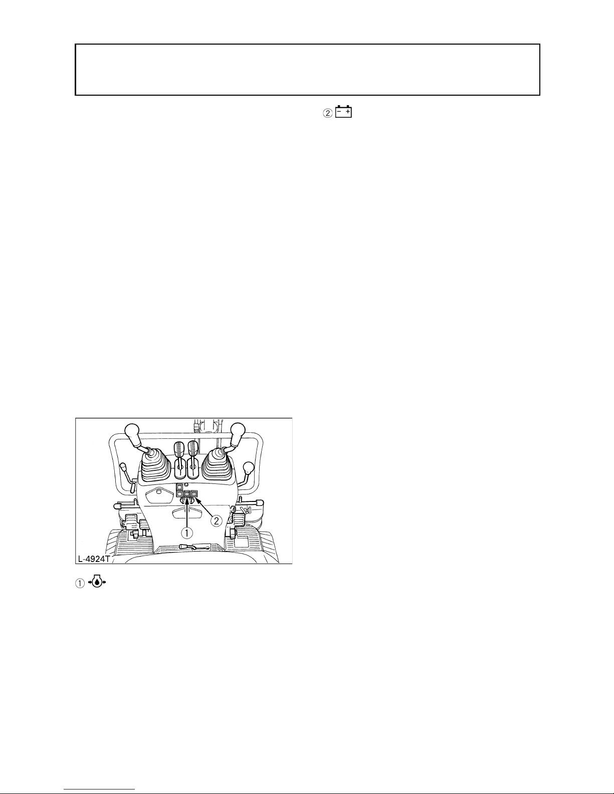
2. Before starting the engine, make sure that
all control levers are in the neutral positions.
(1) Horn switch
(1) Fuel shutoff-valve (A) "Open"
(B) "Closed"
(1) Drive lever (left)
(2) Drive lever (right)
(3) Attachment control lever (left)
(4) Attachment control lever (right)
(5) Throttle lever
(6) Control lever for dozer or track width
Page 27
8 OPERATION OF THE ENGINE
3. Pull the throttle lever all the way back.
4. Insert the key into the starter switch and turn
it to position "ON".
5. Turn the key to position "Preheat".
(approx. 5 seconds)
6. Turn the key to position "Start" and release
after the engine has started; it will
automatically return to the position "ON".
7. Check if all alarm lamps have gone out.
Should an alarm lamp still be lit up, stop the
engine and check for the cause.
Malfunction Indicator (Quick Diagnosis)
Alarm Lamp "Battery Charge"
This lamp lights up when there is a malfunction
in the electrical system. The lamp lights up
when the key is in the "ON" position and goes
out as soon as the engine starts.
Alarm Lamp "Engine Oil Pressure"
This lamp lights up when there is an abnormality
in the engine oil circulation.
It lights up when the key is in the "ON" position
and goes out as soon as the engine starts
running. Should the lamp light up while the
engine is running, check the engine oil level.
Alarm Lamp "Fuel Level too Low"
This lamp lights up when the fuel level in the fuel
tank is lower than 0.58 gal (2 L). The lamp lights
up for three seconds to check the dead lamp
when the key is in the "ON" position while the
engine is stopped.
The lamp goes out when the key is in the
"START" position while the dead lamp check is
lit.
Alarm Lamp
"Water temperature warning"
This lamp lights up if the cooling system gets in
trouble while the engine is running. The lamp
lights up for three seconds to check the dead
lamp when the key is in the "ON" position while
the engine is stopped.
The lamp goes out when the key is in the
"START" position while the dead lamp check is
lit. If the lamp stays on with the engine running,
interrupt the operation and keep the engine at
idling speed for about 5 minutes and then stop
the engine. Now check the following points.
(1) Check for cooling water shortage and
leak.
(2) Check the fan belt for looseness.
(3) See if the radiator is covered with mud
or dirt.
(A) "PREHEAT"
(B) "OFF"
(C) "ON"
(D) "START"
Page 28

9OPERATION OF THE ENGINE
BHourmeter
The hourmeter shows the total operating hours
of the excavator.
C Meter reading
The meter counts up 1 for one operating hour.
The electric meter is still counting if the engine
stops but the key is in the "ON" position.
BCheckpoints after Starting the
Engine
After starting the engine, but before starting
operation, check following points:
1. Put the throttle lever in the "LOW" position
and let the engine idle for approx. 5 minutes.
This allows the engine lubricant to warm up
and penetrate every part of the engine.
A This idling is usually called "Warm-up".
2. Once the engine has warmed up, check:
A the alarm lamp "Engine oil pressure" has
gone out.
A the alarm lamp "Battery charge" goes out
when accelerating the engine.
A the colour of the exhaust gas is normal
and no abnormal noises or vibrations are
heard or felt.
A no fluid is leaking from pipes or hoses.
C Should any following conditions arise,
stop the engine immediately.
A The engine revolution increases or
decreases suddenly.
A Sudden abnormal noises.
A Exhaust gas is black.
A Alarm lamp for engine oil lights up during
operation.
A In these cases, the excavator must be
checked and serviced according to the
directions of the KUBOTA dealer.
STARTING THE ENGINE UNDER
COLD CONDITIONS
To avoid personal injury:
A Make sure that the lock lever is in the
lock position during warm up.
Start the engine in the following manner;
1. Pull the throttle lever completely all the way
back.
2. Turn the key to the "PREHEAT" position.
(approx. 10 sec.)
3. Turn the key to the "START" position; the
engine will start.
4. Release the key after the engine has
started; it will automatically return to the
"ON" position.
A Let the engine warm up after start-up.
A Let the engine warm up after start-up for
approx. 10 minutes under no load
conditions. If the hydraulic fluid temperature
is too low, the operation will be affected.
Do not operate the excavator under full load
before the engine is warmed up enough.
(1) Hourmeter
Page 29
10 OPERATION OF THE ENGINE
STOPPING THE ENGINE
To avoid personal injury or death:
A Do not keep the bucket or dozer in the
lifted position, as a person could
accidentally touch the levers and
cause serious accidents.
A Lower all work attachments on to the
ground, otherwise accidents could
occur.
Let the engine idle for approx. 5 minutes to let it
cool down.
1. Put the throttle lever in idle position.
2. Lower the work attachments carefully on the
ground by activating the levers.
3. To stop the engine, turn the key to the "OFF"
position and remove the key.
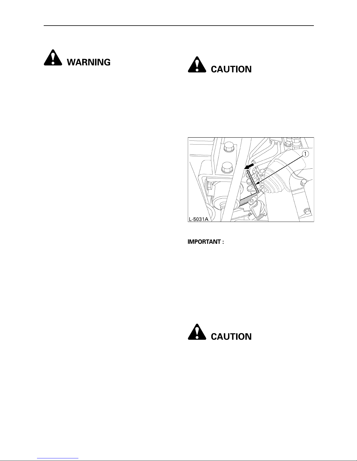
BEngine Stop Lever
To avoid personal injury:
A In the case of an emergency, or
should the engine in idle position and
key in the off position, still run, do like
as below.
Open the engine hood and push the stop lever
back and hold until the engine stops.
A If the throttle lever is not in the idle position,
the engine will continue to turn even if the
key is in the "OFF" position. Make sure that
the throttle lever is in the idle position before
turning the key.
A If the engine does not stop with the key,
contact your KUBOTA dealer.
STARTING WITH AN AUXILIARY
BATTERY
To avoid personal injury:
A Battery gases can explode.
Do not smoke and keep sparks and
flames away .
A Do not start the engine with an
auxiliary battery if excavator battery is
frozen.
A Do not connect the black minus
bridge cable to the minus terminal of
the excavator battery.
(1) Engine stop lever
Page 30
11OPERATION OF THE ENGINE
BObserve Following Guidelines
when Starting with an Auxiliary
Battery.
1. Bring the second machine with the same
battery voltage as near as possible to the
excavator.
THE MACHINES MUST NOT COME IN
CONTACT WITH EACH OTHER.
2. Put the levers and pedals of both vehicles in
the neutral position and the lock lever in the
"Lock" position.
3. Wear eye protection and rubber gloves.
4. Remove the battery caps from both
batteries. (If present)
5. Cover the battery opening with a cloth. Make
sure that the cloth does not touch the battery
terminals.
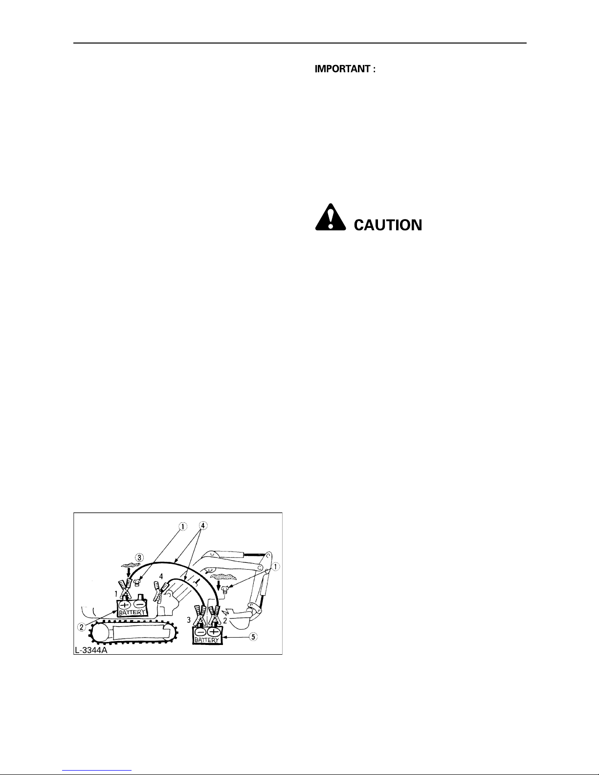
6. Connect the terminal of the red jump lead
with the plus terminal of the empty battery
and connect the other end of the cable to the
plus terminal of the auxiliary battery.
7. Connect the black cable to the minus
terminal of the auxiliary battery.
8. Connect the other end of the black cable
(coming from the auxiliary battery) with the
excavator frame as far away as possible
from the empty battery.
9. Start the engine of the second machine and
let it run for a while. Start the excavator with
the empty battery.
10.Disconnect the jump leads in the opposite
sequence (Steps 8, 7, 6).
11.Remove the cloth and replace the battery
caps.
A This excavator has a negative earthed 12
Volt starting system.
A Only use the same voltage when using an
auxiliary battery.
A Using a higher voltage will cause serious
damage to the electrical system. When
using an auxiliary battery, only the
compatible (same) voltage is permissible.
BPrecautions in case of overheat
To avoid personal injury:
A Do not open the radiator cap during
and just after operation. Hot water
may gush out and get you burned.
Wait long enough until the radiator
cools down.
If by any change cooling water gets heated up
to the boiling point or over (overheated), the
whistle at the reserve tank drain hose end
blows. In such case, take the following steps.
1. Stop operation in a safe condition.
(Disconnect the engine's load.)
2. Do not stop the engine suddenly. Keep the
engine idling under no load for about 5
minutes and turn it off.
3. Keep yourself enough away from the
machine for another 10 minutes or while
steam is given off.
4. Make sure there is no hazard of getting
burned. Pinpoint and remove the cause of
overheat, referring to
"TROUBLESHOOTING". Then get the
engine restarted.
(1) Remove battery caps (if present)
(2) Empty battery
(3) Put a cloth over the battery openings
(4) Jump leads
(5) Auxiliary battery
Page 31
12 EXCAVATOR OPERATION
EXCAVATOR OPERATION
CONTROL OBSERVATIONS
DURING OPERATION
BStop the Engine immediately if:
A Sudden increase or decrease in engine
revolution occurs.
A Sudden abnormal noises occur.
A Exhaust gases turn suddenly very dark.
Make following control observations during
operation to be sure that everything functions
normally.
BAlarm Lamps
Should an alarm lamp light up during operation,
stop the engine immediately and as described
below, check for the cause. Do not use the
excavator when an alarm lamp is lit up.
Explanation of alarm lamp is described as
"Malfunction Indicator (Quick Diagnosis)" under
"STARTING THE ENGINE" in "OPERATION
OF THE ENGINE".
Engine Oil Pressure
When the engine oil pressure sinks below the
prescribed level, the alarm lamp will light up.
Should this occur during operation and not go
out even if the engine revolution is increased by
1000 rpm, check the engine oil level. (see
"Check Engine Oil Level" under "DAILY
CHECKS" in "MAINTENANCE").
Battery Charge
If the battery is not charged by the generator,
the alarm lamp will light up. Should this occur
during operation, check the electrical system or
contact your KUBOTA dealer.
(see "TROUBLESHOOTING")
RUNNING-IN OF THE NEW
EXCAVATOR
The operation and care of the new excavator
influences its life span. Your new excavator has
been carefully checked and tested before
leaving the factory. In spite of this, all movable
components must run-in during the first 50
work hours. Do not work with full revolution and
full loads during this period. It is most important
to run-in your excavator properly in order to
achieve its full performance and longevity.
During the running-in, the following points
should be adhered to in all cases.
BDo not Work with Full Revolutions
or Full Loads during the First 50
Working Hours.
A Let the engine warm up sufficiently in the
cold season.
A Do not let the engine rev-up more than
necessary.
BOil Change in the Run-in Stage.
The lubrication oil plays a specially important
role during the run-in phase of the excavator.
The numerous movable parts are not yet run-in,
so that many fine metal particles can develop
and cause damage or shorten the lifetime of
many components. Pay attention to the oilchange intervals and execute them sooner
rather than later as necessary. See the subject
"Care and Maintenance" for more details on the
oil-change intervals.
Page 32
13EXCAVATOR OPERATION
STARTING
To avoid personal injury:
A No persons, other than those familiar
with the excavator, are allowed to use
the excavator.
A Do not allow any person other than
the operator to ride on the excavator.
BSeat Belt and Adjusting the
Operator's Seat
To avoid personal injury or death:
A Always use the seat belt if a ROPS
protection construction is built in.
Adjust the seat to the optimal position
and buckle up.
1. Adjusting the Operator's Seat
To avoid personal injury:
A Before adjusting the operator's seat,
make sure that no one puts hands on
the engine bonnet behind the seat.
A After having adjusted the seat, make
sure that the seat adjuster has clicked
into position.
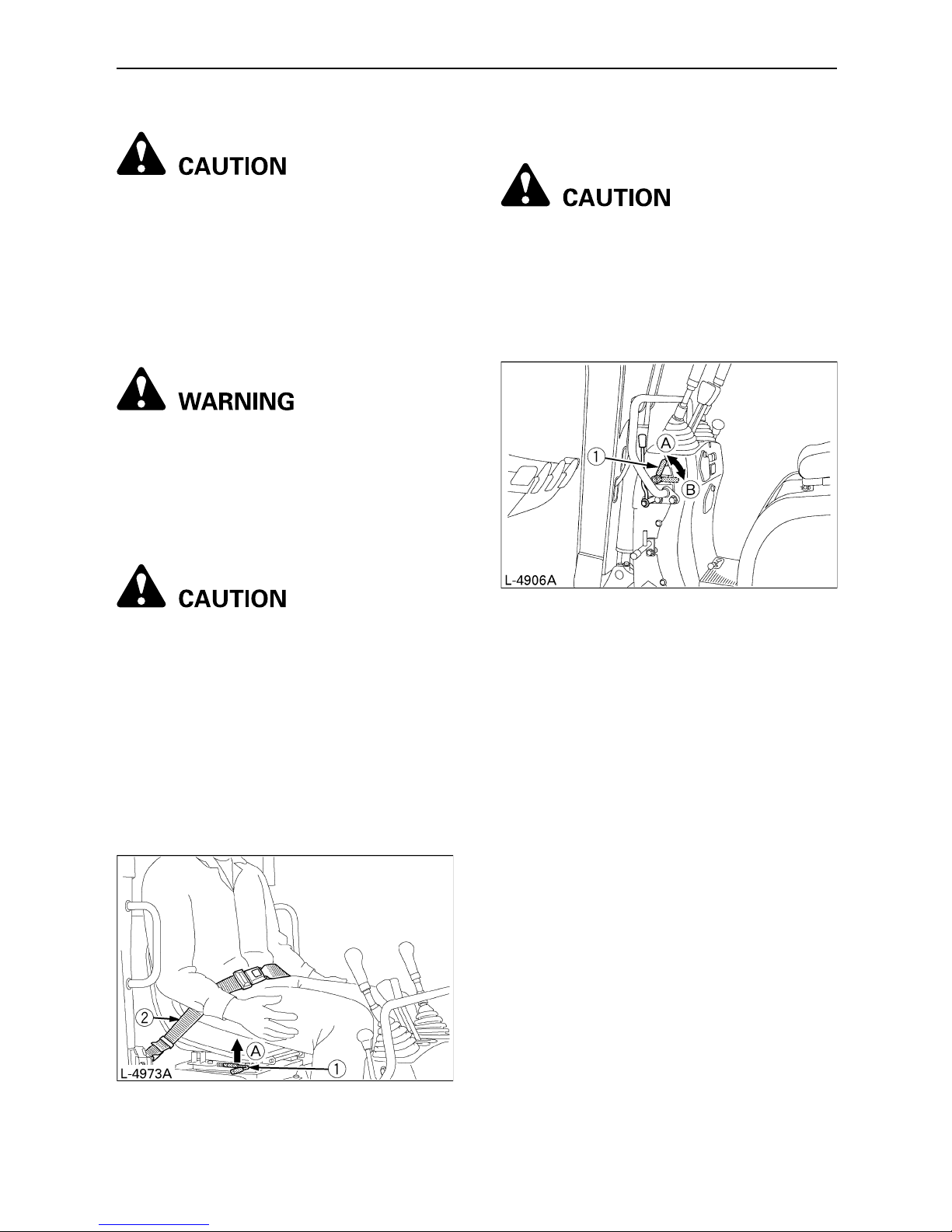
2. Bring the lock lever into the
"Unlock" position.
To avoid personal injury:
A Check safety aspects all around the
excavator.
Please bring the lock lever into the "Unlock"
position, and raise the lower side of the bucket
from the ground by 7.9 to 15.6 in. (20 to 40 cm).
To and fro : While holding up the to-and-fro
adjustment lever, reposition the
seat to and fro.
(1) To-and-fro adjustment
lever
(2) Seat belt
(A) "Hold up"
(1) Lock lever (A) "Lock"
(B) "Unlock"
Page 33
14 EXCAVATOR OPERATION
BWorking Light Switch
If the key is in the "ON" position, the lights will
be switched on by tipping the switch.
C Night operation
To avoid personal injury:
A Visibility is reduced in darkness, so
that the working light alone is not
enough. Prepare additional lighting,
observe safety rules as well as special
regulations for night work.
CONTROLS FOR ATTACHMENTS
The levers move the boom, arm and bucket as
well as the swing frame. The lever positions
and functions are as follows:
[NOT TWO PATTERN SELECTION TYPE]
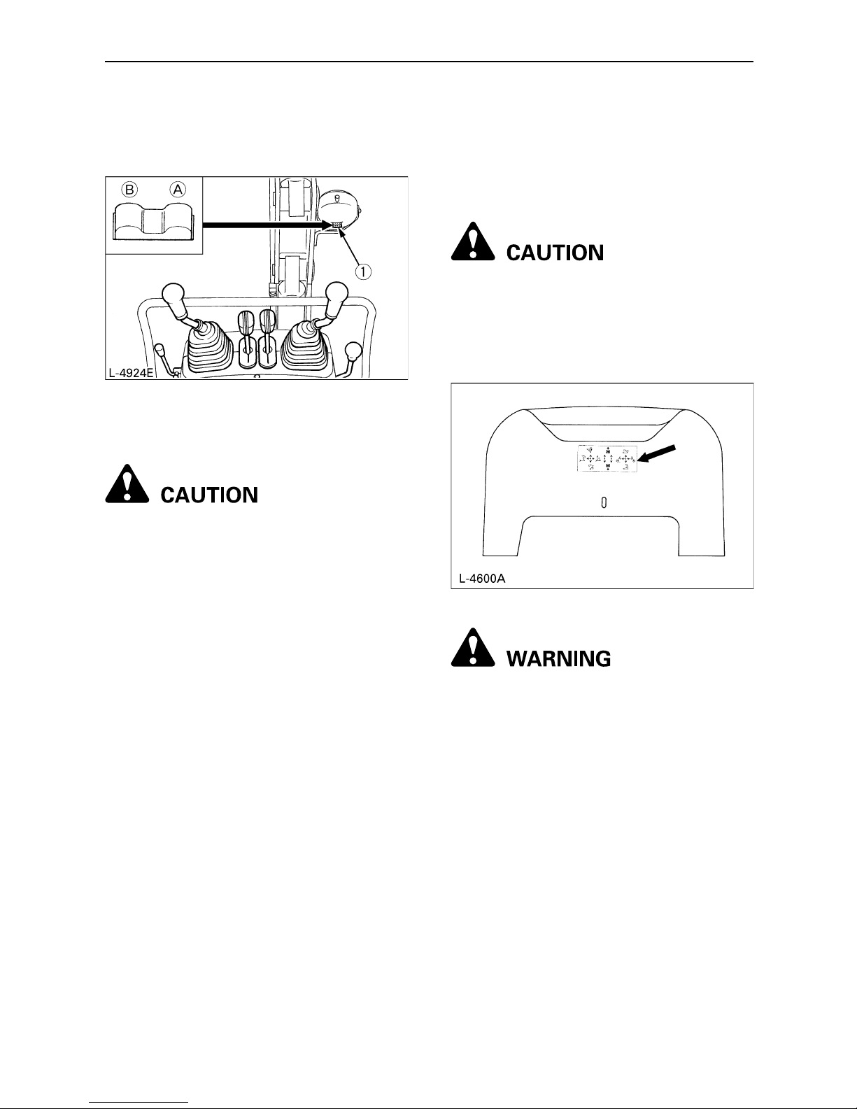
To avoid personal injury:
A Study and familiarize control lever
functions by operating slowly.
A Be sure to check the operating pattern
in the label on the front hood before
operating the excavator.
[TWO PATTERN SELECTION TYPE]
To avoid personal injury or death:
A The control lever pattern on this
machine is changeable. Before
operation, check the current pattern.
Otherwise the machine may get in
trouble or you may get injured.
A Before changing the control lever
pattern, be sure to stop the engine.
A Before operation, be sure to look
around for safety. Move the levers
slowly.
A Make sure the control lever pattern
has been changed as specified.
(1) Working light switch (A) "ON
(B) "OFF"
Page 34

15EXCAVATOR OPERATION
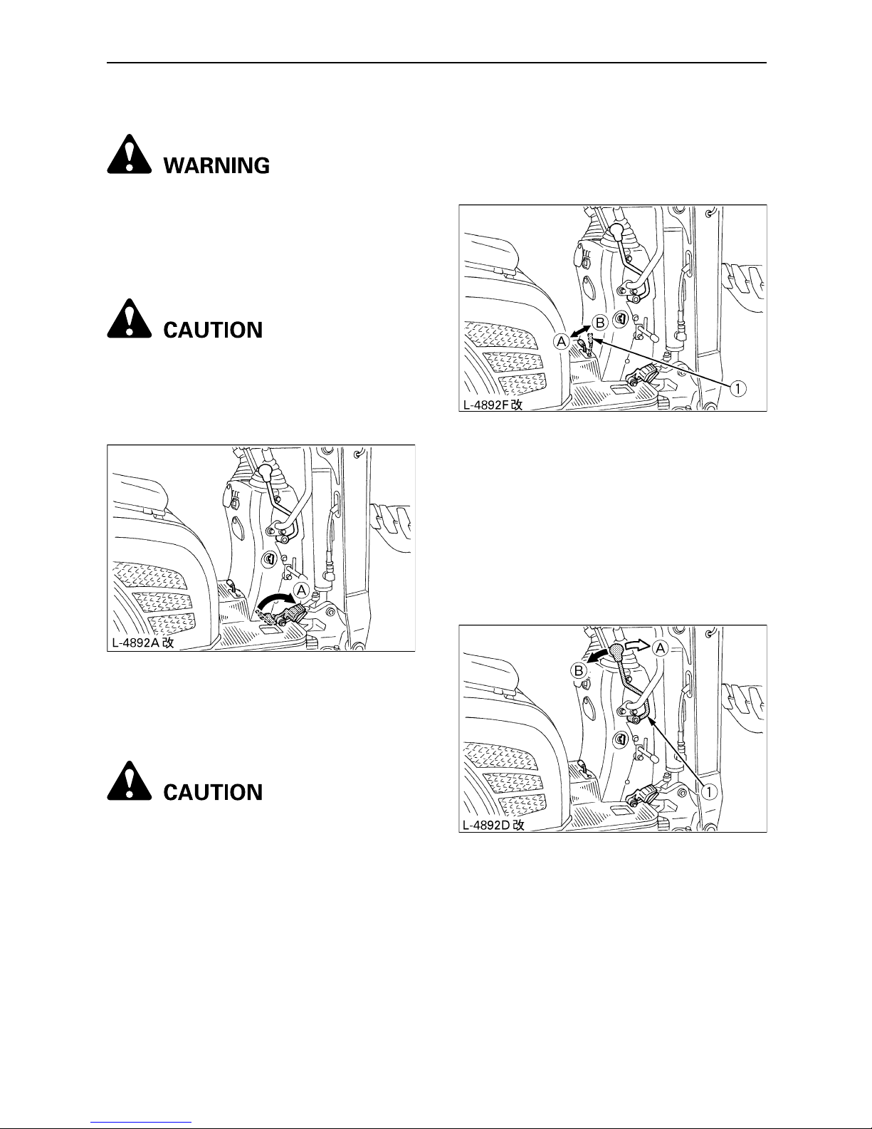
C Pattern Change
Switching from [Pattern A] to [Pattern B]
1. Stop the engine and place the front
attachment on the ground. Release
pressure out of the cylinders.
2. Turn the knob on the control box to open the
cover.
3. Remove the bolts (1) and (2).
4. Shift the joints (C) and (D) to the right, and
apply and tighten up the bolts (1) and (2).
To avoid personal injury:
A The bolts (1) and (2) are of special
type. Do not use general bolts,
because otherwise the machine may
malfunction and get damaged.
(1) Knob
(1) Bolt1
(2) Bolt2
(3) Joint (C)
(4) Joint (D)
(1) Bolt1
(2) Bolt2
(3) Joint (C)
(4) Joint (D)
Page 35

16 EXCAVATOR OPERATION
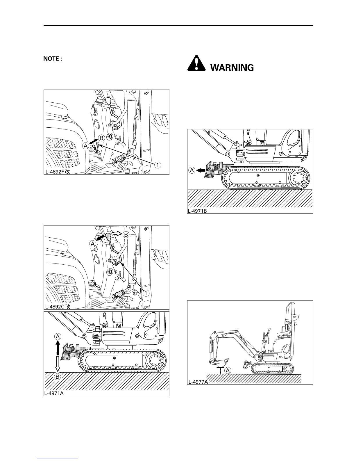
C Switching from [Pattern B] to [Pattern A]
1. Stop the engine and place the front
attachment on the ground. Release
pressure out of the cylinders.
2. Turn the knob on the control box to open the
cover.
3. Remove the bolts (1) and (2).
4. Shift the joints (C) and (D) to the left, and
apply and tighten up the bolts (1) and (2).
To avoid personal injury:
A The bolts (1) and (2) are of special
type. Do not use general bolts,
because otherwise the machine may
malfunction and get damaged.
(1) Knob
(1) Bolt1
(2) Bolt2
(3) Joint (C)
(4) Joint (D)
(1) Bolt1
(2) Bolt2
(3) Joint (C)
(4) Joint (D)
Page 36

17EXCAVATOR OPERATION
*NOTE:
A See "SWIVEL MOVEMENT AND SWING
MOVEMENT".
OPERATION OF THE BOOM
To raise the boom, pull the attachment control
lever back.
The boom is equipped with a cushion cylinder
which prevents excavated material in the bucket
from fall-in out. By low hydraulic oil temperature,
(e.g. right after starting the engine) the
cushioning function will only be effected after a
certain delay (approx. 3 to 5 seconds). This
condition results from the viscosity of the
hydraulic oil and is no sign of a malfunction.
A When lowering the boom, make sure that it
does not hit the dozer and that the bucket
teeth do not touch the dozer.
Lever position
Movement
Pattern A
(JD)
Pattern B
(ISO)
Left Front
Attachment
Control Lever
ABoom lower Arm out
B Boom raise Arm in
*C Swivel to left Swivel to left
*D Swivel to right Swivel to right
Right Front
Attachment
Control Lever
1 Arm out Boom lower
2 Arm in Boom raise
3 Bucket dig Bucket dig
4 Bucket dump Bucket dump
Page 37

18 EXCAVATOR OPERATION
OPERATION OF THE ARM
Pull back the left attachment control lever and
the arm will be pulled in. To move the arm out,
push the control lever towards the front.
A When pulling in the arm, the movement may
stop for a short moment when the arm is in
its vertical position. This is caused by the
fact that at this position the maximum load
for the arm and bucket is reached, and the
hydraulic pressure in the cylinder is not high
enough. This is a characteristic of the
hydraulic system and is not a sign of a
malfunction.
OPERATION OF BUCKET
To dig with the bucket, move the right
attachment control lever from the neutral
position towards the left. Moving the control
lever towards the right pushes the bucket
outwards and dumps its contents.
Page 38
19EXCAVATOR OPERATION
SWIVEL (UNIT SWING)
OPERATION
To avoid personal injury:
A When working in groups, always let
the others know what you are going to
do before you do it.
A Keep away from the working area.
A Do not operate the left attachment
control lever abruptly from the right to
the left (or vice versa). Because of the law
of inertia, this causes an impact load on
the swing gear and the swing motor.
Additionally, the lifetime of the excavator
will be shortened.
A Unlock the swing lock pin before
carrying out swivel operations.
1. Tilt the control lever to the left and the upper
structure will turn to the left.
2. Tilt the control lever to the right and the
upper structure will turn to the right.
BOOM SWING OPERATION
1. Step on the front of the pedal to swing the
boom to the left.
2. Step on the rear of the pedal to swing the
boom to the right.
(1) Boom swing pedal (A) Swing to left
(B) Swing to right
Page 39
20 EXCAVATOR OPERATION
BOOM SWING PEDAL
To avoid personal injury or death:
A Always keep your toes within the
edge of foot step; otherwise there is a
possibility that your toes will be
caught between swing frame and
boom or boom cylinder.
To avoid personal injury:
A When boom swing operation is not in
use, fold the boom swing pedal
forward to fix the pedal from
unexpected moves.
OPERATION OF TRACK WIDTH
CHANGE AND DOZER
To avoid personal injury:
A Do not operate in narrow track width
[2ft. 3.6in. (700mm)], there is a risk of
the excavator tipping over, always
operate in standard track width [2ft.
9.9in. (860mm)], except when passing
through narrow spaces on a even
ground.
A For changing the track width or using
the dozer, set the track width change/
dozer select lever fully.
If not, the excavator may
unintentionally move.
BOperation of the Track Width
1. Set the track width change/dozer select
lever to the "Track width change" position
(B).
2. Push the control lever forward.
... The track width reduces
[from 2ft. 9.9in. to 2ft. 3.6in.
(from 860mm to 700mm)].
Pull the control lever backward.
... The track width increases
[from 2ft. 3.6in. to 2ft. 9.9in.
(from 700mm to 860mm)].
(A) "Fix"
(1) Track width change /
dozer select lever
(A)"Dozer"
(B)"Track width change"
(1) Control lever (A) "Reduce"
(B) "Increase"
Page 40

21EXCAVATOR OPERATION
3. After track width change, be sure to set the
track width change/dozer select lever to the
"Dozer" position (A).
BOperation of the Dozer Width
For changing from standard width to narrow
width:
1. Pull out the fixing pin (2) and remove the
extension dozer (1).
2. Set the extension dozer (1), insert fixing pin
(2) as illustration.
3. It is the same operations for opposite side
(left or right), and also for changing from
narrow width to standard width.
(1) Extension dozer
(2) Fixing pin
Page 41
22 EXCAVATOR OPERATION
BOperation of the Dozer
A While operating the dozer, the track width
change / dozer select lever must be set
position (A).
1. To raise the dozer, pull back the control
lever. Pushing the control lever forwards,
lowers the dozer.
2. While undertaking earth moving work,
control both drive levers with the left hand
and the control lever with the right hand.
DRIVING
To avoid personal injury or death:
A Before starting the engine, make sure
that no further persons are in the
excavator surroundings.
A Before operating the excavator, check
the crawler direction. (Idler and dozer
to the front of the excavator).
A Avoid travelling across a slope or
working sideways on a slope.
1. To lock the swing frame with the track frame,
engage the swing lock pin.
2. Adjust the engine speed from idling to an
intermediate speed.
3. Raise the dozer and hold the bucket about
7.9 to 15.6 in. (20 to 40 cm) off the ground.
(1) Track width change /
dozer select lever
(A) "Dozer"
(B) "Track width change"
(1) Control lever (A) "Raise"
(B) "Lower
(A) "Front"
(A) 7.9 to 15.6 in. (20 to 40 cm)
Page 42

23EXCAVATOR OPERATION
BDrive Levers (Right, Left)
To avoid personal injury or death:
A If the swing frame has been turned
180 , i.e. the dozer is, seen by the
operator, "behind", then the travel
direction is opposite to the drive
direction of the levers (when
activating the drive lever forwards,
the excavator, seen by the operator,
will move backwards).
Pushing the drive lever forward, moves the
excavator forward, and vice-versa. The front of
the excavator is the direction where the dozer is
present.
A If the crawler is clogged with sand or gravel
while working on soft ground, lift up one
crawler with the help of the boom, arm and
bucket and let the crawler rotate to shake off
the sand and gravel.
TURNS
To avoid personal injury:
A Do not change direction on steep
slopes, or the excavator could tip
over.
A Before changing direction, beware of
persons in the working area.
BPivot Turn
A Movement as illustrated shows turning
motion with the dozer positioned facing the
front.
When the dozer is facing the back, the turning
direction is reversed.
(For example, push the left (right) drive lever
forward; right (left) crawler, seen by the
operator, will move backward from the
operator.)
(1) Drive lever (left)
(2) Drive lever (right)
(A) "Forward"
(B) "Backward
(A) "Forward"
(B) "Backward
(A) "Rotate to shake off
sand and gravel"
Page 43

24 EXCAVATOR OPERATION
C Change of Direction while Stationary
1. Push the left drive lever forward; the
excavator will turn to the right.
2. Pull the left drive lever backward; the
excavator will turn to the left.
C Change of Direction while Travelling
1. While travelling forwards, bring the left drive
lever in the neutral position; the excavator
will turn to the left.
2. While travelling backwards, bring the left
drive lever in the neutral position; the
excavator will turn to the right.
(A) "Travelling forward"
(C) "Neutral position"
(B) "Travelling backward"
(C) "Neutral position"
Page 44

25EXCAVATOR OPERATION
BSpin Turn
When both drive levers are activated in the
opposite directions, both crawlers will rotate
with the same speed but in opposite directions.
Centre of rotation is the centre of the excavator.
UP AND DOWNHILL TRAVELLING
To avoid personal injury:
A Before travelling up and downhill, be
sure to be in standard track width 2ft.
9.9in. (860mm).
A When travelling up or down a slope
for long periods of time, be sure to
engage the swing lock pin. Also
engage the swing lock pin when
standing on a slope for a long time or
whilst the excavator is being
transported.
While travelling uphill, keep the lower edge of
the bucket approx. 7.9 to 15.6in. (20 to 40cm)
above the ground. Although the KUBOTA
excavator will not slip easily because of the
crawlers, it is safer to let the bucket slide over
the ground while travelling downhill. Always
choose slow speed for uphill and downhill
travelling.
[UPHILL TRAVELLING]
[DOWNHILL TRAVELLING]
(A) "Left spin turn"
(B) "Right spin turn"
(A) 7.9 to 15.6in. (20 to 40cm)
Page 45

26 EXCAVATOR OPERATION
PARKING ON A SLOPE
To avoid personal injury or death:
A When the excavator is parked or left
unattended on a slope, be sure to put
the bucket on the ground and place all
control levers in neutral position, then
brace the crawlers with chocks.
DRIVE SPEED PEDAL
To avoid personal injury:
A If the travel resistance is high as in
running uphill or on an uneven
ground, do not use the drive speed
pedal.
Operate the travel lever, step on the drive speed
pedal, and the vehicle speed will increase.
Release the pedal, and the machine will get
from the acceleration mode back to the normal
speed.
SERVICE PORT OPERATION
This pedal is used to operate attachments such
as breakers.
C Service port pedal
Step on the service port pedal and pressured oil
starts flowing through the "P" port from the
control valve. The oil then returns through the
"T" port into the tank.
A When the service port is not use, put the
cover on the pedal. The pedal gets fixed and
can be used as footrest.
(1) Chock
(1) Drive speed pedal (A) "To increase
speed push down"
(1) Service port pedal (A) "Operate"
(1) "P" (Pressure) port
(2) "T" (Return) port
Page 46

27EXCAVATOR OPERATION
C Locking the service port pedal
The service port pedal can be locked downward
in order to use an attachment such as hand
breaker and hand auger. Please make a hole to
pass the bolt through the floor mat with a knife
etc. when you lock the service port pedal. The
bolt which fixes the pedal is in the tool kit.
Please tighten the bolt until you are able to
depress the service port pedal.
A When the service port is not being used, be
careful not to lock the pedal.
Because the hydraulic oil temperature will
rise abnormally, causing problems with the
hydraulic components.
IMPORTANT INFORMATION ON
EXCAVATOR OPERATION
To avoid personal injury:
A After work, clean the machine and
lubricate all movable parts.
A Check oil level.
A Do not try to crush concrete or boulders
using side swings with the bucket. Also
avoid using side sweeps of the bucket to
move earth piles.
A Under all circumstances avoid the following
operations:
A Excavation using the gravitational impact
of the machine.
A Compacting of gravel or soil using the
dropping action of the bucket.
A Excavation using the travelling power of
the machine.
A Do not try to drop or shake of soil adhering
to the bucket in the manner shown in the
explanation below. This can cause damage
to the machine.
Adhering soil can be shaken off when the
bucket is being emptied by moving the
bucket out to the maximum stroke of the
cylinder. Should this not suffice, swing out
the arm as far as possible and operate the
bucket back and forth.
A Do not hit the dozer with the boom cylinder!
Make sure that the boom cylinder does not
hit the dozer when carrying out deep
excavation. If necessary swivel the upper
structure so that the dozer is at the back of
the machine.
A Pay attention when pulling in the bucket!
When pulling in the bucket (for driving or
transportation) avoid hitting the dozer.
A Avoid collisions!
When moving the excavator, pay attention
so that the dozer does not collide with
obstructions such as boulders etc..
Such collisions substantially shorten the life
span of the dozer and the cylinder.
A Support the machine correctly!
When stabilizing the machine with the dozer,
Iower the whole dozer fully on to the ground.
A If the water or mud level reaches higher than
the top of the tracks, the swivel bearing,
swivel motor gear and ring gear may be
exposed to mud, water and other foreign
objects.
The excavator must be properly pressure
washed after each use.
A Thoroughly clean the area around the
swivel bearing, swivel motor gear and
ring gear to remove foreign objects.
A Inspect the swivel motor oil sump (if
equipped) for water contamination. If
water is present, refer to operator's
manual for lubricant replacement
procedure.
A Refer to operator's manual for proper
swivel bearing, swivel motor gear and
ring gear lubrication procedures.
A Reinstall any protective covering if
removed earlier.
(1) Service port pedal
(2) Bolt
Page 47

28 EXCAVATOR OPERATION
OPERATING FOLDABLE ROPS
To avoid personal injury:
A When raising or folding the ROPS,
stop the engine and remove the key.
Always perform function from a stable
position at the rear of excavator.
A Fold the ROPS down only when
absolutely necessary and fold it up
and lock it again as soon as possible.
BTo Fold the ROPS
1. Loosen both looseness preventing knob
bolts.
2. Remove both set pins.
3. Fold the ROPS.
To avoid personal injury:
A Hold the ROPS tightly with both
hands and fold the ROPS slowly and
carefully.
4. Align set pin holes and insert both set pins.
Slightly tighten the set pins and secure them
with the hair pin cotters.
(1) Set pin
(2) Looseness preventing knob bolt
(1) ROPS
(1) Set pin
(2) Hair pin cotter
Page 48

29EXCAVATOR OPERATION
BTo Raise the ROPS to Upright
Position
1. Remove both hair pin cotters and set pin.
2. Raise ROPS to the upright position.
To avoid personal injury:
A Raise the ROPS slowly and carefully.
3. Align set pin holes, insert both set pins.
Secure them with the hair pin cotters.
4. Tighten both looseness preventing knob
bolts.
To avoid personal injury:
A Make sure that both set pins are
properly installed as soon as the
ROPS is in the upright position and
secured with the hair pin cotters.
BAdjustment of Foldable ROPS
A Adjust free fall of the ROPS upper frame
regularly.
A If you feel less friction in folding the ROPS,
tighten the self locking nut q until you feel the
right friction in the movement.
(1) Set pin
(2) Hair pin cotter
(1) Set pin
(2) Hair pin cotter
(3) Looseness preventing knob bolt
(1) Self locking nut
Page 49

30 TRANSPORTING THE EXCAVATOR ON A TRUCK
TRANSPORTING THE EXCAVATOR ON A TRUCK
To avoid personal injury or death:
A No directional changes should be
made when the excavator is on the
ramp. Should a change of direction be
necessary, drive off the ramp
completely and make the turn.
A When driving forwards or backwards
onto the truck, or when swinging the
upper body, make sure that neither
the cabin or the gates of the truck will
be damaged.
A When the excavator reaches the point
between the ramps and the truck bed,
halt and then move very slowly until
the excavator reaches the horizontal
position.
A Move the excavator onto the truck
only with the arm completely pulled
in. Otherwise the truck cabin could be
damaged when swinging the upper
body around.
A Do not jack up the machine using its
boom to load or unload the excavator
from the truck. Dangerous situation
could arise.
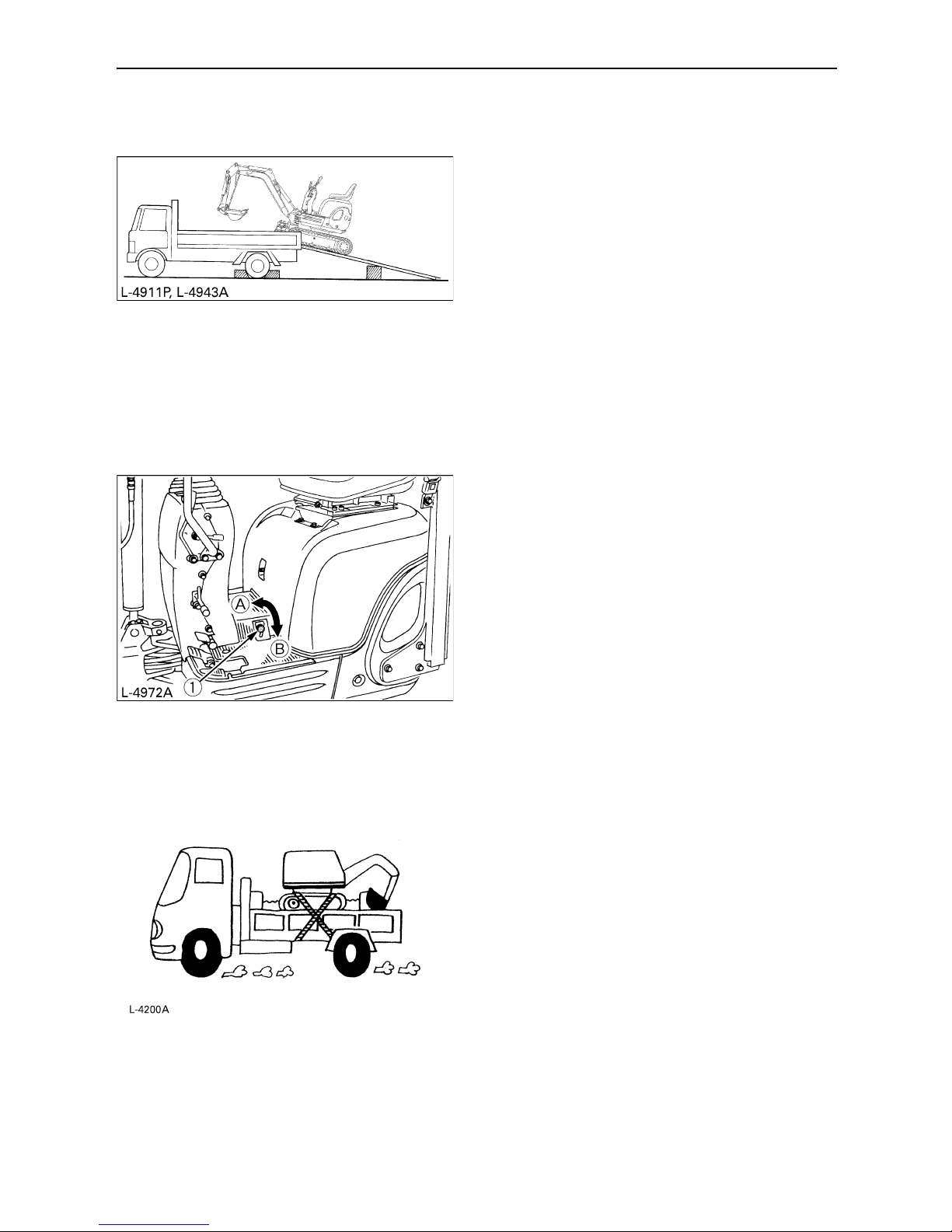
B Transporting on a Truck
To avoid personal injury or death:
A After loading the machine on the
truck, lower the bucket and dozer
onto the truck bed. Lock the swing
frame with the swing lock pin.
Prepare a platform to load or unload the
excavator. Take following steps when using
ramps.
1. Apply the parking brakes of the truck, and
block the drive wheels from both sides.
2. Use fixing plates to secure the ramp
properly. Connect the ramps directly with the
truck bed.
Page 50
31TRANSPORTING THE EXCAVATOR ON A TRUCK
3. For additional safety, use blocks or struts
under the ramps and the truck bed.
4. Completely align the ramps and the crawlers
and then drive the excavator slowly up the
ramps with the dozer in the front. After
ensuring that the crawlers are completely on
the truck bed, swivel the upper body around
to the back of the truck.
5. Lock the swing frame with the swing lock pin.
6. Block the crawlers and tie down the
excavator.
7. Before unloading, remove the swing lock pin
and then raise the dozer and bucket from the
truck bed.
(1) Swing lock pin (A)" Unlock"
(B) "Lock"
Page 51

32 LIFTING OF THE EXCAVATOR
LIFTING OF THE EXCAVATOR
To avoid personal injury or death:
A The correct instructions for safe
handling are described here. Read
these carefully before moving the
machine. Make sure that the operating
personnel read the operator's manual
carefully.
B Basics when Lifting with Chains /
Straps
1. The lifting and crane operation is to be
undertaken according to the guidelines
described.
2. As the accessories for lifting mentioned in
this instruction are only given as reference,
the standards concerning strength, control
and other details are based on the
respective applicable guidelines.
B Safety Aspects when Lifting with
Chains / Straps
Abide by following steps when lifting:
1. Do not lift loads that exceed the maximum
load capacity of the crane.
2. Choose correct tackle suitable to the weight,
size and form of the load.
3. First assess the centre of gravity of the load,
position the hook directly over the load and
lift the load so that the centre of gravity of the
load lies as low as possible.
4. The steel wires must be fixed in the middle
of the hook.
5. The load must be lifted vertically from the
ground.
6. Do not enter the working area under
suspended loads and do not move the load
over other persons. The load must be
moved in an area where the equilibrium can
be balanced out easily.
Page 52

33LIFTING OF THE EXCAVATOR
B Lifting Procedure for the
Excavator
To avoid personal injury or death.
A Do not lift the excavator other than at
the 3 points as illustrated.
A Do not use the ROPS for lifting the
excavator.
C General guidelines for lifting
1. Lifting position. (see right illustration)
(1) Pull in the boom completely towards
rear.
(2) Pull in the arm completely.
(3) Pull in the bucket completely.
(4) Swing the boom 0.17 to 0.26 rad. (10 to
15 degrees) to the right from the central
position.
(5) Insert the swing lock pin.
2. Attaching the chains / straps.
(1) Always hook the excavator at three
points. (one on the boom and right and
left of the dozer blade)
(2) Always use a shackle on each lifting
hole when attaching the straps.
(3) Use cushioning material at all places
where the straps contact the machine.
3. Tackle
Choose components with enough strength.
4. Lifting
(1) Lift slowly and safely
(2) Do not enter the excavator area when
lifting.
(3) Lift the excavator horizontally. (Modify
connections according to needs)
(1) Shackle
Page 53

34 MAINTENANCE
MAINTENANCE
MAINTENANCE INTERVALS
No. Check points Intervals
Hour meter indicator
Consequently
Ref.
page
5
0
1
0
0
1
5
0
2
0
0
2
5
0
3
0
0
3
5
0
4
0
0
4
5
0
5
0
0
5
5
0
6
0
0
1
0
0
0
2
0
0
0
1 Fuel Check Daily check 47
2 Engine oil
Check Daily check 48
Change
every
500 hrs
56
3 Hydraulic oil**
Check Daily check 48
Change
every
1000 hrs
57,58
4Coolant
Check Daily check 46
Change
every
2 years
59
5 Lubrication points Check Daily check 49
6 Radiator Check Daily check 50
7 Battery condition Check
every
50 hrs
53
8 Electrical lines Check Daily check, Annual servicing 50,59
9
Greasing of swing
bearing teeth
---
every
50 hrs
53
10 Fan belt tension adjust
every
200 hrs
53
11
Radiator hoses
and clamps
Check
every
200 hrs
54
Change
every
2 years
59
12 Air filter element*
Clean
every
200 hrs
54,55
@
Change
every
1000 hrs
58
13
Greasing of swing
ball bearings
every
200 hrs
55
14
Fuel pipes and
hoses
Check
every
200 hrs
---
Change
every
2 years
60
15 Engine oil filter Change
every
500 hrs
56
Page 54

35MAINTENANCE
A * Clean the air filter more frequently if used in dusty conditions. With heavy soiling, replace the filter.
** When using a hydraulic breaker, change hydraulic oil and return filter according to the table on
"Hydraulic Oil Change (Including Exchange of the Suction Filter in the Hydraulic Tank) under
"EVERY 1000 SERVICE HOURS" in "REGULAR CHECKS AND MAINTENANCE WORK".
A The items listed above (@ marked) are registered as emission related critical parts by KUBOTA in
the U.S.EPA nonroad emission regulation. As the engine owner, you are responsible for the
performance of the required maintenance on the engine according to the above instruction.
Please see the Warranty Statement in detail.
16 Fuel filter
Check
every
50 hrs
51
Change
every
500 hrs
57 @
17
Hydraulic return
filter element
Change
every
1000 hrs
57,58
18
Hydraulic suction
filter element
Change
every
1000 hrs
57,58
19
Front idler and
track roller oil
Change
every
2000 hrs
58
20
Dynamo and
starter motor
Check
every
2000 hrs
58
21 Radiator system Rinse
every
2 years
59
22
Fuel injection
nozzle (Injection
pressure)
Check
every
1500 hrs
58 @
23 Injection pump Check
every
3000 hrs
59 @
No. Check points Intervals
Hour meter indicator
Consequently
Ref.
page
5
0
1
0
0
1
5
0
2
0
0
2
5
0
3
0
0
3
5
0
4
0
0
4
5
0
5
0
0
5
5
0
6
0
0
1
0
0
0
2
0
0
0
Page 55

36 MAINTENANCE
OPENING AND CLOSING OF
PARTS
BOpening/Closing of the Engine
Hood
To avoid personal injury:
A Do not open the engine hood before
stopping engine.
A Do not touch the exhaust muffler or
the exhaust pipe; serious burns can
occur.
For opening, pull up the lever and open the
bonnet.
BKeep the Tools and Operator's
Manual in the Toolbox
DAILY CHECKS
For your own safety and to assure the long life
span of your machine, a careful check should be
made before each operation.
BCoolant Check
To avoid personal injury:
A Move the excavator on to even
ground.
A Make sure that the engine is turned
off.
A Do not open the radiator cap
immediately after the engine has been
stopped; Serious burns can occur
with squirting hot coolant fluid.
A Check the coolant level in the reserve
tank only after the engine has cooled
down.
A Remove the radiator cap only if
absolutely necessary.
The radiator has a reserve tank. Should the
coolant level in the radiator sink, the water will
be automatically be forwarded to the radiator.
Check the coolant level in the reserve tank and
fill up if necessary. The coolant level should be
between the marks "FULL" and "LOW".
A Before delivery coolant was filled with 50 %
water and 50 % antifreeze.
A Do not fill with dirty or salty water.
(1) Lever
(2) Engine hood
(A) "Open"
(1) Tool box
(2) Operator's seat
(1) Reserve tank
Page 56
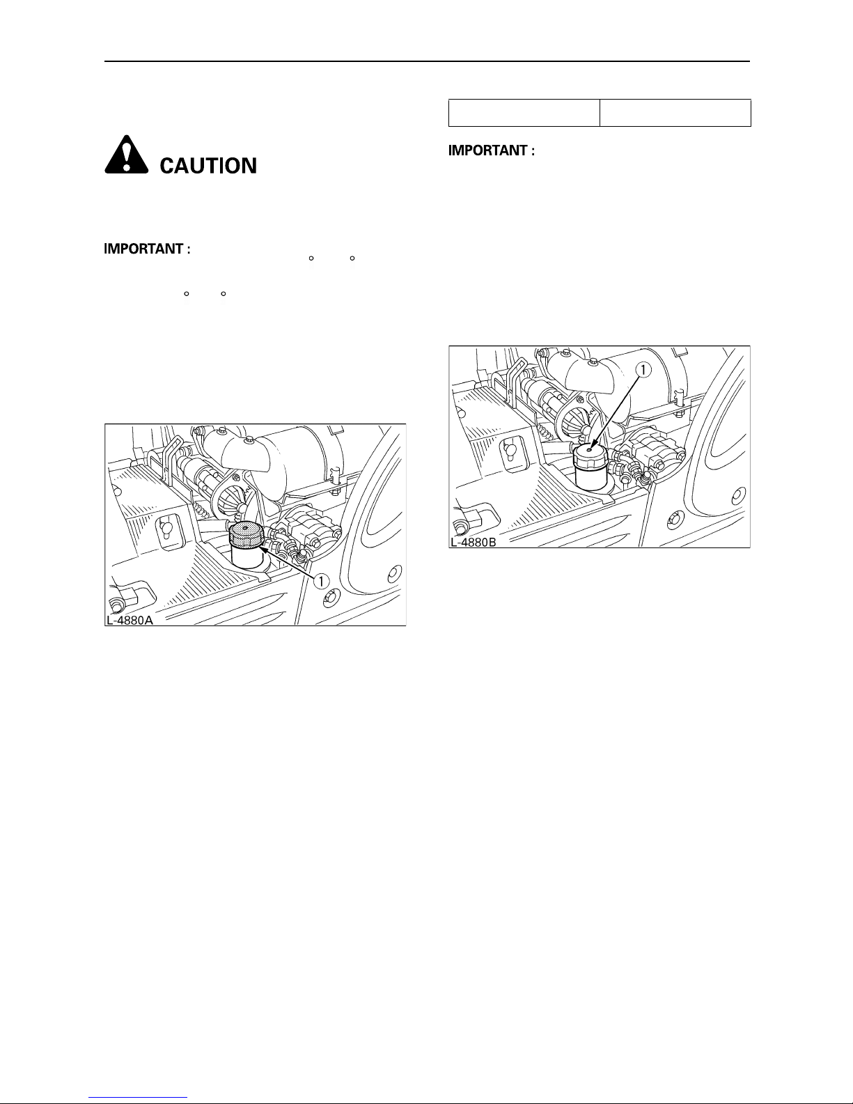
37MAINTENANCE
BCheck Fuel Level
To avoid personal injury:
A Stop the engine before fuelling.
A Do not smoke while fuelling.
A With temperatures over 23 F (-5 C), use
No.2-D diesel fuel, while with temperatures
under 23 F (-5 C), use No.1-D diesel fuel.
A Make sure that the fuel tank is not run empty.
Air enters into the fuel system, and must be
purged before restarting.
1. Check the fuel level in fuel tank.
2. Open the tank cap, and fill with fuel.
A Always fill up fuel after a day's work.
A See "PURGING OF THE FUEL SYSTEM" in
"OTHER ADJUSTMENTS AND
REPLACEMENTS".
A Fuel tank cap has an air breather. Make
sure to clean the air breather when filling up
with fuel.
If the air breather is clogged with mud, the fuel
tank becomes under-pressurized.
(1) Tank cap
Fuel tank capacity 2.9 gals. (11 L)
(1) Air breather
Page 57

38 MAINTENANCE
BCheck Engine Oil Level
To avoid personal injury:
A Stop the engine before checking the
oil level.
Insert the oil gauge rod fully into the prepared
opening, remove again and check the oil level;
if necessary fill with oil. The machine must be on
level ground when checking the oil level.
A Use engine oil with the correct viscosity.
(according the outside temperature)
A After stopping the engine, wait five minutes,
then check oil level. (Excavator must be on
level ground.)
BCheck Hydraulic Oil Level
To avoid personal injury:
A First lower all attachments on the
ground then stop the engine.
A Before filling with oil, wipe away all sand and
dust from around the oil port. Make sure you
use an identical type of hydraulic fluid.
A The excavator has been filled with hydraulic
fluid before delivery. See
"RECOMMENDED OILS". (Do not mix
different makes!)
1. Move the excavator on to level ground.
Extend every cylinder rod up to its centre
position, track width increases 2 ft. 9.9 in.
(860 mm) and place the bucket in contact
with the ground.
2. Check the oil level as to whether it lies on the
centre mark under normal temperature 50 to
86 F (10 to 30 C).
3. Enough oil is present if the oil level lies
between the markings.
4. Should the oil level be too low, fill with oil
through the oil port before starting the
engine. This step is important for the
protection of the hydraulic system.
(1) Oil gauge
(2) Filling port
(A) Required level
(1) Specified oil level
(2) Tank cap
Page 58
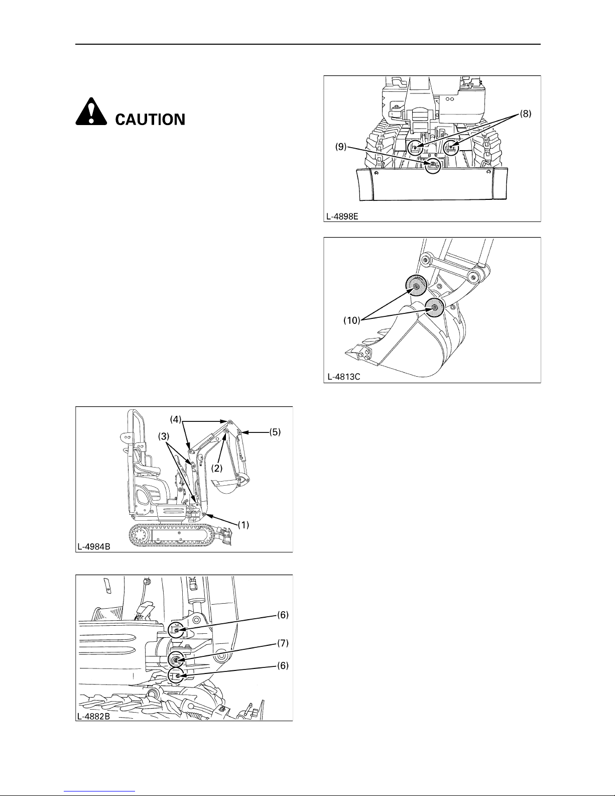
39MAINTENANCE
BLubrication Points
To avoid personal injury:
A First lower all attachments on the
ground then stop the engine.
A While greasing, take care not to step
on the bucket teeth.
A When doing excavation work in water,
generously grease the following
points. After finishing work, grease
again.
Grease the marked grease fittings shown by
arrows in the illustration below.
1. Boom bottom linkage ....................... 1 place
2. Arm bottom linkage .......................... 1 place
3. Boom cylinder boss ........................ 2 places
4. Arm cylinder boss ........................... 2 places
5. Bucket cylinder pin ........................... 1 place
6. Boom swing fulcrum ....................... 2 places
7. wing cylinder boss ............................ 1 place
8. Dozer linkage pin ........................... 2 places
9. Dozer cylinder boss ......................... 1 place
10.Bucket link pin ................................ 2 places
Page 59

40 MAINTENANCE
BCheck Radiator
To avoid personal injury:
A Always stop the engine before
checking the radiator.
A Wear eye protection when cleaning
with compressed air.
1. Check if the fins and ribs are clogged.
If so clean with compressed air or steam.
2. Check the rubber hoses for damage and
replace if cracked or old. Check if the hose
clamps are tight enough.
A Radiator fins and ribs must be clean in order
not to overheat the engine and allow free
flow of air through the cooling elements.
BCleaning of Engine and Electrical
Wiring
To avoid personal injury:
A Always stop the engine before
cleaning the wiring, cables and
engine.
Before starting, check whether flammable
substances have gathered on the battery, the
cables and wiring, the muffler or on the engine.
Remove thoroughly.
BChecking the Electrical Circuit
Check the electrical circuitry for disconnections,
shorts or loose terminals.
BWashing the Whole Machine
A Do not wash the excavator with the engine
running. Water could enter the air filter and
damage the engine.
Make sure that the air filter is kept dry.
BChecking Seat Belt and ROPS
1. Always check condition of seat belt and
ROPS before operating excavator.
2. Replace if damaged.
(1) Radiator
(2) Hose clamps
(3) Rubber hoses
Page 60

41REGULAR CHECKS AND MAINTENANCE WORK
REGULAR CHECKS AND MAINTENANCE WORK
EVERY 50 SERVICE HOURS
BDraining the Water from the Fuel
Tank
Loosen the drain plug at the bottom of the fuel
tank to let sediments, impurities and water out of
the tank. Finally tighten up the plug.
BDraining of the Fuel Filter
To avoid personal injury:
A Before draining the fuel filter, be sure
to stop the engine.
A Do not smoke during inspection.
Check if water or impurities are in the fuel filter
cup, if so clean inside of cup with light oil. For
details see the chapter on "Fuel Filter Change".
(1) Drain plug
(1) Fuel filter cup
Page 61

42 REGULAR CHECKS AND MAINTENANCE WORK
BBattery Service
To avoid personal injury:
A Batteries contain sulphuric acid
which can cause severe burns. Avoid
all contact with skin, eyes or clothing.
Antidote - External: Rinse with plenty
of water. Internal: Drink large
quantities of water or milk.
Call a physician immediately. Eyes:
Rinse with plenty of water for 15
minutes and get prompt medical
attention. Keep batteries out of the
reach of children.
A Before inspection or dismounting the
battery, be sure to turn of the engine
and turn the starter switch to the
"OFF" position.
A When removing the battery, always
disconnect the negative ground cable
first. The reverse when installing a
battery, always connect the ground
cable last. This prevents a possible
explosion caused by sparks.
A Always wear eye protection when
working with the battery.
1. Check the battery fluid level and add distilled
water if necessary.
2. Should battery fluid be spilt, fill with sulphuric
acid solution of the same concentration.
3. Clean the battery caps (ventilation holes)
also.
BBattery Charging
To avoid personal injury:
A When the battery is being activated,
hydrogen and oxygen gases in the
battery are extremely explosive. Keep
open sparks and flames away from
the battery at all times, especially
when charging the battery.
A When charging battery, remove
battery vent plugs.
A When disconnecting the cable from
the battery, start with the negative
terminal first.
When connecting the cable to the
battery, start with the positive
terminal first.
A Do not check battery charge by
placing a metal object across the
terminals.
Use a voltmeter or hydrometer.
1. Make sure each electrolyte level is to the
bottom of vent wells. If necessary add
distilled water in a well-ventilated area.
2. The water in the electrolyte evaporates
during recharging. Liquid shortage damages
the battery. Excessive liquid spills over and
damages the excavator body.
3. To slow charge the battery, connect the
battery positive terminal to the charge
positive terminal and the negative to the
negative, then recharge in the standard
fashion.
(1) Battery (A) Battery fluid level
(B) "Too low"
(C) "Correct"
(D) "Too high"
Page 62
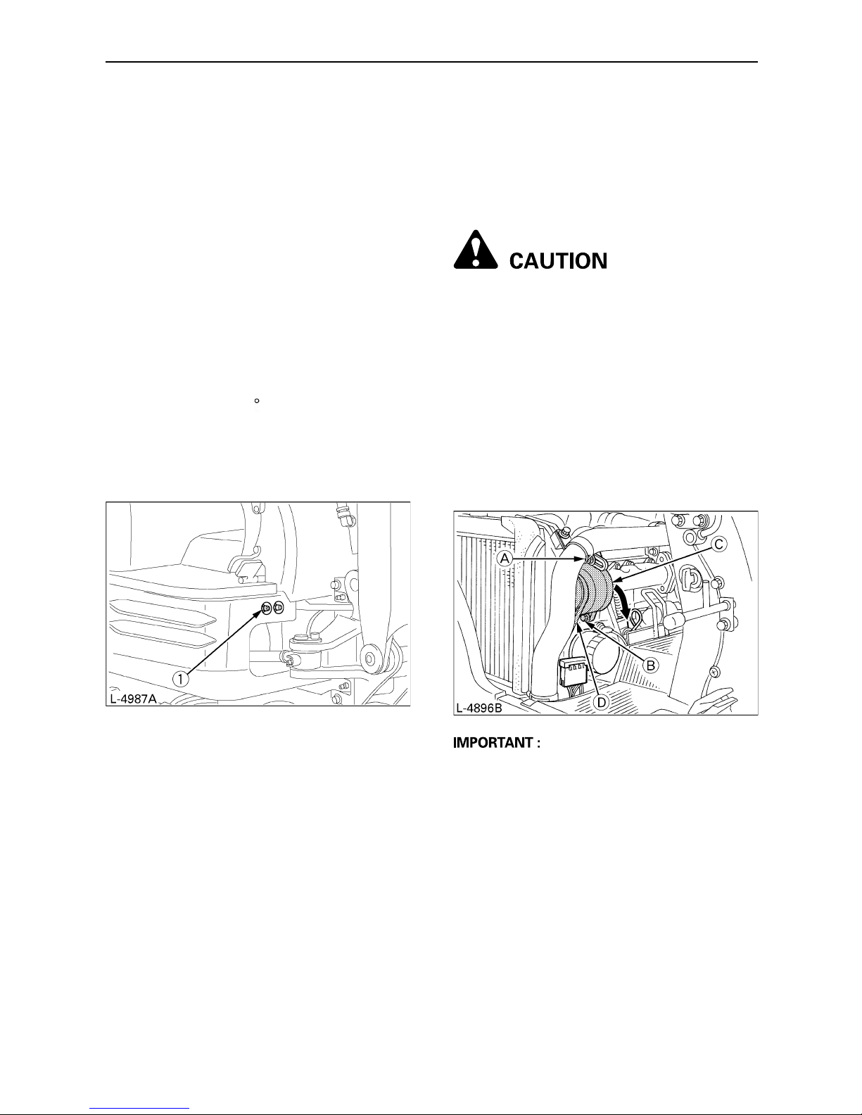
43REGULAR CHECKS AND MAINTENANCE WORK
4. A boost charge is only for emergencies. It
will partially charge the battery at a high rate
and in a short time.
When using a boost-charged battery, it is
necessary to recharge the battery as early
as possible.
Failure to do this will shorten the battery's
service life.
5. When the specific gravity of electrolyte
reaches between 1.27 and 1.29 the charge
is completed.
6. When exchanging an old battery for new
one, use battery of equal specification.
BGreasing of Swing Bearing Teeth
1. Fill with grease through the grease fitting (at
the right end side).
2. Grease at each 90 (1.58 rad.) position of
the swing frame.
3. Fill with approx. 0.11 lbs. (50g) of grease
(approx. 20 pumps with the grease gun).
Distribute the grease over the teeth.
EVERY 200 SERVICE HOURS
Do all 50 hour servicing at the same time.
BChecking the Fan Belt Tension
C Check and adjustment of the fan belt
tension
To avoid personal injury:
A First stop the engine.
A After servicing, make sure to replace
the belt cover in its original position.
1. Press the fan belt (D) down in the middle,
with a force of approx. 22 lbs (10 kg). The
belt tension is correct if it deflects about 0.31
in. (8 mm). If otherwise, loosen bolt (A) and
(B) and shift the dynamo (C) in the direction
shown by the arrow.
2. Replace the fan belt if worn out, cracked or
torn.
A If the engine is run with a loose fan belt, the
belt could slip and cause overheating of the
engine or insufficient battery charging.
Check fan belt tension regularly.
A Should the fan belt snap or jump out, the
lamp for battery charge will light up. Stop the
engine immediately.
(1) Grease fitting (for Bearing teeth)
Page 63

44 REGULAR CHECKS AND MAINTENANCE WORK
BChecking the Radiator Hoses
To avoid personal injury:
A Wait long enough for the radiator
coolant to cool down.
Check the water hoses are properly attached.
This check should be carried out every 200
hours or every 6 months, whichever comes first.
1. Should the hose clamps be loose or water
leak, tighten the hose clamps properly.
2. Should the radiator hoses be swollen, aged
or cracked, they must be replaced and the
hose clamps tightened again properly.
BInspection and Cleaning of the Air
Filter Element
Open the engine hood and remove the dustcover. Take out only outer element, clean the
element, case interior and reassemble. During
reassembly, take care to install the dust-cover
so that its TOP mark (arrow) faces upwards. Do
not remove the inner element.
A Should the machine be used in extremely
dusty areas, the air filter element must be
inspected and cleaned more frequently than
in the specified maintenance periods.
A The air filter has a dry element, keep free
from oil.
A Do not run the engine without the air filter.
(1) Radiator hoses
(2) Hose clamps
(1) Outer element
(2) Inner element
(3) Case
(4) Dust-cover
(5) Clamps
Page 64

45REGULAR CHECKS AND MAINTENANCE WORK
BAir Filter Maintenance
To avoid personal injury:
A Wear eye protection.
C Cleaning with compressed air
Pressure of compressed air must be under 205
kPa (2.1 kgf/cm , 30 psi), and the cartridge
should be blown clean from the inside to the
outside until the dust deposits are completely
clear.
A If the air suction is still inadequate, or the
colour of the exhaust gases is abnormal
even after the cleaning, the air filter element
must be replaced.
BGreasing of the Swing Bearing
1. Grease through the respective grease fitting.
2. Grease at each 90 (1.58 rad.) position of
the swing frame.
3. Using the grease gun, apply 5 shots at every
position.
BChecking Fuel Line and Intake Air
Line
1. Check to see that all lines and hose clamps
are tight and not damaged.
2. If hoses and clamps are found worn or
damaged, replace or repair them at once.
(1) Grease fitting
Page 65
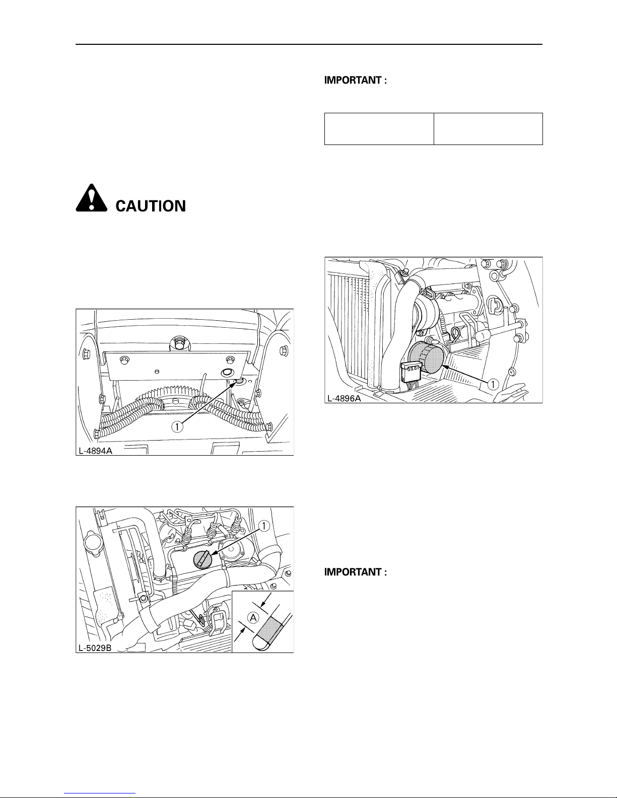
46 REGULAR CHECKS AND MAINTENANCE WORK
EVERY 500 SERVICE HOURS
Do all 50 hour servicing at the same time.
B
Engine Oil Change (Change the
engine oil every 500 hours, or every
1 year in the case that service hour
is less than 500 hours)
To avoid personal injury:
A First stop the engine and wait long
enough for the oil to cool down.
1. Remove the drain plug on the underside of
the engine and drain all oil.
2. Re-tighten the drain plug.
3. Fill with new oil up to the required level.
4. Let the engine idle for approx. 5 min. Check
the engine oil level. To check the engine oil
level, insert the oil gauge completely into the
respective port opening and pull out again. If
the oil level lies between both markings, no
oil must be added.
A Regardless of the service hours, an engine
oil change is due every 1 year.
B
Replacing Engine Oil Filter (Replace
the engine oil filter every 500 hours,
or every 1 year in the case that
service hour is less than 500 hours)
1. Remove the cartridge with the supplied filter
wrench.
2. Oil the O-ring of the new oil filter cartridge
lightly. Then tighten the oil filter cartridge by
hand.
3. Fill engine oil to the specified level.
4. Let the engine run for approx. 5 min. and
make sure that the engine oil control lamp
does not light up. Then stop the engine.
5. The engine oil level will sink parallel to the oil
filter capacity after the engine is started. It is
necessary to add oil.
A Always check the oil level when replacing
the filter.
(1) Drain plug
(1) Oil filling port (A) Required level
Engine oil volumes
(with engine oil filter)
approx. 0.58 gal.
(2.2 L)
(1) Oil filter cartridge
Page 66
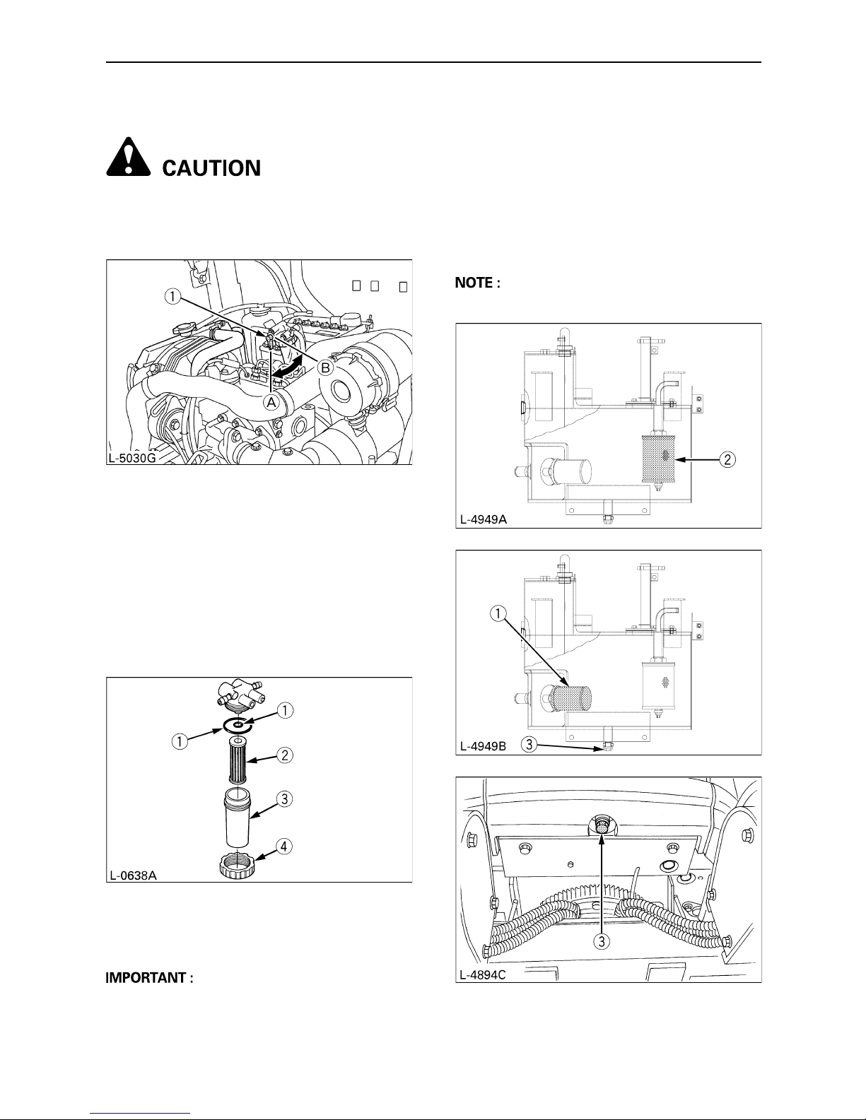
47REGULAR CHECKS AND MAINTENANCE WORK
BReplacing Fuel Filter Element
To avoid personal injury:
A Keep away from fire.
1. Close the fuel shutoff-valve.
2. Unscrew the retaining ring and remove the
filter cup. Clean the inside of the cup with
light oil.
3. Remove and replace the element with new
one into position and tighten a up by hand.
4. Reassemble the filter cup and the retaining
ring.
5. Open the fuel shutoff-valve again.
A After replacement of the element, the fuel
system must purged.
EVERY 1000 SERVICE HOURS
Do all 50, 200 and 500 hour servicing at the
same time.
BHydraulic Oil Change (Including
Replacing of the Suction Filter and
the Return Filter in the Hydraulic
Tank)
A Contact your KUBOTA dealer for details.
(1) Fuel shutoff-valve (A) "Open"
(B) "Closed"
(1) O rings
(2) Element
(3) Filter cup
(4) Retaining ring
(1) Suction filter
(2) Return filter
(3) Drain plug
Page 67
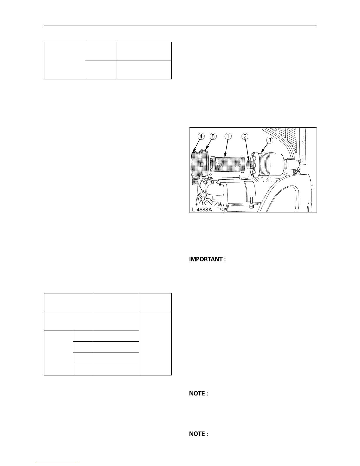
48 REGULAR CHECKS AND MAINTENANCE WORK
BHydraulic Oil Check with
Hydraulic Breakers
The hydraulic oil change after 1000 operating
hours in the operator's manual is based on the
type of work done. The following inspection
measures are valid when hydraulic breakers are
used:
1. Changing and filling up of hydraulic oil
(1) The hydraulic oil must be changed more
often when breakers are used because
the machine is subject to harder
conditions than at normal excavating
work.
(2) Use only the recommended oils
mentioned in the operator's manual
when changing or topping up oil.
(3) When filling up oil, do not mix oils of
different makes.
2. Changing the return filter and oil
(1) The filter must be changed more often
because of contamination resulting
from the frequent assembly and
disassembly of the hoses.
(2) Use the correct replacement filter.
(3) Oil change according to operating
hours.
EVERY 1000 SERVICE HOURS OR
ONCE A YEAR
BReplacing Air Filter Element
Open the engine hood and remove the dustcover.
Remove and replace the outer element and
inner element with new elements.
When reassembling, install the dust-cover so
that its TOP mark (arrow) faces up-wards.
A Shorten the replacement period if using in
lots of dust or sandy areas.
EVERY 1500 SERVICE HOURS
BChecking Fuel Injection Nozzle
(Injection Pressure)
Consult your local KUBOTA Dealer for this
service.
EVERY 2000 SERVICE HOURS
Do all 50, 200, 500 and 1000 hour servicing at
the same time.
BChanging Front Idler and Track
Roller Oil
A Contact your KUBOTA dealer for details.
BChecking the Dynamo and Starter
Motor
A Contact your KUBOTA dealer for details.
Hydraulic oil
volumes
Hydraulic
tank
approx. 3.28 gals.
(12.4 L)
Whole oil
volumes
approx. 3.80 gals.
(14.4 L)
Hydraulic oil
Return Filter
Suction
Filter
Normal
excavator work
every 1000
Hrs.
1000 Hrs.
Breaker
work
Portion
20% every 800 Hrs.
40% every 600 Hrs.
60% every 400 Hrs.
more every 200 Hrs.
(1) Outer element
(2) Inner element
(3) Case
(4) Dust-cover
(5) Clamps
Page 68
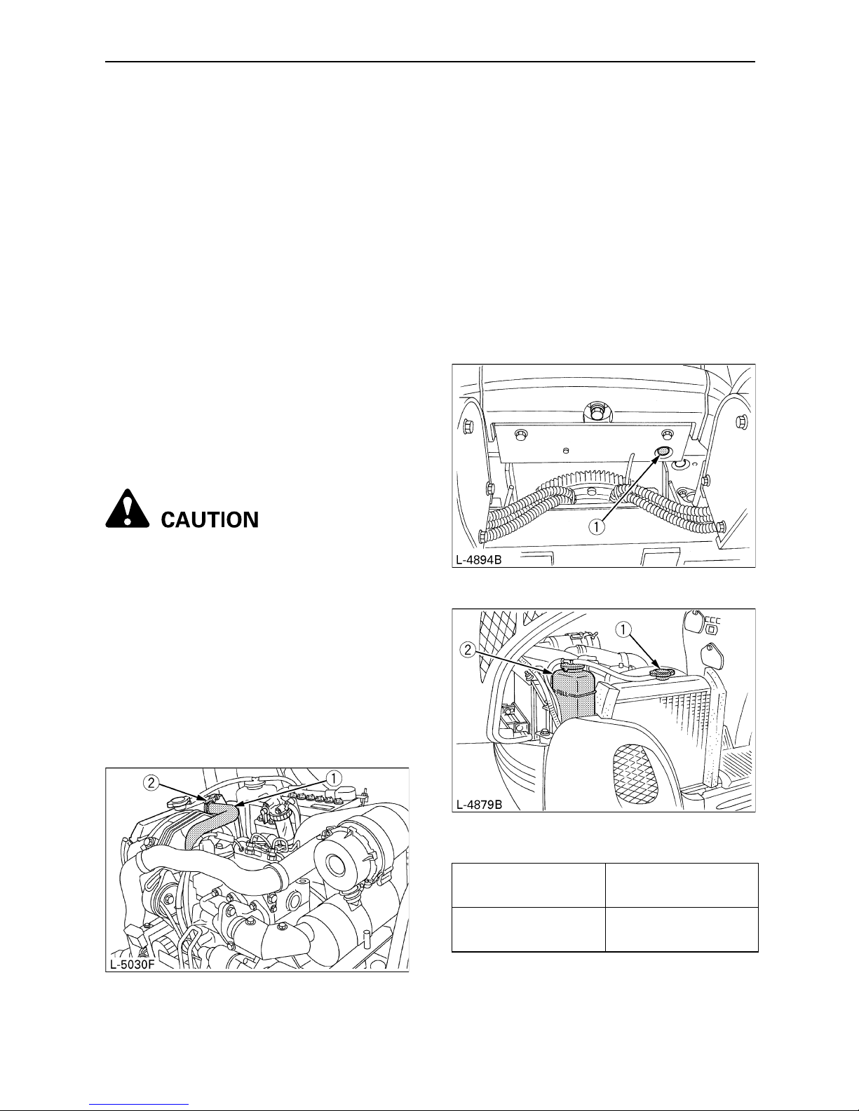
49REGULAR CHECKS AND MAINTENANCE WORK
EVERY 3000 SERVICE HOURS
BChecking Injection Pump
Consult your local KUBOTA Dealer for this
service.
ANNUAL SERVICING
BElectrical Wiring and Fuses
Check the terminals periodically for proper
connections. Loose wiring or damaged cables
can cause improper functioning of the electrical
system. Short circuiting, electrical leaks and
other expensive problems could arise. Check
wiring and replace damaged components
immediately. If a fuse blows out soon after
having been replaced, contact your nearest
KUBOTA dealer. Never use a fuse other than
specified.
BIENNIAL SERVICING
To avoid personal injury:
A Do not loosen the radiator cap before
the radiator has cooled down
sufficiently. Then only loosen the cap
and allow enough time for the
pressure in the system to be released.
Now remove the cap completely.
BReplacement of Radiator Hoses
Replace radiator hoses and hose clamps ever
two years. If the hoses are swollen, hard or
cracked, they must be replaced earlier.
BChanging Radiator Coolant
(In case of long-life coolant fluid)
Stop the engine and wait until it has cooled
down completely.
1. Open the drain plugs on the bottom of the
radiator and drain coolant completely.
2. To clean, rinse the radiator with water.
3. Close the drain plug and fill the radiator with
coolant fluid. Let the engine idle for about 5
min., stop the engine and check the coolant
level.
4. The machine has been shipped filled with
50% anti-freeze solution.
(1) Radiator hoses
(2) Hose clamps
(1) Drain plugs
(1) Radiator cap
(2) Reserve tank
Radiator
approx. 0.61 gal.
(2.3 L)
Reserve tank
approx. 0.13 gal.
(0.5 L)
Page 69
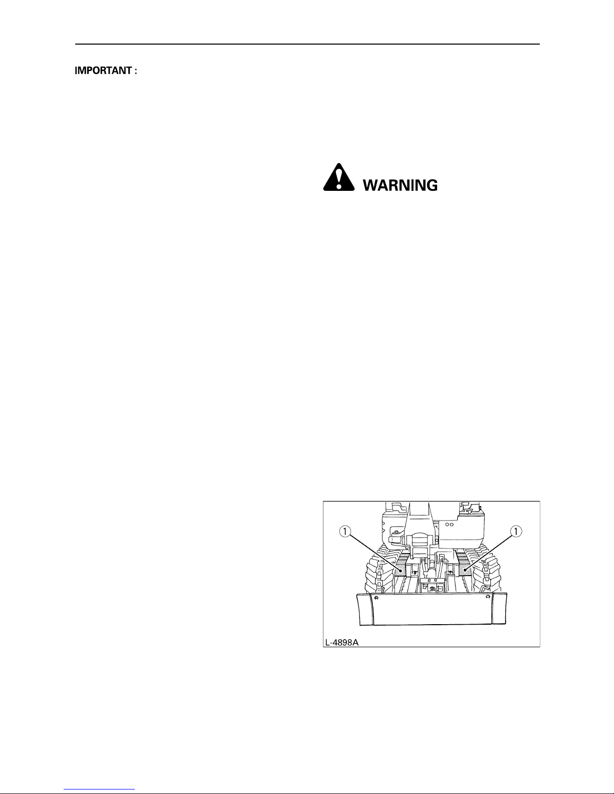
50 REGULAR CHECKS AND MAINTENANCE WORK
A Do not operate the engine without coolant.
A To fill the radiator system use fresh water
and anti-freeze fluid.
A When the anti-freeze is mixed with water,
the ratio must not exceed 50%. (a 50/50 mix
is recommended)
A Tighten the radiator cap properly. If the cap
is loosely or not properly fitted, overheating
of the engine can result due to coolant fluid
loss.
BReplacing Fuel Hose
Replace the hoses and clamps.
(See "Checking Fuel and Intake Air Line" every
2000 hours maintenance.)
BReplacing Intake Air Line
Replace the hoses and clamps, if necessary.
(See "Checking Fuel and Intake Air Line" every
2000 hours maintenance.)
OTHER SERVICING
BCleaning the Track Frame
Telescopic Beams
When the track frame telescopic beams are
clogged or covered with soil or sand, clean the
slide pipes as follows according to need.
To avoid the personal injury or death:
A Place the machine on even ground
when cleaning the track frame
telescopic beams.
1. First lift the machine off the ground using the
dozer blade and boom functions.
2. Switch the track width change / dozer select
lever to the "Track width change" position.
3. Pull the control lever backward, and expand
the track width to 2ft. 9.9in. (860mm).
4. Remove soil and sand adhered to the
telescopic beams, then put grease evenly
around the pipes. Make sure all 4 telescopic
beams are greased.
5. Retract and expand the track width
repeatedly a few times by moving the control
lever, so that the grease is spread
adequately.
6. Switch the track width change / dozer select
lever to the "Dozer" position.
7. Place the machine down on the ground
carefully by moving the dozer blade and the
boom.
(1) Track frame telescopic beams
Page 70

51OTHER ADJUSTMENTS AND REPLACEMENTS
OTHER ADJUSTMENTS AND REPLACEMENTS
PURGING OF THE FUEL SYSTEM
1. Fill up the excavator with fuel.
2. Turn the starter key to the position "ON".
3. The air in the fuel system will be purged
within one minute.
A If the purging was insufficient, and the
engine dies immediately after starting. In this
case repeat steps (2) to (3) again.
ADJUSTMENT OF CRAWLERS
C To loosen the crawlers, follow the
following procedure:
To avoid personal injury:
A Do not loosen the grease fitting
completely or too quickly. Otherwise
grease under high pressure in the
tension cylinder could squirt out.
A Do not crawl under the excavator.
1. Using a socket wrench, loosen the grease
fitting a few turns.
2. When grease oozes out from the thread,
rotate the crawler and loosen the crawler in
the lifted position (see illustration).
After adjustment is completed:
Using the socket wrench, tighten the grease
fitting.
Tightening torque must be between 72.3 to 79.6
ft-lbs (98 to 108 N-m, 10 to 11 kgf-m).
A If the crawlers are too tight, wear is
increased.
A If the crawlers are too loose, the crawler
shoes may collide with the sprocket, and
wear is increased.
The crawler may dislocate or come off.
A Clean the crawler after every use.
A Should the crawler tension be heightened
due to mud sticking, lift the crawler with the
help of the boom, arm and bucket, idle the
engine and remove the mud from the
crawler, especially from the openings of the
link plate, carefully.
C Tension the crawlers as specified:
1. Apply grease (2) to the grease fitting (1).
(A) "PREHEAT"
(B) "OFF"
(C) "ON"
(D) "START"
(1) Grease fitting
(2) Grease gun
Page 71

52 OTHER ADJUSTMENTS AND REPLACEMENTS
2. Tension the crawler in the lifted position, so
that the distance "A" (clearance between the
track roller and the inside surface of the
crawler) is 0.39 to 0.59 in. (10 to 15 mm)
(see illustration), (In this case, the crawler
seam is positioned on the top centre
between the idler and the sprocket.
To avoid serious injury or death:
A Do not work under the machine in this
condition.
A For your safety do not rely on
hydraulically supported devices, they
may leak down suddenly drop or be
accidentally lowered.
A Make sure that no obstacles, such as
stones, are caught in the crawler. Remove
such obstacles before adjusting the crawler
tension.
A Crawler seam
The ends of the rubber crawler are joined
with a seam. When adjusting the crawlers,
the seam must be positioned on the top
centre between the idler and the sprocket.
If the seam is positioned incorrectly, the
crawlers will be tensioned to loosely, and a
further readjustment will be necessary.
A Rotate the crawler after adjustment one to
two times to check the tension.
A Additionally the following points are to be
observed when adjusting rubber crawlers.
(1) If the crawler slackens more than 0.98
in. (25 mm), readjust them.
(2) Check crawler tension 30 hours after
initial use and readjust if necessary.
Check and adjust thereafter every 50
service hours.
BSpecial Information when Using
Rubber Crawlers
1. When turning, preferably make a slow swing
turn. Avoid spin turns to lessen lug wear and
ingress of dirt.
2. The relief valve may be activated if too much
dirt and sand clog the crawlers. In this case
move the machine for a short distance
straight backwards to let the earth and sand
fall off, then a turn can be made.
3. Avoid using rubber crawler on riverbeds,
stony underground, ferro-concrete and iron
plates. The rubber can be damaged as well
as crawler wear increasing.
(1) Seam (Mark " ") (A) 0.39 to 0.59in.
(10 to 15 mm)
Page 72

53OTHER ADJUSTMENTS AND REPLACEMENTS
CHANGING THE BUCKET
To avoid personal injury:
A When the coupling pins are removed
or installed, chips may come off.
Always use gloves, goggles and a
helmet.
A When the change of the equipment
must be performed with the engine
running, always work as a 2-person
team.
One person sits in the operator's seat
and the other works on the machine.
A Do not use your fingers to center the
holes, since they may be injured or
even cut in case of sudden or
uncontrolled movements.
A Read the manual of the attachment to
do a correct operation safely when
other attachments are installed
instead of Kubota specified bucket.
FUSES
BReplacing Fuses
1. Remove the cover of the fuse box.
2. Replace the burnt out fuse with a fuse
having the same capacity.
BFuse Capacities and Circuits
BSlow Blow Fuse
Slow blow fuse is provided to protect the
electrical circuits. If the fusible link is blown,
check the electrical circuits for problems and
then replace with a new compatible slow blow
fuse.
(1) Fuse box
No. Capacity Circuit
1 15A Fuel cut solenoid
2 10A Working lamp, Horn
35A
Hour meter, Fuel pump,
Control lamp, Regulator
4 5A Timer relay
15A, 10A, 5A Spare fuses
(1) Slow blow fuse
Page 73

54 TROUBLESHOOTING
TROUBLESHOOTING
If the excavator does not give the desired performance, or when problems arise, refer to the table below
and take appropriate measures.
Trouble Cause Countermeasure
Engine
Starting difficulties
Fuel is too viscous
D Check fuel tank and filter
D Remove impurities and water
D If necessary, replace filter
Air or water in the fuel
system
D Remove water from the fuel tank
D Check fuel pipe joint bolts and nuts for
looseness
D Purging of the fuel system (for fuel
filter and injection pump, see
"PURGING OF THE FUEL SYSTEM"
in "OTHER ADJUSTMENTS AND
REPLACEMENTS".)
Oil viscosity is too high so
that the engine funs
sluggishly in winter
D Pour hot water over the radiator
Battery is almost dead;
insufficient compression
D Recharge battery
Insufficient
engine power
Low fuel level D Check fuel and add if necessary
Clogged air cleaner D Clean the air filter element
Engine
suddenly stops
Low fuel level
D Check fuel and add if necessary
D Purge the fuel system
Abnormal exhaust
gas colour
Poor fuel D Use high quality fuel
Too much engine oil D Drain engine oil to prescribed oil level
Water temperature
warning lamp ON
(Temperature too
high for overheating)
Worn or torn fan belt D Adjust or replace
Coolant level too low D Fill to prescribed level
Radiator grill or fins are
clogged
D Clean
Coolant is contaminated
with rust from the cylinder
head or crank case
D Replace coolant fluid and add anti-rust
Defective radiator cap
(Evaporation)
D Replace
Corroded coolant pipes D Clean
Continuous operation
under full load
D Reduce load
Engine oil level too low D Fill to prescribed level
Use of poor fuel D Use prescribed fuel
Page 74

55TROUBLESHOOTING
Hydraulic
system
Boom, arm, bucket,
drive, swing and
dozer power is too
low
Hydraulic oil level too low D Add oil
Leakages of hoses and / or
joints
D Replace hose or joint
Non- function of
swing motor
Swing lock pin is in lock
position
D Remove swing lock pin in unlock
position
Drive
system
Deviation of drive
direction
Blocked through stones D Remove
Crawler too loose or too
tight
D Adjust accordingly
Trouble Cause Countermeasure
Page 75

56 OPERATION IN COLD WEATHER CONDITIONS
OPERATION IN COLD WEATHER CONDITIONS
PREPARATION FOR OPERATION
IN COLD WEATHER
1. Replace engine oil and hydraulic oil with
those of viscosities suitable for cold weather.
2. In cold weather, battery power drops, and
the battery fluid may freeze if the battery is
not sufficiently charged. To prevent the
battery fluid from freezing, be sure to keep
the battery charged at least 75% or more of
its capacity after operation. To ease next
starting, it is recommended to keep the
battery stored in closed or heated rooms. If
the battery fluid level is too low, do not add
after operation, but add with the engine
running before the next operation.
3. Add anti-freeze to coolant in the radiator and
reserve tank, if the ambient temperature is
expected to drop below 32 F (0 C). Mixing
ratio of water and anti-freeze depends on
the expected ambient temperature.
However, a 50/50 mix is recommended.
A Mixing ratio between water and anti-freeze
A Use permanent anti-freeze or long-life
coolant.
A Drain the coolant completely and clean the
radiator inside then fill with the water and
anti-freeze mixture.
A As the anti-freeze also acts as an anti-
corrosive, it is not necessary to add an
additive to the water and anti-freeze mixture.
A See "Coolant check" under "DAILY
CHECKS" in "MAINTENANCE" for radiator
fill volumes.
PROCEDURE AFTER WORK
CARRIED OUT
Clean the excavator thoroughly after work and
wipe dry. Otherwise mud and earth on the
crawlers could freeze if the temperature drops
below the 32 F (0 C) mark. Operation of the
excavator is then not possible. Store the
excavator in a dry place; if not possible, store on
wooden planks or on mats. If the excavator is
kept on damp or muddy ground, the crawlers
could freeze overnight. Operation of the
excavator is then not possible. Furthermore the
reduction gear may be damaged.
Additionally, the hydraulic cylinders piston rods
must be rubbed dry. Otherwise severe damage
could occur if dirty water seeps through the
seals.
Ambie nt C
Temperature ( F)-5(+23)
-10
(+14)
-15
(+5)
-20
(-4)
-25
(-13)
-30
(-22)
-35
(-31)
Antifreeze %
30 30 30 35 40 45 50
Wate r %
70 70 70 65 60 55 50
Page 76

57LONG STORAGE
LONG STORAGE
To avoid personal injury:
A Do not clean the excavator with the engine running.
A To avoid the danger of exhaust fume poisoning, do not operate the engine in a closed
building without proper ventilation.
A When storing, remove the key from the starter switch to avoid unauthorized persons from
operating the excavator and getting injured.
B Should the Excavator be Stored for a Longer Period of Time, Observe
Following Procedures:
1. The whole excavator should be cleaned thoroughly and in all cases stored indoors. If the excavator
has to be kept outdoors, Iay out wooden planks on even ground, place the excavator on the planks
and cover completely.
2. Do an oil change and grease the excavator.
3. Heavily grease the visible sections of the piston rods.
4. Remove the battery and store indoors.
5. If it is expected that the temperature will sink below the 32 F (0 C) mark, add anti-freeze or drain
coolant completely.
A Wash the excavator after stopping the engine.
If you wash the excavator while running the engine, water may get into the air cleaner through the
intakes causing engine problems.
Carefully, wash but do not splash water over the air cleaner.
B Observe Following Procedures when the Machine is to be Operated after
Long Storage.
1. Wipe off the grease from the hydraulic cylinder rods.
2. Turn on the engine and activate the attachments and the drive mechanisms without load in order to
circulate the hydraulic oil . (If the machine is stored for longer than one month, undertake steps (1)
and (2) once every month)
Page 77

58 LONG STORAGE
Periodic replacement of important component parts
To ensure safety in operation, you are strongly requested to inspect and service the machine at regular
intervals. For added safety, ask your KUBOTA dealer to replace the following important component
parts.
These parts are prone to degradation in material or subject to wear and tear with time. It is difficult to
judge how much they have been affected at regular inspection. It is therefore necessary to replace them
with new ones, whether wear is visible or not after a specified time of use.
If any of them is found worn even before the specified use, it must be repaired or replaced the same
way as other parts.
If any of the hose clamps is found deformed or cracked, the hose clamp must also be replaced.
For the hydraulic hoses other than the ones to be replaced periodically, inspect them for the following
points. If found unusual, tighten them up, replace them.
When replacing the hydraulic hoses, change their O rings and sealings with new ones.
For replacement of the important parts, contact your KUBOTA dealer.
A At the following periodic inspections, check the fuel hoses and hydraulic hoses as well.
List of important component parts
To prevent serious damage to the hydraulic system, use only a KUBOTA genuine hydraulic hose.
Inspection Interval Check Points
Daily Checks Oil leak at fuel and hydraulic hose connections and points
Every month
Oil leak at fuel and hydraulic hose connections and points
Damages at fuel and hydraulic hose (cracks, chafing)
Every year
Oil leak at fuel and hydraulic hose connections and points
Interference, deformation, degradation, twist and other damages (cracks,
chafing) of fuel and hydraulic hoses
No. Component Parts Used Place Q’ty Period
1 Fuel hose
Fuel tank-Fuel filter 2
Every 2 years
or 4000 hours
Fuel filter-Fuel pump 1
Fuel pump-Fuel filter 1
Fuel filter-Fuel nozzle 2
Fuel nozzle-Fuel tank 1
2 Hydraulic hose (suction) Tank-Main pump 1
3 Hydraulic hose (delivery) Main pump-Control valve 2
4 Hydraulic hose (Boom cylinder) Control valve-Boom cylinder 2
5 Hydraulic hose (Arm cylinder) Control valve-Arm cylinder 2
6 Hydraulic hose (Bucket cylinder) Control valve-Bucket cylinder 2
7 Hydraulic hose (Swing cylinder) Control valve-Swing cylinder 2
8
Hydraulic hose
(Dozer cylinder & Track cylinder)
Control valve-Rotary joint 4
Rotary joint-Dozer cylinder 4
Rotary joint-Tank cylinder 2
9 Hydraulic hose (Service port)
Control valve-Joint 1
Joint-Return pipe 1
10 Hydraulic hose (Swivel motor) Control valve-Swivel motor 2
Page 78

59RECOMMENDED OILS
RECOMMENDED OILS
1. Before delivery, the hydraulic oil used was an ISO 46 viscosity grade.
2. Use engine oil API service classification CF/CF-4 or better and SAE10W-30.
3. Use SAE 90 (API, CLA/GL5) as drive unit oil for all seasons.
MIL-Standard
MIL-L-2105C
MIL-L-2105
MIL-L-2105C
MIL-L-2105C
MIL-L-2105C
MIL-L-2105C
Exxon
GX80W-90
NUTO H32
NUTO H46
NUTO H68
BEACON Q2
Light oil No. 2-D (ASTM D975)
Light oil No. 1-D (ASTM D975)
Mobil
Mobilube HD80W-90
Mobilube HD80W-90
Mobilube 46
Mobilube HD80W-90
Mobilube HD85W-140
Mobilube HD80W-140
Mobilube HD80W-90
Mobil DTE-Oil 13
Mobil DTE-Oil 15
Mobil DTE-Oil 16
Mobilux EP2
Shell
Shell Oil S8643
Shell Spirax HD80W
Shell Spirax HD90
Shell Spirax HD140
Shell Spirax HD80W
Shell Spirax HD85W
Shell Tellus T32
Shell Tellus T46
Shell Tellus T68
Shell Alvania EP2
KTC recommends
Excavator Gear Oil 90
Part Number 70000-68700 (1 Quart)
Excavator Hydraulic Fluid 32
Part Number 70000-68720 (5 Gal Pail)
Part Number 70000-68740 (55 Gal Drum)
Excavator Hydraulic Fluid 46
Part Number 70000-68760 (5 Gal Pail)
Part Number 70000-68780 (55 Gal Drum)
Viscosity
SAE
75
SAE
80
SAE
90
SAE
140
Multi-
purpose
ISO
32
ISO
46
ISO
68
Application
In winter or by
low
temperatures
In summer or by
high ambient
temperatures
All-weather
gear oil
In winter or by
low
temperatures
In summer or by
high ambient
temperatures
Grease
Fuel
Fuel under -5 C
(+23 F)
Gear oilHydraulic oil
Page 79

60 RECOMMENDED OILS
C Engine Oil:
A Oil used in the engine should have an American Petroleum Institute (API) service classification
and Proper SAE Engine Oil according to the ambient temperatures.
A Refer to the following table for the suitable API classification engine oil according to the engine
type (with internal EGR, external EGR or non-EGR) and the fuel.
EGR: Exhaust Gas Re-circulation
A The CJ-4 engine oil is intended for DPF (Diesel Particulate Filter) type engines, and cannot be
used on this machine.
C Fuel
A Cetane number of 45 minimum. Cetane number greater than 50 is preferred, especially for
temperatures below -20 C (-4 F) or elevations above 1500 m (5000 ft).
A Diesel fuels specified to EN 590 or ASTM D975 are recommended.
A No.2-D is a distillate fuel of lower volatility for engines in industrial and heavy mobile service.
(SAE J313 JUN87)
Above 25 C (77 F)
SAE30 or SAE 10W-30
SAE 15W-40
0C to 25C (32F to 77F)
SAE20 or SAE 10W-30
SAE 15W-40
Below 0 C (32 F)
SAE10 or SAE 10W-30
SAE 15W-40
Fuel used
Engine oil classification (API classification)
Oil class of engine except external EGR Oil class of engine except external EGR
Ultra Low Sulfur Fuel
[<0.0015% (15 ppm)]
CF, CF-4, CG-4, CH-4 or CI-4
CF or CI-4
(Class CF-4, CG-4 and CH-4 engine oils
cannot be used on EGR type engines
except external EGR with external EGR
Model K008-3 ---
Page 80

61MAIN DIMENSIONS
MAIN DIMENSIONS
ft.in. (mm)
K008-3
(A) (B) (C) (D) (E) (F) (G) (H) (I) (J)
0.8'
(245)
1'
(300)
2'4"3'
(700/800)
2'11"
(880)
2'8"
(825)
2'7"
(800)
9'5"
(2870)
6'8"
(2035)
5'8"
(1715)
4'6"
(1375)
(K) (L) (M) (N) (O) (P) (Q) (R) (S) (T)
3'8"
(1120)
7'4"
(2230)
6'5"
(1945)
0.7'
(200)
0.6'
(180)
6'7"
(2000)
2'7"
(790)
9'2"
(2790)
9'11"
(3025)
10'1"
(3075)
Page 81

62 LIFTING CAPACITY
LIFTING CAPACITY
1. The lifting capacities are based on ISO 10567 and do not exceed 75% of the static tilt load of the
machine or 87% of the hydraulic lifting capacity of the machine.
2. The strokes are as follows.
(1) The load point corresponds to the front bolt part of the arm.
(2) The machine positions are (i) over-front (Blade up), (ii) over-front (Blade down), and (iii) over-
side.
(3) The operating cylinder is the boom cylinder.
3. The bucket of the excavator, the hook, the sling and other lifting accessories are taken into
consideration for the loads.
Machine conditions:
No bucket, all others according to standard regulations.
To avoid personal injury or death:
A It is forbidden to lift loads greater than those values mentioned in the lifting capacity
tables.
A The values mentioned in the table are valid only on even, hard ground. When lifting on
soft ground, the machine 'can tilt over due to the fact that the load is concentrated only
on one side of the machine.
The table values are calculated at the end of the arm without the bucket. In order to find
the allowable loads for machines with bucket, the bucket weight must be subtracted from
the values in the table.
Page 82

63LIFTING CAPACITY
LIFTING CAPACITY
(i) OVER FRONT (BLADE UP)
Unit=1000 lb
(ii) OVER FRONT (BLADE DOWN)
Unit=1000 lb
(iii) OVER SIDE (TRACK WIDTH 2.82 ft)
Unit=1000 lb
MODEL K008-3 SPEC RUBBER
HEIGHT
(ft)
LOAD RADIUS (ft)
0246810
GL
10
8
60.38
40.390.24
2 0.67 0.36 0.23
0 0.61 0.34 0.23
-2 0.61 0.33
-4 0.50
-6
HEIGHT
(ft)
LOAD RADIUS (ft)
0246810
GL
10
8
60.38
40.440.39
2 1.02 0.56 0.40
0 1.04 0.58 0.37
-2 0.81 0.47
-4 0.50
-6
HEIGHT
(ft)
LOAD RADIUS (ft)
0246810
GL
10
8
60.33
40.320.20
2 0.53 0.29 0.19
0 0.48 0.27 0.18
-2 0.47 0.26
-4 0.48
-6
 Loading...