

Page 1
WORKSHOP MANUAL
DUMPER
KC100HD
Page 2

Page 3

MECHANISM
1. SPECIFICATIONS
2. DIMENSIONS
3. ENGINE
4. TRANSMISSION
5. HYDRAULIC SYSTEM (HST)
6. HYDRAULIC SYSTEM (DUMPING)
7. FUEL SYSTEM
8. V-BELT
9. WIRING DIAGRAM
SERVICING
1. TIGHTENING TORQUE
CONTENTS
2. OILS AND FUEL
3. GREASING
4. CAUTION FOR DISASSEMBLING AND REASSEMBLING
5. ADJUSTMENT OF COMPONENT PARTS
6. TESTING OF PRESSURE (HST)
7. REPLACEMENT OF WEAR OUT PARTS
8. TROUBLESHOOTING AND COUNTERMEASURES
9. MAINTENANCE INTERVALS
1
Page 4

MECHANISM
1. SPECIFICATIONS
2. DIMENSIONS
3. ENGINE
4. TRANSMISSION
5. HYDRAULIC SYSTEM (HST)
6. HYDRAULIC SYSTEM (DUMPING)
7. FUEL SYSTEM
8. V-BELT
9. WIRING DIAGRAM
2
Page 5
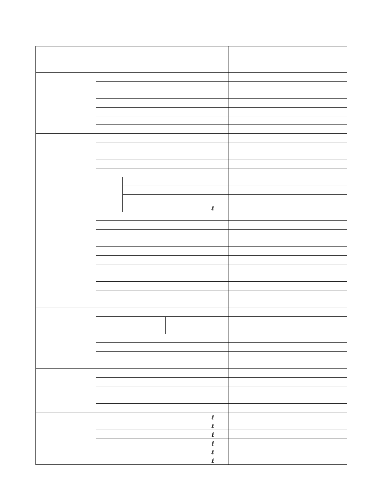
1. SPECIFICATIONS
Model KC100HD
Machine weight (kg) 885
Max. loading capacity (kg) 1200
Engine Model KUBOTA Z482-E3B-CRYM-1
Type Vertical 4-cycle Liquid-Cooled Diesel
No. of cylinder 2
Bore and Stroke (mm) 67 x 68
Total Displacement (cc) 479
Output (KW/rpm) 8.3/3000
Starting system Electric
Dimensions Length (mm) 2640
Width (mm) 950
Height (mm) 2015
Min. ground clearance (mm) 145
Track center-to-center distance (mm) 720
Bed Length (mm) 1470
Width (mm) 855
Height (mm) 320
Capacity Struck / Heaped (
Undercarriage Crawler type Rubber track
Number of drive sprocket teeth 7
Crawler pitch (mm) 72
Track width (mm) 230
Number of track rollers 6 (one side)
Ground contact length (mm) 1180
Gradeability (° ) 25
Alignment Screw type with spring
Ground contact pressure w/o load (kgf/cm
Ground contact pressure w/t load (kgf/cm
Max. traction power (kgf) 1040
Transmission Type HST + Gear shift type transmission
Travelling speed 1st (km/h) 0 - 3.2 / 0 - 2.1
(Forward / Reverse) 2nd (km/h) 0 - 5.8 / 0 - 3.9
Main clutch Belt tension
Steering clutch Tooth clutch
Steering brake Wet multi-plate type
Parking brake Wet multi-plate type
Dumping performance Dumping type Hydraulic
Dumping direction Front / Right side / Left side
Max. Dumping angle (° ) 56 / 60 / 60
Raising time (at 3000rpm) (sec) 7.1
Lowering time (at 30900rpm) (sec) 4.0
Capacity Fuel tank (
Hydraulic oil tank (
Engine oil (
Coolant (
HST oil (
Transmission oil (main / sub) (
) 400 / 520
2
) 0.17
2
) 0.4
) 14.8
) 1.5
) 2.55
) Approx. 2.8
) 13.0
) 3.1 / 0.45
3
Page 6
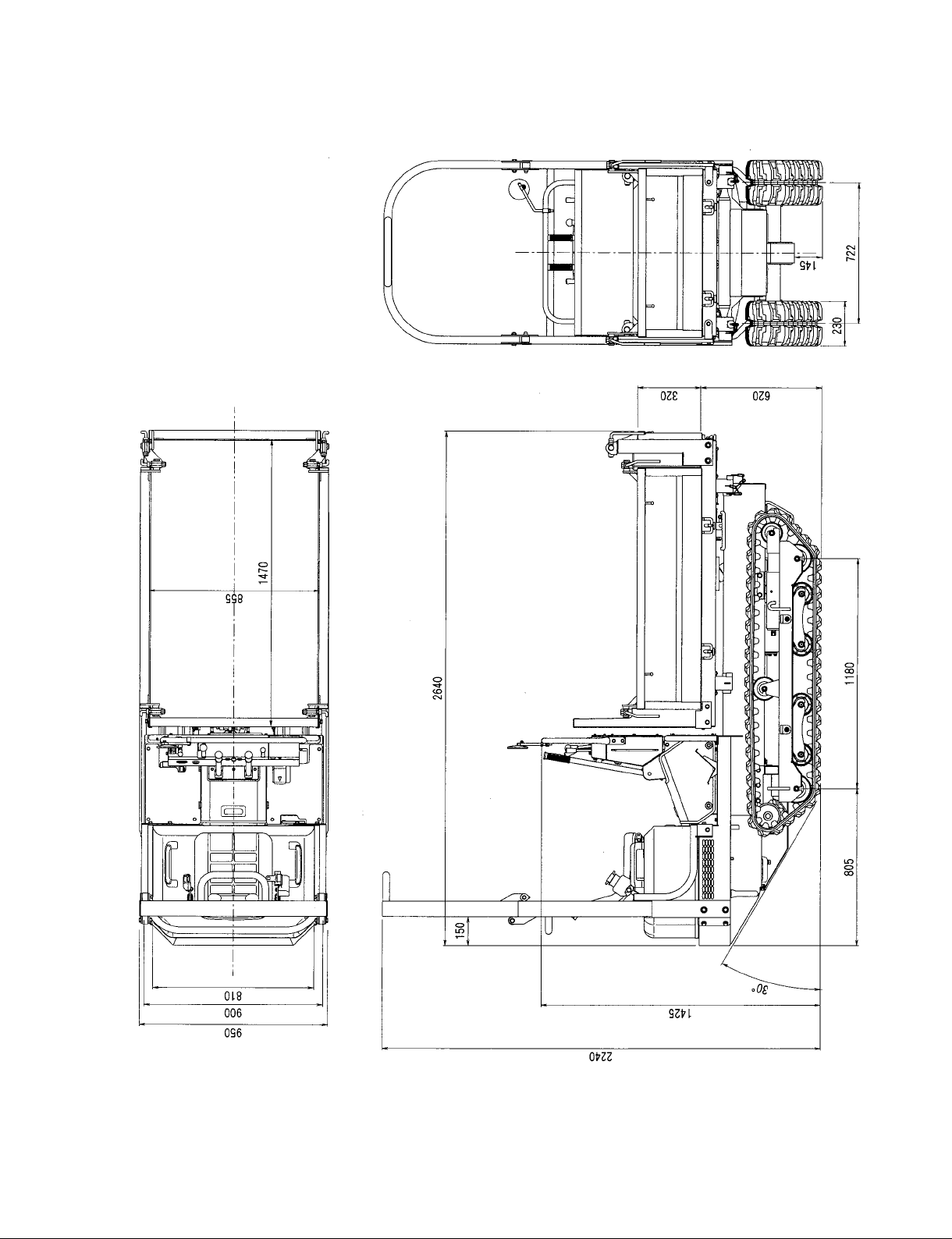
2. DIMENSIONS
4
Page 7
3. ENGINE
Model : Z482-E3B-CRYM-1 / Code No : 1G317-51000
See the WSM / DIESEL ENGINE SM-E3B SERIES
Hard Copy - Code No 9Y121-00132
CD-ROM - Code No 9Y131-00132
Specications
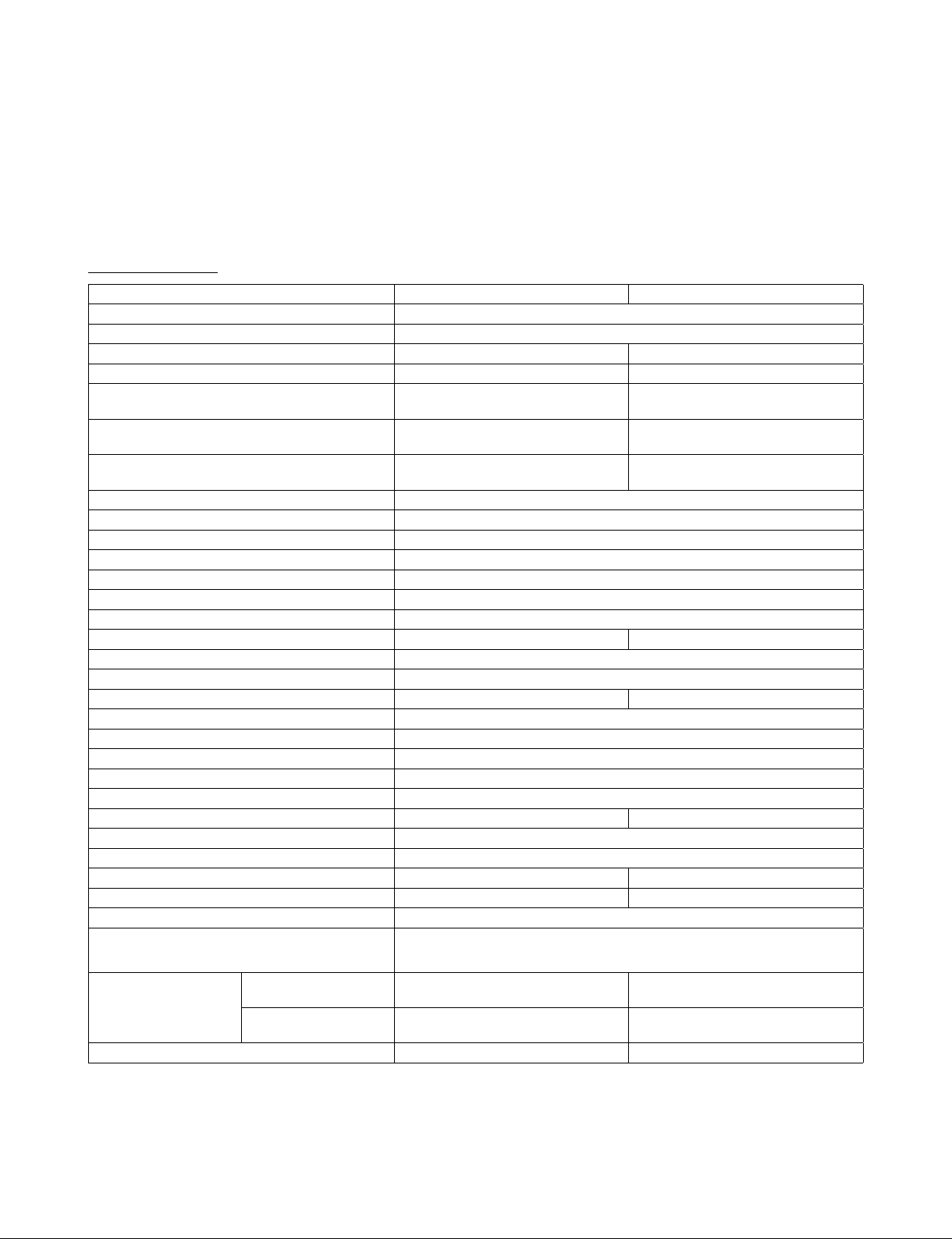
Model Z482-E3B Z602-E3B
Number of Cylinders 2
Type Vertical, Water-cooled, 4 cycle IDI diesel engine
Bore×Stroke 67.0 × 68.0 mm (2.64 × 2.68 in.) 72.0 × 73.6 mm (2.83 × 2.90 in.)
Total Displacement 479.0 cm
ISO Net Continuous
ISO/SAE Net Intermittent
SAE Gross Intermittent
8.10 kW / 3600 min
(10.9 HP / 3600 min
9.30 kW / 3600 min
(12.5 HP / 3600 min
9.90 kW / 3600 min
(13.3 HP / 3600 min
Maximum Bare Speed 3800 min
Minimum Bare Idling Speed 900 to 1000 min
Combustion Chamber Spherical type (E-TVCS)
Fuel Injection Pump Bosch MD type mini pump
Governor All speed mechanical governor
Direction of Rotation Counter-clockwise (viewed from ywheel side)
Injection Nozzle Bosch “Throttle” type
Injection Timing 0.37 rad (21 °) before T.D.C. 0.35 rad (20 °) before T.D.C.
Firing Order 1-2
Injection Pressure 13.73 MPa (140.0 kgf/cm
Compression Ratio 23.5 : 1 24 : 1
Lubricating System Forced lubrication by trochoid pump
Oil Pressure Indicating Electrical Type Switch
Lubricating Filter Full ow paper lter (Cartridge type)
Cooling System
Pressurized radiator, forced circulation with water pump (not included in the basic engine)
Starting System Electric starting with starter
Starting Motor 12V, 0.8kW 12V, 1.0kW
Starting Support Device By glow plug in combustion chamber
EGR None
Battery 12V, 28 AH equivalent 12V, 36 AH equivalent
Charging Alternator 12V, 150W 12V, 480W
Fuel Diesel Fuel No.2-D (ASTM D975)
Lubricating Oil
Class CF lubricating oil as per API classication is recommended.
Oil Pan Depth
Lubricating Oil
Capacity
101 mm (3.98 in.)
Oil Pan Depth
121 mm (4.76 in.)
Weight (Dry) kg(lbs) 53.1 (117) 60.0 (132)
* The specication described above is of the standard engine of each model.
* Conversion Formula : HP = 0.746 kW, PS = 0.7355 kW
3
(29.23 cu.in.) 599.0 cm3 (36.55 cu.in.)
1
-
(rpm)
1
-
(rpm))
1
-
(rpm)
1
-
(rpm))
1
-
(rpm)
1
-
(rpm))
10.1 kW / 3600 min
(13.5 HP / 3600 min
11.6 kW / 3600 min
(15.5 HP / 3600 min
12.5 kW / 3600 min
(16.8 HP / 3600 min
1
-
(rpm)
1
-
(rpm)
2
, 1991 psi)
1
-
( rpm)
1
-
(rpm))
1
-
( rpm)
1
-
(rpm))
1
-
( rpm)
1
-
(rpm))
For details on recommended lubricating oils, see page G-6, 9
2.1 L (0.55 U.S.gals) 2.5 L (0.66 U.S.gals)
2.5 L (0.66 U.S.gals)
–
W10336300
5
Page 8
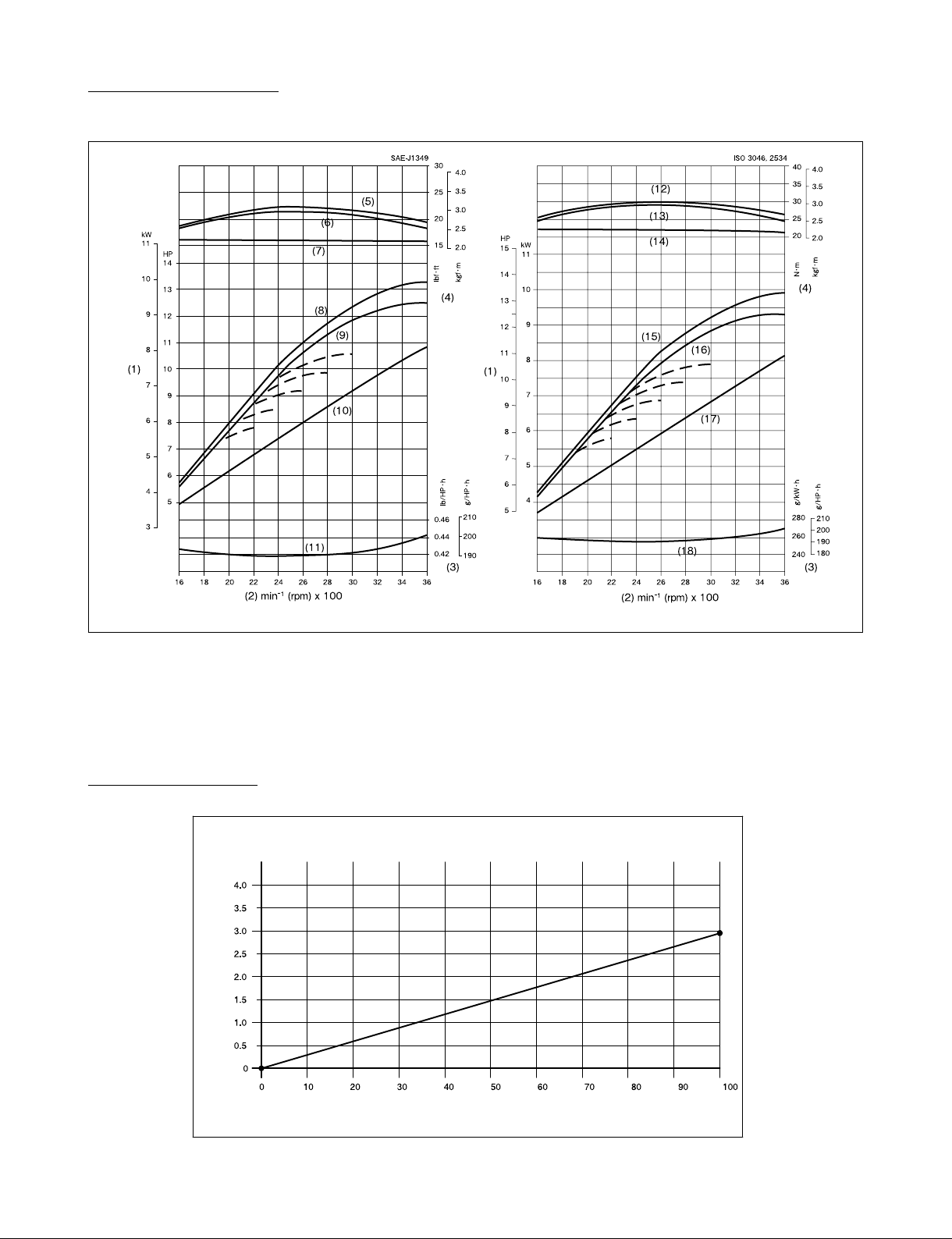
Performance curves
• Z482-E3B
3EEACABEP001A
(1) Brake Horsepower (6) Net Intermittent Torque (11) Net Intermittent B.S.F.C. (15) Gross B.H.P.
(2) Engine Speed (7) Net Continuous Torque (12) Gross Torque (16) Overload B.H.P.
(3) B.S.F.C. (8) Gross Intermittent B.H.P. (13) Overload Torque (17) Continuous B.H.P.
(4) Torque (9) Net Intermittent B.H.P. (14) Continuous Torque (18) Overload B.S.F.C.
(5) Gross Intermittent Torque (10) Net Continuous B.H.P.
Fuel consumption
Fuel consumption KC100HD
Fuel consumption(L/h)
Work load factor (%)
6
Page 9
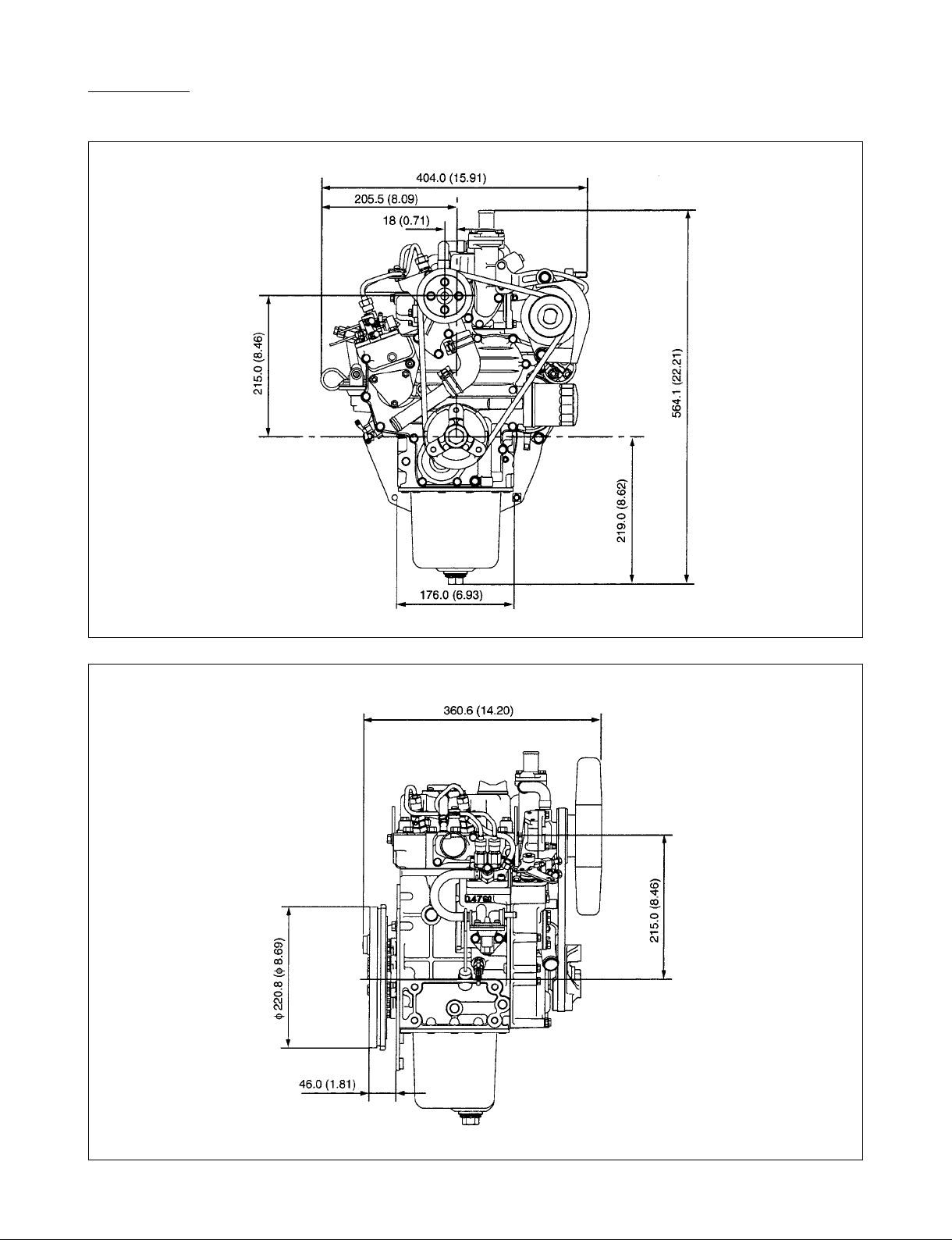
Dimension
• Z482-E3B
Uni : mm (in.)
3EEACABFP001A
Uni : mm (in.)
3EEACABFP002A
7
Page 10
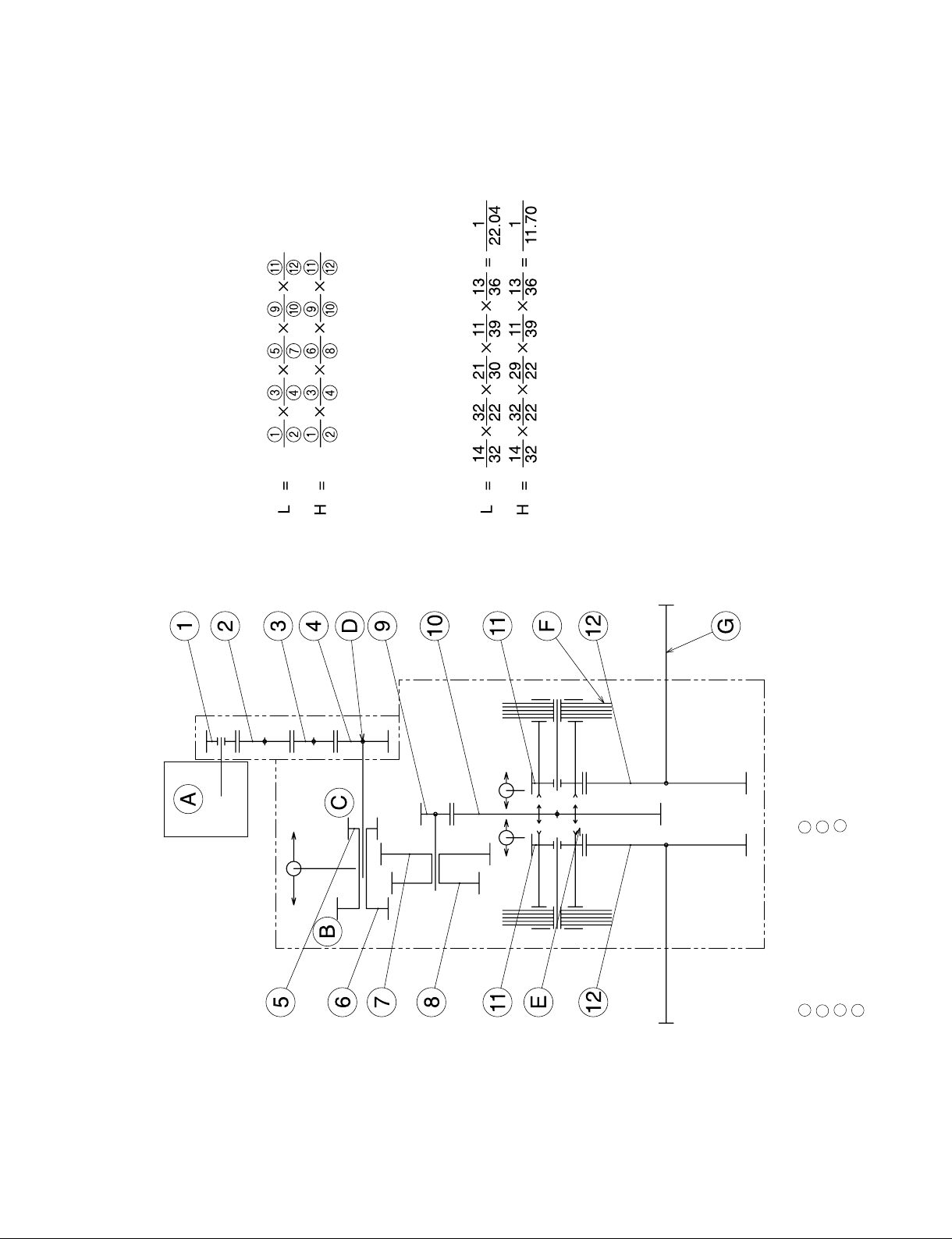
[GEARING]
[GEAR RATIO]
[POWER TRAIN]
4. TRANSMISSION
8
Low (L) G OUTPUT SHAFT
INPUT SHAFT
Hight (H) F BRAKE (STEERING/PARKING)
D
C
B
A HST E CLUTCH GEAR
Page 11
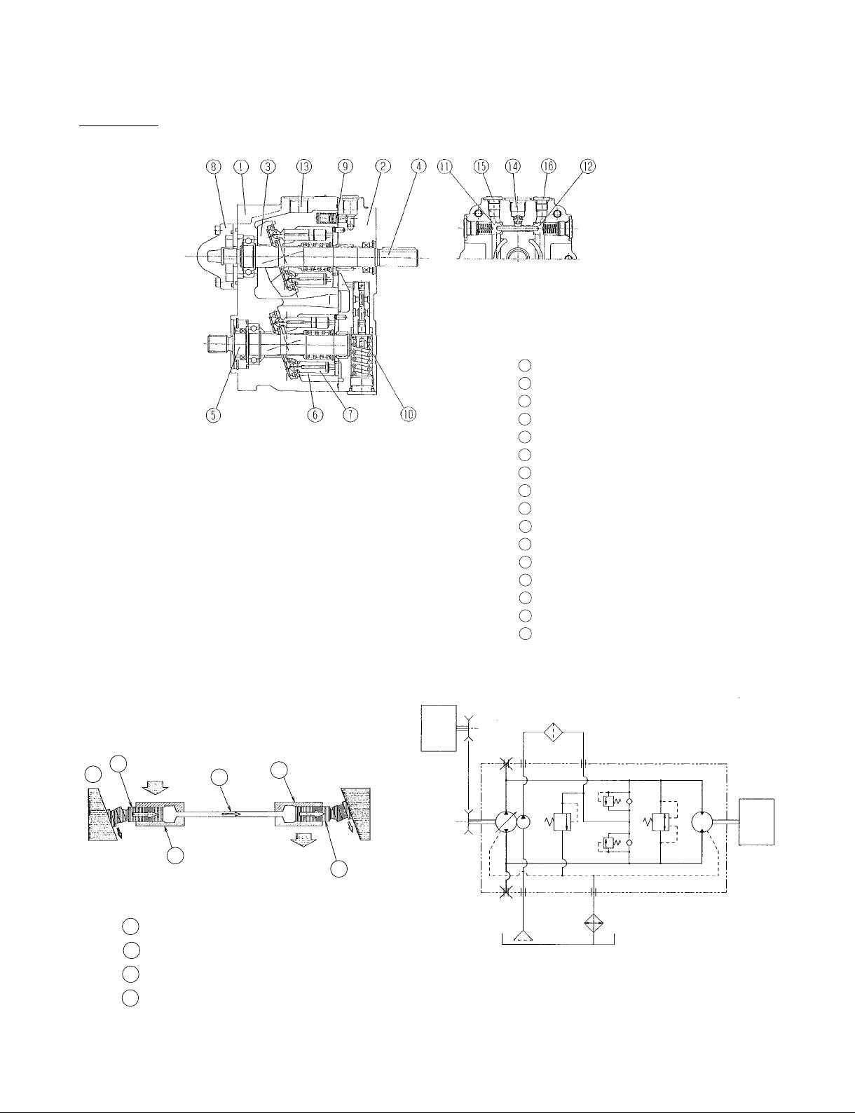
5. HYDRAULIC SYSTEM (HST)
HST unit
Hydraulic pump : 0 ~ 18.2 cm
Hydraulic motor : 18.2 cm
Charge pump : 5.1cm
Relief valve set pressure : 18.5MPa
Charge pressure : 5.0 kgf/cm
Pressure check port ( PF3/8 )
Suction port (PF1/2) [charge pump]
Discharge port (PF3/8) [charge pump]
3
3
2
3
+2.9MPa
1 Housing
Cover
2
Hanger
3
Input shaft
4
Output shaft
5
Block, cylinder
6
Piston
7
Case, charge pump
8
Relief valve (Low pressure)
9
10
Relief valve (High pressure)
11
Neutral valve (Backward)
12
Neutral valve (Forward)
13
Drain port
14
Suction port
15
Pressure check port (Forward)
16
Pressure check port (Backward)
A
B
D
C
A
Pump (Adjustable)
B
Piston
C
Cylinder
D
Flow of oil
E/G
C
T/M
B
9
Page 12
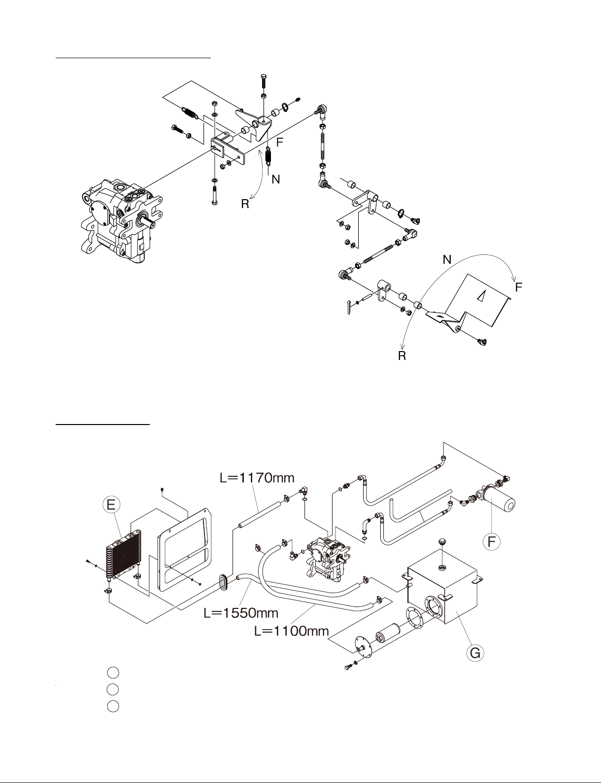
Mechanism of drive pedal
Flow of HST oil
K10H-D010
10
E Oil cooler
F
Oil lter cartridge
G
HST oil tank
K10H-D004
Page 13
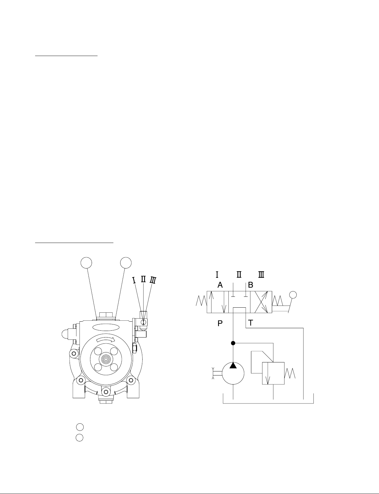
6. HYDRAULIC SYSTEM (DUMPING)
Hydraulic pump
Hydraulic pump : K82R
(Part no 89956-1559-0)
Discharge volume : 3cc/rev
Revolution : 500 ~ 2000rpm
2
Relief valve set pressure : 140+5/kgf/cm
(at 1800rpm)
Tank capacity : 1.6 l
Pulley size (pump) : Dia 101.6mm
(Part no 89956-1298-0)
Pulley size (engine) : Dia 76.2mm
(Part no 89920-1157-0)
(13.7+0.5MPa)
Flow of hydraulic oil
A
B
A Pull-Down port
B
Push-up port
K70E-U002
11
Page 14
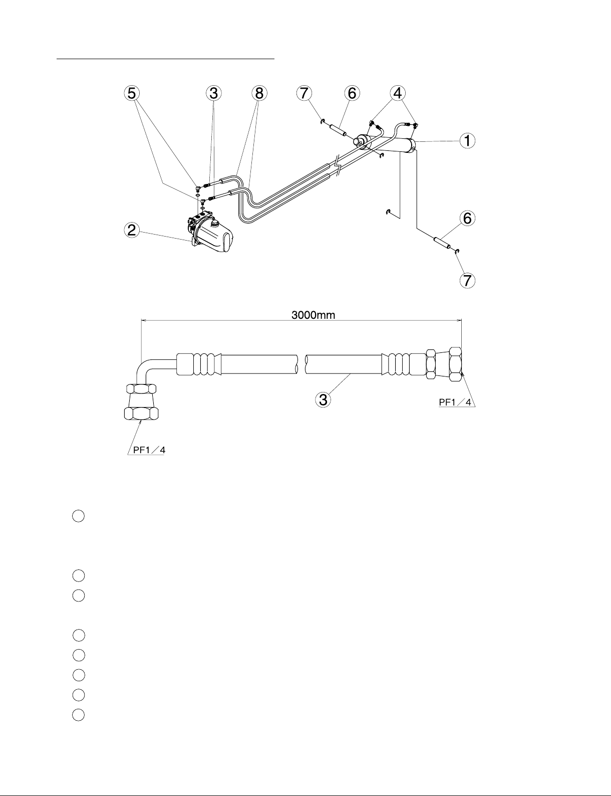
Hydraulic hose / Hydraulic cylinder
1 : Hydraulic cylinder (Part no 89950-1154-0 / 1 pce)
2
Pressure : 170kgf/cm
(16.7MPa)
Stroke : 300mm
: Hydraulic pump (Part no 89956-1559-0 / 1 pce)
2
: Hydraulic hose (Part no 89957-1233-0 / 2 pcs)
3
Length : 3000mm
: Elbow (Part no 89910-1188-0 / 2 pcs)
4
: Hose adapter with O-ring (Part no 89910-1189-0 / 2 pcs)
5
: Cylinder pin (Part no 89954-1159-0 / 2 pce)
6
: Cir-clip (E) (Part no 04613-00150 / 4 pcs)
7
: Vinyl tube (Part no 89957-1234-0 / 2 pcs)
8
12
K10H-D002
Page 15
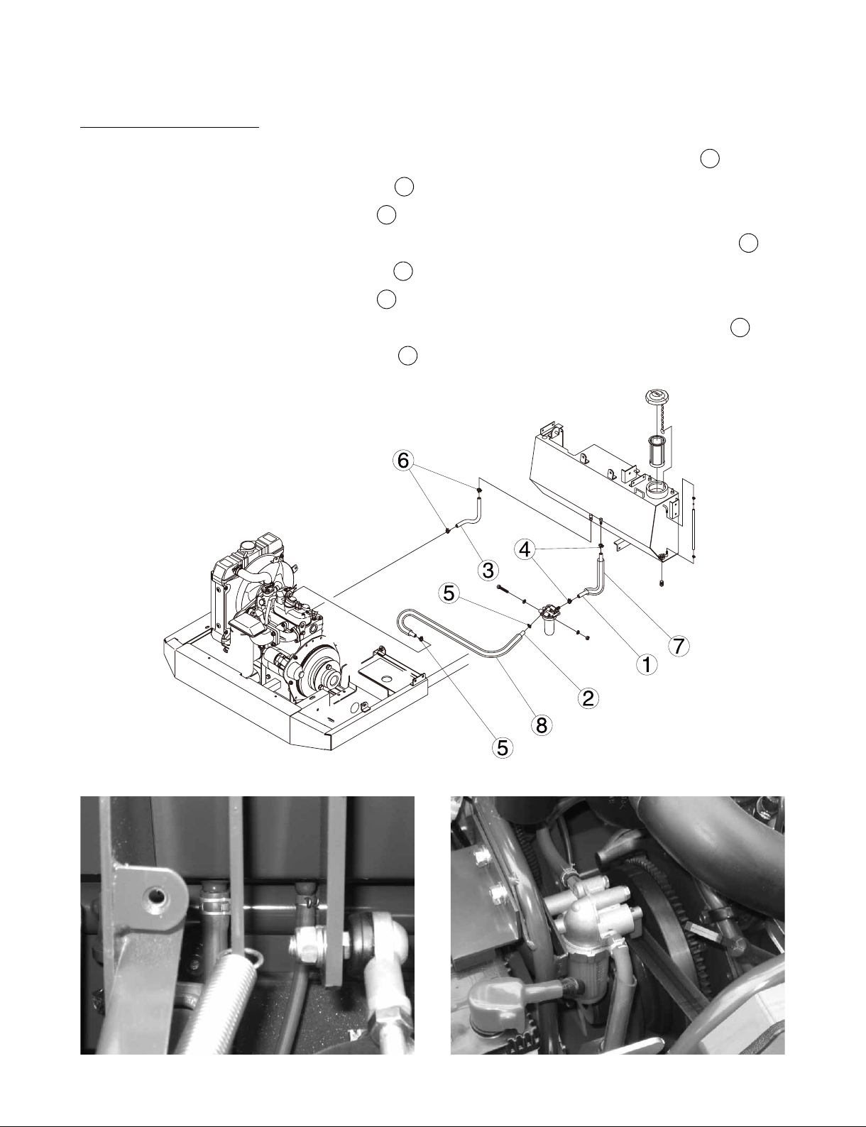
7. FUEL SYSTEM
Fuel tank / Fuel hose
1) Fuel hose (Fuel tank ~ Fuel lter) Size : L : 1400mm x 1 pce / 09661-7140-0 / 1
Clip x 2pcs - Part no 14911-4275-0 / 4
Tube x 1pce - part no 89920-1265-0 / 7
2) Fuel hose (Fuel lter ~ Injection pump) Size : L : 750mm x 1 pce / 09661-7075-0 /
Clip x 2pcs - Part no 14911-4275-0 / 5
Tube x 1pce - part no 89920-1264-0 / 8
3) Fuel hose (Nozzle holder ~ Fuel tank) Size : L : 1150mm x 1 pce / 09661-4115-0 / 3
Clip x 2pcs - part no 14971-4275-0 /
6
2
K10H-D003
13
Page 16
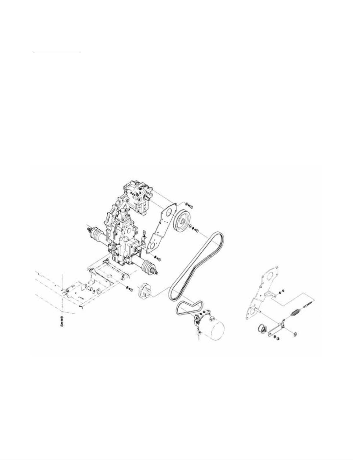
8. V-BELT
Size of V-belt
1) V-belt (Engine pulley ~ HST pulley)
Size : SC64 (Cog belt) x 1 pce / Part no 89920-1170-0
2) V-belt (Engine pulley ~ Hydraulic pump pulley)
Size : SB29 x 1 pce / Part no 89920-1175-0
3) Engine pulley
Part no 89920-1157-0
4) HST pulley
Part no 89920-1165-0
14
Page 17
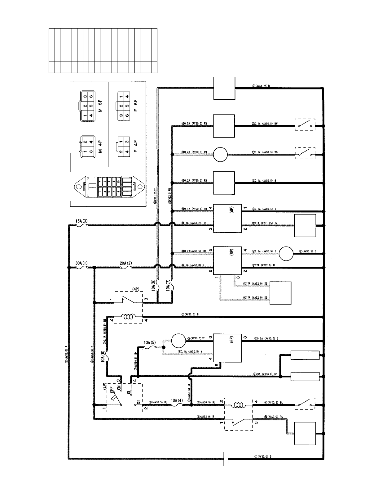
Cord color
B Black
Br Brown
G Green
L Blue
P Pink
R Red
SB Sky blue
W White
Y Yellow
BL Black / Blue
BW Black / White
GB Green / Black
LB Blue / Black
PB Pink / Black
RW Red / White
WB Red / White
YB Yellow / Black
BR Black / Red
Starter
Safety switch
Glow plug
Alternator
ⒶⒷⒸⒹⒺ
Regulator
Alarm lamp “Battery
charge”
Solenoid timer
Solenoid
Ⓕ
ⒼⒽⒾ
Ⓝ
Ⓛ
Ⓙ
Hour meter
Alarm lamp “Engine
oil pressure”
Oil switch
Horn
Ⓙ
ⓀⓁⓂⓃⓄⓅⓆ
Horn switch
Electrical socket
Glow timer
Indicator lamp
“Glow”
Relay
Ⓜ
Ⓚ
Key switch
Fuse arrangement
Connector terminal
arrangement
ⓇⓈⓉ
Ⓢ Ⓣ
Ⓘ
Ⓖ
Ⓗ
Ⓕ
Ⓔ
Ⓠ
Ⓓ
Ⓟ
Ⓞ
Ⓡ
9. WIRING DIAGRAM
Ⓠ
Ⓐ Ⓑ Ⓒ Ⓒ
15
Page 18

SERVICING
1. TIGHTENING TORQUE
2. OILS AND FUEL
3. GREASING
4. CAUTION FOR DISASSEMBLING AND REASSEMBLING
5. ADJUSTMENT OF COMPONENT PARTS
6. TESTING OF PRESSURE (HST)
7. REPLACEMENT OF WEAR OUT PARTS
8. TROUBLESHOOTING AND COUNTERMEASURES
9. MAINTENANCE INTERVALS
16
Page 19
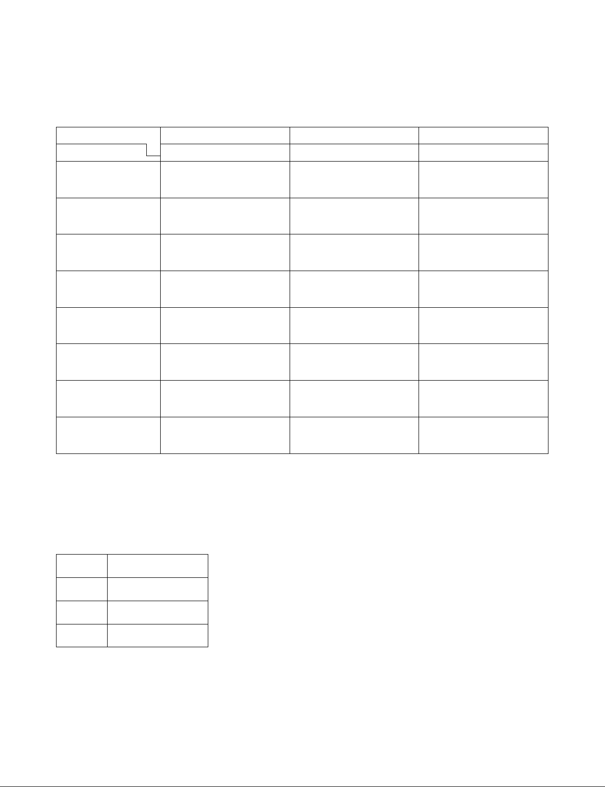
1. TIGHTENING TORQUE
1) GENERAL BOLTS AND NUTS
Bolt torque
Material Grade Standard Bolt Special Bolt Special Bolt
Nominal Dia.
M6
M8
M10
M12
M14
M16
M18
M20
SS41, S20C S43C, S487C (Rened) SCR3, SCM3 (Rened)
7.8 - 9.3 N.m
0.80 - 0.95 kgf-m
5.8 - 6.9 lb.ft.
17.7 - 20.6 N.m
1.80 - 2.10 kgf-m
13.0 - 15.2 lb.ft.
39.2 - 45.1 N.m
4.00 - 4.60 kgf-m
28.9 - 33.3 lb.ft.
62.8 - 72.6 N.m
6.40 - 7.40 kgf-m
46.3 - 53.5 lb.ft.
107.9 - 125.5 N.m
11.00 - 12.80 kgf-m
79.6 - 92.6 lb.ft.
166.7 - 191.2 N.m
17.00 - 19.50 kgf-m
123.0 - 141.0 lb.ft.
245.2 - 284.4 N.m
25.00 - 29.00 kgf-m
180.0 - 209.8 lb.ft.
333.4 - 392.2 N.m
34.00 - 40.00 kgf-m
245.9 - 289.3 lb.ft.
9.8 - 11.3 N.m
1.00 - 1.15 kgf-m
7.2 - 8.3 lb.ft.
23.5 - 27.5 N.m
2.40 - 2.80 kgf-m
17.4 - 20.3 lb.ft.
48.0 - 55.9 N.m
4.90 - 5.70 kgf-m
35.4 - 41.2 lb.ft.
77.5 - 90.2 N.m
7.90 - 9.20 kgf-m
57.1 - 66.5 lb.ft.
123.6 - 147.1 N.m
12.60 - 15.00 kgf-m
91.1 - 108.5 lb.ft.
196.1 - 225.5 N.m
20.00 - 23.00 kgf-m
144.7 - 166.4 lb.ft.
274.6 - 318.7 N.m
28.00 - 32.50 kgf-m
202.5 - 235.1 lb.ft.
367.7 - 431.5 N.m
37.50 - 44.00 kgf-m
271.2 - 318.2 lb.ft.
10.50 - 12.00 kgf-m
17.00 - 20.00 kgf-m
26.50 - 31.00 kgf-m
35.00 - 41.00 kgf-m
50.00 - 58.00 kgf-m
12.3 - 14.2 N.m
1.25 - 1.45 kgf-m
9.0 - 10.5 lb.ft.
29.4 - 34.3 N.m
3.00 - 3.50 kgf-m
21.7 - 25.3 lb.ft.
60.8 - 70.6 N.m
6.20 - 7.20 kgf-m
44.8 - 52.1 lb.ft.
103.0 - 117.7 N.m
75.9 - 86.8 lb.ft.
166.7 - 196.1 N.m
123.0 - 144.7 lb.ft.
259.9 - 304.0 N.m
191.7 - 224.2 lb.ft.
343.2 - 402.0 N.m
253.2 - 296.5 lb.ft.
490.3 - 568.7 N.m
361.6 - 419.5 lb.ft.
Bolt material grades are shown
by numbers punched on the bolt
heads. Prior to tightening, be
sure to check out the numbers as
shown below.
Punched
Number
None
7
9
Bolt Material
Grade
Standard Bolts SS41,
S20C
Standard Bolts SS43,
S48C (Rened)
Special Bolts SCR3,
SCM3 (Rened)
17
Page 20
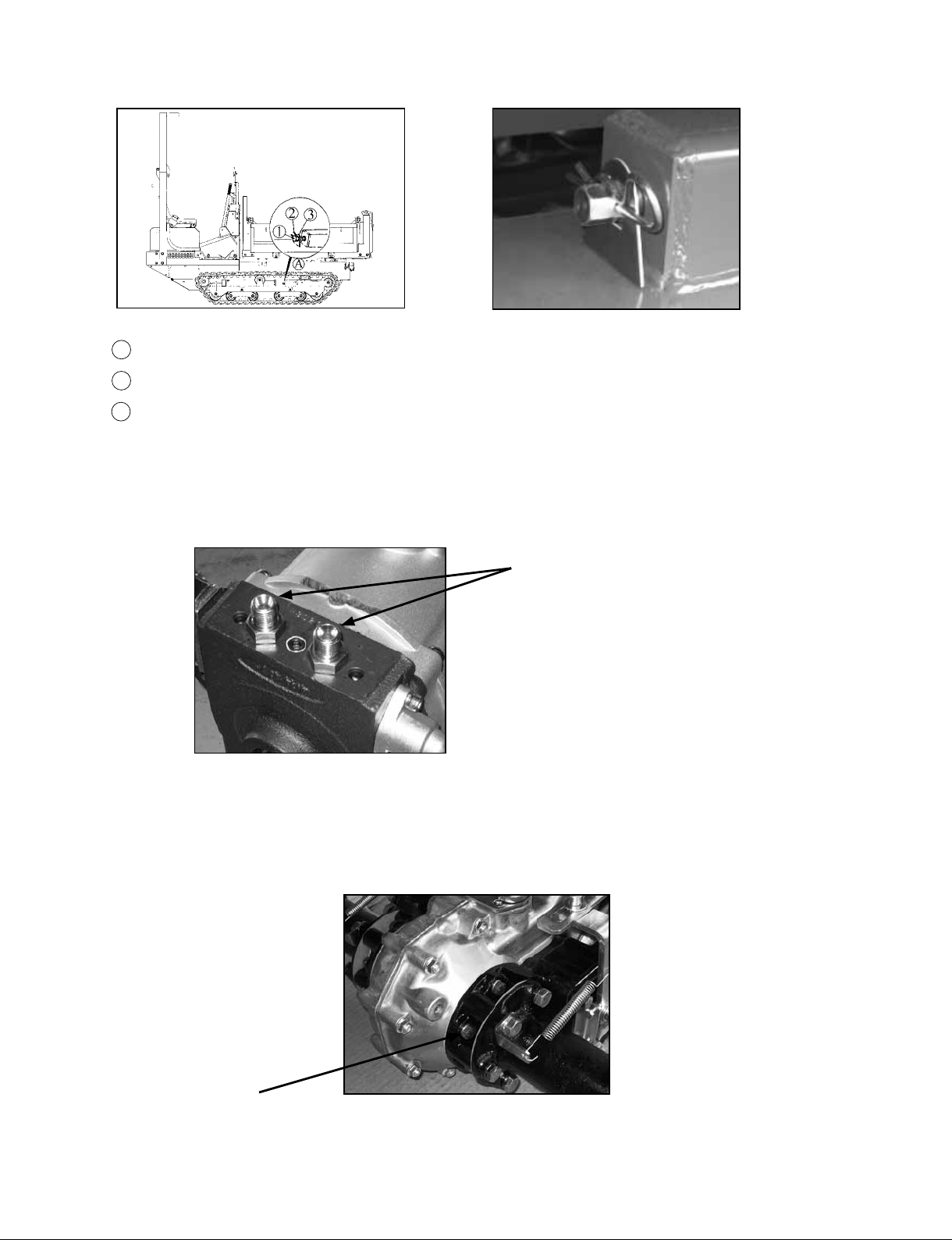
2) Crawler adjusting bolt : 215 ~ 225kgf . cm (21.1N . m ~ 22.1N . m)
1 : Adjusting bolt (Part no 89954-1205-0)
: Snap pin (Part no 89910-1289-0)
2
: Stopper (Part no 89950-1372-0)
3
3) Hose adapter for hydraulic pump : 200 ~ 240kgf . cm (19.6N . m~23.5N . m)
4) Transmission
4-1 Brake case [BOLT] : 220 ~ 280kgf . cm (21.6N . m ~ 27.4N . m)
18
Page 21
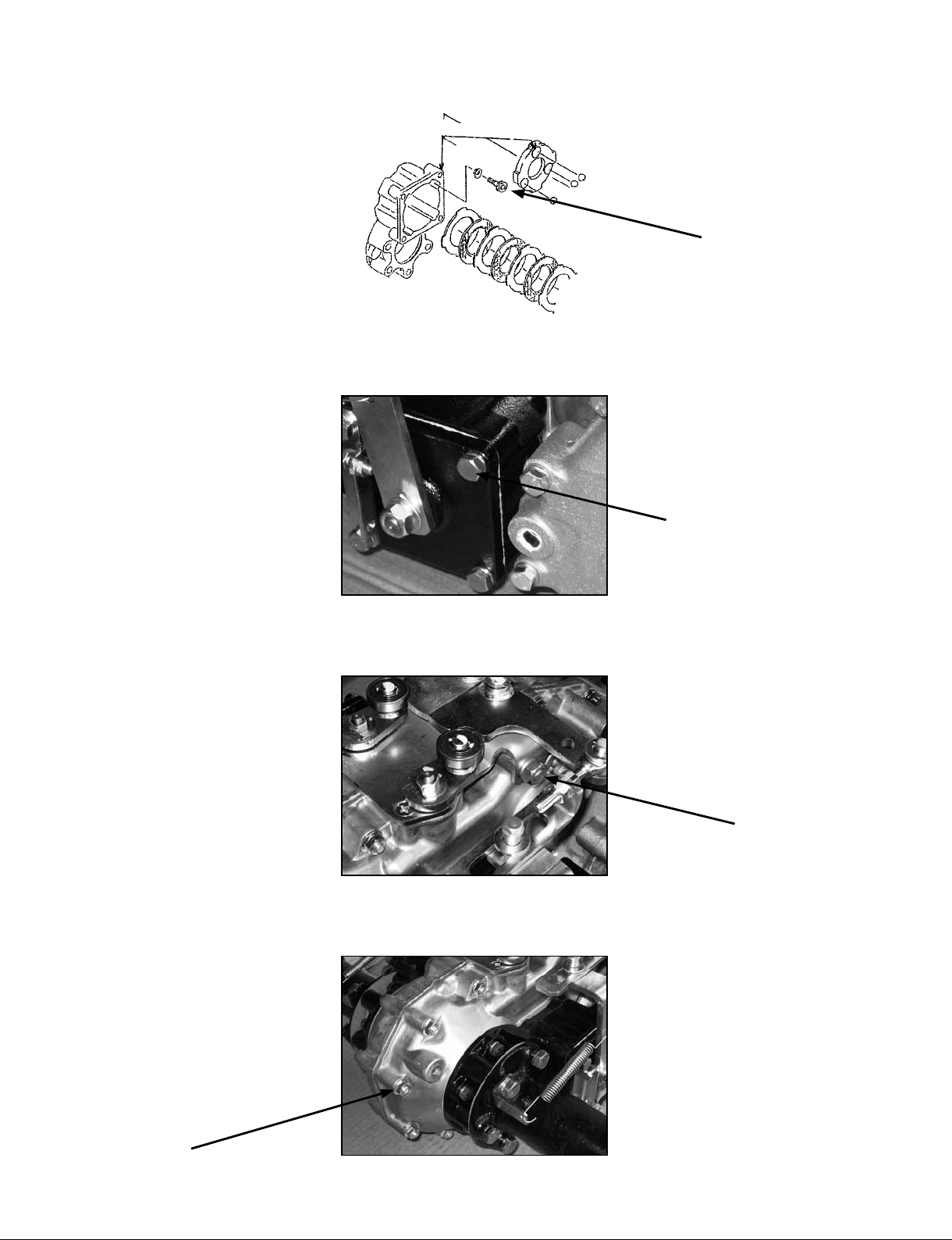
4-2 Brake case [BOLT] : 300 ~ 350kgf . cm (29.4N . m ~ 34.3N . m)
K10H-D013
4-3 Brake case cover [BOLT] : 220 ~ 280kgf . cm (21.6N . m ~ 27.4N . m)
4-4 Transmission case [NUT] : 400 ~ 450kgf . cm (39.2N . m ~ 44.1N . m)
4-5 Transmission case [NUT] : 120 ~ 170kgf . cm (11.8N . m ~ 16.7N . m)
19
Page 22
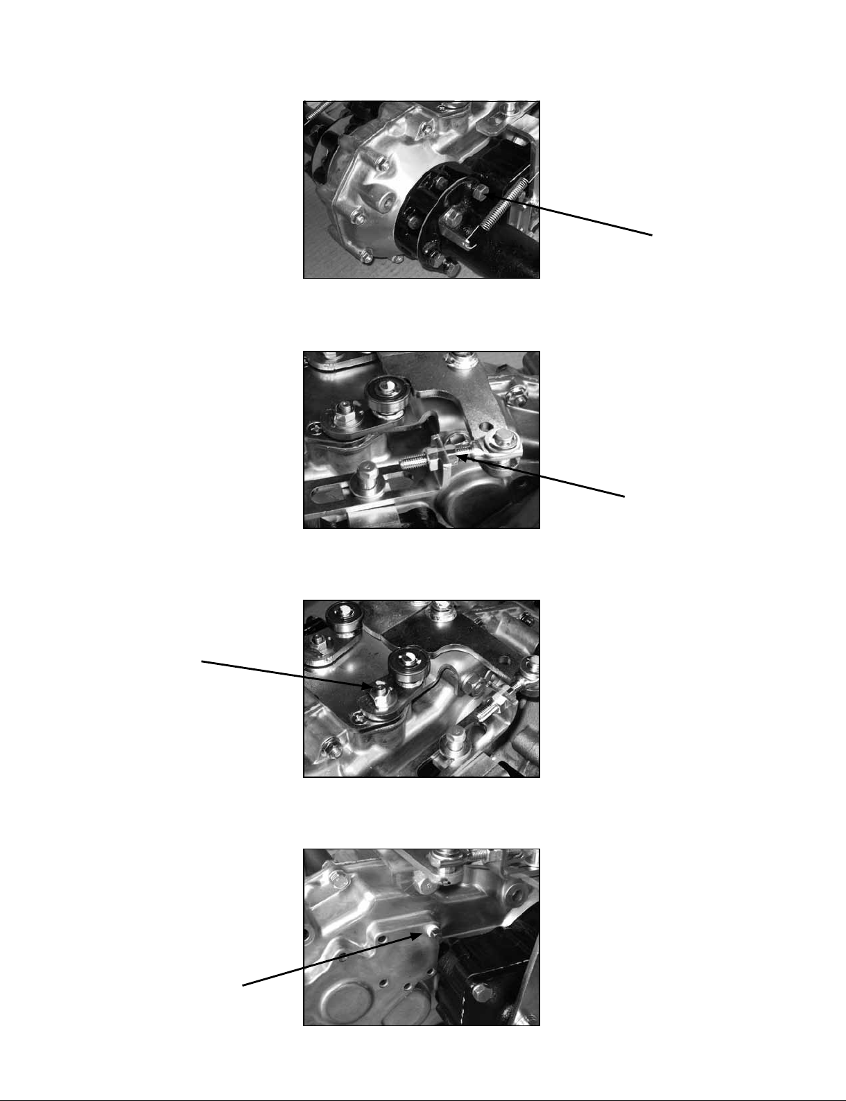
4-6 Axle pipe [BOLT] : 400 ~ 450kgf . cm (39.2N . m ~ 44.1N . m)
4-7 Brake joint [NUT] : 120 ~ 170kgf . cm (11.8N . m ~ 16.7N . m)
4-8 Shift lever comp [NUT] : 120 ~ 170kgf . cm (11.8N . m ~ 16.7N . m)
4-9 Plug [PT1/8] : 40 ~ 50kgf . cm (3.9N . m ~ 4.9N . m)
20
Page 23
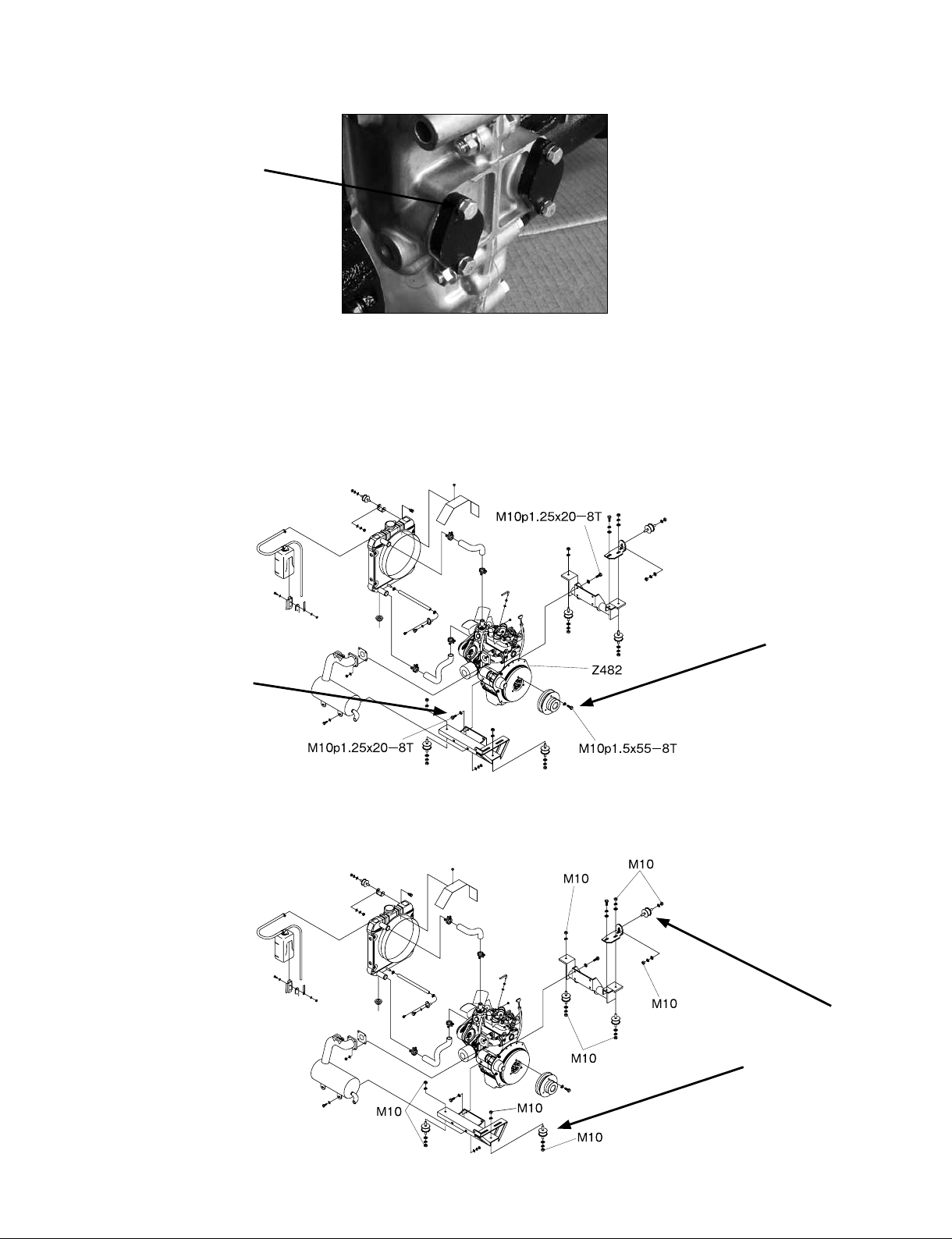
4-10 Shifter support [BOLT] : 100 ~ 120kgf . cm (9.8N . m ~ 11.8N . m)
5) ENGINE PULLEY MOUTING BOLT : 440 ~ 480kgf . cm (43.2N . m ~ 47.0N . m)
(M10 x 55)
6) ENGINE MOUTING BOLT : 460 ~ 500kgf . cm (45.1N . m ~ 49.1N . m)
(M10 x 25)
7) CUSHION : 445 ~ 455kgf . cm (43.7N . m ~ 44.6N . m)
K10H-D005
K10H-D006
21
Page 24
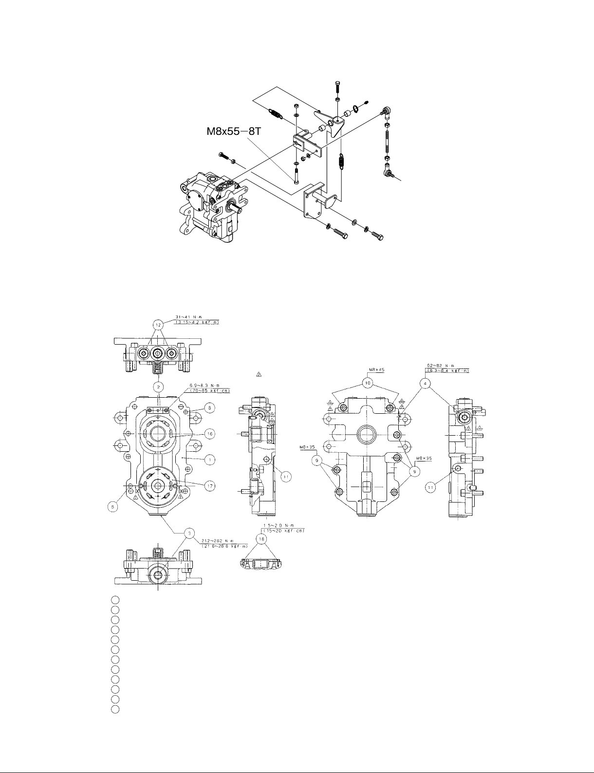
8) BOLT FOR HST NEUTRAL LEVER : 280 ~ 300kgf . cm (27.5N . m ~ 29.4N . m)
(M8 x 55)
K10H-D007
9) HST
9-1 Cover
22
1 Cover
Relief valve (Low pressure)
2
Relief valve (High pressure)
3
Neutral valve
4
Pin
8
Bolt
9
10
Bolt
11
Plug
12
Plug
16
Control plate (Pump)
17
Control plate (Motor)
18
Screw
(Apply the screw locking bond to screws)
Page 25
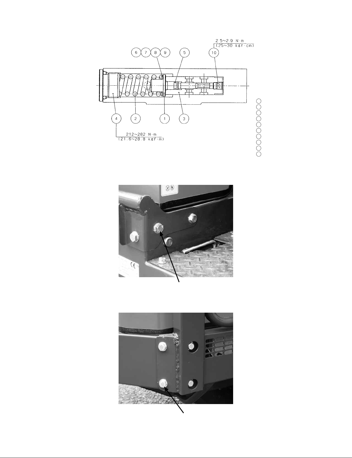
9-2 Relief valve [High pressure]
10) ROPS
[M10 x 20 / 10.9T - 6 pcs, M12 x 20 / 10.9T - 8 pcs]
1 Poppet
Spring
2
Barrel
3
Plug
4
O-ring
5
Shim 13.5 x 22 x 1.0
6
Shim 13.5 x 22 x 0.7
7
Shim 13.5 x 22 x 0.5
8
Shim 13.5 x 22 x 0.3
9
10
Plug
[M10 x 20 / 10.9T - 6 pcs / Approx. 640kgf . cm (62.6N . m)]
[M12 x 20 / 10.9T - 8 pcs / Approx. 1100kgf . cm (109N . m)]
23
Page 26
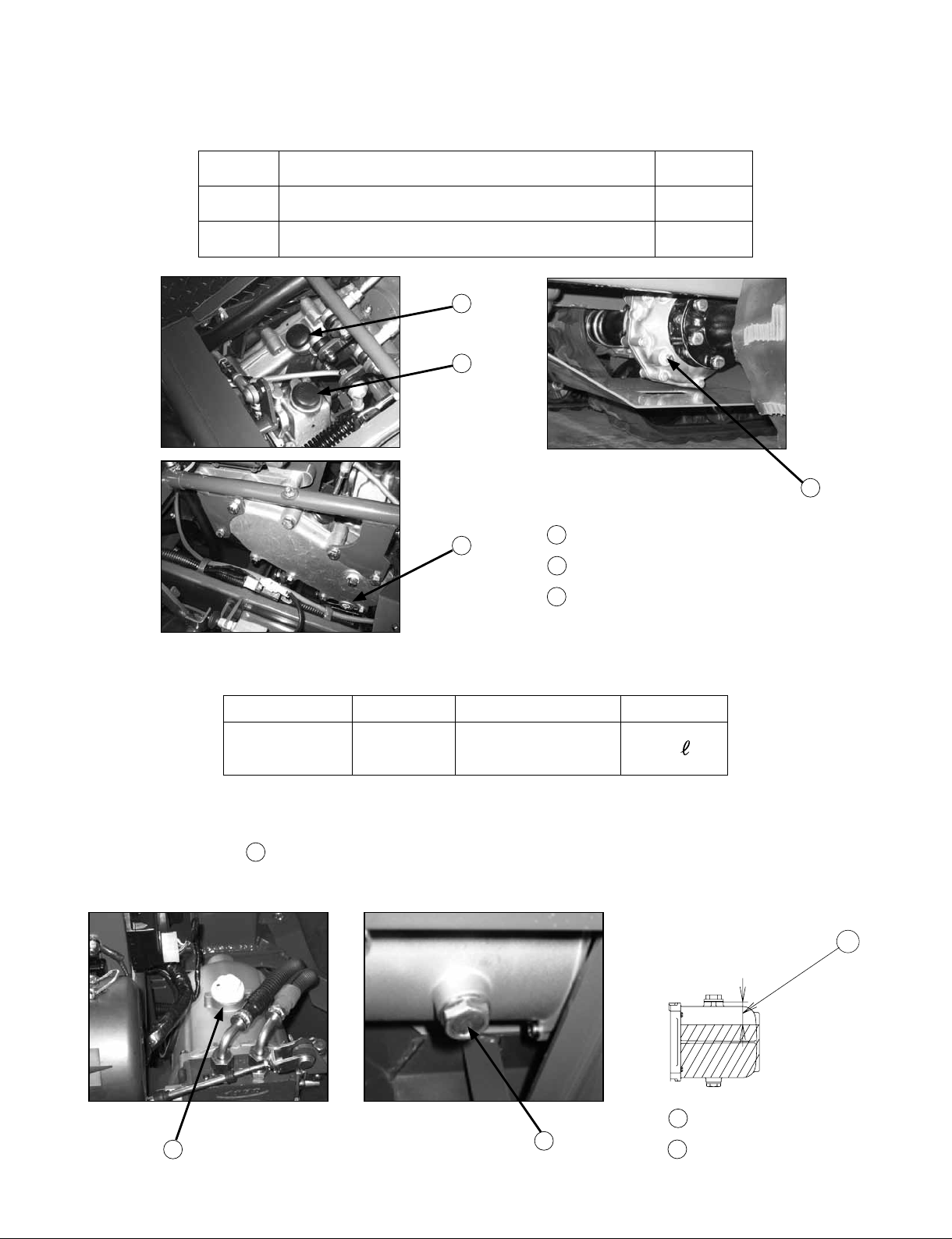
2. OILS AND FUEL
1) TRANSMISSION OIL
Main Automatic transmission uid (ATF) [DEXRON] 3.1L
Sub Automatic transmission uid (ATF) [DEXRON] 0.45L
Type of oil Quantity
2
1
3
3
1 Oil port (main)
Oil port (sub)
2
Drain plug
3
2) HYDRAULIC PUMP OIL
Type of oil Viscosity Quantity
Hydraulic oil ISO46
NOTE
Total capacity of hydraulic pump oil with new cylinder and hoses : Approx. 1.9L.
Proper oil level A
: Approx. 50mm / distance from oil port
(Hydraulic cylinder completed contacted)
Shell Tellus T46 or
equivalent oil
1.5
A
24
K70E-U007
4 Oil port
4
5
Drain plug
5
Page 27
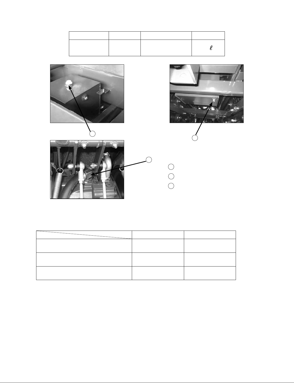
3) HST OIL
Type of oil Viscosity Quantity
Hydraulic oil ISO46
5
Shell Tellus T46 or
equivalent oil
7
5 Tank cap
Drain plug
6
13
6
Drain port
7
IMPORTANT
If HST oil is lled to HST unit rst, add the HST oil (approx. 1.5L)
through drain port of HST unit.
Shell Mobil
Transmission oil
(Automatic transmission uid / ATF)
HST oil
(Hydraulic oil / ISO : 46)
Hydraulic pump oil
(Hydraulic oil / ISO : 46)
Super ATF Mobil ATF
Shell Tellus T46
Shell Tellus T46
Mobil DTE-Oil 15
Mobil DTE-Oil 15
New machine is used Shell oil.
25
Page 28

4) ENGINE OIL
[Engine oil quantity : 2.55 L]
Temperature Type of oil
Above 25˚C
0˚C to 25˚C
Below 0˚C
NOTE
Engine Oil :
• Refer to the following table for the suitable American Petroleum Institute (API)
classication of engine oil according to the engine type (with internal EGR, external EGR
or non-EGR) and the Fuel Type Used :
(Low Sulfur, Ultra Low Sulfur or High Sulfur Fuels).
Fuel Type
Engines with non-EGR
Engines with internal EGR
SAE30 or SAE10W-30
SAE10W-40
SAE20 or SAE10W-30
SAE10W-40
SAE10 or SAE10W-30
SAE10W-40
Engine oil classication (API classication)
Engines with external EGR
High Sulfur Fuel
[0.05 % (500 ppm) ≤
Sulfur Content <
0.50 % (5000 ppm)]
Low Sulfur Fuel
[Sulfur Content <
0.05 % (500 ppm)] or
Ultra Low Sulfur Fuel
[Sulfur Content <
0.0015 % (15 ppm)]
CF
(If the "CF-4, CG-4, CH-4, or CI-4" engine
oil is used with a high-sulfur fuel, change
the engine oil at shorter intervals.
(approximately half))
CF, CF-4, CG-4, CH-4 or CI-4
-
CF or CI-4
(Class CF-4, CG-4 and CH-4
engine oils
cannot be used on EGR type
engines.)
EGR : Exhaust Gas Re-circulation
W1024941
• CJ-4 classication oil is intended for use in engines equipped with DPF (Diesel Particulate
Filter) and is
Not Recommended for use in Kubota E3 specication engines.
• Oil used in the engine should have API classication and Proper SAE Engine Oil Viscosity
according to the ambient temperatures where the engine is operated.
• With strict emission control regulations now in effect, the CF-4 and CG-4 engine oils
have been developed for use with low sulfur fuels, for On-Highway vehicle engines.
When a Non-Road engine runs on high sulfur fuel, it is advisable to use a "CF or better"
26
Page 29
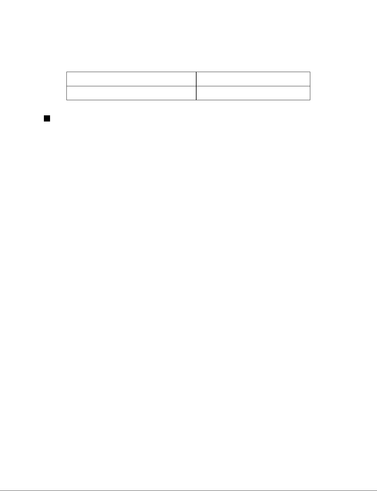
classication engine oil with a high Total Base Number
(a minimum TBN of 10 is recommended).
5) FUEL
Type Capatity
over -5˚, use No.2-D diesel fuel 14.8 L
NOTE
Fuel :
• Cetane Rating : The minimum recommended Fuel Cetane Rating is 45. A cetane rating
greater than 50 ispreferred, especially for ambient temperatures below −20 °C (−4 °F) or
elevations above 1500 m (5000 ft).
• Diesel Fuel Specication Type and Sulfur Content % (ppm) used, must be compliant with
all applicable emission regulations for the area in which the engine is operated.
• Use of diesel fuel with sulfur content less than 0.10 % (1000 ppm) is strongly
recommended.
• If high-sulfur fuel (sulfur content 0.50 % (5000 ppm) to 1.0 % (10000 ppm)) is used as a
diesel fuel, change the engine oil and oil lter at shorter intervals. (approximately half)
• DO NOT USE Fuels that have sulfur content greater than 1.0 % (10000 ppm).
• Diesel fuels specied to EN 590 or ASTM D975 are recommended.
• No.2-D is a distillate fuel of lower volatility for engines in industrial and heavy mobile
service. (SAE J313 JUN87)
• Since KUBOTA diesel engines of less than 56 kW (75 hp) utilize EPA Tier 4 and Interim
Tier 4 standards, the use of low sulfur fuel or ultra low sulfur fuel is mandatory for these
engines, when operated in US EPA regulated areas. Therefore, please use No.2-D S500 or
S15 diesel fuel as an alternative to No.2-D, and use No.1-D S500 or S15 diesel fuel as an
alternative to No.1-D for ambient temperatures below −10 °C (14 °F).
1) SAE : Society of Automotive Engineers
2) EN : European Norm
3) ASTM : American Society of Testing and Materials
4) US EPA : United States Environmental Protection Agency
5) No.1-D or No.2-D, S500 : Low Sulfur Diesel (LSD) less than 500 ppm or 0.05 wt.%
No.1-D or No.2-D, S15 : Ultra Low Sulfur Diesel (ULSD) 15 ppm or 0.0015 wt.%
27
Page 30

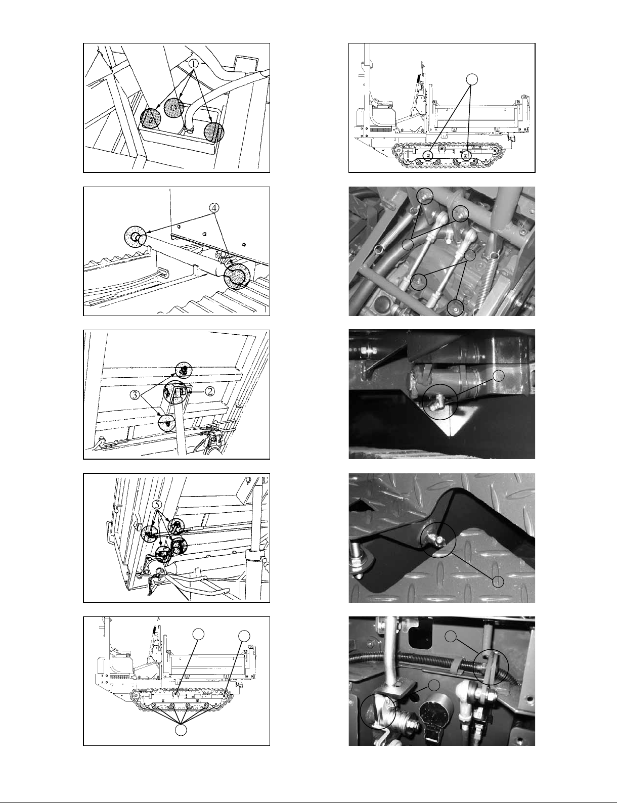
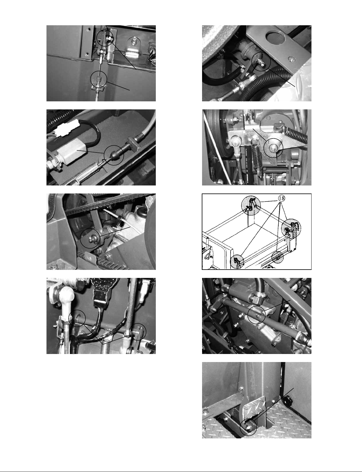
3. GREASING
• Greasing
CAUTION
To avoid personal injury:
• First stop the engine.
Apply a small amount of multipurpose grease or oil to the following points every 50 hours.
1 Cylinder lower (oil)
2
Cylinder upper (oil)
3
Cylinder upper (grease)
4
Deck body support fulcrum (grease)
5
Opening/closing kit (right & left) (oil)
6
Lower roller (grease)
7
Upper roller (grease)
8
Idler (grease)
9
Bogie roller (grease)
1
0 Wire (Brake, accelerator etc) (oil)
1
1 Steering lever (grease)
12
Dump lever joint (oil)
13
Brake pedal (grease)
14
Accelerator lever (oil)
15
Drive pedal shaft (grease)
16
Main clutch tension arm (grease)
17
Dump lever (grease)
18
Lever, dump support (grease)
19
Link arm, drive pedal (grease)
2
0 Speed change lever (grease)
2
1 Neutral plate (grease)
2
2 Parking brake lever (oil)
28
Page 31
11
9
11
13
15
7
8
17
20
6
29
Page 32
⑭
⑩
⑩
⑯
21
○
⑲
30
⑫
⑳
○
22
Page 33
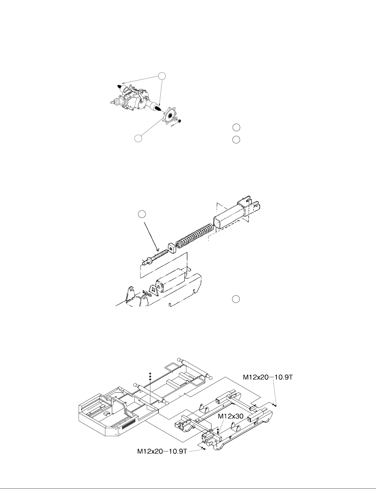
4. CAUTION FOR DISASSEMBLING AND REASSEMBLING
1
1) SPROCKET
Before tting the sprocket to shaft of transmission, apply the grease to the spline of shaft.
1
Grease
2
K70E-U008
Sprocket
2
2) ADJUSTING BOLT FOR CRAWLER
Apply the grease to adjusting bolt to prevent the rust of bolt and nut.
3
3
Grease
3) BOLTS FOR FRAME (UPPER / UNDER)
Apply the screw locking bond to bolts.
K10H-D008
31
Page 34
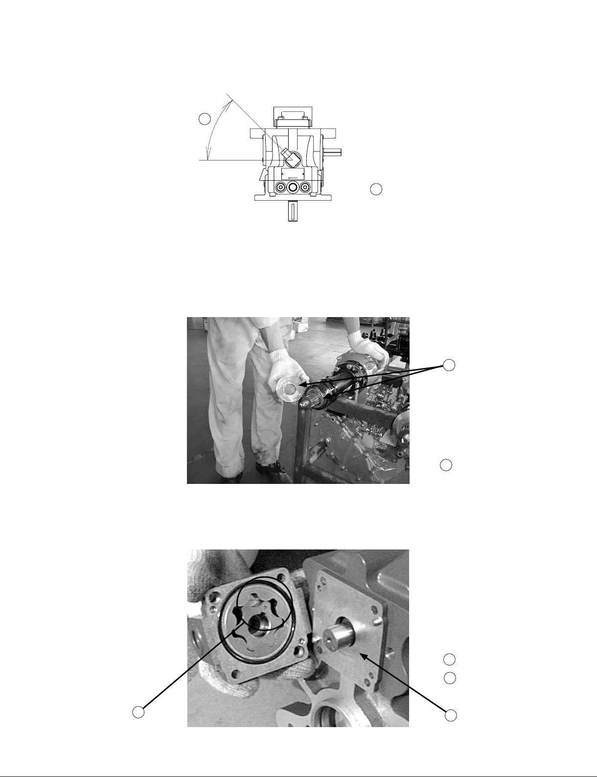
4) ANGLE OF DRAIN PORT (HST UNIT)
When remove the hose from drain port for HST unit, check the angle of drain port.
1
1 About 45˚
K10H-D009
5) DUST COVER FOR TRANSMISSION (FINAL SHAFT)
Before tting the sprocket to nal shaft of transmission, apply the grease to the surface of oil seal
and dust cover.
6) CHARGE PUMP (HST)
Face the mark toward plate side.
2
Grease
2
32
Marks
3
Plate
4
3
4
Page 35
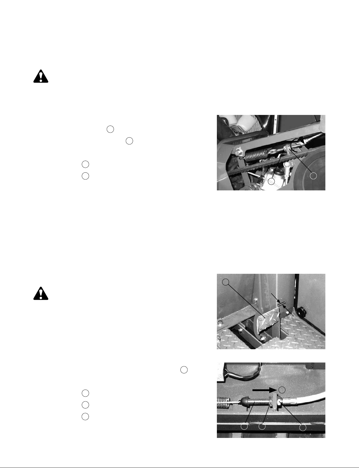
5. ADJUSTMENT OF COMPONENT PARTS
5-1 MAIN CLUTCH ADJUSTMENT
• Check and adjustment of V-belt tension (main clutch)
CAUTION
To avoid personal injury:
• First stop the engine.
• After servicing, make sure the function of main clutch.
1. When the main clutch (V-belts) slips.
1) Loosen the lock nut
by tightening the adjust nut
1 , then adjust the V-belt tension
2 .
2) After the adjustment, tighten up the lock nut.
Adjust nut
1
Lock nut
2
Reference for proper belt tension
1) Depress the center of V-belt with thumb pressure.
[8 to 10 mm / 5 kgf]
IMPORTANT
• After the adjustment, tighten up the lock nuts
5-2 BRAKE PEDAL ADJUSTMENT
• Check and adjustment of brake pedal
CAUTION
To avoid personal injury:
2
1
1
• First stop the engine.
• Be sure to check the braking force of parking
brake after adjustment.
1. Check the brake pedal free travel.
2. If the brake pedal free travel exceeds the limit, loosen
the lock nuts and move the adjust bolt toward
A .
3. After adjustment, tighten up the lock nut.
Brake pedal
1
Adjust bolt
2
Lock nut
3
[Proper brake pedal free travel/1mm]
2 3
A
3
33
Page 36
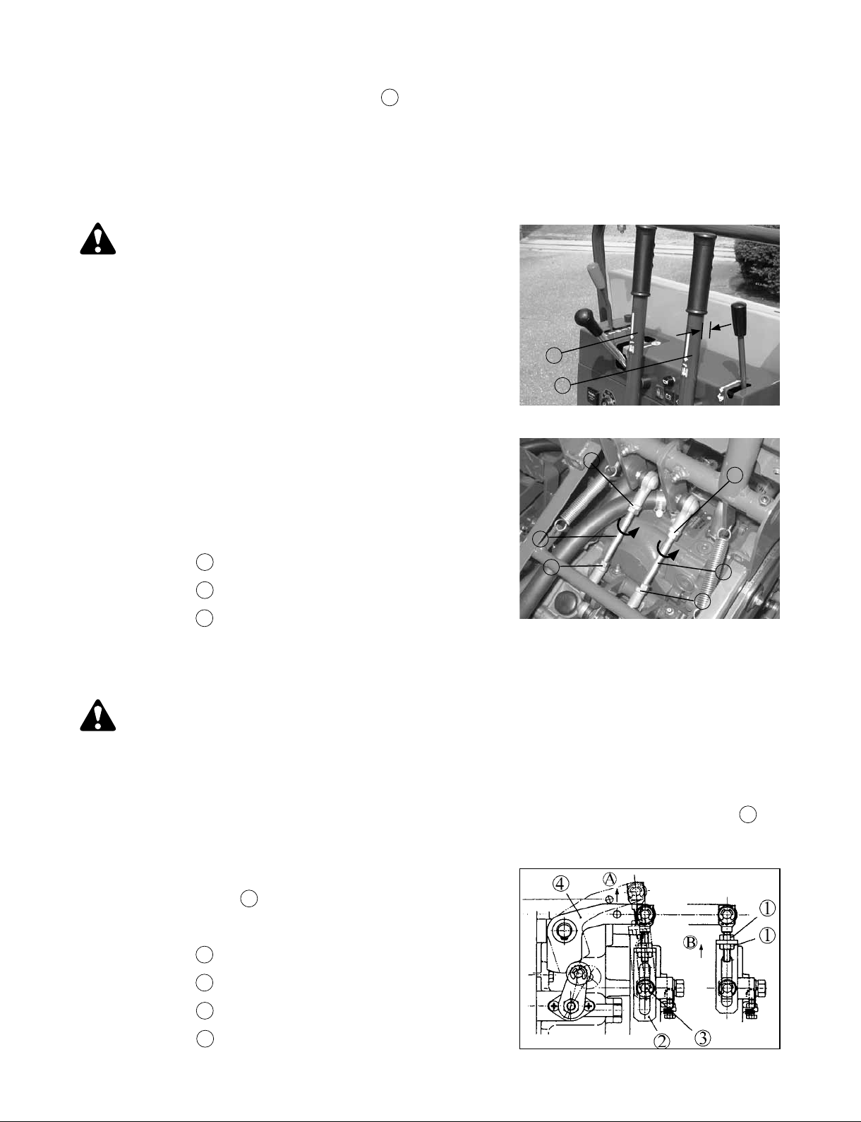
IMPORTANT
• If you turn the turn buckle toward A
too much, the brake is applied at all times.
This will cause the damage of transmission.
5-3 STEERING LEVER ADJUSTMENT
• Check and adjustment of steering lever
CAUTION
To avoid personal injury:
• First stop the engine.
• After servicing, make sure the function of
steering lever.
If it is difcult to disengage or engage the steering clutch,
check the following below.
1. Check the steering lever free travel.
2. If steering lever free travel exceeds the limit, loosen the
lock nuts and adjust the rod.
3. After the adjustment, tighten up the lock nut.
1
1
3
3
[Proper steering lever free travel / 3mm]
Steering lever
1
Rod
2
Lock nut
3
2
3
2
3
• Check and adjustment of steering brake
CAUTION
To avoid personal injury:
• First stop the engine.
• Be sure to check the braking force after adjustment.
1. When the steering brake is too weak, loose the lock nuts and move the adjust plate toward B
~ 6mm)
2. Check that adjust plate contact the brake lever, when move
the Lever C toward A
approx. 17 mm
.
3. After the adjustment, tighten up the lock nuts
.
(4
34
Lock nut
1
Adjust plate
2
Brake lever
3
Lever C
4
Page 37
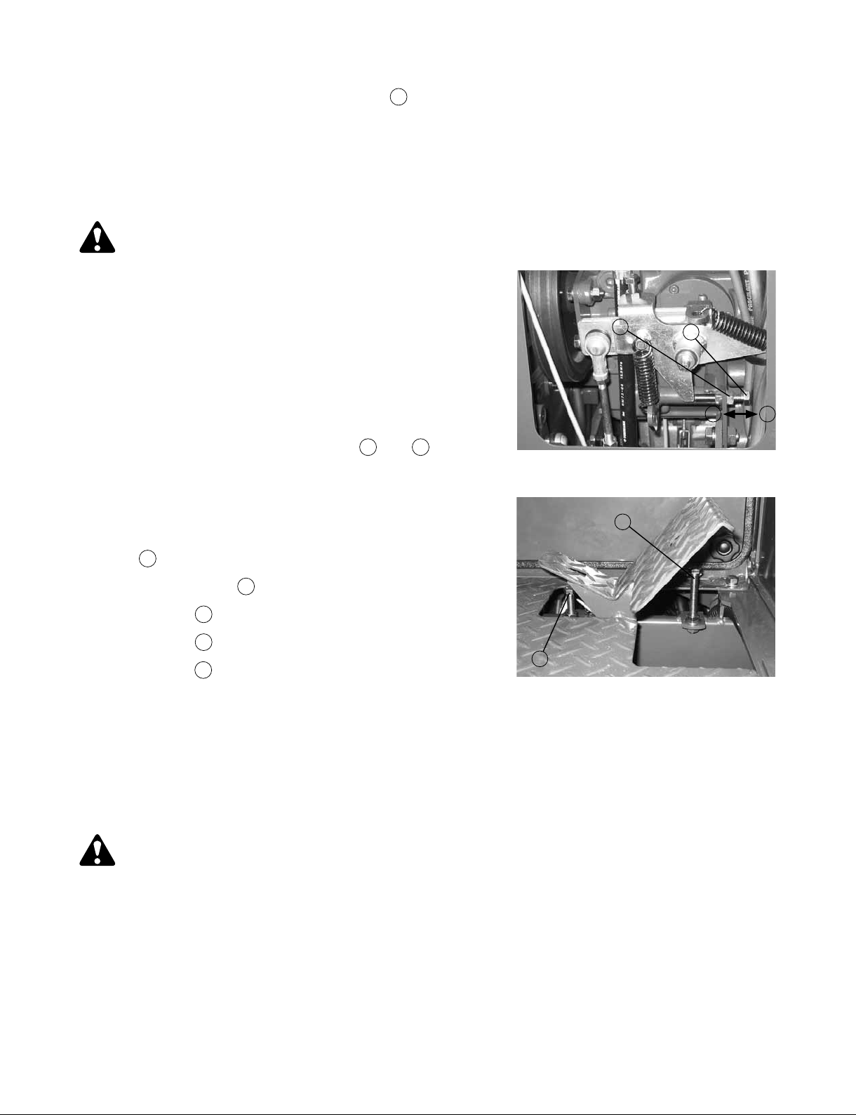
IMPORTANT
• If you move the adjust plate toward B
too much, the steering brake is applied at all times.
This will cause the damage of transmission.
5-4 NEUTRAL SYSTEM ADJUSTMENT
• Check and adjustment of drive pedal
CAUTION
To avoid personal injury:
• First stop the engine.
• After servicing, make sure the function of
drive pedal.
If abnormal operation (the machine moves at a very slow
speed, even if remove the foot from drive pedal)
is found, check and adjust the following below.
1) Move the adjusting bolt toward A
machine does not move.
2) After adjustment lock the the adjusting bolt.
When the machine move forward, move the adjusting bolt
or B until the
2
3
1
AB
toward A
adjusting bolt toward B
When the machine move backward, move the
.
Adjusting bolt
1
Lock nut
2
Drive pedal locking bolt
3
3
IMPORTANT
• Do not adjust the height of the drive pedal locking bolts.
5-5 BELT TENSION ADJUSTMENT
• Check and adjustment of V-belt tension (hydraulic pump)
CAUTION
To avoid personal injury:
• First stop the engine.
1. Loosen the V-belt tension by loosening adjusting nut and lock nut for tension bolt after a little
loosening two of bolts for hydraulic pump.
2. Adjust the V-belt tension by tightening adjusting nut.
3. After the adjustment, tighten up the lock nut and two of bolts for hydraulic pump. Reference
for proper belt tension.
35
Page 38
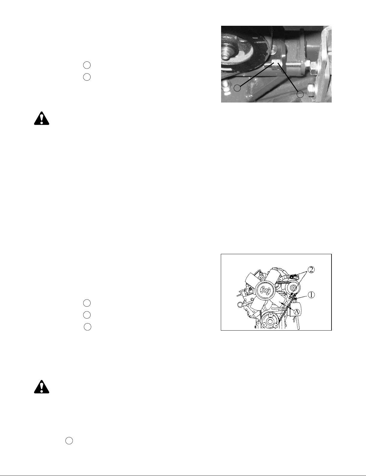
Depress the center of V-belt with thumb pressure.
Displacement at center of belt / load to belt.
[8 to 10 mm / 5 kgf]
Lock nut
1
Adjust nut
2
1
• Check and adjustment of fan belt tension
CAUTION
To avoid personal injury:
1. Be sure to stop the engine and remove the key before checking the belt tension.
2. Be sure to reinstall the detached safety shield after maintenance or checking.
Proper fan belt tension
A deection of between 7 to 9 mm when the belt is pressed in the middle of the span.
1. Stop the engine and remove the key.
2. Apply moderate thumb pressure to belt between pulleys.
2
3. If tension is incorrect, loosen the alternator mounting bolts and, using a lever placed between
the alternator and the engine block, pull the alternator out until the deection of the belt falls
within acceptable limits.
4. Replace fan belt if it is damaged.
IMPORTANT
• If belt is loosen or damaged and the fan is damaged,
it could result in overheats or insufcient charging.
Correct or replace belt.
Fan belt
1
Bolt and nut
2
7 to 9 mm (under load of 10 kgf)
A
5-6 CRAWLER ADJUSTMENT
• Check and adjustment of rubber crawler tension
CAUTION
To avoid personal injury:
• If the crawler tension is too high, abnormal stress will be applied to the idler,
sprocket and crawler, causing serious accidents or excessive wear to occur.
Adjust the crawler tension by turning adjusting bolt after detach the snap pin and stopper to make
clearance A
36
between 25~35mm when pushed with the thumb.
Page 39
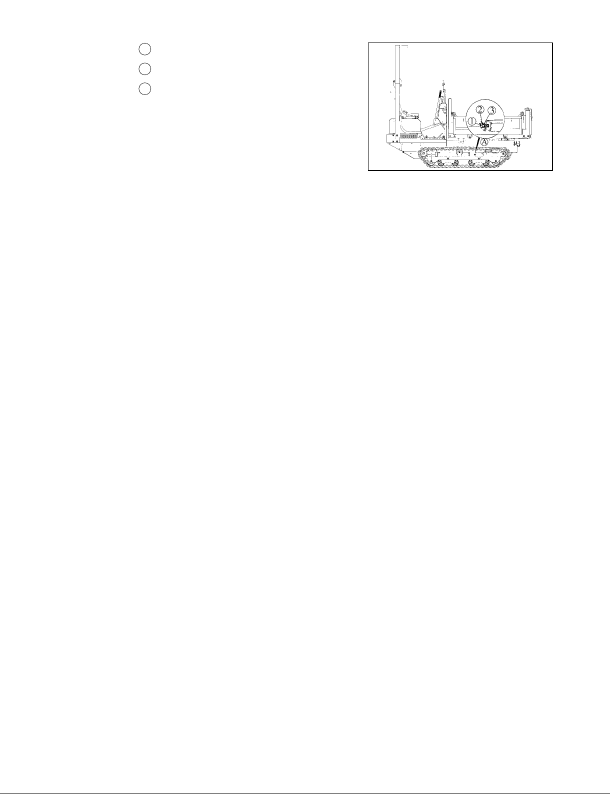
1 Adjusting bolt
Snap pin
2
Stopper
3
IMPORTANT
• Be sure to move the machine forward before
the adjustment. This is because, after backward
movement of the machine, the crawler is tensed on
the upper side, making correct adjustment impossible.
• The adjusting bolt will become difcult to turn when the sticking mud hardens.
•
After work, always grease the thread.
• Excessive tension results in trouble such as:
•
Increase of running resistance and reduction of driving power.
•
Excessive wear of crawler.
• Insufcient tension results in trouble such as:
•
Disengagement of crawler.
•
Defective engagement of sprocket.
•
Excessive wear of crawler.
• After completing the work, clean the crawler units, removing sticking soil completely.
37
Page 40
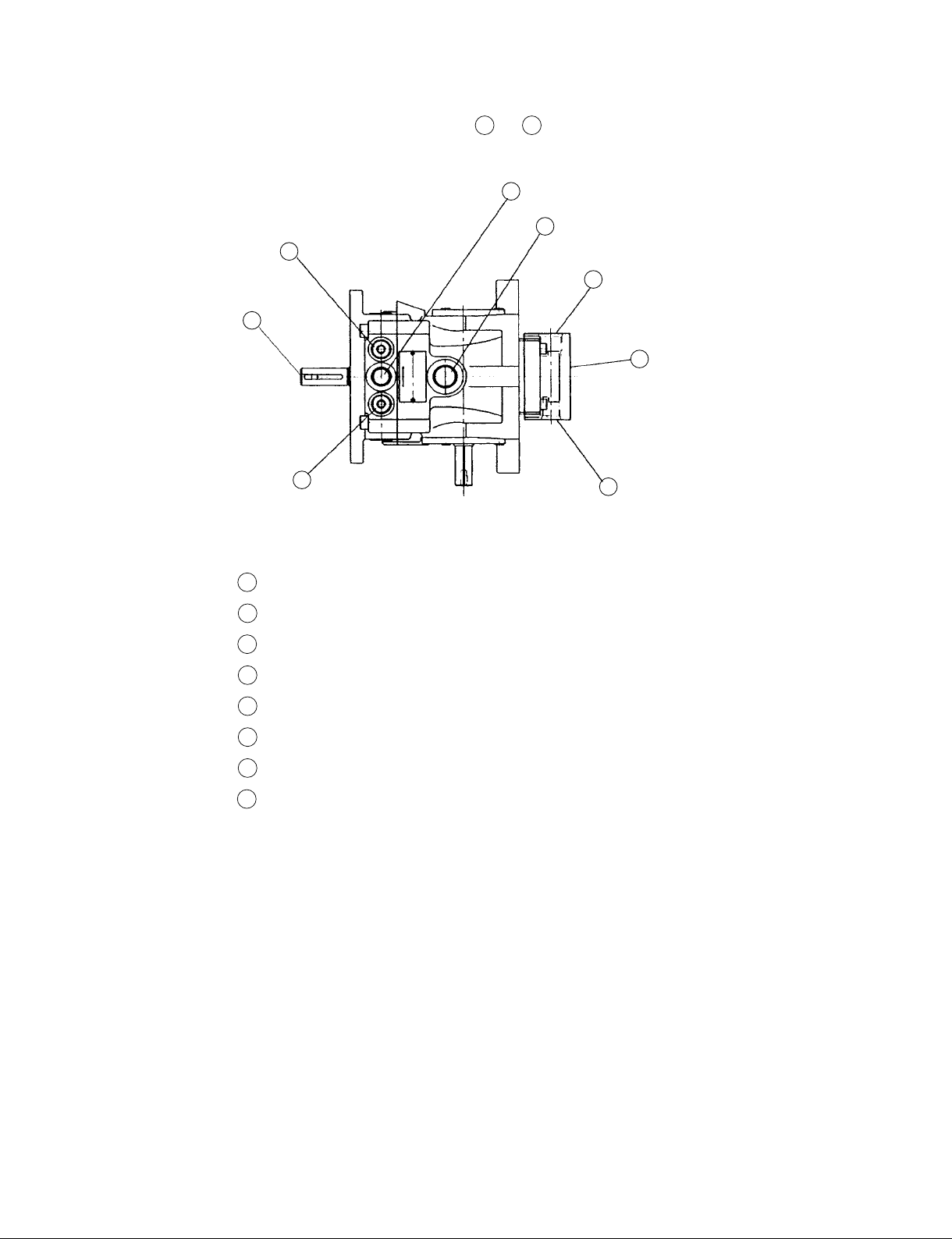
6. TESTING OF PRESSURE (HST)
Please check the pressure of HST by check port A or B .
4
1
3
5
7
6
2
Pressure check port (PF3/8) - FORWARD
1
Pressure check port (PF3/8) - BACKWARD
2
Input shaft
3
Suction port (PF3/8)
4
Drain port (PF3/8)
5
Charge pump
6
Suction port (PF1/2)
7
Discharge port (PF3/8)
8
8
38
Page 41
7. REPLACING OF WEAR OUT PARTS
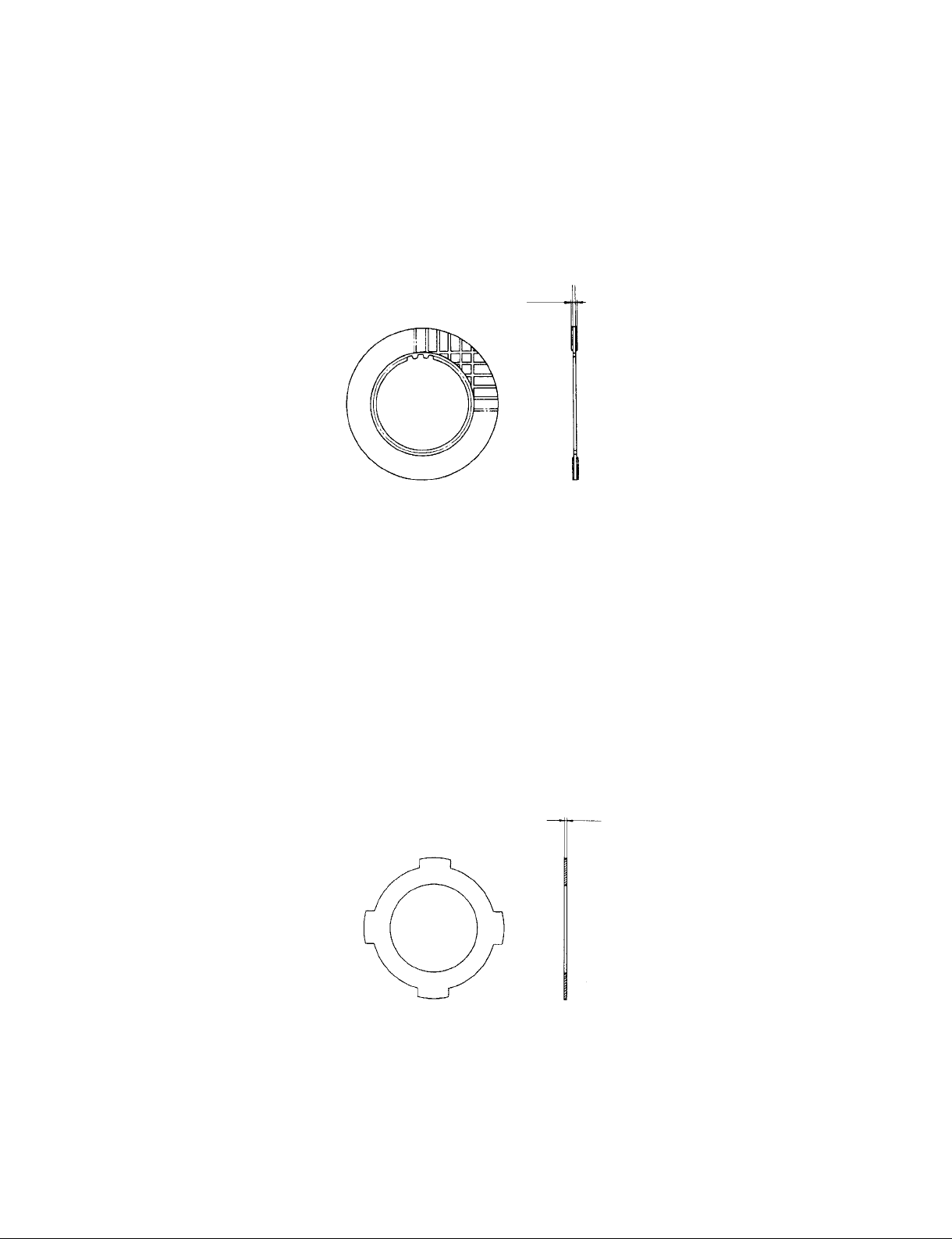
1) Friction plate
If the measurement is less than the allowable limit, replace the parts.
Friction plate thickness
Factory spec. 2.53 ~ 2.67mm
Allowable limit 2.35mm
2) Clutch plate
If the measurement is less than the allowable limit, replace the parts.
Clutch plate thickness
Factory spec. 0.95 ~ 1.05mm
Allowable limit 0.85 mm
39
Page 42
8. TROUBLESHOOTING AND COUNTERMEASURES
1. Engine is difcult to start (Self-starter does not operate).
Safety switch (brake pedal) is broken.
Check and replace.
2-1. The machine does not stop, even if remove the foot from drive pedal.
(Both side / Forward and Backward)
The bolt for lever (HST) is loosed.
Check and tighten up the bolt.
See “8. BOLTS FOR HST NEUTRAL LEVER” under “TIGHTENING TORQUE”.
2-2. The machine does not stop, even if remove the foot from drive pedal.
(one side only / Forward or Backward)
The neutral system of HST is not correctly adjusted.
Check and adjust the neutral system of HST.
See “4. NEUTRAL SYSTEM ADJUSTMENT” under “ADJUSTMENT OF COMPONENT
PARTS”.
3. The machine does not drive
HST pump is broken.
Check and replace.
4-1. The machine does not drive powerful.
The crawler tension is too high.
Check and adjust the crawler tension.
See “6. CRAWLER ADJUSTMENT” under “ADJUSTMENT OF COMPONENT PARTS”.
40
Page 43
4-2. The machine does not drive powerful.
The main clutch (V-belts) slips.
Check and adjust of V-belt tension (main clutch)
See “1. MAIN CLUTCH ADJUSTMENT” under “ADJUSTMENT OF COMPONENT
PARTS”.
4-3. The machine does not drive powerful.
Pressure of HST unit is not enough.
Check the pressure of HST unit.
See “TESTING OF PRESSURE (HST)”.
4-4. The machine does not drive powerful.
The parking brake is applied at all time.
Check and adjust of parking brake
See “2. BRAKE PEDAL ADJUSTMENT” under “ADJUSTMENT OF COMPONENT
PARTS”.
4-5. The machine does not drive powerful.
The brake pedal does not return correct position by lack of lubrication.
Check and apply a grease.
4-6. The machine does not drive powerful.
The friction between clutch plate and friction plate for transmission is big.
The friction will be decrease after 30 minutes or 1 hour operation.
41
Page 44
5. The operating force for steering lever is heavy.
The lubrication of rod, side clutch lever is not enough.
Check and apply a grease
6-1. The steering lever does not return smoothly.
The lubrication of rod, side clutch lever is not enough.
Check and apply a grease.
7. The speed change lever does not move smoothly.
The lubrication of rod is not enough.
Check and apply a grease
42
Page 45

9 MAINTENANCE INTERVALS
[EVERY 25 SERVICE HOURS]
• Check of steering lever
• Check of V-belt tension (main clutch)
[EVERY 50 SERVICE HOURS]
• Check of steering brake
• Check of parking brake
• Greasing
• Draining water of the fuel tank
• Check of rubber crawler tension
• Check of fuel pipes and clamp bands
[EVERY 100 SERVICE HOURS]
• Check of speed change lever
• Check of roller and idler
• Check of V-belt tension (hydraulic pump)
[after rst 25 service hours]
• Cleaning of air cleaner element
• Cleaning of fuel lter
• Check of battery electrolyte level
• Check of fan belt tension
• Change of engine oil
[after rst 50 service hours]
• Check of hydraulic hoses and clamp bands [HST]
[EVERY 200 SERVICE HOURS]
• Check of radiator hoses and clamp bands
• Check of hydraulic hoses and clamp bands (hydraulic pump)
• Replacement of oil lter cartridge
[after rst 50 service hours]
• Check of intake air line
[EVERY 300 SERVICE HOURS]
• Change of transmission oil
[after rst 50 service hours]
43
Page 46

[EVERY 400 SERVICE HOURS]
• Replacement of fuel lter element
• Cleaning of radiator
[EVERY 500 SERVICE HOURS]
• Replacement of fan belt
• Change of hydraulic pump oil
• Change of HST oil
[after rst 50 service hours]
• Replacement of oil lter cartridge [HST]
[after rst 50 service hours]
• Replacement of suction lter [HST]
[after rst 50 service hours]
[EVERY ONE OR TWO MONTHS]
• Recharging of battery
[EVERY ONE YEAR]
• Replacement of air cleaner element
[every year or every 6 times at cleaning]
• Check of the electrical circuit and looseness of the coupler
[EVERY 800 SERVICE HOURS]
• Check of valve clearance
[EVERY 1500 SERVICE HOURS]
• Check fuel injection nozzle injection pressure
[EVERY 2000 SERVICE HOURS]
• Check of alternator and starter motor
[EVERY TWO YEARS]
• Replacement of battery
• Replacement of radiator hoses and clamp bands
• Replacement of fuel pipes and clamps
• Change of radiator coolant (L.L.C.)
• Replacement of intake air line
• Replacement of hydraulic hoses and clamp bands
44
Page 47

Page 48
EDITOR:
KUBOTA CORPORATION
CONSTRUCTION MACHINERY DIVISION
CUSTOMER TECHNICAL SUPPORT DEPARTMENT
1-1-1 NAKAMIYA-OHIKE, HIRAKATA-CITY, OSAKA, 753-0004 JAPAN
PHONE : (81)72-890-2888
FAX : (81)72-890-2886
E-mail : [email protected]
KUBOTA Corporation
Printed in Japan 2010. 01, H, H, H, e Code No.RY921-20440
 Loading...