


SETUP INSTRUCTIONS 2016
Freeride E‑SM
Art. no. 3213505en


INTRODUCTION 1
INTRODUCTION
The work described in these setup instructions must be performed before the vehicle is delivered to the customer.
Read the setup instructions in their entirety before beginning work.
These setup instructions were written to correspond to the latest state of this series. We reserve the right to make changes in the interest
of technical advancement without at the same time updating this manual.
We shall not provide a description of general workshop methods. Likewise, safety rules that apply in a workshop are not specified here. It
is assumed that the work will be performed by a fully trained mechanic with the corresponding HV training.
All specifications are non-binding. KTM Sportmotorcycle GmbH specifically reserves the right to modify or delete technical specifications,
prices, colors, forms, materials, services, designs, equipment, etc., without prior notice and without specifying reasons, to adapt these to
local conditions, as well as to stop production of a particular model without prior notice. KTM accepts no liability for delivery options, deviations from illustrations and descriptions, misprints, and other errors. The models portrayed partly contain special equipment that does not
belong to the regular scope of supply.
© 2016 KTM Sportmotorcycle GmbH, Mattighofen Austria
All rights reserved
Reproduction, even in part, as well as copying of all kinds, is permitted only with the express written permission of the copyright owner.
ISO 9001(12 100 6061)
According to the international quality management standard ISO 9001, KTM uses quality assurance processes that lead to
the maximum possible quality of the products.
Issued by: TÜV Management Service
KTM Sportmotorcycle GmbH
5230 Mattighofen, Austria
This document is valid for the following models:
Freeride E-SM EU (F3001P2)
*3213505en*
3213505en
03/2016

1 MEANS OF REPRESENTATION 2
1.1 Symbols used
The meaning of specific symbols is described below.
Indicates an expected reaction (e.g. of a work step or a function).
Indicates an unexpected reaction (e.g. of a work step or a function).
Indicates work requiring expert knowledge and technical understanding. In the interest of your own safety, only
have these jobs performed by correspondingly trained KTM technical personnel.
All work identified by this symbol requires a level 1 qualification for high-voltage systems. Only this qualification
authorizes you to perform non-electro-technical work on a vehicle or on units with a high-voltage system.
All work identified by this symbol requires a level 2 qualification for high-voltage systems. Only this qualification
authorizes you to de-energize the electrical system and perform electro-technical work in a de-energized state.
All work identified by this symbol requires a level 3 qualification for high-voltage systems. Only this qualification
authorizes you to perform electro-technical work under voltage.
Indicates a page reference (more information is provided on the specified page).
Indicates information with more details or tips.
Indicates the result of a testing step.
Indicates a voltage measurement.
Indicates a current measurement.
Indicates a resistance measurement.
1.2 Formats used
The typographical formats used in this document are explained below.
Proprietary name Indicates a proprietary name.
®
Name
Brand™ Indicates a brand available on the open market.
Underlined terms Refer to technical details of the vehicle or indicate technical terms, which are explained
Indicates a protected name.
in the glossary.

2 SAFETY ADVICE 3
2.1 Work rules
The KTM PowerPack does not contain any parts that require maintenance. Do not open the KTM PowerPack under any circumstances.
Special tools are necessary for certain tasks. The tools are not a component of the vehicle, but can be ordered using the number in
parentheses. Example: transmission shaft holder (70029032000)
During assembly, non-reusable parts (e.g. self-locking screws and nuts, seals and seal rings, O-rings, pins, lock washers) must be
replaced by new parts.
In some instances, a thread locker (e.g. Loctite®) is required. The manufacturer instructions for use must be followed.
After disassembly, clean the parts that are to be reused and check them for damage and wear. Change damaged or worn parts.
After you complete the repair or service work, check the operating safety of the vehicle.
2.2 Safety advice
A number of safety instructions need to be followed to operate the vehicle safely. Therefore, read this manual carefully. The safety
instructions are highlighted in the text and are referred to at the relevant passages.
Info
The vehicle has various information and warning labels at prominent locations. Do not remove information/warning labels. If
they are missing, you or others may not recognize dangers and may therefore be injured.
2.3 Degrees of risk and symbols
Warning
Indicates a danger that is likely to lead to fatal or serious injury if the appropriate measures are not taken.
Caution
Indicates a danger that may lead to minor injuries if the appropriate measures are not taken.
Note
Indicates a danger that will lead to considerable machine and material damage if the appropriate measures are not taken.
Warning
Indicates a danger that will lead to environmental damage if the appropriate measures are not taken.
2.4 Operating and auxiliary substances
Use the operating and auxiliary substances (such as oils and lubricants) specified in the Owner's Manual.
2.5 Fire hazard
Warning
Fire hazard Damaged rechargeable lithium-ion batteries (KTM PowerPacks) present a fire hazard.
Massive mechanical damage may cause an internal cell short circuit and cause the battery to self-ignite.
– Contact the KTM customer service immediately if major damage to the rechargeable lithium-ion battery (KTM PowerPack)
has occurred.
There is no particular fire hazard for this vehicle when the rechargeable lithium-ion battery (KTM PowerPack) is intact.
However, should the vehicle catch fire, inform the fire brigade responsible that an electric vehicle with a rechargeable lithium-ion battery is on fire.

3 SETUP 4
0
0
0
0
3.1 Unpacking and setting up the vehicle
– Remove the box and the plastic packaging.
Info
An assistant prevents the motorcycle from falling over.
To avoid damaging the motorcycle during the setup, leave the protective
film on the vehicle until you have finished.
– Remove the separate enclosure and unpack it. Check that the scope of supply is
complete on the basis of the enclosed packing list.
C00858-10
– To be in compliance with the homologation of the vehicle, mount all of the parts in
the separate enclosure when assembling the vehicle.
Info
It is not necessary to mount all of the parts in the separate enclosure for the
vehicle to operate correctly. However, homologation will not apply if not all
parts from the separate enclosure are mounted.
– Remove the KTM PowerPack. ( p. 17)
– Have a lift stand available.
Lift stand (54829055000)
– Carefully loosen and remove the tension belt of the footrest bracket.
402050-01
C00761-10
Info
An assistant prevents the motorcycle from falling over.
– Together with an assistant, take the vehicle off the palette.
– Position the vehicle on a lift stand.
– Check the vehicle for transport damage.
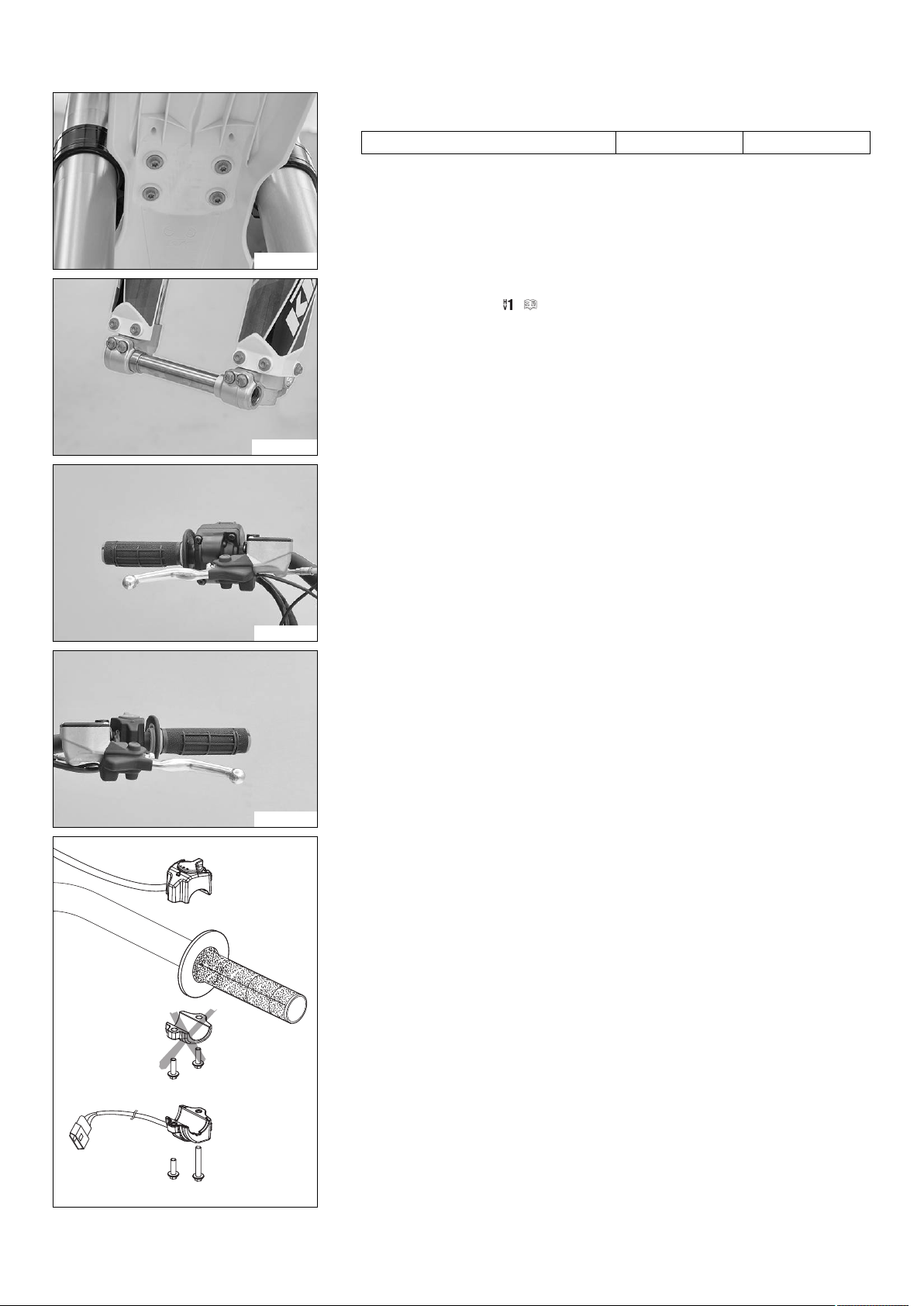
–
Remove screws. Take off the handlebar clamps.
–
Remove screws. Take off the handlebar supports.
– Place the handlebar supports in the required position. Mount and tighten
screws.
Guideline
Screw, handlebar support M10 40 Nm
(29.5 lbf ft)
Loctite®243™
Info
Position the left and right handlebar supports evenly.
– Position the handlebar.
Info
Make sure the cables and wiring are positioned correctly.
– Position the handlebar clamps. Mount and tighten the screws evenly.
Guideline
Screw, handlebar clamp M8 20 Nm
(14.8 lbf ft)
C00860-01
Info
The markings on the handlebar should be at the center of the handlebar
clamps.
Keep the gap widths equal when tightening.
3 SETUP 5
– Position the front fender and mount and tighten the screws.
Guideline
Remaining screws, chassis M6 10 Nm (7.4 lbf ft)
C00867-01
– Release the axle clamp screws and remove the wheel spindle.
– Install the front wheel. ( p. 11)
M00696-01
– Position the controls on the right half of the handlebar.
C00863-01
C00864-01
– Position the controls on the left half of the handlebar.
– Mount the turn signal switch and connect the plug-in connector on the wiring har-
ness.
402390-01
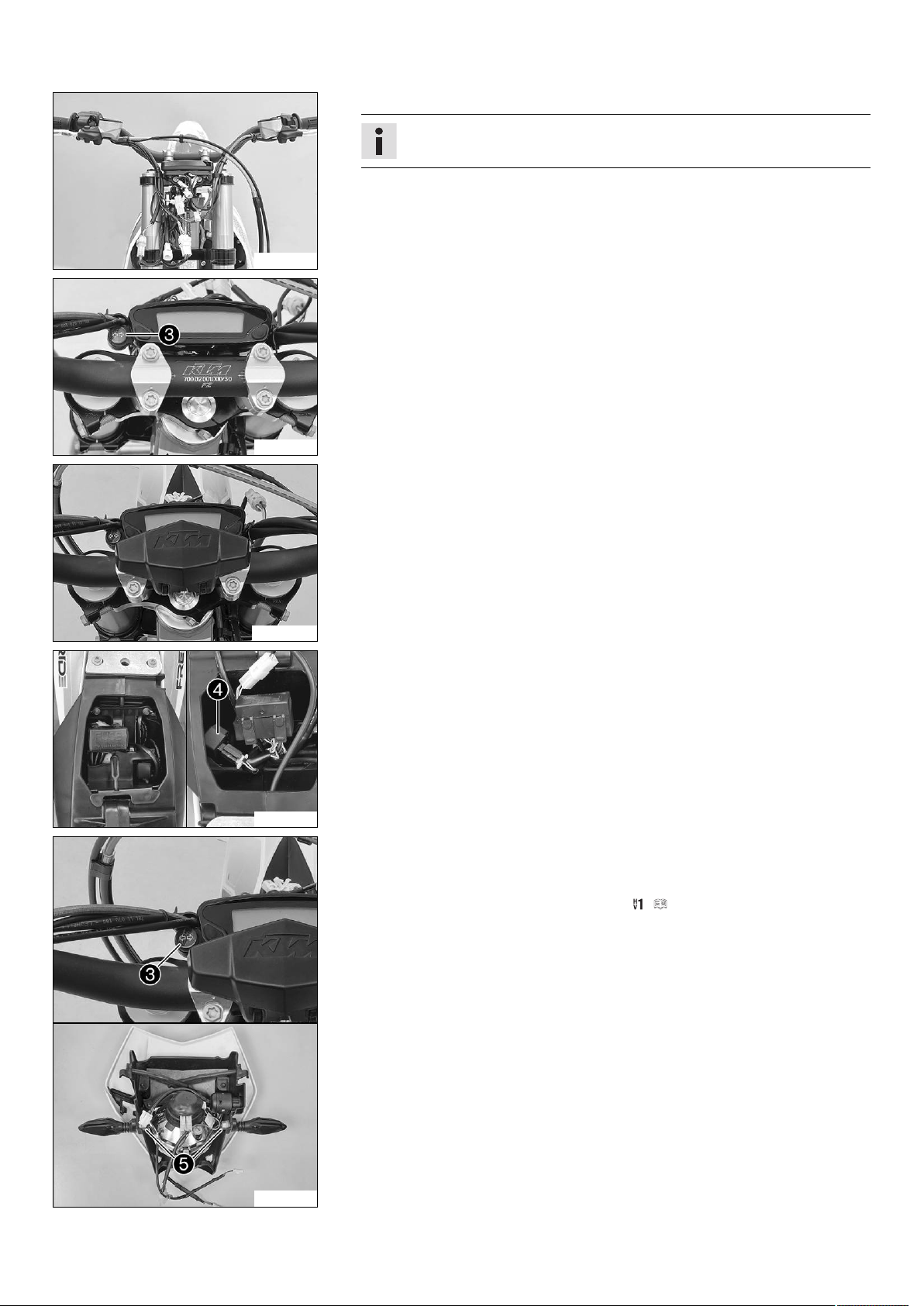
3 SETUP 6
– Connect all plug-in connectors to the connector retainer.
Info
Make sure the cables and wiring are positioned correctly.
C00865-01
–
Position turn signal indicator lamp.
C00866-10
– Mount the handlebar cushion.
M00697-01
C00868-10
– Take off the electrical compartment.
–
Connect turn signal relay.
– Route the wiring harness for the rear turn signal and license plate lamp and con-
nect the electrical consumers.
– Mount the electrical compartment.
– Insert the black and violet cables of the bulb included in the separate enclosure
into the socket and position it in the turn signal indicator lamp.
–
Position the turn signal on each side and mount and tighten nuts.
– Refit the headlight mask with the headlight. ( p. 20)
S01177-10

3 SETUP 7
– Mount the footrests with the springs and pins. Secure the pins using the washers
and cotter pins.
Pliers for footrest spring (58429083000)
M00695-01
– Mount the license plate holder with the license plate lamp, turn signals, and reflec-
tor.
– Connect the electrical components.
Info
The cable of the left turn signal is marked red.
The cable of the right turn signal is marked green.
S01178-01
– Recharge the 12 V battery. ( p. 16)
– Install the 12 V battery. ( p. 20)
– Unpack and mount the KTM PowerParts included in the delivery (optional).
C00740-01
M00700-01
Info
Read the accompanying KTM PowerParts fitting instructions.
– Apply the label included in the delivery (optional).
– Mount the mirror clamps on both sides.
– Mount and tighten the rear mirror on both sides.
M01438-01
C00869-10
Note
Material damage The ferrite core has a one-way lock.
If the locked ferrite core is reopened, the lock is destroyed.
– Before installing the ferrite core, ensure it is properly positioned.
–
Remove screw.
Info
The screw can be reached through a drill hole in the motor cover.

3 SETUP 8
–
Remove clamp.
– Remove the cable tie(s).
– Pull the wiring harness and brake line aside slightly.
C00870-10
–
Position ferrite corearound the lighting wiring harness and close it.
The ferrite core is fully closed and locked.
C00871-10
– Position the wiring harnesses, ferrite core, and brake line on the motor.
–
Position clamp.
C00872-10
C00869-10
C00874-01
–
Mount and tighten screw.
Guideline
Remaining screws for motor M6 10 Nm (7.4 lbf ft)
The clamp is fully closed but the cable is not pinched.
– Mount the cable tie(s).
– Position all controls in their exact positions on the handlebar. Tighten all screws.
– Carry out the unlocking procedure for the KTM PowerPack. ( p. 13)
– Prepare the vehicle according to the specifications in the KTM Dealer.net for han-
dover to the customer.

4 SERVICE WORK 9
4.1 Raising the motorcycle with the lift stand
Note
Danger of damage The parked vehicle may roll away or fall over.
– Always place the vehicle on a firm and even surface.
Preparatory work
– Deactivate the vehicle. ( p. 9)
– Fold the seat up. ( p. 12)
– Remove the KTM PowerPack. ( p. 17)
(Option: HV 2 technical personnel)
– Ascertain that the KTM PowerPack is at zero potential. ( p. 22)
– Ascertain that the discharge plug is de-energized. ( p. 22)
– Mount the covering cap. ( p. 10)
Main work
– Use the motor guard underneath the motor to raise the vehicle.
Lift stand (78929955100)
The wheels are no longer in contact with the ground.
– Secure the motorcycle against falling over.
401942-01
4.2 Removing the motorcycle from the lift stand
Note
Danger of damage The parked vehicle may roll away or fall over.
– Always place the vehicle on a firm and even surface.
Main work
– Remove the motorcycle from the lift stand.
– Remove the lift stand.
–
To park the motorcycle, press side standto the ground with your foot and lean
the motorcycle on it.
401943-10
Finishing work
– Install the KTM PowerPack. ( p. 18)
(Option: HV 2 technical personnel)
– Perform an equipotential bonding check (KTM PowerPack installed).
( p. 23)
– Lock the seat. ( p. 13)
4.3 Deactivating the vehicle
C00793-01
– Push the main switch into the position .

4 SERVICE WORK 10
– Turn the key in the ignition lock to the position while the vehicle is deactivated.
Remove the key.
K00037-01
4.4 Mounting the covering cap
Note
Material damage Components damaged or destroyed by water or dirt.
– Mount the covering cap if you have removed the KTM PowerPack.
Preparatory work
– Deactivate the vehicle. ( p. 9)
– Fold the seat up. ( p. 12)
– Remove the KTM PowerPack. ( p. 17)
(Option: HV 2 technical personnel)
– Ascertain that the KTM PowerPack is at zero potential. ( p. 22)
– Ascertain that the discharge plug is de-energized. ( p. 22)
Main work
– Check the battery discharge plug form ring. ( p. 11)
–
Mount the covering capwith one hand.
C00721-10
4.5 Removing the covering cap
Note
Material damage Components damaged or destroyed by water or dirt.
– Mount the covering cap if you have removed the KTM PowerPack.
Main work
–
Remove the covering capwith one hand.
C00721-10
Finishing work
– Install the KTM PowerPack. ( p. 18)
(Option: HV 2 technical personnel)
– Perform an equipotential bonding check (KTM PowerPack installed).
( p. 23)
– Lock the seat. ( p. 13)

4 SERVICE WORK 11
4.6 Checking the battery discharge plug form ring
Condition
The KTM PowerPack has been removed.
The covering cap has been removed.
–
Check the battery discharge plug form ringon the electric motor.
» If the battery discharge plug form ring is dirty:
– Ascertain that the discharge plug is de-energized. ( p. 22)
– Clean the form ring without using water or compressed air.
– Cover the contacts and spray silicone spray onto the form ring.
» If the battery discharge plug form ring is damaged:
– Change the battery discharge plug form ring. ( p. 23)
C00776-10
4.7 Installing the shock absorber
Main work
–
Push splash protectorto the side and position the shock absorber.
–
Mount and tighten screw.
Guideline
Screw, top shock absorber M12 80 Nm
(59 lbf ft)
Loctite®2701™
K00043-11
4.8 Installing the front wheel
–
Mount and tighten screw.
Guideline
Screw, bottom shock
absorber
M12 80 Nm
(59 lbf ft)
Info
The heim joint for the shock absorber at the swingarm is Teflon-coated. It
must not be greased with grease, nor with any other lubricants. Lubricants
dissolve the Teflon coating, thereby drastically reducing the service life.
–
Mount and tighten screw.
Guideline
Screw, upper subframe M10 45 Nm
(33.2 lbf ft)
Finishing work
– Remove the motorcycle from the lift stand. ( p. 9)
– Install the KTM PowerPack. ( p. 18)
(Option: HV 2 technical personnel)
– Perform an equipotential bonding check (KTM PowerPack installed).
( p. 23)
– Lock the seat. ( p. 13)
Loctite®2701™
Loctite®243™
Warning
Danger of accidents Reduced braking efficiency due to oil or grease on the brake discs.
– Always keep the brake discs free of oil and grease, and clean them with brake cleaner when necessary.

4 SERVICE WORK 12
Main work
– Check the wheel bearing for damage and wear.
» If the wheel bearing is damaged or worn:
– Change the front wheel bearing.
–
Clean and grease the shaft seal ringsand contact surfaceof the spacers.
Long-life grease ( p. 26)
– Insert the spacers.
C00734-11
– Position the front wheel and insert the wheel spindle.
The brake linings are correctly positioned.
–
Mount and tighten screw.
Guideline
Screw, front wheel spindle M20x1.5 35 Nm
(25.8 lbf ft)
– Operate the front brake lever several times until the brake linings are in contact
K00050-10
with the brake disc.
– Remove the motorcycle from the lift stand. ( p. 9)
– Operate the front brake and compress the fork a few times firmly.
The fork legs straighten.
–
Tighten screws.
Guideline
Screw, fork stub M8 15 Nm
(11.1 lbf ft)
4.9 Folding the seat up
Finishing work
– Install the KTM PowerPack. ( p. 18)
(Option: HV 2 technical personnel)
– Perform an equipotential bonding check (KTM PowerPack installed).
( p. 23)
– Lock the seat. ( p. 13)
–
Push the release leverin the direction of the arrow.
– Lift the seat and fold it up.
C00805-10

4 SERVICE WORK 13
DC 12 V
4.10 Locking the seat
– Fold down the seat and push it down.
The seat engages with an audible click.
– Finally, check that the seat is correctly locked.
C00804-01
4.11 Unlocking procedure for KTM PowerPack
Condition
The KTM PowerPack has been removed.
– Connect diagnosis cable to the KTM PowerPack.
AVL DiTEST adapter cable (70029069000)
– Connect the diagnostics tool and start it.
– Ensure external power supply for VCI using 12 V battery.
Blue LED on VCI lights up.
– Connect battery charger to the 12 V battery.
– Choose vehicle in the diagnostics tool and select "AutoScan".
– Execute "Battery management" > "Functions" > "Activate / deactivate transport mode".
– Install the KTM PowerPack. ( p. 18)
– Connect the diagnostics tool and start it.
– Clear the fault memory using the KTM diagnostics tool.
– Read out the fault memory using the KTM diagnostics tool.
» When fault memory is empty:
work is complete.
402173-51
4.12 Positioning the battery charger
Warning
Risk of injury There is a risk of electric shock in a moist environment.
The battery charger is not waterproof.
– Only use the battery charger in dry conditions.
– Ensure that no fluids flow or drip onto the battery charger.
Warning
Risk of injury If the battery charger is used incorrectly, its intrinsic safety cannot be guaranteed.
The battery charger is only suitable for use with a KTM PowerPack.
– Only use the battery charger with a KTM PowerPack.
– Only operate the battery charger using household sockets with an earth conductor.
– Do not use any additional adapters or extensions.
– Follow the applicable safety instructions of the power connection.

4 SERVICE WORK 14
Warning
Risk of injury There is a risk of electric shock if the battery charger or the cables have been manipulated or damaged.
The battery charger does not contain any parts which require maintenance.
– Do not modify the battery charger or the cables.
– Under no circumstances open the battery charger housing.
– Do not insert any objects into the battery charger housing from the outside.
– Do not use the battery charger if cables, plug or parts of the battery charger have been damaged or are soiled.
Info
The battery charger contains sensitive electronics and must be handled with appropriate care.
The battery charger may be damaged or destroyed if it is dropped, knocked or otherwise subject to mechanical overload.
When transporting the battery charger, ensure appropriate means of securing the cargo.
Damage caused due to improper handling or improper transport is excluded from the manufacturer warranty.
– Place the battery charger on a firm, level and horizontal surface.
– Ensure the battery charger is adequately ventilated.
Guideline
Free space at the front and rear side of
the battery charger
20 cm (7.9 in)
– Use the battery charger in the temperature range permitted.
Guideline
C00766-01
Ambient temperature −15… 50 °C (5… 122 °F)
– Ensure that the power plug for the battery charger always remains easily accessible.
4.13 Checking residual current protection switch
Warning
Risk of injury There is a risk of electric shock with a faulty residual current
protection switch.
– Before each use of the charger check the residual current protection
– Do not use the residual current protection switch if the test procedure
K00031-10
– Connect the mains plug to the mains connection.
–
Press thebutton .
The operating display lights up red.
–
Press thebutton .
The operating display goes out.
–
Press thebutton .
The residual current protection switch can be used.
– Disconnect the residual current protection switch from the mains connection.
switch.
was not successful.
4.14 Recharging the KTM PowerPack
Note
Material damage The power supply will be damaged in the event of an overload.
In charge mode Fast, a steady current of at least 13 A is required.
In charge mode Normal, a steady current of at least 10 A is required.
– Ensure that the power outlet can supply the steady current required and is protected by a suitable fuse.
Warning
Environmental hazard A lithium-ion battery (KTM PowerPack) contains components and elements that are harmful to the envi-
ronment.
– Never throw a KTM PowerPack into the household trash.
– Dispose of the KTM PowerPack properly and in compliance with the applicable regulations.

4 SERVICE WORK 15
Info
The procedure used for recharging is identical both when the battery is installed and when it is not installed. However, the
12 V battery is only recharged when the KTM PowerPack is being recharged in the vehicle.
Recharge the KTM PowerPack regularly while it is inside the vehicle to also charge the 12 V battery.
When the battery charger is connected to the KTM PowerPack, do not activate the vehicle.
If the vehicle is activated while recharging with the KTM PowerPack installed in the vehicle, the vehicle will switch to error
mode. The KTM PowerPack will continue to be recharged, however the 12 V battery will stop recharging.
Info
When the left LED in the charge level indicator on the battery charger flashes, then the KTM PowerPack is ready for use. However, its full capacity will not yet be available.
To guarantee the maximum capacity of the KTM PowerPack, discharge the KTM PowerPack completely every 20 charging
cycles and then recharge it completely. If this process is not carried out, then the vehicle may switch off due to a charging
level which is too low without reducing power beforehand.
The KTM PowerPack is completely discharged when the vehicle switches off with blink code 11.
Info
When the temperature of the KTM PowerPack exceeds the permitted value during charging, the battery charger will stop the
charging process. All LEDs and the LEDs for the current charge level light up alternately every second.
As soon the temperature of the KTM PowerPack returns to the permitted range, the charging process continues automatically.
Preparatory work
– Position the battery charger. ( p. 13)
– Check residual current protection switch. ( p. 14)
– Push the main switch into the position .
– Fold the seat up. ( p. 12)
Main work
–
Remove the charging socket protection cap.
C00815-10
C00768-10
Warning
Risk of injury The intrinsic safety of the KTM PowerPack can only be guar-
anteed if the original battery charger is used.
The KTM PowerPack may only be charged with the original battery charger.
– Only use the original battery charger to charge the KTM PowerPack.
–
Connect the battery charger to the KTM PowerPack. Observe the plug markings.
– Connect the power plug for the battery charger to the power supply socket.
–
Set the charging mode switchto the Fast position or Normal position.
Info
In charging mode Fast, the KTM PowerPack is completely charged after
approx. 80 minutes. The power consumption is higher than in charging
mode Normal.
In charging mode Normal, the KTM PowerPack is completely charged after
approx. 90 minutes.

4 SERVICE WORK 16
–
Switch on the battery charger using the switch.
The charging process starts automatically. The status indicator flashes during
the charging process.
C00769-10
– Monitor the charging level of the KTM PowerPack using the LEDs.
LED 1: 20%
LED 2: 40%
LED 3: 60%
LED 4: 80%
LED 5 flashes beginning with approx. 95 % until 100 % is reached.
Once the charging process is complete, all five LEDs light up and the status indica-
tor goes out.
C00770-10
–
Switch off the battery charger using the switch.
After several seconds, all LEDs on the battery charger go out.
– Disconnect the power plug for the battery charger from the power supply socket.
– Disconnect the charging cable from the KTM PowerPack.
Guideline
Pull on the structured part of the connector. Do not pull on the cable.
– Check the seal on the charging socket protection cap.
C00769-11
» If the seal is dirty:
– Clean the seal without using water or compressed air.
» If the seal is damaged or worn:
– Change the seal.
– Mount the charging socket protection cap.
Finishing work
– Lock the seat. ( p. 13)
4.15 Recharging the 12 V battery
Warning
Risk of injury Battery gases cause serious chemical burns.
– Keep batteries out of the reach of children.
– Wear suitable protective clothing and goggles.
– Avoid contact with battery gases.
– Keep sparks or open flames away from the battery.
– Only charge batteries in well-ventilated rooms.
– With skin contact rinse the affected area with plenty of water.
– Flush eyes with water for at least 15 minutes and consult a physician if battery gases have come into contact with the eyes.
Warning
Environmental hazard The battery contains elements that are harmful to the environment.
– Do not dispose of batteries with the household waste. Dispose of a defective battery in an environmentally friendly manner.
Give the battery to your authorized KTM dealer or dispose of it at a collection point for used batteries.

4 SERVICE WORK 17
Info
Even when there is no load on the battery, it discharges steadily.
The charging level and the method of charging are very important for the service life of the battery.
Rapid recharging with a high charging current shortens the service life of the battery.
If the charging current, charging voltage or charging time is exceeded, electrolyte escapes through the safety valves. This
reduces the battery capacity.
When the 12 V battery has been discharged (blink code 44 on the vehicle), recharge the 12 V battery with immediate effect.
If the battery is left in a discharged state for an extended period, it will become over-discharged and sulfated, destroying the
battery.
The battery is maintenance-free. The acid level does not have to be checked.
Info
The 12 V battery is recharged by the KTM PowerPack when operating the vehicle.
When the KTM PowerPack is recharged in the vehicle, then the 12 V battery is also recharged.
Preparatory work
– Fold the seat up. ( p. 12)
– Remove the 12 V battery. ( p. 19)
Main work
– Connect the battery charger to the battery. Switch on the battery charger.
Battery charger (58429074000)
Info
Never remove lid.
In addition, this battery charger can be used to test the open-circuit voltage.
This battery charger also makes overcharging the battery impossible.
C00740-10
– Switch off the battery charger after charging. Disconnect the battery from the bat-
tery charger.
Guideline
The charging current, charging voltage or charging time must not be exceeded.
Recharge the battery regularly when
the motorcycle is not being used:
Finishing work
– Install the 12 V battery. ( p. 20)
– Lock the seat. ( p. 13)
3 months
4.16 Removing the KTM PowerPack
Warning
Risk of injury There is a risk of electric shock when working on high-voltage components.
Work on high-voltage components require special training, qualifications and tools.
– Work which has not been described and explained may only be performed by correspondingly trained KTM specialists.
– Do not open the electric motor or the KTM PowerPack.
Warning
Environmental hazard A lithium-ion battery (KTM PowerPack) contains components and elements that are harmful to the envi-
ronment.
– Never throw a KTM PowerPack into the household trash.
– Dispose of the KTM PowerPack properly and in compliance with the applicable regulations.
Preparatory work
– Deactivate the vehicle. ( p. 9)
– Fold the seat up. ( p. 12)

4 SERVICE WORK 18
Main work
–
Loosen screws.
Note
Material damage Components damaged or destroyed by water or dirt.
– Mount the covering cap if you have removed the KTM PowerPack.
– Place the KTM PowerPack on a clean and dry surface.
–
Remove KTM PowerPack.
PowerPack lifting strap (70029022000)
Info
The KTM PowerPack is very heavy. A second person can help with removal.
402145-11
(Option: HV 2 technical personnel)
– Store the KTM PowerPack in a cabinet for hazardous goods.
Fire-resistant cabinet for hazardous goods (70029016000)
309887-10
Finishing work
– Mount the covering cap. ( p. 10)
4.17 Installing the KTM PowerPack
Caution
Risk of injury The KTM PowerPack is very heavy.
The KTM PowerPack must rest flush on the electric motor after installation.
– Only lift the KTM PowerPack using the carry handle.
– Make sure that nobody is pinched when the KTM PowerPack is removed or installed.
Note
Material damage Components damaged or destroyed by water or dirt.
– Before installing the KTM PowerPack, check that the battery discharge plug on the electric motor and the battery discharge socket
on the KTM PowerPack are clean.
– Check the battery discharge plug form ring.
– Clean the battery discharge plug and the battery discharge socket without using water or compressed air if the battery discharge
plug or the battery discharge socket is dirty.
– After cleaning, spray silicone spray onto the battery discharge plug form ring.
Preparatory work
(Option: HV 2 technical personnel)
– Perform an equipotential bonding check (KTM PowerPack installed).
( p. 23)
Main work
– Remove the covering cap. ( p. 10)
– Check the battery discharge plug form ring. ( p. 11)

4 SERVICE WORK 19
–
Position the KTM PowerPackin the vehicle.
PowerPack lifting strap (70029022000)
The KTM PowerPack is resting flush on the electric motor.
Info
The KTM PowerPack is very heavy. A second person can help with installation.
–
Tighten screws.
Guideline
KTM PowerPack attachment M6 10 Nm (7.4 lbf ft)
402145-12
Finishing work
(Option: HV 2 technical personnel)
– Perform an equipotential bonding check (KTM PowerPack installed).
( p. 23)
– Lock the seat. ( p. 13)
4.18 Removing the 12 V battery
Warning
Risk of injury Battery gases cause serious chemical burns.
– Keep batteries out of the reach of children.
– Wear suitable protective clothing and goggles.
– Avoid contact with battery gases.
– Keep sparks or open flames away from the battery.
– Only charge batteries in well-ventilated rooms.
– With skin contact rinse the affected area with plenty of water.
– Flush eyes with water for at least 15 minutes and consult a physician if battery gases have come into contact with the eyes.
Warning
Environmental hazard The battery contains elements that are harmful to the environment.
– Do not dispose of batteries with the household waste. Dispose of a defective battery in an environmentally friendly manner.
Give the battery to your authorized KTM dealer or dispose of it at a collection point for used batteries.
Preparatory work
– Fold the seat up. ( p. 12)
Main work
–
Detach rubber strap.
–
Disconnect negative cablefrom the 12 V battery.
–
Disconnect positive cablefrom the 12 V battery.
– Remove the 12 V battery.
C00920-10

4 SERVICE WORK 20
4.19 Installing the 12 V battery
Warning
Risk of injury Battery gases cause serious chemical burns.
– Keep batteries out of the reach of children.
– Wear suitable protective clothing and goggles.
– Avoid contact with battery gases.
– Keep sparks or open flames away from the battery.
– Only charge batteries in well-ventilated rooms.
– With skin contact rinse the affected area with plenty of water.
– Flush eyes with water for at least 15 minutes and consult a physician if battery gases have come into contact with the eyes.
Main work
–
Position the 12 V batteryin the battery compartment.
–
Connect the positive cableto the 12 V battery.
–
Connect the negative cableto the 12 V battery.
–
Reconnect rubber band.
C00920-11
4.20 Installing the front fender
C00702-10
Finishing work
– Lock the seat. ( p. 13)
Main work
– Position the front fender.
–
Mount and tighten screws.
Guideline
Remaining screws, chassis M6 10 Nm (7.4 lbf ft)
Finishing work
– Refit the headlight mask with the headlight. ( p. 20)
– Install the KTM PowerPack. ( p. 18)
(Option: HV 2 technical personnel)
– Perform an equipotential bonding check (KTM PowerPack installed).
( p. 23)
– Lock the seat. ( p. 13)
– Check the headlight setting. ( p. 21)
4.21 Refitting the headlight mask with the headlight
Main work
–
Connect plug-in connectors of turn signals, head light, and ignition
lock.
K00048-11

4 SERVICE WORK 21
00AA
0
0
BB
–
Position the headlight mask and fix it with rubber straps.
The holding lugs engage.
–
Position the brake line and wiring harness.
K00045-10
Finishing work
– Install the KTM PowerPack. ( p. 18)
(Option: HV 2 technical personnel)
– Perform an equipotential bonding check (KTM PowerPack installed).
( p. 23)
– Lock the seat. ( p. 13)
– Check the headlight setting. ( p. 21)
4.22 Checking the headlight setting
400726-10
– Position the vehicle upright on a horizontal surface in front of a light wall and make
a mark at the height of the center of the low beam headlight.
–
Make another mark at a distanceunder the first mark.
Guideline
Distance
–
Position the vehicle vertically a distanceaway from the wall.
Guideline
Distance
– The rider now sits down on the motorcycle with a full set of protective clothing.
– Turn the key in the ignition lock to the position .
– Push the main switch into the position .
– Switch on the low beam.
– Check the headlight setting.
The boundary between light and dark must be exactly on the lower mark for a
motorcycle with a rider.
» If the light-dark border does not meet specifications:
– Adjust the headlight range. ( p. 22)
5 cm (2 in)
5 m (16 ft)

4 SERVICE WORK 22
4.23 Adjusting the headlight range
Preparatory work
– Check the headlight setting. ( p. 21)
Main work
–
Adjust the beam distance of the headlight by turning screw.
Guideline
The boundary between light and dark must be exactly on the lower mark for a
motorcycle with a rider (instructions on how to apply the mark: Checking the
headlight setting).
Info
C00818-10
4.24 Ascertaining that the KTM PowerPack is at zero potential
Warning
Risk of injury The measuring points could be live.
– Use personal protective equipment and follow safety precautions.
Turn clockwise to increase the headlight range, turn counterclockwise to
reduce the headlight range.
A change in weight on the vehicle may require a correction of the headlight
range.
Condition
The KTM PowerPack has been removed.
Main work
– Prepare the special tool for measurement.
AVL Ditest HV Safety 2000 (70029068000)
– Start software HV Safety.
– Select "Zero-potential".
– Follow the instructions in the HV Safety Owner's Manual.
309699-10
Finishing work
– Mount the covering cap. ( p. 10)
4.25 Ascertaining that the discharge plug is de-energized
Warning
Risk of injury The measuring points could be live.
– Use personal protective equipment and follow safety precautions.
Condition
The KTM PowerPack has been removed.
Main work
– Prepare the special tool for measurement.
309699-10
AVL Ditest HV Safety 2000 (70029068000)
– Start software HV Safety.
– Select "Zero-potential".
– Follow the instructions in the HV Safety Owner's Manual.
Finishing work
– Mount the covering cap. ( p. 10)

4 SERVICE WORK 23
4.26 Performing an equipotential bonding check (KTM PowerPack installed)
Warning
Risk of injury The measuring points could be live.
– Use personal protective equipment and follow safety precautions.
Condition
The KTM PowerPack has been removed.
– Prepare the special tool for measurement.
AVL Ditest HV Safety 2000 (70029068000)
– Start software HV Safety.
– Select "Equipotential bonding check".
– Follow the instructions in the HV Safety Owner's Manual.
309699-10
4.27 Performing an equipotential bonding check (KTM PowerPack installed)
Warning
Risk of injury The measuring points could be live.
– Use personal protective equipment and follow safety precautions.
Condition
The KTM PowerPack has been removed.
– Prepare the special tool for measurement.
AVL Ditest HV Safety 2000 (70029068000)
– Start software HV Safety.
– Select "Equipotential bonding check".
– Follow the instructions in the HV Safety Owner's Manual.
309699-10
4.28 Changing the battery discharge plug form ring
Preparatory work
– Check the battery discharge plug form ring. ( p. 11)
– Ascertain that the discharge plug is de-energized. ( p. 22)
Main work
–
Remove the form ring.
311524-10

4 SERVICE WORK 24
– Spray silicone spray onto the new form ring.
– Mount the form ring.
311525-10
Finishing work
– Install the KTM PowerPack. ( p. 18)
(Option: HV 2 technical personnel)
– Perform an equipotential bonding check (KTM PowerPack installed).
( p. 23)
– Lock the seat. ( p. 13)

5 TECHNICAL DATA 25
5.1 chassis tightening torques
Spoke nipple M4.5 5 Nm (3.7 lbf ft) –
Screw, shock absorber adjusting ring M5 5 Nm (3.7 lbf ft) –
Screws, throttle grip M5 3 Nm (2.2 lbf ft) –
KTM PowerPack attachment M6 10 Nm (7.4 lbf ft) –
Remaining nuts, chassis M6 10 Nm (7.4 lbf ft) –
Remaining screws, chassis M6 10 Nm (7.4 lbf ft) –
Screw, front brake disc M6 14 Nm (10.3 lbf ft) Loctite®243™
Screw, radiator bracket M6 7 Nm (5.2 lbf ft) –
Screw, rear brake disc M6 14 Nm (10.3 lbf ft) Loctite®243™
KTM PowerPack attachment M8 15 Nm (11.1 lbf ft) Loctite®243™
Nut, rear sprocket screw M8 35 Nm (25.8 lbf ft) Loctite®2701™
Nut, rim lock M8 10 Nm (7.4 lbf ft) –
Remaining nuts, chassis M8 25 Nm (18.4 lbf ft) –
Remaining screws, chassis M8 25 Nm (18.4 lbf ft) –
Screw of rear brake caliper M8 25 Nm (18.4 lbf ft) Loctite®243™
Screw, bottom triple clamp M8 18 Nm (13.3 lbf ft) –
Screw, chain sliding piece M8 15 Nm (11.1 lbf ft) –
Screw, fork stub M8 15 Nm (11.1 lbf ft) –
Screw, front brake caliper M8 25 Nm (18.4 lbf ft) Loctite®243™
Screw, handlebar clamp M8 20 Nm (14.8 lbf ft) –
Screw, side stand attachment M8 25 Nm (18.4 lbf ft) Loctite®2701™
Screw, subframe M8 30 Nm (22.1 lbf ft) Loctite®243™
Screw, top steering stem M8 17 Nm (12.5 lbf ft) Loctite®243™
Screw, top triple clamp M8 22 Nm (16.2 lbf ft) –
Motor bracket screw M10 60 Nm (44.3 lbf ft) –
Remaining nuts, chassis M10 45 Nm (33.2 lbf ft) –
Remaining screws, chassis M10 45 Nm (33.2 lbf ft) –
Screw, cross bar M10 45 Nm (33.2 lbf ft) –
Screw, footrest bracket M10 45 Nm (33.2 lbf ft) Loctite®243™
Screw, handlebar support M10 40 Nm (29.5 lbf ft) Loctite®243™
Screw, motor guard M10 30 Nm (22.1 lbf ft) –
Screw, upper subframe M10 45 Nm (33.2 lbf ft) Loctite®243™
Screw, bottom shock absorber M12 80 Nm (59 lbf ft) Loctite®2701™
Screw, top shock absorber M12 80 Nm (59 lbf ft) Loctite®2701™
Nut, swingarm pivot M14x1.5 75 Nm (55.3 lbf ft) –
Nut, rear wheel spindle M20x1.5 80 Nm (59 lbf ft) –
Screw, front wheel spindle M20x1.5 35 Nm (25.8 lbf ft) –
Screw, top steering head M20x1.5 12 Nm (8.9 lbf ft) –

6 AUXILIARY SUBSTANCES 26
Long-life grease
Recommended supplier
®
Motorex
– Bike Grease 2000

*3213505en*
3213505en
03/2016
KTM Sportmotorcycle GmbH
5230 Mattighofen/Austria
http://www.ktm.com
Photo: Mitterbauer/KTM
 Loading...