

Page 1

SETUP INSTRUCTIONS 2012
Freeride 350
Art. no. 3211891en
Page 2

Page 3

INTRODUCTION 1
INTRODUCTION
The work described in these setup instructions must be performed before the vehicle is delivered to the customer.
Read the setup instructions in their entirety before beginning work.
Print out the current PDI form found on the KTM DEALER.NET.
These setup instructions were written to correspond to the latest state of this series. We reserve the right to make changes in the interest of technical advancement without at the same time updating this manual.
We shall not provide a description of general workshop methods. Likewise, safety rules that apply in a workshop are not specified here.
It is assumed that the work will be performed by a fully trained mechanic.
All specifications are non-binding. KTM Sportmotorcycle AG specifically reserves the right to modify or delete technical specifications, prices, colors, forms, materials, services, designs, equipment, etc., without prior notice and without specifying reasons, to adapt
these to local conditions, as well as to stop production of a particular model without prior notice. KTM accepts no liability for delivery
options, deviations from illustrations and descriptions, as well as misprints and other errors. The models portrayed partly contain special equipment that does not belong to the regular scope of supply.
© 2012 KTM-Sportmotorcycle AG, Mattighofen Austria
All rights reserved
Reproduction, even in part, as well as copying of all kinds, is permitted only with the express written permission of the copyright
owner.
ISO 9001(12 100 6061)
According to the international quality management standard ISO 9001, KTM uses quality assurance processes that lead
to the maximum possible quality of the products.
Issued by: TÜV Management Service
KTM-Sportmotorcycle AG
5230 Mattighofen, Austria
Page 4

1 MEANS OF REPRESENTATION 2
1.1 Symbols used
The meaning of specific symbols is described below.
Indicates an expected reaction (e.g. of a work step or a function).
Indicates an unexpected reaction (e.g. of a work step or a function).
Indicates a page reference (more information is provided on the specified page).
Indicates information with more details or tips.
Indicates the result of a testing step.
Denotes a voltage measurement.
Denotes a current measurement.
Denotes a resistance measurement.
1.2 Formats used
The typographical formats used in this document are explained below.
Proprietary name Identifies a proprietary name.
®
Name
Brand™ Identifies a trademark.
Identifies a protected name.
Page 5

2 SAFETY ADVICE 3
2.1 Work rules
Special tools are necessary for certain tasks. The tools are not contained in the vehicle but can be ordered under the number in parentheses. E.g.: bearing puller (15112017000)
During assembly, non-reusable parts (e.g. self-locking screws and nuts, seals and seal rings, O-rings, pins, lock washers) must be
replaced by new parts.
In some instances, a thread locker (e.g. Loctite®) is required. The manufacturer instructions for use must be followed.
After disassembly, clean the parts that are to be reused and check them for damage and wear. Change damaged or worn parts.
After you complete the repair or service work, check the operating safety of the vehicle.
2.2 Safety advice
A number of safety instructions need to be followed to operate the vehicle safely. Therefore, read this manual carefully. The safety
instructions are highlighted in the text and are referred to at the relevant passages.
Info
The vehicle has various information and warning labels at prominent locations. Do not remove information/warning labels. If
they are missing, you or others may not recognize dangers and may therefore be injured.
2.3 Degrees of risk and symbols
Danger
Identifies a danger that will immediately and invariably lead to fatal or serious permanent injury if the appropriate measures
are not taken.
Warning
Identifies a danger that is likely to lead to fatal or serious injury if the appropriate measures are not taken.
Note
Identifies a danger that will lead to considerable machine and material damage if the appropriate measures are not taken.
Warning
Identifies a danger that will lead to environmental damage if the appropriate measures are not taken.
2.4 Operating and auxiliary substances
Warning
Environmental hazard Improper handling of fuel is a danger to the environment.
– Do not allow fuel to get into the ground water, the ground, or the sewage system.
Use the operating and auxiliary substances (such as fuel and lubricants) as specified in the manual.
Page 6
3 SETUP 4
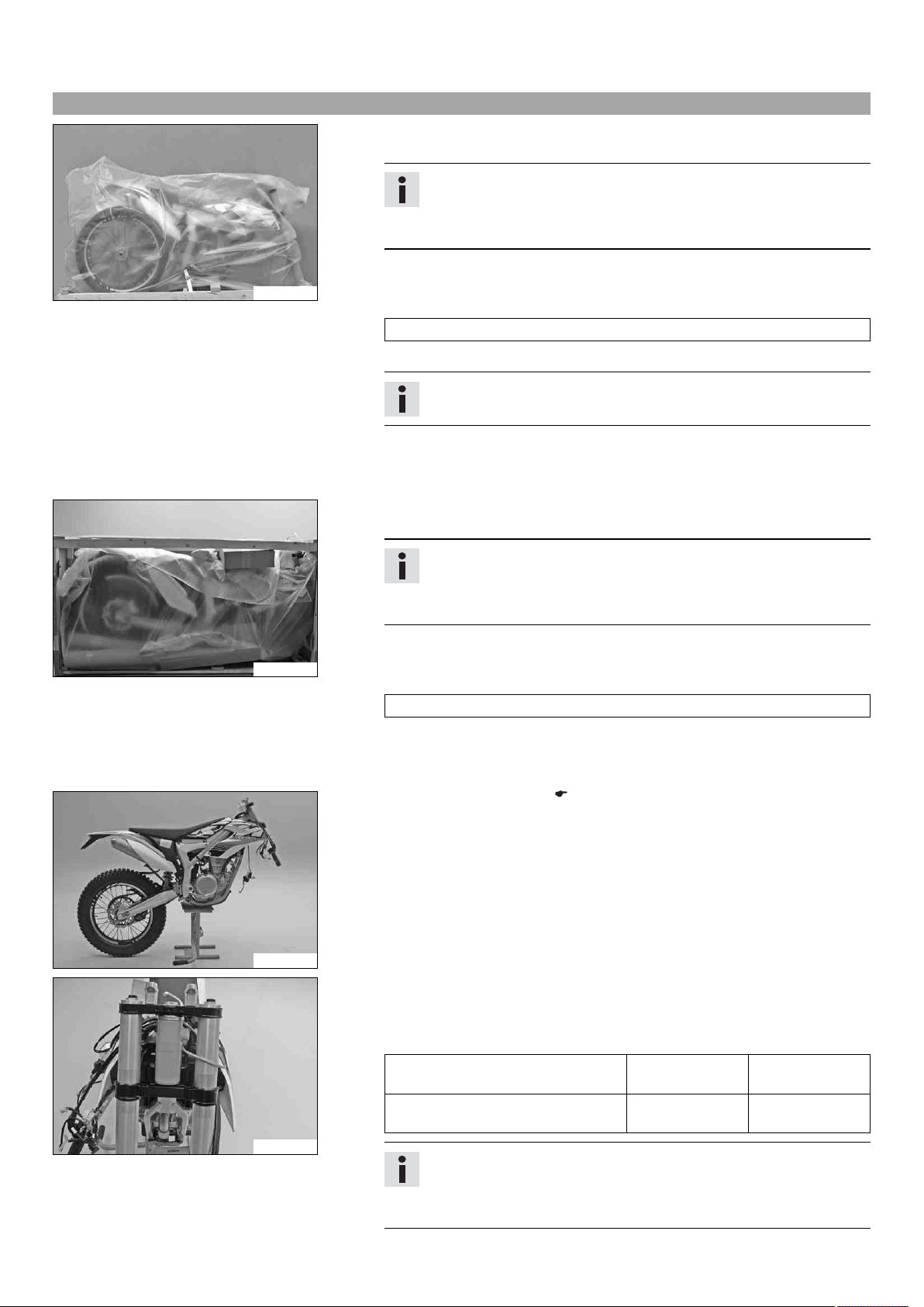
3.1 Unpacking and setting up the vehicle
Packaging 2
– Remove the box and the plastic packaging.
Info
An assistant prevents the motorcycle from falling over.
To avoid damaging the motorcycle during setup, leave the protective
film on the vehicle until you have finished.
– Remove the separate enclosure and unpack it. Check that the scope of delivery
B01160-01
is complete on the basis of the enclosed packing list.
– Have a lift stand available.
Lift stand (54829055000)
– Carefully loosen and remove the footrest bracket.
Info
An assistant prevents the motorcycle from falling over.
– Together with an assistant, take the vehicle off the pallet.
– Position the vehicle on a lift stand.
– Check the vehicle for transport damage.
Package 12
– Remove the box and the plastic packaging.
B01161-01
B01162-01
B01163-01
Info
An assistant prevents the motorcycle from falling over.
To avoid damaging the motorcycle during setup, leave the protective
film on the vehicle until you have finished.
– Remove the separate enclosure and unpack it. Check that the scope of delivery
is complete on the basis of the enclosed packing list.
– Have a lift stand available.
Lift stand (54829055000)
– Together with an assistant, take the vehicle off the pallet.
– Position the vehicle on a lift stand.
– Check the vehicle for transport damage.
– Install the shock absorber. ( p. 8)
– Route the clutch line with the clutch master cylinder toward the front between
the upper and lower triple clamps.
– Position the fork legs and tighten the screws of the triple clamp.
Guideline
Screw, top triple clamp M8 22 Nm
(16.2 lbf ft)
Screw, bottom triple clamp M8 18 Nm
(13.3 lbf ft)
Info
The lowest milled groove in the fork leg must be flush with the top edge
of the upper triple clamp.
Position the bleeder screws toward the front.
Page 7

3 SETUP 5
0
0
– Remove screws 1. Remove the handlebar clamp.
– Remove screws 2. Remove the handlebar holders.
– Place the handlebar holders in the required position. Mount and tighten screws 2.
Guideline
B01036-10
B01164-01
Screw, handlebar support M10 40 Nm
(29.5 lbf ft)
Info
Position the left and right handlebar holders evenly.
– Position the handlebar.
Info
Make sure cables and wiring are positioned correctly.
– Position the handlebar clamps. Mount and tighten the screws.
Guideline
Screw, handlebar clamp M8 20 Nm
Info
The markings on the handlebar should be at the center of the handlebar
clamps.
Keep the gap widths equal when tightening.
Loctite®243™
(14.8 lbf ft)
B01165-10
B01176-01
– Install the front wheel. ( p. 8)
– Mount the handlebar cushion.
– Attach connector holder 3 and the speedometer to the upper triple clamp.
Guideline
Remaining screws, chassis M6 10 Nm (7.4 lbf ft)
– Remove the fuel tank. ( p. 9)
– Position the turn signal wiring harness on the main wiring harness and secure with
cable binders.
Info
The figure shows how to route the wiring harness.
– Connect all connectors to connector holder 3.
– Install the fuel tank. ( p. 10)
– Insert bulb 4, included in the separate enclosure, into the socket with the black
and violet cable colors and position in the turn signal indicator lamp 5.
B01177-10
Page 8
3 SETUP 6
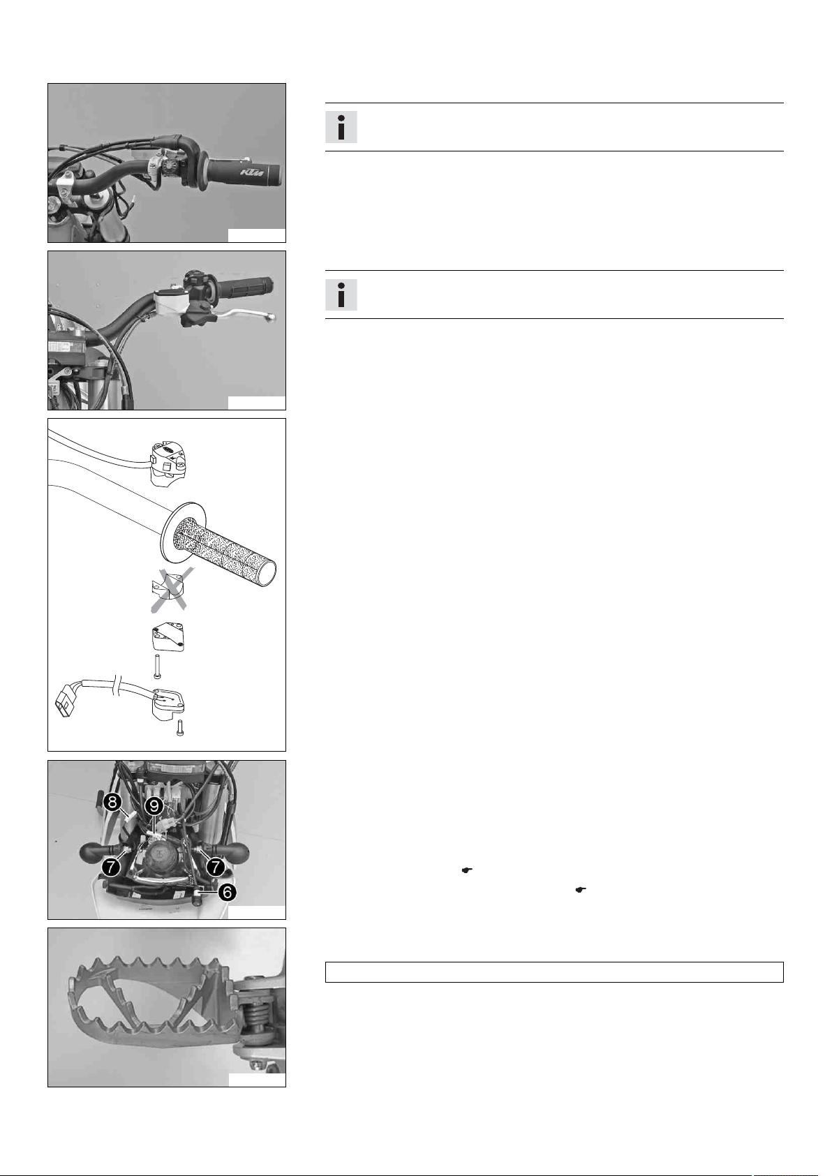
– Position the controls of the right half of the handlebar.
Info
The routing of the cables can be seen in the figure.
B01167-01
– Position the controls of the left half of the handlebar.
Info
The figure shows how to route the clutch line and wiring harness.
B01168-01
– Mount the turn signal switch.
401382-01
B01169-10
800042-10
– Insert the indicator lamp with the blue and brown cable colors into socket 6.
– Position the turn signals on both sides and mount and tighten nuts 7.
– Connect plug-in connection 8 of the right turn signal with the black and brown
cable colors.
– Connect plug-in connection 9 of the left turn signal with the violet and brown
cable colors.
– Install the front fender. ( p. 13)
– Refit the headlight mask with the headlight. ( p. 13)
– Mount the footrests with the springs and bolts. Secure the bolts using the washers
and pins.
Pliers for footrest spring (58429083000)
Page 9

3 SETUP 7
– Mount the license plate holder with the license plate lamp, turn signals, and reflec-
tor.
– Connect the electrical components.
– Connect the connector of the left turn signal with connector that is marked red.
– Connect the connector of the right turn signal with connector that is marked green.
B01170-01
Warning
Risk of injury Battery acid and battery gases cause serious chemical burns.
– Keep batteries out of the reach of children.
– Wear suitable protective clothing and goggles.
– Avoid contact with battery acid and battery gases.
– Keep the battery away from sparks or open flames. Charge only in well-
ventilated areas.
B01173-01
– In the event of skin contact, rinse with large amounts of water. If battery
acid gets in the eyes, rinse with water for at least 15 minutes and contact a physician.
B01172-01
– Fill the battery.
Info
Read the notes in the battery package.
– Recharge the battery. ( p. 12)
– Install the battery. ( p. 13)
– Unpack and mount the KTM PowerParts included in the delivery (optional).
Info
Read the accompanying KTM PowerParts installation instructions.
– Apply the label included in the delivery (optional).
– Mount the mirror clamps on both sides.
– Mount and tighten the rear mirrors on both sides.
– Position all controls in their exact positions on the handlebar. Tighten all screws.
– Refuel. ( p. 15)
– Print out the current PDI form found on KTM DEALER.NET and perform the delivery
inspection.
B01171-01
Page 10
4 SERVICE WORK ON THE CHASSIS 8
4.1 Installing the shock absorber
Main work
– Push splash protector 1 to the side and position the shock absorber. Mount and
tighten screw 2.
Guideline
B01053-11
Screw, top shock absorber M12 80 Nm
– Mount and tighten screw 3.
Guideline
Screw, bottom shock
absorber
M12 80 Nm
Info
The heim joint for the shock absorber at the swing arm is Teflon coated. It
must not be greased with grease or with other lubricants. Lubricants dissolve the Teflon coating, thereby drastically reducing the service life.
– Mount and tighten screw 4.
Guideline
Screw, upper subframe M10 45 Nm
(59 lbf ft)
(59 lbf ft)
(33.2 lbf ft)
Loctite®243™
Loctite®243™
Loctite®243™
Subsequent work
– Lock the seat. ( p. 9)
– Remove the motorcycle from the lift stand.
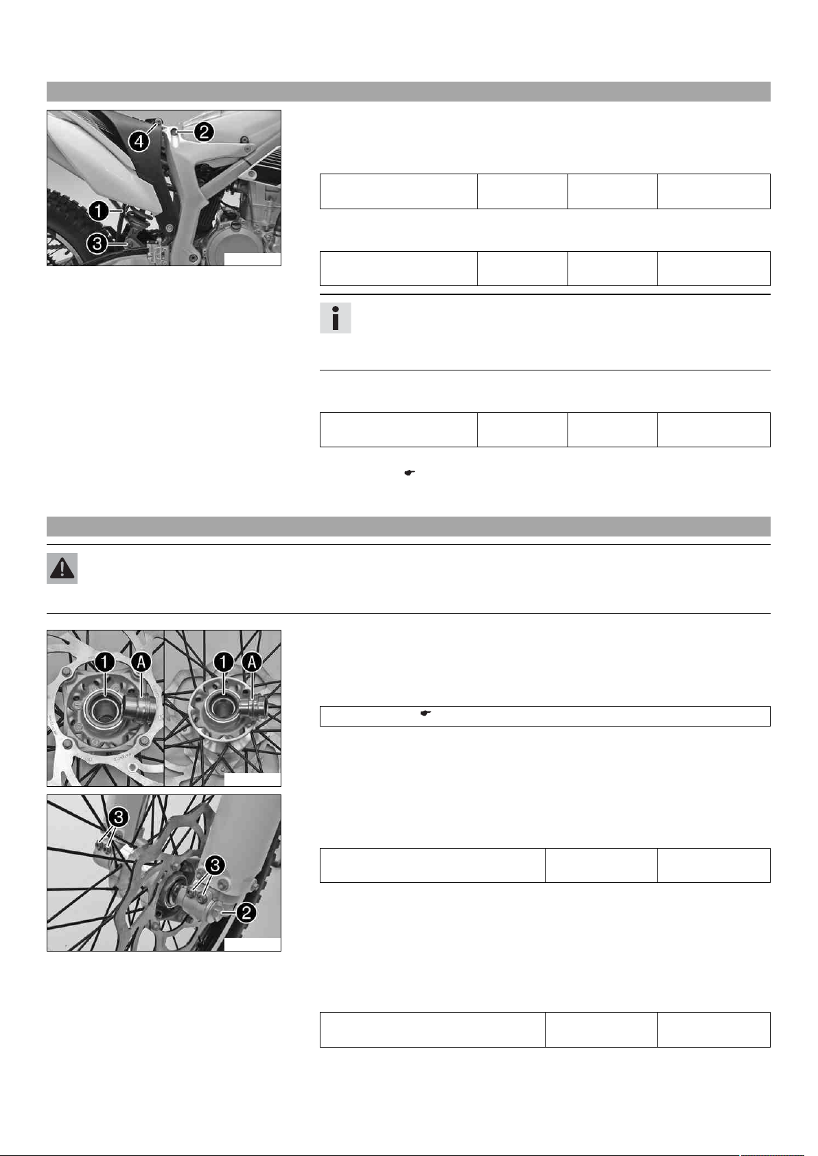
4.2 Installing the front wheel
Warning
Danger of accidents Reduced braking efficiency due to oil or grease on the brake discs.
– Always keep the brake discs free of oil and grease, and clean them with brake cleaner when necessary.
– Check the wheel bearing for damage and wear.
» If the wheel bearing is damaged or worn:
– Change the wheel bearing.
– Clean and grease the shaft seal rings 1 and contact surface A of the spacers.
Long-life grease ( p. 19)
– Insert the spacers.
B01046-11
– Lift the front wheel into the fork, position it, and insert the wheel spindle.
– Mount and tighten screw 2.
Guideline
Screw, front wheel spindle M20x1.5 35 Nm
(25.8 lbf ft)
B01044-11
– Activate the hand brake lever multiple times until the brake linings are in contact
with the brake disc.
–
Remove the motorcycle from the lift stand.
– Pull the front wheel brake and push down hard on the fork several times to align
the fork legs.
– Tighten screw 3.
Guideline
Screw, fork stub M8 15 Nm
(11.1 lbf ft)
Page 11

4 SERVICE WORK ON THE CHASSIS 9
4.3 Folding the seat up
– Press release lever 1.
– Lift the seat and fold it up.
B01021-10
4.4 Locking the seat
– Fold down the seat and push it down.
The seat engages with an audible click.
– Finally, check that the seat is correctly locked.
B01022-10
4.5 Removing the fuel tank
Danger
Fire hazard Fuel is highly flammable.
– Never refuel the vehicle near open flames or burning cigarettes, and always switch off the engine first. Be careful that no
fuel is spilt, especially on hot vehicle components. Clean up spilt fuel immediately.
– Fuel in the fuel tank expands when warm and can escape if the tank is overfilled. See the notes on refueling.
Warning
Danger of poisoning Fuel is poisonous and a health hazard.
– Avoid contact between fuel and skin, eyes and clothing. Do not inhale fuel vapors. If fuel gets into your eyes, rinse immedi-
ately with water and contact a doctor. Wash affected skin areas immediately with soap and water. If fuel is swallowed, contact a doctor immediately. Change clothing that has come into contact with fuel. Store fuel in a suitable canister according
to regulations and keep it out of the reach of children.
B01074-10
Preliminary work
– Fold the seat up. ( p. 9)
Main work
– Thoroughly clean the plug-in connection of the fuel line using compressed air.
Info
Under no circumstances should dirt enter the fuel line. Dirt in the fuel line
clogs the injection valve.
– Disconnect the plug-in connection of the fuel line.
Page 12

4 SERVICE WORK ON THE CHASSIS 10
– Mount wash cap set 1.
Wash cap set (81212016000)
– Remove the tube from the fuel tank breather.
– Remove screws 2 on both sides.
– Remove screw 3.
B01075-10
– Disconnect connector 4.
– Pull off engine breather hose 5.
B01076-10
– Release hose clamp 6.
– Detach the intake flange from the throttle valve body.
B01077-10
– Pull up the fuel tank slightly and disconnect connector 7 of the fuel pump.
– Remove the fuel tank from above.
B01078-10
4.6 Installing the fuel tank
Danger
Fire hazard Fuel is highly flammable.
– Never refuel the vehicle near open flames or burning cigarettes, and always switch off the engine first. Be careful that no
fuel is spilt, especially on hot vehicle components. Clean up spilt fuel immediately.
– Fuel in the fuel tank expands when warm and can escape if the tank is overfilled. See the notes on refueling.
Warning
Danger of poisoning Fuel is poisonous and a health hazard.
– Avoid contact of the fuel with skin, eyes and clothing. Do not inhale fuel vapors. If fuel gets into your eyes, rinse imme-
diately with water and contact a doctor. Wash affected skin areas immediately with soap and water. If fuel is swallowed,
contact a doctor immediately. Change clothing that has come into contact with fuel.
Page 13

4 SERVICE WORK ON THE CHASSIS 11
Main work
– Check the throttle cable routing.
– Make sure that no cables are trapped or damaged.
– Attach connector 1 of the fuel pump.
B01078-11
– Position the fuel tank.
– Position the intake flange on the throttle valve body.
– Tighten hose clamp 2.
B01077-11
– Plug in connector 3.
– Position engine breather hose 4.
B01076-11
B01075-11
B01079-10
– Mount and tighten screws 5 on both sides.
Guideline
Screw, fuel tank M8 15 Nm
(11.1 lbf ft)
– Mount and tighten screw 6.
Guideline
Remaining screws, chassis M6 10 Nm (7.4 lbf ft)
– Mount the fuel tank breather.
– Thoroughly clean the plug-in connection of the fuel line using compressed air.
Info
Under no circumstances should dirt enter into the fuel line. Dirt in the fuel
line clogs the injection valve.
– Remove the wash cap set. Lubricate the O-ring and connect plug-in connection 7
of the fuel line.
Info
Route the cable and fuel line at a safe distance from the exhaust system.
Subsequent work
– Lock the seat. ( p. 9)
Page 14

4 SERVICE WORK ON THE CHASSIS 12
4.7 Recharging the battery
Warning
Risk of injury Battery acid and battery gases cause serious chemical burns.
– Keep batteries out of the reach of children.
– Wear suitable protective clothing and goggles.
– Avoid contact with battery acid and battery gases.
– Keep the battery away from sparks or open flames. Charge only in well-ventilated areas.
– In the event of skin contact, rinse with large amounts of water. If battery acid gets in the eyes, rinse with water for at least
15 minutes and contact a physician.
Warning
Environmental hazard The battery contains elements that are harmful to the environment.
– Do not discard batteries with the household trash. Dispose of a defective battery in an environmentally compatible manner.
Give the battery to your KTM dealer or to a recycling center that accepts used batteries.
Warning
Environmental hazard Hazardous substances cause environmental damage.
– Oil, grease, filters, fuel, cleaners, brake fluid, etc., should be disposed of as stipulated in applicable regulations.
Info
Even when there is no load on the battery, it discharges steadily.
The charge state and the type of charge are very important for the service life of the battery.
Rapid recharging with a high charging current shortens the battery's service life.
If the charging current, charging voltage, and charging time are exceeded, electrolyte escapes through the safety valves. This
reduces the battery capacity.
If the battery is depleted from starting the vehicle repeatedly, the battery must be charged immediately.
If the battery is left in a discharged state for an extended period, it will become over-discharged and sulfate, destroying the
battery.
The battery is maintenance-free, i.e., the acid level does not have to be checked.
Preliminary work
– Remove the battery.
Main work
– Connect the battery charger to the battery. Switch on the battery charger.
Battery charger (58429074000)
You can also use the battery charger to test the rest potential and starting ability of
the battery, and to test the alternator. With this device, you cannot overcharge the
battery.
Info
400240-10
Never remove lid 1.
Charge the battery with a maximum of 10% of the capacity specified on the
battery housing 2.
– Switch off the charger after charging. Disconnect the battery.
Guideline
The charging current, charging voltage, and charging time must not be exceeded.
Charge the battery regularly when the
motorcycle is not in use
Subsequent work
– Install the battery. ( p. 13)
3 months
Page 15

4 SERVICE WORK ON THE CHASSIS 13
4.8 Installing the battery
– Connect the positive cable.
Guideline
Screw, battery terminal M5 2.5 Nm
(1.84 lbf ft)
– Attach negative cable.
Guideline
Screw, battery terminal M5 2.5 Nm
(1.84 lbf ft)
Battery (YTX4L-BS)
Info
Contact disk A must be mounted between screw 1 and cable socket 2
with the claws facing down.
– Slide positive terminal cover 3 over the positive terminal.
B01104-10
– Position the battery in the battery compartment.
– Attach fixing flap 4.
– Mount and tighten screw 5.
B01102-11
4.9 Installing the front fender
– Ensure that the spacers are mounted in the fender.
– Position the front fender. Mount and tighten screws 1.
Guideline
Remaining screws, chassis M6 10 Nm (7.4 lbf ft)
Info
Make sure the holding lugs engage in the headlight mask.
B01030-10
4.10 Refitting the headlight mask with the headlight
Main work
– Insert bulb socket 1 into the high beam indicator lamp.
– Plug in connector.
B01169-12
Page 16

4 SERVICE WORK ON THE CHASSIS 14
00AA
0
0
BB
– Position the headlight mask and fix it with the rubber band 3.
Info
Make sure that the holding lugs engage in the fender.
– Position the brake line and wiring harness 4.
B01041-11
Subsequent work
– Check the headlight setting. ( p. 14)
4.11 Checking the headlight setting
400726-10
4.12 Adjusting the headlight range
– Position the vehicle upright on a horizontal surface in front of a light wall and make
a mark at the height of the center of the low beam headlight.
– Make another mark at a distance B under the first mark.
Guideline
Distance B 5 cm (2 in)
– Position the vehicle vertically a distance A away from the wall.
Guideline
Distance A 5 m (16 ft)
– The rider now sits down on the motorcycle.
– Switch on the low beam.
– Check the headlight setting.
The boundary between light and dark must be exactly on the lower mark for a
motorcycle with driver.
» If the boundary between light and dark does not meet specifications:
– Adjust the headlight range. ( p. 14)
Preliminary work
– Check the headlight setting. ( p. 14)
Main work
– Adjust the beam distance of the headlight by turning screw 1.
Guideline
For a motorcycle with rider, the light/dark boundary must be exactly on the lower
mark (the mark is created in: Checking the headlight setting).
B01043-10
Info
Turn clockwise to increase the headlight range, turn counterclockwise to
reduce the headlight range.
A change in weight on the vehicle may require a correction of the headlight
range.
Page 17

4 SERVICE WORK ON THE CHASSIS 15
4.13 Opening the filler cap
Danger
Fire hazard Fuel is highly flammable.
– Never refuel the vehicle near open flames or burning cigarettes, and always switch off the engine first. Be careful that no
fuel is spilt, especially on hot vehicle components. Clean up spilt fuel immediately.
– Fuel in the fuel tank expands when warm and can escape if the tank is overfilled. See the notes on refueling.
Warning
Danger of poisoning Fuel is poisonous and a health hazard.
– Avoid contact between fuel and skin, eyes and clothing. Do not inhale fuel vapors. If fuel gets into your eyes, rinse immedi-
ately with water and contact a doctor. Wash affected skin areas immediately with soap and water. If fuel is swallowed, contact a doctor immediately. Change clothing that has come into contact with fuel. Store fuel in a suitable canister according
to regulations and keep it out of the reach of children.
Warning
Environmental hazard Improper handling of fuel is a danger to the environment.
– Do not allow fuel to get into the ground water, the ground, or the sewage system.
Preliminary work
– Fold the seat up. ( p. 9)
Main work
– Press release button 1, turn the filler cap counterclockwise, and lift it free.
B01019-10
4.14 Closing the filler cap
Main work
– Replace the filler cap and turn clockwise until the release button 1 locks in place.
Info
Run the fuel tank breather hose 2 without kinks.
B01020-10
Subsequent work
– Lock the seat. ( p. 9)
4.15 Refueling
Danger
Fire hazard Fuel is highly flammable.
– Never refuel the vehicle near open flames or burning cigarettes, and always switch off the engine first. Be careful that no
fuel is spilt, especially on hot vehicle components. Clean up spilt fuel immediately.
– Fuel in the fuel tank expands when warm and can escape if the tank is overfilled. See the notes on refueling.
Warning
Danger of poisoning Fuel is poisonous and a health hazard.
– Avoid contact of the fuel with skin, eyes and clothing. Do not inhale fuel vapors. If fuel gets into your eyes, rinse imme-
diately with water and contact a doctor. Wash affected skin areas immediately with soap and water. If fuel is swallowed,
contact a doctor immediately. Change clothing that has come into contact with fuel.
Note
Material damage Premature clogging of the fuel filter.
Page 18

4 SERVICE WORK ON THE CHASSIS 16
– In some countries and regions, the available fuel quality and cleanliness may not be sufficient. This will result in problems with
the fuel system.
– Only refuel with clean fuel that meets the specified standards.
Warning
Environmental hazard Improper handling of fuel is a danger to the environment.
– Do not allow fuel to get into the ground water, the ground, or the sewage system.
Preliminary work
– Switch off the engine.
– Fold the seat up. ( p. 9)
– Open the filler cap. ( p. 15)
Main work
– Fill the fuel tank with fuel up to measurement A.
Guideline
Measurement of A 30 mm (1.18 in)
401474-10
Total fuel tank
capacity, approx.
Subsequent work
– Close the filler cap. ( p. 15)
– Lock the seat. ( p. 9)
4.8 l
(1.27 US gal)
Super unleaded (ROZ 95/RON 95/PON
91) ( p. 18)
Page 19

5 TECHNICAL DATA - CHASSIS TIGHTENING TORQUES 17
Spoke nipple M4.5 5… 6 Nm (3.7… 4.4 lbf ft) –
Screw, battery terminal M5 2.5 Nm (1.84 lbf ft) –
Screw, shock absorber adjusting ring M5 5 Nm (3.7 lbf ft) –
Remaining nuts, chassis M6 10 Nm (7.4 lbf ft) –
Remaining screws, chassis M6 10 Nm (7.4 lbf ft) –
Screw, ball joint of push rod on foot
brake cylinder
Screw, front brake disc M6 14 Nm (10.3 lbf ft)
Screw, rear brake disc M6 14 Nm (10.3 lbf ft)
Screws, throttle grip M6 3 Nm (2.2 lbf ft) –
Fuel connection on fuel pump M8 10 Nm (7.4 lbf ft) –
Nut, foot brake lever stop M8 20 Nm (14.8 lbf ft) –
Nut, rear sprocket screw M8 35 Nm (25.8 lbf ft)
Nut, rim lock M8 10 Nm (7.4 lbf ft) –
Remaining nuts, chassis M8 25 Nm (18.4 lbf ft) –
Remaining screws, chassis M8 25 Nm (18.4 lbf ft) –
Screw of rear brake caliper M8 25 Nm (18.4 lbf ft)
Screw, bottom triple clamp M8 18 Nm (13.3 lbf ft) –
Screw, chain sliding piece M8 15 Nm (11.1 lbf ft) –
Screw, fork stub M8 15 Nm (11.1 lbf ft) –
Screw, front brake caliper M8 25 Nm (18.4 lbf ft)
Screw, fuel tank M8 15 Nm (11.1 lbf ft) –
Screw, handlebar clamp M8 20 Nm (14.8 lbf ft) –
Screw, side stand attachment M8 25 Nm (18.4 lbf ft)
Screw, subframe M8 30 Nm (22.1 lbf ft)
Screw, top steering stem M8 17 Nm (12.5 lbf ft)
Screw, top triple clamp M8 22 Nm (16.2 lbf ft) –
Nut, fuel tank attachment M10 10 Nm (7.4 lbf ft) –
Remaining nuts, chassis M10 45 Nm (33.2 lbf ft) –
Remaining screws, chassis M10 45 Nm (33.2 lbf ft) –
Screw, cross bar M10 45 Nm (33.2 lbf ft) –
Screw, engine bracket screw M10 60 Nm (44.3 lbf ft) –
Screw, foot brake lever M10 30 Nm (22.1 lbf ft)
Screw, footrest bracket M10 45 Nm (33.2 lbf ft)
Screw, handlebar support M10 40 Nm (29.5 lbf ft)
Screw, upper subframe M10 45 Nm (33.2 lbf ft)
Nut, fuel pump fixation M12 15 Nm (11.1 lbf ft) –
Screw, bottom shock absorber M12 80 Nm (59 lbf ft)
Screw, top shock absorber M12 80 Nm (59 lbf ft)
Nut, swingarm pivot M14x1.5 75 Nm (55.3 lbf ft) –
Nut, rear wheel spindle M20x1.5 80 Nm (59 lbf ft) –
Screw, front wheel spindle M20x1.5 35 Nm (25.8 lbf ft) –
Screw, top steering head M20x1.5 12 Nm (8.9 lbf ft) –
M6 10 Nm (7.4 lbf ft)
Loctite®243™
Loctite®243™
Loctite®243™
Loctite®243™
Loctite®243™
Loctite®243™
Loctite®243™
Loctite®243™
Loctite®243™
Loctite®243™
Loctite®243™
Loctite®243™
Loctite®243™
Loctite®243™
Loctite®243™
Page 20

6 SUBSTANCES 18
Super unleaded (ROZ 95/RON 95/PON 91)
According to
– DIN EN 228 (ROZ 95/RON 95/PON 91)
Guideline
– Only use unleaded super fuel that matches or is equivalent to the specified fuel grade.
– Fuel with an ethanol content of up to 10 % (E10 fuel) is safe to use.
Info
Do not use fuel containing methanol (e. g. M15, M85, M100) or more than 10 % ethanol (e. g. E15, E25, E85, E100).
Page 21

7 AUXILIARY SUBSTANCES 19
Long-life grease
Guideline
– KTM recommends Motorex®products.
Supplier
®
Motorex
– Bike Grease 2000
Page 22

*3211891en*
3211891en
04/2012
KTM-Sportmotorcycle AG
5230 Mattighofen/Austria
http://www.ktm.com
Photo: Mitterbauer/KTM
 Loading...