


SETUP INSTRUCTIONS 2018
Freeride 250 F
Art. no. 3213743en


INTRODUCTION
INTRODUCTION
Perform the work described in these setup instructions before the vehicle is delivered to the customer.
Read the setup instructions in their entirety before beginning work.
These setup instructions were written to correspond to the latest state of this series. We reserve the right to make
changes in the interest of technical advancement without at the same time updating this manual.
We shall not provide a description of general workshop methods. Likewise, safety rules that apply in a workshop
are not specified here. It is assumed that the work will be performed by a fully trained mechanic.
All specifications are non-binding. KTM Sportmotorcycle GmbH specifically reserves the right to modify or delete
technical specifications, prices, colors, forms, materials, services, designs, equipment, etc., without prior notice
and without specifying reasons, to adapt these to local conditions, as well as to stop production of a particular
model without prior notice. KTM accepts no liability for delivery options, deviations from illustrations and descriptions, misprints, and other errors. The models portrayed partly contain special equipment that does not belong to
the regular scope of supply.
© 2017 KTM Sportmotorcycle GmbH, Mattighofen Austria
All rights reserved
Reproduction, even in part, as well as copying of all kinds, is permitted only with the express written permission
of the copyright owner.
ISO 9001(12 100 6061)
According to the international quality management standard ISO 9001, KTM uses quality assurance processes that lead to the maximum possible quality of the products.
Issued by: TÜV Management Service
KTM Sportmotorcycle GmbH
Stallhofnerstraße 3
5230 Mattighofen, Austria
This document is valid for the following models:
Freeride 250 F EU (F8103R4)
*3213743en*
3213743en
08/2017

1 MEANS OF REPRESENTATION
1.1 Symbols used
The meaning of specific symbols is described below.
Indicates an expected reaction (e.g. of a work step or a function).
Indicates an unexpected reaction (e.g. of a work step or a function).
Indicates a page reference (more information is provided on the specified page).
Indicates information with more details or tips.
Indicates the result of a testing step.
Indicates a voltage measurement.
Indicates a current measurement.
Indicates a resistance measurement.
Indicates the end of an activity including potential rework.
1.2 Formats used
The typographical formats used in this document are explained below.
Proprietary name Indicates a proprietary name.
®
Name
Brand™ Indicates a brand available on the open market.
Underlined terms Refer to technical details of the vehicle or indicate technical terms, which
Indicates a protected name.
are explained in the glossary.
2

2.1 Unpacking and setting up the vehicle
Condition
Packaging V2
– Unpack and set up the V2 vehicle. ( p. 4)
– Remove V2 headlight mask. ( p. 4)
Condition
Packaging V12
– Unpack and set up the V12 vehicle. ( p. 5)
– Install V12 fork legs. ( p. 5)
– Install V12 shock absorber. ( p. 6)
– Install C12 combination instrument. ( p. 6)
– Stick on the reflector. ( p. 7)
– Install handlebars. ( p. 7)
– Install the handlebar cushion. ( p. 8)
– Install left side controls. ( p. 8)
– Install right side controls. ( p. 10)
– Install left and right rear mirrors. ( p. 11)
– Install left and right hand guards. ( p. 11)
– Install front fender. ( p. 12)
– Install the front wheel. ( p. 12)
– Install the front and rear turn signals. ( p. 13)
– Install the license plate lamp. ( p. 14)
– Install the reflector. ( p. 14)
– Route the front turn signal cable. ( p. 14)
– Route the rear turn signal cable. ( p. 15)
– Install the license plate holder extension. ( p. 18)
– Remove the motorcycle from the lift stand. ( p. 19)
– Install the engine guard. ( p. 19)
– Install the footrests. ( p. 19)
– Recharge the battery. ( p. 20)
– Install the headlight mask with the headlight. ( p. 22)
– Check the headlight setting. ( p. 23)
– Adjust the combination instrument. ( p. 23)
– Adjust kilometers or miles. ( p. 24)
– Adjust the clock. ( p. 25)
– Refuel. ( p. 25)
– Unpack and mount the KTM PowerParts included in the delivery (optional).
SETUP 2
Info
Read the accompanying KTM PowerParts fitting instructions.
– Remove remaining protective film.
– Attach the sticker included in the delivery (optional).
– Prepare the vehicle according to the specifications in the KTM Dealer.net for handover to the customer.
Info
Transport mode must be deactivated to be able to start the motorcycle.
3

3 SERVICE WORK ON THE CHASSIS
3.1 Unpacking and setting up the V2 vehicle
E00851-10
– Remove the box and the plastic packaging.
Info
An assistant prevents the motorcycle from falling over.
To avoid damaging the motorcycle during the setup,
leave the protective film on the vehicle until you have
finished.
– Remove and unpack the separate enclosure and attachments.
Check that the scope of supply is complete using the enclosed
packing list.
– Have a lift stand available.
Lift stand (78929955100)
– Carefully loosen and remove the tension belt of the footrest
mount.
Info
An assistant prevents the motorcycle from falling over.
402050-01
3.2 Removing V2 headlight mask
F01233-10
– Together with an assistant, take the vehicle off the pallet.
– Position the vehicle on a lift stand.
– Check the vehicle for transport damage.
– Remove the spare key and KEYCODECARD and keep in a safe
place for the handover.
–
Loosen rubber band1and tilt headlight mask forwards.
–
Disconnect the plug-in connector2of the headlight and the
plug-in connector3of the ignition lock.
– Lay down the headlight mask carefully to the side and protect
from damage.
E00971-10
4

3.3 Unpacking and setting up the V12 vehicle
– Remove the box and the plastic packaging.
– Remove and unpack the separate enclosure and attachments.
E00850-10
Check that the scope of supply is complete using the enclosed
packing list.
– Remove the spare key and KEYCODECARD and keep in a safe
place for the handover.
– Have a lift stand available.
Lift stand (78929955100)
– Remove the two cable ties on the triple clamp.
– Together with an assistant, take the vehicle off the pallet.
– Position the vehicle on a lift stand.
– Check the vehicle and attachments for transport damage.
SERVICE WORK ON THE CHASSIS 3
Info
An assistant prevents the motorcycle from falling over.
To avoid damaging the motorcycle during the setup,
leave the protective film on the vehicle until you have
finished.
402051-01
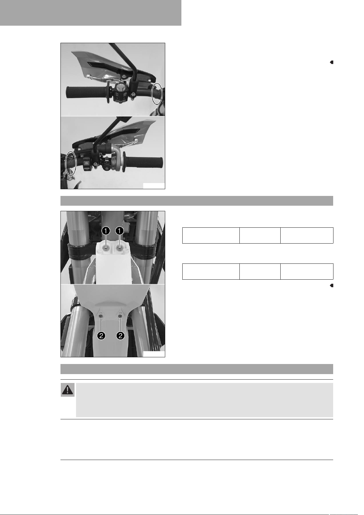
3.4 Installing V12 fork legs
402556-10
E00974-10
– Position the fork legs.
Bleeder screws1are positioned toward the front.
Info
Grooves are milled into the side of the upper end of the
fork legs. The second milled groove (from the top) must
be flush with the upper edge of the upper triple clamp.
–
Tighten screws2.
Guideline
Screw, top triple
clamp
–
Tighten screws3.
Guideline
Screw, bottom triple
clamp
M8 22 Nm (16.2 lbf ft)
M8 18 Nm (13.3 lbf ft)
5

3 SERVICE WORK ON THE CHASSIS
F01200-10
3.5 Installing V12 shock absorber
F01209-11
–
Position the brake caliper. Mount and tighten screws4with
the spacers.
Guideline
Screw, front
brake caliper
–
Connect plug-in connector5and mount the cable tie(s).
– Position the brake line, wiring harness, and clamp. Mount and
tighten screws6.
–
Push splash protector1to the side and position the shock
absorber. Mount and tighten screw2.
Guideline
Screw, top
shock absorber
–
Mount and tighten screw3.
Guideline
Screw, bottom
shock absorber
M8 25 Nm (18.4 lbf ft)
Loctite®243™
M12 80 Nm (59 lbf ft)
Loctite®2701™
M12 80 Nm (59 lbf ft)
Loctite®2701™
–
Mount and tighten screw4.
Guideline
Screw, upper
subframe
–
Attach brake line5.
3.6 Installing V12 combination instrument
– Position the connector retainer and speedometer on the upper
triple clamp.
–
Mount and tighten screws1.
Guideline
Remaining screws,
chassis
– Route the clutch line with the clutch master cylinder toward
H02569-10
the front between the upper and lower triple clamps.
Info
The heim joint for the shock absorber at the swingarm
is Teflon-coated. It must not be greased with grease,
nor with any other lubricants. Lubricants dissolve the
Teflon coating, thereby drastically reducing the service
life.
M10 45 Nm (33.2 lbf ft)
Loctite®243™
M6 10 Nm (7.4 lbf ft)
6

3.7 Sticking on the reflector
F01234-01
3.8 Installing handlebars
SERVICE WORK ON THE CHASSIS 3
– Make sure that the reflectors are glued on to the left and right
fork leg.
» If there are no reflectors stuck on:
– Stick on the reflector.
Info
The reflectors must not be covered by trim
parts.
–
Remove screws1. Take off the handlebar supports.
– Place the handlebar supports in the required position. Mount
and tighten screws1.
Guideline
Screw, handlebar support
M10 40 Nm (29.5 lbf ft)
Loctite®243™
F01235-10
E00957-10
Info
Position the left and right handlebar supports evenly.
Warning
Danger of accidents A repaired handlebar poses a
safety risk.
If the handlebar is bent or straightened, the mate-
rial becomes fatigued. The handlebar may break as a
result.
– Change the handlebar if the handlebar is damaged
or bent.
– Position the handlebar.
Info
Make sure the cables and wiring are positioned correctly.
– Position the handlebar clamps. Mount and tighten the screws
evenly.
Guideline
Screw, handlebar
clamp
M8 20 Nm (14.8 lbf ft)
7

3 SERVICE WORK ON THE CHASSIS
3.9 Installing the handlebar cushion
E00958-10
Info
The handlebar clamps and screws are in the accessory
pack.
The markings on the handlebar should be at the center
of the handlebar clamps.
Keep the gap widths equal when tightening.
– Secure the handlebar cushion with two cable ties.
3.10 Installing left side controls
402148-01
– Mount turn signal switch and route cable to the front.
– Position the controls on the left half of the handlebar.
E00959-01
8

E01055-10
F01220-01
SERVICE WORK ON THE CHASSIS 3
– Route the cables without tension and secure with cable ties
and cable holders.
Condition
Customer request: non-approved installation for road use.
Warning
Voiding of the government approval for road use and
the insurance coverage If the combination switch
is installed, the vehicle's approval for road use is
invalidated.
– Only operate the vehicle in closed-off areas
remote from public road traffic if the combination switch is installed.
F01222-10
– Mount left side combination switch.
Combination switch, left side (79039974044)
Info
The left side combination switch is optionally available as an accessory.
With the combination switch mounted the second
mapping and traction control can be used.
The figure shows a possible installation position of
the left side combination switch.
Observe the accompanying KTM PowerParts fitting
instructions.
The launch control is not available for this model.
–
Remove the protection cap and join plug-in connector
of the left combination switch.
– Route the cable without tension and secure with cable
tie(s).
1
9

3 SERVICE WORK ON THE CHASSIS
F01221-10
3.11 Installing right side controls
– Route the cables without tension and secure with cable
ties and cable holders.
– Position the controls on the right half of the handlebar.
– Route the cables without tension and secure with cable ties
and cable holders.
F01236-10
10

3.12 Installing left and right rear mirrors
– Mount the mirror clamps on both sides.
SERVICE WORK ON THE CHASSIS 3
H01060-01
– Mount and tighten the rear mirror on both sides.
E00961-01
3.13 Installing hand guards left and right
– Preassemble the hand guards on the left and right.
E00962-01
11
3 SERVICE WORK ON THE CHASSIS
E00963-01
– Mount the left hand guard.
– Mount the right hand guard.
3.14 Installing front fender
E00985-10
3.15 Installing the front wheel
–
Position front fender. Mount and tighten screws1.
Guideline
Remaining screws,
chassis
–
Mount and tighten screws2.
Guideline
Remaining screws,
chassis
M6 10 Nm (7.4 lbf ft)
M6 10 Nm (7.4 lbf ft)
Warning
Danger of accidents Oil or grease on the brake discs reduces the braking effect.
– Always keep the brake discs free of oil and grease.
– Clean the brake discs with brake cleaner when necessary.
12

H00935-10
E00972-10
SERVICE WORK ON THE CHASSIS 3
– Check the wheel bearing for damage and wear.
» If the wheel bearing is damaged or worn:
– Change front wheel bearing.
–
Clean and grease shaft seal rings1and contact surface
of the spacers.
Long-life grease ( p. 31)
– Insert the spacers.
– Clean and grease the wheel spindle.
Long-life grease ( p. 31)
– Position the front wheel and insert the wheel spindle.
The brake linings are correctly positioned.
–
Mount and tighten screw2.
Guideline
Screw, front wheel
spindle
– Operate the hand brake lever several times until the brake lin-
ings are seated correctly against the brake disc.
– Remove the motorcycle from the lift stand. ( p. 19)
– Operate the front brake and compress the fork a few times
firmly.
The fork legs straighten.
–
Tighten screws3.
Guideline
Screw, fork stub M8 15 Nm (11.1 lbf ft)
M20x1.5 35 Nm (25.8 lbf ft)
A
3.16 Installing front and rear turn signals
– Position the turn signal on the headlight mask on both sides,
mount nuts with washers and tighten.
–
Mount turn signal relay1with lock washer2and
screw3.
E00966-10
13

3 SERVICE WORK ON THE CHASSIS
E00967-01
3.17 Installing the license plate lamp
– Position the turn signal on both sides on the license plate
holder, mount nuts with washers and tighten.
– Position the license plate lamp on the license plate holder
extension, and mount and tighten screw1.
F01175-10
3.18 Installing the reflector
–
E00965-10
3.19 Routing the front turn signal cable
–
Mount reflector1on the license plate holder with the spring
washer.
Position turn signal indicator lamp1in the speedometer
bracket.
14
H01768-10

–
–
– Position the cable with socket and bulb in turn signal control
E00969-10
3.20 Routing the rear turn signal cable
Preparatory work
– Fold the seat up. ( p. 17)
Main work
–
SERVICE WORK ON THE CHASSIS 3
Join plug-in connector2of the turn signal cable.
Make sure that the bulb is located in socket3.
» If there is no bulb in the socket:
– Insert the bulb, included in the accessory pack, in
socket3.
Indicator lamps (W2.3 W / socket W2.1x4.6 d)
lamp1.
Pull EFI control unit1off the holder and hang to the side.
F01176-10
F01177-10
–
Remove screws2.
–
Remove screws3.
– Lower the license plate holder and hang the tail light to the
side.
Info
Pay attention to the cable of the tail light.
15

3 SERVICE WORK ON THE CHASSIS
F01179-10
F01180-10
–
Drill a hole at markingAto the size of the marking.
– Route the turn signal cable harness through the frame from
the front to the rear paying attention to the plugs as you do so.
F01181-10
F01182-10
– Join the turn signal cable harness plug-in connector to the
main wiring harness plug-in connector.
–
Mount EFI control unit1on the holder.
Info
The wiring harness runs under the EFI control unit.
– Lock the seat. ( p. 18)
– Route the turn signal cable on the left side on the license
plate holder and feed the turn signal cable through the hole.
– Route the cable of the tail light on the right side on the license
plate holder.
16

F01178-10
SERVICE WORK ON THE CHASSIS 3
– Position the license plate holder on the rear.
Info
Ensure that the cable is routed correctly.
–
Mount and tighten screws2.
Guideline
Remaining screws,
chassis
– Position the tail light on the license plate holder.
–
Mount and tighten screws3.
M6 10 Nm (7.4 lbf ft)
3.21 Folding the seat up
E00976-10
–
Press release lever1.
– Lift the seat and fold it up.
17

3 SERVICE WORK ON THE CHASSIS
3.22 Locking the seat
E00977-10
3.23 Installing the license plate holder extension
– Fold down the seat and push it down.
The seat engages with an audible click.
– Check that the seat is correctly locked.
– Route turn signal cable to the rear through the license plate
holder extension.
F01173-01
F01174-10
– Make sure that the bulb is located in the socket.
» If there is no bulb in the socket:
– Insert the bulb included in the accessory pack in the
socket.
License plate lamp (W5W/socket W2.1x9.5d)
– Insert the cable with socket and bulb in the license plate
lamp.
– Connect the plug-in connector of the left turn signal which is
marked red.
– Connect the plug-in connector of the right turn signal which is
marked green.
– Position the license plate holder extension on the license plate
holder.
Info
Make sure the cables and plug-in connections are positioned correctly.
–
Mount and tighten screws1.
18

3.24 Removing the motorcycle from the lift stand
Note
Danger of damage The parked vehicle can roll away or fall over.
– Park the vehicle on a firm and level surface.
– Remove the motorcycle from the lift stand.
– Remove the lift stand.
–
To park the motorcycle, fold side stand1down to the ground
with your foot and rest the motorcycle on it.
Info
While riding, the side stand must be folded up and
secured with the rubber band.
401943-10
3.25 Installing the engine guard
– Position the engine guard on the frame at the front and mount
screws1but do not tighten yet.
– Position the engine guard on the frame at the rear and mount
and tighten screws2.
Guideline
Screw, engine guard M6x20 10 Nm (7.4 lbf ft)
SERVICE WORK ON THE CHASSIS 3
E00964-10
3.26 Installing the footrests
M00695-01
–
Tighten screws1.
Guideline
Screw, engine guard M6x12 10 Nm (7.4 lbf ft)
– Mount the left footrest and the right footrest with the springs
and pins. Secure the pins using the washers and cotter pins.
Footrest spring plier (58429083000)
19

3 SERVICE WORK ON THE CHASSIS
3.27 Recharging the battery
Warning
Risk of injury Battery acid and battery gases cause serious chemical burns.
– Keep batteries out of the reach of children.
– Wear suitable protective clothing and safety glasses.
– Avoid contact with battery acid and battery gases.
– Keep sparks or open flames away from the battery.
– Only charge batteries in well-ventilated rooms.
– Rinse the affected area immediately with plenty of water in the event of contact with the skin.
– Rinse eyes with water for at least 15 minutes and consult a doctor immediately if battery acid and
battery gases get into the eyes.
Warning
Environmental hazard Batteries contain environmentally-hazardous materials.
– Do not dispose of batteries as household waste.
– Dispose of batteries at a collection point for used batteries.
Warning
Environmental hazard Hazardous substances cause environmental damage.
– Dispose of oils, grease, filters, fuel, cleaning agents, brake fluid, etc., correctly and in compliance with
the applicable regulations.
Info
Even when there is no load on the battery, it discharges steadily.
The charging level and the method of charging are very important for the service life of the battery.
Rapid recharging with a high charging current shortens the service life of the battery.
If the charging current, charging voltage, and charging time are exceeded, the battery will be destroyed.
If the battery is depleted from starting the vehicle repeatedly, the battery must be charged immediately.
If the battery is left in a discharged state for an extended period, it will become over-discharged and sulfated, destroying the battery.
The battery is maintenance-free, i.e., the acid level does not have to be checked.
Preparatory work
– Turn the key in the ignition lock to the position while the
engine is idling.
Main work
–
Remove screw1.
–
Remove fastening plate2.
E00980-10
20

E00981-10
H01143-10
SERVICE WORK ON THE CHASSIS 3
– Remove the battery from the battery compartment.
–
Disconnect negative cable3from the battery.
–
Pull back positive terminal cover4.
– Connect the battery charger to the battery. Adjust the battery
charger.
EU battery charger XCharge-professional (00029095050)
Alternative 1
US battery charger XCharge-professional
(00029095051)
Alternative 2
UK battery charger XCharge-professional
(00029095052)
Alternative 3
CH battery charger XCharge-professional
(00029095053)
Info
Follow the instructions of the charger and the manual.
– Disconnect the battery charger after charging the battery.
Guideline
The charging current, charging voltage, and charging time
must not be exceeded.
Charge the battery regularly
when the motorcycle is not
in use
–
Slide positive terminal cover4over the positive terminal.
–
Position negative cable3; mount and tighten the screw.
Guideline
Screw, battery terminal
Battery (HJTZ5S-FP)
3 months
M5 2.5 Nm
(1.84 lbf ft)
E00981-10
21

3 SERVICE WORK ON THE CHASSIS
E00980-10
3.28 Installing the headlight mask with the headlight
– Position the battery in the battery compartment.
–
Attach fastening plate2.
–
Mount and tighten screw1.
Main work
–
Join plug-in connector1of the turn signal relay, plug-in connectors2of the turn signals, plug-in connector3of the
headlight and plug-in connector4of the ignition lock.
E00968-10
E00973-10
–
Attach the brake line and wiring harness5.
– Position the headlight mask and secure it with rubber
bands6.
The holding lugs on the fender engage in the headlight
mask.
Finishing work
– Check the headlight setting. ( p. 23)
22

3.29 Checking the headlight setting
00AA
0
0
BB
400726-10
SERVICE WORK ON THE CHASSIS 3
– Position the vehicle upright on a horizontal surface in front of
a light wall and make a mark at the height of the center of the
low beam headlight.
–
Make another mark at a distanceBunder the first mark.
Guideline
Distance
–
Position the vehicle vertically at a distanceAaway from the
wall.
Guideline
Distance
– The rider now sits down on the motorcycle.
– Switch on the low beam.
– Check the headlight setting.
The boundary between light and dark must be exactly on the
lower mark for a motorcycle with rider.
B
A
5 cm (2 in)
5 m (16 ft)
3.30 Adjusting the headlight range
E00975-10
» If the light-dark border does not meet specifications:
– Adjust the headlight range. ( p. 23)
Preparatory work
– Check the headlight setting. ( p. 23)
Main work
–
Loosen screw1.
– Adjust the headlight range by pivoting the headlight.
Guideline
The boundary between light and dark must be exactly on the
lower marking for a motorcycle with rider (instructions on
how to apply the marking: Checking the headlight setting).
Info
A change in weight on the vehicle may require a correction of the headlight range.
–
Tighten screw1.
3.31 Adjusting the combination instrument
Info
When the vehicle is delivered, only the SPEED/H and SPEED/ODO display modes are activated.
Condition
The motorcycle is stationary.
23

3 SERVICE WORK ON THE CHASSIS
400318-01
– Repeatedly press the button briefly until H appears at the
bottom right of the display.
– Press the button for 2–3 seconds.
The Setup menu is displayed and the active functions are
shown.
Info
If no button is pressed for 10 - 12 seconds, the
settings are automatically saved.
If no button is pressed for 20 seconds, or if an impulse
comes from the wheel speed sensor, the settings are
automatically saved and the setup menu is closed.
– Repeatedly press the button briefly until the desired func-
tion flashes.
The selected function flashes.
Activating the function
– Press the button .
The symbol continues to appear in the display and the
next function appears.
Deactivating a function
– Press the button .
The symbol disappears in the display and the next
function appears.
3.32 Adjusting the kilometers or miles
Info
If you change the unit, the value ODO is retained and converted accordingly.
The values TR1, TR2, A1, A2 and S1 are cleared when the unit of measure is changed.
Condition
The motorcycle is stationary.
– Repeatedly press the button briefly until H appears at the
bottom right of the display.
– Press the button for 2–3 seconds.
The Setup menu is displayed and the active functions are
shown.
– Repeatedly press the button briefly until Km/h / Mph flashes.
Adjusting the Km/h
– Press the button .
400329-01
Adjusting the Mph
– Press the button .
– Wait 3 - 5 seconds.
The settings are stored.
Info
If no button is pressed for 10 - 12 seconds, or if an
impulse comes from the wheel speed sensor, the
settings are automatically saved and the setup menu is
closed.
24
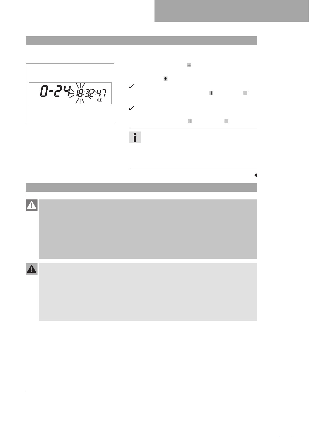
3.33 Adjusting the clock
400330-01
SERVICE WORK ON THE CHASSIS 3
Condition
The motorcycle is stationary.
– Repeatedly press the button briefly until CLK appears at the
bottom right of the display.
– Press the button for 2–3 seconds.
The hour display flashes.
– Adjust the hour display with the button and/or button .
– Wait 3 - 5 seconds.
The next segment of the display flashes and can be set.
– You can set the following segments in the same way as the
hours by pressing the button and the button .
Info
The seconds can only be set to zero.
If no button is pressed for 15 - 20 seconds, or if an
impulse comes from the wheel speed sensor, the
settings are automatically saved and the setup menu is
closed.
3.34 Refueling
Danger
Fire hazard Fuel is highly flammable.
The fuel in the fuel tank expands when warm and can escape if overfilled.
– Do not refuel the vehicle in the vicinity of open flames or lit cigarettes.
– Switch off the engine for refueling.
– Make sure that no fuel is spilled; particularly not on hot parts of the vehicle.
– If any fuel is spilled, wipe it off immediately.
– Observe the specifications for refueling.
Warning
Danger of poisoning Fuel is poisonous and a health hazard.
– Avoid skin, eye and clothing contact with fuel.
– Immediately consult a doctor if you swallow fuel.
– Do not inhale fuel vapors.
– In case of skin contact, rinse the affected area with plenty of water.
– Rinse the eyes thoroughly with water, and consult a doctor in case of fuel contact with the eyes.
– Change your clothing in case of fuel spills on them.
Note
Material damage Inadequate fuel quality causes the fuel filter to quickly become clogged.
In some countries and regions, the available fuel quality and cleanliness may not be sufficient. This will result in
problems with the fuel system.
– Refuel only with clean fuel that meets the specified standards.
25

3 SERVICE WORK ON THE CHASSIS
Warning
Environmental hazard Improper handling of fuel is a danger to the environment.
– Do not allow fuel to enter the groundwater, the soil, or the sewage system.
Preparatory work
– Switch off the engine.
– Fold the seat up. ( p. 17)
– Open the filler cap. ( p. 26)
Main work
–
Fill the fuel tank with fuel up to measurementA.
Guideline
Measurement of
A
30 mm (1.18 in)
Total fuel tank
capacity, approx.
401474-10
Finishing work
– Close the filler cap. ( p. 27)
– Lock the seat. ( p. 18)
5 l
(1.3 US gal)
3.35 Opening the filler cap
Danger
Fire hazard Fuel is highly flammable.
The fuel in the fuel tank expands when warm and can escape if overfilled.
– Do not refuel the vehicle in the vicinity of open flames or lit cigarettes.
– Switch off the engine for refueling.
– Make sure that no fuel is spilled; particularly not on hot parts of the vehicle.
– If any fuel is spilled, wipe it off immediately.
– Observe the specifications for refueling.
Warning
Danger of poisoning Fuel is poisonous and a health hazard.
– Avoid skin, eye and clothing contact with fuel.
– Immediately consult a doctor if you swallow fuel.
– Do not inhale fuel vapors.
– In case of skin contact, rinse the affected area with plenty of water.
– Rinse the eyes thoroughly with water, and consult a doctor in case of fuel contact with the eyes.
– Change your clothing in case of fuel spills on them.
– Keep fuels correctly in a suitable canister, and out of the reach of children.
Super unleaded
(ROZ 95/RON
95/PON 91)
( p. 30)
Warning
Environmental hazard Improper handling of fuel is a danger to the environment.
– Do not allow fuel to enter the groundwater, the soil, or the sewage system.
Preparatory work
– Fold the seat up. ( p. 17)
26

3.36 Closing the filler cap
E00979-10
SERVICE WORK ON THE CHASSIS 3
Main work
–
Press release button1, turn the filler cap counterclockwise,
and lift it free.
Main work
– Replace the filler cap and turn clockwise until the release but-
ton1locks in place.
Info
Run the fuel tank breather hose2without kinks.
E00978-10
Finishing work
– Lock the seat. ( p. 18)
27

4 TECHNICAL DATA
4.1 Chassis tightening torques
Screw for spoiler, top EJOT PT®K60x20AL 3 Nm (2.2 lbf ft)
Screw, front spoiler EJOT PT®K60x30‑Z 3 Nm (2.2 lbf ft)
Screw, pressure regulator EJOT PT®K60x25-Z 2 Nm (1.5 lbf ft)
Screw, fixed grip M4 5 Nm (3.7 lbf ft)
Spoke nipple M4.5 6 Nm (4.4 lbf ft)
Screw, battery terminal M5 2.5 Nm (1.84 lbf ft)
Screw, intake air temperature sen-
sor
Screw, shock absorber adjusting
ring
Screws on the main silencer M5 7 Nm (5.2 lbf ft)
Nut, cable on starter motor M6 4 Nm (3 lbf ft)
Remaining nuts, chassis M6 10 Nm (7.4 lbf ft)
Remaining screws, chassis M6 10 Nm (7.4 lbf ft)
Screw for spoiler attachment M6 5 Nm (3.7 lbf ft)
Screw, ball joint of push rod on
foot brake cylinder
Screw, engine guard M6x20 10 Nm (7.4 lbf ft)
Screw, engine guard M6x12 10 Nm (7.4 lbf ft)
Screw, foot brake cylinder M6 10 Nm (7.4 lbf ft)
Screw, front brake disc M6 14 Nm (10.3 lbf ft)
Screw, radiator bracket M6 7 Nm (5.2 lbf ft)
Screw, rear brake disc M6 14 Nm (10.3 lbf ft)
Screws, throttle grip M6 5 Nm (3.7 lbf ft)
Fuel connection on fuel pump M8 10 Nm (7.4 lbf ft)
Nut, foot brake lever stop M8 20 Nm (14.8 lbf ft)
Nut, rear sprocket screw M8 35 Nm (25.8 lbf ft)
Nut, rim lock M8 10 Nm (7.4 lbf ft)
Remaining nuts, chassis M8 25 Nm (18.4 lbf ft)
Remaining screws, chassis M8 25 Nm (18.4 lbf ft)
Screw of rear brake caliper M8 25 Nm (18.4 lbf ft)
Screw, bottom triple clamp M8 18 Nm (13.3 lbf ft)
Screw, chain sliding piece M8 15 Nm (11.1 lbf ft)
Screw, engine brace on cylinder
head
Screw, engine brace on frame M8 25 Nm (18.4 lbf ft)
Screw, fork stub M8 15 Nm (11.1 lbf ft)
Screw, front brake caliper M8 25 Nm (18.4 lbf ft)
Loctite®243™
M5 2 Nm (1.5 lbf ft)
M5 5 Nm (3.7 lbf ft)
M6 10 Nm (7.4 lbf ft)
Loctite®243™
Loctite®243™
Loctite®243™
Loctite®243™
Loctite®2701™
Loctite®243™
M8 25 Nm (18.4 lbf ft)
Loctite®2701™
Loctite®2701™
Loctite®243™
28

Screw, fuel tank M8 15 Nm (11.1 lbf ft)
Screw, handlebar clamp M8 20 Nm (14.8 lbf ft)
Screw, main silencer M8x20 25 Nm (18.4 lbf ft)
Screw, main silencer M8x25 25 Nm (18.4 lbf ft)
Screw, side stand attachment M8 25 Nm (18.4 lbf ft)
Screw, subframe M8 30 Nm (22.1 lbf ft)
Screw, top steering stem M8 17 Nm (12.5 lbf ft)
Screw, top triple clamp M8 22 Nm (16.2 lbf ft)
Engine bracket screw M10 60 Nm (44.3 lbf ft)
Nut, fuel tank attachment M10 10 Nm (7.4 lbf ft)
Remaining nuts, chassis M10 45 Nm (33.2 lbf ft)
Remaining screws, chassis M10 45 Nm (33.2 lbf ft)
Screw, battery compartment M10 45 Nm (33.2 lbf ft)
Screw, cross bar M10 45 Nm (33.2 lbf ft)
Screw, foot brake lever M10 30 Nm (22.1 lbf ft)
Screw, footrest bracket M10 45 Nm (33.2 lbf ft)
Screw, handlebar support M10 40 Nm (29.5 lbf ft)
Screw, upper subframe M10 45 Nm (33.2 lbf ft)
Nut, fuel pump fixation M12 15 Nm (11.1 lbf ft)
Screw, bottom shock absorber M12 80 Nm (59 lbf ft)
Screw, top shock absorber M12 80 Nm (59 lbf ft)
Nut, swingarm pivot M14x1.5 75 Nm (55.3 lbf ft)
Nut, rear wheel spindle M20x1.5 80 Nm (59 lbf ft)
Screw, front wheel spindle M20x1.5 35 Nm (25.8 lbf ft)
Screw, top steering head M20x1.5 12 Nm (8.9 lbf ft)
TECHNICAL DATA 4
Loctite®243™
Loctite®2701™
Loctite®243™
Loctite®243™
Loctite®243™
Loctite®243™
Loctite®243™
Loctite®243™
Loctite®2701™
Loctite®2701™
29

5 SUBSTANCES
Super unleaded (ROZ 95/RON 95/PON 91)
Standard/classification
– DIN EN 228 (ROZ 95/RON 95/PON 91)
Guideline
– Only use unleaded super fuel that matches or is equivalent to the specified fuel grade.
– Fuel with an ethanol content of up to 10 % (E10 fuel) is safe to use.
Info
Do not use fuel containing methanol (e. g. M15, M85, M100) or more than 10 % ethanol (e. g. E15,
E25, E85, E100).
30

Long-life grease
Recommended supplier
®
Motorex
– Bike Grease 2000
AUXILIARY SUBSTANCES 6
31

*3213743en*
3213743en
08/2017
KTM Sportmotorcycle GmbH
5230 Mattighofen/Austria
http://www.ktm.com
Photo: Mitterbauer/KTM
 Loading...