


SETUP INSTRUCTIONS 2016
Freeride E‑SM
Art. no. 3213505en


INTRODUCTION 1
INTRODUCTION
The work described in these setup instructions must be performed before the vehicle is delivered to the customer.
Read the setup instructions in their entirety before beginning work.
These setup instructions were written to correspond to the latest state of this series. We reserve the right to make changes in the interest
of technical advancement without at the same time updating this manual.
We shall not provide a description of general workshop methods. Likewise, safety rules that apply in a workshop are not specified here. It
is assumed that the work will be performed by a fully trained mechanic with the corresponding HV training.
All specifications are non-binding. KTM Sportmotorcycle GmbH specifically reserves the right to modify or delete technical specifications,
prices, colors, forms, materials, services, designs, equipment, etc., without prior notice and without specifying reasons, to adapt these to
local conditions, as well as to stop production of a particular model without prior notice. KTM accepts no liability for delivery options, deviations from illustrations and descriptions, misprints, and other errors. The models portrayed partly contain special equipment that does not
belong to the regular scope of supply.
© 2016 KTM Sportmotorcycle GmbH, Mattighofen Austria
All rights reserved
Reproduction, even in part, as well as copying of all kinds, is permitted only with the express written permission of the copyright owner.
ISO 9001(12 100 6061)
According to the international quality management standard ISO 9001, KTM uses quality assurance processes that lead to
the maximum possible quality of the products.
Issued by: TÜV Management Service
KTM Sportmotorcycle GmbH
5230 Mattighofen, Austria
This document is valid for the following models:
Freeride E-SM EU (F3001P2)
*3213505en*
3213505en
03/2016

1 MEANS OF REPRESENTATION 2
1.1 Symbols used
The meaning of specific symbols is described below.
Indicates an expected reaction (e.g. of a work step or a function).
Indicates an unexpected reaction (e.g. of a work step or a function).
Indicates work requiring expert knowledge and technical understanding. In the interest of your own safety, only
have these jobs performed by correspondingly trained KTM technical personnel.
All work identified by this symbol requires a level 1 qualification for high-voltage systems. Only this qualification
authorizes you to perform non-electro-technical work on a vehicle or on units with a high-voltage system.
All work identified by this symbol requires a level 2 qualification for high-voltage systems. Only this qualification
authorizes you to de-energize the electrical system and perform electro-technical work in a de-energized state.
All work identified by this symbol requires a level 3 qualification for high-voltage systems. Only this qualification
authorizes you to perform electro-technical work under voltage.
Indicates a page reference (more information is provided on the specified page).
Indicates information with more details or tips.
Indicates the result of a testing step.
Indicates a voltage measurement.
Indicates a current measurement.
Indicates a resistance measurement.
1.2 Formats used
The typographical formats used in this document are explained below.
Proprietary name Indicates a proprietary name.
®
Name
Brand™ Indicates a brand available on the open market.
Underlined terms Refer to technical details of the vehicle or indicate technical terms, which are explained
Indicates a protected name.
in the glossary.

2 SAFETY ADVICE 3
2.1 Work rules
The KTM PowerPack does not contain any parts that require maintenance. Do not open the KTM PowerPack under any circumstances.
Special tools are necessary for certain tasks. The tools are not a component of the vehicle, but can be ordered using the number in
parentheses. Example: transmission shaft holder (70029032000)
During assembly, non-reusable parts (e.g. self-locking screws and nuts, seals and seal rings, O-rings, pins, lock washers) must be
replaced by new parts.
In some instances, a thread locker (e.g. Loctite®) is required. The manufacturer instructions for use must be followed.
After disassembly, clean the parts that are to be reused and check them for damage and wear. Change damaged or worn parts.
After you complete the repair or service work, check the operating safety of the vehicle.
2.2 Safety advice
A number of safety instructions need to be followed to operate the vehicle safely. Therefore, read this manual carefully. The safety
instructions are highlighted in the text and are referred to at the relevant passages.
Info
The vehicle has various information and warning labels at prominent locations. Do not remove information/warning labels. If
they are missing, you or others may not recognize dangers and may therefore be injured.
2.3 Degrees of risk and symbols
Warning
Indicates a danger that is likely to lead to fatal or serious injury if the appropriate measures are not taken.
Caution
Indicates a danger that may lead to minor injuries if the appropriate measures are not taken.
Note
Indicates a danger that will lead to considerable machine and material damage if the appropriate measures are not taken.
Warning
Indicates a danger that will lead to environmental damage if the appropriate measures are not taken.
2.4 Operating and auxiliary substances
Use the operating and auxiliary substances (such as oils and lubricants) specified in the Owner's Manual.
2.5 Fire hazard
Warning
Fire hazard Damaged rechargeable lithium-ion batteries (KTM PowerPacks) present a fire hazard.
Massive mechanical damage may cause an internal cell short circuit and cause the battery to self-ignite.
– Contact the KTM customer service immediately if major damage to the rechargeable lithium-ion battery (KTM PowerPack)
has occurred.
There is no particular fire hazard for this vehicle when the rechargeable lithium-ion battery (KTM PowerPack) is intact.
However, should the vehicle catch fire, inform the fire brigade responsible that an electric vehicle with a rechargeable lithium-ion battery is on fire.

3 SETUP 4
0
0
0
0
3.1 Unpacking and setting up the vehicle
– Remove the box and the plastic packaging.
Info
An assistant prevents the motorcycle from falling over.
To avoid damaging the motorcycle during the setup, leave the protective
film on the vehicle until you have finished.
– Remove the separate enclosure and unpack it. Check that the scope of supply is
complete on the basis of the enclosed packing list.
C00858-10
– To be in compliance with the homologation of the vehicle, mount all of the parts in
the separate enclosure when assembling the vehicle.
Info
It is not necessary to mount all of the parts in the separate enclosure for the
vehicle to operate correctly. However, homologation will not apply if not all
parts from the separate enclosure are mounted.
– Remove the KTM PowerPack. ( p. 17)
– Have a lift stand available.
Lift stand (54829055000)
– Carefully loosen and remove the tension belt of the footrest bracket.
402050-01
C00761-10
Info
An assistant prevents the motorcycle from falling over.
– Together with an assistant, take the vehicle off the palette.
– Position the vehicle on a lift stand.
– Check the vehicle for transport damage.
–
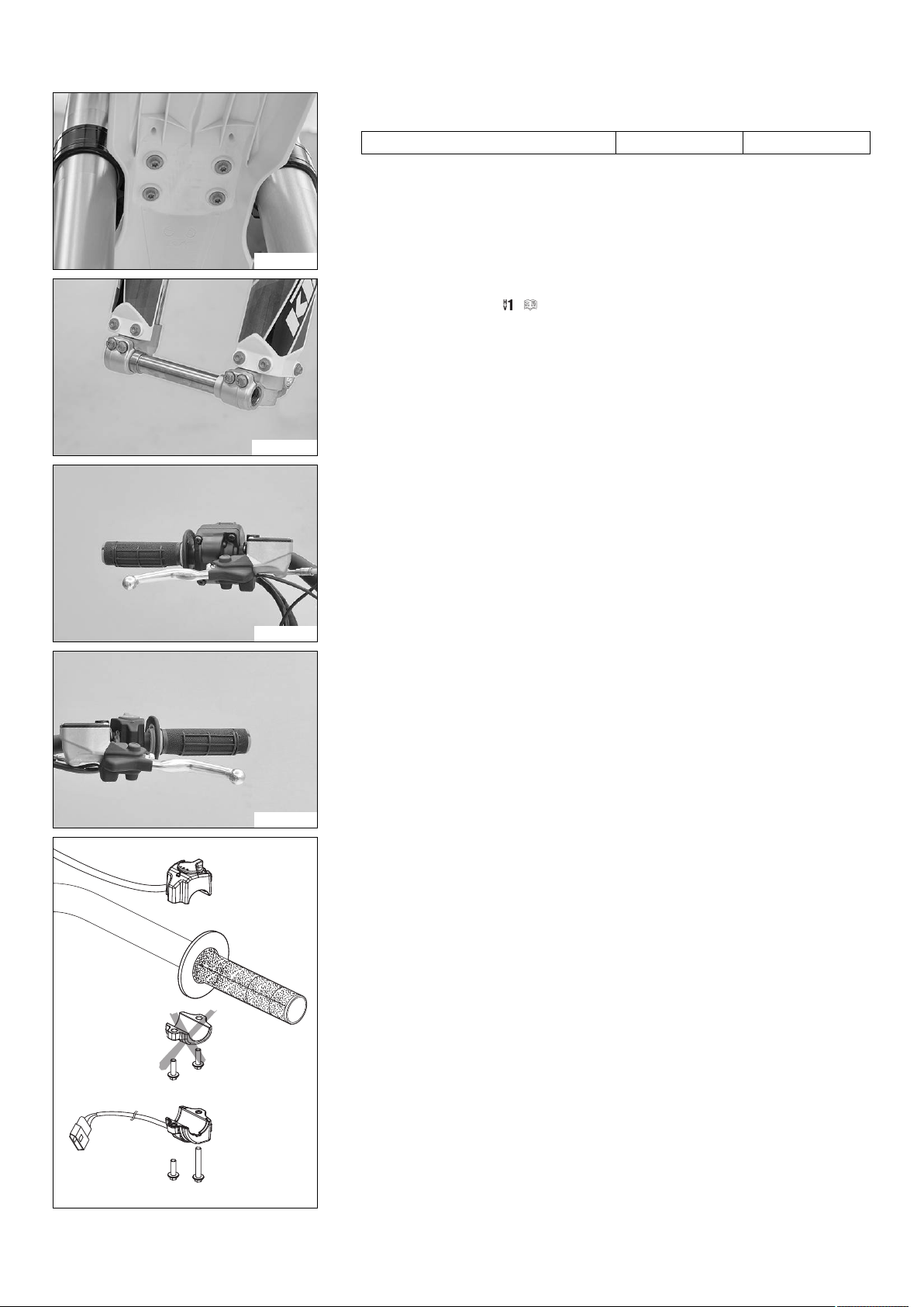
Remove screws. Take off the handlebar clamps.
–
Remove screws. Take off the handlebar supports.
– Place the handlebar supports in the required position. Mount and tighten
screws.
Guideline
Screw, handlebar support M10 40 Nm
(29.5 lbf ft)
Loctite®243™
Info
Position the left and right handlebar supports evenly.
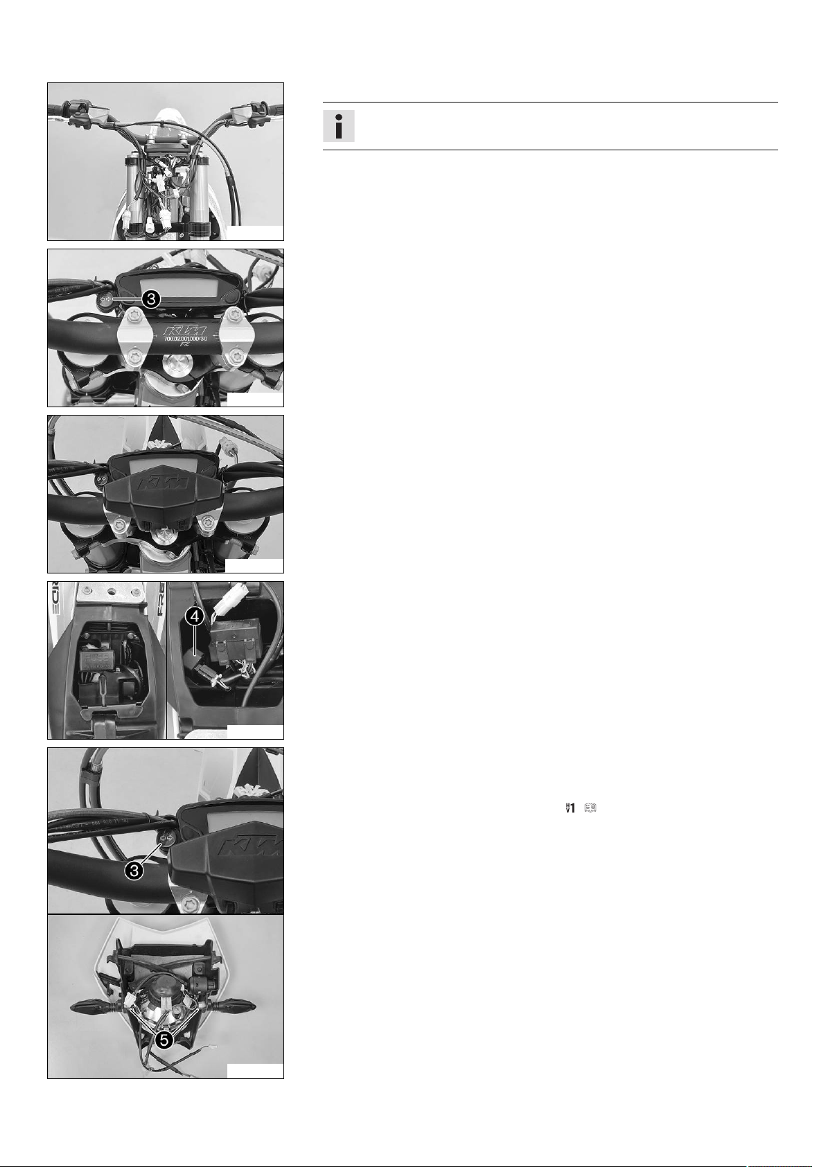
– Position the handlebar.
Info
Make sure the cables and wiring are positioned correctly.
– Position the handlebar clamps. Mount and tighten the screws evenly.
Guideline
Screw, handlebar clamp M8 20 Nm
(14.8 lbf ft)
C00860-01
Info
The markings on the handlebar should be at the center of the handlebar
clamps.
Keep the gap widths equal when tightening.
3 SETUP 5
– Position the front fender and mount and tighten the screws.
Guideline
Remaining screws, chassis M6 10 Nm (7.4 lbf ft)
C00867-01
– Release the axle clamp screws and remove the wheel spindle.
– Install the front wheel. ( p. 11)
M00696-01
– Position the controls on the right half of the handlebar.
C00863-01
C00864-01
– Position the controls on the left half of the handlebar.
– Mount the turn signal switch and connect the plug-in connector on the wiring har-
ness.
402390-01
3 SETUP 6
– Connect all plug-in connectors to the connector retainer.
Info
Make sure the cables and wiring are positioned correctly.
C00865-01
–
Position turn signal indicator lamp.
C00866-10
– Mount the handlebar cushion.
M00697-01
C00868-10
– Take off the electrical compartment.
–
Connect turn signal relay.
– Route the wiring harness for the rear turn signal and license plate lamp and con-
nect the electrical consumers.
– Mount the electrical compartment.
– Insert the black and violet cables of the bulb included in the separate enclosure
into the socket and position it in the turn signal indicator lamp.
–
Position the turn signal on each side and mount and tighten nuts.
– Refit the headlight mask with the headlight. ( p. 20)
S01177-10

3 SETUP 7
– Mount the footrests with the springs and pins. Secure the pins using the washers
and cotter pins.
Pliers for footrest spring (58429083000)
M00695-01
– Mount the license plate holder with the license plate lamp, turn signals, and reflec-
tor.
– Connect the electrical components.
Info
The cable of the left turn signal is marked red.
The cable of the right turn signal is marked green.
S01178-01
– Recharge the 12 V battery. ( p. 16)
– Install the 12 V battery. ( p. 20)
– Unpack and mount the KTM PowerParts included in the delivery (optional).
C00740-01
M00700-01
Info
Read the accompanying KTM PowerParts fitting instructions.
– Apply the label included in the delivery (optional).
– Mount the mirror clamps on both sides.
– Mount and tighten the rear mirror on both sides.
M01438-01
C00869-10
Note
Material damage The ferrite core has a one-way lock.
If the locked ferrite core is reopened, the lock is destroyed.
– Before installing the ferrite core, ensure it is properly positioned.
–
Remove screw.
Info
The screw can be reached through a drill hole in the motor cover.
 Loading...