

Page 1
BEDIENUNGSANLEITUNG2005
OWNER’S MANUAL
MANUALE D’USO
MANUEL D’UTILISATION
MANUAL DE INSTRUCCIONES
ART. NR. 3.211.51
950 ADVENTURE
950 ADVENTURE S
Page 2
ENGLISH
1
IMPORTANT »
Please insert the serial numbers of your motorcycle in the boxes below
Frame number
Engine number
Key number
Stamp of dealer
All information contained is without obligation. KTM-Sportmotorcycle AG particularly reserves the right
to modify any equipment, technical specifications, prices, colors, shapes, materials, services, service work,
constructions, equipment and the like so as to adapt them to local conditions or to cancel any of the above
items, all without previous announcement and without giving reasons. KTM may stop manufacturing certain models without previous notice. KTM shall not be held liable for any deviations of availability and/or
ability to deliver, illustrations, descriptions, printing and/or other errors. The illustrated models partly contain extra equipment, which is not applied to standard models.
© 2004 by KTM-SPORTMOTORCYCLE AG, Mattighofen AUSTRIA; All rights reserved; Reprint, also in
extracts, with written allowance of KTM-SPORTMOTORCYCLE AG, Mattighofen only.
COMSUMER INFORMATION FOR AUSTRALIA ONLY
Tampering with noise control system prohibited
Owners are warned that the law may prohibit:
(a) The removal or rendering inoperative by any person other than for purposes of maintenance, repair or
replacement, of any device or element of design incorporated into any new vehicle for the purpose of
noise control prior to its sale or delivery to the ultimate purchaser or while it is in use; and
(b) the use of the vehicle after such device or element of design has been removed or rendered inopera-
tive by any person.
We strongly suggest that you read this manual carefully and completely before going on your first ride.
It contains a great deal of information and advice which will help you use and handle your bike properly.
In your own interest, please pay particular attention to notices that are marked as follows:
– IGNORING THESE INSTRUCTIONS, CAN ENDANGER YOUR BODY AND YOUR LIFE.
– IGNORING THESE INSTRUCTIONS COULD CAUSE DAMAGE TO PARTS OF YOUR MOTORCYCLE OR THAT
THE MOTOR-CYCLE IS NOT ROAD-SAFE ANYMORE.
Page 3

ENGLISH
2
INTRODUCTION »
We would like to congratulate you on your purchase of a KTM motorcycle.
You are now the owner of a state-of-the-art sport motorcycle that guarantees to bring you lots of fun and
enjoyment, provided that you clean and maintain it appropriately. Before you go for your first ride, be sure
to read this manual carefully and thoroughly in order to familiarize yourself with how to operate your new
motorcycle and with its characteristics, even if this means that you will have to dedicate some of your
valuable time to this task. Only by doing so will you learn how to tune your motorcycle to your specific
needs and how to protect yourself against injury. Besides, this manual contains important information on
motorcycle maintenance. At the time this manual was typeset, it was up-to-date with the latest state of
this production series. It cannot be completely ruled out, however, that minor discrepancies may exist
resulting from further design upgrades of these motorcycles.This manual is an important part of your motorcycle and should be passed on to any subsequent owner in case you decide to sell it.
We expressly point out that work marked with an asterisk in the chapter "Maintenance work on the chassis and engine" must be performed by an authorized KTM workshop If maintenance work should become
necessary during a competition it should be performed by a trained mechanic. KTM strongly recommends
that all service work to your KTM should be performed by a qualified KTM dealer.
The designations "left, right, front, rear“ always refer to the direction of travel.
For your own safety, use KTM-approved parts and accessories only. KTM is not liable for damage that
arises in connection with the use of other products.
Take special care to follow the recommended run in, inspection, and maintenance intervals. Heeding
these guidelines will significantly increase the life of your motorcycle.
Off-road motorcycle driving is a wonderful sport and we hope that you will be able to enjoy it to the full.
It may, however, involve potential problems for the environment or lead to conflicts with others. These
problems or conflicts can be avoided if the motorcycle is used responsibly. To safeguard the future of
motorcycle sports, make sure that you use the motorcycle in accordance with the law, show that you are
environmentally conscious and respect the rights of others.
We wish you a lot of fun when driving !
KTM SPORTMOTORCYCLE AG
5230 MATTIGHOFEN, AUSTRIA
Page 4

ENGLISH
3
IMPORTANT LIMITED WARRANTY AND LIMITED GUARANTEE INFORMATION »
The KTM 950 Adventure models are designed to withstand normal use on roads and easy terrain
(unpaved roads).
The service, care and operating instructions for the engine and chassis specified in the owner's manual
must be observed to ensure that the bike runs smoothly and to avoid premature wear.
The service work described in the "Lubrication and maintenance schedule“ must be performed by an
authorized KTM workshop that can verify having attended the respective training programs. Only these
workshops will have trained personnel qualified to service the 950 Adventure. The service work must be
recorded in the service manual, otherwise the warranty will become null and void.
The fuels and lubricants specified in the owner's manual or those of an equal quality must be used in
accordance with the maintenance schedule.
The warranty or guarantee shall become void for damage and consequential damage caused by manipulations or conversions to the motorcycle.
The use of the motorcycle under extreme conditions, e.g. on extremely muddy and wet terrain, can lead
to higher than average wear on components such as the drive train or the brakes. In this case it may
become necessary to service or replace wear parts before the service limit specified in the maintenance
schedule has been reached.
In accordance with the international quality management ISO 9001 standard, KTM uses
quality assurance processes that lead to the highest possible product quality.
Page 5

ENGLISH
4
INDEX »
Page
SERIAL NUMBER LOCATIONS . . . . . . . . . . . . . . . . . . . .5
Chassis number . . . . . . . . . . . . . . . . . . . . . . . . . . . .5
Engine number, engine type . . . . . . . . . . . . . . . . . . .5
OPERATION INSTRUMENTS . . . . . . . . . . . . . . . . . . . . .5
Clutch lever . . . . . . . . . . . . . . . . . . . . . . . . . . . . . . .5
Choke lever . . . . . . . . . . . . . . . . . . . . . . . . . . . . . . . .5
Hand brake lever . . . . . . . . . . . . . . . . . . . . . . . . . . .5
Multi-functional digital speedometer . . . . . . . . . . . . . .6
Display . . . . . . . . . . . . . . . . . . . . . . . . . . . . . . . . . . .6
Setting options in the display . . . . . . . . . . . . . . . . . . .7
Cooling liquid temperature display . . . . . . . . . . . . . . .8
Indicator lamps . . . . . . . . . . . . . . . . . . . . . . . . . . . .8
Tachometer . . . . . . . . . . . . . . . . . . . . . . . . . . . . . . .8
Ignition lock . . . . . . . . . . . . . . . . . . . . . . . . . . . . . .9
Combination switch . . . . . . . . . . . . . . . . . . . . . . . . .9
Emergency OFF tip switch, light switch, starter tip switch
. .9
Storage compartment . . . . . . . . . . . . . . . . . . . . . . .10
Filler caps . . . . . . . . . . . . . . . . . . . . . . . . . . . . . . .10
Seat lock . . . . . . . . . . . . . . . . . . . . . . . . . . . . . . . .10
Fuel taps . . . . . . . . . . . . . . . . . . . . . . . . . . . . . . . .10
Shift lever . . . . . . . . . . . . . . . . . . . . . . . . . . . . . . .11
Side stand . . . . . . . . . . . . . . . . . . . . . . . . . . . . . . .11
Center stand . . . . . . . . . . . . . . . . . . . . . . . . . . . . . .11
Foot brake pedal . . . . . . . . . . . . . . . . . . . . . . . . . . .11
Compression damping of fork . . . . . . . . . . . . . . . . . .11
Rebound damping of fork . . . . . . . . . . . . . . . . . . . .12
Spring preload of the fork . . . . . . . . . . . . . . . . . . . .12
Damping action during compression of shock absorber . .12
Rebound damping of shock absorber . . . . . . . . . . . .12
Shock absorber's preload adjuster . . . . . . . . . . . . . . .13
Baggage carrier plate . . . . . . . . . . . . . . . . . . . . . . . .13
Grips . . . . . . . . . . . . . . . . . . . . . . . . . . . . . . . . . . .13
Footrests . . . . . . . . . . . . . . . . . . . . . . . . . . . . . . . .13
GENERAL TIPS AND WARNINGS FOR STARTING
THE MOTORCYCLE . . . . . . . . . . . . . . . . . . . . . . . . . . .14
Instructions for initial operation . . . . . . . . . . . . . . .14
Running in the LC8 engine . . . . . . . . . . . . . . . . . . .14
Accessories and payload . . . . . . . . . . . . . . . . . . . . .14
DRIVING INSTRUCTIONS . . . . . . . . . . . . . . . . . . . . . .15
Check the following before each start . . . . . . . . . . .15
Starting when the engine is cold . . . . . . . . . . . . . . .16
Starting when the engine is warm or hot . . . . . . . . .16
Braking . . . . . . . . . . . . . . . . . . . . . . . . . . . . . . . . .17
Stopping and parking . . . . . . . . . . . . . . . . . . . . . . .17
Starting off . . . . . . . . . . . . . . . . . . . . . . . . . . . . . .17
Shifting/Riding . . . . . . . . . . . . . . . . . . . . . . . . . . . .17
Fuel . . . . . . . . . . . . . . . . . . . . . . . . . . . . . . . . . . . .18
PERIODIC MAINTENANCE SCHEDULE . . . . . . . . . . . . .20
MAINTENANCE WORK ON CHASSIS AND ENGINE . . . .22
Removing and remounting the seat . . . . . . . . . . . . .22
Tool set . . . . . . . . . . . . . . . . . . . . . . . . . . . . . . . . .22
Adjusting the fork and shock absorber . . . . . . . . . .23
Adjusting compression damping of fork . . . . . . . . . .23
Adjusting rebound damping of fork . . . . . . . . . . . . .23
Adjusting the spring preload on the fork . . . . . . . . . .23
Compression damping of shock absorber . . . . . . . . .24
Rebound damping of shock absorber . . . . . . . . . . . .24
Page
Adjusting the preload of the shock absorber . . . . . . .25
Breathing the fork legs . . . . . . . . . . . . . . . . . . . . .25
Cleaning the dust sleeves of the telescopic fork . . . .25
Checking the chain tension . . . . . . . . . . . . . . . . . . .25
Correct chain tension . . . . . . . . . . . . . . . . . . . . . . .26
Chain maintenance . . . . . . . . . . . . . . . . . . . . . . . .26
Checking the chain for wear . . . . . . . . . . . . . . . . . .26
General informations about KTM disc brakes . . . . . .27
Adjusting of free travel at the hand brake lever . . . . .28
Checking of brake fluid level - front brake . . . . . . . .28
Refilling the front brake fluid reservoir . . . . . . . . . . .28
Checking the front brake pads . . . . . . . . . . . . . . . . .28
Changing the basic position of the foot brake lever . .29
Checking rear brake fluid level . . . . . . . . . . . . . . . . .29
Refilling the rear brake fluid reservoir . . . . . . . . . . . .29
Checking the rear brake pads . . . . . . . . . . . . . . . . .29
Dismounting and mounting the front wheel . . . . . . . .30
Dismounting and mounting the rear wheel . . . . . . . . .31
Checking the shock absorption rubbers in the rear hub . . . . .31
Tires, air pressure . . . . . . . . . . . . . . . . . . . . . . . . . .32
Checking spoke tension . . . . . . . . . . . . . . . . . . . . . .32
Battery . . . . . . . . . . . . . . . . . . . . . . . . . . . . . . . . . .32
Demounting and mounting the battery . . . . . . . . . . .33
Charging the battery . . . . . . . . . . . . . . . . . . . . . . . .33
Connecting the battery jumper cable . . . . . . . . . . . .33
Main fuse . . . . . . . . . . . . . . . . . . . . . . . . . . . . . . .34
Fuses for individual current consumers . . . . . . . . . .34
Replacing the headlight lamps . . . . . . . . . . . . . . . . .35
Adjusting the headlight range . . . . . . . . . . . . . . . . . .36
Replacing the brake and tail light bulbs . . . . . . . . . .36
Replacing the flasher bulbs . . . . . . . . . . . . . . . . . .36
Cooling system . . . . . . . . . . . . . . . . . . . . . . . . . . . .37
Checking the cooling liquid level in the compensating tank . .37
Checking the cooling liquid level in the radiator . . . . .38
Bleeding the cooling system . . . . . . . . . . . . . . . . . .38
Changing the original position of the clutch lever . . . .39
Checking the oil level of the hydraulic clutch . . . . . .39
Checking and adjusting the throttle cable play . . . . . .39
Checking and adjusting the choke cable play . . . . . . .40
Adjusting the engine idle speed . . . . . . . . . . . . . . . .40
Engine oil . . . . . . . . . . . . . . . . . . . . . . . . . . . . . . . .40
Checking the engine oil level . . . . . . . . . . . . . . . . .40
Changing the engine oil and the oil filter, cleaning
the oil screen . . . . . . . . . . . . . . . . . . . . . . . . . . . . .41
Activating the ignition curve for low-octane fuel . . . .44
TROUBLE SHOOTING . . . . . . . . . . . . . . . . . . . . . . . . .45
CLEANING . . . . . . . . . . . . . . . . . . . . . . . . . . . . . . . . .47
CONSERVATION FOR WINTER OPERATION . . . . . . . . .47
STORAGE . . . . . . . . . . . . . . . . . . . . . . . . . . . . . . . . . .47
RE-INITIATION AFTER TIME OF STORAGE . . . . . . . . .47
TECHNICAL SPECIFICATIONS - CHASSIS . . . . . . . . . . .48
TECHNICAL SPECIFICATIONS - ENGINE . . . . . . . . . . .50
HEAD WORD INDEX . . . . . . . . . . . . . . . . . . . . . . . . . .52
WIRING DIAGRAM . . . . . . . . . . . . . . . . . . . . . .APPENDIX
CONSUMER INFORMATION USA ONLY . . . . . . .APPENDIX
Page 6
ENGLISH
5
SERIAL NUMBER LOCATIONS »
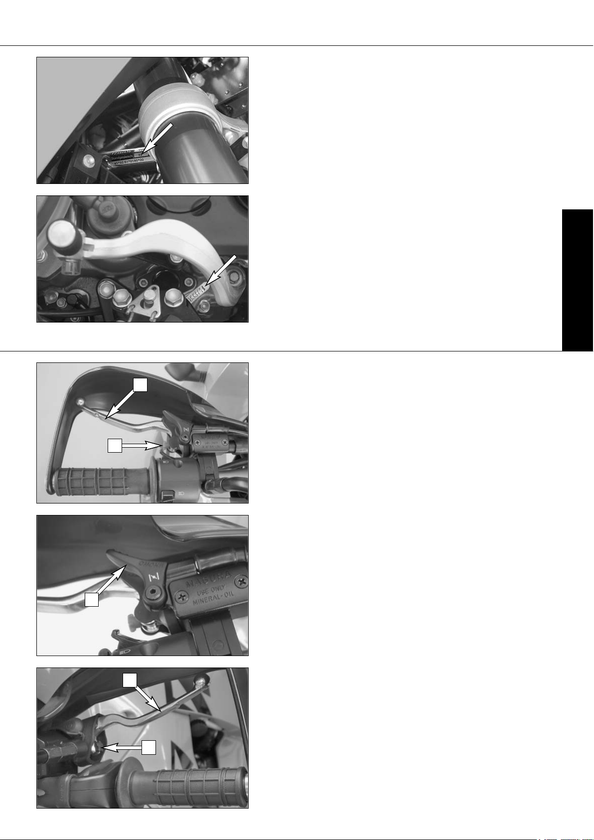
Chassis number
The chassis number is located on the right side of the steering head tube and
on the type label. Write this number into the relevant area on page 1.
Engine number, engine type
The engine number and engine type are embossed in the engine case near
the shift lever. Write this number into the relevant area on page 1.
Clutch lever
The clutch lever [1] is located on the left side of the handlebar. The adjusting screw [A] is used to change the original position of the clutch lever (see
maintenance work on chassis and engine).
The clutch is hydraulically actuated and adjusts itself automatically.
Choke lever
If the choke lever [2] is pulled backwards, a bore in the carburetors will be
opened in the carburetor through which the engine may draw in additional
fuel. This produces a „rich“ fuel/air mixture necessary for cold start. The fuel
quantity and thus the engine speed are determined by the choke lever position.
At temperatures over 5°C (41°F) it will suffice to pull the choke lever half way
out. At temperatures below 5°C (41°F) the choke lever should be pulled all
the way out. The hole is closed again by pushing the choke lever all the way
back in.
Hand brake lever
The hand brake lever [3] is mounted on the handlebars on the right and actuates the front wheel brake. The adjusting screw [B] can be used to change
the basic position of the hand brake lever (see "Maintenance").
OPERATION INSTRUMENTS »
1
2
3
B
A
Page 7
ENGLISH
6
OPERATION INSTRUMENTS »
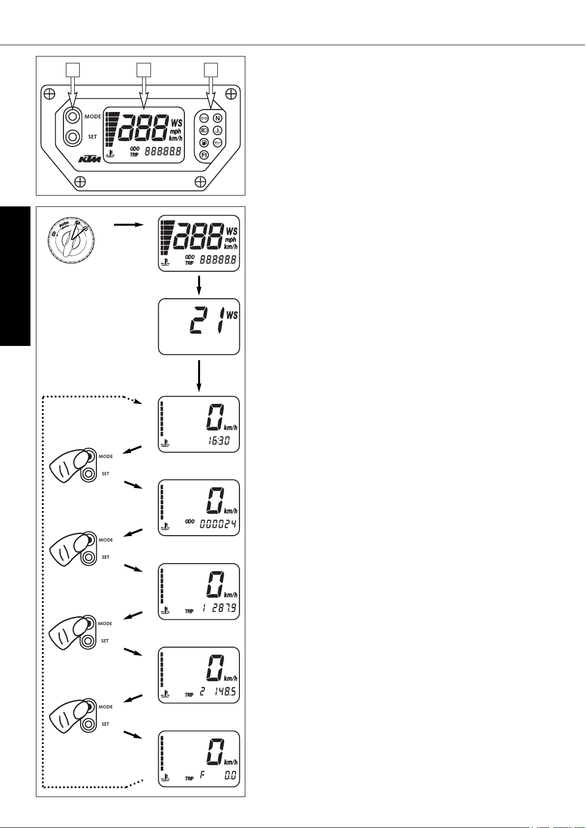
Multi-functional digital speedometer
The universal instrument is divided into 3 parts.
Use the MODE and SET [1] button to change the display and the basic settings in the display.
Display [2] shows all of the information that may be of interest to you.
5 display modes can be selected with the MODE button.
The indicator lamps [3] provide additional information on the motorcycle's
running condition.
Display
TEST
When you switch on the ignition, all of the display elements will light up for
1 second for the function test.
WS (wheel size)
The display will change and show the diameter of the front wheel in inches
for 1 second (WS = wheel size).
Then the CLOCK mode will be displayed, or the mode that was active when
the ignition was switched off.
CLOCK
You will recognize the CLOCK display by the blinking dots between the hours
and minutes. It displays the speed, temperature of the cooling liquid and the
clock.
To switch to the next display mode, press the MODE button.
ODO
The speed, temperature of the cooling liquid and the total kilometers or miles
traveled are shown in the ODO mode.
To switch to the next display mode, press the MODE button.
TRIP 1
The TRIP 1 mode shows the speed, the temperature of the cooling liquid and
the trip odometer 1.
To switch to the next display mode, press the MODE button.
TRIP 2
The TRIP 2 mode shows the speed, the temperature of the cooling liquid and
the trip odometer 2.
To switch to the next display mode, press the MODE button.
TRIP F
The TRIP F (fuel) mode shows the speed, the temperature of the cooling liquid and the distance traveled since reaching the low-fuel mark (the low-fuel
indicator lamp will blink).
To return to the CLOCK mode, press the MODE button.
TEST
WS
ODO
CLOCK
TRIP 1
TRIP 2
TRIP F
1 2 3
Page 8
ENGLISH
7
OPERATION INSTRUMENTS »
Setting options in the display
KILOMETERS OR MILES.
You can have the speed and distance shown in kilometers or miles in the display. The display can be adapted to the respective country on long-distance
trips.
To switch from kilometers to miles, switch on the ignition and press the MODE
[1] button for approx. 10 seconds. The km/h display will switch to mph. The
speed and the stored distances will be converted and displayed in miles.
To return to kilometers, proceed as described above.
CLOCK
Switch on the ignition and change to the CLOCK mode.
Simultaneously press MODE [1] and SET [2]. The numbers on the clock will
start to blink. Use the MODE button to set the hours and the SET button to
set the minutes.
The press the MODE and SET buttons simultaneously.
NOTE:
0:00 will be displayed if the clock is not supplied with electricity. This can
be caused by a defective fuse or a fault in the board electric system (see
Troubleshooting).
TRIP 1
The trip meter 1 runs continuously and counts up to 999.9. It can be used
to measure the length of a certain route on a trip or the distance between two
refueling stops.
To return the trip meter 1 to zero, switch on the ignition, change to the TRIP
1 mode and press the SET button.
RESETTING TRIP 2
The trip meter 2 runs continuously and counts up to 999.9. It can be used
similarly to TRIP 1 or together with a switch available as an accessory (see
below) for trips according to a roadbook.
To return the trip meter 2 to zero, switch on the ignition, change to the TRIP
2 mode and press the SET button.
NOTE
A Tripmaster switch (Part no. 582.14.069.044) is available as an accessory
and enhances the trip meter 2 functions. You can correct the displayed route
by increasing or decreasing in increments of 0.1. For example, if you have
taken the wrong road when driving according to a roadbook, you can easily
correct the display to correspond to the roadbook again. It can also be used
to change the display modes. The switch is mounted on the handlebars so
that you can keep your hands on the handlebars.
TRIP F
When the fuel level reaches the reserve mark, the display will automatically
switch to TRIP F and begin to count (no matter which display mode was active
before). At the same time, the fuel warning lamp will start to blink. You will
still have enough reserve fuel for aprox 50 kilometers (30 miles).
After refueling, it will take approx. 3 minutes for TRIP F to automatically reset
to 0 and return to the previous display mode.
1 10 sec
1
2
2
2
Page 9
ENGLISH
8
OPERATION INSTRUMENTS »
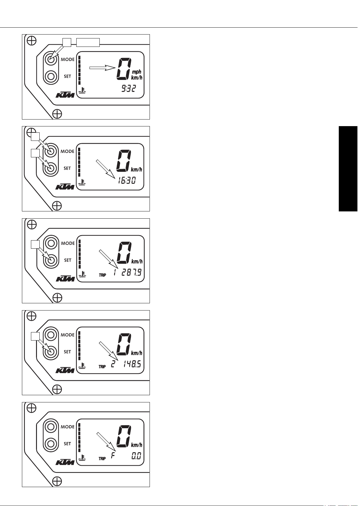
Cooling liquid temperature display
The temperature display [1] is shown in 7 bars. The more bars that light up,
the hotter the cooling liquid. When the lowest bar lights up, the cooling liquid has reached a temperature of approx. 40°C (104°F). When the upper bar
lights up 120°C (248°F), all of the bars will start to blink and the red warning lamp [2] will light up.
POSSIBLE CAUSES FOR AN INCREASE IN TEMPERATURE, CAUSING THE RED
WARNING LIGHT FOR THE COOLING LIQUID TEMPERATURE TO LIGHT UP:
–
DRIVING TOO SLOWLY AND DRIVING WITH A HEAVY LOAD AT HIGH AIR TEMPERATURES
– NOT ENOUGH COOLING LIQUID IN THE SYSTEM
– THE VENTILATOR ON THE RADIATOR IS NOT RUNNING
– IMPROPER USE OF THE CLUTCH WHEN DRIVING SLOWLY
Indicator lamps
The green indicator lamp will blink in the blinker rhythm when the
blinker is switched on.
NOTE:
The indicator lamp will blink slower when a blinker is broken.
The green indicator lamp will light up when the gearbox is in an idling
position.
The blue indicator lamp will light up when the high beams are
switched on.
The red warning light will light up when the cooling liquid has reached
a temperature of approx. 120°C (248°F).
The orange warning light will start to blink when the fuel level has
reached the reserve mark. At the same time the display will automatically change to TRIP F (see TRIP F).
The red warning lamp lights up when the ignition is switched on but
the engine is not running. When the engine is started, the warning
lamp will go out as soon as the oil pressure is high enough.
This indicator lamp has no function.
Tachometer
The tachometer shows the engine speed in revolutions per minute. Do not run
the engine beyond the black mark at 9500 rpm.
The speed limiter will set in at 9600 rpm, drastically reducing the engine
power above this rotational speed.
120°C (248°F)
110°C (230°F)
100°C (212°F)
70°C (158°F)
60°C (140°F)
50°C (122°F)
40°C (104°F)
1
2
Page 10
ENGLISH
9
OPERATION INSTRUMENTS »
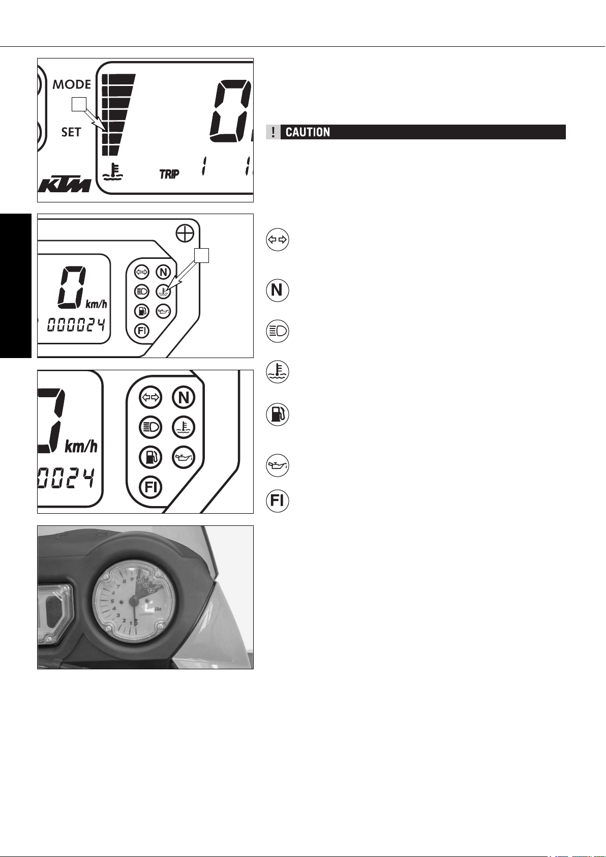
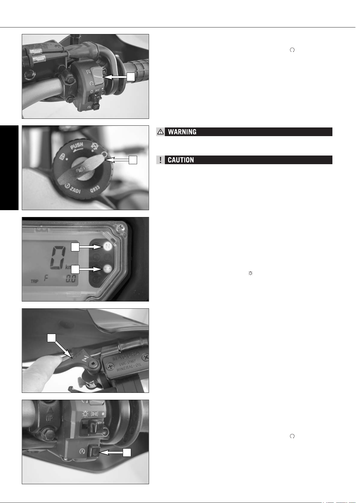
Ignition lock
The ignition lock [1] has 3 switching positions.
Ignition off, (engine can't be started)
Ignition on, (engine can be started)
Ignition off, handlebar blocked
To switch the ignition to position turn the ignition key to position
and firmly press it into the lock. Turn the handlebar all the way to
the left, then turn the ignition key to the left.
The ignition key can be withdrawn in position and .
Combination switch
The rocker switch LIGHTS [2] actuates the high beam or low beam.
= High-beam light
= Low-beam light
The light signal (high beam) is actuated with button [3].
The indicator switch [4] returns to central position after actuation. Press
flasher switch towards switch housing to switch off the flasher.
The horn is sounded with button [5].
Emergency OFF tip switch, light switch, starter tip switch
The emergency off switch [6] is provided for emergency situations and should
not be used to switch off the engine.
The engine is ready for operation in position (ignition circuit and starter
circuit are switched on).
The engine cannot be started in position (ignition circuit and starter circuit are interrupted).
The light switch [7] has 3 positions:
= Light off
= Parking light on
= Headlight on
Use the starter tip switch [8] to operate the electric starter.
1
2
3
2
4
5
6
7
8
Page 11
ENGLISH
10
OPERATION INSTRUMENTS »
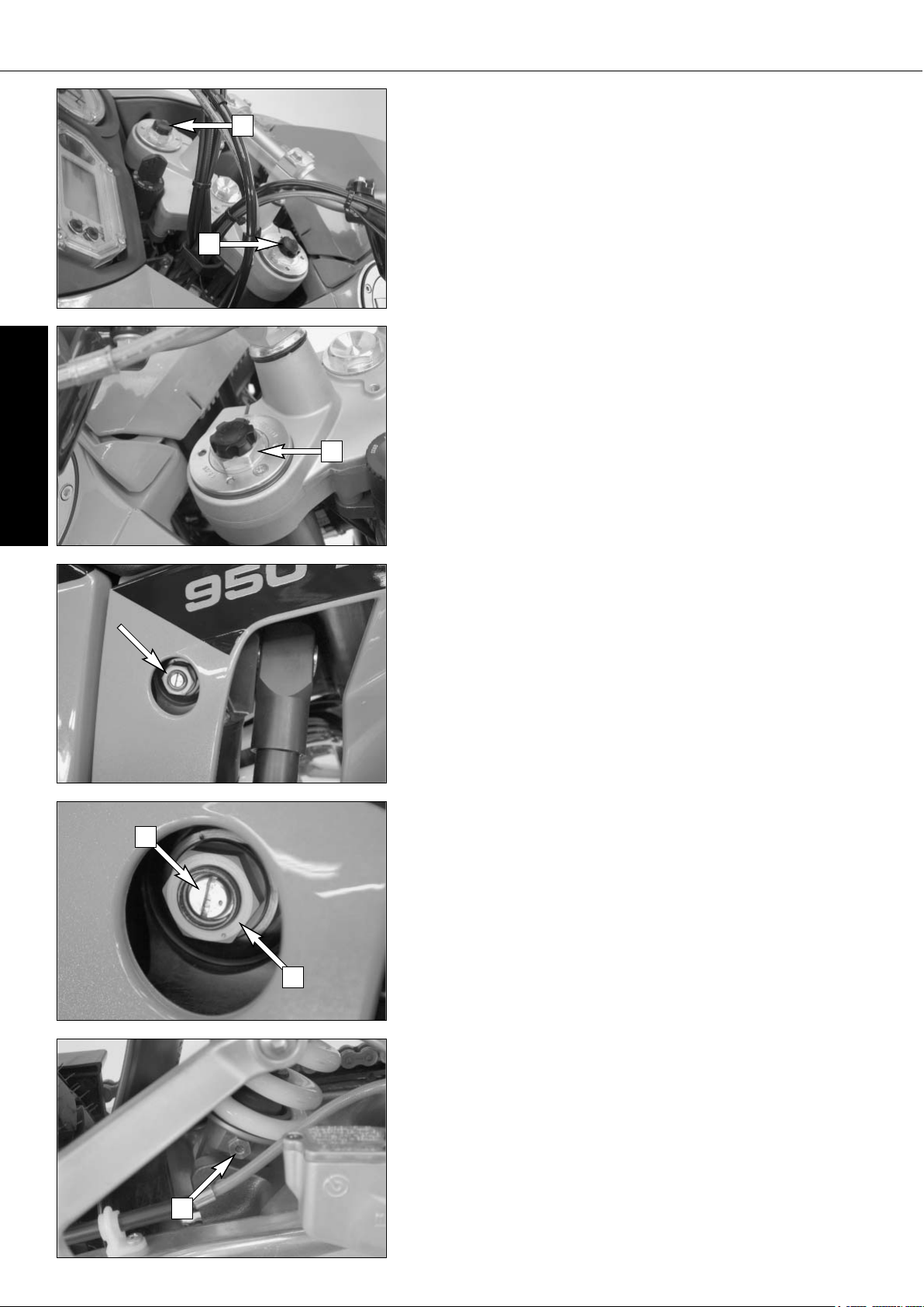
Filler caps
The 950 Adventure has 2 separate fuel tanks.
Both filler caps [2] can be locked and are equipped with a tank vent system.
To open, insert the ignition key, turn 45° in a clockwise direction and fold up
the filler cap.
The ignition key can be pulled out to open the other filler cap. Simply press
on the filler cap to close.
Seat lock
The seat is unlocked by inserting the ignition key in the lock [3] on the side
and turning the key in a counterclockwise direction. See "Maintenance Work"
to remove and remount the seat.
Fuel taps
The 950 Adventure is equipped with 3 fuel taps which only need to be closed
to remove the fuel tank.
Fuel cannot flow to the carburetors if the fuel pump is not running, so the
fuel tap [4] does not need to be closed when the motorcycle is switched off.
Both fuel taps [5] must be open when the motorcycle is running. The level in
the fuel tanks is equalized by means of a connecting hose.
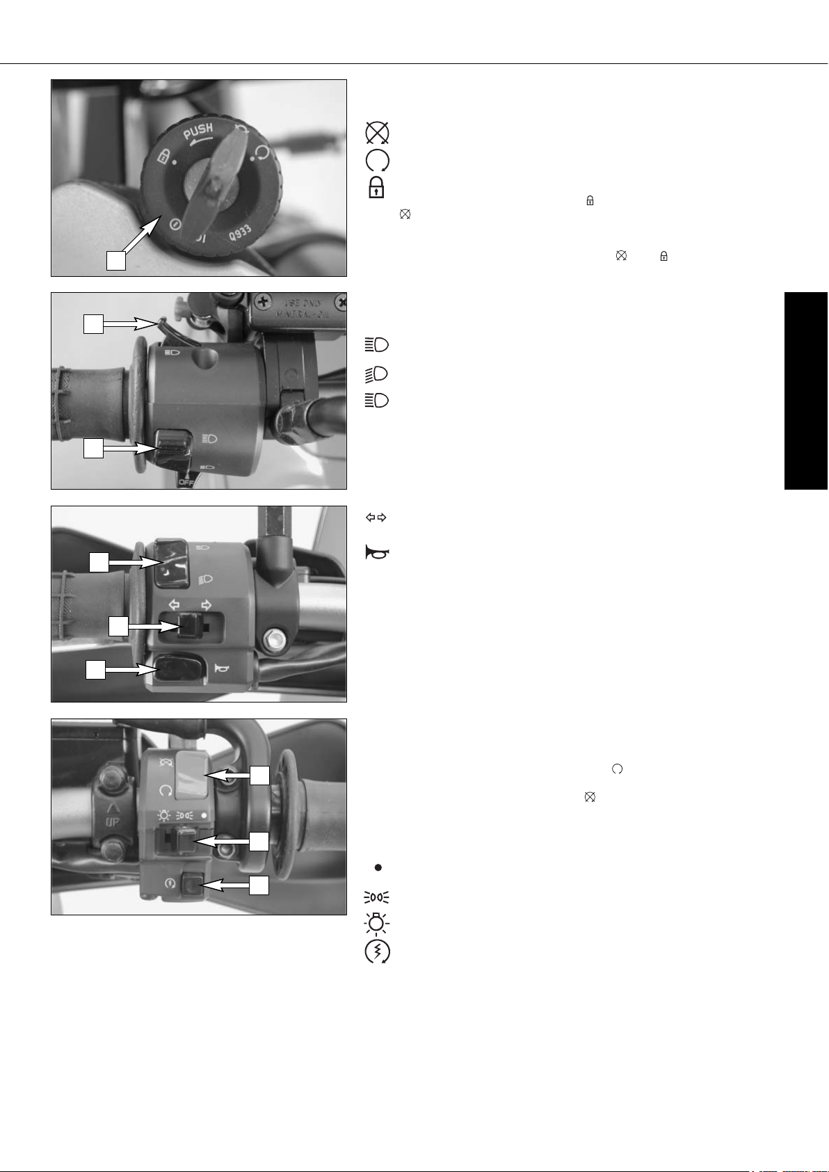
Storage compartment
A storage compartment is located under the seat to hold small, frequently
used items.
To open, turn the quick release [1] approx. 180° in a counterclockwise direction and lift the cover. To lock, close the cover, insert the quick release in the
dolly and turn 180° in a clockwise direction.
1
2
2
3
4
5
5
Page 12
ENGLISH
11
OPERATION INSTRUMENTS »
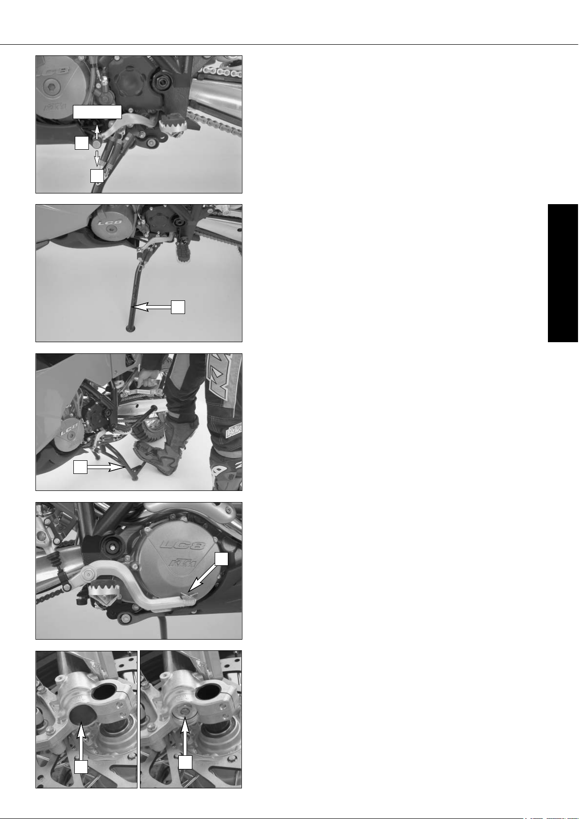
Shift lever
The shift lever is mounted on the left side of the engine. The position of the
gears is shown in the illustration. Neutral, or the idle speed, is located between
first and second gear.
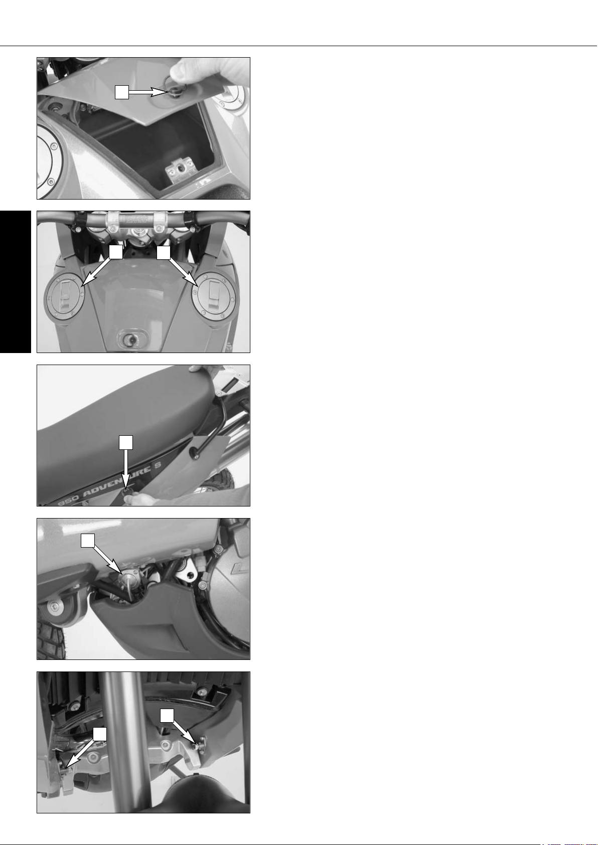
Side stand
The side stand [1] is coupled with a safety starter system. Pay attention to
Driving Instructions.
Center stand
The bike is equipped with a side stand and a center stand [2].
Foot brake pedal
The foot brake pedal [3] is located in front of the right footrest. Its basic
position can be adjusted to your seat position (see maintenance work).
Compression damping of fork
The fork's damping action during compression travel (compression damping)
can be adjusted. This allows you adjust the damping behavior to match your
driving style and the payload.
The adjusting screws [5] are located under the cap [4] on the lower end of
the fork legs.
More information is provided in the chapter "Adjusting the fork and shock
absorber.“
4
5
3
2
1
1
2,3,4,5,6
N
Page 13
ENGLISH
12
OPERATION INSTRUMENTS »
Rebound damping of fork
The fork's damping action during rebound travel (rebound damping) can also
be adjusted. This allows you adjust the damping behavior to match your driving style and the payload.
The adjusting screws [1] are located on the upper end of the fork legs.
More information is provided in the chapter "Adjusting the fork and shock
absorber.“
Spring preload of the fork
The fork's preload can be adjusted by means of the adjusting screws [2].
More information is provided in the chapter "Adjusting the fork and shock
absorber.“
Damping action during compression of shock absorber
The shock absorber's damping action during compression travel (compression
damping) can be adjusted. This allows you adjust the shock absorber's damping behavior to match your driving style and the payload.
The damping rate can be adjusted in the low and high-speed range (Dual
Compression Control). The designation low and high-speed refers to the movement of the shock absorber and not to the motorcycle's driving speed.
The adjusting screw [3] for the low-speed range can be adjusted with a
screwdriver.
The adjusting screw [4] for the high-speed range can be adjusted with a
17 mm socket wrench.
More information is provided in the chapter "Adjusting the fork and shock
absorber.“
Rebound damping of shock absorber
The shock absorber's damping action during rebound travel (rebound damping) can also be adjusted. This allows you adjust the damping behavior to
match your driving style and the payload.
The adjusting screw [5] is located on the bottom of the shock absorber.
More information is provided in the chapter "Adjusting the fork and shock
absorber.“
1
1
2
3
4
5
Page 14
ENGLISH
13
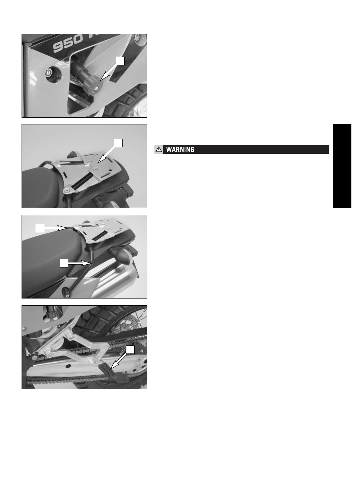
Shock absorber's preload adjuster
The shock absorber's preload adjuster is infinitely variable by means of the
hand wheel [1]. This allows the shock absorber to be adapted to match your
body weight and the payload.
The hand wheel can be swung out to make adjustments.
Baggage carrier plate
The base plate for your choice of case system can be attached to the baggage
carrier plate [2].
– DO NOT LOAD MORE THAN 8 KG ON THE TRUNK CARRIER RACK.
– OBSERVE THE BAGGAGE MANUFACTURER'S INSTRUCTIONS.
Grips
The passenger can hold on to both grab handles [3].
Footrests
The passenger footrests [4] fold up.
OPERATION INSTRUMENTS »
1
2
3
3
4
Page 15
ENGLISH
14
GENERAL TIPS AND WARNINGS FOR STARTING THE MOTORCYCLE »
Instructions for initial operation
– Make sure the work for the „pre-delivery inspection“ was per-
formed by your authorized KTM workshop. The DELIVERY CERTIFICATE and SERVICE MANUAL will be handed over when you
pick up your vehicle.
– Read these operating instructions carefully before your first ride.
– Enter the chassis, engine and key numbers on page 1.
– Familiarize yourself with the operating elements.
– Adjust the hand brake lever and foot brake lever to your most
comfortable position.
– This motorcycle is equipped with 2 catalytic converters.
Leaded fuel will destroy the catalytic converters. Please use
unleaded fuel only.
– Get used to handling the motorcycle on an empty parking lot,
before starting on a longer drive. Also try to drive as slowly as
possible and in standing position, to improve your feeling for
the vehicle.
– Do not drive along off-road tracks which go beyond your abitily
and experience.
– Hold the handlebars with both hands and leave your feet on
the foot rests while driving.
– Remove your foot from the foot brake lever when you are not
braking. If the foot brake lever is not released the brake pads
rub continuously and the braking system is overheated.
– Do not make any alterations to the motorcycle and always use
ORIGINAL KTM SPARE PARTS. Spare parts from other man-
ufacturers can impair the safety of the motorcycle.
– Motorcycles are sensitive to changes in the weight distribution.
Read the section on "Accessories and payload“ when carrying
luggage.
– Pay attention to running-in procedure.
Running in the LC8 engine
Even finely machined surfaces of engine parts have rougher surfaces than parts that slide on each other for a long time. Therefore,
every engine must be run in. For this reason, do not demand maximum performance from the engine for the first 1000 kilometers
(620 miles). The vehicle must be run in at low, changing performance level for the first 1000 km (620 miles). The maximum number of revolutions per minute must not go exceed 6500 rpm. Once
you have run your engine in for 1000 km, you may push it to its
9500 rpm limit , i.e. up to the black zone indicated in the tachometer. Exceeding the above listed rotations as well as pushing high
rpm when the engine is cold will have an adverse effect on the life
of your engine.
– WEAR SUITABLE CLOTHING WHEN DRIVING A MOTORCYCLE.
CLEVER KTM DRIVERS ALWAYS WEAR A HELMET, BOOTS, GLOVES
AND A JACKET, REGARDLESS OF WHETHER DRIVING ALL DAY OR
JUST FOR A SHORT TRIP. THE PROTECTIVE CLOTHING SHOULD BE
BRIGHTLY COLORED SO THAT OTHER VEHICLE CAN SEE YOU AS
EARLY AS POSSIBLE. YOUR PASSENGER WILL ALSO NEED SUIT-
ABLE PROTECTIVE CLOTHING.
– DO NOT DRIVE AFTER HAVING CONSUMED ALCOHOL.
– ALWAYS TURN ON THE LIGHT TO MAKE SURE THAT OTHER DRIV-
ERS BECOME AWARE OF YOU AS EARLY AS POSSIBLE.
– DRIVE AT A MODERATE SPEED FOR THE FIRST FEW KILOMETERS
OF EACH TRIP TO ALLOW THE TIRES TO REACH THE NECESSARY
OPERATING TEMPERATURE. MAXIMUM ROAD GRIP IS ASSURED
WHEN THE TIRES ARE WARM.
– THE FRONT AND REAR WHEEL ARE ALLOWED TO BE FITTED ONLY
WITH TIRES THAT HAVE THE SAME PROFILE TYPE.
– THE TIRES MUST BE DESIGNED FOR A MAXIMUM SPEED OF 240
KPH (SPEED SYMBOL V) AND MUST BE AUTHORIZED BY KTM.
– DO NOT EXCEED THE RESPECTIVE MAXIMUM SPEED FOR TIRES
DESIGNED WITH A SPEED INDEX OF LESS THAN "V“ (240 KPH).
A STICKER SHOWING THE MAXIMUM SPEED MUST BE AFFIXED TO
THE MOTORCYCLE WITHIN THE DRIVER'S FIELD OF VISION.
– NEW WHEELS HAVE A SMOOTH SURFACE, WHICH MEANS THAT THEY
MUST BE RUN IN TO ACHIEVE FULL GRIP. FOR THIS PURPOSE,
RIDE THE MOTORCYCLE CAREFULLY AT MODERATE SPEED DURING THE FIRST 200 KILOMETERS WITH NEW TIRES, TILTING THE
VEHICLE AT DIFFERENT ANGLES SO THAT ALL SECTIONS ARE
PROPERLY ROUGHENED. TIRES WILL NOT DISPLAY THEIR FULL
GRIP CHARACTERISTICS UNTIL THEY ARE PROPERLY RUN IN.
– WHEELS WITH A DIFFERENT RIM DIAMETER OR OTHER RIM WIDTH
MAY NOT BE MOUNTED OTHERWISE THE VEHICLE HANDLING WILL
NO LONGER BE SAFE.
– OBSERVE THE TRAFFIC REGULATIONS, DRIVE DEFENSIVELY AND
TRYING TO LOOK AHEAD AS FAR AS POSSIBLE SO THAT ANY HAZARDS CAN BE RECOGNIZED AS EARLY AS POSSIBLE.
– CHOOSE YOUR DRIVING SPEED ACCORDING TO THE CONDITIONS
AND YOUR DRIVING SKILLS.
– DRIVE CAREFULLY ON UNKNOWN ROADS OR ON UNFAMILIAR
TRIALS.
– RENEW THE VIZOR ON YOUR HELMET OR THE GLASS OF YOUR
GOGGLES ON TIME SO AS TO ENSURE OPTIMUM VISION IN ANY
SITUATION. WHEN LIGHT SHINES DIRECTLY ON SCRATCHED VISOR
OR GOGGLES, THE OPERATOR WILL BE BLINDED.
– NEVER LEAVE YOUR MOTORCYCLE WITHOUT SUPERVISION IF THE
ENGINE IS RUNNING.
Accessories and payload
Accessory parts and baggage can significantly decrease a motorcycle's driving stability. Please observe the following warnings.
– NEVER DRIVE FASTER THAN 130 KPH (80 MPH) IF YOU HAVE
MOUNTED ACCESSORY PARTS ON YOUR MOTORCYCLE. ACCESSORY
PARTS CAN SIGNIFICANTLY IMPAIR THE MOTORCYCLE'S HANDLING, ESPECIALLY IN THE MAXIMUM SPEED RANGE.
– NEVER DRIVE FASTER THAN 130 KPH (80 MPH) IF YOUR MOTOR-
CYCLE IS LOADED WITH CASES OR OTHER BAGGAGE. THEY WILL
IMPAIR THE MOTORCYCLE'S HANDLING AT HIGHER SPEEDS AND
CAN EASILY CAUSE IT TO GO OUT OF CONTROL
– IF YOU HAVE CASES MOUNTED, DO NOT EXCEED THE MANUFAC-
TURER'S RECOMMENDED MAXIMUM PAYLOAD.
– FASTEN THE BAGGAGE CLOSE TO THE CENTER OF THE MOTOR-
CYCLE AND DISTRIBUTE THE WEIGHT EVENLY ON THE FRONT AND
REAR WHEELS AND ON THE LEFT AND RIGHT.
– BAGGAGE MUST BE SECURELY AND ADEQUATELY FASTENEND;
LOOSE BAGGAGE WILL SIGNIFICANTLY IMPAIR DRIVING SAFETY.
– A HIGH PAYLOAD WILL CHANGE THE MOTORCYCLE'S HANDLING
AND CONSIDERABLY INCREASE THE BRAKING DISTANCE; ADAPT
YOUR DRIVING SPEED ACCORDINGLY.
– NEVER EXCEED THE MAXIMUM PERMISSIBLE LADEN WEIGHT AND
THE AXLE WEIGHTS. THE MAXIMUM PERMISSIBLE LADEN WEIGHT
IS MADE UP OF THE FOLLOWING COMPONENTS:
– MOTORCYCLE READY FOR OPERATION AND TANK FULL
– LUGGAGE
–
DRIVER AND PASSENGER WITH PROTECTIVE CLOTHING AND HELMET
Page 16
ENGLISH
15
DRIVING INSTRUCTIONS »
Check the following before each start
When you start, the motorcycle must be in perfect mechanical condition. For
safety reasons, you should make a habit of performing an overall check of
your motorcycle before each start.
The following checks should be performed:
1 FUEL
Check the fuel quantity in the tanks.
2 CHAIN
A loose chain can fall from the chain wheels; an extremely worn chain can
tear, and insufficient lubrication can result in unnecessary wear of chain
and chain wheels.
3 TIRES
Check for damaged tires. Tires showing cuts or dents must be replaced.
The tread depth must comply with the legal regulations. Also check the
air pressure. Insufficient tread and incorrect air pressure deteriorate the
driving performance.
4 BRAKES
Check correct functioning of the braking system. Check for sufficient
brake fluid in the reservoir. The reservoirs have been designed in such a
way that brake fluid does not need to be refilled even when the brake pads
are worn. If the level of brake fluid falls below the minimum value, this
indicates a leak in the braking system or completely worn out brake pads.
Arrange for the braking system to be checked by a KTM specialist, as complete failure of the braking system can be avoided.
Also check the state of the brake hose and the thickness of the brake
linings.
Check free travel at hand brake lever and foot brake lever.
5 CABLES
Check the adjustment and smooth operation of the throttle cables and the
choke cable.
6 COOLING FLUID
Check the level of cooling fluid when the engine is cold.
7 ELECTRICAL SYSTEM
Start the engine and check the headlight, taillight, brake light, turn
signal, indicator lamps and horn for proper functioning.
8 CHECK OIL LEVEL
Insufficient oil results in premature wear and consequently to engine
damage.
9 BAGGAGE, PAYLOAD
Never exceed the maximum total weight (400 kg, 883 lbs) and the motorcycle's wheel loads. The maximum total weight is comprised of:
– the motorcycle in a running condition and refueled (220 kg, 485 lbs)
– the baggage and accessories
– the driver and passenger with protective gear and helmet
Adjust the tire inflation pressure as well as the preload and damping properties of the fork and shock absorber to the total weight.
10 REAR MIRROR
Sit on the motorcycle and check the adjustment of the rear mirror.
NEVER DRIVE FASTER THAN 130 KPH (80 MPH) IF YOUR MOTORCYCLE IS LOADED
WITH CASES OR OTHER BAGGAGE. THEY WILL IMPAIR THE MOTORCYCLE'S HANDLING AT HIGHER SPEEDS AND CAN EASILY CAUSE IT TO GO OUT OF CONTROL.
Page 17
ENGLISH
16
DRIVING INSTRUCTIONS »
Starting when the engine is cold
1 Switch on emergency OFF switch [1].
2 Switch on ignition (turn ignition key [2] into position ).
NOTE:
Usually the operating noise of the fuel pump can briefly be heard after
the ignition is switched on.
3 Switch transmission to idle (green indicator lamp N [3] lights up).
4 Operate cold starting device (choke) [5].
Only pull the choke lever half way out at outer temperatures over 5°C (41°F).
Pull the choke lever all the way out at outer temperatures below 5°C.
5 Do not accelerate; operate starter button [6].
6 The oil pressure warning lamp [4] should go out as soon as the engine is
running.
7 Push the choke lever back in after a short time (max. 1 km, 0,6 mile).
8 Take the motorcycle off of the main stand or side stand.
DO NOT START THE ENGINE AND ALLOW IT TO IDLE IN A CLOSED ROOM. EXHAUST
FUMES ARE POISONOUS AND CAN CAUSE LOSS OF CONSCIOUSNESS AND DEATH.
ALWAYS PROVIDE ADEQUATE VENTILATION WHILE THE ENGINE IS RUNNING.
– IF THE OIL PRESSURE WARNING LAMP DOES NOT GO OUT AS SOON AS THE
ENGINE IS RUNNING, IMMEDIATELY SWITCH OFF THE ENGINE. IF THE ENGINE
IS NOT SWITCHED OFF, ENGINE DAMAGE WILL OCCUR WITHIN A SHORT
PERIOD OF TIME. CHECK THE ENGINE OIL LEVEL OR CONTACT A KTM WORK-
SHOP.
– MAXIMUM PERIOD FOR CONTINUOUS STARTING: 5 SECONDS. WAIT AT LEAST
5 SECONDS BEFORE TRYING AGAIN.
– DON’T RIDE YOUR MOTORCYCLE WITH FULL LOAD AND DON’T REV ENGINE
WHEN COLD. BECAUSE THE PISTON IS WARMING UP FASTER THAN THE
WATER COOLED CYLINDER, IT CAN CAUSE ENGINE DAMAGE. ALWAYS LET THE
ENGINE WARM UP BEFORE AND REFRAIN FROM DRIVING WITH FULL LOAD
UNTIL THE ENGINE IS WARM.
IF THE ENGINE IS DOES NOT CRANK WHEN YOU ACTUATE THE STARTER
TIP SWITCH:
– the transmission is switched to idle
– Check if the emergency OFF switch is on
– Check if the ignition is on
– the headlight is on (Light switch in position).
– If this is not the case, the battery is discharged
– If the lights are on, proceed as described in the „Trouble-shooting“
section or contact a KTM dealer.
IF THE ENGINE CRANKS BUT DOES NOT START, WHEN YOU ACTUATE THE
STARTER TIP SWITCH:
– Check if the fuel tap is open
– Check if the choke lever has been operated
– Check if sufficient fuel is in the tank
– If this is not the case, refill the tank
– if sufficient fuel is in the tank, proceed as described in the „Trouble-
shooting“ section or contact a KTM dealer.
NOTE:
This motorcycle is equipped with a safety starting system. The engine can
only be started if the transmission is in neutral or the clutch lever is pulled.
If the side stand is folded down, the engine can only be started if the transmission is in neutral or the clutch lever is pulled. The engine will stall if a
gear is engaged and the clutch lever is released with the side stand folded
down.
Starting when the engine is warm or hot
1 Switch on emergency OFF switch [1].
2 Switch on ignition (turn ignition key [2] into position ).
3 Switch transmission to idle (green indicator lamp N [3] lights up).
4 Do not accelerate; operate starter button [6].
5 The oil pressure warning lamp [4] should go out as soon as the engine is
running.
6 Take the motorcycle off of the main stand or side stand.
1
2
3
4
5
6
Page 18

ENGLISH
17
DRIVING INSTRUCTIONS »
Starting off
Turn on the light, pull the clutch lever and engage 1st gear. Slowly
release the clutch lever while you open the throttle.
– BEFORE YOU START OFF, CHECK THAT THE MAIN STAND HAS BEEN
SWUNG UP FULLY. IF THE STAND DRAGS ON THE GROUND, THE
MOTORCYCLE CAN GO OUT OF CONTROL.
– ALWAYS TURN ON THE LIGHT WHEN YOU DRIVE. OTHER DRIVERS
WILL BE ABLE TO SEE YOU MUCH SOONER.
Shifting/Riding
You are now in first gear, refered to as the drive or uphill gear.
Depending on the conditions (traffic, road gradient, etc.), you can
shift to a higher gear. Close throttle, at the same time pull clutch
lever and shift to the next higher gear. Let clutch lever go again
and open throttle. If you turned on the choke, make sure you turn
it off again as soon as engine is warm.
Only accelerate to the extent that road and weather conditions allow.
Be especially careful when you accelerate in curves. Abrupt opening of the throttle can cause the motorcycle to go out of control
and also increases fuel consumption.
By shifting down, use the brakes if necessary and close throttle at
the same time. Pull clutch lever and shift down to the next gear.
Let clutch lever go slowely and open throttle or shift down again.
If the engine is killed f.ex. at a crossing, simply pull the clutch
lever and start. It is not necessary to switch the gear to NEUTRAL.
– AVOID ABRUPT LOAD CHANGES WHILE RIDING AROUND BENDS
AND ON WET OR SLIPPERY GROUND. OTHERWISE YOU MIGHT
EASILY LOSE CONTROL OVER YOUR MOTORCYCLE.
– WHILE RIDING YOUR MOTORCYCLE, NEVER SWITCH THE IGNI-
TION LOCK TO POSITIONS AND .
– DO NOT TRY TO CHANGE THE SETTINGS WHILE DRIVING. YOUR
ATTENTION WILL BE DISTRACTED FROM THE TRAFFIC AND MAY
CAUSE YOU TO LOSE CONTROL OF YOUR MOTORCYCLE.
– THE PASSENGER MUST HOLD ON TO THE DRIVER OR THE GRAB
HANDLE ON THE BAGGAGE CARRIER DURING THE RIDE AND KEEP
HIS FEET ON THE PASSENGER FOOTRESTS.
– REGULARLY MAKE SURE THAT THE BAGGAGE AND CASES ARE
TIGHTLY FASTENED.
– AFTER FALLING WITH THE MOTORCYCLE, CHECK ALL FUNCTIONS
THOROUGHLY BEFORE STARTING UP OPERATIONS AGAIN.
– A BENT HANDLEBAR MUST ALWAYS BE REPLACED. NEVER TRY TO
STRAIGHTEN THE HANDLEBAR BECAUSE THIS WILL CAUSE IT TO
LOSE ITS STABILITY.
– HIGH RPM RATES WHEN THE ENGINE IS COLD HAVE AN ADVERSE
EFFECT ON THE LIFE OF YOUR ENGINE. WE RECOMMEND YOU RUN
THE ENGINE IN A MODERATE RPM RANGE FOR A FEW MILES GIVING IT A CHANCE TO WARM UP. AFTER THAT NO FURTHER PRECAUTIONS IN THIS RESPECT NEED BE TAKEN. THE ENGINE HAS
REACHED OPERATING TEMPERATURE AS SOON AS THE SECOND
BAR ON THE TEMPERATURE INDICATOR LIGHTS UP.
– IF THE RED OIL PRESSURE WARNING LAMP LIGHTS UP WHILE DRIV-
ING, THE OIL PRESSURE IS TOO LOW TO ADEQUATELY LUBRICATE
THE ENGINE. STOP IMMEDIATELY AND SWITCH OFF THE ENGINE.
IF YOU CONTINUE TO DRIVE, ENGINE DAMAGE WILL OCCUR WITHIN
A SHORT PERIOD OF TIME. CHECK THE ENGINE OIL LEVEL OR CONTACT AN AUTHORIZED KTM WORKSHOP.
– NEVER HAVE THE THROTTLE WIDE OPEN WHEN CHANGING DOWN
TO A LOWER GEAR. THE ENGINE WILL OVERSPEED, DAMAGING THE
VALVES. IN ADDITION, THE REAR WHEEL BLOCKS SO THAT THE
MOTORCYCLE CAN EASILY GET OUT OF CONTROL.
– NEVER USE YOUR MOTORCYCLE WITHOUT AN AIR FILTER.
OTHERWISE DUST AND DIRT MAY ENTER THE ENGINE AND CAUSE
INCREASED WEAR.
– STOP IMMEDIATELY IF A PERCEPTIBLE POWER LOSS OCCURS
WHILE DRIVING DUE TO A DEFECTIVE IGNITION CAUSED BY A
CYLINDER MISFIRING OR BREAKING DOWN. IF THE UNBURNED
FUEL/AIR MIXTURE REACHES THE CATALYTIC CONVERTER, IT WILL
IGNITE AND THE RESULTING HEAT WILL DESTROY THE CATALYTIC
CONVERTER AND THE ADJOINING COMPONENTS.
– THE RED COOLANT WARNING LAMP LIGHTS UP WHEN THE COOLANT
TEMPERATURE HAS REACHED 120°C (248°F).
POSSIBLE CAUSES FOR THE INCREASE IN TEMPERATURE:
– LOW DRIVING VELOCITY AND HIGH LOAD SITUATION IN HIGH AIR
TEMPERATURES
– LEVEL OF COOLANT IN THE SYSTEM IS INSUFFICIENT
– FAN AT RADIATOR IS NOT RUNNING
–
IMPROPER USE OF THE CLUTCH WHILE DRIVING AT LOW VELOCITIES
LET THE ENGINE COOL DOWN. CHECK THE COOLING LIQUID LEVEL
IN THE RADIATOR - CAUTION SCALDING HAZARD! DO NOT DRIVE
ON, UNTIL THERE IS SUFFICIENT LIQUID IN THE COLING SYSTEM.
HOWEVER, CALL ON ONE OF KTM’S DEALERS AS SOON AS POSSIBLE IN ORDER TO HAVE THE DEFECT REMEDIED.
– IN THE EVENT THAT, WHILE RIDING ON YOUR MOTORCYCLE, YOU
NOTICE ANY UNUSUAL OPERATION-RELATED NOISE, STOP IMMEDIATELY, TURN THE ENGINE OFF, AND CONTACT AN AUTHORIZED
KTM DEALER.
Braking
Close throttle and apply the hand and foot brakes at the same time.
When driving on sandy, wet or slippery ground use mainly the rear
wheel brake. Always brake with feeling, blocking wheels can cause
you to skid or fall. Also change down to lower gears depending on
your speed.
When driving downhill, use the braking effect of the engine. Change
down one or two gears but do not overspeed the engine. In this
way, you will not need to brake so much and the brakes will not
overheat.
– IN THE RAIN, OR AFTER THE MOTORCYCLE HAS BEEN WASHED,
BRAKING ACTION MAY BE DELAYED DUE TO WET BRAKE DISCS.
FIRST, THE BRAKES MUST BE BRAKED DRY.
– ON SALT-SPRAYED OR DIRTY ROADS BRAKE ACTION MAY BE
DELAYED AS WELL. FIRST, THE BRAKES MUST BE BRAKED CLEAN.
– REMEMBER THAT THE STOPPING DISTANCE WILL BE LONGER IF
YOU ARE CARRYING A PASSENGER OR BAGGAGE.
– WHEN YOU BRAKE, THE BRAKE DISCS, BRAKE PADS, BRAKE
CALIPER AND BRAKE FLUID HEAT UP. THE HOTTER THESE PARTS
GET, THE WEAKER THE BRAKING EFFECT. IN EXTREME CASES,
THE ENTIRE BRAKING SYSTEM CAN FAIL.
Stopping and parking
Apply the brakes fully and put the engine into neutral. To stop the
engine, switch off the ignition. Park the motorcycle on a firm surface and lock.
– ALWAYS PARK YOUR MOTORBIKE ON A SOLID AND HORIZONTAL
SURFACE.
– NEVER LEAVE YOUR MOTORCYCLE WITHOUT SUPERVISION AS
LONG AS THE ENGINE IS RUNNING.
– MOTORCYCLE ENGINES PRODUCE A GREAT AMOUNT OF HEAT
WHILE RUNNING. THE ENGINE RADIATORS, EXHAUST, EXHAUST
SYSTEM, BRAKE DISCS, AND SHOCK ABSORBERS CAN BECOME
VERY HOT. DO NOT TOUCH ANY OF THESE PARTS AFTER OPERATING THE MOTORCYCLE, AND TAKE CARE TO PARK IT WHERE PEDESTRIANS ARE NOT LIKELY TO TOUCH IT AND GET BURNED
– NEVER PARK YOUR MOTORCYCLE IN PLACES WHERE THERE EXIST
FIRE HAZARDS DUE TO DRY GRASS OR OTHER EASILY FLAMMABLE MATERIALS.
ALWAYS TAKE OUT THE IGNITION KEY WHEN PARKING YOUR MOTORCYCLE SO THAT IT CANNOT BE USED BY UNAUTHORIZED PERSONS.
Page 19
ENGLISH
18
DRIVING INSTRUCTIONS »
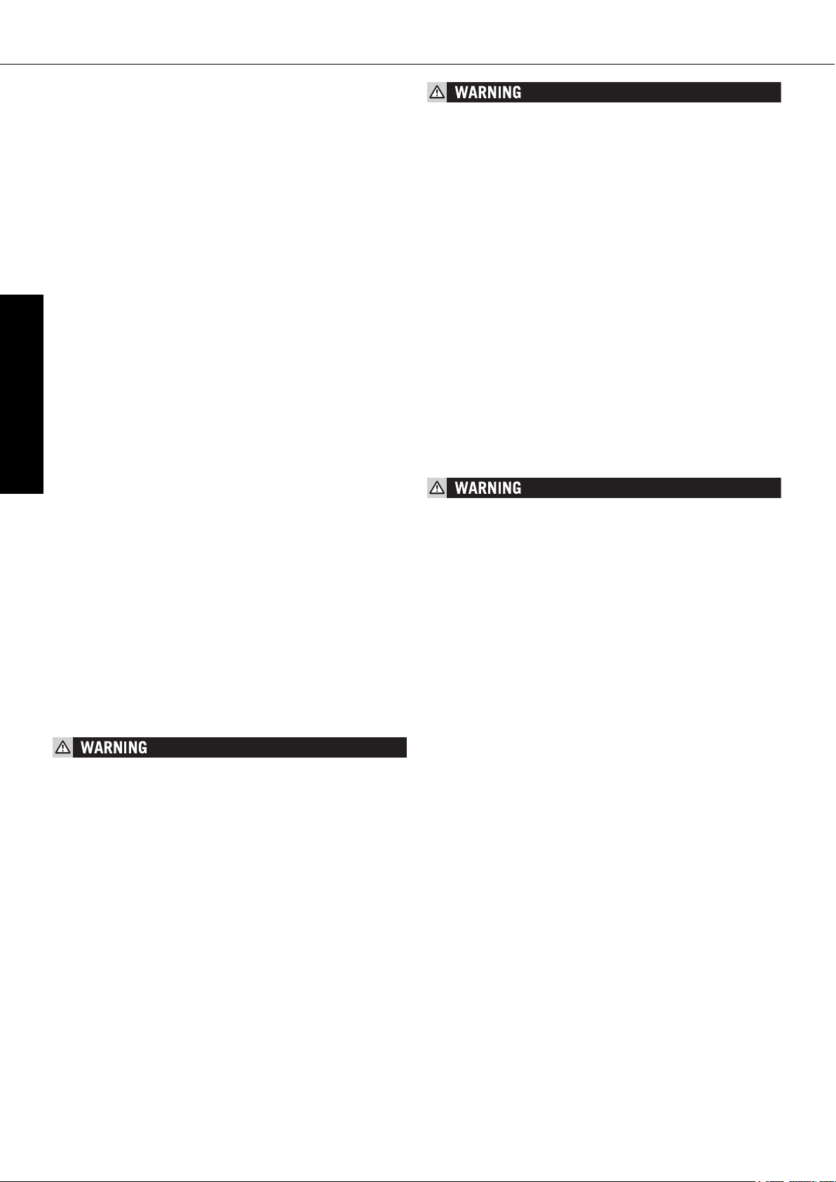
INFORMATION ABOUT THE SIDE STAND
Use your foot to push the side stand forward as far as possible, and lean your
motorcycle to the side. Make sure that your motorcycle is standing safely on
solid ground. Just in case, you can also put in a gear.
THE SIDE STAND IS DIMENSIONED FOR THE WEIGHT OF THE MOTORCYCLE ONLY.
IF YOU ARE SITTING ON THE MOTORBIKE AND THUS APPLY AN ADDITIONAL LOAD
ONTO THE SIDE STAND, YOU MAY CAUSE DAMAGE TO THE SIDE STAND OR THE
ENGINE CASE, AND YOUR MOTORBIKE MAY FALL OVER.
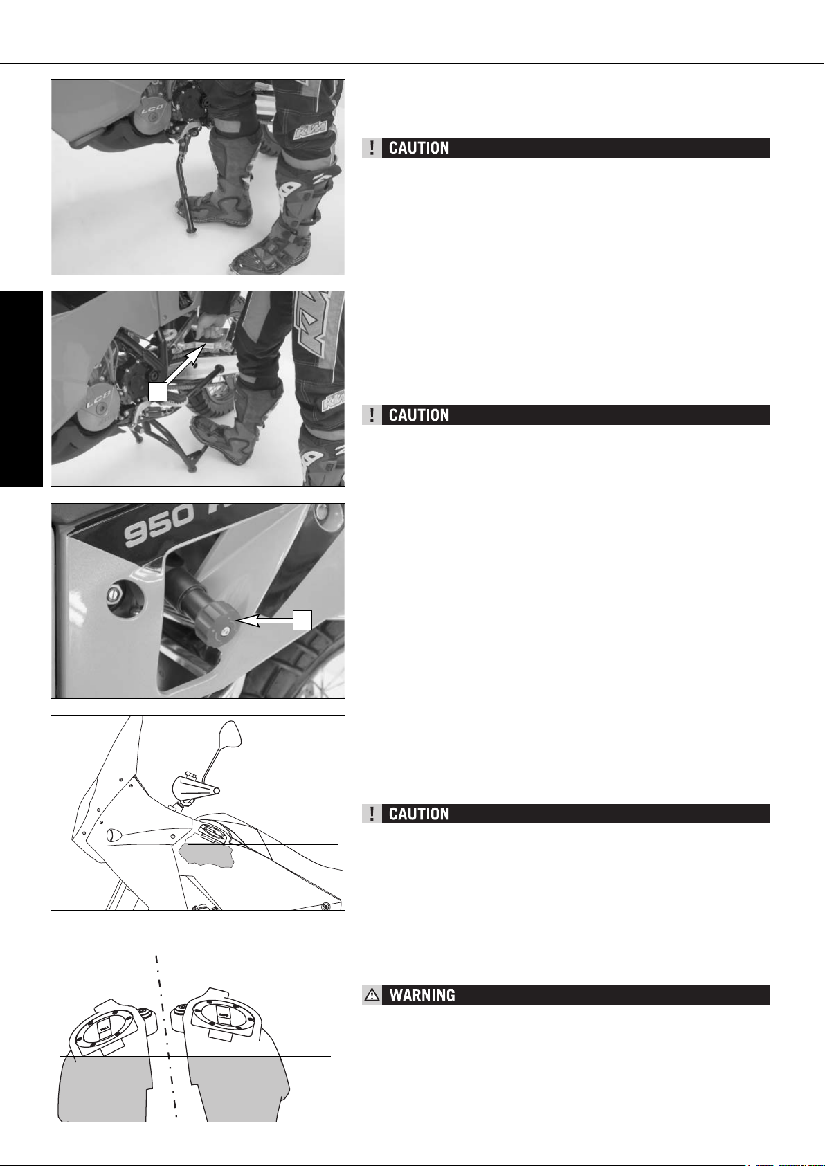
NOTE REGARDING THE CENTER STAND:
We advise the following procedure to place the motorcycle on the center stand
as effortlessly as possible:
a) press main stand to ground using foot
b) put your weight on the stand stabilizer and pull the motorcycle back by
the footrest support (see illustration).
Make sure that the ground is solid and that your motorcycle is standing
securely.
– THE CENTER STAND IS DESIGNED TO HOLD THE WEIGHT OF THE MOTORCY-
CLE ONLY. BY SITTING ON THE MOTORCYCLE, YOU WILL PUT ADDITIONAL WEIGHT
ON THE CENTER STAND, POSSIBLY CAUSING THE CENTER STAND OR FRAME
TO BE DAMAGED OR THE MOTORCYCLE TO FALL DOWN.
–
DO NOT PULL THE MOTORCYCLE BACK ON THE CENTER STAND BY HOLDING
THE HAND WHEEL [2] ON THE SHOCK ABSORBER ADJUSTMENT (IT COULD CAUSE
THE SHOCK ABSORBER TO LEAK) BUT USE THE FOOTREST BRACKET [1].
Fuel
In the condition at delivery, the LC8 engine requires unleaded fuel with at
least RON 95 (USA = Premium RON 91).
If using lower octane fuel, it is easy to change over to the pre-programmed
ignition curve for 80 - 94 octane (RON) (see activating the ignition curve for
low-octane fuel).
– USE UNLEADED FUEL WITH AT LEAST RON 95 (USA = PREMIUM RON 91). IF
USING LOWER OCTANE FUEL, THE IGNITION CURVE MUST BE CHANGED, OTH-
ERWISE ENGINE DAMAGE WILL OCCUR.
– THIS MOTORCYCLE IS EQUIPPED WITH 2 CATALYTIC CONVERTERS. LEADED
FUEL WILL DESTROY THE CATALYTIC CONVERTERS. PLEASE USE UNLEADED
FUEL ONLY.
The 950 Adventure has 2 tanks with 1 filler neck each. Fill the right tank
first, then the left tank (see drawing for the maximum filling level). If the right
tank is filled up to the filler neck, fuel may overflow when the motorcycle is
parked on the side stand after refueling when the fuel becomes warm.
GASOLINE IS HIGHLY FLAMMABLE AND POISONOUS. EXTREME CAUTION SHOULD
BE USED WHEN HANDLING GASOLINE. DO NOT REFUEL THE MOTORCYCLE NEAR
OPEN FLAMES OR BURNING CIGARETTES. ALWAYS SWITCH OFF THE ENGINE
BEFORE REFUELLING. BE CAREFUL NOT TO SPILL GASOLINE ON THE ENGINE OR
EXHAUST PIPE WHILE THE ENGINE IS HOT. WIPE UP SPILLS PROMPTLY. IF GASOLINE IS SWALLOWED OR SPLASHED IN THE EYES, SEEK A DOCTOR’S ADVICE
IMMEDIATELY.
MAX
MAX
2
1
Page 20

ENGLISH
19
Page 21

ENGLISH
20
PERIODIC MAINTENANCE SCHEDULE »
A CLEAN MOTORCYCLE CAN BE CHECKED MORE QUICKLY WHICH SAVES MONEY!
1st Service
after
1000 km
7500 km
or
once a year
15000 km
or
every 2 years
Engine
Change engine oil and oil filter
z z z
Clean oil screens of engine and oil tank
z z z
Clean magnetic drain plugs of engine and oil tank
z z z
Check oil lines for damage and kink-less arrangement
z z z
Renew spark plugs
z
Check and adjust valve clearance
z z
Check engine fastening bolts for tight fit
z z z
Check all engine bolts accessible from the outside for tight fit
z z z
Check clutch linings
z
Check clutch pressure booster system
z
Carburetor
Check carburetor connection boots for cracks and leaks
z z
Check synchronisation of carburators using special tool, if necessary adjust
z z
Check idle setting (1400 rpm)
z z
Check breeder hoses and fuel lines for damage and kink-free arrangement
z z
Add-on-parts
Check cooling system for leaks and antifreeze protection
z z z
Check radiator fan for proper operation
z z z
Check exhaust system for leaks and correct fitment
z z z
Check actuating cables for damage, smooth operation, and kink-less arrangement,adjust and lubricate
z z z
Check fluid level of the clutch master cylinder
z z
Check air filter, renew if necessary, clean air filter box
z
Check cables for damage and kink-less arrangement
z z z
Check headlamp adjustment
z z z
Check electrical system for function (low/high beams, stop light, turn indicators,headlamp,
z z z
flasher, tell-tale lamps, speedometer illumination, horn, side-stand switch, clutch switch,
emergency-off switch)
Make sure all bolts and nuts are tight
z z z
Brakes
Check brake fluid level, lining thickness, and brake discs
z z z
Change brake fluid
z
Check brake lines for damage and leaks
z z z
Check/adjust smooth operation, free travel of handbrake/footbrake levers
z z z
Check bolts of brake system for tight fit
z z z
Chassis
Check suspension strut and fork for leaks and proper operation
z z z
Clean fork dust sleeves
z z
Bleed fork legs
z z z
Check swinging-fork pivot
z z z
Check/adjust steering-head bearing
z z z
Check all chassis bolts for tight fit (fork plates, fork leg, axle nuts/bolts,
z z z
swinging-fork pivot, reversing lever, suspension strut)
Wheels
Check spoke tension and rim joint
z z z
Check tire condition and inflation pressure
z z z
Check chain, sprockets and chain guides for wear, force fit and tension
z z z
Check bolts on pinion and chain sprocket for locking devices and a tight fit
z z z
Lubricate chain
z z z
Check wheel bearings and jerk damper for play
z z
IF MOTORCYCLE IS USED FOR COMPETITION 7500 KM SERVICE SHOULD BE CARRIED OUT AFTER EVERY RACE!
SERVICE INTERVALLS SHOULD NEVER BE EXCEEDED BY MORE THAN 500 KM.
MAINTENANCE WORK DONE BY KTM AUTORIZED WORKSHOPS IS NOT A SUBSTITUTE OF CARE AND CHECKS DONE BY THE RIDER!
950
ADVENTURE
2005 US
Page 22

ENGLISH
21
PERIODIC MAINTENANCE SCHEDULE »
IMPORTANT RECOMENDED MAINTENANCE PROCEDURES TO BE PERFORMED BASED ON A SEPARATE SUPPLEMENT ORDER
at least
once a year
every 2 years
or 15000 km
Perform complete fork maintenance
z
Perform complete suspension strut maintenance
z
Clean and lubricate steering-head bearing and sealing elements
z
Clean and adjust the carburetors
z
Treat the electrical contacts and switches with contact spray
z
Treat battery connections with contact grease
z
Change coolant fluid
z
VITAL CHECKS AND CARE PROCEDURES TO CONDUCTED BY THE OWNER OR THE MECHANIC
before
each start
after
every cleaning
every 1000 km or
after off road use
Check oil level
z
Check brake fluid level
z
Check brake pads for wear
z
Check lighting system for proper operation
z
Check horn for proper operation
z
Lubricate and adjust actuating cables and nipples
z
Bleed fork legs in regular intervals
z
Clean chain
z
Lubricate chain
z z
Check chain tension
z
Check tire pressure and wear
z
Check coolant level
z
Check fuel lines for leaks
z
Check all control elements for smooth running
z
Check brake performance
z z
Treat exposed metal components (except for the braking and exhaust
z
systems) with wax-based anti-corrosion agents
Treat ignition/steering lock and light switch with contact spray
z
Page 23

ENGLISH
22
MAINTENANCE WORK ON CHASSIS AND ENGINE »
ALL SERVICING AND ADJUSTMENT PROCEDURES DESIGNATED BY AN ASTERISK * REQUIRE THE KNOWLEDGE AND SKILLS
OF A PROFESSIONAL. IN THE INTEREST OF YOUR OWN SAFETY, HAVE THESE PROCEDURES CARRIED OUT AT A AUTHORIZED
KTM WORKSHOP! AT A KTM WORKSHOP YOUR MOTORCYCLE WILL RECEIVE OPTIMAL SERVICING BY SPECIALLY TRAINED
MECHANICS.
– WHEN CLEANING THE MOTORCYCLE, DO NOT USE A HIGH PRESSURE CLEANING UNIT IF POSSIBLE, OTHERWISE WATER
WILL PENETRATE THE BEARINGS, CARBURETOR, ELECTRIC CONNECTORS ETC.
– DO NOT USE TOOTHED WASHERS OR SPRING WASHERS WITH THE ENGINE FASTENING SCREWS, AS THESE WORK INTO
THE FRAME PARTS AND KEEP WORKING LOOSE. INSTEAD, USE SELF-LOCKING NUTS.
– IF YOU UNSCREW ANY SCREWED CONNECTIONS WITH SELF-LOCKING NUTS, THEY MUST BE REPLACED WHEN MOUNT-
ING. IF NO SELF-LOCKING NUTS ARE AVAILABLE, APPLY LOCTITE 243 TO THE THREAD. THE SCREWS AND NUTS MUST BE
REPLACED IF THE THREAD IS DAMAGED.
– ALL SCREWS AND NUTS MUST BE TIGHTENED TO THE SPECIFIED TORQUE FIGURES USING A TORQUE WRENCH. IF SCREWS
OR NUTS ARE NOT ADEQUATELY TIGHTENED, THEY CAN BECOME LOOSE AND CAUSE THE MOTORCYCLE TO GO OUT OF
CONTROL WHILE YOU DRIVE. TIGHTENING THE SCREWS AND NUTS TOO TIGHTLY CAN DAMAGE THE THREAD AND
COMPONENTS.
– LET YOUR MOTORCYCLE COOL DOWN BEFORE BEGINNING ANY MAINTENANCE WORK IN ORDER TO AVOID GETTING BURNED.
– DISPOSE OF OIL, GREASE, FILTERS, FUELS, CLEANING AGENTS ETC. ACCORDING TO YOUR LOCAL REGULATIONS.
– UNDER NO CIRCUMSTANCES MAY USED OIL BE DISPOSED OF IN THE SEWAGE SYSTEM OR IN THE OPEN COUNTRYSIDE. 1
LITER USED OIL CONTAMINATES 1,000.000 LITERS WATER.
Removing and remounting the seat
Insert the ignition key in the seat lock and turn in a counterclockwise direction to unlock the seat. Lift the back of the seat and pull off towards the rear.
To remount, fit the nose [1] of the seat in the front, lower the back while pushing towards the front. Both noses [2] should fit into the frame. Insert the catch
bolts [3] in the lock housing and push the seat down in the back until you
hear the catch bolts snap into place.
Check whether the seat is correctly mounted.
IF NOT CORRECTLY MOUNTED, THE SEAT CAN SLIP WHILE YOU ARE DRIVING AND
CAUSE YOU TO LOSE CONTROL OF YOUR MOTORCYCLE.
Tool set
The tool set [4] and a recess [5] for several tool set wrenches are found under
the seat.
5
4
1
2
3
Page 24

ENGLISH
23
MAINTENANCE WORK ON CHASSIS AND ENGINE »
Adjusting the fork and shock absorber
There are a number of ways to adjust the fork and shock absorber to match
the chassis to your driving style and the payload.
We have provided a table with pragmatical values to help you tune up your
motorcycle. These tune-up specifications are reference values only and should
serve as a basis for your personal chassis and suspension tuning. Do not make
arbitrary changes to the settings (maximum ±40%) since this may impair the
handling characteristics (particularly in the high-speed range).
We recommend the "Driving Sport" damping adjustment for off-road rides on
soft subgrades (e.g. sand) and the "Driving Comfort" damping adjustment for
off-road rides on hard subgrades (e.g. rocks).
Adjusting compression damping of fork
Hydraulic compression damping determines the reaction when the fork is compressed. The degree of compression can be adjusted with adjusting
screws at the bottom of the fork legs.Remove the protecting cap [1].
Turn the adjusting screws [2] clockwise to increase damping, turn it counterclockwise to reduce damping during compression. Make the same damping
rate adjustments to both fork legs.
STANDARD ADJUSTMENT
– Turn adjusting screw clockwise as far as it will go.
– Turn 15 clicks in a counterclockwise direction.
Adjusting rebound damping of fork
Hydraulic rebound damping determines the reaction when the fork is
rebound. By turning the adjusting screw [3] (REB), the degree of damping of
the rebound can be adjusted. Turn the knob clockwise to increase damping,
turn it counterclockwise to reduce damping during rebounding. Make the same
damping rate adjustment to both fork legs.
STANDARD ADJUSTMENT
– Turn adjusting screw clockwise as far as it will go.
– Turn 18 clicks in a counterclockwise direction.
Adjusting the spring preload on the fork
The fork spring preload can be adjusted by turning the adjusting screws [4]
(wrench size 24 mm) ± 5 mm (0,2 in).
Turning in a clockwise direction will increase the preload, turning in a counterclockwise direction will decrease the preload. 1 turn will change the preload by 1 mm.
Changing the preload will not affect the rebound damping adjustment, although
adjusting screw [3] will turn at the same time.
Generally, if the preload is higher, the rebound damping should also be set
higher.
STANDARD ADJUSTMENT:
Turn the adjusting screw in a counterclockwise direction up to the stop and
then 5 turns in a clockwise direction.
BASIC SETTING
FORK
950 ADVENTURE
950 ADVENTURE S
Driving Comfort
Basic Setting
Driving Sport
Maximum Payload
Compression adjuster (clicks) 201510 10
Rebound adjuster (clicks) 231813 13
Spring preload (turns) 5
5
87
1
2
3
3
3
4
Page 25

ENGLISH
24
MAINTENANCE WORK ON CHASSIS AND ENGINE »
Compression damping of shock absorber
The shock absorber can synchronize the compression damping in the low and
high-speed range separately (Dual Compression Control).
Low and high speed refers to the movement of the shock absorber during compression and not to the speed of the motorcycle.
The low and high-speed technology overlaps.
The low-speed setting is primarily for slow to normal shock absorber compression rates.
The high-speed setting is effective at fast compression rates.
Turning in a clockwise direction will increase the damping, turning counterclockwise will decrease the damping.
STANDARD ADJUSTMENT LOW-SPEED:
– turn the adjusting screw [1] to the limit in a clockwise direction using a
screwdriver.
– unscrew the respective number of clicks for the specific type of shock absorber
in a counterclockwise direction.
950 Adventure . . . . . . . .20 clicks
950 Adventure S . . . . . . .20 clicks
STANDARD ADJUSTMENT HIGH-SPEED:
– Turn the adjusting screw in a clockwise direction up to the stop with a
socket wrench (wrench size 17 mm).
– Turn the adjusting screw in a counterclockwise direction the number of
turns specified for the respective type of shock absorber.
950 Adventure . . . . . . . .1.5 turns
950 Adventure S . . . . . .1.5 turns
THE DAMPING UNIT OF THE SHOCK ABSORBER IS FILLED WITH HIGH-COMPRESSION NITROGEN. NEVER TRY TO TAKE THE SHOCK ABSORBER APART OR TO DO
ANYMAINTENANCE WORK YOURSELF. SEVERE INJURIES COULD BE THE RESULT.
NEVER UNSCREW THE BLACK SCREW CONNECTION (24MM).
Rebound damping of shock absorber
By using the adjusting screw [4], the degree of damping of the rebound can
be adjusted. Turn the knob in a clockwise direction to increase damping, turn
it in a counterclockwise direction to reduce damping during rebounding.
STANDARD ADJUSTMENT:
– turn the adjusting screw clockwise to the stop.
– then turn the adjusting screw counterclockwise, counting the number of
clicks that corresponds to the respective type of shock absorber.
950 Adventure . . . . . . . .15 clicks
950 Adventure S . . . . . . .15 clicks
THE DAMPING UNIT OF THE SHOCK ABSORBER IS FILLED WITH HIGH-COMPRESSION NITROGEN. NEVER TRY TO TAKE THE SHOCK ABSORBER APART OR TO DO
ANY MAINTENANCE WORK YOURSELF. SEVERE INJURIES COULD BE THE RESULT.
NEVER UNSCREW THE BLACK SCREW CONNECTION [5] (15MM).
BASIC SETTING
SHOCK ABSORBER
950 ADVENTURE
Driving Comfort
Basic Setting
Driving Sport
Maximum Payload
Compression adjuster Low Speed (clicks) 252015 15
Compression adjuster High Speed (turns)
2
1.5
1 1
Rebound adjuster (clicks) 201510 10
Spring preload (turns) 6
6
10 18
BASIC SETTING
SHOCK ABSORBER
950 ADVENTURE S
Driving Comfort
Basic Setting
Driving Sport
Maximum Payload
Compression adjuster Low Speed (clicks) 252015 15
Compression adjuster High Speed (turns)
2
1.5
1 1
Rebound adjuster (clicks) 201510 10
Spring preload (turns) 6
6
10 12
1
4
5
Page 26

ENGLISH
25
MAINTENANCE WORK ON CHASSIS AND ENGINE »
Adjusting the preload of the shock absorber
The baggage and passenger put the main load on the shock absorber. To guarantee maximum handling performance, the preload of the shock absorber must
be adapted to the load.
The preload is hydraulically adjusted by turning the hand wheel [1]. Turning
in a clockwise direction will increase the preload, turning in a counterclockwise direction will reduce the preload.
Our pragmatical values are provided in the table "Basic settings for the shock
absorber" to help you to make the necessary adjustments.
STANDARD ADJUSTMENT:
– Turn the hand wheel in a counterclockwise direction up to the stop
– Turn the hand wheel 6 turns in a clockwise direction
Breathing the fork legs
Breath the fork legs regularly (see Maintenance Schedule).
To breath, place the motorcycle on the side stand and briefly remove the bleeder
screws [2] to allow any overpressure to escape from the fork.
EXCESSIVE PRESSURE IN THE INTERIOR OF THE FORK CAN CAUSE LEAKS IN THE
FORK. IF YOUR FORK IS LEAKING, IT IS RECOMMENDED TO OPEN THE BREATHER
PLUGS BEFORE HAVING THE SEALS REPLACED.
Cleaning the dust sleeves of the telescopic fork
The dust-protection bellows [3] are to remove dust and coarse dirt particles
from the fork tube. However, after some time, dirt may also get in behind the
dust-protection bellows. If this dirt is not removed, the oil sealing rings located
behind it may start to leak.
Use a screwdriver to lever the dust-protection bellows out of the outer tubes
and slide them downward.
Clean dust-protection bellows, outer tubes, and fork tubes thoroughly, and oil
them thoroughly with Universal oil spray (Motorex Joker 440) or engine oil.
Then, push dust-protection bellows into the outer tubes by hand.
NO OIL MAY REACH THE FRONT TIRE OR THE BRAKE DISKS SINCE THIS WOULD
CONSIDERABLY REDUCE THE TIRE'S ROAD GRIP AND THE BRAKING EFFECT OF
THE FRONT BRAKE.
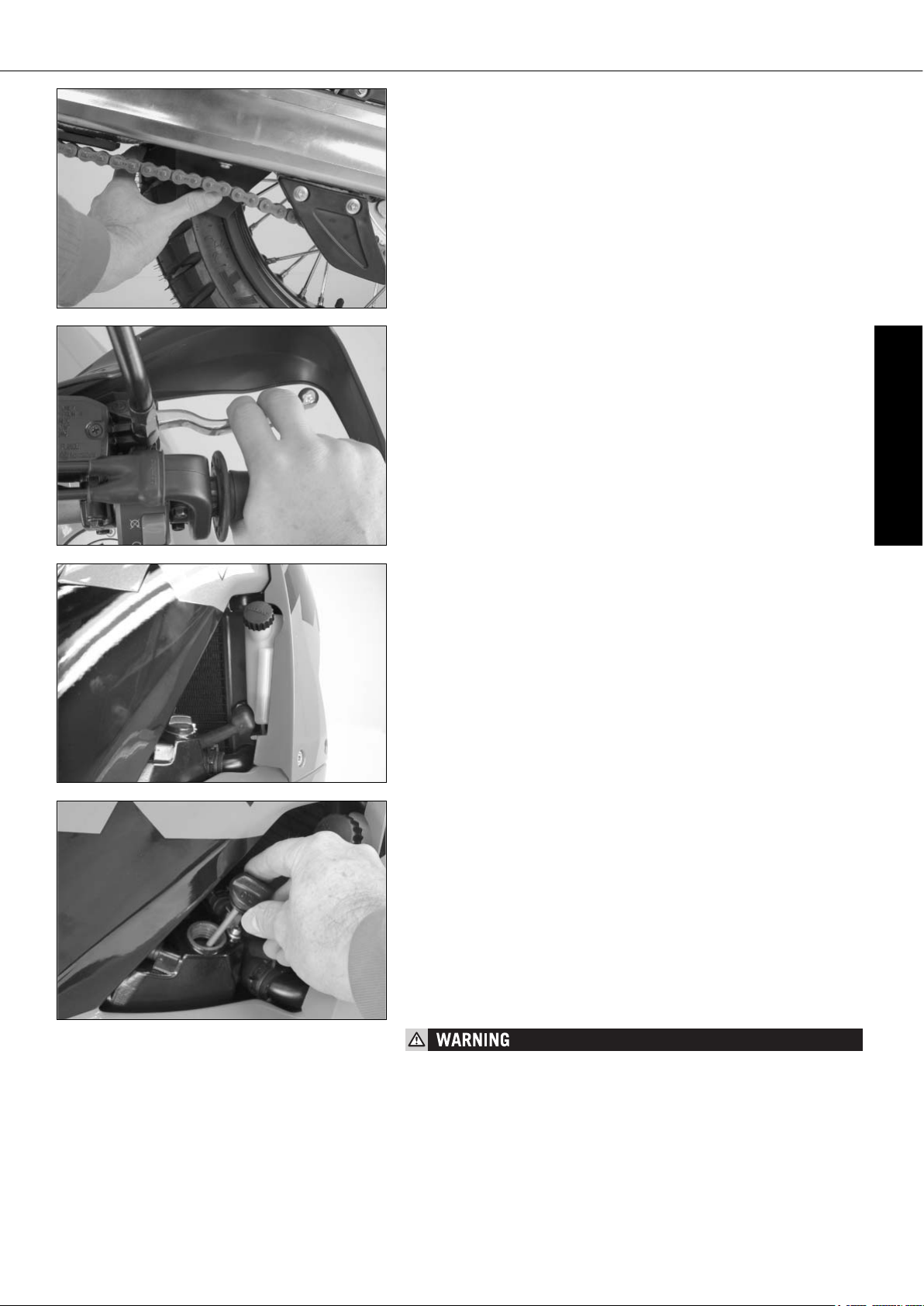
Checking the chain tension
Place the motorcycle on the side stand and switch the transmission to idle.
The chain should sag 35…40 mm (1.37 … 1.57 in) at the lower chainguard
screw [4].
– IF CHAIN TENSION IS TOO GREAT, PARTS WITHIN THE SECONDARY POWER
TRANSMISSION (CHAIN, CHAIN SPROCKETS, TRANSMISSION AND REAR WHEEL
BEARINGS) WILL BE SUBJECTED TO UNNECESSARY STRESS, RESULTING IN
PREMATURE WEAR AND EVEN CHAIN BREAKAGE.
– TOO MUCH SLACK IN THE CHAIN, ON THE OTHER HAND, CAN RESULT IN THE
CHAIN JUMPING OFF THE CHAIN WHEELS. IF THIS HAPPENS, THE CHAIN COULD
ALSO BLOCK THE REAR WHEEL OR DAMAGE THE ENGINE.
– IN EITHER CASE THE OPERATOR IS LIKELY TO LOSE CONTROL OF THE MOTOR-
CYCLE.
35 … 40 mm
1
2
3
4
Page 27

ENGLISH
26
MAINTENANCE WORK ON CHASSIS AND ENGINE »
Correct chain tension
Loosen collar nut [1], loosen counter nuts [2], and turn right and left
adjusting screws [3] equally far. Tighten counter nuts [2].
Before tightening the wheel spindle, verify that the chain adjusters [4] are
sitting close to the adjusting screws and that the rear wheel has been
aligned with the front wheel.
Tighten collar nut [1] with 90 Nm.
IF YOU DON’T HAPPEN TO HAVE A TORQUE WRENCH AT HAND, MAKE SURE YOU
HAVE THE TIGHTENING TORQUE CORRECTED BY A KTM DEALER AS SOON AS POSSIBLE. A LOOSE AXLE MAY LEAD TO AN UNSTABLE DRIVING BEHAVIOR OF YOUR
MOTORCYCLE.
Chain maintenance
The maintenance of the X-ring chain is reduced to a minimum. Clean with a
soft water jet. Never use a brush or solvent to clean the chain. When the chain
is dry use a chain spray specially made for X-ring chains (Motorex Chainlube
622).
– NO LUBRICATION IS ALLOWED TO REACH THE REAR TIRE OR THE BRAKE DISK,
EITHERWISE THE ROAD ADHERENCE AND THE REAR WHEEL BRAKING EFFECTS
WOULD BE STRONGLY REDUCED AND THE MOTORCYCLE COULD EASILY GET
OUT OF CONTROL.
– THE CHAIN DOES NOT HAVE A CHAIN JOINT FOR SAFETY REASONS. ALWAYS
HAVE THE CHAIN REPLACED IN AN AUTHORIZED KTM WORKSHOP WHERE THE
SERVICE TECHNICANS HAVE THE REQUIRED RIVETING TOOL.
– NEVER MOUNT A NORMAL CHAIN JOINT.
Also check sprockets and chain guides for wear, and replace if necessary.
Checking the chain for wear
To check the chain for wear proceed as follows:
Switch the transmission to idle and put a load of approx. 15 kilograms
(33 lbs) on the lower part of the chain (see illustration). Now measure the
distance between 18 chain rollers on the upper part of the chain. The chain
needs to be replaced when the distance is 272 mm (10.70 in). Since chains
do not always wear evenly, repeat the measurement at different parts of the
chain.
Replace the chain if any X-rings are missing.
NOTE:
If you mount a new chain, the sprockets should also be replaced. New chains
wear faster if used on old used sprockets.
15 KG
max. 272 mm
1 2 3
16 17 18
1
3
4
2
4
Page 28

ENGLISH
27
MAINTENANCE WORK ON CHASSIS AND ENGINE »
General informations about KTM disc brakes
BRAKE CALIPERS:
The brake calipers of this series “float“. This means that the brake calipers
are not solidly attached to the caliper support. Thus, the brake pads are always
in optimum contact with the brake disc. Secure the screws of the caliper support with Loctite 243 and tighten to 25 Nm.
FOR SAFETY REASONS, ALWAYS HAVE MAINTENANCE WORK AND REPAIRS TO THE
BRAKE SYSTEM PERFORMED BY AN AUTHORIZED KTM WORKSHOP.
BRAKE PADS:
Your motorcycle is equipped with sintered brake pads in the front and rear
and homologated accordingly. They guarantee maximum braking
performance.
Front brake pads: Toshiba TT 2172 HH
Rear brake pads: Toshiba TT 2701 HH
BRAKE PADS AVAILABLE IN THE ACCESSORY TRADE ARE OFTEN NOT AUTHORIZED FOR OPERATION OF YOUR KTM MOTORCYCLE IN ROAD TRAFFIC. THE BRAKE
PADS DESIGN AND FRICTION FACTOR AND THEREFORE THE BRAKING POWER CAN
DEVIATE SIGNIFICANTLY FROM ORIGINAL KTM BRAKE PADS. IF YOU USE DIFFERENT BRAKE PADS THAN THOSE PROVIDED WITH THE ORIGINAL EQUIPMENT, IT
CANNOT BE WARRANTED THAT THEY ARE AUTHORIZED FOR USE IN ROAD TRAFFIC. YOUR MOTORCYCLE WILL NOT LONGER COMPLY WITH THE REGULATIONS
AUTHORIZING THE USE OF VEHICLES FOR ROAD TRAFFIC AND THE WARRANTY
WILL BE VOID.
BRAKE FLUID RESERVOIRS:
The brake fluid reservoirs on the front and rear wheel brakes have been
designed in such a way that even if the brake pads are worn it is not necessary to top up the brake fluid. There is no reason to remove the reservoir cap
under normal conditions. If the brake fluid level drops below the minimum
either the brake system has a leak or the brake pads are completely worn down.
In this case, consult an authorized KTM dealer immediately.
BRAKE FLUID:
KTM fills the brake systems with Motorex Brake Fluid DOT 5.1 brake fluid,
one of the best brake fluids that is currently available. We recommend that
you continue to use it. DOT 5.1 brake fluid is based on glycol ether and of an
amber color. If you do not have any DOT 5.1 for refilling, you may use DOT
4 brake fluid. However, you should replace it as soon as possible
by DOT 5.1.
Never use DOT 5 braking fluid. It is based on silicone oil and has a purple
color. Gaskets and brake hoses are not compatible with it.
Brake fluid is exposed to a high thermal load and absorbs moisture from the
air, which lowers the boiling point. The brake fluid should therefore be changed
at the prescribed intervals.
HAVE THE BRAKE FLUID FOR THE FRONT AND REAR BRAKE CHANGED AT AN
AUTHORIZED KTM WORKSHOP EVERY 2 YEARS.
BRAKE DISCS:
Wear reduces the thickness of the brake disc in the area of contact [1] with
the brake pads. The brake disk should not be thinner than 4.5 mm (0.18 in)
at the weakest point [A]. Check the wear at several points.
BRAKE DISKS THAT ARE LESS THAN 4.5 MM (0.18 IN) THICK ARE A SAFETY HAZARD. HAVE WORN BRAKE DISKS REPLACED IMMEDIATELY.
1
A
Page 29

ENGLISH
28
MAINTENANCE WORK ON CHASSIS AND ENGINE »
Adjusting of free travel at the hand brake lever
Free travel at the hand brake lever may be readjusted by using adjusting
screw [1]. In this way, the position of the point of pressure (i.e., the resistance you feel on the hand brake lever when the brake pads are pressed against
the brake disc) can be adjusted for any hand size.
AT THE HAND BRAKE LEVER, FREE TRAVEL MUST AT LEAST BE 3 MM (0.12 IN).
ONLY THEN MAY THE PISTON IN THE HAND BRAKE CYLINDER BE MOVED (TO BE
RECOGNIZED BY THE GREATER RESISTANCE OF THE HAND BRAKE LEVER). IF
THIS FREE TRAVEL IS NOT PROVIDED, PRESSURE WILL BUILD UP IN THE BRAKING SYSTEM, AND THE FRONT WHEEL BRAKE MAY FAIL DUE TO OVERHEATING.
Checking of brake fluid level - front brake
The brake fluid reservoir is linked with the hand brake cylinder at the
handlebar and the reservoir is provided with an inspection glass. With the reservoir in a horizontal position, the brake fluid level should not go below middle
of the glass.
– IF THE BRAKE FLUID LEVEL DROPS BELOW THE MINIMUM EITHER THE BRAKE
SYSTEM HAS A LEAK OR THE BRAKE PADS ARE COMPLETELY WORN DOWN.
IN THIS CASE, CONSULT AN AUTHORIZED KTM DEALER IMMEDIATELY.
– HAVE THE BRAKE FLUID CHANGED AT AN AUTHORIZED KTM WORKSHOP
EVERY 2 YEARS.
Refilling the front brake fluid reservoir *
It is not necessary to refill brake fluid under normal conditions (see General
information on KTM disk brakes).
However, the brake fluid must be refilled as soon as the brake fluid level reaches
the MIN mark.
Remove the screws [2] and the cover [3] with the rubber boot [4]. Push the
front brake caliper pistons all the way back, demounting the front wheel if
necessary. Move the hand brake cylinder in a horizontal position and fill DOT
5.1 brake fluid (Motorex Brake Fluid DOT 5.1) up to 5 mm (0.2 in) under the
top edge of the reservoir. Remount the rubber boot, cover and screws. Wash
off any overflowing or spilled brake fluid with water. Actuate the front brake
until you feel the point of pressure.
– ACTUATE THE FRONT BRAKE UNTIL YOU FEEL THE POINT OF PRESSURE.
– NEVER USE DOT5 BRAKE FLUID! IT IS BASED ON SILICONE OIL AND OF A PUR-
PLE COLOR. SEALS AND BRAKE HOSES MUST BE ESPECIALLY ADAPTED
TO IT.
– STORE BRAKE FLUID OUT OF REACH OF CHILDREN.
– BRAKE FLUID CAN CAUSE SKIN IRRITATION. AVOID CONTACT WITH SKIN AND
EYES. IF YOU GET BRAKE FLUID IN YOUR EYES, RINSE WITH PLENTY OF WATER
AND CONSULT A DOCTOR.
– DON’T LET BRAKE FLUID GET IN CONTACT WITH PAINT, IT IS AN EFFECTIVE
PAINT REMOVER.
– USE ONLY CLEAN BRAKE FLUID TAKEN FROM A TIGHTLY SEALED CONTAINER.
Checking the front brake pads
The brake pads can be inspected from below. The linings must be at least
1 mm (0.04 in) thick.
At their most worn point brake pad linings should not be thinner than
1 mm, otherwise they could lead to brake failure. For your own safety don’t
put off having your brake pads changed.
IF THE BRAKE PADS ARE REPLACED TOO LATE WHEN THE LINING IS PARTLY OR
COMPLETELY WORN OFF, THE STEEL PARTS ON THE BRAKE PADS WILL GRIND
AGAINST THE BRAKE DISKS. THIS SIGNIFICANTLY DECREASES THE BRAKING
EFFECT AND DESTROYS THE BRAKE DISKS.
min.
1 mm
2
3
4
5 mm
min. 3 mm
1
Page 30

ENGLISH
29
MAINTENANCE WORK ON CHASSIS AND ENGINE »
Changing the basic position of the foot brake lever *
Loosen the counter nut [1] and turn the push rod [2] until the foot brake lever
reaches the right position. Tighten the counter nut.
Checking rear brake fluid level
The brake fluid reservoir for the rear disk brake is combined with the foot
brake cylinder and has an inspection window. The brake fluid level should not
drop below the "MIN" mark when the motorcycle is in a vertical position.
– IF THE BRAKE FLUID LEVEL DROPS BELOW THE MINIMUM EITHER THE BRAKE
SYSTEM HAS A LEAK OR THE BRAKE PADS ARE COMPLETELY WORN DOWN.
IN THIS CASE, CONSULT AN AUTHORIZED KTM DEALER IMMEDIATELY.
– HAVE THE BRAKE FLUID CHANGED AT AN AUTHORIZED KTM WORKSHOP
EVERY 2 YEARS.
Refilling the rear brake fluid reservoir *
It is not necessary to refill brake fluid under normal conditions (see General
information on KTM disk brakes).
However, the brake fluid must be refilled as soon as the brake fluid level reaches
the MIN mark.
Remove the screws [3] and the cover [4] with the rubber boot [5]. Push the
rear brake caliper pistons all the way back, demounting the rear wheel if necessary. Fill DOT 5.1 brake fluid (Motorex Brake Fluid DOT 5.1) up to
12 mm (0.5 in) under the top edge of the reservoir. Remount the rubber boot,
cover and screws. Wash off any overflowing or spilled brake fluid with water.
Actuate the rear brake until you feel the point of pressure.
– ACTUATE THE REAR BRAKE UNTIL YOU FEEL THE POINT OF PRESSURE.
– NEVER USE DOT5 BRAKE FLUID! IT IS BASED ON SILICONE OIL AND OF A PUR-
PLE COLOR. SEALS AND BRAKE HOSES MUST BE ESPECIALLY ADAPTED
TO IT.
– STORE BRAKE FLUID OUT OF REACH OF CHILDREN.
– BRAKE FLUID CAN CAUSE SKIN IRRITATION. AVOID CONTACT WITH SKIN AND
EYES. IF YOU GET BRAKE FLUID IN YOUR EYES, RINSE WITH PLENTY OF WATER
AND CONSULT A DOCTOR
– DON’T LET BRAKE FLUID GET IN CONTACT WITH PAINT, IT IS AN EFFECTIVE
PAINT REMOVER.
– USE ONLY CLEAN BRAKE FLUID TAKEN FROM A TIGHTLY SEALED CONTAINER.
Checking the rear brake pads
The brake pads can be inspected from the rear. The thickness of the linings
may not be less than 1 mm (0.04 in).
AT THEIR MOST WORN POINT BRAKE PAD LININGS SHOULD NOT BE THINNER
THAN 1 MM, OTHERWISE THEY COULD LEAD TO BRAKE FAILURE. FOR YOUR OWN
SAFETY DON’T PUT OFF HAVING YOUR BRAKE PADS CHANGED.
IF THE BRAKE PADS ARE REPLACED TOO LATE SO THAT THE LINING IS PARTLY
OR ENTIRELY WORN AWAY, THE STEEL COMPONENTS OF THE BRAKE PAD WILL
RUB AGAINST THE BRAKE DISC, IMPARING THE BRAKING EFFECT AND DESTROYING THE BRAKE DISC.
12 mm
min.
1 mm
1
2
3
4
5
Page 31

ENGLISH
30
MAINTENANCE WORK ON CHASSIS AND ENGINE »
Dismounting and mounting the front wheel *
Jack the motorcycle up at the underride protection until the front wheel no
longer touches the ground.
Loosen the collar screw [1] and the clamp screws [2] at both fork leg axle
passages. Unscrew the collar screw approx. 8 turns, pressing your hand against
the collar screw to push the axle passage out of the fork leg and remove the
collar screw. Hold the front wheel and pull out the axle passage. Slightly pull
one brake caliper out and take the front wheel off the fork.
Take the left [3] and right distance bushing out of the shaft seal rings.
– DO NOT OPERATE THE HAND BRAKE WHEN THE FRONT WHEEL HAS BEEN
DISMOUNTED.
– BE CAREFUL NOT TO DAMAGE THE BRAKE DISKS WHEN YOU LAY THE FRONT
WHEEL DOWN.
Before remounting the front wheel, clean and grease the shaft seal rings [4]
and the bearing surface [A] of the distance bushings and mount the distance
bushings (wide distance bushing in the left shaft seal ring). Slightly push back
the brake pads with a screwdriver. Position the front wheel against the brake
disks according to the direction of travel (see arrow [B]).
To mount the front wheel, lift the wheel into the fork, slightly pull one brake
caliper out and push the tire in between the brake calipers. Insert the brake
disks in the brake calipers and mount the axle passage.
Mount the collar screw [1] and tighten slightly. Tighten the clamp screws [2]
on the right fork leg axle passage (in the direction of travel) tighten to prevent the axle passage from turning and tighten the collar nut to 60 Nm.
Loosen the clamp screws on the right fork leg axle passage, take the motorcycle off the stand, actuate the front wheel brake and vigorously compress
the fork several times to align the fork legs.
Now you can tighten the clamp screws on both fork leg axle passages to
15 Nm.
– IF YOU DO NOT HAVE A TORQUE WRENCH TO MOUNT THE WHEEL, HAVE THE
TORQUES CORRECTED BY AN AUTHORIZED KTM WORKSHOP AS SOON AS POS-
SIBLE. A LOOSE AXLE PASSAGE CAN CAUSE THE MOTORCYCLE'S HANDLING
PERFORMANCE TO BECOME INSTABLE.
– AFTER MOUNTING THE FRONT WHEEL, KEEP OPERATING THE HAND BRAKE
UNTIL THE PRESSURE POINT RETURNS.
– ALWAYS KEEP THE BRAKE DISKS FREE FROM OIL AND GREASE, OTHERWISE
THE BRAKING EFFECT WILL BE SIGNIFICANTLY REDUCED.
2
1
2
4
3
A
B
Page 32

ENGLISH
31
MAINTENANCE WORK ON CHASSIS AND ENGINE »
Dismounting and mounting the rear wheel *
Set the motorcycle on the center stand to keep the rear wheel from touching
the ground.
Unscrew the collar nut [1], remove the chain tensioner [2], hold on to the
rear wheel while you pull out the axle passage [3]. Push the rear wheel as far
to the front as possible, take the chain off of the rear sprocket and lay it on
the rear sprocket guard. Carefully lift the rear wheel out of the swing arm.
– DO NOT OPERATE THE REAR BRAKE WHEN THE REAR WHEEL HAS BEEN DIS-
MOUNTED.
– ALWAYS PLACE THE WHEEL ON THE GROUND WITH THE BRAKE DISC POINT-
ING UPWARDS. OTHERWISE THE BRAKE DISC MAY BE DAMAGED.
– IF THE AXLE IS DISMOUNTED, CLEAN THE THREAD OF THE WHEEL SPINDLE
AND COLLAR NUT THOROUGHLY AND APPLY A NEW COAT OF GREASE (MOTOREX
LONG THERM 2000) TO PREVENT THE THREAD FROM JAMMING.
NOTE: Check the damping rubbers in the rear wheel hub when the rear wheel
is dismounted.
Before remounting the rear wheel, clean and grease the bearing surface of
the bushings [4] and the shaft seal ring [5].
The rear wheel is remounted in reverse order. Pay attention to the same
mounting position of the axle passage and the chain tensioner and make sure
the noses [A] point to the front.
Before tightening the collar nut to 90 Nm, push the rear wheel forwards so
that the chain tensioners lie on the tension screws.
– IF YOU DON’T HAPPEN TO HAVE A TORQUE WRENCH AT HAND, MAKE SURE
YOU HAVE THE TIGHTENING TORQUE CORRECTED BY A KTM DEALER AS SOON
AS POSSIBLE. A LOOSE WHEEL SPINDLE MAY LEAD TO AN UNSTABLE DRIV-
ING BEHAVIOR OF YOUR MOTORCYCLE.
– AFTER MOUNTING THE REAR WHEEL, KEEP OPERATING THE FOOTBRAKE
UNTIL THE PRESSURE POINT RETURNS.
– IT IS VERY IMPORTANT TO KEEP THE BRAKE DISK FREE FROM OIL AND
GREASE, OTHERWISE THE BRAKING EFFECT WOULD BE STRONGLY REDUCED.
Checking the shock absorption rubbers in the rear hub *
Adventure models have a damped rear wheel hub. For this purpose, the engine
power is conveyed from the rear sprocket via 6 shock absorption rubbers [6]
to the rear wheel. These 6 absorption rubbers wear with increasing operation
time, and should be checked for wear whenever the rear wheel is dismounted.
For this purpose, lie the rear wheel on a work bench with the rear sprocket
upwards, and put the wheel spindle in the hub. Now hold the rear wheel firmly
and try to turn the rear sprocket. The rear sprocket may not turn more than
maximum 5 mm (0,2 in) measured on the outside. If the play in the chain
wheel is larger, all 6 shock absorption rubbers are to be replaced.
Check the shock absorption rubbers for signs of damage and dirt.
IF THE SHOCK ABSORPTION RUBBERS ARE NOT REPLACED IN GOOD TIME, THE
REAR SPROCKET CARRIER AND THE REAR HUB WILL BE DAMAGED. ALLWAYS
REPLACE ALL 6 ABSORPTION RUBBERS, NEVER SINGLE RUBBERS.
max. 5 mm
6
4
5
3
A
1
2
A
Page 33

ENGLISH
32
MAINTENANCE WORK ON CHASSIS AND ENGINE »
Tires, air pressure
Tire type, tire condition, and how much air pressure the tires have in them
affect the way your motorcycle rides, and they must therefore be checked whenever you’re getting ready to go anywhere on your motorcycle.
– IN ORDER TO ENSURE RIDING SAFETY AND OPTIMAL RIDING PERFORMANCE,
ONLY KTM-APPROVED TIRES MAY BE USED. OTHER TIRES CAN HAVE A NEG-
ATIVE EFFECT ON RIDING PERFORMANCE (E.G. VIBRATION AT HIGHER SPEEDS).
– DO NOT EXCEED THE RESPECTIVE MAXIMUM SPEED FOR TIRES DESIGNED
WITH A SPEED INDEX OF LESS THAN "V“ (240 KPH, 150 MILES/H). A STICKER
SHOWING THE MAXIMUM SPEED MUST BE AFFIXED TO THE MOTORCYCLE
WITHIN THE DRIVER'S FIELD OF VISION.
– Tire type and size can be found in the technical specifications and in the
homologation certificate
– Tire condition has to be checked every time you want to ride your motor-
cycle. Before leaving check for punctures and nails or other sharp objects
that might have become embedded in the tire.
– Refer to the specific regulations in your country for minimum tire tread
requirements. We recommend replacing tires at the latest when the tread
is down to 2 mm (0.08 in).
– Tire pressure should be checked regularly on a “cold” tire. Adapt the air
pressure to the motorcycle's total weight. Proper pressure ensures opti-
mum driving comfort and extends the life of your tires.
– DO NOT MOUNT TIRES WHICH HAVE NOT BEEN APPROVED BY KTM. OTHER
TIRES COULD HAVE ADVERSE EFFECTS ON THE WAY YOUR MOTORCYCLE
RIDES.
– USE TIRES OF THE SAME BRAND AND TYPE FOR THE FRONT AND REAR
WHEELS.
– FOR YOUR OWN SAFETY REPLACE DAMAGED TIRES IMMEDIATELY.
– WORN TIRES CAN HAVE A NEGATIVE EFFECT ON HOW YOUR MOTORCYCLE
PERFORMS, ESPECIALLY ON WET SURFACES
– IF AIR PRESSURE IS TOO LOW, ABNORMAL WEAR AND OVERHEATING OF THE
TIRE CAN RESULT
– NEW WHEELS HAVE A SMOOTH SURFACE, WHICH MEANS THAT THEY MUST
BE RUN IN TO ACHIEVE FULL GRIP. FOR THIS PURPOSE, RIDE THE MOTOR-
CYCLE CAREFULLY AT MODERATE SPEED DURING THE FIRST 200 KILOMETERS
(125 MILES) WITH NEW TIRES, TILTING THE VEHICLE AT DIFFERENT ANGLES
SO THAT ALL SECTIONS ARE PROPERLY ROUGHENED. TIRES WILL NOT DIS-
PLAY
THEIR FULL GRIP CHARACTERISTICS UNTIL THEY ARE PROPERLY RUN IN.
– FOR REASONS OF SAFETY, IT IS RECOMMENDED TO EXCHANGE THE VALVE
INSERT WHENEVER A NEW TIRE IS MOUNTED.
Checking spoke tension
The correct spoke tension is very important for the stability of the wheels and
thus for riding safety. A loose spoke causes the wheel to become unbalanced
and before long other spokes will have come loose. Check spoke tension, especially on a new motorcycle, in regular intervals. For checking, tap on each
spoke with the blade of a screw driver (see illustration). A clear tone must be
the result. Dull tones indicate loose spokes. If necessary, have the spokes retightened and the wheel centered by a KTM dealer.
– IF YOU CONTINUE TO DRIVE WITH LOOSE SPOKES, THE SPOKES CAN TEAR
AND LEAD TO AN INSTABLE HANDLING PERFORMANCE. TORN SPOKES CAN
DAMAGE THE AIR HOSE. THE LOSS OF AIR CAN EASILY CAUSE THE MOTOR-
CYCLE TO GO OUT OF CONTROL.
– EXCESSIVELY TENSIONED SPOKES MAY RUPTURE DUE TO LOCAL OVERLOAD-
ING. THE SPOKES MUST BE TENSIONED TO 5 NM ± 1 NM.
Battery
The battery is located in the underride protection in front of the engine and
is maintenance-free. It is not necessary to check the electrolyte level or to
refill water. Simply keep the battery poles clean and slightly grease them with
an acid-free grease if necessary.
NEVER REMOVE THE CLOSING COVER [1] OTHERWISE THE BATTERY WILL BE
DAMAGED.
1
TIRES – AIR PRESSURE
950 Adventure front rear
Road, driver only 2.4 bar (34psi) 2.6 bar (37psi)
Road, with passenger
2.4 bar (34psi) 2.8 bar (40psi)
maximum payload 2.4 bar (34psi) 2.8 bar (40psi)
Page 34

ENGLISH
33
MAINTENANCE WORK ON CHASSIS AND ENGINE »
Demounting and mounting the battery *
The battery does not need to be demounted unless the motorcycle is being
immobilized.
To demount the battery, remove the screws [1] and fold the underride protection [2] down. Remove the screws [3] and tilt the battery cover [4] to the front.
First disconnect the negative pole and then the positive pole. Remove the battery cover and remove the battery together with the battery case.
Recharge the battery before and after storage. Storage temperature:
0 - 35°C (32 - 95°F).
To mount, place the battery and battery case in the battery compartment and
mount the battery cover. First connect the positive pole, then the negative
pole to the battery to avoid a short circuit. Fold the battery cover up and fasten with 2 screws. Fold the underride protection up, apply Loctite 243 (screw
retainer) to both screws, mount the screws and tighten to 25 Nm (19 ft.lbs).
– IF ELECTROLYTE (SULPHURIC ACID) LEAKS FROM THE BATTERY, PROCEED WITH
GREAT CARE. THE ELECTROLYTE CAN CAUSE SEVERE BURNS.
– IN THE CASE OF SKIN CONTACT RINSE THOROUGHLY WITH WATER.
– IN THE CASE OF CONTACT WITH THE EYES, THOROUGHLY RINSE EYES WITH
WATER FOR AT LEAST 15 MINUTES. IMMEDIATELY CONSULT A DOCTOR.
– THE BATTERY IS A CLOSED MODEL BUT CAN NEVERTHELESS EMIT EXPLO-
SIVE GASES. AVOID SPARKS AND OPEN FIRE NEAR THE BATTERY.
– DEFECTIVE BATTERIES MUST BE STORED OUT OF THE REACH OF CHILDREN.
ENSURE PROPER DISPOSAL OF DISCARDED BATTERIES.
– THE SCREWS ON THE UNDERRIDE PROTECTION MUST BE SECURED WITH LOC-
TITE 243 TO PREVENT THEM FROM BECOMING LOOSE.
NEVER DISCONNECT THE BATTERY WHILE THE ENGINE IS RUNNING. THIS WILL
DESTROY THE RECTIFIER-REGULATOR.
Charging the battery
NOTE: a battery charger, item no. 58429074000, is available from your KTM
dealer. You can also use the battery charger to test the off load voltage, startability of the battery and the generator capacity.
Fold the underride protection and the battery cover down and check the batter's charging condition. Use a voltmeter to measure the voltage between the
battery poles (off-load voltage).
Accurate results can only be obtained if the battery has neither been charged
nor discharged during a period of 30 minutes preceding the measuring.
Recharging is not required if the voltage exceeds 12.4 V.
Recharge if the voltage is below 12.4 V.
CHARGING:
Connect the battery charger to the cables [5] leading to the battery cover.
These cables were mounted since the battery poles are hard to reach and short
circuits easily occur when handled.
Charge the battery for 5 to a max. of 10 hours with 1,4 amperes and a max.
of 14.4 volts.
For a quick charge, do not charge the battery longer than 1 hour with 4.5
amperes and a max. of 14.4 volts.
– IF THE CHARGE CONDITION CANNOT BE ESTABLISHED, THE BATTERY MAY ONLY BE
CHARGED 5 TO A MAX. OF 10 HOURS WITH 1.4 AMPERES AND A MAX. OF 14.4 VOLTS.
– ALWAYS CONNECT THE BATTERY TO THE CHARGING UNIT BEFORE TURNING THE
CHARGING UNIT ON.
– WHEN RECHARGING THE BATTERY IN CLOSED ROOMS THERE IS SUFFICIENT
VENTILATION. EXPLOSIVE GASES ARE RELEASED DURING THE BATTERY CHARGING
PROCESS.
– CHARGING TIME AND CHARGING VOLTAGE SHOULD NOT EXCEED THE STATED VAL-
UES. OTHERWISE ELECTROLYTE WILL BE RELEASED THROUGH THE SAFETY VALVES.
– AVOID QUICK CHARGING IF POSSIBLE.
– TO AVOID DAMAGE, DO NOT REMOVE THE LOCKING BAR.
Connecting the battery jumper cable
Fold the underride protection and the battery cover down (see demounting
and mounting the battery). Connect the battery jumper cable to the cables
leading to the battery-cover. Connect the positive battery cable first.
– DO NOT ALLOW THE BARE PARTS OF THE JUMPER CABLE TO COME INTO CON-
TACT WITH EACH OTHER. A SHORT CIRCUIT CAN DAMAGE THE ELECTRIC SYS-
TEM OF BOTH VEHICLES.
– ONLY CONNECT THE BATTERIES BRIEFLY TO AVOID OVERLOADING.
VOLT
1
1
2
3
3
4
Page 35

ENGLISH
34
MAINTENANCE WORK ON CHASSIS AND ENGINE »
Main fuse
The main fuse protects all of the motorcycle's current consumers. The main
fuse is located in the starter relay under the right engine cowl. Remove the
screws [1] and take off the engine cowl [2].
DO NOT BURN YOURSELF ON THE HOT EXHAUST PIPE.
Lift the starter relay [3] out of the bracket, remove the cap [4] and check the
main fuse [5]. A spare fuse [6] (30 ampere) is also plugged into the starter
relay.
Replace a blown fuse only with an equivalent one. If a new fuse that has just
been set in gets blown again, you are strongly advised to have it
inspected by a KTM dealer.
UNDER NO CIRCUMSTANCES IS A STRONGER FUSE ALLOWED TO BE SET IN OR
A FUSE ALLOWED TO BE “REPAIRED”. AN INEXPERT TREATMENT COULD DAMAGE THE WHOLE ELECTRICAL INSTALLATION!
Fuses for individual current consumers
A fuse box with additional fuses is mounted in the storage compartment to
separately protect the current consumers against short circuits.
The current consumers and the corresponding fuse capacities are listed on
the cover of the fuse box [7]. The fuse box also contains 10 and 15-ampere
spare fuses [8].
Replace a blown fuse only with an equivalent one. If a new fuse that has just
been set in gets blown again, you are strongly advised to have it
inspected by a KTM dealer.
UNDER NO CIRCUMSTANCES IS A STRONGER FUSE ALLOWED TO BE SET IN OR
A FUSE ALLOWED TO BE “REPAIRED”. AN INEXPERT TREATMENT COULD DAMAGE THE WHOLE ELECTRICAL INSTALLATION!
The ACC 1 and ACC 2 fuses [9] are designed for accessory equipment with
a maximum current consumption of 10 amperes each. The respective connectors for this equipment are provided under the headlight cover. For more
information, contact an authorized KTM workshop.
2
1
1
1
3
4
5
6
7
8
9
Page 36

ENGLISH
35
MAINTENANCE WORK ON CHASSIS AND ENGINE »
Replacing the headlight lamps *
Remove the 5 screws on the left and right and take off both side covers [1].
Use a screwdriver to detach the retaining tabs [2], tilt the windshield and
headlight forward and pull the connector off the connector support. Place the
headlight on a soft pad to keep it from being damaged.
NEVER TOUCH THE GLASS OF THE BULB WITH YOUR FINGERS. THE GLASS OF
THE BULB MUST REMAIN ABSOLUTELY FREE FROM GREASE. HEAT WILL OTHERWISE CAUSE THE GREASE TO EVAPORATE AND SETTLE DOWN ON THE
REFLECTOR.
HIGH BEAM BULB [A] :
Remove the rubber cap [3] and pull off the connector [4]. Detach the retaining clip and remove the bulb.
Fit the retaining clip, connect the connector and mount the rubber cap.
LOW BEAM BULB [B] :
Remove the rubber cap [5] and pull off the connector [6]. Detach the retaining clip and remove the bulb.
When inserting the new bulb, make sure tab [D] is firmly seated in the socket
recess.
Fit the retaining clip, connect the connector to the bulb and mount the
rubber cap.
PARKING LIGHT BULB [C] :
Pull the bulb socket [7] out of the reflector and pull the bulb out of the bulb
socket.
USA design:
The parking light [E] is located in the upper part of the headlight in the USA
design. Bulb [F] with high and low beams is mounted in the lower part of the
headlight.
Connect the connectors to the connector support to check all of the bulbs for
proper functioning before you remount the headlight.
E
F
C
7
D
1
2
3
4
A
B
5
6
Page 37

ENGLISH
36
MAINTENANCE WORK ON CHASSIS AND ENGINE »
Adjusting the headlight range
The payload can make it necessary to correct the headlight range.
The headlight range can be adjusted with the adjusting screw [1]. Turning in
a clockwise direction will increase the headlight range, turning in a counterclockwise direction will reduce the headlight range.
TO CHECK:
Make a mark on a light wall behind a level surface at a height of 830 mm
(32.7 in) (950 Adventure S) or 790 mm (31.1 in) (950 Adventure) respectively. Position your motorcycle loaded ready for the trip (baggage, driver, passenger) 10 meters away from the wall and switch on the low beam. The light/dark
cut-off line should be at the mark.
Replacing the brake and tail light bulbs
Remove the hexagon nuts [2] on the bottom of the fender and pull the tail
light off towards the rear.
BRAKE LIGHT BULB:
Turn the lamp socket [3] approximately 30° counterclockwise and pull it out
of the tail light housing. Slightly depress the bulb, turn it approx. 30°
counterclockwise and pull it out of the socket.
To mount the lamp reverse the worksteps indicated above.
TAIL LIGHT BULBS:
Pull the socket [4] out of the housing and pull the bulb out of the socket.
Replacing the flasher bulbs
Remove the screw on the back of the turn signal, carefully fold the lens [5]
towards the motorcycle and remove. Turn the cap [6] approx. 15° in a counterclockwise direction and remove.
Slightly depress the bulb, turn it approx. 30° counterclockwise and pull it out
of the socket.
To mount the lamp reverse the worksteps indicated above.
1
2 2
4
4
3
6
6
5
Page 38

ENGLISH
37
MAINTENANCE WORK ON CHASSIS AND ENGINE »
Cooling system
The water pump in the engine ensures a forced circulation of the cooling liquid. When the engine is cold, the cooling liquid only circulates in the cylinders and cylinder heads. After the engine reaches the operating temperature
(approx. 75°C, 167°F), the thermostat opens and the cooling liquid is also
pumped through the aluminum radiator.
Cooling is by means of the air stream. The lower the speed, the lower the cooling effect. Soiled cooling fins also impair the cooling effect.
If, for example, slow urban traffic or waiting at a traffic light cause little or
no air to stream through the radiator, the temperature of the cooling liquid
will rise. The radiator fan [1] switches on when the cooling liquid reaches a
temperature of 102°C (216°F). Additional air is blown through the radiator
to prevent the cooling system from overheating.
THE TEMPERATURE INDICATOR [2] WILL BEGIN TO BLINK AND THE RED COOLING LIQUID TEMPERATURE WARNING LAMP [3] WILL LIGHT UP WHEN THE COOLING LIQUID REACHES APPROX. 120°C (248°F), HAVING EXCEEDED THE NORMAL
OPERATING TEMPERATURE. POSSIBLE CAUSES:
– SLOW RIDING WITH LARGE LOADS AT A HIGHER AIR TEMPERATURE:
IF POSSIBLE INCREASE YOUR RUNNING SPEED, SO THAT MORE AIR CAN BLOW
THROUGH THE RADIATORS. SHOULD THE WARNING LIGHT STILL BE ON OFF
AFTER 1500 METERS (1 MILE), STOP IMMEDIATELY, SWITCH OFF THE ENGINE
AND LOOK FOR OTHER POSSIBLE CAUSES.
– THE COOLING FAN ON THE RADIATOR IS NOT WORKING:
THE COOLING FAN MUST BE RUNNING, WHEN THE COOLING LIQUID TEMPER-
ATURE IS 120°C (248°F) AND THE IGNITION IS ON. IF THE FAN IS NOT WORK-
ING, AND THERE APPEARS TO BE SUFFICIENT COOLING LIQUID, THE ONLY
THING YOU CAN DO IS TO DRIVE ON TO YOUR NEAREST AUTHORIZED KTM
WORKSHOP AT THE LEAST POSSIBLE ENGINE LOAD.
– TOO LITTLE COOLING LIQUID IN THE SYSTEM:
CHECK WHETHER ANY COOLING LIQUID IS LEAKING OUT (ALSO ON THE BOT-
TOM OF THE MOTORCYCLE).
LET THE ENGINE COOL DOWN AND CHECK THE COOLING LIQUID LEVEL IN
THE RADIATOR (SEE CHAPTER CHECKING THE COOLING LIQUID LEVEL IN THE
RADIATOR). ONLY CONTINUE TO DRIVE IF THERE IS ENOUGH COOLING LIQ-
UID IN THE SYSTEM. CONTACT AN AUTHORIZED KTM WORKSHOP TO HAVE
THE ERROR ELIMINATED. YOU WILL DAMAGE THE ENGINE IF YOU CONTINUE
TO DRIVE WHEN THE COOLING LIQUID TEMPERATURE WARNING LAMP IS ON.
– EXCESSIVE USE OF THE CLUTCH AT SLOW SPEED
A mixture of 50% antifreeze and 50% distilled water is used as the cooling
liquid. How-ever, the anti-freeze protection must be at least -25° C
(-13° F). Aside from antifreezing protection, this mixture also provides great
corrosion protection which is why it must not be replaced by pure water.
– FOR THE COOLING SYSTEM, USE ONLY HIGH-GRADE ANTIFREEZER (MOTOREX
ANTI-FREEZE). USING LOWERGRADE ANTIFREEZE AGENTS, CAN CAUSE COR-
ROSION AND COOLANT FOAMING.
– MORE ANTIFREEZE MUST BE ADDED IF YOU PLAN TO TRAVEL TO A REGION
WHERE TEMPERATURES ARE EXPECTED TO DROP BELOW -25°C (-13°F).
Pressure induced by heating of the cooling liquid in the cooling system is controlled by a valve in the radiator cap [4]; a water temperature rising up to 125°
C (257° F) is admissible, without fear of problems.
Any excess cooling liquid caused by thermal expansion is conducted to the
compensating tank [5]. It will be sucked back in as soon as the temperature
in the cooling system drops.
Checking the cooling liquid level in the compensating tank
Check the level of the cooling liquid when the engine is cold. It should fall
between the MIN and MAX marks on the compensating tank [6].
Add cooling liquid (see above for mixture ratio) if the cooling liquid level drops
below the MIN mark.
If you need to add cooling liquid quite often, the cooling system may leak. If
the compensating tank is empty, also check the cooling liquid level in the
radiator. Have the cooling system checked by an authorized KTM
workshop.
6
5
4
2
3
1
Page 39

ENGLISH
38
MAINTENANCE WORK ON CHASSIS AND ENGINE »
Checking the cooling liquid level in the radiator
Remove the 5 screws and the right cover [1], disconnect the flasher cable
and tank ventilation.
IF POSSIBLE, ALWAYS CHECK LEVEL OF COOLING LIQUID WHEN ENGINE IS COLD.
IF YOU HAVE TO OPEN THE RADIATOR CAP WHEN ENGINE IS HOT, USE A RAG TO
COVER THE CAP AND OPEN SLOWLY TO RELEASE PRESSURE.
Carefully remove the radiator cap [2] with a rag, turning in a counterclockwise direction. The radiator should be completely filled with cooling liquid.
No air should be in the radiator.
If any cooling liquid is missing, the cooling system may leak. Have the
cooling system checked by an authorized KTM workshop.
IF MORE THAN 1 LITER (0.26 USGAL) OF COOLING LIQUID NEEDS TO BE ADDED,
THE COOLING SYSTEM MUST BE BLED.
2
4
3
Bleeding the cooling system *
Remove the 5 screws and the left cover [3], disconnect the flasher cable and
tank ventilation.
Remove the bleeder screw [4] on the left side of the radiator.
To be able to completely bleed the cooling system, raise the motorcycle
approx. 50 cm in the front.
Add cooling liquid until it runs out of the discharge opening without bubbles
and immediately mount the screw to prevent more air from getting into the
radiator.
Fill cooling liquid into the radiator until the radiator fins are covered by
approx. 10 mm.
Connect the flasher cable and tank ventilation. Mount the cover.
Take a short ride and check the cooling liquid level again.
1
Page 40

ENGLISH
39
MAINTENANCE WORK ON CHASSIS AND ENGINE »
Changing the original position of the clutch lever
The adjusting screw [1] can be used for individual adjustment of the original
position of the clutch lever, thus allowing adjustment to an optimal position
for every hand size.
Turning the adjusting screw clockwise reduces the distance between the
clutch lever and the handlebar. Turning the adjusting screw counterclockwise
increases the distance between the clutch lever and the handlebar.
ADJUSTMENT OF THE CLUTCH LEVER POSITION IS ONLY POSSIBLE WITHIN CERTAIN LIMITS. ONLY TURN THE ADJUSTING SCREW MANUALLY AND NEVER APPLY
EXCESSIVE FORCE.
Checking the oil level of the hydraulic clutch
To check the oil level in the master cylinder of the clutch remove the cover.
For this purpose, remove screws [2] and cover [3] together with the rubber
boot [4]. The oil level in the horizontal-standing master cylinder should be
4 mm below the upper edge.
If necessary, add SAE 10 biodegradable hydraulic oil (Motorex clutch fluid
75), available from your authorized KTM workshop.
KTM USES BIODEGRADABLE, HYDRAULIC MINERAL OIL TO ACTUATE THE HYDRAULIC
CLUTCH. DO NOT MIX THIS OIL WITH ANY OTHER HYDRAULIC OIL. ALWAYS USE
ORIGINAL KTM HYDRAULIC OIL (AVAILABLE FROM YOUR AUTHORIZED KTM WORKSHOP) TO MAKE SURE YOUR CLUTCH OPERATES SMOOTHLY.
NEVER REFILL WITH BRAKE FLUID.
Checking and adjusting the throttle cable play *
When starting to turn the throttle grip, you should feel an initial backlash of
3-5 mm (0.12-0.2 in).
To adjust, loosen the counter nut [5], turn the adjusting screw [6] as needed
and tighten the counter nut again.
Make sure that the throttle grip will return to the idle position automatically
once you let go of it.
To check the correctness of this setting, start the engine, turn the handlebar
left and right, in both cases as far as it will go. This must not cause any changes
in idling speed. Otherwise, you have to increase the backlash of the throttle
cable.
1
2
3
4
6
5
Page 41

ENGLISH
40
MAINTENANCE WORK ON CHASSIS AND ENGINE »
Checking and adjusting the choke cable play *
The choke cable must have a play of approx. 3 mm (0.12 in) at all times. To
check the play, push back the protection cover [1]. It should be possible to
lift the cable approx. 3 mm away from the adjusting screw [2].
If necessary, loosen the counter nut [3], turn the adjusting screw as needed,
tighten the counter nut again and slide on the protection cover.
IF THERE IS NO PLAY IN THE CHOKE CABLE, THE BORE OF THE COLD STARTER
SYSTEM CANNOT BE COMPLETELY CLOSED. THIS RESULTS IN HIGH FUEL CONSUMPTION, AN UNEVEN RUNNING ENGINE, AND AN EXTREME WEAR OF PISTON
AND CYLINDER.
Adjusting the engine idle speed
The idle speed should be 1400/min when the engine is warm. The idle speed
can be adjusted with the adjusting knurl [4] near the left frame tube. Turning
in a clockwise direction will increase the idle speed, turning in a counterclockwise direction will reduce the idle speed.
Engine oil
Automobile engine oil used to be used for four-stroke motorcycles before there
were separate motorcycle specifications. Different technical developments made
it necessary to have a separate specification for four-stroke motorcycles - the
JASO T903 MA standard. Whereas car engines require long changing intervals, motorcycle engines require a higher power output at higher speeds. Most
motorcycle engines also use the same oil to lubricate the transmission and
the clutch. The JASO MA standard responds to these special requirements.
Only use fully synthetic engine oils that meet the JASO MA quality requirements (see information on the can).
KTM recommends Motorex Power Synt 4T in the 10W/50 viscosity (for temperatures over 0°C, 32°F) or 5W/40 (for temperatures under 0°C, 32°F).
Checking the engine oil level
Check the engine oil level when the engine is warm (at least 4 bars on the
temperature indicator light up). Allow the warm engine to run idle for approx.
1 minute and motorcycle place the motorcycle on a level surface (not on the
side stand).
Turn off the engine, unscrew the oil dipstick [5] and wipe off with a cloth.
Screw the oil dipstick all the way back in and back out again.
The oil level should fall between the lower end of the oil dipstick (MIN) and
the MAX mark.
The oil capacity between the MIN and MAX mark is 0.5 liters (0.13 USgal).
Add more engine oil if necessary and check the engine for leakage.
– INSUFFICIENT AMOUNTS OF OR LOW-GRADE ENGINE OIL LEAD TO PREMA-
TURE WEAR IN THE ENGINE.
– DO NOT OVERFILL THE ENGINE CASE.
– DO NOT UNDERFILL THE ENGINE CASE.
10W/50
5W/40
JASO T903 MA
TEMPERATURE
1
2
3
4
0°C
32°F
5
MAX
MIN
Page 42

ENGLISH
41
Changing the engine oil and the oil filter, cleaning the oil screen *
NOTE: The LC8 engine has a dry-sump lubrication system. The engine oil is
pumped from the oil sump in the engine case to the oil tank. The engine oil
must also be drained from the oil tank during an oil change. Since many parts
must be demounted for an oil change, we recommend having the engine oil
changed by an authorized KTM workshop.
During the guaranty period, the oil change must be performed by an authorized KTM mechanic. Otherwise, the guarantee will become void.
The engine oil change is to be carried out when the engine is still warm.
AN ENGINE HAVING BEEN RUN WARM, AND THE ENGINE OIL IN IT IS VERY
HOT – DO NOT BURN YOURSELF.
Place the motorcycle on a level surface. Remove the 4 screws, take off the
underride protection and place a receptacle for the used oil under the engine.
Remove the oil drain plug [1], take off the cap [2] and pull the oil sieve out
of the engine case with a pair of pliers.
Remove the oil filter cover [3] and pull the oil filter out of the engine case
with circlip pliers (upside-down).
Remove the 6 screws and the cover [4].
Remove the 5 screws, take off the left panel [5] and disconnect the turn
signal cable.
Close all 3 fuel taps and the disconnect the fuel lines [6] from the left tank.
6
6
5
4
3
1
2
MAINTENANCE WORK ON CHASSIS AND ENGINE »
Page 43

ENGLISH
42
Remove the 3 screws [1], lift the tank approx. 15 mm and carefully tilt to the
side. Disconnect the connector from the pickup cable (fuel level) and set the
tank down.
Remove the lower screw [2] on the right tank. Remove the HH screws and
take off the battery cover [3].
Remove the drain plug [4] on the oil tank and allow the oil to drain into a
receptacle. Remove the screws [5] and tilt the oil return valve [6] to the side.
Carefully pull the oil screen [7] out of the oil tank.
Thoroughly clean the drain plugs, the cover and both oil screens. Clean all
rubber seal rings and check for damage. Replace if necessary.
Mount the oil drain plug on the engine with a new seal ring and tighten to
20 Nm.
Slide the oil screen [8] into the guides in the oil pump housing with the TOP
mark facing up. Make sure the form ring is in place and mount the cap [9].
Tighten the screws to 10 Nm.
1
1
1
2
3
4
5
5
6
7
8
9
MAINTENANCE WORK ON CHASSIS AND ENGINE »
Page 44

ENGLISH
43
MAINTENANCE WORK ON CHASSIS AND ENGINE »
Insert a new oil filter [1] in the engine case, grease the O-ring and mount the
oil filter cover together with the O-ring. Tighten the screws to 6 Nm.
ONLY USE ORIGINAL KTM OIL FILTERS. THE ENGINE CAN BE DAMAGED IF OTHER
FILTERS ARE USED.
Mount the oil drain plug on the oil tank with a new seal ring and tighten to
20 Nm.
Grease the seal ring [2] and carefully slide the oil screen into the oil tank.
Position the oil return valve [3], mount the screws and tighten to 10 Nm.
Mount the battery cover and tighten the screws to 25 Nm. Mount the lower
screw on the right tank and tighten to 25 Nm.
Connect the pickup cable [4] to the left tank and fasten the tank with
3 screws. Tighten the screws to 25 Nm.
Connect the fuel lines and open all 3 fuel taps.
Add 2.5 liters (0.7 USgal) of fully synthetic engine oil meeting the JASO MA
standard (e.g. Motorex Power Synt 4T) and mount the oil dipstick. Start the
engine, allow to run warm for 4 minutes and switch off the engine. Remove
the oil dipstick and add engine oil up to the MAX mark (approx. 0.5 liters,
0.13 USgal).
Check the engine and the oil tank for oil leakage.
Apply Loctite 243 to the thread of the 4 screws, mount the underride
protection and tighten the screws to 25 Nm.
THE SCREWS ON THE UNDERRIDE PROTECTION MUST BE SECURED WITH LOCTITE 243 TO PREVENT THEM FROM BECOMING LOOSE.
Connect the turn signal cable and the tank vent hose and mount the left panel.
Mount the storage compartment cover.
4
3
2
1
Page 45

ENGLISH
44
Activating the ignition curve for low-octane fuel
If you are traveling to a country where fuel having at least 95 octane (RON)
is not available, you can easily activate the corresponding ignition curve.
A plug and socket connection [1] on a brown/black cable is located near the
upper shock absorber holder .
If the two connectors are connected to each other, the ignition curve for fuel
having at least 95 octane (RON) is activated.
If you disconnect the plug and socket connection, the ignition curve for fuel
having 80 - 94 octane (RON) is activated. Although this causes the engine
to lose some of its power output, it prevents poor glow ignitions and engine
damage.
IF FUEL HAVING AT LEAST RON 95 (USA = PREMIUM RON 91) IS NOT AVAILABLE,
THE IGNITION CURVE FOR 80 - 94 OCTANE (RON) MUST BE ACTIVATED TO PREVENT ENGINE DAMAGE.
1
MAINTENANCE WORK ON CHASSIS AND ENGINE »
Page 46

ENGLISH
45
TROUBLE SHOOTING »
If you let the specified maintenance work on your motorcycle be carried out, disturbances can hardly be expected. Should an error
occur nevertheless, we advise you to use the trouble shooting chart in order to find the cause of error.
We would like to point out that many operations cannot be performed by oneself. In case of uncertainty, please contact a KTM-dealer.
TROUBLE CAUSE REMEDY
Engine does not start when the
starter button is actuated
Operating errror
Discharged battery.
Blown fuse IGNITION.
Blown main fuse.
Defect ignition lock or emergency
OFF switch
Defect safe-starting system.
Turn on the ignition, switch the gear to neutral and switch
the emergency OFF switch on.
Recharge the battery and investigate the causes for discharging; contact an authorized KTM workshop.
Replace fuse IGNITION
Remove the engine cowl and replace the main fuse in the
starter relay
Check ignition lock and emergency OFF switch, contact an
authorized KTM workshop.
Contact an authorized KTM workshop.
The engine cranks only with
pulled clutch lever
A gear is engaged
A gear is engaged and the side
stand is still folded down
Defect safe-starting system.
Shift the transmission to neutral.
Shift the transmission to neutral.
Contact an authorized KTM workshop.
Engine cranks with gear
engaged.
Defect safe-starting system. Contact an authorized KTM workshop.
Engine cranks but doesn’t
start.
Operating error
Blown fuse for the fuel pump
The plug and socket connector on
the wiring harness is oxidized
Open fuel taps, tank fuel, you did not use choke. Pay attention to starting off information (see driving instructions).
Replace THE FUEL pump fuse
Remove the panel and fuel tank, clean the plug and socket
connector and spray with contact spray
Engine will not reach full power Fuel supply partically interrupted
Carburetors leaking
Air filter very dirty
The ignition curve for 80 octane is
activated
Check the fuel taps, run the fuel lines without kinks
Check vacuum hoses and venting hoses of carburetors for
correct position (no kinks)
Have the air filter replaced at an authorized KTM workshop.
Activate the ignition curve for 95 octane, if fuel with at least
RON 95 (USA = Premium RON 91) is being used
Engine overheats Insufficient cooling liquid
Radiator fins are extremely dirty
Foam forms in cooling system
Radiator hose is kinked
or damaged
Thermostat defective
Blown fan fuse
Defect fan or thermoswitch for fan
Refill cooling liquid (see maintenace work), check cooling
system for leaks
Clean radiator with water jet
Replace cooling liquid, use antifreezer with brand name
Run the radiator hose correctly or replace
Have the thermostat checked (opening temperature 75°C,
167°F) or replaced; contact an authorized KTM workshop
Replace fuse FAN
Contact an authorized KTM workshop.
Page 47

ENGLISH
46
TROUBLE CAUSE REMEDY
Engine does not rev up EPC valve is mounted incorrectly
and opens through vibrations
Check the position of the EPC valve (near the oil dipstick), it
should not touch the frame
Engine stalls while driving No fuel
Operating error
Fuse for fuel pump has blown
Fuse for the carburetor heater has
blown, causing the carburetor to
ice
Refuel
Open fuel taps
Replace fuse FUEL PUMP
Replace fuse ACC2
High oil consumption Engine oil level too high
Engine oil too thin (viscosity)
Check engine oil level when the engine is warm; correct if
necessary
Use thicker engine oil; see chapter „Engine oil“
Headlight and position light fail Blown fuse Replace fuse H/L BEAM POSITION.
Flasher lights, brake light, horn
and multi-functional digital
speedometer fail
Blown fuse Replace fuse HORN BRAKELIGHT SPEEDO.
Time is not displayed or not
correctly displayed
Blown fuse, thus no continuous
power supply
Replace fuse CLOCK and set the clock.
The battery is discharged The ignition (power consumer)
hasn’t been switched off
The battery isn’t charged by the
generator because
Recharge the battery according to the relevant instructions.
Remove left engine cowl and check brown cable connector
on the voltage regulator, voltage regulator and generator
should be checked by an authorized KTM workshop.
No values are visible in the
multi-functional digital
speedometer display.
Blown fuse Replace fuse HORN BRAKELIGHT SPEEDO.
No speed display. Defective sensor cable or oxidized
socket connector.
Check the pickup cable for damage, remove the left panel
and check the cable connector.
Contact an authorized KTM workshop.
TROUBLE SHOOTING »
Page 48

ENGLISH
47
CLEANING »
STORAGE »
CONSERVATION FOR WINTER OPERATION »
Regular cleansing and paintwork care is part of the maintenance work and helps to maintain the value of your motorcycle.
NEVER CLEAN YOUR MOTORCYCLE WITH A HIGH-PRESSURED CLEANER OR A HIGH-PRESSURED WATER JET. THE WATER COULD OTHERWISE
RUN INTO THE ELECTRICAL COMPONENTS, CONNECTORS, SHEATHED CABLES, BEARINGS, CARBURETOR ETC. AND CAUSE DISTURBINGS OR
LEAD TO A PREMATURE DESTRUCTION OF THESE PARTS.
– Before you wash your motorcycle, close the muffler openings.
– Use warm water with a commercial detergent and sponge. Coarse dirt can be removed with a soft water jet. Areas that are heavily
soiled can be sprayed with a motorcycle cleaner (e.g. Motorex 900) and cleaned with a brush.
– After the motorcycle has been rinsed with a soft water jet, it should be dried by air pressure and a cloth. Then take a short drive
until the engine has reached the working temperature and also use the brakes. Due to the heat, the water also evaporates at the
unapproachable parts of the engine and the brakes.
– After the motorcycle has cooled down, oil or lubricate all of the friction bearings and bearing positions and treat the chain with
chain spray. Treat all bare areas (except brake disks) with a corrosion inhibitor (e.g. Motorex Protect & Shine).
– The exhaust pipes can be polished with a chrome care product. The mufflers are made of stainless steel and should be treated with
a suitable care product.
– Clean the windshield with plenty of water and a soft sponge. Chemical cleansers will corrode the plastic.
– To prevent failures in the electric system, you should treat the ignition lock, the emergency OFF switch, light switch and the socket
connectors with contact spray.
– Treat all of the painted parts with a mild paint care product (e.g. Motorex Moto Polish).
In the event that the motorcycle is also used in winter and on roads where one has to expect salt spraying, you will have to take
precautions against the aggressive road salt.
– clean motorcycle thoroughly and let it dry
– treat engine, carburetor, swing arm, and all other bare parts (except for brake discs) with a wax-based anti-corrosion agent.
KEEP ANTI-CORROSION AGENT FROM GETTING INTO CONTACT WITH THE BRAKE DISCS, FOR OTHERWISE THIS WILL SIGNIFICANTLY REDUCE
THE BRAKING POWER.
AFTER RIDES ON SALTED ROADS, CLEAN MOTORCYCLE THOROUGHLY WITH COLD WATER AND LET IT DRY WELL!
Should you desire to make a pause over a longer space of time, please observe the following instructions:
– Drive the tanks empty to be able to fill up with fresh fuel when starting the motorcycle up again.
– Clean motorcycle thoroughly (see chapter: CLEANING)
– Change engine oil and oil filter (old engine oil contains aggressive contaminations).
– Check antifreezer and amount of cooling liquid.
– Warm up the engine once again, close the fuel cock and wait until the engine dies. This drains the carburetor float chambers.
– Correct tire pressure.
– Disassemble and charge battery (see chapter: BATTERY).
– Jack up the motorcycle if possible so the wheels do not touch the ground.
– The storage place should be dry and not subject to excessive temperature fluctuations.
– Cover the motorcycle with an air permeated tarpaulin or blanket. Do not use non air permeable materials as a possible humidity
might not be able to escape and could cause corrosion.
IT WOULD BE VERY BAD TO LET THE ENGINE RUN FOR A SHORT TIME DURING THE STORAGE PERIOD. THE ENGINE WOULD NOT GET WARMED
UP ENOUGH AND THE THUS DEVELOPED STEAM WOULD CONDENSE DURING THE COMBUSTION PROCESS AND CAUSE THE VALVES AND EXHAUST
TO RUST.
RE-INITIATION AFTER TIME OF STORAGE
– Mount the charged battery (regard polarity), secure the screws on the underride protection with Loctite 243.
– Fill up tank with fresh fuel.
– Check motorcycle as before each start (see driving instructions).
– Take a short, careful test ride first.
NOTE: Before you put your motorcycle away for the winter, you have to check all parts for their function and wear. Should any service jobs, repairs, or any refitting be necessary, you should have them carried out during the off-season (lower workload at mechanics’
shops). This way, you can avoid the long waiting times at your mechanic at the beginning of the next biking season.
Page 49

ENGLISH
48
CHASSIS 950 ADVENTURE / 950 ADVENTURE S
Frame Tubular chrome-molybdenum-steel space frame
Fork White Power – Up Side Down 4860 MXMA (Multiadjuster)
Spring travel front ADVENTURE = 210 mm (8.3 in), ADVENTURE S = 245 mm (9.6 in)
Rear suspension WP Progressive Damping System shock absorber with hydraulic preload adjuster
Spring travel rear ADVENTURE = 210 mm (8.3 in), ADVENTURE S = 245 mm (9.6 in)
Front brake Disk brake, 2 perforated brake disks Ø 300 mm (10.8 in), floating brake calipers
Rear brake Disk brake, perforated brake disk Ø 240 mm (9.5 in), floating brake caliper
Tires, front Pirelli MT90 90/90-21 M/C 54V
(Metzeler MCE Karoo 2 90/90-21 M/C 54R M+S max. 170 km/h, 105 mile/h)
Air pressure road/driver only 2,4 bar (34 psi) road/with passenger 2,4 bar (34 psi)
Tires, rear Pirelli MT90 150/70-18 M/C 70V
(Metzeler MCE Karoo 150/70R18 M/C 70H M+S max. 170 km/h, 105 mile/h)
Air pressure road/driver only 2,6 bar (37 psi) road/with passenger 2,8 bar (40 psi)
Fuel tank capacity 22 liters (5.8 USgal), 4 liters (1 USgal) reserve
Gear ratio – rear wheel 17:42
Chain 525 HV (5/8 x 5/16”) X-ring, 118 rolls
Lighting high beam H3 12V 55W (socket PK22s)
low beam H7 12V 55W (socket PX26d)
USA: high beam + low beam H4 12V 60/55 W (socket P43t)
position light front + rear 12V 5W (socket W2,1x9,5d)
indicator lamps LED
stoplight 12V 21W (socket BA15s)
flasher 12V 10W (socket BA15s)
licens plate illumination 12V 5W (socket W2,1x9,5d)
Battery maintenance-free battery 12V 14 Ah
Steering head angle 63,4°
Wheel base 1570 mm (61.8 in)
Seat height, unloaded ADVENTURE: 860 mm (33.8 in), ADVENTURE S: 895 mm (35.2 in)
Ground clearance, unloaded ADVENTURE: 261 mm (10.3 in), ADVENTURE S: 296 mm (11.7 in)
Dry weight 206 kg (454.7 lbs)
Max. axle load, front 200 kg (441.5 lbs)
Max. axle load, rear 240 kg (529.8 lbs)
Max. total weight 400 kg (883 lbs)
BASIC SETTING
SHOCK ABSORBER
950 ADVENTURE
Driving Comfort
Basic Setting
Driving Sport
Maximum Payload
Compression adjuster Low Speed (clicks)
252015 15
Compression adjuster High Speed (turns)
2
1.5
1 1
Rebound adjuster (clicks)
201510 10
Spring preload (turns)
6
6
10 18
BASIC SETTING
SHOCK ABSORBER
950 ADVENTURE S
Driving Comfort
Basic Setting
Driving Sport
Maximum Payload
Compression adjuster Low Speed (clicks)
252015 15
Compression adjuster High Speed (turns)
2
1.5
1 1
Rebound adjuster (clicks)
201510 10
Spring preload (turns)
6
6
10 12
BASIC SETTING
FORK
950 ADVENTURE
950 ADVENTURE S
Driving Comfort
Basic Setting
Driving Sport
Maximum Payload
Compression adjuster (clicks)
201510 10
Rebound adjuster (clicks)
231813 13
Spring preload (turns)
5
5
8 7
TECHNICAL SPECIFICATIONS – CHASSIS »
Page 50

ENGLISH
49
TECHNICAL SPECIFICATIONS – CHASSIS »
TIGHTENING TORQUES – CHASSIS
HH clamp bolts on top triple clamp M8 20 Nm
HH clamp bolts for steering stem M8 20 Nm
HH clamp bolts on bottom triple clamp M8 15 Nm
AH bolt for handlebar mount M10 20 Nm
Collar bolts for handlebar clamps M8 20 Nm
HH clamp bolts on fork legs M8 15 Nm
Collar screw on front wheel spindle M24x1.5 60 Nm
Collar nut wheel spindle rear M25x1.5 90 Nm
Collar nut for swing arm bolt M19x1.5 130 Nm
AH screw shock absorber top M14x1.5 80 Nm
AH bolt shock absorber bottom M14x1.5 80 Nm
AH bolt for top of brake-hose guide M6 Loctite 243 + 8 Nm
HH bolts on front brake caliper M8 Loctite 243 + 25 Nm
HH bolts on footbrake cylinder M6 Loctite 243 + 10 Nm
Collar bolt front brake disk M6 Loctite 243 + 14 Nm
Collar bolt rear brake disks M6 Loctite 243 + 14 Nm
AH bearing bolt for foot brake pedal M8 Loctite 243 + 25 Nm
HH bolts on foot brake pedal surface M5 Loctite 243 + 6 Nm
AH bolts on subframe M10x1.25 Loctite 243 + 45 Nm
AH bolts on back of footrest support M8 Loctite 243 + 25 Nm
AH bolts on tank cover M5 5 Nm
HH bolt on fuel level indicator M5 3 Nm
HH bolts fuel taps M6 6 Nm
AH bolts on tank mounting M8 25 Nm
Exhaust nuts on manifold M8 evenly, do not bend sheet metal
HH bolts on exhaust suspension M6 Loctite 243 + 12 Nm
Spoke nipple M5 5 Nm ± 1 Nm
HH nuts on rear sprocket bolts M10x1.25 Loctite 243 + 50 Nm
Hexagon nut on engine sprocket M20x1.5 sheet retainer + 100 Nm
Engine carrier bolts M10 45 Nm
HH bolts for side stand bracket - engine M10 Loctite 243 + 45 Nm
HH bolts side stand bracket - side stand console M10 Loctite 243 + 25 Nm
HH bolts side stand mounting M10 Loctite 243 + 45 Nm
HH bolt spring retainer side stand M8 Loctite 243 + 25 Nm
HH bolt side stand switch M6 Loctite 243 + 10 Nm
HH bolts for underride protection M8 Loctite 243 + 25 Nm
Drain plug on oil tank M12x1.5 20 Nm
Other bolts on chassis M6 10 Nm
M8 25 Nm
M10 45 Nm
Other collar nuts on chassis M6 15 Nm
M8 30 Nm
M10 50 Nm
Page 51

ENGLISH
50
10W/50
5W/40
JASO T903 MA
TEMPERATURE
0°C
32°F
Engine oil
Only use fully synthetic engine oils that meet the JASO
MA quality requirements (see information on the can).
KTM recommends Motorex Power Synt 4T in the 10W/50
viscosity (for temperatures over 0°C, 32°F) or 5W/40
(for temperatures under 0°C, 32°F).
BASIC CARBURETOR SETTING
Type of carburetor CVRD 43
Main jet 155 (front) / 160 (rear)
Main air jet 40
Idling jet 42
Idle air jet 50
Idle air cutoff jet 80
Jet needle NDFB
Needle position 2nd from top
Mixture control screw open 2 1/4 turns
Starting jet 68
ENGINE 950 LC8
Design
Liquid-cooled, 2-cylinder 4-stroke engine with 75° V arrangement with balancer shaft and electric starter
Displacement 942 ccm
Bore / Stroke 100/60 mm
Compression ratio 11.5:1
Fuel
unleaded fuel with at least RON 95 (USA: Premium RON 91) / ROZ 80 - 94 for other ignition curve)
Valve timing 4 valves controlled over bucket tappet and 2 camshafts, camshaft drive with gears/chain
Valve diameter Intake: 38 mm Exhaust: 33 mm
Valve clearance, cold Intake: 0.18 mm Exhaust: 0.33 mm
Crankcase bearing Friction bearings (2 main bearings / 1 supporting bearing)
Conrod bearing Friction bearing
Piston pin bearing Dual-fuel bearing
Piston Light alloy – forged
Piston rings 1 compression ring, 1 taper face ring, 1 single-piece oil scraper ring with spiral-type expander
Engine lubrication Dry sump with 2 trochoidal pumps (pressure pump and suction pump)
Engine oil SAE 5W/40, 10W/50 (Motorex Power Synt 4T) #
Quantity of engine oil approx. 3.0 liters during oil/filter change
Primary drive Straight-toothed spur wheels 35 : 67
Clutch Multi-disc clutch in oil bath
Transmission 6-speed claw shifted
Gear ratio 1st gear 12:35
2nd gear 15:32
3rd gear 18:30
4th gear 20:27
5th gear 24:27
6th gear 26:27
Ignition system breakerless transistorized electronic ignition system with digital ignition advance
Ignition timing 5° from TDC at 1200 rpm
Generator 12V 450W at 6000 rpm
Spark plug NGK CR 8 EK
Electrode distance 0.7 mm
Cooling system liquid cooled, permanent circulation of cooling liquid through water pump
Cooling liquid 2.1 liters, 50% antifreeze, 50% water, at least –25° C
Starting aid 0.9 kW electric starter
#
TECHNICAL SPECIFICATIONS – ENGINE »
Page 52

ENGLISH
51
TECHNICAL SPECIFICATIONS – ENGINE »
TIGHTENING TORQUES – ENGINE
Hexagon nut on primary gear M33x1.5 left Loctite 243 + 130 Nm
Multipoint head bolt on conrod caps M10x1 25 Nm / 30Nm / 60°
Hexagon nut on balancer shaft M20x1.5 Loctite 243 + 150 Nm
Hexagon nut on cylinder head M10 25 Nm / 38 Nm
AH bolts on cylinder head M8 18 Nm / 23 Nm
Hexagon nut on cylinder head M6 8 Nm
Studs in engine case M6 10 Nm
Studs in engine case M10 20 Nm
Stud on exhaust flange M8 15 Nm
Plug on front cylinder head M12x1.5 25 Nm
Screws to attach bearings M5 Loctite 243 + 6 Nm
Crankshaft locking bolt M8 10 Nm
Bearing bolts on tensioning rail M8 Loctite 243 + 20 Nm
Bearing bolts on guide rail M8 Loctite 243 + 15 Nm
Bearing bolts on double timing gear M10 30 Nm
Bolt on chain tensioner M16x1.5 20 Nm
AH bolts on camshaft bearing bridges M8 10.9 10 Nm / 18 Nm
AH bolts on camshaft bearing bridges M6 10.9 10 Nm
HH bolts on valve covers M6 10 Nm
HH bolts on engine case halves M6 10 Nm
HH bolts on engine case halves M8 20 Nm
AH bolts on freewheel support M6 10.9 Loctite 648 + 15 Nm
HH screws on freewheel holder M6 Loctite 243 + 10 Nm
Oil plug (clutch lubrication) M10 15 Nm
Oil drain plug M22x1.5 20 Nm
Oil line screw connections M6 10 Nm
HH bolts on oil pump cover M6 Loctite 243 + 10 Nm
Plug on oil filter housing M14x1.5 Loctite 243 + 15 Nm
Oil jets M6x0.75 Loctite 243 + 6 Nm
Oil pressure switch M10x1 10 Nm
AH bolt on shift locating drum M6 Loctite 243 + 10 Nm
HH bolt on shift locking lever M5 Loctite 243 + 6 Nm
HH bolt on the shift lever M6 Loctite 243 + 10 Nm
Hexagon nut on clutch clutch hub M22x1.5 Loctite 243 + 130 Nm
HH bolts on clutch pressure cap M6 10 Nm
HH bolt on clutch cover M6 10 Nm
HH bolt on clutch cover M8 15 Nm
HH bolt on outer clutch cover M6 10 Nm
AH bolt on ignition rotor M16x1.5 Loctite 243 + 150 Nm
HH bolt on generator cover M6 10 Nm
Fixing bolts on the stator M6 Loctite 243 + 10 Nm
Plug on generator cover M24x1.5 8 Nm
Bleeder flange on generator cover M16x1.5 Loctite 243 + 10 Nm
Bearing bolt on generator cover M6 Loctite 243 + 10 Nm
Fixing bolts on ignition pickup M6 Loctite 243 + 10 Nm
HH screws on gear sensor M5 4 Nm
Spark plugs M10x1.0 12 Nm
Collar bolt on water pump wheel M6 Loctite 243 + 10 Nm
HH bolt on water pump cover M6 10 Nm
Water temperature sensor M12x1.5 12 Nm
Water connections for cylinder head M20x1.5 Loctite 577 + 10 Nm
HH bolt on the starter motor M6 10 Nm
Vacuum connections for intake port M6 Loctite 243 + 8 Nm
Hexagon nut on chain sprocket M20x1.5 sheet retainer + 100 Nm
Other engine bolts M5 6 Nm
M6 10 Nm
Page 53

ENGLISH
52
Page
Accessories and payload . . . . . . . . . . . . . . . . . . . . .14
Activating the ignition curve for low-octane fuel . . . .44
Adjusting compression damping of fork . . . . . . . . . .23
Adjusting of free travel at the hand brake lever . . . . .28
Adjusting rebound damping of fork . . . . . . . . . . . . .23
Adjusting the engine idle speed . . . . . . . . . . . . . . .40
Adjusting the fork and shock absorber . . . . . . . . . .23
Adjusting the headlight range . . . . . . . . . . . . . . . . .36
Adjusting the preload of the shock absorber . . . . . . .25
Adjusting the spring preload on the fork . . . . . . . . . .23
Baggage carrier plate . . . . . . . . . . . . . . . . . . . . . . .13
Battery . . . . . . . . . . . . . . . . . . . . . . . . . . . . . . . . .32
Bleeding the cooling system . . . . . . . . . . . . . . . . . . .38
Braking . . . . . . . . . . . . . . . . . . . . . . . . . . . . . . . . .17
Breathing the fork legs . . . . . . . . . . . . . . . . . . . . .25
Center stand . . . . . . . . . . . . . . . . . . . . . . . . . . . . .11
Chain maintenance . . . . . . . . . . . . . . . . . . . . . . . .26
Changing the basic position of the foot brake lever . .29
Changing the engine oil and the oil filter,
cleaning the oil screen . . . . . . . . . . . . . . . . . . . . . .41
Changing the original position of the clutch lever . . .39
Charging the battery . . . . . . . . . . . . . . . . . . . . . . . .33
Chassis number . . . . . . . . . . . . . . . . . . . . . . . . . . . .5
Check the following before each start . . . . . . . . . . .15
Checking and adjusting the choke cable play . . . . . .40
Checking and adjusting the throttle cable play . . . . .39
Checking of brake fluid level - front brake . . . . . . . .28
Checking rear brake fluid level . . . . . . . . . . . . . . . .29
Checking spoke tension . . . . . . . . . . . . . . . . . . . . .32
Checking the chain for wear . . . . . . . . . . . . . . . . . .26
Checking the chain tension . . . . . . . . . . . . . . . . . . .25
Checking the cooling liquid level
in the compensating tank . . . . . . . . . . . . . . . . . . . .37
Checking the cooling liquid level in the radiator . . . .38
Checking the engine oil level . . . . . . . . . . . . . . . . .40
Checking the front brake pads . . . . . . . . . . . . . . . . .28
Checking the oil level of the hydraulic clutch . . . . . .39
Checking the rear brake pads . . . . . . . . . . . . . . . . .29
Checking the shock absorption rubbers in the rear hub
. .31
Choke lever . . . . . . . . . . . . . . . . . . . . . . . . . . . . . . .5
Cleaning . . . . . . . . . . . . . . . . . . . . . . . . . . . . . . . . .47
Cleaning the dust sleeves of the telescopic fork . . . .25
Clutch lever . . . . . . . . . . . . . . . . . . . . . . . . . . . . . . .5
Combination switch . . . . . . . . . . . . . . . . . . . . . . . . .9
Compression damping of fork . . . . . . . . . . . . . . . . .11
Compression damping of shock absorber . . . . . . . . .24
Connecting the battery jumper cable . . . . . . . . . . . .33
Conservation for winter operation . . . . . . . . . . . . . . .47
Consumer information USA only . . . . . . . . . . .appendix
Cooling liquid temperature display . . . . . . . . . . . . . .8
Cooling system . . . . . . . . . . . . . . . . . . . . . . . . . . . .37
Correct chain tension . . . . . . . . . . . . . . . . . . . . . . .26
Damping action during compression of shock absorber
. .12
Demounting and mounting the battery . . . . . . . . . . .33
Dismounting and mounting the front wheel . . . . . . . .30
Dismounting and mounting the rear wheel . . . . . . . . .31
Page
Display . . . . . . . . . . . . . . . . . . . . . . . . . . . . . . . . . .6
Driving instructions . . . . . . . . . . . . . . . . . . . . . . . . .15
Emergency OFF tip switch, light switch, starter tip switch
. .9
Engine number, engine type . . . . . . . . . . . . . . . . . . .5
Engine oil . . . . . . . . . . . . . . . . . . . . . . . . . . . . . . .40
Filler caps . . . . . . . . . . . . . . . . . . . . . . . . . . . . . . .10
Foot brake pedal . . . . . . . . . . . . . . . . . . . . . . . . . .11
Footrests . . . . . . . . . . . . . . . . . . . . . . . . . . . . . . . .13
Fuel . . . . . . . . . . . . . . . . . . . . . . . . . . . . . . . . . . .18
Fuel taps . . . . . . . . . . . . . . . . . . . . . . . . . . . . . . . .10
Fuses for individual current consumers . . . . . . . . . .34
General informations about KTM disc brakes . . . . . .27
General tips and warnings for starting the motorcycle
. .14
Grips . . . . . . . . . . . . . . . . . . . . . . . . . . . . . . . . . . .13
Hand brake lever . . . . . . . . . . . . . . . . . . . . . . . . . . .5
Ignition lock . . . . . . . . . . . . . . . . . . . . . . . . . . . . . .9
Indicator lamps . . . . . . . . . . . . . . . . . . . . . . . . . . . .8
Instructions for initial operation . . . . . . . . . . . . . . .14
Main fuse . . . . . . . . . . . . . . . . . . . . . . . . . . . . . . .34
Maintenance work on chassis and engine . . . . . . . . .22
Multi-functional digital speedometer . . . . . . . . . . . . .6
Operation instruments . . . . . . . . . . . . . . . . . . . . . . . .5
Periodic maintenance schedule . . . . . . . . . . . . . . . .20
Re-initiation after time of storage . . . . . . . . . . . . . .47
Rebound damping of fork . . . . . . . . . . . . . . . . . . . .12
Rebound damping of shock absorber . . . . . . . . . . . .24
Rebound damping of shock absorber . . . . . . . . . . . .12
Refilling the front brake fluid reservoir . . . . . . . . . .28
Refilling the rear brake fluid reservoir . . . . . . . . . . .29
Removing and remounting the seat . . . . . . . . . . . . .22
Replacing the brake and tail light bulbs . . . . . . . . . .36
Replacing the flasher bulbs . . . . . . . . . . . . . . . . . .36
Replacing the headlight lamps . . . . . . . . . . . . . . . .35
Running in the LC8 engine . . . . . . . . . . . . . . . . . . .14
Seat lock . . . . . . . . . . . . . . . . . . . . . . . . . . . . . . . .10
Serial number locations . . . . . . . . . . . . . . . . . . . . . . .5
Setting options in the display . . . . . . . . . . . . . . . . . .7
Shift lever . . . . . . . . . . . . . . . . . . . . . . . . . . . . . . .11
Shifting/Riding . . . . . . . . . . . . . . . . . . . . . . . . . . . .17
Shock absorber's preload adjuster . . . . . . . . . . . . . .13
Side stand . . . . . . . . . . . . . . . . . . . . . . . . . . . . . . .11
Spring preload of the fork . . . . . . . . . . . . . . . . . . . .12
Starting off . . . . . . . . . . . . . . . . . . . . . . . . . . . . . .17
Starting when the engine is cold . . . . . . . . . . . . . . .16
Starting when the engine is warm or hot . . . . . . . . .16
Stopping and parking . . . . . . . . . . . . . . . . . . . . . . .17
Storage . . . . . . . . . . . . . . . . . . . . . . . . . . . . . . . . .47
Storage compartment . . . . . . . . . . . . . . . . . . . . . . .10
Tachometer . . . . . . . . . . . . . . . . . . . . . . . . . . . . . . .8
Technical specifications - chassis . . . . . . . . . . . . . .48
Technical specifications - engine . . . . . . . . . . . . . .50
Tires, air pressure . . . . . . . . . . . . . . . . . . . . . . . . . .32
Tool set . . . . . . . . . . . . . . . . . . . . . . . . . . . . . . . . .22
Trouble shooting . . . . . . . . . . . . . . . . . . . . . . . . . . .45
Wiring diagram . . . . . . . . . . . . . . . . . . . . . . . .appendix
HEAD WORD INDEX »
Page 54

ANHANG – APPENDICE
APPENDIX – APÉNDICE
1
Page 55

ANHANG – APPENDICE
APPENDIX – APÉNDICE
2
CONSUMER INFORMATION FOR USA ONLY »
REPORTING SAFETY DEFECTS
If you believe that your vehicle has a defect which could cause a crash or could cause injury or death, you should immediately inform
the National Highway Traffic Safety Administration (NHTSA) in adition to notifying KTM Sportmotorcycle USA, Inc.
If NHTSA receives similar complaints, it may open an investigation, and if it finds that a safety defect exists in a group of vehicles, it
may order a recall and remady campaign. However, NHTSA cannot become involved in individual problems between you, your dealer,
or KTM Sportmotorcycle USA Inc.
To contact NHTSA, you may either call the Auto Safety Hotline toll-free at 1–800–424–9393 (or 366–0123) in Washington D.C. area)
or write to: NHTSA, U.S. Department of Transportation, Washington, D.C. 20590. You can also obtain other information about motor
vehicle safety from the Hotline.
NOISE EMISSION WARRANTY
KTM Sportmotorcycle AG warrants that this exhaust system, at the time of sale, meets all applicable U.S. EPA Federal noise standards. This warranty extends to the first person who buys this exhaust system for purposes other than resale, and to all subsequent
buyers.
Warranty claims should be directed to:
KTM Sportmotorcycle USA Inc. 1119 Milan Avenue,
Amherst, Ohio 44001, Telephone: (440) 9853553
TAMPERING WARNING:
TAMPERING WITH NOISE CONTROL SYSTEM PROHIBITED. FEDERAL LAW PROHIBITS THE FOLLOWING ACTS OR CAUSING THEREOF:
1) The removal or rendering inoperative by any person other than for purposes of maintenance, repair, or replacement, of any device
or element of design incorporated into any new vehicle for the purpose of noise control prior to its sale or delivery to the ultimate
purchaser or while it is in use, or
2) the use of the vehicle after such device or element of design has been removed or rendered inoperative by any person.
AMONG THOSE ACTS PRESUMED TO CONSTITUTE TAMPERING ARE THE ACTS LISTED BELOW.
1) Removal of, or puncturing the muffler, baffles, header pipes or any other components which conducts exhaust gases.
2) Removal or puncturing of any part of the intake system.
3) Lack of proper maintenance.
4) Replacing any moving part of the vehicle, or parts of the exhaust or intake system, with parts other than those specified by the
manufacturer.
WARNING STATEMENT:
This product should be checked for repair or replacement if the motorcycle noise has increased significantly through use. Otherwise,
the owner may become subject to penalties under state and local ordinances.
Page 56

ANHANG – APPENDICE
APPENDIX – APÉNDICE
3
CONSUMER INFORMATION FOR USA ONLY »
THIS KTM EXHAUST SYTEM 600.05.083.000 MEETS EPA NOISE
EMISSION REQUIREMENTS OF 80 dBA FOR MODEL SPECIFIC CODE
KTM 4210942. INSTALLATION OF THIS EXHAUST SYSTEM ON
MOTORCYCLES NOT SPECIFIED MAY VIOLATE FEDERAL LAW.
ACHTUNG
Lesen Sie vor der ersten Inbetriebnahme des Motorrades
die gesamte Bedienungsanleitung aufmerksam durch!
IMPORTANT
Before you get the first ride on the motorbike, read
the entire User’s Guide carefully!
ATTENZIONE
Prima della prima messa in servizio del motociclo,
leggere attentamente L’intero manuale d’uso.
ATTENTION
Il convient de lire attentivement tout le manuel
d’utilisation avant la première mise en service!
ATENTION
Leer atentamente todas las instucciones para el servicio
antes de la primera puesta en marcha de la motocicleta!
frame tube R/S
frame tube R/S
KTM 950 ADVENTURE 2005
Page 57

ANHANG – APPENDICE
APPENDIX – APÉNDICE
4
WIRING DIAGRAM »
1
1
11
11
otalugerreifitcer-r
br
h
w-
n
g
1
ye
re
or
ro
hw-ub
r
ehsalf raer tfel
rehsalf raer thgir
yaler yrallixua trats
1
2/IA_C
e
d
oid
1
hcti
w
s
dn
a
t
sedi
s
1
br-pi
11
1
tno
rf
or
pu kciP
Q
1
1
1
1
1
1
bl-or
ey
rb
1
1
1
1
1
ye-br
wh
rb-ey
1
ey
er-ng
ub
-ey
handle bar switch
for multi-func.-digitalspeedometer
er-rb
h
c
tiw
s
p
ots/trats
er-ey
hw-er
lb-ey
hw-lb
ub-ey
bl-bu
ye
ey
ro-lb
er
er-ey
or
bl
or
rb
lb-e
y
hw-er
hw
-
er
hw-er
hw-er
l
b-n
g
rg-ub
ye-bu
gn-wh
i
p
hw
r
b
bl
ye
bu
ye-wh
ye-bu
br br-bl
br-bl
ye-wh
ye-bu
bu
ye
bl
br
or
bu-wh
bu-gr
ey
lb-
e
y
pi
rb
up
A
re-gn
pi
lb-rb
re-wh
4/EA
_
C
hw-
e
r
bu-re
rb-ey
10 10 10
2
222
1 CPE
A
2
2
2
2
2
2
2/WA_C
A
margaid gniriw
2
2
2
2
2
3
3
A
3
3
3
3
3
3
3
3
A
3
4
4
4
4
4
A
6
5
5
4
6
6
6
7
13 006000 500
7
78
9
hc
ti
ws
hc
tu
lc
speed sensor
hctiws ekarb
M
03
A
C_AR/3
C_AM2/3
ub-lb
ignition coil
C_AF1/4
6/P
A
_
C
hctiws noitingi
temperature switch
rosnes erutarepmet
y
aler pmup
l
euf
2/
U
A
_C
gr
9/1
raeg
d
r
3
2/1HA_
C
yale
r
trat
s
pi
ye-br
hw
br-wh
ye-wh
2/4HA_C
ro-lb
l
b
M
ACC1
always ON
br
C_AX/2
62/OA_C
U
C
E
front
edo
i
d
ra
er
brake switch
bl-wh
bl-gn
pu-wh
2/TA_C
C_AJ/3 C_AZ/4
rear light/brakelight
pmal etalp
ec
necil
C_AY/1
rosnes erusserp lio
p
y
re
t
t
a
b
C_AV/2
head light flascher
ey
2CC
A
deh
c
tiws
carb heater 1
9/
B
A
_
C
2/1IA_C
9
C_BA1/1
3/MA_C
hw-
e
r
ro
hc
t
iws nroh
21
/DA_
C
hctiws maeb wol/hgih
1/AB_C
hctiws rehsalf
1/FB_C
re-gn
bl-bu
carb body
A
C_AN/4
A
0
1
2
4
rotceles enatco
9/B
B
_
C
M
C_BC/6
naf gnilooc
bu-bl
gn-re
gn-br
50 erutnevdA-059
gn-bl
wh
ye
re
re-wh
re-wh
nroh
ye-re
10er10 10
pu-wh
C_AL2/2
2/
S
A_C2/1SA_C
SPT
6/HB_C
C_BE/3
C_BK/4
2
1
/
D
B_
C
2
/
IB_C
C_BG/3
G
3
C_BJ/1
C_AG/3
C_BI1/2
hc
ti
ws
l
ar
t
ue
n
C_AH3/2
G
2/1LA_
C
3/1RA_C
ub-ey
3
/
1
MA_
C
2/2K
A
_C
y
a
ler
r
ehs
a
lf
tachometer
v
C_AM3/3
2/LA_C
h
cti
w
s t
hg
i
l
C_AH2/2
2/2TA_C
C_AH/2
C_AK1/2
r
ehsalf tnorf thgir
retaeh brac
headlight
t°
C_AA/20
multi-func.-digital-speedometer
1
1
1
1
C_AR2/2
C_AF/4
31
8
0
1
hctiws erusserp lio
2lb3
rg-ng
rb
br-wh
or
er-ng
ey
hcti
w
s
erut
a
repm
e
t
11 006000 570
ng
raer
rb
er-ey
11
0
06000 670
11 006000 290
C_AU1/2
tnorf
rb
re-ye
ro
r
b
up
2 CPE
ro
rb
h
w
11
ng
raer
ub
ub-e
y
h
w-ng
rb
1
10 15
xob esuf
l
b
l
b-ey
rg-ng
or
or
n
er-rb
hw-er
2/1WA_C
lb
u
p
br
C_AT/2
pmup leuf
ye-br
gr
rehsalf tn
o
rf tfel
C_AK/2
5
2
51
31221
91
3
2
rosnes
level leuf
401
or
or
br-bl
ub
6211
dn2raeg
bl-wh
ub-ey
br-bl
811
rotareneg
bl-or
bu
l
b
-ng
carb heater 2
91
41
02
C_BF1/1
gn
ye-br
ub-ey
5261
3
ye
pu
2
7
bl
br
gr
4
6
8
C_AC/6
9
3
2
3
/
3R
A_C
wh
22
2
2
rb
2
2
2
2
2
2
2
2
2
starter motor
C_AT1/2
dn2
ht3
N
1
1
1
U
Page 58

ANHANG – APPENDICE
APPENDIX – APÉNDICE
5
WIRING DIAGRAM »
ENGLISH DEUTSCH ITALIANO
Aditional instruments (roadbook;...) Externe Instrumente Strumenti supplementari
Battery Batterie Batteria
Clutch switch Kupplungsschalter Interruttore frizione
Cooling fan Lüftermotor Motorino ventola
Diode Diode Diodo
Flasher relay Blinkerrelais Relè indicatori
Flasher switch Blinkerschalter Deviatore indicatori di direzione
Front brake switch vorderer Bremslichtschalter Interruttore luce ant. di stop
Fuel level sensor Benzinstandgeber Sensore livello benzina
Fuel pump Kraftstoffpumpe Pompa benzina
Fuel pump relay Kraftstoffpumpenrelais Relè pompa benzina
Fuse box Sicherungskasten Scatola fusibili
Gear sensor Gangerkennung Sensore marce
Generator Generator Generatore
Handle bar switch for multi-func.-digital-speedometer Lenkerschalter für Kombiinstrument Interruttore sul manubrio per tachimetro multifunzione
Headlight Scheinwerfer Faro anteriore
High / low beam switch Auf-Abblendschalter Commutatore abbagliante/anabbagliante
Horn Hupe Avvisatore acustico
Horn switch Hornschalter Interruttore avvisatore acustico
Ignition coil Zündspule Bobina d‘accensione
Ignition switch Zündschloss Interruttore d‘accensione
Left front flasher linker vorderer Blinker Indicatore ant. sx
Left rear flasher linker hinterer Blinker Indicatore post. sx
Licence plate lamp Kennzeichenbeleuchtung Luce targa
Light switch Lichtschalter Deviatore luci
Multi-func.-digital-speedometer Multifunktionsdigitaltacho Tachimetro digitale multifunzione
Neutral switch Leerlaufschalter Interruttore folle
Octane selector Oktananpassung Adattamento anticipo agli ottano
Oil pressure sensor Öldruckschalter Pressostato olio
Pick up Impulsgeber Pick up
Rear brake switch hinterer Bremslichtschalter Interruttore luce post. di stop
Rear light / brakelight hinteres Begrenzungslicht / Bremslicht Luce post. di posizione/stop
Regulator-rectifier Regelgleichrichter Regolatore-raddrizzatore
Right front flasher rechter vorderer Blinker Indicatore ant. dx
Right rear flasher Rechter hinterer Blinker Indicatore post. dx
Sidestand switch Seitenständerschalter Interruttore cavalletto lat.
Speed sensor Geschwindigkeitssensor Sensore velocità
Start auxillary relay Starterhilfsrelais Relè ausiliario d‘avviamento
Start relay Startrelais Relè d‘avviamento
Start/stop switch Start / stop schalter Interruttore combinato d‘avviamento e d‘emergenza
Starter motor Startermotor Motorino d‘avviamento
Tachometer Drehzahlmesser Contagiri
Temperature sensor Temperatursensor Sensore temperatura
Temperature switch Temperaturschalter Interruttore termico
Throttle position sensor (TPS) Vergaserpotentiometer Potenziometro carburatore (sensore TPS)
Carburettor heater element Vergaserheizelement Resistore di riscaldamento carburatori
CABLE COLOURS KABELFARBEN CAVO COLORATO
bl: black bl: blau bl: nero
ye: yellow ye: gelb ye: giallo
bu: blue bu: blau bu: blu
gr: green gr: grün gr: verde
re: red re: rot re: rosso
wh: white wh: weiß wh: bianco
br: brown br: braun br: marrone
or: orange or: orange or: arancione
pi: pink pi: rosa pi: rosa
gr: grey gr: grau gr: grigio
pu: purple pu: violett pu: violetto
Page 59

ANHANG – APPENDICE
APPENDIX – APÉNDICE
6
WIRING DIAGRAM »
i
r
NO
FF
O
D
L
EKCO
hctiw
s noiting
r
r-y
o
-rw-rw-
w
elbac
ssenrah
lbac
e
s
hctiw
dehsup
dehsupnu
hctiws ekarb
e
-ey
-ng
ub
hw
lb
lb
lbac
ssenrah
elbac
hctiw
s
u dedlof
p
nwod dedlof
h
ctiws dnatsedis
i
p
r
b
ng
rb
lb
OL
IH
T
eb wol/hgihh
ma
ctiws
elbac
b
u
ssenrah
elbac
hctiws
hw
salf
elbac
ssenrah
c
elba
hctiws
L NRUT
R NRU
FFO
-ey
n
g
rb
-ng
e
y
e
r
hct
iws reh
lb
up
ro
-ng
ub
r
e
b
r
g
-
-ub
p
lb
hctiws hctulc
hct
iws
dellup
ey
noitisop
dellupnu
rb
p
rb
r
-r
b
i
i
p
elbac
senrah
s
elbac
hctiws
NROH .P
FFO
elbac
elbac
hct
iws
H
NRO
O
FF
thgil gnissa
y
e
ub
-ng
hw
lb
hctiws nroh
s
senrah
rbr
g
-rb
i
p
p
i
hctiws thgil
elbac
ssenrah
elbac
hctiws
IL
.P
THGIL
THGIL
-ey
ey
hw
rb
-ey
er
-
hw
hw
FFO THG
ey
elbac
elba
c
s
NUR
PO
TS
hctiws llik
ro
er
ssenrah
-l
b
hctiw
ro
hw
elbac
elbac
hct
iws
TS
TRA
upnu
hctiws trats
-lb
ro
ssenrah
dehs
ro
-lb
lb
b
u
Page 60

ANHANG – APPENDICE
APPENDIX – APÉNDICE
7
WIRING DIAGRAM »
ENGLISH FRANCAIS ESPANOL
Aditional instruments (roadbook;...) Accessoires Instrumentos externos
Battery Batterie Batería
Clutch switch Contacteur d’embrayage Interruptor de embrague
Cooling fan Ventilateur Motor del ventilador
Diode Diode Diodos
Flasher relay Relais de clignotants Relé de la luz intermitente
Flasher switch Bouton de clignotants Interruptor de la luz intermitente
Front brake switch Contacteur de frein avant Interruptor de luz del freno delantero
Fuel level sensor Jauge à essence Indicador del nivel de gasolina
Fuel pump Pompe à essence Bomba de gasolina
Fuel pump relay Relais de pompe à essence Relé de la bomba de gasolina
Fuse box Boîte à fusibles Caja de fusibles
Gear sensor Contacteur de rapport de boîte engagé Reconocimiento de marchas
Generator Alternateur Generador
Handle bar switch for multi-func.-digital-speedometer
Contacteur au guidon pour ordinateur de bord Interruptor de manillar para instrumento combinado
Headlight Phare Faro
High / low beam switch Contacteur code/phare Interruptor de encender/apagar la luz larga
Horn Avertisseur sonore Cláxon
Horn switch Bouton d’avertisseur sonore Interruptor del cláxon
Ignition coil Bobine d’allumage Bobina de encendido
Ignition switch Contacteur d’allumage Cerradura de encendido
Left front flasher Clignotant avant gauche Luz intermitente izquierda delantera
Left rear flasher Clignotant arrière gauche Luz intermitente izquierda trasera
Licence plate lamp Eclairage de plaque Luz de la matrícula
Light switch Contacteur d’éclairage Interruptor de luces
Multi-func.-digital-speedometer Ordinateur de bord Velocímetro digital multifuncional
Neutral switch Contacteur de point mort Interruptor de ralentí
Octane selector Sélection pour l’indice d’octane Ajuste de octano
Oil pressure sensor Contacteur de pression d’huile Interruptor de la presión del aceite
Pick up Capteur d’allumage Generador de impulsos
Rear brake switch Contacteur de frein arrière Interruptor de luz del freno trasero
Rear light / brakelight Feu rouge/stop Luces de parqueo traseras /luces de freno
Regulator-rectifier Régulateur/redresseur Regulador rectificador
Right front flasher Clignotant avant droit Luz intermitente derecha delantera
Right rear flasher Clignotant arrière droit Luz intermitente derecha trasera
Sidestand switch Contacteur de béquille latérale Interruptor del caballete lateral
Speed sensor Capteur de vitesse Sensor de velocidad
Start auxillary relay Relais secondaire de démarreur Relé auxiliar del arranque
Start relay Relais de démarreur Relé del arranque
Start/stop switch Contacteur start/stop Interruptor arranque / parada
Starter motor Démarreur Motor de arranque eléctrico
Tachometer Compte-tours Cuenta revoluciones
Temperature sensor Sonde de température Sensor de temperatura
Temperature switch Contacteur de température Interruptor de temperatura
Throttle position sensor (TPS) Capteur d’ouverture de carburateur Potenciómetro del carburador
Carburettor heater element Réchauffage du carburateur Elemento de calefacción del carburador
CABLE COLOURS COULEUR DE CABLE COLOR DE CABLE
bl: black bl: noir bl: negro
ye: yellow ye: jaune ye: amarillo
bu: blue bu: bleu bu: azul
gr: green gr: vert gr: verde
re: red re: rouge re: rojo
wh: white wh: blanc wh: blanco
br: brown br: brun br: marron
or: orange or: orange or: naranja
pi: pink pi: rose pi: rosado
gr: grey gr: gris gr: gris
pu: purple pu: violet pu: violeta
Page 61

ANHANG – APPENDICE
APPENDIX – APÉNDICE
8
Page 62

KTM Sportmotorcycle AG
A–5230 Mattighofen
www.ktm.at
KTM Group Partner
11/2004 FOTO: MITTERBAUER
 Loading...