

Page 1
REPAIR MANUAL
REPARATURANLEITUNG
MANUALE DI RIPARAZIONE
MANUEL DE RÉPARATION
MANUAL DE REPARACIÓN
ART.NR.: 3.206.009-E
KTM Group Partner
950ADVENTURE2003
Page 2

Page 3
950ADVENTURE
REPAIR
MANUAL
Page 4

Page 5

1 SERVICE-INFORMATIONS
2 GENERAL INFORMATION
3 REMOVING AND REFITTING ENGINE
4 DISASSEMBLING ENGINE
5 SERVICING INDIVIDUAL COMPONENTS
6 ASSEMBLING ENGINE
7 ELECTRICAL
8 FUEL SYSTEM
9 TROUBLE SHOOTING
10 CHASSIS
11 TECHNICAL SPECIFICATIONS
12 PERIODIC MAINTENANCE SCHEDULE
13 WIRING DIAGRAMS
14
15
16
Page 6

Page 7

IMPORTANT
INFORMATION
KTM REPAIR MANUAL IN LOOSE-LEAF FORM
STORING THE REPAIR MANUAL IN THE BINDER
– Put the index into the binder.
– Put the front page of the repair manual (210x297 mm) into the transparent pocket provided for
this purpose on the outside of the binder.
– Put the spine label (170x45 mm) into the transparent pocket provided for this purpose on the
spine of the binder.
– Put the summary list of contents (150x297 mm) into the transparent pocket provided for this
purpose on the inside of the binder or insert this page on the beginning of the manual.
– Then insert the individual chapters of the manual between the sheets of the index according to
the page number printed in the right bottom corner of each page.
Example: page no. 3-5 3 = chapter 3 5 = page 5
All pages with a page number that begins with the digit 3, for example, must be put under the
index heading „Chapter 3“.
– Index sheets that have not been marked with a certain chapter are for your personal convenience.
T
he respective headings can be entered in the list of contents.
Page 8

Page 9
INTRODUCTION
This repair manual offers extensiv repair-instructions and is an up-to-date version that describes the
latest models of the series. However, the right to modifications in the interest of technical
improvement is reserved without updating the current issue of this manual.
A description of general working modes common in work shops has not been included. Safety rules
common in the work shop have also not been listed. We take it for granted that the repairs are
made by qualified profesionally trained mechanics.
Read through the repair manual before beginning with the repair work.
WARNING
STRICT COMPLIANCE WITH THESE INSTRUCTIONS IS
ESSENTIAL TO AVOID DANGER TO LIFE AND LIMB.
!
CAUTION
!
NON-COMPLIANCE WITH THESE INSTRUCTIONS CAN LEAD
TO DAMAGE OF MOTORCYCLE COMPONENTS OR RENDER
MOTORCYCLES UNFIT FOR TRAFFIC !
„NOTE” POINTS OUT USEFUL TIPS.
Use only ORIGINAL KTM SPARE PARTS when replacing parts.
The KTM high performance engine is only able to meet user expectations if the maintenance work is
performed regularly and professionally.
KTM Austria’s certificate of achievement for its quality system ISO 9001 is the beginning of an
ongoing total reengineered quality plan for a brighter tomorrow.
KTM Sportmotorcycle AG
5230 Mattighofen, Austria
All design and assembly modification rights reserved.
Page 10

Page 11

REPLY FAX FOR REPAIR MANUALS
We have made every effort to make our repair manuals as accurate as possible but it is always possible for
a mistake or two to creep in.
To keep improving the quality of our repair manuals, we request mechanics and shop foremen to assist us
as follows:
If you find any errors or inaccuracies in one of our repair manual – whether these are technical errors,
incorrect or unclear repair procedures, tool problems, missing technical data or torques, inaccurate or
incorrect translations or wording, etc. – please enter the error(s) in the table below and fax the completed
form to us at 0043/7742/6000/5349.
NOTE to table:
– Enter the complete item no. for the repair manual in column 1 (e.g.: 3.206.009-E).
You will find the number on the cover page or in the left margin on each right page of the manual.
– Enter the corresponding page number in the repair manual (e.g.: 5-7c) in column 2.
– Enter the current text (inaccurate or incomplete) in column 3 by quoting or describing the respective
passage of the text. If your text deviates from the text contained in the repair manual, please write your
text in German or English if possible.
–
Enter the correct text in column 4.
Your corrections will be reviewed and incorporated in the next issue of our repair manual.
Item no. of repair manual Page Current text Correct text
Additional suggestions, requests or comments on our Repair Manuals (in German or English):
Name mechanic/shop foreman Company/work shop
Page 12

Page 13

GENERAL INFORMATION
Repair manual KTM LC8
Art.-Nr. 3.206.009-E
OIL SYSTEM . . . . . . . . . . . . . . . . . . . . . . . . . . . . . . . . . . . . . . . . . . . . . . . . .2-2
AIR INTAKE SYSTEM . . . . . . . . . . . . . . . . . . . . . . . . . . . . . . . . . . . . . . . . . . .2-3
SLS-SYSTEM . . . . . . . . . . . . . . . . . . . . . . . . . . . . . . . . . . . . . . . . . . . . . . . . .2-4
COOLING SYSTEM . . . . . . . . . . . . . . . . . . . . . . . . . . . . . . . . . . . . . . . . . . . .2-5
SPECIALTOOLS – CHASSIS . . . . . . . . . . . . . . . . . . . . . . . . . . . . . . . . . . . . . .2-6
SPECIALTOOLS – ENGINE . . . . . . . . . . . . . . . . . . . . . . . . . . . . . . . . . . . . . . .2-7
BLEEDING THE CLUTCH . . . . . . . . . . . . . . . . . . . . . . . . . . . . . . . . . . . . . . . .2-9
INDEX
2-1
2
Page 14

Page 15

2-2
Repair manual KTM LC8 Art.-Nr. 3.206.009-E
Oil system
Pressure pump 1 draws engine oil from oil tank
2 through oil filter 3 and the oil return valve 4
and pumps it past the pressure relief valve 5
through the oil filter 6 into the annular groove
7.
The main bearing
8, the conrod bearings 9 and
the spraying nozzle
bk (front timing chain) are
supplied with oil through holes in the crankshaft.
An oil duct leads to spraying nozzle
bl (piston
cooling), the timing chain tensioner
bm, the
camshaft
bn and the oil pressure switch bo in the
front cylinder.
Another oil duct leads from the annular groove
to a distributor groove
bp in the clutch cover.
From there an oil duct leads to the spraying
nozzle
bq (piston cooling). Another oil duct
supplies the timing chain tensioner
br, the
spraying nozzle
bs (timing chain) and the
camshaft
bt on the rear cylinder with oil.
Another oil duct leads to the oil line
ck that
lubricates the transmission gears. The suction
pump
cl draws the oil from the oil sump cn
through the screen cm into the oil tank 2.
1
5
6
7
8
9
bk
bm
bn
bo
bp
bq
br
bs
bt
ck
cn
cm
cl
bl
8
2
3
4
Page 16

2-3
Intake system
Fresh air is drawn into the filter box through the intake snorkel 1, past the carburetors 2 and through the air filter 3.
The cleaned air is conducted to the combustion chamber through the carburetors and intake ports.
1
2
2
3
Page 17
2-4
Repair manual KTM LC8 Art.-Nr. 3.206.009-E
Secondary air system
The secondary air system supplies fresh air to the emissions in the exhaust port, resulting in the afterburning (oxidation) of the
emissions. A line leads from the filter box
1 to the control valve 2 which opens as soon as the throttle valves 3 are opened. The
line continues to the reed valves
4 in the cylinder heads which are actuated by the pressure pulsation in the exhaust system. As a
result, cleansed fresh air arrives in the exhaust port. The oxygen content in the air and the high exhaust gas temperature cause the
emissions to oxidize.
If the throttle valves are closed and the engine goes into an overrun condition, the underpressure in the intake port will rise and the
control valve will close. This prevents exhaust backfire (combustion of the unburned fuel/air mixture).
1
2
3
3
4
4
4
Page 18
2-5
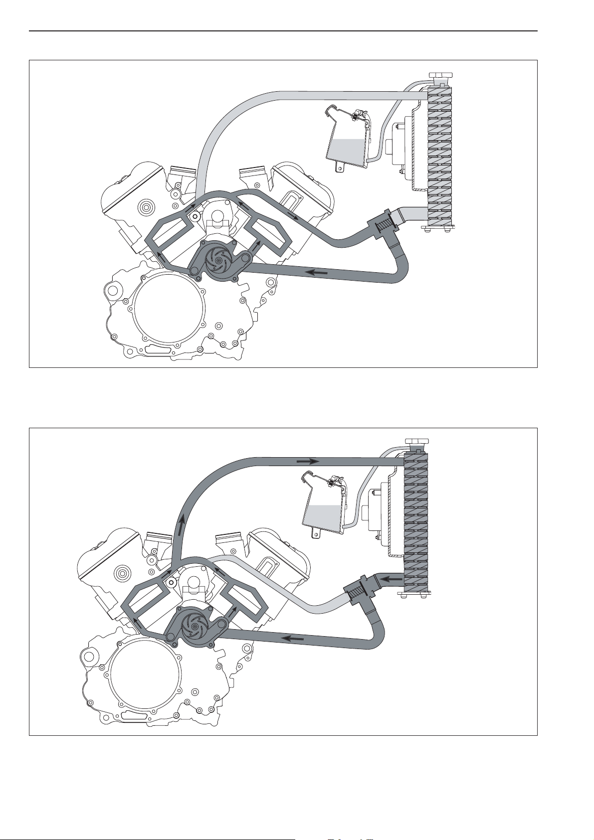
Closed thermostat
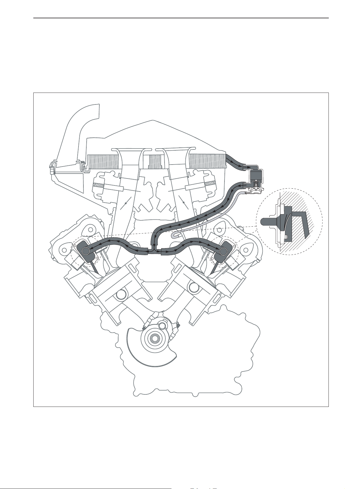
The thermostat is closed if the temperature of the cooling liquid drops below 75° C. The water pump 1 pumps the cooling liquid
through the cylinder and cylinder heads
2 and the thermostat 2.
Open thermostat
The thermostat 3 opens at 75° C. The water pump 1 pumps the cooling liquid through the cylinder and cylinder heads 2, the
aluminum cooler
4 and the thermostat. The pressure in the cooling system (max. 1.4 bar) is regulated by a valve in the radiator
cap
5. The cooling liquid level in the compensating tank 6 must be between the MIN and MAX marks when the engine is cold.
The fan
7 switches on at 102° C.
Cooling system
1
1
2
2
3
4
5
6
7
2
2
3
Page 19
2-6
Repair manual KTM LC8 Art.-Nr. 3.206.009-E
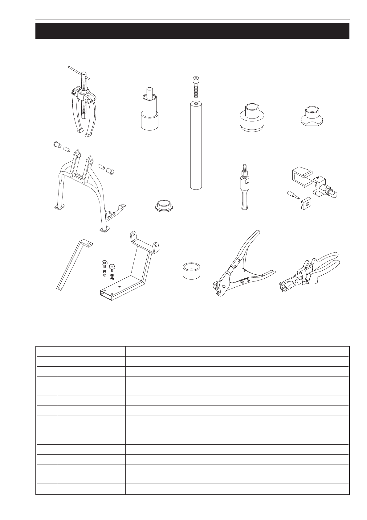
SPECIALTOOLS
– CHASSIS
FIG PART NO DESCRIPTION
1 151.12.017.000 Gear puller
2 584.29.086.000 Pressing tool for swing arm bearing
3 584.29.089.000 Chassis tool holder
4 584.29.091.000 Press-in tool for
bearing seat / rear wheel bearing
5 584.29.092.000
Knock-out tool for bearing seat
6 600.03.022.000 Center stand
7 600.10.013.000 Sleeve for pressing tool for swim arm bearing
8 600.29.018.000 Internal gear puller 28 mm
9 600.29.020.000 Chain rivet tool
10 600.29.055.000 Center stand lock
11 600.29.055.100 Floor jack attachment
12 600.29.056.000 Anvil dolly (for 584.29.086.000)
13 600.29.057.000 Pliers for Öttiker clamps
14 600.29.057.100 Pliers for spring-loaded band-type clamp
1
6
2
3
7
4
8
5
9
bl
bk
bn
bo
bm
Page 20
2-7
bm
5
1
8
6
648
2
bl
9
LOCTITE
3
4
7
243
bn
bo
bp
bq
bk
br
bt
ck
cm
dl
cn
co
dm
bs
cp
dn
cq
do
cr
dp
cs
ct
dq
cl
dk
dr
Page 21

2-8
Repair manual KTM LC8 Art.-Nr. 3.206.009-E
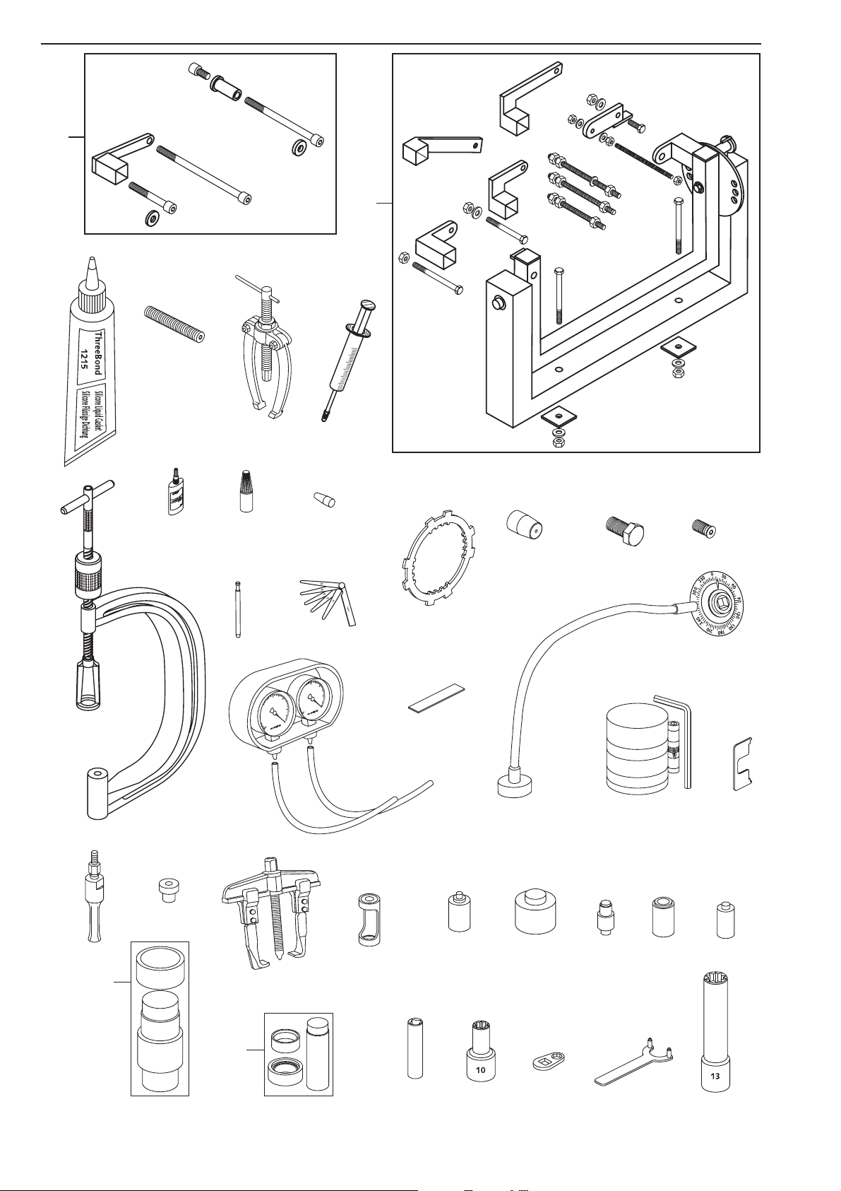
SPECIAL TOOLS
– ENGINE
FIG PART NO DESCRIPTION
1 309098 Seal Three-Bond
2 0113 080802 Crankshaft locking bolt
3 151.12.017.000 Gear puller
4 503.29.050.000 Bleeding syringe for hydraulic clutch
5 560.12.001.000 Universal-engine work stand
6 584.29.059.000 Loctite 648 green 20 ml
7 585.29.005.000 Protection sleeve for shaft seal ring of water pump
8 590.29.019.000 Valve spring mounter
9 590.29.026.006 Limit plug gauge 6,05 mm
10 590.29.041.000 Feeler gauge for valve clearance
11 6 899 785 Loctite 243 blu 6 cm3
12 600.29.002.000 Engine holder for engine work stand
13 600.29.003.000 Clutch holder
14 600.29.005.000 Protection sleeve for shaft seal ring of output shaft
15 600.29.009.000 Magneto extractor
16 600.29.009.010 Protection bolt for magneto extractor
17 600.29.010.000 Degree wheel
18 600.29.011.000 Carburator synchronisation tool
19 600.29.012.000 Plastigauge-measuring strips
20 600.29.015.000 Piston ring mounting tool
21 600.29.016.000 Setting gauge for float level
22 600.29.018.000 Internal gear puller 28 mm
23 600.29.031.000 Protection sleeve for crankshaft (for pulling of the primary gear)
24 600.29.033.000 Puller for primary gear
25 600.29.041.000 Valve spring mounter insert
26 600.29.043.010 Pressing tool for seal of clutch release shaft
27 600.29.043.020 Pressing tool for seal of output shaft
28 600.29.043.030 Pressing tool for seal and bearing of shifting shaft
29 600.29.043.040 Pressing tool for seal of water pump
30 600.29.043.050 Pressing tool for seal of balancer shaft
31 600.29.044.050 Pressing tool for main bearings (In/out)
32 600.29.046.028 Pressing tool for supporting bearing (In)
33 600.29.073.000 Spark plug wrench 16 mm
34 600.29.075.000 Special nut for conrod
35 600.29.081.000 Special tool for cylinder head nuts
36 600.29.082.000 Holder for water pump wheel
37 600.29.083.000 Special nut for cylinder head nuts
Page 22
2-9
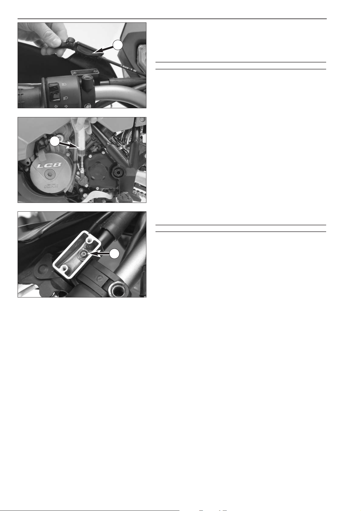
Checking the oil level of the hydraulic clutch
To check the oil level in the master cylinder of the clutch remove the
cover. For this purpose, remove bolts and cover together with the rubber
boot
1. The oil level in the horizontal-standing master cylinder should
be 4 mm below the upper edge. If necessary add SAE 10 biodegradable
hydraulic oil (e.g. Motorex Kupplungs-Fluid 75).
!
CAUTION
!
O
NLY USE SAE 10 BIODEGRADABLE HYDRAULIC OIL TO REFILL THE MASTER
CYLINDER
.
NEVER USE BRAKE FLUID NOR MIX BIODEGRADABLE HYDRAULIC OILS WITH
MINERAL OILS
!
Bleeding of the hydraulic clutch
For bleeding, the cover of the master cylinder of the clutch needs to be
removed. For this purpose, remove bolts and take off cover together
with rubber bellows
1. At the slave cylinder of the clutch, remove the
bleeder nipple. At its place, mount the bleeder syringe
2 which is filled
with biodegradable hydraulic oil (e.g. Motorex Kupplungs-Fluid 75).
Refill oil, until oil is discharged from the bore
A of the master cylinder in
a bubble-free state. Make sure that the oil does not overflow.
!
CAUTION
!
HAVING COMPLETED THE BLEEDING PROCEDURE, YOU HAVE TO VERIFY THAT THE OIL
LEVEL IN THE MASTER CYLINDER IS CORRECT
. FOR FILLING OF THE MASTER CYLINDER,
USE
SAE 10 BIODEGRADABLE HYDRAULIC OIL ONLY
(
EX. MOTOREX KUPPLUNGS-
F
LUID 75); NEVER USE BRAKE FLUID NOR MIX BIODEGRADABLE HYDRAULIC OILS WITH
MINERAL OILS
.
A
1
2
Page 23

REMOVING AND REFITTING ENGINE
Repair manual KTM LC8
Art.-Nr. 3.206.009-E
REMOVING THE ENGINE . . . . . . . . . . . . . . . . . . . . . . . . . . . . . . . . . . . . . . .3-2
REFITTING THE ENGINE . . . . . . . . . . . . . . . . . . . . . . . . . . . . . . . . . . . . . . . .3-7
INDEX
3-1
3
Page 24

Page 25
3-2
Repair manual KTM LC8 Art.-Nr. 3.206.009-E
Removing the engine
– Screw the center stand 600.03.022.000 onto the frame 1 and jack
up the motorcycle on a firm, even surface.
– Remove the left bump rubber and lock the center stand with the lock
600.29.055.000
2.
NOTE: if available, use the center stand already on the bike.
– Unlock the seat lock with the ignition key and remove.
– Remove the bolts
3 on the left and right of the front side covers,
disconnect the front turn signal, pull the tank vent hoses off of the
fuel tank and remove the side covers.
– Open the tank cover, unscrew the fixing bolts
4 and remove the
upper tank compartment.
– Remove the bolts
5 on the lower tank compartment and the fuse
box, take the cover off the fuse box and dismount the lower tank
compartment.
– Close the fuel cocks, disconnect the gasoline hoses, unscrew the
upper
6 and lower 7 fixing bolts on both fuel tanks and remove the
tanks together with the lower vent hoses.
NOTE: it is easier to disconnect the gasoline hoses if you remove the
front bolts on the underride protection and fold the engine guard down.
– Drain the engine oil from the oil tank and the engine: see page 12-4.
– Remove the 4 bolts
8 on the underride protection and take off the
underride protection.
– Remove both bolts
9 on the front cover and take off the cover.
– Open the lid on the battery compartment and disconnect the battery
terminals
bk (starting with the negative pole).
– Take out the battery and remove the upper battery cover.
1
1
2
3
3
3
4
4
5
5
5
5
6
6
7
8
8
9
10
10
Page 26
3-3
– Unscrew the bolts 1 and remove the intake snorkel 2 together with
the frame from the air filter box.
– Disconnect the vent hose and the EPC hose and remove the upper
half of the air filter box.
– Turn the intake trumpet
3 in a clockwise direction and remove.
Remove air filter.
– Unbolt both side covers on the lower air filter box and remove the
clamps on the carburetor connection boot.
– Detach the EPC hoses
4 from both carburetors and pull the hoses
out of the lower air filter box.
– Remove both vent hoses from the carburetors.
– Lift both carburetors, carefully draw the cable for the idle speed
adjustment and the gasoline hose through the openings in the lower
air filter box.
– Detach the fuel hoses from the carburetors.
– Pull the carburetor connection boots off of the intake manifolds.
– Detach the SLS valve
5 from the lower air filter box, pulling the thin
hose from the intake manifold and the thick hose from the valve.
Remove the valve.
– Remove the EPC valve
6 from the lower air filter box and
disconnect.
–Tilt up the carburetors and fasten to the handlebar with a wire or
rubber band. They do not need to be completely dismounted.
– Take the lower air filter box out of the frame.
NOTE: cover the intake ports with a cloth to prevent any parts from
falling inside.
– Unscrew both nuts
7 on the front exhaust manifold flange on the
cylinder head, loosen the exhaust clamp
8 on the front exhaust
manifold, pull the front exhaust manifold out of the rear exhaust pipe
and remove.
– Unscrew the rear exhaust manifold from the cylinder head.
6
4
4
5
7
2
1
3
8
Page 27

3-4
Repair manual KTM LC8 Art.-Nr. 3.206.009-E
– Disconnect the electric connections from the fan motor and the
temperature switch
1.
– Drain the cooling liquid from the radiator and engine: see
page 12-16.
– Detach the water hoses from the radiator (special pliers
600.29.057.100) and unscrew the radiator
2 .
NOTE: fan and radiator shield do not need to be dismounted from the
radiator.
– Pull off the oil lines from the oil tank to the valve covers
3 and the
return line
4 (special pliers 600.29.57.100), unscrew the oil lines
from the oil terminal
5 and pull out. Remove the O-rings.
– Loosen the fixing bolts
6 on the oil tank, remove the oil tank and
carefully pull out the oil line.
– Disconnect the side stand switch
7 and take the cable out of the
cable clips.
– Loosen the two bolts and the nut
8 and remove the side stand.
– Unscrew the clutch slave cylinder
9 and the chainguard bk and pull
the locking pin out of the pushrod.
– Dismount the chain roller and chain securing guide.
1
2
2
2
3
4
5
6
6
7
8
9
10
Page 28
3-5
– Unscrew the nut on the wheel spindle, pull out the rear wheel
spindle, take the chain off of the rear sprocket and place over the side
of the bracket
1. Remove the chain from the engine sprocket.
– Detach the connector
2.
– Remove the engine vent hose
3, discarding the hose clamp.
– Unscrew the positive starter engine cable and draw out the wiring
harness.
– Detach connector
4 on the starter relay.
– Pull out the gasoline pump vent hose
5 towards the bottom.
– Unscrew the ground connection
6.
– Disconnect the fuel hose
7.
– Loosen the bolts on the side support
8 and the nut on the bolt 9,
pull out the bolt and remove support together with the battery case.
– Unscrew the front oil line
bk.
1
2
2
2
4
4
3
5
6
7
8
8
9
10
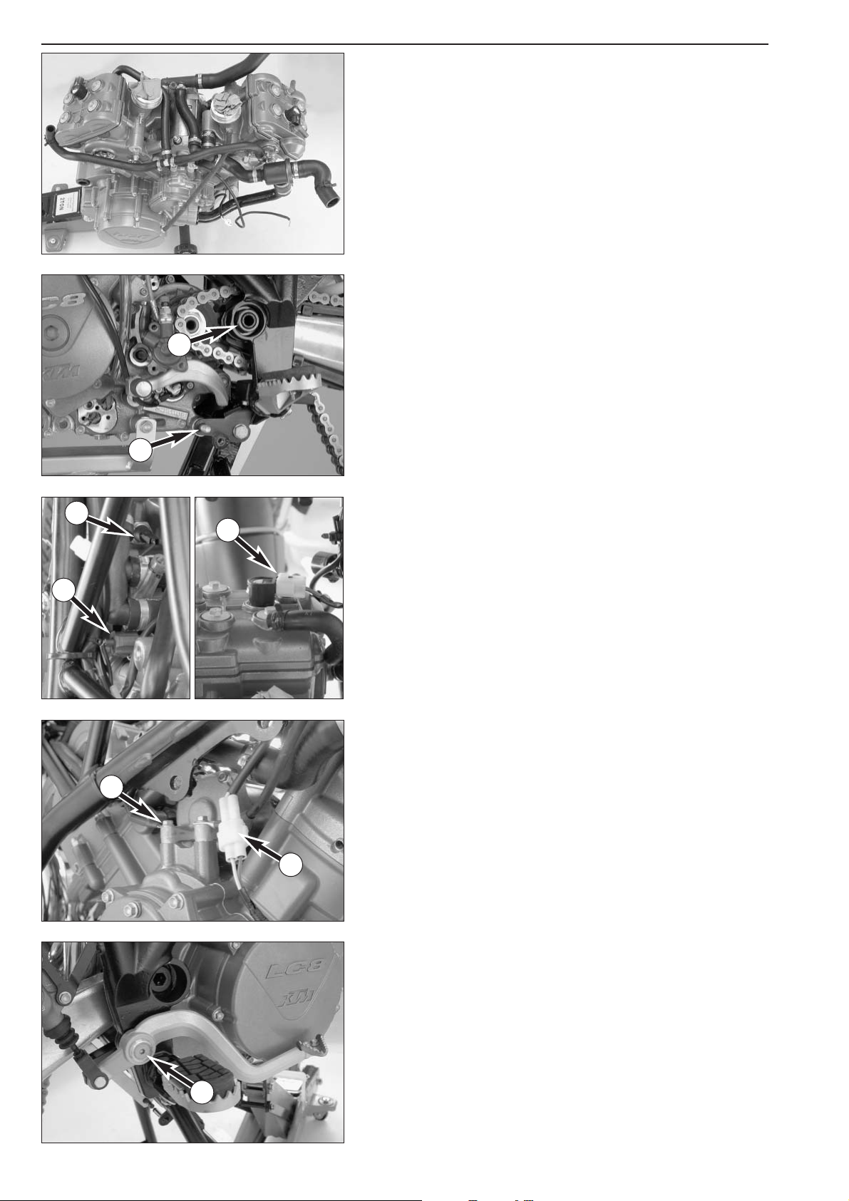
Page 29
3-6
Repair manual KTM LC8 Art.-Nr. 3.206.009-E
– Use the trolley jack to position the attachment 600.29.055.100 on
the engine, insert the bolt
1 through the front of the engine bracket
and fasten with the nut. Screw one of the bolts
2 on the rear of the
side stand fixture and slightly lift the engine.
– Remove the bolt 3 and tilt the foot brake pedal to the side.
– Unscrew the ground wire connection
4.
– Detach the connector from the pulse generator
5.
– Detach the connector from the oil pressure switch
6, the
temperature sensor
7 and from the front 8 and rear ignition coil.
Remove any cable clips necessary.
– Pull the bolt
9 out of the lower support (if necessary, raise or lower
the engine slightly).
– Loosen the nut on the swing arm pivot
bk and knock out the swing
arm pivot with a suitable pipe.
– Pull the engine towards the front with the trolley jack, lower and pull
away towards the side.
– Disconnect all hoses and lines from the engine.
1
2
3
4
5
6
7
8
9
10
Page 30
3-7
Refitting the engine
– Before mounting the engine, attach the water, SLS and vacuum hoses
(Öttiger clamps - special pliers 600.29.057.000 or spring-loaded
band-type clamps - special pliers 600.29.057.100)
– Position the swing arm and fix with the swing arm pivot on the right
and a suitable pipe on the left.
– Lift the engine into the frame with the trolley jack, insert the sealing
washer in the rear exhaust flange and secure with copper paste if
necessary.
– Guide the chain along the side of the pinion and insert the swing arm
pivot
1, screw on the nut but do not tighten yet.
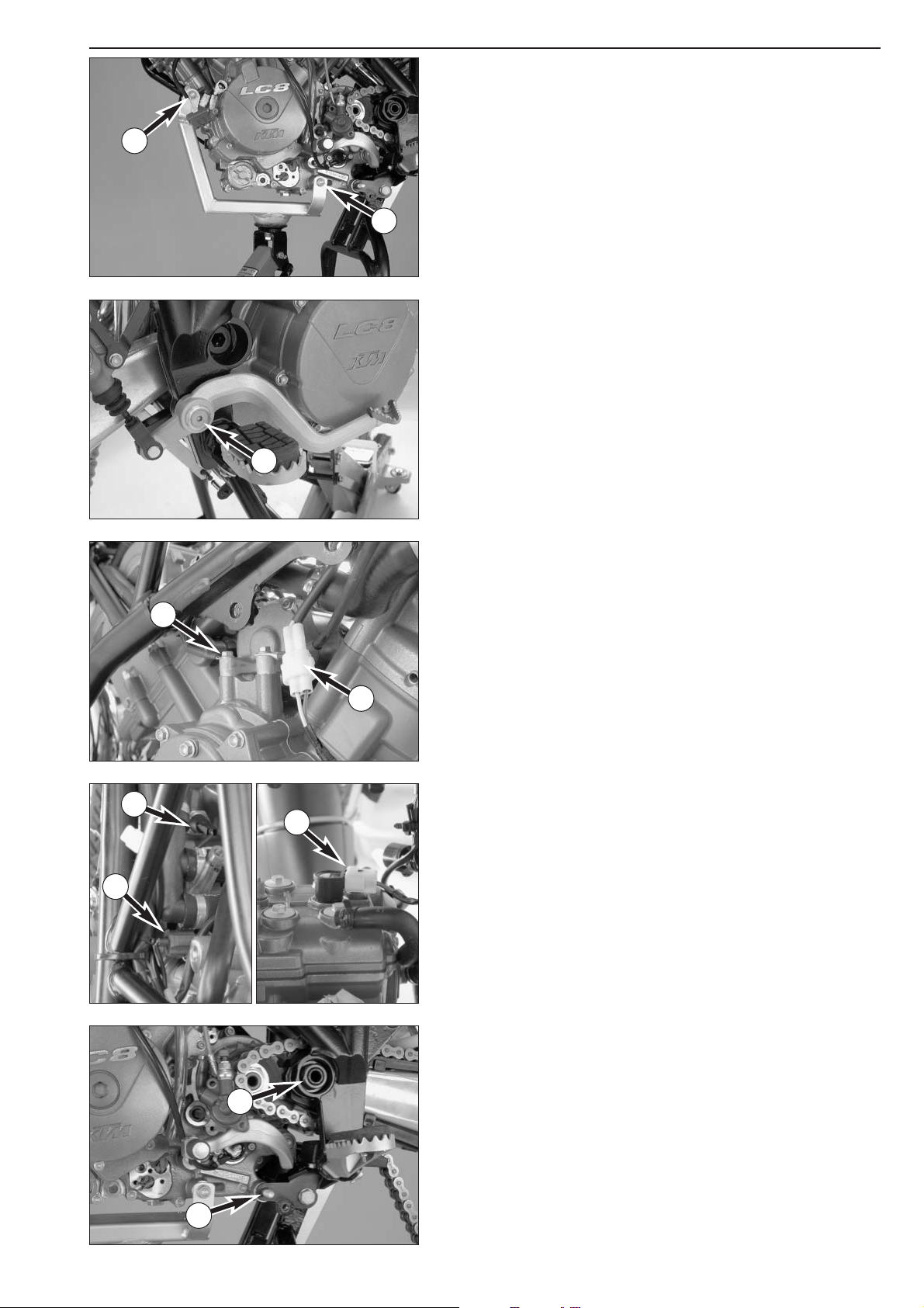
– Insert the bolt
2 in the lower support (raise or lower the engine
slightly if necessary).
– Remove the trolley jack attachment 600.29.055.100 from the engine.
– Plug the connector on the oil pressure switch
3, the temperature
sensor
4 and the front and rear ignition coil 5. Use cable clips to
fasten the wiring harnesses.
– Screw on the ground wire connection
6.
– Attach the pulse generator connector
7.
– Position the foot brake pedal, apply Loctite 243 to the bolt
8 and
tighten to 25 Nm.
1
2
3
4
5
6
7
8
Page 31

3-8
Repair manual KTM LC8 Art.-Nr. 3.206.009-E
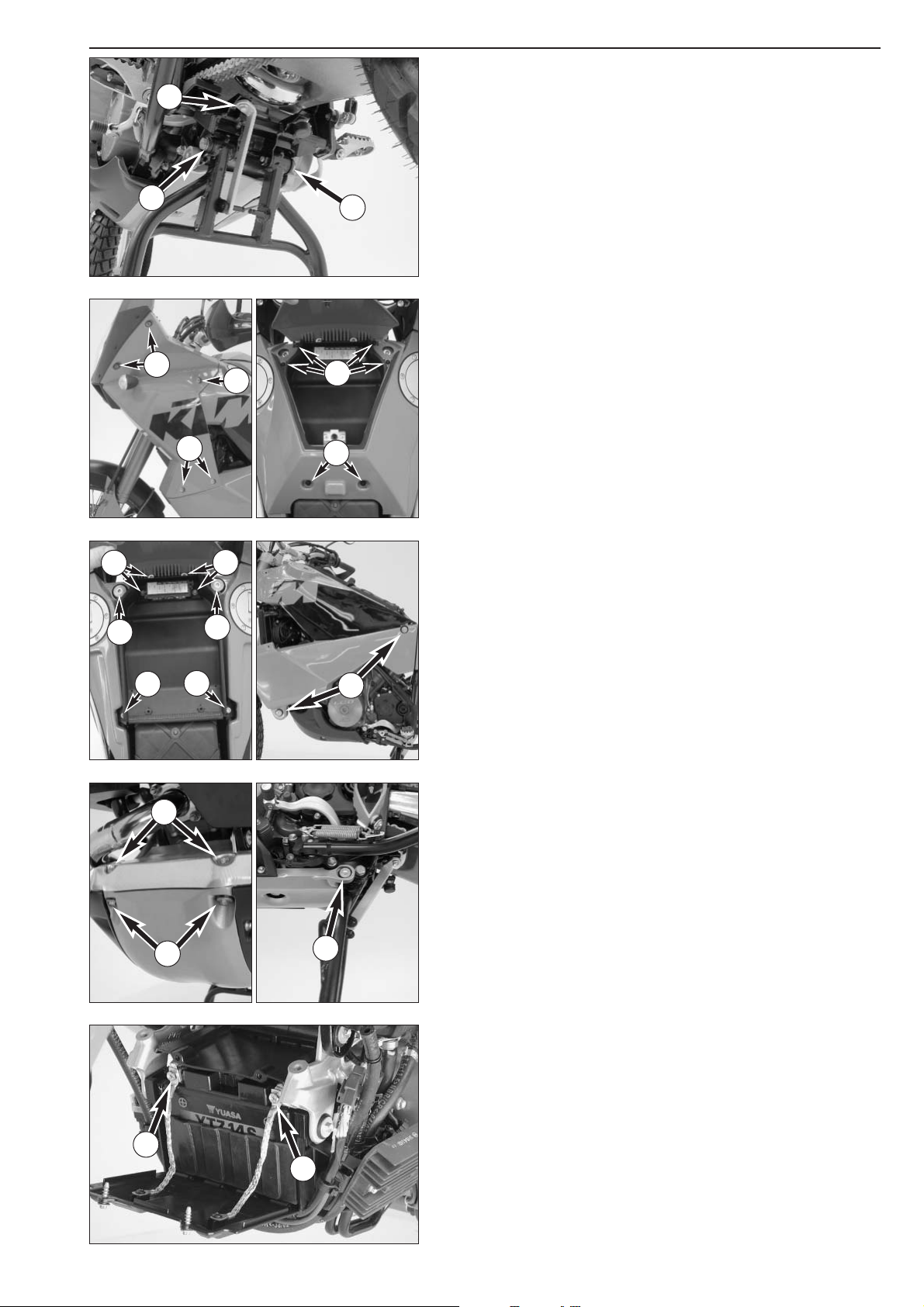
– Mount the front oil line 1 inserting new O-rings. Tighten the bolts.
– Align the side supports and battery case against the engine, insert the
bolt
2 and mount the nut.
– Mount the bolts
3 ( M10x23), lifting the engine slightly if necessary.
Tighten the nut and bolts to 40 Nm.
– Tighten the nut on the swing arm pivot to 130 Nm.
– Connect the fuel hose
4 and fasten with a cable clip.
– Run the positive starter cable to the starter and screw on the starter
engine. Run the starter ground to the battery case.
– Attach both starter relay connectors
5.
– Run the gasoline pump vent hose
6 upwards along the wiring
harness to the engine bracket and back down, forming an arch.
!
CAUTION
!
I
F YOU RUN THE HOSE STRAIGHT UP WITHOUT AN ARCH, WATER WILL BE ABLE TO
PENETRATE
, CAUSING THE GASOLINE PUMP TO BE SOILED AND DAMAGED.
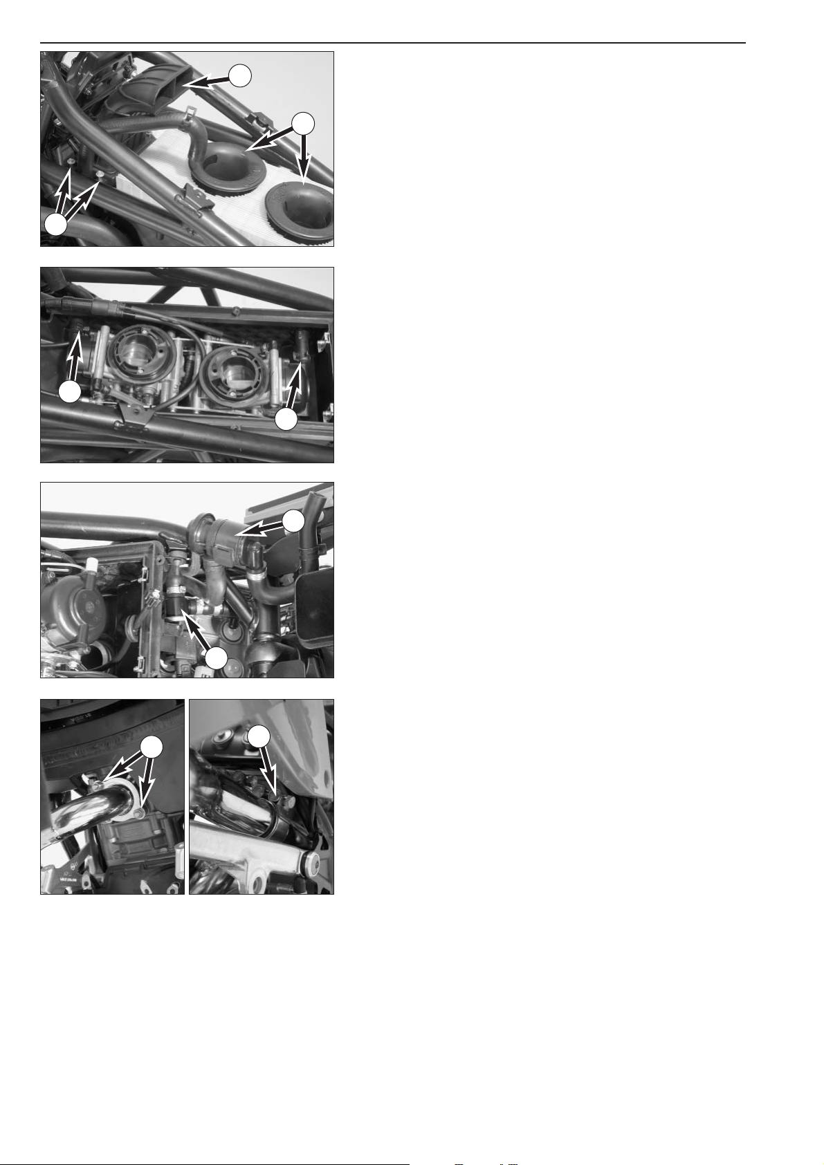
– Screw on the ground wire
7 from the regulator.
– Attach the connector
8.
– Slip on the hose from the engine ventilation
9 and mount the new
Öttiker clamp with the special pliers 600.29.057.000.
1
5
5
6
2
3
3
4
7
8
8
8
9
Page 32

3-9
– Place the chain over the pinion and rear sprocket, lift the rear wheel
and slide the wheel spindle through.
– Press the rear wheel towards the front to apply the chain tensioner
1
and tighten the nut on the wheel spindle to 110 Nm.
– Actuate the foot brake pedal to apply the brake shoes against the
brake disk.
– Check the chain tension, see owners manual, page 25.
– Mount the chain securing guide and the chain roller.
– Insert the locking pin in the pushrod and mount the clutch slave
cylinder
2. Screw on the chainguard 3.
– Position the side stand and tighten the two bolts and the nut
4
to 45 Nm.
– Mount the side stand switch
5 and fasten the cable with the cable
clips.
– Carefully install the oil line, mount the oil tank and tighten the fixing
bolts
6.
– Connect the return line
7 to the oil tank and mount the spring-
loaded band-type clamp with the special pliers 600.29.057.100.
– Attach the oil lines from the oil tank to the valve covers
8 (special
pliers 600.29.057.100).
– Mount both oil lines on the oil terminal
9 with new O-rings, insert
the bolts (M6x20) in the retaining brackets bk and tighten to 10 Nm.
6
2
3
4
7
8
9
6
5
10
10
1
1
Page 33

3-10
Repair manual KTM LC8 Art.-Nr. 3.206.009-E
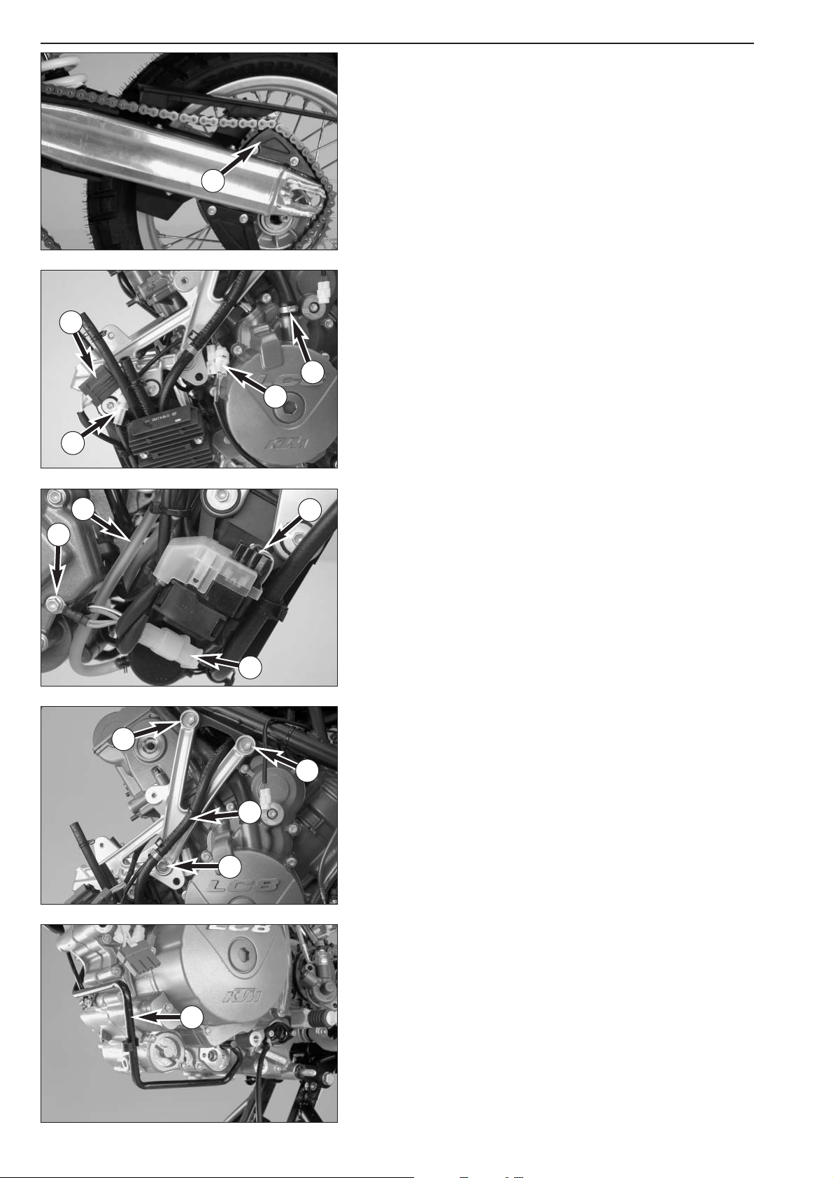
– Screw on the radiator together with the fan and the radiator shield
1, tighten the bolts to 10 Nm.
– Connect the water hoses on the radiator (special pliers
600.29.057.100)
– Attach the electric connections for the fan motor and the temperature
switch
2.
– Screw the rear exhaust manifold on to the cylinder head.
– Insert the front exhaust manifold in the rear exhaust pipe, mount to
the front cylinder head together with the sealing washer and tighten
the exhaust nuts
3.
NOTE: the exhaust nuts should be tightened evenly without bending the
metal sheet.
– Tighten the exhaust clamp
4 on the front manifold.
– Mount the lower air filter box on the intake ports, connect the drain
hose and push the fuel hose and the cable for the idle speed
adjustment down through the opening in the lower air filter box.
!
CAUTION
!
–
MAKE SURE THERE ARE NO KINKS IN THE CARBURETOR VENT HOSES AND RUN
THEM DOWN BEHIND THE STARTER ENGINE WITHOUT FORMING AN UPWARD
ARCH
.
–
REMOVE THE CLOTH USED TO COVER THE INTAKE PORTS.
– Mount the EPC valve
5 on the lower air filter box and connect.
– Mount the secondary air system valve
6 on the lower air filter box,
connecting the thin hose to the intake manifold and the thick hose
directly to the valve.
– Attach the carburetor connection boots to the intake manifold.
NOTE: the clamps on the carburetor connection boots must be aligned
so that they can be tightened through the openings in the side covers.
– Connect the fuel hoses to the carburetors.
NOTE: to make it easier to connect the fuel hoses, disconnect the fuel
hose from the connecting piece (on the side of the engine brace) and
pull the fuel hose up. Reconnect after mounting the carburetor.
–Insert the carburetor in the carburetor connection boots, tighten the
clamps on the carburetor connection boots and screw both side
covers on the lower air filter box.
– Connect both vent hoses to the carburetors and fasten the choke
cable
7 with a cable clip (see photo).
– Insert the EPC hoses
8 in the corresponding openings in the lower air
filter box and connect to the carburetors.
– Mount the air filter, position the intake trumpet
9 and turn in a
counter-clockwise direction.
– Mount the intake snorkel
bk with the frame to the filter housing.
– Screw on the upper air filter box half. Connect the vent hose and the
EPC hose.
1
2
1
1
3
4
6
5
7
8
8
9
10
Page 34

3-11
– Fit the upper battery cover and place a battery with battery cover into
the battery compartment.
– Fit the front battery compartment lid and connect both battery cables
1 together to the connections on the front lid (start with the positive
cable).
– Close the front battery compartment lid.
– Mount the underride protection, apply Loctite 243 to the 4 bolts 2
(M8x14 collar bolts) and tighten to 25 Nm.
– Mount the front cover, apply Loctite 243 to both bolts
3 (M8x16)
and tighten to 25 Nm.
– Mount the lower tank compartment and screw on the fuse box
4.
Mount the fuse box cover.
– Fill cooling liquid into the radiator, compensating tank and engine:
see page 12-16.
– Add engine oil: see page 12-5.
– Connect the fuel sender to the right tank. Connect the gasoline and
vent hoses and mount the tanks.
– Screw in the upper
5 (M8x40) and lower 6 (M8x55) or 7 (M8x50)
fixing bolts and open the fuel cocks.
– Connect the front turn signal and attach the vent hoses to the tanks.
Fasten both side covers with the bolts
8 and tighten.
– Mount the upper tank compartment and fasten with the bolts
9.
– Close the tank compartment lid and mount the seat.
– Remove the center stand lock
bk 600.29.055.000, remount the left
bump rubber and remove the center stand
bl.
– Check all hose connections for leakage before you take a trial run.
– Check all hoses, lines and cables for a proper fit.
2
2
3
5
5
4
4
4
4
6
1
1
7
8
8
8
9
9
10
11
Page 35

DISASSEMBLING THE ENGINE
Repair manual KTM LC8
Art.-Nr. 3.206.009-E
VALVE COVERS . . . . . . . . . . . . . . . . . . . . . . . . . . . . . . . . . . . . . . . . . . . . . . .4-2
SPARK PLUG SHAFT INSERTS . . . . . . . . . . . . . . . . . . . . . . . . . . . . . . . . . . . .4-2
STARTER MOTOR . . . . . . . . . . . . . . . . . . . . . . . . . . . . . . . . . . . . . . . . . . . . .4-2
SETTING CYLINDER REAR TO TDC . . . . . . . . . . . . . . . . . . . . . . . . . . . . . . .4-3
CAMSHAFTS CYLINDER REAR . . . . . . . . . . . . . . . . . . . . . . . . . . . . . . . . . . .4-3
CHAIN TENSIONER CYLINDER REAR . . . . . . . . . . . . . . . . . . . . . . . . . . . . . .4-4
TIMING CHAIN CYLINDER REAR . . . . . . . . . . . . . . . . . . . . . . . . . . . . . . . . .4-4
DOUBLE TIMING GEAR . . . . . . . . . . . . . . . . . . . . . . . . . . . . . . . . . . . . . . . .4-5
CYLINDER HEAD REAR WITH CYLINDER . . . . . . . . . . . . . . . . . . . . . . . . . . .4-5
SETTING CYLINDER FRONT TO TDC . . . . . . . . . . . . . . . . . . . . . . . . . . . . . .4-5
CAMSHAFTS CYLINDER FRONT . . . . . . . . . . . . . . . . . . . . . . . . . . . . . . . . . .4-6
OIL PRESSURE SWITCH . . . . . . . . . . . . . . . . . . . . . . . . . . . . . . . . . . . . . . . .4-6
CHAIN TENSIONER CYLINDER FRONT . . . . . . . . . . . . . . . . . . . . . . . . . . . .4-6
TIMING CHAIN CYLINDER FRONT . . . . . . . . . . . . . . . . . . . . . . . . . . . . . . . .4-7
CYLINDER HEAD FRONT WITH CYLINDER . . . . . . . . . . . . . . . . . . . . . . . . .4-7
WATER PUMP . . . . . . . . . . . . . . . . . . . . . . . . . . . . . . . . . . . . . . . . . . . . . . . .4-8
OIL SCREEN . . . . . . . . . . . . . . . . . . . . . . . . . . . . . . . . . . . . . . . . . . . . . . . . .4-8
CLUTCH COVER . . . . . . . . . . . . . . . . . . . . . . . . . . . . . . . . . . . . . . . . . . . . . .4-8
CLUTCH . . . . . . . . . . . . . . . . . . . . . . . . . . . . . . . . . . . . . . . . . . . . . . . . . . . .4-9
PRIMARY PINION AND CLUTCH . . . . . . . . . . . . . . . . . . . . . . . . . . . . . . . .4-10
GENERATOR COVER . . . . . . . . . . . . . . . . . . . . . . . . . . . . . . . . . . . . . . . . .4-11
ROTOR . . . . . . . . . . . . . . . . . . . . . . . . . . . . . . . . . . . . . . . . . . . . . . . . . . . .4-11
FREEWHEEL . . . . . . . . . . . . . . . . . . . . . . . . . . . . . . . . . . . . . . . . . . . . . . . .4-11
BALANCER SHAFT . . . . . . . . . . . . . . . . . . . . . . . . . . . . . . . . . . . . . . . . . . .4-11
SHIFT MECHANISM . . . . . . . . . . . . . . . . . . . . . . . . . . . . . . . . . . . . . . . . . .4-12
ENGINE CASE HALF . . . . . . . . . . . . . . . . . . . . . . . . . . . . . . . . . . . . . . . . . .4-12
TRANSMISSION . . . . . . . . . . . . . . . . . . . . . . . . . . . . . . . . . . . . . . . . . . . . .4-13
OIL PUMPS . . . . . . . . . . . . . . . . . . . . . . . . . . . . . . . . . . . . . . . . . . . . . . . . .4-14
INDEX
4-1
4
Page 36

Page 37

Clean the engine thoroughly on the outside prior to disassembling.
– Clamp the engine in the work stand using the special tool
600.29.002.000.
Valve covers
– Pull out the spark plug connectors.
– Unscrew the spark plugs using the special tool 600.29.073.000.
– Remove the bolts
1 on the valve covers, remove both valve covers.
– Dismount the gaskets of the bolts, the valve covers and the spark
plug shafts
2.
Spark plug shaft inserts
– Pull the spark plug shaft inserts out of the spark plug shafts (pry out
carefully with 2 screwdrivers if necessary), remove the O-rings
3 (2
pieces for each spark plug shaft) and discard.
Starter motor
– Remove both bolts 4 and pull the starter motor out of the case. The
starter motor is sealed off with an O-ring on the case side.
4-2
Repair manual KTM LC8 Art.-Nr. 3.206.009-E
1
1
1
2
3
4
4
Page 38

Setting cylinder rear to TDC
– Unscrew the plug 1 from the generator cover to be able to turn the
crankshaft.
–Turn the crankshaft in a counterclockwise direction until the rear
cylinder is in the TDC position. The marks
2 (crosses) must coincide
with the flat outer surface of the cylinder head at the camshaft gears.
NOTE: the camshaft gears are identical for both cylinders but have
marks for cylinders rear and front. Match the respective mark to the
respective cylinder, i.e. the crosses for cylinder rear and the circles for
cylinder front.
– Remove the case bolt and screw in the special tool 0113 080802
3
to block the crankshaft.
Camshafts cylinder rear
– Check and note down the valve clearance before you dismount the
camshafts.
Valve clearance: intake 0.125 - 0.175 mm
exhaust 0.225 - 0.275 mm
– Loosen the bolts on the camshaft bearing bridge from the rear
cylinder and carefully remove the camshaft bearing bridge.
!
CAUTION
!
W
HEN TIGHTENING THE BOLTS OF THE CAMSHAFT BEARING BRIDGE, MAKE SURE THAT
THE VALVES ARE NOT ACTUATED BY THE CAMSHAFT
(SEE ILLUSTRATION), OTHERWISE
THE BEARING BRIDGE WILL BREAK
.
– Remove the camshafts from the cylinder head without tilting.
4-3
1
2
2
3
Page 39

4-4
Repair manual KTM LC8 Art.-Nr. 3.206.009-E
Chain tensioner cylinder rear
– Remove the bolt from the chain tensioner 1.
NOTE: measure the preload on the chain tensioner element before
dismounting:
– Apply the chain tensioner bolt to the chain tensioner element without
compressing the spring.
–Measure the distance between the sealing washer and the cylinder
head.
The measured value should be between 6 mm and 11 mm. If the value
is lower, the tensioning rail could be worn or the timing chain excessively
elongated. If it is higher, the engine was turned to TDC against the
running direction.
– Remove the sealing washer.
– Pull out the chain tensioner element
2.
NOTE: the housing and the tensioning piston on the chain tensioner
element are compression molded. If they fall apart during disassembly,
the chain tensioner element must be replaced.
Timing chain cylinder rear
– Loosen the bearing bolt 3 on the double timing gear and pull out of
the cylinder head together with the needle bearing. The double
timing gear will slide down slightly, relieving the timing chain.
– Remove the O-ring on the bearing bolt.
– Use a wire hook
A which you can bend from a piece of welding wire
to lift the side of the chain
4 towards the inside from the chain teeth
5 over the gear teeth 6 of the double timing gear. Hold the double
timing gear towards the outside by inserting your finger through the
hole in the bearing bolt.
1
2
A
5
3
4
6
Page 40

4-5
Double timing gear
– Lift the double timing gear out of the cylinder head, letting the chain
fall into the slot.
Cylinder head rear with cylinder
– Remove the outer nut 1.
– Loosen the cylinder-head nuts crosswise. Special nut 600.29.083.000
is required for the inside nuts
2.
– Pull the cylinder head and cylinder up until the piston-pin retainer can
be lifted out of the groove on the generator side with a suitable
screwdriver.
NOTE: the piston-pin retainer can easily be removed if the piston is held
in place by the cylinder.
–Press the piston pins out of the piston by hand and remove the
cylinder together with the piston.
– Discard the cylinder-base gasket.
Setting cylinder front to TDC
Loosen the crankshaft locking bolt and continue to turn the engine
towards the front cylinder's TDC position, keeping the timing chain on
the rear cylinder slightly tensioned and holding the conrod in the center
of the opening in the case.
!
CAUTION
!
–IF YOU DO NOT HOLD THE CHAIN, IT MAY GET JAMMED BETWEEN THE TIMING
GEAR OF THE BALANCER SHAFT AND THE TENSIONING RAIL
.
–IF THE CONROD IS NOT POSITIONED IN THE CENTER OF THE OPENING IN THE
CASE
, THE CONROD BOTTOM WILL BLOCK ON THE BALANCER SHAFT AND
PREVENT THE CRANKSHAFT FROM TURNING
.
–Turn the crankshaft until the front cylinder is in the TDC position. The
marks
3 (circles) must coincide with the flat outer surface of the
cylinder head at the camshaft gears.
– The same camshaft gears are used in both cylinders but they have
marks for cylinder rear and front. Use the camshaft gear marked with
a cross for cylinder rear and the camshaft gear marked with a circle
for cylinder front cylinder.
– Block the crankshaft again.
1
2
3
3
Page 41

4-6
Repair manual KTM LC8 Art.-Nr. 3.206.009-E
Camshafts cylinder front
– Check and note down the valve clearance before you dismount the
camshafts.
Valve clearance: intake 0.125 - 0.175 mm
exhaust 0.225 - 0.275 mm
– Loosen the bolts on the camshaft bearing bridge from the front
cylinder and carefully remove the camshaft bearing bridge.
!
CAUTION
!
WHEN TIGHTENING THE BOLTS OF THE CAMSHAFT BEARING BRIDGE
, MAKE SURE THAT
THE VALVES ARE NOT ACTUATED BY THE CAMSHAFT
(SEE ILLUSTRATION), OTHERWISE
THE BEARING BRIDGE WILL BREAK
.
– Remove the camshafts from the cylinder head without tilting.
Oil pressure switch
– Loosen the oil pressure switch 1 and unscrew. Discard sealing
washer.
Chain tensioner cylinder front
– Remove the bolt on the chain tensioner 2.
NOTE: measure the preload on the chain tensioner element before
dismounting:
– Apply the chain tensioner bolt to the chain tensioner element without
compressing the spring.
–Measure the distance between the sealing washer and the cylinder
head.
The measured value should be between 6 mm and 11 mm. If the value
is lower, the tensioning rail could be worn or the timing chain excessively
elongated. If it is higher, the engine was turned to TDC against the
running direction.
– Remove the sealing washer.
– Pull out the chain tensioner element
3.
NOTE: the housing and the tensioning piston on the chain tensioner
element are compression molded. If they fall apart during disassembly,
the chain tensionerelement must be replaced.
1
2
3
Page 42

4-7
Timing chain cylinder front
– Loosen the bearing bolt 1 on the double timing gear and pull out of
the cylinder head together with the needle bearing. The double
timing gear will slide down slightly, relieving the timing chain.
– Remove the O-ring on the bearing bolt.
– Use a wire hook
A which you can bend from a piece of welding wire
to lift the side of the chain
2 towards the inside from the chain teeth
3 over the gear teeth 4 of the double timing gear. Hold the double
timing gear towards the outside by inserting your finger through the
hole in the bearing bolt.
– Lift the double timing gear out of the cylinder head, letting the chain
fall into the slot.
Cylinder head front with cylinder
– Remove the outer nut 5.
– Loosen the cylinder-head nuts crosswise. Special nut 600.29.083.000
is required for the inside nuts
6.
– Pull the cylinder head and cylinder up until the piston-pin retainer can
be lifted out of the groove on the clutch side with a suitable
screwdriver.
NOTE: the piston-pin retainer can easily be removed if the piston is held
in place by the cylinder.
–Press the piston pins out of the piston by hand and remove the
cylinder together with the piston.
– Discard the cylinder-base gasket.
A
1
2
3
4
5
6
Page 43

Water pump
– Remove the water pump cover 1, discard the O-ring gasket.
NOTE: also remove the 2 dowel pins used to keep the water pump cover
in a central position.
– Hold the water pump wheel with special tool 600.29.082.000,
remove the bolt 2 and pull the water pump wheel 3 off of the
shaft.
NOTE:
– The bolt and the water pump wheel only need to be removed if the
water pump will be serviced. They do not need to be removed if you
are only dismounting the clutch cover.
– If the water pump wheel cannot be removed because it is being held
by residual thread adhesive, the water pump shaft and the water
pump wheel can be pressed out from the inside later.
!
CAUTION
!
I
F YOU TRY TO LOOSEN THE BOLT ON THE WATER PUMP WITHOUT USING SPECIAL
TOOL
600.29.082.000, YOU MAY BREAK THE DRIVER ON THE BALANCER SHAFT OR
WATER PUMP SHAFT
.
Oil screen
– Remove the oil screen cover 4.
–Carefully pull the oil screen
5 out of the clutch cover with a pair of
pliers.
Clutch cover
– Remove the bolts and detach the inner clutch cover together with the
outer clutch cover. Be careful not to lose the dowel pins.
NOTE:
– The outer clutch over can remain on the inner clutch cover if you also
remove the bolt
6 on the outer clutch cover.
– If the case bolt for the blocking hole is still mounted, it must also be
removed.
4-8
Repair manual KTM LC8 Art.-Nr. 3.206.009-E
1
2
3
4
5
6
Page 44

4-9
Clutch
– Remove the bolts on the clutch springs crosswise and lift off the
pressure cap.
– Pull out the clutch push rod.
– Insert a wire hook in the recess in the clutch disks and pull all of the
clutch disks out of the clutch hub.
NOTE: leave the spring washer and supporting ring in the clutch. They
will be detached together with the inner clutch hub, at which time they
can be easily removed.
– Slip on the holder for the inner clutch hub
A 600.29.003.000,
counteract the inner clutch hub and loosen the nut.
– Pull off the inner clutch hub together with the clutch pressure booster
and the underlying washer, which usually adheres to the inner clutch
hub.
NOTE: you do not need to dismount the primary pinion if you are only
replacing the outer clutch hub:
– Remove the engine locking bolt 0113 080802.
– Continue turning the crankshaft until the flat part of the pickup ring
1 coincides with the teeth on the outer clutch hub.
– Pull the needle bearing
2 out of the outer clutch hub with a suitable
screwdriver, carefully pushing the outer clutch hub back and forth.
–Press the outer clutch hub away from the primary pinion and remove.
NOTE: the gear for the oil pump drive is located on the back of the
outer clutch hub and can easily fall down.
1
2
A
Page 45

4-10
Repair manual KTM LC8 Art.-Nr. 3.206.009-E
Primary pinion and clutch
If you are completely dismounting the engine, the primary pinion must
be detached before you remove the clutch.
– Mount the special tool 0113 080802 (engine locking bolt) and hold
the crankshaft in the rear or front cylinder's TDC position.
– Unscrew the pickup
1.
– Loosen the nut
2 of the primary pinion (A/F 46 mm, LH thread) and
remove together with the washer.
– Loosen the nut
3 of the balancer shaft (A/F 30 mm) and remove
together with the washer.
– Pull the outer clutch hub away from the case until the pickup ring
4
can be removed. It is secured by a pin.
– Completely remove the outer clutch hub together with the needle
bearing.
NOTE:
– The gear for the oil pump drive is located on the back of the outer
clutch hub and can easily fall down.
– Remove the spacing washer inserted between the gear for the oil
pump drive and the bearing which may adhere to the bearing.
– Pull off the gear on the balancer shaft
5.
– Insert the pressure tool 600.29.031.000
6 in the hole in the
crankshaft and pull off the primary gear
7 from the crankshaft using
the puller 600.29.033.000.
– Remove the balance weight
8 from the balancer shaft; carefully pry
the woodruff key out of the shaft groove with a screwdriver.
– Slip off the timing chain and pull the engine sprocket off of the
balancer shaft.
– Unscrew the chain tensioning rail
9.
NOTE: if you intend to reuse the timing chain, engine sprocket and
chain tensioning rail, mark the running direction and the cylinder
allocation.
1
2
3
4
5
6
7
8
9
Page 46

4-11
Generator cover
– Loosen all of the bolts on the generator cover except the bolt on the
starter idler shaft
1 and remove the generator cover, being careful
not to lose the dowel pins. Discard the gasket.
NOTE: the rotor's magnetic retaining force will prevent the cover from
being removed easily.
– Unscrew the nut
2 and remove the engine sprocket together with
the lock washer.
Rotor
– Remove the upper starter idler gear 3.
– Remove the rotor bolt
4 and the washer.
– Screw the pressure bolt 600.29.009.010
5 in the crankshaft.
– Pull the rotor off of the crankshaft using the puller 600.29.009.000
6; remove the pressure bolt and the engine locking bolt.
Freewheel
– Remove the freewheel lock 7 and lift the freewheel 8 of the
crankshaft.
– Pull the lower starter idler gear
9 from the balancer shaft.
Balancer shaft
– Gently tap the balancer shaft off on the clutch side with a rubber
hammer.
!
CAUTION
!
–MAKE SURE THE TIMING CHAIN DOES NOT GET CAUGHT.
NOTE: a stop disk is located on the outside of the roller bearing on the
balancer shaft (on the clutch side) which should be removed before the
balancer shaft is dismounted.
– Remove the timing chain and unscrew the tensioning rail.
NOTE: if you intend to reuse the timing chain and chain tensioning rail,
mark the running direction and the cylinder allocation.
1
2
3
4
5
6
7
8
9
Page 47

Repair manual KTM LC8 Art.-Nr. 3.206.009-E
4-12
Shift mechanism
– Push the shift rail 1 away from the shift locating drum and pull out
the shift shaft
2.
– Remove the bolt
3 from the shift locating drum.
–Press the locking lever
4 down to relieve the shift locating drum 5,
remove the shift locating drum.
– Loosen the bolt and remove the locking lever
4 (not required for
further engine removal).
Engine case half
– Remove the gear shift sensor 6 with the pin and spring. Unscrew the
oil filter cover
7, discarding the gasket on the oil filter cover and the
oil filter.
– Unscrew all HH bolts accessible from the generator side.
–Tilt the case horizontally with the generator side up.
– Lift the case half of the generator side while lightly tapping the drive
shaft with a rubber hammer. If necessary, tap the drive shaft
downwards.
!
CAUTION
!
–DO NOT USE A SCREWDRIVER OR SIMILAR TOOL TO PRY THE CASE HALVES APART
SINCE THIS MAY DAMAGE THE SEALING AREAS
.
– Discard the case gasket.
– Remove the crankshaft from the case.
1
2
3
4
5
6
7
Page 48

4-13
Transmission
– Remove the oil rail 1 for the transmission lubrication. It is secured at
the bottom to keep it from twisting.
– Pull out the shift rails
2 together with the upper shift rail springs.
–Tilt the shift forks
3 to the side; watch the shift rollers 4 while you
remove the shift drum
5.
– Remove the shift forks and the lower springs of the shift rails.
– Bring the engine into a vertical position (mounting position) and
remove the lock ring
6 and washer from the countershaft.
– Simultaneously pull both transmission shafts out of the bearing seats.
NOTE: also remove the spacing washer on the countershaft which often
adheres to the bearing.
1
2
2
4
4
4
3
3
3
5
6
Page 49

Repair manual KTM LC8 Art.-Nr. 3.206.009-E
4-14
Oil pumps
– Remove the lock ring 1 from the oil pump shaft; remove the spacing
washer
2 and oil pump gear 3.
– Pull the needle roller
4 out of the pump gear and remove the washer
underneath.
– Loosen the bolts on the outer oil pump
5 (pressure pump) and
remove the oil pump housing.
NOTE: the centering pins are usually retained in the oil pump housing; if
they are retained, pull them out with pliers.
– Remove the inner oil pump
6 (suction pump).
– Remove the suction pump's inner and outer rotor (
7 and 8) from
the oil pump shaft.
– Pull the needle roller
9 out of the oil pump shaft.
– Pull the oil pump shaft and the two pressure pump rotors out of the
engine housing.
– Remove both rotors from the oil pump shaft and pull out the needle
roller.
1
2
3
4
5
6
7
8
9
Page 50

Page 51

SERVICING INDIVIDUAL COMPONENTS
Repair manual KTM LC8
Art.-Nr. 3.206.009-E
ROLLER BEARING . . . . . . . . . . . . . . . . . . . . . . . . . . . . . . . . . . . . . . . . . . . . .5-2
MAIN BEARINGS - GENERAL INFORMATION . . . . . . . . . . . . . . . . . . . . . . .5-3
REPLACING BEARING SHELLS, OUTPUT END . . . . . . . . . . . . . . . . . . . . . . .5-4
REPLACING BEARING SHELLS, GENERATOR END . . . . . . . . . . . . . . . . . . . .5-4
REPLACING THE CONROD BEARINGS . . . . . . . . . . . . . . . . . . . . . . . . . . . . .5-5
SELECTING THE BEARING SHELLS . . . . . . . . . . . . . . . . . . . . . . . . . . . . . . . .5-5
REPLACING THE SUPPORTING BEARINGS IN THE CLUTCH COVER . . . . . .5-6
OVERHAULING THE WATER PUMP . . . . . . . . . . . . . . . . . . . . . . . . . . . . . . .5-7
CHECKING THE SUCTION PUMP FOR WEAR . . . . . . . . . . . . . . . . . . . . . . .5-8
CHECKING THE PRESSURE PUMP FOR WEAR . . . . . . . . . . . . . . . . . . . . . . .5-8
BYPASS VALVE . . . . . . . . . . . . . . . . . . . . . . . . . . . . . . . . . . . . . . . . . . . . . . .5-8
DISASSEMBLING THE CYLINDER HEAD AND CHECKING
PARTS FOR WEAR . . . . . . . . . . . . . . . . . . . . . . . . . . . . . . . . . . . . . . . . . . . .5-9
CHECKING THE PISTONS . . . . . . . . . . . . . . . . . . . . . . . . . . . . . . . . . . . . . .5-10
ASSEMBLY INSTRUCTIONS FOR PISTON RINGS . . . . . . . . . . . . . . . . . . . .5-10
CHECKING THE PISTON RING END GAP . . . . . . . . . . . . . . . . . . . . . . . . . .5-10
MEASURING PISTONS + CYLINDERS, ESTABLISHING THE PISTON
MOUNTING CLEARANCE . . . . . . . . . . . . . . . . . . . . . . . . . . . . . . . . . . . . . .5-10
PISTON AND CYLINDER IDENTIFICATION . . . . . . . . . . . . . . . . . . . . . . . . .5-11
ASSEMBLING THE CYLINDER HEAD . . . . . . . . . . . . . . . . . . . . . . . . . . . . . .5-11
GENERATOR COVER . . . . . . . . . . . . . . . . . . . . . . . . . . . . . . . . . . . . . . . . .5-13
VALVE GEAR – CHECKING PARTS FOR WEAR . . . . . . . . . . . . . . . . . . . . . .5-13
CLUTCH – CHECKING PARTS FOR WEAR . . . . . . . . . . . . . . . . . . . . . . . . .5-14
SHIFT MECHANISM – CHECKING PARTS FOR WEAR . . . . . . . . . . . . . . . .5-15
PREASSEMBLING THE SHIFT SHAFT . . . . . . . . . . . . . . . . . . . . . . . . . . . . . .5-15
GENERAL INFORMATION ON SERVICING THE TRANSMISSION . . . . . . . .5-16
ASSEMBLING THE MAIN SHAFT . . . . . . . . . . . . . . . . . . . . . . . . . . . . . . . . .5-16
ASSEMBLING THE COUNTERSHAFT . . . . . . . . . . . . . . . . . . . . . . . . . . . . .5-17
CHECKING THE FREEWHEEL . . . . . . . . . . . . . . . . . . . . . . . . . . . . . . . . . . .5-18
REPLACING THE FREEWHEEL HUB . . . . . . . . . . . . . . . . . . . . . . . . . . . . . . .5-18
STARTER . . . . . . . . . . . . . . . . . . . . . . . . . . . . . . . . . . . . . . . . . . . . . . . . . . .5-18
INDEX
5-1
5
Page 52

Page 53

5-2
Repair manual KTM LC8 Art.-Nr. 3.206.009-E
Replacing the roller bearing
– Remove all bearing locking screws 1 from both case halves.
– Remove all shaft seal rings and the dowel pins from the case halves.
Heat both case halves evenly in an oven at 150° C; the roller bearings
will fall out of the case by themselves. If any roller bearings should be
left in the case, tap the case lightly on a flat wooden surface.
NOTE: the shift shaft bearing
2 must be pressed out with the pressing
tool 600.29.043.030, although this bearing is usually highly resistant to
wear.
– Replace all of the roller bearings. The new roller bearings can be
inserted by hand until flush as soon as the case temperature has
reached approx. 150° C. The roller bearings should fit tightly after
cooling down. Use a mandrel to carefully press in any bearings that
are not flush with the surface.
NOTE: the shift shaft bearing
2 must be pressed in flush with the
pressing tool 600.29.043.030.
–Press in the shaft sealing ring
3 for the push rod until flush using the
special tool 600.29.043.010.
–Press in the shaft sealing ring for the countershaft
4 until flush using
the special tool 600.29.043.020.
–Press in the shaft sealing ring for the shift shaft
5 until flush using
the special tool 600.29.043.030.
–
Apply Loctite 243 to all bearing locking screws 1 and tighten to 6 Nm.
1
1
1
1
2
3
4
5
Page 54

5-3
Replacing the main bearings-general information
NOTE:
– The bearing shells for the friction bearings are pressed in and out in a
cold state.
– Mark the position of the bearing end gap
1 on the engine case with
a felt-tip pin to facilitate reassembly.
–Press the main bearing shells out of both engine case halves from the
inside to the outside using the press mandrel 600.29.044.050
2
(smaller diameter).
Before you select the bearing shells you must measure the crankshaft.
– Measure the diameter of the two main bearing pins at 3 points that
are 120° apart using a micrometer gauge. This only applies to
crankshafts that you will continue to use.
Diameter of main bearing pin: 49.965 mm – 49.975 mm (yellow)
49.976 mm – 49.985 mm (blue)
49.986 mm – 49.995 mm (red)
NOTE:
– Use the bearing color indicated for the respective measurement.
– The crankshaft must be replaced if the measurement falls short of the
minimum diameter or if the crankshaft is worn.
– New crankshafts do not need to be measured. Use new bearings
according to the colored circles
3 marked on the crankshaft web of
the new crankshaft.
NOTE: there are 2 types of bearings for each bearing color – the
grooved bearing shell (with the lubricating groove and oil bore) is
pressed into the top of the case half of the generator end and the
smooth bearing shells (without lubricating groove) are pressed into the
bottom of the case half of the generator end and into the case half of
the output end
– Measure the bearing bores with a micrometer to ensure that the
bearing shells are seated firmly in the engine case after being pressed
in.
Nominal dimension: 54.000 mm – 54.015 mm
NOTE: if the bearing bores are too big, the engine case must be
replaced.
Measure the inner diameter of the bearings after they are pressed in to
ensure that the bearing clearance is correct.
NOTE: the inner diameter of the bearings must be measured at a 90°
angle to the bearing end gap.
The diameter of the main bearing pin must be deducted from the inner
diameters of the bearings, the difference is the radial clearance of the
main bearing.
Setpoint value for the radial clearance of the main bearing:
0.025 mm – 0.055 mm
Wear limit: 0.080 mm
Example:Inner bearing diameter measured 50.020 mm
Main bearing pin measured 49.980 mm
50.020 – 49.980 = 0.040 mm radial clearance
1
2
3
Page 55

5-4
Repair manual KTM LC8 Art.-Nr. 3.206.009-E
Replacing bearing shells, output end
– Center the new bearing shells (both smooth) with the assembling
sleeve 600.29.044.050
1. The assembling sleeve is beveled on one
side so the bearing shells can be pushed in easily. The bearing shells
should protrude 1-2 mm on the other side of the assembling sleeve to
make it easier to position them in the engine case.
– Position the bearing shells on the output end of the case such that
the end gap on the bearing shells points to the marks
2 made when
disassembling.
–Press in the bearings from the outside to the inside through the
assembling sleeve up to the stop using the press mandrel
600.29.044.050
3.
!
CAUTION
!
– ALWAYS PRESS IN BEARING SHELLS FROM THE OUTSIDE TO THE INSIDE OTHERWISE
THEY WILL NOT BE POSITIONED CORRECTLY AND THE BEARING RADII OF THE
CRANKSHAFT WEBS WILL PRESS AGAINST THE BEARING SHELLS
. THIS IS WHY THE
BEARING SHELLS ARE SEATED
2 MM BELOW THE EDGE OF THE BEARING BORE.
– THE ASSEMBLING SLEEVE SERVES AS A STOP
. IT IS NOT REMOVED UNTIL THE
BEARING SHELLS ARE SEATED IN THE CORRECT POSITION
.
Replacing bearing shells, generator end
– Center the new bearing shells (smooth – on the bottom, grooved –
on the top) with the assembling sleeve 600.29.044.050 – same
procedure as for the bearing shells, output end (see above).
– Position the bearing sleeves at the generator end of the case with the
bearing shell end gap pointing to the marks
4 made when
disassembling. Do not cover the oil bore.
–Press the bearings into the engine case half from the outside to the
inside through the assembling sleeve up to the stop using the special
tool 600.29.044.050.
!
CAUTION
!
– ALWAYS PRESS IN BEARING SHELLS FROM THE OUTSIDE TO THE INSIDE OTHERWISE
THEY WILL NOT BE POSITIONED CORRECTLY AND THE BEARING RADII OF THE
CRANKSHAFT WEBS WILL PRESS AGAINST THE BEARING SHELLS
. THIS IS WHY THE
BEARING SHELLS ARE SEATED
2 MM BELOW THE EDGE OF THE BEARING BORE.
– THE ASSEMBLING SLEEVE SERVES AS A STOP. IT IS NOT REMOVED UNTIL THE
BEARING SHELLS ARE SEATED IN THE CORRECT POSITION
.
–
IF THE BEARING SHELLS ARE INCORRECTLY ALIGNED OR IF SMOOTH BEARING
SHELLS ARE PRESSED IN ON TOP
, THE OIL SUPPLY TO THE SPRAYING NOZZLES TO
COOL THE PISTONS AND LUBRICATE THE TIMING CHAIN WILL BE INTERRUPTED
,
LEADING TO SERIOUS ENGINE DAMAGE.
NOTE:
– After replacing all friction and roller bearings, dismount the spraying
nozzles and oil nozzles and clean the oil ducts with compressed air to
make sure they are not clogged.
– Coat the friction bearings with Molycote grease.
Apply Loctite 243 to the spraying nozzles and oil nozzles and tighten to 10 Nm.
2
3
4
1
Page 56

5-5
Replacing the conrod bearings
– Clamp each conrod in a vise using protective jaws.
– Loosen the bolts
1 on the conrod bearing covers with the special
wrench socket 600.29.075.000 and remove the bearing covers.
NOTE: mark the conrod caps to ensure that each cap is mounted to the
same conrod when it is measured and assembled.
– Remove the conrod caps.
– Clean the crankshaft and blow compressed air through the lubrication
bores.
Selecting the bearing shells
Before you select the new bearing shells you must measure the conrod
journal.
– Measure the diameter of the conrod journal at 3 points that are 120°
apart using a micrometer gauge.
Diameter of the conrod journal: 41.990 mm – 42.000 mm (blue)
42.001 mm – 42.011 mm (red)
NOTE:
– Use the bearing color indicated for the respective measurement.
– The crankshaft must be replaced if the measurement falls short of the
minimum diameter or if the crankshaft is worn.
– Clamp each conrod in a vise, insert new bearing shells, position the
crankshaft with a plastigauge measuring strip
A (600.29.012.000) on
top and mount the conrod caps with the old bolts, as described
below.
!
CAUTION
!
–
INSERT THE PLASTIGAUGE MEASURING STRIPS AT A 90° ANGLE TO THE BEARING
END GAP
.
– DO NOT TURN THE CONRODS ON THE CONROD JOURNAL
.
– Unclamp the conrods and compare the width of the plastigauge
measuring strip with the information on the packing. The width of
the plastiguage measuring strip is equivalent to the bearing clearance.
Setpoint value of the conrod bearing clearance:
0.030 mm – 0.060 mm
Wear limit: 0.080 mm
– Clamp each conrod in a vise using protective jaws, apply a thin layer
of Molycote grease to the bearing shells, position the crankshaft and
mount the conrod caps with new bolts.
!
CAUTION
!
THE BEARING SHELLS SHOULD BE MOUNTED IN AN OFFSET POSITION IN THE CONROD
TO ALLOW ROOM FOR THE CRANKSHAFT RADIUS
2. IF THE CONRODS ARE
MOUNTED BACKWARDS
, THE BEARING SHELLS WILL EXERT PRESSURE ON THE RADIUS
AND BLOCK THE CONRODS
.
–Tighten the conrod bearing bolts with the special wrench socket
600.29.075.000 to 25 Nm (1st stage). The tighten to 30 Nm (2nd
stage) and finally by another 60° (3rd stage).
NOTE: use a degree wheel
3 (600.29.010.000) to make sure the
conrod bearing bolts are tightened correctly.
1
2
2
3
A
Page 57

5-6
Repair manual KTM LC8 Art.-Nr. 3.206.009-E
Replacing the supporting bearings in the clutch cover
– Pull the bearing shells out of the clutch cover using the puller
151.12.017.000 and the internal extractor 600.29.018.000
1.
– Measure the diameter of the bearing pin at 3 points that are 120°
apart using a micrometer gauge.
Diameter of the supporting bearing pin: 27.985 mm – 28.000 mm
NOTE: The crankshaft must be replaced if the measurement falls short of
the minimum diameter or if the crankshaft is worn.
– Center the new bearing shells with the assembling sleeve
600.29.046.028
2. The assembling sleeve is beveled on one side so
the bearing shells can be pushed in easily. The bearing shells should
protrude 1-2 mm on the other side of the assembling sleeve to make
it easier to position them in the clutch cover.
– Place the bearing shells on the clutch cover with the assembling
sleeve and press in the bearing shells to the stop using the press
mandrel 600.29.046.028
3.
1
2
3
Page 58

5-7
Overhauling the water pump
– Remove the washer 1 from the water pump shaft and pry the shaft
sealing ring
2 out of the case.
NOTE: if the water pump wheel cannot be removed because it is being
held by residual thread adhesive, the water pump shaft and the water
pump wheel can be pressed out from the inside after the lock ring
4 is
removed.
– Remove the outer lock ring
3 from the water pump shaft using
suitable pliers.
–Press the water pump shaft out of the bearing from the outside to the
inside. The inner lock ring
4 does not need to be removed.
– Heat the case evenly in an oven at 150° C; the old bearing will fall
out of the bearing seat by itself and the new bearing can easily be
pressed into the bearing seat by hand. The bearing should fit flush
and tightly after it cools down.
– Insert the water pump shaft in the new bearing from the inside to the
outside.
NOTE: the recess in the water pump shaft should point towards the
inside.
–Mount the lock ring
3.
– Place the protective sleeve
5 585.29.005.000 on the pump shaft and
press in a new shaft sealing ring
2 until flush using the pressing tool
600.29.043.040. Mount the washer
1.
1
2
3
4
5
2
Page 59

5-8
Repair manual KTM LC8 Art.-Nr. 3.206.009-E
Checking the suction pump for wear
– Insert both suction pump rotors in the housing.
–Use a feeler gauge
A to check the clearance between the inner and
outer rotor:
Setpoint value: 0.1 mm
Wear limit: 0.2 mm
– Use a feeler gauge
A to check the clearance between the outer rotor
and the housing:
Setpoint value: 0.2 mm
Wear limit: 0.4 mm
– Use a feeler gauge A and a straight edge B to check the axial
clearance:
Setpoint value: 0.04 mm – 0.09 mm
Wear limit: 0.25 mm
Checking the pressure pump for wear
– Insert both pressure pump rotors in the case.
–Use a feeler gauge
A to check the clearance between the inner and
outer rotor:
Setpoint value: 0.1 mm
Wear limit: 0.2 mm
– Use a feeler gauge A to check the clearance between the outer rotor
and the case:
Setpoint value: 0.2 mm
Wear limit: 0.4 mm
– Use a feeler gauge and a straight edge to check the axial clearance:
Setpoint value: 0.04 mm – 0.09 mm
Wear limit: 0.25 mm
Bypass valve
– Remove the lock ring 1 on the bypass valve using suitable pliers and
take the individual bypass valve parts out of the housing.
NOTE: the spring is pretensioned.
– Check parts for visible wear and damage.
– Measure the length of the pressure spring:
Minimum length of pressure spring: 42.0 mm
– Clean parts, oil the pistons and insert in the bore. Position the spring,
place a washer on the spring and mount the lock ring in the groove
using suitable pliers.
A
A
A
A
1
A
B
Page 60

5-9
Disassembling the cylinder head and checking parts for wear
NOTE: the illustration shows the font cylinder. The procedure for the
rear cylinder is identical.
– Pull all of the bucket tappets
1 out of the cylinder head.
NOTE:
– Note down the mounting position to ensure that the same bucket
tappet is inserted in the same bore during installation.
– The compensating washers
2 for the valve clearance (shims) usually
adhere to the bottom of the bucket tappets and should be set aside
together with the bucket tappets.
– Invert the cylinder and cylinder head and remove the three Allen bolts
3 and nuts.
–Remove the cylinder and pistons from the cylinder head and discard
the cylinder head gasket.
– Unscrew the chain guide.
–Press the valve springs together using the valve assembling tool
(590.29.019.000 with the attachment 600.29.041.000
4) and
remove the valve spring key from the valve shaft. Relieve the springs
and remove from the cylinder head.
NOTE: note down the mounting position of the valves to ensure that the
valves are mounted in the same position during installation.
– Pull the valve shaft seal off the valve shaft with pliers and remove the
valve spring washer.
NOTE: a washer (14x30x2) is located under the spring retainers for the
exhaust valve springs to increase the spring preload.
– Repeat the above procedure for the other valves.
– Clean all parts.
Sealing area
Check the spark plug thread and valve seats for damage or cracks. Use a
straight edge
A and a feeler gauge B to check the sealing area to the
cylinder for distortion. Max. distortion: 0.05 mm.
Valve seats
The valve seats may not be impacted. Width of sealing seat: intake max.
1.40 mm; outlet max. 1.40 mm. Reseat the valves if necessary.
Valves
Check the valve disk for wear and runout. The valve disk runout should
not exceed 0.03 mm. The valve seat may not be impacted. The sealing
area should be in the middle of the valve seat. The valve shaft is hardchrome-plated. Wear usually occurs at the valve guide.
Valve guides
The valve guides are checked with the limit plug gauge
C
590.29.026.006 (Ø 6.05 mm). If the limit plug gauge can easily be
pushed into the valve guide, the valve guide needs to be replaced at a
special workshop.
Valve springs
Check the valve springs for fractures or other wear. Measure the spring
length with a sliding caliper in an unloaded condition:
Minimum length of inner spring: 38.0 mm
Maximum length of outer spring: 41.3 mm
1
2
3
3
3
A
B
C
4
Page 61

5-10
Repair manual KTM LC8 Art.-Nr. 3.206.009-E
Checking the pistons
– Mark the position of the piston arrow in the cylinder to facilitate
reassembly and to ensure that the same piston is mounted in the
same cylinder again.
–Press the piston up out of the cylinder.
– Replace the piston if oil consumption is high or the piston skirt is
excessively grooved.
– If the piston is to be reinstalled:
1. Check the piston bearing surface for damage.
2. Piston ring grooves: the piston rings must move freely in the groove.
Use old piston rings or sandpaper (400 grit) to clean the piston ring
grooves.
3. Check the piston rings for damage and end gap.
4. The piston pins must move freely in the bolt hole when mounted.
Replace piston pins that are badly discolored or have visible running
marks. Place the piston pin in the conrod and check for clearance.
Maximum clearance in the conrod eye: 0.08 mm.
NOTE: the piston pin may not have any clearance when mounted and
should be easy to move when applying slight counterpressure.
Checking the piston ring end gap
– Insert the piston ring in the cylinder and align with the piston
(approx. 10 mm under the upper edge of the cylinder).
– Measure the end gap with a feeler gauge
A.
Piston ring end gap: max. 0.50 mm
If the end gap is larger than indicated above, check the cylinder for
wear. If the cylinder wear is within the tolerance limits, replace the piston
ring.
Assembly instructions for piston rings
– Mount the oil scraper ring in the lower piston ring groove with the
mark facing the piston head.
–Mount the compression ring in the middle piston ring groove with the
mark facing the piston head.
–Mount the compression ring in the upper piston ring groove with the
mark facing the piston head.
Measuring pistons and cylinders, establishing the piston
mounting clearance
–To establish cylinder wear, use a micrometer to measure the cylinder
in the middle of the bearing surface.
– Measure the X and Y axis of the cylinder diameter to establish any
ovality.
NOTE: if the Nicasil coating on the cylinder is worn but not damaged, a
replacement cylinder can be ordered from our KTM dealer/importer
(new Nicasil coating, used cylinder).
– Measure the piston at the piston skirt across the piston pin, 9 mm
from the lower edge.
Piston size I: 99.960 mm – 99.972 mm
Piston size II: 99.973 mm – 99.984 mm
Wear limit: 99.930 mm
– The piston mounting clearance is the difference between the smallest
cylinder diameter and the piston diameter.
Piston mounting clearance: 0.04 mm – 0.06 mm
Wear limit: 0.10 mm
1
A
x
y
Page 62

Piston and cylinder identification
The cylinder size 1 is impressed in the bottom of the cylinder near the
chain tunnel; 1 is size I, 2 is size II.
The piston size
2 is impressed in the top of the piston; 1 is size I, 2 is
size II.
Assembling the cylinder head
– Slide the valve spring washers 3 over the valve guides and mount
new valve shaft seals
4.
– Lubricate the valve shafts and insert the valves in their original
position in the valve guides.
NOTE: a washer (14x30x2) is located under the spring retainers for the
exhaust valve springs to increase the spring preload.
– Mount the inner and outer valve springs
5 with the spring retainers
6 and compress the springs using the valve assembling tool
(590.29.019.000 with the attachment 600.29.041.000).
–Grease the valve spring keys
7 and position on the valve shafts.
Relieve the valve springs.
–Tap the valve spring retainers to set the keys.
5-11
3
4
5
1
2
6
7
Page 63

5-12
Repair manual KTM LC8 Art.-Nr. 3.206.009-E
– Place the lubricated piston on the cylinder and clamp the piston rings
together with the piston ring clamping band 600.29.015.000
1.
– Use a plastic hammer to tap lightly on the top of the piston ring
clamping band until it is flush with the cylinder.
– Use the hammer handle to carefully tap the piston into the cylinder,
making sure the piston rings do not get caught.
!
CAUTION
!
IFTHE PISTON RINGS ARE PROPERLY CLAMPED BY THE PISTON RING CLAMPING BAND
AND THE CLAMPING BAND IS FLUSH WITH THE CYLINDER
, IT SHOULD BE EASY TO
PUSH THE PISTON INTO THE CYLINDER BY TAPPING LIGHTLY WITH THE HAMMER
HANDLE
. APPLYING MORE FORCE WILL ONLY DAMAGE THE PISTON RINGS.
– Invert the cylinder head, mount a new cylinder head gasket and put
the cylinder into position.
NOTE: the cylinder and the cylinder head are marked at the exhaust
flange
2. One or two circles are impressed on both parts
–Tighten the three Allen bolts
3 to 18 Nm (1st stage) and 23 Nm (2nd
stage).
– Mount the chain guide rail, apply Loctite 243 to the bolt and tighten
(15 Nm). Check the chain rail guide for mobility.
– Mount the bucket tappets
4 and the valve shims 5 in their original
positions in the cylinder head.
NOTE: if the valve clearance was incorrect when measured or if the
valves and valve seats were serviced or parts of the valve gear were
replaced, the thickness of the valve shims must be corrected.
1
2
2
3
3
3
4
5
Page 64

5-13
Generator cover
– Loosen the three bolts 1 on the stator.
–Tilt the cable retaining bracket
2 away from the cable with long nose
pliers
A (see small arrow) and pull out of the housing. Take the cable
duct out of the generator cover and remove the stator.
–Pry the shaft sealing ring on the balancer shaft
3 out of the
generator cover and discard.
– Remove the lock ring
4 and pull the idler with the disk and the
bearing from the bearing bolt.
– Heat the housing to 150° C. The bearing
5 will fall out of the
housing by itself.
–Press in a new bearing
5 until flush. Slide the new bearing on the
bearing bolt, slide on the idler and disk and mount the lock ring
4.
– Use the special tool 600.29.043.050 to press in the new shaft sealing
ring on the balancer shaft
3, open side first.
– Position the stator, press the cable duct in the generator cover.
– Push the retaining bracket in the recess of the housing and fit into
place. Apply Loctite 243 to the stator bolts and tighten to 10 Nm.
Valve gear – checking parts for wear
Check the teeth of the balancer shaft 6 for wear.
Check the rollers and links of the timing chain
7 for wear, damage and
smooth operation.
Check the timing chain guides
8 for wear.
Check the timing chain tensioning rails
9 for wear.
Check the teeth on both double timing gears
bk and the camshaft gears
bl for wear.
Check the camshafts and camshaft bearing positions for wear and
seizing marks.
3
1
1
2
A
4
5
6
7
7
8
8
9
9
10
10
11
11
Page 65

5-14
Repair manual KTM LC8 Art.-Nr. 3.206.009-E
Clutch – checking parts for wear
Check the thrust bearing 1 for wear.
Check the front end of the pushrod
2 for wear and blow compressed air through the holes.
Clutch springs
3 must have a minimum length of 29.0 mm (new 30.77 mm). If necessary, replace all 6 at the same time.
The clutch disks must be even.
10 steel lamella
4 – may not have any recesses.
11 lining disks 5, wear limit 2.65 mm
Inner clutch hub
6 – check the outer and inner teeth for wear.
Needle bearing
7 – check for wear.
Springs in the outer clutch hub
8
Springs dampen the drive train from the primary drive to the clutch. Check these springs in addition to performing the regular wear
tests. Try to turn the outer clutch hub when the engine is blocked – you should not feel any backlash.
Check the sides of the clutch pressure booster
9 for wear.
1
2
3
7
8
9
5
4
6
Page 66

5-15
Shift mechanism – checking parts for wear
Shift forks
1
Check the leaf for wear.
Check the driving bolt
2
for the shift drum for wear.
Shift rolls
3
Check the shift rolls for hair cracks and pressure marks. It
should be easy to turn the shift rolls on the driving bolts
2
of the shift forks.
Shift drum
4
Check the shift grooves for wear.
Check both grooved ball bearings in the shift drum for
wear.
Shift rail
5
Check for wear at the points of contact.
Check the return surface
B
on the shift rail for wear
(replace if excessively grooved).
Guide bolts
6
Check for a tight fit and wear.
Guidance
Check play (play between guide bolts and slider
max. 0.7 mm).
Preassembling the shift shaft
– Mount the shift rail on the shift shaft by engaging the guide bolt 6.
– Attach the spring
7
and slide on the plastic sleeve 8.
NOTE: the noses on the plastic sleeve will engage in the opening in the
shift rail and the shift shaft and hold the spring in place.
– Mount the return spring
9
such that the offset Aruns towards the
shift quadrant.
– Slide the disk
bk
onto the shift shaft.
A
5
7
8
9
10
1
1
1
2
3
3
4
5
6
7
8
9
10
B
Page 67

5-16
Repair manual KTM LC8 Art.-Nr. 3.206.009-E
General information on servicing the transmission
– Clamp the main shaft in the vise (use protective jaws) and remove the
gears.
– Clean and check all parts.
Use new lock rings whenever you repair the transmission.
Check the tooth profile on the transmission shafts and sliding gears for
wear.
Place the sliding gears on the transmission shafts and check whether
they run smoothly on the teeth.
Check the bearing positions on the transmission shafts.
Mount the idler gear with bearings on the transmission shaft and check
for clearance.
Check the needle bearings in the idler gears.
Assembling the main shaft
–Clamp the main shaft in the vise (use protective jaws) with the gear
facing down.
–Mount the needle bearing
1 and slide the 5th gear idler 2 over the
needle bearing with the claws pointing up.
– Mount the stop disk
3 (28.3 x 35.75 x 1.5 mm) and the lock ring 4
with the sharp edge facing up.
– Mount the 3rd and 4th gear sliding gear
5 with 4th gear (larger
outer diameter) facing down.
– Mount the stop disk
6 (22.2 x 30,2 x 1.5 mm).
–Slip on the needle bearing
7 and slide the 6th gear idler 8 over the
needle bearing with the claws pointing down.
– Slip on the 2nd gear fixed gear
9 with the collar facing down and
mount the stop disk
bk (20.2 x 28 x 1.5 mm).
Check all gear wheels for smooth operation.
1
2
3
4
5
6
7
8
9
10
Page 68

5-17
General information on servicing the transmission
– Clamp the main shaft or countershaft in the vise (use protective jaws)
and remove the gears. Pull off the bearing ring.
– Clean and check all parts.
Use new lock rings whenever you repair the transmission.
Check the tooth profile on the transmission shafts and sliding gears for
wear.
Place the sliding gears on the transmission shafts and check whether
they run smoothly on the teeth.
Check the bearing positions on the transmission shafts.
Mount the idler gear with bearings on the transmission shaft and check
for clearance.
Check the needle bearings in the idler gears. Mount the bearing ring
using a suitable tube.
Assembling the countershaft
– Clamp the countershaft in the vise (use protective jaws) with the
collar facing down.
– Oil the needle bearing
1
and mount.
– Slide the 2nd gear idler
2
with the groove facing up over the needle
bearing.
– Mount the stop disk
3
(30.2 x 39 x 1.5 mm) and the lock ring
4
with the sharp edge facing up.
– Mount the 6th gear sliding gear
5
with the shift groove facing up.
–Mount the lock ring
6
with the sharp edge facing down and the stop
disk
7
(26.2 x 36 x 1.5 mm).
– Mount the needle bearing
8
and 9and slide the 3rd gear idler
bk
over the needle bearing with the collar facing up.
– Slip on the 4th gear idler
bl
with the collar facing down.
– Mount the stop disk
bm
(26.2 x 36 x 1.5 mm) and lock ring bnwith
the sharp edge facing up.
– Mount the 5th gear sliding gear
bo
with the shift groove facing down
and the stop disk
bp
(24.3 x 35.75 x 1.0 mm).
–Mount the 1st gear idler
bq
with the groove facing down, the needle
bearing
br
and the stop disk bs(20.2 x 34 x 1.0 mm).
Check all gear wheels for smooth operation.
2
1
5
12
16
17
18
15
14
13
11
3
4
6
7
8
9
10
Page 69

5-18
Repair manual KTM LC8 Art.-Nr. 3.206.009-E
Checking the freewheel
– Insert the freewheel gear 1in the freewheel.
–You should be able to turn the freewheel gear in a counterclockwise
direction.
– The freewheel gear should block without backlash in a clockwise
direction.
– Check the reduction gear
2
and the needle bearings 3for wear,
replace if necessary.
Replacing the freewheel hub
– Remove the 6 bolts, tap the side of the freewheel hub with a plastic
hammer and remove the freewheel hub.
– Hold the components of the freewheel 4together.
– Check the segments in the freewheel for wear.
–
Check the freewheel hub 5at the freewheel running surface for wear.
– Apply Loctite 648 to the flange areas on the rotor and the freewheel
hub.
– Mount the freewheel hub on the rotor.
– Apply Loctite 648 to the thread of the bolts and tighten the bolts
crosswise to 13 Nm.
!
CAUTION
!
A
LWAYS USE NEW BOLTS
(QUALITY GRADE 12.9) AND COAT BOLT THREAD WITH
LOCTITE 648.
– Generously oil the freewheel and insert in the freewheel hub.
Starter
– Since the starter will show little wear after 10,000 starts and the
replacement of individual parts is uneconomical, these steps will not
be described in detail at this point.
– Replace the O-ring
6
on the starter flange.
1
2
3
3
5
4
6
Page 70

Page 71

ASSEMBLING THE ENGINE
Repair manual KTM LC8
Art.-Nr. 3.206.009-E
OIL PUMPS . . . . . . . . . . . . . . . . . . . . . . . . . . . . . . . . . . . . . . . . . . . . . . . . . .6-2
TRANSMISSION . . . . . . . . . . . . . . . . . . . . . . . . . . . . . . . . . . . . . . . . . . . . . .6-4
CASE HALF . . . . . . . . . . . . . . . . . . . . . . . . . . . . . . . . . . . . . . . . . . . . . . . . . .6-5
SHIFT MECHANISM . . . . . . . . . . . . . . . . . . . . . . . . . . . . . . . . . . . . . . . . . . .6-6
ALIGNING THE RETURN SPRING . . . . . . . . . . . . . . . . . . . . . . . . . . . . . . . . .6-6
BALANCER SHAFT . . . . . . . . . . . . . . . . . . . . . . . . . . . . . . . . . . . . . . . . . . . .6-7
FREEWHEEL . . . . . . . . . . . . . . . . . . . . . . . . . . . . . . . . . . . . . . . . . . . . . . . . .6-7
ROTOR . . . . . . . . . . . . . . . . . . . . . . . . . . . . . . . . . . . . . . . . . . . . . . . . . . . . .6-7
GENERATOR COVER . . . . . . . . . . . . . . . . . . . . . . . . . . . . . . . . . . . . . . . . . .6-8
TIMING CHAIN AND BALANCING WEIGHT . . . . . . . . . . . . . . . . . . . . . . . . .6-8
PRIMARY PINION . . . . . . . . . . . . . . . . . . . . . . . . . . . . . . . . . . . . . . . . . . . . .6-9
OUTER CLUTCH HUB . . . . . . . . . . . . . . . . . . . . . . . . . . . . . . . . . . . . . . . . . .6-9
CLUTCH DISKS . . . . . . . . . . . . . . . . . . . . . . . . . . . . . . . . . . . . . . . . . . . . . .6-10
CLUTCH COVER . . . . . . . . . . . . . . . . . . . . . . . . . . . . . . . . . . . . . . . . . . . . .6-11
OIL SCREEN . . . . . . . . . . . . . . . . . . . . . . . . . . . . . . . . . . . . . . . . . . . . . . . .6-12
WATER PUMP . . . . . . . . . . . . . . . . . . . . . . . . . . . . . . . . . . . . . . . . . . . . . . .6-12
CYLINDER HEAD REAR WITH TIMING CHAIN . . . . . . . . . . . . . . . . . . . . . .6-13
CHAIN TENSIONER CYLINDER REAR . . . . . . . . . . . . . . . . . . . . . . . . . . . . .6-15
CAMSHAFTS CYLINDER REAR . . . . . . . . . . . . . . . . . . . . . . . . . . . . . . . . . .6-16
SETTING CYLINDER FRONT TO TDC . . . . . . . . . . . . . . . . . . . . . . . . . . . . .6-17
CYLINDER HEAD FRONT WITH TIMING CHAIN . . . . . . . . . . . . . . . . . . . .6-17
CHAIN TENSIONER CYLINDER FRONT . . . . . . . . . . . . . . . . . . . . . . . . . . .6-19
OIL PRESSURE SWITCH . . . . . . . . . . . . . . . . . . . . . . . . . . . . . . . . . . . . . . .6-19
CAMSHAFTS CYLINDER FRONT . . . . . . . . . . . . . . . . . . . . . . . . . . . . . . . . .6-20
STARTER MOTOR . . . . . . . . . . . . . . . . . . . . . . . . . . . . . . . . . . . . . . . . . . . .6-21
SPARK PLUG SHAFT INSERTS . . . . . . . . . . . . . . . . . . . . . . . . . . . . . . . . . . .6-22
VALVE COVER . . . . . . . . . . . . . . . . . . . . . . . . . . . . . . . . . . . . . . . . . . . . . .6-22
INDEX
6-1
6
Page 72

Page 73

Clean all parts thoroughly before reassembling.
– Clamp the output-end engine case on the engine work stand and
move into a vertical position (installation position).
Oil pumps
NOTE: lubricate the oil pump rotors and the oil pump shaft prior to
installation.
– Slide the outer rotor of the pressure pump into the bore with the
mark
1 facing the engine case.
– Insert the needle roller
2 on the pressure pump in the oil pump shaft
and slide on the inner rotor
3 of the pressure pump. The mark 4 on
the inner rotor of the pressure pump must point to the groove
5 in
the oil pump shaft.
– Insert the oil pump shaft and inner rotor of the pressure pump into
the engine case.
NOTE: contrary to common practice, the two marks for the outer and
inner rotor of the pressure pump are not on the same side.
– Mount the pressure pump case
6 and fix with the short bolt 7
(M6x25) (apply Loctite 243 to the bolt but do not tighten yet). Do
not forget the centering pins on the pressure pump housing.
– Insert the needle roller in the oil pump shaft and slide on the inner
rotor
8 of the suction pump. Mount the outer rotor 9 such that the
mark
bk is visible on the outside.
NOTE: the marks for the outer and inner rotors (
bk and bl) of the
suction pump are on the same side.
– Hold the outer rotor in place while you slide the suction pump
housing bm over the rotor. Do not forget the centering pins.
– Replace the O-ring and lubricate.
6-2
Repair manual KTM LC8 Art.-Nr. 3.206.009-E
1
2
3
4
5
6
7
8
9
10
11
12
Page 74

– Apply Loctite 243 to the three remaining oil pump bolts (M6x40) and
screw in. Tighten bolts to 10 Nm.
–Slide on the disk, insert the needle roller
1 and mount the oil pump
gear
2 with the collar facing the rear.
– Slide on the spacer washer
3 and mount the lock ring 4 on the oil
pump shaft.
– Check the oil pump for smooth operation by turning the oil pump
gear.
6-3
1
2
3
4
Page 75

6-4
Repair manual KTM LC8 Art.-Nr. 3.206.009-E
Transmission
– Simultaneously push both transmission shafts into the bearing seats.
NOTE: pay attention to the spacing washer on the countershaft.
– Slide the washer on the counter shaft and mount the lock ring
1.
– Move the engine into a horizontal position.
– Insert the lower gearshift rail springs in the bores with the tapered
ends down.
– Position the shift forks
2 in the shift grooves and tilt aside, paying
attention to the shift rollers
3 – fix with grease if necessary. Mount
the shift drum
4 and allow the shift forks to engage in the shift
drum.
NOTE: since 3 different shift forks are used they cannot be confused
with each other.
– Mount the gearshift rails 5, paying attention to the lower gearshift
rail springs. Insert the upper gearshift rail springs in the gearshift rails
with the tapered ends up.
NOTE: the longer gearshift rail is used for the countershaft shift forks.
– Insert the oil rail for transmission lubrication
6 in the bore and turn
to engage the locking pin.
1
5
5
6
4
2
2
2
3
3
3
Page 76

6-5
– Position the pin and spring in the shifting drum. Mount the gear
sensor
2 with 2 M5x10 bolts. Tighten bolts to 4 Nm.
– Slide in a new oil filter and mount the oil filter cover
3 with a new
gasket. Tighten M5x16 bolts to 6 Nm.
– Insert the crankshaft in the friction bearing.
NOTE:
– The crankshaft and the thread for the primary pinion bolt connection
must point down.
– The conrod for the rear cylinder
1 must face up. Both conrods should
be in the position shown in the illustration.
– Mount the case dowel pins and put a new case gasket in place.
Case half
– Slide the protective sleeve 600.29.005.000 over the countershaft.
– Slip on the generator-end case half. Tap lightly on the countershaft
with a rubber hammer if necessary.
!
CAUTION
!
D
O NOT TRY TO DRAW THE TWO CASE HALVES TOGETHER WITH THE CASE BOLTS
.
1
2
3
– Screw in all HH case bolts (see illustration for bolt
lengths) and tighten to 10 Nm.
NOTE: the bolts should be tightened in the order
shown in the illustration (numbers in parentheses).
– Move the case into a horizontal position with the
generator side facing up.
M6x65(19)
M6x65(20)
M6x65(21)
M6x90(2)
M6x90(3)
M6x90(4)
M6x40(5)
M6x40(6)
M6x40(7)
M6x90(1)
M6x40(8)
M6x60(9)
M6x60(10)
M6x60(11)
M6x60(13)
M6x75(14)
M6x60(15)
M6x65(16)
M6x65(17)
M6x65(18)
M6x75(12)
Page 77

Shift mechanism
– Mount the locking lever 1 with the spring. Apply Loctite 243 to the
M5x20 bolt and tighten to 8 Nm.
–Press the locking lever down and mount the shift locating drum
2.
NOTE: the flat parts of the shift locating drum are off center.
– Apply Loctite 243 to the M6x30 bolt
3 and tighten to 10 Nm.
– Slide the shift shaft
4 in the bearings, push the shift rail 5 away
from the shift locating drum and press the shift shaft towards the
case to the stop; let go of the shift rail.
Aligning the return spring
– Engage second or third gear.
– Check the backlash of the shift rail and the clearance of the shift bolt.
– The backlash of the shift rail is the distance the rail travels until the
shift shaft begins to move. You should be able to feel the pressure of
the return spring. Relative to the basic position, this backlash
A
should be equal towards the top and towards the bottom.
– The backlash can be corrected by aligning the return spring.
–To align, dismount the shift shaft and bend the return spring as
needed at the bends
B using a pair of pliers. Remount the shift shaft.
When the shift shaft is installed, the return spring must rest against
the shift bolt
6 and the dolly of the shift mechanism support.
– Bend the return spring again if necessary.
6-6
Repair manual KTM LC8 Art.-Nr. 3.206.009-E
3
4
5
1
2
B
6
Page 78

6-7
3
4
– Screw on the generator-end timing chain tensioning rail 1. Apply
Loctite 243 to the bolt and tighten to 20 Nm.
!
CAUTION
!
M
AKE SURE NO LOCTITE THREAD ADHESIVE IS ON THE PIVOT AREA OF THE BOLT. THIS
COULD CAUSE THE TIMING CHAIN TENSIONING RAIL TO BLOCK AND BREAK
.
Balancer shaft
– Heat the generator-end bearings of the balancer shaft evenly with a
heat gun.
– Fit the timing chain on the generator end (pay attention to the
running direction if the chain has already been used) and slide into
the balancer shaft
2. The timing chain must be placed over the rear
sprocket.
– Attach a stop disk (22 x 29.5 x 2.4 mm) to the balancer shaft
– Check the balancer shaft for smooth operation.
Freewheel
– Slip the freewheel 3 on the crankshaft and attach the locking device
4 with 2 M6x16 bolts. Apply Loctite 243 to the bolts and tighten to
10 Nm.
– Attach the lower starter idler gear
5 to the balancer shaft with the
collar on the inside.
Rotor
– Hold the freewheel with your finger while mounting the rotor, turning
it in a counterclockwise direction.
– Mount the rotor bolt
6 with disk, apply Loctite 243 to the bolt and
tighten to 150 Nm.
NOTE: to prevent the crankshaft from turning, block it with the engine
lock bolt.
–Mount the upper starter idler gear
7 on the journal.
1
2
5
6
7
Page 79

6-8
Repair manual KTM LC8 Art.-Nr. 3.206.009-E
Generator cover
– Mount dowel pins on the engine case and put a new gasket in place.
Position the generator cover and tighten the generator cover bolts to
10 Nm (see illustration for bolt lengths).
– Mount the chain sprocket with the lock washer and tighten the nut
1 to 60 Nm.
Timing chain and balancing weight
– Screw the output-end timing chain tensioning rail 2. Apply Loctite
243 to the bolt and tighten to 20 Nm.
!
CAUTION
!
M
AKE SURE NO LOCTITE THREAD ADHESIVE IS ON THE PIVOT AREA OF THE BOLT. THIS
COULD CAUSE THE TIMING CHAIN TENSIONING RAIL TO BLOCK AND BREAK
.
– Insert the woodruff key for the chain sprocket in the shaft groove and
push the chain sprocket onto the balancer shaft. Fit the timing chain
(pay attention to the running direction if the chain has already been
used).
– Insert the woodruff key for the balancing weight in the shaft groove
and mount the balancing weight
3 with the aperture 4 towards the
front.
M6x30
M6x30
M6x30
M6x35
M6x35
M6x30
M6x30
M6x30
M6x30
1
2
3
4
Page 80

Primary pinion
–Mount the woodruff key for the primary pinion in the shaft groove (if
dismounted).
– Mount the primary pinion
1 with the longer collar facing the back.
The pin for the ring gear must face outside.
– Mount the gear wheel of the balancer shaft
2 with the collar facing
the back.
!
CAUTION
!
T
URN THE BALANCER SHAFT UNTIL THE MARKS ON GEARS FOR THE CRANKSHAFT 3
AND BALANCER SHAFT 4 COINCIDE AS SHOWN IN THE ILLUSTRATION
. MAKE SURE
THE TIMING CHAINS DO NOT GET CAUGHT
.
NOTE: when the marks coincide the first cylinder of the engine is in the
TDC position.
– Slide a 30.3 x 50 x 2 mm spacer washer
5 and a needle bearing 6
on the clutch shaft.
– Mount the gear for the oil pump drive on the back of the outer clutch
hub. The gear is secured by 3 needle rollers.
Outer clutch hub
– Slide the outer clutch hub onto the shaft, leaving enough room for
the ring gear
7, which is positioned by a pin.
!
CAUTION
!
T
HE RING GEAR HAS A MARK A WHICH FACES THE OUTSIDE.
– After mounting the ring gear on the crankshaft, push the outer clutch
hub up to the stop, moving the oil pump wheel back and forth to
make the procedure easier.
– Mount a 33.2 x 46 x 2 disk and nut
8 (A/F 46 mm) on the primary
pinion (LH thread). Apply Loctite 243 to the nut and tighten to
130 Nm.
– Mount a 20.2 x 33 x 1.5 mm disk and nut
9 on the balancer shaft.
Apply Loctite 243 to the nut and tighten to 150 Nm.
– Screw on the pickup
bk. Apply Loctite 243 to the bolts (M6x16) and
tighten to 10 Nm. Press the cable duct into the recess in the case.
NOTE: the distance between the pickup and the ring gear must be
between 0.6 mm and 1.0 mm.
6-9
2
3
5
7
8
9
1
4
6
10
Page 81

6-10
Repair manual KTM LC8 Art.-Nr. 3.206.009-E
– Slide the 25 x 48 x 6.5 mm disk and inner clutch hub together with
the clutch pressure booster onto the main shaft teeth.
NOTE: the two clutch pressure booster parts are marked with coinciding
circles.
– Attach the holder for the inner clutch hub
A 600.29.003.000. Mount
the 22 x 37 x 3 mm disk. Apply Loctite 243 to the nut (A/F 32 mm)
and tighten to 130 Nm. Remove support.
–Turn the inner clutch hub to check for smooth operation.
– Push the clutch pushrod into the transmission main shaft.
– The marks
B on the pressure cap and inner clutch hub must coincide
when the pressure cap is mounted.
– Mount the pressure springs with disks and bolts (M6x16). Tighten the
bolts crosswise to 10 Nm.
Clutch disks
– First mount the supporting plate 1 and then the
spring washer
2 with the open side facing
outwards (see illustration).
– Starting with the lining disk
3 with the largest
inner diameter, alternately insert 11 lining disks and
10 clutch disks.
NOTE:
– Thoroughly oil all disks.
– The clutch lining on the first and last clutch disks
have a different color since these two disks run on
aluminum on one side.
– The first clutch disk has a larger inner diameter to
hold the support and lining disk.
– The clutch disks are punched out. The sharp edges
on all of the disks must point in the same direction.
The round recesses (for demounting) must be in
the same meshing.
– The last lining disk must be turned one meshing
further.
3
4
1
2
A
B
B
2
Page 82

6-11
–Turn the water pump shaft 1 until the recess fits over the driver 2 of
the balancer shaft when the clutch cover is mounted.
– Mount the inner clutch cover together with the outer clutch cover,
inserting the bolts as illustrated. Tighten to 10 Nm.
– Screw the locking bolt back in.
M6x30
M6x30
M6x30
M6x85
M6x30
M6x30
M6x30
M6x35
M6x30
M6x30
Clutch cover
– Mount the dowel pins on the engine case and put
a new clutch cover gasket in place.
NOTE: remove the locking bolt to make it easier to
mount the clutch cover.
1
2
Page 83

6-12
Repair manual KTM LC8 Art.-Nr. 3.206.009-E
Oil screen
– Insert the oil screen 1 in the opening in the case.
NOTE: the oil screen has a TOP marking
2 which must point up.
– Mount the oil screen cover; tighten the two M6x35/M6x40 bolts to
10 Nm.
Water pump
– Mount the water pump wheel 3 and disk on the shaft. Hold with
the holding spanner 600.29.082.000, secure the bolt
4 M6x15 with
Loctite 243 and tighten to 10 Nm.
– Mount the dowel pins and replace the O-ring gasket.
– Mount the water pump cover 5 with 4 M6x60 bolts. Tighten to
10 Nm.
1
2
4
5
3
Page 84

6-13
Cylinder head rear with timing chain
– Mount a new base gasket.
NOTE: make sure the crankshaft is blocked in the cylinder rear TDC
position.
– Fit the timing chain and chain tensioning rail in the cylinder.
NOTE:
– The chain guide is mounted on the exhaust side of cylinder rear.
– The timing chain should be drawn up and held in the chain tunnel
with a thin welding wire
1 or a rubber band.
– Push the cylinder head and cylinder over the stud bolts until the
piston pin can be pressed into the piston by hand from the output
end. Insert a new piston pin retainer with a screwdriver into the
piston groove.
!
CAUTION
!
–D
O NOT PULL THE PISTON OUT OF THE CYLINDER UP TO THE OIL SCRAPER RING
SINCE THE PISTON RING WILL BE DAMAGED BY THE LOWER EDGE OF THE
CYLINDER
.
–T
HE OPENING TOWARDS THE CRANKSHAFT SHOULD BE COVERED WITH A CLOTH
TO PREVENT THE PISTON PIN RETAINER FROM FALLING OUT OF THE ENGINE CASE
.
–T
HE PISTON PIN RETAINER 2 MUST BE IN THE POSITION SHOWN IN THE
ILLUSTRATION
.
– Push the cylinder head and cylinder down. Mount the cylinder head
nuts.
The cylinder head nuts are tightened in 2 stages.
1st stage:
–Tighten the cylinder head nuts crosswise. Use the special nut
600.29.083.000 for the internal nuts
3 and the special wrench
600.29.081.000 for the outer nut
4.
!
CAUTION
!
–THE TIGHTENING TORQUE FOR THE 1ST STAGE IS 25 NM. SINCE THE SPECIAL
WRENCH
600.29.081.000 IS USED FOR NUT 4, IT MUST BE TIGHTENED TO 23
NM.
–T
HE TORQUE WRENCH USED MUST BE USED IN LINE WITH THE SPECIAL WRENCH
600.29.081.000 (SEE ILLUSTRATION).
–Tighten the two outer nuts
5 to 8 Nm.
2nd stage:
–Tighten the cylinder head nuts crosswise.
!
CAUTION
!
–
T
HE TIGHTENING TORQUE FOR THE2ND STAGE IS
43 NM.
SINCE THE SPECIAL WRENCH
600.29.081.000
IS USED FOR NUT
4,
IT MUST BE TIGHTENED TO
36 NM.
–THE TORQUE WRENCH USED MUST BE USED IN LINE WITH THE SPECIAL WRENCH
600.29.081.000 (SEE ILLUSTRATION).
1
3
4
2
5
5
Page 85

6-14
Repair manual KTM LC8 Art.-Nr. 3.206.009-E
– Push the double timing gear down into the chain tunnel draw the
timing chain along the side on the inside.
– Use the wire hook
A to lift the side of the chain on the inside over
the gear teeth
1 onto the chain teeth 2 of the double timing gear.
Hold the double timing gear towards the outside by inserting your
finger through the hole in the bearing bolt.
–Mount and grease a new O-ring on the bearing bolt
3 of the double
timing gear.
– Lift the double timing gear, insert the bearing bolt on the double
timing gear and the needle bearing into the cylinder head and tighten
to 30 Nm.
A
3
1
2
Page 86

6-15
Chain tensioner cylinder rear
– Insert the chain tensioner element 1 in the cylinder head bore.
NOTE: the housing and tensioning piston of the chain tensioner are
compression molded. If the two parts cannot be separated, the chain
tensioner must be replaced.
– Apply the chain tensioner bolt and new sealing washer to the chain
tensioner element without compressing the spring.
– Measure the distance
2 between the sealing washer and the cylinder
head.
The measured value has to be between 6 mm and 11 mm. If the value is
lower, the tensioning rail could be worn or the timing chain excessively
elongated. If it is higher, the engine was turned to TDC against the
running direction.
– Mount the chain tensioner bolt
3 with a new sealing washer and
tighten to 20 Nm.
1
3
2
Page 87

6-16
Repair manual KTM LC8 Art.-Nr. 3.206.009-E
2
Camshafts cylinder rear
– Insert the two camshafts marked "in re" (rear intake camshaft) and
"ex re" (rear exhaust camshaft) into the bearings without tilting. The
marks on the camshaft gears must coincide with the flat outer surface
of the cylinder head (see illustrations).
NOTE:
– The same camshaft gears are used in both cylinders but they have
marks for cylinder rear and front. Use the camshaft gear marked with
a cross
1 for cylinder rear and the camshaft gear marked with a circle
for cylinder front.
– The cams
2 of both camshafts on the cylinder rear will point towards
the inside in the TDC position.
– The camshaft bearing bridges
3 and the cylinder heads 4 have
coinciding marks to ensure that the same camshaft bearing bridge is
mounted on the same cylinder head.
– Place plastigauge measuring strips
5 (600.29.012.000) on the
camshaft bearing positions.
– Carefully mount the camshaft bearing bridge and tighten the bolts in
the camshaft bearing bridge to 10 Nm (M8) and 5 Nm (M6) in the
first stage.
–Tighten to 18 Nm (M8) and 10 Nm (M6) in the second stage.
!
CAUTION
!
W
HEN TIGHTENING THE BOLTS OF THE CAMSHAFT BEARING BRIDGE, MAKE SURE THAT
THE VALVES ARE NOT ACTUATED BY THE CAMSHAFT
(SEE ILLUSTRATION), OTHERWISE
THE BEARING BRIDGE WILL BREAK
.
NOTE: do not turn the camshafts.
– Remove the camshaft bearing bridge again and compare the width of
the plastigauge measuring strip
6 with the information on the
packing. The width of the plastiguage measuring strip is equivalent to
the bearing clearance.
Camshaft bearing clearance: 0.020 mm – 0.061 mm
Wear limit: 0.09 mm
– Carefully mount the camshaft bearing bridge and tighten the bolts in
the camshaft bearing bridge to 10 Nm (M8) and 5 Nm (M6) in the
first stage.
–Tighten to 18 Nm (M8) and 10 Nm (M6) in the second stage.
1
1
3
4
5
6
Page 88

6-17
75º
Setting cylinder front to TDC
– Loosen the crankshaft locking bolt and turn the engine
counterclockwise 1 rotation and then 75° towards the front cylinder's
TDC position, keeping the timing chain on the cylinder rear slightly
tensioned and holding the conrod in the center of the opening in the
case.
!
CAUTION
!
–T
HE CRANKSHAFT MUST BE TURNED 1 ROTATION AND 75° IN A
COUNTERCLOCKWISE DIRECTION
, OTHERWISE THE IGNITION INTERVAL WILL NOT
BE CORRECT AND THE MOTOR WILL NOT RUN
.
–I
F YOU DO NOT HOLD THE CHAIN, IT MAY GET JAMMED BETWEEN THE TIMING
CHAIN ON THE CRANKSHAFT AND THE TENSIONING RAIL
.
–I
F THE CONROD IS NOT POSITIONED IN THE CENTER OF THE OPENING IN THE
CASE
, THE CONROD BOTTOM WILL BLOCK ON THE BALANCER SHAFT AND
PREVENT THE CRANKSHAFT FROM TURNING
.
– Screw the crankshaft locking bolt back in.
Cylinder head front with cylinder and timing chain
– Mount a new base gasket.
NOTE: make sure the crankshaft is blocked in the cylinder front TDC
position.
– Fit the timing chain and chain tensioning rail in the cylinder. Tilt the
chain tensioning rail
1 towards the chain to allow it to engage in the
chain tunnel of the engine case.
NOTE:
– The chain guide is mounted on the intake side of cylinder front .
– The timing chain should be drawn up and held in the chain tunnel
with a thin welding wire or a rubber band.
– Push the cylinder head and cylinder over the stud bolts until the
piston pin can be pressed into the piston by hand from the output
end. Insert a new piston pin retainer with a screwdriver into the
piston groove.
!
CAUTION
!
–DO NOT PULL THE PISTON OUT OF THE CYLINDER UP TO THE OIL SCRAPER RING
SINCE THE PISTON RING WILL BE DAMAGED BY THE LOWER EDGE OF THE
CYLINDER
.
–THE OPENING TOWARDS THE CRANKSHAFT SHOULD BE COVERED WITH A CLOTH
TO PREVENT THE PISTON PIN RETAINER FROM FALLING OUT OF THE ENGINE CASE
.
–T
HE PISTON PIN RETAINER 2 MUST BE IN THE POSITION SHOWN IN THE
ILLUSTRATION
.
1
2
Page 89

6-18
Repair manual KTM LC8 Art.-Nr. 3.206.009-E
– Push the cylinder head and cylinder down. Mount the cylinder head
nuts.
The cylinder head nuts are tightened in 2 stages.
1st stage:
–Tighten the cylinder head nuts crosswise. Use the special nut
600.29.083.000 for the internal nuts
1 and the special wrench
600.29.081.000 for the outer nut
3.
!
CAUTION
!
–T
HE TIGHTENING TORQUE FOR THE 1ST STAGE IS 25 NM. SINCE THE SPECIAL
WRENCH
600.29.081.000
IS USED FOR NUT
3, IT MUST BE TIGHTENED TO
23 NM.
–T
HE TORQUE WRENCH USED MUST BE USED IN LINE WITH THE SPECIAL WRENCH
600.29.081.000 (SEE ILLUSTRATION
).
–Tighten the two outer nuts 2 to 8 Nm.
2nd stage:
–Tighten the cylinder head nuts crosswise.
!
CAUTION
!
–THE TIGHTENING TORQUE FOR THE
2ND STAGE IS
43 NM. SINCE THE SPECIAL
WRENCH
600.29.081.000 IS USED FOR NUT 3, IT MUST BE TIGHTENED TO
36 NM.
–T
HE TORQUE WRENCH USED MUST BE USED IN LINE WITH THE SPECIAL WRENCH
600.29.081.000 (SEE ILLUSTRATION).
– Use the wire hook
A to lift the side of the chain on the inside over
the gear teeth
4 onto the chain teeth 5 of the double timing gear.
Hold the double timing gear towards the outside by inserting your
finger through the hole in the bearing bolt.
–Mount and grease a new O-ring on the bearing bolt
6 of the double
timing gear.
– Lift the double timing gear, insert the bearing bolt on the double
timing gear and the needle bearing into the cylinder head and tighten
to 30 Nm.
2
2
A
4
5
1
6
3
Page 90

6-19
Chain tensioner cylinder front
– Insert the chain tensioning element 1 in the cylinder head bore.
NOTE: the housing and tensioning piston of the chain tensioner are
compression molded. If the two parts cannot be separated, the chain
tensioner must be replaced.
– Apply the chain tensioner bolt and new sealing washer to the chain
tensioner element without compressing the spring.
– Measure the distance
2 between the sealing washer and the cylinder
head.
The measured value should be between 6 mm and 11 mm. If the value
is lower, the tensioning rail could be worn or the timing chain
excessively elongated. If it is higher, the engine was turned to TDC
against the running direction.
– Mount the chain tensioner bolt
3 and tighten to 20 Nm.
Oil pressure switch
– Mount the oil pressure switch 4 with a new sealing washer and
tighten to 10 Nm.
3
4
1
2
Page 91

6-20
Repair manual KTM LC8 Art.-Nr. 3.206.009-E
Camshafts cylinder front
– Insert the two camshafts marked "in fr" (front intake camshaft) and
"ex fr" (front exhaust camshaft) into the bearings without tilting. The
marks on the camshaft gears must coincide with the cylinder head
surface (see illustrations).
NOTE:
– The same camshaft gears are used in both cylinders but they have
marks for cylinder rear and front. Use the camshaft gear marked with
a cross for cylinder rear and the camshaft gear marked with a circle
1
for cylinder front.
– The cams
2 of both camshafts on the cylinder front will point
towards the outside in the TDC position.
– The camshaft bearing bridges
3 and the cylinder heads 4 have
coinciding marks to ensure that the same camshaft bearing bridge is
mounted on the same cylinder head.
– Place plastigauge measuring strips
5 (600.29.012.000) on the
camshaft bearing positions.
– Carefully mount the camshaft bearing bridge and tighten the bolts in
the camshaft bearing bridge to 10 Nm (M8) and 5 Nm (M6) in the
first stage.
–Tighten to 18 Nm (M8) and 10 Nm (M6) in the second stage.
!
CAUTION
!
W
HEN TIGHTENING THE BOLTS OF THE CAMSHAFT BEARING BRIDGE, MAKE SURE THAT
THE VALVES ARE NOT ACTUATED BY THE CAMSHAFT
(SEE ILLUSTRATION), OTHERWISE
THE BEARING BRIDGE WILL BREAK
.
NOTE: do not turn the camshafts.
– Remove the camshaft bearing bridge again and compare the width of
the plastigauge measuring strip
6 with the information on the
packing. The width of the plastiguage measuring strip is equivalent to
the bearing clearance.
Camshaft bearing clearance: 0.020 mm – 0.061 mm
Wear limit: 0.09 mm
– Carefully mount the camshaft bearing bridge and tighten the bolts in
the camshaft bearing bridge to 10 Nm (M8) and 5 Nm (M6) in the
first stage.
–Tighten to 18 Nm (M8) and 10 Nm (M6) in the second stage.
3
1
1
4
5
6
2
Page 92

6-21
NOTE:
– Check the position of the camshafts on cylinder front in the TDC
position of cylinder rear. The cams on the exhaust camshaft
1 will
point towards the inside and rest against the bucket tappet. The cams
on the intake camshaft
2 also point towards the inside, the bucket
tappets are not actuated. If the camshafts are in a different position,
check the timing and reset.
– Check valve clearance (see page 12-7)
– Remove the crankshaft blocking tool
3. Insert the case bolt (M8x60)
with a new sealing washer and tighten to 10 Nm.
– Screw the plug
4 into the generator cover.
Starter motor
– Insert the starter motor into the opening in the case with a new
O-ring (greased). Insert both bolts
5 (M6x25) and tighten to
10 Nm.
1
2
3
4
5
5
Page 93

6-22
Repair manual KTM LC8 Art.-Nr. 3.206.009-E
Spark plug shaft inserts
– Mount new O-rings 1 on the spark plug shafts and grease. Push the
spark plug shaft inserts all the way in.
– Mount the valve cover gaskets
2 and spark plug shaft gaskets 3.
Valve cover
–Mount the valve cover. Insert bolts 4 with the sealing washers and
tighten to 10 Nm.
– Screw in the spark plugs with special tool 600.29.073.000 and
tighten to 12 Nm. Connect the spark plug connectors.
1
2
3
4
4
4
Page 94

Page 95

ELECTRICAL
Repair manual KTM LC8
Art.-Nr. 3.206.009-E
CHECKING FOR LOSS OF CURRENT . . . . . . . . . . . . . . . . . . . . . . . . . . . . . .7-2
DISMOUNTING THE BATTERY . . . . . . . . . . . . . . . . . . . . . . . . . . . . . . . . . . .7-2
CHARGING THE BATTERY . . . . . . . . . . . . . . . . . . . . . . . . . . . . . . . . . . . . . .7-2
JUMP START . . . . . . . . . . . . . . . . . . . . . . . . . . . . . . . . . . . . . . . . . . . . . . . . .7.2
CHECKING THE CHARGING VOLTAGE/ RECTIFIER REGULATOR . . . . . . . . .7-2
CHECKING THE GENERATOR COILS . . . . . . . . . . . . . . . . . . . . . . . . . . . . . .7-2
ELECTRIC STARTER SYSTEM . . . . . . . . . . . . . . . . . . . . . . . . . . . . . . . . . . . .7.3
CHECKING THE AUXILIARY STARTER RELAY . . . . . . . . . . . . . . . . . . . . . . . .7-4
FUNCTIONAL CHECK OF THE AUXILIARY STARTER RELAY . . . . . . . . . . . . .7-4
CHECKING THE DIODES . . . . . . . . . . . . . . . . . . . . . . . . . . . . . . . . . . . . . . . .7-4
CHECKING THE STARTER RELAY . . . . . . . . . . . . . . . . . . . . . . . . . . . . . . . . .7-5
CHECKING THE STARTER EINGINE . . . . . . . . . . . . . . . . . . . . . . . . . . . . . . . .7-5
CHECKING THE CLUTCH SWITCH . . . . . . . . . . . . . . . . . . . . . . . . . . . . . . . .7-5
CHECKING THE TIP SWITCH AND THE EMERGENCY OFF SWITCH . . . . . .7-5
TROUBLESHOOTING IN THE STARTER SYSTEM . . . . . . . . . . . . . . . . . . . . .7-5
IGNITION SYSTEM, ECU . . . . . . . . . . . . . . . . . . . . . . . . . . . . . . . . . . . . . . . .7-6
CHECKING THE ECU . . . . . . . . . . . . . . . . . . . . . . . . . . . . . . . . . . . . . . . . . . .7-7
CHECKING THE PULSE GENERATOR . . . . . . . . . . . . . . . . . . . . . . . . . . . . . .7-7
CHECKING THE FUEL PUMP RELAY . . . . . . . . . . . . . . . . . . . . . . . . . . . . . . .7-7
CHECKING THE IGNITION COILS . . . . . . . . . . . . . . . . . . . . . . . . . . . . . . . . .7-7
TROUBLESHOOTING IN THE IGNITION SYSTEM . . . . . . . . . . . . . . . . . . . .7-8
THE EPC SYSTEM . . . . . . . . . . . . . . . . . . . . . . . . . . . . . . . . . . . . . . . . . . . . .7.9
CHECKING THE SOLENOID VALVE FOR THE EPC . . . . . . . . . . . . . . . . . . .7-10
CHECKING THE GEAR SENSOR . . . . . . . . . . . . . . . . . . . . . . . . . . . . . . . . .7-10
INDEX
7-1
7
Page 96

Page 97

7-2
Reparaturanleitung KTM LC8 Art.-Nr. 3.206.009-E
Checking for loss of current
Check for loss of current before you check the rectifier regulator.
– Switch off the ignition and disconnect the ground wire from the
battery.
– Connect an ammeter between the ground wire and the negative pole
on the battery.
Set point value: max. 2 mA
– If the value is higher, look for the current consumers.
For example:
–a defective regulator/rectifier
–a defective multifunctional digital speedometer
–Creepage current in the socket connectors or in the ignition lock
NOTE: you will need to set the clock on the multifunctional digital
speedometer after the battery is connected.
Dismounting/replacing the battery
see Chapter 3
Charging the battery
see Owner's Manual page 33
Jump start
see Owner's Manual page 33
Checking the charging voltage / rectifier regulator
NOTE: the following figures only apply to fully charged batteries.
– Connect a voltmeter to both battery terminals.
–Start the engine and switch on the low beam.
– Rev the engine up to 5000 rpm and read the voltage.
Set point value: 14.0 – 15.0 V
If the measured value deviates significantly from the set point value:
– Check the socket connectors from the stator to the regulator rectifier
and from the regulator rectifier to the cable tree.
– Check the generator coils
– Replace the regulator rectifier
Checking the generator coils
– Disconnect the socket connector 1 and measure the 3 cables
(yellow) to the generator back to back for resistance.
Set point value: max 1.0 Ω at 20°C
– Check all three cables for short circuit to ground.
– Check both connectors for damage.
0,00
1
Page 98

7-3
1
bk
bl
bn
bm
2
4
8
9
5
6
7
3
Electric starter system
NOTE: the starter system is equipped with a safety feature.
You will only be able to start under the following conditions:
– If the gnition lock is in the ON position
– If the emergency OFF switch is in the ON position
– If the transmission is shifted to neutral or the clutch is pulled
How the starter system operates:
Battery voltage travels from the battery
1 through the ignition lock 2 , fuse 3 and the emergency OFF switch 4 to the coil of the
auxiliary starter relay
5 .
The ground supply to the coil of the auxiliary starter relay takes place if at least one of the following conditions are met:
–Transmission is shifted to neutral (neutral switch
6 is closed, current can flow through diode 7 and the neutral switch against
the ground)
– Clutch is pulled (clutch switch
8 is closed, the current can flow through the clutch switch against the ground)
NOTE: if these conditions are met, the load contact from the coil is closed (nonrecurring "click “).
When the tip switch
9 is actuated, battery voltage flows through the closed contact on the of the auxiliary start relay 5 to the
coil of the start relay
bk and from there against the ground. This causes the contact on the start relay to close and battery voltage
to flow via the start relay contact to the starter engine
bl .
The diode
bm is one of the electric starter system's important safety features which prevents the starter engine from being actuated
although a gear is engaged and the clutch is not pulled. The diode does not allow current to flow when the side stand is folded
down, in other words, the auxiliary starter relay will not have a ground connection via the side stand switch.
If the clutch is released with the engine running and a gear engaged although the side stand is folded down (driving off with the
side stand folded down) the ECU will not have a ground connection through the pink cable, the voltage will increase to
over 2.5 volts and the ECU will break the ignition, immediately causing the engine to stall.
An alarm system (accessory) can be connected to the BA/BF
bn connectors. The two connectors must be connected together if no
alarm system is installed.
battery
30
start/stop!switch
start-relay
red!4
C_BB/9
C_AB/9
1
C_AE/4
34
30
start!auxillary!relay
31
red!4
red!0.5
8
orange!0.5
red!0.5
orange!0.5
1
2
3
4
C_AF/4
C_BF1/1
C_BA1/1
72
10!A
black-orange!0.5
yellow!0.5
M
starter!motor
brown!0.5
31
brown!0.5
A
page!7/9
fuse
ignition!switch
orange!1
green-black!0.5
1
C_AI/2
diode
brown!0.5
2
1
C_AR/2
C_AM3/3
sidestand!switch
yellow!0.5
pink!0.5
3
pink!0.5
3
C_AR/3
C_AM2/3
1
C_AI1/2
diode
B
page!4/9
2
2nd 3th N
21
C_AL
clutch!switch
yellow!0.5
C_AT2/2
30
neutral!switch!(N)!/!2nd!gear!/!3th!gear
brown!0.5
31
Page 99

7-4
Reparaturanleitung KTM LC8 Art.-Nr. 3.206.009-E
A
B
1
2
2
Checking the auxiliary starter relay
– Dismount the auxiliary starter relay 1.
NOTE: orange, yellow, red and white/red cable colors.
– Connect the auxiliary starter relay (see drawing) to a 12 V battery,
making sure you hear the relay switch (nonrecurring "click").
NOTE: the 12 V battery must be connected to the two terminals to
which the orange and yellow cable colors are connected when the plug
is connected.
– Use an ohmmeter to measure the continuity between terminals
A
and B.
Reading: max 1.0 Ω OK
Reading: ∞Ωdefective
Functional check of the auxiliary starter relay
– Pull the auxiliary starter relay out of the bracket.
– Connect an ohmmeter or continuity tester to the cable of the
auxiliary starter relay (red and red/white cables).
– Perform the tests in the specified order. The auxiliary starter relay
must switch under the following 2 conditions:
– Slowly pull the clutch lever with the gear engaged. The auxiliary
starter relay should switch at half of the lever travel.
If not, check the clutch switch. Observe the idle indicator lamp, it
may not light up. If it does, check the diode.
– Switch the transmission to neutral with the clutch released. The
auxiliary starter relay should switch on and switch off when the gear
is engaged. If not, check the diode and neutral switch
NOTE: You will hear a faint click when the auxiliary starter relay
switches. The ohmmeter or the continuity tester will display the
continuity when the auxiliary starter relay is switched on.
Checking the diodes
NOTE: Diodes only conduct the current in one direction. They block in
the other direction.
Diodes can have 2 defects:
– the diode has no continuity.
– the diode has continuity in both directions.
Various malfunctions can occur, depending on the type of defect.
Each diode
2 is plugged into a bipolar connector (connector AI)
Functional check:
– Connect a suitable ohmmeter to the diode and check the diode for
continuity.
– Connect the ohmmeter in the other direction and check if the diode is
blocked.
Page 100

7-5
3
2
1
4
Pin 8 Pin 2 Pin 7Pin 1
Checking the starter relay
– Disconnect the negative pole from the battery and dismount the start
relay.
NOTE: white/red
1 and brown 2 cable colors.
– Connect the starter relay to a 12 V battery, making sure you hear the
relay switch (nonrecurring "click").
NOTE: the 12 V battery must be connected to the same terminals to
which the 3 white/red and the brown cable are connected when the
connector is attached.
– Check the continuity between the two screw terminals with an
ohmmeter.
Reading: max. 1 Ω OK
Reading: ∞Ωdefective
– Pull out the fuse of the starter relais and check for continuity.
Checking the starter engine
– Switch off the ignition.
– Disconnect the negative pole of the battery and remove the electric
starter motor.
– Clamp startermotor in a vice.
– Connect the negative pole of a 12 V battery to the housing of the
E starter motor and briefly connect the positive pole of the battery to
connection of the electric starter motor (use thick cables).
– The starter must turn as soon as the circuit is closed.
– If this is not the case, replace the starter.
Checking the clutch switch
– Disconnect the clutch switch connector from the cable tree.
– Connect an ohmmeter to the bipolar connector AL
3 (yellow and
brown cable colors) of the clutch switch and slowly pull the clutch
lever.
– The switch should close around 2/3 of the lever travel.
Reading: max. 1 Ω when the clutch lever is pulled
Reading: ∞Ωwhen the clutch lever is not pulled
Checking the tip switch and emergency OFF switch
– Disconnect the four-terminal connector BB 4 on the tip switch /
emergency OFF switch from the cable tree.
– Check both switches with an ohmmeter.
Tip switch: between pin 1 and pin 8
Reading: max. 1 Ω when the tip switch is actuated
Reading: ∞Ωwhen the tip switch is not actuated
Emergency OFF switch: between pin 2 and pin 7
Reading: max. 1 Ω when the emergency OFF switch is switched on
Reading: ∞Ωwhen the emergency OFF switch is switched off
– Afterwards check all lines for short circuit to ground.
Troubleshooting in the starter system
If you actuate the tip switch but the starter engine does not run, check
the following points:
– Is the ignition lock in the ON position?
– Is the emergency OFF switch in the ON position?
– Does the idle indicator lamp light up when the ignition is switched
on?
– Can you start the engine when the clutch is pulled?
– Is the battery charged?
– Has the main fuse blown?
– Has the fuse for the electric starter system and ignition blown?
– Check the auxiliary starter relay
– Check the starter relay
– Check the E-starter engine
start/stop!switch
C_BB/9
 Loading...