

Page 1
SETUP INSTRUCTIONS 2018
85 SX
Art. no. 3213739en
Page 2

Page 3

INTRODUCTION
INTRODUCTION
Perform the work described in these setup instructions before the vehicle is delivered to the customer.
Read the setup instructions in their entirety before beginning work.
These setup instructions were written to correspond to the latest state of this series. We reserve the right to make
changes in the interest of technical advancement without at the same time updating this manual.
We shall not provide a description of general workshop methods. Likewise, safety rules that apply in a workshop
are not specified here. It is assumed that the work will be performed by a fully trained mechanic.
All specifications are non-binding. KTM Sportmotorcycle GmbH specifically reserves the right to modify or delete
technical specifications, prices, colors, forms, materials, services, designs, equipment, etc., without prior notice
and without specifying reasons, to adapt these to local conditions, as well as to stop production of a particular
model without prior notice. KTM accepts no liability for delivery options, deviations from figures and descriptions,
misprints, and other errors. The models portrayed partly contain special equipment that does not belong to the
regular scope of supply.
© 2017 KTM Sportmotorcycle GmbH, Mattighofen Austria
All rights reserved
Reproduction, even in part, as well as copying of all kinds, is permitted only with the express written permission
of the copyright owner.
ISO 9001(12 100 6061)
According to the international quality management standard ISO 9001, KTM uses quality assurance processes that lead to the maximum possible quality of the products.
Issued by: TÜV Management Service
KTM Sportmotorcycle GmbH
Stallhofnerstraße 3
5230 Mattighofen, Austria
This document is valid for the following models:
85 SX 19/16 (F6001R9)
85 SX 17/14 (F6001R8)
*3213739en*
3213739en
06/2017
Page 4
1 MEANS OF REPRESENTATION
1.1 Symbols used
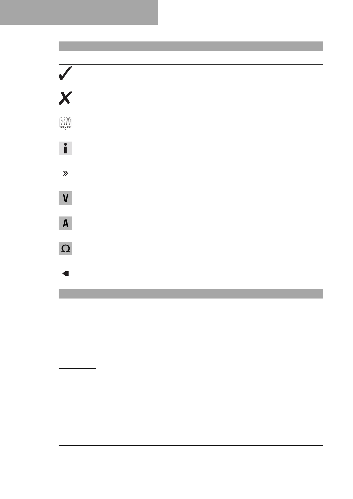
The meaning of specific symbols is described below.
Indicates an expected reaction (e.g. of a work step or a function).
Indicates an unexpected reaction (e.g. of a work step or a function).
Indicates a page reference (more information is provided on the specified page).
Indicates information with more details or tips.
Indicates the result of a testing step.
Indicates a voltage measurement.
Indicates a current measurement.
Indicates a resistance measurement.
Indicates the end of an activity including potential rework.
1.2 Formats used
The typographical formats used in this document are explained below.
Proprietary name Indicates a proprietary name.
®
Name
Brand™ Indicates a brand available on the open market.
Underlined terms Refer to technical details of the vehicle or indicate technical terms, which
Indicates a protected name.
are explained in the glossary.
2
Page 5
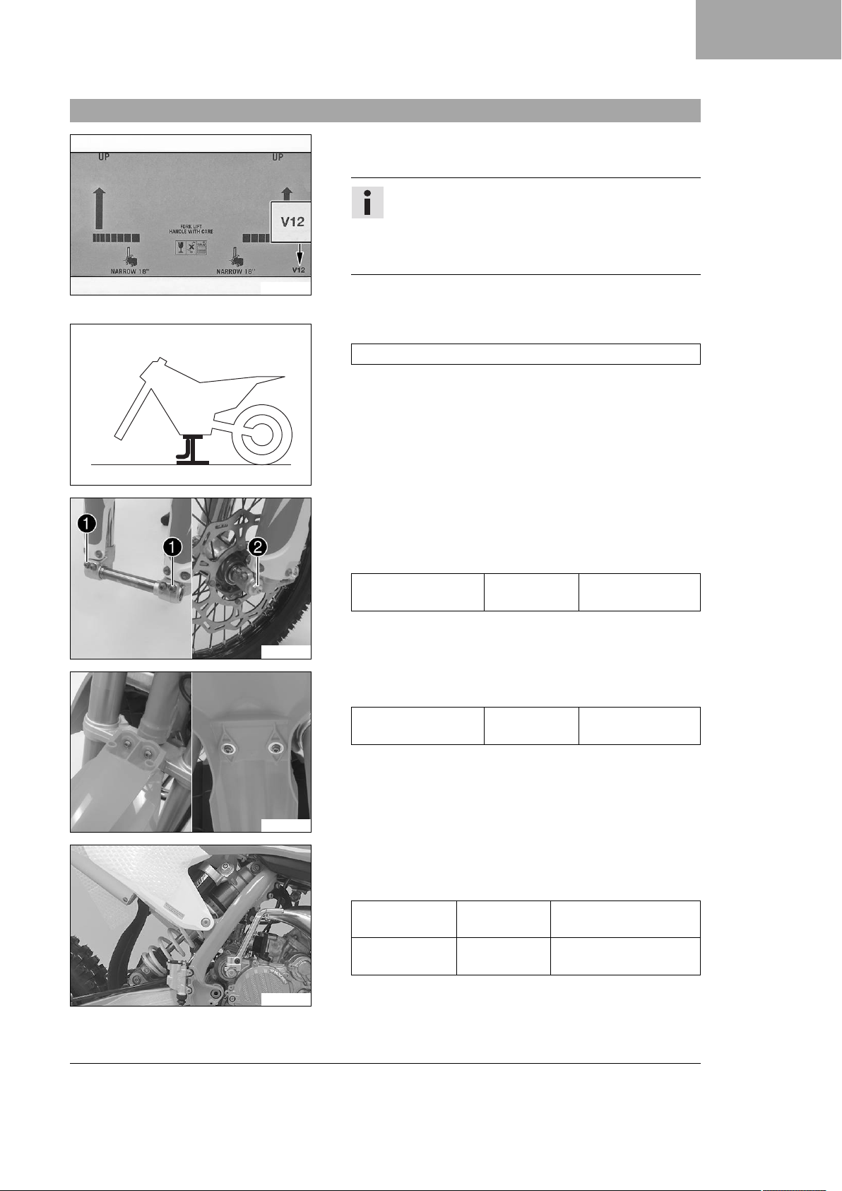
2.1 Unpacking and setting up the vehicle
– Open the box.
– Remove the cable tie and wooden frame.
2 SETUP
Info
An assistant prevents the motorcycle from falling over.
To avoid damaging the motorcycle during the setup,
leave the protective film on the vehicle until you have
finished.
E00850-10
402050-01
V01038-10
– Remove the separate enclosure and unpack it. Check that the
scope of supply is complete using the enclosed packing list.
– Have a lift stand available.
Lift stand (78929955100)
– Together with an assistant, take the vehicle off the pallet.
– Position the vehicle on a lift stand.
– Check the vehicle for transport damage.
–
Loosen screws1and remove wheel spindle. Lift the front
wheel into the fork, position it, and insert the wheel spindle.
–
Mount and tighten the screw of the wheel spindle2.
Guideline
Screw, front wheel
M20x1.5 35 Nm (25.8 lbf ft)
spindle
– Position the fender. Mount and tighten the screws.
Guideline
Remaining screws,
M6 10 Nm (7.4 lbf ft)
chassis
V01039-01
V01040-01
– Unpack the shock absorber.
– Position the shock absorber. Mount and tighten the screws.
Guideline
Screw, top
shock absorber
Screw, bottom
shock absorber
M12 60 Nm (44.3 lbf ft)
Loctite®2701™
M12 60 Nm (44.3 lbf ft)
Loctite®2701™
3
Page 6
2 SETUP
V01041-01
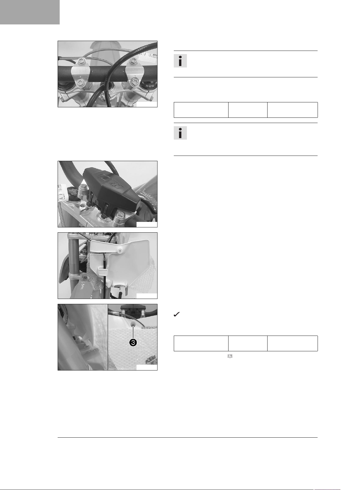
– Position the handlebar.
Info
Make sure the cables and wiring are positioned correctly.
– Position the handlebar clamps. Mount and tighten the screws
evenly.
Guideline
Screw, handlebar
M8 20 Nm (14.8 lbf ft)
clamp
Info
The markings on the handlebar should be at the center
of the handlebar clamps.
Keep the gap widths equal when tightening.
– Position the handlebar cushion and secure with cable ties.
V01042-01
V01043-01
V01044-10
– Attach the start number plate to the brake line.
– Position the start number plate.
The holding lugs engage in the fender.
–
Mount and tighten screw3.
Guideline
Start number plate
M6 4 Nm (3 lbf ft)
screw
– Remove the fuel tank. ( p. 8)
4
Page 7
V01045-10
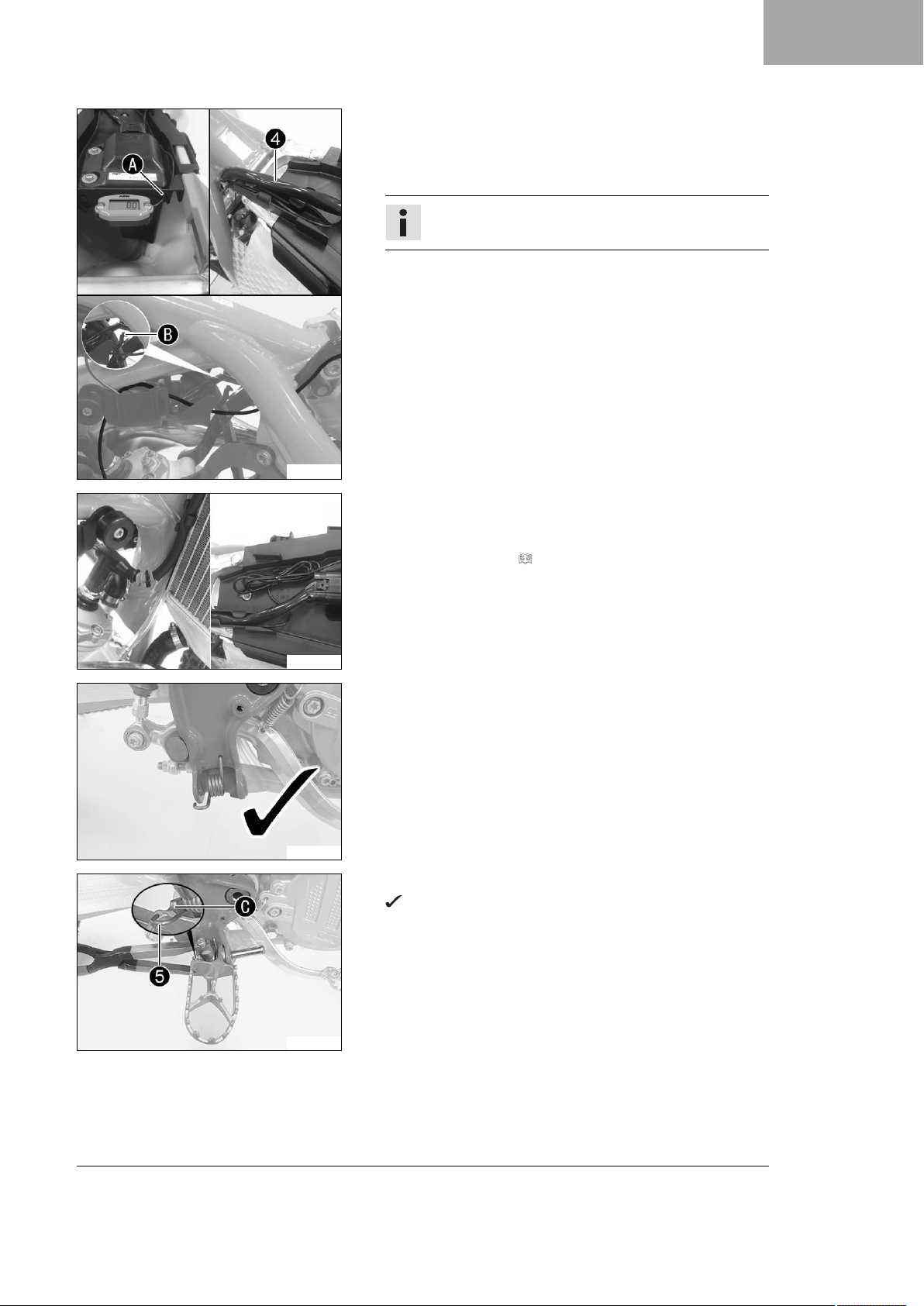
– Mount the service hour counter on the holder.
–
Feed the service hour counter cable through the holeAand
route it under the wiring harness4along the frame to the
ignition wire.
Tip
Detach cable holder in the areaB.
2 SETUP
V01046-01
T01611-10
– Wind the cable for the service hour counter around the ignition
wire, and secure it using cable ties.
– Attach cable holder. Tie excess cable together with a cable tie.
– Install the fuel tank. ( p. 9)
– Position the spring in the hole as shown.
– Position the new footrest and pin.
Spring5engages in areaC.
V01054-10
5
Page 8
2 SETUP
V01055-10
V01056-10
–
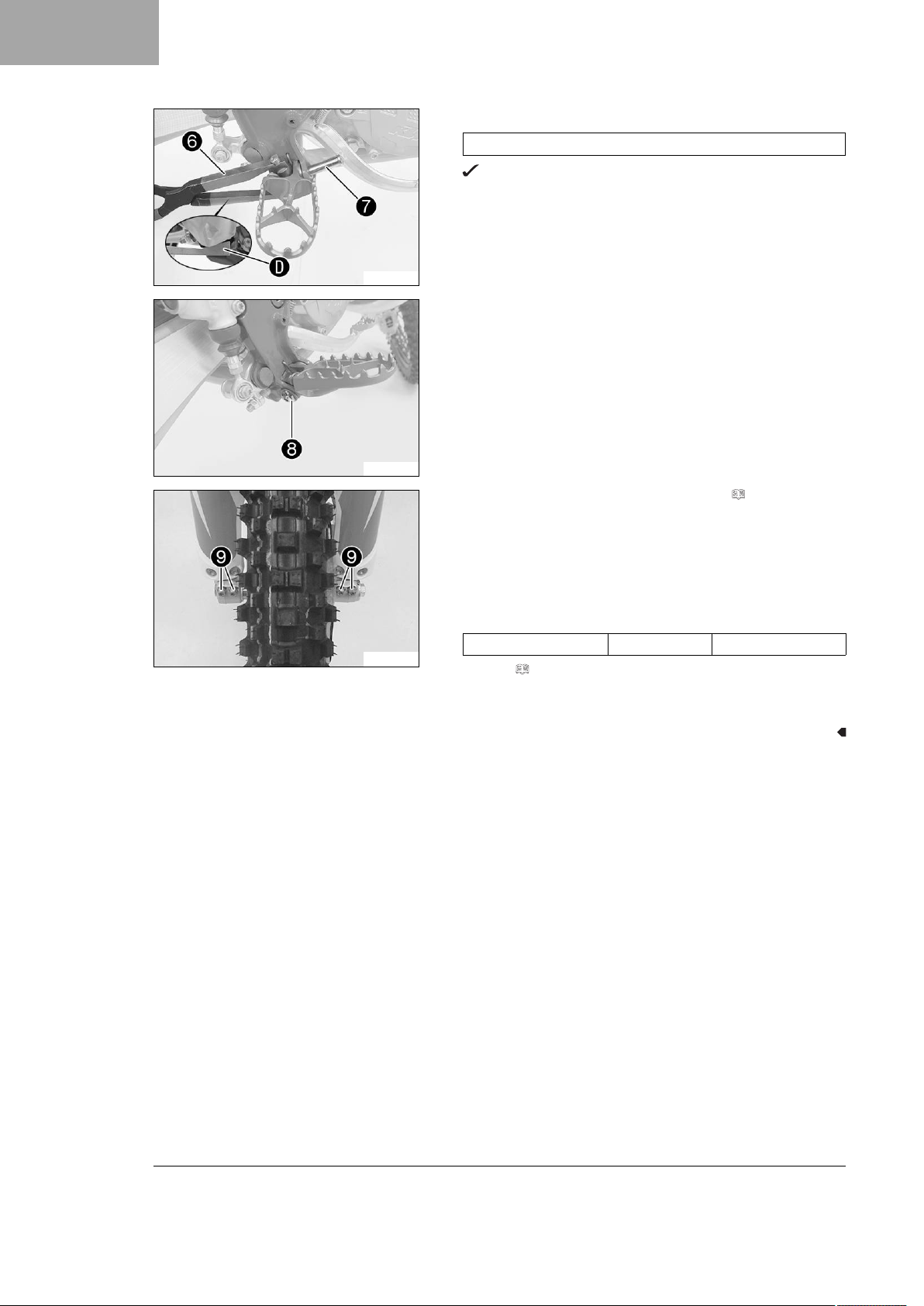
Press the spring with special tool6.
Footrest spring plier (79029083000)
The special tool is applied to areaDon the footrest.
–
Mount pin7.
–
Mount the washer and split pin8.
– Repeat these steps on the opposite side.
– Mount the frame protector.
V01047-10
– Remove the motorcycle from the lift stand. ( p. 7)
– Operate the hand brake lever several times until the brake lin-
ings are seated correctly against the brake disc.
– Activate the front brake and compress the fork a number of
times forcefully to align the fork legs.
–
Tighten screws9.
Guideline
Screw, fork stub M8 15 Nm (11.1 lbf ft)
– Refuel. ( p. 12)
– Prepare the vehicle according to the specifications in the
KTM Dealer.net for handover to the customer.
6
Page 9
3.1 Removing the motorcycle from the lift stand
0011
Note
Danger of damage The parked vehicle can roll away or fall over.
– Park the vehicle on a firm and level surface.
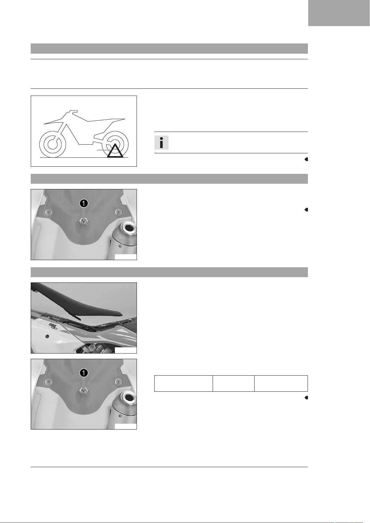
– Remove the motorcycle from the lift stand.
– Remove the lift stand.
–
To park the motorcycle, insert plug-in stand1into the left
side of the wheel spindle.
Info
Remove the plug-in stand before riding.
402001-10
3.2 Removing the seat
–
Remove screw1.
– Raise the rear of the seat, pull the seat back, and lift it off.
3 WORK
3.3 Mounting the seat
V00836-10
V00837-01
V00836-10
– Mount the front of the seat on the collar bushing of the fuel
tank, lower the seat at the rear, and push the seat forward.
– Make sure that the seat is correctly locked in.
–
Mount and tighten screw1of the seat fixing.
Guideline
Remaining screws,
chassis
M6 10 Nm (7.4 lbf ft)
7
Page 10
3 WORK
3.4 Removing the fuel tank
Danger
Fire hazard Fuel is highly flammable.
The fuel in the fuel tank expands when warm and can escape if overfilled.
– Do not refuel the vehicle in the vicinity of open flames or lit cigarettes.
– Switch off the engine for refueling.
– Make sure that no fuel is spilled; particularly not on hot parts of the vehicle.
– If any fuel is spilled, wipe it off immediately.
– Observe the specifications for refueling.
Warning
Danger of poisoning Fuel is poisonous and a health hazard.
– Avoid skin, eye and clothing contact with fuel.
– Immediately consult a doctor if you swallow fuel.
– Do not inhale fuel vapors.
– In case of skin contact, rinse the affected area with plenty of water.
– Rinse the eyes thoroughly with water, and consult a doctor in case of fuel contact with the eyes.
– Change your clothing in case of fuel spills on them.
– Keep fuels correctly in a suitable canister, and out of the reach of children.
V00842-10
V00843-10
Preparatory work
– Remove the seat. ( p. 7)
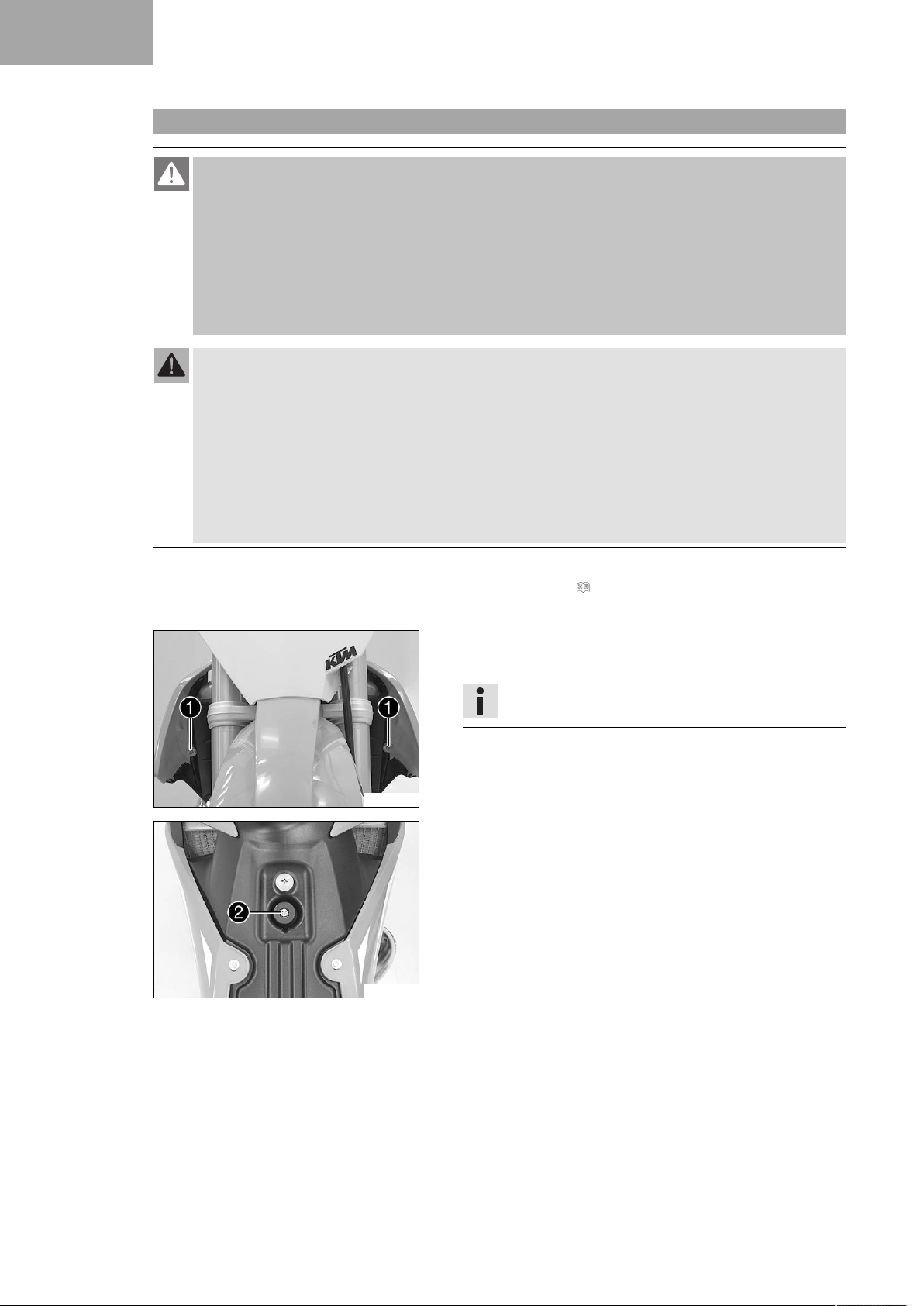
– Turn the tap handle of the fuel tap to the OFF position.
Main work
– Pull off the fuel hose.
Info
Remaining fuel may flow out of the fuel hose.
–
Remove screws1.
–
Remove screw2with the rubber bushing.
– Remove the hose from the fuel tank breather.
8
Page 11
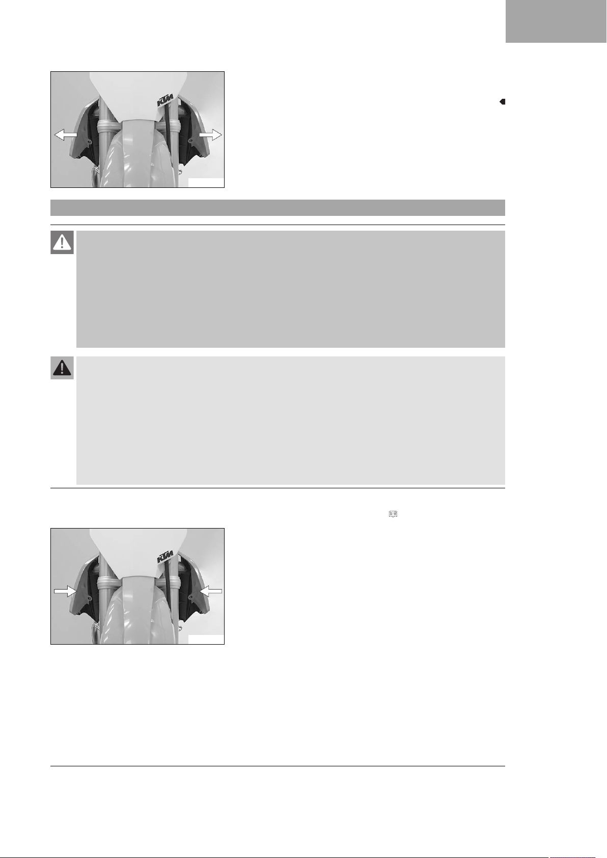
– Pull both spoilers off laterally from the radiator bracket and lift
off the fuel tank.
V00844-10
3.5 Installing the fuel tank
Danger
Fire hazard Fuel is highly flammable.
The fuel in the fuel tank expands when warm and can escape if overfilled.
– Do not refuel the vehicle in the vicinity of open flames or lit cigarettes.
– Switch off the engine for refueling.
– Make sure that no fuel is spilled; particularly not on hot parts of the vehicle.
– If any fuel is spilled, wipe it off immediately.
– Observe the specifications for refueling.
3 WORK
Warning
Danger of poisoning Fuel is poisonous and a health hazard.
– Avoid skin, eye and clothing contact with fuel.
– Immediately consult a doctor if you swallow fuel.
– Do not inhale fuel vapors.
– In case of skin contact, rinse the affected area with plenty of water.
– Rinse the eyes thoroughly with water, and consult a doctor in case of fuel contact with the eyes.
– Change your clothing in case of fuel spills on them.
– Keep fuels correctly in a suitable canister, and out of the reach of children.
Main work
– Check the throttle cable routing. ( p. 10)
– Position the fuel tank and fit the two spoilers to the sides of
the radiator bracket.
– Make sure that no cables or throttle cables are trapped or dam-
aged.
V00844-11
9
Page 12
3 WORK
V00843-11
V00842-11
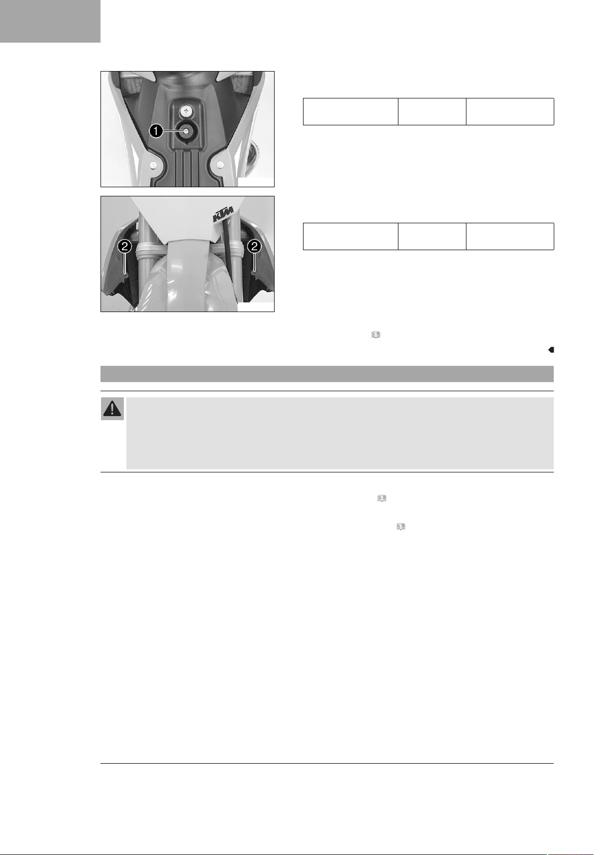
–
Mount and tighten screw1with the rubber bushing.
Guideline
Remaining screws,
chassis
–
Mount and tighten screws2.
Guideline
Remaining screws,
chassis
– Mount fuel hose.
– Position the fuel tank breather in the steering stem.
M6 10 Nm (7.4 lbf ft)
M6 10 Nm (7.4 lbf ft)
Finishing work
– Mount the seat. ( p. 7)
3.6 Checking the throttle cable routing
Warning
Danger of accidents The throttle cable may slip out of the guide if routed incorrectly.
The throttle slide will then no longer be closed and the speed can no longer be controlled.
– Make sure that the throttle cable routing and the play in throttle cable complies with the specifica-
tion.
Preparatory work
– Remove the seat. ( p. 7)
– Turn the tap handle of the fuel tap to the OFF position.
– Remove the fuel tank. ( p. 8)
10
Page 13
V00847-01
3 WORK
Main work
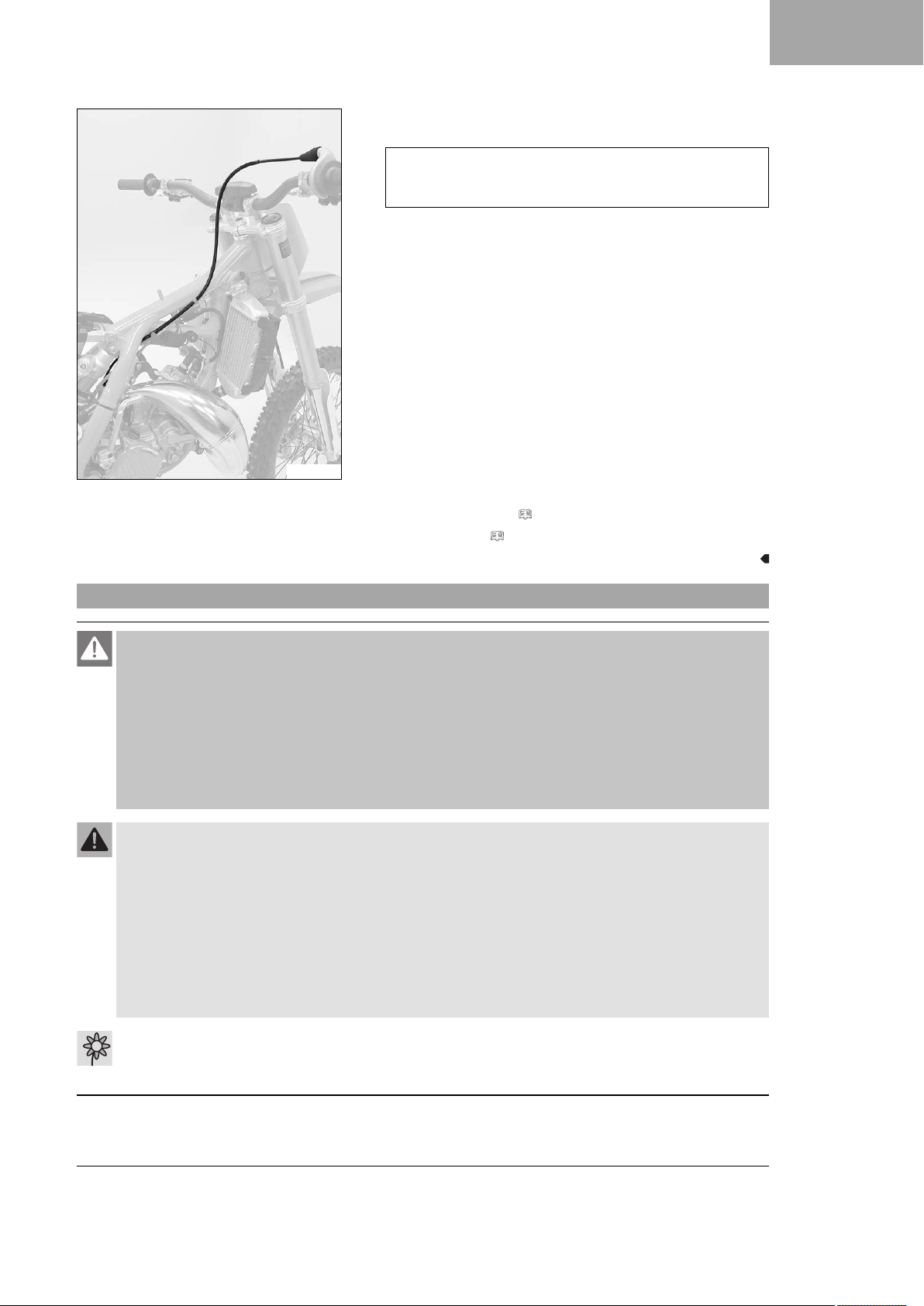
– Check the throttle cable routing.
The throttle cable must be routed along the back of the
handlebar, to the right of the frame, above the fuel tank
bracket, and to the carburetor.
» If the throttle cable is not routed as specified:
– Correct the throttle cable routing.
Finishing work
– Install the fuel tank. ( p. 9)
– Mount the seat. ( p. 7)
3.7 Opening the filler cap
Danger
Fire hazard Fuel is highly flammable.
The fuel in the fuel tank expands when warm and can escape if overfilled.
– Do not refuel the vehicle in the vicinity of open flames or lit cigarettes.
– Switch off the engine for refueling.
– Make sure that no fuel is spilled; particularly not on hot parts of the vehicle.
– If any fuel is spilled, wipe it off immediately.
– Observe the specifications for refueling.
Warning
Danger of poisoning Fuel is poisonous and a health hazard.
– Avoid skin, eye and clothing contact with fuel.
– Immediately consult a doctor if you swallow fuel.
– Do not inhale fuel vapors.
– In case of skin contact, rinse the affected area with plenty of water.
– Rinse the eyes thoroughly with water, and consult a doctor in case of fuel contact with the eyes.
– Change your clothing in case of fuel spills on them.
– Keep fuels correctly in a suitable canister, and out of the reach of children.
Warning
Environmental hazard Improper handling of fuel is a danger to the environment.
– Do not allow fuel to enter the groundwater, the soil, or the sewage system.
11
Page 14
3 WORK
3.8 Closing the filler cap
V00813-10
–
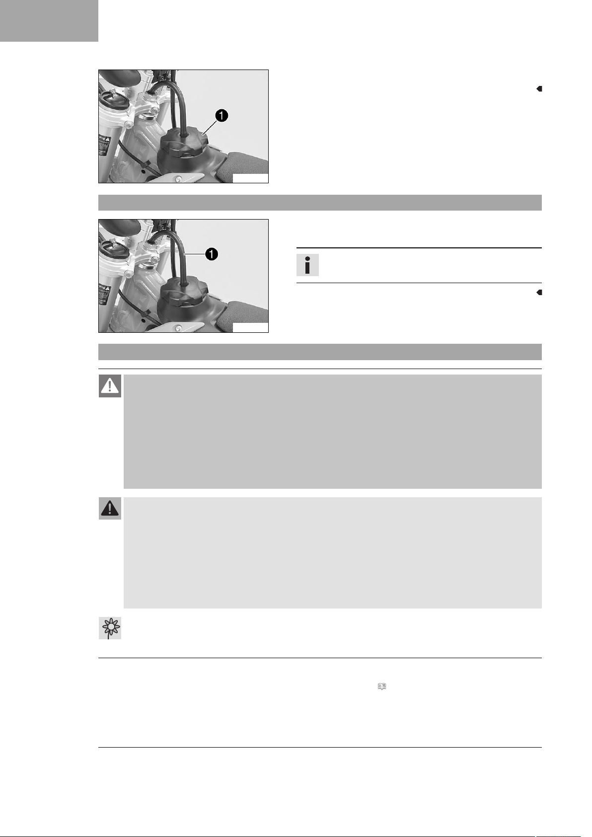
Turn filler cap1counterclockwise and lift it off.
– Mount filler cap and turn it clockwise until the fuel tank is
tightly closed.
Info
Run fuel tank breather hose1without kinks.
V00813-11
3.9 Refueling
Danger
Fire hazard Fuel is highly flammable.
The fuel in the fuel tank expands when warm and can escape if overfilled.
– Do not refuel the vehicle in the vicinity of open flames or lit cigarettes.
– Switch off the engine for refueling.
– Make sure that no fuel is spilled; particularly not on hot parts of the vehicle.
– If any fuel is spilled, wipe it off immediately.
– Observe the specifications for refueling.
Warning
Danger of poisoning Fuel is poisonous and a health hazard.
– Avoid skin, eye and clothing contact with fuel.
– Immediately consult a doctor if you swallow fuel.
– Do not inhale fuel vapors.
– In case of skin contact, rinse the affected area with plenty of water.
– Rinse the eyes thoroughly with water, and consult a doctor in case of fuel contact with the eyes.
– Change your clothing in case of fuel spills on them.
Warning
Environmental hazard Improper handling of fuel is a danger to the environment.
– Do not allow fuel to enter the groundwater, the soil, or the sewage system.
– Switch off the engine.
– Open the filler cap. ( p. 11)
12
Page 15
AA
–
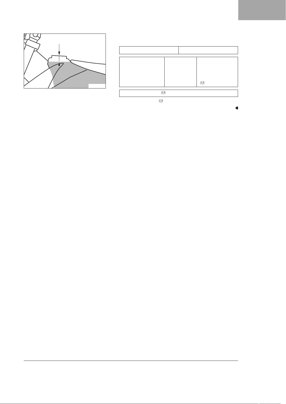
Fill the fuel tank with fuel up to measurementA.
Guideline
Measurement of
A
35 mm (1.38 in)
3 WORK
401522-10
Fuel tank capacity,
approx.
Engine oil, 2-stroke ( p. 16)
– Close the filler cap. ( p. 12)
5.2 l
(1.37 US gal)
Super unleaded
(98 octane) mixed
with 2-stroke
engine oil (1:40)
( p. 16)
13
Page 16
4 TECHNICAL DATA
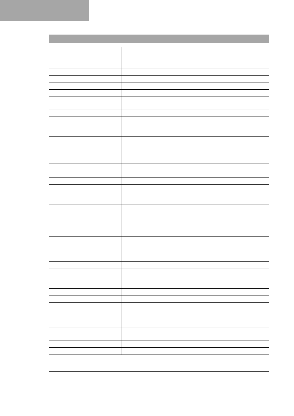
4.1 Chassis tightening torques
Spoke nipple M4.5 5 Nm (3.7 lbf ft)
Screw, main silencer M5 7 Nm (5.2 lbf ft)
Pin, front brake M6 8 Nm (5.9 lbf ft)
Pin, rear brake M6 4 Nm (3 lbf ft)
Remaining nuts, chassis M6 10 Nm (7.4 lbf ft)
Remaining screws, chassis M6 10 Nm (7.4 lbf ft)
Screw for throttle grip M6 5 Nm (3.7 lbf ft)
Screw, ball joint of push rod on
foot brake cylinder
Screw, foot brake cylinder M6 10 Nm (7.4 lbf ft)
Screw, front brake disc M6 14 Nm (10.3 lbf ft)
Screw, front fender M6 6 Nm (4.4 lbf ft)
Screw, rear brake disc M6 14 Nm (10.3 lbf ft)
Start number plate screw M6 4 Nm (3 lbf ft)
Nut, rim lock M8 10 Nm (7.4 lbf ft)
Remaining nuts, chassis M8 25 Nm (18.4 lbf ft)
Remaining screws, chassis M8 25 Nm (18.4 lbf ft)
Screw, bottom triple clamp M8 15 Nm (11.1 lbf ft)
Screw, engine brace M8 25 Nm (18.4 lbf ft)
Screw, fork stub M8 15 Nm (11.1 lbf ft)
Screw, front brake caliper M8 25 Nm (18.4 lbf ft)
Screw, handlebar clamp M8 20 Nm (14.8 lbf ft)
Screw, rear brake caliper M8 18 Nm (13.3 lbf ft)
Screw, rear sprocket M8 35 Nm (25.8 lbf ft)
Screw, subframe M8 35 Nm (25.8 lbf ft)
Screw, top triple clamp M8 20 Nm (14.8 lbf ft)
Engine carrying screw M10 45 Nm (33.2 lbf ft)
Nut, foot brake lever M10 45 Nm (33.2 lbf ft)
Remaining nuts, chassis M10 45 Nm (33.2 lbf ft)
Remaining screws, chassis M10 45 Nm (33.2 lbf ft)
Screw, handlebar support M10 40 Nm (29.5 lbf ft)
Screw, bottom shock absorber M12 60 Nm (44.3 lbf ft)
Screw, top shock absorber M12 60 Nm (44.3 lbf ft)
Nut, seat fixing M12x1 20 Nm (14.8 lbf ft)
Nut, swingarm pivot M14x1.5 75 Nm (55.3 lbf ft)
M6 10 Nm (7.4 lbf ft)
Loctite®243™
Loctite®243™
Loctite®243™
Loctite®2701™
Loctite®243™
Loctite®243™
Loctite®2701™
Loctite®2701™
Loctite®243™
Loctite®243™
Loctite®2701™
Loctite®2701™
14
Page 17
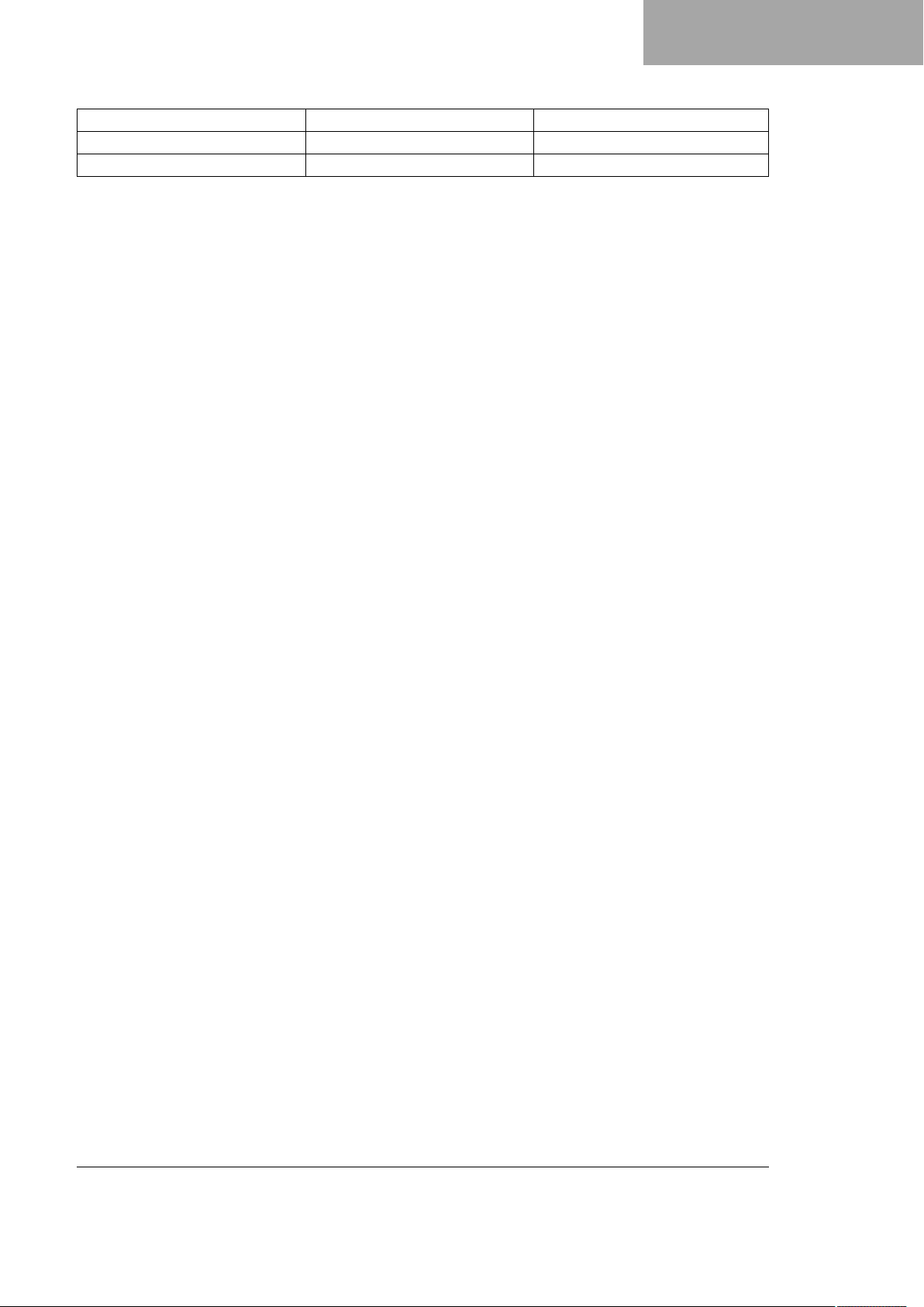
Nut, rear wheel spindle M20x1.5 80 Nm (59 lbf ft)
Nut, steering stem M20x1.5 10 Nm (7.4 lbf ft)
Screw, front wheel spindle M20x1.5 35 Nm (25.8 lbf ft)
4 TECHNICAL DATA
15
Page 18
5 SUBSTANCES
Engine oil, 2-stroke
Standard/classification
– JASO FD ( p. 17)
Guideline
– Only use high grade 2-stroke engine oil of a reputable brand.
Fully synthetic
Recommended supplier
®
Motorex
– Cross Power 2T
Super unleaded (ROZ 98 / RON 98 / PON 94)
Standard/classification
– DIN EN 228 (ROZ 98 / RON 98 / PON 94)
Super unleaded (98 octane) mixed with 2-stroke engine oil (1:40)
Standard/classification
– DIN EN 228
– JASO FD ( p. 17) (1:40)
Mixture ratio
1:40 Engine oil, 2-stroke ( p. 16)
Super unleaded (ROZ 98 / RON 98 / PON 94) ( p. 16)
Recommended supplier
®
Motorex
– Cross Power 2T
16
Page 19

6 STANDARDS
JASO FD
JASO FD is a classification for a 2-stroke engine oil that was specifically developed for the extreme demands of
racing. Thanks to first rate synthetic esters and specially designed additives, superb combustion is achieved even
under extreme operating conditions.
17
Page 20
*3213739en*
3213739en
06/2017
KTM Sportmotorcycle GmbH
5230 Mattighofen/Austria
http://www.ktm.com
Photo: Mitterbauer/KTM
 Loading...