

Ktm 200 EXC EU 2012 User Manual

OWNER'S MANUAL 2012
125 EXC EU
125 EXC SIX DAYS EU
200 EXC EU
200 EXC AUS
200 XC‑W USA
250 EXC EU
250 EXC AUS
250 EXC SIX DAYS EU
250 XC‑W USA
300 EXC EU
300 EXC AUS
300 EXC SIX DAYS EU
300 XC‑W USA
Art. no. 3211718en

DEAR KTM CUSTOMER 1
DEARKTM CUSTOMER
Congratulations on your decision to purchase a KTM motorcycle. You are now the owner of a state-of-the-art sports motorcycle that will
give you enormous pleasure if you service and maintain it accordingly.
We wish you a lot of enjoyment in riding this vehicle.
Enter the serial numbers of your vehicle below.
Chassis number ( p. 10) Dealer's stamp
Engine number ( p. 11)
Key number (All EXC models) ( p. 10)
The owner's manual corresponded to the latest state of this series at the time of printing. Slight deviations resulting from continuing
development and design can, however, not be completely excluded.
All specifications are non-binding. KTM Sportmotorcycle AG specifically reserves the right to modify or delete technical specifications, prices, colors, forms, materials, services, designs, equipment, etc., without prior notice and without specifying reasons, to adapt
these to local conditions, as well as to stop production of a particular model without prior notice. KTM accepts no liability for delivery
options, deviations from illustrations and descriptions, as well as misprints and other errors. The models portrayed partly contain special equipment that does not belong to the regular scope of delivery.
© 2011 KTM-Sportmotorcycle AG, Mattighofen Austria
All rights reserved
Reproduction, even in part, as well as copying of all kinds, is permitted only with the express written permission of the copyright
owner.
ISO 9001(12 100 6061)
According to the international quality management standard ISO 9001, KTM uses quality assurance processes that lead
to the maximum possible quality of the products.
Issued by: TÜV Management Service
KTM-Sportmotorcycle AG
5230 Mattighofen, Austria

TABLE OF CONTENTS 2
TABLEOF CONTENTS
MEANS OF REPRESENTATION ............................................ 5
IMPORTANT INFORMATION ................................................ 6
VIEW OF VEHICLE............................................................... 8
View of vehicle, front left (example)................................... 8
View of vehicle, rear right (example) .................................. 9
SERIAL NUMBERS............................................................ 10
Chassis number............................................................. 10
Type label..................................................................... 10
Key number (All EXC models) ......................................... 10
Engine number.............................................................. 11
Fork part number........................................................... 11
Shock absorber part number ........................................... 11
CONTROLS....................................................................... 12
Clutch lever .................................................................. 12
Hand brake lever ........................................................... 12
Throttle grip.................................................................. 12
Kill switch (All EXC models) ........................................... 12
Short circuit button (XC-W) ............................................ 13
Light switch (All EXC models) ......................................... 13
Turn signal switch (All EXC models) ................................ 13
Horn button (All EXC models) ......................................... 13
Emergency OFF switch (200 EXC AUS) ........................... 13
Emergency OFF switch (250/300 EXC AUS) .................... 14
Electric starter button (250/300 EXC EU,
EXC SIX DAYS, 250/300 XC‑W) ...................................... 14
Electric starter button (250/300 EXC AUS)...................... 14
Light switch (XC-W) ....................................................... 14
Overview of indicator lamps (All EXC models)................... 14
Speedometer................................................................. 15
Speedometer activation and test ..................................... 15
Tripmaster switch .......................................................... 15
Setting kilometers or miles ............................................. 15
Setting the clock ........................................................... 16
Adjusting the speedometer functions............................... 16
Querying lap time .......................................................... 17
Display mode SPEED (speed) ......................................... 17
Display mode SPEED/H (operating hours) ........................ 17
Display mode SPEED/CLK (clock) ................................... 18
Display mode SPEED/LAP (lap time) ............................... 18
Display mode SPEED/ODO (odometer) ............................. 18
Display mode SPEED/TR1 (trip master 1) ........................ 18
Display mode SPEED/TR2 (trip master 2) ........................ 19
Display mode SPEED/A1 (average speed 1)...................... 19
Display mode SPEED/A2 (average speed 2)...................... 19
Display mode SPEED/S1 (stop watch 1) .......................... 20
Display mode SPEED/S2 (stop watch 2) .......................... 20
Fuel tap........................................................................ 21
Opening the filler cap .................................................... 21
Closing the filler cap...................................................... 22
Shift lever..................................................................... 22
Kickstarter.................................................................... 22
Foot brake lever............................................................. 23
Side stand .................................................................... 23
Steering lock (All EXC models)........................................ 23
Locking the steering (All EXC models) ............................. 23
Unlocking the steering (All EXC models) .......................... 24
PREPARING FOR USE ....................................................... 25
Advice on first use ......................................................... 25
Running in the engine.................................................... 26
Preparing the vehicle for difficult operating conditions...... 26
Preparations for riding on dry sand.................................. 27
Preparations for riding on wet sand ................................. 27
Preparations for riding on wet and muddy surfaces ........... 28
Preparations for riding at high temperatures and low
speeds.......................................................................... 28
Preparing for rides at low temperatures or in snow ............ 29
RIDING INSTRUCTIONS .................................................... 30
Checks and maintenance work when preparing for use ...... 30
Starting ........................................................................ 30
Start off........................................................................ 31
Shifting, riding.............................................................. 31
Braking ........................................................................ 31
Stopping, parking .......................................................... 32
Refueling...................................................................... 32
SERVICE SCHEDULE......................................................... 34
Service schedule ........................................................... 34
Maintenance work (as an additional order) ....................... 35
TUNING THE CHASSIS...................................................... 36
Checking the basic chassis setting with the rider's
weight .......................................................................... 36
Compression damping of shock absorber.......................... 36
Adjusting the high-speed compression damping of the
shock absorber .............................................................. 36
Adjusting the low-speed compression damping of the
shock absorber .............................................................. 37
Adjusting the rebound damping of the shock absorber....... 37
Measuring the sag of the unloaded rear wheel .................. 38
Checking the static sag of the shock absorber .................. 38
Checking the riding sag of the shock absorber .................. 39
Adjusting the spring preload of the shock absorber x ...... 39
Adjusting the riding sag x............................................. 40
Checking the basic setting of the fork.............................. 40
Adjusting the compression damping of the fork ................ 41
Adjusting the rebound damping of the fork....................... 41
Adjusting the spring preload of the fork ........................... 42
Handlebar position ........................................................ 42
Adjusting the handlebar position x................................ 42
SERVICE WORK ON THE CHASSIS ..................................... 44
Raising the motorcycle with the lift stand ........................ 44
Removing the motorcycle from the lift stand .................... 44
Bleeding the fork legs .................................................... 44
Cleaning the dust boots of the fork legs ........................... 45
Loosening the fork protection.......................................... 45
Positioning the fork protection ........................................ 46
Removing the fork legs x.............................................. 46
Installing the fork legs x............................................... 46
Removing the fork protector x....................................... 47
Installing the fork protector x ....................................... 48
Removing the lower triple clamp x (EXC EU/AUS,
XC‑W)........................................................................... 48
Removing the lower triple clamp x (EXC SIX DAYS) ........ 48
Installing the lower triple clamp x (EXC EU/AUS,
XC‑W)........................................................................... 49
Installing the lower triple clamp x (EXC SIX DAYS) ......... 50
Checking the play of the steering head bearing................. 52
Adjusting the play of the steering head bearing x............ 52
Greasing the steering head bearing x............................. 53
Removing the start number plate (XC-W).......................... 53
Installing the start number plate (XC-W) .......................... 53
Removing the front fender .............................................. 54
Installing the front fender............................................... 54
Removing the shock absorber x..................................... 54
Installing the shock absorber x ..................................... 54

TABLE OF CONTENTS 3
Removing the seat ......................................................... 55
Mounting the seat ......................................................... 55
Removing the air filter box lid......................................... 56
Installing the air filter box lid.......................................... 56
Removing the air filter x............................................... 56
Installing the air filter x ............................................... 56
Cleaning the air filter and air filter box x........................ 57
Removing the main silencer............................................ 57
Installing the main silencer ............................................ 58
Changing the glass fiber yarn filling of the main
silencer x ................................................................... 58
Removing the fuel tank x ............................................. 58
Installing the fuel tank x .............................................. 59
Checking the chain for dirt ............................................. 60
Cleaning the chain......................................................... 60
Checking the chain tension ............................................ 61
Checking the chain, rear sprocket, engine sprocket and
chain guide................................................................... 61
Adjusting the chain tension ............................................ 63
Adjusting the chain guide x.......................................... 64
Checking the frame x................................................... 65
Checking the swingarm x ............................................. 65
Checking the throttle cable routing.................................. 65
Checking the rubber grip ................................................ 66
Additionally securing the rubber grip ............................... 66
Adjusting the basic position of the clutch lever................. 66
Checking the fluid level of the hydraulic clutch ................ 67
Changing the hydraulic clutch fluid x ............................ 67
BRAKES........................................................................... 69
Checking free travel of hand brake lever........................... 69
Adjusting the basic position of the hand brake lever
(XC-W).......................................................................... 69
Adjusting free travel of hand brake lever (All EXC
models) ........................................................................ 69
Checking the brake discs................................................ 70
Checking the front brake fluid level ................................. 70
Adding front brake fluid x ............................................ 70
Checking the front brake linings...................................... 71
Changing the front brake linings x................................. 72
Checking the free travel of foot brake lever....................... 73
Adjusting the basic position of the foot brake lever x ...... 73
Checking the rear brake fluid level .................................. 74
Adding brake fluid for the rear brake x .......................... 74
Checking the rear brake linings ....................................... 75
Removing the rear brake linings x ................................. 75
Installing the rear brake linings x.................................. 76
Changing the rear brake linings x.................................. 76
WHEELS, TIRES ............................................................... 78
Removing the front wheel x .......................................... 78
Installing the front wheel x........................................... 78
Removing the rear wheel x ........................................... 79
Installing the rear wheel x ............................................ 79
Checking the tire condition............................................. 80
Checking the tire air pressure ......................................... 81
Checking the spoke tension ............................................ 81
ELECTRICAL SYSTEM ....................................................... 83
Removing the battery x (All 250/300 models) ................ 83
Installing the battery x (All 250/300 models)................. 83
Recharging the battery x (All 250/300 models) .............. 83
Changing the main fuse (All 250/300 models) ................. 84
Removing the headlight mask with the headlight (All EXC
models) ........................................................................ 85
Refitting the headlight mask with the headlight (All EXC
models) ........................................................................ 86
Changing the headlight bulb (All EXC models).................. 86
Checking the headlight setting (All EXC models)............... 87
Adjusting the headlight range (All EXC models) ................ 87
Changing the speedometer battery .................................. 87
COOLING SYSTEM ............................................................ 89
Cooling system .............................................................. 89
Checking the antifreeze and coolant level ........................ 89
Checking the coolant level.............................................. 90
Draining the coolant x.................................................. 90
Refilling with coolant x ................................................ 91
TUNING THE ENGINE ....................................................... 93
Checking the play in the throttle cable............................. 93
Adjusting the play in the throttle cable x ....................... 93
Carburetor .................................................................... 93
Carburetor - adjusting the idle speed x .......................... 94
Emptying the carburetor float chamber x ....................... 95
Checking the basic position of the shift lever.................... 96
Adjusting the basic position of the shift lever x .............. 96
Engine characteristic - auxiliary spring
(All 250/300 models) .................................................... 96
Engine characteristic - adjusting the auxiliary spring x
(All 250/300 models) .................................................... 96
SERVICE WORK ON THE ENGINE ...................................... 98
Checking the gear oil level.............................................. 98
Changing the gear oil x ................................................ 98
Draining the gear oil x ................................................. 99
Refilling with gear oil x ................................................ 99
Adding gear oil x ....................................................... 100
CLEANING, CARE ........................................................... 101
Cleaning the motorcycle ............................................... 101
Checks and maintenance steps for winter operation ........ 102
STORAGE ....................................................................... 103
Storage....................................................................... 103
Preparing for use after storage ...................................... 103
TROUBLESHOOTING....................................................... 104
TECHNICAL DATA - ENGINE ............................................ 106
125 EXC EU, 125 EXC SIX DAYS EU ............................ 106
All 200 models ........................................................... 106
All 250 models ........................................................... 107
All 300 models ........................................................... 107
Capacity - transmission oil............................................ 108
Capacity - coolant........................................................ 108
TECHNICAL DATA - ENGINE TIGHTENING TORQUES ........ 109
All 125/200 models .................................................... 109
All 250/300 models .................................................... 110
TECHNICAL DATA - CARBURETOR................................... 111
125 EXC EU, 125 EXC SIX DAYS EU ............................ 111
200 EXC EU ............................................................... 111
200 EXC AUS ............................................................. 111
200 XC‑W USA ........................................................... 111
250 EXC EU, 250 EXC SIX DAYS EU ............................ 112
250 EXC AUS ............................................................. 112
250 XC‑W USA ........................................................... 112
300 EXC EU, 300 EXC SIX DAYS EU ............................ 112
300 EXC AUS ............................................................. 113
300 XC‑W USA ........................................................... 113
Carburetor configuration (125 EXC EU,
125 EXC SIX DAYS EU) x .......................................... 113

TABLE OF CONTENTS 4
Carburetor configuration (All 200 models) x................. 115
Carburetor configuration (All 250 models) x................. 116
Carburetor configuration (All 300 models) x................. 117
General carburetor configuration x .............................. 118
TECHNICAL DATA - CHASSIS .......................................... 119
Lighting equipment ..................................................... 120
Tires .......................................................................... 120
Capacity - fuel............................................................. 120
TECHNICAL DATA - FORK................................................ 121
All 125/200 models .................................................... 121
All 250/300 models .................................................... 121
TECHNICAL DATA - SHOCK ABSORBER ........................... 123
All 125/200 models .................................................... 123
All 250/300 models .................................................... 123
TECHNICAL DATA - TIGHTENING TORQUES FOR
CHASSIS ........................................................................ 125
SUBSTANCES................................................................. 126
AUXILIARY SUBSTANCES................................................ 128
STANDARDS................................................................... 130
INDEX ............................................................................ 131
MEANS OF REPRESENTATION 5
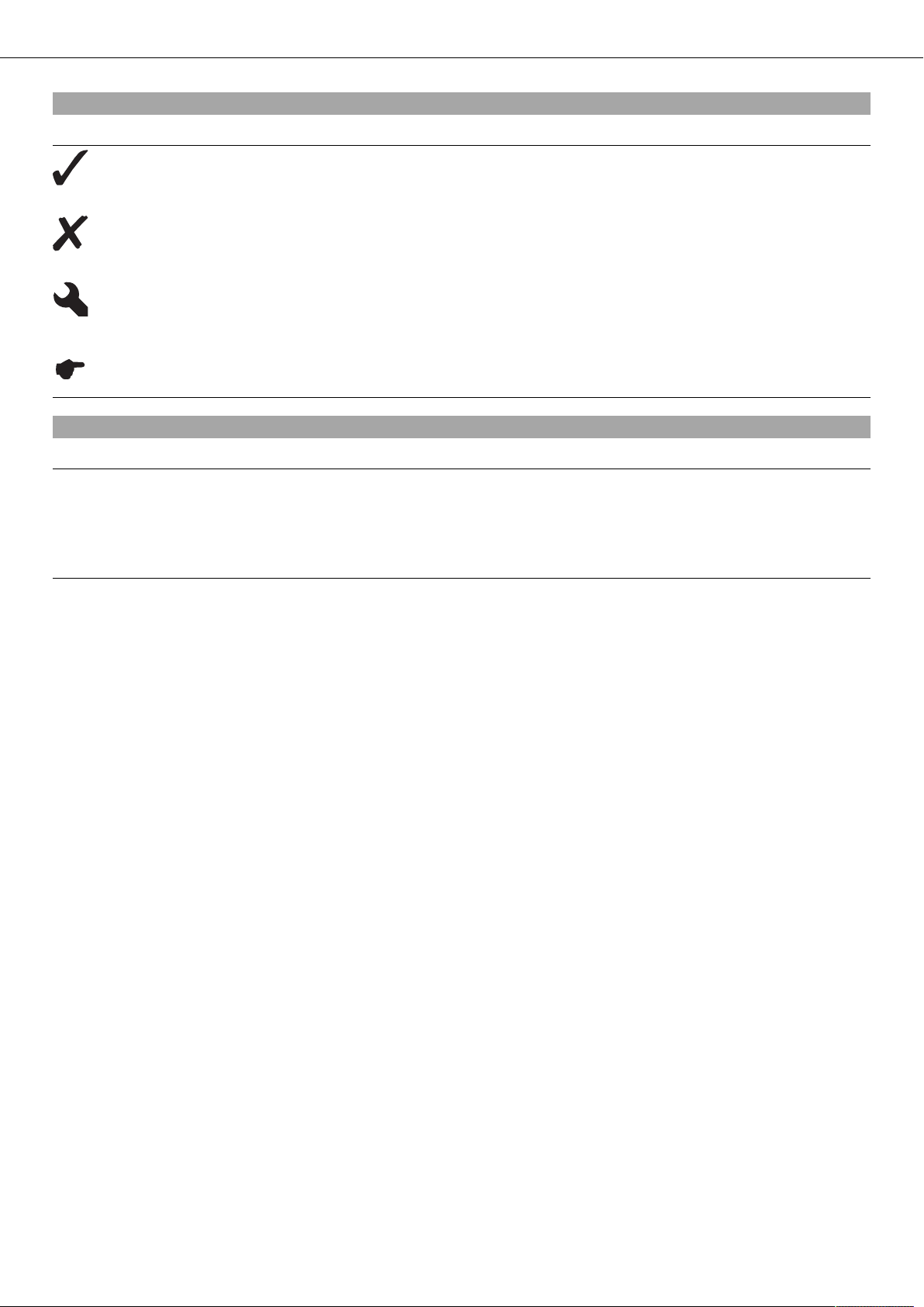
Symbols used
The symbols used are explained below.
Indicates an expected reaction (e.g., to a work step or a function).
Indicates an unexpected reaction (e.g., to a work step or a function).
All work marked with this symbol requires specialist knowledge and technical understanding. In the interest of
your own safety, have these jobs done in an authorized KTM workshop! There, your motorcycle will be serviced
optimally by specially trained experts using the specialist tools required.
Identifies a page reference (more information is provided on the specified page).
Formats used
The typographical and other formats used are explained below.
Specific name Identifies a specific name.
®
Name
Brand™ Identifies a brand available on the open market.
Identifies a protected name.
IMPORTANT INFORMATION 6
Use definition (All EXC models)
KTM sport motorcycles are designed and built to withstand the normal stresses and strains of competitive use. The motorcycles comply with currently valid regulations and categories of the top international motorsport organizations.
Info
The motorcycle is authorized for public road traffic in the homologous (reduced) version only.
In the derestricted version, the motorcycle must be used only on closed off property remote from public road traffic.
The motorcycle is designed for offroad sport endurance competition (Enduro) and not for predominant motocross use.
Use definition (XC-W)
KTM sport motorcycles are designed and built to withstand the normal stresses and strains of competitive use. The motorcycles comply with currently valid regulations and categories of the top international motorsport organizations.
Info
The motorcycle must be used only on closed off property remote from public road traffic.
The motorcycle is designed for offroad sport endurance competition (Enduro) and not for predominant motocross use.
Service
A prerequisite for perfect operation and prevention of wear is that the engine and chassis service, care and adjustment work described
in the owner's manual is properly carried out. Poor adjustment and tuning of the engine and chassis can lead to damage and breakage
of components.
Using the motorcycle in difficult conditions such as on sand or very muddy or wet terrain can lead to above-average wear of components such as the transmission train or the brakes. For this reason, it may be necessary to service or replace worn parts before the
limit specified in the service schedule is reached.
Pay careful attention to the prescribed running-in period and service intervals. If you observe these exactly, you will ensure a much
longer service life for your motorcycle.
Warranty
The work prescribed in the service schedule must be carried out by an authorized KTM workshop only and confirmed in the customer's
service record and in the KTM dealer.net; otherwise, all warranty claims will be void. No warranty claims can be considered for damage
resulting from manipulations and/or alterations to the vehicle.
Fuel, oils, etc.
You should use the fuels, oils and greases according to specifications as listed in the owner's manual.
Spare parts, accessories
For your own safety, only use spare parts and accessory products that have been approved and/or recommended by KTM and have
them installed by an authorized KTM workshop. KTM accepts no liability for other products and any resulting damage or loss.
Certain spare parts and accessories are specified in parentheses in the descriptions. Your KTM dealer will be glad to advise you.
You will find the current KTM PowerParts for your vehicle on the KTM website.
International KTM Website: http://www.ktm.com
Work rules
Special tools are needed for certain tasks. They are not included with the vehicle but can be ordered under the number in parentheses. E.g.: bearing puller (15112017000)
When the vehicle is assembled, non-reusable parts (e.g., self-locking screws and nuts, gaskets, seal rings, O-rings, splints, lock washers) must be replaced with new parts.
Where thread lockers are used on screw connections (e.g., Loctite®), follow the instructions for use from the manufacturer.
After disassembly, clean the parts that are to be reused and check them for damage and wear. Replace damaged or worn parts.
After you complete the repair or maintenance work, check the roadworthiness of the vehicle.
Transport
Note
Danger of damage The parked vehicle may roll away or fall over.
– Always place the vehicle on a firm and even surface.
IMPORTANT INFORMATION 7
Note
Fire hazard Some vehicle components become very hot when the vehicle is operated.
– Do not park the vehicle near flammable or explosive substances. Do not place objects on the vehicle while it is still warm from
being run. Always let the vehicle cool first.
– Switch off the engine.
– Turn handle of the fuel tap to the OFF position.
– Use straps or other suitable devices to secure the motorcycle against accidents or falling over.
Environment
Motorcycling is a wonderful sport and we naturally hope that you can enjoy it to the full. However, it is a potential problem for the
environment and can lead to conflicts with other persons. But if you use your motorcycle responsibly, you can ensure that such problems and conflicts do not have to occur. To protect the future of motorcycle sport, make sure that you use your motorcycle legally, display environmental consciousness, and respect the rights of others.
Notes/warnings
Pay close attention to the notes/warnings.
Info
Various information and warning labels are affixed to the vehicle. Do not remove information/warning labels. If they are missing, you or others may not recognize potential hazards and may therefore be injured.
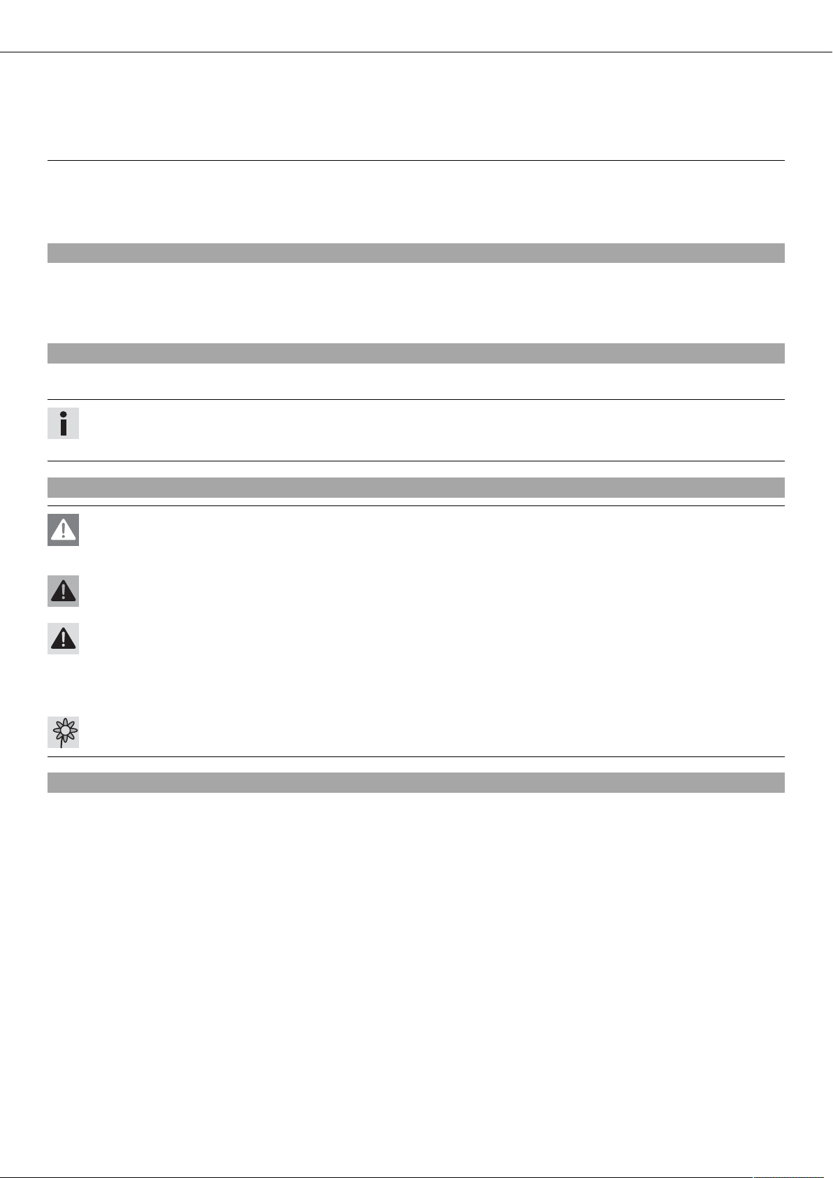
Grades of risks
Danger
Identifies a danger that will immediately and invariably lead to fatal or serious permanent injury if the appropriate measures
are not taken.
Warning
Identifies a danger that is likely to lead to fatal or serious injury if the appropriate measures are not taken.
Caution
Identifies a danger that may lead to minor injuries if the appropriate measures are not taken.
Note
Identifies a danger that will lead to considerable machine and material damage if the appropriate measures are not taken.
Warning
Identifies a danger that will lead to environmental damage if the appropriate measures are not taken.
Owner's manual
– It is important that you read this owner's manual carefully and completely before making your first trip. It contains information and
tips that will assist you in operating and handling your motorcycle properly. Only then will you learn how to adjust the motorcycle
to your own requirements and how to protect yourself from injury. The owner's manual also contains important information on servicing the motorcycle.
– The owner's manual is an important component of the motorcycle and should be handed over to the new owner if the vehicle is
sold.
VIEW OF VEHICLE 8
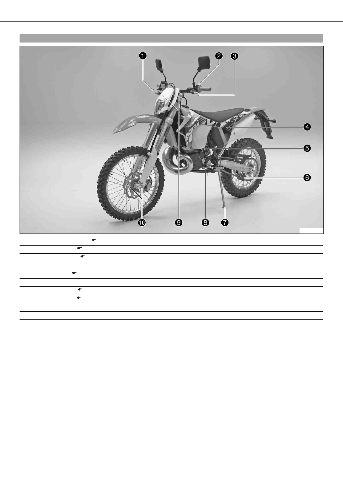
3.1View of vehicle, front left (example)
1 Hand brake lever ( p. 12)
2 Kill switch ( p. 12)
3 Clutch lever ( p. 12)
4 Air filter box lid
5 Fuel tap ( p. 21)
6 Chain guide
7 Side stand ( p. 23)
8 Shift lever ( p. 22)
9 Fork rebound adjustment
10 Fork compression adjustment
B00784-10

VIEW OF VEHICLE 9
3.2View of vehicle, rear right (example)
1 Filler cap
2 Bleeder screw, fork leg
3 Throttle grip ( p. 12)
4 Chassis number ( p. 10)
5 Kickstarter ( p. 22)
6 Foot brake lever ( p. 23)
7 Shock absorber, compression adjustment
8 Level viewer, rear brake fluid
9 Shock absorber, rebound adjustment
B00783-10
SERIAL NUMBERS 10
4.1Chassis number
(XC-W)
The chassis number is stamped on the right side of the steering head.
B00015-10
(All EXC models)
The chassis number is stamped on the right side of the steering head.
303438-10
4.2Type label
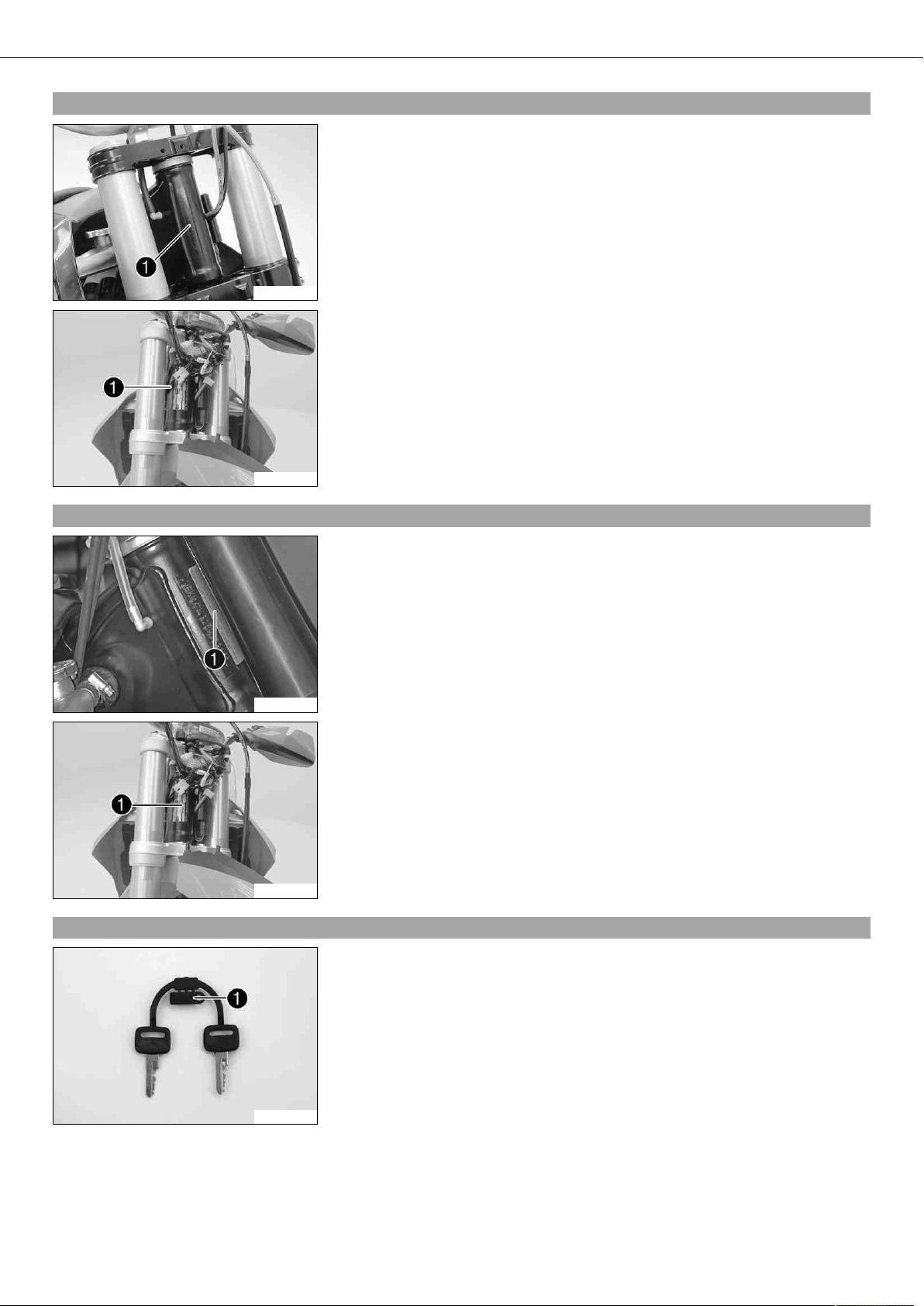
4.3Key number (All EXC models)
(XC-W)
The type label is fixed to the front of the steering head.
400284-10
(All EXC models)
The type label is fixed to the front of the steering head.
303439-10
The key number for the steering lock is stamped onto the key connector.
500125-10
SERIAL NUMBERS 11
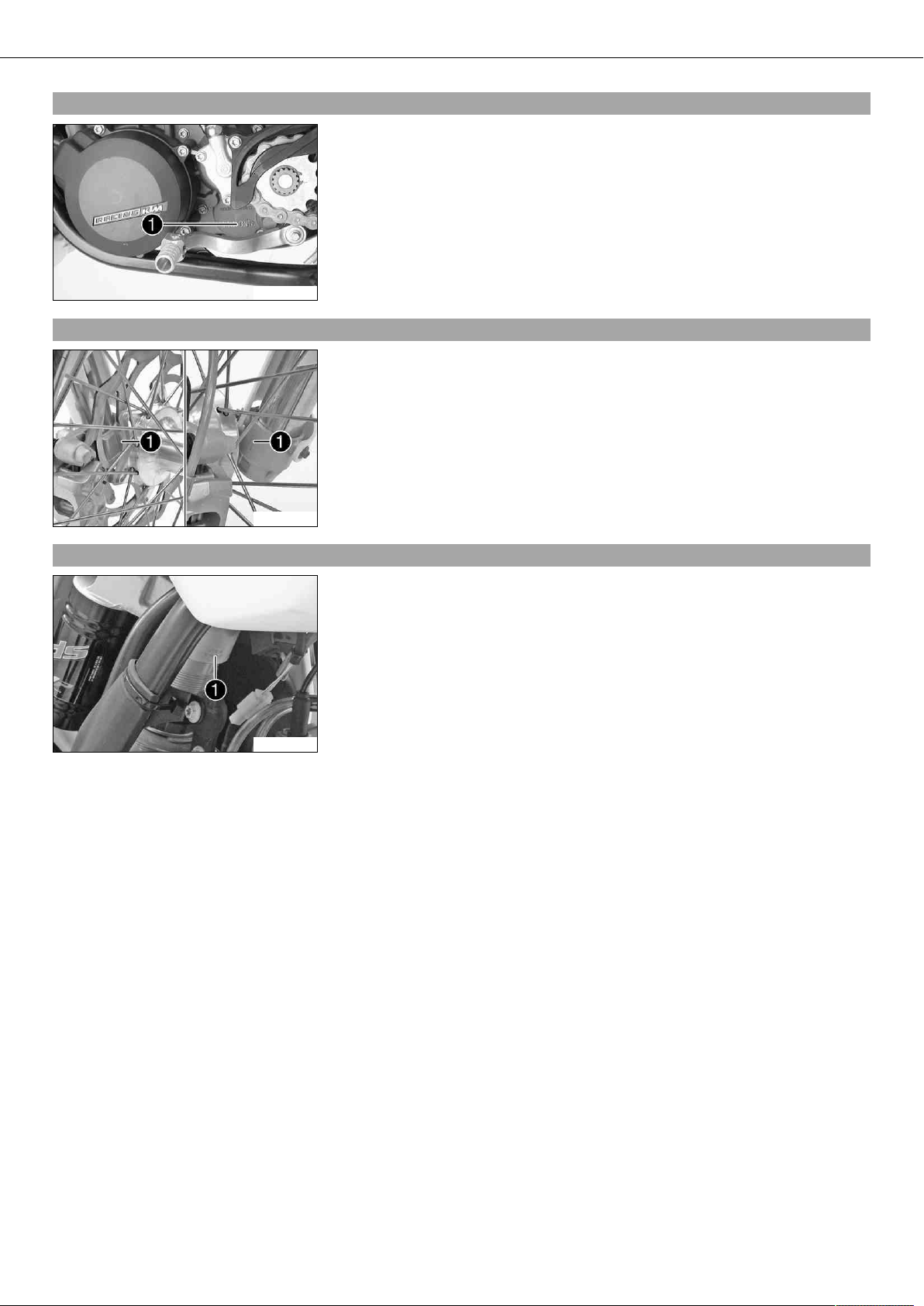
4.4Engine number
The engine number is stamped on the left side of the engine under the engine
sprocket.
B00016-10
4.5Fork part number
The fork part number is stamped on the inner side of the fork stub.
4.6Shock absorber part number
B00265-01
The shock absorber part number is stamped on the top of the shock absorber above
the adjusting ring on the engine side.
B00786-10
CONTROLS 12
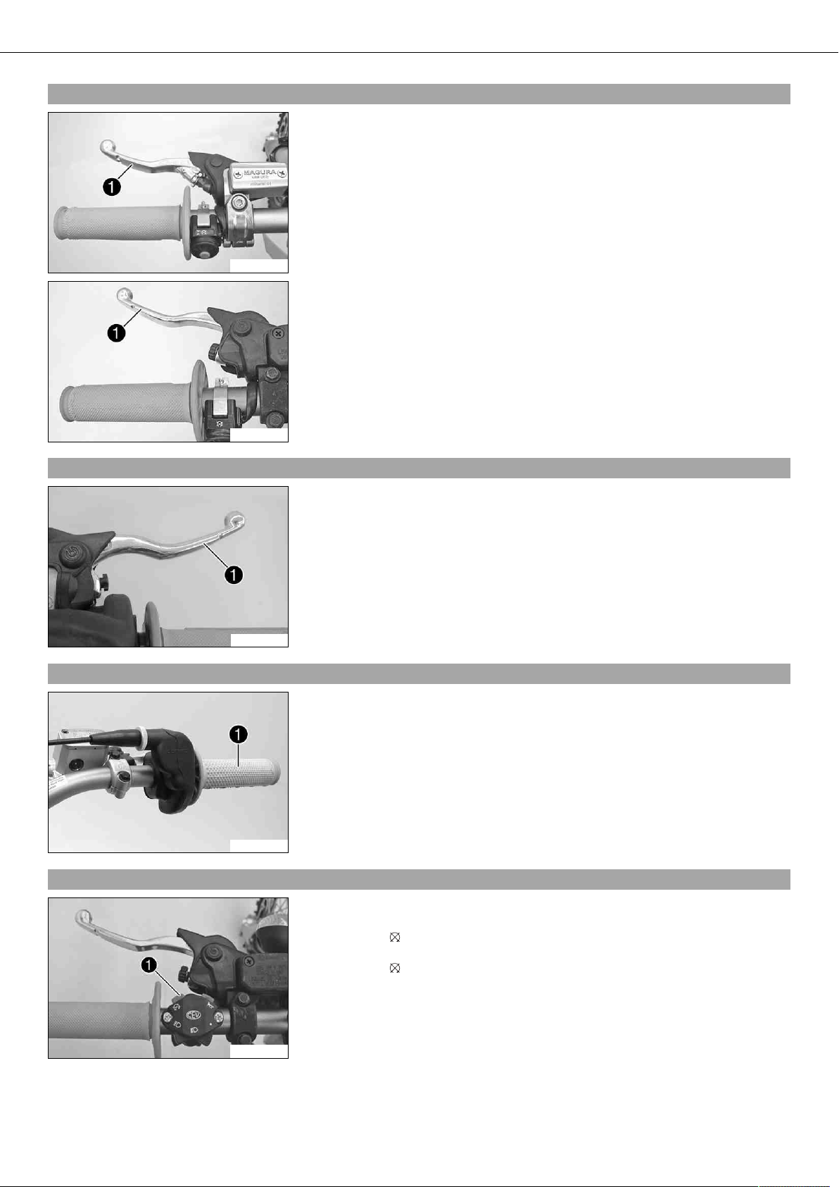
5.1Clutch lever
(All 125/200 models)
The clutch lever is fitted on the left side of the handlebar.
The clutch is hydraulically operated and self-adjusting.
B00001-10
(All 250/300 models)
The clutch lever is fitted on the left side of the handlebar.
The clutch is hydraulically operated and self-adjusting.
B00009-10
5.2Hand brake lever
5.3Throttle grip
Hand brake lever is located on the right side of the handlebar.
The hand brake lever is used to activate the front brake.
400196-10
Throttle grip is fitted on the right side of the handlebar.
B00060-10
5.4Kill switch (All EXC models)
The kill switch is fitted on the left side of the handlebar.
Possible states
• Kill switch in basic position – In this position, the ignition circuit is closed and
the engine can be started.
• Kill switch pressed – In this position, the ignition circuit is interrupted, a running engine stops, and a non-running engine will not start.
B00078-10
CONTROLS 13
5.5Short circuit button (XC-W)
Short circuit button is fitted on the left side of the handlebar.
Possible states
• Short circuit button in basic position – In this position, the ignition circuit is
closed, and the engine can be started.
• Short circuit button pressed – In this position, the ignition circuit is interrupted,
a running engine stops, and a non-running engine will not start.
B00002-10
5.6Light switch (All EXC models)
The light switch is fitted on the left side of the handlebar.
Possible states
Light off – Light switch is turned to the right. In this position, the light
is switched off.
Low beam on – Light switch is in the central position. In this position,
the low beam and tail light are switched on.
High beam on – Light switch is turned to the left. In this position, the
B00082-10
high beam and the tail light are switched on.
5.7Turn signal switch (All EXC models)
101299-10
5.8Horn button (All EXC models)
B00083-10
Turn signal switch is fitted on the left side of the handlebar.
Possible states
Turn signal off – The turn signal switch is in the central position.
Left turn signal, on – The turn signal switch is turned to the left.
Right turn signal, on – The turn signal switch is turned to the right.
The horn button is fitted on the left side of the handlebar.
Possible states
• Horn button in neutral position
• Horn button pressed – The horn is operated in this position.
5.9Emergency OFF switch (200 EXC AUS)
B00087-10
The emergency OFF switch is fitted on the right side of the handlebar.
Possible states
Ignition off – In this position, the ignition circuit is interrupted, a running engine stops, and a non-running engine will not start.
Ignition on – In this position, the ignition circuit is closed, and the
engine can be started.
CONTROLS 14
5.10Emergency OFF switch (250/300 EXC AUS)
The emergency OFF switch is fitted on the right side of the handlebar.
Possible states
Ignition off – In this position, the ignition circuit is interrupted, a running engine stops, and a non-running engine will not start.
Ignition on – In this position, the ignition circuit is closed, and the
engine can be started.
B00079-10
5.11Electric starter button (250/300 EXC EU, EXC SIX DAYS, 250/300 XC‑W)
The electric starter button is fitted on the right side of the handlebar.
Possible states
• Electric starter button in basic position
• Electric starter button pressed – In this position, the electric starter is actuated.
B00080-10
5.12Electric starter button (250/300 EXC AUS)
The electric starter button is fitted on the right side of the handlebar.
Possible states
• Electric starter button in basic position
• Electric starter button pressed – In this position, the electric starter is actuated.
B00081-10
5.13Light switch (XC-W)
Light switch is located to the right of the speedometer.
Possible states
• The light switch has no function when the vehicle is delivered – It can be used to
retrofit the vehicle with a lighting system.
500146-10
5.14Overview of indicator lamps (All EXC models)
Possible states
500147-01
High beam indicator lamp lights up blue – High beam is switched on.
Turn signal indicator lamp flashes green – Turn signal light is switched
on.
CONTROLS 15
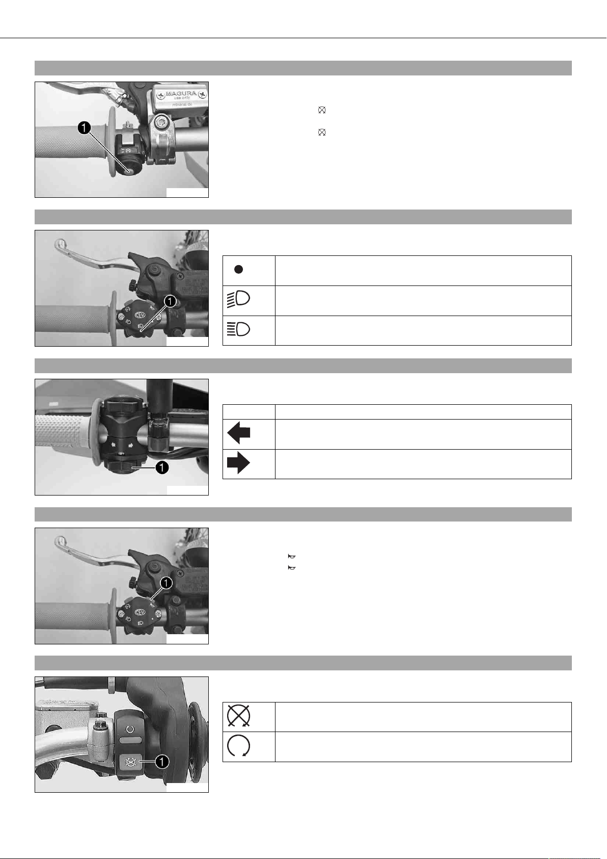
5.15Speedometer
– Press the button to change the display mode or change to one of the Setup
menus.
– Press the button to control different functions.
– Press the button to control different functions.
Info
When the vehicle is delivered, only the SPEED/H and SPEED/ODO display modes
are activated.
400312-01
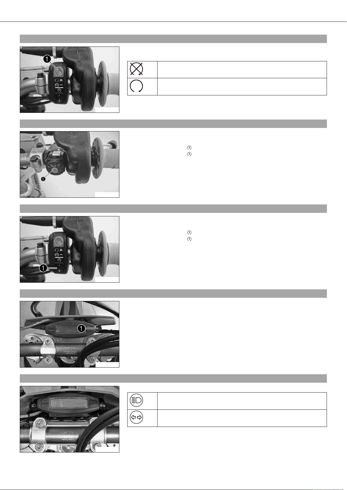
5.16Speedometer activation and test
Activating the speedometer
The speedometer is activated when one of the buttons is pressed or an impulse comes
from the wheel speed sensor.
Display test
For the function test of the display, all display segments light up briefly.
400313-01
WS (wheel size)
After the display function test, the wheel size WS is displayed briefly.
Info
The number 2205 mm equals the circumference of the 21" front wheel with a
series production tire.
The display then changes to the last selected mode.
400314-01
5.17Tripmaster switch
(Option: Tripmaster switch)
You can use the trip master switch to control the functions of the speedometer from the handlebar.
Info
The trip master is an optional accessory.
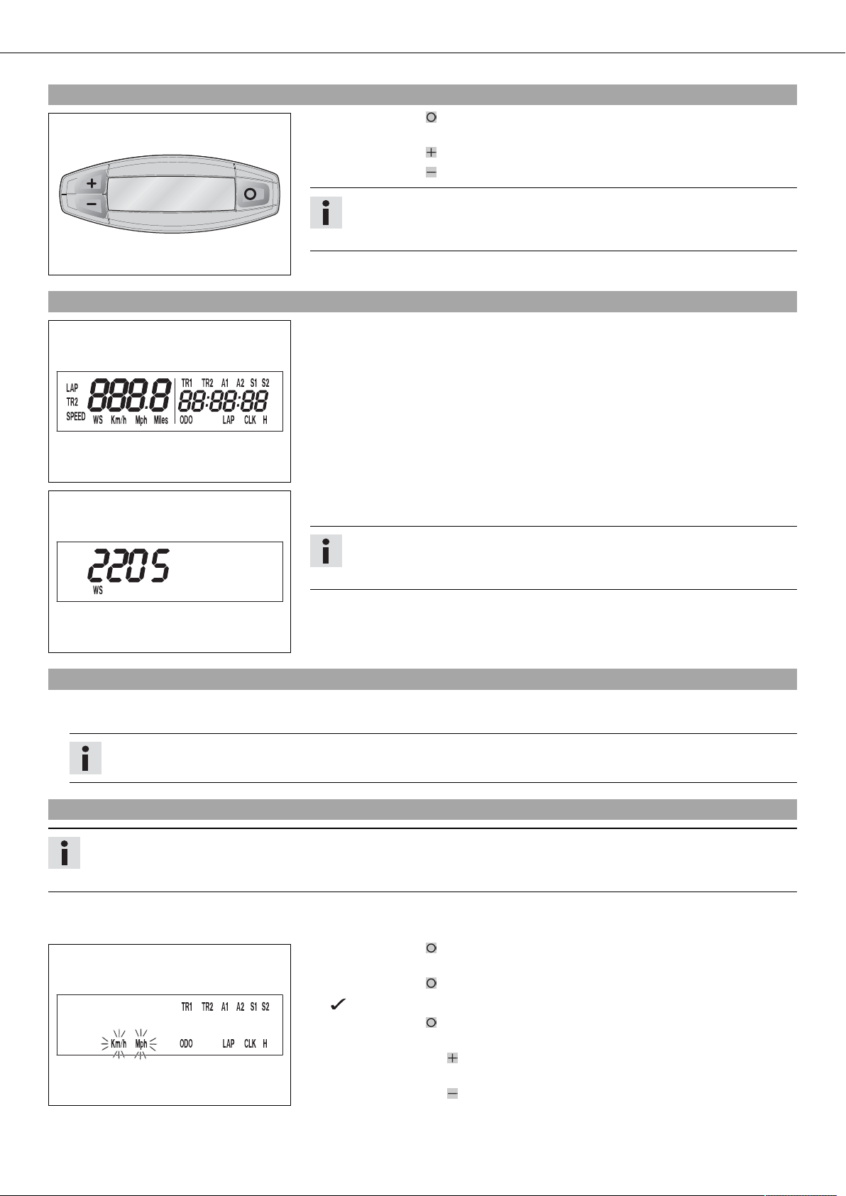
5.18Setting kilometers or miles
Info
If you change the unit of measure, the ODO value is retained and converted accordingly.
The values TR1, TR2, A1, A2 and S1 are cleared when the unit of measure is changed.
400329-01
Condition
The motorcycle is stationary.
– Press the button briefly and repeatedly until H appears at the bottom right of the
display.
– Press the button for 3 - 5 seconds.
The Setup menu is displayed and the active functions are shown.
– Press the button repeatedly until the Km/h/Mph display flashes.
Adjusting Km/h
– Press the button .
Adjusting Mph
– Press the button .
CONTROLS 16
– Press the button for 3 - 5 seconds.
The settings are stored and the Setup menu is closed.
Info
If no button is pressed for 20 seconds, or if no impulse comes from the
wheel speed sensor, the settings are automatically saved and the Setup
menu is closed.
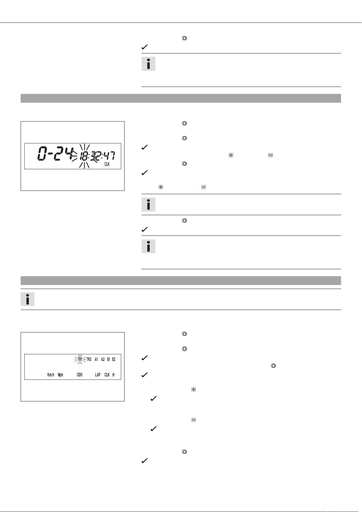
5.19Setting the clock
Condition
The motorcycle is stationary.
– Press the button briefly and repeatedly until CLK appears at the bottom right of
the display.
– Press the button for 3 - 5 seconds.
The hour display flashes.
– Set the hour display with the button and/or button .
– Press the button briefly.
The next segment of the display flashes and can be set.
– You can set the following segments in the same way as the hours by pressing the
400330-01
button and the button .
Info
The seconds can only be set to zero.
– Press the button for 3 - 5 seconds.
The settings are stored and the Setup menu is closed.
Info
If no button is pressed for 20 seconds, or if a pulse arrives from the wheel
speed sensor, the settings are stored automatically and the Setup menu is
closed.
5.20Adjusting the speedometer functions
Info
When the vehicle is delivered, only the SPEED/H and SPEED/ODO display modes are activated.
Condition
The motorcycle is stationary.
– Press the button briefly and repeatedly until H appears at the bottom right of the
display.
– Press the button for 3 - 5 seconds.
The Setup menu is displayed and the activated functions are shown.
– Change to the desired function by pressing the button briefly.
The selected function flashes.
Activating a function
– Press the button .
400318-01
Deactivating the function
– Press the button .
– All desired functions are activated or deactivated accordingly.
– Press the button for 3 - 5 seconds.
The symbol remains on the screen and the display changes to the next
function.
The symbol on the screen goes out and the display changes to the next
function.
The settings are stored and the Setup menu is closed.
CONTROLS 17
Info
If no button is pressed for 20 seconds, or if a pulse arrives from the wheel
speed sensor, the settings are stored automatically and the Setup menu is
closed.
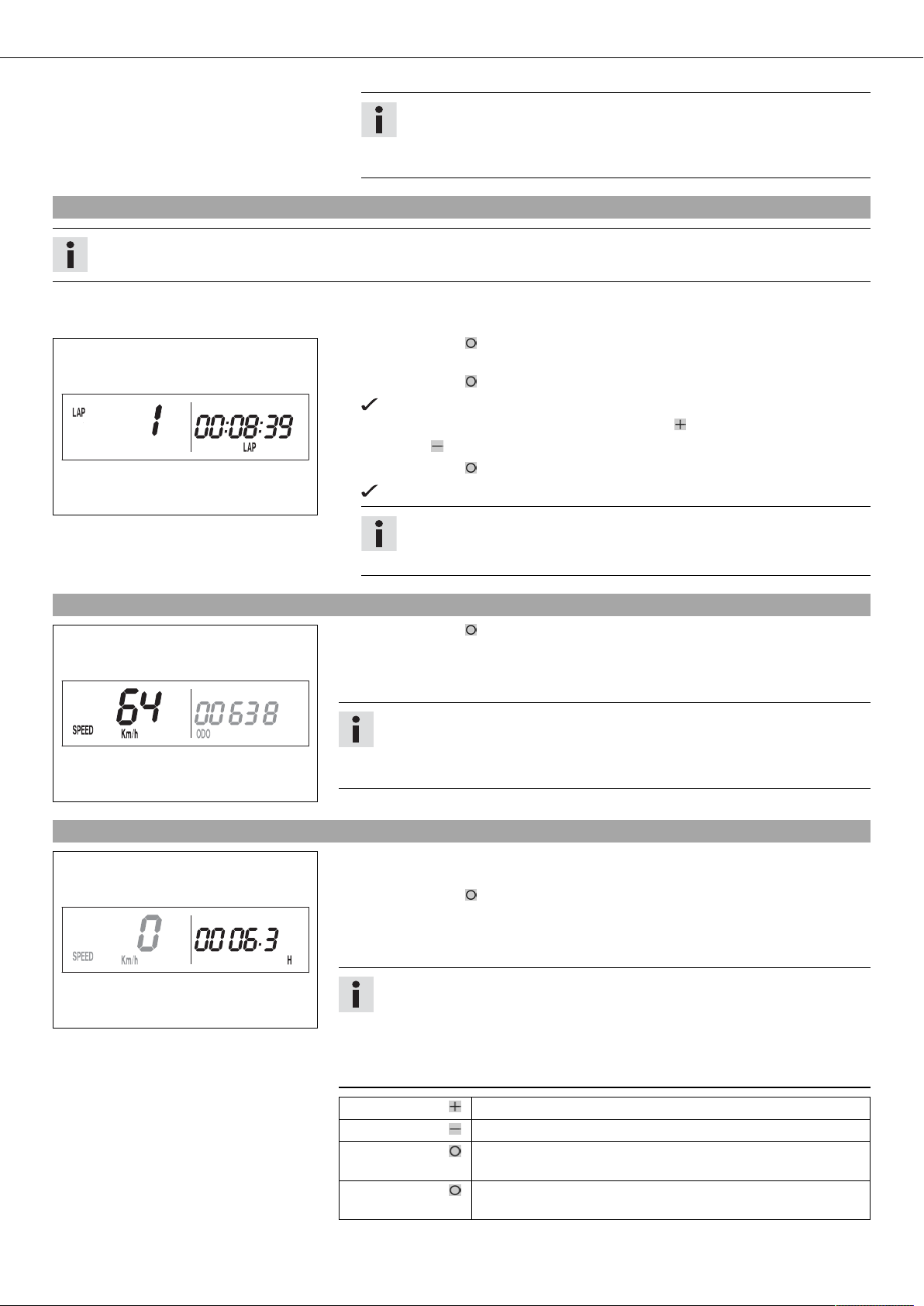
5.21Querying lap time
Info
This function can be called up only if lap times are measured.
Condition
The motorcycle is stationary.
– Press the button briefly and repeatedly until LAP appears at the bottom right of
the display.
– Press the button briefly.
LAP 1 appears on the left side of the display.
– Laps 1-10 can be displayed by pressing the button .
– The button has no function.
– Press the button briefly.
Next display mode
400321-01
Info
If an impulse is received from the wheel speed sensor, the left side of the
display changes back to the SPEED mode.
5.22Display mode SPEED (speed)
400317-02
5.23Display mode SPEED/H (operating hours)
400316-01
– Press the button briefly and repeatedly until SPEED appears on the left side of
the display.
The current speed is displayed in the SPEED display mode.
The current speed can be displayed in Km/h or Mph.
Info
Making the setting according to the country.
When an impulse comes from the front wheel, the left side of the speedometer
display changes to the SPEED mode and the current speed is shown.
Condition
• The motorcycle is stationary.
– Press the button briefly and repeatedly until H appears at the bottom right of the
display.
In display mode H, the operating hours of the engine are displayed.
The operating hours counter stores the total traveling time.
Info
The operating hours counter is necessary for ensuring that maintenance work is
carried out at the right intervals.
If the speedometer is in H display mode at the start of the journey, it automatically changes to the ODO display mode.
The H display mode is suppressed during the journey.
Press the button . No function
Press the button . No function
Press the button
for 3 - 5 seconds.
Press the button
The display changes to the Setup menu of the speedometer
functions.
Next display mode
briefly.
CONTROLS 18
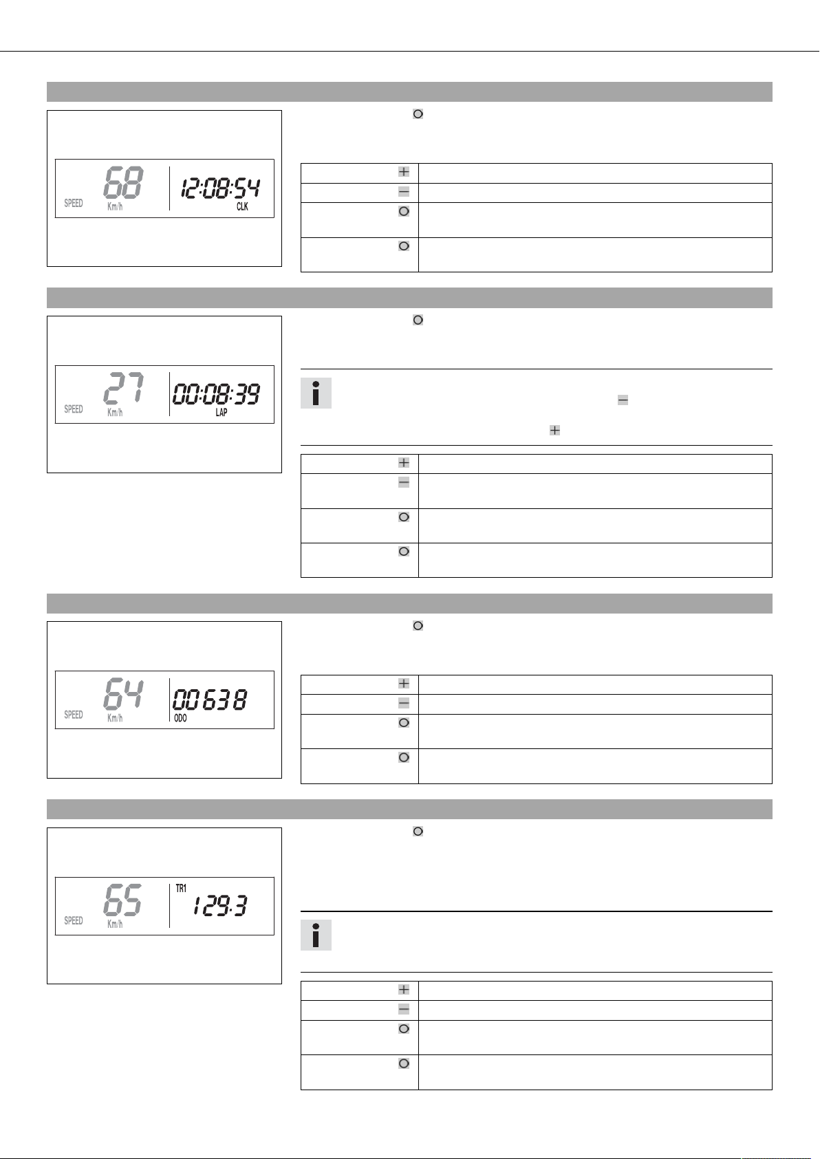
5.24Display mode SPEED/CLK (clock)
– Press the button briefly and repeatedly until CLK appears at the bottom right of
the display.
The time is displayed in CLK display mode.
Press the button . No function
Press the button . No function
400319-01
5.25Display mode SPEED/LAP (lap time)
Press the button
for 3 - 5 seconds.
Press the button
briefly.
– Press the button briefly and repeatedly until LAP appears at the bottom right of
the display.
In the LAP display mode, up to 10 lap times can be timed with the stop watch.
Info
If the lap time continues after you press the button , 9 memory locations are
already occupied.
Lap 10 must be timed with the button .
The display changes to the Setup menu of the clock.
Next display mode
400320-01
5.26Display mode SPEED/ODO (odometer)
400317-01
5.27Display mode SPEED/TR1 (trip master 1)
Press the button . Starts or stops the clock.
Press the button . Stops the current lap time and saves it, and the stop watch
starts the next lap.
Press the button
The stop watch and the lap time are reset.
for 3 - 5 seconds.
Press the button
Next display mode
briefly.
– Press the button briefly and repeatedly until ODO appears at the bottom right of
the display.
The total distance traveled is displayed in the ODO display mode.
Press the button . No function
Press the button . No function
Press the button
–
for 3 - 5 seconds.
Press the button
Next display mode
briefly.
– Press the button briefly and repeatedly until TR1 appears at the top right of the
display.
TR1 (trip master 1) runs constantly and counts to 999.9.
You can use it to measure trips or the distance between refueling stops.
TR1 is coupled with A1 (average speed 1) and S1 (stop watch 1).
400323-01
Info
If 999.9 is exceeded, the values of TR1, A1 and S1 are automatically reset to
0.0.
Press the button . No function
Press the button . No function
Press the button
for 3 - 5 seconds.
Press the button
briefly.
The TR1, A1 and S1 displays are reset to 0.0.
Next display mode
CONTROLS 19
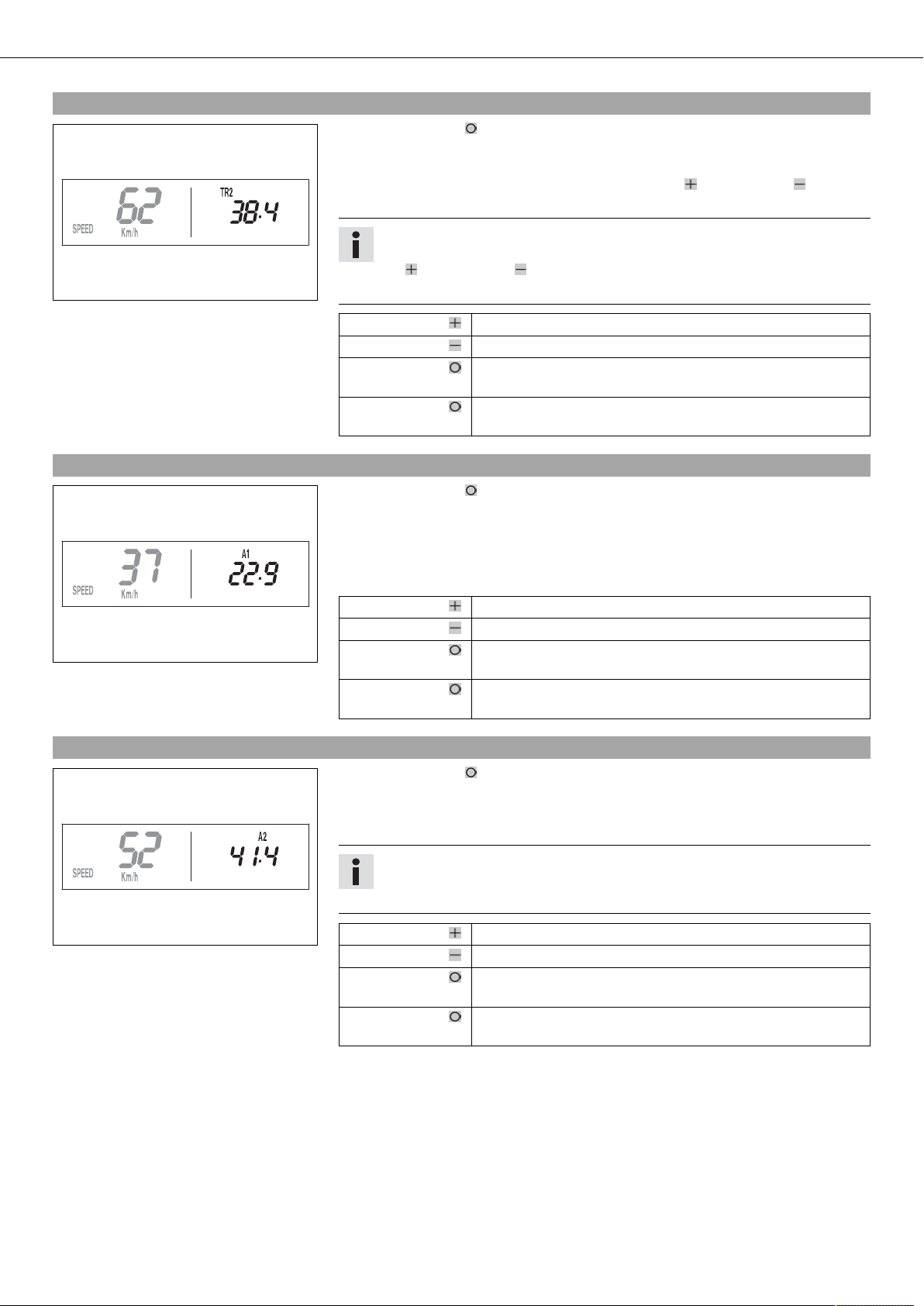
5.28Display mode SPEED/TR2 (trip master 2)
– Press the button briefly and repeatedly until TR2 appears at the top right of the
display.
TR2 (trip master 2) runs constantly and counts up to 999.9.
The displayed value can be set manually with the button and the button . This is a
very practical function when riding using the road book.
Info
The TR2 value can also be corrected manually during the journey with the button and the button .
400324-01
5.29Display mode SPEED/A1 (average speed 1)
If 999.9 is exceeded, the value of TR2 is automatically reset to 0.0.
Press the button . Increases value of TR2.
Press the button . Reduces value of TR2.
Press the button
Deletes value of TR2.
for 3 - 5 seconds.
Press the button
Next display mode
briefly.
– Press the button briefly and repeatedly until A1 appears at the top right of the
display.
A1 (average speed 1) shows the average speed calculated on the basis of TR1 (trip master 1) and S1 (stop watch 1).
The calculation of this value is activated by the first impulse of the wheel speed sensor
and ends 3 seconds after the last impulse.
400325-01
5.30Display mode SPEED/A2 (average speed 2)
– Press the button briefly and repeatedly until A2 appears at the top right of the
A2 (average speed 2) shows the average speed on the basis of the current speed if the
stop watch S2 (stop watch 2) is running.
400326-01
Press the button . No function
Press the button . No function
Press the button
The TR1, A1 and S1 displays are reset to 0.0.
for 3 - 5 seconds.
Press the button
Next display mode
briefly.
display.
Info
The displayed value can differ from the actual average speed if S2 was not
timed after the ride.
Press the button . No function
Press the button . No function
Press the button
for 3 - 5 seconds.
Press the button
briefly.
–
Next display mode
CONTROLS 20
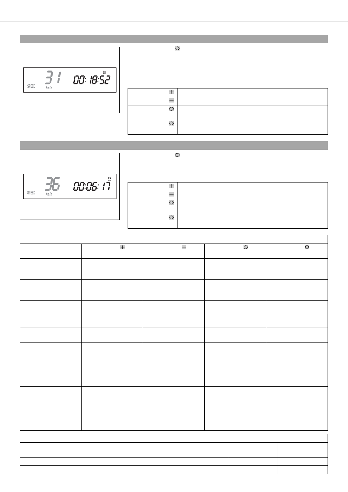
5.31Display mode SPEED/S1 (stop watch 1)
– Press the button briefly and repeatedly until S1 appears at the top right of the
display.
S1 (stop watch 1) displays the journey time on the basis of TR1 and continues when an
impulse is received from the wheel speed sensor.
The calculation of this value starts with the first impulse of the wheel speed sensor and
ends 3 seconds after the last impulse.
Press the button . No function
Press the button . No function
400327-01
5.32Display mode SPEED/S2 (stop watch 2)
400328-01
Press the button
for 3 - 5 seconds.
Press the button
briefly.
– Press the button briefly and repeatedly until S2 appears at the top right of the
display.
S2 (stop watch 2) is a manual stop watch.
If S2 is running in the background, the S2 display flashes in the speedometer display.
Press the button . Starts or stops S2.
Press the button . No function
Press the button
for 3 - 5 seconds.
Press the button
briefly.
Displays of TR1, A1 and S1 are reset to 0.0.
Next display mode
Displays of S2 and A2 are reset to 0.0.
Next display mode
Table of functions
Display Press the button . Press the button . Press the button for 3 -
5 seconds.
Display mode SPEED/H
(operating hours)
No function No function The display changes to
the Setup menu of the
speedometer functions.
Display mode SPEED/CLK
(clock)
No function No function The display changes to
the Setup menu of the
clock.
Display mode SPEED/LAP
(lap time)
Starts or stops the
clock.
Stops the current lap
time and saves it, and
The stop watch and the
lap time are reset.
the stop watch starts
the next lap.
Display mode
No function No function – Next display mode
SPEED/ODO (odometer)
Display mode SPEED/TR1
(trip master 1)
Display mode SPEED/TR2
No function No function The TR1, A1 and S1 dis-
plays are reset to 0.0.
Increases value of TR2. Reduces value of TR2. Deletes value of TR2. Next display mode
(trip master 2)
Display mode SPEED/A1
(average speed 1)
Display mode SPEED/A2
No function No function The TR1, A1 and S1 dis-
plays are reset to 0.0.
No function No function – Next display mode
(average speed 2)
Display mode SPEED/S1
(stop watch 1)
Display mode SPEED/S2
(stop watch 2)
No function No function Displays of TR1, A1 and
S1 are reset to 0.0.
Starts or stops S2. No function Displays of S2 and A2
are reset to 0.0.
Press the button
briefly.
Next display mode
Next display mode
Next display mode
Next display mode
Next display mode
Next display mode
Next display mode
Table of conditions and menu activation
Display The motorcycle is
stationary.
Menu can be activated
Display mode SPEED/H (operating hours) •
Display mode SPEED/CLK (clock) •

CONTROLS 21
Table of conditions and menu activation
Display The motorcycle is
stationary.
Display mode SPEED/LAP (lap time) •
Display mode SPEED/TR1 (trip master 1) •
Display mode SPEED/TR2 (trip master 2) •
Display mode SPEED/A1 (average speed 1) •
Display mode SPEED/A2 (average speed 2) •
Display mode SPEED/S1 (stop watch 1) •
Display mode SPEED/S2 (stop watch 2) •
5.33Fuel tap
The fuel tap is on the left side of the fuel tank.
Tap handle on the fuel tap is used to open or close the supply of fuel to the carburetor.
Possible states
• Fuel supply closed OFF – No fuel can flow from the tank to the carburetor.
• Fuel supply open ON – Fuel can flow from the tank to the carburetor. The fuel tank
empties down to the reserve.
• Reserve fuel supply open RES – Fuel can flow from the tank to the carburetor. The
fuel tank empties completely.
Menu can be activated
601157-10
5.34Opening the filler cap
Danger
Fire hazard Fuel is highly flammable.
– Never refuel the vehicle near open flames or burning cigarettes, and always switch off the engine first. Be careful that no
fuel is spilt, especially on hot vehicle components. Clean up spilt fuel immediately.
– Fuel in the fuel tank expands when warm and can escape if the tank is overfilled. See the notes on refueling.
Warning
Danger of poisoning Fuel is poisonous and a health hazard.
– Avoid contact between fuel and skin, eyes and clothing. Do not inhale fuel vapors. If fuel gets into your eyes, rinse immedi-
ately with water and contact a doctor. Wash affected skin areas immediately with soap and water. If fuel is swallowed, contact a doctor immediately. Change clothing that has come into contact with fuel. Store fuel in a suitable canister according
to regulations and keep it out of the reach of children.
Warning
Environmental hazard Improper handling of fuel is a danger to the environment.
– Do not allow fuel to get into the ground water, the ground, or the sewage system.
CONTROLS 22
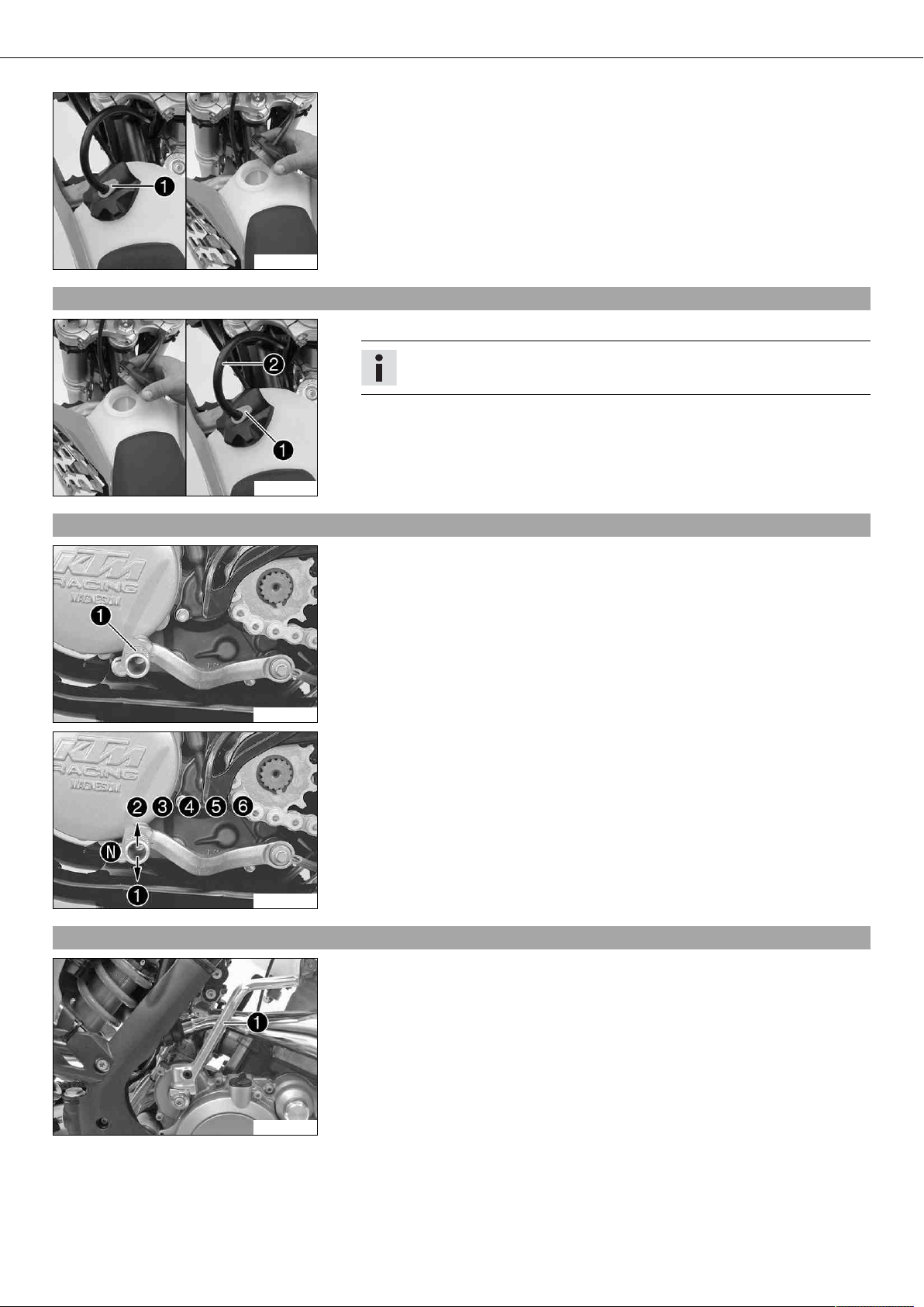
– Press release button , turn the filler cap counterclockwise and lift it free.
303520-10
5.35Closing the filler cap
– Replace the filler cap and turn clockwise until the release button locks in place.
Info
Run the fuel tank breather hose without kinks.
303521-10
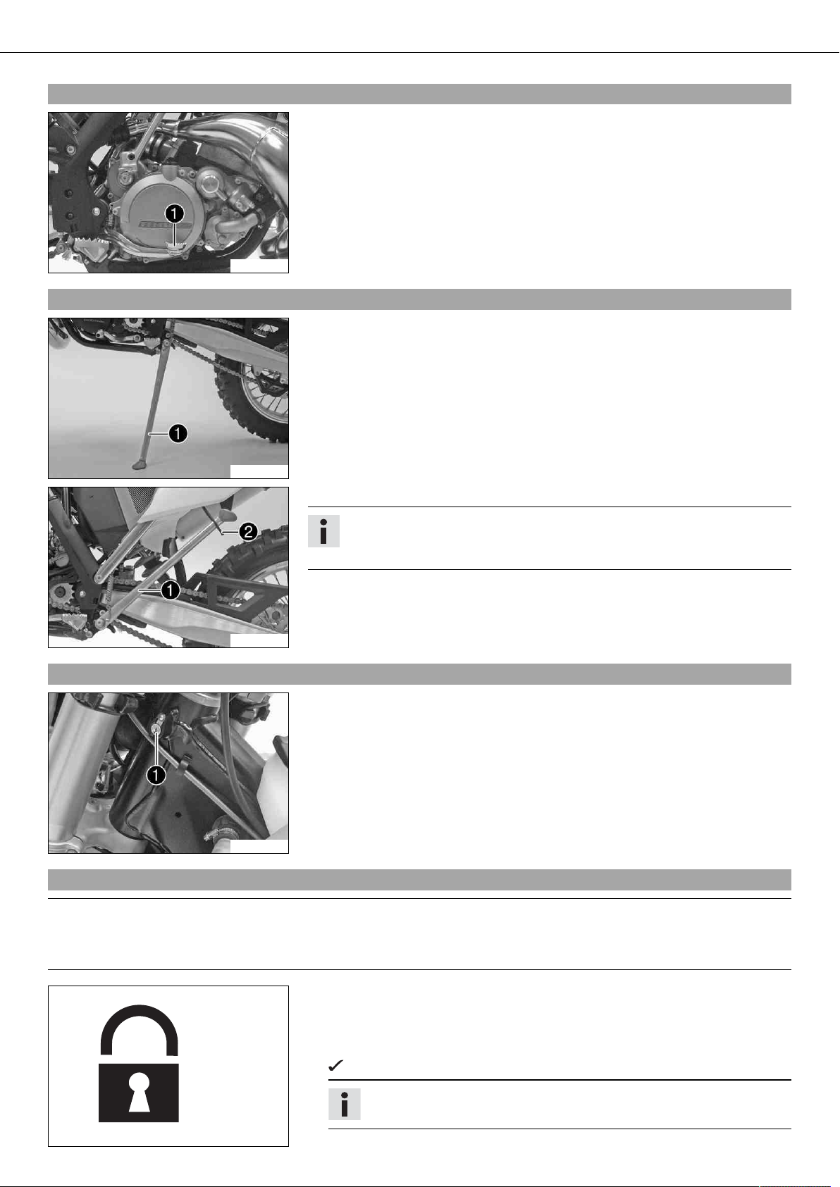
5.36Shift lever
5.37Kickstarter
Shift lever is mounted on the left side of the engine.
B00005-10
The gear positions can be seen in the photograph.
The neutral or idle position is between the first and second gears.
B00005-12
The kickstarter is fitted on the right side of the engine. The top part can be
swiveled.
B00787-10
CONTROLS 23
5.38Foot brake lever
Foot brake lever is located in front of the right footrest.
The foot brake lever is used to activate the rear brake.
B00788-10
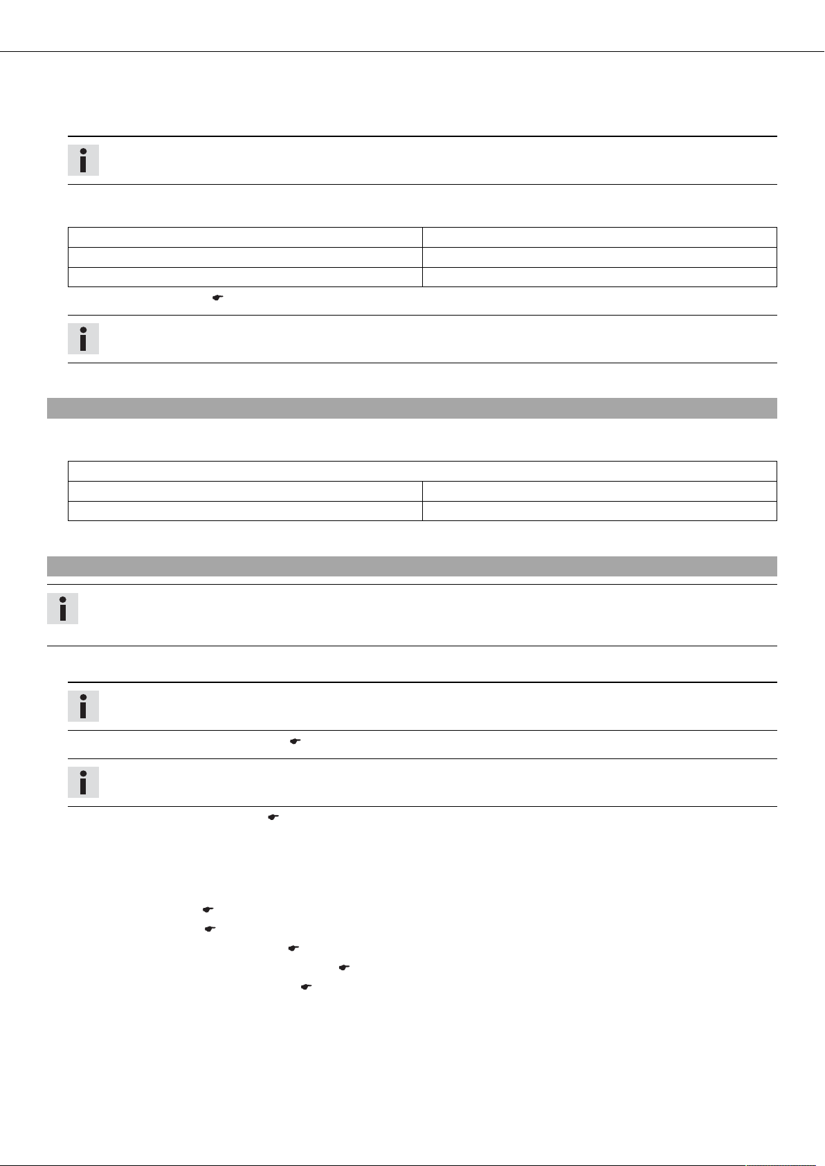
5.39Side stand
The side stand is on the left side of the vehicle.
B00789-10
B00790-10
5.40Steering lock (All EXC models)
B00791-10
The side stand is used to park the motorcycle.
Info
When you are riding, side stand must be folded up and secured with rubber
band .
Steering lock is fitted on the left side of the steering head.
The steering lock is used to lock the steering. Steering, and therefore riding, is no
longer possible.
5.41Locking the steering (All EXC models)
Note
Danger of damage The parked vehicle may roll away or fall over.
– Always place the vehicle on a firm and even surface.
– Park the vehicle.
– Turn the handlebar as far as possible to the right.
– Insert the key in the steering lock, turn it to the left, press it in and turn it to the
right. Remove the key.
Steering is no longer possible.
Info
Never leave the key in the steering lock.
400732-01

CONTROLS 24
5.42Unlocking the steering (All EXC models)
– Insert the key in the steering lock, turn it to the left, pull it out and turn it to the
right. Remove the key.
You can now steer the bike again.
Info
Never leave the key in the steering lock.
400731-01

PREPARING FOR USE 25
6.1Advice on first use
Danger
Danger of accidents Danger arising from the rider's judgement being impaired.
– Do not operate the vehicle while under the influence of alcohol, drugs and certain medications or physically or mentally
impaired.
Warning
Risk of injury Missing or poor protective clothing present an increased safety risk.
– Wear protective clothing (helmet, boots, gloves, pants and jacket with protectors) every time you ride the vehicle. Always
wear protective clothing, which must be undamaged and meet legal requirements.
Warning
Danger of crashing Poor vehicle handling due to different tire tread patterns on front and rear wheels.
– The front and rear wheels must be fitted with tires with similar tread patterns to prevent loss of control over the vehicle.
Warning
Danger of accidents Critical riding behavior due to inappropriate riding.
– Adapt your riding speed to the road conditions and your riding ability.
Warning
Danger of accidents Accident risk caused by presence of a passenger.
– Your vehicle is not designed to carry passengers. Do not ride with a passenger.
Warning
Danger of accidents Failure of brake system.
– If the foot brake lever is not released, the brake linings drag continuously. The rear brake may fail due to overheating. Take
your foot off the foot brake lever when you are not braking.
Warning
Danger of accidents Unstable riding behavior.
– Do not exceed the maximum permissible weight and axle loads.
Warning
Risk of misappropriation Usage by unauthorized persons.
– Never leave the vehicle while the engine is running. Secure the vehicle against use by unauthorized persons.
Info
When using your motorcycle, remember that others may feel disturbed by excessive noise.
– Make sure that the pre-delivery inspection work has been carried out by an authorized KTM workshop.
You receive a delivery certificate and the service record at vehicle handover.
– Before your first trip, read the entire operating instructions carefully.
– Get to know the controls.
– Adjust the basic position of the clutch lever. ( p. 66)
(XC-W)
– Adjust the basic position of the hand brake lever. ( p. 69)
(All EXC models)
– Adjust the free travel of the hand brake lever. ( p. 69)
–
Adjust the basic position of the foot brake lever. x ( p. 73)
–
Adjust the basic position of the shift lever. x ( p. 96)
– Get used to handling the motorcycle on a suitable piece of land before making a longer trip.
Info
Offroad, you should be accompanied by another person on another machine so that you can help each other.
– Try also to ride as slowly as possible and in a standing position to get a better feeling for the vehicle.
– Do not make any offroad trips that over-stress your ability and experience.
PREPARING FOR USE 26
– Hold the handlebar firmly with both hands and keep your feet on the footrests when riding.
– If you carry any baggage, make sure it is fixed firmly as close as possible to the center of the vehicle and ensure even weight dis-
tribution between the front and rear wheels.
Info
Motorcycles react sensitively to any changes of weight distribution.
– Do not exceed the overall maximum permitted weight and the axle loads.
Guideline
Maximum permissible overall weight 335 kg (739 lb.)
Maximum permissible front axle load 145 kg (320 lb.)
Maximum permissible rear axle load 190 kg (419 lb.)
– Check the spoke tension. ( p. 81)
Info
The spoke tension must be checked after half an hour of operation.
– Run the engine in.
6.2Running in the engine
– During the running-in phase, do not exceed the specified engine performance.
Guideline
Maximum engine performance
During the first 3 operating hours < 70 %
During the first 5 operating hours < 100 %
– Avoid fully opening the throttle!
6.3Preparing the vehicle for difficult operating conditions
Info
Using a motorcycle in difficult conditions can lead to excessive wear of components such as the power train or brakes. For this
reason, it may be necessary to service or replace worn parts before the limit specified in the service schedule is reached.
–
Seal the air filter box. x
Tip
Seal the air filter box at the edges against dirt.
–
Clean the air filter and air filter box. x ( p. 57)
Info
Check the air filter approx. every 30 minutes.
– Additionally secure the rubber grip. ( p. 66)
– Check the electrical connector for humidity and corrosion and to ensure it is firmly seated.
» If humidity, corrosion, or damage is found:
– Clean and dry the connector, or change it if necessary.
Difficult operating conditions are:
– Riding on dry sand. ( p. 27)
– Riding on wet sand. ( p. 27)
– Riding on wet and muddy surfaces. ( p. 28)
– Riding at high temperatures and low speeds. ( p. 28)
– Rides at low temperatures or in snow. ( p. 29)
PREPARING FOR USE 27
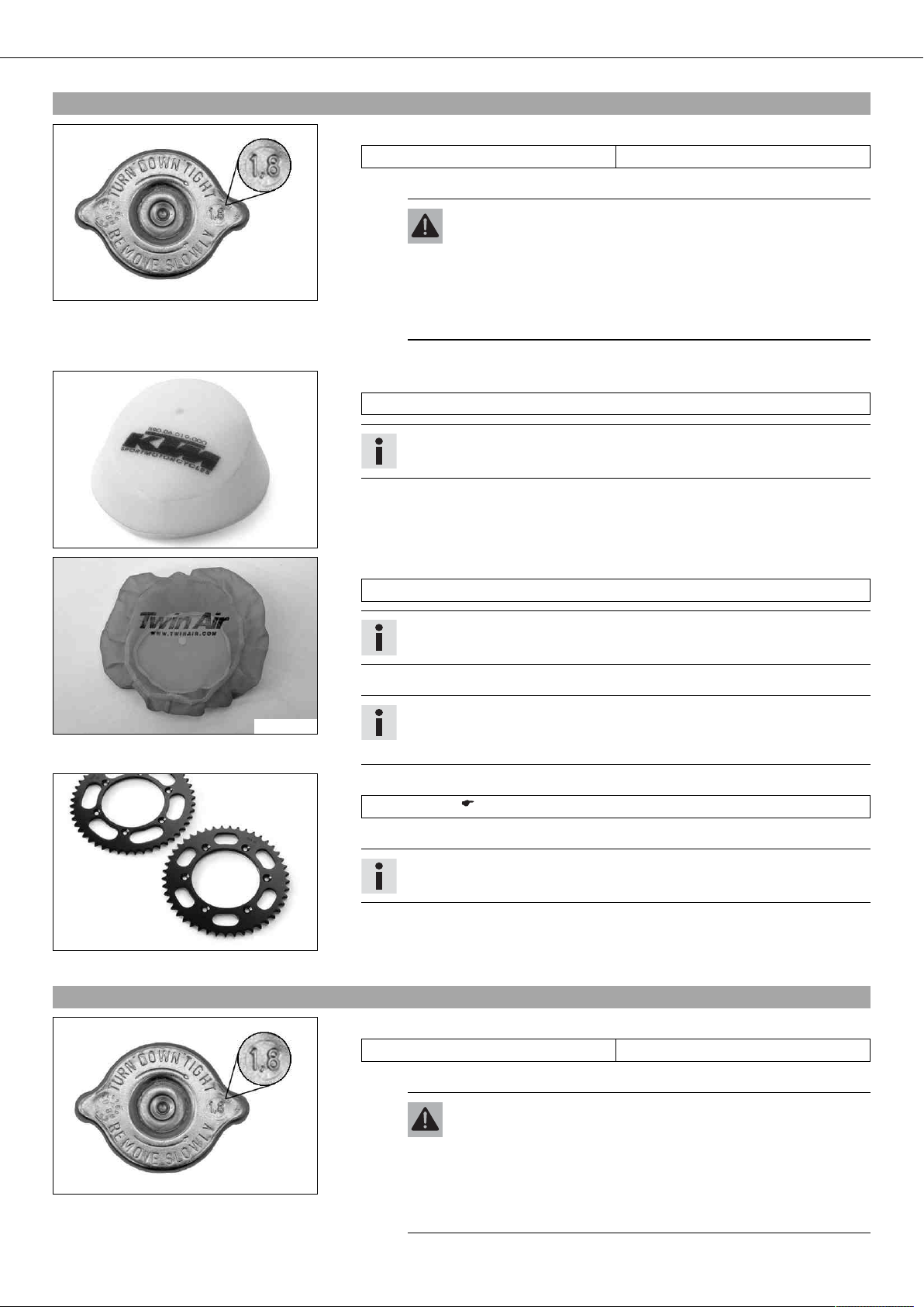
6.4Preparations for riding on dry sand
– Check the radiator cap.
Value on the radiator cap 1.8 bar (26 psi)
» If the displayed value does not equal the setpoint value:
Warning
Danger of scalding During motorcycle operation, the coolant gets
very hot and is under pressure.
– Do not remove the radiator cap, radiator hoses or other cooling
600872-10
– Change the radiator cap.
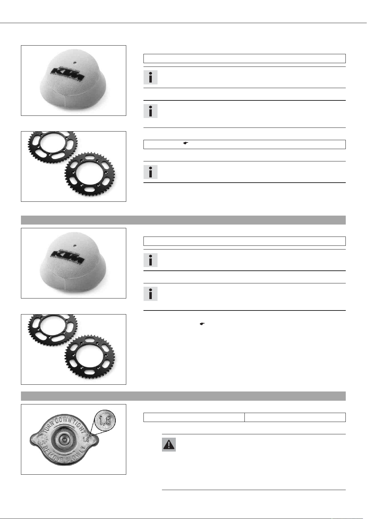
– Mount the dust cover for the air filter.
Dust cover for air filter (59006019000)
Info
Read the KTM PowerParts installation instructions.
system components when the engine is hot. Allow the engine
and cooling system to cool down. In case of scalding, rinse
immediately with lukewarm water.
600869-01
600871-01
600868-01
– Mount the dust cover for the air filter for sand.
Sand cover for air filter (59006022000)
Info
Read the KTM PowerParts installation instructions.
– Adjust the carburetor jetting and setting.
Info
Recommendations on the carburetor setting are available from your authorized KTM workshop.
– Clean the chain.
Chain cleaner ( p. 128)
– Mount the steel sprocket.
Tip
Do not grease the chain.
– Clean the radiator fins.
– Carefully align bent radiator fins.
– If used in sand regularly, replace the piston every 10 operating hours.
6.5Preparations for riding on wet sand
600872-10
– Check the radiator cap.
Value on the radiator cap 1.8 bar (26 psi)
» If the displayed value does not equal the setpoint value:
Warning
Danger of scalding During motorcycle operation, the coolant gets
very hot and is under pressure.
– Do not remove the radiator cap, radiator hoses or other cooling
system components when the engine is hot. Allow the engine
and cooling system to cool down. In case of scalding, rinse
immediately with lukewarm water.
PREPARING FOR USE 28
– Change the radiator cap.
– Mount the rain cover for the air filter.
Rain cover for air filter (59006021000)
Info
Read the KTM PowerParts installation instructions.
– Adjust the carburetor jetting and setting.
600870-01
– Clean the chain.
Chain cleaner ( p. 128)
– Mount the steel sprocket.
– Clean the radiator fins.
600868-01
– Carefully align bent radiator fins.
– If used in sand regularly, replace the piston every 10 operating hours.
6.6Preparations for riding on wet and muddy surfaces
– Mount the rain cover for the air filter.
Rain cover for air filter (59006021000)
– Adjust the carburetor jetting and setting.
Info
Recommendations on the carburetor setting are available from your authorized KTM workshop.
Tip
Do not grease the chain.
Info
Follow the KTM PowerParts mounting instructions.
600870-01
– Mount the steel sprocket.
– Clean the motorcycle. ( p. 101)
– Carefully align bent radiator fins.
600868-01
6.7Preparations for riding at high temperatures and low speeds
– Check the radiator cap.
The recommended carburetor tuning is available from your authorized KTM
workshop.
Value on the radiator cap 1.8 bar (26 psi)
» If the displayed value does not equal the setpoint value:
Warning
Danger of scalding During motorcycle operation, the coolant gets
very hot and is under pressure.
– Do not remove the radiator cap, radiator hoses or other cooling
600872-10
Info
system components when the engine is hot. Allow the engine
and cooling system to cool down. In case of scalding, rinse
immediately with lukewarm water.
 Loading...