

Page 1

Elektrowerkzeuge
®
D
GB
F
NL
I
E
S
DK
N
SF
GR
750 FDF
45690/0302 TC
Flachdübelfräse
Bedienungsanleitung
Flat mortise router
Operating Instructions
Fraiseuse pour chevilles plates
Mode d’emploi
Platte plugfrees
Gebruiksaanwijzing
Fresa per tasselli piatti
Manuale di servizio
Fresadora de tacos planos
Instrucciones de servicio
Tappfräs
Bruksanvisyning
Fladdyvelfræser
Betjeningsvejledning
Tappfres
Bruksanvisning
Tasovaarnajyrsin
Käyttöohje
Kαβιλιέρα (πλακέ καβίλιασ)
Oδηγίες χρήσης
Page 2

Page 3

Page 4

Page 5

Deutsch
1 Einstellrad
2 Schwenkanschlag
3 Skala
4 Säulenführung rechts
5 Markierung
6 Träger
7 Grundplatte
8 Schaltring
9 Wipphebel
10 Vorderkante
11 Drehgriff
12 Bogengriff
13 Motorgehäuse
14 Auswurfrohr
15 Spänesack
16 Absaugstutzen
17 Netzkabelmodul
18 Verriegelungstaste
19 Senkschraube
20 Drücker
21 Spindel
22 Flanschmutter
23 Fräser
24 Schneidezahn
25 Mutter
26 Tiefenanschlag
27 Revolveranschlag
28 Spannflansch
29 Frässchutzanschlag
Technische Daten 750 FDF
Leistungsaufnahme in Watt 750
Leistungsabgabe in Watt 400
Leerlaufdrehzahl min
-1
9800
Spindelgewinde M10
Aufnahme Ø 22
Fräs-Ø max. in mm 100
Fräsblatt-/Nabendicke 4/3
Schnittiefe in mm 19
Schwenkbereich in ° 0–90
Gewicht ca. in kg 3,2
Verwendung
Die Flachdübelfräse 750 FDF ist einsetzbar zum Fräsen von
Nuten in den verschiedenen Materialien Massivholz, Sperrholz, Spanplatten, Faserplatten, Plexiglas und Kunstmarmor
für die Dübelarten Nr. 0, 10, 20, S6, H9, Simplex und Duplex
sowie zum Ausfräsen von Harzgallen in Massivholz.
Sicherheitsbestimmungen und Hinweise, die Sie vor Inbetriebnahme unbedingt lesen sollten und deren Beachtung wir dringend empfehlen:
1. Vor Arbeiten am Motor Netzstecker ziehen. Das gilt
vor allem beim Einspannen der Fräser oder sonstiger Werkzeuge und bei Service-Arbeiten.
2. Werkstück wenn möglich fest einspannen.
3. Achten Sie darauf, daß die Fräser scharf sind.
Stumpfe Werkzeuge bringen unsaubere Fräsarbeiten und führen zu einer unnötigen Überlastung des
Motors.
4. Achten Sie beim Ablegen des Fräsmotors darauf,
daß das Gerät ausgeschaltet ist.
5. Zum Schutz vor unbeabsichtigter Inbetriebnahme
bei längerer Arbeitsunterbrechung Netzstecker ziehen!
6. Nur Fräser für Handvorschub verwenden.
7. Der Motorteil der Flachdübelfräse 750 FDF muß
klemmfrei (leichtgängig) einwandfrei funktionieren.
8. Der Träger darf bei ausgefahrenem Fräser nicht
festgeklemmt werden.
9. Arbeiten Sie immer mit Schutzbrille und Gehörschutz.
10. Verwenden Sie immer das Auswurfrohr oder den
Auswurfstutzen.
11. Führen Sie das Gerät immer zweihändig am Bogengriff und am Motorgehäuse.
12. Die Maschine nur für die in der Bedienungsanleitung beschriebenen Arbeiten verwenden.
13. Die beiden Drehgriffe (11) des Schwenkanschlages
müssen beim Fräsen fest angezogen sein.
14. Steckdosen im Außenbereich müssen über Fehlerstrom-Schutzschalter (FI-) abgesichert sein.
15. Um die Maschine zu kennzeichnen, darf das
Gehäuse nicht angebohrt werden. Die Schutzisolation wird überbrückt. Verwenden Sie Klebeschilder.
16. Kabel immer nach hinten von der Maschine wegführen.
Sicherheitshinweise und Unfallschutz
Bevor Sie die Maschine in Betrieb nehmen, lesen Sie die
Bedienungsanleitung vollständig durch, befolgen Sie die
Sicherheitshinweise in dieser Anleitung sowie die Allgemeinen Sicherheitshinweise für Elektrowerkzeuge im
beigelegten Heft.
Doppelte Isolation
Unsere Geräte sind zur größtmöglichen Sicherheit des Benutzers in Übereinstimmung mit den Europäischen Vorschriften (EN-Norm) gebaut. Doppelt isolierte Maschinen
tragen stets das internationale Zeichen . Die Maschinen
brauchen nicht geerdet zu sein. Es genügt ein zweiadriges
Kabel.
Die Maschinen sind funkentstört nach EN 55014.
Inbetriebnahme
Prüfen Sie vor Inbetriebnahme, ob die Netzspannung mit
der Angabe auf dem Typenschild des Gerätes übereinstimmt.
Verbindungsarten
Mit der Flachdübelfräse 750 FDF lassen sich die folgenden
Verbindungsarten in den Materialien Massivholz, Sperrholz, Spanplatten, Faserplatten, Plexiglas und Kunstmarmor herstellen.
Wahl der Dübelgrößen
Materialdicke Dübelgröße Abmessung
8–12 0 47 x 15 x 4 mm
12–15 10 53 x 19 x 4 mm
>15 20 56 x 23 x 4 mm
Für eine optimale Verbindung ist immer der größtmögliche
Dübel einzusetzen. Für Materialstärken über 25 mm können 2 Dübel übereinander eingesetzt werden.
Eckverbindung Längs- oder
Querverbindung
Mittelwandverbindung
Gehrungsverbindung Rahmenverbindung
Page 6

Frästiefeneinstellung
Die Frästiefe wird mit dem Einstellrad (1) entsprechend
dem gewählten Dübel eingestellt.
Dübel Einstellung Frästiefe
Nr. 0 0 8,0 mm
Nr. 10 10 10,0 mm
Nr. 20 20 12,3 mm
Simplex S 13,0 mm
Duplex D 14,7 mm
maximal max. 19,0 mm
Achtung! Unfallgefahr
● Arbeiten Sie immer mit eingeklipstem Frässchutz-
anschlag (29)
Nuthöheneinstellung mit Schwenkanschlag 90°
Die Nuthöhe kann über den höhenverstellbaren Schwenkanschlag (2) und der Skala (3) an der Säulenführung rechts
genau nach der Materialdicke eingestellt werden. Dabei
muß der Frässchutzanschlag (29) im Schwenkanschlag (2)
eingeklipst sein, einzig in der 0°-Stellung (für Mittelwandverbindungen) muß der Frässchutzanschlag (29) entfernt
werden. Mit Hilfe des Revolveranschlages (27) können
3 Materialdicken voreingestellt werden. Werkseitig eingestellt für die Plattendicken 16, 19 und 25 mm.
Nuthöheneinstellung mit Schwenkanschlag 0°–90°
Die Nuthöhe kann über den höhenverstellbaren Schwenkanschlag (2) eingestellt werden. Die genaue Höhe der Nut
muß durch Versuche ermittelt werden. Dabei muß der
Frässchutzanschlag (29) im Schwenkanschlag (2) eingeklipst sein. Mit Hilfe des Revolveranschlages (27) können
so 3 Materialdicken voreingestellt werden. Dabei muß die
6kt-Mutter gelöst werden, die 6kt-Schraube auf das gewünschte Maß eingestellt und die Mutter wieder festgezogen werden.
Späneauswurf und Absaugung
Als Zubehör liegen ein Auswurfrohr (14), ein Spänesack
(15) und ein Absaugstutzen (16) bei. Auswurfrohr (14) oder
Absaugstutzen (16) können im Träger (6) eingeklipst werden. Damit werden die Späne nicht nach hinten, sondern
seitlich ausgeworfen. Der Spänesack (15) kann auf den Absaugstutzen (16) aufgesteckt werden. Damit werden die
Späne direkt in den Spänesack (15) ausgeworfen. Bei stationärem Betrieb empfiehlt sich das Anschließen eines
handelsüblichen Staubsaugers. Beim Fräsen von Eichenund Buchenholz muß in einigen Ländern ein Staubsauger
angeschlossen werden.
Ein- und Ausschalten der Maschine
Durch Drehen des Schaltringes (8) in Pfeilrichtung wird die
Maschine in Betrieb gesetzt. Am Ende des Drehbereichs
rastet der Wipphebel (9) automatisch ein. Drücken auf die
ausgekippte Vorderkante (10) des Wipphebels (9) bewirkt,
daß dieser auslöst und sich der Schaltring (8) automatisch
in die Ausgangsstellung zurückdreht. Die Maschine kommt
zum Stillstand.
Nutabstände anreißen
In der Regel sind die Nutabstände zwischen 10 und 15 cm
zu wählen. Die Mitte der ersten Nut sollte 4–6 cm von der
Außenkante des Werkstückes zum Liegen kommen. Es
empfiehlt sich, die Nutmitten jeweils auf den Werkstücken
anzureißen. Für schmale Werkstücke können die Nuten mit
Hilfe der Markierungen (5) auf dem Träger (6), Schwenkanschlag (2) oder der Grundplatte (7) direkt gefräst werden.
Achtung! Unfallgefahr
● Schutzbrille und Gehörschutz tragen.
● Gerät immer zweihändig am Bogengriff und am Mo-
torgehäuse führen.
● Bei laufender Maschine Fräsöffnung nicht gegen
das Gesicht richten.
● Bei laufender Maschine nicht in die Auswurföffnung
greifen.
● Netzstecker ziehen, wenn Späne entfernt werden
müssen.
● Nicht in den Bereich des Fräsers greifen.
Fräsen der Nuten
Um die Nuten zu fräsen, geht man wie folgt vor: Die Flachdübelfräse 750 FDF wird mit der Mittelmarkierung (5) auf
dem Träger (6) auf die zuvor am Werkstück angerissene
Markierung positioniert. Bei Gehrungsverbindungen ist zusätzlich mit Hilfe der beiden Drehgriffe (11) und des
Schwenkanschlages (2) die Höhe- und die Winkellage einzustellen. Die Maschine wird eingeschaltet. Die Nut wird
gefräst, durch Vorschieben des Motorteils der Flachdübelfräse 750 FDF bis zum vorgewählten Anschlag. Dabei ist
das Gerät mit beiden Händen zu halten, am Bogengriff (12)
und am Motorgehäuse (13) hinten. Bei nachlassendem
Vorschubdruck wird der Motorteil automatisch wieder in
die Ausgangsposition zurückgezogen. Bei schmalen Werkstücken, bei denen nur 1 oder 2 Nuten gefräst werden,
können Sie an Hand der Markierungen (5) auf dem Träger
(6) die Position der Nuten wählen.
Leimen und Spannen
Die Nuten am Werkstück werden mit Leim versehen. Danach werden die Dübel in die Nuten eingesetzt und die
Werkstücke zusammengefügt. Um eine gute Verbindung
zu erreichen, müssen die Werkstücke anschließend mit
Schraubzwingen oder anderen Spannmitteln zusammengespannt werden.
Fräsen der verschiedenen Verbindungsarten
Eckverbindung:
● mit eingeklipstem Frässchutzanschlag (29)
● mit Höhenverstellung stufenlos über Skala (3) an der
Säulenführung rechts (4)
● mit voreingestellter Höhe am Revolveranschlag-System
(27)
Gehrungsverbindung:
● mit eingeklipstem Frässchutzanschlag (29)
● mit verstellbarem Schwenkanschlag (2)
Rahmenverbindung:
● mit eingeklipstem Frässchutzanschlag (29)
● mit 2 Dübeln über 25 mm Plattendicke
● mit normaler Geräteeinstellung und gedrehtem Werk-
stück für zweite Fräsnut
● mit Schwenkanschlag (2) für variablen Randabstand
und gedrehtem Werkstück für zweite Fräsnut
Mittelwandverbindung:
in waagerechter Anwendung mit Schwenkanschlag 90°
● mit eingeklipstem Frässchutzanschlag (29)
in senkrechter Anwendung mit Schwenkanschlag 0°
● ohne eingeklipsten Frässchutzanschlag (29)
Längs- und Querverbindung:
in waagerechter Anwendung mit Schwenkanschlag 90°
● mit eingeklipstem Frässchutzanschlag (29)
● mit Schwenkanschlag (2) für variablen Randabstand
Harzgallen fräsen
Dies läßt sich mit einem speziellen Fräser (Sonderzubehör)
herstellen. Bei der Erstanwendung muß die Schlitzbreite im
Träger (6) zuerst frei gefräst werden. Dies erfolgt, indem
der spez. Harzgallenfräser bis zum max. Frästiefenanschlag nach vorne gedrückt wird und sich dadurch die erforderliche Öffnung im Träger (6) freifräst.
3
2
1
Page 7

Besondere Dübel
Dübel S6
Für Verbindungen mit Plattenstärken ab 30 mm wie z. B.
Türrahmen, Treppen oder Bettgestelle empfiehlt sich der
Einsatz des Dübels S6. Dabei müssen Sie wie folgt vorgehen. Die Frästiefe am Einstellrad (1) auf max. stellen und
die Nut wie bei normalen Dübeln fräsen. Anschließend ist
die Flachdübelfräse 750 FDF um 10 mm zu versetzen und
der Fräser muß nochmals eingetaucht werden.
Dübel H9
Für Rahmenverbindungen und dünne Werkstoffe empfiehlt
sich der Einsatz der Dübel H9. Für diese Dübel ist ein spezieller Fräser (Sonderzubehör) einzusetzen.
Achtung!
Vor dem Einsetzen der Werkzeuge stets den Netzstecker ziehen oder Netzkabel-Modul (17) durch Betätigung der Verriegelungstaste (18) aus dem Gehäuse
entfernen.
Fräserwechsel
Um den Fräser zu wechseln, werden die 4 Senkschrauben
(19) in der Grundplatte (7) gelöst und aus dem Träger (6)
herausgenommen. Durch Betätigung des Drückers (20)
wird die Spindel (21) arretiert. Mit dem Zweilochmutterndreher kann die Flanschmutter (22) gelöst werden. Der
alte Fräser (23) wird herausgenommen. Der neue Fräser
wird auf dem Spannflansch (28) zentriert und mit der
Flanschmutter (22) wieder fixiert. Danach wird die Grundplatte (7) wieder eingesetzt.
Achtung!
Die Drehrichtung des Fräsers beachten.
Die Frästiefe muß kontrolliert und eventuell nachjustiert
werden.
Frästiefe justieren
Zum Justieren der Frästiefe stellen Sie am Einstellrad (1)
die Stellung max. ein. Danach schieben Sie den Motorteil
der Flachdübelfräse bis zum Anschlag nach vorne. Drehen
Sie den Fräser (23) danach soweit, bis ein Schneidezahn
(24) den vordersten Punkt am Umfang erreicht hat. Mit
einem Maßstab können Sie nun die Frästiefe am Fräser
(23) messen. Um die Frästiefe zu korrigieren, lösen Sie die
Mutter (25) am Tiefenanschlag (26). Durch Drehen des
Tiefenanschlags (26) (1 Umdrehung = 0,7 mm) können
Sie die Frästiefe neu einstellen. Durch das Anziehen der
Mutter (25) wird die Einstellung fixiert.
Auswechseln von Kohlebürsten
Diese Arbeit und alle weiteren Service-Arbeiten führen unsere Servicestellen schnell und sachgemäß aus.
Netzkabel
Beschädigte Netzkabel dürfen nicht verwendet werden. Sie
sind unverzüglich zu erneuern.
Das ist dank des neuartigen Netzkabelmoduls (17) auf einfachste Art und Weise möglich. Die beiden Verriegelungstaster (18) drücken und Netzkabelmodul (17) aus dem
Handgriff herausziehen. Neues Netzkabelmodul in den
Handgriff einführen und einrasten. Netzkabel in unterschiedlichen Längen sind als Sonderzubehör erhältlich.
Netzkabel-Modul nur für KRESS-Elektrowerkzeuge benützen! Versuchen Sie nicht, andere Elektrogeräte damit
zu betreiben!
Motor, Reinigung, Pflege
Der kräftige Universalmotor hat genügend Kraftreserven.
Er dankt es Ihnen durch lange Lebensdauer, wenn Sie
nach jeder Arbeit den Staub aus dem Gebläse blasen. Die
Lüftungsöffnungen sind stets frei und sauber zu halten, da
eine gleichbleibende Ventilation wichtig ist. Die Maschine
ist dauergeschmiert und weitgehend wartungsfrei.
Werkzeugpflege
Sorgen Sie dafür, daß nur scharfe und gut erhaltene Fräswerkzeuge verwendet werden. Sie schonen damit den Motor und verlängern die Lebensdauer der Maschine. Hartmetallbestückte Fräser erfordern eine besonders sorgfältige Behandlung, da die Schneiden leicht ausbrechen können. Beschädigte Fräser dürfen nicht mehr zum Einsatz
gebracht werden.
Lärm-/Vibrationsinformation
Meßwerte ermittelt entsprechend EN 50144.
Schalldruckpegel
= 79,5+3dB (A)
Schalleistungspegel = 92,5
+3
dB (A)
Arbeitsplatzbezogener
Emissionswert = 82,5
+3
dB (A).
Für den Bedienenden sind Schallschutzmaßnahmen erforderlich.
Die bewertete Beschleunigung ist typischerweise kleiner
als 2,5 m/s
2
.
Sonderzubehör
Fräser für Dübel H9
Fräser zum Harzgallen fräsen
Umweltschutz
Kress nimmt ausgesonderte Maschinen zurück zum
Ressourcen schonenden Recycling. Durch ihre modulare
Bauweise können Kress-Maschinen sehr einfach in ihre
wiederverwertbaren Grundstoffe zerlegt werden. Geben
Sie Ihre ausgesonderte Kress-Maschine beim Handel ab
oder schicken Sie sie direkt an Kress.
Änderungen vorbehalten.
4
Page 8

English
1 Adjusting wheel
2 Swivel stop
3 Index
4 Right column guide
5 Alignment aids
6 Support shoe
7 Base plate
8 Ring switch
9 Rocker switch
10 Front edge
11 Turning knob
12 Arched handle
13 Motor housing
14 Sawdust exit nozzle
15 Sawdust catch bag
16 Suction nozzle
17 Mains cable module
18 Locking button
19 Countersink screw
20 Push plate
21 Spindle
22 Flanged nut
23 Routing tool
24 Cutting tooth
25 Nut
26 Depth adjustment stop
27 Index stop
28 Clamping flange
29 Router protection stop
Technical Specifications 750 FDF
Power consumption 750 W
Power output 400 W
Idling speed 9800 rpm
Spindle thread M10
Max. diameter 22
Max. routing disk diameter 100 mm
Routing disk/hub thickness 4/3
Cutting depth 19 mm
Swivel range 0–90 degrees
Approx. weight 3.2 kg
Application
The 750 FDF flat mortise router can be employed for routing
grooves in a range of materials including solid wood,
plywood, particle boards, fibreboards, plexiglass and artificial
marble with mortise type nos. 0, 10, 20, S6, H9, Simplex and
Duplex as well as for milling resin pockets in solid wood.
Safety rules and instructions which should be read
prior to operation. We strongly urge that you always
observe them for your own safety.
1. Pull mains plug prior to working on the motor. This
is especially important when changing the router or
other tools or when performing service and maintenance work.
2. Always clamp the workpiece securely if possible.
3. Make sure that the routing tools are sharp. Dull
tools produce poor routing results and unnecessarily overload the motor.
4. Make sure that the router motor is turned off when
putting the router down.
5. Always disconnect the router's power cord during
work interruptions to prevent unintentional operation!
6. Use only routing tools intended for manual tool advance.
7. The motor component of the 750 FDF mortise
router must be able to turn freely without snagging.
8. The support shoe must not be clamped in place
while the routing tool is extended.
9. Always wear safety glasses and ear protection
while working.
10. Always install the sawdust exit pipe or the sawdust
catch connector before using the router.
11. Always guide the tool with both hands – one hand
should be placed on the arched handle, the other
on the motor housing.
12. Use the tool only for the kinds of work described in
the user manual.
13. The two turning knobs (11) of the swivel stop must
be tightened securely during router operation.
14. Outside power sockets must be protected with residual-current-operated circuit-breakers (r.c.c.b.).
15. Do not drill holes into the housing to label the machine. The protective insulation will be bridged.
Please use self-adhesive labels.
16. Always lead cables away towards the back of the
machine.
Safety instructions and prevention of accidents
Before operating the machine, please read through the
operating instructions completely, follow the Safety In-
structions in this manual as well as the general Safety In-
structions for Power Tools in the accompanying booklet.
Double insulation
Our equipment is designed in accordance with European
regulations (EN standards) for the utmost safety of the
user. Machines with double insulation always carry the international symbol. The machines do not require earthing. A two-core cable is sufficient.
The machines are interference-suppressed in accordance
with EN 55014.
Initial operation
Before the first operation check that the mains voltage corresponds to that given on the machine nameplate.
Connection types
The 750 FDF mortise router can be used for the following
types of joints in solid wood, plywood, particle board, fibre
board, plexiglass und and artificial marble.
Selection of mortise sizes
Workpiece thickness Mortise size Dimensions
8-12 0 47 x 15 x 4 mm
12-15 10 53 x 19 x 4 mm
>15 20 56 x 23 x 4 mm
Always use the largest possible mortise size for an optimal
joint. For workpiece thicknesses above 25 mm, 2 mortises
may be used.
Corner joint Lengthwise
or cross joint
Centre wall joint
Miter joint
Frame joint
Page 9

Routing depth adjustment
The routing depth can be adjusted according to the selected mortise size using the adjusting wheel (1).
Mortise Setting Routing depth
No. 0 0 8.0 mm
No. 10 10 10.0 mm
No. 20 20 12.3 mm
Simplex S 13.0 mm
Duplex D 14.7 mm
maximal max. 19.0 mm
Caution! Risk of accident
● Always work with an engaged router protection
stop (29)
Groove height adjustment with swivel stop 90°
The groove height can be adjusted precisely to the workpiece thickness using the height-adjustable swivel stop (2)
and the index (3) on the right-hand guide column. The router protection stop (29) must be engaged in the swivel stop
(2); the router protection stop (29) need only be removed in
the 0° position (for metal wall joints). Using the index stop
(27), 3 different thicknesses can be preset. The stop is
factory-preset to the thicknesses 16, 19 and 25 mm.
Groove height adjustment with swivel stop 0°-90°
The groove height can be adjusted using the height-adjustable swivel stop (2). The exact height of the groove
must be ascertained by experiment. The router protection
stop (29) must be engaged in the swivel stop (2). Using the
index stop (27), 3 different thicknesses can be preset. This
involves loosening the 6kt nut, setting the 6kt screw to the
desired scale and retightening the nut.
Sawdust exit nozzle and suction nozzle
A sawdust exit nozzle (14), a sawdust catch bag (15) and a
suction nozzle (16) are part of the accessory kit. The sawdust exit nozzle (14) or the suction nozzle (16) snap into the
support shoe (6) to eject the sawdust backwards rather
than to the side. The sawdust catch bag (15) can be attached over the suction nozzle (16) so that the sawdust is
ejected directly into the bag (15). For operating the router
in a shop environment, we recommend attaching a regular
vacuum cleaner. In some countries, use of a vacuum
cleaner is mandatory when routing oak or beechwood.
Turning the router on and off
The router is turned on by turning the ring switch (8) in the
direction of the arrow. The rocker switch (9) automatically
snaps into place if the ring switch (8) is turned all the way.
By depressing the raised front edge (10) of the rocker
switch (9), the rocker switch is disengaged and the ring
switch (8) returns automatically to its OFF position. The
router comes to a stop.
Marking the groove placement
The grooves are usually spaced between 10 and 15 cm
apart. The centre of the first groove should be located 4 to
6 cm away from the outside edge of the workpiece. It is
advisable to mark the groove centre lines on the workpiece. For narrow workpieces, the grooves may be routed
without the aid of marks using the alignment aids (5) on the
support shoe (6), the swivel stop (2) or the base plate (7).
Attention! Danger of accidents!
● Always wear ear and eye protection.
● Always guide the tool with both hands – one hand
should be placed on the arched handle, the other
on the motor housing.
● Never turn the router opening toward your face
while the router is running.
● Never reach into the sawdust exit opening while the
router is running.
● Pull the mains plug before removing excess saw-
dust.
● Never reach near the routing tool.
Routing grooves
Proceed as follows to rout grooves: Position the 750 FDF
mortise router by aligning the centre alignment aid (5) on
the support shoe (6) with a previously drawn locating mark
on the workpiece. For mitred joints, the height and angular
position must also be adjusted using the two turning knobs
(11) and the swivel stop (2). Turn on the machine. The
groove is routed by advancing the motor module of the
750 FDF mortise router to the desired stop. Hold the router with both hands – one on the arched handle (12) and
one on the back of the motor housing (13). The motor
module automatically returns to its retracted position if the
force pressing the tool toward the workpiece is released.
For narrow workpieces on which only one or two grooves
are to be routed, the location of the grooves can be selected using the alignment aids (5) on the support shoe (6).
Gluing and clamping
After glue is applied to the grooves on the workpiece, the
mortises are inserted into the grooves and the workpieces
are fit together. To achieve strong joints, the workpieces
must be clamped together with carpenter's clamps or
other suitable clamping tools.
Routing various joint types
Corner joint:
● with an engaged router protection stop (29)
● with infinitely variable height adjustment using the
scale (3) on the right-hand guide column (4)
● with pre-adjusted height on the index stop system (27)
Miter joint:
● with engaged router protection stop (29)
● with adjustable swivel stop (2)
Frame joint:
● with engaged router protection stop (29)
● with 2 mortises for thicknesses over 25 mm
● with standard router setting and turned-over workpiece
for routing the second groove
● with swivel stop (2) for variable spacing from the work-
piece edge and turned-over workpiece for routing the
second groove
Centre wall joint:
in horizontal application with swivel stop 90°
● with engaged router protection stop (29)
in vertical application with swivel stop 0°
● without engaged router protection stop (29)
Lengthwise and cross joints:
in horizontal application with swivel stop 90°
● with engaged router protection stop (29)
● with swivel stop (2) for variable spacing from the work-
piece edge
Routing resin galls
This can be accomplished using a special routing tool (optional accessory). When using this tool for the first time, a
slot of the appropriate width must be cut into the support
shoe (6). To do this, install the special resin gall routing tool
and push it all the way forward against the maximum routing depth stop. The routing tool will then machine a slot of
the proper width into the support shoe (6).
3
2
1
Page 10

Special mortises
S6 Mortise
For joints with plate thicknesses of over 30 mm, such as
door frames, stairs or bed frames, we recommend using
S6 mortises and proceeding as follows. Set the routing
depth on the adjusting wheel (1) to its maximum setting,
and rout the groove as for standard mortises. Then rout
another groove 10 mm offset from the first one.
H9 Mortise
For frame joints and thin workpieces, we recommend
using H9 mortises. For using this mortise, a special routing
tool (optional accessory) is needed.
Attention!
Before changing routing tools, always pull the mains
plug or remove the mains cable module (17) from the
router housing by releasing the locking button (18).
Changing the router
To change the routing tool, loosen the 4 countersunk
screws (19) in the base plate (7) and remove them from the
support shoe (6). Clamp the spindle (21) in place by pressing the push plate (20). The flanged nut (22) can be removed using a double-pin wrench. Remove the old routing tool
(23). Centre the new routing tool on the flange nut (28) and
fasten with the flange nut (22). Then reinstall the base
plate.
Attention!
Observe the direction of rotation of the router!
The routing depth must be checked; adjust as necessary.
Adjusting routing depth
To adjust the routing depth, set the adjusting wheel (1) to
the maximum position. Then push the motor component of
the mortise router forwards as far as it will go. Turn the
routing tool (23) until a cutting tooth (24) has reached the
forwardmost point on the circumference. Use a measuring
rule to measure the routing depth at the routing tool (23).
To correct the routing depth, loosen the nut (25) on the
depth adjustment stop (26). Reset the routing depth by
turning the depth adjustment stop (26) (1 revolution =
0.7 mm). Tighten the nut (25) to fix at the new setting.
Replacing carbon brushes
Our service personnel will do this and all other servicing
work quickly and professionally.
Mains cable
Damaged mains cables must not be used. They are to be
replaced immediately.
This has been made very straightforward by the new mains
cable module (17). Press both locking keys (18) and pull
the mains cable module (17) out of the handle. Insert the
new mains cable into the handle and lock in place. Different lengthed mains cables are available as special accessories.
Only use the mains cable module for KRESS power
tools! Do not attempt to operate other electrical appliances with it!
Motor Cleaning and Maintenance
The powerful universal motor has adequate power reserves. To ensure that it has a long service life, blow the
dust out of the blower after each use. Uniform ventilation is
extremely important: always keep the ventilation holes
clean and free of obstruction. The machine is permanently
lubricated and, for the most part, maintenance free.
Tool care
Make sure that only sharp, well-maintained routing tools
are used. This will protect the motor and extend the
service life of the machine. Carbide-tipped routers require
particularly careful treatment, as the cutting edges break
off easily. Damaged routers must not be used.
Noise/vibration information
Values measured in accordance with EN 50144.
Noise level
= 79.5+3dB (A)
Noise output = 92.5
+3
dB (A)
Working
place-specific
emission value = 82.5
+3
dB (A).
Noise protection measures are required in the interests of
the operator.
The acceleration measured is typically lower than 2.5 m/s
2
.
Optional equipment
Router for H9 mortises
Router for routing resin galls
Environmental protection
Kress takes back used machines for resource saving recycling. Due to their modular construction Kress machines
can be very easily broken down into their recyclable basic
materials. Hand in your old Kress machine at a dealer or
send them directly to Kress.
Subject to change without notice.
4
Page 11

Français
1 Molette de réglage
2 Butée orientable
3 Graduation
4 Colonne de guidage droite
5 Repère
6 Support
7 Plaque de base
8 Anneau de mise en marche
9 Levier à bascule
10 Arête avant
11 Poignée tournante
12 Poignée arquée
13 Carter du moteur
14 Tuyau d’évacuation
15 Sac à copeaux
16 Support d’aspiration
17 Module de câble secteur
18 Touche de verrouillage
19 Vis à tête conique
20 Bouton-poussoir
21 Arbre
22 Ecrou à bride
23 Fraise
24 Dent coupante
25 Ecrou
26 Butée de profondeur
27 Butée révolver
28 Bride de fixation
29 Butée de protection de la fraiseuse
Caractéristiques techniques 750 FDF
Puissance absorbée en Watt 750
Puissance débitée en Watt 400
Vitesse de rotation à vide en min
-1
9800
Filetage de l’arbre M10
Ø du logement 22
Ø de fraisage max. en mm 100
Epaisseur du moyeu/lame
de la fraiseuse 4/3
Profondeur de coupe en mm 19
Domaine de pivotement en ° 0–90
Poids env. en kg 3,2
Utilisation
La fraiseuse pour chevilles plates 750 FDF peut être utilisée pour le fraisage de rainures dans différents matériaux
tels le bois massif, le contreplaqué, les panneaux d’agglomérés, les panneaux de fibres, le plexiglas et le marbre
artificiel pour les types de chevilles N° 0, 10, 20, S6, H9,
Simplex et Duplex, de même que pour le fraisage de poches de résine dans le bois massif.
Prescriptions de sécurité et remarques à lire impérativement avant toute mise en service et que nous
recommandons de respecter :
1. Retirez la fiche de la prise de courant avant toute
intervention sur le moteur, en particulier lors de la
fixation de la fraise ou tout autre outil et lors de
tâches de service.
2. Serrez si possible fermement les outils.
3. Veillez à ce que les fraises soient bien affilées. Des
outils mal affilés engendrent de mauvais résultats
de fraisage et surchargent inutilement le moteur.
4. Avant de déposer le moteur de la fraiseuse, vérifiez
que l’appareil est mis hors service.
5. Retirez la fiche de la prise de courant dans le cas
d’une interruption de travail prolongée !
6. Utilisez exclusivement des fraises appropriées pour
une avance manuelle.
7. Le bloc moteur de la fraiseuse pour chevilles plates
750 FDF doit pouvoir fonctionner (librement) sans
perturbations et sans coincer.
8. Lorsque la fraise est sortie, le support ne doit pas
être fixé.
9. Travaillez toujours en étant muni de lunettes de
protection et de protections acoustiques.
10. Utilisez toujours les tuyaux d’évacuation ou le support d’évacuation.
11. Prenez toujours l’appareil des deux mains par la
poignée arquée et carter du moteur.
12. Utilisez seulement la machine pour les travaux
décrits dans la notice d’utilisation.
13. Les deux poignées tournantes (11) de la butée
orientable doivent être serrées à bloc pour le fraisage.
14. Les prises situées à l’extérieur doivent être protégées par fusibles au moyen d’un disjoncteur de protection à courant de défaut (FI).
15. L’identification de la machine ne doit pas nécessiter
le perçage du carter. La double isolation est pontée.
Utiliser des étiquettes autocollantes.
16. Toujours guider le câble vers l’arrière de la machine.
Consignes de sécurité et protection contre les accidents
Parcourir entièrement la notice d’utilisation avant de mettre
la machine en service, suivre les consignes de sécurité
de cette notice, de même que les consignes de sécurité
générales relatives aux outils électriques dispensées
dans la brochure fournie avec la notice.
Isolation double
Afin de garantir à l’utilisateur la sécurité la plus grande possible, nos appareils sont fabriqués conformément aux
prescriptions européennes (normes NE). Les machines
équipées d’une double isolation portent toujours le symbole
international . La mise à la terre des machines est inutile.
L’utilisation d’un câble à deux conducteurs est suffisante.
Les machines sont déparasitées conformément à NE 55014.
Mise en service
Contrôler si la tension du secteur concorde avec l’indication de la plaque signalétique de l’appareil.
Types d’assemblage
La fraiseuse pour chevilles plates 750 FDF vous permet de
réaliser les types d’assemblage suivants dans des matériaux tels que du bois massif, du contreplaqué, des panneaux en aggloméré, des panneaux de fibres, du plexiglas
ou encore du marbre synthétique.
Sélection de la taille de la cheville
Epaisseur du Taille de
matériau la cheville Dimensions
8–12 0 47 x 15 x 4 mm
12–15 10 53 x 19 x 4 mm
>15 20 56 x 23 x 4 mm
Afin de réaliser un assemblage optimal, utilisez la cheville
la plus grande possible. Pour des épaisseurs de matériau
supérieures à 25 mm, 2 chevilles peuvent être utilisées
l’une dernière l’autre.
Assemblage
d'angles
Assemblage
d'onglets
Assemblage
de cadres
Assemblage longitudinal ou transversal
Assemblage de
cloisons centrales
Page 12

Réglage de la profondeur du fraisage
La profondeur du fraisage est réglée à l’aide d’une molette
de réglage (1) en fonction de la cheville sélectionnée.
Profondeur
Cheville Réglage de fraisage
N° 0 0 8,0 mm
N° 10 10 10,0 mm
N° 20 20 12,3 mm
Simplex S 13,0 mm
Duplex D 14,7 mm
maximal max. 19,0 mm
Attention ! Risque d’accident
● Toujours travailler avec la butée de protection de la
fraiseuse enclenchée (29)
Réglage de la profondeur de rainurage à l’aide de la
butée orientable 90°
La hauteur de la rainure peut être réglée à l’aide de la butée
orientable réglable en hauteur (2) et de la graduation (3) située sur le guidage de la colonne afin de s’adapter parfaitement à l’épaisseur du matériau. La butée de protection de
la fraiseuse (29) doit être enclenchée dans la butée orientable (2), la butée de protection de la fraiseuse (29) ne doit
être retirée qu’en position 0° (pour des assemblages de
cloisons centrales). La butée révolver (27) permet de
prérégler 3 épaisseurs de matériaux. Réglée en usine pour
des épaisseurs de panneaux de 16, 19 et 25 mm.
Réglage de la profondeur de rainurage à l’aide de la
butée orientable 0°–90°
La hauteur de la rainure peut être réglée à l’aide de la
butée orientable réglable en hauteur (2). La hauteur exacte
de la rainure doit être déterminée en procédant à des essais. La butée de protection de la fraiseuse (29) doit être
enclenchée dans la butée orientable (2). La butée révolver
(27) permet de prérégler 3 épaisseurs de matériaux.
L’écrou hexagonal doit être libéré, le boulon à tête hexagonale doit être réglé à la valeur souhaitée et l’écrou doit être
resserré solidement.
Ejection de copeaux et aspiration
Les accessoires suivants sont fournis avec l’appareil : un
tuyau d’évacuation (14), un sac à copeaux (15) et un support d’aspiration (16). Le tuyau d’évacuation (14) et le support d’aspiration (16) peuvent être fixés dans le support (6).
Ceci permet d’évacuer les copeaux latéralement et non
pas vers l’arrière. Le sac à copeaux (15) peut être fixé sur
le support d’aspiration (16) afin que les copeaux soient directement évacués dans le sac à copeaux (15). Lors d’un
fonctionnement immobile, il est recommandé de raccorder
un aspirateur du type courant. Pour le fraisage de pièces
de hêtre ou de chêne, un aspirateur doit selon les pays
être raccordé obligatoirement.
Mise en marche et arrêt de la machine
Pour mettre la machine en marche, tournez l’anneau de
mise en marche (8) dans le sens de la flèche. En fin de
course de l’anneau, le levier à bascule (9) s’enclenche automatiquement. Si vous appuyez sur l’arête avant (10) basculée du levier à bascule (9), celui-ci se libère et l’anneau
de mise en marche (8) reprend automatiquement sa position d’origine. La machine s’arrête.
Traçage de la distance entre rainures
En général, une distance de 10 à 15 cm est à respecter
entre les rainures. Le milieu de la première rainure devrait
se trouver à une distance de 4–6 cm du bord de la pièce à
travailler. Il convient de tracer chaque milieu de rainure sur
les pièces à travailler. Pour de petites pièces, les rainures
peuvent être directement fraisées à l’aide des repères (5)
reportés sur le support (6), la butée orientable (2) ou la plaque de base (7).
Attention ! Risque d’accident
● Portez des lunettes de protection et des protec-
tions acoustiques.
● Saisissez toujours l’appareil au niveau de la poi-
gnée arquée ou du carter du moteur.
● Lorsque l’appareil est en service, n’orientez pas
l’ouverture de la fraiseuse vers votre visage.
● Lorsque l’appareil est en service, n’intervenez pas
dans les orifices d’évacuation.
● Retirez la fiche de la prise de courant si vous devez
enlever des copeaux.
● N’intervenez pas dans la zone de la fraise.
Fraisage des rainures
Pour fraiser des rainures, procédez comme suit : la fraiseuse pour cheville plate 750 FDF est placée à l’aide du
repère médian (5) sur le support (6) sur lequel la pièce
préalablement tracée est déposée. Dans le cas d’assemblages d’onglets, la hauteur et la position relative doivent
être de plus réglées à l’aide des deux poignées tournantes
(11) et de la butée orientable (2). Mettez alors la machine
en service. Pour fraiser la rainure, faites avancer le bloc
moteur de la fraiseuse pour chevilles plates 750 FDF
jusqu’à la butée choisie, en tenant la machine des deux
mains au niveau de la poignée arquée (12) et l’arrière du
carter du moteur (13). Lorsque vous relâchez la pression
d’avancement, le bloc moteur reprend automatiquement
sa position initiale. Dans le cas de pièces étroites, sur lesquelles seulement 1 ou 2 rainures doivent être fraisées,
vous pouvez sélectionner la position des rainures à l’aide
des repères (5) reportés sur le support (6).
Collage et serrage
Les rainures sont encollées sur la pièce. Puis la fraise est
positionnée dans la rainure et les pièces sont assemblées.
Afin de réaliser un bon assemblage, les pièces doivent ensuite être serrées à l’aide de serre-joints à coller ou tout
autre moyen de serrage.
Fraisage des différents types d’assemblage
Assemblage d’angles :
● à l’aide de la butée de protection de la fraiseuse en-
clenchée (29)
●
avec le réglage de la hauteur en continu à l’aide de la
graduation (3) située sur la colonne de guidage droite (4)
● avec une hauteur préréglée au niveau du système de
butée révolver (27)
Assemblage d’onglets:
● à l’aide de la butée de protection de la fraiseuse en-
clenchée (29)
● à l’aide de la butée orientable réglable (2)
Assemblage de cadres :
● à l’aide de la butée de protection de la fraiseuse en-
clenchée (29)
● à l’aide de 2 chevilles pour une épaisseur de plaque de
25 mm
● avec un réglage normal de l’appareil et un pivotement
de la pièce pour la deuxième rainure
● à l’aide de la butée orientable (2) pour une distance au
bord variable et un pivotement de la pièce pour la deuxième rainure
3
21
Page 13

Assemblage de cloisons centrales :
en utilisation horizontale avec la butée orientable 90°
● à l’aide de la butée de protection de la fraiseuse en-
clenchée (29)
en utilisation verticale avec butée orientable 0°
● sans butée de protection de la fraiseuse enclenchée
(29)
Assemblage longitudinal et transversal :
en utilisation horizontale avec butée orientable 90°
● à l’aide de la butée de protection de la fraiseuse en-
clenchée (29)
● à l’aide de la butée orientable (2) pour une distance au
bord variable
Fraisage de poches de résine
Ceci peut être réalisé à l’aide d’une fraise spéciale (accessoire). Lors de la première utilisation, la largeur de la fente
doit d’abord être fraisée dans le support (6). Pour ce faire,
appuyez vers l’avant sur la fraise spéciale pour poches de
résine, jusqu’en butée maximale de profondeur de fraisage
et que l’orifice requis soit fraisé dans le support (6).
Cheville spéciale
Cheville S6
L’utilisation de la cheville S6 est recommandée pour des
assemblages de plaques d’épaisseur à partir de 30 mm,
telles que les cadres de porte, les marches d’escalier ou
les armatures de lit. Pour ce faire, procédez comme suit :
réglez la profondeur maximale de fraisage à l’aide de la
molette de réglage (1) et fraisez la rainure comme s’il
s’agissait d’une cheville normale. Puis déplacez la fraiseuse pour chevilles plates 750 FDF de 10 mm et enfoncez
à nouveau la fraise.
Cheville H9
L’utilisation de la cheville H9 est recommandée pour des
assemblages de cadres et pour des matériaux peu épais.
Une fraise spéciale (accessoire) doit être utilisée pour ce
type de cheville.
Attention !
Avant de mettre l’outil en place, veuillez toujours à retirer la fiche de la prise de courant ou retirer le module
du câble secteur (17) du carter à l’aide de la touche de
verrouillage (18).
Changement de fraise
Pour remplacer la fraise, dévisser les quatre vis à tête conique (19) dans la plaque de base (7) et les retirer du support. Actionner le bouton-poussoir (20) pour bloquer l’arbre
(21). Desserrer l’écrou à bride (22) au moyen de la clé à ergot réglable. L’ancienne fraise (23) est retirée. La nouvelle
fraise est centrée sur la bride de fixation (28), et à nouveau
fixée au moyen de l’écrou à bride (22). La plaque de base
est ensuite remise en place.
Attention !
Veuillez respecter le sens de rotation de la fraise.
La profondeur de fraisage doit être contrôlée et éventuellement ajustée.
Ajustage de la profondeur de fraisage
Pour ajuster la profondeur de fraisage, réglez la position
maximale sur la molette de réglage (1). Puis poussez le
bloc moteur de la fraise pour chevilles plate vers l’avant
jusqu’en butée. Tournez ensuite la fraise (23) jusqu’à ce
que la dent coupante (24) atteigne le point situé le plus à
l’avant. Vous pouvez alors mesurer la profondeur de fraisage au niveau de la fraise (23) à l’aide d’une règle graduée. Pour procéder à l’ajustage de la profondeur de fraisage, desserrez l’écrou (25) au niveau de la butée de profondeur (26). Pour modifier le réglage de la fraise, tournez
la butée de profondeur (26) (1 rotation = 0,7 mm). Resserrez l’écrou pour fixer le réglage.
Remplacement des balais de charbon
Cette tâche ainsi que tous les autres services est réalisée
rapidement et dans les règles par notre service aprèsvente.
Câble secteur
Les câbles secteur endommagés ne doivent pas être utilisés. Ils doivent être remplacés immédiatement.
Le nouveau module de câble secteur (17) permet de réaliser
cette opération de façon extrêmement simple. Appuyer sur
les deux boutons-poussoir de verrouillage (18) et retirer le
module de câble secteur (17) de la poignée. Introduire le
nouveau module de câble secteur dans la poignée et enclencher. Les câbles secteur sont disponibles dans des
longueurs différentes en tant qu’accessoires spéciaux.
Utiliser le module de câble secteur uniquement pour
les outils électriques KRESS! Ne pas essayer de faire
fonctionner d’autres appareils électriques au moyen de
ce module!
Moteur, nettoyage, entretien
Le puissant moteur universel dispose de réserves de puissance suffisantes. Pour prolonger sa durée de vie, aspirez
après chaque utilisation les résidus de poussière accumulés dans le ventilateur. Veillez à ne pas obstruer les fentes d’aération et à les laisser propres afin de maintenir l’indispensable ventilation. La machine est à graissage permanent et ne nécessite pas d’entretien.
Entretien des outils
Veillez à utiliser exclusivement des outils de fraisage bien
affilés et bien entretenus. Vous protégerez ainsi le moteur
et prolongez la durée de vie de la machine. Des fraises
équipées de métaux durs doivent être manipulées avec
précaution, étant donné que les lames se cassent facilement. Les fraises endommagées ne doivent plus être utilisées.
Informations relatives au bruit/aux vibrations
Valeurs mesurées déterminées conformément à NE 50144.
Niveau de
pression acoustique
= 79,5+3dB (A)
Niveau de
puissance acoustique = 92,5+3dB (A)
Valeur d’émission
spécifique au lieu
d’émission = 82,5
+3
dB (A).
Des mesures de protection acoustique doivent être prises
pour l’ utilisateur.
La valeur mesurée représentative de l’accélération est inférieure à 2,5 m/s
2
.
Accessoires additionnels
Fraise pour chevilles H9
Fraise pour le fraisage de poches de résine
Protection de l’environnement
Kress reprend des machines retirées afin de les recycler
de manière à protéger les ressources naturelles. Grâce
à leur structure modulaire, les machines Kress peuvent
être très facilement décomposées en corps de base
recyclables. Cédez vos machines Kress retirées à des
magasins ou envoyez-les directement à Kress.
Sous réserves de modifications techniques.
4
Page 14

Nederlands
1 Instelwiel
2 Zwenkaanslag
3 Schaal
4 Kolomgeleiding rechts
5 Markering
6 Steun
7 Grondplaat
8 Schakelring
9 Tuimelhandel
10 Voorkant
11 Draaihandgreep
12 Booghandgreep
13 Motorhuis
14 Uitwerpbuis
15 Spaanderzak
16 Afzuigstuk
17 Aansluitsnoer-module
18 Vergrendelingstoets
19 Platverzonken bout
20 Drukknop
21 As
22 Flensmoer
23 Frees
24 Snijtand
25 Moer
26 Diepte-aanslag
27 Revolveraanslag
28 Spanflens
29 Freesbeveiligingsaanslag
Technische gegevens 750 FDF
Opgenomen vermogen in Watt 750
Afgegeven vermogen in Watt 400
Toerental onbelast min
-1
9800
Asschroefdraad M10
Opname Ø 22
Frees-Ø max. in mm 100
Freesblad-/naafdikte 4/3
Snijdiepte in mm 19
Zwenkgebied in ° 0–90
Gewicht ca. in kg 3,2
Gebruik
De platte plugfrees 750 FDF wordt gebruikt voor het frezen
van groeven in verschillend materiaal zoals massief hout,
triplexhout, spaanplaten, vezelplaten, plexiglas en kunstmarmer voor pluggen nr. 0, 10, 20, S6, H9, simplex en duplex alsook voor het uitfrezen van harsgal in massief hout.
Veiligheidsbepalingen en tips, die u voor ingebruikneming beslist moet lezen en die dringend worden aanbevolen:
1. Trek voor werkzaamheden aan de motor de stekker
uit het stopcontact. Dat geldt vooral bij het inspannen van de frees of ander gereedschap en tijdens
service-werkzaamheden.
2. Werkstuk indien mogelijk vastklemmen.
3. Let erop, dat de frees scherp is. Bot gereedschap
levert slordige freeswerk op en leidt tot een onnodige overbelasting van de motor.
4. Let u er tijdens het neerleggen van de freesmotor
op, dat het apparaat uitgeschakeld is.
5. Bij een langdurige onderbreking van het werk de
stekker uit het stopcontact trekken, zodat de machine niet per ongeluk in gebruik genomen kan
worden!
6. Alleen frezen voor voeding met de hand gebruiken.
7. Het motorgedeelte van de platte plugfrees 750 FDF
moet zonder klemmen (licht lopend) goed functioneren.
8. De steun mag bij uitgeschoven frees niet vastge-
klemd worden.
9. Werk altijd met een veiligheidsbril en oorbeschermers.
10. Gebruik altijd de uitwerpbuis of het uitwerpstuk.
11. Geleid het apparaat altijd met twee handen aan de
booghandgreep en aan het motorhuis.
12. De machine alleen voor de in de gebruiksaanwijzing
beschreven werkzaamheden gebruiken.
13. De beide draaihandgrepen (11) van de zwenkaanslag moeten tijdens het frezen goed vastgedraaid
zijn.
14. Stopcontacten in open lucht moeten door een verliesstroomschakelaar (Fi-) beveiligd zijn.
15. Om de machine te markeren mag er niet in het huis
geboord worden. De veiligheidsisolatie wordt daardoor overbrugd. Gebruik daar stickers voor.
16. Snoer steeds naar achteren, van de machine weg
geleiden.
Veiligheidsrichtlijnen en ongevallenpreventie
Lees voor u de machine in bedrijf stelt de gebruiksaanwijzing helemaal door. Neem de veiligheidsrichtlijnen in
deze gebruiksaanwijzing in acht alsook de algemene vei-
ligheidsvoorschriften voor elektrisch gereedschap in
het hierbij ingesloten boekje.
Dubbele isolatie
Onze machines zijn in het belang van een zo groot mogelijke veiligheid in overeenstemming met de Europese voorschriften (EN-normen) geconstrueerd. Dubbel geïsoleerde
machines dragen steeds het internationale symbool .
Die machines moeten niet geaard worden. Een tweeadrige
snoer volstaat.
De machines zijn ontstoord conform EN 55014.
Inbedrijfstelling
Controleer voor de inbedrijfstelling of de netspanning met
de gegevens op het typeplaatje van de machine overeenstemt.
Soorten verbindingen
Met de platte plugfrees 750 FDF kunnen de volgende soorten verbindingen in de materialen massief hout, triplex,
spaanplaten, vezelplaten, plexiglas en kunstmarmer gemaakt worden.
Keuze van de grootten van de pluggen
Materiaaldikte Grootte v/d plug Afmeting
8–12 0 47 x 15 x 4 mm
12–15 10 53 x 19 x 4 mm
>15 20 56 x 23 x 4 mm
Voor een optimale verbinding moet altijd de grootst mogelijke pluggen gebruikt worden. Voor materiaaldikten boven de
25 mm kunnen 2 pluggen boven elkaar gebruikt worden.
Hoekverbinding
Lengte- en
dwarsverbinding
Middenschotverbinding
Schuine
verbinding
(in verstek)
Raamverbinding
Page 15

Instelling van de freesdiepte
De freesdiepte wordt met het instelwiel (1) in overeenstemming met de gekozen plug ingesteld.
Plug Instelling Freesdiepte
Nr. 0 0 8,0 mm
Nr. 10 10 10,0 mm
Nr. 20 20 12,3 mm
Simplex S 13,0 mm
Duplex D 14,7 mm
maximaal max. 19,0 mm
Attentie! Gevaar voor ongevallen
● Werk steeds met vastgeclipste freesbeveiligings-
aanslag (29)
Instelling van de groefhoogte met zwenkaanslag 90°
De hoogte van de groef kan met de in de hoogte verstelbare zwenkaanslag (2) en de schaal (3) aan de kolomgeleiding rechts precies op de materiaaldikte igesteld worden.
Daar moet de freesbeveiligingsaanslag (29) echter voor in
de zwenkaanslag (2) vastgeclipst zijn; enkel en alleen in de
0°-stand (voor middenschotverbindingen) moet de freesbeveiligigsaanslag (29) verwijderd worden. Met behulp van
de revolveraanslag (27) kunnen 3 materiaaldikten vooraf ingesteld worden. Instelling door de fabriek voor de plaatdikten 16, 19 en 25 mm.
Instelling van de groefhoogte met zwenkaan-slag 0°–
90°
De hoogte van de groef kan met de in de hoogte verstelbare zwenkaanslag (2) ingesteld worden. De preciese
hoogte moet door proberen verkregen worden. Daar moet
de freesbeveiligingsaanslag (29) echter voor in de zwenkaanslag (2) vastgeclipst zijn. Met behulp van de revolveraanslag (27) kunnen op die manier 3 materiaaldikten vooraf
ingesteld worden. Daar moet de zeskantmoer voor losgedraaid worden, de zeskantbout op de gewenste maat ingesteld en de moer opnieuw vastgetrokken worden.
Spaanderuitwerpstuk en afzuiging
Als accessoires zijn een uitwerpbuis (14), een spaanderzak
(15) en een afzuigstuk (16) bijgevoegd. Uitwerpbuis (14) of
afzuigstuk (16) kunnen in de steun (6) vastgeklikt worden.
Daarmee worden de spaanders niet naar achteren, maar
naar de zijkant uitgewerpen. De spaanderzak (15) kan op
de afzuigstuk (16) gestoken worden. Daarmee worden de
spaanders direct in de spaanderzak (15) geworpen. Bij stationair gebruik is het aansluiten van een in de handel gebruikelijke stofzuiger raadzaam. Tijdens het frezen van
eike- en beukehout moet in sommige landen een stofzuiger aangesloten worden.
In- en uitschakelen van de machine
Door de schakelring (8) in de richting van de pijl te draaien
wordt de machine in werking gezet. Aan het eind van het
draaigebied klikt het tuimelhandel (9) automatisch vast.
Door drukken op de uitgekantelde voorkant (10) van het
tuimelhandel (9), wordt het handel losgezet en draait de
schakelring (8) automatisch in de uitgangspositie terug. De
machine komt tot stilstand.
Afstanden tussen de groeven aftekenen
In de regel moeten de afstanden tussen de groeven tussen
10 en 15 cm gekozen worden. Het midden van de eerste
groef moet 4–6 cm van de buitenkant van het werkstuk komen te liggen. Het is raadzaam, het midden van de groeven steeds op de werkstukken af te tekenen. Voor smalle
werkstukken kunnen de groeven met behulp van de markeringen (5) op de steun (6), zwenkaanslag (2) of de grondplaat (7) direct gefreesd worden.
Opgelet! Gevaar voor ongevallen
● Veiligheidsbril en oorbeschermers dragen.
● Het apparaat altijd met 2 handen aan de booghand-
greep en aan het motorhuis geleiden.
● Met lopende machine freesopening niet naar het
gezicht richten.
● Met lopende machine niet in de uitwerpopening gri-
jpen.
● Stekker uit het stopcontact trekken, als er spaan-
ders verwijderd moeten worden.
● Niet in het bereik van de frees grijpen.
Frezen van de groeven
Om de groeven te frezen, gaat u als volgt te werk: De
platte plugfrees 750 FDF wordt met de middelste markering (5) op de steun (6) op de eerder op het werkstuk afgetekende markering geplaatst. Bij verstekverbindingen moet
bovendien met behulp van de beide draaihandgrepen (11)
en de zwenkaanslag (2) de hoogte- en de hoekpositie ingesteld worden. De machine wordt ingeschakeld. De groef
wordt gefreesd door naar voren schuiven van het motorgedeelte van de platte plugfrees 750 FDF tot aan de vooraf
gekozen aanslag. Daarbij moet het apparaat met beide
handen vastgehouden worden, aan de booghandgreep
(12) en aan het motorhuis (13) achter. Bij afnemende voedingsdruk wordt het motorgedeelte automatisch weer in
de uitgangspositie teruggetrokken. Bij smalle werkstukken,
waarbij slechts 1 of 2 groeven gefreesd worden, kunt u aan
de hand van de markeringen (5) op de steun (6) de positie
van de groeven kiezen.
Lijmen en spannen
De groeven op het werkstuk worden van lijm voorzien.
Daarna worden de pluggen in de groeven gezet en de
werkstukken samengevoegd. Om een goede verbinding te
krijgen, moeten de werkstukken vervolgens met lijmklemmen of andere spanmiddelen op elkaar gespannen worden.
Frezen van de verschillende soorten van verbindingen
oekverbiding:
● met vastgeclipste freesbeveiligingsaanslag (29)
● met hoogteverstelling traploos via schaal (3) aan de ko-
lomgeleiding rechts (4)
● met vooraf ingestelde hoogte aan het revolveraanslag-
systeem (27)
Schuine verbinding (/i verstek):
● met vastgeclipste freesbeveiligingsaanslag (29)
● met verstelbare zwenkaanslag (2)
Raamverbinding:
● met vastgeclipste freesbeveiligingsaanslag (29)
● met 2 pluggen over 25 mm plaatdikte
● met normale machineinstelling en gedraaid werkstuk
voor tweede freesgroef
● met zwenkaanslag (2) voor variabele randafstand en
gedraaid werkstuk voor tweede freesgroef
Middenschotverbinding:
bij horizontaal gebruik met zwenkaanslag 90°
● met vastgeclipste freesbeveiligingsaanslag (29)
bij verticaal gebruik met zwenkaanslag 0°
● zonder vastgeclipste freesbeveiligingsaanslag (29)
Lengte- en dwarsverbinding:
bij horizontaal gebruik met zwenkaanslag 90°
● met vastgeclipste freesbeveiligingsaanslag (29)
● met zwekaanslag (2) voor variabele randafstand
Harsgallen frezen
Dit kan met een speciale frees (speciale accessoires) gedaan worden. Bij de eerste toepassing moet de sleufbreedte in de steun (6) eerst vrij gefreesd worden. Dit ge-
3
2
1
Page 16

schiedt, door de speciale harsgallenfrezer tot max. freesdiepteaanhlag naar voren te drukken en deze daardoor de
vereiste opening in de steun (6) vrijfreest.
Bijzondere pluggen
Plug S6
Voor verbindingen met plaatdikten vanaf 30 mm zoals b.v.
deurkozijnen, trappen of bedonderstellen is het gebruik
van plug S6 raadzaam. Daarbij moet u als volgt te werk
gaan. De freesdiepte op het instelwiel (1) op max. zetten en
de groef zoals bij normale pluggen frezen. Vervolgens
moet de platte plugfress 750 FDF 10 mm verplaatst worden en de frees moet nogmaals ingezet worden.
Plug H9
Voor raamverbindingen en dunne materialen is het gebruik
van de plug H9 raadzaam. Voor deze plug moet een speciale frees (speciale accessoirse) gebruikt worden.
Opgelet!
Voor het inzetten van het gereedschap steeds de stekker uit het stopcontact trekken of aansluitsnoermodule (17) door indrukken van de vergrendelingstoets
(18) uit het huis verwijderen.
Verwisselen van de frees
Om de frees te wisselen, worden de 4 platverzonken bouten (19) in de grondplaat (7) losgeschroefd en uit de steun
(6) gehaald. Door drukken va drukknop (20) wordt de as
(21) geblokkeerd. Met behulp van de tweegaats-moersleutel kan de flensmoer (22) losgeschroefd worden. De
oude frees (23) wordt verwijderd. De nieuwe frees wordt op
spanflens (28) gecentreerd en met de flensmoer (22) opnieuw vastgemaakt. Daarna wordt de grondplaat opnieuw
aangebracht.
Opgelet!
Op de draairichting van de frees letten.
De freesdiepte moet gecontroleerd en eventueel bijgesteld
worden.
Freesdiepte bijstellen
Voor het bijstellen van de freesdiepte stelt u op het instelwiel (1) de stand max. in. Daarna schuift u het motorgedeelte van de platte plugfrees tot aan de aanslag naar
voren. Draai de frees (23) daarna zo ver, tot een snijtand
(24) de voorste punt op de omtrek bereikt heeft. Met een
meetlat kunt u nu de freestdiepte op de frees (23) meten.
Om de freesdiepte te corrigeren, draait u de moer (25) op
de diepteaanslag (26) los. Door de diepteaanslag (26) te
draaien (1 slag = 0,7 mm) kunt u de freestdiepte opnieuw
instellen. Door de moeer (25) vast te draaien, wordt de
instelling vastgezet.
Vervangen van de koolborstels
Dit werk en alle andere service-werkzaamheden voeren
onze servicecentra snel en deskundig uit.
Netkabel
Beschadigde netkabels mogen niet gebruikt worden. Ze
moeten direct vervangen worden.
Dat is dank zij de nieuwe netkabel-module (17) een kinderspel. Ob de beide vergrendeltoetsen (18) drukken en de
netkabel-module (17) uit de handgreep trekken. Een
nieuwe netkabel-module in de handgreep schuiven en inklinken. Netkabels van verschillende afmetingen zijn als
extra toebehoren verkrijgbaar.
De netkabel-module uitsluitend voor elektrisch gereedschap van KRESS gebruiken! Probeer ze niet met andere elektrische machines!
Motor, reiniging, onderhoud
De krachtige universele motor heeft voldoende vermogensreserve. U wordt met een lange levensduur beloond,
als u na afloop van alle werkzaamheden het stof uit de
ventilator blaast. De ventilatieopeningen moeten altijd vrij
en schoon gehouden worden, aangezien een gelijkblijvende ventilatie belangrijk is. De machine is van een permanente smering voorzien en vrijwel onderhoudsvrij.
Onderhoud van het gereedschap
Zorg ervoor, dat alleen scherp en goed onderhouden
freesgereedschap gebruikt wordt. U spaart daardoor de
motor en verlengt de levensduur van de machine. Hard-metalen frezen verlangen een bijzonder zorgvuldige behandeling, aangezien de snijkanten makkelijk kunnen uitbreken.
Beschadigde frezen mogen niet meer gebruikt worden.
Gegeves over geluid- en vibratieontwikkeling
Waarden gemeten overeekomstig EN 50144.
Geluidsdrukniveau
= 79,5+3dB (A)
Geluidsvermogenniveau = 92,5
+3
dB (A)
Emissiewaarde op de
arbeidsplaats = 82,5
+3
dB (A).
Voor het bedienend personeel moeten preventiemaatregelen ter beschermig van het gehoor getroffen worden.
De geëvalueerde versnelling is typisch kleiner dan 2,5 m/s
2
.
Speciale accessoires
Frees voor plug H9
Frees voor het frezen van harsgallen
Milieubescherming
Kress neemt uitgediende machines terug voor grondstofsparende recycling. Dank zij hun modulaire constructiewijze kunnen Kress-machines makkelijk in opnieuw bruikbare grondstoffen uit elkaar genomen worden. Geef uw
uitgediende Kress-machine in de handelszaak af of stuur
ze direct terug naar Kress.
Wijzigingen voorbehouden.
4
Page 17

Italiano
1 Rotella di regolazione
2 Arresto angolare
3 Scala
4 Guida a colonne destra
5 Contrassegno
6 Supporto
7 Piastra di fondazione
8 Interruttore ad anello
9 Leva a bilanciere
10 Bordo anteriore
11 Manopola
12 Impugnatura ad arco
13 Vano motore
14 Tubo di scarico
15 Sacchetto di raccolta trucioli
16 Bocchettone di aspirazione
17 Modulo del cavo di rete
18 Pulsante di bloccaggio
19 Vite a testa svasata
20 Cursore
21 Mandrino
22 Dado flangiato
23 Fresa
24 Dente da taglio
25 Dado
26 Arresto di profondità
27 Arresto a revolver
28 Flangia di serraggio
29 Arresto di protezione della fresa
Dati tecnici 750 FDF
Potenza assorbita in Watt 750
Potenza erogata in Watt 400
Numero di giri a vuoto al min.
-1
9800
Filettatura mandrino M10
Ø alloggiamento 22
Ø max. fresa in mm 100
Spessore disco fresa/scanalatura 4/3
Profondità d’incisione in mm 19
Angolazione in ° 0–90
Peso in kg ca. 3,2
Impiego
La fresa per tasselli piatti 750 FDF può essere impiegata
per la fresatura di scanalature in diversi materiali come
legno massiccio, legno compensato, pannelli di masonite,
cartoni di fibra, plexiglas e marmo artificiale con i tipi di
tassello nr. 0, 10, 20, S6, H9, Simplex e Duplex e per la fresatura del legno massiccio per ottenere la fuoriuscita di resina.
Ecco alcune norme e indicazioni di sicurezza che
vanno assolutamente lette prima della messa in funzione e rigorosamente osservate:
1. Prima di effettuare lavori sul motore estrarre la
spina. Ciò vale soprattutto per il montaggio delle
frese oppure di altri utensili e per i lavori di manutenzione.
2. Se possibile serrare saldamente il pezzo da lavo-
rare.
3. Assicurarsi che le frese siano affilate. Utensili non
affilati sono la causa di lavori di fresatura scadenti e
di un inutile sovraccarico del motore.
4. Quando si appoggia il motore della fresa fare atten-
zione che l’apparecchio sia disinserito.
5. Onde prevenire una messa in funzione accidentale,
staccare la spina in caso di prolungate interruzioni
del lavoro!
6. Utilizzare soltanto frese per avanzamento manuale.
7. L’organo motore della fresa per tasselli piatti
750 FDF deve funzionare perfettamente senza incontrare ostacoli (andamento regolare).
8. Il supporto non deve venire bloccato se la fresa è
fuoriuscita.
9. Lavorare sempre indossando occhiali di protezione
e cuffie di protezione per l’udito.
10. Impiegare sempre il tubo oppure il bocchettone di
scarico.
11. Far funzionare l’apparecchio sempre mantenendo
l’impugnatura ad arco con una mano e il vano motore con l’altra.
12. Impiegare l’apparecchio esclusivamente per i lavori
descritti nelle istruzioni per l’uso.
13. Per la fresatura entrambe le manopole (11) dell’arresto angolare devono essere serrate a fondo.
14. Le prese di corrente esterne devono essere protette mediante interruttore di sicurezza per correnti
di guasto.
15. Per contrassegnare l’apparecchio non deve esserne forata la carcassa. L’isolamento di protezione
viene escluso. Utilizzare etichette autoadesive.
16. Mantenere il cavo sempre sul retro della macchina.
Indicazioni di sicurezza e prevenzione degli infortuni
Prima di mettere in funzione la macchina si prega di leggere attentamente le istruzioni per l’uso, di seguire le indi-
cazioni di sicurezza presenti in queste istruzioni e le generali indicazioni di sicurezza per utensili elettrici nel
manualetto allegato.
Isolazione doppia
I nostri apparecchi sono costruiti per offrire all’utente la massima sicurezza in conformità alle prescrizioni europee (norma
EN). Macchine dotate di isolazione doppia sono sempre munite del simbolo internazionale . Non è necessario mettere
a massa le macchine. Un cavo bipolare è sufficiente.
Le macchine sono schermate contro i radiodisturbi in conformità alle direttive EN 55014.
Messa in funzione
Prima della messa in funzione controllare se la tensione
della rete domestica corrisponde a quella riportata sulla
targhetta della macchina.
Tipi di unione
Grazie alla fresa per tasselli piatti 750 FDF sono possibili i
seguenti tipi di unione nei materiali di legno massiccio,
legno compensato, pannelli di masonite, cartoni di fibra,
plexiglas e marmo artificiale.
Unione angoli Unione longitudinale
e trasversale
Unione angoli
smussati
Unioni cornici
Unione centro parete
Page 18

Scelta delle dimensioni del tassello
Spessore Dimensioni
materiale tassello Dimensioni
8–12 0 47 x 15 x 4 mm
12–15 10 53 x 19 x 4 mm
>15 20 56 x 23 x 4 mm
Per un collegamento ottimale bisogna impiegare sempre il
tassello più grande. Per materiali con uno spessore superiore ai 25 mm possono essere impiegati 2 tasselli uno
sull’altro.
Regolazione della profondità di fresatura
Mediante la rotella di regolazione (1) si può regolare la profondità di fresatura a seconda del tassello scelto.
Tassello Regolazione Profondità fresat.
Nr. 0 0 8,0 mm
Nr. 10 10 10,0 mm
Nr. 20 20 12,3 mm
Simplex S 13,0 mm
Duplex D 14,7 mm
maximal max. 19,0 mm
Attenzione! Pericolo di incidenti
● Lavorare sempre con l’arresto di protezione della
fresa (29) innestato in posizione.
Regolazione della profondità della scanalatura con l’arresto angolare a 90°
La profondità della scanalatura può essere regolata secondo il tipo di materiale mediante l’arresto angolare (2) regolabile in altezza e la scala (3) sulla guida a colonne destra.
Per questa operazione l’arresto di protezione della fresa (29)
deve essere innestato in posizione nell’arresto angolare (2),
l’arresto di protezione (29) deve essere rimosso soltanto
nella posizione 0° (per l’unione centro parete). Servendosi
dell’arresto a revolver (27) è possibile la preregolazione di 3
spessori di materiale. Regolazione di fabbrica per pezzi che
presentano uno spessore di 16, 19 e 25 mm.
Regolazione della profondità della scanalatura con l’arresto angolare a 0°-90°
La profondità della scanalatura può essere regolata mediante l’arresto angolare (2) regolabile in altezza. L’esatta
profondità della scanalatura deve essere determinata mediante tentativi. Per questa operazione l’arresto di protezione della fresa (29) deve essere innestato in posizione
nell’arresto angolare (2). Servendosi dell’arresto a revolver
(27) è possibile la preregolazione di 3 spessori di materiale.
Il dado esagonale deve essere svitato, la vite a testa
esagonale deve essere regolata secondo la misura desiderata e il dado va nuovamente serrato.
Scarico trucioli ed aspirazione
Fanno parte degli accessori in dotazione un tubo di scarico
(14), un sacchetto per la raccolta dei trucioli (15) e un
bocchettone di aspirazione (16). il tubo di scarico (14)
oppure il bocchettone di aspirazione (16) possono essere
inseriti nel supporto (6). In questo modo i trucioli non vengono espulsi all’indietro bensì lateralmente. Il sacchetto
per la raccolta dei trucioli (15) può essere inserito sul
bocchettone di aspirazione (16). I trucioli vengono così
scaricati direttamente nell’apposito sacchetto (15). In caso
di funzionamento costante si consiglia di collegare un comune aspirapolvere. Per la fresatura di legno di quercia e
di faggio, in alcuni Paesi è obbligatorio il collegamento di
un aspirapolvere.
Accensione e spegnimento dell’apparecchio
Ruotando l’interruttore ad anello (8) in direzione della freccia viene messo in funzione l’apparecchio. Alla fine del rag-
gio di rotazione la leva a bilanciere (9) scatta in posizione.
Premendo il bordo anteriore (10) sporgente della leva a bilanciere (9) questa scatta e l’interruttore ad anello (8) torna
automaticamente sulla posizione di partenza. L’apparecchio si arresta.
Tracciare le distanze tra le scanalature
Di norma le distanze tra le scanalature devono essere di 10–
15 cm. La parte centrale della prima scanalatura
dovrebbe venire a trovarsi a 4–6 cm dal bordo esterno del
pezzo da lavorare. Si consiglia di tracciare i centri delle
scanalature di volta in volta sui pezzi da lavorare. In caso
di pezzi sottili le scanalature possono essere fresate con
l’ausilio dei contrassegni (5) presenti sul supporto (6), sull’arresto angolare (2) oppure sulla piastra di fondazione (7).
Attenzione! Pericolo d’incidenti
● Indossare occhiali di protezione e cuffie di prote-
zione per l’udito.
● Far funzionare l’apparecchio sempre mantenendo
l’impugnatura ad arco con una mano e il vano motore con l’altra.
● Quando l’apparecchio è in funzione non si deve ri-
volgere l’apertura della fresa verso il viso.
● Quando l’apparecchio è in funzione non si deve in-
tervenire nell’apertura del tubo di scarico.
● Staccare la spina se si devono asportare i trucioli.
● Non si deve intervenire nella zona della fresa.
Fresatura delle scanalature
Per la fresatura delle scanalature procedere come segue:
La fresa per tasselli piatti 750 FDF viene posizionata in
modo che il contrassegno centrale (5) del supporto (6)
coincida con il contrassegno precedentemente segnato sul
pezzo da lavorare. Per unire gli smussi bisogna regolare la
profondità e la posizione angolare con l’ausilio di entrambe
le manopole (11) e dell’arresto angolare (2). L’apparecchio
viene acceso. La scanalatura viene fresata facendo avanzare l’organo motore della fresa per tasselli piatti 750 FDF
fino all’arresto preselezionato. L’apparecchio deve essere
mantenuto con entrambe le mani, una sull’impugnatura ad
arco (12) e l’altra dietro sul vano motore (13). Se si riduce
lo sforzo di avanzamento l’organo motore ritorna automaticamente sulla posizione di partenza. In caso di pezzi sottili,
sui quali vengono fresate solo 1 o 2 scanalature, si può selezionare la posizione delle scanalature in base ai contrassegni (5) sul supporto (6).
Incollare e serrare
Le scanalature del pezzo da lavorare vengono provviste di
colla. Successivamente vengono inseriti i tasselli nelle
scanalature e vengono uniti i pezzi da lavorare. Per ottenere
una buona unione i pezzi devono essere infine serrati insieme con morsetti a C oppure con altri mezzi di serraggio.
Fresatura per i diversi tipi di unione
Unione angoli:
● con l’arresto di protezione della fresa (29) innestato in
posizione
● regolando in modo continuo la profondità mediante la
scala (3) sulla guida a colonne destra (4)
● preimpostando la profondità mediante il sistema di ar-
resto a revolver (27)
Unione angoli smussati:
● con l’arresto di protezione della fresa (29) innestato in
posizione
● mediante l’arresto angolare regolabile (2)
Unione cornici:
● con l’arresto di protezione della fresa (29) innestato in
posizione
3
2
1
Page 19

● con 2 tasselli su pezzi con uno spessore di 25 mm
● regolando normalmente l’apparecchio e ruotando il
pezzo per fresare la seconda scanalatura
● mediante l’arresto angolare (2) per la distanza variabile
tra i bordi e ruotando il pezzo per fresare la seconda
scanalatura
Unione centro parete:
impiegando l’apparecchio in posizione orizzontale con
l’arresto angolare a 90°
● con l’arresto di protezione della fresa (29) innestato in
posizione
impiegando l’apparecchio in posizione verticale con l’arresto angolare a 0°
● senza l’arresto di protezione della fresa (29) innestato
in posizione
Unione longitudinale e trasversale
impiegando l’apparecchio in posizione orizzontale con
l’arresto angolare a 90°
● con l’arresto di protezione della fresa (29) innestato in
posizione
● mediante l’arresto angolare (2) per la distanza variabile
tra i bordi
Fresatura del legno per ottenere la fuoriuscita di resina
E’ necessario l’impiego di una fresa speciale (accessorio
speciale). Per l’impiego iniziale si deve prima creare tramite
fresatura la fessura nel supporto (6). Spingendo in avanti la
fresa speciale fino al max. arresto di profondità della fresa
si ottiene mediante fresatura l’apertura necessaria nel supporto (6).
Tasselli speciali
Tassello S6
Per unire pezzi con uno spessore superiore ai 30 mm,
come per es. telai della porta, gradini oppure fusti del letto,
si raccomanda l’impiego di tasselli S6. Bisogna procedere
come segue. Impostare la max. profondità di fresatura mediante la rotella di regolazione (1) e ottenere la scanalatura
desiderata mediante fresatura come con tasselli normali.
Infine bisogna spostare di 10 mm la fresa per tasselli piatti
750 FDF e la fresa deve essere introdotta nuovamente.
Tassello H9
Per unire cornici e materiali sottili si raccomanda l’impiego
di tasselli H9. Per questi tasselli si deve usare una fresa
speciale (accessorio speciale).
Attenzione!
Prima di montare gli utensili bisogna sempre staccare
la spina oppure estrarre il modulo del cavo di rete (17)
dal corpo azionando il pulsante di bloccaggio (18).
Sostituzione della fresa
Per sostituire la fresa vengono svitate le 4 viti a testa svasata (19) presenti sulla piastra di fondazione (7) ed asportate dal supporto (6). Azionando il cursore (20) viene bloccato il mandrino (21). Svitare il dado flangiato (22) con l’apposita chiave. Si può ora sostituire la vecchia fresa (23)
con una nuova. La nuova fresa viene centrata sulla flangia
di serraggio (28) e fissata con il dado flangiato (22). La piastra di fondazione viene riapplicata.
Attenzione!
Tener conto del senso di rotazione della fresa.
La profondità di fresatura deve essere controllata e, se
necessario, regolata.
Regolazione della profondità di fresatura
Per regolare la profondità di fresatura impostare mediante
la rotella di regolazione (1) la posizione max.; successivamente spingere l’organo motore della fresa per tasselli
piatti 750 FDF in avanti fino all’arresto. Ruotare poi la fresa
(23) fino a che un dente da taglio (24) non ha raggiunto il
punto più avanzato. Mediante una riga si può misurare la
profondità di fresatura della fresa (23). Per correggere la
profondità di fresatura svitare il dado (25) sull’arresto di
profondità (26). Ruotando l’arresto di profondità (26) (1 giro
= 0,7 mm) è possibile reimpostare la profondità di fresatura. Serrando il dado (25) viene fissata la regolazione
così ottenuta.
Sostituzione delle spazzole di carbone
I nostri centri di assistenza eseguono quest’operazione e
tutti gli altri lavori di manutenzione in modo rapido e professionale.
Cavo di alimentazione
I cavi di alimentazione danneggiati non devono essere
utilizzati e vanno immediatamente sostituiti.
Grazie al modulo del cavo di alimentazione (17), di tipo
nuovo ciò è possibile nel modo più semplice. Premere
entrambi i pulsanti di bloccaggio (18) ed estrarre il modulo
del cavo di alimentazione (17) dalla sua sede. Introdurre il
nuovo modulo e innestarlo a incastro. Sono disponibili cavi
di alimentazione in diverse lunghezze come accessori
speciali.
Utilizzare il modulo del cavo di alimentazione soltanto
per gli utensili elettrici KRESS! Non tentare di far funzionare con esso apparecchi elettrici di altre marche!
Motore, pulizia, cura
Il potente motore universale dispone di sufficienti riserve.
Per una lunga durata del motore è necessario che al termine di ogni lavoro venga soffiata via la polvere dal compressore. Le aperture di ventilazione devono essere sempre mantenute libere e pulite poiché è indispensabile una
ventilazione costante. L’apparecchio è costantemente lubrificato e non necessita di manutenzione.
Cura degli utensili
Impiegare soltanto utensili per fresatura affilati e in buone
condizioni. In questo modo non si danneggia il motore e
l’apparecchio dura più a lungo. Frese con placchette di
metallo duro applicate vanno trattate con particolare cura
poiché i taglienti possono rompersi facilmente. Le frese
danneggiate non devono essere più utilizzate.
Informazione su rumorosità/vibrazioni
Valori misurati determinati secondo la EN 50144.
Livello di pressione sonora
= 79,5+3dB (A)
Livello di potenza sonora = 92,5
+3
dB (A)
Valore emesso riferito
al posto di lavoro = 82,5
+3
dB (A).
È indispensabile proteggere l’operatore con un’adeguata
schermatura acustica.
L’accelerazione rilevata è di solito inferiore a 2,5 m/s
2
.
Accessori speciali
Fresa per tasselli H9
Fresa per la fresatura del legno per ottenere la fuoriuscita
di resina
Protezione dell'ambiente
La Kress riprende indietro le macchine ormai in disuso
e provvede al loro riciclaggio. Grazie alla loro struttura
modulare le macchine Kress possono essere facilmente
scomposte nei loro elementi riutilizzabili. Le macchine
Kress ormai in disuso possono essere consegnate al rivenditore di fiducia oppure spedite direttamente alla Kress.
Con riserva di modifiche.
4
Page 20

Español
1 Rueda de ajuste
2 Limitador de giro
3 Escala
4 Guía de columna, derecha
5 Marca
6 Soporte
7 Base
8 Anillo de conexión
9 Palanca basculante
10 Borde delantero
11 Asidero giratorio
12 Asidero curvado
13 Cárter del motor
14 Tubo de salida
15 Saco de recogida de virutas
16 Boca de aspiración
17 Módulo para cable de alimentación
18 Tecla de bloqueo
19 Tornillo avellanado
20 Pulsador
21 Husillo
22 Tuerca de brida
23 Fresa
24 Diente cortante
25 Tuerca
26 Limitador de profundidad
27 Limitador de revólver
28 Platillo tensor
29 Limitador de protección
Datos técnicos 750 FDF
Potencia absorbida (vatios) 750
Potencia suministrada (vatios) 400
Revoluciones/min
en régimen de vacío 9800
Rosca del husillo M10
Diámetro del alojamiento 22
Diámetro máximo de fresado (mm) 100
Grosor de la hoja/cubo 4/3
Profundidad de corte (mm) 19
Radio de giro 0–90°
Peso aproximado (kg) 3,2
Aplicación
La fresadora de tacos planos 750 FDF se utiliza para fresar
ranuras en materiales de madera maciza, madera chapeada, madera de conglomerado, tablas de fibra, plexiglás
y mármol sintético para los tacos nº 0, 10, 20, S6, H9, Símplex y Dúplex así como para fresar con resina en madera
maciza.
Instrucciones y consejos de seguridad que se han de
leer antes de la puesta en servicio de la máquina y
cuyo cumplimiento riguroso nosotros recomendamos:
1. Desenchufe el cable de la toma de corriente antes
de realizar cualquier trabajo en el motor. Téngalo
en cuenta sobre todo al tensar las fresas y demás
herramientas y durante trabajos de asistencia
técnica.
2. Sujete la pieza con firmeza o ténsela bien.
3. Asegúrese de que las fresas están siempre bien afiladas. Las herramientas embotadas hacen que los
resultados no sean de buena calidad y sobrecargan
el motor de forma innecesaria.
4. Antes de depositar la máquina, asegúrese de que el
motor está apagado.
5. Para evitar una puesta en marcha accidental,
desenchufe el cable de alimentación cuando vaya a
hacer una pausa larga.
6. Utilice únicamente fresas para avance manual.
7. El motor de la fresadora para tacos planos 750 FDF
tiene que funcionar con suavidad y sin ningún tipo
de fallos.
8. Recuerde que el soporte no debe estar fijo cuando
la fresa está extendida.
9. Trabaje siempre con gafas y protección auditiva.
10. Utilice siempre el tubo o la boca de salida.
11. Mueva siempre la máquina tomándola con ambas
manos por el asidero curvado y el cárter del motor.
12. Utilice la máquina únicamente para los fines especificados en estas instrucciones.
13. Los dos asideros (11) del limitador de giro tienen
que estar bien apretados durante la operación de
fresado.
14. Las clavijas de enchufe exteriores deben estar protegidas con un interruptor de corriente de fallo.
15. No taladre la carcasa de la máquina para identificarla. Se puenteará el aislamiento de protección.
Utilice etiquetas adhesivas.
16. Coloque el cable siempre por detrás de la máquina.
Normas de seguridad y medidas para la prevención de
accidentes
Lea detenidamente el manual de instrucciones antes de
poner en servicio la máquina, siga las normas de seguri-
dad de estas instrucciones y las normas de seguridad
generales para herramientas eléctricas que encontrará
en el folleto adjunto.
Doble aislamiento
Nuestros equipos están construidos para garantizar la seguridad máxima posible del usuario, de conformidad con
las prescripciones europeas (normas EN). Las máquinas
con doble aislamiento llevan siempre el símbolo internacional . No es necesario poner a tierra las máquinas. Un
cable de dos hilos es suficiente.
Las máquinas están antiparasitadas según EN 55014.
Puesta en servicio
Antes de la puesta en servicio compruebe si la tensión de
la red coincide con la especificada en la placa de características del aparato.
Tipos de ensamblado
Con la fresadora para tacos planos 750 FDF se pueden fabricar los siguientes tipos de ensamblado en materiales de
madera maciza, madera chapeada, madera de conglomerado, tablas de fibra, pexiglás y mármol sintético.
Ensamblado
angular
Ensamblado de
ingletes
Ensamblado de
marcos
Ensamblado longitudinal y transversal
Ensamblado de pared central
Page 21

Tamaño de los tacos
Grosor del Tamaño
material del taco Dimensiones
8–12 0 47 x 15 x 4 mm
12–15 10 53 x 19 x 4 mm
>15 20 56 x 23 x 4 mm
Para conseguir un ensamblado ideal se recomienda elegir
el mayor taco posible. En los materiales con un grosor superior a los 25 mm se pueden utilizar 2 tacos, colocando
uno encima del otro.
Ajuste de la profundidad de fresado
La profundidad de fresado se ajusta con la ruedecilla (1)
de acuerdo con el taco seleccionado.
Taco Valor de ajuste Profundidad
nº 0 0 8,0 mm
nº 10 10 10,0 mm
nº 20 20 12,3 mm
Símplex S 13,0 mm
Dúplex D 14,7 mm
máximo máx. 19,0 mm
¡Cuidado! Peligro de sufrir accidentes
● Trabaje siempre con el limitador protector enca-
jado (29)
Regulación de la altura de ensamblado con limitador
de giro de 90°
La altura de ensamblado puede regularse, en función del
espesor del material, con el limitador de giro (2) regulable
en altura y la escala (3) situada en la guía de la columna
derecha. Para ello, el limitador de protección (29) deberá
estar encajado en el limitador de giro (2); sólo habrá que
sacarlo para la posición de 0° (para ensamblados de pared
central). Con el limitador de revólver (27) se pueden ajustar
3 espesores de material. Viene regulado de fábrica para
chapas de 16, 19 y 25 mm de espesor.
Regulación de la altura de ensamblado con limitador
de giro de 0°–90°
La altura de ensamblado puede regularse con el limitador
de giro (2). Habrá que realizar varias pruebas para regular
la altura exacta. Para hacerlo, el limitador de protección
(29) deberá estar encajado en el limitador de giro (2). Con
el limitador de revólver (27) se pueden ajustar 3 espesores
de material. Desenrosque la tuerca hexagonal, coloque el
tornillo hexagonal en la medida deseada y vuelva a apretar
la tuerca.
Salida y aspiración de virutas
En la lista de accesorios de esta máquina se encuentra un
tubo de salida (14), un saco de recogida de virutas (15) y
una boca de aspiración (16). El tubo de salida (14) y la
boca de aspiración (16) se montan en el soporte (6). Ello
hace que las virutas no salgan expulsadas hacia atrás,
sino hacia un lateral. El saco de recogida (15) se mete simplemente en la boca de aspiración (16) para que las virutas
no caigan al suelo sino directamente al saco (15). Para el
servicio estacionario se recomienda conectar un aspirador
de uso corriente. En algunos países es obligatorio conectar un extractor cuando se trabaja con madera de roble o
de haya.
Conexión y desconexión de la máquina
La máquina se enciende girando el anillo de conexión (8)
en el sentido que marca la flecha. Al llegar al límite, la palanquita basculante (9) queda encajada automáticamente.
Al presionar sobre el borde delantero (10) de la palanca (9),
ésta se libera y el anillo (8) retorna automáticamente a su
posición inicial, lo que hace que la máquina se pare.
Trazado de las distancias de ranuración
Por regla general se han de seleccionar unas distancias de
10 a 15 cm. El centro de la primera ranura deberá estar a
4–6 cm del borde exterior de la pieza. Nosotros recomendamos trazar primero los centros de las ranuras en las piezas. En el caso de las piezas estrechas las ranuras se pueden fresar directamente con ayuda de las marcas (5) que
hay en el soporte (6), el limitador de giro (2) o la base (7).
¡Cuidado! Peligro de sufrir accidentes
● Utilice siempre gafas y protector auditivo.
● Mueva siempre la máquina cogida con las dos ma-
nos por el asidero curvado y el cárter del motor.
● No oriente el orificio de fresado hacia el rostro
estando la máquina encendida.
● No meta la mano en el orificio de salida de las viru-
tas estando la máquina encendida.
● Desenchufe el cable de alimentación antes de reti-
rar las virutas.
● Mantenga las manos alejadas del radio de fresado.
Fresado de las ranuras
Modo de proceder: coloque la fresadora para tacos planos
750 FDF haciendo coincidir la marca (5) del soporte (6) con
la marca trazada previamente en la pieza. Para ingletes
además tendrá que ajustar la altura y el ángulo con ayuda
de los dos asideros giratorios (11) y del limitador (2). Encienda la máquina. Frese la ranura haciendo que el motor
de la fresadora 750 FDF avance hasta el límite seleccionado previamente. Coja la máquina con ambas manos, por
el asidero curvado (12) y el cárter del motor (13). Si la presión de avance disminuye, el motor retorna automáticamente a la posición inicial. Si desa ranurar piezas
estrechas, elija la posición de las mismas con ayuda de las
marcas (5) que hay en el soporte (6).
Encolado y prensado
Primero se echa cola en las ranuras. Después se colocan
los tacos en las ranuras y se ensamblan las piezas. Para
conseguir una unión de buena calidad se recomienda tensar las piezas con mordazas o cualquier otro tipo de mecanismo presor.
Fresado de los diferentes tipos de ensamblados
Ensamblado angular:
● con limitador de protección (29) encajado
● con regulación continuada de la altura con la escala (3)
situada en la guía de columna derecha (4)
● con preselección de la altura en el limitador de revólver
(27)
Ensamblado de ingletes:
● con limitador de protección (29) encajado
● con limitador de giro (2) regulable
Ensamblado de marcos:
● con limitador de protección (29) encajado
● con 2 tacos para planchas de más de 25 mm de espe-
sor
● con ajuste normal de la máquina y pieza invertida para
la segunda ranura
● con limitador de giro (2) para distancias variables del
borde y pieza invertida para la segunda ranura
Ensamblado de pared central:
en posición horizontal con limitador de giro de 90°
● con limitador de protección (29) encajado
en posición vertical con limitador de giro de 0°
● sin limitador de protección (29) encajado
Ensamblado longitudinal y transversal:
en posición horizontal con limitador de giro de 90°
● con limitador de protección (29) encajado
● con limitador de protección (2) para distancias varia-
bles del borde
3
2
1
Page 22

Fresado con resina
Esta operación se ha de realizar con fresas especiales (accesorio especial). La primera vez hay que fresar libremente
el ancho de la ranura del soporte (6), para lo cual se oprime
la fresa de resina hasta el límite de profundidad máximo,
dejando que se frese el orificio necesario en el soporte (6).
Tacos especiales
Taco S6
Para ensamblados en materiales de más de 30 mm de espesor como, por ejemplo, los marcos de las puertas, las escaleras o el catre de la cama, se recomienda utilizar el taco
S6. Modo de proceder: ajuste la profundiad de fresado máxima con ayuda de la ruedecilla (1) y frese la ranura como
para tacos normales. Después, desplace la fresadora 750
FDF unos 10 mm y vuelva a meter la fresa en el material.
Taco H9
Para los ensamblados de marcos y materiales finos se recomienda usar el taco H9. Este tipo de taco requiere el
empleo de un fresa especial (accesorio especial).
¡Atención!
No se olvide de desenchufar el cable de alimentación o
de sacar el módulo para cable (17) accionando la tecla
de bloqueo (18) antes de colocar las herramientas.
Cambio de fresas
Cuando desee cambiar la fresa, afloje los 4 tornillos avellanados (19) de la base (7) y extráigala del soporte (6). Accione el pulsador (20) para bloquear el husillo (21). Suelte
la tuerca de brida (22) con la llave para tuercas de agujeros
frontales. Extraiga la fresa vieja (23). Centre la fresa nueva
sobre la brida de sujeción (28) y vuélvala a fijar con la
tuerca de brida (22). A continuación vuelva a colocar la
base.
¡Atención!
Observe el sentido de giro de la fresa.
Controle y, en caso de necesidad, reajuste la profundidad
de fresado.
Reajustar la profundidad de fresado
Para ajustar la profundidad de fresado, coloque la ruedecilla de ajuste (1) en la posición «max.». Después, haga
avanzar el motor de la fresadora hasta el límite. A continuación, vaya girando la fresa (23) hasta que uno de los
dientes (24) haya alcanzado el punto más avanzado de la
amplitud total. Mida con un metro la profundidad de la
fresa (23). Para corregirla, suelte la tuerca (25) del limitador
de profundidad (26) y gírelo hasta obtener el valor deseado
(1 vuelta = 0,7 mm). Apriete la tuerca (25) para dejar fija la
profundidad ajustada.
Cambiar las escobillas
Tanto esta tarea como todos los demás trabajos de
asistencia técnica son realizados con toda rapidez y profesionalidad por nuestros centros postventa.
Cable de alimentación
No se deben utilizar cables de alimentación deteriorados,
cámbielos inmediatamente, operación que resulta de lo
más cómodo y sencillo gracias al moderno módulo de cable (17). Oprima los dos pulsadores de cierre (18) y saque
el módulo (17) de la carcasa de la máquina. Introduzca el
nuevo módulo en el asidero y encájelo. Podrá adquirir,
como accesorio, cables de diferente longitud.
¡Utilice el módulo de cable solamente para herramientas eléctricas de la firma KRESS! ¡No intente utilizarlo
para otro tipo de aparatos eléctricos!
Cuidado y mantenimiento del motor
Este potente motor universal dispone de suficientes reservas. La limpieza del polvo acumulado en el ventilador
después de cada trabajo es algo que el motor le agradecerá compensándole a cambio con una larga vida útil.
Mantenga limpias y libres de suciedad las ranuras de ventilación (una buena ventilación es algo fundamental para la
máquina). La máquina tiene una lubricación duradera y,
por lo demás, no necesita de mantenimiento alguno.
Cuidado de las herramientas
Utilice siempre herramientas bien afiladas y en buen
estado de funcionamiento. Esta medida cuida el motor y
prolonga la vida útil de la máquina. Las fresas de metal
duro requieren un tratamiento especial, pues las cuchillas
se parten fácilmente. Está prohibido utilizar con esta máquina de alta velocidad fresas que presenten algún daño,
debido al peligro de sufrir accidentes que ello supone.
Información sobre emisión de ruido/vibración
Valores de emisión en conformidad con EN 50144.
Presión acústica
= 79,5+3dB (A)
Potencia acústica
con ponderación = 92,5
+3
dB (A)
Valor de emisión en
el puesto de trabajo = 82,5
+3
dB (A).
El usuario deberá utilizar medidas de protección acústica.
La aceleración calculada es menor de 2,5 m/s
2
.
Accesorios especiales
Fresa para tacos de tipo H9
Fresas para fresado con resina
Protección del medio ambiente
Vd. puede devolver a Kress las máquinas que ya no utilice
para el reciclaje ahorrador de recursos. Gracias a la
estructura modular, las máquinas Kress se desarmarán fácilmente para separar los materiales reutilizables. Entregue
su máquina Kress en desuso al comercio especializado
o envíela directamente a Kress.
Reservado el derecho a modificaciones.
4
Page 23

Svenska
1 Inställningsratt
2 Svänganslag
3 Skala
4 Pelarstyrning, höger
5 Markering
6 Bärare
7 Grundplatta
8 Kopplingsring
9 Spak
10 Framkant
11 Vridhantag
12 Böjt handtag
13 Motorhus
14 Utkastningsrör
15 Spånsäck
16 Utsugningsstuts
17 El-kabelmodul
18 Låstangent
19 Nedsänkt skruv
20 Trycktangent
21 Spindel
22 Flänsmutter
23 Fräs
24 Skärtänder
25 Mutter
26 Djupanslag
27 Revolveranslag
28 Spännfläns
29 Frässkyddsanslag
Tekniska data 750 FDF
Ineffekt i watt 750
Uteffekt i watt 400
Tomgångsvarvtal min
-1
9800
Spindelgänga M10
Upptagning Ø 22
Fräs-Ø max. i mm 100
Fräsblad-/navtjocklek 4/3
Skärdjup i mm 19
Svängområde i ° 0–90
Vikt ca. in kg 3,2
Användning
Tappfräsen 750 FDF kan användas för fräsning av spår i
olika material som massivt trä, plywood, spånplattor, fiberplattor, plexiglas och konstgjord marmor för tapptyperna
nr. 0, 10, 20, S6, H9, simplex och duplex samt för fräsning
av kådlåpor i massivt trä.
Säkerhetsbestämmelser och anvisningar som ovillkorligen skall läsas innan idrifttagandet och som vi rekommenderar att Ni följer:
1. Drag ur stickkontakten innan arbeten genomförs på
motorn. Det gäller framför allt vid inspänning av fräs
eller andra verktyg och vid servicearbeten.
2. Spänn in arbetsstycket fast.
3. Se till att fräsarna är vassa. Slöa verktyg medför
orena fräsarbeten och gör att motorn överbelastas i
onödan.
4. Se till att maskinen är frånkopplad när maskinen
läggs ned.
5. Drag ur stickkontakten vid ett längre arbetsavbrott
för att skydda mot ofrivilligt idrifttagande.
6. Mata endast fräsen för hand.
7. Motordelen hos tappfräsen 750 FDF måste fungera
utan att fastna (lättgängad).
8. Bäraren får inte fastna när fräsen är utkörd.
9. Arbeta alltid med skyddsglasögon och hörselskydd.
10. Använd alltid utkastningsröret eller utkastningsstutsen.
11. Styr alltid maskinen med två händer på det böjda
handtaget och på motorhuset.
12. Maskinen får endast användas för de arbeten som
beskrivs i driftsinstruktionen.
13. Svänganslagets båda vridhandtag (11) måste vara
fast åtdragna under fräsning.
14. Stickontakter utomhus måste vara säkrade över en
läckström-skyddskontakt (FI-).
15. För att märka maskinen får man inte borra i höljet.
Skyddsisoleringen överbryggs. Använd klisteretiketter.
16. För alltid kabeln bakåt från maskinen.
Säkerhetsanvisningar och olycksfallsskydd
Innan maskinen tas i drift skall hela driftsinstruktionen läsas igenom. Följ säkerhetsanvisningarna i instruktionen
samt de allmänna säkerhetsanvisningarna för el-verktyg
i bifogat häfte.
Dubbel isolering
För att ge användaren största möjliga säkerhet är våra
maskiner byggda enligt de europeiska bestämmelserna
(EN-normer). Dubbelt isolerade maskiner är alltid märkta
med det internationella märket . Maskinerna behöver
inte jordas. En kabel med två ledare räcker.
Maskinerna är radioavstörda enligt EN 55014.
Idrifttagande
Kontrollera innan idrifttagandet om nätspänningen överensstämmer med uppgiften på apparatens typskylt.
Anslutningstyper
Med tappfräsen 750 FDF kan följande typer av anslutningar i materialen massivt trä, plywood, spånplattor, fiberplattor, plexiglas och konstgjord marmor göras.
Val av tappstorlek
Materialtjocklek Tappstorlek Mått
8-12 0 47 x 15 x 4 mm
12-15 10 53 x 19 x 4 mm
>15 20 56 x 23 x 4 mm
För en optimal anslutning skall alltid största möjliga tapp
användas. För materialtjocklekar över 25 mm kan 2 tappar
sättas ovanför varandra.
Hörnanslutning
Längs- och
tväranslutningar
Mittvägganslutning
Geringsanslutning Ramanslutning
Page 24

Fräsdjupinställning
Fräsdjupet ställs in med inställningsratten (1) i överensstämmelse med vald tapp.
Tapp Inställning Fräsdjup
Nr. 0 0 8,0 mm
Nr. 10 10 10,0 mm
Nr. 20 20 12,3 mm
Simplex S 13,0 mm
Duplex D 14,7 mm
maximal max. 19,0 mm
Varning! Risk för olycksfall
● Arbeta alltid med monterat frässkyddsanslag (29)
Spårhöjdinställning med svänganslag 90°
Spårhöjden kan via det höjdinställbara svänganslaget (2)
och skalan (3) på höger pelarstyrning ställas in exakt till
materialtjocklek. Därvid måste frässkyddsanslaget (29) i
svänganslaget (2) fästas, enbart för 0°-läget (för mittvägganslutningar) skall frässkyddsanslaget (29) demonteras.
Med hjälp av revolveranslaget (27) kan 3 olika materialtjocklekar förinställas. Från fabrik är skivtjocklekarna 16, 19
och 25 mm förinställda.
Spårhöjdinställning med svänganslag 0°–90°
Spårhöjden kan ställas in via de höjdinställbara svänganslagen (2). Spårets exakta höjd måste bestämmas genom
försök. Därvid måste frässkyddsanslaget (29) vara fäst i
svänganslaget (2). Med hjälp av revolveranslaget (27) kan
då tre olika materialtjocklekar förinställas. Därvid måste
sexkantmuttern lossas, sexkantskruven ställas in på önskat mått och muttern dras fast.
Spånutkast och utsugning
Som tillbehör har ett utkastningsrör (14), en spånsäck (15)
och en utsugningsstuts (16) bifogats. Utkastningsröret (14)
eller utsugningsstutsen (16) kan fästas i bäraren (6). Därigenom kastas inte spånen ut bakåt utan åt sidan. Spånsäcken (15) kan monteras på utsugningsstutsen (16). Därmed kastas spånen in direkt i spånsäcken (15). Vid stationär drift rekommenderar vi att en standarddammsugare
ansluts. Vid fräsning av ek- och bokträ måste en dammsugare anslutas i vissa länder.
Till- och frånkoppling av maskinen
Genom att vrida kopplingsringen (8) i pilens riktning sätts
maskinen igång. I slutet av vridområdet hakar spaken (9) i
automatiskt. En tryckning på den framtippade framkanten
(10) av spaken (9) medför att denna löser ut och att kopplingsringen (8) automatiskt vrids tillbaka till utgångsläget.
Maskinen stannar.
Ristning av spåravstånd
Normalt skall spåravstånd mellan 10 och 15 cm väljas. Mitten på det första spåret bör ligga 4–6 cm från arbetsstyckets ytterkant. Vi rekommenderar att spårmitterna ristas på respektive arbetsstycke. På smala arbetsstycken
kan spåren fräsas direkt med hjälp av markeringarna (5) på
bäraren (6), svänganslaget (2) eller grundplattan (7).
Observera! Olycksfallsrisk
● Använd skyddsglasögon och hörselskydd.
● Styr alltid maskinen med tvåhandsfattning, en hand
på det svängda handtaget och en på motorhuset.
● Rikta inte fräsöppningen direkt mot ansiktet när
maskinen är igång.
● Grip inte in i utkastningsöppningen när maskinen är
igång.
● Drag ur stickkontakten om spån måste tas bort.
● Grip inte in i fräsens område.
Fräsning av spår
För att fräsa spår är tillvägagångssättet följande: Tappfräsen 750 FDF placeras med mittmarkeringen (5) på bäraren
(6) på de ritsade markeringarna på arbetsstycket. Vid geringsanslutningar skall dessutom höjd- och vinkelläget
ställas in med hjälp av de båda vridhandtagen (11) och
svänganslaget (2). Maskinen tillkopplas. Spåret fräses, genom framskjutning av motordelen på tappfräsen 750 FDF
fram till förvalt anslag. Därvid skall maskinen hållas med
båda händerna, en på det svängda handtaget (12) och en
baktill på motorhuset (13). Om framskjutningstrycket minskar dras motordelen automatiskt tillbaka till utgångsläget.
På smala arbetsstycken på vilka endast 1 eller 2 spår fräses, kan spårens position väljas med hjälp av markeringarna (5) på bäraren (6).
Limning och spänning
S
påren på arbetsstycken förses med lim. Därefter sätts tapparna in i spåren och arbetsstyckena sammanfogas. För att
få en god anslutning måste arbetsstycken därefter spännas
ihop med skruvtvingar eller andra spännverktyg.
Fräsning av olika typer av anslutningar
Hörnanslutning:
● med monterat frässkyddsanslag (29)
● med steglös höjdinställning via skalan (3) på höger pel-
arstyrning (4)
● med förinställd höjd på revolveranslagsystemet (27)
Geringsanslutning:
● med monterat frässkyddsanslag (29)
● med inställbart svänganslag (2)
Ramanslutning:
● med monterat frässkyddsanslag (29)
● med 2 tappar över 25 mm skivtjocklek
● med normal apparatinställning och vridet arbetsstycke
för det andra frässpåret
● med svänganslag (2) för varierbart kantavstånd och vri-
det arbetsstycke för det andra frässpåret
Mittväggsanslutning:
vågrätt med användning av svänganslag 90°
● med monterat frässkyddsanslag (29)
lodrätt med användning av svänganslag 0°
● utan monterat frässkyddsanslag (29)
Längs- och tväranslutningar:
vågrätt med användning av svänganslag 90°
● med monterat frässkyddsanslag (29)
● med svänganslag (2) för varierbart kantavstånd
Fräsning av kådlåpa
Denna kan tillverkas med en speciell fräs (specialtillbehör).
Vid det första användandet måste slitsbredden i bäraren (6)
först fräsas fri. Detta görs genom att den speciella kådlåpan trycks framåt till max. fräsdjupanslag och den erforderliga öppningen i bäraren (6) därigenom fräses fri.
Speciella tappar
Tapp S6
Vid anslutningar med skivtjocklekar från 30 mm som t. ex.
dörrkarmar, trappor eller sängställningar rekommenderas
användning av tapp S6. Därvid är tillvägagångssätten följande. Ställ in fräsdjupet på inställningsratten (1) på max
och fräs spåret som vid normala tappar. Därefter skall tappfräsen 750 FDF flyttas 10 mm och fräsen måste stickas ned
än en gång.
Tapp H9
För ramanslutningar och tunna arbetsstycken rekommenderas användningen av tapp H9. För denna tapp skall en
speciell fräs (specialtillbehör) användas.
Observera!
Innan verktyg monteras skall alltid stickkontakten dras
ur eller el-kabelmodulen (17) tas ut ur husen genom
manövrering av låstangent (18).
3
2
1
Page 25

Fräsbyte
För att byta fräs skall de 4 nedsänkta skruvarna (19) i
grundplattan (7) lossas och tas ut ur bäraren (6). Genom att
manövrera trycktangenten (20) låses spindeln (21). Med
tvåhålsnyckeln kan flänsmuttern (22) lossas. Den gamla
fräsen (23) demonteras. Den nya fräsen centreras på
spännflänsen (28) och fixeras med flänsmuttern (22) igen.
Därefter skall grundplattan monteras igen.
Observera!
Beakta fräsens rotationsriktning.
Fräsdjupet måste kontrolleras och eventuellt justeras.
Justering av fräsdjup
För justering av fräsdjup skall läget max. ställas in på inställningsratten (1). Skjut därefter tappfräsens motordel
framåt till anslag. Vrid därefter fräsen (23) tills en skärtand
(24) når främsta punkten på omkretsen. Med en tumstock
kan fräsdjupet nu mätas på fräsen (23). För att korrigera
fräsdjupet skall muttern (25) på djupanslaget (26) lossas.
Genom vridning av djupanslaget (26) (1 varv = 0,7 mm) kan
fräsdjupet ställas in på nytt. Genom åtdragning av muttern
(25) fixeras inställningen.
Byte av kolborstar
Detta arbete och alla övriga servicearbeten utför våra serviceställen snabbt och sakkunnigt.
Nätkabel
Skadade nätkablar får inte användas. De skall omedelbart
bytas ut.
Det är tack vare den nya nätkabelmodulen (17) mycket enkelt. Tryck ned de två låstangenterna (18) och drag ut nätkabelmodulen (17) ur handtaget. För in en ny nätkabelmodul i handtaget och se till att den hakar i. Nätkablar i
olika längder kan erhållas som specialtillbehör.
Använd endast nätkabelmodulen för el-verktyg från
KRESS! Försök inte att driva el-verktyg från andra tillverkare med den!
Motor, rengöring, skötsel
Den kraftiga universalmotorn har tillräckligt med kraftreserver. Den tackar med en lång livslängd, om Ni blåser ut
dammet ur fläkten efter varje användning. Ventilationsöppningarna skall alltid hållas fria och rena, då en jämn ventilation är viktig. Maskinen är smord och i stort sett underhållsfri.
Verktygsskötsel
Se till att endast vassa och väl bibehållna fräsverktyg används. På så sätt skonar Ni motorn och förlänger maskinens livslängd. Fräsar som innehåller hårdmetall erfordrar
en noggrann skötsel, då eggarna lätt kan brytas av. Skadade fräsar får inte användas.
Buller-/vibrationsinformation
Mätvärden uppmätta enligt EN 50144.
Ljudtrycksnivå
= 79,5+3dB (A)
Ljudeffektsnivå = 92,5
+3
dB (A)
Emissionsvärde på
arbetsplatsen = 82,5
+3
dB (A).
Användaren måste vidta bullerskyddande åtgärder.
Den vägda accelerationen är normalt lägre än 2,5 m/s
2
.
Specialtillbehör
Fräs för tapp H9
Fräs för fräsning av kådlåpa
Miljövärd
Kress tar tillbaka skrotade maskiner för en resursskonande
återvinning. Genom den modulära konstruktionen kan
Kress-maskinerna mycket enkelt delas upp i de återanvändningsbara ämnena. Lämna tillbaka skrotade Kressmaskiner till affären eller skicka in dem till Kress.
Reservation för ändringar.
4
Page 26

Dansk
1 Stillehjul
2 Svingstop
3 Skala
4 Søjlestyr, højre
5 Markering
6 Holder
7 Grundplade
8 Kontaktring
9 Vippearm
10 Forkant
11 Drejegreb
12 Bøjlegreb
13 Motorhus
14 Udkastningsrør
15 Spånpose
16 Udsugningsstuds
17 Netkabelmodul
18 Låseknap
19 Undersænkskrue
20 Trykker
21 Spindel
22 Flangemøtrik
23 Fræsestål
24 Skæretand
25 Møtrik
26 Dybdestop
27 Revolveranlæg
28 Spændeflange
29 Fræsebeskyttelsesanslag
Tekniske data 750 FDF
Optagen effekt i watt 750
Afgivet effekt i watt 400
Tomgangsomdrejningstal min
-1
9800
Spindelgevind M10
Holder Ø 22
Fræs-Ø maks. i mm 100
Fræseblad-/navtykkelse 4/3
Skæredybde i mm 19
Svingområde i ° 0–90
Vægt ca. i kg 3,2
Anvendelse
Fladdyvelfræser 750 FDF kan anvendes til fræsning og
notning i de forskellige materialer massivt træ, krydsfiner,
spånplader, fiberplader, pleksiglas og kunstmarmor for dyveltyperne nr. 0, 10, 20, S6, H9, simplex og duplex samt til
udfræsning af harpikslommer i massivt træ.
Sikkerhedsbestemmelser og henvisninger, som De
ubetinget bør læse inden idrifttagningen og hvis overholdelse vi anbefaler på det kraftigste:
1. Inden der udføres arbejder på motoren, skal net-
stikket trækkes ud. Det gælder især ved ispænding
af fræsestål eller andet værktøj og ved servicearbejder.
2. Spænd arbejdsemnet så fast som muligt.
3. Sørg for at fræsestålet er skarpt. Sløvt værktøj giver
urene fræsninger og fører til unødige overbelastninger af maskinen.
4. Når De lægger fræsemotoren fra Dem, skal De
sørge for, at der er slukket for maskinen.
5. For at beskytte maskinen mod utilsigtet idrifttag-
ning ved længere tids afbrydelse af arbejdet. Træk
netstikket ud!
6. Anvend kun fræseren til manuel fremføring.
7. Motordelen på fladdyvelfræseren 750 FDF skal fun-
gere fejlfrit uden at sætte sig fast (letløbende).
8. Holderen må ikke klemmes fast, når fræsestålet er
kørt ud.
9. Arbejd altid med beskyttelsesbriller og høreværn.
10. Anvend altid udkastningsrøret eller udkastningsstudsen.
11. Før altid maskinen med begge hænder, en hånd på
bøjlegrebet og en hånd på motorhuset.
12. Anvend udelukkende maskinen til den type arbejder, der er beskrevet i betjeningsvejledningen.
13. Svingstoppets to drejegreb (11) skal altid være
spændt ordentligt under fræsningen.
14. Udendørs stikdåser skal være sikret via HFI-relæ.
15. Når De ønsker at kendetegne maskinen må De ikke
bore i stiksavens hus. Beskyttelsesisoleringen kobles fra. Anvend i stedet klæbeskilte.
16. Kablet skal altid føres bagud og væk fra maskinen.
Sikkerhedshenvisninger og forebyggelse af ulykker
Inden De tager maskinen i brug, skal De først læse hele
betjeningsvejledningen igennem. Følg sikkerhedshenvis-
ningerne i denne vejledning samt de generelle sikkerhedshenvisninger for el-værktøj i vedlagte hæfte.
Dobbelt isolering
For at brugeren skal opnå den højest mulige sikkerhed er
vore værktøjer bygget i overensstemmelse med de europæiske forskrifter (EN-normerne). Dobbelt isolerede maskiner bærer altid det internationale mærke . Maskinerne
behøver ikke at have jordforbindelse. Et totrådet kabel er nok.
Maskinerne er radiostøjdæmpede iflg EN 55014.
Ibrugtagning
Inden ibrugtagningen skal De først kontrollere om netspændingen stemmer overens med typeskiltet på maskinen.
Samlingstyper
Med fladdyvelfræser 750 FDF kan De fremstille samlinger i
følgende materialer: massivt træ, krydsfiner, spånplader,
fiberplader, plexiglas og kunstmarmor.
Valg af dyvelstørrelse
Materialetykkelse Dyvelstørrelse Mål
8–12 0 47 x 15 x 4 mm
12–15 10 53 x 19 x 4 mm
>15 20 56 x 23 x 4 mm
For at få en samling så optimal som mulig, skal De altid anvende den størst mulige dyvel. Til materialetykkelser over
25 mm kan De anvende 2 dyvler ovenover hinanden.
Hjørnesamling Langs- og
tværsamling
Midtervægsamling
Geringssamling
Rammesamling
Page 27

Indstilling af fræsedybden
Fræsedybden indstilles med stillehjulet (1), så den passer
til den valgte dyvel.
Dyvel Indstilling Fræsedybde
Nr. 0 0 8,0 mm
Nr. 10 10 10,0 mm
Nr. 20 20 12,3 mm
Simplex S 13,0 mm
Duplex D 14,7 mm
maksimal maks. 19,0 mm
OBS! Risiko for ulykker
● Arbejd kun med påklipset fræsebeskyttelsesanslag
(29)
Nothøjdeindstilling med svingstop 90°
Nothøjden kan via det højdejusterbare sving-stop (2) og
skalaen (3) på søjlestyret til højre indstilles præcist efter
materialetykkelsen. Her skal fræsebeskyttelsesanslaget
(29) være klipset på svingstoppet (2), kun i 0°-positionen
(for midtervægssamlinger) skal fræsebeskyttelsesanslaget
(29) fjernes. Ved hjælp af revolveranlægget (27) kan der
indstilles 3 materialetykkelser. Fra fabrikken indstillet til
pladetykkelserne 16, 19 og 25 mm.
Nothøjdeindstilling med svingstop 0°–90°
Nothøjden kan indstilles via det højdejusterbare svingstop
(2). Den præcise nothøjde skal De finde frem til gennem
Her skal fræsebeskyttelsesanslaget (29) være klipset ind i
svingstoppet (2). Ved hjælp af revolveranlægget (27) kan
der indstilles 3 materialetykkelser. Her skal De løsne maskinmøtrikken, indstille maskinskruen til det ønskede mål og
spænde maskinmøtrikken igen.
Spånudkastning og udsugning
Et udkastningsrør (14), en spånpose (15) og en udsugningsstuds (16) er indeholdt i leverancen som tilbehør.
Udkastningsrør (14) eller udsugningsstuds (16) kan klemmes ind i holderen (6). Så bliver spånerne ikke kastet bagud men i stedet ud til siden. Spånposen (15) kan sættes
på udsugningsstudsen (16). Så bliver spånerne kastet direkte ind i spånposen (15). Ved stationær drift kan det anbefales at tilslutte en almindelig støvsuger. Ved fræsning af
ege- eller bøgetræ skal der i nogle lande tilsluttes en støvsuger.
Tænd og sluk for maskinen
Maskinen sættes igang ved at dreje kontaktringen (8) i pilens retning. For enden af drejeområdet vil vippearmen (9)
automatisk gå i indgreb. Når De trykker på vippearmens (9)
udfoldede forkant (10), vil denne blive udløst og kontaktringen (8) vil automatisk dreje tilbage i udgangspostion.
Maskinen brings dermed til stilstand.
Opmærkning af notafstande
Der skal normalt vælges notafstande på mellem 10 og
15 cm. Midten af den første not bør ligge 4–6 cm fra yderkanten af arbejdsemnet. Det kan anbefales, at opmærke
midten af de enkelte noter på arbejdsemnet. Ved smalle
arbejdsemner kan noterne fræses direkte ved hjælp af
markeringerne (5) på holderen (6), svingstoppet (2) eller på
grundpladen (7).
OBS! Risiko for ulykker
● Bær beskyttelsesbriller og høreværn.
● Før altid maskinen med begge hænder, en hånd på
bøjlegrebet og en hånd på motorhuset.
● Når maskinen kører, må de ikke rette fræseråbnin-
gen mod ansiget.
● Grib ikke ind i udkastningsåbningen mens maski-
nen kører.
● Træk netstikket ud, når der skal fjernes spåner.
● Grib ikke ind i fræsestålets område
Fræsning af noterne
Ved fræsning af noterne er fremgangsmåden flg.: Sæt fladdyvelfræseren 750 FDF med midtermarkeringen (5) på holderen (6) på opmærkningen på arbejdsemnet. Ved gehringssamlinger skal De derudover indstille højden og vinkelpositionen ved hjælp af de to drejegreb (11) og svingstoppet (2). Tænd for maskinen. Noten fræses ved at føre motordelen på fladdyvelfræser 750 FDF frem til det forvalgte
stop. Hold altid maskinen med begge hænder, en hånd på
bøjlegrebet (12) og en på motorhuset (13). Når der slækkes
på fremføringstrykket bliver motordelen automatisk trukket
tilbage i udgangsstilling. Ved smalle arbejdsemner, hvor der
kun skal fræses 1 eller 2 noter, kan De vælge noternes position ved hjælp af markeringerne (5) på holderen (6).
Limning og spænding
Smør lim på noterne på arbejdsemnet. Sæt derefter dyvlerne i noterne og saml arbejdsemnerne. For at få en god
samling, skal arbejdsemnerne derefter spændes fast med
skruetvinger eller andet spændeværktøj.
Fræsning af de forskellige samlingstyper
Hjørnesamlinger:
● med påklipset fræsebeskyttelsesanslag (29)
● med trinløs højdejustering via skala (3) på søjlestyr til
højre (4)
● med forindstillet højde på revolveranlægs-systemet (27)
Geringssamling:
● med påklipset fræsebeskyttelsesanslag (29)
● med justerbart svingstop (2)
Rammesamling:
● med påklipset fræsebeskyttelsesanslag (29)
● med 2 dyvler over 25 mm pladetykkelse
● med normal indstilling og drejet arbejdsemne for anden
fræsenot
● med svingstop (2) for variabel kantafstand og drejet ar-
bejdsemne for anden fræsenot
Midtervægssamling:
i vandret anvendelse med svingstop 90°
● med påklipset fræsebeskyttelsesanslag (29)
i lodret anvendelse med svingstop 0°
● uden påklipset fræsebeskyttelsesanslag (29)
Langs- og tværsamlinger:
i vandret anvendelse med svingstop 90°
● med påklipset fræsebeskyttelsesanslag (29)
● med svingstop (2) for variabel kantafstand
Fræsning af harpikslommer
Dette kan gøres med et specielt fræsestål (specialtilbehør).
Første gang det anvendes skal slidsbredden i holderen (6)
først fræses fri. Dette sker ved at det specielle harpisklommefræsestål trykkes frem til det maks. fræsedybdestop og
den nødvendige åbning i holderen (6) derved fræses fri.
Særlige dyvler
Dyvel S6
Til samlinger af pladetykkelser fra 30 mm som f.eks. dørkarme, trapper eller sengestel kan det anbefales at anvende
dyvel S6. Fremgangsmåden er følgende: Stil fræsedybden
på stillehjulet (1) på maks. og fræs noten som ved almindelige dyvler. Derefter skal De flytte fladdyvelfræseren
750 FDF ca. 10 mm og sænke fræseren ned en gang til.
Dyvel H9
Til rammesamlinger og tynde arbejdsmaterialer kan det anbefales at anvende dyvel H9. Til denne dyvel skal De bruge
et specielt fræsestål (specialtilbehør).
3
2
1
Page 28

OBS!
Inden De sætter værktøjet i fræseren, skal De altid
først trække netstikket ud eller tage netkabel-modulet
(17) ud af huset ved at aktivere låseknappen (18).
Udskiftning af fræsestål
For at udskifte fræsestålet skal De løsne de 4 undersænkskruer (19) i grundpladen (7) og tage dem ud af holderen (6).
Ved at aktivere trykkeren (20) arreteres spindlen (21). Ved
hjælp af spændenøglen kan flangemøtrikken (22) løsnes.
Det gamle fræsestål (23) tages ud. Det nye fræsestål centreres på spændeflangen (28) fikseres igen med flangemøtrikken (22). Derefter sættes grundpladen i igen.
OBS!
Vær opmærksom på fræsestålets omdrejningsretning.
Fræsedybden skal kontrolleres og eventuelt justeres.
Justering af fræsedybden
Til justering af fræsedybden skal De indstille positionen
maks. på stillehjulet (1). Skub derefter fladdyvelfræserens
motordel fremad indtil stoppet. Drej derefter fræsestålet
(23) indtil en skæretand (24) har nået det forreste punkt på
omfanget. Nu kan De måle fræsedybden på fræsestålet
(23) med en målestok. For at korrigere fræsedybden skal
De løsne møtrikken (25) på dybdestoppet (26). Ved at dreje
dybdestoppet (26) (1 omdrejning = 0,7 mm) kan De indstille
en ny fræsedybde. Ved at spænde møtrikken (25) fiksere
indstillingen.
Udskiftning af kulbørsterne
Dette arbejde og alle andre service-arbejder udfører vores
serviceafdelinger hurtigt og fagligt korrekt.
Netkabel
Beskadigede netkabler må ikke anvendes. De skal straks
skiftes ud.
Ved hjælp af det nye netkabelmodul (17) kan dette nu gøres
på den lettest tænkelige måde. Tryk på de to låsetaster (18)
og træk netkabelmodulet (17) ud af håndgrebet. Sæt et nyt
netkabelmodul ind i håndgrebet og lad det gå i indgreb.
Netkabler fås som specialtilbehør i forskellige længder.
Anvend kun netkabel-modulet til KRESS-el-værktøj!
Forsøg ikke at drive andre elektriske apparater med
netkabel-modulet!
Motor, rengøring, service
Den kraftige universalmotor har tilstrækkelige kraftreserver.
Hvis De efter endt arbejde sørger for at blæse støvet ud af
huset, vil maskinen til gengæld få en øget levetid. Hold
altid udluftningsåbningerne rene og frie, da en jævn og
ensartet ventilering af maskinen er vigtig. Maskinen er livstidssmurt og er stort set vedligeholdelsesfri.
Værktøjsservice
Sørg for kun at anvende fræseværktøj, der er skarpe og i
god stand. Dermed skåner De motoren og forlænger maskinens levetid. Fræsere med karbidstålskær kræver særlig
behandling, da skæreknivene let kan brække ud. Beskadigede fræsere må ikke længere anvendes.
Støj-/vibrationsinformation
Måleværdier beregnet i henhold til EN 50144.
Lydtrykniveau
= 79,5+3dB (A)
Lydeffektniveau = 92,5
+3
dB (A)
Arbejdspladsrelateret
emissionsværdi = 82,5
+3
dB (A).
Der kræves støjdæmpende forholdsregler for brugeren.
Den vurderede acceleration er typisk mindre end 2,5 m/s
2
.
Specialtilbehør
Fræsestål til dyvel H9
Fræsestål til fræsning af harpikslommer.
Miljøbeslyttelse
Kress tager kasserede maskiner retur til ressourcebesparende genbrug. Kress-maskinernes modulopbygning betyder, at de meget let kan skilles ad i deres genanvendelige
grundstoffer. Aflevær Deres kasserede Kress-maskine hos
forhandleren eller send den direkte til Kress.
Ret til ændringer forbeholdes.
4
Page 29

Norsk
1 Stillhjul
2 Svinganlegg
3 Skala
4 Søyleføring, høyre
5 Markering
6 Bærer
7 Grunnplate
8 Bryterring
9 Vippearm
10 Forkant
11 Dreiehåndtak
12 Buehåndtak
13 Motorhus
14 Utkastrør
15 Sponsekk
16 Avsugstuss
17 Nettkabelmodul
18 Låsetast
19 Senkeskrue
20 Trykknapp
21 Spindel
22 Flensmutter
23 Fres
24 Skjæretann
25 Mutter
26 Dybdeanlegg
27 Revolveranlegg
28 Spennflens
29 Fresbeskyttelsesanlegg
Tekniske data 750 FDF
Opptatt effekt i Watt 750
Avgitt effekt i Watt 400
Turtall, ubelastet o/min 9800
Spindelgjenger M10
Holder Ø 22
Maks. fresdiameter i mm 100
Fresblad-/navtykkelse 4/3
Skjæredybde i mm 19
Svingområde i ° 0–90
ca. vekt i kg 3,2
Bruk
Tappfresen 750 FDF kan brukes til fresing av spor i forskjellige materialer, f.eks. massivt tre, kryssfinér, sponplater, fiberplater, pleksiglass og kunstmarmor for tapptypene
nr. 0, 10, 20, S6, H9, simpleks og dupleks, samt til å frese
ut kvaelommer i massivt tre.
Sikkerhetsregler og henvisninger som du absolutt bør
lese før oppstart. Vi anbefaler med ettertrykk at disse
henvisningene blir fulgt:
1. Trekk ut nettstøpselet før du foretar arbeider med
motoren. Dette gjelder fremfor alt når man spenner
fast freser eller annet verktøy og under servicearbeider.
2. Arbeidsstykket skal spennes god fast, i den grad
dette er mulig.
3. Pass på å bruke skarpe freser. Sløvt verktøy resul-
terer i en ikke ren fresing og fører dessuten til en
unødvendig overbelastning av motoren.
4. Pass på at maskinen er slått av når du legger fra
deg fresemaskinen.
5. Hvis du tar lengre pauser i arbeidet, bør du trekke
ut nettstøpselet for å forhindre en utilsiktet start av
maskinen!
6. Bruk kun fres for manuel fremmatning.
7. Motordelen på tappfres 750 FDF skal alltid ha en
upåklagelig funksjon. Den skal ikke være i klem
(bevegelsene skal skje uten motstand).
8. Bæreren må ikke klemmes fast når fresen er
skjøvet ut.
9. Bruk alltid vernebriller og hørselvern under arbeidet.
10. Bruk alltid utkastrøret eller utkaststussen.
11. Hold alltid fast med begge hender når du fører maskinen, én hånd på buehåndtaket og én hånd på
motorhuset.
12. Maskinen skal bare brukes til de arbeidsoppgaver
som er beskrevet i bruksanvisningen.
13. De to dreiehåndtakene (11) på svinganlegget skal
være trukket fast til under fresingen.
14. Stikkontakter som er installert utendørs skal være
avsikret ved hjelp av en feilstrøm-vernebryter (FI-).
15. Det må ikke bores hull i huset når maskinen skal
kjennemerkes. Det dannes da broforbindelse over
isoleringen. Bruk skilt som kan klistres på.
16. Kabelen skal alltid føres bort fra maskinen bakover.
Sikkerhetsregler og personvern
Før du tar maskinen i bruk for første gang, må du lese nøye
gjennom hele bruksanvisningen. Du må følge de sikker-
hetsregler som står oppført i denne bruksanvisningen,
samt de generelle sikkerhetsregler for elektromaskiner
som står i det vedlagte heftet.
Dobbeltisolering
Våre maskiner er konstruert på en slik måte at de gir brukeren en størst mulig sikkerhet, samtidig som de oppfyller
kravene i gjeldende europeiske forskrifter (EN-normer).
Maskiner med dobbeltisolering er alltid kjennetegnet med
det internasjonale symbolet . Det er ikke nødvendig å
jorde slike maskiner. Det er tilstrekkelig å bruke en kabel
med to ledere.
Maskinene er radiostøydempet i samsvar med EN 55014.
Oppstart
Før du starter bruken av maskinen for første gang, må du
være vennlig å kontrollere at spenningen på lysnettet der
du bor stemmer overens med den nettspenning som er angitt på maskinens typeskilt.
Forskjellige typer sammenføyninger
Ved hjelp av tappfres 750 FDF kan man lage følgende
typer sammenføyninger i materialene massivt tre, finér,
sponplater, fiberplater, pleksiglass og kunstmarmor.
Valg av tappstørrelse
Materialtykkelse Tappstørrelse Dimensjon
8–12 0 47 x 15 x 4 mm
12–15 10 53 x 19 x 4 mm
>15 20 56 x 23 x 4 mm
Man bør alltid bruke størst mulig tapp for å få en optimal
sammenføyning. For materialtykkelser på mer enn 25 mm
kan man sette inn 2 tapper over hverandre.
Hjørnesammenføyning
Sammenføyning på
langs og tverrsammenføyning
Mellomveggsammenføyning
Gjæringssammenføyning
Rammesammenføyning
Page 30

Innstilling av fresedybden
Fresedybden innstilles ved hjelp av stillhjulet (1) i samsvar
med den type tapp man har valgt.
Kile Innstilling Fresedybde
Nr. 0 0 8,0 mm
Nr. 10 10 10,0 mm
Nr. 20 20 12,3 mm
Simpleks S 13,0 mm
Dupleks D 14,7 mm
maksimal maks. 19,0 mm
Forsiktig ! Ulykkesfare !
● Pass på at du alltid arbeider med fastsmekket fres-
beskyttelsesanlegg (29)
Innstilling av tappspordybden med svinganlegg 90°
Tappspordybden kan innstilles nøyaktig i samsvar med
materialtykkelsen ved hjelp av det høydejusterbare svinganlegget (2) og skalaen (3) på søyleføringen til høyre. I
denne forbindelse skal fresbeskyttelsesanlegget (29) være
smekket fast i svinganlegget (2). Bare i 0°-stillingen (for
mellomveggsammenføyninger) skal fresbeskyttelsesanlegget (29) demonteres. Ved hjelp av revolveranlegget (27) kan
man foreta en forhåndsinnstilling av opptil 3 forskjellige
materialtykkelser. Når maskinen leveres fra fabrikken, er
maskinen innstilt på platetykkelsene 16, 19 og 25 mm.
Innstilling av tappspordybden med svinganlegg 0°–90°
Tappspordybden kan innstilles ved hjelp av det høydejusterbare svinganlegget (2). Man må prøve seg frem for å
finne frem til den nøyaktige dybden på tappsporet. I denne
forbindelse skal fresbeskyttelsesanlegget (29) være smekket fast i svinganlegget (2). Ved hjelp av revolveranlegget
(27) kan man så foreta en forhåndsinnstilling av opptil
3 forskjellige materialtykkelser. I denne forbindelse må man
løse sekskantmutteren, sekskantskruen innstilles på den
ønskede avstanden, og mutteren trekkes fast til igjen.
Flisutkast og avsug
Maskinen leveres med inkludert utkastrør (14), en sponpose (15) og en avsugstuss (16). Utkastrøret (14) eller avsugstussen (16) kan klipses fast på bæreren (6). Når man
gjør dette, kastes ikke flisene ut bakover men til siden.
sponsekken (15) kan stikkes inn på avsugstussen (16). Når
man gjør det, kastes flisene direkte i sponsekken (15). Hvis
maskinen brukes stasjonært, anbefales det å kople til en
vanlig støvsuger. I noen land er det obligatorisk å kople til
en støvsuger når det freses i bøketre eller eik.
Å slå maskinen på og av
Når man vrir bryterringen (8) i pilens retning, startes maskinen. Når man har vridd ringen så langt det går, raster
vippearmen (9) automatisk inn. Trykker man på den utvippede forkanten (10) av vippearmen (9), fører dette til at
den utløses, og til at bryterringen (8) automatisk dreier tilbake til sin utgangsposisjon. Maskinen stanser.
Opprissing av tappsporavstandene
Som regel må man innstille tappsporavstander mellom
10 og 15 cm. Midten av det første tappsporet bør ligge 4–
6 cm fra arbeidsstykkets ytre kant. Det anbefales å risse
opp tappspormidten på alle arbeidsstykkene. På smale
arbeidsstykker kan man frese inn tappsporene direkte ved
hjelp av markeringene (5) på bæreren (6), svinganlegget (2)
eller grunnplaten (7).
Forsiktig! Ulykkesfare
● Bruk vernebriller og hørselsvern.
● Hold alltid fast med 2-hender når du fører maski-
nen, én hånd på buehåndtaket og én hånd på
motorhuset.
● Man må aldri rette fresåpningen mot ansiktet når
maskinen er i gang.
● Ta aldri inn i åpningen for flisutkastet når maskinen
er i gang.
● Trekk ut nettstøpselet når du må fjerne flisene.
● Grip ikke inn i området rundt fresen.
Fresing av tappspor
Gå frem på følgende måte for å frese tappspor: Tappfres
750 FDF posisjoneres i forhold til markeringen som på forhånd er risset opp på arbeidsstykket. Posisjoneringen skjer
ved hjelp av midtmarkeringen (5) på bæreren (6). Når det
dreier seg om sammenføyninger med gjæring, må man
dessuten innstille høyde- og vinkelposisjon ved hjelp av
de to dreiehåndtakene (11) og svinganlegget (2). Maskinen
startes. Tappsporet freses ved at man skyver motordelen
på tappfres 750 FDF frem til det forhåndsinnstilte anlegget.
I denne forbindelse skal maskinen holdes med begge hender, én hånd på buehåndtaket (12) og én hånd på motorhuset (13) bak. Når det fremmatende trykket avtar, trekkes
motordelen automatisk tilbake til sin utgangsposisjon. Hvis
det dreier seg om smale arbeidsstykker der det bare freses
1 eller 2 tappspor, kan du innstille tappsporenes posisjon
ved hjelp av markeringene (5) på bæreren (6).
Liming og fastspenning
Tappsporene på arbeidsstykket påføres lim. Deretter settes tappene inn i tappsporene og arbeidsstykkene føyes
sammen. For at man skal få en god sammenføyning, må
man deretter spenne fast arbeidsstykkene ved hjelp av
skrutvinger eller andre fastspenningshjelpemidler.
Fresing av forskjellige typer sammenføyninger
Hjørnesammenføyning:
● med fastsmekket fresbeskyttelsesanlegg (29)
● med trinnløs høydejustering ved hjelp av skalaen (3) på
søyleføringen til høyre (4)
● med forhåndsinnstilt høyde på revolveranlegg-syste-
met (27)
Gjæringssamenføyning:
● med fastsmekket fresbeskyttelsesanlegg (29)
● med justerbart svinganlegg (2)
Rammesamenføyning:
● med fastsmekket fresbeskyttelsesanlegg (29)
● med to tapper over 25 mm platetykkelse
● med normal maskininnstilling og dreiet arbeidsstykke
for det andre fresede tappsporet
● med svinganlegg (2) for en variabel kantavstand og
dreiet arbeidsstykke for det andre fresesporet
Melomveggsammenføyning:
i vanrett bruksposisjon med svinganlegg 90°
● med fastsmekket fresbeskyttelsesanlegg (29)
i loddrett bruksposisjon med svinganlegg 0°
● uten fastsmekket fresbeskyttelsesanlegg (29)
Sammenføyning på langs og tverrsammenføyning:
i vannrett bruksposisjon med svinganlegg 90°
● med fastsmekket fresbeskyttelsesanlegg (29)
● med svinganlegg (2) for en variabel kantavstand
Fresing av kvaelommer
Dette er mulig med en spesiell fres (ekstrautstyr). Ved første gangs bruk må man først frese fri slissbredden i bæreren (6). Dette skjer ved at man trykker den spesielle kvaelommefresen frem til maks fresedybdeanlegg, og på den
måten freser fri den nødvendige åpningen i bæreren (6).
3
2
1
Page 31

Spesielle tapper
Tapp S6
For sammenføyninger med en platetykkelse fra 30 mm,
som for eksempel for dørrammer, trapper eller sengerammer, anbefales det å bruke tappen S6. I et slikt tilfelle
må du gå frem på følgende måte. Innstill fresedybden på
maks. ved hjelp av stillhjulet (1) og fres tappsporet på
samme måte som for vanlige tapper. Deretter må man
justere tappfresen 750 FDF med 10 mm og senke fresen
ned i materialet en gang til.
Tapp H9
For sammenføyninger av rammer og tynt material anbefales det å bruke tappen H9. Når man vil frese denne tappen,
må man benytte en spesiell fres (ekstrautstyr).
Forsiktig!
Før man setter nytt verktøy i maskinen må man alltid
trekke ut nettstøpselet eller ta nettmodulen (17) ut av
maskinens hus ved å trykke inn låseknappen (18).
Skifte av fres
Når man skal skifte fres, må man løse de fire senkeskruene
(19) i grunnplaten (7) og ta den ut av bæreren (6). Når man
trykker inn trykknappen (20), låses spindelen (21). Ved
hjelp av en hakenøkkel for tohulls muttere kan du så løse
flensmutteren (22). Den gamle fresen (23) tas ut. Den nye
fresen sentreres på spennflensen (28) og fikseres ved hjelp
av flensmutteren (22). Deretter installeres grunnplaten
igjen.
Forsiktig!
Pass på fresens rotasjonsretning.
Fresedybden må kontrolleres og etterjusteres ved behov.
Justering av fresedybden
Når fresedybden skal justeres, må man innstille posisjonen
maks. på stillhjulet (1). Deretter kan du skyve motordelen
frem til stopp. Vri deretter fresen (23) helt til en skjæretann
(24) er kommet frem til periferiens fremste punkt. Ved hjelp
av en målestokk kan du nå måle fresedybden på fresen
(23). Løs mutteren (25) på dybdeanlegget (26) for å korrigere fresedybden. Ved å vri på dybdeanlegget (26) (1 omdreining = 0,7 mm) kan du innstille en ny fresedybde. Når
mutteren (25) trekkes til, fikseres innstillingen.
Utskifting av kullbørstene
Dette arbeidet og alle andre servicearbeider blir utført raskt
og kompetent av våre serviceverksteder.
Nettkabel
Det er ikke tillatt å arbeide med en skadet nettkabel. Slike
skadete nettkabler skal skiftes ut med én gang.
Takket være vår nyskapende nettkabelmodul (17) kan
dette giøres på en enkel og grei måte. Trykk inn de to låseknappene (18) og trekk nettmodulen (17) ut av håndtaket.
Før en ny nettkabelmodul inn i håndtaket og smekk den
fast. Det er mulig å rekvirere nettkabler med ulike lengder
som ekstrautstyr.
Nettkabel-modulen skal kun benyttes for KRESS-elektromaskiner! Du må aldri prøve å drive andre elektromaskiner med denne modulen!
Motor, rengjøring, tilsyn
Den kraftige universalmotoren har tilstrekkelige kraftreserver. Hvis du alltid passer på å blåse støvet ut av ventilatoren etter endt arbeid, viser maskinen sin takknemlighet ved
en lang levetid. Ventilasjonsåpningene skal alltid holdes
åpne og fri for skitt, ettersom det er veldig viktig at det
opprettholdes en konstant ventilasjon. Maskinen er smurt
for vedvarende bruk, og den er praktisk talt vedlikeholdsfri.
Tilsyn av verktøyet
Sørg for at du bare bruker skarpe og godt bevarte freser.
Da skåner du motoren og høyner maskinens levetid. Freser
med hardmetallskjær krever en spesielt forsiktig behandling, etter som skjærene lett kan komme til å brekke av.
Skadete freser må ikke lenger tas i bruk.
Informasjon om støy og vibrasjon
De beregnede måleverdier svarer til EN 50144.
Lydtrykknivå
= 79,5+3dB (A)
Lydeffektnivå = 92,5
+3
dB (A)
Arbeidsplassrelatert
emisjonsverdi = 82,5
+3
dB (A).
Det er påkrevd å treffe støydempende forholdsregler for
brukeren.
Den typiske vurderte akselerasjon er mindre enn 2,5 m/s
2
.
Ekstrautstyr
Fres for tapp H9
Fres for fresing av kvaelommer
Miljøvern
Kress tar kasserte maskiner i retur og tilfører dem et ressursbevarende recycling-system. Takket vére sitt konstruksjonsprinsipp med modulenheter er det lett å ta
Kress-maskinene fra hverandre i deres enkelte bestanddeler som består av grunnstoffer som kan gjennvinnes. Lever din kasserte Kress-maskin tilbake til forhandleren eller
send den direkte til Kress.
Endringer forbeholdes.
4
Page 32
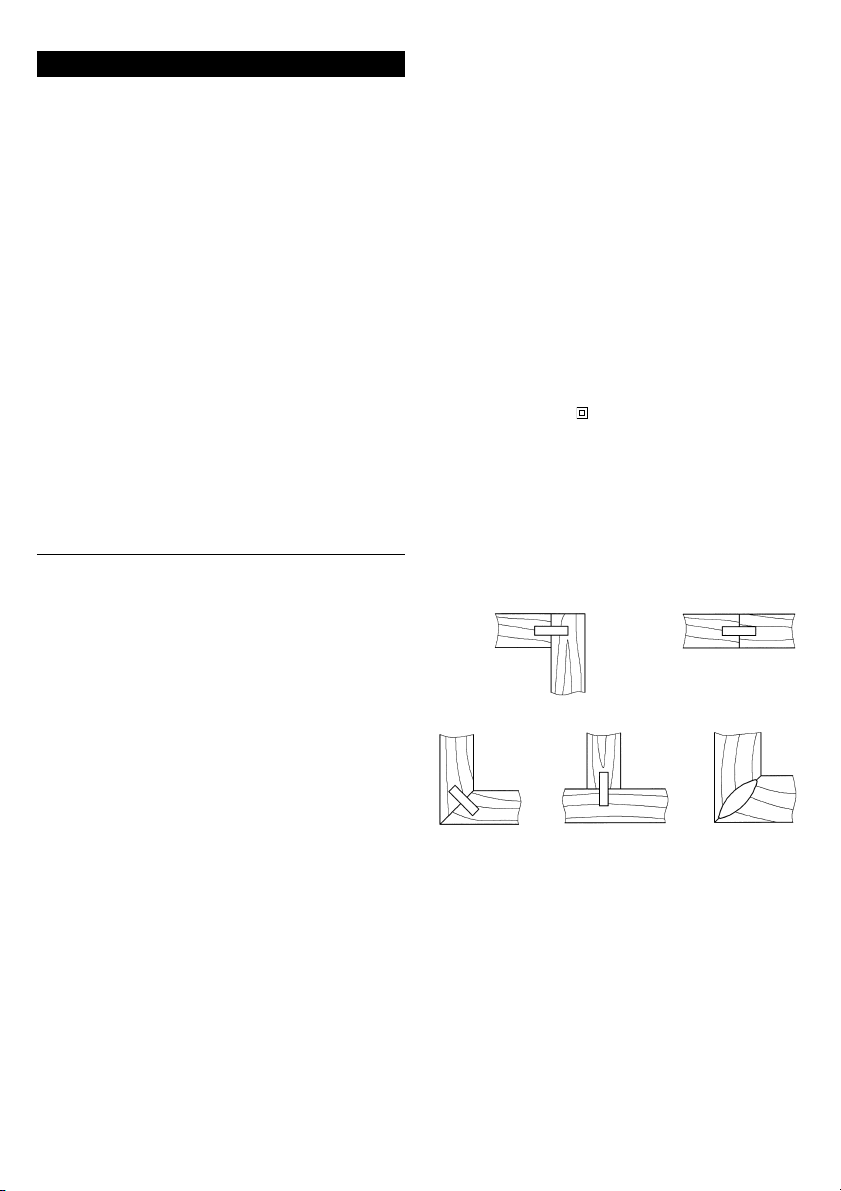
Suomi
1 Säätöpyörä
2 Kääntövaste
3 Asteikko
4 Oikeanpuoleinen pylväsohjaus
5 Merkintä
6 Kannatin
7 Pohjalevy
8 Kytkentärengas
9 Kippivipu
10 Etureuna
11 Kiertokahva
12 Kaarikahva
13 Moottorin kotelo
14 Ulosheittoputki
15 Lastupussi
16 Imuliitäntä
17 Verkkojohtomoduuli
18 Lukituspainike
19 Upotusruuvi
20 Painike
21 Kara
22 Laippamutteri
23 Jyrsin
24 Leikkuuhammas
25 Mutteri
26 Syvyysvaste
27 Revolverivaste
28 Kiinnityslaippa
29 Jyrsinsuojus
Tekniset tiedot 750 FDF
Tehonotto watteina 750
Antoteho watteina 400
Tyhjäkäyntikierrosluku min
-1
9800
Karakierre M10
Istukka Ø 22
Jyrsin-Ø maks. mm 100
Jyrsinterän-/Navan paksuus 4/3
Leikkuusyvyys mm 19
Kääntöalue ° 0–90
Paino n. kg 3,2
Käyttö
Tasovaarnajyrsintä 750 FDF voidaan käyttää kolojen jyrsimiseen kokopuuhun, vaneriin, lastulevyyyn, kuitulevyyn,
plexilasiin ja tekomarmoriin simplex- ja duplex-vaarnoja
nro 0, 10, 20, S6, H9 varten sekä kokopuun pihkareikien
jyrsimiseen.
Turvallisuus- ja käyttöohjeet, jotka on syytä lukea läpi
ennen koneen käyttöönottoa ja joiden noudattamista
ehdottomasti suosittelemme:
1. Ennen koneella suoritettavia töitä on verkkopistoke
irrotettava pistorasiasta. Tämä on tärkeää etenkin
ennen jyrsimen tai muiden työkalujen paikalleen
kiinnittämistä tai ennen koneen huoltoa.
2. Työkappale on kiinnitettävä tukevasti paikalleen.
3. Pidä huolta siitä, että jyrsinterät ovat teräviä. Tylsät
työkalut saavat aikaan huonon työtuloksen ja
kuormittavat tarpeettomasti moottoria.
4. Pidä huolta siitä, että moottori on sammutettu en-
nen koneen syrjään asettamista.
5. Jos laitetta ei käytetä pitkään aikaan, on parasta
irrottaa verkkopistoke pistorasiasta, jotta laite ei
epähuomiossa käynnisty!
6. Käytä ainoastaan jyrsimiä, jotka on tarkoitettu
käsiohjaukseen.
7. Tasovaarnajyrsimen 750 FDF moottorin on toimit-
tava moitteettomasti (kevyt käynti).
8. Kannatinta ei saa kiinittää, kun jyrsin on käynnissä.
9. Käytä aina suojalaseja ja kuulosuojaa.
10. Käytä aina ulosheittoputkea tai ulosheittoliitäntää.
11. Ohjaa konetta aina kahdella kädellä, kahvasta ja
moottorikotelosta kiinni pitäen.
12. Käytä konetta ainoastaan käyttöohjeessa ilmoitettuun käyttötarkoitukseen.
13. Molempien kääntövasteen kiertokahvojen (11) täytyy olla jyrsittäessä tukevasti kiinnitetyt.
14. Ulkona olevien pistokkeiden tulee olla suojattuja vikavirtakytkennällä (FI-).
15. Koteloa ei saa porata koneen merkitsemiseksi.
Suojaeristys vahingoittuu. Käytä tarroja.
16. Aseta johto aina niin, että se kulkee koneesta taaksepäin.
Turvallisuusohjeet ja tapaturmantorjunta
Ennen kuin otat koneen käyttöön, lue käyttöohje kokonaan
läpi, noudata tämän käyttöohjeen turvallisuusohjeita sekä
mukana olevan vihkosen yleisiä sähkötyökalujen turvalli-
suusohjeita.
Kaksinkertainen eristys
Laitteemme on käyttäjän optimaalista turvallisuutta ajatellen valmistettu Euroopan Unionin määräysten (EN-normien)
mukaisesti. Kaksinkertaisesti eristetyissä koneissa on aina
kansainvälinen merkki . Koneiden ei tarvitse olla maadoitettuja. Kaksijohtiminen johto riittää.
Laitteet on häiriösuojattu EN 55014 mukaisesti.
Käyttöönotto
Tarkasta ennen käyttöönottoa, vastaako verkkojännite laitteen tyyppikilvessä ilmoitettua arvoa.
Liitäntätyypit
Tasovaarnajyrsimellä 750 FDF voidaan valmistaa seuraavat
liitäntätyypit materiaaleilla puu, vaneri, lastulevy, kuitulevy,
pleksilasi ja tekomarmori.
Vaarnakoon valinta
Mater. vahvuus Vaarnakoko Mitat
8–12 0 47 x 15 x 4 mm
12–15 10 53 x 19 x 4 mm
>15 20 56 x 23 x 4 mm
Jotta liitäntä olisi mahdollisimman tukeva, käyttöön on aina
otettava mahdollisimman suuri vaarna. Kun materiaalin
vahvuus on yli 25 mm, voidaan käyttää 2 vaarnaa päällekkäin.
Kulmaliitos
Pitkittäis- ja
poikittaisliitos
Keskiseinäliitos
Viistoliitos
Kehysliitos
Page 33

Jyrsinsyvyyden säätö
Jyrsinsyvyys säädetään säätöpyörällä (1) valitun vaarnan
mukaan.
Vaarna Säätö Jyrsinsyvyys
Nro 0 0 8,0 mm
Nro 10 10 10,0 mm
Nro 20 20 12,3 mm
simplex S 13,0 mm
duplex D 14,7 mm
maksimi maks. 19,0 mm
Huomio! Onnettomuusvaara
● Kiinnitä jyrsinsuoja (29) aina työn ajaksi.
Kolon korkeuden säätö kääntövasteella 90°
Kolon korkeus voidaan säätää kääntövasteen (2) ja oikeanpuoleisessa pylväsohjauksessa olevan asteikon (3) avulla
tarkalleen materiaaliin paksuuden mukaisesti. Tällöin pitää
jyrsinsuojan (29) olla kiinnitettynä kääntövasteessa (2), ainoastaan 0°-asennossa (väliseinäliitoksissa) jyrsinsuoja
(29) on poistettava. Revolverivasteella (27) voidaan tehdä
säätö 3 materiaalipaksuudelle. Valmistajan tekemä säätö
on 16, 19 ja 25 mm paksuisille levyille.
Kolon korkeuden säätö kääntövasteella 0°–90°
Kolon korkeus voidaan säätää kääntövasteella (2). Kolon
tarkka korkeus on selvitettävä kokeilemalla. Tällöin tulee
jyrsinsuojan (29) olla kiinnitettynä (2) kääntövasteessa. Revolverivasteella (27) voidaan valita säätö 3 materiaalipaksuudelle. 6kt-mutteri on avataan, 6kt-ruuvi säädetään halutulle mitalle ja mutteri kiristetään uudelleen.
Lastuaukko ja imentä
Oheisina lisävarusteina pakkauksessa ovat ulosheittoputki
(14), lastupussi (15) ja imuliittimet (16). Ulosheittoputki (14)
tai imuliittimet (16) voidaan kiinnittää kannattimeen (6).
Näin lastut eivät lennä suoraan taaksepäin, vaan sivulle.
Lastupussi (15) voidaan laittaa imuliitäntöjen (16) päälle.
Näin lastut lentävät suoraan lastupussiin (15). Suositeltavaa on työskenneltäessä kiinnittää laitteeseen pölynimuri.
Joissakin maissa laitteeseen täytyy kiinnittää pölynimuri
tammea ja pyökkiä jyrsittäessä.
Koneen päälle- ja poiskytkentä
Kone käynnistetään kytkinrengasta (8) nuolen suuntaan
kiertämällä. Kiertoalueen lopussa kippivipu (9) lukkiutuu
automaattisesti paikalleen. Kippivivun ulospäin kallistunutta etureunaa (10) painamalla se vapautuu ja kytkinrengas (8) palaa automaattisesti takaisin lähtöasentoon. Kone
pysähtyy.
Kolovälien merkintä
Tavallisesti kolovälit valitaan väliltä 10 ja 15 cm. Ensimmäisen kolon keskikohdan tulisi olla 4–6 cm päässä työkappaleen reunasta. On suositeltavaa merkitä kolojen keskikohta
työkappaleelle. Kapeilla työkappaleilla kolot voidaan jyrsiä
suoraan kannattimen (6) merkintöjen (5), kääntövasteen (2)
tai pohjalevyn (7) avulla.
Huomio! Onnettomuusvaara
● Käytä suojalaseja ja kuulosuojaa.
● Ohjaa konetta aina kaksikätisesti kahvasta ja moot-
torikotelosta kiinnipitäen.
● Älä suuntaa jyrsinaukkoa kasvoja kohti, kun kone
on käynnissä.
● Älä vie kättä ulostuloaukkoon, kun kone käy.
● Irrota pistoke pistorasiasta, kun lastut täytyy pois-
taa.
● Älä vie kättä jyrsimen työskentelyalueelle.
Kolojen jyrsintä
Kolojen jyrsintä suoritetaan seuraavalla tavalla: Tasovaarnajyrsin 750 FDF asetetaan kannattimen (6) keskimerkinnän (5) avulla aiemmin työkappaleelle merkittyjen merkkien kohdalle. Viisteliitännöillä täytyy lisäksi säätää korkeus- ja kulma-asento molempien kiertokahvojen (11) ja
kääntövasteen (2) avulla. Kone käynnistetään. Kolo jyrsitään, työntämällä tasovaarnajyrsimen 750 FDF moottoriosa etukäteen valittuun vasteeseen saakka. Konetta ohjataan molemmin käsin, pitäen kiinni kaarikahvasta (12) ja
moottorin kotelosta (13) takaa. Kun eteenpäinvientipaine
laskee, moottoriosa vedetään automaattisesti takaisin
lähtöasentoon. Kapeilla työkappaleilla, joihin jyrsitään vain
1 tai 2 koloa, voidaan urien paikka valita kannattimen (6)
merkintöjen (5) avulla.
Liimaus ja pingotus
Työkappaleen koloihin laitetaan liimaa. Sen jälkeen vaarnat
laitetaan koloihin ja kappaleet liitetään yhteen. Jotta aikaan
saadaan tukeva liitäntä, täytyy kappaleet tämän jälkeen
pingottaa tiukasti toisiaan vasten ruuvipuristimen tms.
avulla.
Eri liitostyyppien jyrsintä
Kulmaliitos:
● Jyrsinsuoja (29) kiinnitettynä
● Korkeus säädetään portaattomasti oikeanpuoleisessa
pylväsohjauksessa (4) olevalla asteikolla (3).
● Korkeus esisäädetään revolverivasteella (27).
Viistoliitos:
● Jyrsinsuoja kiinnitettynä (29)
● Käytä säädettävää kääntövastetta (2)
Kehysliitos:
● Jyrsinsuoja kiinnitetttynä (29)
● Kahdella vaarnalla, kun levyn paksuus on yli 25 mm
● Normaali laitesäätö ja kierretty kääntökappale toisellle
jyrsinkololle
● Kääntövaste (2) vaihtelevalle reunavälille ja kierretty
työkappale toiselle jyrsinkololle
Keskiseinäliitos:
Vaakasuorassa asennossa, kääntövaste 90°
● Jyrsinsuoja (29) kiinnitettynä,
pystysuorassa asennossa, kääntövaste 0°
● Ilman jyrsinsuojan (29) kiinnitystä
Pitkittäis- ja poikittaisliitos:
Vaakasuorassa asennossa, kääntövaste 90°
● Jyrsinsuoja (29) kiinnitettynä
● Kääntövaste (2) vaihtelevalle reunavälille
Puun hartsireikien jyrsintä
Tämä työ voidaan suorittaa erikoisjyrsimellä (erikoisvaruste). Ensikäytöllä täytyy kannattimen (6) raon leveys jyrsiä
ensin vapaasti. Tämä tapahtuu painamalla erikoisen hartsireikäjyrsimen maksimiin jyrsinsyvyysvasteeseen asti eteen
ja jyrsimällä siten vaaditun aukon kannattimeen (6).
Erityisvaarnat
Vaarna S6
Jos liitettävien levyjen paksuus on yli 30 mm kuten esim.
ovenkehykset, portaat tai sängynrungot, on suositeltavaa
käyttää vaarnaa S6. Toimi tätä varten seuraavalla tavalla:
Säädä jyrsinsyvyys säätöpyörällä (1) maksimiin ja jyrsi kolo
kuten normaalivaarnoilla. Tämän jälkeen tasovaarnajyrsintä
750 FDF siirretään 10 mm ja jyrsin upotetaan vielä kerran
materiaaliin.
Vaarna H9
Kehysliitoksiin ja ohuille materiaaleille on suositeltavaa
käyttää vaarnaa H9. Tämän vaarnan työstöä varten laitteeseen on kiinnitettävä erikoisjyrsin (erikoisvaruste).
3
2
1
Page 34

Huomio!
Ennen työkalun paikalleen asettamista täytyy verkkopistoke ensin irrottaa ja verkkojohtomoduuli (17)
poistaa kotelosta lukituspainikkeella (18).
Jyrsimen vaihto
Kun jyrsin vaihdetaan, pohjalevyssä (7) olevat 4 upotusruuvia (19) irrotetaan ja otetaan pois kannattimesta (6). Painamalla painikettta (20) lukitetaan kara (21). Mutteri (22) irrotetaan kaksireikäpäisellä mutteriavaimella. Vanha jyrsin (23)
irrotetaan. Uusi jyrsin keskiöidään kiinnityslaippaan (28) ja
kiinnitetään mutterilla (22). Sen jälkeen pohjalevy asetetaan
uudelleen paikalleen.
Huomio!
Ota jyrsimen kiertosuunta huomioon.
Jyrsintäsyvyys on tarkastettava ja säädettävä mahdollisesti
uudelleen.
Jyrsintäsyvyyden säätö
Jyrsinsyvyys säädetään asettamalla säätöpyörällä (1) maksimiasennon. Työnnä tasovaarnajyrsimen moottoriosa sen
jälkeen vasteeseen asti eteen. Kierrä jyrsintä (23) tämän jälkeen niin pitkälle, että yksi leikkuuhammas (24) saavuttaa
kehän etummaisen kohdan. Voit nyt mitata jyrsinsyvyyden
viivottimella jyrsimestä (23). Irrota syvyysvasteen (26)
mutteri (25) jyrsinsyvyyden korjaamista varten. Voit säätää
jyrsinsyvyyden uudelleen kiertämällä syvyysvastetta (26)
(1 kierros = 0,7 mm). Säätö lukkiutuu, kun kiristät mutterin
(25).
Hiiliharjojen vaihto
Valtuutettu huoltoliikkemme suorittaa tämän kuten kaikki
muutkin huoltotyöt nopeasti ja asiantuntemuksella.
Verkkojohto
Vaurioituneita verkkojohtoja ei saa käyttää. Ne on vaihdettava välittömästi uusiin.
Uuden verkkojohtoyksikön (17) ansiosta vaihto on hyvin
yksinkertaista. Paina lukituspainikkeita (18) ja irrota verkkojohtoyksikkö (17) kotelosta. Aseta uusi verkkojohtoyksikkö koteloon ja paina paikalleen niin, että se lukittuu. Erikoisvarusteena on saatavissa eri pituisia verkkojohtoja.
Yhdistä verkkojohtoyksikköön vain KRESS-sähkötyökaluja! Älä yritä käyttää sillä muita sähkölaitteita!
Moottori, puhdistus, hoito
Laitteen voimakkaalla yleismoottorilla on suuret voimareservit. Moottorin käyttöikä pitenee, jos puhallat pölyn puhaltimesta aina käytön jälkeen. Tuuletusaukot täytyy pitää
aina puhtaina, sillä tasainen ilmanvaihto on tärkeää. Kone
on kestovoideltu, eikä tarvitse mitään erityistä huoltoa.
Työkalujen hoito
Käytä ainoastaan teräviä ja moitteettomassa kunnossa olevia työkaluja. Näin säästät moottoria ja koneen käyttöikä
pitenee. Kovametallisia jyrsimiä on käsiteltävä erityisen varovaisesti, sillä terät halkeavat helposti. Vioittuneita jyrsimiä
ei saa käyttää.
Melua ja tärinää koskevat tiedot
Mittausarvot EN 50144 mukaisesti mitattuna.
Äänenpainetaso
= 79,5+3dB (A)
Äänentehotaso = 92,5
+3
dB (A)
Työpaikan
emissioarvo = 82,5
+3
dB (A).
Käyttö edellyttää meluntorjuntatoimenpiteitä.
Arvioitu kiihdytys on tavallisesti alle 2,5 m/s
2
.
Erikoisvarusteet
Jyrsin vaarnalle H9
Jyrsin puun hartsireikien jyrsintään
Ympäristönsuojelu
Kress ottaa käytöstä poistetut koneet takaisin resursseja
säästäväänkierrätykseen. Moduulirakenteensa vuoksi Kresskoneet voidaan hyvin helposti purkaa uudeelleen käytettäviin perusosiiin. Luovuta käytöstä poistettu Kress-kone
kauppaan takaisin tai lähetä se suoraan Kressille.
Oiheus muutokslin pidätetään.
4
Page 35

Eλληνικά
1 Ροδέλα ρύθµισησ
2 Περιστρεφµενοσ οδηγσ
3 Kλίµακα
4 Oδήγηση κολώνασ δεξιά
5 Eνδειξη
6 Φορέασ
7 Πλάκα
8 ∆ακτύλιοσ λειτουργίασ
9 ∆ιακπτησ
10 Eµπρσθια άκρη
11 Περιστρεφµενη λαβή
12 Λαβή
13 Σώµα κινητήρα
14 Σωλήνασ εξαγωγήσ
15 Σάκοσ περισυλλογήσ
16 Στµιο αναρρφησησ
17 Mονάδα καλωδίου
18 Πλήκτρο µανδάλωσησ
19 Bίδα
20 Πλήκτρο
21 Aτρακτοσ
22 Kολλαρωτ παξιµάδι
23 Φρέζα
24 ∆ντι κοπήσ
25 Παξιµάδι
26 Oδηγσ βάθουσ
27 Περιστρεφµενοσ οδηγσ τύπου ρεβλβερ
28 Φλάντζα σύσφιγξησ
29 Oδηγσ προστασίασ φρεζαρίσµατοσ
Tεχνικά χαρακτηριστικά 750 FDF
Oνοµαστική ισχύς Watt 750
Iσχύς απδοσης σε Watt 400
Στροφές χωρίς φορτίο min
-1
9800
Σπείρωµα ατράκτου M10
Yποδοχή 22
Φρεζ.- max. σε mm 100
Φύλλο φρεζ.-/Πάχος µουαγιέ 4/3
Bάθος κοπής mm 19
Περιοχή περιστροφής σε ° 0–90
Bάρος περ. kg 3,2
Eφαρµογέσ
H Kαβιλιέρα 750 FDF εφαρµζεται για το φρεζάρισµα
εγκοπών σε διάφορα υλικά µασίφ ξύλο, νοβοπάν,
κντρα-πλακέ, πλάκες ινών, πλέξιγκλας και συνθετικ
µάρµαρο για τους τύπους καβίλιας αριθµ. 0, 10, 20, S6,
H9, Simplex και Duplex καθώς και φρεζάρισµα ρητινωδών υλικών σε ξύλο µασίφ.
Oροι ασφαλείασ και υποδείξεισ, που πρέπει να
διαβαστούν οπωσδήποτε πριν την έναρξη λειτουργίασ
και να τηρηθούν αυστηρά:
1. Πριν τη διεξαγωγή οποιωνδήποτε εργασιών στη
µηχανή βγάζετε το καλώδιο απ την πρίζα. Aυτ
ισχύει κυρίωσ για την τοποθέτηση των φρεζών ή
άλλων εργαλείων και για εργασίεσ σέρβισ.
2. Στερεώστε αν είναι δυνατν το προσ επεξεργασία
εργαλείο.
3. Προσέχετε να είναι οι φρέζεσ σε καλή κατάσταση.
Eργαλεία που δεν κβουν καλά έχουν σαν
αποτέλεσµα χι καθαρή εργασία και περιττή
υπερφρτωση του κινητήρα.
4. Oταν βάζετε στην άκρη την καβιλιέρα προσέχετε
να βρίσκεται εκτσ λειτουργίασ.
5. Για να αποφύγετε τυχν αθέλητη εκκίνηση του
εργαλείου σε περίπτωση µακράσ διακοπήσ τησ
εργασίασ βγάζετε το καλώδιο απ την πρίζα!
6. Xρησιµοποιείτε µνο φρέζεσ για χειροκίνητη
ώθηση.
7. O κινητήρασ τησ καβιλιέρασ 750 FDF πρέπει να
λειτουργεί χωρίσ να µπλοκάρει.
8. O φορέασ δεν πρέπει να είναι µπλοκαρισµένοσ
ταν έχει βγει η φρέζα.
9. Eργάζεσθε πάντα φορώντασ προστατευτικά γιαλιά
και ωτασπίδεσ.
10. Xρησιµοποιείτε πάντα τον σωλήνα ή το στµιο
εξαγωγήσ πριονιδιών.
11. Oδηγείτε το εργαλείο πάντα µε τα δυο χέρια απ
τη λαβή και το σώµα τησ µηχανήσ.
12. Xρησιµοποιείτε τη µηχανή µνο για τισ εργασίεσ
που περιγράφονται στισ οδηγίεσ χρήσησ.
13. Oι δυο λαβέσ (11) του περιστρεφµενου οδηγού
πρέπει να είναι σφιγµένεσ καλά κατά το
φρεζάρισµα.
14. Eξωτερικέσ πρίζεσ πρέπει να διαθέτουν ασφάλεια
προστασίασ λανθασµένου ρεύµατοσ (FI-).
15. Για τη σήµανση τησ µηχανήσ µην τρυπάτε το
περίβληµα τησ. Eτσι υπεργεφυρώνεται η προστατευτική µνωση. Xρησιµοποιείτε αυτοκλλητεσ
ετικέτεσ.
16. Oδηγείτε το καλώδιο πάντα πίσω απ τη µηχανή.
Yποδείξεισ ασφαλείασ και προστασία απ ατυχήµατα
Πριν θέσετε τη µηχανή σε λειτουργία διαβάστε τις
οδηγίες χρήσης, τηρήστε τις υποδείξεισ ασφαλείασ
των οδηγιών αυτών καθώς και τις Γενικές Yποδείξεισ
ασφαλείασ για ηλεκτρικά εργαλεία στο φυλλάδιο που
συνοδεύει το εργαλείο.
∆ιπλή µνωση
Oι συσκευές µας είναι κατασκευασµένες για να
προσφέρουν την σο το δυνατή µεγαλύτερη ασφάλεια
στον χειριστή, σύµφωνα µε τις Eυρωπαϊκές
Προδιαγραφές. ∆ιπλά µονωµένες µηχανές φέρουν το
διεθνές σήµα . Oι µηχανές δεν πρέπει να είναι
γειωµένες. Eπαρκεί ένα δίκλωνο καλώδιο.
Oι µηχανές φέρουν αντιπαρασιτική προστασία
σύµφωνα µε τις προδιαγραφές EN 55014.
Eναρξη λειτουργίασ
Πριν συνδέσετε τη µηχανή σας µε το ηλεκτρικ ρεύµα,
ελέγξτε αν η τάση του ηλεκτρικού σας δικτύου
συµφωνεί µε την τάση δικτύου που αναφέρεται στην
πλακέτα της συσκευής!
Eίδη σύνδεσησ
Mε την Kαβιλιέρα (Λαµέλο) 750 FDF µπορούν να
γίνουν συνδέσεις στα υλικά µασίφ ξύλο, κντραπλακέ, νοβοπάν, πλάκες ινών, πλέξιγκλας και συνθετικ µάρµαρο.
Eπιλογή του µεγέθουσ πλακέ καβίλιασ
Πάχος υλικού Mέγεθος καβίλιας ∆ιαστάσεις
8–12 0 47 x 15 x 4 mm
12–15 10 53 x 19 x 4 mm
>15 20 56 x 23 x 4 mm
Γωνιακή ένωση
Oριζντια και
κάθετη ένωση
Eνωση εσωτερικού
τοιχώµατος
Eνωση µε φάλτσα Eνωση πλαισίων
Page 36

Για µια ιδανική σύνδεση πρέπει να χρησιµοποιείτε τη
µεγαλύτερηδυνατή καβίλια. Για πάχος υλικού πάνω
απ 25 mm µπορείτε να χρησιµοποιήσετε 2 καβίλιες.
Ρύθµιση βάθουσ
H ρύθµιση βάθους διεξάγεται µε τη ροδέλα ρύθµισης
(1) ανάλογα µε την καβίλια που επιλέξατε.
Bάθος
Kαβίλια Ρύθµιση φρεζαρίσµατος
Nr. 0 0 8,0 mm
Nr. 10 10 10,0 mm
Nr. 20 20 12,3 mm
Simplex S 13,0 mm
Duplex D 14,7 mm
maximal max. 19,0 mm
Προσοχή! Kίνδυνοσ ατυχήµατοσ
• Eργάζεσθε πάντα µε εφαρµοσµένο οδηγ προστα-
σίασ φρεζαρίσµατοσ (29)
Ρύθµιση µήκουσ εγκοπήσ µε περιστρεφµενο οδηγ
90Γ
Tο µήκος εγκοπής µπορεί να ρυθµιστεί µε τον
ρυθµιζµενο περιστρεφµενο οδηγ (2) και την κλίµακα (3) στην οδήγηση κολώνας δεξιά ανάλογα µε το
πάχος υλικού. O οδηγς προστασίας φρεζαρίσµατος
(29) πρέπει να είναι εφαρµοσµένος στον περιστρεφµενο οδηγ (2), εκτς απ τη θέση 0Γ (για ενώσεις
εσωτερικού τοιχώµατος) που ο οδηγς προστασίας
φρεζαρίσµατος (29) αφαιρείται. Mε τη βοήθεια του
περιστρεφµενου οδηγού τύπου ρεβλβερ (27) µπορούν να προεπιλεχθούν 3 πάχη υλικού. Aπ το
εργοστάσιο έχει γίνει προρύθµιση για τα πάχη 16, 19
και 25 mm.
Ρύθµιση µήκουσ εγκοπήσ µε περιστρεφµενο οδηγ
0Γ–90Γ
Tο µήκος εγκοπής µπορεί να ρυθµιστεί µε τον ρυθµιζµενο περιστρεφµενο οδηγ (2). Tο ακριβές µήκος
της εγκοπής πρέπει να καθοριστεί µετά απ δοκιµές.
O οδηγς προστασίας φρεζαρίσµατος (29) πρέπει να
είναι εφαρµοσµένος στον περιστρεφµενο οδηγ (2).
Mε τη βοήθεια του περιστρεφµενου οδηγού τύπου
ρεβλβερ (27) µπορούν να προεπιλεχθούν 3 πάχη
υλικού. Πρέπει να λασκάρετε το εξαγωνικ παξιµάδι ,
να ρυθµίσετε την εξαγωνική βίδα στο πάχος που επιθυµείτε και να ξανασφίξετε το παξιµάδι.
Eξαγωγή πριονιδιών και αναρρφηση
Στη συσκευασία περιέχονται σαν εξαρτήµατα ένας
σωλήνας εξαγωγής πριονιδιών (14), ένας σάκος
περισυλλογής πριονιδιών (15) και ένα στµιο
αναρρφησης (16). O σωλήνας εξαγωγής (14) ή το
στµιο αναρρφησης (16) µπορούν να στερεωθούν
στον φορέα (6). Mε αυτν τον τρπο τα πριονίδια δεν
εκτοξεύονται προς τα πίσω αλλά πλάγια. O σάκος
περισυλλογής (15) µπορεί να τοποθετηθεί στο στµιο
αναρρφησης (16). Eτσι τα πριονίδια οδηγούνται
κατευθείαν στον σάκο περισυλλογής (15). Σε περίπτωση µνιµης εγκατάστασης συνιστούµε την σύνδεση
ενς κοινού απορροφητήρα. Σε µερικές χώρες πρέπει
κατά το φρεζάρισµα ξύλου βαλανιδιάς και οξυάς να
προσαρµοστεί απορροφητήρας,
Eναρξη και ακινητοποίηση µηχανήσ
Γυρνώντας τον δακτύλιο (8) προς την κατεύθυνση του
βέλους τίθεται η µηχανή σε λειτουργία. Στο τέλος της
περιοχής περιστροφής µανδαλώνει ο µοχλς (9)
αυτµατα. Πιέζοντας την εµπρσθια άκρη (10) του
µοχλού (9) αυτς απελευθερώνεται και ο δακτύλιος
λειτουργίας (8) επιστρέφει αυτµατα στην αρχική
θέση. H µηχανή ακινητοποιείται.
Xάραξη αποστάσεων εγκοπών
Kατά καννα οι αποστάσεις των εγξοπών πρέπει να
κυµαίνονται µεταξύ 10 και 15 cm. Tο κέντρο της
πρώτης εγκοπής πρέπει να βρίσκεται περίπου 4–6 cm
απ την εξωτερική άκρη του τεµαχίου. Συνιστάται να
χαράζετε το κέντρο της εγκοπής στο προς επεξεργασία τεµάχιο. Σε λεπτά τεµάχια οι εγκοπές µπορούν να
γίνουν κατευθείαν µε τη βοήθεια σηµαδιών (5) στον
φορέα (6), τον περιστρεφµενο οδηγ (2) ή στην
πλάκα (7).
Προσοχή! Kίνδυνοσ ατυχήµατοσ
● Φοράτε προστατευτικά γιαλιά και ωτασπίδεσ.
● Oδηγείτε το εργαλείο µε τα δύο χέρια πιάνοντασ
τη λαβή και το σώµα του εργαλείου.
● Oσο λειτουργεί το εργαλείο µην κατευθύνετε το
άνοιγµα τησ φρέζασ στο πρσωπο.
● Oσο λειτουργεί η µηχανή µην απλώνετε το χέρι
σασ στο άνοιγµα εξαγωγήσ πριονιδιών.
● Bγάζετε το καλώδιο απ την πρίζα ταν πρκειται
να αφαιρέσετε πριονίδια.
● Mην απλώνετε το χέρι σασ στην περιοχή τησ
κοπήσ.
Φρεζάρισµα των εγκοπών
Για το φρεζάρισµα των εγκοπών ακολουθούνται τα
εξής βήµατα: Tοποθετείτε την καβιλιέρα 750 FDF µε
την ένδειξη κεντραρίσµατος (5) στον φορέα (6) πάνω
στο υλικ που έχετε προηγουµένως σηµαδέψει. Σε
περίπτωση γωνιακών ενώσεων πρέπει ρυθµίσετε
επιπλέον το ύψος και τη γωνία µε τη βοήθεια των δυο
περιστρεφοµένων λαβών (11) και του περιστ-ρεφοµένου οδηγού (2). H µηχανή τίθεται σε λειτουργία. H
εγκοπή φρεζάρεται σπρώχνοντας το σώµα της µηχανής της καβιλιέρας 750 FDF µέχρι το προεπιλεγµένο
στοπ. Πρέπει να κρατάτε το εργαλείο και µε τα δυο
χέρια, στη λαβή (12) και στο σώµα του κινητήρα (13).
Oταν µειωθεί η πίεση ώθησης το σώµα του κινητήρα
επιστρέφει αυτµατα στην αρχική θέση. Σε λεπτά υλικά, που πρέπει να φρεζαριστούν µνο 1 ή 2 εγκοπές,
µπορείτε να επιλέξετε τη θέση των εγκοπών µε τη
βοήθεια των ενδείξεων (5) στο φορέα (6).
Kλληµα και σύσφιξη
Στις εγκοπές στο υλικ αλείφετε κλλα. Mετά
τοποθετείτε τις πλακέ καβίλιες στις εγκοπές και
ενώνετε τα υλικά. Για να επιτύχετε µια καλή σλυνδεση
συσφίγγετε τα υλικά µε κατάλληλα εργαλεία.
Φρεζάρισµα των διαφορετικών τύπων σύνδεσησ
Γωνιακή ένωση:
● µε εφαρµοσµένο οδηγ προστασίας φρεζαρίσµατος
(29)
● µε ρύθµιση ύψους αδιαβάθµητα µέσω κλίµακας (3)
στον οδηγ κολώνας δεξιά (4)
● µε προρυθµισµένο ύψος στο σύστηµα περιστρε-
φµενου οδηγού (27)
Eνωση µε φάλτσα:
● µε εφαρµοσµένο οδηγ προστασίας φρεζαρίσµατος
(29)
● µε ρυθµιζµενο περιστρεφµενο οδηγ (2)
Eνωση πλαισίων:
● µε εφαρµοσµένο οδηγ προστασίας φρεζαρίσµατος
(29)
● µε 2 πλακέ καβίλιες για πάχος υλικού πάνω απ
25 mm
● µε κανονική ρύθµιση εργαλείου και γυρισµένο
υλικ για τη δεύτερη εγκοπή
● µε περιστρεφµενο οδηγ (2) για µεταβλητή
απσταση περιθωρίου και γυρισµένο υλικ για τη
δεύτερη εγκοπή
3
2
1
Page 37

Eνωση εσωτερικού τοιχώµατοσ:
σε οριζντια εφαρµογή µε περιστρεφµενο οδηγ 90Γ
● µε εφαρµοσµένο οδηγ προστασίας φρεζαρίσµατος
(29)
σε κάθετη εφαρµογή µε περιστρεφµενο οδηγ 0Γ
● χωρίς εφαρµοσµένο οδηγ προστασίας φρεζα-
ρίσµατος (29)
Oριζντια και κάθετη ένωση:
σε οριζντια εφαρµογή µε περιστρεφµενο οδηγ 90Γ
● µε εφαρµοσµένο οδηγ προστασίας φρεζαρίσµατος
(29)
● µε περιστρεφµενο οδηγ (2) για µεταβλητή
απσταση περιθωρίου
Φρεζάρισµα ρητινωδών υλικών
Tο φρεζάρισµα διεξάγεται µε ειδική φρέζα (ειδικ
εξάρτηµα). Kατά την πρώτη χρήση πρέπει να φρεζαριστεί η εγκοπή στον φορέα (6). Aυτ γίνεται
πιέζοντας την ειδική φρέζα προς τα µπροστά έως το
βαθύτερο σηµείο του οδηγού βάθους, έτσι ώστε να
φρεζάρει στο φορέα (6) την εγκοπή που επιθυµείτε.
Eιδικέσ καβίλιεσ πλακέ
Kαβίλια S6
Για συνδέσεις µε πάχος υλικού µεγαλύτερο απ
30 mm πως π.χ. πλαίσια πορτών, σκάλες ή πλαίσια
κρεβατιών συνιστάται η χρήση της καβίλιας S6. Πρέπει
να ακολουθήσετε τα εξής βήµατα. Ρυθµίστε το βάθος
φρεζαρίσµατος στη ροδέλα ρύθµισης (1) στο max. και
φρεζάρετε την εγκοπή πως για κανονικές καβίλιες.
Mετά µετακινήστε την καβιλιέρα 750 FDF κατά 10 mm
και ξαβαβυθίστε τη λάµα.
Kαβίλια H9
Για συνδέσεις πλαισίων και για λεπτά υλικά συνιστάται
η χρήση της καβίλιας H9. Γι‘ αυτή την καβίλια πρέπει
να εφαρµζεται ειδική φρέζα (ειδικ εξάρτηµα).
Προσοχή!
Πριν την τοποθέτηση των εργαλείων βγάζετε πάντα το
καλώδιο απ την πρίζα ή αφαιρείτε τη µονάδα
καλωδίου (17) απ το σώµα τησ συσκευήσ πιέζοντασ τα
πλήκτρα µανδάλωσησ (18).
Aλλαγή φρέζασ
Για να αλλάξετε τη φρέζα πρέπει να ξεβιδώσετε τις 4
βίδες (19) στην πλάκα σώµατος (7) και να αφαιρεθούν
απ το πλαίσιο (6). Πιέζοντας το πλήκτρο (20)
µανδαλώνει η άτρακτος (21). Mε το κλειδί παξιµαδιών
µπορεί να ξεβιδωθεί το κολλαρωτ παξιµάδι (22). H
παλιά φρέζα (23) αφαιρείται. H νέα φρέζα κεντράρεται
στη φλάντζα σύσφιγξης (28) και σταθεροποιείται µε το
κολλαρωτ παξιµάδι (22). Mετά εφαρµζετε πάλι την
πλάκα.
Προσοχή!
Προσέχετε την κατεύθυνση περιστροφήσ τησ φρέζασ.
Tο βάθος φρεζαρίσµατος πρέπει να ελεγχθεί και εν
ανάγκη να επαναρυθµιστεί.
Ρύθµιση βάθουσ φρεζαρίσµατοσ
Για τη ρύθµιση του βάθους φρεζαρίσµατος επιλέξτε
στη ροδέλα ρύθµισης (1) τη θέση max. Mετά σπρώχνετε τη µηχανή προς τα µπροστά. Στρίψτε τη φρέζα (23)
µέχρι να φτάσει ένα δντι κοπής (24) το πιο εµπρσθιο
σηµείο. Mε µια κλίµακα µπορείτε να µετρήσετε το
βάθος στη φρέζα (23). Για να διορθώσετε το βάθος
φρεζαρίσµατος χαλαρώνετε το παξιµάδι (25) στον
οδηγ βάθους (26). Γυρίζοντας τον οδηγ βάθους (26)
(1 περιστροφή = 0,7 mm) µπορείτε να επαναρυθµίσετε
το βάθος φρεζαρίσµατος. Σφίγγοντας το παξιµάδι (25)
η ρύθµιση σταθεροποιείται.
Aντικατάσταση των ψηκτρών
Aυτή την εργασία και άλλες εργασίες σέρβις
διεξάγουν γρήγορα και σωστά τα εξουσιοδοτηµένα
συνεργεία µας.
Kαλώδιο
Φθαρµένα καλώδια δεν επιτρέπεται να χρησιµοποιούνται. Πρέπει να αντικαθιστώνται αµέσως.
Aυτ µπορεί να γίνει χάρι της µονάδας καλωδίου
ρεύµατος (17) µε τον πιο απλ τρπο. Πιέστε τα δυο
άγκιστρα µανδάλωσης (18) και τραβήξτε τη µονάδα
καλωδίου (17) απ τη λαβη. Tοποθετήστε τη νέα µονάδα
καλωδίου δτη λαβη και µανδαλώστε τη. Kαλώδια σε
διάφορα µήκµ υπάρχουν σαν ειδικ εξάρτηµα.
Xρησιµοποιείτε τη µονάδα καλωδίου µνο για τα
ηλεκτρικά εργαλεία τησ KRESS! Mην προσπαθήσετε
να λειτουργήσετε µε αυτήν άλλεσ ηλεκτρικέσ συσκευέσ.
Kινητήρασ, καθαρισµσ, φροντίδα
O κινητήρας της µηχανής έχει επαρκή αποθέµατα
ισχύος. O σταθερς εξαερισµς είναι σηµαντικς για
τη διάρκεια ζωής της µηχανής και γι΄ αυτ θα πρέπει
µετά απ κάθε χρήση να φυσάτε τη σκνη απ τον
εξαεριστήρα. Oι εγκοπές εξαερισµού πρέπει να είναι
πάντα ελεύθερες και καθαρές. H µηχανή είναι µνιµα
γρασαρισµένη και δεν χρειάζεται ιδιαίτερη συντήρηση.
Φροντίδα τω ν εργαλείων
Φροντίζετε να χρησιµοποιείτε φρέζες που βρίσκονται
σε καλή κατάσταση. Eτσι δεν επιβαρ·υνετε τον
κινητήρα και αυξάνετε τη διάρκεια ζ ωής της µηχανής.
Φρέζες σκληρού µετάλλου απαιτούν ιδιαίτερα
προσεκτική µεταχείριση, γιατί οι λάµες µπορούν να
σπάσουν εύκολα. Eλαττωµατικές φρέζες δεν πρέπει
να χρησιµοποιούνται πια.
Στοιχεία εκποµπήσ θορύβου και κραδασµών
∆ιεξαγωγή µέτ
ρησης σύµφωνα µε
EN 50144.
Στάθµη πίεσης ήχου
= 79,5+3dB (A)
Στάθµη απδοσης ήχου = 92,5
+3
dB (A)
Tιµή εκποµπής στη
θέση εργασίας = 82,5
+3
dB (A).
O χειριστής πρέπει να φορέσει προστατευτικές
ωτασπίδες.
H επιτάχυνση που µετρήθηκε είναι σύµφωνα µε τον
τύπο µικρτερη απ 2,5 m/s
2
.
Eιδικά εξαρτήµατα
Φρέζα για πλακέ καβίλια H9
Φρέζα για ρητινώδη υλικά
Προστασία περιβάλλοντοσ
H Kress δέχεται παροπλισµένες µηχανές για ανακύκλωση που σέβεται τους φυσικούς πρους. Λγω
της κατασκευής τους οι µηχανές Kress µπορούν να
αποσυναρµολογηθούν στα επαναξιοποιήσιµα βασικά
υλικά τους. Παραδστε την παροπλισµένη σας µηχανή
Kress στο κατάστηµα πώλησης ηλεκτρικών εργαλείων
ή αποστείλατε την κατευθείαν στην Kress.
∆ιατηρούµε το δικαίωµα αλλαγών.
4
Page 38
EN 50144-2-17, EN 50144-2-18, EN 55014-1, EN 55014-2, EN 61000-3-2,
EN 61000-3-3, 73/23/EWG, 89/336/EWG, 98/37/EG
Kress-elektrik GmbH + Co., D-72406 Bisingen
Bisingen, im Februar 2003
Page 39

Garantie
1. Dieses Elektrowerkzeug wurde mit hoher Präzision gefertigt
und unterliegt strengen werkseitigen Qualitätskontrollen.
2. Daher garantieren wir die kostenlose Beseitigung von
Fabrikations- oder Materialfehlern, die innerhalb von 24 Monaten
ab Verkaufsdatum an den Endverbraucher auftreten. Wir behalten
uns vor, defekte Teile auszubessern oder durch neue zu ersetzen.
Ausgetauschte Teile gehen in unser Eigentum über.
3. Unsachgemäße Verwendung oder Behandlung sowie die Öffnung
des Gerätes durch nicht autorisierte Reparaturstellen führen zum
Erlöschen der Garantie. Dem Verschleiß unterworfenen Teile sind
von Garantieleistungen ausgeschlossen.
4. Garantieansprüche können nur bei unverzüglicher Meldung von
Mängeln (auch bei Transportschäden) anerkannt werden. Durch
Ausführung von Garantieleistungen wird die Garantiezeit nicht
verlängert.
5. Bei Störungen bitte Gerät mit ausgefüllter Garantiekarte und
kurzer Mängelbeschreibung an uns oder die zuständige
Servicestelle einsenden. Kaufbeleg beifügen.
6. Durch die von uns übernommenen Garantie-Verpflichtungen
werden alle weitergehenden Ansprüche des Käufers –
insbesondere das Recht auf Wandelung, Minderung oder
Geltendmachung von Schadenersatzansprüchen –
ausgeschlossen.
7. Dem Käufer steht jedoch nach seiner Wahl das Recht auf
Minderung (Herabsetzung des Kaufpreises) oder Wandelung
(Rückgängigmachung des Kaufvertrages) zu, falls es uns nicht
gelingt, evtl. auftretende Mängel innerhalb einer angemessenen
Frist zu beseitigen.
8. Nicht ausgeschlossen sind die Schadensersatzansprüche nach
den §§ 463, 480 Abs. 2, 635 BGB wegen Fehlens zugesicherter
Eigenschaften.
9. Die Bestimmungen nach Punkt 7 und 8 gelten nur für den Bereich
der Bundesrepublik Deutschland.
Guarantee
1. This electrical tool has been designed with high precision and was
approved after undergoing strict quality control checks in the
factory.
2. We are therefore able to guarantee free servicing of any
production or material faults which arise in the 24 months after the
date of sale to the purchaser. We reserve the right to repair
defective parts or else replace them with new parts. Parts which
have been replaced become our property.
3. The guarantee will be rendered void if the device is used
improperly, mistreated or opened up by unauthorised repair
personnel. Parts which are subject to wear are not covered by the
guarantee.
4. The guarantee may only be enforced when defects are reported
without undue delay (including shipping damage). Guarantee
implementation does not extend the guarantee period.
5. If the tool is defective, please complete the guarantee card and
return the unit, guarantee card and a brief description of the
problem to the responsible service location. Please enclose your
sales receipt.
6. The guarantee obligations assumed by us shall exclude any
further claims on the part of the buyer, in particular the right to
recission of a sale, reduction and the assertion of damage claims.
7. However, the buyer shall have the right to either a reduction (in the
purchase price) or the recission of the sale (cancellation of the
sales agreement) should we fail to eliminate any defects within a
reasonable period of time.
8. Damage claims in accordance with §§ 463, 480 Paragraph 2,
635 BGB due to absence of guaranteed quality shall not be not
excluded.
9. The provisions defined in Items 7 and 8 only apply to the Federal
Republic of Germany.
Garantie
1. Cet outil électronique a été fabriqué avec une grande précision et
soumis à des contrôles de qualité sévères en usine.
2. C’est pourquoi nous garantissons au consommateur final,
l’élimination gratuite de défauts de fabrication ou de matière qui
surviendraient dans les 24 mois suivant la date d’achat. Nous
nous réservons le droit de réparer les pièces défectueuses ou de
les remplacer. Les pièces échangées font alors partie de notre
propriété.
3. L’utilisation ou la manipulation non conforme, de même que
l’ouverture de l’outil dans des ateliers de réparation non habilités,
entraînent la résiliation de la garantie. Les prestations de garantie
excluent l’usure des pièces soumises.
4. Les revendications de garantie ne pourront être prises en compte
qu'en cas de déclaration immédiate des défauts (avaries dues au
transport y comprises). L'exécution des prestations de garantie ne
donne pas droit à une prolongation de la période de validité de la
garantie.
5. En cas de dysfonctionnement, veuillez expédier l'appareil avec sa
carte de garantie dûment complétée et une brève description des
défauts à notre adresse ou à la station de service après-vente
concernée. Prière de joindre la facture.
6. Une prise en charge par nos soins dans le cadre de la garantie,
exclut tout autre recours de la part de l'acheteur, en particulier le
droit de rétraction, de réduction ou de revendication de
dommages-intérêts.
7. Cependant, il conserve son droit de rétraction (annulation du
contrat de vente) ou de réduction (abaissement du prix d'achat),
selon ses convenances, si nous ne sommes pas en mesure
d'éliminer d'éventuels défauts dans un délai convenable.
8. Ne sont pas exclues, les revendications de dommages-intérêts
selon §§ 463, 480 Al. 2, 635 du Code Civil allemand, relatives à
l'absence de propriétés garanties.
9. Les dispositions 7 et 8 ne sont valables que pour l'Allemagne.
Garantie
1. Dit elektrisch werktuig werd met de grootste precizie vervaardigd
en wordt in de fabriek aan strenge kwaliteitscontroles onderworpen.
2. Daarom garanderen wij de kosteloze herstelling van fabricage- of
materiaalfouten die binnen 24 maanden vanaf de verkoopsdatum
bij de eindverbruiker optreden. Wij hebben het recht defecte
onderdelen te herstellen of door nieuwe te vervangen. Vervangen
onderdelen worden opnieuw onze eigendom.
3. Ondeskundig gebruik of verkeerde behandeling alsook het openen
van de macine door niet-geautoriseerde hersteldiensten doen de
garantie vervallen. Aan slijtage onderhevige oderdelen zijn van de
garantieprestaties uitgesloten.
4. Er kan slechts aanspraak op garantie verleend worden als de
schade onverwijld gemeld werd (ook bij transportschade). Er volgt
geen verlenging van de garantieperiode na uitvoering van
garantieprestaties.
5. Gelieve in geval van storing de machine met ingevulde garantiebon en een korte beschrijving van de schade aan ons of aan een
bevoegde service-dienst in te sturen. Cassabon bijvoegen.
6. Door de door ons opgenomen garantieverplichtingen zijn alle
verdere aanspraken van de koper – met name het recht op
koopvernietiging, prijsreductie of het eisen van schadevergoeding
– uitgesloten.
7. De koper heeft echter naar keuze het recht op prijsreductie
(vermindering van de aankoopprijs) of op koopvernietiging
(annuleren van het koopcontract), indien wij er niet in slagen,
eventueel opgetreden defecten binnen een redelijke termijn te
herstellen.
8. Niet uitgesloten zijn de eisen van schadevergoeding volgens
§§ 463, 480 alinea. 2, 635 BGB wegens niet bestaande,
toegekende eigenschappen.
9. De bepalingen onder punt 7 en 8 gelden alleen maar voor de
Bondsrepubliek Duitsland.
Page 40

Garanzia
1. Questo utensile elettrico è stato prodotto con la massima
precisione ed è soggetto di fabbrica a rigorosi controlli della
qualità.
2. È perciò garantita la rimozione gratuita di difetti di fabbricazione o
di materiale che si presentano entro 24 mesi a partire dalla data di
vendita all’utente. Ci riserviamo di riparare le parti difettose oppure
di sostituirle con parti nuove. Le parti sostituite diventano di nostra
proprietà.
3. L’impiego oppure il trattamento non appropriato e l’apertura
dell’apparecchio da parte di centri per la riparazione non
autorizzati comportano la scadenza della garanzia. Le parti
soggette ad usura sono escluse dalle prestazioni di garanzia.
4. La garanzia può essere riconosciuta solo in caso di immediata
segalazione del difetto (anche per danni di trasporto). La durata
della garanzia non viene prolungata della durata dell'eventuale
riparazione.
5. In caso di disturbi preghiamo di spedire l'apparecchio alla fabbrica
o ad un Centro Assistenza autorizzato, insieme alla scheda di
garanzia compilata e una breve descrizione del difetto.
6. Gli obblighi di garanzia da noi assunti escludono completamete
ulteriori pretese – in particolare il diritto di convertibilità, riduzione
del prezzo o risarcimento danni –.
7. L'acquirente può comunque a propria scelta avvalersi del diritto di
riduzione (diminuzione del prezzo d'acquisto) oppure di convertibilità (annullamento del contratto di vendita), nel caso in cui
l'azienda non fosse in grado di eliminare il difetto eventualmente
insorto entro un intervallo di tempo ragionevole.
8. Non sono esclusi i diritti al risarcimento danni per i casi
contemplati dal §§ 463, 480 par. 2, 635 BGB, riguardanti la
mancanza di caratteristiche assicurate.
9. Le disposizioni citate nei punti 7 e 8 sono valide solo per il
territorio della Repubblica Federale Tedesca.
Garantía
1. Esta herramienta electrónica ha sido fabricada con máxima
precisión y sometida en fábrica a rigurosos controles de calidad.
2. Por consiguiente, garantizamos el subsanado, sin coste alguno,
de defectos de fabricación o del material que surjan dentro de los
24 meses contados a partir de la fecha de venta al consumidor
final. Queda reservado el derecho a reparar las piezas
defectuosas o a sustituirlas por otras nuevas. Las piezas
repuestas pasarán a nuestra propiedad.
3. El hecho de usar o tratar la máquina de manera inapropiada o de
abrirla para reparaciones no autorizadas, conllevará la pérdida de
garantía. La garantía no incluye el desgaste de las piezas.
4. Las reclamaciones de garantía se podrán reconocer sólo en caso
de comunicación inmediata (también en caso de daños de
transporte). El plazo de garantía no se prolongará debido a la
ejecución de prestaciones de garantía.
5. En caso de fallos, envíe el equipo con la tarjeta de garantía
llenada y una breve descripción del fallo a nosotros o al Centro de
Servicio competente. Adjunte los comprobantes de venta.
6. Los compromisos de garantía asumidos por nosotros excluyen
cualquier otro derecho a indemnización del comprador –
particularmente el derecho a redhibición, rebaja o ejercicio del
derecho a indemnización por daños y perjuicios.
7. Sin embargo, el comprador tendrá el derecho, a su elección, a
rebaja (reducción del precio de compraventa) o redhibición
(anulación del contrato de compraventa), si no logramos subsanar
dentro de un plazo razonable las deficiencias que se hayan
producido.
8. No están excluidos los derechos a indemnización por daños y
perjuicios según §§ 463, 480 Abs. 2, 635 BGB por falta de las
propiedades prometidas.
9. Las disposiciones de los puntos 7 y 8 sólo son válidas para el
territorio de la República Federal de Alemania.
Garanti
1. El-verktyget har tillverkats med stor noggrannhet och genomgår
stränga kvalitetskontroller innan det lämnar farbriken.
2. Vi garanterar därför att vi åtgärdar fabrikations- eller materialfel
utan kostnader om de uppstår inom 24 månader från försäljningsdatum till slutförbrukaren. Vi förbehåller oss rätten att förbättra
defekta delar eller att ersätta dem genom nya. Utbytta delar
övergår till vår ägo.
3. Vid icke sakkunnig användning eller behandling samt öppning av
apparaten av icke auktoriserade reparationsverkstäder gäller inte
vår garanti längre. Delar som utsätts av slitage omfattas inte av
garantin.
4. Garantianspråk kan endast göras vid omedelbart påpekande av
brister (även transportskador). Utnyttjande av garantibestämmelserna förlänger inte garantitiden.
5. Vid fel, var vänlig sänd apparaten med ifyllt garantikort och kort
felbeskrivning till oss eller lämplig kundtjänst. Bifoga kvitto.
6. Genom garantiförpliktelserna som vi tagit på oss, faller alla vidare
anspråk köparen må ha – särskilt rätten till tillbakagång av köpet,
nedsättning av priset eller skadeståndsanspråk.
7. Däremot har köparen rätt till tillbakagång av köpet eller nedsättning av köppriset om vi misslyckas avlägsna ev. brister, skador
inom en skälig tidsperiod.
8. Skadeståndsanspråk kan dock ej uteslutas enl. §§ 463, 480
avsn. 2, 635 BGB om tillförsäkrade egenskaper saknas.
9. Bestämmelserna enl. punkterna 7 och 8 gäller endast i Förbundsrepubliken Tyskland.
Garanti
1. Dette el-varktøj er fabrikeret med høj grad af præcision og er på
fabrikken blevet underlagt strenge kvalitetskontroller.
2. Derfor indbefatter garantien gratis afhjælpning af fabrikationseller materialefejl, som forekommer hos slutbrugeren inden for
24 måneder fra salgsdatoen. Vi forbeholder os retten til at
reparere defekte dele eller skifte dem ud med nye dele. Udskiftede
dele overgår til vores ejendom.
3. Faglig ukorrekt anvendelse eller behandling samt åbning af
vinkelsliberen udført af uautoriserede værksteder medfører at
garantien ikke længere dækker. Garantien omfatter ikke sliddele.
4. Garantikrav anerkendes kun ved øjeblikkelig meddelelse af
mangler (også ved transportskader). Garantiperioden forlænges
ikke gennem udførelse af garantiydelser.
5. Ved fejl sendes apparatet til os eller det pågældende serviceværksted med udfyldt garantikort og en kort beskrivelse af
manglerne. Kvitteringen vedlægges.
6. Pga. de garanti-forpligtelser, som vi har påtaget os, bortfalder alle
yderligere krav fra købers side – især retten til annullering af
ordren pga. mangler, prisnedsættelse pga. mangler eller
anmeldelse af skadeserstatningskrav.
7. Køberen har imidlertid efter eget valg ret til nedsættelse af
købsprisen eller annullering af handelen, hvis det ikke lykkes os at
udbedre evt. mangler indenfor en passende tidsfrist.
8. Skadeserstatningskrav iht §§ 463, 480 afsn. 2, 635 BGB pga.
manglende garanterede egenskaber bortfalder ikke.
9. Bestemmelserne i punkt 7 og 8 gælder kun for Forbundsrepublikken Tyskland.
Page 41

Garanti
1. Denne elektromaskinen ble produsert med en høy grad av
presisjon og ble gjort til gjenstand for strenge kvalitetskontroller før
den forlot fabrikken.
2. Av denne grunn garanterer vi en gratis reparasjon av fabrikasjonsog materialfeil somm måtte oppstå innen utløpet av 24 måneder
fra dato for salget til forbrukeren. Vi forbeholder oss retten til å
reparere defekte deler eller til å skifte disse ut mot nye. Utskiftede
deler går over til å være vår eiendom.
3. Usakkyndig bruk eller behandling av maskinen fører til tap av
garantien. Det samme gjelder hvis maskinen åpnes av et ikke
autorisert reparasjonsverksted. Deler som normalt utsettes for
slitasje omfattes ikke av garantien.
4. Garantikrav anerkjennes kun hvis vi får umiddelbar beskjed om
skaden (dette gjelder også transportskader). Garantitiden
forlenges ikke på grunn av reparasjonsarbeider som utføres på
basis av garantikrav.
5. Hvis det skulle oppstå en feil på maskinen, må du være vennlig å
sende maskinen med utfyllt garantikort og en kort beskrivelse av
feilen til oss eller til det ansvarlige serviceverksted. Legg en
kjøpskvittering med.
6. De garantiforpliktelser som vi påtar oss utelukker alle videregående krav fra kjøpers side, spesielt når det gjelder retten til
annulering, rabatt eller krav om skadeserstatning.
7. Kjøper har derimot etter eget valg krav på rabatt (reduksjon av
kjøpeprisen) eller anullering (salgskontrakten oppheves) hvis vi
ikke lykkes i å reparere eventuelle mangler innen en rimelig
tidsfrist.
8. Ikke utelukket er krav om skadeserstatning i henhold til §§ 463,
480 avsn. 2, 635 BGB (tysk lovverk) vedrørende mangel på
garanterte egenskaper.
9. Bestemmelsene under punkt 7 og punkt 8 gjelder kun for
Forbundsrepublikken Tyskland.
Takuu
1. Tämä laite on valmistettu suurella tarkkuudella, ja se on läpikäynyt
tehtaalla vaativat laatutarkastukset.
2. Siksi takaamme sellaisten valmistus- ja materiaalivirheiden
ilmaisen korjauksen, jotka ilmenevät lopullisen kuluttajan käytössä
24 kuukauden kuluessa myyntipäivästä. Pidätämme oikeuden
viallisten osien korjaukseen ja niiden vaihtoon uusin osiin.
Vaihdetut osat siirtyvät meidän omaisuuteemme.
3. Epäasianmukainen käyttö tai käsittely sekä laitteen avaaminen
valtuuttamattomassa korjaamossa aiheuttaa takuun raukeamisen.
Takuu ei koske kulumiselle alttiiksi joutuvia osia.
4. Takuukorvausvaatimus voidaan hyväksyä vain, kun viasta
ilmoitetaan valmistajalle välittömästi sen havaitsemisen jälkeen
(myöskin kuljetusvahingot). Takuuaika ei pidenny
takuukorjaustapauksessa.
5. Lähetä laite vahinkotapauksessa valmistajalle tai valtuutettuun
liikkeeseen ja liitä mukaan täytetty takuukortti ja lyhyt selostus
laitteen viasta. Liitä mukaan ostotodistus.
6. Takaamamme takuuehdot sulkevat ulkopuolelle kaikki asiakkaan
esittämät takuuehtoihin sisältymättömät vaatimukset – etenkin
oikeus vahingonkorvausvaatimusten muutokseen, rajoitukseen tai
vahingonkorvausvaatimuksen voimaansaattamiseen.
7. Ostajalla on kuitenkin oikeus valinnan mukaan vähennykseen
(ostohintaa pienennetään) tai muutokseen (kauppa puretaan), jos
emmem onnistu korjaamaan ilmennyttä vikaa kohtuullisen ajan
kuluessa.
8. Lain mukaisia (§§ 463, 480 pykälä 2, 635 BGB-Saksalainen
lakikirja) vahingon-korvausvaatimuksia ei voida sulkea
ulkopuolelle, mikäli laite ei vastaa valmistajan ilmoittamia
ominaisuuksia.
9. Kohtien 7 ja 8 mukaiset määräykset pätevät vain Saksan
liittotasavallassa.
Eγγύηση
1. Aυτή η ηλεκτρική συσκευή κατασκευάστηκε µε µεγάλη ακρίβεια και υπκειται σε αυστηρούς ποιοτικούς ελέγχους απ
πλευράς εργοστασίου.
2. Για αυτ το λγο εγγυµεθα τη δωρεάν αποκατάσταση
λαθών κατασκευής ή υλικών, που εµφανίζονται µέσα σε
24 µήνες µετά την ηµεροµηνία πώλησης στον τελικ καταναλωτή. ∆ιατηρούµε το δικαίωµα της επισκευής ή της αντικατάστασης ελαττωµατικών εξαρτηµάτων. Eξαρτήµατα που
αντικαθιστώνται περνούν αυτµατα στην κατοχή µας.
3. Aκατάλληλη χρήση ή µεταχείριση της συσκευής καθώς και
άνοιγµα της απ µη εξουσιοδοτηµένα συνεργεία έχουν σαν
συνέπεια την απώλεια της εγγύησης. Eξαρτήµατα που φθείρονται λγω χρήσης δεν καλύπτονται απ την εγγύηση.
4. Aξιώσεις απ την εγγύηση µπορύν να αναγνωρισθούν µνο
µε την έγκαιρη δήλωση ελαττωµάτων (ακµη και βλάβες απ
τη µεταφορά). Mε τη διεξαγωγή των επισκευών µέσω της
εγγύησης δεν παρατείνεται το διάστηµα ισχύος της
εγγύησης.
5. Σε περίπτωση ανωµαλιών αποστείλατε τη συσκευή µε
συµπληρωµένο το ∆ελτίο Eγγύησης καθώς και σύντοµη
περιγραφή του ελαττώµατος στο αρµδιο συνεργείο σέρβις.
Eσωκλείστε και την απδειξη αγοράς.
6. Mε την ανάληψη των υποχρεώσεων που πηγάζουν απ την
εγγύηση αποκλείονται άλλες αξιώσεις του αγοραστή –
ιδιαίτερα το δικαίωµα µείωσης τιµής αγοράς, ακύρωσης
συµβολαίου αγοράς ή αξιώσεις αποζηµίωσης.
7. O αγοραστής έχει το δικαίωµα να απαιτήσει µείωση της
τιµής αγοράς ή και ακύρωση του συµβολαίου αγοράς, σε
περίπτωση που δεν καταφέρουµε να αποκαταστήσουµε τη
βλάβη µέσα σε εύλογο χρονικ διάστηµα.
8. ∆εν αποκλείονται αξιώσεις σύµφωνα µε τα άρθρα 463, 480
παρ. 2, 635 Aστικού Kώδικα λγω έλλειψης βεβαιωµένων απ
τον κατασκευαστή ιδιοτήτων.
9. Oι ροι των σηµείων 7 και 8 ισχύουν µνο στην επικράτεια
της Oµοσπονδιακής ∆ηµοκρατίας της Γερµανίας.
Page 42

Page 43

Page 44

Page 45

Page 46

750 FDF
Serie No.:
Serial No.:
No. de série:
Fabrikations-Nr.:
Manufacturing No.:
Fabrication No.:
Bitte sofort ausfüllen und aufbewahren.
Please fill in immediately and keep in safe place.
Veuillez remplir aussitôt et conserver.
Garantie-Karte
Warranty card
Bon de Garantie
Käufer/Purchaser/ Acheteur:
Kaufdatum:
Date purchased:
Date d'achat:
Verkauft durch / Dealer’s name /Vendeur:
Typ:
Type:
Type:
http://www.kress-elektrik.de
http://spareparts.kress-elektrik.de
Service-Anschriften / After sales service / Service après-vente
Bundesrepublik Deutschland:
Kress-elektrik GmbH & Co. – Elektromotorenfabrik – Abt. Kundendienst/Werk 2
Hechinger Strasse 48, D-72406 Bisingen/Zollernalbkreis,
Telefon +49-(0)74 76-8 74 50 – Telefax +49-(0)74 76-8 73 75
e-mail: tkd@kress-elektrik.de
Schweiz
CEKA Elektrowerkzeuge AG + Co. KG
Industriestraße 2
CH-9630 Wattwil
Telefon: +41 (0)71 - 987 40 40
E-mail: info@ceka.ch
Belgie/Belgique, Nederland
Present Handel bvba/sprl
Industriezone "Wolfstee"
Toekomstlaan 6
B-2200 Herentals
Téléphone: +32 - (0)14 - 25 74 74
E-mail: info@present.be
France
S.A.R.L. Induba
4 Rue du Viaduc - B.P. 87
F-01130 Les Neyrolles
Téléphone: +33 (0)4 - 74 75 01 33
E-mail: induba@online.fr
Sverige
AB Novum
Mörsaregatan 8
S-25466 Helsingborg
Phone: +46 (0)42 - 15 10 30 Telefax:
E-mail: mail@abnovum.se
Norge
Ifö Electric AS
P.O.B. 336 Alnabru
Brobekkveien 115 B
N-0614 Oslo
Phone: +47 - 23 - 37 81 10
E-mail: info@ifoelectric.no
Hellas
D. Nikolaou & Co Ltd.
Leonidoy 6
GR-17343 Athens
Phone: +30 - 1 - 975 37 57
E-mail: gnikolaou@yahoo.com
Espana
Apolo fijaciones y herramientas s.l.
Garrotxa Naves 10-22
Polig. Ind. Pla. de la Bruguera
E-08211 Castellar del Vallès (Barcelona)
Telefono: +34 - 93 - 747 33 35
E-mail: fijaciones@apolo.es
–
Telefax: +41 (0)71 - 987 40 41
Telefax: +32 - (0)14 - 25 74 75
–
–
Téléfax: +33 (0)4 - 74 75 23 62
–
–
Talefax: +47 - 23 - 37 81 20
–
Telefax: +30 - 1 - 973 74 23
–
Telefax: +34 - 93 - 747 33 37
+46 (0)42 - 16 16 66
Österreich
b+s Elektroinstallations- +
Maschinenbaugesellschaft m.b.H.
Jheringgasse 22
A-1150 Wien
Telefon: +43 (0)1 - 893 60 77
E-mail: office@bs-elektro.at
Italia
Hodara Utensili S.p.A.
Viale Lombardia, 16
I-20090 Buccinasco (Milano)
Telefon: +39 - 02 - 48 84 25 97
E-mail: info@hodara.it
Danmark
Ryttergaard Vaerktoj A/S
Postbox 118, Rodovrevej 151
DK-2610 Rodovre
Phone: +45 - 36 70 65 55
E-mail: Kress@os.dk
Suomi
Tecalemit
Hankasuontie 13, P.O. Box 78
FIN-00391 Helsinki
Phone: +358 (0)9 - 54 77 01
E-mail: jyri.lahti@tecalemit.fi
Great Britain
N & J Tools Ltd.
Westcross Centre, 15 Shield Drive
Brentford TW8 9EX
Phone: +44 (0)208-560 0885
E-mail: njtoolsbrentford@btopenworld.com
Portugal
Sarraipa S.A.
Máquinas e Equipamentos Industriais
Rua das Flores, Carreira d´Agua
Zona Industrial da Barosa
PT-2400 Leiria
Phone: +351 - (2)44 - 81 90 60
E-mail: sarraipa@net.sapo.pt
–
Telefax: +45 - 36 41 44 72
–
–
Telefax: +43 (0)1 - 893 60 16
Telefax: +39 - 02 - 48 84 27 75
–
Telefax: +358 (0)9 - 547 17 79
–
Telefax: +44 (0)208-847 0790
–
Telefax: +351 - (2)44 - 81 90 69
Elektrowerkzeuge
®
 Loading...