

Page 1

Kramer Electronics, Ltd.
Preliminary
USER MANUAL
Model:
VS-106
16 Output Audio Selector/Amplifier
Page 2

Contents
Contents
1 Introduction 1
2 Getting Started 1
2.1 Quick Start 2
3 Overview 3
4 Your VS-106 16 Output Audio Selector/Amplifier 3
5 Installing the VS-106 in a Rack 5
6 Connecting and Operating the VS-106 6
6.1 Optional Gain Adjustment 8
7 Technical Specifications 9
Figures
Figure 1: VS-106 16 Output Audio Selector/Amplifier 4
Figure 2: Connecting the VS-106 16 Output Audio Selector/Amplifier 7
Figure 3: Adjusting the Gain DIP-Switches 8
Tables
Table 1: VS-106 16 Output Audio Selector/Amplifier Functions 5
Table 2: VS-106 Technical Specifications 9
i
Page 3

Introduction
1 Introduction
Welcome to Kramer Electronics! Since 1981, Kramer Electronics has been
providing a world of unique, creative, and affordable solution s to the vast
range of problems that confront the video, audio, presentation, and
broadcasting professional on a daily basis. In recent years, we have
redesigned and upgraded most of our line, making the best even better! Our
1,000-plus different models now appear in 11 groups
1
that are clearly
defined by function.
Thank you for purchasing the Kramer VS-106 16 Output Audio
Selector/Amplifier, which is ideal for:
• Audio broadcast and production studios
• Hi-fi retail stores
Each package includes the following items:
• The VS-106 16 Output Audio Selector/Amplifier
• Power supply (12V DC) and rack “ears”
• This user manual
2
2 Getting Started
We recommend that you:
• Unpack the equipment carefully and save the original box and
packaging materials for possible future shipment
• Review the contents of this user manual
• Use Kramer high-performance high-resolution cables
3
1 GROUP 1: Distribution Amplifiers; GROUP 2: Switchers and Matrix Switchers; GROUP 3: Control Systems;
GROUP 4: Format/Standards Converters; GROUP 5: Range Extenders and Repeaters; GROUP 6: Specialt y AV Products;
GROUP 7: Scan Converters and Scalers; GROUP 8: Cables and Connectors; GROUP 9: Room Connectivity;
GROUP 10: Accessories and Rack Adapters; GROUP 11: Sierra Products
2 Download up-to-date Kramer user manuals from our Web site at http://www.kramerelectronics.com
3 The complete list of Kramer cables is on our Web site at http://www.kramerelectronics.com
1
Page 4
Getting Started
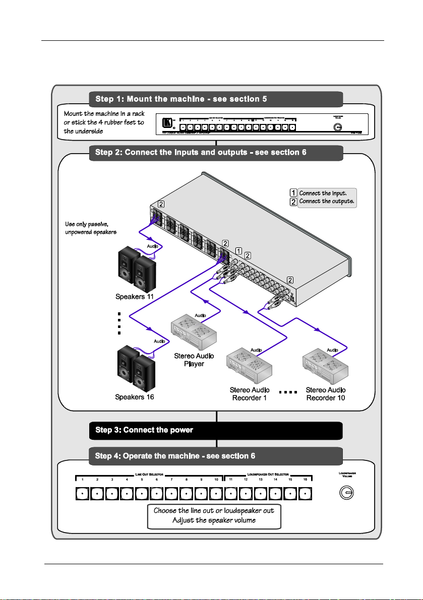
2.1 Quick Start
This quick start chart summarizes the basic setup and operation steps.
2
KRAMER: SIMPLE CREATIVE TECHNOLOGY
Page 5

Overview
3 Overview
The VS-106 is a switcher/amplifier for unbalanced analog audio stereo
signals. The unit mechanically switches the single line input to one output,
either one of ten unpowered unbalanced audio stereo line outputs, or one of
six amplified speaker outputs. The unit does not switch to line and speaker
outputs simultaneously.
More specifically, the VS-106 features:
• Unpowered 1x10 mechanical line to line switching
• Amplified 1x6 line to speaker switching
• A loudspeaker volume knob
• A power ON indication LED
• A 12V DC power supply
• Standard 19” 1 U rack mount size
To achieve the best performance:
• Use only good quality connection cables
1
to avoid interference,
deterioration in signal quality due to poor matching, and elevated
noise levels (often associated with low quality cables).
• Avoid interference from neighboring electrical appliances that
may adversely influence signal quality and position your Kramer
VS-106 away from moisture, excessive sunlight and dust
4 Your VS-106 16 Output Audio Selector/Amplifier
Figure 1 and Table 1 define the unit.
1 Available from Kramer Electronics on our Web site at http://www.kramerelectronics.com
3
Page 6

Your VS-106 16 Output Audio Selector/Amplifier
Figure 1: VS-106 16 Output Audio Selector/Amplifier
4
KRAMER: SIMPLE CREATIVE TECHNOLOGY
Page 7

Installing the VS-106 in a Rack
!
Table 1: VS-106 16 Output Audio Selector/Amplifier Functions
# Feature Function
1 ON LED Illuminates green when receiving power
2 LINE OUT SELECTOR Buttons Press to choose the output line (1 to 10)
3 LOUDSPEAKER OUT SELECTOR Buttons Press to choose the output speaker pair (11 to 16)
4 LOUDSPEAKER VOLUME Knob Turn to adjust the volume level of the selected speakers
5 OUT (SPKR) (L+, L-, R+, R-) Terminal Blocks Connect to the stereo speaker pairs (11 to 16)
6 LINE INPUT (L, R) RCA Connectors Connect to the unbalanced audio stereo line source
7 LINE OUTPUT (L, R) RCA Connectors Connect to the unbalanced audio stereo acceptors (1 to 10)
8 12V DC Connector +12V DC for powering the unit
5 Installing the VS-106 in a Rack
This section describes how to install the VS-106 in a rack.
Before Installing in a rack
Before installing in a rack, be sure that the environment is
within the recommended range:
Operating temperature range +5° to +45° C (41° to 113° F)
Operating humidity range 10 to 90% RHL, non-condensing
Storage temperature range -20° to +70° C (-4° to 158° F)
Storage humidity range 5 to 95% RHL, non-condensing
To rack-mount a machine:
1. Attach both ear brackets to the
How to Rack Mount
machine. To do so, remove the
screws from each side of the
machine (3 on each side), and
replace those screws through the
ear brackets.
When installing on a 19" rack, avoid hazards by taking
CAUTION!!
care that:
1. It is located within the recommended environmental
conditions, as the operating ambient temperature of a
closed or multi unit rack assembly may exceed the
room ambient temperature.
2. Once rack mounted, enough air will still flow around
the machine.
3. The machine is placed straight in the correct
horizontal position.
4. You do not overload the circuit(s). When connecting
the machine to the supply circuit, overloading the
circuits might have a detrimental effect on overcurrent
protection and supply wiring. Refer to the appropriate
nameplate ratings for information. For example, for
fuse replacement, see the value printed on the
product label.
5. The machine is earthed (grounded) in a reliable way
and is connected only to an electricity socket with
grounding. Pay particular attention to situations where
electricity is supplied indirectly (when the power cord
is not plugged directly into the socket in the wall), for
example, when using an extension cable or a power
strip, and that you use only the power cord that is
supplied with the machine.
2. Place the ears of the machine
against the rack rails, and insert the
proper screws (not provided)
through each of the four holes in the
rack ears.
Note that:
• In some models, the front panel
may feature built-in rack ears
• Detachable rack ears can be
removed for desktop use
• Always mount the machine in the
rack before you attach any cables
or connect the machine to the
power
• If you are using a Kramer rack
adapter kit (for a machine that is not
19"), see the Rack Adapters user
manual for installation instructions
(you can download it at:
http://www.kramerelectronics.com)
5
Page 8

Connecting and Operating the VS-106
6 Connecting and Operating the VS-106
To connect the VS-106, as shown in Figure 2, do the following1:
1. Connect an unbalanced stereo audio source (for example, a stereo audio
player) to the LINE INPUT L and R RCA connectors.
2. Connect the LINE OUTPUT RCA connect ors to up to 10 unbalanced stereo
audio acceptors (for example, stereo audio recorders).
3. Connect the OUT (SPKR) connect ors to up to 6 speaker pairs (use only
passive, unpowered speakers).
4. Connect the 12V DC power supply.
To operate the VS-106:
1. Press the appropriate button on the LINE OUT SELECTOR (from 1 to 10)
or the LOUDSPEAKER OUT SELECTOR (from 11 to 16).
The line input switches to the selected line output or speaker.
2. Adjust the speaker volume by turning the LOUDSPEAKER VOLUME
knob.
Note: The power supply is only needed when operating loudspeakers.
No power is needed for line switching.
1 Switch OFF the power on each device before connecting it to your VS-106. After connecting your VS-106, connect its
power and then switch on the power on each device
6 6
KRAMER: SIMPLE CREATIVE TECHNOLOGY
Page 9

Connecting and Operating the VS-106
Figure 2: Connecting the VS-106 16 Output Audio Selector/Amplifier
7
Page 10

Connecting and Operating the VS-106
6.1 Optional Gain Adjustment
You can set the overall gain of the loudspeakers by adjusting the gain
DIP-switches located on the circuit board inside the VS-106. Settings
available are 19dB, 25dB (factory setting), 31dB and 37dB.
To set the gain DIP-switches:
1. Remove the screws from the top and sides that hol d the top c over.
2. Remove the top cover to access the circuit board.
3. Using a small screwdriver or pointed object, slide the DIP-switches to set
the desired gain (see Figure 3
).
4. Replace the top cover and secure with the screws removed as per Step 1
above.
Figure 3: Adjusting the Gain DIP-Switches
8 8
KRAMER: SIMPLE CREATIVE TECHNOLOGY
Page 11

Technical Specifications
7 Technical Specifications
The VS-106 technical specifications are shown in Table 2:
Table 2: VS-106 Technical Specifications1
INPUTS: 1 unbalanced stereo audio on RCA connectors
OUTPUTS: 6 powered speakers on 4-pin terminal blocks;
INPUT SENSITIVITY: 230mVpp @37dB gain program max. level
OUTPUT POWER: 8W RMS per channel into 4Ω
MAX. VOLTAGE GAIN: +37dB (70.8x)
BANDWIDTH (-3dB): >20kHz
S/N RATIO: Power amplifier: 76dB; line level 92dB@1kHz
CONTROLS: Volume control knob
COUPLING: Speakers: input – AC, output – DC
AUDIO THD + NOISE: Power amplifier: 3.5%; line level 0 (no active parts to distort)
AUDIO 2nd HARMONIC: 1.2% @1kHz, power outputs
AMPLIFIER TYPE: Class D
POWER SOURCE: 12V DC, 2A
DIMENSIONS: 19” x 4.0” x 1U
WEIGHT: 1kg (2.2lbs)
ACCESSORIES: Power supply, rack “ears”
10 line level unbalanced audio stereo on RCA connectors
Line: input – DC, output – DC
1 Specifications are subject to change without notice
9
Page 12

LIMITED WARRANTY
Kramer Electronics (hereafter ) warrants this product free from defects in material and workmanship under the
following terms.
HOW LONG IS THE WARRANTY
Labor and parts are warranted for seven years from the date of the first customer purchase.
WHO IS PROTECTED?
Only the first purchase customer may enforce this warranty.
WHAT IS COVERED AND WHA T IS NOT COVERE D
Except as below, this warranty covers all defects in material or workmanship in this product. The following are not covered
by the warranty:
1. Any product which is not distributed by Kramer, or which is not purchased from an authorized Kramer dealer. If you are
uncertain as to whether a dealer is authorized, please contact Kramer at one of the agents listed in the Web site
www.kramerelectronics.com.
2. Any product, on which the serial number has been defaced, modified or removed, or on which the WARRANTY VOID
TAMPERED sticker has been torn,
IF reattached, removed or otherwise interfered with.
3. Dam age, det erioratio n or malfun ction r esulting from:
i) Accident, misus e, abuse, n eglect, fi re, water , lightnin g or othe r acts of na ture
ii) Product mo difica tion, or fai lure to foll ow instr ucti ons s upplie d wit h the pro duc t
iii) Repair or a ttempted repair by a nyone n ot author ized by Kr amer
iv) Any shipment of the produc t (clai ms must b e presente d to the carrier)
v) Removal or i nstalla tion of th e produc t
vi) Any other cause, w hich do es not rel ate to a pro duct d efect
vii) Cartons, equipment enclosures, cables or accessories used in conjunction with the product
WHAT WE WILL PA Y FOR AND WHA T WE WILL NOT PA Y FOR
W e will pa y labor an d mater ial expen ses for c overed i tems. W e will not pay for th e follo wing:
1. Removal or inst allatio ns char ges.
2. Costs of initial technical adjustments (set-up), including adjustment of user controls or programming. These costs are the
responsi bility of the Kra mer deal er from whom the produc t was pur chased.
3. Shipping charges.
HOW YOU CAN GET WARRANTY SERVICE
1. To obtain service on you product, you must take or ship it prepaid to any authorized Kramer service center.
2. Whenever warranty service is required, the original dated invoice (or a copy) must be presented as proof of warranty
coverage, and should be included in any shipment of the product. Please also include in any mailing a contact name,
company, address, and a description of the problem(s).
3. For the name of the nearest Kramer authorized service center, consult your authorized dealer.
LIMITATION OF IMPLIED WARRANTIES
All implied warranties, including warranties of merchantability and fitness for a particular purpose, are limited in duration to
the length of this warra nty.
EXCLUSION OF DAMAGES
The liability of Kramer for any effective products is limited to the repair or replacem ent of the product at our option. Kramer shall
not be liabl e for:
1. Damage to o ther pr operty cau sed by defe cts in th is prod uct, damage s based upon inco nvenien ce, loss of use of the pr oduct, l oss
of time, commercial loss; or:
2. Any othe r da mage s, w het her i nciden tal, co nseque nti al or oth erwi se. Some c oun tries may not all ow lim ita tions o n how l ong an
implied warrant y lasts and/or do not allo w the exclusion or limitation of i ncidental or consequential damage s, so the above
limita tion s and ex clus ions ma y no t apply to yo u.
This warra nty giv es you spec ific l egal rights , and yo u may also have oth er right s, which var y from p lace to pl ace.
NOTE:
All pr oducts r eturne d to Krame r for se rvice m ust have pr ior ap proval. This ma y be obta ined from your dea ler .
This equipment has been tested to determine compliance with t he requirements of:
EN-50081: "Electromagnetic compatibility (EMC);
Reside ntia l, com mercia l and l ight indus try"
EN-50082: "Electromagnetic compatibility (EMC) gen eric immunity standard.
CFR-47: FCC* Rules and Regulations:
CAUTION!
generic emission standard.
Part 1:
Part 1 : Resi denti al, co mmer cial an d lig ht in dustry envir onme nt".
Part 15: “Radio freq uency devic es
Subpart B Unintentional radiators”
Servicing the machines can only be done by an authorized Kramer technician. Any user who makes changes or
modifications to the unit without the expressed approval of the manufacturer will void user authority to operate the
equipment.
Use the supplied DC power supply to feed powe r to the machine.
Please use recommended interconnection cables to connect t he machine to other components.
* FCC and CE approved u sing STP cable ( for twiste d pair prod ucts)
Kramer
10 10
KRAMER: SIMPLE CREATIVE TECHNOLOGY
Page 13

For the latest information on our products and a list of Kramer
distributors, visit our Web site:
www.kramerelectronics.com
where updates to this user manual may be found.
We welcome your questions, comments and feedback.
Safety Warning:
Disconnect the unit from the power supply before
opening/servicing.
Caution
Kramer Electronics, Ltd.
Web site: www.kramerelectronics.com
E-mail: info@kramerel.com
P/N: 2900-000647 REV 1
 Loading...