

Page 1

Kramer Electronics, Ltd.
USER MANUAL
Model:
VP-747T
Presentation Switcher Co n t rol Panel
Page 2

Contents
i
Contents
1 Introduction 1
1.1 About the VP-747T Presentation Switcher Control Panel 1
2 Getting Started 2
2.1 Quick Start 2
3 Overview 3
4 Your VP-747T Presentation Switcher Control Panel 4
5 Installing in a Desktop 8
6 Installing on a Rack 10
7 Connecting the VP-747T 11
7.1 Setting the Machine # 12
7.2 Connecting to the VP-747 by Wired Connecti on 13
8 Operating the VP-747 using the VP-747T 14
8.1 Using the VP-747T WIPE DIRECTION Buttons 14
8.2 Making the Transition 15
8.2.1 Making a Transition Manually 15
8.2.2 Making a Transition Automatically 15
9 Technical Specifications 15
Figures
Figure 1: VP-747T Presentati o n S witcher Control Pa ne l 5
Figure 2: VP-747T Presentati o n S witcher Control Pa ne l (Side Panel)
Figure 3: Cut Out Dimensions 8
Figure 4: Inserting the VP-747T into the Prepared Cut Out Opening
Figure 5: Inserting the Mounting Brackets through the Bracket Slits
Figure 6: Securing the VP-747T into the Prepared Cut Out Opening
Figure 7: Connecting the VP-747T 12
Figure 8: Connecting the VP-747T RS-485 Ports
7
8
9
9
13
Tables
Table 1: VP-747T Presentation Switcher Control Panel Features 6
Table 2: VP-747T Presentation Switcher Control Pa ne l (Side Panel) Features
Table 3: Defining the WIPE DIRECTIONS Buttons
Table 4: Technical Specifications of the VP-747T 15
7
14
Page 3

Introduction
1 1
1 Introduction
Welcome to Kramer Electronics! Since 1981, Kramer Electronics has been
providing a world of unique, creat iv e, and aff orda ble s oluti ons to t he vast range
of problems that confront the video, a u di o, presen t ation, and broadcasting
professional on a daily basis. In recent years, we have redesigned and upgraded
most of our line, making the bes t ev en be tter! Our 1,000-plus different models
now appear in 11 groups
Congratulations on purchasing your Kramer VP-747T Presentation Switcher
Control Panel, which is ideal for staging events, as well as:
• Presentation applications that require a preview option
• Projection sy st ems in conf erence r oom s , boa rd rooms, auditoriums, hotels,
and churches
1.1 About the VP-747T Presentation Switcher Control Panel
1
that are clearly defined by function.
The Kramer VP-747T Presentation Switcher Control Panel is use d to c ont rol
the VP-747 Universal Presentati on Matrix Switcher / Scaler
2
. The Kramer
VP-747T lets you remotely control switcher functions such as input selection,
transition effects (that include cut, fade, and wipes) and transition speed.
Note that the VP-747 needs firmware package Master FW 1.03 (Ver . 1.03 or
higher) to work with the VP-747T.
The package includes: the VP-747T, gooseneck lamp, null-modem adapter,
power supply, rack ears kit
user manual
4
.
3
, table-top brackets, 2 mini-XLR connectors and this
1 GROUP 1: Distribution Amplifiers; GROUP 2: Switchers and Matrix Switchers; GROUP 3: Control Systems;
GROUP 4: Format/Standards Converters; GROUP 5: Range Extenders and Repeaters; GROUP 6: Specialty AV Products;
GROUP 7: Scan Converters and Scalers; GROUP 8: Cables and Connectors; GROUP 9: Room Connectivity;
GROUP 10: Accessories and Rack Adapters; GROUP 11: Sierra Products
2 A true multi-standard video to graphics scaler and seamless switcher with 2 DVI/HDMI inputs as well as 8 universal inputs
comprised of 5 BNC connectors each of w hich can accommodate a composite video, s-Video (Y/C), component video
(RGB/YUV), RGBS, or RGBHV signal. It has dual scalers, one for the preview and the other for the pro gram output. Dual
scalers are required to do "live" seamless transitions from one source to another
3 A pair of rack ears, two spacers and ten screws
4 Download up-to-date Kramer user manuals from the Internet at this URL: http://www.kramerelectronics.com
Page 4
KRAMER: SIMPLE CREATIVE TECHNOLOGY
Getting Started
2
2 Getting Started
We recommend that you:
• Unpack the equipment carefully and save the original box and packaging
materials for possible future shipment
• Review the contents of this user manual
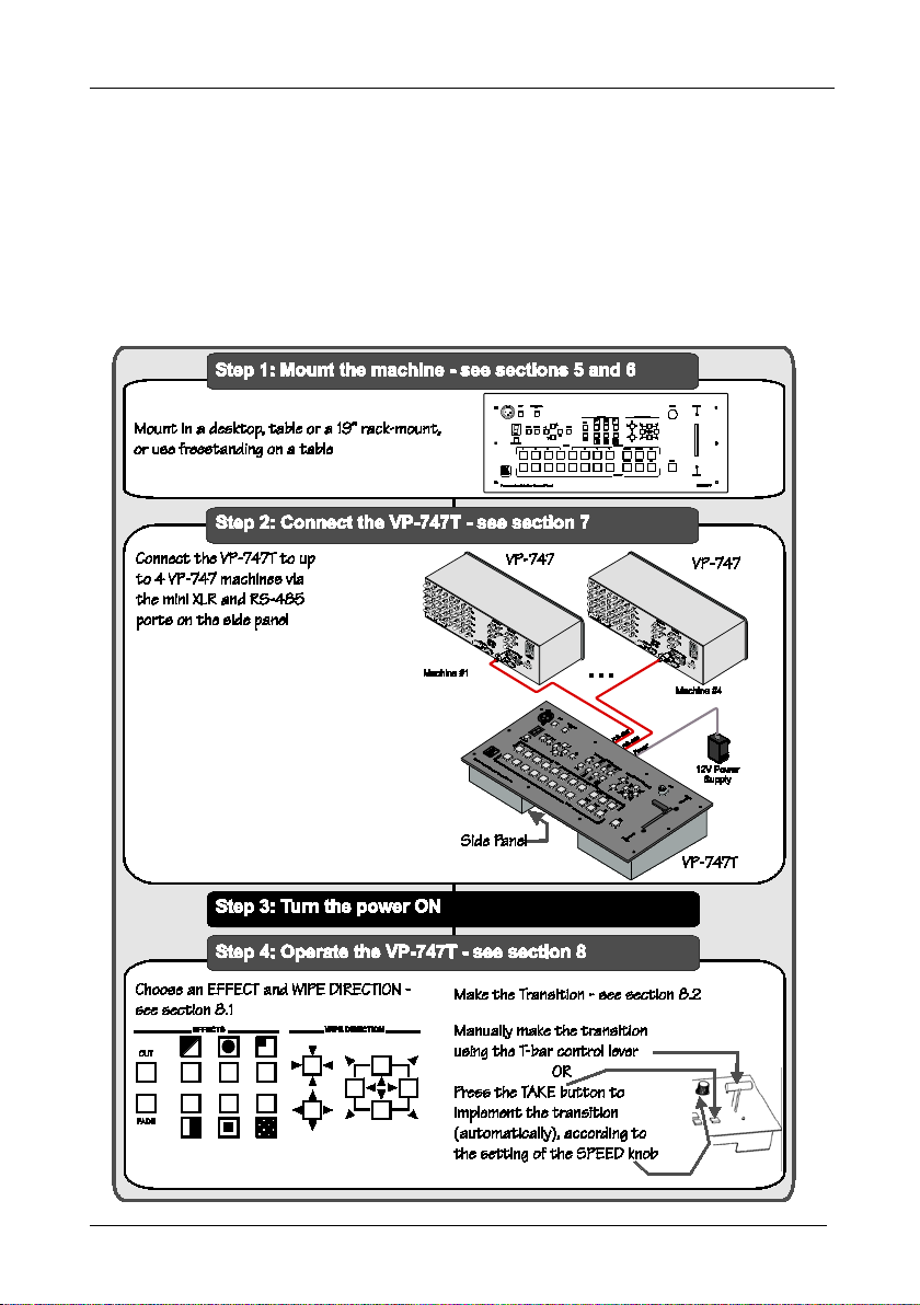
2.1 Quick Start
This Quick start chart summarizes the basic steps when connecting a VP-747T:
Page 5

3 3
3 Overview
Overview
The VP-747T is a unique presentation switcher control panel dedicated
specifically to control the VP-747
1
. It is ergonomically and aesthetically
designed in a rugged, profess i onal 19" 4U ra ck-mountable metal enclosure with
the button layout in the style of the VP-747. In particular, the VP-747T:
• Enables special effect transitions between two sources via a robust T-bar
(used for manual control of transition speeds). Alternatively, the effect can
be implemented via a TAKE button, with a potentiometer to set the
transition speed
2
• Features single button access to all inputs
—both for the Preview an d for
the Program output—and the buttons have removable transparent caps to
allow labeling
• Features dedicated single button actions for special effect selection,
immediate freezing and blanking , PIP dis pl ay, and th e ch oi ce of wi pe
direction
• Has the user menu—conveniently located on the VP-747T panel—for
complete control of the VP-747
via its Preview OSD
• Consol can be simultaneously connected to up to four VP-747 machines,
using two mini XLR connectors and tw o t erm inal bl ock connector s . The
communication is via RS-485, thus allowing the panel to be locate d more
than 1km from each VP-747
• Has an RS-232 port for field upgrading of its firmw a re
• With its angled faceplate, may be used freestanding on a table, or mounted
in a desktop or in a 19” rack (when your switcher is rack-mounted near to
the source devices, you can conveniently place the VP-747T
on a table or
desk away from the equipment rack)
• Has a gooseneck l amp (in c luded) t h at can be plu gg e d into th e con s ol for
use in low lighting environments
• Is powered by a 12V DC source
1 The VP-747 is also backward compatible to the VP-727T
2 Has two sets of i nput buttons: one that routes the input to the "PROGRAM" output and the other that routes to the
"PREVIEW" output
Page 6
KRAMER: SIMPLE CREATIVE TECHNOLOGY
Your VP-747T Presentation Switcher Control Panel
4
To achieve the best performance:
• Connect only good qu a lity conne ction cables
• Avoid interference from neighboring electrical appliances, make sure not to
block the ventilation holes and position your VP-747T
away from
moisture, excessive sunlight and du s t. Be sure t o posi t ion it s traight in the
correct horizontal position on the table, desk or rack
4 Your VP-747T Presentation Switcher Control Panel
Figure 1 and Table 1 define the front panel of the VP-747T:
Page 7

Your VP-747T Presentation Switcher Control Panel
5
Figure 1: VP-747T Presentation Switcher Control Panel
Page 8

KRAMER: SIMPLE CREATIVE TECHNOLOGY
Your VP-747T Presentation Switcher Control Panel
6
Toggles the VP-747T Presentation Switcher Control Panel ON/OFF
1
2
5
6
Table 1: VP-747T Presentation Switcher Control Panel Feat ur e s
# Feature Function
1 LAMP Button Toggles the gooseneck lamp ON/OFF
2 MENU Button Displays the OSD Menu screen (or moves to the pre vious level in the OSD menu)
3 ENTER Button Moves to the next level in the OSD menu
4 CONTROLLER ON
Button
5
6
OSD
7
8
9 OSD Button Activates/deactivates ac cess to the OSD Menu
10 FADE 2 Button Selects a dissolved transition from the PREVIEW to the PROGRAM output
11 CUT
3 5,
12
13
14
15
16
17
TRANSITION Buttons
18 WIPE DIRECTION
Buttons
19 ) SPEED Knob Adjusts the TAKE button transition s pe e d
20 TAKE Button
21 PREVIEW LED Lights when the T-bar Controller is directed upwards
22 PREVIEW LED Lights when the T-bar Controller is directed downwards
23 T-bar Control Lever
24
25 BLANK Toggles between a b lank screen and th e sel ec ted in put
26 FREEZE Freezes the output video image (toggl e)
PROGRAM
27 INPUTS Se lects one o f the sou rces: R/ PR, G/Y/CV, B/PB/C, HS/CS, VS (from 1 to 8)
28
29 BLANK Toggles between a b lank screen and th e sel ec ted in put
30 FREEZE Freezes the output video image (toggl e)
PREVIEW
31 INPUTS Se lects one o f the sou rces: R/ PR, G/Y/CV, B/PB/C, HS/CS, VS (from 1 to 8)
32 MACHINE # Button Pressing selects which MACHINE # is controlled
33 7-segment LED Display Shows the MACHINE #
34 Lamp Connector C on ne cts to t he goosen ec k la mp
Buttons
NAVIGATION
PIP Toggles the picture-in-picture function on an d o ff
Buttons
PIP Toggles the picture-in-picture function on an d o ff
Buttons
Toggles within each level 2 command / decreases the range by one step
Moves up one step (in the same level) in the OSD menu
Toggles within each leve l 2 c o mmand / increa ses the r ange by one step
Moves down one step (in the same level) in the OSD menu
Selects an instantaneous transition from the PREVIEW to the PROGRAM output Button
Selects a WIPE transition effect
Selects a DIAGONAL transition effec t
Selects a CIRCLE transition e ff ect
Selects a SQUARE transition effect
Selects a CORNER transition ef fec t
Selects a CHESSBOARD transition effect
Choose the direction of the e ff ec t4: inwards, outward s, “lef t t o r ight” , “ right to
left”, “up” or “down” (see
Pressing TAKE causes the transiti on to occur automatically
Slide to manually implement the effect u sing t he T-bar handle
Section 8.1
1 The LCD is not affected by the OSD setting
2 Only for setting up the unit for the effect. The effect will only occur when the Take button is pressed, or the T-bar is moved
3 Select a specific effect for the transition from the PREVIEW output to the PROGRAM output
4 From where the effect starts
5 The effect is only seen in PROGRAM Mode. The PREVIEW screen will blank during the transition
6 An alternative to using the TAKE button
Page 9

Your VP-747T Presentation Switcher Control Panel
Side Panel
Figure 2 and Table 2 define the side panel of the VP-747T:
Figure 2: VP-747T Presentation Switcher Control Panel (Side Panel)
Table 2: VP-747T Presentation Switcher Control Panel (Side Panel) Features
# Feature Function
1
2 MACH. # 2 RS-485 Mini
3 MACH. # 3 (A B G)
4 MACH. # 4 (A B G)
5 RS-232 9-pin D-sub Connector Connects to the PC for upgrading the fi rmware
6 12V DC +12V DC connector for powering the unit
MACH. # 1 RS-485 Mini
XLR Connector
XLR Connector
1
RS-485
3-pin Terminal
Block Connector
TO VP-747
1
RS-485
Block Connector
Connects to the Mini XLR Connector on the VP-747 which is recognized as
machine # 1
Connects to the Mini XLR Connector on the VP-747 which is recognized as
machine # 2
Connects to the Mini XLR Connector port on the VP-747 which is
recognized as machine # 3
Connects to the Mini XLR Connector on the VP-747 which is recognized as
machine # 4 3-p in Terminal
2
1 Pin G is for the Ground connection, which is sometimes connected to the shield of the RS-485 cable. In most applications,
the ground is not connected; pins B (-) and A (+) are for RS-485
2 Download the latest version of firmware and installation instructions at http://www.kramerelectronics.com
7
Page 10

KRAMER: SIMPLE CREATIVE TECHNOLOGY
Installing in a Desktop
8
5 Installing in a Desktop
1
This section describes how to install the VP-747T in a desktop
To install the VP-747T in a deskt op:
1. Cut an opening in the desktop—making t he cut out on a wooden surface
using a sabre saw or a keyhole saw—at t he location where you want to
insert the VP-747T.
Figure 3 illustra te s the cut out template (not to scale)
defining the surface that you have to cut out to install your VP-747T.
Figure 3: Cut Out Dimensions
2. Carefu lly ins ert th e VP-747T unit into the prepared cut out opening, as
illustrated in
Figure 4.
.
Figure 4: Inserting the VP-747T into the Prepared Cut Out Opening
1 Alternatively, you can use it freestanding on a table, or mounted in a 19” rack (see Section 6)
Page 11

Installing in a Desktop
3. Insert the two mounting brackets through the bracket slits on both sides of
the VP-747T unit (se e
Figure 5).
Figure 5: Inserting the Mounting Brackets through the Bracket Slits
4. Be sure that the upper outer rim is situated parallel to the edge of the desktop.
5. Screw the mounting butterfly screws u ntil they re ach the desktop surface
(from the underneath).
6. Tighten the locking butterfly screws to lock the mounting butterfly screws.
The VP-747T unit is now secured in plac e , a s illustrated in
Figure 6.
Figure 6: Securing the VP-747T into the Prepared Cut Out Opening
9
Page 12

KRAMER: SIMPLE CREATIVE TECHNOLOGY
Installing on a Rack
10
6 Installing on a Rack
This section provides instructions for ra ck mounting the unit .
Page 13

Connecting the V P-747T
7 Connecting the VP-747T
To connect the VP-747T to up to four VP-747 m achines, as the example in
Figure 7 illustrates, do the following15F1:
1. Connect the “TO VP-747” mini XLR connector of the VP-747T (by
one-to-one connection) to the VP-747, as follows:
MACH. # 1 to the mini XLR connector of th e VP-747 which will be
recognized as machine # 1
MACH. # 2 to the mini XLR connector of the VP-747 which will be
recognized as machine # 2
2. Connect the “TO VP-747” 3-pin terminal block ports of the VP-747T (by
wired connection) to the VP-747, as follows (see section
MACH. # 3 to the mini XLR connector of the VP-747 which will be
recognized as machine # 3
MACH. # 4 to the mini XLR connector of the VP-747 which will be
recognized as machine # 4
3. Set the “T-Bar Optimization” mode in the “Transition” menu of the
VP-747 to On.
4. Connect the 12V DC power adapter to the power socket and connect the
adapter to the mains electricity (not illustrated in
If you want to control several units simultaneously, press the MACHINE #
button until the letter A is selected in the 7-segment LED display (A=ALL).
UFigure 7U).
U 7.2U):
One of the units must be connected to port #1 for units to be controlled
simultaneously.
1 Switch OFF the power on each device before connecting it to your VP-747T. After connecting your VP-747T, switch on its
power and then switch on the power on each device
11
Page 14

KRAMER: SIMPLE CREATIVE TECHNOLOGY
Connecting the V P-747T
12
7.1 Setting the Machine #
The VP-747T automatically recognizes the MACHINE # of each VP-747 unit.
For example, the VP-747 unit that is connected to the “TO VP-747” RS 485
port MACH. # 3 is recognized as the third VP-747 unit: MACHINE # 3.
To access this particular VP-747 unit from the VP-747T, press the MACHINE
# button
1
until the number 3 is selected in the 7-segment LED display
1 Item 32 in Figure 1 and Table 1
2 Item 33 in
Figure 1 and Table 1
Figure 7: Connecting the VP-747T
2
.
Page 15

Connecting the V P-747T
VP-747T Side Panel
VP-747 Mini XLR Connector
RS-485 PINOUT
G
B
A
_
+
7.2 Connecting to the VP-747 by Wired Connection
When connecting the “TO VP-747” RS 485 3-pin terminal block ports of the
VP-747T, to the respective VP-747 machine, as illustrated in
Figure 8, connect
the:
• “A” (+) PIN of the VP-747T to the “A” (+) PIN of the VP-747
• “B” (+) PIN of the VP-747T t o the “B” (+) PIN of the VP-747
• If shielded twisted pair cable is used, the shield may be connected to the
“G” (Ground) PIN on one of the units
Figure 8: Connecting the VP-747T RS-485 Ports
13
Page 16

KRAMER: SIMPLE CREATIVE TECHNOLOGY
Operating the VP-747 using the VP-747T
14
Down
Up
Left to right
Right to left
In
Out
In
Out
Each block performs as shown
in the “Square” above
8 Operating the VP-747 using the VP-747T
To operate the VP-747 via the VP-747T, set the VP-747 “Optimize T-bar”
mode in the “Transition” menu to On.
For details of how to operate the VP-747 via the OSD Menu, LCD Display,
ETHERNET, and/or RS-232, including using the TAKE button, refer to the
VP-747 user manual
• Use the WIPE DIRECTION buttons, see section
• Adjust the transition speed, see section
8.1 Using the VP-747T WIPE DIRECTION Buttons
To set the wipe direction, use the WIPE DIRECTION
EFFECTS WIPE DIRECTIONS
Wipe
Diagonal
1
. For details of how to:
8.1
8.2
buttons2 (see Table 3):
Table 3: Defining the WIPE DIRECTIONS Buttons
Choice of four
directions (only
one button is
selected)
Choice of four
directions (two
buttons are
selected
simultaneously)
Circle
Square
Corner
Chessboard
In
In
In
1 Download up-to-date Kramer user manuals from the Internet at: http://www.kramerelectronics.com
2 Item 18 in Figure 1 and Table 1
Out
Out
Choice of four
directions (two
buttons are
selected
simultaneously)
Out
Page 17

8.2 Making the Transition
7
Technical Specifications
You can make the transition in two ways:
• Manually, for each separate transition using the T-bar control lever
• Automatically, via the TAKE button, which implements the transition at the
pace set by the SPEED
8.2.1 Making a Transition Manually
2
knob
To make the transition, ma nually:
3
• Slide the T-bar handle upwards
or downwards
8.2.2 Making a Transition Automatically
4
To make the transition, automatically:
2
• Rotate the SPEED knob
to the right (increasing the transition speed) or to
the left (decreasing the transition s pee d). When th e knob is turned to the
extreme counter-clockwise position (off), the switch will be engaged to turn
the knob off. In this posit ion, th e spee d s etting is cont rol led vi a th e se tti ng
in the VP-747 OSD menu
5
• Pressing the TAKE button
causes the transition to occur automatically
9 Technical Specifications
includes the technical specifications:
Table 4
Table 4: Technical Specifications
PORTS:
CONTROLS: Front panel buttons, mini XLR and RS-485
POWER SOURCE: 12V DC, 280mA
DIMENSIONS: 19” (W), 3.4” (D), 4RU (H) rack mountable
WEIGHT:
ACCESSORIES: Gooseneck lamp, 2 mini XLR connectors, power supply, rack ears
2 sets of mini XLR ports
2 sets of RS-485 3-pin terminal block ports
1.58kg (3.5lbs) approx.
8
kit
, and table-top brackets
6
of the VP-747T
1
1 Item 23 in
2 Item 19 in
3 The PREVIEW LED lights (item 21 in
4 The PREVIEW LED lights (item 22 in
5 Item 20 in
6 Specifications are subject to change without notice
7 48.2cm (W), 8.6cm (D), 17.7cm (H)
8 A pair of rack ears, two spacers and ten screws
Figure 1 and Table 1
Figure 1 and Table 1
Figure 1 and Table 1)
Figure 1 and Table 1)
Figure 1 and Table 1
15
Page 18

KRAMER: SIMPLE CREATIVE TECHNOLOGY
16
LIMITED WARRANTY
WHO IS PROTECTED?
WHAT IS COVERED AND WHA T IS NO T COVERED
WHAT WE WILL P A Y F OR AND WHA T WE WILL N OT P A Y FOR
HOW YOU CAN GET WARRANTY SERVICE
LIMITA TION OF IMPLIED W ARRANTIES
EXCLUSION OF DAMAGES
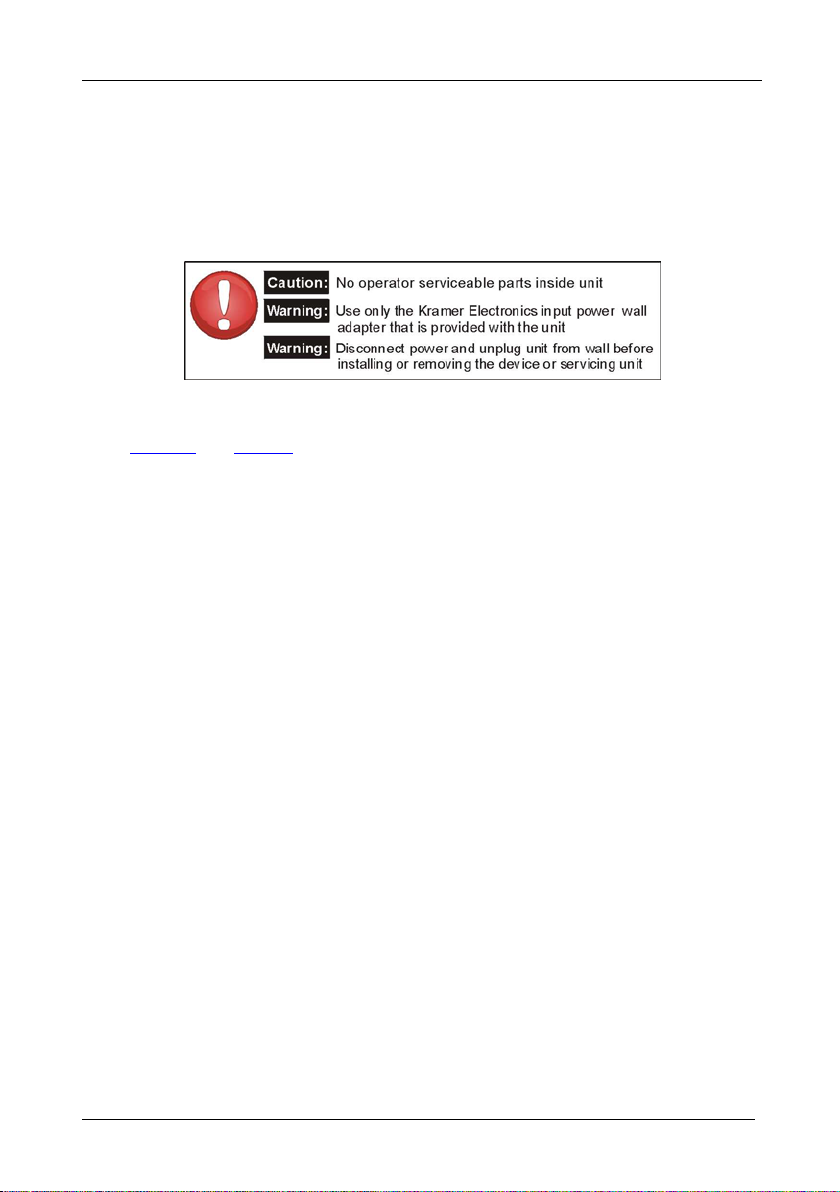
CAUTION!
Kramer Electronics (hereafter ) warrants this product free from defects in material and workmanship under the
following terms.
Kramer
HOW LONG IS THE WARRANTY
Labor and parts are warranted for seven years from the date of the first customer purchase.
Only the first purchase customer may enforce this warranty.
W e will pa y labor a nd mat erial ex pense s for c overe d items. W e will n ot pay for the follo wing:
The liab ilit y of K ramer for an y ef fec tive p rod ucts is lim ite d to th e rep air or repl ace ment of the produ ct a t our optio n. Krame r shal l
not be li able for:
This war ranty gives y ou speci fic l egal rig hts, a nd you ma y also have oth er rig hts, w hich var y from p lace to place.
All produc ts retur ned t o Kramer f or ser vice m ust hav e prior a pprov al. Th is may b e obta ined from your deale r.
This equ ipmen t has be en teste d to de termi ne compl iance w ith t he requir emen ts of:
EN-5008 1: "Electrom agnetic compat ibili ty (EMC );
generic emission standard.
Residenti al, com mercia l and lig ht ind ustry "
EN-5008 2: "Electrom agnetic compat ibili ty (EMC ) gener ic immu nity st anda rd.
Part 1: R esiden tial, comme rcial an d light indus try env ironme nt".
CFR-47: FCC* Rules and Regulations:
Part 15: “Ra d io frequency devices
Subpart B Unintentional radiators”
Except as below, this warranty covers all defects in material or workmanship in this product. The following are not covered
by the warranty:
1. Any product which is not distributed by Kramer, or which is not purchased from an authorized Kramer dealer. If you are
uncertain as to whether a dealer is authorized, please contact Kramer at one of the agents listed in the Web site
www.kramerelectronics.com.
2. Any product, on which the serial number has been defaced, modified or removed, or on which the WARRANTY VOID
T AMP ER E D sti c ke r has be e n to r n,
3. Damage, det eriora tion o r malf unction resu lting f rom:
i) Accident, misuse, abuse, neglect, fire, water, l ightn ing or o ther ac ts of nat ure
ii) Product m odifi cation , or fai lure to f ollow instru ction s suppli ed wit h the pr oduc t
iii) Repair o r atte mpted r epair by a nyone not au thoriz ed by Kra mer
iv) Any ship ment of th e pro duct (c laims m ust be pr esente d to th e carri er)
v) Removal or inst alla tion of the pro duct
vi) Any other cause, which does not relate to a product defect
vii)Cartons, e quipme nt encl osure s, cabl es or accesso ries use d in c onjunct ion wi th the p roduct
1. Rem oval or insta llatio ns char ges.
2. Costs of initial technical adjustments (set-up), including adjustment of user controls or programming. These costs are the
respon sibili ty of th e Krame r deal er from wh om the produ ct was pu rchas ed.
3. Shippin g char ges.
1. To obtain service on you product, you must take or ship it prepaid to any authorized Kramer service center.
2. Whenever warranty service is required, the original dated invoice (or a copy) must be presented as proof of warranty
coverage, and should be included in any shipment of the product. Please also include in any mailing a contact name,
company, address, and a description of the problem(s).
3. For the name of the nearest Kramer authorized service center, consult your authorized dealer.
All implied warranties, including warranties of merchantability and fitness for a particular purpose, are limited in duration to
the length of this warranty.
1. Damage to other p roper ty cause d by defe cts in this prod uct, damages based upo n inco nvenie nce, lo ss of use of the pro duct, loss
of time, commercial lo ss; or:
2. Any ot her d ama ges , whe ther inc ide ntal, co nseq uen tia l or oth erwi se. Som e co untr ies may not all ow li mit ati ons o n how l ong an
implied warranty lasts and/or do not allow the exclusion or limitation of incidental or consequential damages, so the above
limita tions a nd excl usions m ay no t apply to you.
Servicing the machines can only be done by an authorized Kramer technician. Any user who makes changes or
modifications to the unit without the expressed approval of the manufacturer will void user authority to operate the
equipment.
Use the supplie d DC powe r sup ply to f eed pow er to the mach ine.
Please use recommended interconnection cables to connect the machine to other components.
IF reattached, removed or otherwise interfered with.
* FCC and CE appro ved using S TP ca ble (f or twist ed pair pr oducts )
NOTE:
Part 1:
Page 19

For the latest information on our products and a list of Kramer
distributors, visit our Web site: www.kramerelectronics.com,
where updates to this user manual may be found.
We welcome your questions, comments an d feedb a ck.
Safety Warning:
Disconnect the unit from the power supply before
opening/servicing.
Caution
Kramer Electronics, Ltd.
Web site: www.kramerelectronics.com
E-mail: info@kramerel.com
P/N: 2900-000636 REV 1
 Loading...