

Page 1
VW-4 Quick Start
P/N:
2900- 301453QS
Rev:
2
Scan for full manual
VW-4 Quick Start Guide
This guide helps you install and use your VW-4 for the first time.
Go to www.kramerav.com/downloads/VW-4 to download the latest user manual and check if firmware
upgrades are available.
Step 1: Check what’s in the box
VW-4 4 Output Video-Wall Driver
1 Bracket set
1 Quick start guide
1 Power adapter and cord
4 Rubber feet
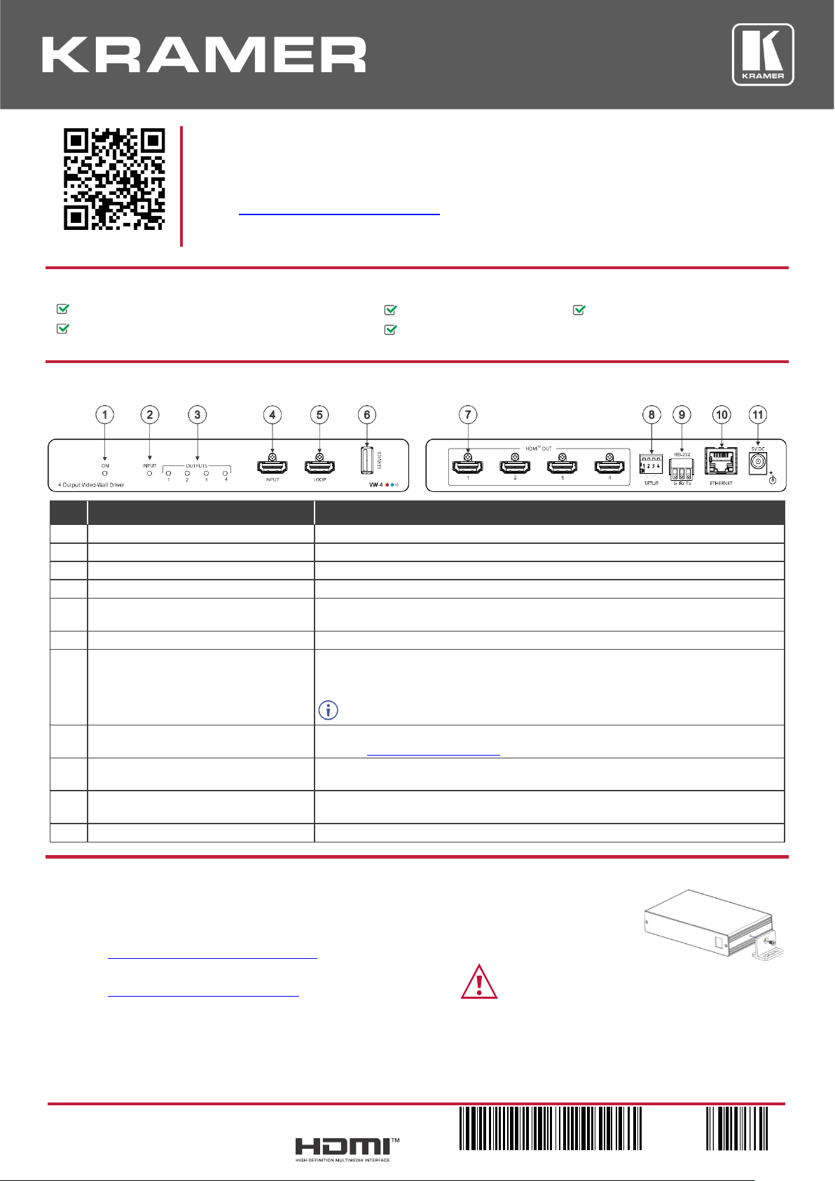
Step 2: Get to know your VW-4
#
Feature
Function
1
ON LED
Lights green when the device is powered.
2
INPUT LED
Lights green when a valid input signal is detected on the input.
3
OUTPUT LEDs (1 to 4)
Light green when an acceptor is detected on that output.
4
INPUT HDMI Connector
Connect to an HDMI source.
5
LOOP HDMI Connector
Connect to an additional VW-4 device for configuring a large video wall or to a
local monitor.
6
SERVICE USB Port
Use to perform firmware upgrade.
7
OUT HDMI Connectors (1 to 4)
Connect to up to 4 HDMI acceptors that make up the video wall configuration.
The appropriate segments of the zoomed picture are output on these connectors
for connection to the displays in the video-wall.
The output on these connectors is at 1080P resolution.
8
SETUP 4-way DIP-switch
For fast, basic configuration of the device without needing to be connected to a
PC, see Step 6: Configure VW-4.
9
RS-232 3-pin terminal block connector
Use to setup and monitor the VW-4 via the Windows software and to upgrade the
firmware.
10
ETHERNET RJ-45 Connector
Connect to a PC via a LAN to setup and monitor the VW-4 via the configuration
app.
11
5V DC Connector
Connect to the supplied power adapter.
Step 3: Mount VW-4
Install VW-4 using one of the following methods:
• Attach the rubber feet and place the unit on a flat surface.
• Fasten a bracket (included) on each side of the unit and attach it to a flat surface
(see www.kramerav.com/downloads/VW-4).
• Mount the unit in a rack using the recommended rack adapter
(see www.kramerav.com/product/VW-4).
• Ensure that the environment (e.g., maximum ambient temperature &
air flow) is compatible for the device.
• Avoid uneven mechanical loading.
• Appropriate consideration of equipment nameplate ratings should be
used for avoiding overloading of the circuits.
• Reliable earthing of rack-mounted equipment should be maintained.
• Maximum mounting height for the device is 2 meters.
Page 2
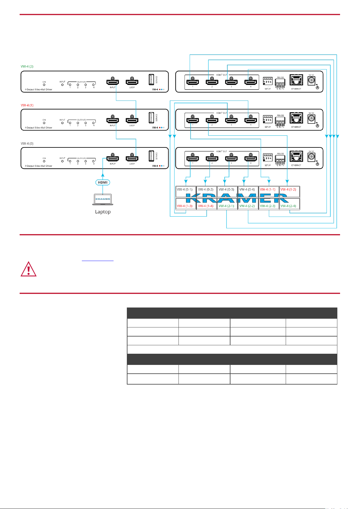
Step 4: Connect inputs and outputs
The three devices in this 6x2 diagram are designated 0, 1 and 2. Each output is designated by the device number and its
outputs. For example, VW-4 (1) is the second device in this video wall configuration and VW-4 (1-2) is HDMI OUT 2 on that
device.
Step 5: Connect power
Connect the power adapter to VW-4 and plug it into the mains electricity.
Safety Instructions (See www.kramerav.com for updated safety information)
Caution:
• For products with relay terminals and GPI\O ports, please refer to the permitted rating for an external connection, located next to the terminal or in the User Manual.
• There are no operator serviceable parts inside the unit.
Warning:
• Use only the power cord that is supplied with the unit.
• Disconnect the power and unplug the unit from the wall before installing.
Step 6: Configure VW-4
Configure VW-4 via:
• DIP-switch settings – for basic
video wall configuration.
• VW-4 app, via the Ethernet or
RS-232.
• Remotely, by RS-232 serial
commands transmitted by a
touch screen system, PC, or
other serial controller.
RS-232 Control / Protocol 3000
Baud Rate:
115,200
Parity:
None
Data Bits:
8
Command Format:
ASCII
Stop Bits:
1
Example: (Set Auto-sync Off to Fast): #SCLR-AS 1,2
Default Ethernet Parameters
IP Address:
192.168.1.39
Gateway:
192.168.0.1
Subnet mask:
255.255.0.0
TCP Port #:
5000
Page 3
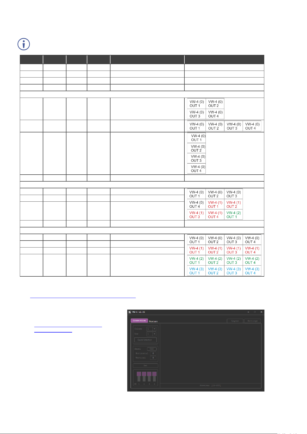
Video Wall Configuration via DIP-switch Settings
You can use the DIP-switch settings to quickly configure a basic video wall (without bezel correction) of up to 4x4, consisting
of 1 or more VW-4 devices.
When the video wall size is configured using the DIP-switches, it is not possible to set it up via the configuration
app. (To use the app, make sure that the DIP-switches are all OFF).
DIP 1
DIP 2
DIP 3
DIP 4
Columns x Rows Layout
Notes
OFF
OFF
OFF
OFF
Basic setup is not used (default)
OFF
OFF
OFF
ON
Full size picture (“1x1” wall)
Image appears on all displays.
OFF
OFF
ON
OFF
N/A OFF
OFF
ON
ON
N/A One VW-4 Device
OFF
ON
OFF
OFF
2x2 wall (0)
OFF
ON
OFF
ON
4x1 wall (0)
OFF
ON
ON
OFF
1x4 wall (0)
OFF
ON
ON
ON
N/A Three VW-4 Devices
ON
OFF
OFF
OFF
3x3 wall, first unit (0)
ON
OFF
OFF
ON
3x3 wall, second unit (1)
ON
OFF
ON
OFF
3x3 wall, third unit (2)
ON
OFF
ON
ON
N/A Four VW-4 Devices
ON
ON
OFF
OFF
4x4 wall, first unit (0)
ON
ON
OFF
ON
4x4 wall, second unit (1)
ON
ON
ON
OFF
4x4 wall, third unit (2)
ON
ON
ON
ON
4x4 wall, fourth unit (3)
Video Wall Configuration via the configuration app
Use the VW-4 Windows® Control Software app to configure a video wall of up to 8x8, consisting of 1 or more VW-4 devices
(see www.kramerav.com/product/VW-4#Tab_Resources).
To configure the video wall (for example, a 3x2 video wall, using 2 devices):
1. Download the latest VW-4 Control
Software app from
www.kramerav.com/product/VW4#Tab_Resources.
2. Open the app.
3. Click Connection.
The Connection window opens, showing a
list of all the connected VW-4 devices and
the available RS-232 ports on your PC.
The Connection window opens.
Page 4
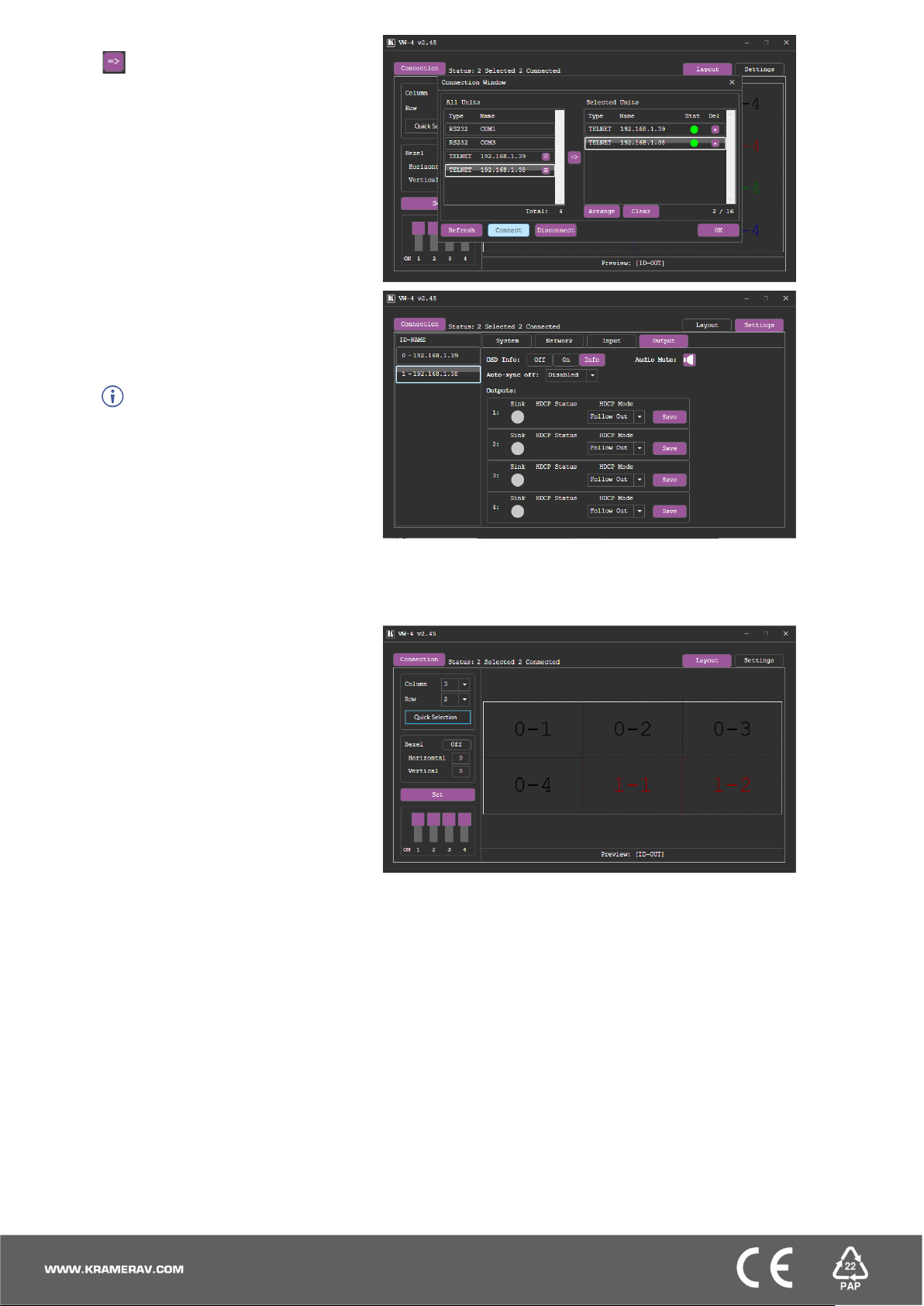
4. Select a device under All Units and click
.
The selected device moves to the
Selected Units area.
5. Add the other connected devices.
6. Click OK.
7. Select the Settings tab and then select the
Output tab.
8. If you need to change the device ID, enter
the new ID under ID-NAME and press
Enter on your keyboard.
You can set the ID number
individually only when the device is directly
connected to your PC.
The ID number is set to each device, and
according to that number each device is
assigned its physical position in the video
wall setup.
9. View the sink status of each device output
and:
▪ Set OSD Info.
▪ Define Auto-Sync Off status.
▪ Set the HDCP per output and
click Save.
10. Select the Layout tab.
11. Set the video wall size by either:
▪ Selecting Column and Row
numbers (for example, 3 x 2).
OR
▪ Clicking Quick Selection for
common video wall
configurations.
12. Select horizontal and vertical bezel
corrections (in pixels).
For each connected device, VW-4 App also enables performing factory reset, upgrading the firmware, viewing network
settings and copying the EDID to the input from a selected EDID source.
 Loading...