

Page 1
P/N: 2900-300582 Rev 6 www.kramerAV.com
USER MANUAL
MODELS:
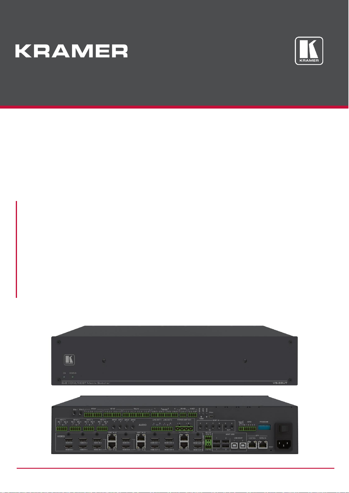
VS-88UT
8x8 HDMI/HDBT Matrix Switcher
VS-84UT
8x4 HDMI/HDBT Matrix Switcher
Page 2

Kramer Electronics Ltd.
VS-88UT – Contents
i
Contents
Introduction 1
Getting Started 1
Overview 2
Typical Applications 4
Controlling your VS-88UT 4
Defining the VS-88UT and VS-84UT 5
Mounting VS-88UT 9
Connecting VS-88UT and VS-84UT 10
Connect the VS-88UT Matrix Ports 10
Connect the VS-84UT Matrix Ports 12
Connect the Controller Ports 14
Connecting the Audio Inputs and Outputs 15
Connecting to VS-88UT via RS-232 16
Connecting VS-88UT via the Ethernet Port 16
Using the Web Pages 19
Globally Muting video and audio signals 22
Defining Global Settings 23
Routing VS-88UT Ports 29
Defining Port Settings 30
Managing EDID 60
Controlling Devices via the Controller 64
Room Controller Configuration via K-Config 3 65
Controlling Devices 67
Activating Macros 72
Scheduling Macros 73
Setting the Date and Time 75
Configuring Device Automation 76
Changing the Device Settings 78
Resetting to Factory Default Parameters 78
Setting Authentication 79
Changing the Ethernet Settings 82
Performing Firmware Upgrade 83
Setting the Date and Time 84
Viewing the About Page 85
Technical Specifications 86
Default Communication Parameters 88
Protocol 3000 89
Understanding Protocol 3000 89
Protocol 3000 Commands 90
Result and Error Codes 106
Page 3

Kramer Electronics Ltd.
VS-88UT – Introduction
1
Introduction
Welcome to Kramer Electronics! Since 1981, Kramer Electronics has been providing a world
of unique, creative, and affordable solutions to the vast range of problems that confront the
video, audio, presentation, and broadcasting professional on a daily basis. In recent years, we
have redesigned and upgraded most of our line, making the best even better!
Getting Started
We recommend that you:
• Unpack the equipment carefully and save the original box and packaging materials for
possible future shipment.
• Review the contents of this user manual.
Go to www.kramerav.com/downloads/VS-88UT or www.kramerav.com/downloads/VS-84UT to
check for up-to-date user manuals, application programs, and to check if firmware upgrades are
available (where appropriate).
Achieving the Best Performance
• Use only good quality connection cables (we recommend Kramer high-performance,
high-resolution cables) to avoid interference, deterioration in signal quality due to poor
matching, and elevated noise levels (often associated with low quality cables).
• Do not secure the cables in tight bundles or roll the slack into tight coils.
• Avoid interference from neighboring electrical appliances that may adversely influence
signal quality.
• Position your Kramer VS-88UT away from moisture, excessive sunlight and dust.
Safety Instructions
Caution:
• This equipment is to be used only inside a building. It may only be connected to other
equipment that is installed inside a building.
• For products with relay terminals and GPI\O ports, please refer to the permitted rating
for an external connection, located next to the terminal or in the User Manual.
• There are no operator serviceable parts inside the unit.
Warning:
• Use only the power cord that is supplied with the unit.
• Disconnect the power and unplug the unit from the wall before installing.
• Do not open the unit. High voltages can cause electrical shock! Servicing by qualified
personnel only.
• To ensure continuous risk protection, replace fuses only according to the rating
specified on the product label which located on the bottom of the unit.
Page 4

Kramer Electronics Ltd.
VS-88UT – Introduction
2
Recycling Kramer Products
The Waste Electrical and Electronic Equipment (WEEE) Directive 2002/96/EC aims to reduce
the amount of WEEE sent for disposal to landfill or incineration by requiring it to be collected
and recycled. To comply with the WEEE Directive, Kramer Electronics has made
arrangements with the European Advanced Recycling Network (EARN) and will cover any
costs of treatment, recycling and recovery of waste Kramer Electronics branded equipment on
arrival at the EARN facility. For details of Kramer’s recycling arrangements in your particular
country go to our recycling pages at www.kramerav.com/support/recycling.
Overview
Congratulations on purchasing your Kramer VS-88UT 8x8 HDMI/HDBT Matrix Switcher
and/or VS-84UT 8x4 HDMI/HDBT Matrix Switcher.
The devices described in this user manual are generally referred to as VS-88UT. A device is
named specifically only when a device-specific feature is described.
VS-88UT is a high-performance 4K@60Hz (4:2:0) Audio-Video presentation system with
integrated range extension and an integrated control system master. The unit switches the
video, embeds the audio and outputs the signal to both HDMI™ and HDBaseT 2.0 with USB
extension and PoE. Outstanding audio support includes balanced stereo audio, unbalanced
stereo audio and de-embedded audio sources that output to embedded audio, balanced
stereo audio as well as a power amplified audio output.
VS-88UT includes a master room controller that can operate over Ethernet (LAN) with control
ports that include: one bidirectional RS-485, four RS-232, four IR, four GPI/O, and eight relays
to control a wide variety of AV devices. It includes a KNET™ connector interface that enables
access to the master controller from auxiliary room controllers such as control keypads. The
unit can also provide power to auxiliary room controllers via the KNET™ connectors. The
VS-88UT includes an Ethernet gateway to control and manage remote I/O ports.
The VS-88UT provides exceptional quality, advanced and user-friendly operation, and flexible
control.
Exceptional Quality
• Max. Data Rate – 10.2Gbps (3.4Gbps per graphic channel).
• Max. Resolution – 4K@60Hz (4:2:0).
• Audio Level control.
• HDMI, HDCP and DVI compliance.
• HDBaseT certified – V2.0 support.
• HDBaseT Extension Reach – Up to 100m at 4K @60Hz (4:2:0), up to 130m (430ft) at full
HD (1080p @60Hz 36bpp), up to 180m (590ft) at ultra-mode and full HD
(1080p @60Hz 24bpp).
• USB Support – USB 1.1 and USB 2.0 (up to 127Mbps) channelled through HDBaseT.
Page 5

Kramer Electronics Ltd.
VS-88UT – Introduction
3
• HDMI Support – Deep color, 3D, 7.1 PCM as specified in HDMI 2.0.
• Kramer reKlocking™ and equalization technology – Rebuilds the digital signal to travel
longer distances.
Advanced and User-friendly Operation
• Advanced EDID management per input.
• Active source and acceptor detection.
• Control options – RS-232 serial commands transmitted by a PC, touch screen system or
other serial controller, Ethernet port via LAN.
• Simple and Powerful Maestro 1.5 Room Automation – Intuitive user interface enables
you to fully automate your meeting room elements. Configure lights, shades, devices
and more to be activated by an extensive range of triggers, including scheduling,
input/output connectivity, routing, and button pressing. By minimizing user intervention,
Maestro room automation saves meeting prep time and minimizes human error before
presentations.
• Kramer K-Config™ Compatible – Windows®-based control program for easy
configuration and upload to room controller over customer IP network.
• Kramer Network Compatible – Remote control and management over customer IP
network.
• Programmable Step-In over HDMI and HDBT – When used in conjunction with
compatible step-in devices, such as the SID-X3N and DIP-31 (using an HDMI cable that
supports HEC, the HDMI Ethernet Channel).
• Simultaneous IP control communication – With up to 15 IP control clients.
• Auto-switching and auto-scanning of inputs.
• Audio breakaway and AFV (audio-follow-video) operation support.
• Global mute for both video and audio outputs – Allowing easy integration of the audio
system with a public announcement audio system in case of an emergency event.
• Firmware Upgrade – Ethernet-based, via a user-friendly software upgrade tool.
• Kramer protocol 3000 support.
• Advanced EDID management per input.
• Includes non-volatile memory that retains the last settings after switching the power off
and then on again.
Flexible Connectivity
• For VS-88UT:
▪ 4 HDMI and 4 HDMI/HDBT (selectable) inputs.
▪ 4 balanced stereo audio inputs or 8 microphone inputs (selectable) as well as 4
unbalanced stereo inputs.
▪ 6 HDMI and 2 HDBT outputs.
▪ 6 IR ports for HDBT tunneling.
Page 6

Kramer Electronics Ltd.
VS-88UT – Introduction
4
• For VS-84UT:
▪ 6 HDMI and 2 HDBT inputs.
▪ 4 balanced stereo audio inputs or 8 microphone inputs (selectable) as well as 4
unbalanced stereo inputs.
▪ 2 HDMI and 2 HDBT outputs.
▪ 4 IR ports for HDBT tunneling.
• 2 line-out balanced stereo audio outputs and one audio amplified output.
• 2 USB type-A hubs and 2 USB Type-B ports.
• 1 Ethernet port – Connects to control gateways for I/O port extending, and controls
IP-enabled controlled devices.
• 1G Ethernet port – For tunneling data via HDBT ports.
• 1 K-NET™ connector – Carrying both power and control communication; connects to
room control system, either master room controller, or auxiliary control keypads.
• 1 RS-485 and 2 RS-232 bidirectional control ports – Control devices via bidirectional
serial control protocols.
• 4 IR emitter control ports – Control devices via IR control protocols.
• 4 GPI/O control ports – Control devices via general purpose I/O ports, individually
configurable as digital input, digital output or analog input interface for controlling
sensors, door-locks, audio volume and light dim level, or lighting control devices.
• 8 Relay control ports – Control devices via relay contact closure, such as scrolling up
and down screens, drapes, shades, and blinds.
• IR Sensor and IR input ports – Learn commands from IR remotes.
Typical Applications
The VS-88UT is ideal for the following typical applications:
• Projection systems in conference rooms, boardrooms, hotels and churches.
• Divisible conference rooms in hotels.
• Classroom, lecture theatres and education applications.
Controlling your VS-88UT
Control your VS-88UT via:
• By RS-232 serial commands transmitted by a touch screen system, PC, or other serial
controller (see Connecting to VS-88UT via RS-232 on page 16).
• Ethernet using built-in user-friendly Web pages (see Using the Web Pages on page 19).
Page 7
Kramer Electronics Ltd.
VS-88UT – Defining the VS-88UT and VS-84UT
5
Defining the VS-88UT and VS-84UT
This section defines the VS-88UT and VS-84UT.
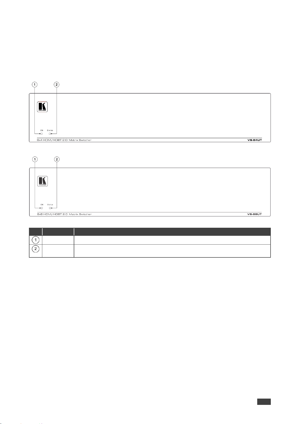
Figure 1: VS-84UT 8x4 HDMI/HDBT Matrix Switcher Front Panel
Figure 2: VS-88UT 8x8 HDMI/HDBT Matrix Switcher Front Panel
#
Feature
Function
ON LED
Lights when receiving power.
STATUS
LED
Multi-color LED lights upon startup, flashes green upon boot and lights green when
ready to use. The LED lights red to indicate internal errors.
Page 8

Kramer Electronics Ltd.
VS-88UT – Defining the VS-88UT and VS-84UT
6
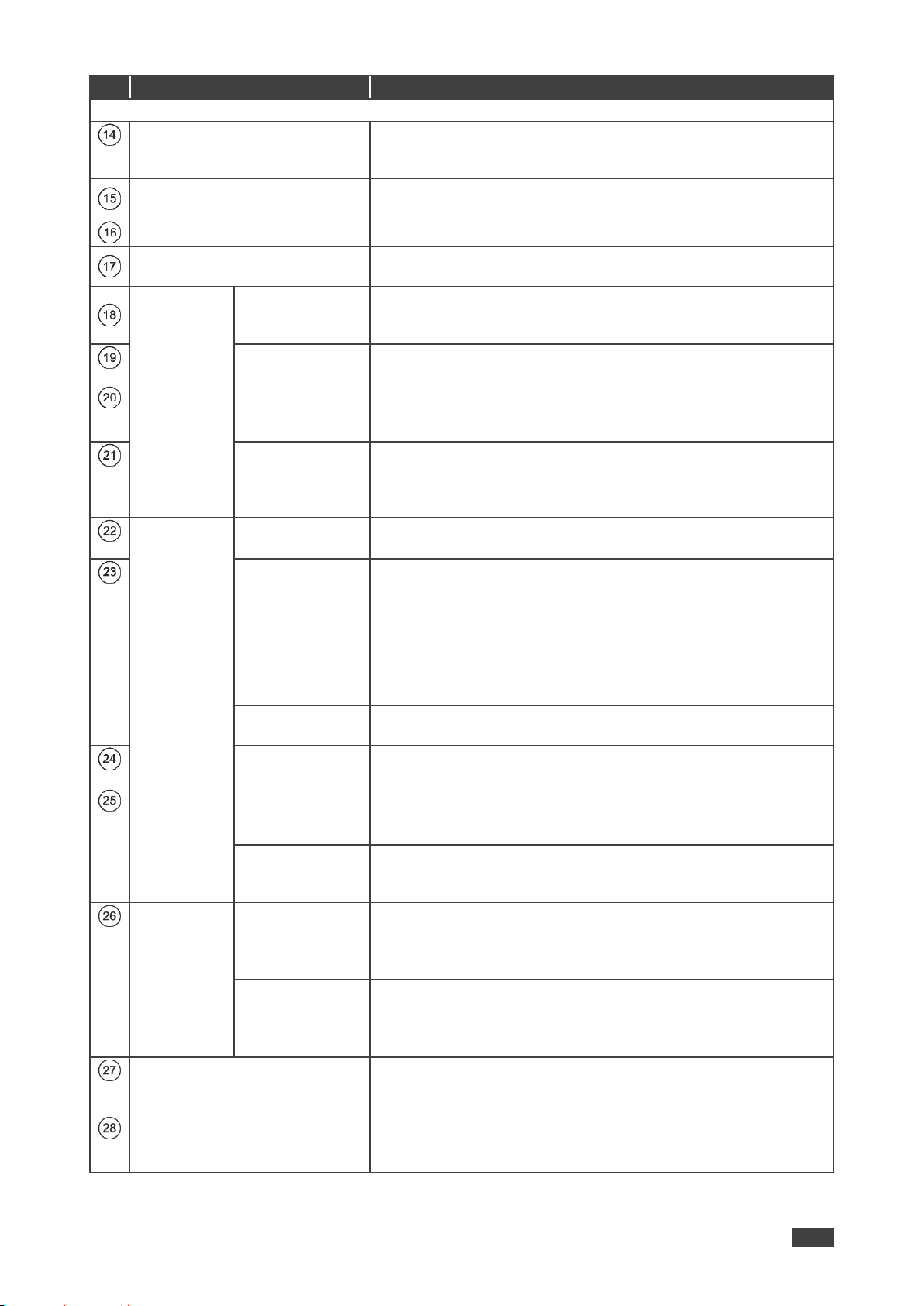
Figure 3: VS-88UT 8x8 HDMI/HDBT Matrix Switcher Rear Panel
Figure 4: VS-84UT 8x4 HDMI/HDBT Matrix Switcher Rear Panel
#
Feature
Function
Room Controller Functionality
IR IN 1 3.5mm Mini Jack
Connect to an external IR receiver (1 and 2).
IR OUT Terminal Block
Connectors
Connect to IR emitter cables (from 1 to 4).
GPI/O Terminal Block
Connectors
Connect to various analog and digital sensors (from 1 to 4).
RELAYS Terminal Block
Connectors
Connect to low-voltage relay-driven devices (from 1 to 8).
RS-232 Terminal Block
Connectors
Connect to RS-232 controlled devices (from 1 to 4).
RS-485 Terminal Block
Connector
Connect to the RS-485 port on a switcher or PC.
Pins B (-) and A (+) are for RS-485; Pin G may be connected to
the shield (if required).
K-NET Terminal Block
Connector
Use with the K-Config control system. PIN GND is for the
Ground connection; PIN B (-) and PIN A (+) are for RS-485, and
PIN +12V is for powering other devices.
RS-485 TERM Switch
Slide down for RS-485 termination with 120; slide up for no
RS-485 line termination.
The first and the last units on the RS-485 line should be
terminated (ON). Other units should not be terminated (OFF).
K-NET TERM Switch
Use with the K-Config control system.
Slide down (in the direction of the arrow) for K-NET termination;
slide up for bus to not be terminated. The last physical device on
a K-NET bus must be terminated.
PROG Switch
For factory use only.
PROG Mini USB Connector
For factory use only.
Page 9
Kramer Electronics Ltd.
VS-88UT – Defining the VS-88UT and VS-84UT
7
#
Feature
Function
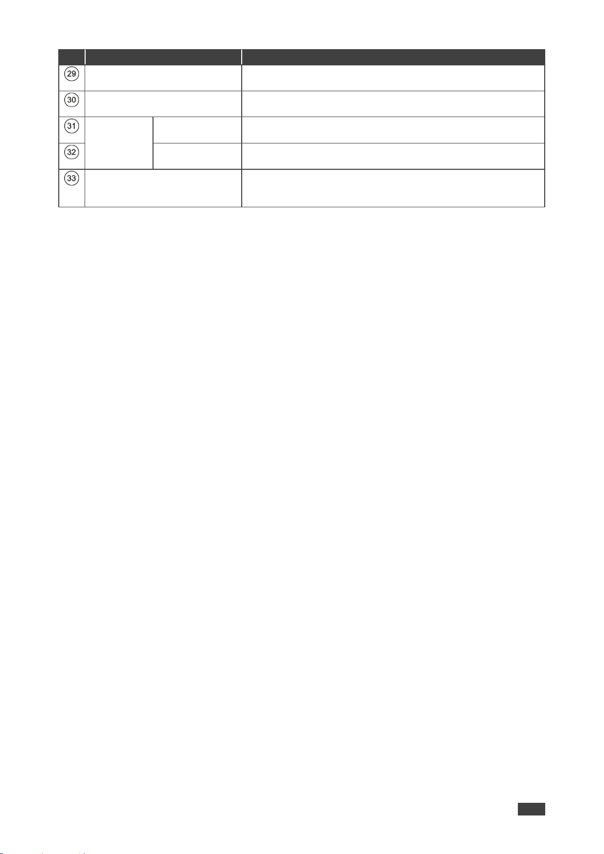
Matrix Functionality
REMOTE MUTE 2-pin Terminal
Block Connector
Remote switch to mute all video and audio signals. Enables easy
integration of the audio system with a PA system, usually used
for alarms or other public audio messages.
GPIO 5-pin Terminal Block
Connectors
For future use.
PROGRAM DIP-switches
For future use.
Power Connector with Switch
and Fuse
AC connector, enabling power supply to the unit.
Power switch for turning the unit on or off.
AUDIO
INPUT (MIC/line)
5-pin Terminal
Block Connectors
Connect to stereo audio balanced sources (from 1 to 4) and/or
microphone inputs (from 1 to 8).
INPUT 3.5mm
Mini Jack
Connect to an unbalanced audio source (from 5 to 8).
LINE OUT 5-pin
Terminal Block
Connectors
Connect to a stereo balanced audio acceptor (1 and 2).
POWER AMP
OUT 4-pin
Terminal Block
Connectors
Connect to a pair of loudspeakers.
VIDEO
HDMI IN
Connector
VS-88UT: connect to an HDMI source (from 1 to 4).
VS-84UT: connect to an HDMI source (from 1 to 6).
HDMI IN—HDBT
IN Connectors
VS-88UT: connect a source to the HDMI IN 5 and/or HDMI IN 6
inputs, or connect a transmitter to the HDBT IN (5) and/or HDBT
IN (6) inputs. The same applies to the HDMI IN 7/8 and HDBT IN
(7)/(8) pairs. For each input pair (HDMI or HDBT), only one type of
connector can be enabled (via the Routing Settings Web page);
by default, the HDBT pair is active. The HDBT Transmitter (for
example, the Kramer TP-590Txr) can pass audio and video
signals as well as USB, Ethernet, power and serial commands.
HDBT IN
Connectors
VS-84UT: connect to an HDBT transmitter (from (7) to (8)).
HDMI OUT
Connectors
VS-88UT: connect to an HDMI acceptor (1, 2, 3, 4, 7 and 8).
VS-84UT: connect to an HDMI acceptor (1 to 2).
OUT (HDBT)
Connectors
VS-88UT: connect OUT 5 and/or OUT 6 to HDBT receivers (for
example, the Kramer TP-590Rxr) to pass audio and video signals
as well as USB, Ethernet, power and serial commands.
HDBT OUT
Connectors
VS-84UT: connect to HDBT receivers (for example, the Kramer
TP-590Rxr) to pass audio and video signals as well as USB,
Ethernet, power and serial commands.
HDBT IR
3.5mm Mini
Jack
IN
VS-88UT: connect to an external IR sensor to send IR signals (5,
6, 7 and 8) via HDBT inputs 5, 6, 7 and 8 respectively.
VS-84UT: connect to an external IR sensor to send IR signals (7
and 8) via HDBT inputs 7 and 8 respectively.
OUT
VS-88UT: connect to an external IR emitter to receive IR signals
(5 and 6) via HDBT outputs 5 and 6, respectively.
VS-84UT: connect to an external IR emitter to receive IR signals
(3 and 4) via HDBT outputs 3 and 4, respectively.
RS-232 HDBT DATA Terminal
Block Connectors (G, Rx, Tx)
Connect to the PC or the remote controller and pass data
between this RS-232 port and the HDBT OUT ports or one of the
HDBT IN ports.
RS-232 CONTROL Port
Terminal Block Connectors (G,
Rx, Tx)
Connect to the PC or the remote controller to control the
VS-88UT via Protocol 3000 commands.
Page 10
Kramer Electronics Ltd.
VS-88UT – Defining the VS-88UT and VS-84UT
8
#
Feature
Function
HDBT USB Device Port Pairs
Connect up to two USB clients to each pair (1 and 2) to pass
data via the HDBT inputs or outputs.
HDBT USB HOST Ports
Connect to a USB host (1 and 2) to pass data via the HDBT
inputs or outputs.
ETH
RJ-45 Ports
CONTROL
Connect to the PC or other controller through computer
networking.
DATA 1G
Connect to the PC or other controller via the Ethernet to pass
data between HDBT ports and the controller.
RESET Recessed Button
Press briefly to restart the system. Press for about 5 seconds to
reset settings to factory default values and then restart the
system.
Page 11
Kramer Electronics Ltd.
VS-88UT – Mounting VS-88UT
9
Mounting VS-88UT
This section provides instructions for mounting VS-88UT. Before installing, verify that the
environment is within the recommended range:
• Operation temperature – 0 to 40C (32 to 104F).
• Storage temperature – -40 to +70C (-40 to +158F).
• Humidity – 10% to 90%, RHL non-condensing.
• VS-88UT must be placed upright in the correct horizontal position.
Caution:
• Mount VS-88UT before connecting any cables or power.
Warning:
• Ensure that the environment (e.g., maximum ambient temperature & air flow) is
compatible for the device.
• Avoid uneven mechanical loading.
• Appropriate consideration of equipment nameplate ratings should be used for avoiding
overloading of the circuits.
• Reliable earthing of rack-mounted equipment should be maintained.
To mount the VS-88UT on a rack
Attach both ear brackets by removing the screws from each side of
the machine and replacing those screws through the ear brackets or
place the machine on a table.
For more information go to www.kramerav.com/downloads/VS-88UT
Page 12

Kramer Electronics Ltd.
VS-88UT – Connecting VS-88UT and VS-84UT
10
Connecting VS-88UT and VS-84UT
This section describes how to:
• Connect the VS-88UT Matrix Ports on page 10.
• Connect the VS-84UT Matrix Ports on page 12.
• Connect the Controller Ports on page 14.
• Connecting the Audio Inputs and Outputs on page 15.
• Connecting to VS-88UT via RS-232 on page 16.
▪ Connecting VS-88UT via the Ethernet Port on page 16.
Always switch off the power to each device before connecting it to your VS-88UT. After
connecting your VS-88UT, connect its power and then switch on the power to each
device.
Note that not all the ports are connected in the following example.
Connect the VS-88UT Matrix Ports
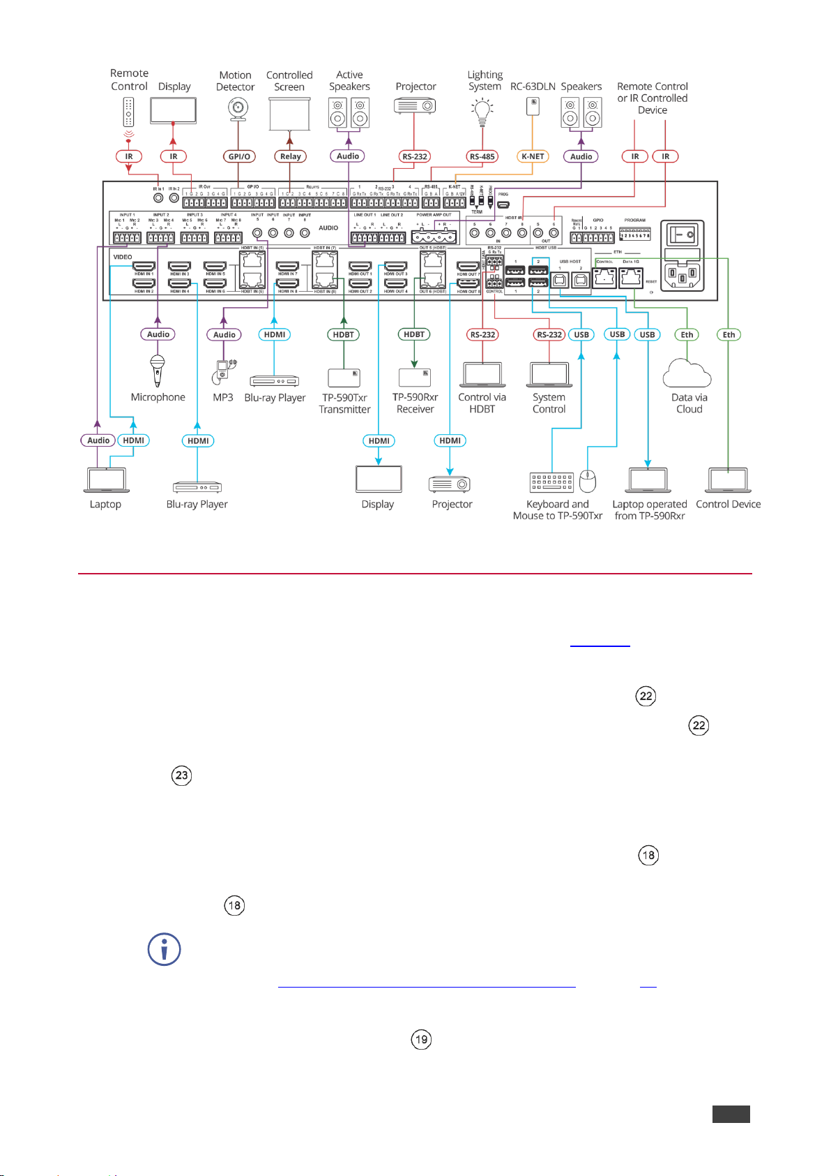
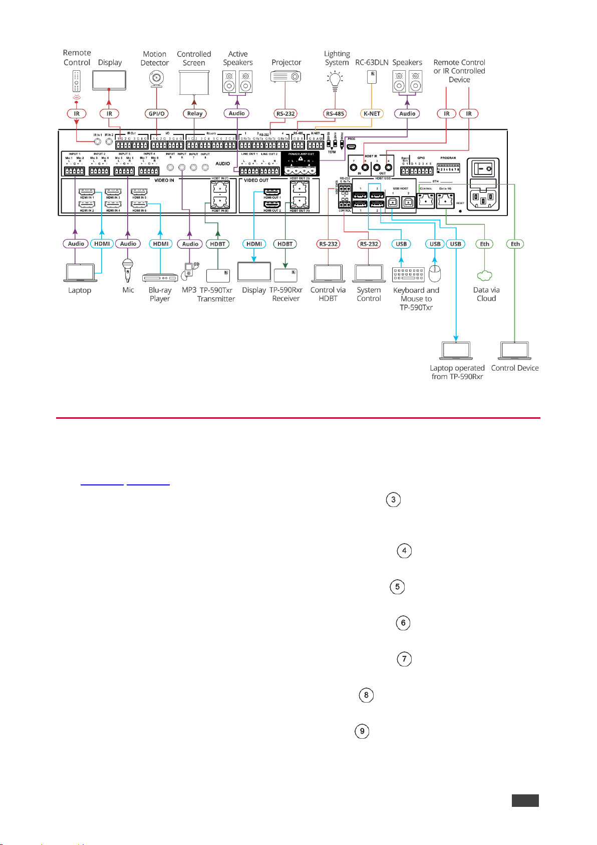
To connect the VS-88UT Matrix as illustrated in the example in Figure 5:
1. Connect the HDMI and HDBT sources:
▪ An HDMI source (for example, a laptop) to the HDMI 1 IN connector .
▪ An HDMI source (for example, a Blu-ray player) to the HDMI 4 IN connector .
▪ An HDMI source (for example, a Blu-ray player) to the HDMI IN 8 HDMI
connector .
▪ A transmitter (for example, the Kramer TP-590Txr) to the HDBT IN (8) RJ-45 port
.
You can enable one of each HDMI and HDBT input pair (5, 6, 7 and 8) via the embedded
web pages (see Setting Input HDBT/HDMI or HDBT Input Port Parameters on page 39).
2. Connect the audio sources:
▪ An audio source (for example, the laptop audio output signal) to the AUDIO INPUT 1
balanced stereo analog audio 5-pin terminal block connector (1 to 4) .
▪ A microphone to the AUDIO MIC 4 balanced audio 3-pin terminal block connector
(1 to 8) .
You can connect each AUDIO analog input 5-pin terminal block connector to either
a balanced stereo audio analog source or to up to two microphones via the web
pages (see Setting Analog Audio Input Port Parameters on page 46).
Page 13
Kramer Electronics Ltd.
VS-88UT – Connecting VS-88UT and VS-84UT
11
▪ An audio source (for example, an MP3 player) to the AUDIO INPUT 5 analog audio
3.5mm mini jack connector (5 to 8) .
3. Connect the HDMI and HDBT outputs:
▪ The HDMI OUT 3 HDMI connector (1 to 4, 7 and 8) , to an HDMI acceptor (for
example, a display).
▪ The OUT 6 (HDBT) RJ-45 port (5 to 6) to a receiver (for example, the Kramer
TP-590Rxr).
4. Connect the audio outputs:
▪ The AUDIO LINE OUT (1 to 2) Terminal Block connector to a balanced audio
acceptor (for example, active speakers).
▪ The POWER AMP OUT block connector to a pair of loudspeakers, by connecting
the left loudspeaker to the “L+” and the “L-” terminal block connectors, and the right
loudspeaker to the “R+” and the “R-” terminal block connectors.
Do not ground the loudspeakers.
5. Connect the IR ports:
▪ HDBT IR IN 8 (5 to 8) 3.5mm mini jack to a room controller (for example, the
Kramer RC-74DL) to control a peripheral device, such as Blu-ray player that
connects to the transmitter that is connected to HDBT IN (8).
▪ HDBT IR OUT 6 (5 to 6) 3.5mm mini jack to an IR controlled device (for example,
a Blu-ray player) so that it can be controlled by a controller that is connected to a
receiver that connects to the OUT 6 (HDBT) port.
6. Connect the USB ports:
▪ A keyboard and a mouse to HDBT USB 2 ports .
The USB signal passes via HDBT IN to a transmitter (for example TP-590Txr) where
a laptop can be controlled.
▪ A laptop to USB HOST 1 port .
A receiver (for example TP-590Rxr) connected to HDBT OUT controls this
connected laptop.
7. Connect RS-232 3-pin terminal blocks:
▪ RS-232 HDBT DATA – Connect to a laptop to control peripheral devices that are
connected to transmitters/receivers that connect to the HDBT IN / HDBT OUT ports.
▪ RS-232 CONTROL – Connect to a laptop to control VS-88UT.
8. Connect ETH ports:
▪ CONTROL – Connect to a laptop to control VS-88UT.
▪ DATA 1G – Connect to the Ethernet to pass data via the cloud.
Page 14
Kramer Electronics Ltd.
VS-88UT – Connecting VS-88UT and VS-84UT
12
Figure 5: Connecting to the VS-88UT Rear Panel
Connect the VS-84UT Matrix Ports
To connect the VS-84UT Matrix as illustrated in the example in Figure 6:
1. Connect the HDMI and HDBT sources:
▪ An HDMI source (for example, a laptop) to the HDMI 1 IN connector .
▪ An HDMI source (for example, a Blu-ray player) to the HDMI 6 IN connector .
▪ A transmitter (for example, the Kramer TP-590Txr) to the HDBT IN (8) RJ-45 port
.
2. Connect the audio sources:
▪ An audio source (for example, the laptop audio output signal) to the AUDIO INPUT 1
balanced stereo analog audio 5-pin terminal block connector (1 to 4) .
▪ A microphone to the AUDIO MIC 6 balanced audio 3-pin terminal block connector
(1 to 8) .
You can connect each AUDIO analog input 5-pin terminal block connector to either
a balanced stereo audio analog source or to up to two microphones via the web
pages (see Setting Analog Audio Input Port Parameters on page 46).
▪ An audio source (for example, an MP3 player) to the AUDIO INPUT 5 analog audio
3.5mm mini jack connector (5 to 8) .
3. Connect the HDMI and HDBT outputs:
Page 15
Kramer Electronics Ltd.
VS-88UT – Connecting VS-88UT and VS-84UT
13
▪ The HDMI OUT 1 HDMI connector (1 to 2) , to an HDMI acceptor (for example, a
display).
▪ The HDBT OUT (4) RJ-45 port (3 to 4) to a receiver (for example, the Kramer
TP-590Rxr).
4. Connect the audio outputs:
▪ The AUDIO LINE OUT (1 to 2) Terminal Block connector to a balanced audio
acceptor (for example, active speakers).
▪ The POWER AMP OUT block connector to a pair of loudspeakers, by connecting
the left loudspeaker to the “L+” and the “L-” terminal block connectors, and the right
loudspeaker to the “R+” and the “R-” terminal block connectors.
Do not ground the loudspeakers.
5. Connect the IR ports:
▪ HDBT IR IN 8 (7 to 8) 3.5mm mini jack to a room controller (for example, the
Kramer RC-74DL) to control a peripheral device, such as Blu-ray player that
connects to the transmitter that is connected to HDBT IN (8).
▪ HDBT IR OUT 4 (3 to 4) 3.5mm mini jack to an IR controlled device (for example,
a Blu-ray player) So that it can be controlled by a controller that is connected to a
receiver that connects to the HDBT OUT (4) port.
6. Connect the USB ports:
▪ A keyboard and a mouse to HDBT USB 2 ports .
The USB signal passes via HDBT IN to a transmitter (for example TP-590Txr) where
a laptop can be controlled.
▪ A laptop to USB HOST 1 port .
A receiver (for example TP-590Rxr) connected to HDBT OUT controls this
connected laptop.
7. Connect RS-232 3-pin terminal blocks:
▪ RS-232 HDBT DATA – Connect to a laptop to control peripheral devices that are
connected to transmitters/receivers that connect to the HDBT IN / HDBT OUT ports.
▪ RS-232 CONTROL – Connect to a laptop to control VS-84UT.
8. Connect ETH ports:
▪ CONTROL – Connect to a laptop to control VS-84UT.
▪ DATA 1G – Connect to the Ethernet to pass data via the cloud.
Page 16
Kramer Electronics Ltd.
VS-88UT – Connecting VS-88UT and VS-84UT
14
Figure 6: Connecting to the VS-84UT Rear Panel
Connect the Controller Ports
To connect the VS-88UT/VS-84UT Controller as illustrated in the example in
Figure 5/Figure 6:
1. Connect an IR sensor to IR IN 1 3.5mm mini jack (1 to 2) .
For example, point an IR remote controller to the IR sensor to control a device that is
connected to a controller port.
2. Connect the IR OUT 2-pin terminal block connector (1 to 4) to an IR emitter and
attach the emitter to a controlled device (for example, a display).
3. Connect the GPI/O 2-pin terminal block connector (1 to 4) to an input/output device
(for example, a motion detector).
4. Connect the RELAY 2-pin terminal block connector (1 to 8) to a relay port (for
example, a controlled screen).
5. Connect the RS-232 3-pin terminal block connector (1 to 4) to a serially controlled
device (for example, a projector).
6. Connect the RS-485 3-pin terminal block connector to a controlled system (for
example, a lighting system).
7. Connect the K-NET 4-pin terminal block connector to a room controller (for example,
the Kramer RC-63DLN).
The room controller is powered via the 12V pin.
Page 17
Kramer Electronics Ltd.
VS-88UT – Connecting VS-88UT and VS-84UT
15
8. Set the TERM switches:
▪ RS-485 TERM – Slide down for termination.
The first and the last units on the RS-485 line should be terminated (ON). Other units
should not be terminated (OFF).
▪ K-NET TERM – Slide down for K-NET termination.
The last physical device on a K-NET bus must be terminated.
9. Connect the power cord .
We recommend that you use only the power cord that is supplied with this machine.
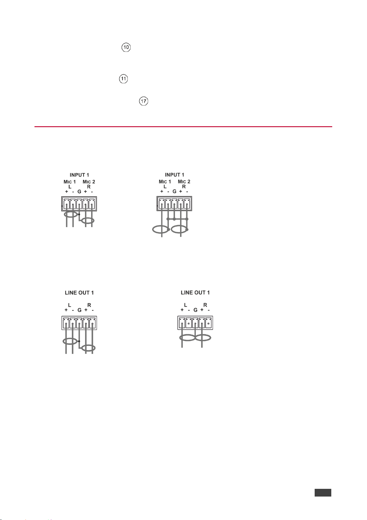
Connecting the Audio Inputs and Outputs
The following are the pinouts for connecting balanced or unbalanced stereo audio sources to
the audio inputs:
Figure 7: Connecting a
Balanced
Stereo Audio Source to the
Input
Figure 8: Connecting an Unbalanced Stereo Audio Source to
the Input
The following are the pinouts for connecting the audio outputs to balanced or unbalanced
stereo audio acceptors:
Figure 9: Connecting the Output to a
Balanced Stereo Audio Acceptor
Figure 10: Connecting the Output to an Unbalanced
Stereo Audio Acceptor
Page 18
Kramer Electronics Ltd.
VS-88UT – Connecting VS-88UT and VS-84UT
16
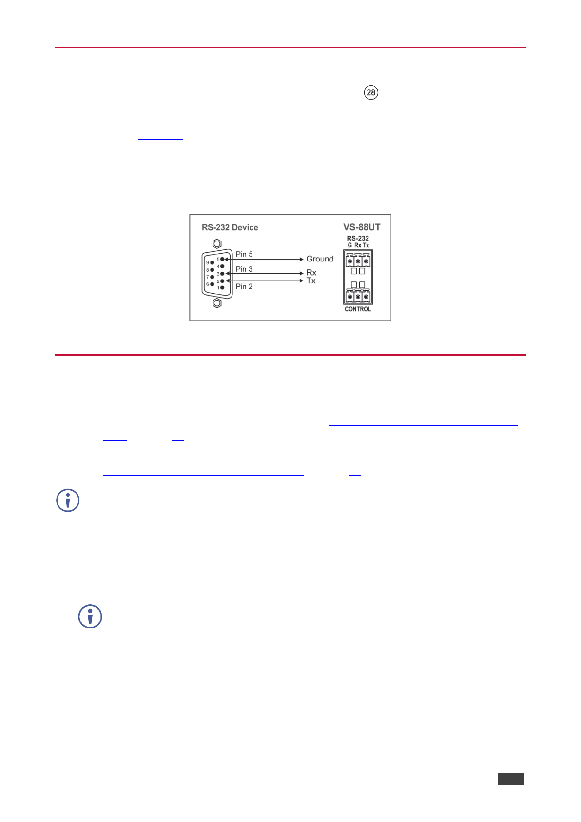
Connecting to VS-88UT via RS-232
You can connect to the VS-88UT via an RS-232 connection using, for example, a PC.
Connect the RS-232 terminal block on the rear panel of the VS-88UT to a PC/controller, as
follows (see Figure 11):
• TX pin to Pin 2
• RX pin to Pin 3
• GND pin to Pin 5
Figure 11: RS-232 Connection
Connecting VS-88UT via the Ethernet Port
You can connect to the VS-88UT via Ethernet using either of the following methods:
• Directly to the PC using a crossover cable (see Connecting the Ethernet Port Directly to
a PC on page 16).
• Via a network hub, switch, or router, using a straight-through cable (see Connecting the
Ethernet Port via a Network Hub or Switch on page 18).
If you want to connect via a router and your IT system is based on IPv6, speak to your IT
department for specific installation instructions.
Connecting the Ethernet Port Directly to a PC
You can connect the Ethernet port of the VS-88UT directly to the Ethernet port on your PC
using a crossover cable with RJ-45 connectors.
This type of connection is recommended for identifying the VS-88UT
with the factory configured default IP address.
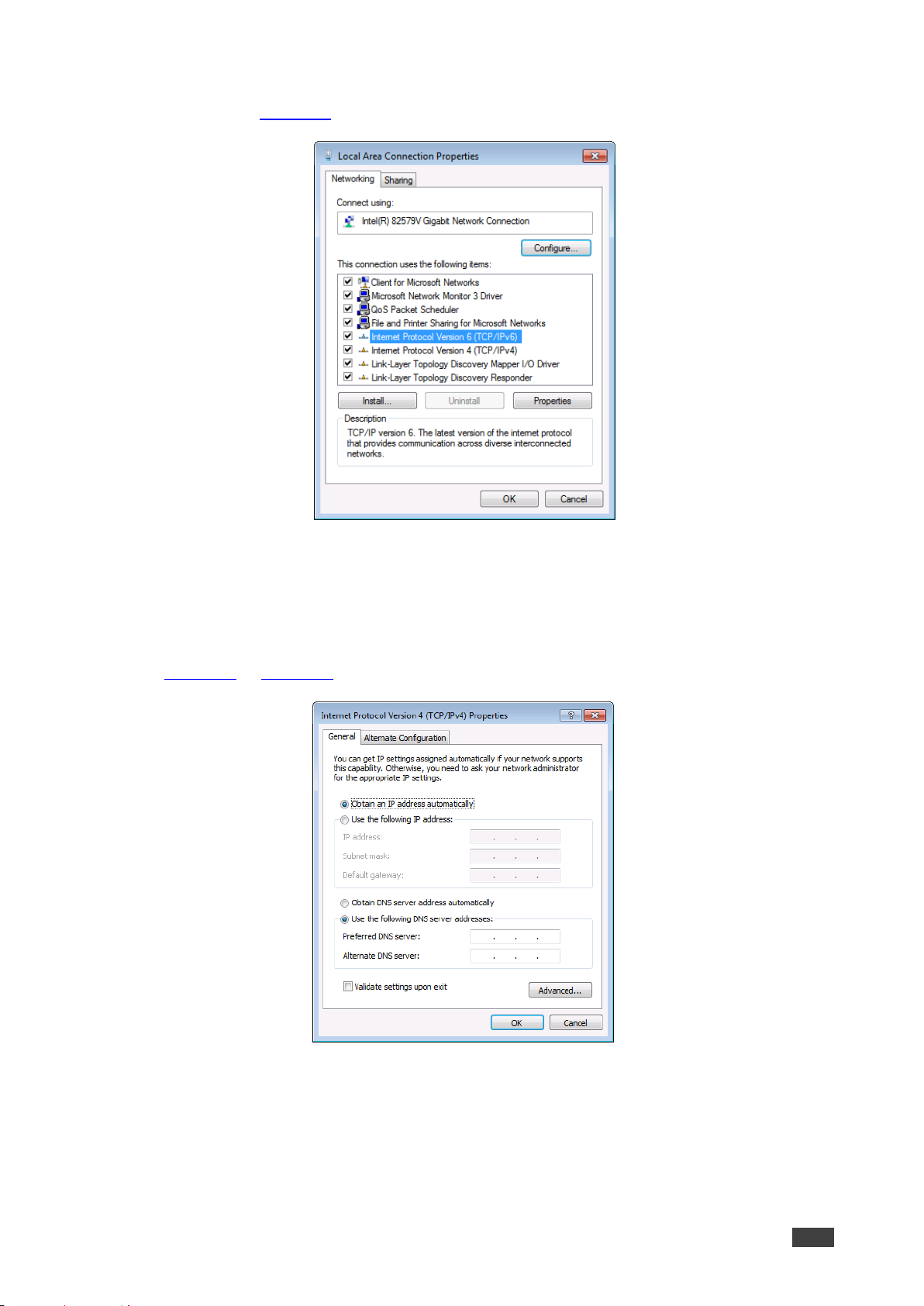
After connecting the VS-88UT to the Ethernet port, configure your PC as follows:
1. Click Start > Control Panel > Network and Sharing Center.
2. Click Change Adapter Settings.
3. Highlight the network adapter you want to use to connect to the device and click Change
settings of this connection.
Page 19
Kramer Electronics Ltd.
VS-88UT – Connecting VS-88UT and VS-84UT
17
The Local Area Connection Properties window for the selected network adapter appears
as shown in Figure 12.
Figure 12: Local Area Connection Properties Window
4. Highlight either Internet Protocol Version 6 (TCP/IPv6) or Internet Protocol Version 4
(TCP/IPv4) depending on the requirements of your IT system.
5. Click Properties.
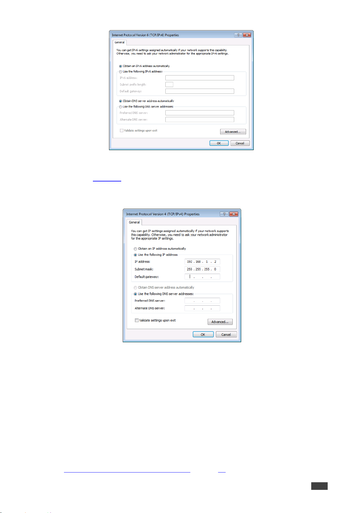
The Internet Protocol Properties window relevant to your IT system appears as shown in
Figure 13 or Figure 14.
Figure 13: Internet Protocol Version 4 Properties Window
Page 20
Kramer Electronics Ltd.
VS-88UT – Connecting VS-88UT and VS-84UT
18
Figure 14: Internet Protocol Version 6 Properties Window
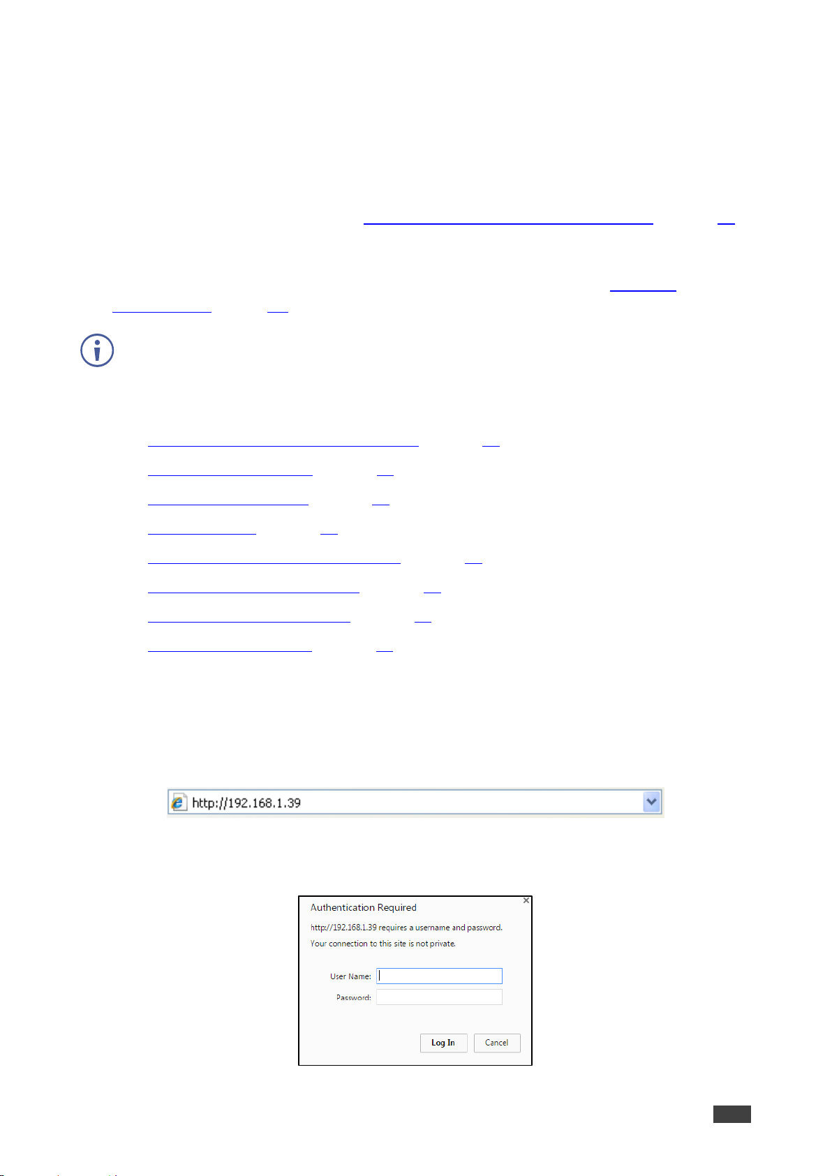
6. Select Use the following IP Address for static IP addressing and fill in the details as
shown in Figure 15.
For TCP/IPv4 you can use any IP address in the range 192.168.1.1 to 192.168.1.255
(excluding 192.168.1.39) that is provided by your IT department.
Figure 15: Internet Protocol Properties Window
7. Click OK.
8. Click Close.
Connecting the Ethernet Port via a Network Hub or Switch
You can connect the Ethernet port of the VS-88UT to the Ethernet port on a network hub or
using a straight-through cable with RJ-45 connectors.
Control Configuration via the Ethernet Port
To control several units via Ethernet, connect the Master unit (Device 1) via the Ethernet port
to the Ethernet port of your PC. Use your PC provide initial configuration of the settings
(see Connecting VS-88UT via the Ethernet Port on page 16).
Page 21
Kramer Electronics Ltd.
VS-88UT – Using the Web Pages
19
Using the Web Pages
The Web pages let you control the VS-88UT via the Ethernet.
Before attempting to connect:
• Perform the procedures in (see Connecting VS-88UT via the Ethernet Port on page 16).
• Ensure that your browser is supported.
The supported operating systems and Web browsers are specified in the Technical
Specifications on page 86.
The VS-88UT and VS-84UT have different input and output numbers but their web pages are
similar. Differences in functionality are described in the following sections.
The VS-88UT Web pages enable performing the following:
• Globally Muting video and audio signals on page 22.
• Defining Global Settings on page 23.
• Routing VS-88UT Ports on page 29.
• Managing EDID on page 60.
• Controlling Devices via the Controller on page 64.
• Configuring Device Automation on page 76.
• Changing the Device Settings on page 78.
• Viewing the About Page on page 85.
To browse the VS-88UT Web pages:
1. Open your Internet browser.
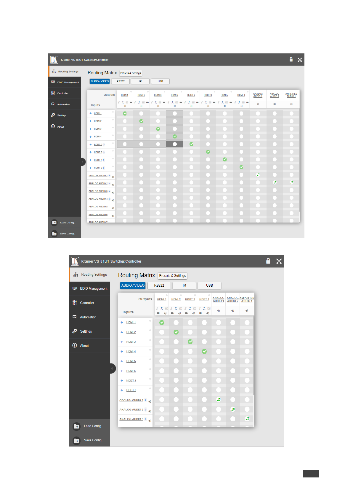
2. Type the IP address of the device in the address bar of your browser. For example, the
default IP address:
Figure 16: Using the Embedded Web pages – Default IP Address
The Authentication window appears: Admin
Figure 17: Using the Embedded Web Pages – Authentication Window
Page 22
Kramer Electronics Ltd.
VS-88UT – Using the Web Pages
20
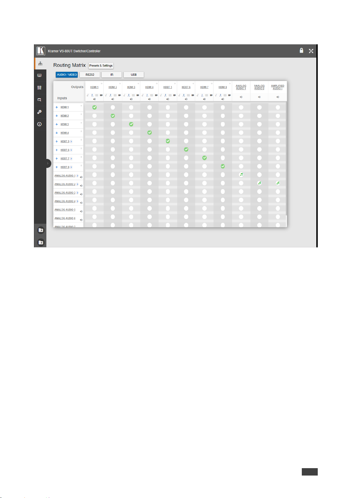
3. Enter the User Name and Password (Admin, Admin by-default) and click OK.
The Routing Settings page appears.
Figure 18: VS-88UT Routing Settings Page with Navigation List on Left
Figure 19: VS-84UT Routing Settings Page with Navigation List on Left
Page 23
Kramer Electronics Ltd.
VS-88UT – Using the Web Pages
21
4. Click the desired Web page or click the arrow to hide the navigation list.
Figure 20: Routing Settings Page – Navigation List Hidden
Page 24
Kramer Electronics Ltd.
VS-88UT – Globally Muting video and audio signals
22
Globally Muting video and audio signals
The Global Mute system is a unique feature that mutes all the video and audio signals to
enable easy integration of the audio system with public alarm systems used for alarms or
other public messages.
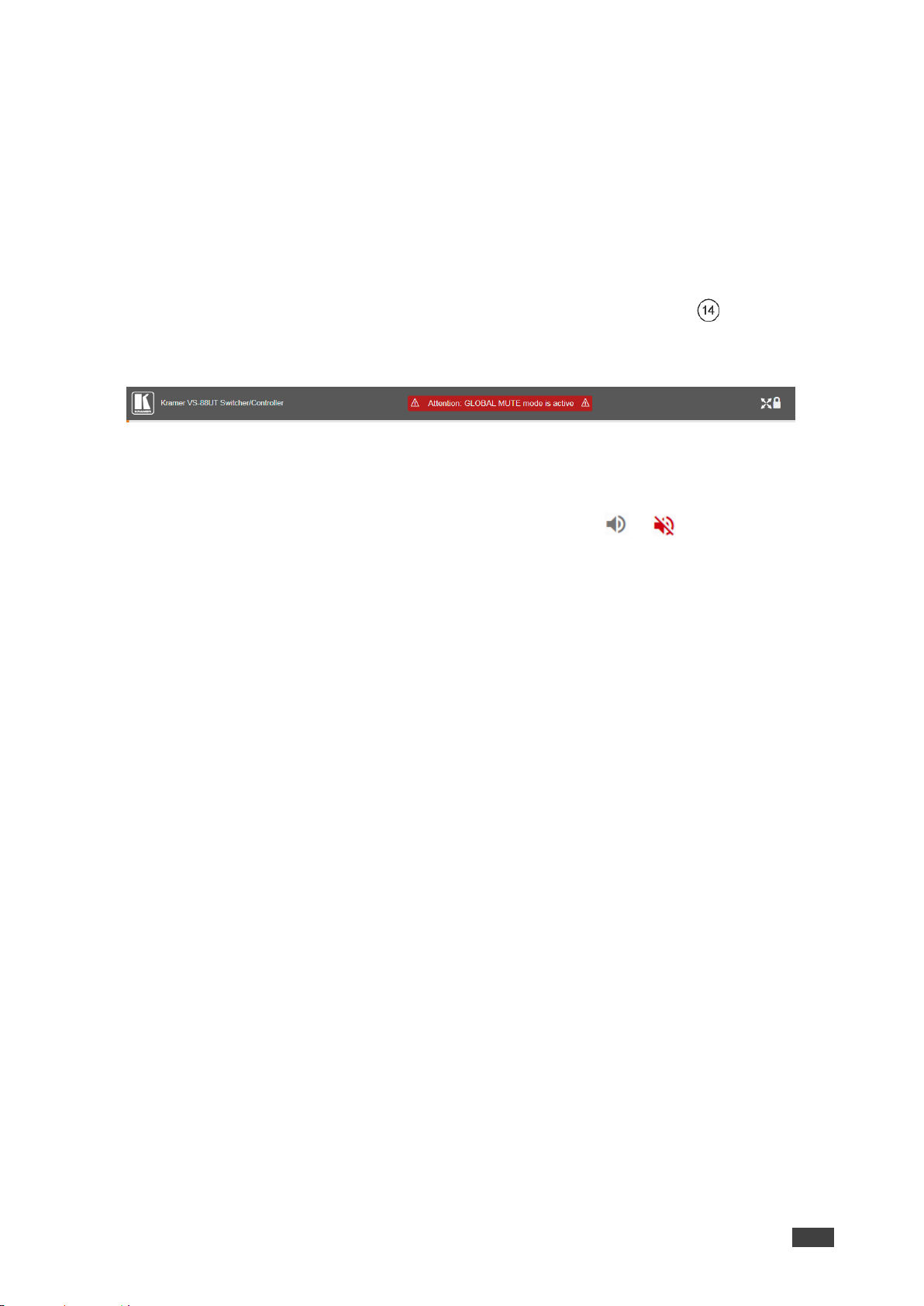
When global mute is triggered via the “REMOTE MUTE” terminal block port , all
HDMI/HDBT and analog outputs are globally muted and a warning note immediately appears
on the web pages heading:
Figure 21: Global Mute Warning
This warning note notifies the administrator that the system is muted due to a REMOTE
MUTE trigger. This trigger is indicated by the warning sign only and does not affect the
display of mute icons in the Routing Settings page. Mute icons ( or ) on the outputs, that
were set before the REMOTE MUTE was triggered, remain unchanged during the REMOTE
MUTE mode and after it ceases.
When the REMOTE MUTE mode is over, the system returns to normal operation and the
warning note disappears.
Page 25
Kramer Electronics Ltd.
VS-88UT – Defining Global Settings
23
Defining Global Settings
Use the Presets & Settings page to set video timeouts, define ports, configure PoE on
HDBT, ports and save and load presets.
To set the video timeouts:
1. In the Navigation pane, click Routing Settings. The Routing Matrix page appears (see
Figure 18).
2. Click Presets & Settings (next to Routing Matrix)).
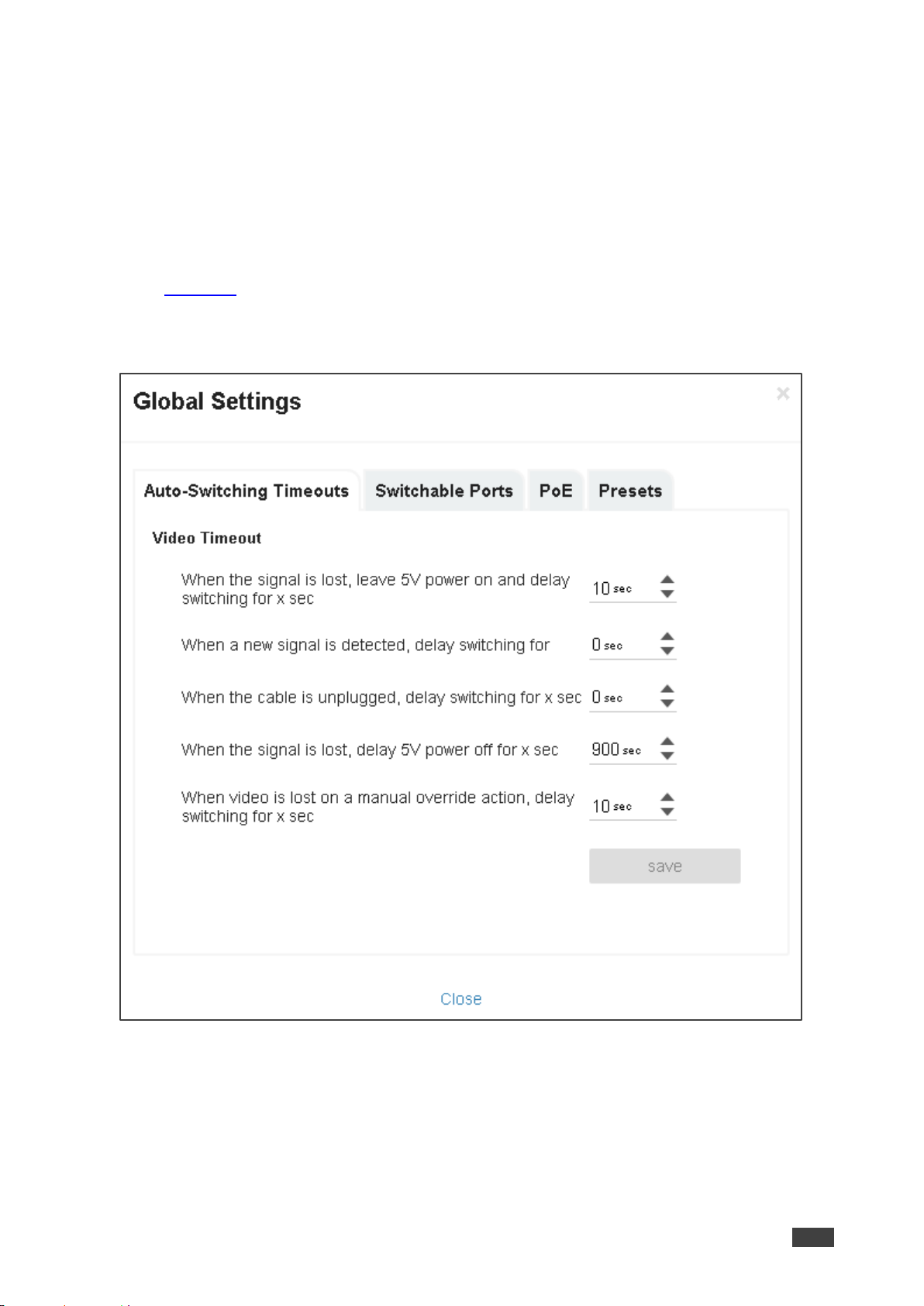
The Global Settings window appears:
Figure 22: Global Settings Window – Auto-Switching Timeouts
3. Click the Auto-Switching Timeouts tab.
4. Set the timeout in seconds for delaying:
▪ Switching upon signal loss when 5V power is left on.
▪ Switching when a new signal is detected.
▪ Switching in case a cable is unplugged.
Page 26
Kramer Electronics Ltd.
VS-88UT – Defining Global Settings
24
▪ 5V power off when the signal is lost.
▪ Switching to the last video input signal after the manual override video input signal is
lost.
5. Click Close.
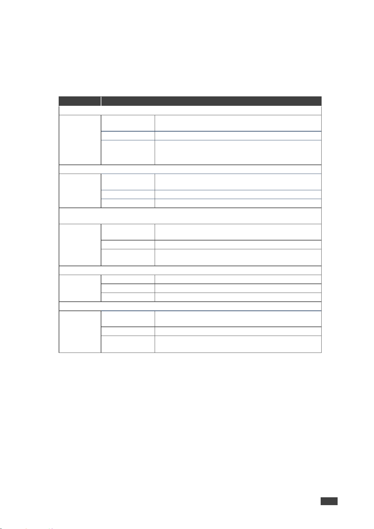
The following table defines the timeout values and conditions:
Timeout
Description, Range (Default) and Conditions
Signal Loss
Description:
When the signal is lost, leave 5V power on and delay
switching for x seconds.
Range (default):
5 to 90 seconds (10 by default).
Conditions:
Signal Loss timeout ≥ 5 seconds
Signal Loss timeout < Output Inactivity
Signal Loss timeout < manual-override mode inactivity
Signal Gain
Description:
When a new signal is detected, delay switching for x
seconds.
Range (default)
0 to 90 seconds (0 by default).
Conditions
No conditions
Input
Unplug
Description:
When the cable is unplugged, delay switching for x
seconds.
Range (default)
0 to 90 seconds (0 by default).
Conditions
Input Unplug timeout ≤ Output inactivity
Input unplug timeout ≤ manual-override mode inactivity
Output Inactivity
Description:
When the signal is lost, delay 5V power off for x seconds.
Range (default)
5 to 60000 seconds (900 by default).
Conditions
Output Inactivity timeout > Input Unplug
Manual-Override Mode Inactivity
Description:
When video is lost on a manual override action, delay
switching for x seconds.
Range (default)
5 to 90 seconds (10 by default).
Conditions
Manual-Override Mode Inactivity timeout ≥ Signal Loss
Manual-Override Mode Inactivity timeout ≥ Input Unplug
To set the switchable ports:
1. In the Navigation pane, click Routing Settings. The Routing Matrix page appears.
2. Click Global Settings (on the top left side).
The Global Settings window appears.
3. Click Switchable Ports tab.
The Switchable Ports tab appears.
Page 27
Kramer Electronics Ltd.
VS-88UT – Defining Global Settings
25
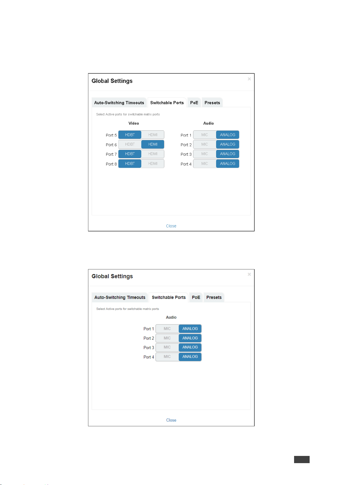
4. Do the following
▪ VS-88UT: For video input ports 5 to 8, select either the HDBT or HDMI input and for
audio input ports 1 to 4, select either ANALOG or MIC input.
The changes are immediately reflected the Routing Settings page.
Figure 23: VS-88UT Global Settings Window – Switchable Ports Tab
▪ VS-84UT: For audio input ports 1 to 4, select either ANALOG or MIC input.
The changes are immediately reflected the Routing Settings page.
Figure 24: VS-88UT Global Settings Window – Switchable Ports Tab
5. Click Close.
Page 28
Kramer Electronics Ltd.
VS-88UT – Defining Global Settings
26
To set configure PoE power support on HDBT ports:
1. In the Navigation pane, click Routing Settings. The Routing Matrix page appears.
2. Click Global Settings (on the top left side). The Global Settings window appears.
3. Click the PoE tab. The PoE configuration tab appears.
4. Do the following:
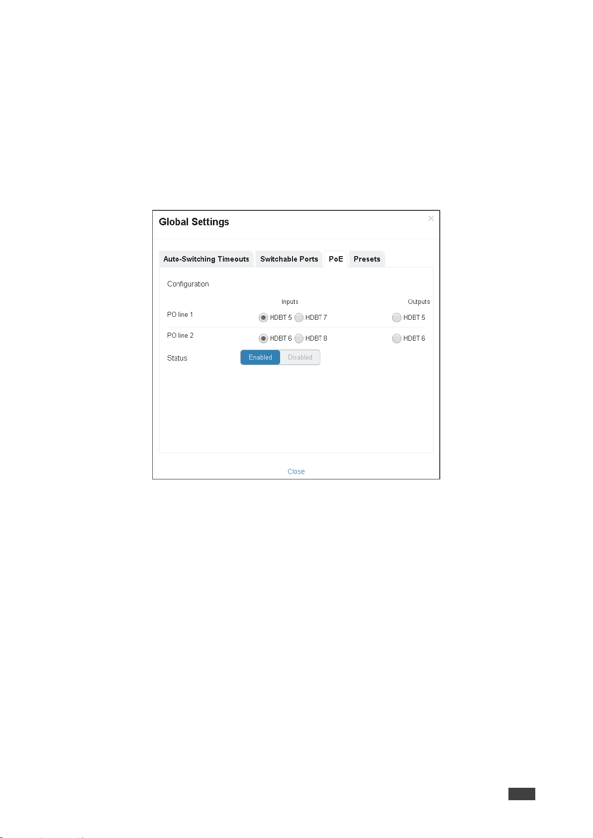
▪ VS-88UT: Click one radio button on each PO line to select the ports supporting PoE.
You can select one port on each PO line (for example HDBT 5 input for PO line 1
and HDBT 6 input for PO line 2).
Figure 25: VS-88UT Global Settings Window – HDBT POE Support Tab
Page 29
Kramer Electronics Ltd.
VS-88UT – Defining Global Settings
27
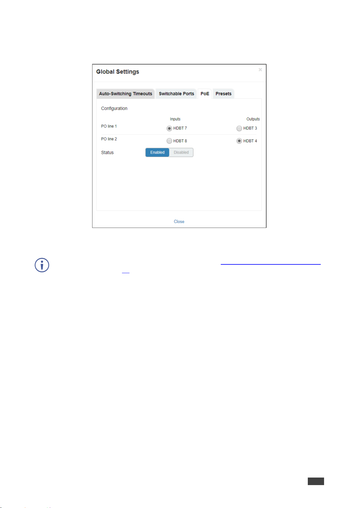
▪ VS-84UT: Click one radio button on each PO line to select the ports supporting PoE.
You can select one port on each PO line (for example HDBT 7 input for PO line 1
and HDBT 4 output for PO line 2).
Figure 26: VS-84UT Global Settings Window – HDBT POE Support Tab
5. Enable or disable HDBT PoE support.
PoE status is displayed in the HDBT settings page (see Changing HDBT/HDMI and HDBT
Port Settings on page 41).
6. Click Close.
Page 30
Kramer Electronics Ltd.
VS-88UT – Defining Global Settings
28
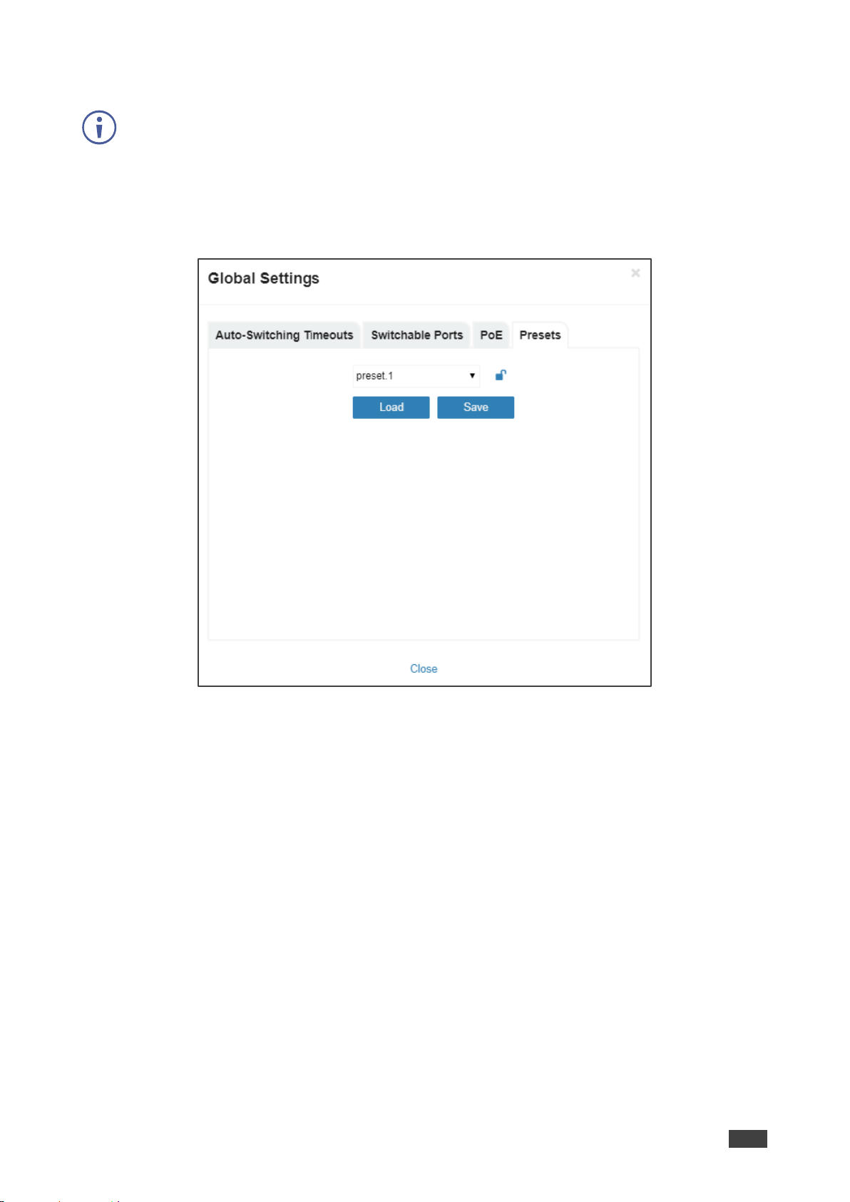
To load or save a preset (the current device settings):
A preset saves the device configuration, excluding Network settings, EDID files and Maestro
configuration.
1. In the Navigation pane, click Routing Settings. The Routing Matrix page appears.
2. Click Global Settings (on the top left side). The Global Settings window appears.
3. Click the Presets tab. The Presets tab appears:
Figure 27: Global Settings Window – Presets Tab
4. Select a preset (from 1 to 8)
5. Do any of the following:
▪ To save a preset, click Save.
▪ To load an existing preset, click Load.
Page 31
Kramer Electronics Ltd.
VS-88UT – Routing VS-88UT Ports
29
Routing VS-88UT Ports
This section describes how to basically route an A/V input to any of the outputs.
By default, input and output ports are set to audio-follow-video.
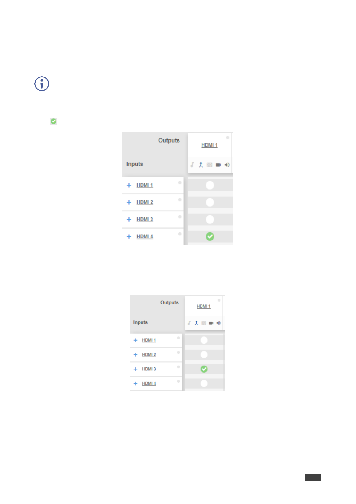
The Routing Matrix page displays the current routing status. For example, in Figure 28 the
HDMI 4 input is currently routed to the HDMI 1 output as indicated by the green routing button
( ).
Figure 28: Routing Settings Page – Input to Output Example
To route an input to an output, click a white routing button within the matrix. For example, to
route the HDMI 3 input to the HDMI 1 output, click the routing button connecting them in the
matrix:
Figure 29: Routing Settings Page – Routing an Input to an Output
Page 32

Kramer Electronics Ltd.
VS-88UT – Routing VS-88UT Ports
30
Hover over a port to view its switching status (HDMI 3 audio and video inputs are routed to
HDMI 1 and HDMI 2 outputs):
Figure 30: Routing Settings Page – Viewing the Switching Status
In the same way, you can route all the port types in the matrix if connected by a routing
button.
To define each of the ports in the matrix and perform advanced routing operations, see
Defining Port Settings on page 30.
Defining Port Settings
This section describes how to route the ports (audio, video, RS-232, IR and USB) in the
matrix and define the port settings.
The Routing Settings page enables the following:
• Setting Input HDMI Port Parameters on page 31.
• Setting Input HDBT/HDMI or HDBT Input Port Parameters on page 39.
• Setting Analog Audio Input Port Parameters on page 46.
• Setting the HDMI and HDBT Output Parameters on page 51.
• Setting Analog and Amplified Audio Output Parameters on page 55.
• Setting and Routing the RS-232 Ports on page 56.
• Setting and Routing IR Ports on page 58.
• Setting and Routing the USB Ports on page 58.
While almost all the VS-88UT port settings examples also apply to VS-84UT (even though
the number of inputs and outputs may be different) there are some exceptions which are
described separately throughout this section.
Page 33
Kramer Electronics Ltd.
VS-88UT – Routing VS-88UT Ports
31
Setting Input HDMI Port Parameters
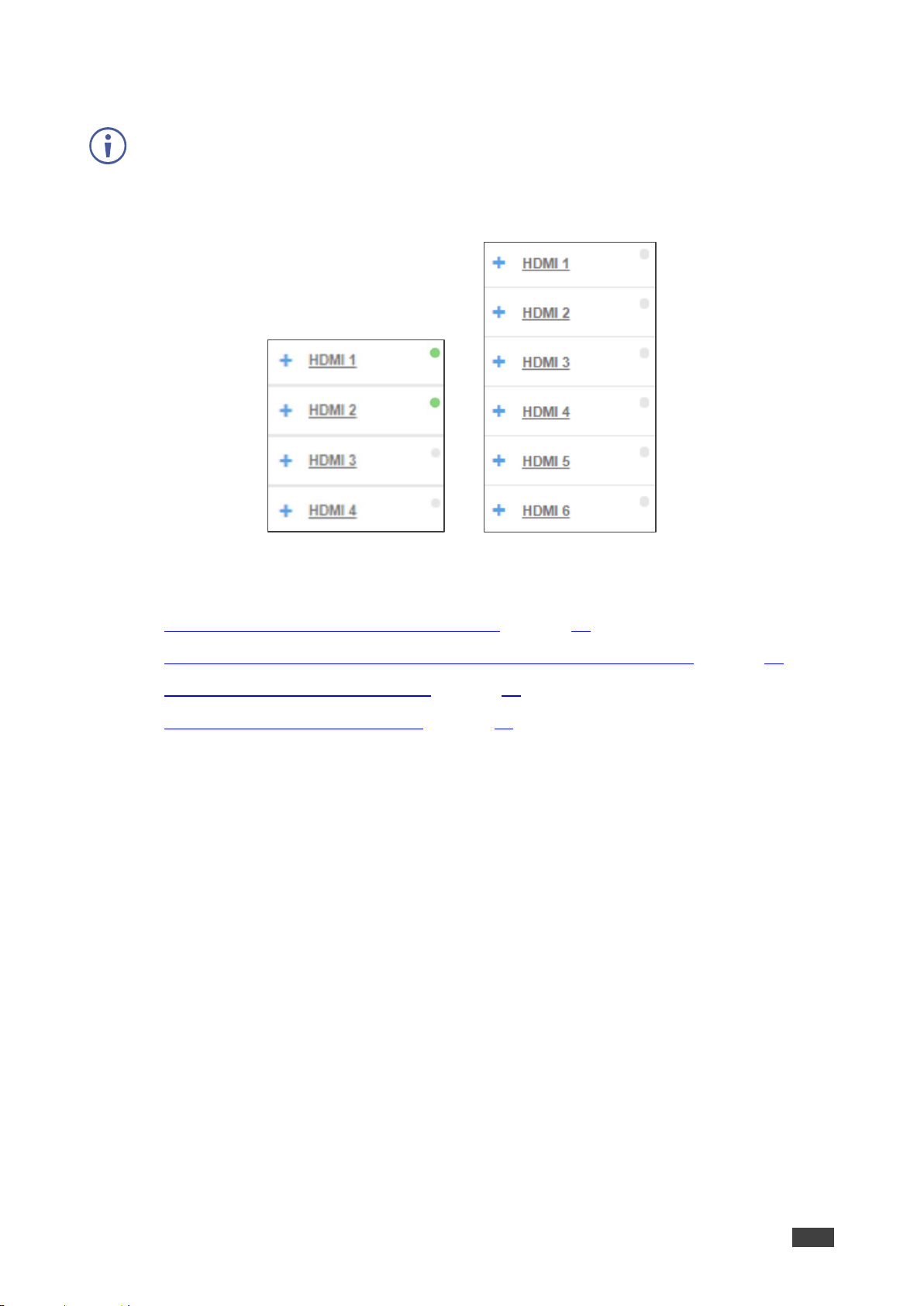
VS-88UT has four HDMI (1 to 4) inputs and VS-84UT has six HDMI (1 to 6) inputs (as well as
two HDMI outputs).
The green indication indicates a valid signal on the input.
Figure 31: Port Settings – HDMI Input Ports
The following functions are available:
• Viewing and Routing A/V Signals Separately on page 32.
• Routing A/V Signals in the Audio-Follow-Video and Breakaway Modes on page 33.
• Changing HDMI Input Port Settings on page 35.
• Selecting the HDMI Input Follower on page 36.
Page 34
Kramer Electronics Ltd.
VS-88UT – Routing VS-88UT Ports
32
Viewing and Routing A/V Signals Separately
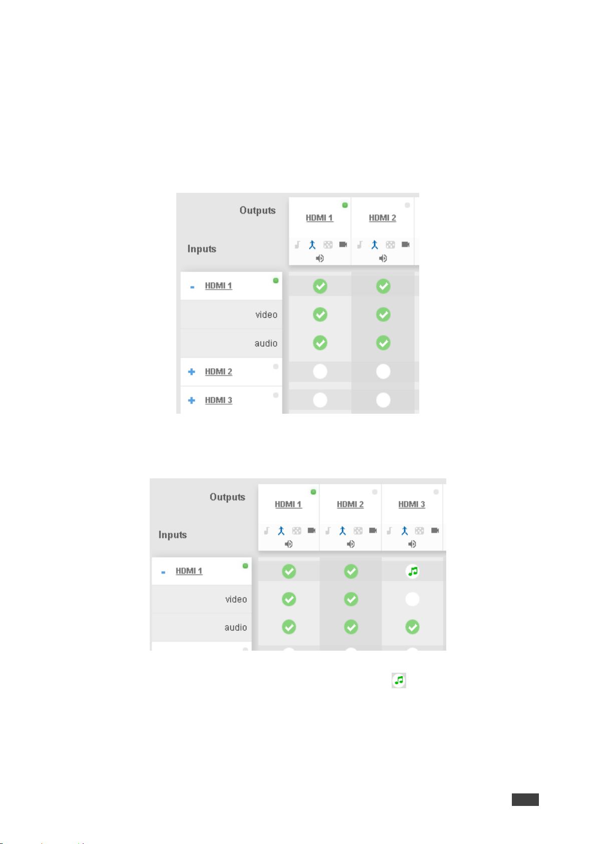
To view the video and audio signals separately:
• Click Routing Settings page. The Routing Matrix page opens.
• Click + beside the input port name.
• The HDMI port line displays the status of each signal separately.
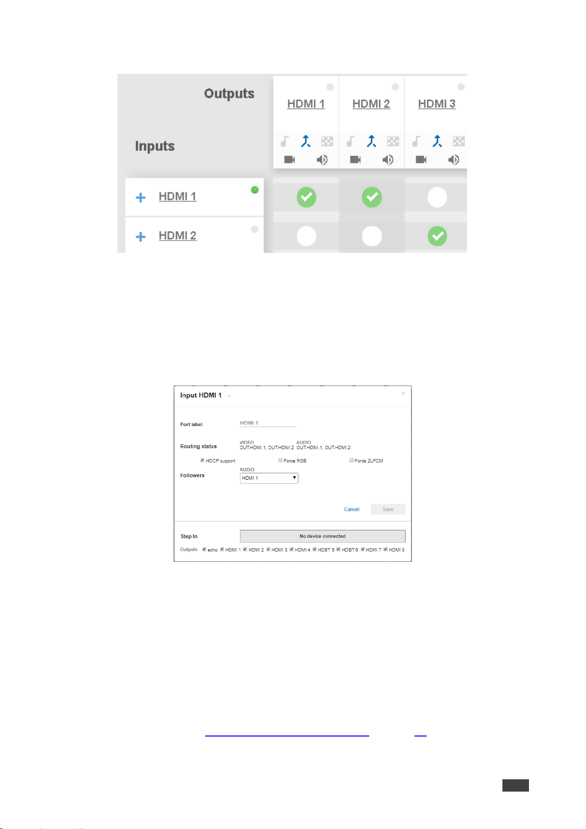
The following example shows that the HDMI 1 input (both audio and video signals) is
routed to output HDMI 1 and HDMI 2.
Figure 32: Routing Settings Page – HDMI Input Ports
• Click the HDMI 1 input audio button under output HDMI 3.
The audio signal only is routed from HDMI 1to HDMI 3
Figure 33: Routing Settings Page – Routing the audio signal only
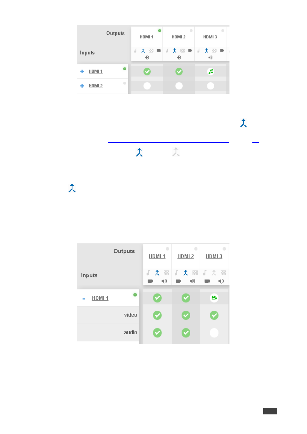
• Click – to close the separate-signals view. The audio icon appears under the HDMI
3 output.
Page 35
Kramer Electronics Ltd.
VS-88UT – Routing VS-88UT Ports
33
Figure 34: Routing Settings Page – Separate Audio Routing
Routing A/V Signals in the Audio-Follow-Video and Breakaway Modes
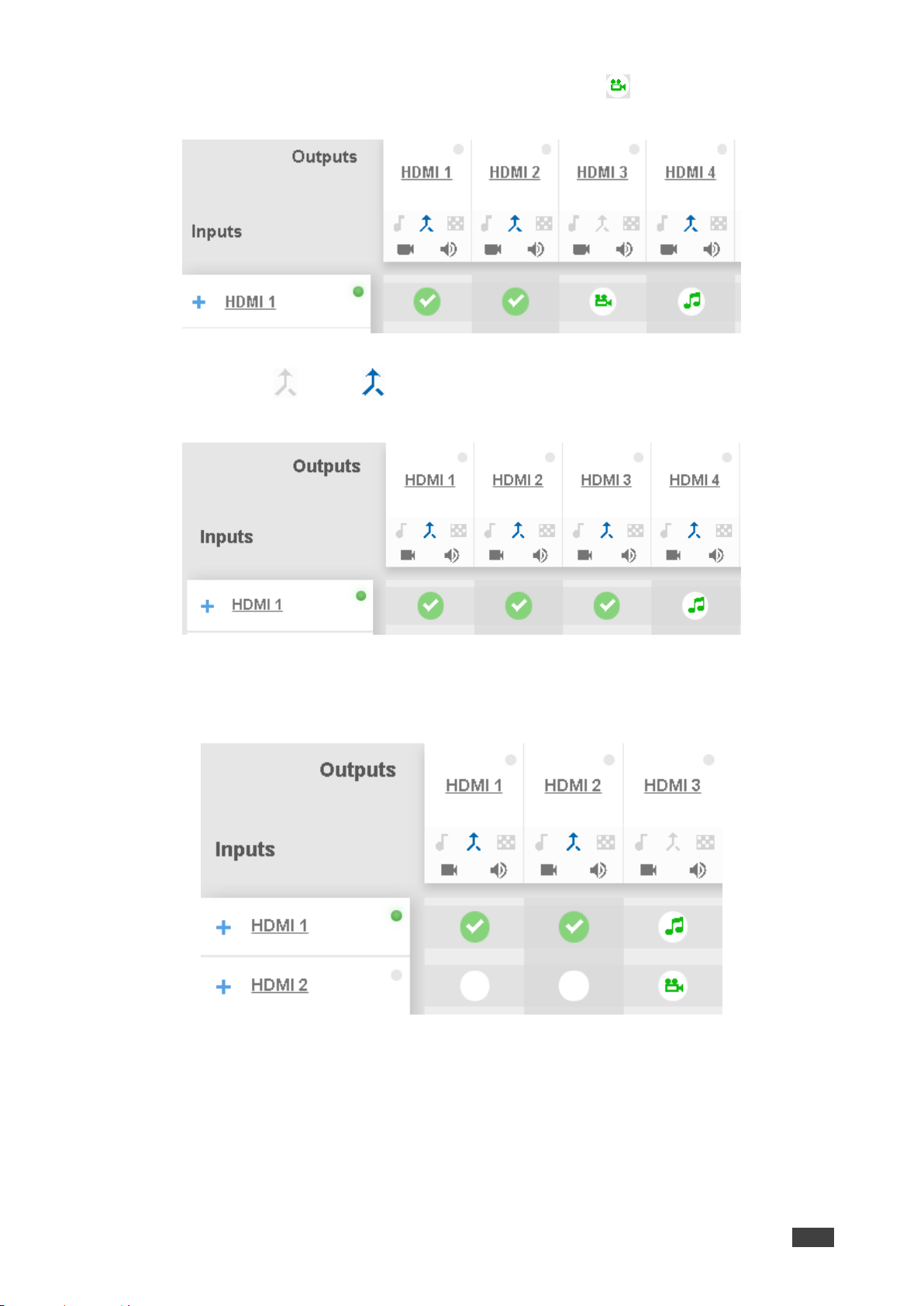
By default, all the outputs are set to the Audio-Follow-Video mode (AFV) mode . When
routing an input to an output or only a video signal to an output, both audio and video signals
appear on the output (see Setting the HDMI and HDBT Output Parameters on page 51).
Click the AFV icon to toggle between (AFV) and (Breakaway) modes.
To route an input to an output in the breakaway mode:
• Click Routing Settings page. The Routing Matrix page opens.
• Click on an output (HDMI 3 in this example).
The AFV icon is deselected and that output is now in the Breakaway mode.
• Click + beside the HDMI 1 input port name.
• Click Video Input 1 to output 3
The audio signal no longer follows the video signal, therefore when routing a video
signal, the audio signal does not follow.
Figure 35: Routing Settings Page – Routing the Video Signal Only
Page 36
Kramer Electronics Ltd.
VS-88UT – Routing VS-88UT Ports
34
• Click – to close the separate-signals view. The audio icon appears under the HDMI
3 output.
Figure 36: Routing Settings Page – Routing in the AFV Mode
Once you toggle back to (AFV) the audio signal is immediately routed to the HDMI
3 output.
Figure 37: Routing Settings Page – Routing in the Breakaway Mode
In the breakaway mode you can also route the audio from one source and the video from
another:
Figure 38: Routing Settings Page – Separate A/V Signal Sources in the Breakaway Mode
Page 37
Kramer Electronics Ltd.
VS-88UT – Routing VS-88UT Ports
35
Once the AFV is back on, the input 2 audio signal follows the video signal.
Figure 39: Routing Settings Page – A/V Signal Sources in the AFV Mode
Changing HDMI Input Port Settings
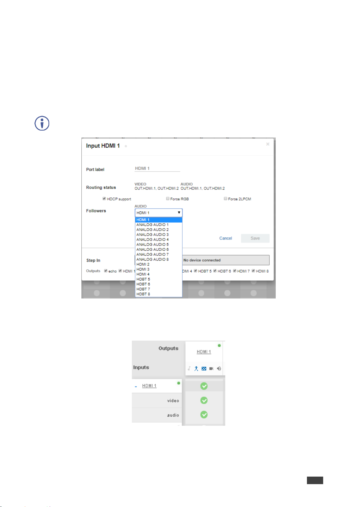
To define the HDMI port:
1. Click Routing Settings page. The Routing Matrix page opens.
2. Click HDMI.
The following window appears:
Figure 40: Routing Settings Page – Input HDMI Settings
3. Perform the following actions, as required:
▪ Change the Port Label name.
▪ View the Routing Status.
▪ Check/uncheck HDCP Support.
▪ Check/uncheck Force RGB.
▪ Check/uncheck Force 2LPCM.
▪ Open the AUDIO drop-down box and select the audio signal to follow the HDMI
video signal (see Selecting the HDMI Input Follower on page 36).
Page 38
Kramer Electronics Ltd.
VS-88UT – Routing VS-88UT Ports
36
▪ Set the Step-in outputs to which the video signal will be routed in case the step-in
button is pressed on the is input.
4. Click Save.
Selecting the HDMI Input Follower
When selecting a follower to the input signal, this follower is routed together with the input
signal, to the selected output. When routing HDMI signals, you can define the AUDIO signal
to follow the video signal.
The follower signal is applied in the next routing step.
Figure 41: Routing Settings Page – HDMI 1 Input Audio Followers
For example, when routing input HDMI 1 to the HDMI 1 output, HDMI 1 audio is routed to the
output.
Figure 42: Routing Settings Page – Input HDMI 1 Routed to Output HDMI 1
Page 39
Kramer Electronics Ltd.
VS-88UT – Routing VS-88UT Ports
37
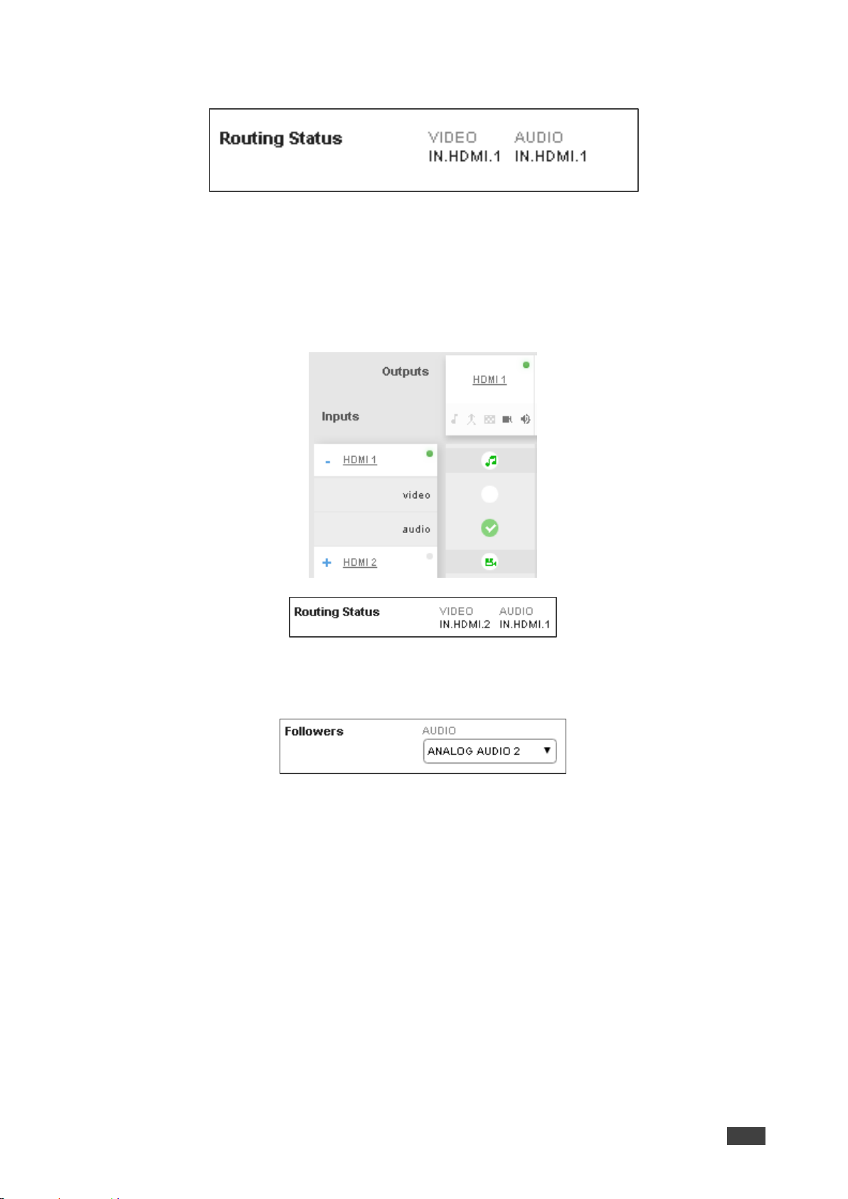
Click the HDMI 1 output to see the settings page, and view the routing status:
Figure 43: Routing Settings Page – HDMI 1 Output Routing Status
The routing status fits the settings on the HDMI 1 input.
When setting the HDMI 1 output to the breakaway mode, upon the next routing step (for
example, HDMI 2 routed to HDMI 1, the audio source remains HDMI 1 and the video source
is HDMI 2
Figure 44: Routing Settings Page – HDMI 2 Input to HDMI 1 Routing Status
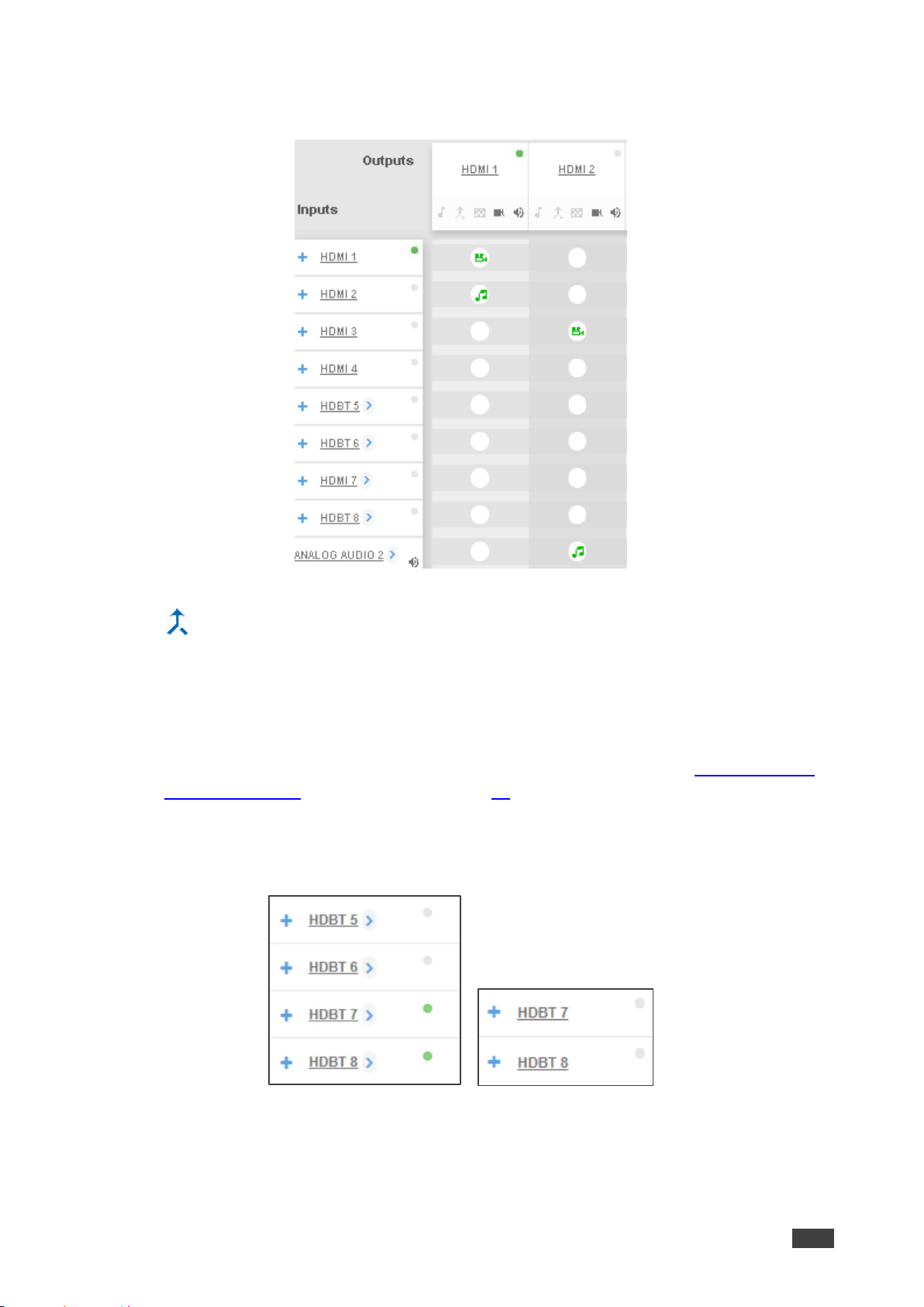
In the following example ANALOG AUDIO 2 is set as the audio follower for input HDMI 1:
Figure 45: Routing Settings Page – HDMI 1 Input, Analog Audio 2 Follows
Page 40
Kramer Electronics Ltd.
VS-88UT – Routing VS-88UT Ports
38
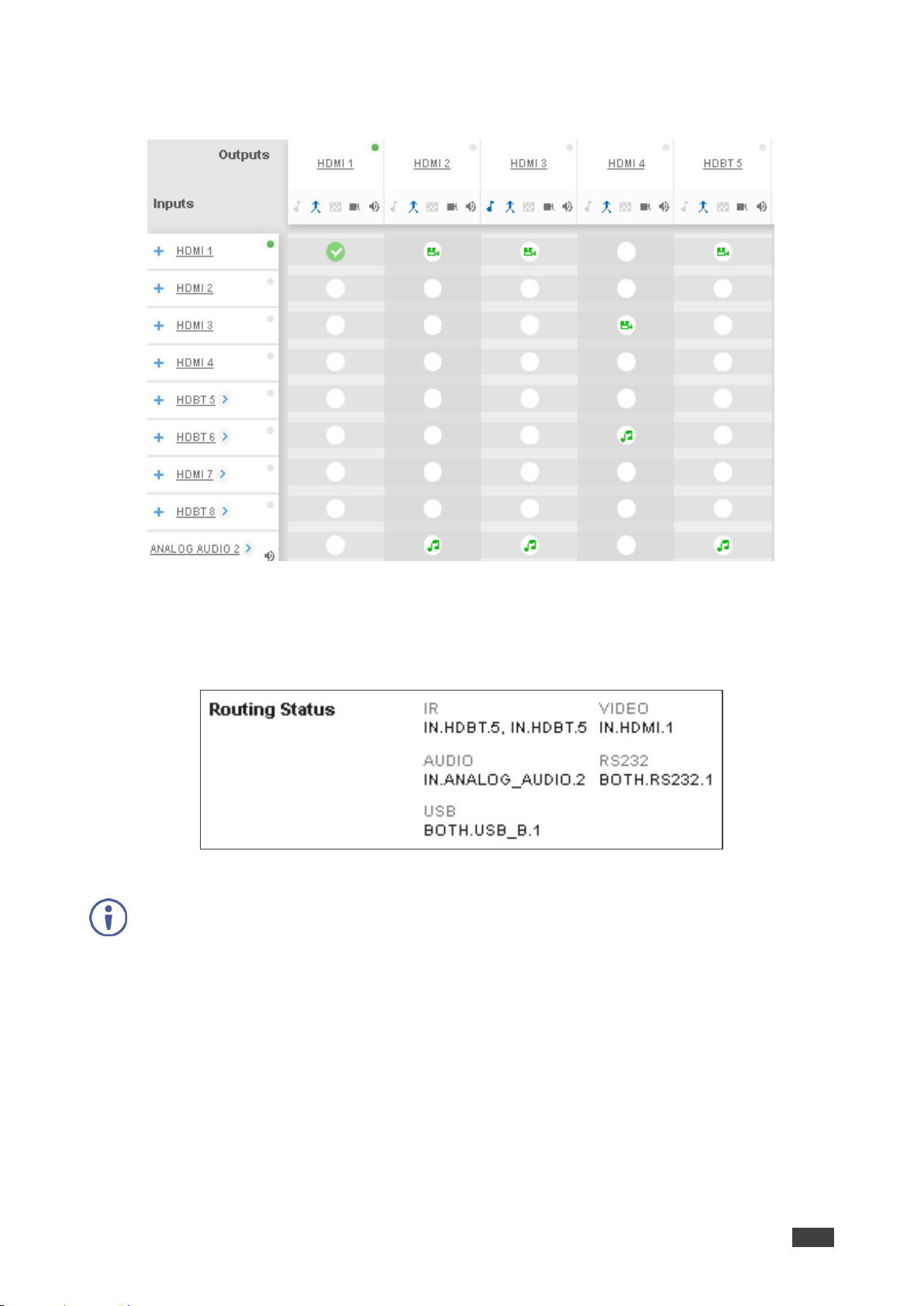
In the AFV mode, whenever HDMI 1 is routed to an output the audio source will be ANALOG
AUDIO 2:
Figure 46: Routing Settings Page – Routing HDMI 1 Routed to Several Outputs
For the HDMI 1, HDMI 2, HDMI 3 and HDBT 5, ANALOG AUDIO 2 is the audio source.
Output Routing Status shows ANALOG AUDIO 2 as the source:
Figure 47: Routing Settings Page – HDBT 5 Output Routing Status
For HDBT outputs, the Routing Status shows other signal followers (for example, HDBT 5 input IR
follows the video signal).
Page 41
Kramer Electronics Ltd.
VS-88UT – Routing VS-88UT Ports
39
In the breakaway mode, when routing the HDMI 1 input to HDMI 2 output, ANALOG AUDIO 2
is still the audio source:
Figure 48: Routing Settings Page – HDBT 6 Output Routing Status
Click to return to the AFV mode. When routing the HDMI 1 input to HDMI 2 output, the
audio source is ANALOG AUDIO 2 once again.
Setting Input HDBT/HDMI or HDBT Input Port Parameters
The HDBT ports on each device have a slightly different function:
• VS-88UT has four ports that can be set as HDBT or HDMI inputs, see VS-88UT only –
Setting the Port to HDBT or HDMI on page 40.
• VS-84UT has two dedicated HDBT ports (HDBT 7 and HDBT 8).
The green indication indicates a valid signal on the input.
Figure 49: Port Settings – HDBT Input Ports
Page 42
Kramer Electronics Ltd.
VS-88UT – Routing VS-88UT Ports
40
The following functions are available:
• VS-88UT only – Setting the Port to HDBT or HDMI on page 40.
• Viewing and Routing HDMI/HDBT and HDBT A/V Signals Separately on page 40.
• Changing HDBT/HDMI and HDBT Port Settings on page 41.
VS-88UT only – Setting the Port to HDBT or HDMI
To set the port to HDBT or HDMI:
1. Click Routing Settings page. The Routing Matrix page opens.
2. Click next to the port name.
3. Select the desired port:
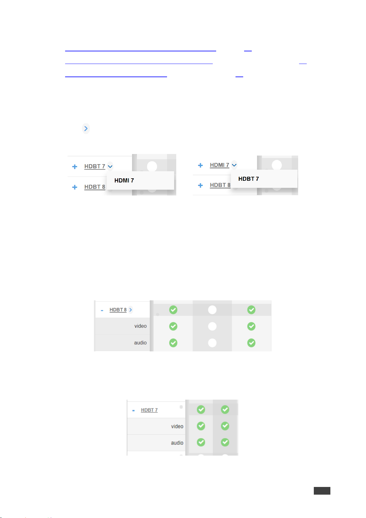
Figure 50: Port Settings – Selecting HDBT or HDMI Input Ports
Viewing and Routing HDMI/HDBT and HDBT A/V Signals Separately
To view the video and audio signals separately:
• Click Routing Settings page. The Routing Matrix page opens.
• Click + beside the port name.
• For VS-88UT, the HDMI/HDBT port line displays the status of each signal separately.
The following example shows that the HDBT 8 input (both audio and video signals) is
routed to HDMI 1 and HDMI 3 outputs.
Figure 51: VS-88UT Port Settings – HDBT Input Ports
• For VS-84UT, the HDBT port line displays the status of each signal separately.
The following example shows that the HDBT 7 input (both audio and video signals) is
routed to HDMI 1 and HDMI 2 outputs.
Figure 52: VS-84UT Port Settings – HDBT Input Ports
• Click - to close the separate-signals view.
Page 43
Kramer Electronics Ltd.
VS-88UT – Routing VS-88UT Ports
41
Changing HDBT/HDMI and HDBT Port Settings
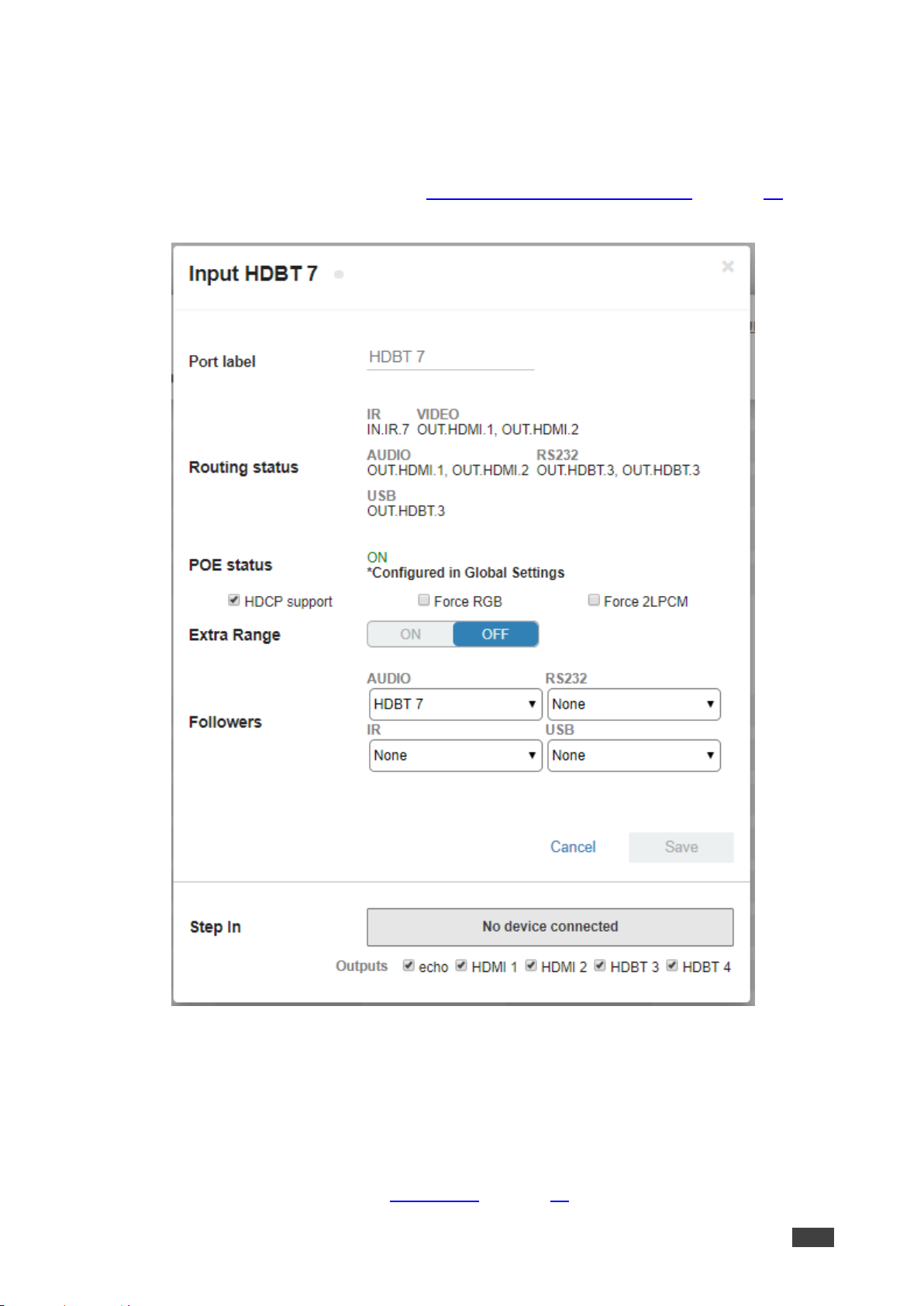
To define the HDBT/HDMI HDBT port:
1. Click Routing Settings page. The Routing Matrix page opens.
2. Click HDBT (HDMI is described in Changing HDMI Input Port Settings on page 35).
The following window appears:
Figure 53: Routing Settings Page – Input HDBT Settings
Each setting retains the switching state (followers are specific for the HDMI and HDBT port).
3. Perform the following actions, as required:
▪ Change the Port Label name.
▪ View the Routing Status.
▪ View the POE status (see POE Status on page 42).
Page 44
Kramer Electronics Ltd.
VS-88UT – Routing VS-88UT Ports
42
▪ Check/uncheck HDCP Support.
▪ Check/uncheck Force RGB.
▪ Check/uncheck Force 2LPCM.
▪ Set Extra Range to ON or OFF.
▪ Select Followers drop-down boxes for AUDIO, RS-232, IR, and USB signals.
The selected port signals will now follow the video signal (see Selecting the HDBT
Input Followers on page 43).
▪ Set Step-In outputs to which the video signal will be routed in case the step-in button
is pressed on this input (see Setting the Step-in Status on the HDBT Ports
on page 57).
4. Click Save.
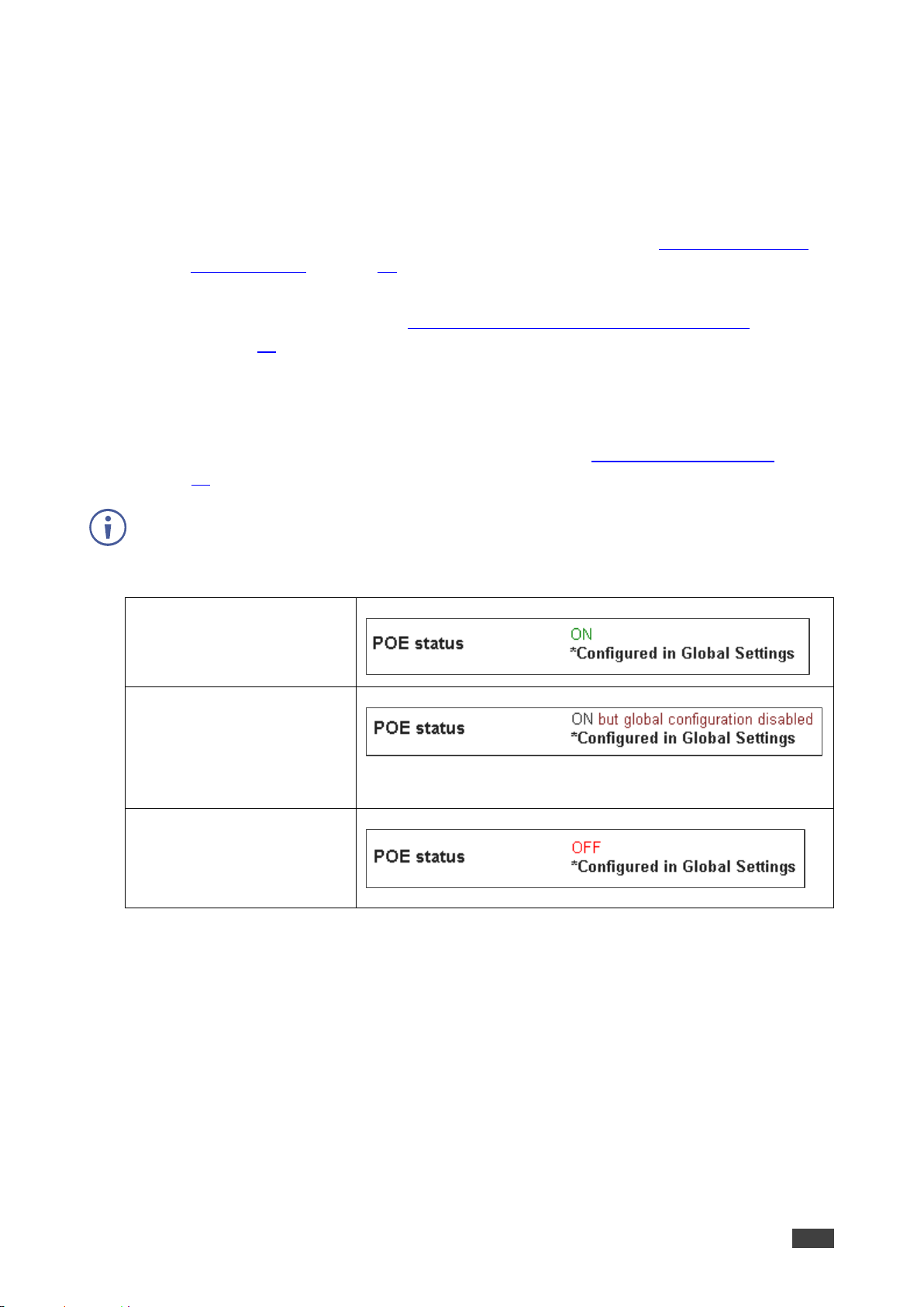
POE Status
POE on the HDBT ports is configured via global settings (see Defining Global Settings
on page 23).
POE status appears on the HDBT settings page when the port is set to HDBT.
The following POE status messages appear:
POE is configured and
enabled on this port.
POE is configured on this port
but is currently not active since
PoE support in Global Settings
is disabled
POE is not configured on this
port but can be configured via
Global Settings.
Page 45
Kramer Electronics Ltd.
VS-88UT – Routing VS-88UT Ports
43
Selecting the HDBT Input Followers
When selecting a follower to the input signal, this follower is routed together with the input
signal, to the selected output. When routing HDBT signals, you can define AUDIO, RS-232,
IR, and USB signals to follow the video signal.
The follower signals are applied in the next routing step.
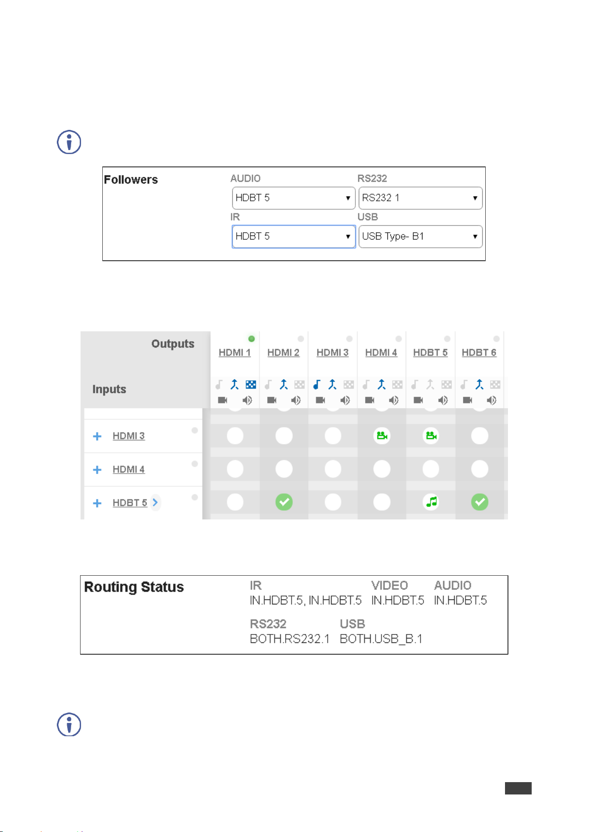
Figure 54: Routing Settings Page – Input HDBT 5 Followers Settings
For example, when routing input HDBT 5 to the HDBT 6 output, HDBT 5 audio is routed to the
output.
Figure 55: Routing Settings Page – Input HDBT 5 Routed to Output HDBT 6
Click the HDBT 6 output to see the settings page, and view the routing status:
Figure 56: Routing Settings Page – HDBT 6 Output Routing Status
The routing status fits the settings on the HDBT 5 input.
When routing in the AFV mode, all the followers, follow the video routing.
Page 46
Kramer Electronics Ltd.
VS-88UT – Routing VS-88UT Ports
44
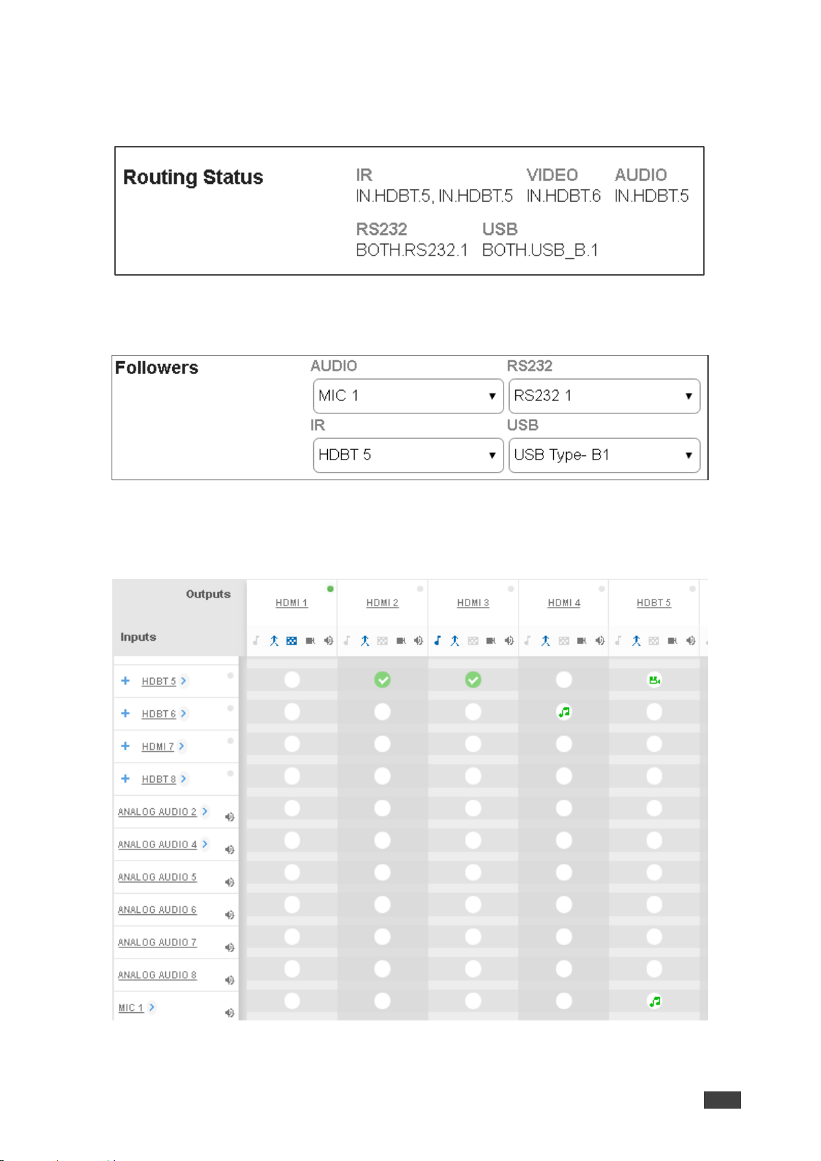
When setting the HDBT 6 output to the breakaway mode, upon the next routing step (for
example, HDBT 6 routed to HDBT 6, the routing status will remain the same (except for the
video signal):
Figure 57: Routing Settings Page – HDBT 6 Input to HDBT 6 Output Routing Status
In the following example MIC 1 is set as the audio follower for input HDBT 5:
Figure 58: Routing Settings Page – HDBT 5 Input, MIC 1 Audio follows
In the AFV mode, whenever HDBT 5 is routed to an output (for example, HDBT 5) the audio
source will be MIC 1:
Figure 59: Routing Settings Page –Routing HDBT 5 Input to HDBT 6 Output
Page 47
Kramer Electronics Ltd.
VS-88UT – Routing VS-88UT Ports
45
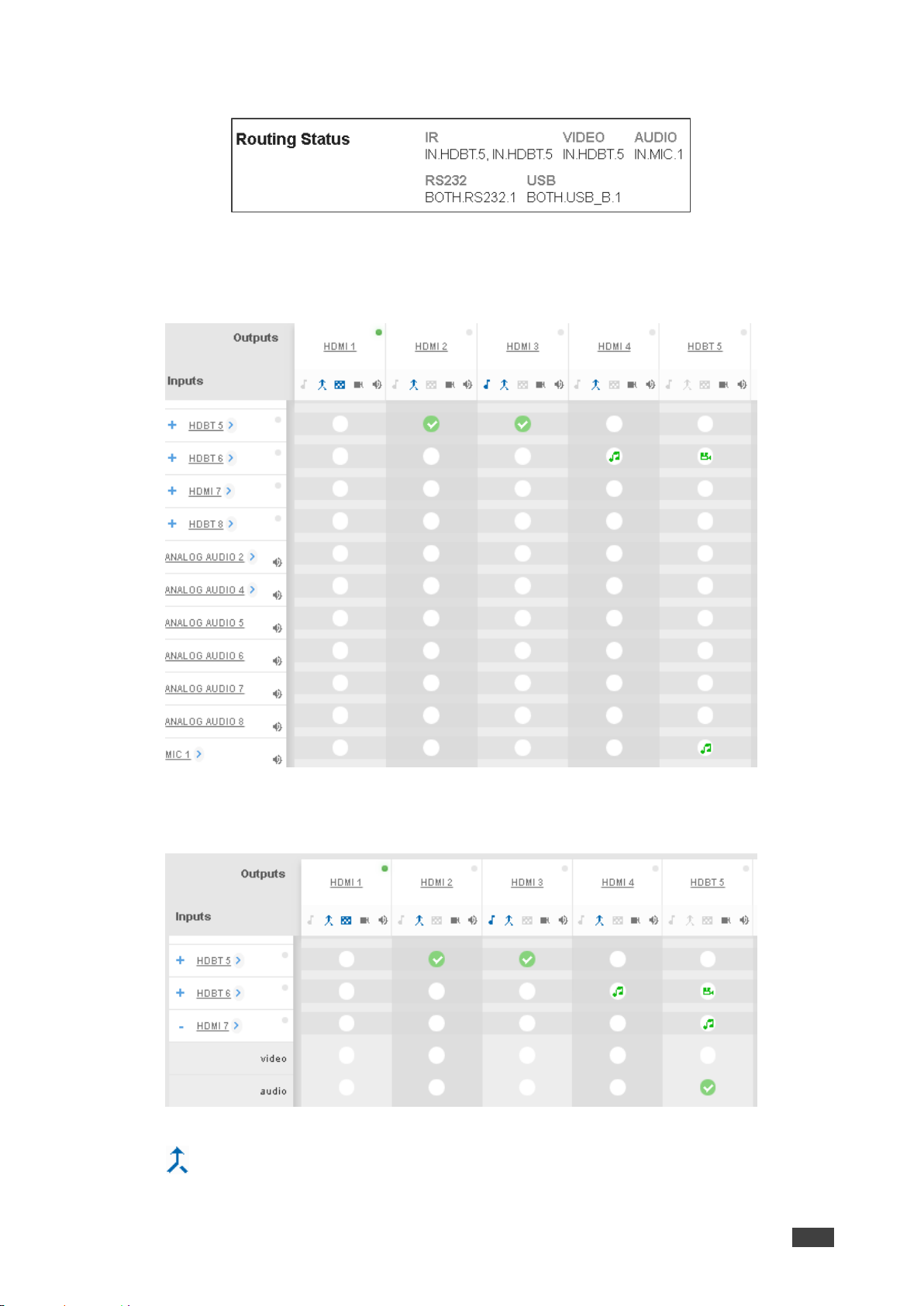
The HDBT 5 output routing status shows MIC 1 as the source:
Figure 60: Routing Settings Page – HDBT 6 Output Routing Status
In the breakaway mode, when routing the HDBT 6 input to HDBT 5 output MIC 1 is still the
audio source:
Figure 61: Routing Settings Page – HDBT 6 Output Routing Status
Then, when setting HDBT 7 input as audio source, MIC 1 is no longer the audio source:
Figure 62: Routing Settings Page – HDBT 5 Output in the Breakaway Mode
Click to return to the AFV mode. When routing the HDBT 5 input to HDBT 5 output, the
audio source is MIC 1 once again.
Page 48
Kramer Electronics Ltd.
VS-88UT – Routing VS-88UT Ports
46
Setting Analog Audio Input Port Parameters
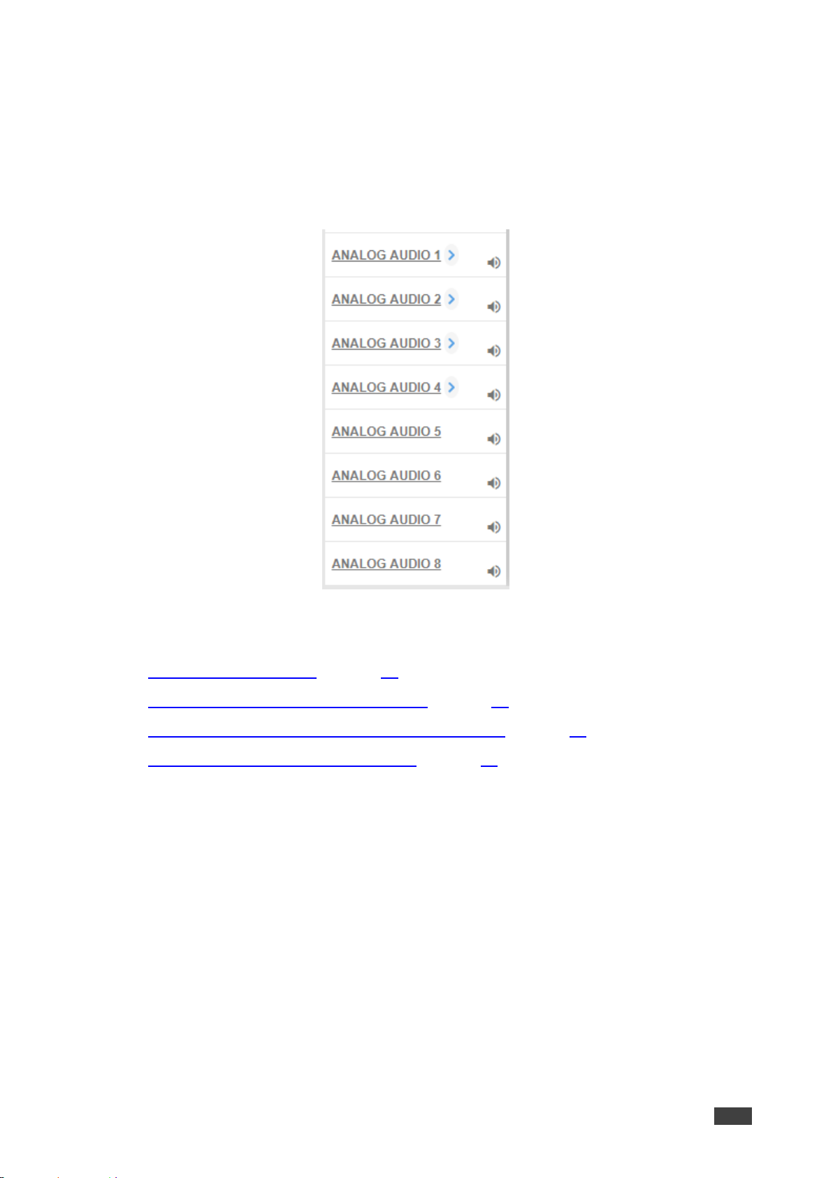
VS-88UT has eight stereo analog audio inputs: 1 to 4 are balanced inputs and 5 to 8 are
unbalanced inputs.
Each of the balanced analog inputs (1 to 4) can also function as microphone inputs (MIC 1 to
MIC 8); inputs 5 to 8 function as unbalanced analog inputs.
Figure 63: Port Settings – Analog Audio Input Ports
The following functions are available:
• Setting the Input Volume on page 47.
• Changing the Analog Audio Port Settings on page 47.
• Setting the Port to Analog Input or Two Microphones on page 48.
• Changing the Microphone Port Settings on page 50.
Page 49
Kramer Electronics Ltd.
VS-88UT – Routing VS-88UT Ports
47
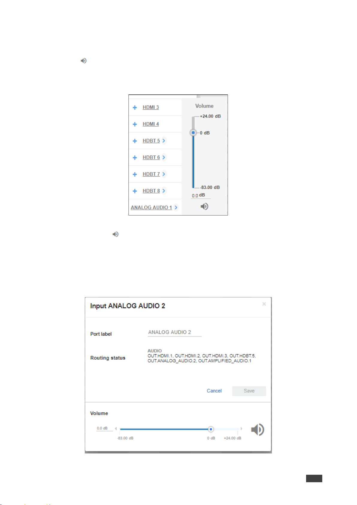
Setting the Input Volume
To set the input volume:
1. Click .
The volume slider window appears.
2. Set the volume (set to 0dB by default).
Figure 64: Port Settings –Setting Analog Audio Level
3. If required, click to mute the input.
Changing the Analog Audio Port Settings
To set the ANALOG AUDIO Port
1. Click ANALOG AUDIO.
The following window appears:
Figure 65: Routing Settings Page – Input ANALOG AUDIO Settings
Page 50
Kramer Electronics Ltd.
VS-88UT – Routing VS-88UT Ports
48
2. Perform the following actions, as required:
▪ Change the Port Label name.
▪ View the Routing Status.
▪ Set the Volume.
3. Click Save.
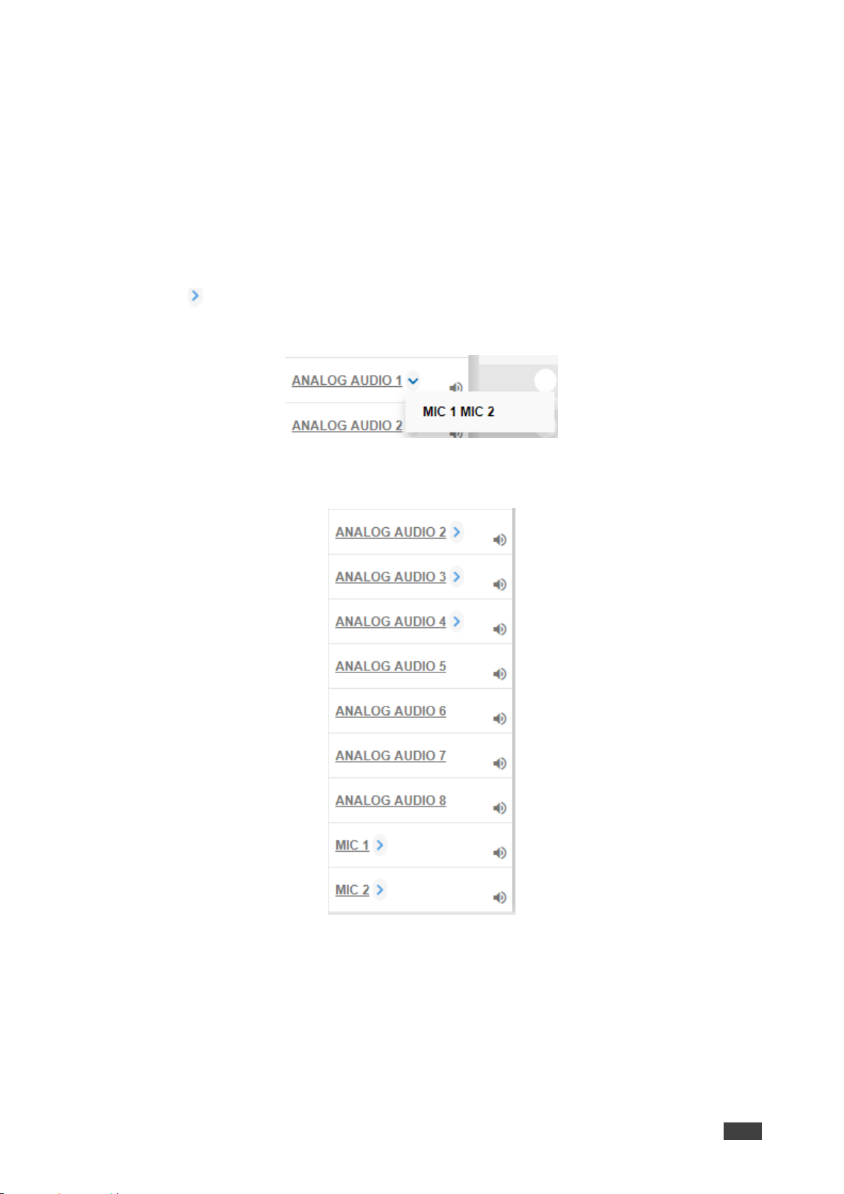
Setting the Port to Analog Input or Two Microphones
To set a port to function as an analog input or as two microphone inputs:
1. Click next to the port name.
2. Set ANALOG AUDIO 1 (for example) to MIC 1 MIC 2 desired port.
Figure 66: Port Settings – Selecting Analog Audio or Mic Input Ports
The ANALOG AUDIO 1 is replaced by MIC 1 and MIC 2 ports:
Figure 67: Port Settings – Setting MIC Ports
In the same way ANALOG AUDIO 2 (MIC 3 and MIC 4), ANALOG AUDIO 3 (MIC 5 and
MIC 6) and ANALOG AUDIO 4 (MIC 7 and MIC 8) can interchange.
Page 51
Kramer Electronics Ltd.
VS-88UT – Routing VS-88UT Ports
49
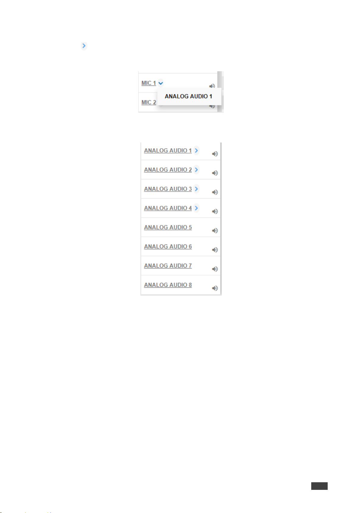
To set a MIC port to function as an analog input:
1. Click next to one of the MIC ports.
2. Set MIC 1 (for example) to ANALOG AUDIO 1.
Figure 68: Port Settings – Selecting MIC to ANALOG AUDIO
ANALOG AUDIO 1 is restored:
Figure 69: Port Settings – Setting MIC Ports
Page 52
Kramer Electronics Ltd.
VS-88UT – Routing VS-88UT Ports
50
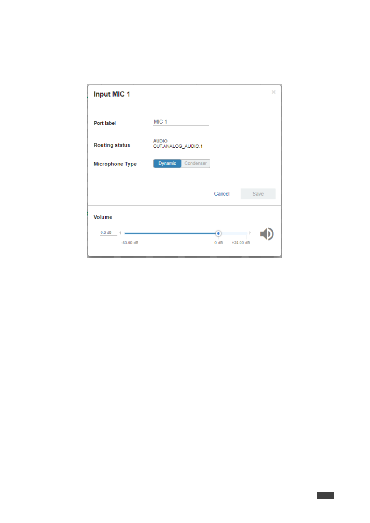
Changing the Microphone Port Settings
To change the MIC Port settings:
1. Click MIC.
The following window appears:
Figure 70: Routing Settings Page – Input MIC Settings
Each setting (ANALOG or MIC) retains the switching state (followers are specific for the
defined port).
2. Perform the following actions, as required:
▪ Change the Port Label name.
▪ View the Routing Status.
▪ Set the Microphone Type to Dynamic or Condenser.
▪ Set Microphone Volume.
3. Click Save.
Page 53
Kramer Electronics Ltd.
VS-88UT – Routing VS-88UT Ports
51
Setting the HDMI and HDBT Output Parameters
VS-88UT has six HDMI outputs (1 to 4 and 7 to 8) and two HDBT outputs (5 to 6); VS-84UT
has two HDMI outputs (1 to 2) and two HDBT (3 to 4) outputs.
The green indication indicates a valid signal on the output.
Figure 71: Port Settings – HDMI and HDBT Output Ports
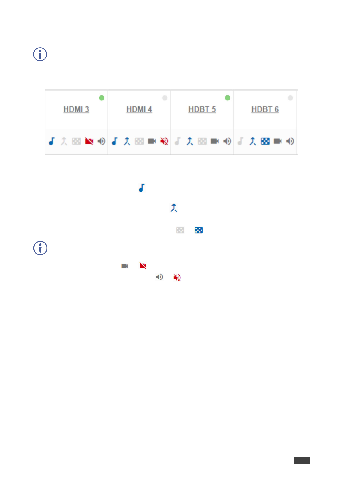
The HDMI icons enable performing the following actions:
• Enabling audio only mode ( ): only audio is routed through the output (a black pattern
screen is displayed and 5V cut off is disabled).
• Enabling/Disabling audio follow video ( ): both audio and video are routed through the
output.
• Select a pattern to display on the output ( or if a pattern is selected).
If a pattern is selected on an output and an input is routed to that output, the pattern is disabled and
the routed video signal appears on the output.
• Turn HDMI on or off ( or ).
• Mute or unmute the audio signal ( or ).
The following functions are available:
• Changing the HDMI Output Port Settings on page 52.
• Changing the HDBT Output Port Settings on page 53.
Page 54
Kramer Electronics Ltd.
VS-88UT – Routing VS-88UT Ports
52
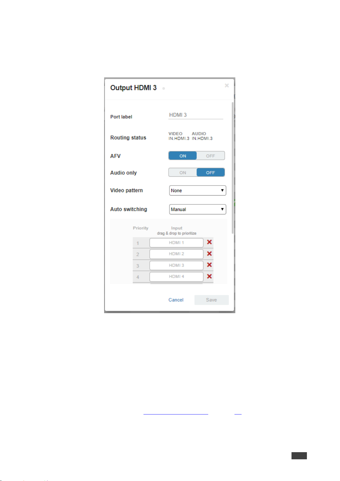
Changing the HDMI Output Port Settings
To set the HDMI output port:
1. Click HDMI.
The following window appears:
Figure 72: Routing Settings Page – Output HDMI Settings (Scroll down to view all inputs)
2. Perform the following actions, as required:
▪ Change the Port Label name.
▪ View the Routing Status.
▪ Set AFV to ON or OFF.
▪ Set Audio only to ON or OFF.
▪ Select a Video Pattern.
▪ Open the Auto Switching drop-down box and select Manual, Priority or Last
Connected switching, see Auto Switching Feature on page 54.
3. Click Save.
Page 55
Kramer Electronics Ltd.
VS-88UT – Routing VS-88UT Ports
53
Changing the HDBT Output Port Settings
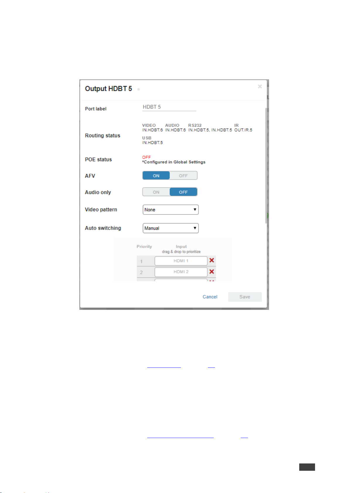
To set the HDBT output port:
1. Click HDBT.
The following window appears:
Figure 73: Routing Settings Page – HDBT Output Settings (Scroll down to view all inputs)
2. Perform the following actions, as required:
▪ Change the Port Label name.
▪ View the Routing Status.
▪ View the POE status (see POE Status on page 42).
▪ Set AFV to ON or OFF.
▪ Set Audio only to ON or OFF.
▪ Check/uncheck AFV.
▪ Select a Video Pattern.
▪ Open the Auto Switching drop-down box and select Manual, Priority or Last
Connected switching, see Auto Switching Feature on page 54.
3. Click Save.
Page 56
Kramer Electronics Ltd.
VS-88UT – Routing VS-88UT Ports
54
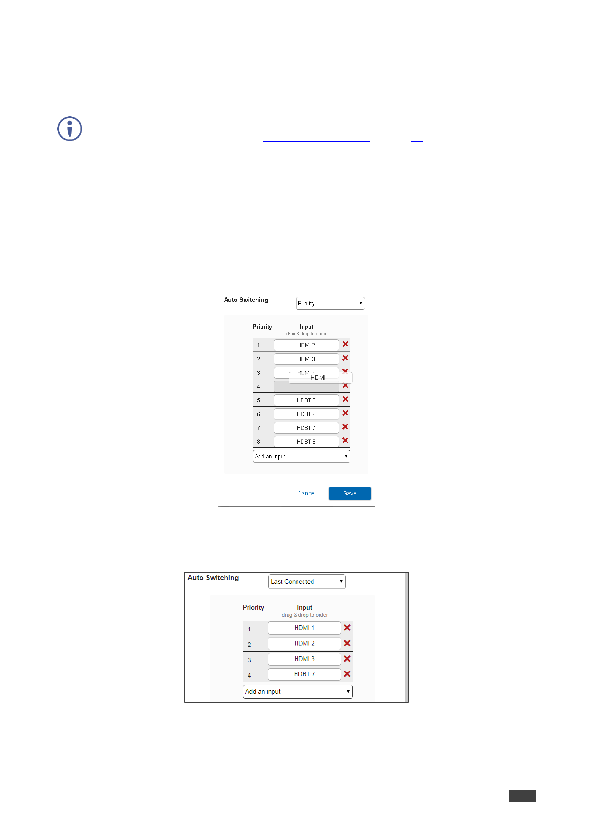
Auto Switching Feature
For HDMI and HDBT outputs set Auto Switching to Manual (the default), Priority or Last
Connected.
In both Last Connected and Priority modes, when the input signal sync is lost (but the cable is not
removed) there is a default delay (see Defining Global Settings on page 23) before another input is
automatically selected. When an input cable is removed, there is a delay before automatic switching
takes place.
In the Manual mode Video Lost timeouts are disabled.
To use Auto Switching:
1. Open the HDMI/HDBT settings window.
2. If Auto Switching is set to Priority or Last Connected, you can do the following:
▪ Drag and drop an input to set the priority order:
Figure 74: Routing Settings Page –Priority Setup
▪ Delete input/s to exclude them from the priority list.
To add a deleted input, click Add an Input drop-down list and select the input/s.
Figure 75: Routing Settings Page – HDMI/HDBT Priority List
3. Click Save.
Page 57
Kramer Electronics Ltd.
VS-88UT – Routing VS-88UT Ports
55
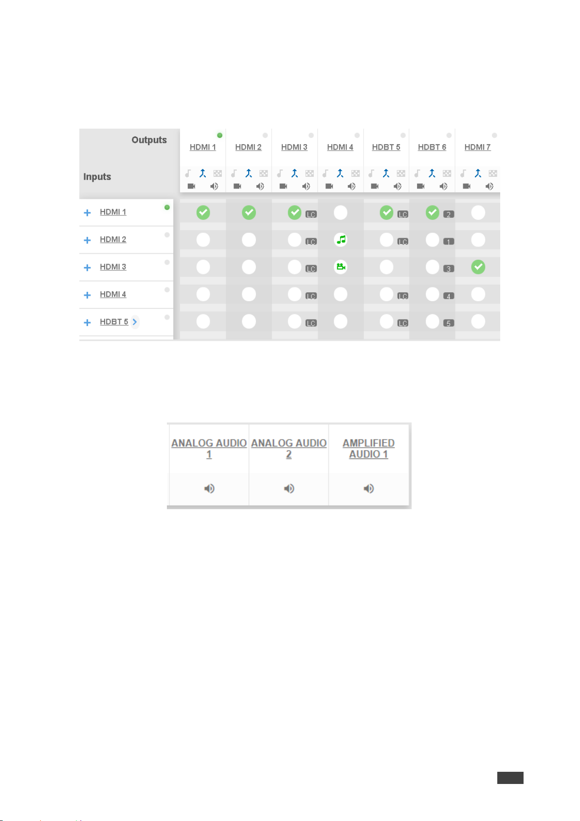
Priority and Last Connected settings are indicated in the Routing Settings page as follows:
• The priority order numbers appear under output HDBT 6.
• Last Connected (LC) appears under outputs HDMI 3 and HDBT 5 (where input HDMI 3
was removed from the Last Connected list)
Figure 76: Routing Settings Page – Using Auto Switching
Setting Analog and Amplified Audio Output Parameters
VS-88UT has two analog (1 to 2) outputs and one amplified audio output.
Figure 77: Port Settings – Audio Outputs
Page 58
Kramer Electronics Ltd.
VS-88UT – Routing VS-88UT Ports
56
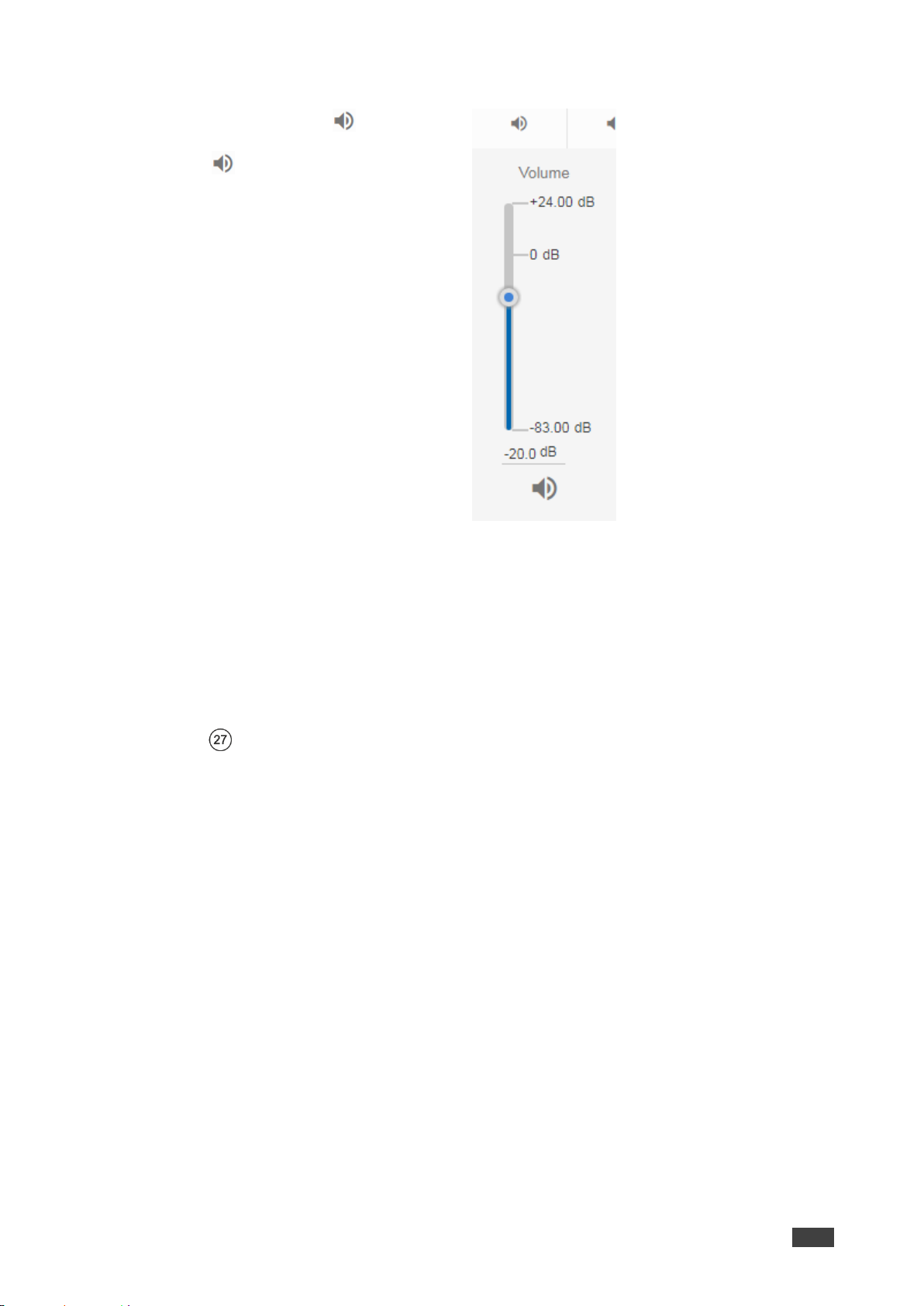
To set an audio output:
1. Click the audio icon ( ).
2. Use the slider to set the audio volume,
or click the below to mute the audio output.
Figure 78: Audio Settings
Setting RS-232 and Step-in Routing
You can set HDBT ports to either RS-232 data tunneling or Step-in modes via the RS-232
Routing Matrix page.
Setting and Routing the RS-232 Ports
RS-232 commands can be routed between HDBT inputs, HDBT outputs and the RS-232
DATA port .
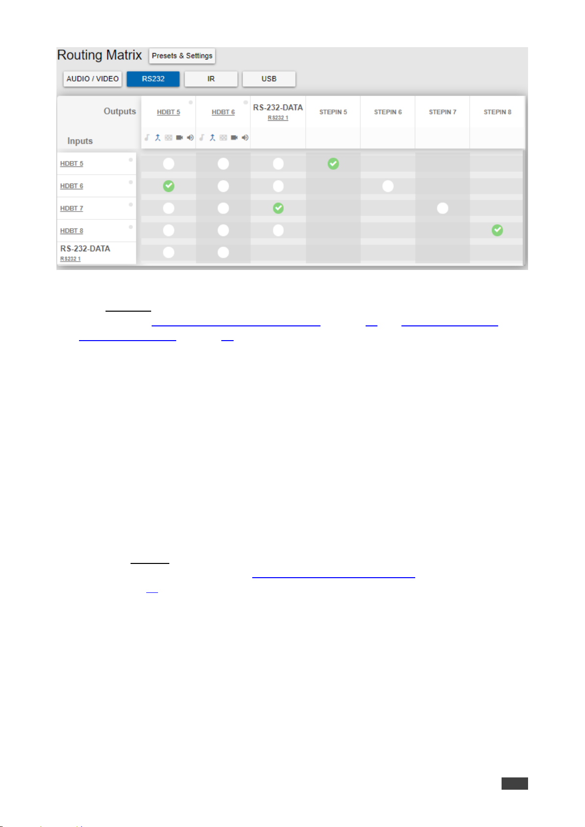
To route RS-232 signals:
1. Click Routing Settings page. The Routing Matrix page opens.
2. Click RS232. The RS-232 Routing page appears.
3. Click a white routing button within the matrix. For example:
▪ To route RS-232 signals between input HDBT 7 and RS-232 DATA, click the routing
button connecting them in the matrix.
▪ To tunnel RS-232 signals between HDBT 6 and HDBT 5, click the routing button
connecting them in the matrix.
Page 59
Kramer Electronics Ltd.
VS-88UT – Routing VS-88UT Ports
57
Figure 79: Routing Settings Page – RS-232 Routing
Click RS-232 1 on Inputs or Outputs to view the RS-232 routing status and change the port
label (see also Changing HDMI Input Port Settings on page 35 and Changing the HDBT
Output Port Settings on page 53).
Setting the Step-in Status on the HDBT Ports
You can activate the Step-in mode for each of the HDBT input ports on the VS-88UT so that
input signals from Step-in compatible switchers that are connected to the HDBT input ports on
the device can be routed to the outputs by pressing the STEP-IN button on the switchers.
To activate Step-in on the HDBT input ports:
1. Click Routing Settings page. The Routing Matrix page opens.
2. Click RS232. The RS-232 Routing page appears.
3. Click a white routing button within the matrix to activate Step-in.
▪ For example, to activate the HDBT 8 input, click the routing button connecting
STEPIN 8 and the HDBT8 in the matrix.
4. Click HDBT 8 to open the HDBT 8 settings page and select the outputs to which the
input signal will be routed (see Changing HDBT/HDMI and HDBT Port Settings
on page 41).
Page 60
Kramer Electronics Ltd.
VS-88UT – Routing VS-88UT Ports
58
Setting and Routing IR Ports
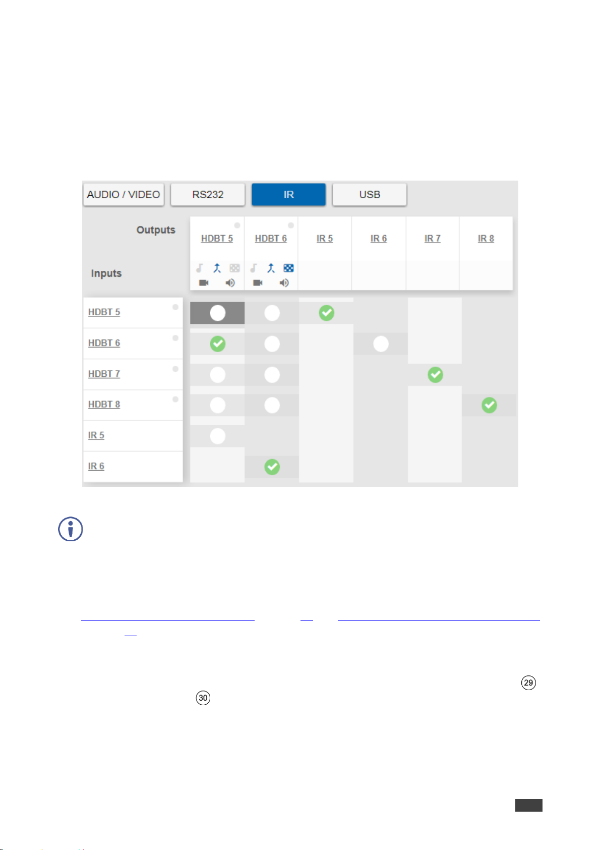
IR commands can be routed between HDBT inputs, HDBT outputs, IR inputs (5 to 6) and IR
outputs (5 to 8).
To route IR commands, click a white routing button within the matrix. For example, to route IR
commands between input HDBT 6 and HDBT 5, click the routing button connecting them in
the matrix:
Figure 80: Routing Settings Page – IR Routing
IR 5 to IR 8 (in the Outputs row) enable connecting an external IR sensor/emitter to send/receive IR
signals (5, 6, 7 and 8) via HDBT inputs 5, 6, 7 and 8 respectively.
IR 5 and IR 6 (in the Inputs column) enable connecting an external IR sensor/emitter to send/receive
IR signals (5 and 6) via HDBT outputs 5 and 6, respectively.
Click IR inputs or outputs to view the IR routing status and change the port label (see also
Changing HDMI Input Port Settings on page 35 and Changing the HDBT Output Port Settings
on page 53).
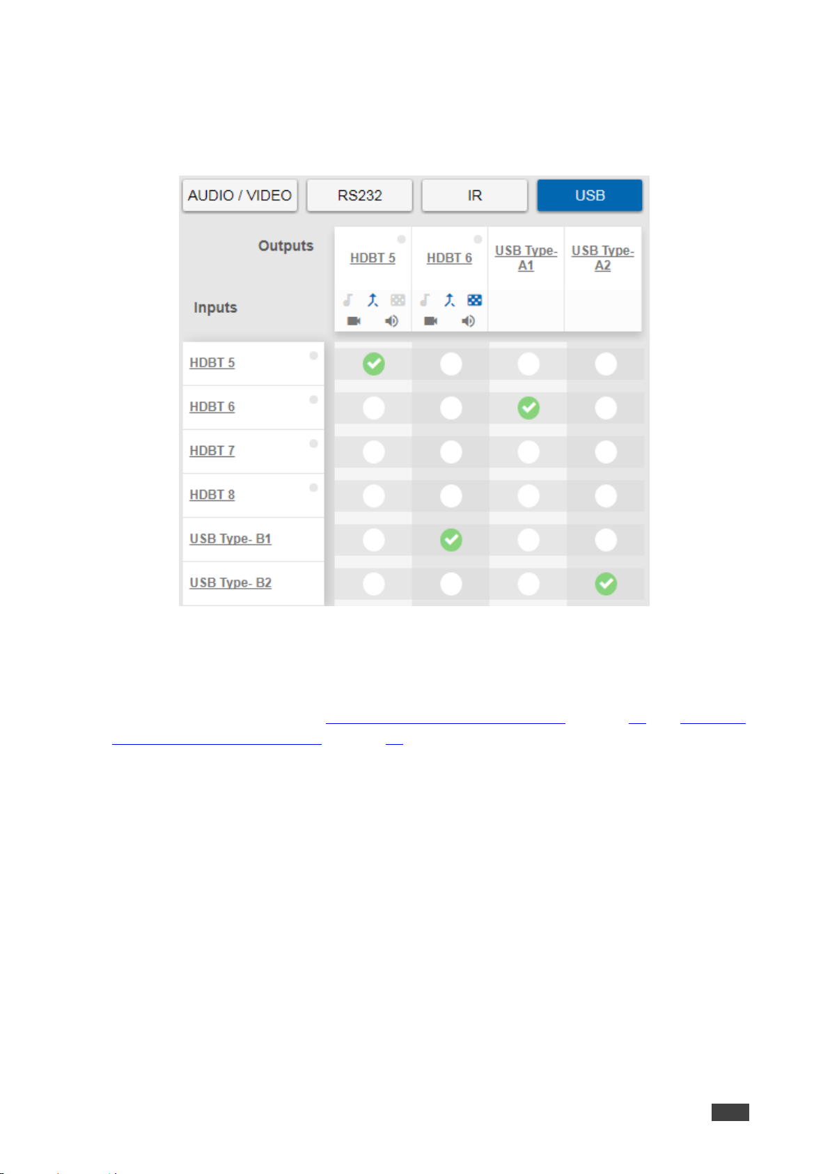
Setting and Routing the USB Ports
USB data can be routed between HDBT inputs, HDBT outputs and the USB Type-A hubs
and USB-Type-B ports .
Page 61
Kramer Electronics Ltd.
VS-88UT – Routing VS-88UT Ports
59
To route USB data:
• Click a white routing button within the matrix. For example, to route USB data between
input HDBT 6 and USB Type-A1 hub, click the routing button connecting them in the
matrix:
Figure 81: Routing Settings Page – USB Routing
Click an input, output or USB heading to view the USB routing status and other settings.
Click USB Type B on inputs or USB Type A on outputs to view the USB routing status and
change the port label (see also Changing HDMI Input Port Settings on page 35 and Changing
the HDBT Output Port Settings on page 53).
Page 62
Kramer Electronics Ltd.
VS-88UT – Managing EDID
60
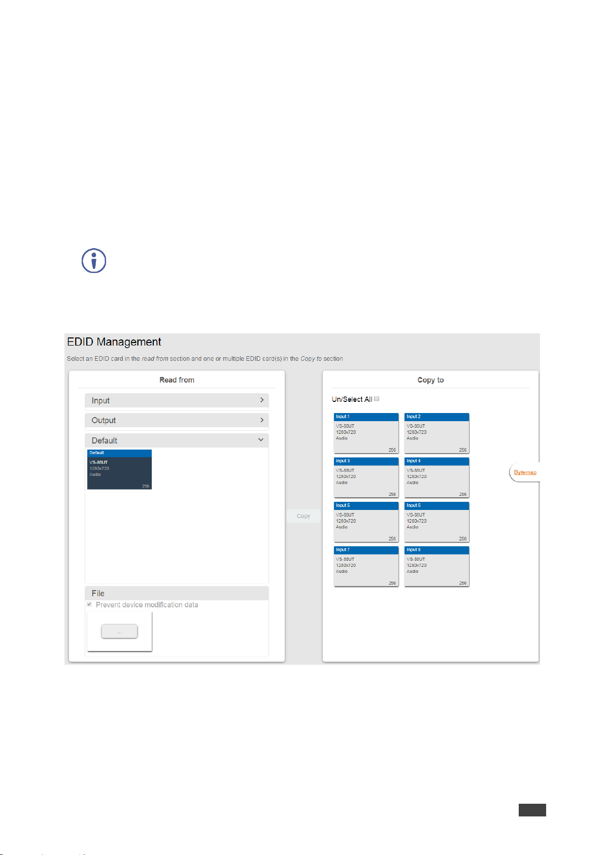
Managing EDID
The EDID page lets you read the EDID from:
• Any of the inputs.
• Any of the outputs.
• The default EDID.
You can also load a customized EDID file from your PC.
The selected EDID can be copied to the selected input/s.
View the currently selected EDID source Bytemap by clicking Bytemap on the right side.
To copy an EDID from an output to an input:
1. In the Navigation pane, click EDID. The EDID Management page appears.
Figure 82: EDID Management Page
Page 63
Kramer Electronics Ltd.
VS-88UT – Managing EDID
61
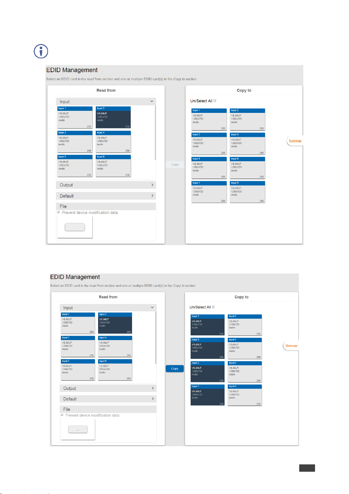
2. Select the EDID source (for example, one of the inputs).
If you are reading EDID from an output, make sure that that output is connected to an acceptor.
Figure 83: EDID Management Page – Select an EDID Input (Read From)
3. Select the input/s (or all the inputs) to which the EDID is copied.
Figure 84: EDID Management Page – Select the Inputs (Copy To)
Page 64
Kramer Electronics Ltd.
VS-88UT – Managing EDID
62
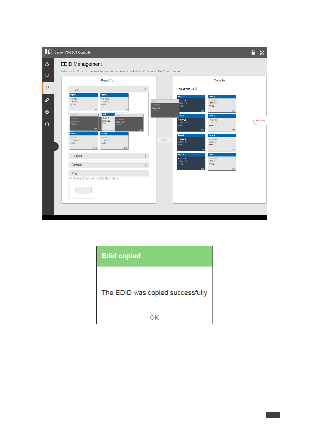
4. Click COPY.
The Input 2 EDID is copied to the selected inputs.
Figure 85: EDID Page – EDID Copied
The following message appears:
Figure 86: EDID Management Page – EDID Copy Success
5. Click OK.
To read the EDID from the default EDID:
1. In the Navigation pane, click EDID. The EDID Management page appears.
2. Click Default.
3. Select the input/s (or all the inputs) to which the default EDID is copied.
4. Click Copy and follow the instructions on-screen.
Page 65

Kramer Electronics Ltd.
VS-88UT – Managing EDID
63
To load a customized EDID file:
1. In the Navigation pane, click EDID. The EDID Management page appears.
2. In the File area click ….
3. Select the EDID file.
4. Select the input/s (or all the inputs) to which the EDID is copied.
5. Click Copy and follow the instructions on-screen.
Page 66
Kramer Electronics Ltd.
VS-88UT – Controlling Devices via the Controller
64
Controlling Devices via the Controller
You can control a large number of peripheral devices via the VS-88UT room controller section
(VS-88UT-RC) via Kramer K-Config 3. See Room Controller Functionality on page 6.
Use the Controller page to:
• Controlling Devices via the Controller on page 64.
• Activating Macros on page 72.
• Scheduling Macros on page 73.
• Setting the Date and Time on page 75.
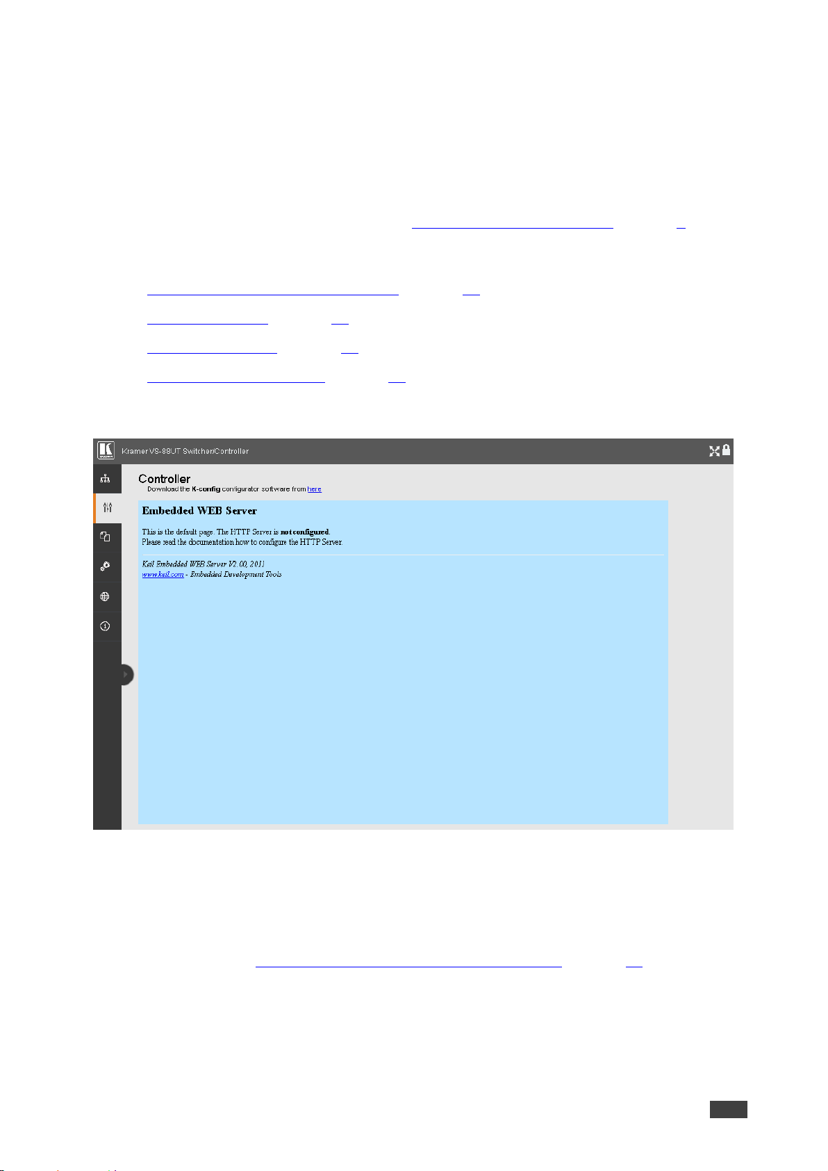
By default, the Controller page is empty, since a configuration is not yet synced to the device.
Figure 87: Controller Page – Default Page
To activate the Controller page:
• Click here to download K-Config 3.
• Create a room controller configuration via K-Config 3 and then sync the configuration to
the device (see Room Controller Configuration via K-Config 3 on page 65).
Page 67
Kramer Electronics Ltd.
VS-88UT – Controlling Devices via the Controller
65
Room Controller Configuration via K-Config 3
Download the latest version of K-Config 3 from our website at
www.kramerav.com/downloads/VS-88UT.
If you are new to K-Config 3, go to www.kramerav.com/downloads/VS-88UT to download the
K-Config 3 user manual.
In order to access K-Config 3 via the Controller page, connect it to the network via TCP
connection.
To create the room controller configuration:
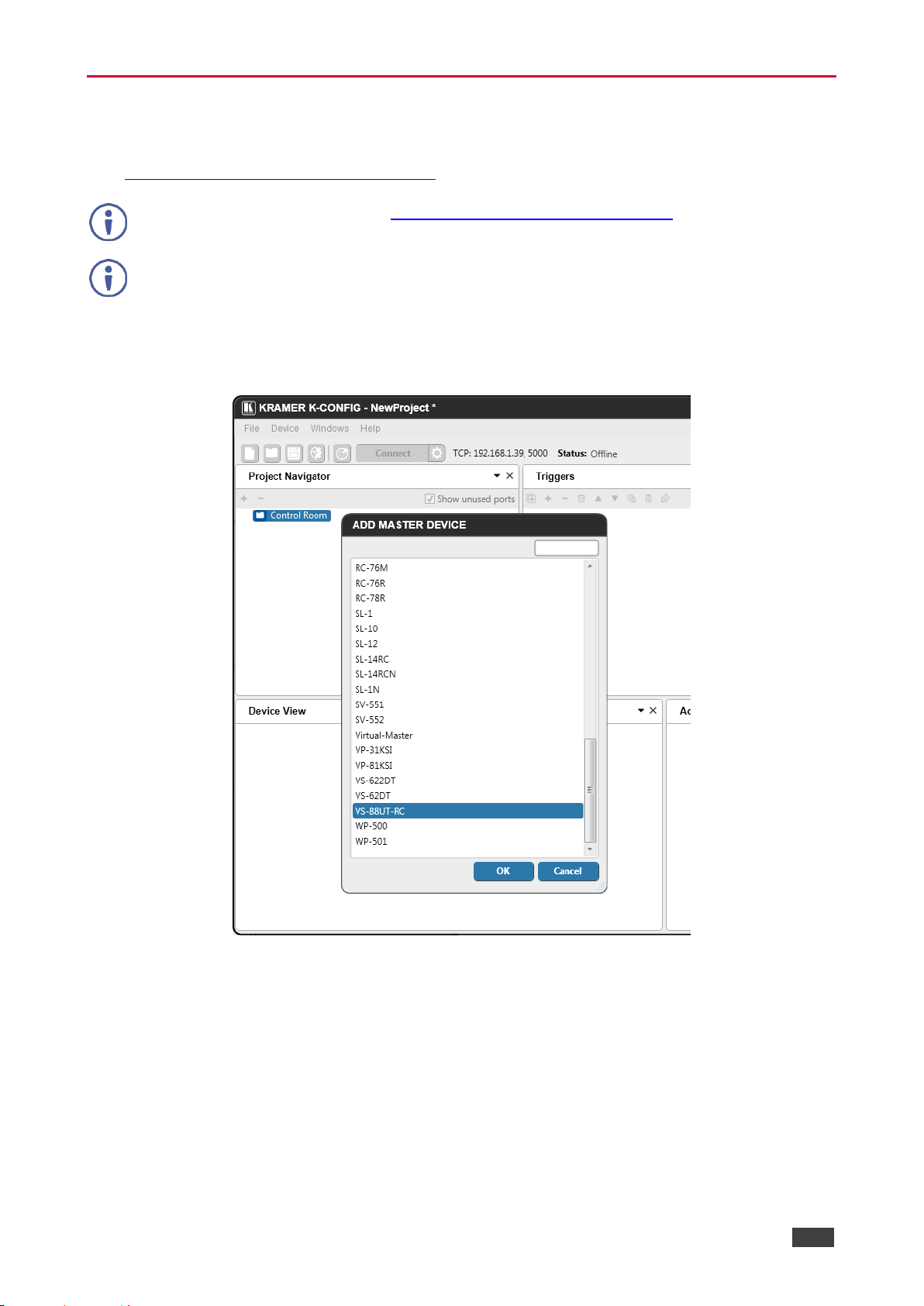
1. In K-CONFIG, select VS-88UT-RC as the master device.
Figure 88: Controller Page – Select Master Device via K-CONFIG
2. Click OK.
VS-88UT-RC is added as the Master controller with all its physical ports and virtual
Ethernet ports.
3. Configure the ports and add peripheral devices, commands and macros as needed.
4. Save the project in K-CONFIG.
5. In the Windows menu, select Web Settings and make sure that Upload Web Access
Pages to Device is checked.
Page 68
Kramer Electronics Ltd.
VS-88UT – Controlling Devices via the Controller
66
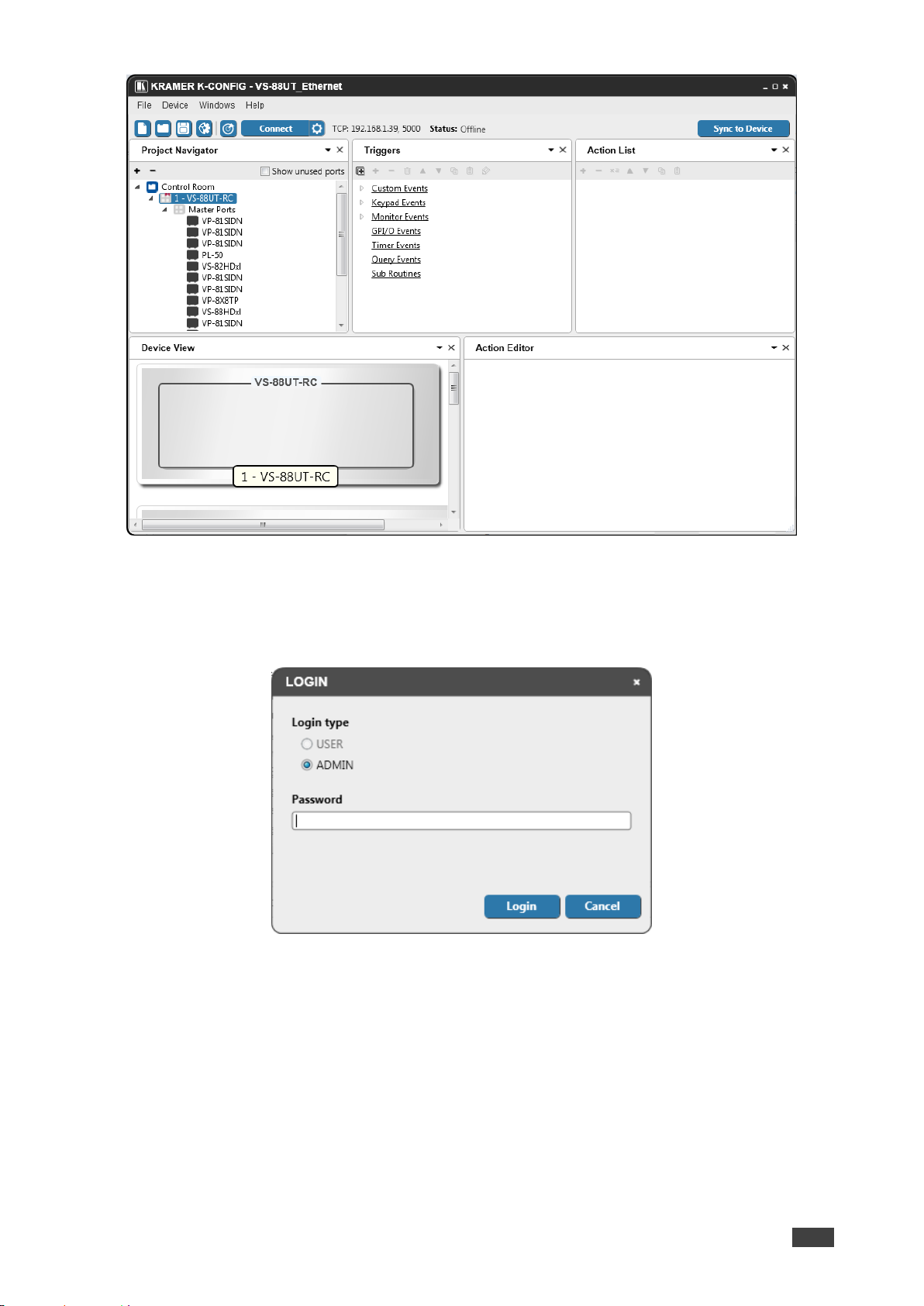
Figure 89: Controller Page – K-CONFIG Project
6. Connect the VS-88UT to your PC (via Ethernet).
7. Click Connect in K-CONFIG.
The following message appears:
Figure 90: Controller Page – Login
8. Type-in the VS-88UT webpage password for ADMIN (Admin, by-default).
9. Click Login.
K-CONFIG status displays Online.
10. Click Sync to Device.
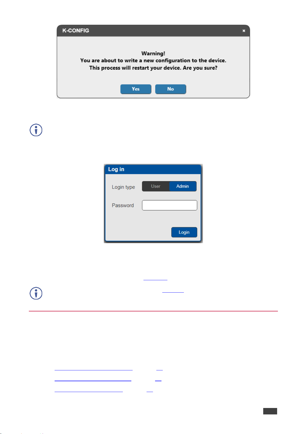
The following message appears:
Page 69
Kramer Electronics Ltd.
VS-88UT – Controlling Devices via the Controller
67
Figure 91: Controller Page – Writing to the Device
11. Click Yes.
This process may take a few minutes to complete.
12. Refresh the VS-88UT webpage.
13. In the Navigation pane, click Controller. The Log in window appears:
Figure 92: Controller Page – Log In Window
14. Set the Login type (Admin or User). For Admin, enter the password (Admin, by default).
15. Click Login.
The Controller page appears (see Figure 93).
If the Controller page does not load correctly (see Figure 87), you need to delete cached images and
files and the refresh the Controller page.
Controlling Devices
Devices that are connected to the VS-88UT room controller area are controlled via the
Controller page once the configuration is uploaded.
The device menu enables:
• Controlling a Peripheral Device on page 68.
• Controlling an Auxiliary Device on page 70.
• Controlling a Virtual Device on page 71.
Page 70
Kramer Electronics Ltd.
VS-88UT – Controlling Devices via the Controller
68
Controlling a Peripheral Device
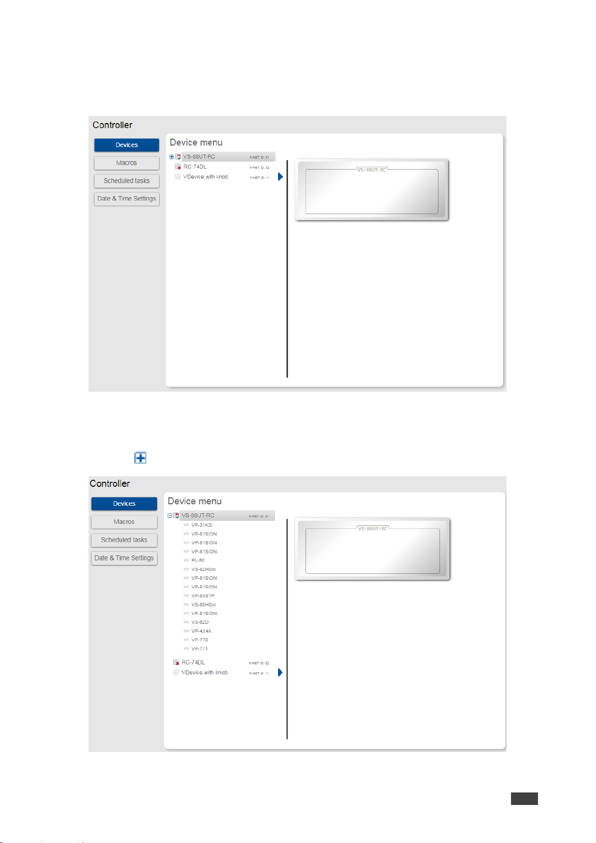
1. In the Controller page, click Devices.
The Device menu appears:
Figure 93: Controller Page – Device Menu
In this example, the Device menu list shows the room controller section (VS-88UT-RC),
an auxiliary device (Kramer RC-74DL) and a virtual device.
2. Click next to VS-88UT-RC to view the devices connected to the room controller:
Figure 94: Controller Page – Peripheral Device List
Page 71
Kramer Electronics Ltd.
VS-88UT – Controlling Devices via the Controller
69
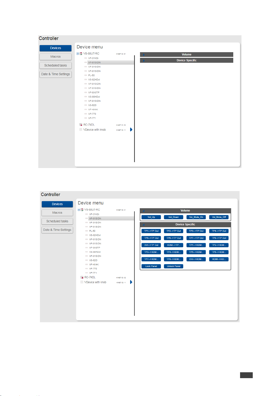
3. Click a device to control it, for example, VS-81SIDN:
Figure 95: Controller Page – Controlling a Peripheral Device
4. Expand the command types:
Figure 96: Controller Page –Peripheral Device Available Commands
The list of all the configured commands appears on the right-side of the page.
5. Click a command button.
The selected command is performed on the peripheral device.
Page 72
Kramer Electronics Ltd.
VS-88UT – Controlling Devices via the Controller
70
Controlling an Auxiliary Device
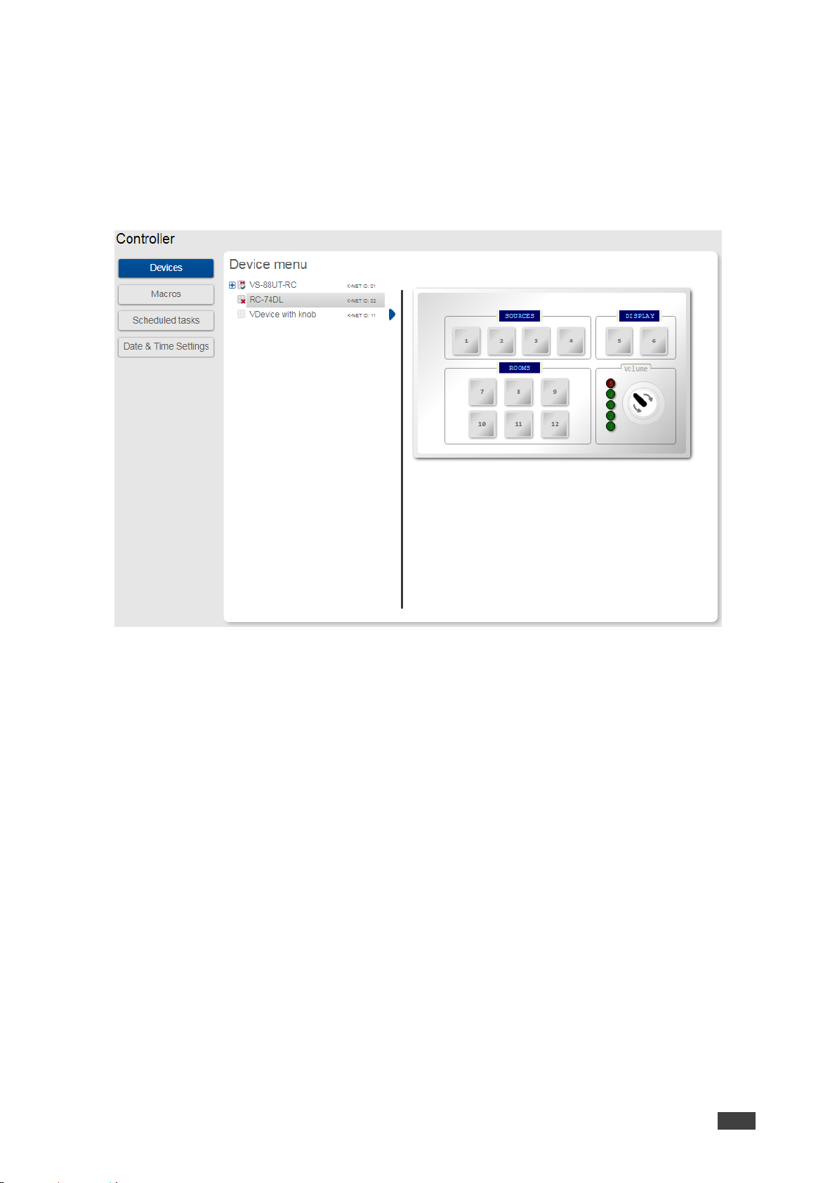
To control an auxiliary device:
1. In the Controller page, click Devices.
2. Click an Auxiliary device (RC-74DL).
The Device menu appears:
Figure 97: Controller Page – Controlling an Auxiliary Device
3. Click a room-controller device-button.
The action list (as defined by K-Config 3) is performed.
Page 73
Kramer Electronics Ltd.
VS-88UT – Controlling Devices via the Controller
71
Controlling a Virtual Device
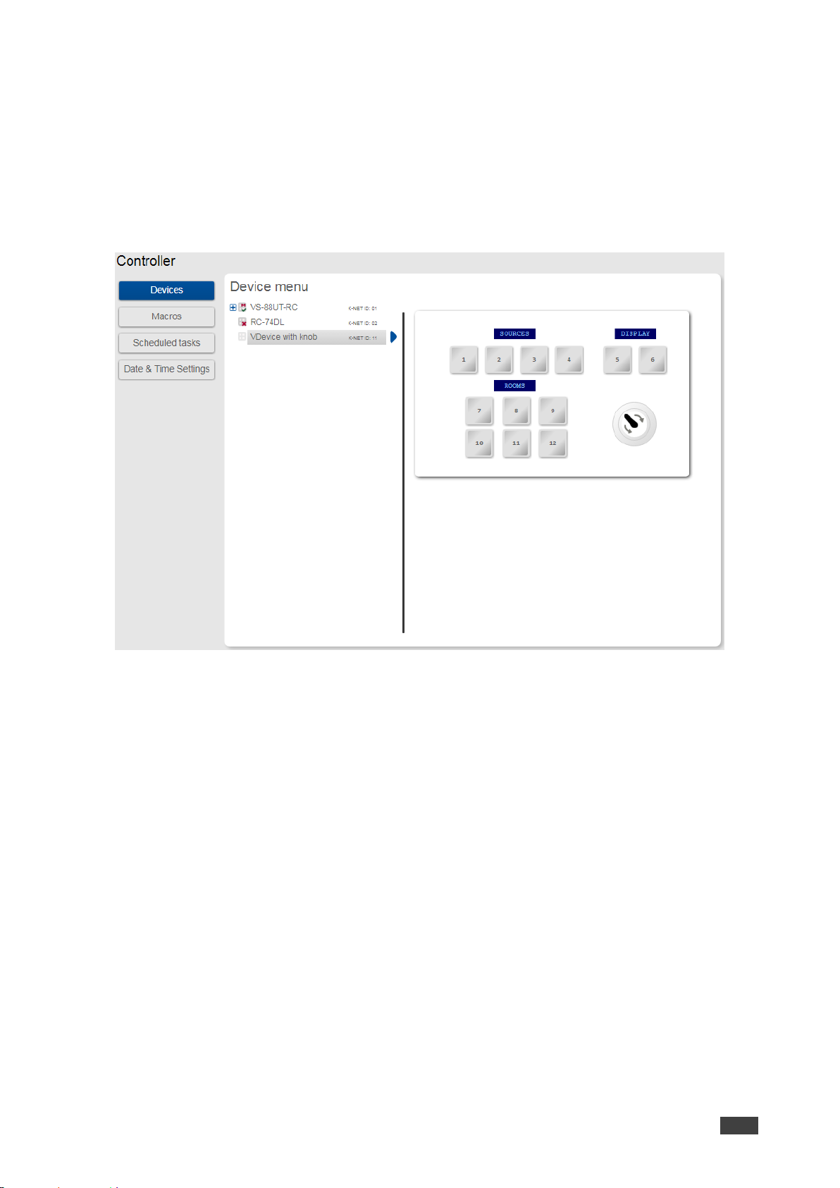
To control a virtual device:
1. In the Controller page, click Devices.
The Device menu appears:
2. Click a virtual device on the list (for example, VDevice with Knob).
The virtual device appears:
Figure 98: Controller Page – Controlling a Virtual Device
3. Click a room-controller device-button.
The action list (as defined by K-Config 3) is performed.
4. If desired, click the blue arrow next to the virtual device for a full-page view (enables a
clearer view when the virtual device includes several sets of device controllers).
Page 74
Kramer Electronics Ltd.
VS-88UT – Controlling Devices via the Controller
72
Activating Macros
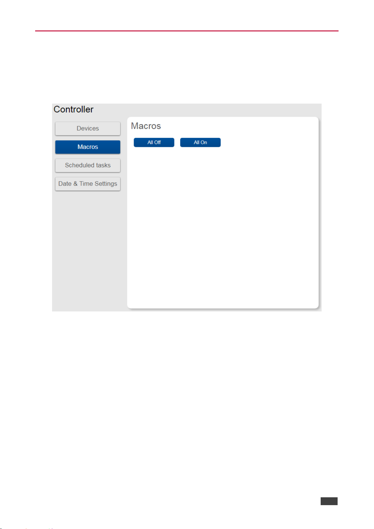
Macros include All Off and All On buttons (configured in K-CONFIG) to easily activate or
deactivate the controlled room with the press of a button.
1. In the Controller page click Macros.
The Macros window appears:
Figure 99: Controller Page – Macros Window
2. Click All On or All Off as required.
Page 75
Kramer Electronics Ltd.
VS-88UT – Controlling Devices via the Controller
73
Scheduling Macros
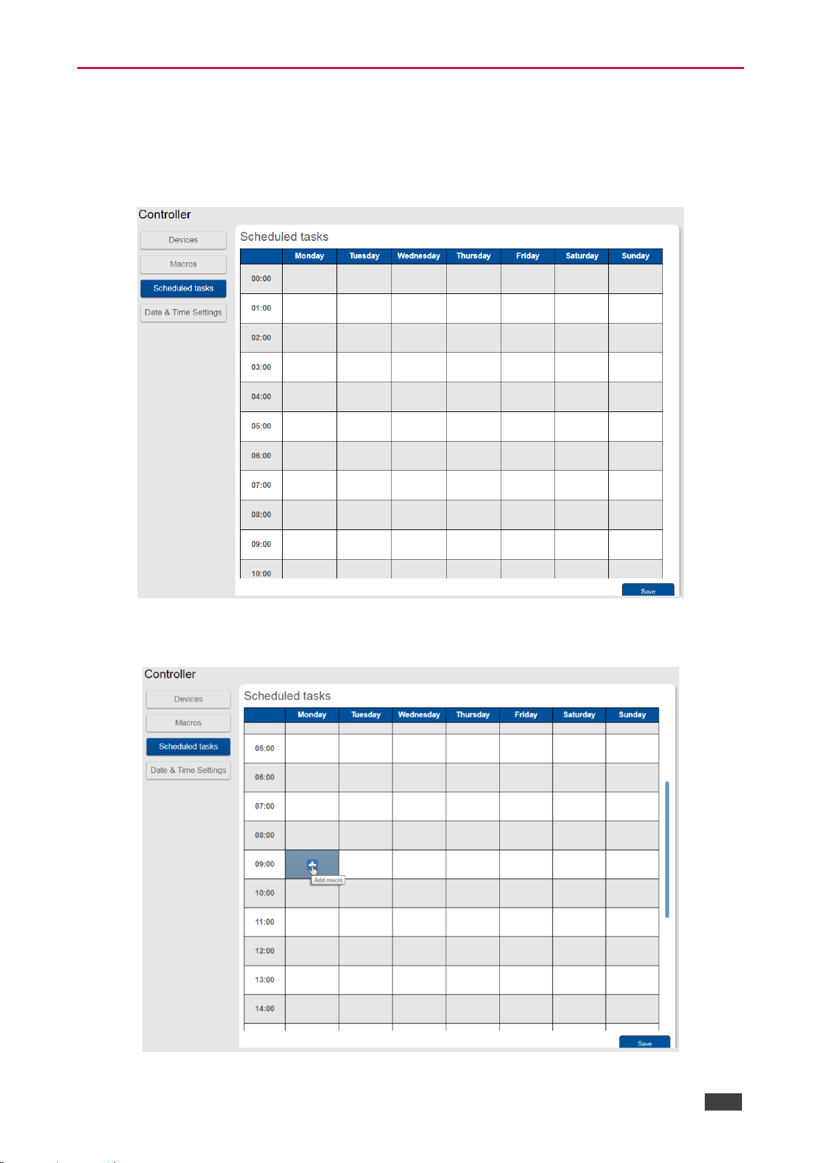
Scheduled tasks lets you schedule All on/All Off macros throughout the week.
1. In the Controller page click Scheduled Tasks.
The Scheduled Tasks window appears:
Figure 100: Controller Page – Scheduled Tasks
2. Hover over a day and time
Figure 101: Controller Page – Selecting a Day and Time
Page 76
Kramer Electronics Ltd.
VS-88UT – Controlling Devices via the Controller
74
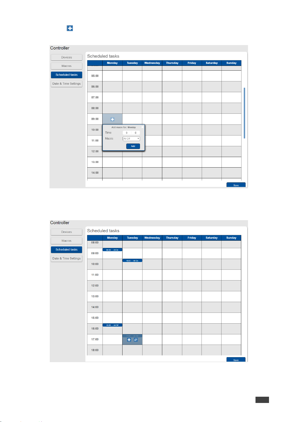
3. Click .
The Add Macro window appears:
Figure 102: Controller Page – Adding a Scheduled Task
4. Select a Macro (All On or All Off), set the exact activation time and click Add.
The scheduled macro appears in the table:
Figure 103: Controller Page – Scheduled Task Added
Page 77
Kramer Electronics Ltd.
VS-88UT – Controlling Devices via the Controller
75
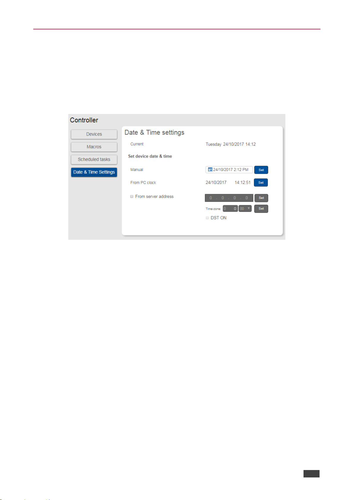
Setting the Date and Time
Set the date and time in one of the following methods:
• Manually
• From a PC clock
• From a server address by clicking the IP address of the clock source, the time zone and
checking DST if you are on Daylight Saving Time.
Figure 104: Controller Page – Date and Time Settings
Page 78
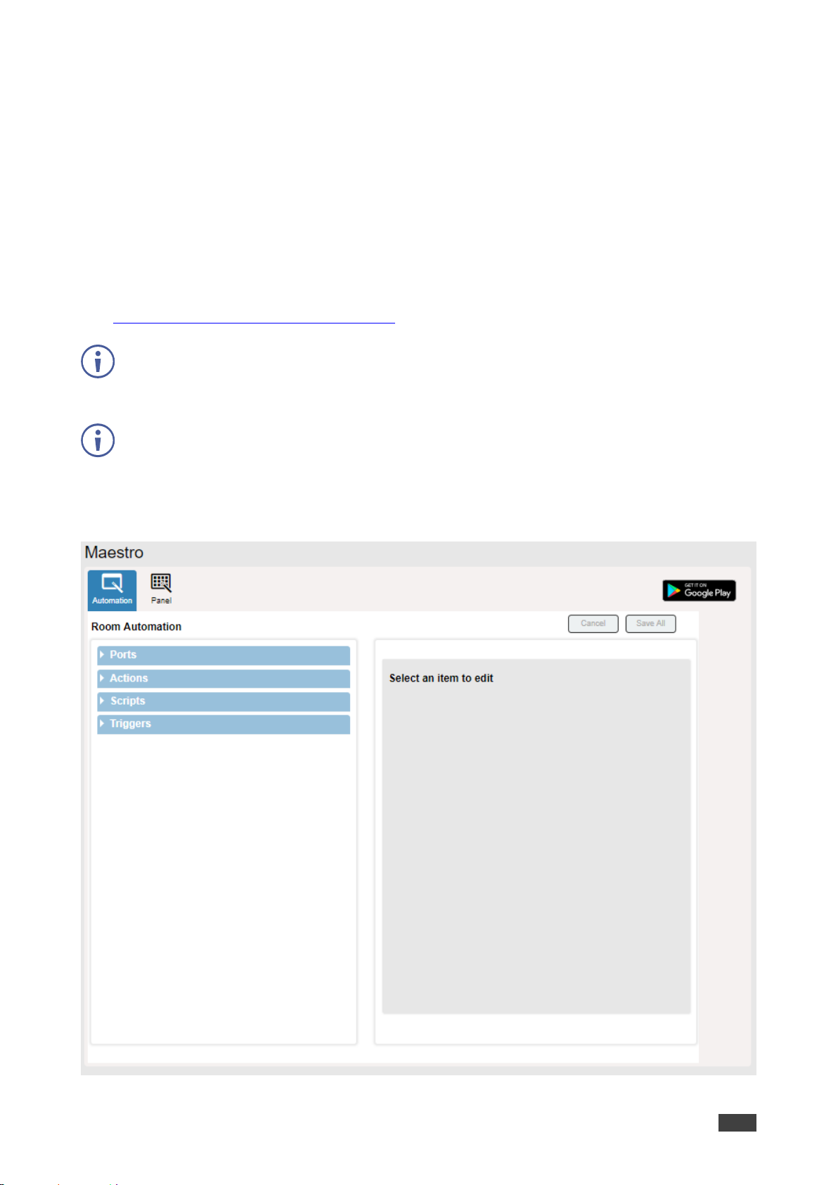
Kramer Electronics Ltd.
VS-88UT – Configuring Device Automation
76
Configuring Device Automation
Use the Automation page to access Kramer Maestro V1.5 room automation. Maestro is a
powerful tool that enables you to configure single-trigger room element automation scenarios
without the need for complicated programming. To use room automation, you need to define
triggers that, upon an event, will execute scripts which include a sequence of actions
(commands, which can appear in different scenarios) that will be carried out via any defined
ports.
Download the Kramer Maestro User Manual from the Kramer web site at
www.kramerav.com/downloads/VS-88UT to learn how to use Kramer Maestro.
Note that all the ports, actions and triggers that are relevant to VS-88UT are included in the
Kramer Maestro, as well as ports, actions and triggers that are relevant to other Kramer
devices.
The Panel tab in the Automation page is currently unavailable.
To access Kramer Maestro:
1. In the Navigation pane, click Automation. The Maestro page appears.
Figure 105: Automation Page
Page 79

Kramer Electronics Ltd.
VS-88UT – Configuring Device Automation
77
2. Configure the ports, actions, scripts and triggers as described in the Kramer Maestro
User Manual.
Once the triggers are defined the trigger activates the scripts configured in the automation
page. For example, when using the Scheduling trigger, you can activate a series of actions
following a preset schedule.
Page 80
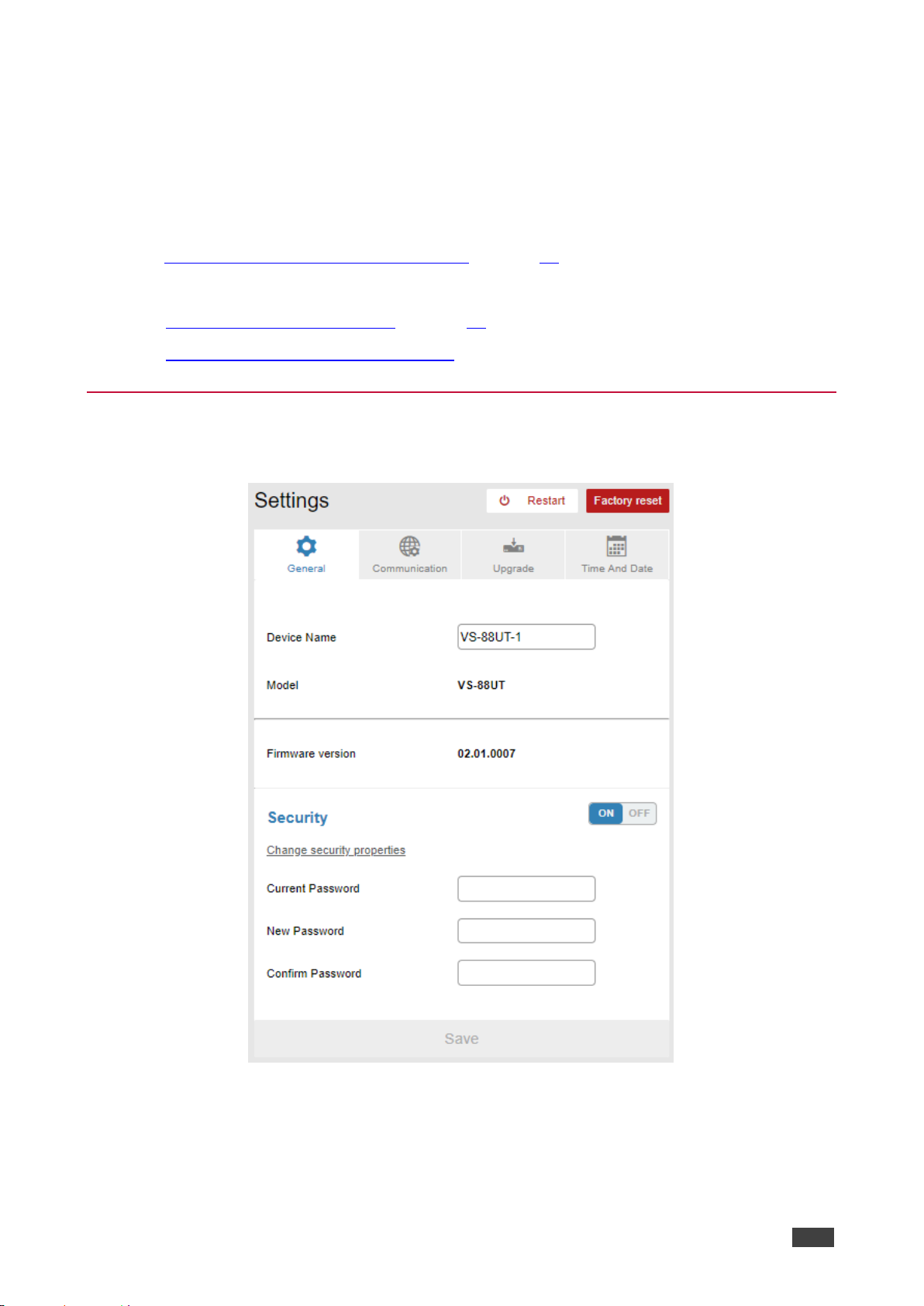
Kramer Electronics Ltd.
VS-88UT – Changing the Device Settings
78
Changing the Device Settings
The Settings Web page shows the device details such as name and firmware version and
also enables performing the following functions:
• Clicking Restart to restart the device.
• Resetting to Factory Default Parameters on page 78.
• Changing the Device Name by typing the new name and saving it.
• Performing Firmware Upgrade on page 83.
• Setting the Date and Time on page 84.
Resetting to Factory Default Parameters
1. In the Navigation pane, click Settings. The General tab in the Settings page appears:
Figure 106: Settings Page
Page 81
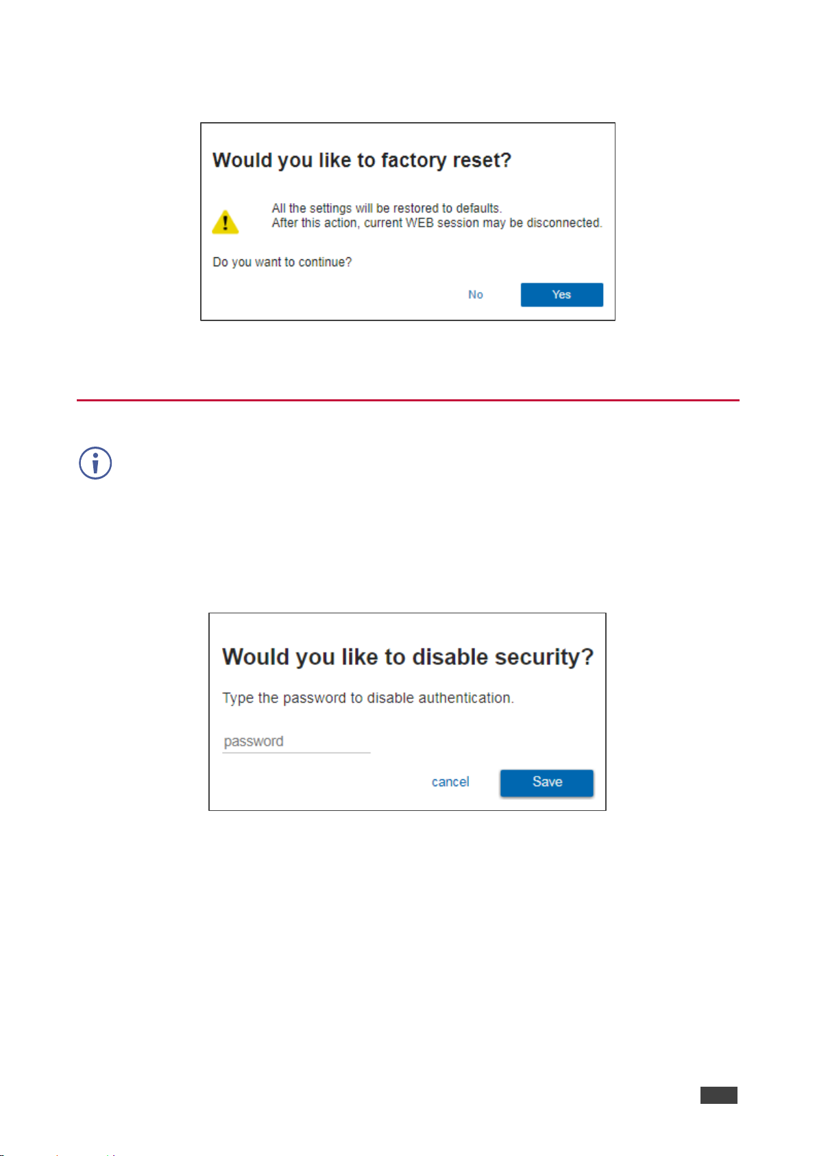
Kramer Electronics Ltd.
VS-88UT – Changing the Device Settings
79
2. Click Factory reset.
The following message appears:
Figure 107: Settings Page – Factory Reset Message
3. Click Yes and follow the online instructions.
Setting Authentication
By default, the Web pages are secured (username and password are both: Admin).
To access web pages without using the password:
1. In the Navigation pane, click Settings. The General tab in the Settings page appears:
2. Slide the Security switch to OFF.
The following message appears:
Figure 108: Password Settings Page – Disabling Authentication
Page 82
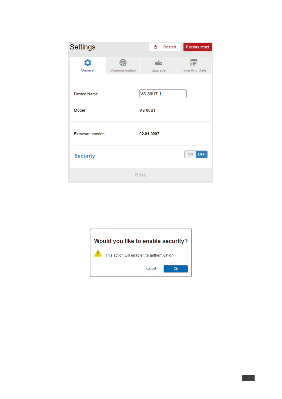
Kramer Electronics Ltd.
VS-88UT – Changing the Device Settings
80
3. Type the password and click Save.
The device settings page no longer shows the authentication details:
Figure 109: Password Settings Page –Security Deactivated
To access Web pages using the password:
1. In the Navigation pane, click Settings. The General tab in the Settings page appears:
2. Slide the security switch to ON. The following message appears:
Figure 110: Password Settings Page – Activating Security
Page 83
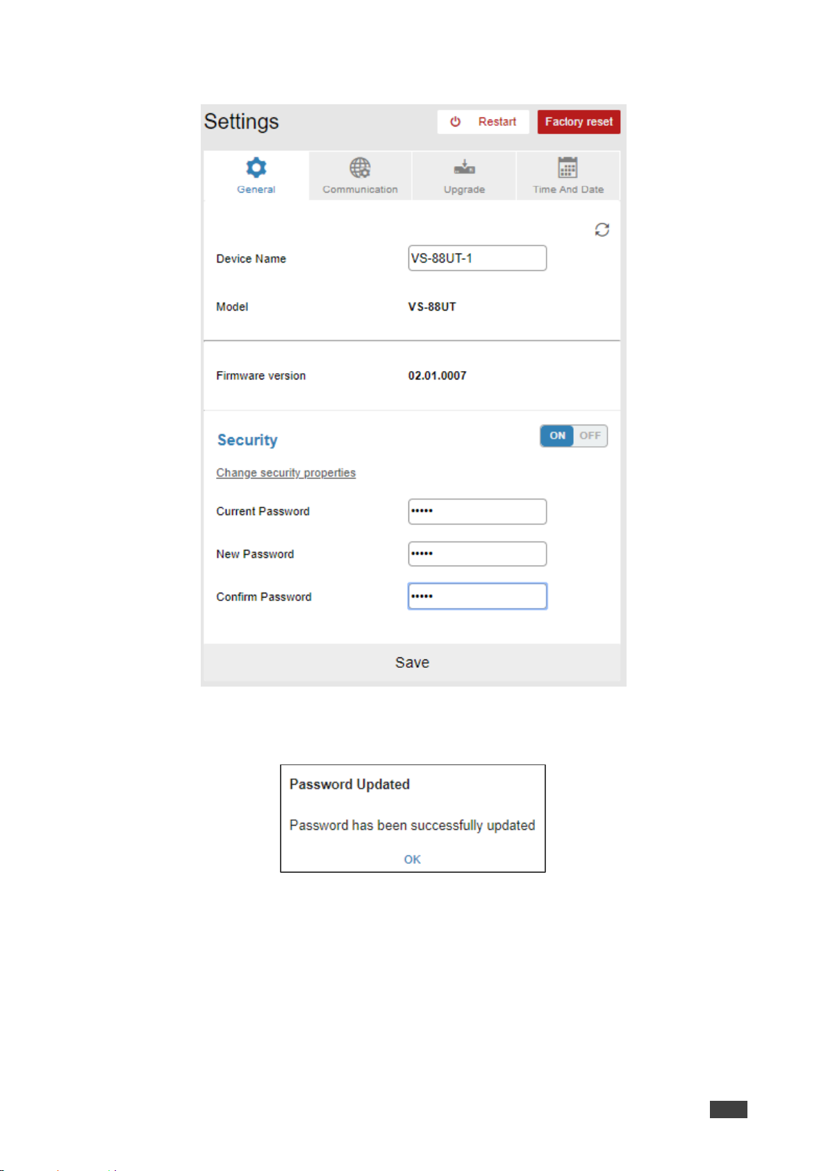
Kramer Electronics Ltd.
VS-88UT – Changing the Device Settings
81
3. Click Ok and add the password details.
Figure 111: Settings Page – Security Activation Message
4. Click Save. The following message appears:
Figure 112: Settings Page – Password Updated
5. Click OK.
Page 84
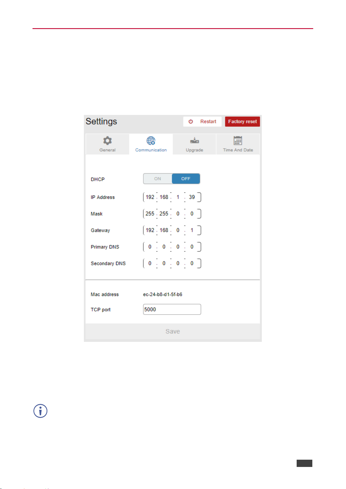
Kramer Electronics Ltd.
VS-88UT – Changing the Device Settings
82
Changing the Ethernet Settings
The Communication tab shows the device details, such as IP Address, Mask, MAC address
and so on, and enables changing them.
To change the Ethernet settings:
1. In the Navigation pane, click Settings. The General tab in the Settings page appears.
2. Select the Communication tab:
Figure 113: Settings Page – Communication Tab
3. If DHCP is set to OFF, change any of the parameters (IP Address, Netmask and/or
Gateway).
4. If required, change the TCP port number.
5. Click Save.
After changing the IP address, reload the Web page with the new IP address.
If DHCP is checked, reload the Web page with the new IP address (see below).
Page 85
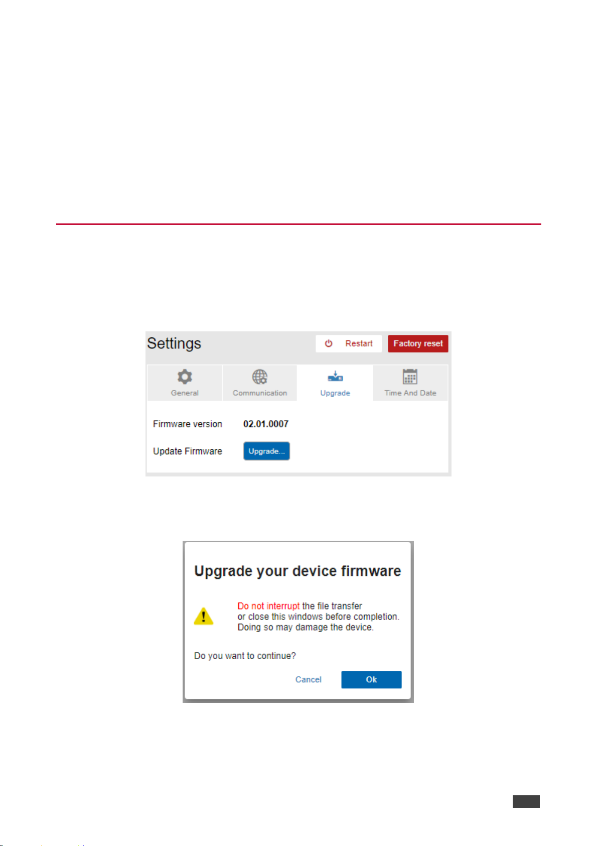
Kramer Electronics Ltd.
VS-88UT – Changing the Device Settings
83
To set parameters when DHCP is set to ON:
1. In the Navigation pane, click Settings. The General tab in the Settings page appears.
2. Select the Communication tab.
3. Take note of the Device Name (you will need it later).
4. Set DHCP to ON.
5. Click Save.
6. Type the device name in the address bar of your browser to reload the page.
You can read the new IP address from the Network Settings page.
Performing Firmware Upgrade
To perform firmware upgrade:
1. In the Navigation pane, click Settings. The General tab in the Settings page appears.
2. Select the Upgrade tab.
Figure 114: [Figure Caption]
3. Click Upgrade and select the new firmware file.
The following message appears:
Figure 115: Device Settings Page – Firmware Upgrade Message
Page 86
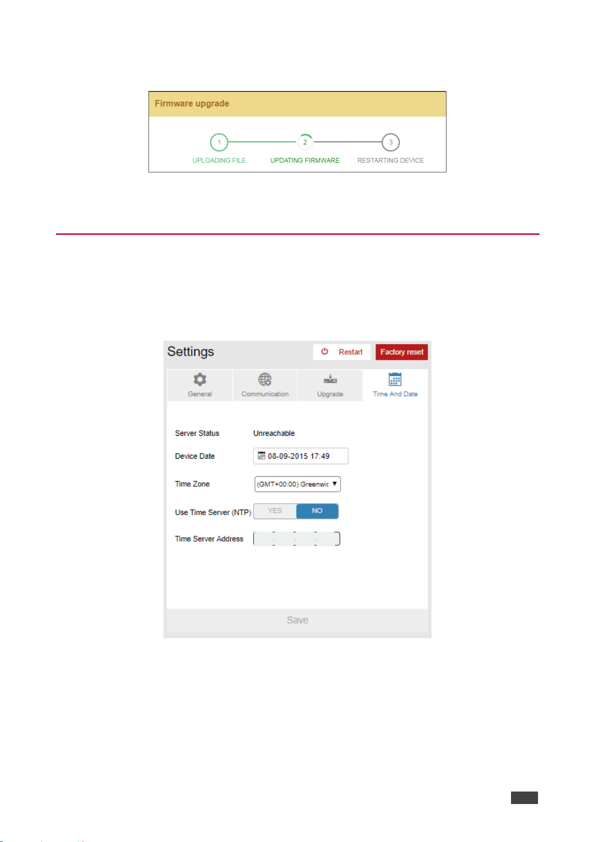
Kramer Electronics Ltd.
VS-88UT – Changing the Device Settings
84
4. Click OK.
Wait for completion of the upgrade process:
Figure 116: Device Settings Page – Firmware Upgrade Process
5. Wait for the device to restart.
Setting the Date and Time
To set the time and date:
1. In the Navigation pane, click Settings. The General tab in the Settings page appears.
2. Select the Time and Date tab.
Figure 117: Time and Date
3. Set the following:
▪ Device Date
▪ Time Zone
4. If required, use time server (disables setting device date) and set the time server
address.
5. Click Save.
Page 87
Kramer Electronics Ltd.
VS-88UT – Viewing the About Page
85
Viewing the About Page
The VS-88UT About page lets you view the Web page version and Kramer Electronics Ltd
details.
Figure 118: About Page
Page 88
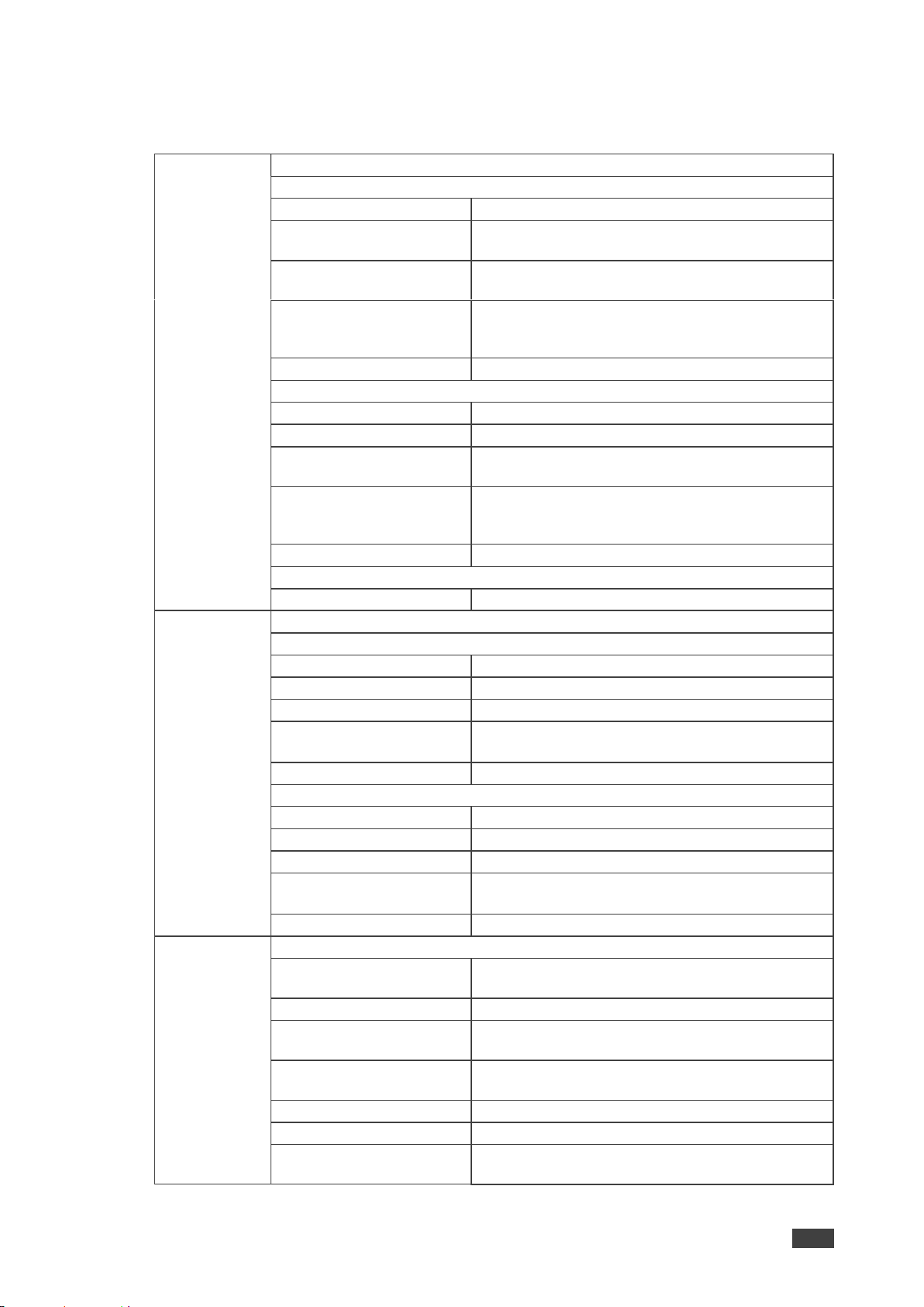
Kramer Electronics Ltd.
VS-88UT – Technical Specifications
86
Technical Specifications
Inputs
Matrix
VS-88UT
4 HDMI
On female HDMI connectors
4 HDBT/4 HDMI
(Selectable)
On RJ-45/female HDMI connectors
4 Unbalanced Stereo
Audio
On 3.5mm mini jacks
4 Balanced Stereo
Audio/8 Balanced Mic
(Selectable)
On 5-pin/3-pin terminal block connectors
4 IR
On 3.5mm mini jacks for IR tunneling via HDBT
VS-84UT
6 HDMI
On female HDMI connectors
2 HDBT
On RJ-45 connectors
4 Unbalanced Stereo
Audio
On 3.5mm mini jacks
4 Balanced Stereo
Audio/8 Balanced Mic
(Selectable)
On 5-pin/3-pin terminal block connectors
2 IR
On 3.5mm mini jacks for IR tunneling via HDBT
Controller
2 IR
On 3.5mm mini jacks
Outputs
Matrix
VS-88UT
6 HDMI
On female HDMI connectors
2 HDBT
On RJ-45 female connectors
2 Balanced Stereo Audio
On 5-pin terminal block connectors
1 Stereo Speaker Output,
2x50W into 4
On a 4-pin terminal block connector
2 IR
On 3.5mm mini jacks for IR tunneling via HDBT
VS-84UT
2 HDMI
On female HDMI connectors
2 HDBT
On RJ-45 female connectors
2 Balanced Stereo Audio
On 5-pin terminal block connectors
1 Stereo Speaker Output,
2x50W into 4
On a 4-pin terminal block connector
2 IR
On 3.5mm mini jacks for IR tunneling via HDBT
Ports
Matrix
1 RS-232
On a 3-pin terminal block for serial tunneling via
HDBT
1 RS-232
On a 3-pin terminal block for device control
4 USB (2+2)
On female USB-A connectors for USB link
extension
2 USB
On female USB-B connectors for USB link
extension
ETH Control
On a RJ-45 female connector
ETH Data 1G
On an RJ-45 female connector
1 100BaseT Ethernet
On an RJ-45 female connector for device control
and LAN extension
Page 89

Kramer Electronics Ltd.
VS-88UT – Technical Specifications
87
Ports
Controller
1 K-NET 5mm Mini-jack
(For Learning).
On a 4-pin terminal block connector
1 RS-485
On a 3-pin terminal block connector
4 RS-232
On 3-pin terminal block connectors
8 Relays
On 2-pin terminal block connectors (36V AC or
DC, 2A, 60VAC maximum on non-inductive load)
4 GPI/O
On 2-pin terminal blocks
1 Mini USB
Connector for programming services
Extension
Reach
4K @60Hz (4:2:0)
Up to 100m (330ft)
Full HD (1080p @60Hz
36bpp)
Up to 130m (430ft)
HDBaseT Ultra Mode and
Full HD (1080p @60Hz
24bpp)
Up to 180m (590ft)
Compliance
HDBaseT 2.0
Controls
ON
LED indicator
STATUS
LED indicator
Controller
K-NET Termination
Switch (down for termination)
RS-485 Terminator
Switch (down for termination
PROG
Switch (down for programming)
Video
Max Bandwidth
10.2Gbps (3.4Gbps per graphic channel)
Max Resolution
4K @60Hz (4:2:0) 24bpp resolution
Compliance
HDMI and HDCP 1.4
Analog Audio
Max Level
1 Vrms
THD + NOISE
0.03% @1kHz at nominal level
Extended
USB
Host Compliance
1.1 and 2.0
Max Extended Line Rate
Bandwidth
127Mbps (out of max 480 USB)
Max Devices
7
Max Hubs
2
Max Ports per Hub
8
Extended
Ethernet
Max Transmission
Bandwidth
100Mbps
Extended
RS-232
Baud Rate
300 to 57600
Control
RS-232
Baud Rate
115200
Supported PC
Web
Browsers
Windows 7 and Higher
Internet Explorer (32/64 bit) version 10
Firefox version 30
Chrome version 35
MAC
Chrome version 35
Firefox version 30
Safari version 7
Optimal Resolution
1920x1080
Minimal Resolution
1024 x 768
Power
Consumption
VS-88UT: 250VA
VS-84UT: 200VA
Source
100-240V AC, 50/60Hz
Environmental
Conditions
Operating Temperature
0° to +40°C (32° to 104°F)
Storage Temperature
-40° to +70°C (-40° to 158°F)
Humidity
10% to 90%, RHL non-condensing
Page 90
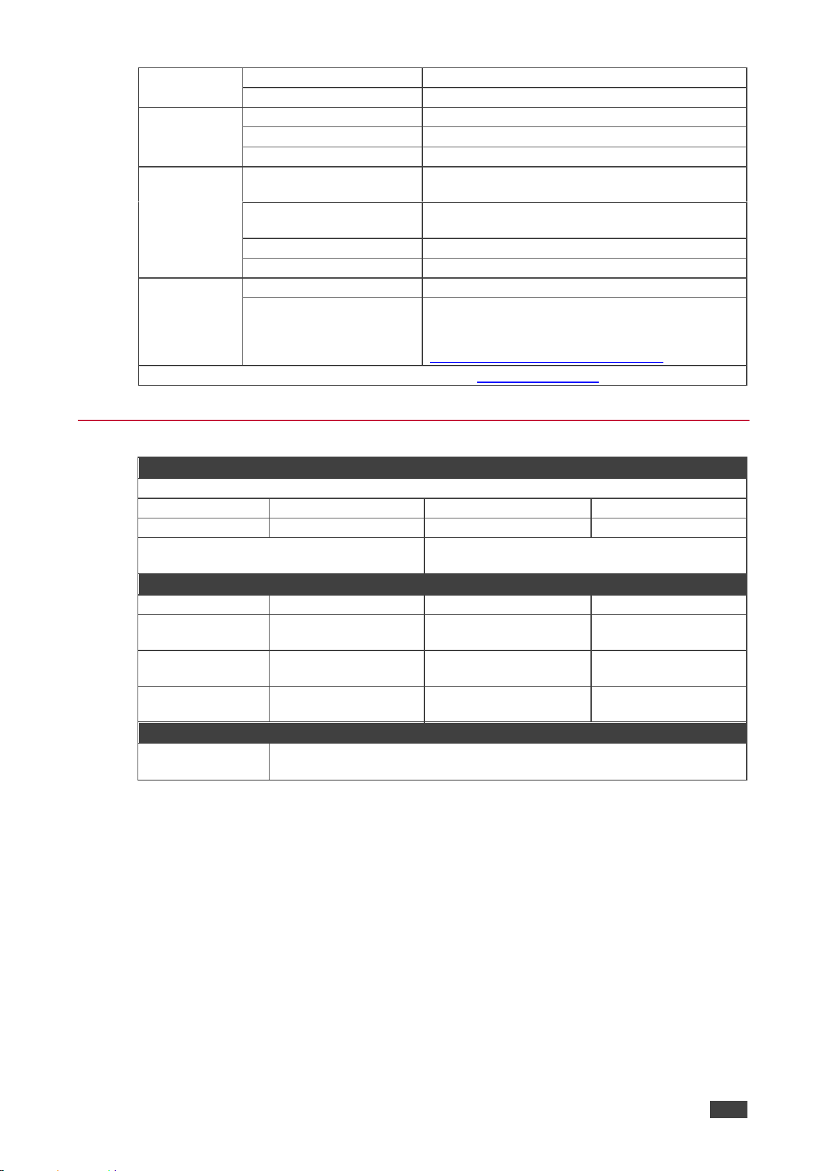
Kramer Electronics Ltd.
VS-88UT – Technical Specifications
88
Regulatory
Compliance
Safety
CE, UL
Environmental
RoHs, WEEE
Enclosure
Size
19", 19", 2U, rack mountable
Type
Aluminum
Cooling
Fan ventilation
General
Net Dimensions (W, D, H)
43.7cm x 30.6cm x 8.8cm
(17.2" x 12" x 3.5")
Shipping Dimensions (W,
D, H)
52.6cm x 47.5cm x 18.4cm
(20.7" x 18.7" x 7.2")
Net Weight
3.9kg (8.6lbs)
Shipping Weight
5.4kg (11.9lbs) approx.
Accessories
Included
Power cord
Optional
For optimum range and performance use the
recommended USB, Ethernet, serial and IR
Kramer cables available at
www.kramerav.com/product/VS-88UT
Specifications are subject to change without notice at www.kramerav.com
Default Communication Parameters
RS-232
Protocol 3000
Baud Rate:
115200
Stop Bits:
1
Data Bits:
8
Parity:
None
Example (Set the volume on analog audio
input 5 to 10dB):
#X-AUD-LVL
IN.ANALOG_AUDIO.5.AUDIO.1,10
TCP/IP Parameters
IP Address:
192.168.1.39
UDP Port #:
50000
Subnet mask:
255.255.000.000
Maximum UDP
Connections:
Unlimited
Default gateway:
192.168.0.1
Maximum TCP
Connections:
70 (Web client not
connected)
TCP Port #:
5000
Maximum TCP
Connections:
10 (Web client
connected)
Full Factory Reset
Protocol 3000
Use “#FACTORY” command and use “#RESET” to restore the factory default
values.
Page 91
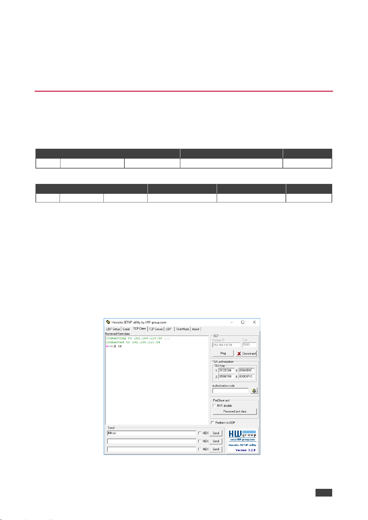
Kramer Electronics Ltd.
VS-88UT – Protocol 3000
89
Protocol 3000
Kramer devices can be operated using Kramer Protocol 3000 commands sent via serial or
Ethernet ports.
Understanding Protocol 3000
Protocol 3000 commands are a sequence of ASCII letters, structured according to the
following.
• Command format:
Prefix
Command Name
Constant (Space)
Parameter(s)
Suffix
#
Command
Parameter
<CR>
• Feedback format:
Prefix
Device ID
Constant
Command Name
Parameter(s)
Suffix
~
nn @ Command
Parameter
<CR><LF>
• Command parameters – Multiple parameters must be separated by a comma (,). In
addition, multiple parameters can be grouped as a single parameter using brackets ([
and ]).
• Command chain separator character – Multiple commands can be chained in the
same string. Each command is delimited by a pipe character (|).
• Parameters attributes – Parameters may contain multiple attributes. Attributes are
indicated with pointy brackets (<…>) and must be separated by a period (.).
The command framing varies according to how you interface with the VS-88UT. The following
figure displays how the # command is framed using terminal communication software (such
as Hercules):
Page 92
Kramer Electronics Ltd.
VS-88UT – Protocol 3000
90
Protocol 3000 Commands
This table describes the VS-88UT protocol commands. Note that this protocol is the same for
VS-84UT except for the number of inputs and outputs. For example, in the Display command
output can be set from 1 to 8 for VS-88UT and from 1 to 4 for VS-84UT.
Function
Description
Syntax
Parameters/Attributes
Example
#
Protocol handshaking.
Validates the Protocol
3000 connection and gets
the machine number.
Step-in master products
use this command to
identify the availability of
a device.
COMMAND
#<CR>
FEEDBACK
~nn@OK<CR><LF>
#<CR>
AV-SWTIMEOUT
Set auto switching
timeout.
COMMAND
#AV-SW-TIMEOUTaction,time_out<CR>
FEEDBACK
~nn@AV-SW-TIMEOUTaction,time_out<CR><LF>
action –
0 – Video signal lost.
1 – New video signal detected.
4 – Disable 5V on video output if no
input signal detected
5 – Video cable unplugged.
7 – Video signal lost for signal
routed as a result of a manual
override action.
time_out – Timeout in seconds
0 - 60000
Set the auto switching timeout
to 5 seconds in the event of 5V
disable when no input signal is
detected:
#AV-SW-TIMEOUT4,5<CR>
AV-SWTIMEOUT?
Get auto switching
timeout.
COMMAND
#AV-SW-TIMEOUT?action<CR>
FEEDBACK
~nn@AV-SW-TIMEOUTaction,time_out<CR><LF>
action –
0 – Video signal lost.
1 – New video signal detected.
4 – Disable 5V on video output if no
input signal detected
5 – Video cable unplugged.
7 – Video signal lost for signal
routed as a result of a manual
override action.
time_out – Timeout in seconds
Get the Disable 5V on video
output if no input signal
detected timeout:
#AV-SW-TIMEOUT?4<CR>
BUILD-DATE?
Get device build date.
COMMAND
#BUILD-DATE?<CR>
FEEDBACK
~nn@BUILD-DATEdate,time<CR><LF>
date – Format: YYYY/MM/DD where
YYYY = Year
MM = Month
DD = Day
time – Format: hh:mm:ss where
hh = hours
mm = minutes
ss = seconds
Get the device build date:
#BUILD-DATE?<CR>
CPEDID
Copy EDID data from the
output to the input
EEPROM.
Destination bitmap
size depends on device
properties (for 64 inputs it
is a 64-bit word).
Example: bitmap 0x0013
means inputs 1,2 and 5
are loaded with the new
EDID.
In certain products
Safe_mode is an optional
parameter. See the HELP
command for its
availability.
COMMAND
#CPEDIDsrc_type,src_id,dst_type,dest_bitmap<CR>
or
#CPEDIDsrc_type,src_id,dst_type,dest_bitmap,safe_mode<CR>
FEEDBACK
~nn@CPEDIDsrc_stg,src_id,dst_type,dest_bitmap<CR><LF>
~nn@CPEDIDsrc_stg,src_id,st_type,dest_bitmap,safe_mode<CR
><LF>
src_type – EDID source type
(usually output)
0 – Input
1 – Output
2 – Default EDID
3 – Custom EDID
src_id – Number of chosen source
stage
0 – Default EDID source
1 – Output 1
2 – Output 2
dst_type – EDID destination type
(usually input)
0 – Input
dest_bitmap – Bitmap representing
destination IDs. Format: XXXX…X,
where X is hex digit. The binary form
of every hex digit represents
corresponding destinations.
0 – indicates that EDID data is not
copied to this destination.
1 – indicates that EDID data is
copied to this destination.
safe_mode –
0 – device accepts the EDID as is
without trying to adjust
1 – device tries to adjust the EDID
(default value if no parameter is
sent)
Copy the EDID data from the
Output 1 (EDID source) to the
Input:
#CPEDID1,1,0,0x1<CR>
Copy the EDID data from the
default EDID source to the
Input:
#CPEDID2,0,0,0x1<CR>
DISPLAY?
Get output HPD status.
COMMAND
#DISPLAY?out_id<CR>
FEEDBACK
~nn@DISPLAYout_id,status<CR><LF>
out_id – Output number
1 – Output 1
2 – Output 2
3 – Output 3
4 – Output 4
5 – Output 5
6 – Output 6
7 – Output 7
8 – Output 8
status – HPD status according to
signal validation
0 – Signal or sink is not valid
1 – Signal or sink is valid
2 – Sink and EDID is valid
Get the output HPD status of
Output 1:
#DISPLAY?1<CR>
Page 93
Kramer Electronics Ltd.
VS-88UT – Protocol 3000
91
Function
Description
Syntax
Parameters/Attributes
Example
EDID-AUDIO
Set audio capabilities for
EDID.
COMMAND
#EDID-AUDIOinput_id,audio_format<CR>
FEEDBACK
~nn@EDID-AUDIO<direction_type>.<port_type>.<port_index>.<
signal_type>.<index>,audio_format<CR><LF>
The following attributes comprise the
signal ID:
input_id – Output number
1 – Input 1
2 – Input 2
3 – Input 3
4 – Input 4
5 – Input 5
6 – Input 6
7 – Input 7
8 – Input 8
Audio_format – Audio block added
to EDID:
0 – Auto
1 – LPCM 2CH
Set HDMI IN 1 audio
capabilities for EDID (LPCM
2CH):
#EDID-AUDIO1,1<CR>
EDID-AUDIO?
Get audio capabilities for
EDID.
COMMAND
#EDID-AUDIO?input_id<CR>
FEEDBACK
~nn@EDID-AUDIOinput_id,audio_format<CR><LF>
The following attributes comprise the
input ID:
input_id – Output number
1 – Input 1
2 – Input 2
3 – Input 3
4 – Input 4
5 – Input 5
6 – Input 6
7 – Input 7
8 – Input 8
Audio_format – Audio block added
to EDID:
0 – Auto
1 – LPCM 2CH
Get HDMI IN 1 audio
capabilities for EDID:
#EDID-AUDIO? 1<CR>
EDID-CS
Set EDID color space.
Set command might
change the current EDID.
COMMAND
#EDID-CSinput_id,ColSpace<CR>
FEEDBACK
~nn@EDID-CSid,ColSpace<CR><LF>
The following attributes comprise the
ID:
input_id – Output number
1 – Input 1
2 – Input 2
3 – Input 3
4 – Input 4
5 – Input 5
6 – Input 6
7 – Input 7
8 – Input 8
ColSpace – Color space
0 – RGB
4 – Auto
Set HDMI IN 3 EDID color
space to Auto (enabled):
#EDID-CS3,0<CR>
EDID-CS?
Get EDID color space.
Get command might
change the current EDID.
COMMAND
#EDID-CS?id<CR>
FEEDBACK
~nn@EDID-CSid,ColSpace<CR><LF>
The following attributes comprise the
ID:
input_id – Output number
1 – Input 1
2 – Input 2
3 – Input 3
4 – Input 4
5 – Input 5
6 – Input 6
7 – Input 7
8 – Input 8
ColSpace – Color space
0 – RGB
4 – Auto
Get EDID color space:
#EDID-CS?3<CR>
ETH-PORT
Set Ethernet port
protocol.
If the port number you
enter is already in use, an
error is returned.
The port number must be
within the following range:
0-(2^16-1).
COMMAND
#ETH-PORTportType,ETHPort<CR>
FEEDBACK
~nn@ETH-PORTportType,ETHPort<CR><LF>
portType – TCP/UDP
ETHPort – TCP/UDP port number
(0 – 65535)
Set the Ethernet port protocol
for TCP to port 12457:
#ETH-PORT0,12457<CR>
ETH-PORT?
Get Ethernet port
protocol.
COMMAND
#ETH-PORT?portType<CR>
FEEDBACK
~nn@ETH-PORTportType,ETHPort<CR><LF>
portType – TCP/UDP
0 – TCP
1 – UDP
ETHPort – TCP / UDP port number
(0 – 65535)
Get the Ethernet port protocol
for UDP:
#ETH-PORT?1<CR>
FACTORY
Reset device to factory
default configuration.
This command
deletes all user data from
the device. The deletion
can take some time.
Your device may require
powering off and
powering on for the
changes to take effect.
COMMAND
#FACTORY<CR>
FEEDBACK
~nn@FACTORYOK<CR><LF>
Reset the device to factory
default configuration:
#FACTORY<CR>
FEATURELIST?
Get feature state
according to the feature
ID.
COMMAND
#FEATURE-LIST?id<CR>
FEEDBACK
~nn@FEATURE-LISTid,enable<CR><LF>
id – Feature ID)
1 – Maestro
2 – Room controller
3 – Maestro panel
enable –
0 – disable
1 – enable
Get the room controller feature
state (for the room controller
1):
#FEATURE-LIST?1<CR>
Page 94
Kramer Electronics Ltd.
VS-88UT – Protocol 3000
92
Function
Description
Syntax
Parameters/Attributes
Example
GLOBAL-MUTE
EMERGENCY mode:
mute all the
VIDEO/AUDIO outputs.
This command is
designed to be triggered
by the REMOTE MUTE
Terminal Block GPIO port
localized on the REAR
Panel in case of
emergency event in
which is the customer is
interested by muting all
Video /Audio outputs.
This state is not
persistent and is not
saved after power cycle.
The REMOTE MUTE
trigger needs to last at
least 0.5 sec in order to
trigger a global system
mute.
COMMAND
#GLOBAL-MUTEstate<CR>
FEEDBACK
~nn@GLOBAL-MUTEstate<CR><LF>
state – OFF/ON (not case sensitive)
Set GLOBAL-MUTE On:
#GLOBAL-MUTEON<CR>
GLOBALMUTE?
Gets the remote mute
ON/OFF state.
This command is
designed to be triggered
by the REMOTE MUTE
Terminal Block GPIO port
localized on the REAR
Panel in case of
emergency event in
which is the customer is
interested by muting all
Video /Audio outputs.
This state is not
persistent and is not
saved after power cycle.
The REMOTE MUTE
trigger needs to last at
least 0.5 sec in order to
trigger a global system
mute.
COMMAND
#GLOBAL-MUTE?<CR>
FEEDBACK
~nn@GLOBAL-MUTEstate<CR><LF>
state – OFF/ON (not case sensitive)
Get GLOBAL-MUTE state:
#GLOBAL-MUTE?<CR>
GLOBAL-POE
Set global power over
Ethernet ON/OFF.
This is an Extended
Protocol 3000 command.
COMMAND
#GLOBAL-POEstate<CR>
FEEDBACK
Get:
~nn@GLOBAL-POEstate<CR><LF>
state – On/Off (not case sensitive)
Set the power over Ethernet
global state to on:
#GLOBAL-POEON<CR>
GLOBAL-POE?
Get power over Ethernet
state.
This is an Extended
Protocol 3000 command.
COMMAND
#GLOBAL-POE?<CR>
FEEDBACK
Get:
~nn@GLOBAL-POEstate<CR><LF>
state – On/Off (not case sensitive)
Get the power over Ethernet
state:
#GLOBAL-POE?<CR>
HDCP-MOD
Set HDCP mode.
Set HDCP working
mode on the device input:
HDCP supported HDCP_ON [default].
HDCP not supported HDCP OFF.
HDCP support changes
following detected sink MIRROR OUTPUT.
When you define 3 as the
mode, the HDCP status is
defined according to the
connected output in the
following priority: OUT 1,
OUT 2. If the connected
display on OUT 2
supports HDCP, but OUT
1 does not, then HDCP is
defined as not supported.
If OUT 1 is not
connected, then HDCP is
defined by OUT 2.
COMMAND
#HDCP-MODinp_id,mode<CR>
FEEDBACK
~nn@HDCP-MODinp_id,mode<CR><LF>
input_id – Output number
1 – Input 1
2 – Input 2
3 – Input 3
4 – Input 4
5 – Input 5
6 – Input 6
7 – Input 7
8 – Input 8
mode – HDCP mode:
0 – HDCP Off
1 – HDCP On
Set the input HDCP-MODE of
IN 1 to Off:
#HDCP-MOD1,0<CR>
HDCP-MOD?
Get HDCP mode.
Set HDCP working
mode on the device input:
HDCP supported HDCP_ON [default].
HDCP not supported HDCP OFF.
HDCP support changes
following detected sink MIRROR OUTPUT.
COMMAND
#HDCP-MOD?inp_id<CR>
FEEDBACK
~nn@HDCP-MODinp_id,mode<CR><LF>
input_id – Output number
1 – Input 1
2 – Input 2
3 – Input 3
4 – Input 4
5 – Input 5
6 – Input 6
7 – Input 7
8 – Input 8
mode – HDCP mode:
0 – HDCP Off
1 – HDCP On
Get the input HDCP-MODE of
IN 1 HDMI:
#HDCP-MOD?1<CR>
Page 95
Kramer Electronics Ltd.
VS-88UT – Protocol 3000
93
Function
Description
Syntax
Parameters/Attributes
Example
HDCP-STAT?
Get HDCP signal status.
Output stage (1) – get
the HDCP signal status of
the sink device connected
to the specified output.
Input stage (0) – get the
HDCP signal status of the
source device connected
to the specified input.
COMMAND
#HDCP-STAT?stage,stage_id<CR>
FEEDBACK
~nn@HDCP-STATstage,stage_id,status<CR><LF>
stage – Input/Output
0 – Input
1 – Output
stage_id – Number of chosen stage
for the input stage
1 – Input 1
2 – Input 2
3 – Input 2
4 – Input 4
5 – Input 5
6 – Input 6
7 – Input 7
8 – Input 8
For the output stage
1 – Output 1
2 – Output 2
3 – Output 3
4 – Output 4
5 – Output 5
6 – Output 6
7 – Output 7
8 – Output 8
status – Signal encryption status -
valid values On/Off
0 – HDCP Off
1 – HDCP On
Get the output HDCP-STATUS
of IN 1:
#HDCP-STAT?0,1<CR>
HELP
Get command list or help
for specific command.
COMMAND
#HELP<CR>
#HELPcommand_name<CR>
FEEDBACK
1. Multi-line:
~nn@Devicecommand,command…<CR><LF>
To get help for command use: HELP (COMMAND_NAME)<CR><LF>
~nn@HELPcommand:<CR><LF>
description<CR><LF>
USAGE:usage<CR><LF>
command – Name of a specific
command
Get the command list:
#HELP<CR>
To get help for
AV-SW-TIMEOUT:
HELPAV-SW-TIMEOUT<CR>
LOG-TAIL?
Get the last “n” lines of
message logs.
Used for advanced
troubleshooting. Helps
find error root causes and
gets details not displayed
in the error code number.
COMMAND
#LOG-TAIL?line_num<CR>
FEEDBACK
Get:
~nn@LOG-TAILnn<CR><LF>
Line content #1<CR><LF>
Line content #2<CR><LF>
Etc...
Line_num – Optional, default
line_num is 10
Get the last "2" lines of
message logs:
#LOG-TAIL?2<CR>
MATRIXSTATUS?
Get routing status of all
output ports.
This syntax uses the
new convention of using
brackets to define a list of
fields “[ ]”.
COMMAND
#MATRIX-STATUS?<CR>
FEEDBACK
Multi-line:
~nn@MATRIX-STATUS[[<direction_type1>.<port_type1>.<port_i
ndex1>.<signal_type1>.<index1>,[[<direction_type2>.<port_t
ype2>.<port_index2>.<signal_type2>.<index2>],..]<CR><LF>
The following attributes comprise the
output signal ID (suffix 1) and input
signal ID (suffix 2 or greater):
▪ <direction_type> – IN
▪ <port_type> –
o HDMI
o HDBT
o ANALOG_AUDIO
o AMPLIFIED_AUDIO
o MIC
o RS-232
o IR
o USB_A
o USB_B
▪ <port_index> – The port
number as printed on the front or
rear panel
▪ <signal_type> –
o VIDEO
o AUDIO
o RS232
o IR
o USB_A
o USB_B
▪ <index> – Indicates a specific
channel number when there are
multiple channels of the same
type
Get the room controller current
matrix state:
#MATRIX-STATUS?<CR>
MODEL?
Get device model.
This command
identifies equipment
connected to VS-88UT
and notifies of identity
changes to the connected
equipment. The Matrix
saves this data in
memory to answer
REMOTE-INFO requests.
COMMAND
#MODEL?<CR>
FEEDBACK
~nn@MODELmodel_name<CR><LF>
model_name – String of up to 19
printable ASCII chars
Get the device model:
#MODEL?<CR>
Page 96
Kramer Electronics Ltd.
VS-88UT – Protocol 3000
94
Function
Description
Syntax
Parameters/Attributes
Example
NAME
Set machine (DNS)
name.
The machine name is
not the same as the
model name. The
machine name is used to
identify a specific
machine or a network in
use (with DNS feature
on).
COMMAND
#NAMEmachine_name<CR>
FEEDBACK
~nn@NAMEmachine_name<CR><LF>
machine_name – String of up to 15
alpha-numeric chars (can include
hyphen, not at the beginning or end)
Set the DNS name of the
device to room-442:
#NAMEroom-442<CR>
NAME?
Get machine (DNS)
name.
The machine name is
not the same as the
model name. The
machine name is used to
identify a specific
machine or a network in
use (with DNS feature
on).
COMMAND
#NAME?<CR>
FEEDBACK
~nn@NAMEmachine_name<CR><LF>
machine_name – String of up to 15
alpha-numeric chars (can include
hyphen, not at the beginning or end)
Get the DNS name of the
device:
#NAME?<CR>
NAME-RST
Reset machine (DNS)
name to factory default.
Factory default of
machine (DNS) name is
“KRAMER_” + 4 last
digits of device serial
number.
COMMAND
#NAME-RST<CR>
FEEDBACK
~nn@NAME-RSTOK<CR><LF>
Reset the machine name (S/N
last digits are 0102):
#NAMERSTKRAMER_0102<CR>
NET-CONFIG
Set a network
configuration.
Parameters,[DNS1]
and [DNS2]are optional.
For Backward
compatibility, the id
parameter can be
omitted. In this case, the
Network ID, by default, is
0, which is the Ethernet
control port.
If the gateway
address is not compliant
to the subnet mask used
for the host IP, the
command will return an
error. Subnet and
gateway compliancy
specified by RFC950.
COMMAND
#NET-CONFIGid,ip,net_mask,gateway,[DNS1],[DNS2]<CR>
FEEDBACK
~nn@NET-CONFIGid,ip,net_mask,gateway<CR><LF>
id – Network ID–the device network
interface (if there are more than one).
Counting is 0 based, meaning the
control port is ‘0’, additional ports are
1,2,3….
ip – Network IP
net_mask – Network mask
gateway – Network gateway
Set the device network
parameters to IP address
192.168.113.10, net mask
255.255.0.0, and gateway
192.168.0.1:
#NET-CONFIG0,192.168.1
13.10,255.255.0.0,192.1
68.0.1<CR>
NET-CONFIG?
Get a network
configuration.
COMMAND
#NET-CONFIG?id<CR>
FEEDBACK
~nn@NET-CONFIGid,ip,net_mask,gateway<CR><LF>
id – Network ID–the device network
interface (if there are more than one).
Counting is 0 based, meaning the
control port is ‘0’, additional ports are
1,2,3….
ip – Network IP
net_mask – Network mask
gateway – Network gateway
Get network configuration:
#NET-CONFIG?id<CR>
NET-DHCP
Set DHCP mode.
Only 1 is relevant for
the mode value. To
disable DHCP, the user
must configure a static IP
address for the device.
Connecting Ethernet to
devices with DHCP may
take more time in some
networks.
To connect with a
randomly assigned IP by
DHCP, specify the device
DNS name (if available)
using the NAME
command. You can also
get an assigned IP by
direct connection to USB
or RS-232 protocol port, if
available.
For proper settings
consult your network
administrator.
For Backward
compatibility, the id
parameter can be
omitted. In this case, the
Network ID, by default, is
0, which is the Ethernet
control port.
COMMAND
#NET-DHCPid,mode<CR>
FEEDBACK
~nn@NET-DHCPid,mode<CR><LF>
id – Network ID–the device network
interface (if there are more than one).
Counting is 0 based, meaning the
control port is ‘0’, additional ports are
1,2,3….
mode –
1 – Try to use DHCP. (If
unavailable, use the IP address
set by the factory or the NET-IP
command).
Enable DHCP mode for port 1,
if available:
#NET-DHCP1,1<CR>
Page 97
Kramer Electronics Ltd.
VS-88UT – Protocol 3000
95
Function
Description
Syntax
Parameters/Attributes
Example
NET-DHCP?
Get DHCP mode.
For Backward
compatibility, the id
parameter can be
omitted. In this case, the
Network ID, by default, is
0, which is the Ethernet
control port.
COMMAND
#NET-DHCP?id<CR>
FEEDBACK
~nn@NET-DHCPid,mode<CR><LF>
id – Network ID–the device network
interface (if there are more than one).
Counting is 0 based, meaning the
control port is ‘0’, additional ports are
1,2,3….
mode –
0 – Do not use DHCP. Use the IP
set by the factory or using the
NET-IP or NET-CONFIG
command.
1 – Try to use DHCP. If unavailable,
use the IP set by the factory or
using the NET-IP or NET-
CONFIG command.
Get DHCP mode for port 1:
#NET-DHCP?1<CR>
NET-DNS?
Get DNS name server.
There is no “Set”
command. Use NETCONFIG to set up
network, including DNS
name servers.
If dns_id is out of the
defined DNS range, Error
Code #3
(ERR_PARAMETER_OU
T_OF_RANGE) is
returned.
If no dns_id is defined,
Error Code #3 is returned
for any dns_id.
COMMAND
#NET-DNS?dns_id<CR>
FEEDBACK
~nn@NET-DNSdns_id,ip<CR><LF>
dns_id – ID of the DNS name server
to retrieve, indexing starts at “0”
Iip – IP address of the DNS server
Get DNS name server:
#NET-DNS?<CR>
NET-GATE
Set gateway IP.
A network gateway
connects the device via
another network and
maybe over the Internet.
Be careful of security
issues. For proper
settings consult your
network administrator.
COMMAND
#NET-GATEip_address<CR>
FEEDBACK
~nn@NET-GATEip_address<CR><LF>
ip_address – Format:
xxx.xxx.xxx.xxx
Set the gateway IP address to
192.168.0.1:
#NETGATE192.168.000.001<CR
>
NET-GATE?
Get gateway IP.
A network gateway
connects the device via
another network and
maybe over the Internet.
Be aware of security
problems.
COMMAND
#NET-GATE?<CR>
FEEDBACK
~nn@NET-GATEip_address<CR><LF>
ip_address – Format:
xxx.xxx.xxx.xxx
Get the gateway IP address:
#NET-GATE?<CR>
NET-IP
Set IP address.
For proper settings
consult your network
administrator.
COMMAND
#NET-IPip_address<CR>
FEEDBACK
~nn@NET-IPip_address<CR><LF>
ip_address – Format:
xxx.xxx.xxx.xxx
Set the IP address to
192.168.1.39:
#NETIP192.168.001.039<CR>
NET-IP?
Get IP address.
COMMAND
#NET-IP?<CR>
FEEDBACK
~nn@NET-IPip_address<CR><LF>
ip_address – Format:
xxx.xxx.xxx.xxx
Get the IP address:
#NET-IP?<CR>
NET-MAC?
Get MAC address.
For backward
compatibility, the id
parameter can be
omitted. In this case, the
Network ID, by default, is
0, which is the Ethernet
control port.
COMMAND
#NET-MAC?id<CR>
FEEDBACK
~nn@NET-MACid,mac_address<CR><LF>
id – Network ID–the device network
interface (if there are more than one).
Counting is 0 based, meaning the
control port is ‘0’, additional ports are
1,2,3….
mac_address – Unique MAC
address. Format: XX-XX-XX-XX-XXXX where X is hex digit
#NET-MAC?id<CR>
NET-MASK
Set subnet mask.
For proper settings
consult your network
administrator.
COMMAND
#NET-MASKnet_mask<CR>
FEEDBACK
~nn@NET-MASKnet_mask<CR><LF>
net_mask – Format: xxx.xxx.xxx.xxx
Set the subnet mask to
255.255.0.0:
#NETMASK255.255.000.000<CR
>
NET-MASK?
Get subnet mask.
COMMAND
#NET-MASK?<CR>
FEEDBACK
~nn@NET-MASKnet_mask<CR><LF>
net_mask – Format: xxx.xxx.xxx.xxx
Get the subnet mask:
#NET-MASK?<CR>
PASS
Set password for login
level.
The default password
is an empty string.
COMMAND
#PASSlogin_level,password<CR>
FEEDBACK
~nn@PASSlogin_level,password<CR><LF>
login_level – Level of login to set
(End User or Administrator).
password – Password for the
login_level. Up to 15 printable ASCII
chars
Set the password for the
Admin protocol permission
level to 33333:
#PASSAdmin,33333<CR>
PASS?
Get password for login
level.
The default password
is an empty string.
COMMAND
#PASS?login_level<CR>
FEEDBACK
~nn@PASSlogin_level,password<CR><LF>
login_level – Level of login to set
(End User or Administrator).
password – Password for the
login_level. Up to 15 printable ASCII
chars
Get the password for the
Admin protocol permission
level:
#PASS?Admin<CR>
Page 98
Kramer Electronics Ltd.
VS-88UT – Protocol 3000
96
Function
Description
Syntax
Parameters/Attributes
Example
PORTS-LIST?
Get the port list of this
machine.
The response is
returned in one line and
terminated with
<CR><LF>.
The response format lists
port IDs separated by
commas.
This is an Extended
Protocol 3000 command.
COMMAND
#PORTS-LIST?<CR>
FEEDBACK
~nn@PORTS-LIST[<direction_type>.<port_type>.<port_index>,
..,]<CR><LF>
The following attributes comprise the
port ID:
▪ <direction_type> –
o IN
o OUT
o BOTH
▪ <port_type> –
o HDMI
o HDBT
o ANALOG_AUDIO
o AMPLIFIED_AUDIO
o STEPIN
o MIC
o RS-232
o IR
o USB_A
o USB_B
▪ <port_index> – The port
number as printed on the rear
panel
Get the ports list:
#PORTS-LIST?<CR>
PROT-VER?
Get device protocol
version.
COMMAND
#PROT-VER?<CR>
FEEDBACK
~nn@PROT-VER3000:version<CR><LF>
version – XX.XX where X is a
decimal digit
Get the device protocol
version:
#PROT-VER?<CR>
RESET
Reset device.
To avoid locking the
port due to a USB bug in
Windows, disconnect
USB connections
immediately after running
this command. If the port
was locked, disconnect
and reconnect the cable
to reopen the port.
COMMAND
#RESET<CR>
FEEDBACK
~nn@RESETOK<CR><LF>
Reset the device:
#RESET<CR>
SIGNAL?
Get input signal status.
COMMAND
#SIGNAL?inp_id<CR>
FEEDBACK
~nn@SIGNALinp_id,status<CR><LF>
inp_id – Input number
1 – Input 1
2 – Input 2
3 – Input 3
4 – Input 4
5 – Input 5
6 – Input 6
7 – Input 7
8 – Input 8
status – Signal status according to
signal validation:
0 – Off
1 – On
Get the input signal status of
IN 1:
#SIGNAL?1<CR>
SIGNALSLIST?
Get signal ID list of this
machine.
The response is
returned in one line and
terminated with
<CR><LF>.
The response format lists
signal IDs separated by
commas.
This is an Extended
Protocol 3000 command.
COMMAND
#SIGNALS-LIST?<CR><LF>
FEEDBACK
~nn@SIGNALS-LIST[<direction_type>.<port_type>.<port_index
>.<signal_type>.<index>,..,]<CR><LF>
The following attributes comprise the
signal ID:
▪ <direction_type> –
o IN
o OUT
o BOTH
▪ <port_type> –
o HDMI
o HDBT
o ANALOG_AUDIO
o AMPLIFIED_AUDIO
o STEPIN
o MIC
o RS-232
o IR
o USB_A
o USB_B
▪ <port_index> – The port
number as printed on the front or
rear panel
▪ <signal_type> –
o VIDEO
o AUDIO
o RS232
o IR
o USB
▪ <index> – Indicates a specific
channel number when there are
multiple channels of the same
type
Get signal ID list:
#SIGNALS-LIST?<CR>
SN?
Get device serial
number.
COMMAND
#SN?<CR>
FEEDBACK
~nn@SNserial_number<CR><LF>
serial_number – 14 decimal
digits, factory assigned
Get the device serial number:
#SN?<CR>
VERSION?
Get firmware version
number.
COMMAND
#VERSION?<CR>
FEEDBACK
~nn@VERSIONfirmware_version<CR><LF>
firmware_version – XX.XX.XXXX
where the digit groups are:
major.minor.build version
Get the device firmware
version number:
#VERSION?<CR>
Page 99
Kramer Electronics Ltd.
VS-88UT – Protocol 3000
97
Function
Description
Syntax
Parameters/Attributes
Example
X-AFV
Set output audio follow
video mode.
This is an Extended
Protocol 3000 command.
COMMAND
#X-AFV<direction_type>.<port_type>.<port_index>.<signal_t
ype>.<index>,mode<CR>
FEEDBACK
~nn@X-AFV<direction_type>.<port_type>.<port_index>.<signa
l_type>.<index>,mode<CR><LF>
The following attributes comprise the
signal ID:
▪ <direction_type> –
o OUT
▪ <port_type> –
o HDMI
o HDBT
▪ <port_index> – The port
number as printed on the front or
rear panel
▪ <signal_type> –
o VIDEO
▪ <index> – Indicates a specific
channel number when there are
multiple channels of the same
type
mode – OFF/ON, (not case sensitive)
Set the HDMI output 1 to audio
follow video mode:
#X-AFVOUT.HDMI.1.VIDEO
.1,ON<CR>
X-AFV?
Get output audio follow
video mode.
This is an Extended
Protocol 3000 command.
COMMAND
#X-AFV?<direction_type>.<port_type>.<port_index>.<signal_
type>.<index><CR>
FEEDBACK
~nn@X-AFV<direction_type>.<port_type>.<port_index>.<signa
l_type>.<index>,mode<CR><LF>
The following attributes comprise the
signal ID:
▪ <direction_type> –
o OUT
▪ <port_type> –
o HDMI
o HDBT
▪ <port_index> – The port
number as printed on the front or
rear panel
▪ <signal_type> –
o VIDEO
▪ <index> – Indicates a specific
channel number when there are
multiple channels of the same
type
mode – OFF/ON, (not case sensitive)
Get the output audio follow
video mode:
#X-AFV?OUT.HDMI.1.VIDE
O.1<CR>
X-AUD-LVL
Set audio level of a
specific signal.
This is an Extended
Protocol 3000 command.
COMMAND
#X-AUD-LVL<direction_type>.<port_type>.<port_index>.<sign
al_type>.<index>,audio_level<CR>
FEEDBACK
~nn@X-AUD-LVL<direction_type>.<port_type>.<port_index>.<s
ignal_type>.<index>,audio_level<CR><LF>
The following attributes comprise the
signal ID:
▪ <direction_type> –
o IN
o OUT
▪ <port_type> –
o ANALOG_AUDIO
o AMPLIFIED_AUDIO
o MIC
▪ <port_index> – The port
number as printed on the front or
rear panel
▪ <signal_type> –
o AUDIO
▪ <index> – Indicates a specific
channel number when there are
multiple channels of the same
type
audio_level – Audio level in dB
(range between -83 to +24)
depending of the ability of the product
Set the audio level of analog
audio 5 input signal to 10:
#X-AUD-LVLIN.ANALOG_AU
DIO.5.AUDIO.1,10<CR>
X-AUD-LVL?
Get audio level of a
specific signal.
This is an Extended
Protocol 3000 command.
COMMAND
#X-AUD-LVL?<direction_type>.<port_type>.<port_index>.<sig
nal_type>.<index><CR>
FEEDBACK
~nn@X-AUD-LVL<direction_type>.<port_type>.<port_index>.<s
ignal_type>.<index>,audio_level<CR><LF>
The following attributes comprise the
signal ID:
▪ <direction_type> –
o IN
o OUT
▪ <port_type> –
o ANALOG_AUDIO
o AMPLIFIED_AUDIO
o MIC
▪ <port_index> – The port
number as printed on the front or
rear panel
▪ <signal_type> –
o AUDIO
▪ <index> – Indicates a specific
channel number when there are
multiple channels of the same
type
audio_level – Audio level in dB
(range between -83 to +24)
depending of the ability of the product
Get the audio level of the
POWER AMP OUT signal:
#X-AUD-LVL?OUT.AMPLIFI
ED_AUDIO.1.AUDIO.1<CR>
X-AUD-LVLRANGE?
Get the range of audio
level in the product.
This is an Extended
Protocol 3000 command.
COMMAND
#X-AUD-LVL-RANGE?<direction_type>.<port_type>.<port_index
>.<signal_type>.<index><CR>
FEEDBACK
~nn@X-AUD-LVL-RANGE<direction_type>.<port_type>.<port_ind
ex>.<signal_type>.<index>,audio_level_range<CR><LF>
The following attributes comprise the
analog_output_id:
▪ <direction_type> –
o IN
o OUT
▪ <port_type> –
o ANALOG_AUDIO
o AMPLIFIED_AUDIO
o MIC
▪ <port_index> – The port
number as printed on the front or
rear panel
▪ <signal_type> –
o AUDIO
▪ <index> – Indicates a specific
channel number when there are
multiple channels of the same
type
get the analog output 2 audio
level range:
#X-AUD-LVL-RANGE?OUT.A
NALOG_AUDIO.2.AUDIO.1<C
R>
Page 100
Kramer Electronics Ltd.
VS-88UT – Protocol 3000
98
Function
Description
Syntax
Parameters/Attributes
Example
X-AUD-ONLY
Set audio only mode,
where a black pattern is
shown and Audio is
played over HDMI.
This is an Extended
Protocol 3000 command.
COMMAND
#X-AUD-ONLY<direction_type>.<port_type>.<port_index>.<sig
nal_type>.<index>,mode<CR>
FEEDBACK
~nn@X-AUD-ONLY<direction_type>.<port_type>.<port_index>.<
signal_type>.<index>,mode<CR><LF>
The following attributes comprise the
signal ID:
▪ <direction_type> –
o IN
o OUT
o BOTH
▪ <port_type> –
o HDMI
o HDBT
o ANALOG_AUDIO
o AMPLIFIED_AUDIO
o MIC
o RS-232
o IR
o USB_A
o USB_B
▪ <port_index> – The port
number as printed on the front or
rear panel
▪ <signal_type> –
o AUDIO
▪ <index> – Indicates a specific
channel number when there are
multiple channels of the same
type
mode – OFF/ON (not case sensitive)
Set HDMI OUT 3 to audio only:
#X-AUD-ONLYOUT.HDMI.3.
VIDEO.1,ON<CR>
X-AUD-ONLY?
Get audio only mode.
This is an Extended
Protocol 3000 command.
COMMAND
#X-AUD-ONLY?<direction_type>.<port_type>.<port_index>.<si
gnal_type>.<index><CR>
FEEDBACK
~nn@X-AUD-ONLY<direction_type>.<port_type>.<port_index>.<
signal_type>.<index>,mode<CR><LF>
The following attributes comprise the
signal ID:
▪ <direction_type> –
o IN
o OUT
o BOTH
▪ <port_type> –
o HDMI
o HDBT
o ANALOG_AUDIO
o AMPLIFIED_AUDIO
o TOS
o SPDIF
o MIC
o RS-232
o IR
o USB_A
o USB_B
▪ <port_index> – The port
number as printed on the front or
rear panel
▪ <signal_type> –
o VIDEO
o AUDIO
o ARC
o RS232
o IR
o USB
▪ <index> – Indicates a specific
channel number when there are
multiple channels of the same
type
mode – OFF/ON (not case sensitive)
Get the audio only mode:
#X-AUD-ONLY?OUT.HDMI.2
.VIDEO.1<CR>
X-AV-SWMODE
Set auto-switch mode per
output.
This is an Extended
Protocol 3000 command.
COMMAND
#X-AV-SW-MODE<direction_type>.<port_type>.<port_index>.<s
ignal_type>.<index>,mode<CR>
FEEDBACK
~nn@X-AV-SW-MODE<direction_type>.<port_type>.<port_index>
.<signal_type>.<index>,mode<CR><LF>
The following attributes comprise the
signal ID:
▪ <direction_type> –
o OUT
▪ <port_type> –
o HDMI
o HDBT
▪ <port_index> – The port
number as printed on the front or
rear panel
▪ <signal_type> –
o VIDEO
▪ <index> – Indicates a specific
channel number when there are
multiple channels of the same
type
mode –
0 – manual
1 – priority
2 – last connected
Set auto switch mode for
HDMI OUT 1 (last connected):
#X-AV-SW-MODEOUT.HDMI.
1.VIDEO.1,2<CR>
 Loading...