

Page 1
VS-6464DN-EM Quick Start
P/N:
2900- 301386QS
Rev:
4
Scan for full manual
VS-6464DN-EM Quick Start Guide
This guide helps you install and use your VS-6464DN-EM for the first time.
Go to www.kramerav.com/downloads/VS-6464DN-EM to download the latest user manual and check if
firmware upgrades are available.
Step 1: Check what’s in the box
VS-6464DN-EM 8x8 to 64x64 Modular Multi-Format Managed
Digital Matrix Switcher
1 Power cord
1 Quick start guide
Infrared remote control transmitter with batteries (for future use)
1 Set of rack ears (attached)
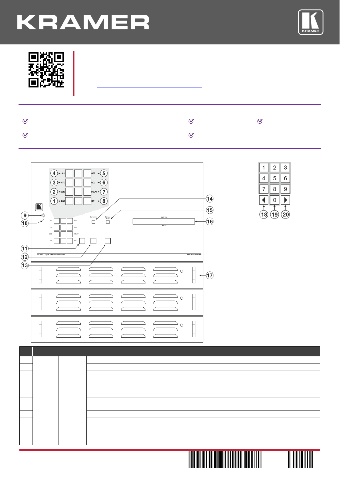
Step 2: Get to know your VS-6464DN-EM
#
Feature
Function
1
Doublefunction
Selector
Buttons
Area
Menu
Button
Functions
ESC
Press to exit the current operation.
2
EDID
Press to assign EDID channels.
3
STO
Press to store the current setup in a preset. After pressing the MENU button, this button
lights and is enabled.
4
ALL
Press to connect an input to all outputs. After pressing the MENU button, this button lights
and is enabled.
5
OFF
Press to turn off an output. After pressing the MENU button, this button lights and is
enabled.
6
RCL
Press to recall a preset. After pressing the MENU button, this button lights and is enabled.
7
DELAY
Press to set the delay between confirming an action and the execution of the action.
8
ENT
Press to complete the input-output setup when using a one-digit number instead of two
digits. For example, to enter input 5, you can press either 05 or 5, ENT.
Press to enter the options in a setup menu.
Page 2
#
Feature
Function
9
IR Receiver
Infrared remote control sensor.
10
IR LED
Lights yellow when receiving commands from the IR remote control transmitter.
11
TAKE Button
Press to confirm actions.
12
MENU Button
Press once to enable the ALL, OFF, STO and RCL buttons.
Press again to enter the configuration menu.
When in a Menu, press to cycle through the menu items.
13
LOCK Button
Press and hold for approximately 2 sec to lock/unlock the front panel buttons.
14
BREAKAWAY Button
Press to exit a menu.
15
DEFAULT SETUP Button
Press to recall the default setup.
16
OUTPUTS/INPUTS
LCD Display
Displays the outputs (upper row) switched to the selected inputs (lower row).
Displays user interface messages and menus.
17
Power Supplies
Supply power to the device. The unit includes two power supplies. A third one can be
installed.
18
◄ (Backward)
Press to shift the sliding window to the right (the LCD display only shows 13 cross-points
out of a total of 16).
19
1, 2, 3, 4, 5, 6, 7, 8, 9, 0
Numeric keypad, 1 to 0.
20
► (Forward)
Press to shift the sliding window to the left (the LCD display only shows 13 cross-points
out of a total of 16).
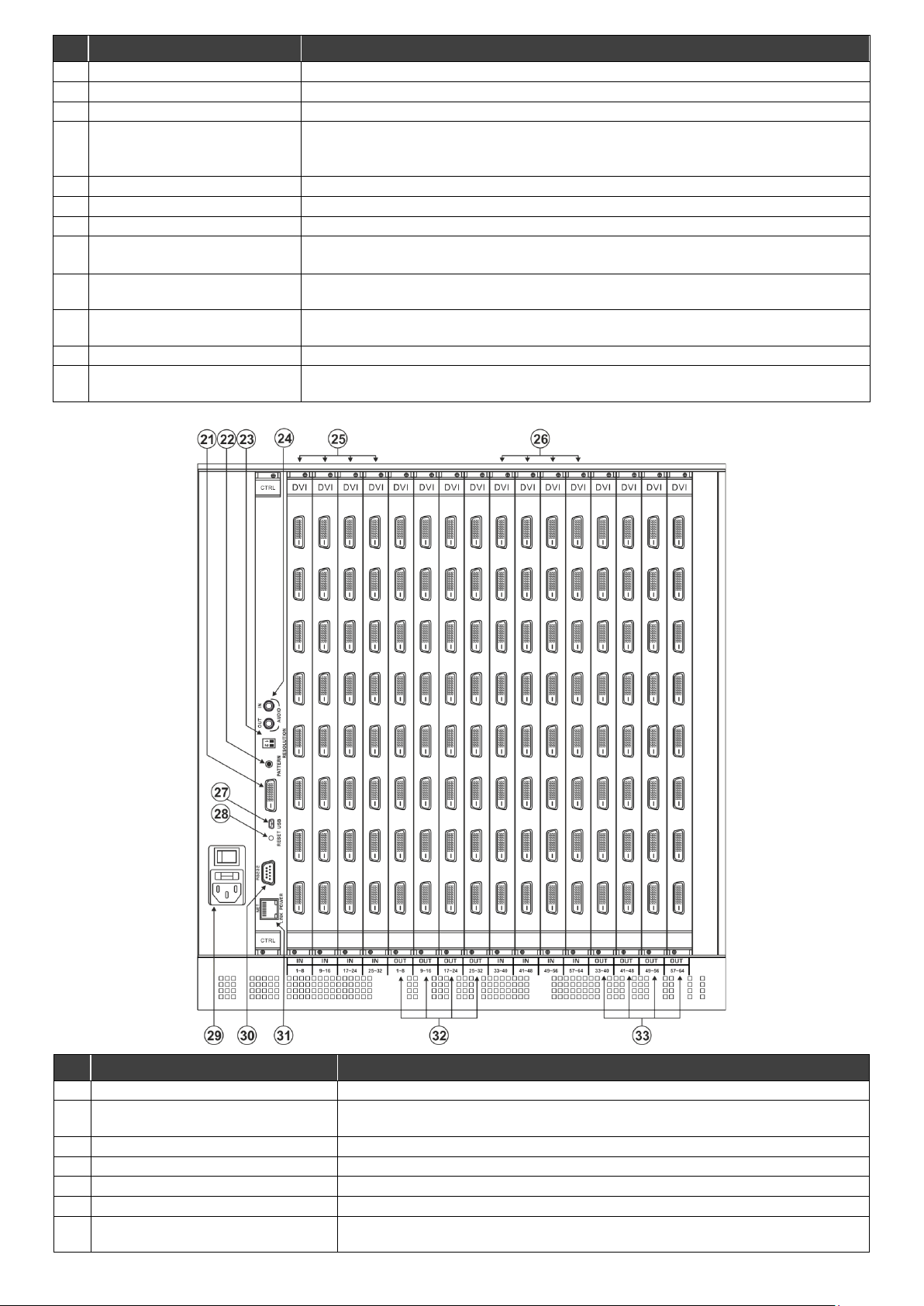
#
Feature
Function
21
Video Generator Output Connector
Connect to one of the relevant video inputs to aid in troubleshooting.
22
PATTERN Button
Press the button repeatedly to change the video pattern generated by the video
generator.
23
RESOLUTION DIP-switches
Set the resolution for video patterns generated by the video generator.
24
AUDIO OUT / IN 3.5mm Mini Jacks
Connect an audio source and speakers for testing the unit.
25
IN 1~32 Connectors
Connect to the relevant video sources, depending on the cards installed (1 to 32).
26
IN 33~64 Connectors
Connect to the relevant video sources, depending on the cards installed (33 to 64).
27
USB Virtual COM Port
USB Mini-B Connector
Connect to a PC or remote controller and perform firmware upgrade of the device
and compatible input/output cards.
Page 3
#
Feature
Function
28
RESET Button
For future use.
29
AC Mains Power Module
Connect to the power cord and mains electricity. The fuse protects the unit and the
switch is for turning the unit on and off.
30
RS-232 9-pin D-sub Port
Connect to a PC or remote controller and perform firmware upgrade of the device
and compatible input/output cards.
31
NET Ethernet RJ-45 Connector
Connect to a PC or controller via the Ethernet LAN and perform firmware upgrade of
the device and compatible input/output cards.
The LINK LED flashes when communication is active. POWER LED lights when the
interface receives power.
32
OUT 1~32 Connectors
Connect to the relevant video acceptors, depending on the cards installed (1 to 32).
33
OUT 33~64 Connectors
Connect to the relevant video acceptors, depending on the cards installed (33 to 64).
Step 3: Install the VS-6464DN-EM
To rack mount the machine, the VS-6464DN-EM is pre-assembled with
ear brackets attached to the machine.
• Ensure that the environment (e.g., maximum ambient temperature &
air flow) is compatible for the device.
• Avoid uneven mechanical loading.
• Appropriate consideration of equipment nameplate ratings should be
used for avoiding overloading of the circuits.
• Reliable earthing of rack-mounted equipment should be maintained.
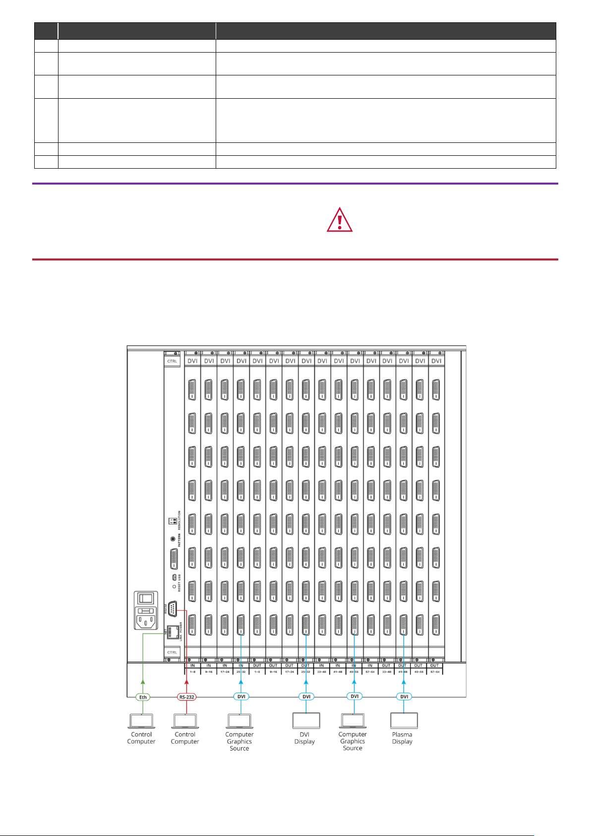
Step 4: Connect the inputs and outputs
Always switch OFF the power on each device before connecting it to your VS-6464DN-EM. For best results, we recommend
that you always use Kramer high-performance cables to connect AV equipment to the VS-6464DN-EM.
Note: the maximum number of ports may vary.
Page 4
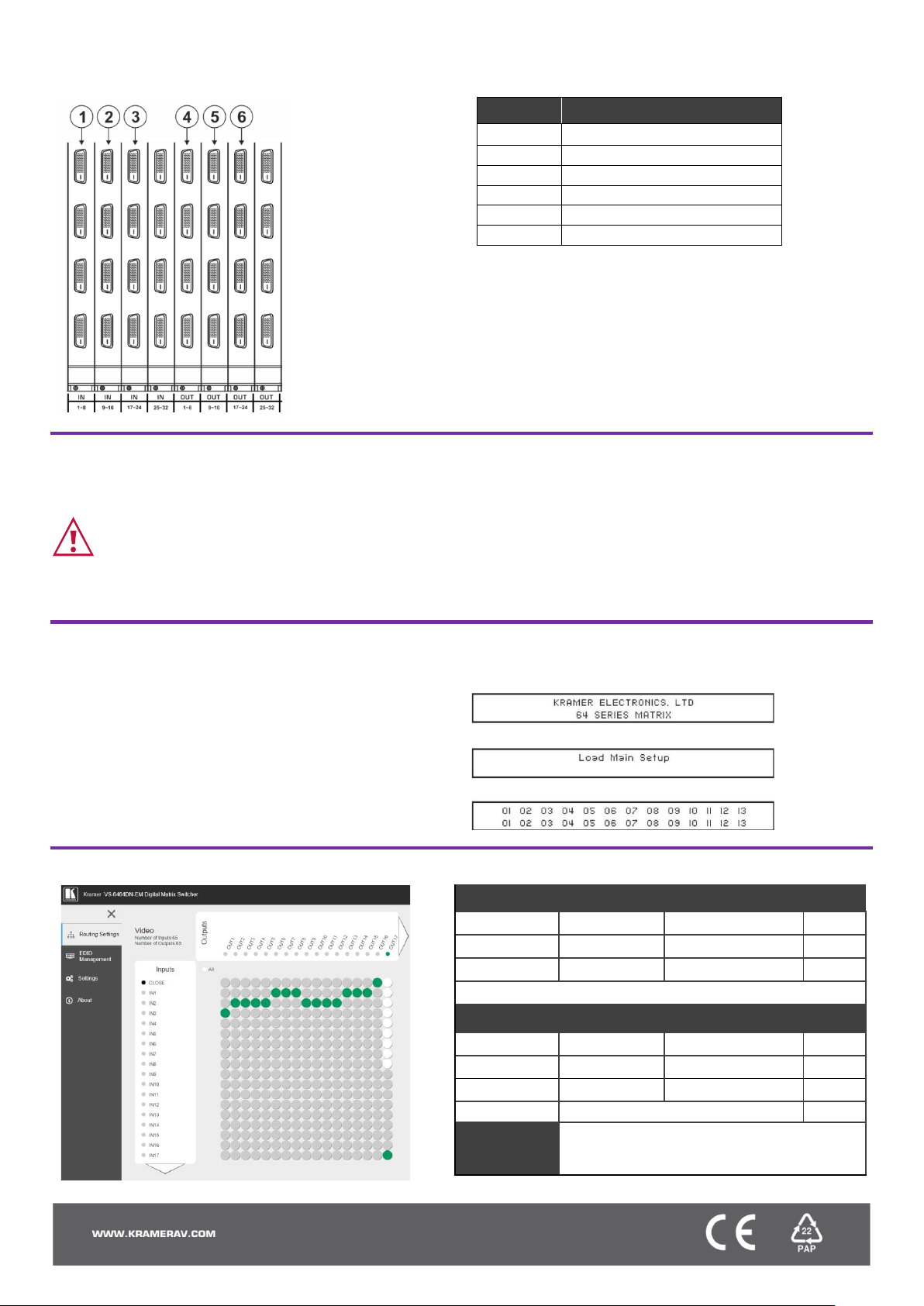
Port Numbering:
On each card there are eight physical ports numbered sequentially from top to bottom and left to right.
Note: The diagram below is a sample numbering showing only the bottom of each card.
Diagram #
Actual Port #
1
IN 1 – IN 8
2
IN 9 – IN 16
3
IN 17 – IN 24
4
OUT 1 – OUT 8
5
OUT 9 – OUT 16
6
OUT 17 – OUT 24
Step 5: Connect the power
Connect the power cord to VS-6464DN-EM and plug it into the mains electricity. Switch the VS-6464DN-EM power and then
switch on the power of connected devices.
Safety Instructions (See www.kramerav.com for updated safety information)
Caution:
• For products with relay terminals and GPI\O ports, please refer to the permitted rating for an external connection, located next to the terminal or in the User Manual.
• There are no operator serviceable parts inside the unit.
Warning:
• Use only the power cord that is supplied with the unit.
• Disconnect the power and unplug the unit from the wall before installing.
• Do not open the unit. High voltages can cause electrical shock! Servicing by qualified personnel only.
• To ensure continuous risk protection, replace fuses only according to the rating specified on the product label which located on the bottom of the unit.
Step 6: Set operation parameters
VS-6464DN-EM includes a front panel numeric
keypad for routing and control.
On power up, the last used matrix setup is loaded. To
retrieve other setups, use setup recall for a stored
configuration or default setup recall.
The LCD display can show only 13 out of the 64
available matrix combinations at once. To view any of
the matrix combinations use the ◄ or the ► buttons.
On power up, the display shows the following screens in
sequence:
Step 7: Operate via front panel buttons, RS-232, or web pages via Ethernet
RS-232 Control / Protocol 3000
Baud Rate:
115,200
Parity:
None
Data Bits:
8
Command Format:
HEX
Stop Bits:
1
Example: (Switch video input 4 to output 2): #VID 4>2
Default Ethernet Parameters
IP Address:
192.168.1.39
UDP Port #:
50000
Subnet mask:
255.255.255.0
TCP Port #:
5000
Default User:
Admin
Default Password:
Admin
Concurrent TCP Connections:
32
Full Factory
Reset
Press front panel MENU button twice. Select
Total Matrix Reset > Factory Reset. Press
TAKE twice.
 Loading...