

Kramer VS-6464DN-EM User Manual
P/N: 2900-300902 Rev 2 www.KramerAV.com
USER MANUAL
MODEL:
VS-6464DN-EM
8x8 to 64x64 Modular Multi-Format
Managed Digital Matrix Switcher

Kramer Electronics Ltd.
VS-6464DN-EM – Contents
i
Contents
Introduction 1
Getting Started 2
Overview 4
Mounting VS-6464DN-EM 10
Connecting the VS-6464DN-EM 11
Port Numbering 12
Connecting to the VS-6464DN-EM via RS-232 14
Connecting to the VS-6464DN-EM via USB (VCOM) 14
Connecting to the VS-6464DN-EM via Ethernet 14
Operating Your Video Matrix Switcher 17
Startup Display 17
Using the Selector Buttons 18
Confirming Actions 18
Switching Actions 19
Locking the Front Panel Buttons 21
Using the Configuration Menus 22
Using the Setup Menu 22
Using the Config Menu 26
Configuring the Number of Installed Input and Output Ports 32
Using the Input / Output Cards 33
Defining the HDCP-IN8-F64 / HDCP-OUT8-F64 33
Defining the DGKat-IN8-F64 / DGKat-OUT8-F64 34
Defining the F670-IN8-F64 / F670-OUT8-F64 36
Defining the F610-IN8-F64 / F610-OUT8-F64 38
Defining the DVI-IN8-F64 / DVI-OUT8-F64 39
Defining the VGAA-IN8-F64 / VGAA-OUT8-F64 40
Troubleshooting Video and Audio Problems 43
Defining the Controller and Test Card 43
Setting the Resolution of the Generated Video 44
Setting the Pattern of the Generated Video 45
Installing the Test Module 45
Troubleshooting Video Problems 46
Troubleshooting Audio Problems 47
Input / Output Card Hardware Installation Instructions 50
Installing a PS-1DN Power Supply 52
Upgrading VS-6464DN-EM and Input / Output Card Firmware 53
Upgrading Firmware Using K-Upload 53
Upgrading Firmware Using Kramer Network 54
Technical Specifications 55
VS-6464DN-EM Chassis 55
Quick VS-6464DN-EM Card Comparison 55
Default Settings 57
Default Communication Parameters 57
Factory Default EDID 57
Protocol 3000 62
Understanding Protocol 3000 Commands 63
Protocol 3000 Syntax 64
Protocol 3000 Commands 64
Using the Packet Protocol 90

Kramer Electronics Ltd.
VS-6464DN-EM – Introduction
1
Introduction
Welcome to Kramer Electronics! Since 1981, Kramer Electronics has been providing a world
of unique, creative, and affordable solutions to the vast range of problems that confront the
video, audio, presentation, and broadcasting professional on a daily basis. In recent years, we
have redesigned and upgraded most of our line, making the best even better!
Congratulations on purchasing your Kramer VS-6464DN-EM 8x8 to 64x64 Modular
Multi-Format Managed Digital Matrix Switcher. This product, which incorporates HDMI™
technology, is ideal for:
• Professional display systems requiring video signal routing.
• Broadcast, presentation and production facilities, as well as monitoring in large
duplication systems.
• Rental/staging applications.
Throughout this user manual the chassis configuration is shown with 64 DVI inputs and 64
DVI outputs as a representation only.
The following cards are available and may be mixed in the same chassis:
• HDCP-IN8-F64 / HDCP-OUT8-F64
(see Defining the HDCP-IN8-F64 / HDCP-OUT8-F64 on page 33)
• DGKat-IN8-F64 / DGKat-OUT8-F64
(see Defining the DGKat-IN8-F64 / DGKat-OUT8-F64 on page 34)
• F670-IN8-F64 / F670-OUT8-F64
(see Defining the F670-IN8-F64 / F670-OUT8-F64 on page 36)
• F610-IN8-F64 / F610-OUT8-F64
(see Defining the F610-IN8-F64 / F610-OUT8-F64 on page 38)
• DVI-IN8-F64 / DVI-OUT8-F64
(see Defining the DVI-IN8-F64 / DVI-OUT8-F64 on page 39)
• VGAA-IN8-F64 / VGAA-OUT8-F64
(see Defining the VGAA-IN8-F64 / VGAA-OUT8-F64 on page 40)
The F670-IN8/OUT8-F64 cards are fully compatible with the Kramer 670T/670R and
671T/671R HDMI/DVI transmitters and receivers for non-HDCP content.
The terms HDMI, HDMI High-Definition Multimedia Interface, and the HDMI Logo are trademarks or registered trademarks of HDMI Licensing Administrator, Inc.

Kramer Electronics Ltd.
VS-6464DN-EM – Introduction
2
Getting Started
We recommend that you:
• Unpack the equipment carefully and save the original box and packaging materials for
possible future shipment.
• Review the contents of this user manual.
Go to www.kramerav.com/downloads/VS-6464DN-EM to check for up-to-date user manuals,
application programs, and to check if firmware upgrades are available (where appropriate).
Achieving the Best Performance
To achieve the best performance:
• Use only good quality connection cables (we recommend Kramer high-performance,
high-resolution cables) to avoid interference, deterioration in signal quality due to poor
matching, and elevated noise levels (often associated with low quality cables).
• Do not secure the cables in tight bundles or roll the slack into tight coils.
• Avoid interference from neighboring electrical appliances that may adversely influence
signal quality.
• Position your VS-6464DN-EM away from moisture, excessive sunlight and dust.
This equipment is to be used only inside a building. It may only be connected to other equipment that
is installed inside a building.

Kramer Electronics Ltd.
VS-6464DN-EM – Introduction
3
Safety Instructions
Warning: Class 1 laser product
• Invisible laser radiation present.
• Avoid long-term viewing of laser.
• Avoid the use of magnifying viewing aids or instruments (such as binoculars, telescopes,
microscopes and magnifying lenses, but not spectacles or contact lenses).
• Avoid placing optical devices in the emitted beam that could cause the concentration of
the laser radiation to be increased.
Caution:
• This equipment is to be used only inside a building. It may only be connected to other
equipment that is installed inside a building.
• For products with relay terminals and GPI\O ports, please refer to the permitted rating
for an external connection, located next to the terminal or in the User Manual.
• There are no operator serviceable parts inside the unit.
Warning:
• Use only the power cord that is supplied with the unit.
• Disconnect the power and unplug the unit from the wall before installing.
• Do not open the unit. High voltages can cause electrical shock! Servicing by qualified
personnel only.
• To ensure continuous risk protection, replace fuses only according to the rating
specified on the product label which located on the bottom of the unit.
Recycling Kramer Products
The Waste Electrical and Electronic Equipment (WEEE) Directive 2002/96/EC aims to reduce
the amount of WEEE sent for disposal to landfill or incineration by requiring it to be collected
and recycled. To comply with the WEEE Directive, Kramer Electronics has made
arrangements with the European Advanced Recycling Network (EARN) and will cover any
costs of treatment, recycling and recovery of waste Kramer Electronics branded equipment on
arrival at the EARN facility. For details of Kramer’s recycling arrangements in your particular
country go to our recycling pages at www.kramerav.com/support/recycling/.
About Fast Switching
Older display devices require a longer time between the loss of one digital signal and the
introduction of another, as well as a physical disconnection of the interconnecting cable in
order to be able to detect and adjust to the new video attributes and parameters. Normal
switching, therefore, introduced a 5V signal disconnection along with a delay in switching.
Many newer display devices, however, are now capable of accepting “on-the-fly” switching.
Depending on the display device in use, the VS-6464DN-EM allows for fast switching (minor
reset and the connection kept alive) and extra fast switching (no reset and the connection
kept alive), see Config Menu—Setting Output Port Parameters on page 29. Using the fast and
extra fast switching modes allows for fraction-of-a-second switching times when using high
performance display devices or when using a scaler on the video output.

Kramer Electronics Ltd.
VS-6464DN-EM – Introduction
4
About Power Connect™
The Power Connect™ feature here means that the VS-6464DN-EM can supply power to the
TP transmitters and receivers (for example, the TP-573 and TP-574) as long as the devices
are within 90m (270ft) of each other. The Power Connect™ feature applies as long as the
cable can carry power and the distance does not exceed 90m on standard CAT 5 cable. For
longer distances, a heavier gauge cable should be used (a TP cable is still suitable for the
video/audio transmission, but not for feeding the power at these distances).
Overview
The Kramer VS-6464DN-EM is a high performance managed matrix switcher chassis for AV
signals. The unit is modular and populated from 8 x 8 to 64 x 64 ports in increments of eight
inputs and/or eight outputs. The unit supports various signals, depending on the type of cards
installed, and includes two (optional three) redundant power supplies and a controller and
testing module that can monitor and test any input or output in the matrix. It features a very
high bandwidth of up to 3.4Gbps (for the chassis only, effective bandwidth of the system
depends on the input / output cards, see Using the Input / Output Cards on page 33) that
ensures transparent performance even in the most critical applications. The cards re-clock
and equalize the signals and the chassis can route any or all inputs to any or all outputs
simultaneously.
The VS-6464DN-EM is highly configurable – you can add or remove inputs and outputs
independently in groups of eight and mix different types of input/output cards in the same
chassis. For example, you can configure a device as an 8 x 24 or a 64 x 8 matrix switcher to
exactly suit your needs.
The VS-6464DN-EM features:
• Full 64 x 64 non-blocking matrix array to switch any of the 64 input digital signals to any
or all of the 64 outputs (see Connecting the VS-6464DN-EM on page 11).
• Easy access to 60 pre-set memory locations for quick access to user-defined setups.
• Fast switching on outputs to reduce or remove switching delay.
• Support for redundant, hot swappable power supplies.
• Simple firmware upgrade of compatible cards (see Upgrading VS-6464DN-EM and Input
/ Output Card Firmware on page 53).
• Seamless integration with Kramer Network for switching, card status, port status,
firmware upgrades (of compatible cards), and more.
• A 40 character by 2 line LCD that shows the operational status or the configuration
menu.
• A lock function to prevent tampering with the front panel.
• A default EDID (Extended Display Identification Data) for each input.
• EDID Capture – Copies and stores the EDID from a display device.
• Non-volatile EDID storage.

Kramer Electronics Ltd.
VS-6464DN-EM – Introduction
5
• Kramer Core™ – Flexible infrastructure conversion. Copper, fiber or Twisted Pair, all can
be used at the same time according to input/output module selection. The matrix
receives signals from compatible Kramer transmitters, automatically converts between
available infrastructure options and sends the signals to compatible Kramer receivers.
• Max. Data Rate – 10.2Gbps (3.4Gbps per graphic channel) when using compatible
cards.
• HDTV Compatible.
• HDCP Compliant – With DVI (HDCP), F670, and DGKat modules.
• HDMI Support.
• DGKat™ Signal Integration – Kramer’s unique technology for converting TMDS as well
as control and communication to signals that run over twisted pair cables. For optimum
range and performance using, use recommended Kramer cables, available at
www.kramerav.com/product/VS-6464DN-EM
• Kramer Equalization & re-Klocking™ Technology – Rebuilds the digital signal to travel
longer distances.
• Optional Fast Switching Support – For fraction of a second switching.
• Modular & Easily Configurable Platform – Input or output module types can be mixed
and added in increments of 8 from 8x8 up to 64x64.
• Versatile Selection of Modules – Including DVI, HDCP (HDMI over DVI connector),
HDMI over Fiber, DVI over Fiber, VGA and DGKat (HDMI over twisted pair).
• Kramer Protocol 3000.
• Flexible Configuration – To disable HDCP support and convert between HDMI and DVI.
You can operate the VS-6464DN-EM via the front panel buttons or remotely via:
• RS-232 or USB (VCOM) serial commands transmitted by a touch screen system, PC or
other serial controller.
• Ethernet over a LAN.
• Kramer Network enterprise management platform.
The VS-6464DN-EM is a sophisticated device but has nevertheless been designed to be
simple to operate using an intuitive front panel keypad. For details of how to route inputs to
outputs, see Switching Actions on page 19.
The VS-6464DN-EM is housed in a 19" rack-mountable enclosure.
Kramer Electronics Ltd.
VS-6464DN-EM – Introduction
6
Defining the VS-6464DN-EM 8x8 to 64x64 Modular Multi-Format Managed Digital Matrix Switcher
This section defines the front and rear panels of the VS-6464DN-EM.
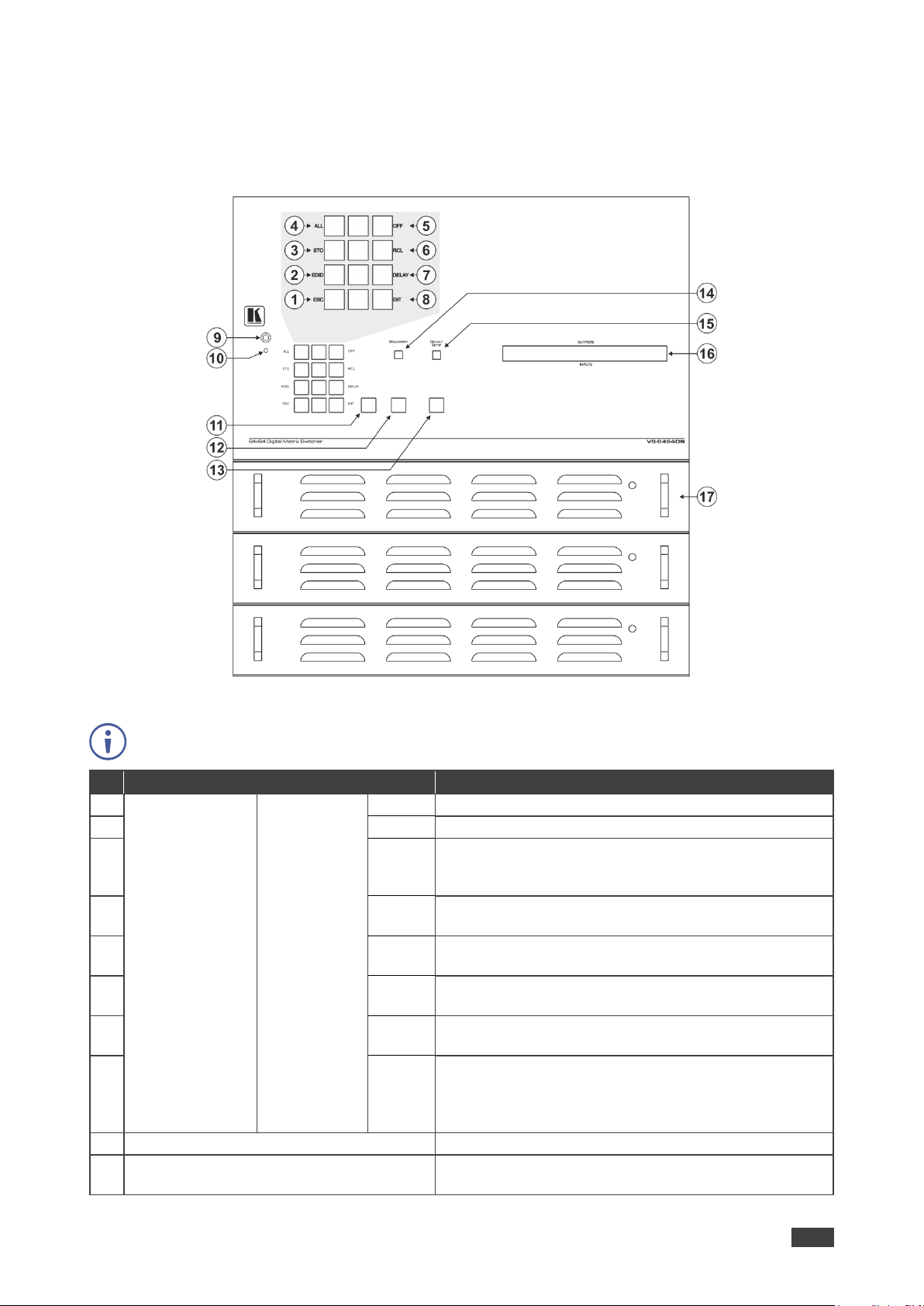
Figure 1: VS-6464DN-EM Front Panel
Buttons 11, 12 and 13 function as the TAKE, MENU and LOCK buttons respectively.
#
Feature
Function
1
Double-function
Selector Buttons
Area
Menu Button
Functions
ESC
Press to exit the current operation.
2
EDID
Press to assign EDID channels.
3
STO
Press to store the current setup in a preset. After
pressing the MENU button, this button lights and is
enabled.
4
ALL
Press to connect an input to all outputs. After pressing
the MENU button, this button lights and is enabled.
5
OFF
Press to turn off an output. After pressing the MENU
button, this button lights and is enabled.
6
RCL
Press to recall a preset. After pressing the MENU
button, this button lights and is enabled.
7
DELAY
Press to set the delay between confirming an action
and the execution of the action.
8
ENT
Press to complete the input-output setup when using a
one-digit number instead of two digits. For example, to
enter input 5, you can press either 05 or 5, ENT.
Press to enter the options in a setup menu.
9
IR Receiver
Infrared remote control sensor (for future use).
10
IR LED
Lights yellow when receiving commands from the IR
remote control transmitter (for future use).

Kramer Electronics Ltd.
VS-6464DN-EM – Introduction
7
11
TAKE Button
Press to confirm actions (see Confirming a Switching
Action on page 19).
12
MENU Button
Press once to enable the ALL, OFF, STO and RCL
buttons (see Using the Configuration Menus
on page 22).
Press again to enter the configuration menu (see Using
the Config Menu on page 26).
When in a Menu, press to cycle through the menu
items.
13
LOCK Button
Press and hold for approximately 2 sec to lock/unlock
the front panel buttons (see Locking the Front Panel
Buttons on page 21).
14
BREAKAWAY Button
Press to exit a Menu (see Using the Configuration
Menus on page 22).
15
DEFAULT SETUP Button
Press to recall the default setup (see Recalling the
Default Setup on page 21).
16
OUTPUTS/INPUTS
LCD Display
Displays the outputs (upper row) switched to the
selected inputs (lower row), (see Startup Display
on page 17).
Displays user interface messages and menus.
17
Power Supplies
Supply power to the device. The unit includes two
power supplies. A third one can be installed.
Figure 2: VS-6464DN-EM Front Panel Numeric Keypad
#
Feature
Function
18
◄ (Backward)
Press to shift the sliding window to the right (the LCD display only shows 13
cross-points out of a total of 16).
19
1, 2, 3, 4, 5, 6, 7, 8,
9, 0
Numeric keypad, 1 to 0.
20
► (Forward)
Press to shift the sliding window to the left (the LCD display only shows 13
cross-points out of a total of 16).
Kramer Electronics Ltd.
VS-6464DN-EM – Introduction
8
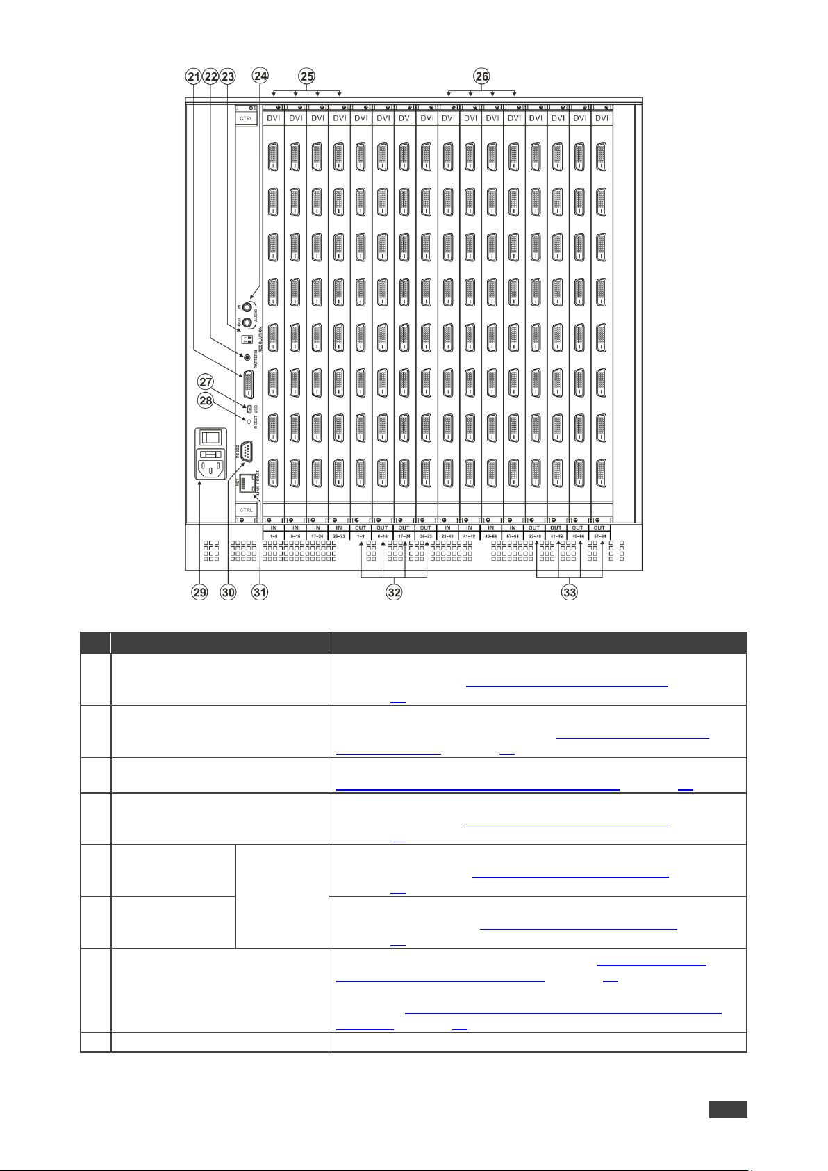
Figure 3: VS-6464DN-EM Rear Panel Showing DVI cards
#
Feature
Function
21
Test Module DVI Molex 24-pin
Video Connector
Connect to one of the relevant video inputs/outputs to aid in
troubleshooting (see Troubleshooting Video Problems
on page 46).
22
PATTERN Button
Press the button repeatedly to change the video pattern
generated by the Test module (see Setting the Pattern of the
Generated Video on page 45).
23
RESOLUTION DIP-switches
Set the resolution for video generated by the Test module (see
Setting the Resolution of the Generated Video on page 44).
24
Test Module 3.5mm Mini Jack
Unbalanced Analog Audio
Connector
Connect to one of the relevant audio inputs/outputs to aid in
troubleshooting (see Troubleshooting Audio Problems
on page 47).
25
IN 1~32
Connectors
INPUTS
Connect to the relevant video sources, depending on the cards
installed (1 to 32, see Connecting the VS-6464DN-EM
on page 11).
26
IN 33~64
Connectors
Connect to the relevant video sources, depending on the cards
installed (33 to 64, see Connecting the VS-6464DN-EM
on page 11).
27
USB Virtual COM Port
USB Mini-B Connector
Connect to a PC or remote controller (see Connecting to the
VS-6464DN-EM via USB (VCOM) on page 14) and perform
firmware upgrade of the device and compatible input/output
cards (see Upgrading VS-6464DN-EM and Input / Output Card
Firmware on page 53).
28
RESET Button
For future use.
Kramer Electronics Ltd.
VS-6464DN-EM – Introduction
9
#
Feature
Function
29
AC Mains Power Module
Power supply 1: Fuse holder and power cord socket. Connect to
the AC mains supply.
30
RS-232 9-pin D-sub Port
Connect to a PC or remote controller (see Connecting to the
VS-6464DN-EM via RS-232 on page 14) and perform firmware
upgrade of the device and compatible input/output cards (see
Upgrading VS-6464DN-EM and Input / Output Card Firmware
on page 53).
31
NET Ethernet RJ-45 Connector
Connect to a PC or controller via the Ethernet LAN (see
Connecting to the VS-6464DN-EM via Ethernet on page 14) and
perform firmware upgrade of the device and compatible
input/output cards (see Upgrading VS-6464DN-EM and Input /
Output Card Firmware on page 53).
LINK LED flashes when communication is active. POWER LED
lights when the interface receives power.
32
OUT 1~32
Connectors
OUTPUTS
Connect to the relevant video acceptors, depending on the cards
installed (1 to 32, see Connecting the VS-6464DN-EM
on page 11).
33
OUT 32~64
Connectors
Connect to the relevant video acceptors, depending on the cards
installed (33 to 64, see Connecting the VS-6464DN-EM
on page 11).
Kramer Electronics Ltd.
VS-6464DN-EM – Mounting VS-6464DN-EM
10
Mounting VS-6464DN-EM
This section provides instructions for mounting VS-6464DN-EM. Before installing, verify that
the environment is within the recommended range:
• Operation temperature – 0 to 40C (32 to 104F).
• Storage temperature – -40 to +70C (-40 to +158F).
• Humidity – 10% to 90%, RHL non-condensing.
• VS-6464DN-EM must be placed upright in the correct horizontal position.
Caution:
• Mount VS-6464DN-EM before connecting any cables or power.
Warning:
• Ensure that the environment (e.g., maximum ambient temperature & air flow) is
compatible for the device.
• Avoid uneven mechanical loading.
• Appropriate consideration of equipment nameplate ratings should be used for avoiding
overloading of the circuits.
• Reliable earthing of rack-mounted equipment should be maintained.
To mount the VS-6464DN-EM on a rack
Attach both ear brackets by removing the screws from each side of the
machine and replacing those screws through the ear brackets or place
the machine on a table.
For more information go to www.kramerav.com/downloads/VS-6464DN-EM

Kramer Electronics Ltd.
VS-6464DN-EM – Connecting the VS-6464DN-EM
11
Connecting the VS-6464DN-EM
Always switch off the power to each device before connecting it to your VS-6464DN-EM. After
connecting your VS-6464DN-EM, connect its power and then switch on the power to each
device.
You do not have to connect all the inputs and outputs, connect only those that are required.
In the following example, only two inputs and two outputs are connected.
The configuration of DVI input/output cards shown in Figure 4 is merely a sample
representation and different input / output cards may be mixed as required (for limitations, see
Port Numbering on page 12). Exactly the same principles apply to installations using other
card types.
To connect the VS-6464DN-EM, as illustrated in the example in Figure 4, do the following:
1. Connect up to 64 DVI video sources (for example, computer graphics sources).
2. Connect up to 64 DVI video acceptors, (for example, a plasma display and DVI LCD
display).
3. If required, connect a PC or remote controller to the RS-232 port (see Connecting to the
VS-6464DN-EM via RS-232 on page 14) and/or the Ethernet port (see Connecting to the
VS-6464DN-EM via Ethernet on page 14).
4. Connect the power cord.
5. If necessary, review and set the system configuration using the Menu (see Using the
Configuration Menus on page 22).
Given an input signal that is HDCP encoded, the VS-6464DN-EM outputs a signal only if the
output port to which it is switched supports HDCP.
Kramer Electronics Ltd.
VS-6464DN-EM – Connecting the VS-6464DN-EM
12
Figure 4: Connecting the VS-6464DN-EM
Port Numbering
On each card there are eight physical ports numbered sequentially from top to bottom and left
to right. Figure 5 displays a sample numbering showing only the bottom of each card.
Kramer Electronics Ltd.
VS-6464DN-EM – Connecting the VS-6464DN-EM
13
Figure 5: Sample Port Numbering
Diagram #
Actual Port Number
1
IN 1 – IN 8
2
IN 9 – IN 16
3
IN 17 – IN 24
4
OUT 1 – OUT 8
5
OUT 9 – OUT 16
6
OUT 17 – OUT 24
EDID Numbering Examples
The following EDID configuration is based on the port numbering shown in Figure 5 and lists
requested switching configurations and their results.
EDID Request
EDID Sent
From OUT 21
Blank (256 bytes of 0xFF)
From IN 25
None (error message displayed)
AV data flow is: source > VS-6464DN-EM > display. EDID information flow is: display >
VS-6464DN-EM > source, which means that the EDID input is the display side and the EDID
output is the AV source side. This is the reverse of the AV data flow direction.
When assigning EDIDs, note that the top row of the LCD display labeled OUTPUTS
relates to the ports connected to the sources (AV inputs), and the bottom row of the
LCD display labeled INPUTS relates to the ports connected to displays (AV outputs).
In Figure 6, the EDID from EDID input 8 (VS-6464DN-EM Output port 8) has been assigned
to all EDID outputs (VS-6464DN-EM Input ports).
Figure 6: EDID Numbering Assignment

Kramer Electronics Ltd.
VS-6464DN-EM – Connecting the VS-6464DN-EM
14
Connecting to the VS-6464DN-EM via RS-232
You can connect to the VS-6464DN-EM via an RS-232 connection using, for example, a PC.
Note that a null-modem adapter/connection is not required.
To connect to the VS-6464DN-EM via RS-232:
• Connect the RS-232 9-pin D-sub rear panel port on the VS-6464DN-EM unit via a 9-wire
straight cable (only pin 2 to pin 2, pin 3 to pin 3, and pin 5 to pin 5 need to be connected)
to the RS-232 9-pin D-sub port on your PC.
Connecting to the VS-6464DN-EM via USB (VCOM)
The device’s USB port can work as a virtual COM (VCOM) port. Verify that the USB port on
the PC that connects to the VS-6464DN-EM is configured as a VCOM port. You may need to
install a driver to do this. You can use a tool such as Hercules or K-Config to use Protocol
3000 commands over USB (see Protocol 3000 on page 62). You can also use K-Upload to
upgrade firmware over USB (see Upgrading Firmware Using K-Upload on page 53).
Connecting to the VS-6464DN-EM via Ethernet
You can connect to the VS-6464DN-EM via Ethernet using either of the following methods:
• Directly to the PC using a crossover cable (see Connecting the Ethernet Port Directly to
a PC on page 14).
• Via a network hub, switch, or router, using a straight-through cable (see Connecting the
Ethernet Port via a Network Hub or Switch on page 16).
If you want to connect via a router and your IT system is based on IPv6, speak to your IT
department for specific installation instructions.
Connecting the Ethernet Port Directly to a PC
You can connect the Ethernet port of the VS-6464DN-EM directly to the Ethernet port on your
PC using a crossover cable with RJ-45 connectors.
This type of connection is recommended for identifying the
VS-6464DN-EM with the factory configured default IP address.
After connecting the VS-6464DN-EM to the Ethernet port, configure your PC as follows:
1. Click Start > Control Panel > Network and Sharing Center.
2. Click Change Adapter Settings.
3. Highlight the network adapter you want to use to connect to the device and click Change
settings of this connection.
The Local Area Connection Properties window for the selected network adapter appears
as shown in Figure 7.
Kramer Electronics Ltd.
VS-6464DN-EM – Connecting the VS-6464DN-EM
15
Figure 7: Local Area Connection Properties Window
4. Highlight either Internet Protocol Version 6 (TCP/IPv6) or Internet Protocol Version 4
(TCP/IPv4) depending on the requirements of your IT system.
5. Click Properties.
The Internet Protocol Properties window relevant to your IT system appears as shown in
Figure 8 or Figure 9.
Figure 8: Internet Protocol Version 4 Properties Window
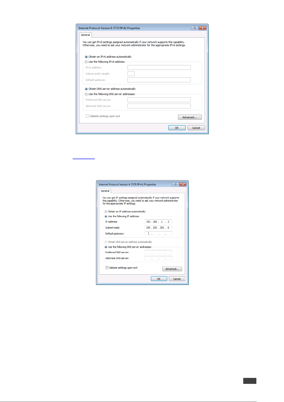
Kramer Electronics Ltd.
VS-6464DN-EM – Connecting the VS-6464DN-EM
16
Figure 9: Internet Protocol Version 6 Properties Window
6. Select Use the following IP Address for static IP addressing and fill in the details as
shown in Figure 10.
For TCP/IPv4 you can use any IP address in the range 192.168.1.1 to 192.168.1.255
(excluding 192.168.1.39) that is provided by your IT department.
Figure 10: Internet Protocol Properties Window
7. Click OK.
8. Click Close.
Connecting the Ethernet Port via a Network Hub or Switch
You can connect the Ethernet port of the VS-6464DN-EM to the Ethernet port on a network
hub or using a straight-through cable with RJ-45 connectors.
Kramer Electronics Ltd.
VS-6464DN-EM – Operating Your Video Matrix Switcher
17
Operating Your Video Matrix Switcher
This section describes:
• The startup display (see Startup Display on page 17).
• Using the selector buttons (see Using the Selector Buttons on page 18).
• Confirming actions (see Confirming Actions on page 18).
• Switching options (see Switching Actions on page 19).
• Locking the front panel (see Locking the Front Panel Buttons on page 21).
Startup Display
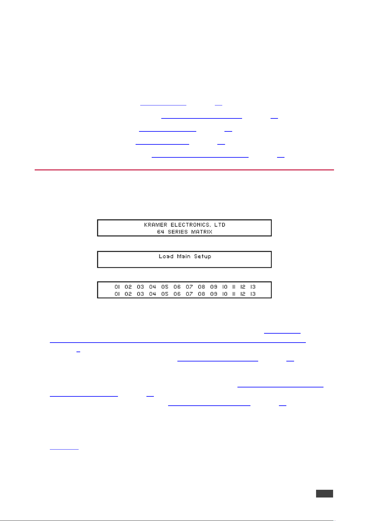
After switching on the power, the LCD display shows the following screens in sequence (text
in the LCD Display may vary according to machine settings).
Figure 11: Default Startup Status Display Sequence
The VS-6464DN-EM does not have separate output and input buttons. Instead, the front
panel includes a numeric keypad within the Selector Buttons area (see Defining the
VS-6464DN-EM 8x8 to 64x64 Modular Multi-Format Managed Digital Matrix Switcher
on page 6). This numeric keypad lets you enter both the output and input numbers as well as
various numeric configuration values (see Using the Selector Buttons on page 18).
When the unit is powered-on, the last matrix setup that was used is loaded. Use either the
setup recall (records a stored configuration from a preset, see Setup Menu—6: recall setup
XX, Recalling a Preset on page 25) or default setup recall (for quick retrieval of a commonly
used programmable default setup, see Recalling the Default Setup on page 21) functions to
retrieve other setups.
Viewing the Display
Figure 11 shows the output-input matrix on the LCD display. The LCD display can show only
13 out of the 64 available matrix combinations at once. To view any of the matrix
combinations use the ◄ or the ► buttons on the front panel to shift the sliding window to the
right or left.

Kramer Electronics Ltd.
VS-6464DN-EM – Operating Your Video Matrix Switcher
18
This sliding window functionality is enabled when:
• The switcher is in between operations (waiting for its next operation while all previous
operations are complete or cancelled).
• Recalling a setup using the ◄ or ► buttons.
When entering an output/input combination, the contents of the LCD display automatically
shift to indicate the current status of the selected output.
Using the Selector Buttons
For numbers between 1 and 9, the VS-6464DN-EM can handle two digit numbers as well as
single digit numbers. When entering a single digit number (for example 5), you can either
press 0 followed by 5, or 5 followed by ENTER.
Pressing 00 (or 0, ENTER) is only relevant for an input and is used to disconnect the currently
entered output number from the input.
For example, the following display indicates that outputs 8 and 12 are disconnected from any
input (note that the corresponding inputs in the second line are blank):
06
07
08
09
10
11
12
13
12
08 10
14
13 06
The ESC button is used to cancel an operation without affecting the current status. For
example, if you enter an incorrect number by mistake, press the ESC button to cancel the
operation.
At any stage, if no button is pressed within approximately 15 seconds, the automatic timeout
causes the VS-6464DN-EM to exit the operation and revert to the output/input display.
Confirming Actions
You can choose to work in the At Once (default, for all actions except storing/recalling) or the
Confirm mode.
In the At Once mode:
• The TAKE button does not light.
• Pressing an OUT-IN combination implements the switch without further user
confirmation.
• You save time as execution is immediate and actions require no user confirmation.
• No protection is offered to correct an erroneous action.
In the Confirm mode:
• The TAKE button lights.
• You enter an action and then confirm it by pressing the TAKE button.

Kramer Electronics Ltd.
VS-6464DN-EM – Operating Your Video Matrix Switcher
19
• Every action requires user confirmation, protecting against erroneous actions.
• Execution is postponed until you confirm the action.
Failure to press the TAKE button within a few seconds results in the action timing out
automatically.
Toggling Between the At Once and Confirm Modes
To toggle between the At Once and Confirm modes:
If the TAKE button is flashing, you cannot toggle between the At Once and Confirm modes. A
flashing TAKE button indicates that an action is currently pending confirmation.
1. Press TAKE to toggle between the At Once mode and the Confirm mode.
The TAKE button lights and actions now require user confirmation.
2. Press the lit TAKE button to toggle from the Confirm mode back to the At Once mode.
The TAKE button is no longer lit and actions no longer require user confirmation.
Confirming a Switching Action
Actions only require confirmation when the device is in the Confirm mode.
To confirm a switching action:
1. Using the numeric keypad, enter an output-input combination.
The TAKE button flashes.
2. Press the flashing TAKE button to confirm the action.
The action is confirmed and the TAKE button lights.
Switching Actions
This section describes how to:
• Switch one input to one output (see Switching One Input to One Output on page 19).
• Switch several inputs to several outputs (see Switching Several Inputs to Several
Outputs on page 20).
• Turn off several outputs (see Turning an Output Off on page 20).
Switching One Input to One Output
To switch one input to one output:
1. Using the numeric keypad, enter the required output (in this example, 12).
The following is displayed:
06
07
08
09
10
11
12
13 In__ => Out 12
The left-hand side of the display shows a section of the output/input display
automatically sliding the content to include output 12.

Kramer Electronics Ltd.
VS-6464DN-EM – Operating Your Video Matrix Switcher
20
2. Using the numeric keypad, enter the required input (in this example, 14):
▪ In the At Once mode, the switching takes place immediately and the LCD display
shows a segment of the input-output status that includes the switched input and
output (for example, 14-12).
In the Confirm mode, the LCD display shows the following:
In 14 => Out 12
Incomplete actions time out after approximately 15 seconds.
▪ In the Confirm mode, press the flashing TAKE button to switch the input to the
output.
Switching Several Inputs to Several Outputs
If you want to switch several inputs to several outputs, you must be in the Confirm mode.
In the Confirm mode you can enter a batch of several actions and then confirm the batch by
pressing TAKE once (simultaneously switching several output-input combinations).
To switch several inputs to several outputs in the Confirm mode:
1. Using the numeric keypad, enter an output-input combination.
The TAKE button flashes.
2. Enter additional output-input combinations.
The LCD display can show up to five pending actions (although the batch is not limited
to five actions), as follows:
09 => 06 05 => 07
In this example, input 9 is set to switch to output 6 and input 5 is set to switch to output
7.
3. After entering all output/input combinations, press the flashing TAKE button to confirm
the actions.
The inputs switch to the respective outputs as shown on the LCD display and the TAKE
LED is lit.
Turning an Output Off
Turning off an output means that there is no input switched to this output. This is indicated on
the display by the Input being blank underneath the relevant Output.
To turn an output off:
1. Press MENU.
The Menu buttons light and are enabled.
2. Press OFF (3) on the numeric keypad (see Figure 2).
The following message is displayed:
out__ => OFF
3. Use the numeric keypad to turn the required output off.
The output is turned off.

Kramer Electronics Ltd.
VS-6464DN-EM – Operating Your Video Matrix Switcher
21
To turn an output off in the Confirm mode:
• Repeat the steps above and then press the flashing TAKE button to confirm the action.
Alternatively, you can perform a switching operation (see Switching One Input to One
Output on page 19) and set the input to 00.
Turning Off Several Outputs
To turn off several outputs in the Confirm mode, repeat the switching actions described in
Switching Several Inputs to Several Outputs on page 20 but set the inputs to 00.
Recalling the Default Setup
You can store a commonly used setup as the default setup (see Config Menu—Store Default
Setup on page 30) which can be recalled at any time.
This is not the setup that is loaded when the unit is turned on. When the unit is turned on, the
setup that was last used before the unit was turned off is loaded.
To recall the default setup:
1. Press DEFAULT SETUP.
The DEFAULT SETUP button flashes and the following message is displayed:
recall DEFAULT setup
press FLASHING button to confirm
2. Press DEFAULT SETUP.
The following message is displayed:
all Setups and Connections change
press TAKE to confirm
The TAKE button flashes.
3. Press TAKE.
The default setup is recalled and the display reverts to the output-input display.
Locking the Front Panel Buttons
You can lock the VS-6464DN-EM to prevent tampering with the unit or prevent the settings
from being changed accidentally via the front panel buttons. When the front panel is locked,
you can still remotely operate the VS-6464DN-EM via RS-232 or Ethernet.
To lock the front panel buttons:
• Press and hold LOCK until the button lights.
The front panel buttons are locked.
To unlock the front panel buttons:
• Press and hold LOCK until the button is no longer lit.
The front panel buttons are unlocked.

Kramer Electronics Ltd.
VS-6464DN-EM – Using the Configuration Menus
22
Using the Configuration Menus
The configuration menus let you configure the VS-6464DN-EM to best suit your needs. There
are two configuration menus:
• Setup Menu—those that are accessed on a regular basis (for example, storing setups
and setting the delay), see Using the Setup Menu on page 22.
• Config Menu—those that are accessed only occasionally (for example, setting the
interface or communication protocol), see Using the Config Menu on page 26.
The following rules apply to the menu operation:
• If no selection is made within approximately 15 seconds, the operation times-out and the
display reverts to the output/input display.
• At any point in the Menu, press ESC to move up one level or press BREAKAWAY to exit
the Menu altogether.
• At any point in the Menu, only buttons that are active light or flash.
All of the procedures in this section assume that you are starting the procedure from the
standard, operational output/input display.
Using the Setup Menu
The Setup Menu provides access to settings that are regularly changed and comprises the
following options:
• 1: inXX=>ALL, switching one input to all outputs (see Setup Menu—1: inXX=>ALL,
Switching One Input to all Outputs on page 23).
• 3: outXX=OFF, turning off an output (see Setup Menu—3: outXX=>OFF, Turning an
Output Off on page 23).
• 7: EDID, assignment to an output (see Setup Menu—7: EDID, Assignment to an Input
on page 23).
• 9: Delay setting for an output (see Setup Menu—9: Delay, Setting for an Output
on page 24).
• 4: store setup XX, storing the setup in a preset (see Setup Menu—4: store setup XX,
Storing the Setup in a Preset on page 25).
• 6: recall setup XX, recalling a preset (see Setup Menu—6: recall setup XX, Recalling a
Preset on page 25).

Kramer Electronics Ltd.
VS-6464DN-EM – Using the Configuration Menus
23
Setup Menu—1: inXX=>ALL, Switching One Input to all Outputs
This option switches one input to all outputs.
To switch one input to all outputs:
1. Press MENU.
The Setup Menu options are displayed.
2. Press 1 (ALL) on the numeric keypad (see Figure 2).
The following is displayed:
in__ => ALL
3. Using the numeric keys, enter the input to be switched to all outputs.
The TAKE button flashes.
4. Press TAKE.
The selected input is switched to all outputs. The display reverts to the output/input
display showing that the selected input is switched to all outputs.
Setup Menu—3: outXX=>OFF, Turning an Output Off
This option turns an output off.
To turn an output off:
1. Press MENU.
The Setup Menu options are displayed.
2. Press 3 (OFF) on the numeric keypad (see Figure 2).
The following is displayed:
out__ => OFF
3. Using the numeric keys, enter the output to be turned off.
The TAKE button flashes.
4. Press TAKE.
The selected output is turned off. The display reverts to the output/input display showing
that the selected output is turned off with the input being blank.
Setup Menu—7: EDID, Assignment to an Input
This option assigns an EDID to between one and eight inputs in non-volatile storage. More
than eight EDID assignments must be assigned in multiple batches.
Each input on the VS-6464DN-EM has a factory default EDID loaded (see Factory Default
EDID on page 57). The EDID for each input can be changed independently via the menu
(described below) or by uploading an EDID binary file to each input via the RS-232 port.
It is necessary to have a display/device connected to the output from which you want to read
the EDID. Failure to do so results in the default EDID being written to storage.

Kramer Electronics Ltd.
VS-6464DN-EM – Using the Configuration Menus
24
To assign an EDID to between one and eight inputs:
1. Press MENU.
The Setup Menu options are displayed.
2. Press 7 (EDID) on the numeric keypad (see Figure 2).
The following is displayed:
SETUP EDID
ENTER to View EDID and Set EDID
3. Press ENT.
The current EDID matrix configuration is displayed.
4. Using the numeric keys, enter the input in which to store the EDID (in this example, 08),
and enter the output (in this example, 05) from which to read the EDID.
The following is displayed:
01
02
03
04
05
06
07
08
05
out05 => in08
The TAKE button flashes.
5. Repeat Step 4 for up to eight inputs.
6. Press TAKE.
The EDID is stored and passed through to the input.
The display reverts to the output/input display.
To view the EDID assignments:
1. Press MENU.
The Setup Menu options are displayed.
2. Press 7 (EDID) on the numeric keypad (see Figure 2).
The following is displayed:
SETUP EDID
ENTER to View EDID and Set EDID
3. Press ENT.
The current EDID matrix configuration is displayed. In this example, input 07 is assigned
to output 05, all other EDID values are default.
05 06 07 08 09 10
05
Setup Menu—9: Delay, Setting for an Output
This option sets the time delay for an output which lapses between entering a switching action
and the execution of the action. This delay can be set for each output independently. The
delay is defined in units of 200ms and ranges from 0 to 15, providing delays of between 0 and
3 seconds (15 x 200ms = 3 seconds).
To set the execution delay for an output:
1. Press MENU.
The Setup Menu options are displayed.

Kramer Electronics Ltd.
VS-6464DN-EM – Using the Configuration Menus
25
2. Press 9 (DELAY) on the numeric keypad (see Figure 2).
The output/delay times display is shown.
3. Using the numeric keys, enter the output (in this example, 03).
The following is displayed:
01
02
03
04
05
06
07
08 DLY__ =>out03
4. Using the numeric keys, enter the number of delay units.
5. Press TAKE.
The selected output delay is set. The display reverts to the output/input display.
Setup Menu—4: store setup XX, Storing the Setup in a Preset
This option stores the current setup in a preset (1 to 60).
To store the current setup in a preset:
1. Press MENU.
The Setup Menu options are displayed.
2. Press 4 (STO) on the numeric keypad (see Figure 2).
The following is displayed:
store => __
3. Using the numeric keys, enter the preset (1 to 60) in which to store the current setup.
The following is displayed:
Wait …..
After a few seconds, if the preset is not empty, the following is displayed:
SETUP NOT EMPTY
CONFIRM
The TAKE button flashes.
4. Press TAKE.
The setup is stored in the selected preset for subsequent recall. The display reverts to
the output/input display.
Setup Menu—6: recall setup XX, Recalling a Preset
This option recalls a stored configuration from a preset (1 to 60).
To recall a stored configuration:
1. Press MENU.
The Setup Menu options are displayed.
2. Press 6 (RCL) on the numeric keypad (see Figure 2).
The following is displayed:
recall <= __
3. Using the numeric keys, enter the preset (in this example, 02) to recall.
The following is displayed:
Wait …..

Kramer Electronics Ltd.
VS-6464DN-EM – Using the Configuration Menus
26
After a few seconds, the following is displayed on the right hand side:
CONFIRM
RECALL <= 02
The TAKE button flashes.
4. Press TAKE.
The preset is recalled. The display reverts to the output/input display.
Using the Config Menu
The Config Menu provides access to configuration settings that are not regularly changed and
comprises the following options:
• Input signal detection display (Config Menu—Input Signal Detection Display on page 27)
• Input port parameter setting (Config Menu—Setting Input Port Parameters on page 27).
• Output load detection display (see Config Menu—Output Load Detection Display
on page 28).
• Output port parameter setting (Config Menu—Setting Output Port Parameters
on page 29).
• Storing the default setup (Config Menu—Store Default Setup on page 30).
• Total matrix reset (Config Menu—Total Matrix Reset on page 30).
• Display firmware versions (Config Menu—Display Firmware Versions on page 31).
To enter the Config Menu:
• Press MENU twice. The MENU button lights and the following message is displayed:
Start configuration menu
MENU to view setups ENTER to change them
When browsing through the configuration menu, enabled buttons light or flash.
Use the Config Menu as follows:
1. Press the MENU button to cycle through the menu items.
The LCD display shows the current status of the selected menu item.
2. Press the ENT button to enter a submenu.
3. After entering a submenu, you can select between several options.
Select an option by pressing one of the illuminated buttons in the Selector Buttons area.
4. After selecting the desired option, a description of the desired change is displayed and
the TAKE button flashes.
5. Press the flashing TAKE button to confirm the change.
A description of the current state is displayed for about one second. The unit
automatically switches to the next item in the menu.

Kramer Electronics Ltd.
VS-6464DN-EM – Using the Configuration Menus
27
Config Menu—Input Signal Detection Display
This option displays a list of inputs and indicates on which of them signals have been
detected.
To display a list of inputs that have detected signals:
1. Press MENU twice.
The following message is displayed:
start configuration menu
MENU to view setup ENTER to change them
2. Press MENU.
The following is displayed:
IN:
01
02
03
04
05
06
07
08
09
10
11
OUT:
o X o o o o X o o o X
o indicates that a signal is detected and X indicates that no signal is detected on the
relevant input.
3. Do one of the following:
▪ Press BREAKAWAY to exit the Config Menu.
▪ Wait approximately 15 seconds for the operation to time out.
▪ Press MENU to move to the next Config Menu option.
Config Menu—Setting Input Port Parameters
This option sets input port-specific parameters. Ports that show an X have no parameters
available to modify. Ports that show an o have parameters available to modify. The
parameters that are available, such as, audio balance, depend on the type of card installed
and whether the card is an input or an output card (see Using the Input / Output Cards
on page 33 for information on the input / output cards and their parameters).
To set parameters for a port:
1. Press MENU twice.
The following message is displayed:
start configuration menu
MENU to view setup ENTER to change them
2. Press MENU until a display is shown similar to the following:
IN:
01
02
03
04
05
06
07
08
09
10
11
SET:
X X X X o o X X o o X
X indicates that there are no modifiable parameters for the associated port and o indicates
that there are modifiable parameters for the associated port.
3. Press TAKE to enter the list of ports.
The cursor flashes on a selected port.
4. Select the required port using the left and right arrow buttons.
 Loading...