

Kramer VS-6464DN User Manual

Kramer Electronics, Ltd.
USER MANUAL
Model:
VS-6464DN
64x64 Digital Matrix Switcher

Contents
i
Contents
1 Introduction 1
2 Getting Started 1
2.1 Quick Start 2
3 Overview 3
3.1 Defining EDID 4
3.2 About the Power Connect™ Feature 4
3.3 Recommendations for Best Performance 5
3.4 Redundant Power Supplies 5
4 Defining the VS-6464DN 64x64 Digital Matrix Switcher 5
4.1 Using the IR Transmitter 9
5 Installing the VS-6464DN in a Rack 10
6 Connecting the VS-6464DN 64x64 Digital Matrix Switcher 11
6.1 Port Numbering 12
6.1.1 Port Switching and EDID Numbering Examples 13
6.2 Connecting to the VS-6464DN via RS-232 14
6.3 Connecting to the VS-6464DN via Ethernet 14
6.3.1 Connecting the Ethernet Port directly to a PC 14
6.3.2 Connecting to the Ethernet Port via a Network Switch/Hub 16
7 Operating Your Video Matrix Switcher 17
7.1 Startup Display 17
7.1.1 Viewing the Display 17
7.2 Using the Selector Buttons 18
7.3 Confirming Actions 18
7.3.1 Toggling between the At Once and Confirm Modes 19
7.3.2 Confirming a Switching Action 19
7.4 Switching Actions 19
7.4.1 Switching one Input to one Output 19
7.4.2 Switching Several Inputs to Several Outputs 20
7.4.3 Turning an Output Off 20
7.4.4 Turning Off Several Outputs 21
7.4.5 Recalling the Default Setup 21
7.5 Locking the Front Panel Buttons 22
8 Using the Configuration Menu 22
8.1 Using the Setup Menu 22
8.1.1 Setup Menu—1: inXX=>ALL, Switching one Input to all Outputs 23
8.1.2 Setup Menu—3: outXX=>OFF, Turning an Output Off 23
8.1.3 Setup Menu—7: EDID, Assignment to an Input 23
8.1.4 Setup Menu—9: Delay, Setting for an Output 24
8.1.5 Setup Menu—4: store setup XX, Storing the Setup in a Preset 25
8.1.6 Setup Menu—6: recall setup XX, Recalling a Preset 26

KRAMER: SIMPLE CREATIVE TECHNOLOGY
Contents
ii
8.2 Using the Config Menu 26
8.2.1 Config Menu—Input Signal Detection Display 27
8.2.2 Config Menu—Output Load Detection Display 27
8.2.3 Config Menu—Interface Configuration 28
8.2.4 Config Menu—Interface Reply Configuration 28
8.2.5 Config Menu—Protocol Configuration 29
8.2.6 Config Menu—Store Default Setup 29
8.2.7 Config Menu—Total Matrix Reset 30
8.2.8 Config Menu—Display Firmware Versions 31
9 Configuring the Number of Installed Input and Output Ports 31
10 Using the Video Generator to Troubleshoot Video Problems 32
10.1 Installing the Video Generator 32
10.2 Setting the Resolution of the Generated Video 32
10.3 Setting the Pattern of the Generated Video 33
10.4 Using the Video Generator to Troubleshoot Video Problems 33
10.4.1 Testing the Projector Output 34
10.4.2 Testing the Output Signal Path to the Projector 34
10.4.3 Testing the Input and Output Signal Path to the Projector 34
11 I/O Card Hardware Installation Instructions 35
12 Power Supply Installation 37
13 Upgrading the VS-6464DN Firmware 37
14 Technical Specifications 37
15 Default Communication Parameters 39
16 Factory Default EDID 39
16.1 DVI Input Card 39
16.2 DVI (HDCP) Input Card 40
17 Communication Protocols 42
Figures
Figure 1: VS-6464DN 64x64 Digital Matrix Switcher Front Panel 6
Figure 2: VS-6464DN
Front Panel Numeric Keypad 7
Figure 3: VS-6464DN 64x64 Digital Matrix Switcher Rear Panel Showing DVI Cards 8
Figure 4: Connecting the VS-6464DN
11
Figure 5: Sample Port Numbering 13
Figure 6: Local Area Connection Properties Window 15
Figure 7: Internet Protocol (TCP/IP) Properties Window 16
Figure 8: Default Startup Status Display Sequence 17
Figure 9: Resolution DIP-switch 33
Figure 10: Signal Paths for Isolating problems 34
Figure 11: Inserting the Card into a Slot 35
Figure 12: Card Handles 36

Contents
iii
Tables
Table 1: VS-6464DN 64x64 Digital Matrix Switcher Front Panel Features 7
Table 2: VS-6464DN Front Panel Numeric Keypad Labels 7
Table 3: VS-6464DN
64x64 Digital Matrix Switcher Rear Panel Features 9
Table 4: Port Numbering 13
Table 5: EDID Configuration Requests and Results 13
Table 6: Available PC Resolutions for Generated Video (Jumper off) 33
Table 7: Available HD Resolutions for Generated Video (Jumper on, default) 33
Table 8: Technical Specifications of the 64x64 Digital Matrix Switcher 37
Table 9: Technical Specifications of VS-6464DN Compatible Cards 38
Table 10: Default Communication Parameters for the VS-6464DN 39
Table 11: Input and Output Switching Hex Codes 42

Introduction
1
1 Introduction
Welcome to Kramer Electronics! Since 1981, Kramer Electronics has been
providing a world of unique, creative, and affordable solutions to the vast
range of problems that confront the video, audio, presentation, and
broadcasting professional on a daily basis. In recent years, we have
redesigned and upgraded most of our line, making the best even better! Our
1,000-plus different models now appear in 11 groups
1
Congratulations on purchasing your Kramer VS-6464DN 64x64 Digital
Matrix Switcher. This product is ideal for the following typical applications:
that are clearly
defined by function.
• Professional display systems requiring video signal routing
• Broadcast, presentation and production facilities, as well as
monitoring in large duplication systems
• Rental/staging applications
The package includes the following items:
• VS-6464DN 64x64 Digital Matrix Switcher
• Power cord
• Kramer RC-IR3 infrared remote control transmitter (including the
required batteries and a separate user manual
2
)
• This user manual
2
Note: Throughout this user manual the chassis configuration is shown with
64 DVI inputs and 64 DVI outputs as a representation only. The following
cards are available and may be mixed in the same chassis:
• DVI
• DVI (HDCP)
• DVI (over 4LC fiber optic cable)
2 Getting Started
We recommend that you:
• Unpack the equipment carefully and save the original box and
packaging materials for possible future shipment
• Review the contents of this user manual
• Use Kramer high-performance high-resolution cables
1
1 GROUP 1: Distribution Amplifiers; GROUP 2: Switchers and Routers; GROUP 3: Control Systems; GROUP 4:
Format/Standards Converters; GROUP 5: Range Extenders and Repeaters; GROUP 6: Specialty AV Products; GROUP 7:
Scan Converters and Scalers; GROUP 8: Cables and Connectors; GROUP 9: Room Connectivity; GROUP 10: Accessories
and Rack Adapters; GROUP 11: Sierra Products
2 Download up-to-date Kramer user manuals from http://www.kramerelectronics.com
KRAMER: SIMPLE CREATIVE TECHNOLOGY
Getting Started
2
• Use only the power cord that is supplied with this machine
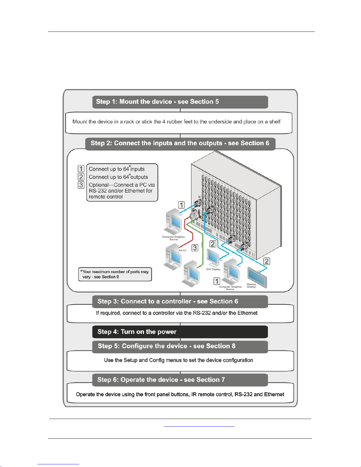
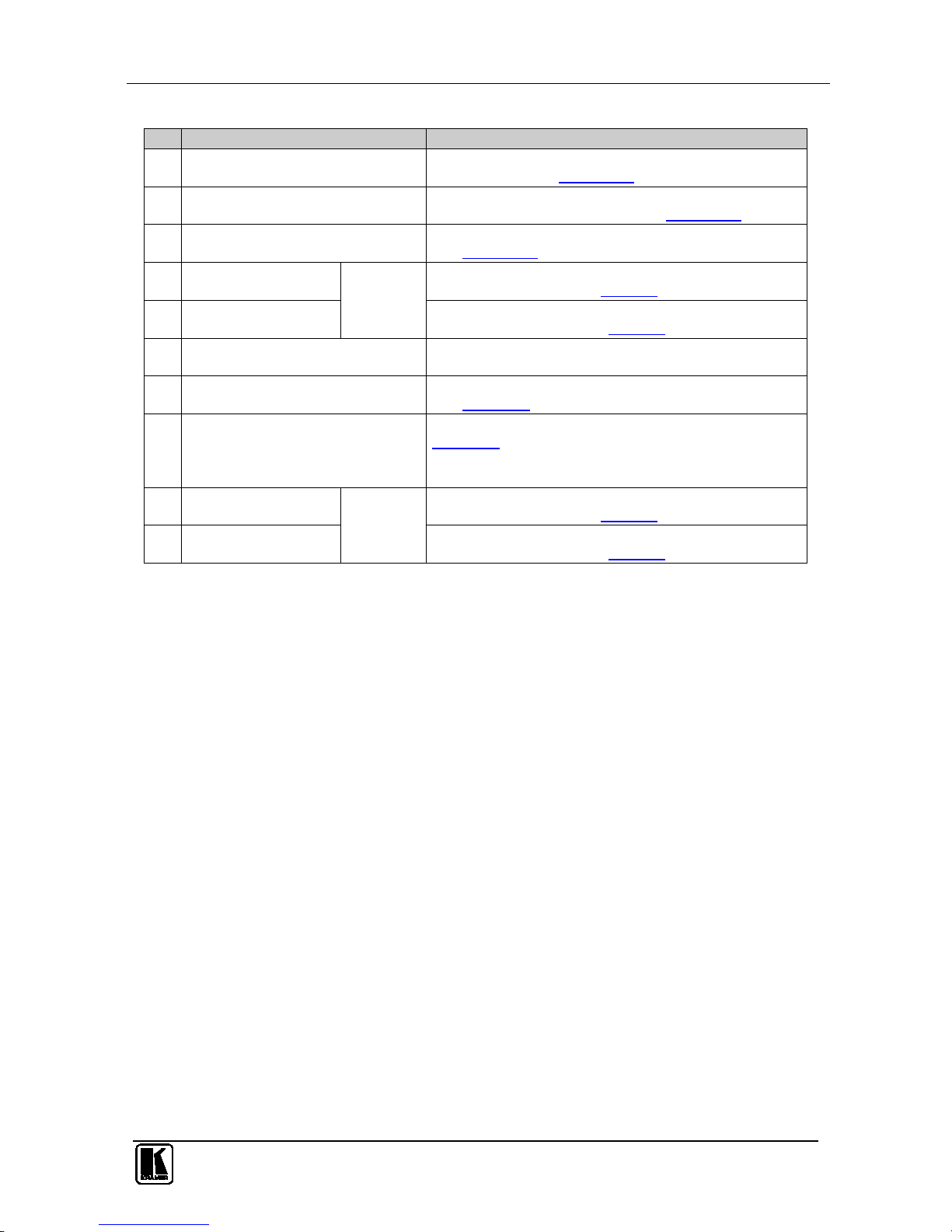
2.1 Quick Start
The following quick start chart summarizes the basic setup and operation
steps.
1 The complete list of Kramer cables is available from http://www.kramerelectronics.com

Overview
3
3 Overview
The Kramer VS-6464DN is a high performance matrix switcher chassis that
supports up to 64 x 64 ports
1
for various signals (depending on the type of
cards installed). It features a very high bandwidth
2
The VS-6464DN is highly configurable–you can add or remove inputs and
outputs independently in groups of eight and mix different types of
input/ouput cards in the same chassis. For example, you can configure a
device as a 8 x 24 or a 64 x 8 matrix switcher to exactly suit your needs.
of up to 3.2Gbps (for the
chassis only, effective bandwidth of the system depends on the I/O cards)
that ensures transparent performance even in the most critical applications.
The cards re-clock and equalize the signals and the chassis can route any or
all inputs to any or all outputs simultaneously.
The VS-6464DN features:
• Full 64 x 64 non-blocking matrix array to switch any of the 64 input
digital signals to any or all of the 64 outputs (with limitations, see 6)
• Easy access to 59 preset memory locations for quick access to user-
defined setups
• The Kramer 2000 Protocol for serial control
• A 40 character by 2 line LCD that shows the operational status or the
configuration menu
• A lock function to prevent tampering with the front panel
• A default EDID (Extended Display Identification Data) for each input
• I-EDIDPro™ Kramer Intelligent EDID Processing™ – Intelligent
EDID handling and processing algorithm ensures plug and play
operation for DVI/HDMI systems
• Non-volatile EDID storage
• Kramer Core™—FLEXIBLE INFRASTRUCTURE
CONVERSION! Copper, fiber or Twisted Pair–all can be used at the
same time according to input/output module selection. The matrix
receives signals from compatible Kramer transmitters, automatically
converts between available infrastructure options and sends the
signals to compatible Kramer receivers
• Equalization and re-clocking on all card types
• Support for redundant power-supplies
1 Can also be configured for other sizes (up to a maximum of 64 x 64)
2 For maximum bandwidth supported by each card type see Technical Specifications in Section
13

KRAMER: SIMPLE CREATIVE TECHNOLOGY
Overview
4
You can operate the VS-6464DN via the front panel buttons
1
• RS-232 serial commands transmitted by a touch screen system, PC or
other serial controller
or remotely
via:
• Ethernet over a LAN
• The infrared remote control transmitter
The VS-6464DN is housed in a 19" rack-mountable enclosure.
To achieve the best performance:
• Connect only good quality connection cables, thus avoiding
interference, deterioration in signal quality due to poor matching, and
elevated noise levels (often associated with low quality cables)
• Avoid interference from neighboring electrical appliances that may
adversely influence signal quality
• Position your Kramer VS-6464DN in a location free from moisture
and away from excessive sunlight and dust
3.1 Defining EDID
The Extended Display Identification Data (EDID
2
3.2 About the Power Connect™ Feature
) is a data-structure
provided by a display, to describe its capabilities to a graphics card (that is
connected to the display’s source). The EDID enables the video source to
“know” what kind of monitor is connected to the output. The EDID
includes the manufacturer’s name, the product type, the timing data
supported by the display, the display size, luminance data and (for digital
displays only) the pixel mapping data.
The Power Connect™ feature here means that the VS-6464DN can supply
power to the TP transmitters and receivers (for example, the TP-573 and
TP-574) as long as the devices are within 90m (270ft) of each other. The
Power Connect™ feature applies as long as the cable can carry power and
the distance does not exceed 90m on standard CAT 5 cable. For longer
distances, heavier gauge cable should be used
3
.
1 The VS-6464DN is a sophisticated device but has been designed to be as simple as possible to operate. Due to space
limitations on the front panel, 128 input/output selector buttons are instead substituted by a keypad. For details of how to
route inputs to outputs, see Section
7.2
2 Defined by a standard published by the Video Electronics Standards Association (VESA)
3 TP cable is still suitable for the video/audio transmission, but not for feeding the power at these distances).

Defining the VS-6464DN 64x64 Digital Matrix Switcher
5
3.3 Recommendations for Best Performance
To achieve the best performance:
• Use only good quality connection cables to avoid interference,
deterioration in signal quality due to poor matching, and elevated
noise levels (often associated with low quality cables)
• Do not secure the cables in tight bundles or roll the slack into tight
coils
• Avoid interference from neighboring electrical appliances that may
adversely influence signal quality and position your Kramer VS-
6464DN away from moisture, excessive sunlight and dust
3.4 Redundant Power Supplies
The VS-6464DN is supplied with three power supplies accessible from the
front of the device (see
Figure 1) and which are held in place with thumb-
screws. The power supplies operate in a redundant mode whereby the
failure of any one power supply does not cause the device to stop operating.
Note: The device must have at least two working power supplies to operate
correctly.
4 Defining the VS-6464DN 64x64 Digital Matrix Switcher
Figure 1, Table 1, Figure 2 and Table 2 define the front panel of the
VS-6464DN.
KRAMER: SIMPLE CREATIVE TECHNOLOGY
Defining the VS-6464DN 64x64 Digital Matrix Switcher
6
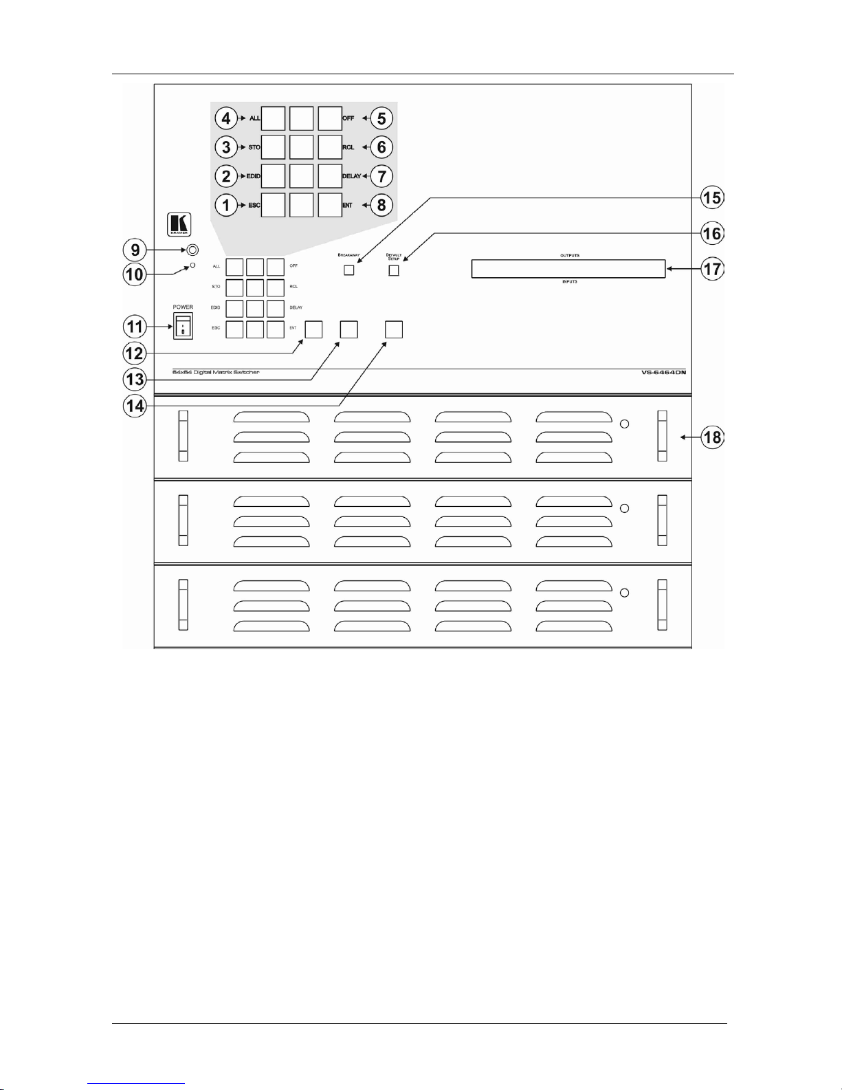
Figure 1: VS-6464DN 64x64 Digital Matrix Switcher Front Panel
Note: Buttons 12, 13 and 14 function as the TAKE, MENU and LOCK
buttons respectively.
Defining the VS-6464DN 64x64 Digital Matrix Switcher
7
Table 1: VS-6464DN 64x64 Digital Matrix Switcher Front Panel Features
#
Feature
Function
1
Doublefunction
Selector
Buttons
Area
Menu
Button
Functions
ESC Press to exit the current operation
2 EDID Press to assign EDID channels
3 STO1Press to store the current setup in the preset
4 ALL1 Press to connect an input to all outputs
5 OFF1 Press to turn off an output
6 RCL1 Press to recall a preset
7 DELAY Press to set the delay between confirming an action and execution of the action
8 ENT Press to complete the input-output setup when using a one-digit number instead of
two digits
2
Press to enter the options in a setup menu
.
9 IR Receiver Infrared remote control sensor
10 IR LED Lights yellow when receiving commands from the IR remote control transmitter
11 POWER Switch Switch to turn the device on and off
12 TAKE Button Press to confirm actions (see Section 7.3.2)
13 MENU Button Press once to enable the ALL, OFF STO and RCL buttons (see Section 8).
Press again to enter the configuration menu (see Section
8.2).
When in a Menu, press to cycle through the menu items
14 LOCK Button Press and hold for approximately 2 sec to lock/unlock the front panel buttons (see
Section
7.5)
15 BREAKAWAY Button Press to exit a Menu (see Section 8)
16 DEFAULT SETUP Button Press to recall the default setup (see Section 7.4.5)
17 OUTPUTS/INPUTS
LCD Display
Displays the outputs (upper row) switched to the selected inputs (lower row), (see
Section
7.1).
Displays user interface messages and menus
18 Power Supplies Three power supplies providing redundancy (see Section 3.4)
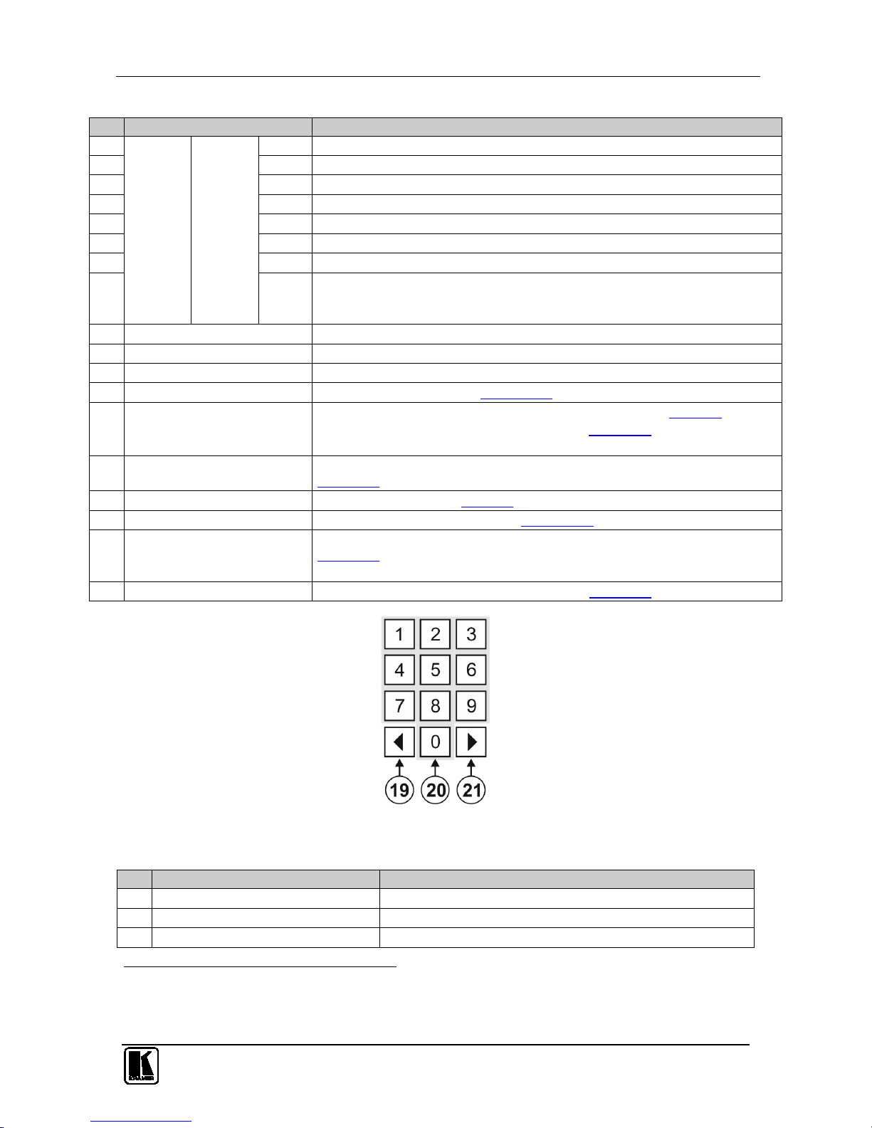
Figure 2: VS-6464DN Front Panel Numeric Keypad
Table 2: VS-6464DN Front Panel Numeric Keypad Labels
#
Feature
Function
19 ◄ (Backward) Press to shift the sliding window to the right3
20 1, 2, 3, 4, 5, 6, 7, 8, 9, 0 Numeric keypad, 1 to 0
21 ► (Forward) Press to shift the sliding window to the left
3
1 After pressing the MENU button, this button lights and is enabled
2 For example, to enter input 5, you can either press 05 or 5, ENT
3 Since the LCD display is large enough to show only 13 cross-points out of a total of 64
KRAMER: SIMPLE CREATIVE TECHNOLOGY
Defining the VS-6464DN 64x64 Digital Matrix Switcher
8
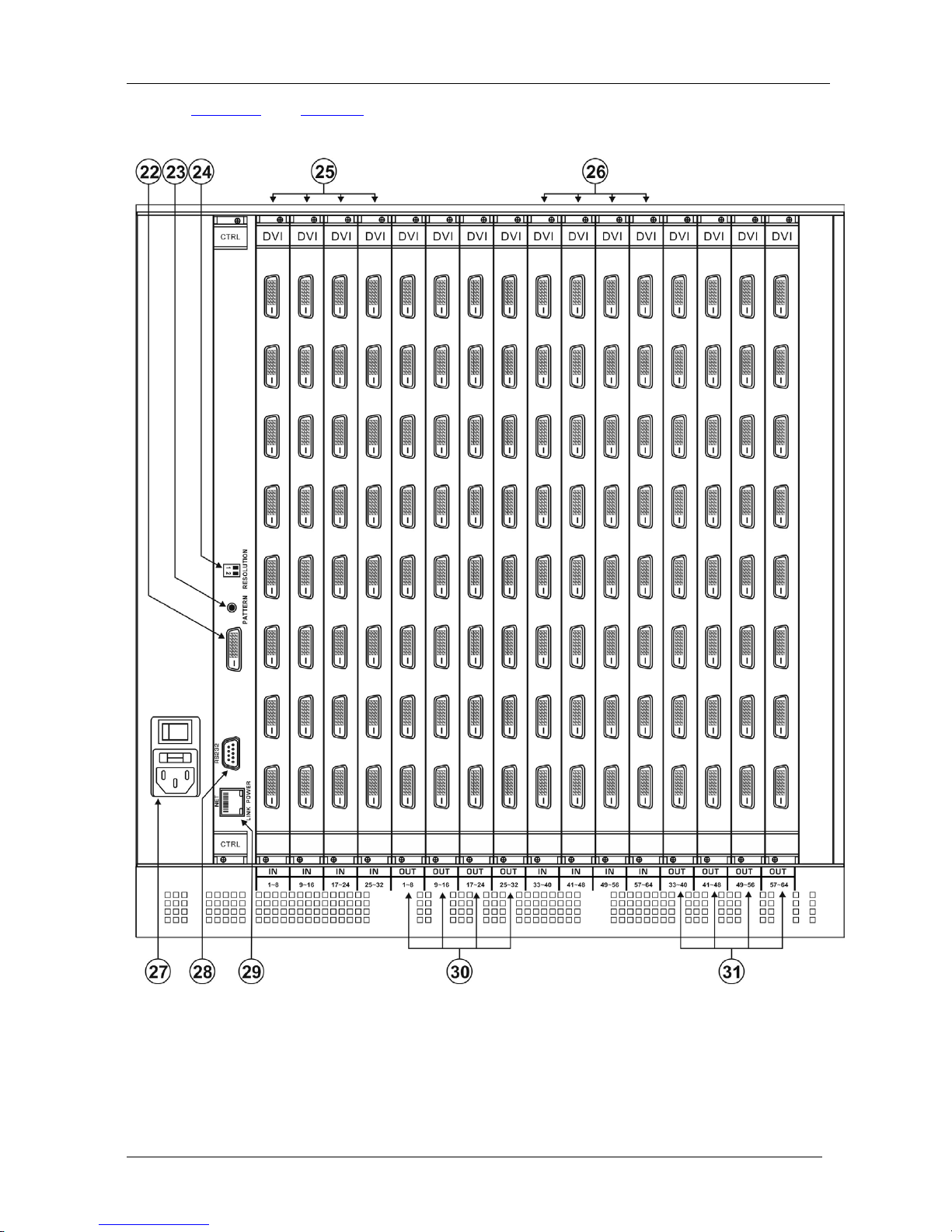
Figure 3 and Table 3 define the rear panel of the VS-6464DN showing DVI
cards installed as an example.
Figure 3: VS-6464DN 64x64 Digital Matrix Switcher Rear Panel Showing DVI Cards
Defining the VS-6464DN 64x64 Digital Matrix Switcher
9
Table 3: VS-6464DN 64x64 Digital Matrix Switcher Rear Panel Features
#
Feature
Function
22 Video Generator Output Connector Connect to one of the relevant video inputs to aid in
troubleshooting (see Section
10.4)
23 PATTERN Button Press the button repeatedly to change the video pattern
generated by the video generator (see Section
10.3)
24 RESOLUTION DIP-switches Set the resolution for video generated by the Test module
(see Section
10.2)
25 IN 1~32 Connectors
INPUTS
Connect to the relevant video sources, depending on the
cards installed (1 to 32, see Section
6)
26 IN 33~64 Connectors Connect to the relevant video sources, depending on the
cards installed (33 to 64, see Section
6)
27 AC Mains Power Module Fuse holder and power cord socket. Connect to the AC
mains supply
28 RS-232 9-pin D-sub Port Connects to the remote operation PC or remote controller
(see Section
6.1)
29 NET Ethernet RJ-45 Connector Connect to a PC or controller via the Ethernet LAN (see
Section
6.3).
The LINK LED flashes when communication is active.
POWER LED lights when the interface receives power
30 OUT 1~32 Connectors
OUTPUTS
Connect to the relevant video acceptors, depending on the
cards installed (1 to 32, see Section
6)
31 OUT 33~64 Connectors Connect to the relevant video acceptors, depending on the
cards installed (33 to 64, see Section
6)
4.1 Using the IR Transmitter
You can use the RC-IR3 IR transmitter to control the machine via the
built-in IR receiver on the front panel.
KRAMER: SIMPLE CREATIVE TECHNOLOGY
Installing the VS-6464DN in a Rack
10
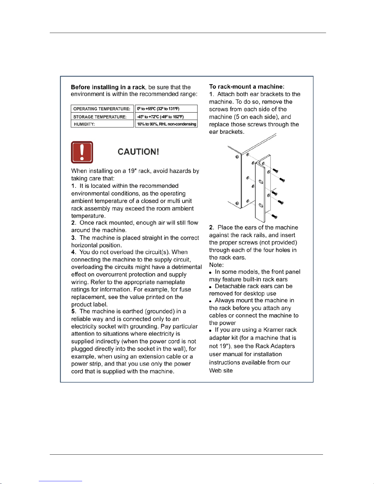
5 Installing the VS-6464DN in a Rack
This section provides instruction on rack mounting the VS-6464DN.
Connecting the VS-6464DN 64x64 Digital Matrix Switcher
11
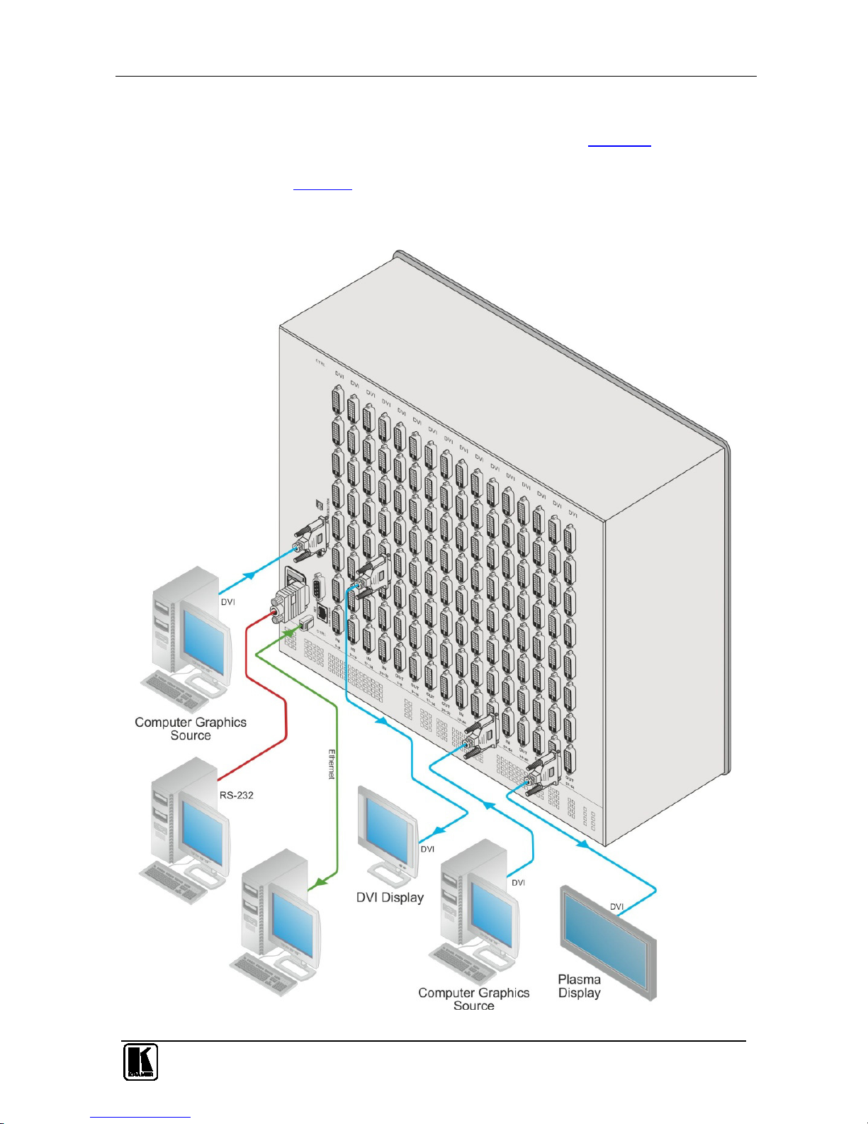
6 Connecting the VS-6464DN 64x64 Digital Matrix Switcher
The configuration of DVI input/output cards shown in Figure 4 is merely a
sample representation and different I/O cards may be mixed as required (for
limitations, see page
12). Exactly the same principles apply to installations
using DVI dual link, DVI (HDCP), DVI (over 4LC fiber cable) and HDMI
cards.
Figure 4: Connecting the VS-6464DN
 Loading...