

Page 1
VS-622DT Quick Start (P/N: 2900-301025QS REV 3)
P/N:
2900- 301025QS
Rev:
3
Scan for full manual
VS-622DT Quick Start Guide
This guide helps you install and use your VS-622DT for the first time.
Go to www.kramerav.com/downloads/VS-622DT to download the latest user manual and check if
firmware upgrades are available.
Step 1: Check what’s in the box
VS-622DT 6x2 HDMI / HDBT Audio Matrix Switcher
1 Quick start guide
1 Set of rack ears
1 Power cord
4 Rubber feet
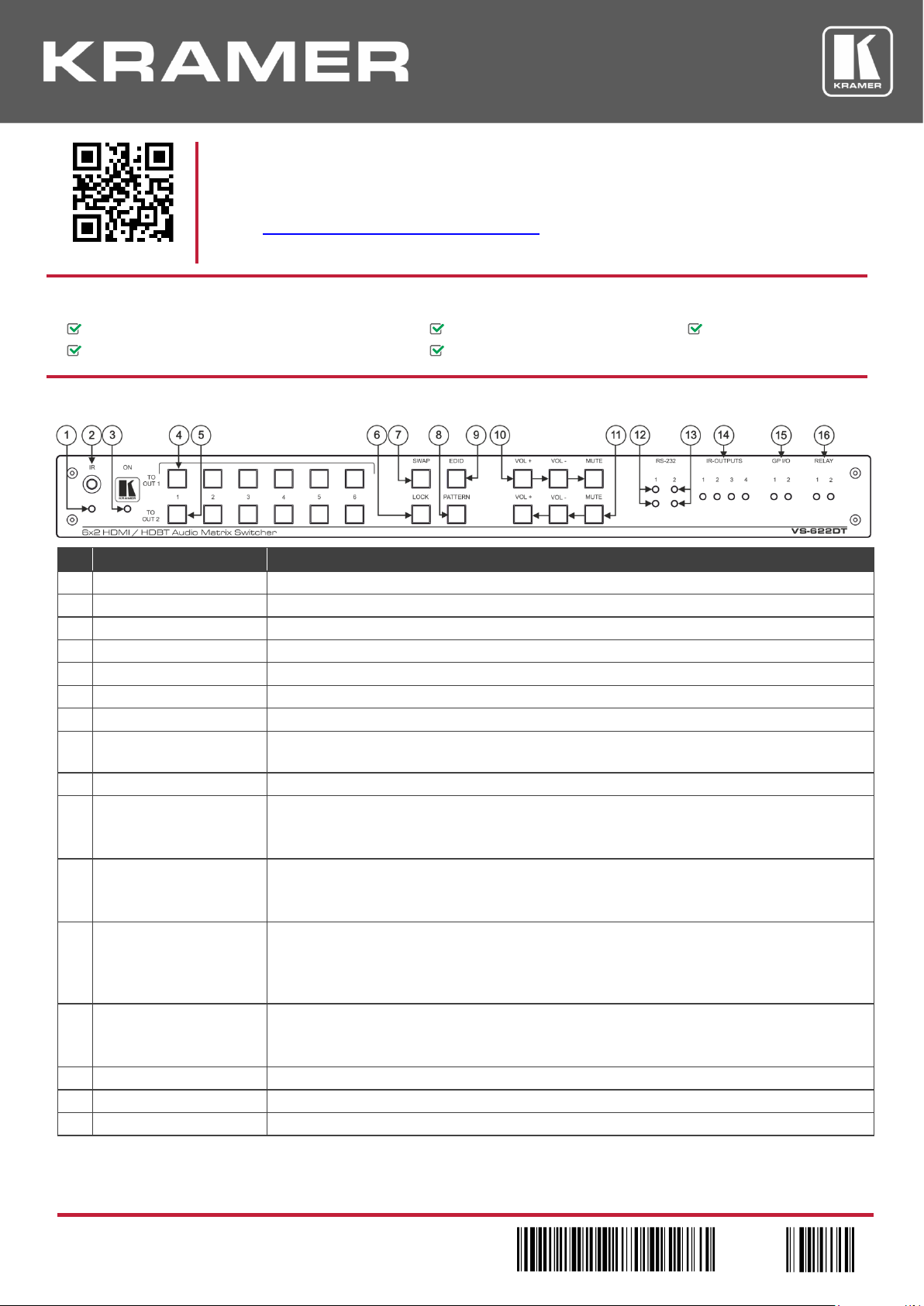
Step 2: Get to know your VS-622DT
#
Feature
Function
1
IR LED
Lights red when the unit accepts IR remote commands.
2
IR Receiver
Receives signals from the remote control transmitter.
3
ON LED
Lights when the unit is powered.
4
TO OUT 1
Press to select an input to switch to OUT 1 (from 1 to 6).
5
TO OUT 2
Press to select an input to switch to OUT 2 (from 1 to 6).
6
LOCK Button
Press to lock the front panel buttons.
7
SWAP Button
Press to swap between audio outputs.
8
PATTERN Button
Press to activate the test pattern generator. When the generator is active, press one of the input
buttons to select a test pattern.
9
EDID Button
Press to capture the EDID.
10
Output 1 Audio Buttons
VOL +: Increase output 1 volume.
VOL -: Decrease output 1 volume.
MUTE: Mute output 1 audio signal.
11
Output 2 Audio Buttons
VOL +: Increase output 2 volume.
VOL -: Decrease output 2 volume.
MUTE: Mute output 1 audio signal.
12
HDBT RS-232 LEDs
Indicates data transmission from a controller to a device connected to the transmitter via
HDBT OUT 1:
TX 1: Lights green when data is transmitted via HDBT OUT 1.
RX 1: Lights red when data is received on HDBT OUT 1.
13
EXTERNAL (Controller)
LEDs
Indicates data transmission via the RS-232 port (item 29) to the VS-622DT:
TX 2: Lights green when data is transmitted on the RS-232 port.
RX 2: Lights red when data is received on the RS-232 port.
14
IR OUTPUT LEDs (1 to 4)
Lights green when the relevant IR port transmits data.
15
GPI/O LEDs (1 to 2)
Lights green when the port is triggered.
16
RELAY LEDs (1 to 2)
Lights green when the relay is closed.
Page 2
#
Feature
Function
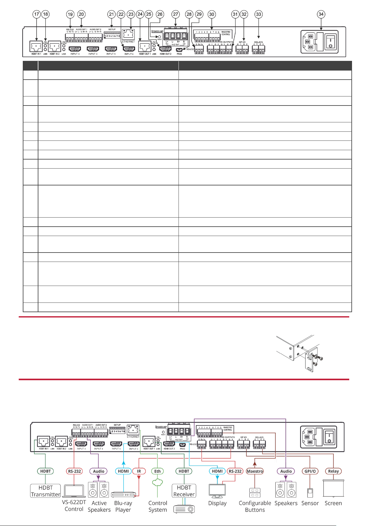
17
HDBT IN 1 RJ-45 Connectors (1 to 2)
Connect to an HDBT transmitter (for example, TP-580Txr).
18
POE STATUS and LINK LEDs (for HDBT IN 1 to 2
and HDBT OUT 1)
Light when PoE is available and a link is established.
19
Control RS-232 3-pin Terminal Block
Connect to the serial controller to control the device.
20
AUDIO OUT Balanced Stereo Audio 5-pin Terminal
Block Connectors (1 to 2)
Connect to an analog audio acceptor.
21
SETUP DIP-switches
Used to set the device behavior.
22
INPUT HDMI Connectors (3 to 6)
Connect to HDMI source (from 1 to 8).
23
ETHERNET RJ-45 Connector
Connect to a remote network controller via a LAN.
24
HDBT OUT1 RJ-45 Connector
Connect to an HDBT receiver (for example, TP-580Rxr)
25
HDMI OUT 2 Connector
Connect to an HDMI acceptor.
26
RESET Switch
Press and hold while powering on the device to reset to factory
default parameters.
27
Hi-Z OUT Terminal Block Connectors
Lo-Z – connect stereo output to Lo-Z speakers:
L+ and L- to the left speaker; R+R- to the right speaker.
Hi-Z (70V or 100V) – connect Hi-Z and COM to mono Hi-Z
speakers.
28
PROG Mini USB Connector
Connect to a PC to perform firmware upgrade.
29
RS-232 (G, Rx, Tx) Terminal Block Connector
Connect to an RS-232 controlled device.
30
MAESTRO CONTROL 9-pin Terminal Block
Connectors
Connect to configurable buttons (configured via the Automation
page), such as the RC-21TB.
31
IR OUTPUT 2-pin Terminal Block Connectors (1 to 4)
Connect to IR blasters/emitters using cables up to 80m (260ft) long.
32
GPI/O 2-pin Terminal Block Connectors (1 to 2)
Connect to controllable sensors or devices (for example, motion
sensors). This port can be configured as a digital input, digital
output, or analog input.
33
RELAY 2-pin Terminal Block Connectors (1 to 2)
Connect to a relay controllable device, (for example, a motorized
projection screen).
34
Mains Power Connector, Fuse, and Switch
Connect to the mains supply.
Step 3: Install VS-622DT
Install VS-622DT using one of the following methods:
• Remove the three screws from each side of the unit, reinsert those screws through the
rack ears and mount on a 19" rack.
• Attach the rubber feet and place the unit on a flat surface.
Step 4: Connect the inputs and outputs
Always switch OFF the power on each device before connecting it to your VS-622DT. For best results, we recommend that you
always use Kramer high-performance cables to connect AV equipment to the VS-622DT.
Page 3

RJ-45 Pinout:
Audio output pinout:
For the Ethernet connector, see the wiring diagram below:
To a balanced stereo
audio acceptor:
To an unbalanced
stereo audio
acceptor:
PIN EIA /TIA 568B
PIN
Wire Color
1
Orange / White
2
Orange
3
Green / White
4
Blue
5
Blue / White
6
Green
7
Brown / White
8
Brown
For optimum range and performance use the recommended Kramer
cables available at www.kramerav.com/product/VS-622DT.
DIP-switch setup
A switch that is down is on; a switch that is up is off. By default, all the switches are up (off).
#
Feature
Description
1
HDCP support on inputs
On (down)—Disable HDCP support on all inputs.
Off (up)—Enable HDCP support which is defined by P3000
commands.
2
Video mode switching
Output 1
On (down)—Auto.
Off (up)—Manual.
3
Last connected/Priority
mode Output 1
When DIP-switch 2 is set to Auto (ON):
On (down)—Enable Last Connected mode.
Off (up)—Enable Priority mode where the priority of each input
is defined by the input number, (1 is the highest priority).
4
Video mode switching
Output 2
On (down)—Auto.
Off—Manual.
5
Last connected/Priority
mode Output 2
When DIP-switch 4 is set to Auto (ON):
On (down)—Enable Last-connected mode.
Off (up)—Enable Priority mode where the priority of each input
is defined by the input number, (1 is the highest priority).
6
N/A
N/A
7
Range mode for
HDBT IN 1
On (down) – HDBaseT Ultra-long range (provides increased
range at a reduced bandwidth).
Off (up) – Normal range (default).
8
Range mode for
HDBT IN 2
On (down) – HDBaseT Ultra-long range (provides increased
range at a reduced bandwidth).
Off (up) – Normal range (default).
Step 5: Connect the power
Connect the power cord to VS-622DT and plug it into the mains electricity.
Safety Instructions
Caution:
There are no operator serviceable parts inside the unit.
Warning:
Use only the power cord that is supplied with the unit.
Warning:
Do not open the unit. High voltages can cause electrical shock! Servicing by qualified personnel only.
Warning:
Disconnect the power and unplug the unit from the wall before installing.
See www.KramerAV.com for updated safety information.
Page 4

Step 6: Operate the VS-622DT
Web pages:
RS-232/Ethernet
Baud Rate:
115,200
Parity:
None
Data Bits:
8
Command Format:
ASCII Protocol 3000
Stop Bits:
1
Example (Route input 1 to output 1):
#VID 1>1<cr>
Ethernet Parameters
IP Address:
192.168.1.39
Default UDP Port #:
50000
Subnet Mask:
255.255.0.0
Default Gateway:
192.168.0.1
Full Factory Reset
OSD:
Front panel buttons: power off the device, press and hold the
RESET button for 3 seconds while powering the device, and
then release.
Protocol 3000:
“#FACTORY” command followed by #RESET command.
Web Pages:
In the Device Settings page, General tab, click Factory reset.
Technical Specifications
Inputs
2 HDBT
On female RJ-45 connectors
4 HDMI
On female HDMI connectors
Outputs
1 HDBT
On a female RJ-45 connector
1 HDMI
On a female HDMI connector
2 Stereo Balanced Audio
On 5-pin terminal block connectors
1 Stereo or 1 Mono Speaker
On a 4-pin large terminal block
Ports
1 Ethernet
On an RJ-45 female connector
2 RS-232
On 3-pin terminal blocks
1 USB
On a mini USB connector
4 IR
On 2-pin terminal block connectors
2 GPI/O
On 2-pin terminal block connectors
2 Relays
On 2-pin terminal block connectors
Video
Max Resolution
Up to 4K@60Hz UHD (4:2:0)
Compliance
HDMI 1.4 and HDCP 1.4
Reach
Extended
Up to 130m (430ft)
Controls
Front Panel
Input selection buttons, swap, EDID, lock and audio control buttons
Power, RS-232, IR, GPI/O and relay indication LEDs
Remote
RS-232
Ethernet
Web pages
IR remote control transmitter
Power
Consumption
100-240V AC, 210VA max.
Cooling
Fan Ventilation
Environmental
Conditions
Operating Temperature
0° to +40°C (32° to 104°F)
Storage Temperature
-40° to +70°C (-40° to 158°F)
Humidity
10% to 90%, RHL non-condensing
Regulatory
Compliance
Safety
CE
Environmental
RoHs, WEEE
Enclosure
Size
19”, 1U
Type
Aluminum
General
Net Dimensions (W, D, H)
43.64cm x 23.7cm x 4.36cm (17.18" x 9.3" x 1.72")
Shipping Dimensions (W, D, H)
52.5cm x 33cm x 10.7cm (20.7" x 13" x 4.21")
Net Weight
2.6kg (5.7lbs) approx.
Shipping Weight
3.7kg (8.2lbs) approx.
Accessories
Included
Power cord
 Loading...