

Page 1

USER MANUAL
MODEL:
VS-611DT
UHD 6x1:2 Auto Switcher
P/N: 2900-300464 Rev 3
www.kramerAV.com
Page 2
Page 3
Page 4
Page 5

Contents
1 Introduction 1
2 Getting Started 2
2.1 Achieving the Best Performance 2
2.2 Safety Instructions 2
2.3 Recycling Kramer Products 3
3 Overview 4
3.1 About Fast Switching 5
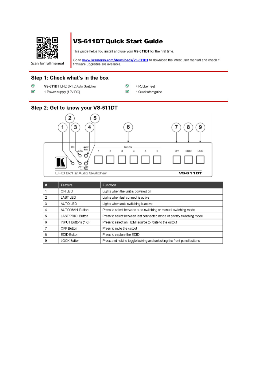
3.2 Defining the VS-611DT UHD 6x1:2 Auto Switcher 6
4 Connecting the VS-611DT 8
4.1 Connecting a Serial Controller to the VS-611DT via RS-232 9
5 Operating the VS-611DT 10
5.1 Switching – Manual and Auto 10
5.2 Performing a Factory Reset 11
5.3 Locking the Front Panel Buttons 12
5.4 Turning the Output Off 12
5.5 Copying the EDID 12
5.6 Setting the 5V Output Time Delay 13
5.7 Setting HDCP Capability 13
5.8 Setting the Audio Output 14
5.9 Setting the Switching Speed 15
5.10 Using VCOM on USB 15
5.11 Upgrading the Firmware 16
5.12 Step-In Support 16
5.13 Controlling the VS-611DT via the Terminal Block Connector 16
6 Using the Web Pages 17
6.1 Routing Inputs to Outputs 17
6.2 Using EDID Settings 19
6.3 Setting Device ID Parameters 21
6.4 Contacting Kramer 22
7 Technical Specifications 23
8 Supported Resolutions 24
9 Default Settings 26
9.1 Default Communication Settings 26
9.2 First Power On Default Settings 26
9.3 Default EDID 27
10 Protocol 3000 29
10.1 Understanding Protocol 3000 30
10.2 Kramer Protocol 3000 Syntax 31
10.3 Protocol 3000 Commands 33
Figures
Figure 1: VS-611DT UHD 6x1:2 Auto Switcher 6
Figure 2: Connecting the VS-611DT UHD 6x1:2 Auto Switcher 9
Figure 3: Connecting the Contact Closure Remote Control Pins 16
VS-611DT – Contents i
Page 6

1 Introduction
Welcome to Kramer Electronics! Since 1981, Kramer Electronics has been
providing a world of unique, creative, and affordable solutions to the vast range of
problems that confront video, audio, presentation, and broadcasting professionals
on a daily basis. In recent years, we have redesigned and upgraded most of our
line, making the best even better!
Our 1,000-plus different models now appear in 14 groups that are clearly defined by
function: GROUP 1: Distribution Amplifiers; GROUP 2: Switchers and Routers;
GROUP 3: Control Systems; GROUP 4: Format/Standards Converters; GROUP 5:
Range Extenders and Repeaters; GROUP 6: Specialty AV Products; GROUP 7:
Scan Converters and Scalers; GROUP 8: Cables and Connectors; GROUP 9:
Room Connectivity; GROUP 10: Accessories and Rack Adapters; GROUP 11:
Sierra Video Products; GROUP 12: Digital Signage; GROUP 13: Audio; and
GROUP 14: Collaboration.
Congratulations on purchasing your Kramer VS-611DT UHD 6x1:2 Auto Switcher,
which is ideal for the following typical applications:
• Education
• Corporate
• Any other AV installation that requires selecting and switching between several
HDMI sources automatically
VS-611DT – Introduction 1
Page 7

Go to www.kramerav.com/manual/VS-611DT to check for up-to-date user
Caution:
There are no operator serviceable parts inside the unit.
provided with the unit.
before installing.
2 Getting Started
We recommend that you:
• Unpack the equipment carefully and save the original box and packaging
materials for possible future shipment
• Review the contents of this user manual
manuals, application programs, and to check if firmware upgrades are
available (where appropriate).
2.1 Achieving the Best Performance
To achieve the best performance:
• For optimum range and performance, use the recommended Kramer cables
available at www.kramerav.com/product/VS-611DT
• Do not secure the cables in tight bundles or roll the slack into tight coils.
• Avoid interference from neighbouring electrical appliances that may adversely
influence signal quality.
• Position your VS-611DT away from moisture, excessive sunlight and dust.
This equipment is to be used only inside a building. It may only be
connected to other equipment that is installed inside a building.
2.2 Safety Instructions
Warning:
Warning:
2 VS-611DT - Getting Started
Use only the Kramer Electronics power supply that is
Disconnect the power and unplug the unit from the wall
Page 8

2.3 Recycling Kramer Products
The Waste Electrical and Electronic Equipment (WEEE) Directive 2002/96/EC aims
to reduce the amount of WEEE sent for disposal to landfill or incineration by
requiring it to be collected and recycled. To comply with the WEEE Directive,
Kramer Electronics has made arrangements with the European Advanced
Recycling Network (EARN) and will cover any costs of treatment, recycling and
recovery of waste Kramer Electronics branded equipment on arrival at the EARN
facility. For details of Kramer’s recycling arrangements in your particular country go
to our recycling pages at www.kramerav.com/support/recycling/
.
VS-611DT – Getting Started 3
Page 9

3 Overview
The VS-611DT is a high-performance automatic switcher for HDMI video signals
with resolution up to 4K@60 UHD (4:2:0). With six HDMI inputs, the unit can
automatically or manually switch to a predefined or last connected input whenever
the currently active video signal is interrupted or whenever a higher-priority video
signal is introduced. The output signal is distributed to HDBaseT and HDMI (4K)
outputs.
The VS-611DT features:
• A maximum data rate of up to 8.91Gbps (2.97Gbps per graphic channel)
• Extended Range (100m) of HDBaseT 4K@60Hz (4:2:0)
• HDTV compatible
• HDCP and HDMI compliant
• Six HDMI inputs and HDBT and HDMI outputs (DA)
• HDMI support for Deep Color, Ethernet, ARC, up to 7.1 audio channels
• HDMI ARC de-embedding from output to balanced stereo audio line out
uncompressed
• Step-in support
• Automatic input detection and selection
• Auto-power off when no HDMI input for 30 seconds (selectable)
• HDCP on/off switching
• EDID configuration options
• Selectable switching – manual or fast auto switching according to last
connected or preset priority
• Full HDBaseT certification (including bidirectional RS-232, Ethernet, IR and
POE)
• POE source for HDBaseT receiver (that is PoE compliant)
• Contact closure for remote manual switching override
• Firmware upgrade over mini-USB, RS-232, RJ-45
4 VS-611DT - Overview
Page 10

• Varied control options – front panel keyboard, HDBaseT(local and through
HDBaseT), Ethernet, RS-232 (local and through remote HDBaseT source with
K-Link support), IR (local and through HDBaseT)
• Built-in Web server
• Support for Protocol 3000 and K-Upload
3.1 About Fast Switching
Older display devices required a longer time between the loss of one digital signal
and the introduction of another, as well as a physical disconnection of the
interconnecting cable in order to be able to detect and adjust to the new video
attributes and parameters. Normal switching, therefore, introduced a 5V signal
disconnection along with a delay in switching. Many newer display devices,
however, are now capable of “on-the-fly” switching.
Depending on the display device in use, the VS-611DT allows for fast switching
(minor reset and the connection kept alive) and extra fast switching (no reset and
the connection kept alive). Using the fast switching mode allows for fraction-of-a-
second switching times when using high performance display devices or when
using a scaler on the video output.
VS-611DT – Overview 5
Page 11
#
Feature
Function
1
ON LED
Lights when the unit is powered on
2
LAST LED
Lights when in Last Connected mode
3
AUTO LED
Lights when in Auto Switching mode
switching mode (see Section 5.1)
priority switching mode (see Section 5.1)
Off: the input signal is not active and not selected
7
Button
Press to disconnect the output mode (see
Section 5.4)
8
EDID Button
Press to capture the EDID (see Section 5.5)
9
LOCK Button
Press and hold to toggle locking and unlocking the
front panel buttons (see Section 5.3)
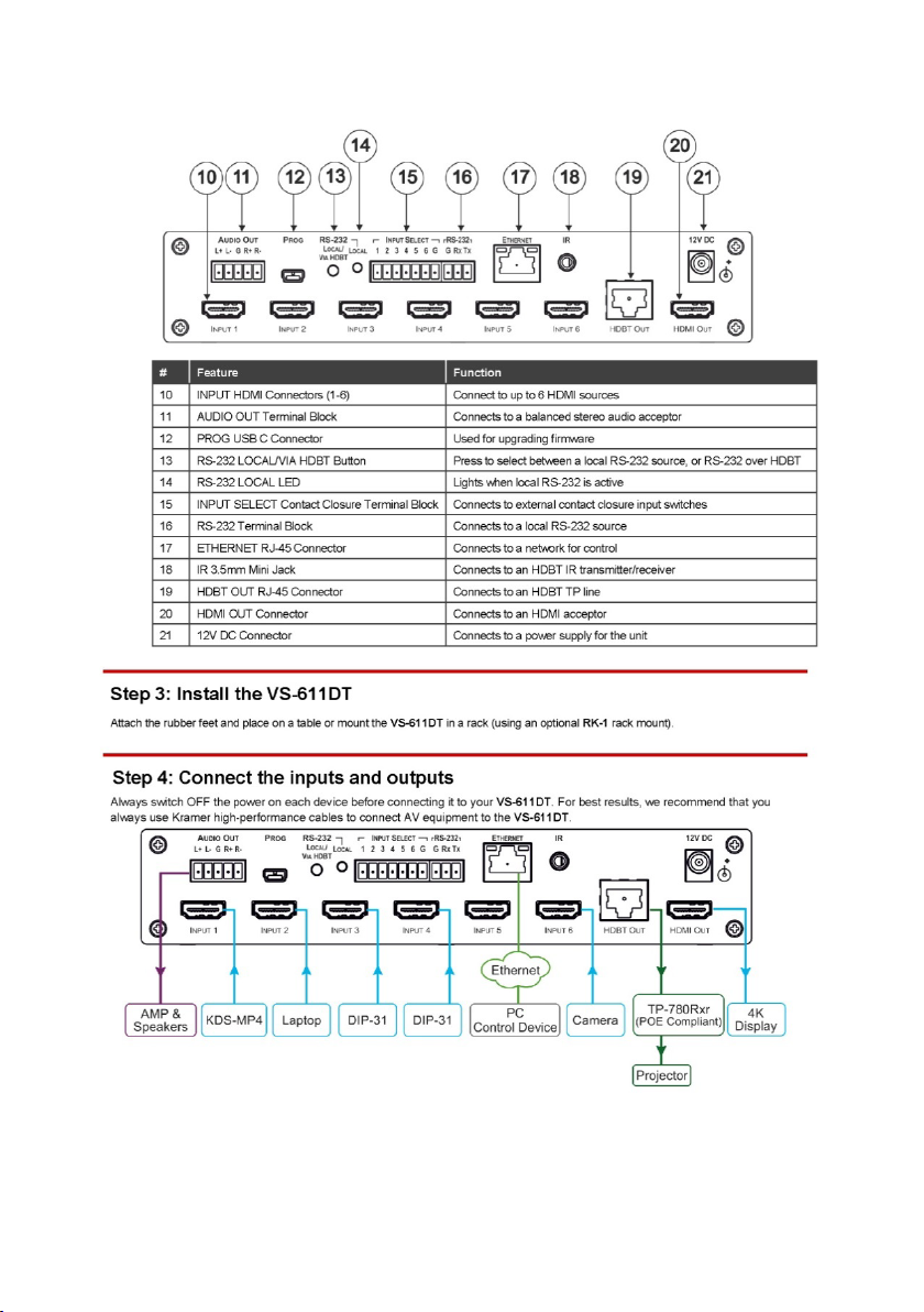
10
INPUT HDMI Connectors (1-
Connect to up to 6 HDMI sources
11
AUDIO OUT Terminal Bl ock
Connects to a balanced stereo audio acceptor
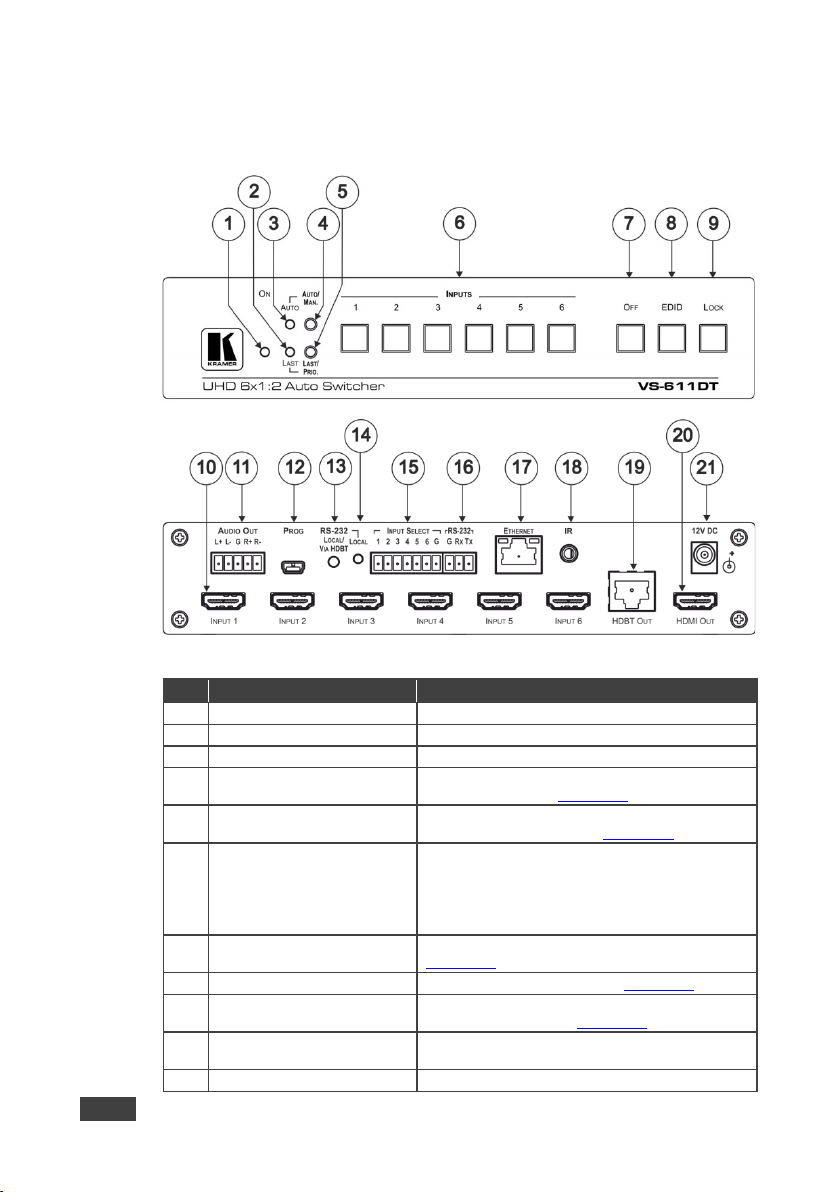
3.2 Defining the VS-611DT UHD 6x1:2 Auto Switcher
This section defines the VS-611DT.
Figure 1: VS-611DT UHD 6x1:2 Auto Switcher
4 AUTO/MAN. Button Press to select between auto-switching or manual
5 LAST/PRIO. Button Press to select between last connected mode or
6 INPUT Buttons (1-6) Press to select an HDMI source to route to the
OFF
6)
6 VS-611DT - Overview
output. The LEDs indicate:
Lit: the input is selected
Dim: the input signal is active but not selected
Page 12

#
Feature
Function
12
PROG USB Mini-B Connector
Used for upgrading firmware (see Section 5.10)
13
RS-232 LOCAL/VIA HDBT
Button
Press to select between a local RS-232 source, or
RS-232 over HDBT
14
RS-232 LOCAL LED
Lights when local RS-232 is active
15
INPUT SELECT Contact
Connects to external contact closure input switches
Section 4.1)
17
ETHERNET RJ-45 Connector
Connects to a network for control
18
IR 3.5mm Mini Jack
Connects to an HDBT IR transmitter
19
HDBT OUT RJ-45 Connector
Connects to an HDBT TP line
20
HDMI OUT Connector
Connects to an HDMI acceptor
21
12V DC Connector
Connects to a power supply for the unit
Closure Terminal Block
16 RS-232 Terminal Block Connects to a local RS-232 source (see
(see Section 5.13)
VS-611DT – Overview 7
Page 13

and then switch on the power to each device.
4 Connecting the VS-611DT
Always switch off the power to each device before connecting it to
your VS-611DT. After connecting your VS-611DT, connect its power
You do not have to connect all the inputs and outputs, connect only
those that are required.
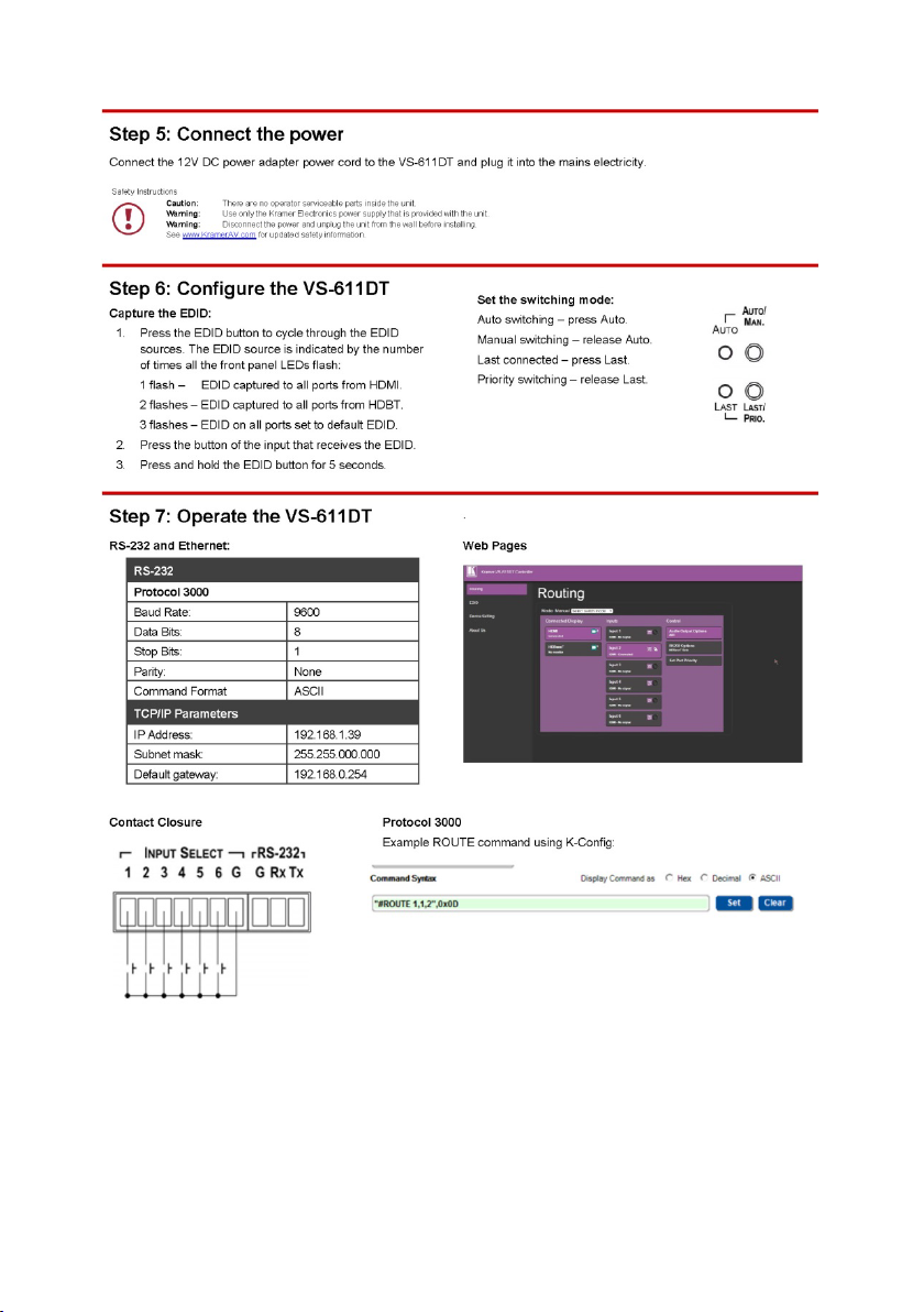
To connect the VS-611DT as illustrated in the example in Figure 2
1. Connect up to six HDMI sources (for example, KDS-MP4(s), laptop(s),
DIP-31(s)) to INPUTs 1-6 using HDMI cables.
2. Connect the HDBT OUT RJ-45 connector to an HDBaseT acceptor (for
example, a TP-780Rxr HDBaseT receiver or an HDBaseT projector) using
an HDBT twisted pair cable.
3. Connect the HDMI OUT connector to an HDMI acceptor (for example, a 4K
display) using an HDMI cable.
4. Connect the AUDIO OUT terminal block (line out) to a balanced audio
acceptor (for example, a power amplifier with speakers) using an audio
cable.
5. If needed for control, connect the ETHERNET RJ-45 and/or the RS-232
terminal block ports to a network or a serial control device.
6. If needed, connect the INPUT SELECT terminal block to up to six contact
closure switches.
7. If needed, connect an HDBT IR transmitter to the IR 3.5mm mini jack.
:
8 VS-611DT - Connecting the VS-611DT
Page 14
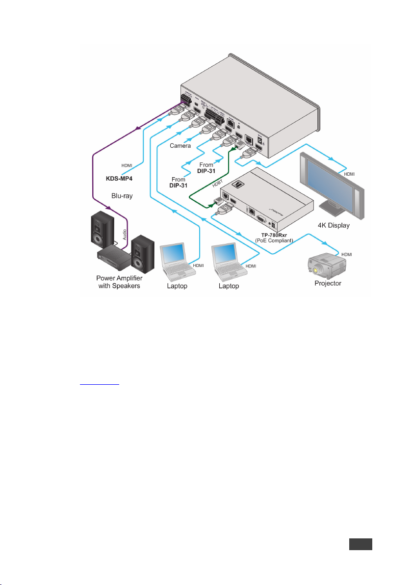
Figure 2: Connecting the VS-611DT UHD 6x1:2 Auto Switcher
4.1 Connecting a Serial Controller to the VS-611DT via RS-232
The VS-611DT operates at 9600 baud rate (see all communication parameters in
Section 9.1
To connect a serial controller to the VS-611DT:
• From the RS-232 9-pin D-sub serial port on the serial controller connect:
VS-611DT – Connecting the VS-611DT 9
).
Pin 2 to the TX pin on the VS-611DT RS-232 terminal block.
Pin 3 to the RX pin on the VS-611DT RS-232 terminal block.
Pin 5 to the GND pin on the VS-611DT RS-232 terminal block.
Page 15

5 Operating the VS-611DT
This section describes how to operate the VS-611DT.
5.1 Switching – Manual and Auto
Switching can be performed automatically or manually using the device’s keypad,
Web pages (see Section 6.1), or control commands (see Section 10.3.2
section describes using the keypad buttons to select Auto or Manual switch modes.
5.1.1 Manual Switch Mode
In Manual switch mode, the VS-611DT does not automatically switch to another
channel even if an input signal is not detected on the manual input.
To select the manual switch mode:
1. Press the Auto/Man. button to turn the Auto/Man. LED off.
2. Press any of the Input 1-6 buttons to switch the input.
The keys respond as follows:
). This
Input LED bright: input active and selected
Input LED dim: input active and not selected
Input LED off: input is not active and not selected
5.1.2 Auto Switch Mode
In Auto switch mode, the VS-611DT automatically switches one of six HDMI inputs
to a predefined or the last connected input whenever the currently active video
signal is interrupted or whenever a higher-priority video signal is detected.
10 VS-611DT - Operating the VS-611DT
Page 16

To select the auto switch mode:
1. Press the Auto/Man button to turn the Auto LED on.
2. Press the Last/Prio button to select an auto switch mode:
Last connected (Last LED on) – The device always switches to a newly
detected active video source. When the device is powered on, the
output switches to the highest priority input.
Priority (Last LED off) – The device always switches to the highest
priority input source. The default priority is Input 1 then Input 2.
5.1.3 Manual Override Mode
Auto switch mode can be overridden by a manual command, such as pressing an
input button or sending a control command. In such a case, the system switches to
the manually selected source. If this manually selected source is not active, the
system waits a set amount of time (10 seconds, default, adjustable on the Web
page) and then switches back to Auto mode. Manual override selection is not stored
in non-volatile memory.
A step-in command is considered a manual switching command.
5.2 Performing a Factory Reset
Factory reset returns all the parameters of the device to their factory default
settings.
To perform a factory reset:
1. Disconnect device power.
2. Press and hold Input 1 while reconnecting device power.
All indicators flash while resetting to the factory default parameters. When all
the lights turn off the reset is complete.
VS-611DT – Operating the VS-611DT 11
Page 17

5.3 Locking the Front Panel Buttons
Lock the front panel buttons to prevent tampering.
• Press and hold Lock until the button lights.
The front panel buttons are locked.
• Press and hold Lock until the button goes off.
The front panel buttons are unlocked.
5.4 Turning the Output Off
• Press the Off button to turn off the outputs.
Both HDMI and HDBaseT outputs turn off.
5.5 Copying the EDID
The EDID is a data structure transmitted by the display that enables the VS-611DT
to recognize the display connected to the output. The VS-611DT acquires and
stores the EDID to make reconnection to the display effortless.
You can acquire the EDID from the:
• HDMI output to the selected inputs.
• HDBaseT output to the selected inputs.
• Default EDID to the selected inputs (for the default EDID, see Section 9.3
Pressing the front panel EDID button captures the EDID either from the HDMI
output port or from the HDBaseT output port to all inputs according to the following
scenario:
To copy the EDID from the HDMI output:
1. Press the EDID button to cycle through the EDID sources until all front panel
LEDs flash once, indicating that the EDID is copied from HDMI.
2. Press the button of the input that receives the EDID.
3. Press and hold EDID for 5 seconds to copy.
12 VS-611DT - Operating the VS-611DT
).
Page 18

To copy the EDID from the HDBT output:
1. Press the EDID button to cycle through the EDID sources until all front panel
LEDs flash twice, indicating that the EDID is copied from HDBT.
2. Press the button of the input that receives the EDID.
3. Press and hold EDID for 5 seconds to copy.
To copy the default EDID:
1. Press the EDID button to cycle through the EDID sources until all front panel
LEDs flash three times, indicating that the default EDID is copied
2. Press the button of the input that receives the EDID.
3. Press EDID and hold for 5 sec to copy.
5.6 Setting the 5V Output Time Delay
When there is no signal clock or 5V input on all inputs for 15 minutes, the device
shuts down the 5V output. This enables output devices such as projectors or
displays to go to sleep. The 15 minute default time delay can be changed to 5
minutes or 10 minutes using the Auto Sync Off feature on the Device Settings Web
page (see Section 6.3
).
5.7 Setting HDCP Capability
Each input can be individually set to HDCP support on or off.
To set HDCP support:
1. Disconnect device power.
2. Press and hold the Lock button while reconnecting device power.
The Lock LED flashes indicating HDCP setup mode.
3. Press the Input 1-6 button(s) to set HDCP.
4. If the LED is on, HDCP passes to the port.
If flashing, HDCP does not.
VS-611DT – Operating the VS-611DT 13
Page 19

the analog output produce noise.
5. Press the Lock button to confirm the choice or the Off button to quit.
If no button is pressed, the mode quits after 10 seconds.
5.8 Setting the Audio Output
The audio output can be set to ARC or de-embedded audio output.
When inputting ARC or HDMI multi-channel LPCM audio, the analog
outputs the front right and front left components. If the device is in
ARC mode and compressed audio is input, speakers connected to
14 VS-611DT - Operating the VS-611DT
Page 20

To set the audio output:
1. Press and hold the Off + Input 3 buttons.
The Lock and Input 3 LEDs flash.
2. Press the Input 3 button to set ARC/de-embedding audio:
ARC audio out – Flashing LED 3
De-embedding audio out – Solid LED 3
5.9 Setting the Switching Speed
The VS-611DT supports setting normal and fast (default) switching speeds.
To set switching speed modes:
1. Disconnect device power.
2. Press and hold one of the following buttons together with the OFF button:
IN 1 button – for setting fast switching speed mode.
IN 2 button – for setting normal switching speed mode.
3. Power the device on.
The device switching speed is modified.
Switching speed can also be set using the Routing Web page (see Section 6.1
).
5.10 Using VCOM on USB
The device’s USB port can work as a virtual COM (VCOM) port. Verify that the USB
port on the PC that connects to the VS-611DT is configured as a VCOM port. You
may need to install a driver to do this. Use a tool such as Hercules or K-Config to
use P3K over USB. For more information on using the commands see Section 10
VS-611DT – Operating the VS-611DT 15
.
Page 21

5.11 Upgrading the Firmware
The VS-611DT can be upgraded via USB or RS-232.
For instructions on upgrading the firmware, see “K-Upload Software User Guide”
(www.kramerav.com/support/download.asp?f=39700
).
5.12 Step-In Support
The VS-611DT supports programmable step-in functionality when used in
conjunction with compatible step-in devices, such as the SID-X3N and DIP-31
(using an HDMI cable that supports HEC, the HDMI Ethernet Channel).
When ARC mode is enabled, Input 1 step-in mode is disabled. If you require step-in
mode on Input 1, set the audio output to the device inputs (see Section 6.1
5.13 Controlling the VS-611DT via the Terminal Block Connector
The INPUT SELECT terminal block connector includes six input pins and a G pin
for selecting an input.
).
The contact closure remote control pins operate in a similar way to the input buttons
(see Section 5.1.1
to-make momentary contact) you can select any of the inputs. To do so,
momentarily connect the required input pin (1 to 6) to the G (ground) pin of the
INPUT SELECT terminal block connector, as
). Using the contact closure remote control (also known as push-
Figure 3 illustrates.
Do not connect more than one input pin to the G pin at the same time.
Figure 3: Connecting the Contact Closure Remote Control Pins
16 VS-611DT - Operating the VS-611DT
Page 22

6 Using the Web Pages
Use the Web page to control the device: switch the input, set the switch mode, set
the ARC link, import HDCP and more.
To access the Web page:
• Enter the IP address (192.168.1.39) in the browser.
The Router window opens.
6.1 Routing Inputs to Outputs
• On the left side, click the Routing tab.
The Routing window opens:
VS-611DT – Using the Web Pages 17
Page 23

Feature
Function
Mode Dropdown
Click to select Manual, Priority or Last
Fast Switching Checkbox
Click to select/de-select fast switching
Connected Display
Click to select HDMI or HDBaseT
Click small insert box to mute/un-mute video
Inputs (1 through 6)
Click to select Input 1 through Input 6
Control – Audio Output Options
Click to select Input HDMI Audio or ARC
Control – RS-232 Options
Click to select Local RS-232 or HDBaseT Data
Set Port Priority
Click to open the priority selector. Click the Set dropdown
and choose a numerical priority for the port (1 to 6)
Click HDCP insert box to select/de-select HDCP
Click Remote insert box to set remote device settings
To select a switching mode:
1. Click the Select switching mode dropdown.
2. Choose from Manual, Priority and Last.
To set port priority:
1. Click Set Port Priority.
The Set Port Priority window opens.
2. Click the Set dropdown for the desired port.
3. Set a priority from 1 to 6.
4. Click OK to set.
18 VS-611DT - Using the Web Pages
Page 24

Feature
Function
Click to select the
, or the
monitor or HDBaseT monitor)
File Browse
Click to open a window that allows you to browse and
select an EDID saved to the computer disk
Inputs Capability
Click to select/deselect:
2-Channel LPCM only
Short Summary
Describes the characteristics of the EDID source device
6.2 Using EDID Settings
• On the left side, click the EDID tab.
The EDID window opens:
Read From
Copy To Click the Inputs checkbox to select/de-select all input
VS-611DT – Using the Web Pages 19
Default EDID
RGB color space only
Deep color Off
devices
Click each input to which to copy the chosen EDID
Outputs (HDMI
Page 25

shown in the following illustration, allow the browser to upload the file
To copy EDID data from an output or an EDID file to inputs:
1. Click the source button (output) from which to copy the EDID. The button
changes color and the EDID summary shows the EDID data.
2. To copy an EDID file, click the source Browse button. The Windows Browser
opens.
3. Browse to the required file.
4. Select the required file and click Open.
5. Click the input capability checkbox.
6. When Set Color Space selected, the EDID color space is set to RGB only
when copying the EDID.
7. When Set Deep Color selected, the EDID deep color is set to 24-bits only
when copying the EDID.
8. Click one or more destination inputs, or select all inputs by checking the
Inputs check-box. All selected input buttons change color and the EDID
summary information reflects the input selection(s).
9. Click the Copy button. The “EDID was copied” success message is
displayed and EDID data is copied to the selected input(s).
10. Click OK.
When selecting the EDID file, if the path indicates \fakepath\ as
in the browse Tool/Internet. Safari does not support file upload.
20 VS-611DT - Using the Web Pages
Page 26

6.3 Setting Device ID Parameters
The Device Settings page enables you modify some communication parameters
and view others.
To modify serial or Ethernet communication parameters:
1. Adjust the parameters as required, either by entering the parameters
directly or by using the drop-down list.
2. Click Set. The changes are saved.
3. Re-power the device.
VS-611DT – Using the Web Pages 21
Page 27

6.4 Contacting Kramer
The About Us screen displays the version of the Web software, Kramer’s address,
phone, email and Web site.
22 VS-611DT - Using the Web Pages
Page 28

INPUTS:
6 HDMI connectors, 1 IR on a 3.5mm mini-jack
OUTPUTS:
1 HDMI connector, 1 HDBaseT on an RJ-45 connector, 1 balanced
PORTS:
1 Ethernet on an RJ-45 connector, 1 RS-232 connector on a 3-pin
MAX. DATA RATE:
9Gbps (3Gbps per graphic channel) with 4K support
STANDARD:
OUTPUT RESOLUTIONS:
Up to UXGA, 4K x 2K, 4K@60Hz (4:2:0)
CONTROLS:
Front panel keyboard, HDBaseT Ethernet, RS-232, IR, contact
closure
SOFTWARE SUPPORT:
Protocol 3000, K-Router Plus, EDID Designer, K-Upload
OPERATING TEMPERATURE:
0° to +40°C (32° to 104°F)
STORAGE TEMPERATURE:
-40° to +70°C (-40° to 158°F)
HUMIDITY:
10% to 90%, RHL non-condensing
POWER CONSUMPTION:
12V DC, 2.8A
DIMENSIONS:
21.5cm x 16.3cm x 4.4cm (8.5” x 6.4” x 1.7”) W, D, H (1/2 19” 1U)
WEIGHT:
0.95kg (2.1lbs) approx.
SHIPPING DIMENSIONS:
35.1cm x 21.2cm x 7.2cm (13.8” x 8.4” x 2.8”) W , D, H
SHIPPING W EIGHT:
1.58kg (3.5lbs)
INCLUDED ACCESSORIES:
Power cord
7 Technical Specifications
stereo audio on a 5-pin terminal block
terminal block, 6 contact closures on a 7-pin terminal block, 1 USB
mini-B connector for firmware upgrading
COMPLIANCE WITH HD MI
Specifications are subject to change without notice
For the most updated resolution list, go to our W eb site at www.kramerav.com
Deep Color, Ethernet, ARC, up to 7.1 Audio Channels, CEC
VS-611DT – Technical Specifications 23
Page 29

VIC
Number
Resolution
0
No Signal (for input) / Native – EDID (for output)
1
640x480p @59.94Hz/60Hz
2
720x480p @59.94Hz/60Hz
3
720x480p @59.94Hz/60Hz
4
1280x720p @59.94Hz/60Hz
5
1920x1080i @59.94Hz/60Hz
6
720(1440)x480i @59.94Hz/60Hz
7
720(1440)x480i @59.94Hz/60Hz
8
720(1440)x240p @59.94Hz/60Hz
9
720(1440)x240p @59.94Hz/60Hz
10
2880x480i @59.94Hz/60Hz
11
2880x480i @59.94Hz/60Hz
12
2880x240p @59.94Hz/60Hz
13
2880x240p @59.94Hz/60Hz
14
1440x480p @59.94Hz/60Hz
15
1440x480p @59.94Hz/60Hz
16
1920x1080p @59.94Hz/60Hz
17
720x576p @50Hz
18
720x576p @50Hz
19
1280x720p @50Hz
20
1920x1080i @50Hz
21
720(1440)x576i @50Hz
22
720(1440)x576i @50Hz
23
720(1440)x288p @50Hz
24
720(1440)x288p @50Hz
25
2880x576i @50Hz
26
2880x576i @50Hz
27
2880x288p @50Hz
28
2880x288p @50Hz
29
1440x576p @50Hz
30
1440x576p @50Hz
31
1920x1080p @50Hz
32
1920x1080p @23.97Hz/24Hz
33
1920x1080p @25Hz
34
1920x1080p @29.97Hz/30Hz
35
2880x480p @59.94Hz/60Hz
36
2880x480p @59.94Hz/60Hz
37
2880x576p @50Hz
38
2880x576p @50Hz
39
1920x1080i @50Hz
40
1920x1080i @100Hz
8 Supported Resolutions
24 VS-611DT - Supported R esolutions
Page 30

VIC
Number
Resolution
41
1280x720p @100H z
42
720x576p @100H z
43
720x576p @100H z
44
720(1440)x576i @100Hz
45
720(1440)x576i @100Hz
46
1920x1080i @119.88/120Hz
47
1280x720p @119.88/120Hz
48
720x480p @119.88/120Hz
49
720x480p @119.88/120Hz
50
720(1440)x480i @119.88/120Hz
51
720(1440)x480i @119.88/120Hz
52
720x576p @200H z
53
720x576p @200H z
54
720(1440)x576i @200Hz
55
720(1440)x576i @200Hz
56
720x480p @239.76/240Hz
57
720x480p @239.76/240Hz
58
720(1440)x480i @239.76/240Hz
59
720(1440)x480i @239.76/240Hz
60
1280x720p @23.97Hz/24Hz
61
1280x720p @25Hz
62
1280x720p @29.97Hz/30Hz
63
1920x1080p @119.88/120Hz
64
1920x1080p @100Hz
VS-611DT – Supported Resolutions 25
Page 31

RS-232
Protocol 3000 (Default)
Baud Rate
9600
Data Bits
8
Stop Bits
1
Parity
None
Command Format
ASCII
Parameter
Value
Out HDCP mode
Follow
Communication Format
KMR3000 (KMR device)
Close Output 5v Time
30sec
Current Input Source Port
Input port 1
Manual/Auto Switch Mode
Auto mode
Pr/Lc Switch Mode
Priority mode
ARC/De-embed Audio Out
De-embed audio out
RS-232 Connection
CPU
Input Port HDCP
All ON
Kramer 3000 Model Name
‘V', 'S', '-', '6', '1', '1', 'D', 'T'
EDID
Default
USB for Virtual Com
Virtual Com
IP Address
192.168.1.39
Mask Number
255.255.0.0
Gateway Number
192.168.0.254
DHCP
Disabled (OFF)
9 Default Settings
The VS-611DT has the following default settings for communication, first power on
and EDID.
9.1 Default Communication Settings
9.2 First Power On Default Settings
26 VS-611DT - Default Settings
Page 32

9.3 Default EDID
Model name............... VS-611DT
Manufacturer............. KMR
Plug and Play ID......... KMR03ED
Serial number............ 1
Manufacture date......... 2014, ISO week 15
Filter driver............ None
-------------------------
EDID revision............ 1.3
Input signal type........ Digital (HDMI-a)
Color bit depth.......... Undefined
Display type............. RGB color
Screen size.............. 700 x 390 mm (31.5 in)
Power management......... Not supported
Extension blocs.......... 1 (CEA-EXT)
-------------------------
DDC/CI................... Not supported
Color characteristics
Default color space...... Non-sRGB
Display gamma............ 2.20
Red chromaticity......... Rx 0.640 - Ry 0.341
Green chromaticity....... Gx 0.286 - Gy 0.610
Blue chromaticity........ Bx 0.146 - By 0.069
White point (default).... Wx 0.284 - Wy 0.293
Additional descriptors... None
Timing characteristics
Horizontal scan range.... 31-94kHz
Vertical scan range...... 50-85Hz
Video bandwidth.......... 170MHz
CVT standard............. Not supported
GTF standard............. Not supported
Additional descriptors... None
Preferred timing......... Yes
Native/preferred timing.. 1280x720p at 60Hz
Modeline............... "1280x720" 74.250 1280 1390 1430 1650 720 725 730 750 +hsync +vsync
Detailed timing #1....... 1920x1080p at 60Hz (16:9)
Modeline............... "1920x1080" 148.500 1920 2008 2052 2200 1080 1084 1089 1125 +hsync +vsync
Standard timings supported
720 x 400p at 70Hz - IBM VGA
720 x 400p at 88Hz - IBM XGA2
640 x 480p at 60Hz - IBM VGA
640 x 480p at 67Hz - Apple Mac II
640 x 480p at 72Hz - VESA
640 x 480p at 75Hz - VESA
800 x 600p at 56Hz - VESA
800 x 600p at 60Hz - VESA
800 x 600p at 72Hz - VESA
800 x 600p at 75Hz - VESA
832 x 624p at 75Hz - Apple Mac II
1024 x 768i at 87Hz - IBM
1024 x 768p at 60Hz - VESA
1024 x 768p at 70Hz - VESA
1024 x 768p at 75Hz - VESA
1280 x 1024p at 75Hz - VESA
1152 x 870p at 75Hz - Apple Mac II
1280 x 720p at 60Hz - VESA STD
1280 x 800p at 60Hz - VESA STD
1440 x 900p at 60Hz - VESA STD
1280 x 960p at 60Hz - VESA STD
1280 x 1024p at 60Hz - VESA STD
1400 x 1050p at 60Hz - VESA STD
1680 x 1050p at 60Hz - VESA STD
1600 x 1200p at 60Hz - VESA STD
EIA/CEA-861 Information
Revision number.......... 3
VS-611DT – Default Settings 27
Page 33

IT underscan............. Not supported
Basic audio.............. Supported
YCbCr 4:4:4.............. Not supported
YCbCr 4:2:2.............. Not supported
Native formats........... 1
Detailed timing #1....... 720x480p at 60Hz (4:3)
Modeline............... "720x480" 27.000 720 736 798 858 480 489 495 525 -hsync -vsync
Detailed timing #2....... 1920x1080i at 60Hz (16:9)
Modeline............... "1920x1080" 74.250 1920 2008 2052 2200 1080 1084 1094 1124 interlace +hsync +vsync
Detailed timing #3....... 1920x1080i at 50Hz (16:9)
Modeline............... "1920x1080" 74.250 1920 2448 2492 2640 1080 1084 1094 1124 interlace +hsync +vsync
Detailed timing #4....... 1280x720p at 60Hz (16:9)
Modeline............... "1280x720" 74.250 1280 1390 1430 1650 720 725 730 750 +hsync +vsync
Detailed timing #5....... 1280x720p at 50Hz (16:9)
Modeline............... "1280x720" 74.250 1280 1720 1760 1980 720 725 730 750 +hsync +vsync
CE video identifiers (VICs) - timing/formats supported
720 x 576p at 50Hz - EDTV (4:3, 16:15)
1280 x 720p at 50Hz - HDTV (16:9, 1:1)
1920 x 1080i at 60Hz - HDTV (16:9, 1:1)
1920 x 1080i at 50Hz - HDTV (16:9, 1:1)
1280 x 720p at 60Hz - HDTV (16:9, 1:1) [Native]
1920 x 1080p at 60Hz - HDTV (16:9, 1:1)
1920 x 1080p at 50Hz - HDTV (16:9, 1:1)
NB: NTSC refresh rate = (Hz*1000)/1001
CE audio data (formats supported)
LPCM 2-channel, 24-bits at 44/48 kHz
CE speaker allocation data
Channel configuration.... 2.0
Front left/right......... Yes
Front LFE................ No
Front center............. No
Rear left/right.......... No
Rear center.............. No
Front left/right center.. No
Rear left/right center... No
Rear LFE................. No
CE vendor specific data (VSDB)
IEEE registration number. 0x000C03
CEC physical address..... 1.0.0.0
Maximum TMDS clock....... 165MHz
Report information
Date generated........... 03/11/2015
Software revision........ 2.60.0.972
Data source.............. Real-time 0x0042
Operating system......... 6.1.7601.2.Service Pack 1
Raw data
00,FF,FF,FF,FF,FF,FF,00,2D,B2,ED,03,01,00,00,00,0F,18,01,03,82,46,27,78,0A,D5,7C,A3,57,49,9C,25,
11,48,4B,FF,FF,80,81,C0,81,00,95,00,81,40,81,80,90,40,B3,00,A9,40,01,1D,00,72,51,D0,1E,20,6E,28,
55,00,7E,88,42,00,00,1E,02,3A,80,18,71,38,2D,40,58,2C,45,00,C4,8E,21,00,00,1E,00,00,00,FC,00,56,
53,2D,36,31,31,44,54,0A,20,20,20,20,00,00,00,FD,00,32,55,1F,5E,11,00,0A,20,20,20,20,20,20,01,B1,
02,03,1A,41,47,11,13,05,14,84,10,1F,23,09,06,04,83,01,00,00,65,03,0C,00,10,00,8C,0A,D0,8A,20,E0,
2D,10,10,3E,96,00,58,C2,21,00,00,18,01,1D,80,18,71,1C,16,20,58,2C,25,00,C4,8E,21,00,00,9E,01,1D,
80,D0,72,1C,16,20,10,2C,25,80,C4,8E,21,00,00,9E,01,1D,00,72,51,D0,1E,20,6E,28,55,00,C4,8E,21,00,
00,1E,01,1D,00,BC,52,D0,1E,20,B8,28,55,40,C4,8E,21,00,00,1E,00,00,00,00,00,00,00,00,00,00,00,C5
28 VS-611DT - Default Settings
Page 34

10 Protocol 3000
The VS-611DT can be operated using the Kramer Protocol 3000 serial commands.
The command framing varies according to how you interface with the VS-611DT. In
the following example, a basic video input switching command that routes a layer 1
video signal to HDBT out 1 from HDMI input 2 (ROUTE 1,1,2), is entered as
follows:
• Terminal communication software, such as Hercules:
The framing of the command varies according to the terminal
communication software.
• K-Touch Builder (Kramer software):
• K-Config (Kramer configuration software):
VS-611DT – Protocol 3000 29
Page 35

characters.
All the examples provided in this section are based on using the
K-Config software.
You can enter commands directly using terminal communication software (e.g.,
Hercules) by connecting a PC to the serial, Ethernet or the USB (VCOM) port on
the VS-611DT. To enter CR press the Enter key (LF is also sent but is ignored by
the command parser).
Commands sent from various non-Kramer controllers (e.g., Crestron) may require
special coding for some characters (such as, /X##). For more information, refer to
your controller’s documentation.
For more information about:
• Using Protocol 3000 commands, see Section 10.1
• General syntax used for Protocol 3000 commands, see Section 10.2
• Protocol 3000 commands available for the VS-611DT, see Section 10.3
10.1 Understanding Protocol 3000
Protocol 3000 commands are structured according to the following:
• Command – A sequence of ASCII letters (A-Z, a-z and -). A command and
its parameters must be separated by at least one space.
• Parameters – A sequence of alphanumeric ASCII characters (0-9, A-Z, a-z
and some special characters for specific commands). Parameters are
separated by commas.
• Message string – Every command entered as part of a message string begins
with a message starting character and ends with a message closing character.
A string can contain more than one command. Commands are
separated by a pipe (|) character. The maximum string length is 64
30 VS-611DT - Protocol 3000
Page 36

chain.
• Message starting character:
# – For host command/query
~ – For device response
• Device address – K-NET Device ID followed by @ (optional, K-NET only)
• Query sign – ? follows some commands to define a query request
• Message closing character:
CR – Carriage return for host messages (ASCII 13)
CR LF – Carriage return for device messages (ASCII 13) and line-feed
(ASCII 10)
• Command chain separator character – Multiple commands can be chained
in the same string. Each command is delimited by a pipe character (|). When
chaining commands, enter the message starting character and the message
closing character only at the beginning and end of the string.
Spaces between parameters or command terms are ignored.
Commands in the string do not execute until the closing character is
entered. A separate response is sent for every command in the
10.2 Kramer Protocol 3000 Syntax
The Kramer Protocol 3000 syntax uses the following delimiters:
• CR = Carriage return (ASCII 13 = 0x0D)
• LF = Line feed (ASCII 10 = 0x0A)
• SP = Space (ASCII 32 = 0x20)
Some commands have short name syntax in addition to long name syntax to enable
faster typing. The response is always in long syntax.
VS-611DT – Protocol 3000 31
Page 37

Start
Address (optional)
Body
Delimiter
#
Device_id@
Message
CR
Start
Body
Delimiter
#
Command SP
CR
Start
Address
Body
Delimiter
#
Device_id@
Command_1 Parameter1_1,Parameter1_2,…|
Parameter3_1,Parameter3_2,…|…
CR
Start
Address (optional)
Body
Delimiter
~
Device_id@
CR LF
Start
Address (optional)
Body
Delimiter
~
Device_id@
CR LF
The Protocol 3000 syntax is in the following format:
• Host Message Format:
• Simple Command – Command string with only one command without
addressing:
Parameter_1,Parameter_2,…
• Command String – Formal syntax with command concatenation and
addressing:
Command_2 Parameter2_1,Parameter2_2,…|
Command_3
• Device Message Format:
Message
• Device Long Response – Echoing command:
32 VS-611DT - Protocol 3000
Command SP [Param1,Param2 …] result
Page 38

#
Protocol handshaking
Syst em – mandatory
End User
BUILD-DATE
Get device build date
Syst em – mandatory
End User
FACTORY
Reset to factory default configuration
Syst em – mandatory
End User
HELP
Get command list
Syst em – mandatory
End User
IDV
Set visual indication from device
Syst em
End User
INFO-IO
Get in/out count
Syst em
End User
LOCK-FP
Set/get front panel lock
Syst em
Administrator
MODEL
Get device model
Syst em-mandatory
End User
NAME
Set/get machine (DNS) name
Syst em – Ethernet
Administrator
PROT-VER
Get device protocol version
Syst em – mandatory
End User
RESET
Reset device
Syst em – mandatory
Administrator
SIGNAL
Get input signal lock status
Syst em
End User
SN
Get device serial number
Syst em – mandatory
End User
VERSION
Get device firmware version
Syst em – mandatory
End User
10.3 Protocol 3000 Commands
This section lists and describes all the Protocol 3000 commands supported by the
VS-611DT.
• System Commands (see Section 10.3.1
)
• Switching/Routing Commands (see Section 10.3.2)
• Communication Commands (see Section 10.3.3)
• EDID Handling Commands (see Section 10.3.4)
10.3.1 System Commands
Command Description Type Permission
VS-611DT – Protocol 3000 33
Page 39

#
Set:
Protocol handshaking
#CR
~nn@SPOK CR LF
Validates the Protocol 3000 connection and gets the machine number
Step-in master products use this command to identify the availability of a device
“#”,0x0D
Set: - -
-
BUILD-DATE?
Set: - -
#BUILD-DATE?CR
~nn @BUILD-DATE SP
CR LF
– Format: hh:mm:ss where hh = hours, mm = minutes, ss = seconds
“#BUILD-DATE?”,0x0D
10.3.1.1 #
Functions Permission Transparency
Set:
Get:
Description Syntax
Get: - -
Response
Parameters
Response Triggers
Notes
K-Config Example
-
10.3.1.2 BUILD-DATE
Functions Permission Transparency
End User Public
- -
Get:
Description Syntax
Get: Get device build date
Response
dateSPtime
Parameters
date – Format: YYYY/MM/DD where YYYY = Year, MM = Month, DD = Day
time
Response Triggers
Notes
K-Config Example
34 VS-611DT - Protocol 3000
End User Public
Page 40

FACTORY
Get: - -
-
Reset device to factory default
configuration
~nn @FACTORY SPOK CR LF
“#FACTORY”,0x0D
Get:
HELP
End User
Public
1. #HELPCR
#HELPSP
~nn @HELPSP
:CR LF
CR LFUSAGE:
CR LF
HELPSP COMMAND_NAMECR LF
“#HELP”,0x0D
10.3.1.3 FACTORY
Functions Permission Transparency
Set:
Description Syntax
Set:
Get: - -
Response
Parameters
Response Triggers
Notes
This command deletes all user data from the device. The deletion can take some time.
Your device may require powering off and powering on for the changes to take effect.
K-Config Example
10.3.1.4 HELP
Functions Permission Transparency
Set: - - -
End User Public
#FACTORYCR
Description Syntax
Set: - -
Get:
Response
1. Multi-line: ~ nn@Device available protocol 3000 commands:CR LFcommand, SP
command...CR LF
2. Multi-line:
Parameters
COMMAND_NAME – name of a specific command
Response Triggers
Notes
To get help for a specific command use:
K-Config Example
VS-611DT – Protocol 3000 35
Get command list or help for specific
command
command
2.
description
COMMAND_NAMECR
usage
Page 41

IDV
Get: - -
-
#IDVCR
Get: - -
~nn @IDVSPOK CR LF
specific device from similar devices
“#IDV”,0x0D
Get:
INFO-IO?
End User
Public
Get:
Get in/out count
#INFO-IO?CR
~nn @INFO-IO? SPIN SP inputs_count,OUTSPoutputs_count CR LF
“#INFO-IO?”,0x0D
10.3.1.5 IDV
Functions Permission Transparency
Set:
Description Syntax
Set: Set visual indication from device
Response
Parameters
Response Triggers
Notes
Using this command, some devices can light a sequence of buttons or LEDs to allow identification of a
K-Config Example
10.3.1.6 INFO-IO
Functions Permission Transparency
Set: - - -
End User Public
Description Synta x
Set: - -
Response
Parameters
inputs_count – number of inputs in the unit
outputs_count – number of outputs in the unit
Response Triggers
Notes
K-Config Example
36 VS-611DT - Protocol 3000
Page 42

LOCK-FP
Get:
LOCK-FP?
End User
Public
#LOCK-FPSP
#LOCK-FP?CR
Set: Option 1: ~ nn @LOCK-FPSPlock_mode SP OK CR LF
~nn @LOCK-FP SP
CR LF
lock_mode – 0 / OFF (unlocks the front panel buttons), 1 / ON (locks the front panel buttons)
Lock all the front panel buttons:
“#LOCK-FP”,0x0D
-
MODEL?
Set: - -
#MODEL?CR
~nn @MODEL SPmodel_name CR LF
This command identifies equipment connected to Step-in master products and notifies of identity changes
to the connected equipment. The Matrix saves this data in memory to answer REMOTE-INFO requests
“#MODEL?”,0x0D
10.3.1.7 LOCK-FP
Functions Permission Transparency
Set:
Description Synt ax
Set: Lock front panel
Get: Get front panel lock state
Response
End User Public
Option 1:
Option 1:
lock_modeCR
Get: Option 1:
Parameters
Response Triggers
Notes
K-Config Example
“#LOCK-FP”,0x0D
Lock ???:
lock_mode
10.3.1.8 MODEL
Functions Permission Transparency
Set:
Get:
Description Synt ax
Get: Get device model
Response
Parameters
model_name – String of up to 19 printable ASCII chars
Response Triggers
- -
End User Public
Notes
K-Config Example
VS-611DT – Protocol 3000 37
Page 43

NAME
Get:
NAME?
End User
Public
#NAMESP
CR
#NAME?CR
NAME
~nn @NAME? SP
CR LF
The machine name is not the same as the model name. The machine name is used to identify a specific
“#NAME room-442”,0x0D
Set: - -
-
PROT-VER?
Set: - -
#PROT-VER?CR
~nn @PROT-VER SP3000:
CR LF
“#PROT-VER?”,0x0D
10.3.1.9 NAME
Functions Permission Transparency
Set:
Description Syntax
Set: Set machine (DNS) name
Get: Get machine (DNS) name
Response
Set: ~nn @
Get:
Parameters
machine_name – String of up to 15 alpha-numeric chars (can include hyphens, not at the beginning or
end)
Response Triggers
Notes
machine or a network in use (with DNS feature on)
K-Config Example
Set the DNS name of the device to “room-442”:
SPmachine_name CR LF
machine_name
10.3.1.10 PROT-VER
Functions Permission Transparency
Administrator Public
machine_name
Get:
Description Syntax
Get: Get device protocol version
Response
version
Parameters
Version – XX.XX where X is a decimal digit
Response Triggers
Notes
K-Config Example
38 VS-611DT - Protocol 3000
End User Public
Page 44

RESET
Get: - -
-
#RESETCR
Get: - -
~nn @RESET SPOK CR LF
running this command. If the port was locked, disconnect and reconnect the cable to reopen the port.
“#RESET”,0x0D
Get
SIGNAL?
End User
Public
Get:
Get input signal lock status
#SIGNAL?SP
CR
~nn @SIGNAL SPinp_id,statusCR LF
valid), 2 (sink and EDID is valid)
Get the input signal lock status of Input 3:
“#SIGNAL? 3”,0x0D
10.3.1.11 RESET
Functions Permission Transparency
Set:
Description Syntax
Set: Reset device
Response
Parameters
Response Triggers
Notes
To avoid locking the port due to a USB bug in Windows, disconnect USB connections immediately after
K-Config Example
10.3.1.12 SIGNAL
Functions Permission Transparency
Set: - - -
Administrator Public
Description Synt ax
Set: - -
inp_id
Response
Parameters
inp_id – 1 (Input 1), 2 (Input 2), 3 (Input 3), 4 (Input 4), 5 (Input 5), 6 (Input 6)
status – Lock status according to signal validation: 0 (signal or sink is not valid), 1 (signal or sink is
Response Triggers
After execution, a response is sent to the com port from which the Get was received
Response is sent after every change in input signal status ON to OFF, or OFF to ON
Notes
K-Config Example
VS-611DT – Protocol 3000 39
Page 45

Get:
SN?
End User
Public
Get:
Get device serial number
#SN?CR
~nn @SN SP
CR LF
“#SN?”,0x0D
Set: - -
-
VERSION?
Set: - -
#VERSION?CR
~nn @VERSION SPfirmware_version CR LF
XX.XX.XXXX
“#VERSION?”,0x0D
10.3.1.13 SN
Functions Permission Transparency
Set:
Description Synta x
Set: - -
Response
Parameters
serial_number – 11 decimal digits, factory assigned
Response Triggers
Notes
This device has a 14 digit serial number, only the last 11 digits are displayed
K-Config Example
10.3.1.14 VERSION
Functions Permission Transparency
-
serial_number
- -
Get:
Description Synta x
Get: Get firmware version number
Response
Parameters
firmware_version –
Response Triggers
Notes
K-Config Example
40 VS-611DT - Protocol 3000
End User Public
where the digit groups are: major.minor.build version
Page 46

DISPLAY
Get output HPD status
Switching
End User
VID
Set/get video switch state
Switching
End User
ROUTE
Set/get layer routing
Switching
End User
DISPLAY?
#DISPLAY?SP out_id CR
~nn @DISPLAY SP
CR LF
out_id – 1 (HDBT Out), 2 (HDMI Out)
2
etc.) are stable and valid
“#DISPLAY? 2”,0x0D
10.3.2 Switching/Routing Commands
Command Description Type Permission
10.3.2.1 DISPLAY
Functions Permission Transparency
Set: - - -
Get
Description Syntax
Set: - -
Get: Get output HPD status
Response
out_id,status
Parameters
status – HPD status according to signal validation: 0 (signal or sink is not valid), 1 (signal or sink is
valid),
(sink and EDID is valid)
Response Triggers
After execution, response is sent to the com port from which the Get was received
Response is sent after every change in output HPD status ON to OFF
Response is sent after every change in output HPD status OFF to ON and ALL parameters (new EDID,
End User Public
Notes
K-Config Example
Get the output HPD status of HDMI Out:
VS-611DT – Protocol 3000 41
Page 47

VID
Get:
VID?
End User
Public
VIDSP
,…CR
#VID?SP outCR
#VID?SP*CR
VID
~nn @VID SP
,…CR LF
out – Output number: * (all outputs), 1 (HDBT Out), 2 (HDMI Out)
Switch video and audio input 3 to output 2
#AV 3>2CR
~01@AV 3>2CRLF
#V 6>1CR
~01@VID 6>1CRLF
Disconnect video and audio output 2
#AV 0>2CR
~01@AV 0>2CRLF
#V 3>* CR
~01@VID 3>* CRLF
Chaining
1>3, 3>4 CRLF
10.3.2.2 VID
Functions Permission Transparency
Set:
Description Synta x
Set: Set video switch state
Get: Get video switch state
Response
Set: ~nn @
~nn @VID SPin>out CR LF
Get: ~nn @VID SPin>outCR LF
Parameters
in – Input number: 0 (disconnect output), 1 (Input 1), 2 (Input 2), 3 (Input 3), 4 (Input 4), 5 (Input 5), 6 (Input
6)
> – Connection character between in and out parameters
Response Triggers
Notes
Examples
SPin>out CR LF
in>1,in>2
End User Public
#
in>out,in>out
Switch video input 6 to output 1
Switch video input 3 to all outputs
multiple
commands
42 VS-611DT - Protocol 3000
#AV 1>*|V3>2,2>2,2>1,0>2|V3>9|A0>1|V?*CR
1. Switch audio and video from input 1 to all outputs
2. Switch video input 3 to output 2,
video input 2 to output 2,
video input 2 to output 1 and
disconnect video output 2
3. Switch video input 3 to output 9 (non-existent)
4. Disconnect audio output 1
5. Get status of all video links
Command processing begins after entering CR
A response is sent for each command after processi ng
~AV 1>*CRLF
~VID 3>2 CRLF
~VID 2>2 CRLF
~VID 2>1 CRLF
~VID 0>2 CRLF
~VID ERR003 CRLF
~AUD 0>1CRLF
~VID 2>1, 0>2,
Page 48

ROUTE
Get:
ROUTE?
End User
Public
#ROUTESP
CR
#ROUTE?SP layer,dest CR
~nn @ROUTESP
CR LF
layer – 1 (video)
6 (HDMI Input 6)
The set command is for remote input switching on Step-in clients (essentially via by the Web)
Set the remote input switching of video to HDMI Out from HDMI Input 2:
“#ROUTE 1,1,2”,0x0D
10.3.2.3 ROUTE
Functions Permission Transparency
Set:
Description Syntax
Set: Set layer routing
Get: Get layer routing
Response
layer,dest,src
Parameters
dest – 1 (HDMI Out), 2 (HDBT Out)
src – 1 (HDMI Input 1), 2 (HDMI Input 2), 3 (HDMI Input 3), 4 (HDMI Input 4), 5 (HDMI Input 5),
Response Triggers
Notes
The get command identifies input switching on Step-in clients
Example
End User Public
layer,dest,src
VS-611DT – Protocol 3000 43
Page 49

ETH-PORT
Set/get Ethernet port protocol
Communication
Administrator
NET-DHCP
Set/get DHCP mode
Communication
Administrator
NET-GATE
Set/get gateway IP
Communication
Administrator
NET-IP
Set/get IP address
Communication
Administrator
NET-MASK
Set/get subnet mask
Communication
Administrator
Set:
ETH-PORT
Administrator
Public
ETH-PORT?
Set:
Set Ethernet port protocol
#ETH-PORTSP portType,ETHPort CR
#ETH-PORT?SP
CR
~nn @ETH-PORT SPportType,ETHPortCR LF
ETHPort – TCP / UDP port number: 0-65565
Set the Ethernet port protocol for TCP to port 12457:
“#ETH-PORT TCP,12457”,0x0D
10.3.3 Communication Commands
These commands are used by network devices running Protocol 3000.
Command Description Type Permission
10.3.3.1 ETH-PORT
Functions Permission Transparency
Get:
Description Synta x
Get: Get Ethernet port protocol
Response
Parameters
portType – String of 3 letters indicating the port type: TCP, UDP
Response Triggers
Notes
K-Config Example
End User Public
portType
44 VS-611DT - Protocol 3000
Page 50

NET-DHCP
Get:
NET-DHCP?
End User
Public
#NET-DHCPSP
CR
#NET-DHCP?CR
~nn @NET-DHCP SP
CR LF
mode – 0 (do not use DHCP; use the IP address set by the factory or the NET-IP command), 1 (tr y to use
NET-IP
Connecting Ethernet to devices with DHCP may take more time in some networks
Enable DHCP mode, if available:
“#NET-DHCP 1”,0x0D
NET-GATE
NET-GATE?
#NET-GATESP
CR
#NET-GATE?CR
~nn @NET-GATE SP
CR LF
ip_address – Gateway IP address, in the following format: xxx.xxx.xxx.xxx
A network gateway connects the device via another network and maybe over the Internet. Be careful of
Set the gateway IP address to 192.168.0.1:
“#NET-GATE 192.168.000.001”,0x0D
10.3.3.2 NET-DHCP
Functions Permission Transparency
Set:
Description Syntax
Set: Set DHCP mode
Get: Get DHCP mode
Response
mode
Parameters
Administrator Public
mode
DHCP; if unavailable, use the IP address set by the factory or the
Response Triggers
Notes
To connect with a randomly assigned IP by DHCP, specify the device DNS name (if available) using the
NAME command. You can also get an assigned IP by direct connection to USB or RS-232 protocol port if
available
Consult your network administrator for correct settings
K-Config Example
command)
10.3.3.3 NET-GATE
Functions Permission Transparency
Set:
Get:
Description Syntax
Set: Set gateway IP
Get: Get gateway IP
Response
ip_address
Parameters
Response Triggers
Notes
Administrator Public
End User Public
ip_address
security problems. Consult your network administrator for correct settings.
K-Config Example
VS-611DT – Protocol 3000 45
Page 51

NET-IP
Get:
NET-IP?
End User
Public
#NET-IPSP
CR
#NET-IP?CR
~nn @NET-IP SP
CR LF
ip_address – IP address, in the following format: xxx.xxx.xxx.xxx
K-Config Example
“#NET-IP 192.168.001.039”,0x0D
Set:
NET-MASK
Administrator
Public
NET-MASK?
Set:
Set subnet mask
#NET-MASKSP net_mask CR
#NET-MASK?CR
~nn @NET-MASK SPnet_maskCR LF
xxx.xxx.xxx.xxx
The subnet mask limits the Ethernet connection within the local network
Set the subnet mask to 255.255.0.0:
“#NET-MASK 255.255.000.000”,0x0D
10.3.3.4 NET-IP
Functions Permission Transparency
Set:
Description Synta x
Set: Set IP address
Get: Get IP address
Response
ip_address
Parameters
Response Triggers
Notes
Consult your network administrator for correct settings
Set the IP address to 192.168.1.39:
10.3.3.5 NET-MASK
Functions Permission Transparency
Administrator Public
ip_address
Get:
Description Syntax
Get: Get subnet mask
Response
Parameters
net_mask – Format:
Response Triggers
For proper settings consult your network administrator
Notes
K-Config Example
46 VS-611DT - Protocol 3000
End User Public
Page 52

input EEPROM
Set:
CPEDID
End User
Public
Get: - -
-
CPEDID
CR
~nn @CPEDID SP
CR LF
copied to this destination. Setting ‘0’ indicates that EDID data is not copied to this destination.
“#CPEDID 2,0,0,0x5”,0x0D
10.3.4 EDID Handling Commands
Additional EDID data functions can be performed via the VS-611DT web pages or a
compatible EDID management application, such as Kramer EDID Designer (see
www.kramerav.com/product/EDID%20Designer
Command Description Type Permission
CPEDID Copy EDID data from the output to the
10.3.4.1 CPEDID
Functions Permission Transparency
Description Synta x
Set:
Get: - -
Response
Parameters
src_type – EDID source type (usually output): 0 (input), 1 (output), 2 (default EDID)
src_id – for input source: 1 (Input 1), 2 (Input 2), 3 (Input 3), 4 (Input 4), 5 (Input 5), 6 (Input 6),
for output source: 1 (HDBT Out), for default EDID source: 0 (default EDID)
dst_type – EDID destination type (usually input): 0 (input), 1 (output), 2 (default EDID)
dest_bitmap – bitmap representing destination IDs. Format: XXXX…X, where X is hex digit. The binary
form of every hex digit represents corresponding destinations. Setting ‘1’ indicates that EDID data is
Copy EDID data from the output to
the input EEPROM
src_type,src_id,dst_type,dest_bitmap
#
dest_bitmap
).
EDID Handling
SPsrc_type,src_id,dst_type,
End User
Response Triggers
Response is sent to the com port from which the Set was received (before execution)
Notes
Destination bitmap size depends on device properties (for 64 inputs it is a 64-bit word)
Example: bitmap 0x0013 means inputs 1, 2 and 5 are loaded with the new EDID.
In this device, if the destination type is input (0), the bitmap size is 6 bits, for example bitmap 0x5 means
inputs 1 and 3 are loaded with the new EDID.
K-Config Example
Copy the EDID data from the HDBT Out output (EDID source) to the HDMI In 1 input:
“#CPEDID 1,1,0,0x1”,0x0D
Copy the EDID data from the default EDID source to HDMI In 1 and HDMI 4 In inputs:
VS-611DT – Protocol 3000 47
Page 53

The warranty obligations of Kramer Elect ronics Inc. (“Kramer Electronics”) for this product are limited to the terms set forth below:
What is Covered
This limited warranty covers defects in materi als and workmanship in this product.
What is Not Covered
This limited warranty does not cover any damage, det erioration or malfunction resulting from any alter ation, modification, improper or unreasonable use or
maintenance, misuse, abuse, accident, neglect, exposure to excess moisture, fire, im proper packing and shipping (such claims must be presented to the
carrier), lightning, power surges, or ot her acts of nature. This limited warranty does not cover any damage, deteri oration or malfunction resulting from the
installation or removal of this product f rom any installation, any unauthorized tampering wit h this product, any repairs attempted by anyone unauthorized by
Kramer Electronics to make such repairs, or any other cause which does not relate dir ectly to a defect in materials and/or workmanship of t his product. This
limited warranty does not cover cartons, equi pment enclosures, cables or accessories used in conjuncti on with this product.
Without limiting any other exclusion her ein, Kramer Electronics does not warrant that the product cov ered hereby, including, without limitation, t he technology
and/or integrated circuit(s) incl uded in the product, will not become obsolete or that such it ems are or will remain compatible with any other product or
technology with which the product may be used.
How Long this Coverage Lasts
The standard limited warranty for Kramer produc ts is seven (7) years from the date of original purchase, with the following ex ceptions:
1. All Kramer VIA products are covered by a standard three (3) year warranty for VIA hardware and a standard one (1) year warranty for firm ware and software
updates. (An extended software warranty plan f or an additional 2 years can be purchased separately).
2. All Kramer fiber optic cabl es and adapters, all Kramer speakers and Kramer touch panels are cov ered by a standard one (1) year warranty.
3. All Kramer Cobra products, all Kr amer Calibre products, all Kramer Minicom digital si gnage products, all HighSecLabs products, all streami ng, and all
wireless products are covered by a standard three (3) year warranty .
4. All Sierra Vi deo MultiViewers are covered by a standard five (5) year warranty.
5. Sierra switchers & control panel s are covered by a standard seven (7) year warranty (excludi ng power supplies and fans that are covered f or three (3)
years).
6. K-Touch software is cover ed by a standard one (1) year warranty for software updates.
7. All Kramer passive cables are cov ered by a ten (10) year warranty.
Who is Covere d
Only the original purchaser of this product is cov ered under this limited warranty. This limit ed warranty is not transferable to subsequent purchasers or owners of
this product.
What Kramer Electronics Will Do
Kramer Electronics will, at its sole option, provide one of the following three remedies to whatever extent it shall deem necessary to satisfy a proper claim under
this limited warranty:
1. Elect to repair or facilitat e the repair of any defective parts within a reasonable peri od of time, free of any charge for the necessary parts and labor to
complete the repair and restore this product to its proper operating condition. Kramer Electr onics will also pay the shipping costs necessary to return this
product once the repair is complete.
2. Replace this product with a direc t replacement or with a similar product deemed by Kramer Elect ronics to perform substantially the same func tion as the
original product.
3. Issue a refund of the original purchase pri ce less depreciation to be determined based on the age of t he product at the time remedy is sought under this
limited warranty.
What Kramer Electronics Will Not Do Under This Limited Warranty
If this product is returned to Kramer Electroni cs or the authorized dealer from which it was purchased or any other party authori zed to repair Kramer Electronics
products, this product must be insured during shipm ent, with the insurance and shipping charges prepaid by you. If this product is returned uninsured, you
assume all risks of loss or damage during shipment. Kram er Electronics will not be responsible for any costs related to the rem oval or re-installation of this
product from or into any installation. Kramer Electronics will not be responsible for any costs relat ed to any setting up this product, any adjustment of user
controls or any programming required for a specific installation of this product.
How to Obtain a Remedy Under This Limited Warranty
To obtain a remedy under this limited warranty, you m ust contact either the authorized Kramer Electroni cs reseller from whom you purchased this product or the
Kramer Electronics office nearest you. For a list of authorized Kramer Electronics resell ers and/or Kramer Electronics authoriz ed service providers, visit our web
site at www.kramerav. com or contact the Kramer Electronics office nearest you.
In order to pursue any remedy under this limited warrant y, you must possess an original, dated receipt as proof of purchase from an authorized Kramer
Electronics reseller. If this product is returned under this limited warranty, a return authori zation number, obtained from Kram er Electronics, will be required
(RMA number). You may also be directed to an authorized resell er or a person authorized by Kramer Electronics to repair the produc t.
If it is decided that this product should be returned di rectly to Kramer Electronics, this product shoul d be properly packed, preferably in the original carton, f or
shipping. Cartons not bearing a return authoriz ation number will be refused.
Limitation of Liabil ity
THE MAXIMUM LIABILITY OF KRAMER ELECTRONICS UNDER THIS LIMITED WARRANTY SHALL NOT EXCEED THE ACTUAL PURCHASE PRICE PAID
FOR THE PRODUCT. TO THE MAXIMUM EXTENT PERMITTED BY LAW, KRAMER ELECTRONICS IS NOT RESPONSIBLE FOR DIRECT, SPECIAL,
INCIDENTAL OR CONSEQUENTIAL DAMAGES RESULTING FROM ANY BREACH OF WARRANTY OR CONDITION, OR UNDER ANY OTHER LEGAL
THEORY. Some countries, districts or states do not allow the ex clusion or limitation of relief, special, incidental, consequential or indi rect damages, or the
limitation of liability to specified am ounts, so the above limitations or exclusions may not appl y to you.
Exclusive Remedy
TO THE MAXIMUM EXTENT PERMITTED BY LAW, THIS LIMITED WARRANTY AND THE REMEDIES SET FORTH ABOVE ARE EXCLUSIVE AND IN LIEU
OF ALL OTHER WARRANTIES, REMEDIES AND CONDITIONS, WHETHER ORAL OR WRITTEN, EXPRESS OR IMPLIED. TO THE MAXIMUM EXTENT
PERMITTED BY LAW, KRAMER ELECTRONICS SPECIFICALLY DISCLAIMS ANY AND ALL IMPLIE D WARRANTIES, INCLUDING, WITHOUT LIMITATION,
WARRANTIES OF MERCHANTABILITY AND FITNESS FOR A PARTICULAR PURPOSE. IF KRAMER ELECTRONICS CANNOT LAWF ULLY DISCLAIM OR
EXCLUDE IMPLIED WARRANTIES UNDER APPLICABLE LAW, THEN ALL IMPLIED WARRANTIE S COVERING THIS PRODUCT, INCLUDING
WARRANTIES OF MERCHANTABILITY AND FITNESS FOR A PARTICULAR PURPOSE, SHALL APPLY TO THIS PRODUCT AS PROVIDE D UNDER
APPICABLE LAW.
IF ANY PRODUCT TO WHICH THIS LIMITED WARRANTY APPLIES IS A “CONSUMER PRODUCT” UNDER THE MAGNUSON-MOSS WARRANTY ACT (15
U.S.C.A. §2301, ET SEQ.) OR OTHER APPICABLE LAW, THE FOREGOING DISCLAIMER OF IMPLIED WARRANTI ES SHALL NOT APPLY TO YOU, AND
ALL IMPLIED WA RRANTIES ON THIS PRODUCT, INCLUDING WARRANTIES OF MERCHANTABILITY AND FITNESS FOR THE PARTICULAR PURPOSE,
SHALL APPLY AS PROVIDED UNDER APPLICABLE LAW.
Other Conditions
This limited warranty gives you specific legal r ights, and you may have other rights which vary from country to country or state to state.
This limited warranty is void if (i) the label beari ng the serial number of this product has been removed or defaced, (ii ) the product is not distributed by Kramer
Electronics or (iii) this product is not purchased f rom an authorized Kramer Electronics resell er. If you are unsure whether a reseller is an authorized Kram er
Electronics reseller, visit our web site at www.kram erav.com or contact a Kram er Electronics office from the list at the end of this document.
Your rights under this limited warranty are not dimi nished if you do not complete and return the product registrati on form or complete and submit the online
product registration form. Kramer Elec tronics thanks you for purchasing a Kramer Electronic s product. We hope it will give you years of satisfaction
Page 54

P/N:
2
900
- 30
0464
Rev:
3
SAFETY WARNING
Disconnect the unit from the power supply before opening and servicing
For the latest information on our products and a list of Kramer distributors,
visit our Web site to find updates to this user manual.
We welcome your questions, comments, and feedback.
www.kramerAV.com
info@kramerAV.com
 Loading...