

Kramer VS-48HDxl User Manual

Kramer Electronics, Ltd.
USER MANUAL
Model:
VS-48HDxl
3G HD/SD SDI 4x8 Matrix Switcher
im Vertrieb von
CAMBOARD Electronics
www.camboard.de
Tel. 07131 911201
Fax 07131 911203
ce-info@camboard.de

C
ontents
i
Contents
1
Introduction 1
2
Getting Started 1
2.1
Quick Start 1
3
Overview 3
4
Your VS-48HDxl 3G HD/SD SDI 4x8 Matrix Switcher 4
4.1
Using the IR Transmitter 8
5
Installing the VS-48HDxl in a Rack 9
6
Connecting the VS-48HDxl 3G HD/SD SDI 4x8 Matrix Switcher 10
6.1
Connecting the VS-48HDxl in the Dual-Link Mode 12
6.2
Working Mode Setting 13
6.3
Dipswitch Settings 14
6.3.1 Setting the Setup Dipswitches 14
6.4
Controlling via RS-232 (for example, using a PC) 15
6.5
Controlling via the RS-485 Port 16
6.6
Factory Reset 16
6.7
Switching Genlocked Video Signals 17
6.8
Controlling via ETHERNET 17
6.8.1 Connecting the ETHERNET Port directly to a PC (Crossover Cable) 17
6.8.2 Connecting the ETHERNET Port via a Network Hub (Straight-Through Cable) 19
6.8.3 Configuring the Ethernet Port 19
6.9
Controlling via the REMOTE Connector 19
7
Operating the VS-48HDxl 20
7.1
Switching OUT-IN Combinations 20
7.1.1 Switch OUT-IN Combinations 20
7.1.2 Switch OUT-IN Combinations in the Dual-Link Mode 21
7.2
Confirming Settings 21
7.2.1 Toggling between the AT ONCE and CONFIRM Modes 22
7.2.2 Confirming a Switching Action 22
7.3
Storing/Recalling Input/Output Configurations 22
7.3.1 Storing an Input/Output Configuration 22
7.3.2 Recalling an Input/Output Configuration 23
7.4
Locking the Front Panel 23
8
Technical Specifications 24
9
Table of Hex Codes for Serial Communication 24
10
Kramer Protocol 2000 25
im Vertrieb von
CAMBOARD Electronics
www.camboard.de
Tel. 07131 911201
Fax 07131 911203
ce-info@camboard.de

KRAMER: SIMPLE CREATIVE TECHNOLOGY
Contents
ii
Figures
Figure 1: VS-48HDxl 3G HD/SD SDI 4x8 Matrix Switcher 5
Figure 2: Connecting the VS-48HDxl 3G HD/SD SDI 4x8 Matrix Switcher 11
Figure 3: Connecting the Dual-Link VS-48HDxl 3G HD/SD-SDI 4x8 Matrix Switcher 13
Figure 4: VS-48HDxl SETUP Dipswitches 14
Figure 5: Connecting a PC without using a Null-modem Adapter 15
Figure 6: Controlling via RS-485 (for example, using an RC-3000) 16
Figure 7: Local Area Connection Properties Window 18
Figure 8: Internet Protocol (TCP/IP) Properties Window 18
Figure 9: Using the Remote Connector 19
Tables
Table 1: Front Panel VS-48HDxl 3G HD/SD SDI 4x8 Matrix Switcher 6
Table 2: Rear Panel VS-48HDxl 3G HD/SD SDI 4x8 Matrix Switcher 7
Table 3: Machine # Dipswitch Settings 14
Table 4: Technical Specifications of the VS-48HDxl 24
Table 5: VS-48HDxl Hex Codes for Switching via RS-232/RS-485 24
Table 6: Protocol Definitions 25
Table 7: Instruction Codes for Protocol 2000 26
im Vertrieb von
CAMBOARD Electronics
www.camboard.de
Tel. 07131 911201
Fax 07131 911203
ce-info@camboard.de

I
ntroduction
1
1 Introduction
Welcome to Kramer Electronics! Since 1981, Kramer Electronics has been
providing a world of unique, creative, and affordable solutions to the vast
range of problems that confront the video, audio, presentation, and
broadcasting professional on a daily basis. In recent years, we have redesigned
and upgraded most of our line, making the best even better! Our 1,000-plus
different models now appear in 11 groups1 that are clearly defined by
function.
Congratulations on purchasing your Kramer VS-48HDxl 3G HD/SD SDI 4x8
Matrix Switcher. This product is ideal for:
Broadcasting and production studios
Presentation applications
The package includes the following items:
VS-48HDxl 3G HD/SD SDI 4x8 Matrix Switcher
Power cord2
Null-modem adapter and infrared remote control transmitter
This user manual3
2 Getting Started
We recommend that you:
Unpack the equipment carefully and save the original box and packaging
materials for possible future shipment
Review the contents of this user manual
Use Kramer high-performance high-resolution cables4
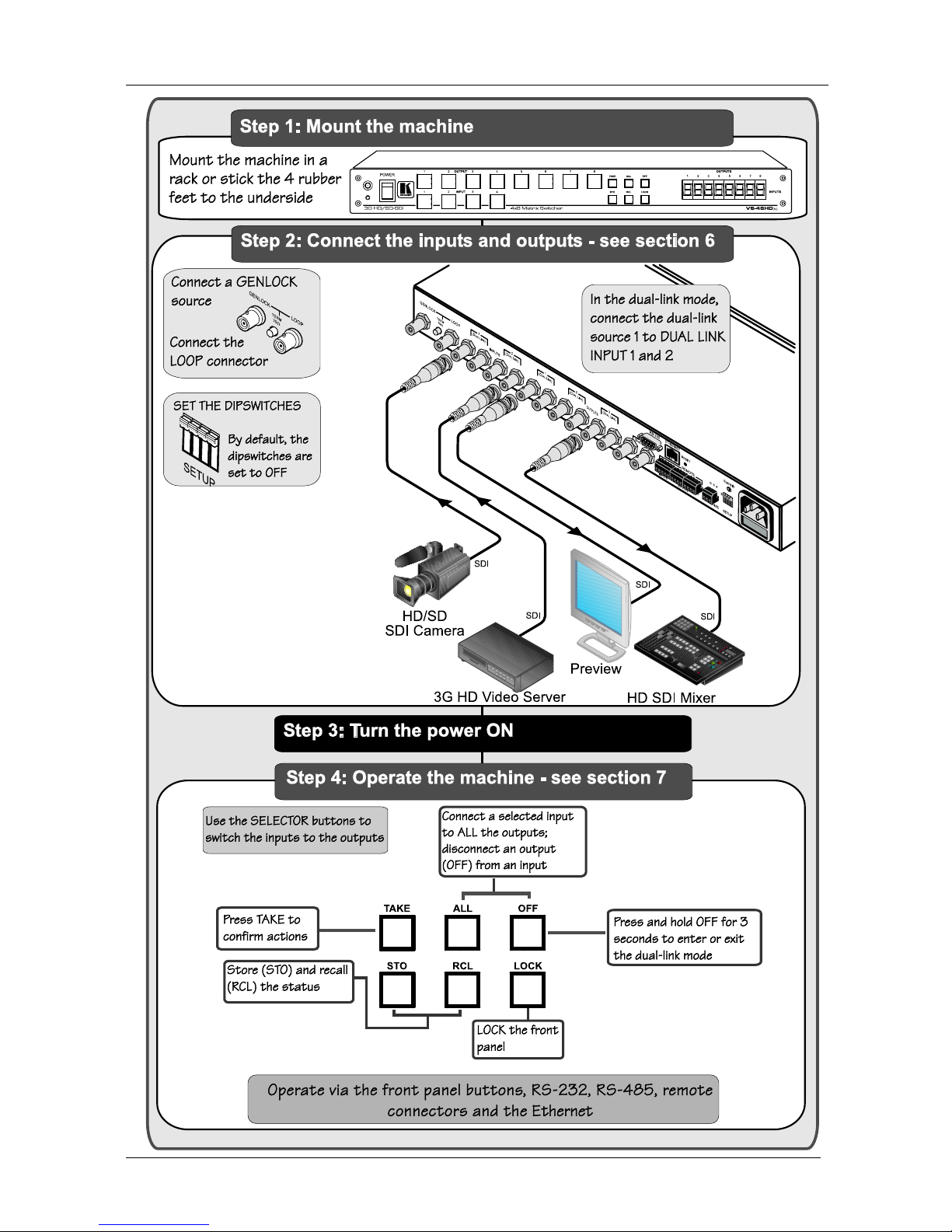
2.1 Quick Start
This quick start chart summarizes the basic setup and operation steps.
1 GROUP 1: Distribution Amplifiers; GROUP 2: Switchers and Matrix Switchers; GROUP 3: Control Systems;
GROUP 4: Format/Standards Converters; GROUP 5: Range Extenders and Repeaters; GROUP 6: Specialty AV Products;
GROUP 7: Scan Converters and Scalers; GROUP 8: Cables and Connectors; GROUP 9: Room Connectivity;
GROUP 10: Accessories and Rack Adapters; GROUP 11: Sierra Products
2 We recommend that you use only the power cord supplied with this device
3 Download up-to-date Kramer user manuals from the Internet at this URL: http://www.kramerelectronics.com
4 The complete list of Kramer cables is on our Web site at http://www.kramerelectronics.com
im Vertrieb von
CAMBOARD Electronics
www.camboard.de
Tel. 07131 911201
Fax 07131 911203
ce-info@camboard.de
KRAMER: SIMPLE CREATIVE TECHNOLOGY
Getting Started
2
im Vertrieb von
CAMBOARD Electronics
www.camboard.de
Tel. 07131 911201
Fax 07131 911203
ce-info@camboard.de

O
verview
3
3 Overview
The Kramer VS-48HDxl can be used as a high-performance 4x8 matrix
switcher or as a dual-link 2x4 switcher, which lets you simultaneously route
any of the inputs to any or all of the outputs for all SDI video signals, using
BNC connectors.
In particular, the VS-48HDxl features:
Cable equalization up to 350m for SD
1
signals, 140m for 1.5GHz HD2
signals, and 120m for 3GHz HD signals
Operation of up to 2.97Gbps – enabling it to be used for standard
definition, high definition and the new 3G high definition serial digital
video signals (SD/HD-SDI)
SMPTE 259M, 292M and 424M and 372M (for dual-link HD-SDI
signals) compliance and support for data rates of 270Mbps, 1483.5Mbps,
1485Mbps and 2970Mbps
Reclocking and equalization on each input, storing and recalling setups,
and a TAKE button for the execution of multiple switches all at once
Selector buttons that automatically light up in different colors—green,
when the VS-48HDxl detects a ‘standard definition’ signal, or blue, when
it detects a ‘high definition’ signal
The ability to switch genlocked video signals according to timing of the
GENLOCK reference input. Switching according to the Bi-level or Trilevel Genlock input according to SMPTE RP-168
3
The VS-48HDxl is housed in a 19" 1U rack-mountable enclosure, and is fed
from a 100-240 VAC universal switching power supply. The unit can be
controlled via the front panel buttons or via:
An infrared remote control transmitter
An infrared remote extension cable transmitter
Remotely, by RS-232 or RS-485 serial commands transmitted by a PC,
touch screen system, or other serial controller
The ETHERNET
Remote contact closure for forced operation
1 Standard Definition (SD) means an NTSC or PAL compatible video format, consisting of 480 (for NTSC) or 576 (for PAL)
lines of interlaced video
2 High Definition (HD) means a video format, consisting of 720 active lines of progressive video or 1080 lines of progressive
or interlaced video
3 The sources must be genlocked to the GENLOCK input in order to switch cleanly
im Vertrieb von
CAMBOARD Electronics
www.camboard.de
Tel. 07131 911201
Fax 07131 911203
ce-info@camboard.de

KRAMER: SIMPLE CREATIVE TECHNOLOGY
Your VS-48HDxl 3G HD/SD SDI 4x8 Matrix Switcher
4
To achieve the best performance:
Connect only good quality connection cables, thus avoiding interference,
deterioration in signal quality due to poor matching, and elevated noise
levels (often associated with low quality cables)
Avoid interference from neighboring electrical appliances that may
adversely influence signal quality and position your Kramer VS-48HDxl
from moisture, excessive sunlight and dust
4 Your VS-48HDxl 3G HD/SD SDI 4x8 Matrix Switcher
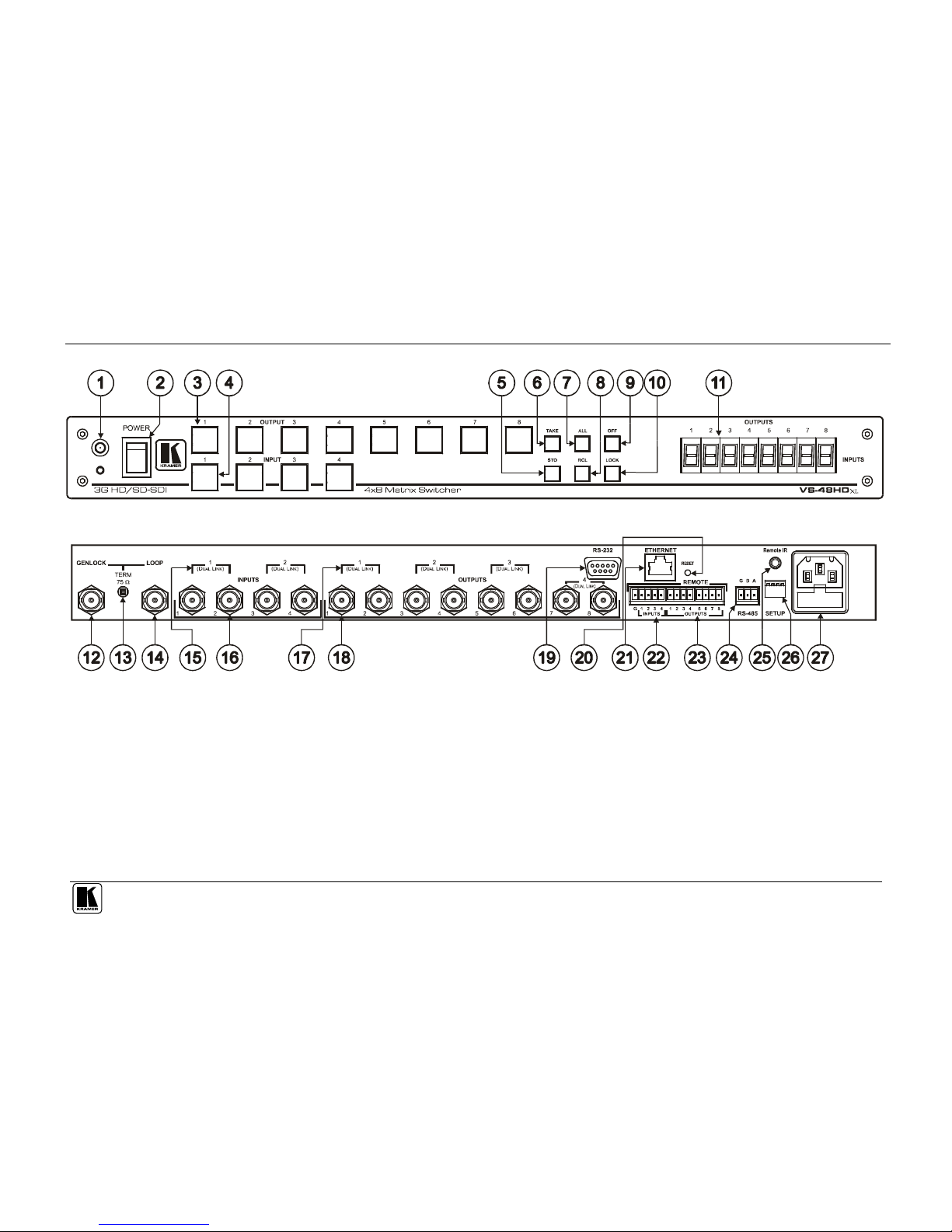
Figure 1, Table 1, and Table 2 define the VS-48HDxl 3G HD/SD SDI 4x8
Matrix Switcher.
im Vertrieb von
CAMBOARD Electronics
www.camboard.de
Tel. 07131 911201
Fax 07131 911203
ce-info@camboard.de
Your VS-48HDxl 3G HD/SD SDI 4x8 Matrix Switcher
5
Figure 1: VS-48HDxl 3G HD/SD SDI 4x8 Matrix Switcher
im Vertrieb von
CAMBOARD Electronics
www.camboard.de
Tel. 07131 911201
Fax 07131 911203
ce-info@camboard.de
KRAMER: SIMPLE CREATIVE TECHNOLOGY
Your VS-48HDxl 3G HD/SD SDI 4x8 Matrix Switcher
6
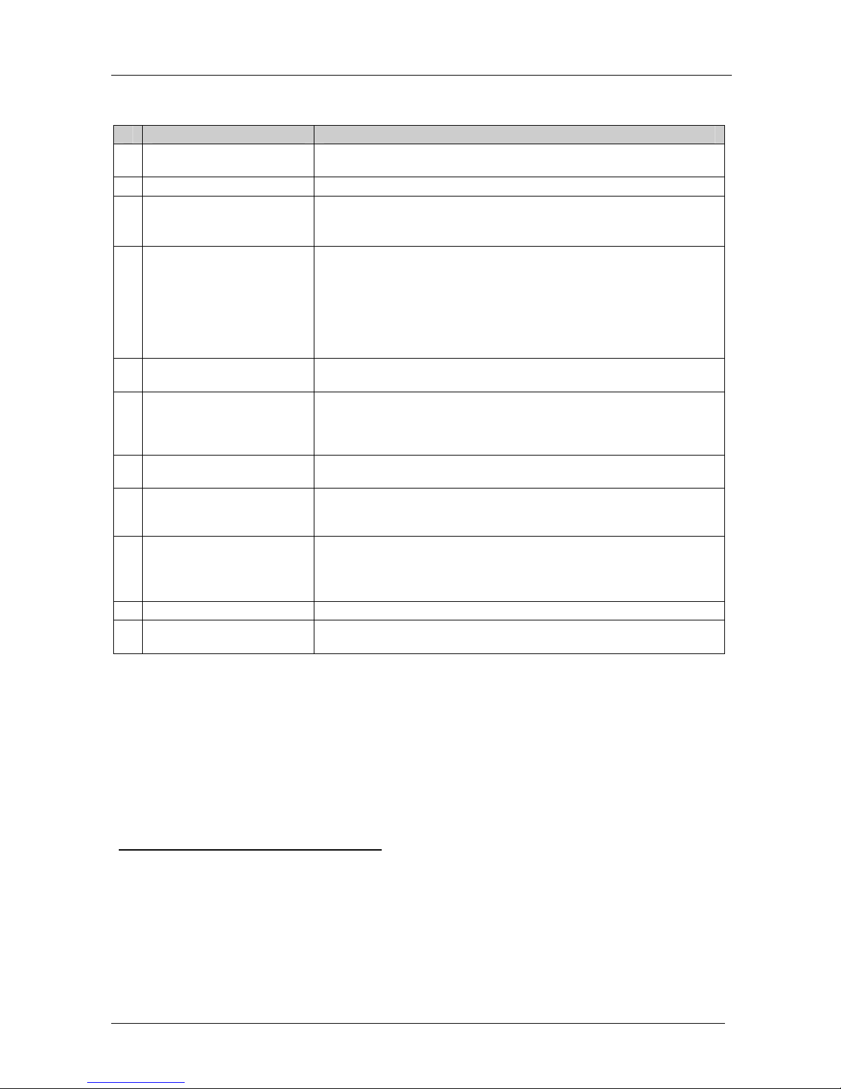
Table 1: Front Panel VS-48HDxl 3G HD/SD SDI 4x8 Matrix Switcher
#
F
eature
F
unction
1 IR Receiver The red LED is illuminated when receiving signals from the Infrared
remote control transmitter
2
POWER Switch Illuminated switch for turning the unit ON or OFF
3
OUTPUT (DUAL LINK)
Selector Buttons
Select the output to which the input is switched (from 1 to 8)
In the dual-link mode, select the output DUAL LINK 1 to DUAL LINK 4
to which the input is switched
4 INPUT (DUAL LINK)
Selector Buttons
Select the input to switch to the output (from 1 to 4)
In the dual-link mode, select input DUAL LINK 1 or DUAL LINK 2 to
switch to the outputs
Press IN buttons 1, 2 and 3 simultaneously to reset the machine to its
factory default values1 (see section 6.6)
Use to set the resolution when switching genlocked video signals (see
section 6.7)
5 STO (STORE) Button Pressing STO followed by an INPUT / OUTPUT button stores the
current setting2
6
TAKE Button Pressing TAKE toggles the mode between the CONFIRM mode3 and
the AT ONCE mode (user confirmation per action is unnecessary).
When in CONFIRM mode, the TAKE button implements a pending
operation
4
7
ALL Button Pressing ALL followed by an INPUT button, connects that input to all
outputs
5
8 RCL (RECALL) Button Pressing the RCL button and the corresponding INPUT / OUTPUT key
displays a setup from the non-volatile memory. After pressing the same
memory location the second time, the settings will take effect
9 OFF Button An OFF-OUT combination disconnects that output from the inputs; an
OFF-ALL combination disconnects all the outputs
Press and hold
6
to toggle between the 4x switcher mode and the
dual-link 2x4 switcher mode
10 LOCK Button Disengages/engages the front panel buttons
1
1 7-segment Display Displays the selected input switched to the output (marked above each
input)
1 The 7-segment display shows 12341234, indicating that the operation mode is normal, and that the setups stored via the
INPUT/OUTPUT buttons have been erased
2 For example, press STO and then the Output button # 3 to store in Setup # 3
3 When in Confirm mode, the TAKE button illuminates
4 See section 7.2
5 For example, press ALL and then Input button # 2 to connect input # 2 to all the outputs
6 For more than 3 seconds
im Vertrieb von
CAMBOARD Electronics
www.camboard.de
Tel. 07131 911201
Fax 07131 911203
ce-info@camboard.de
Y
our VS-48HDxl 3G HD/SD SDI 4x8 Matrix Switcher
7
T
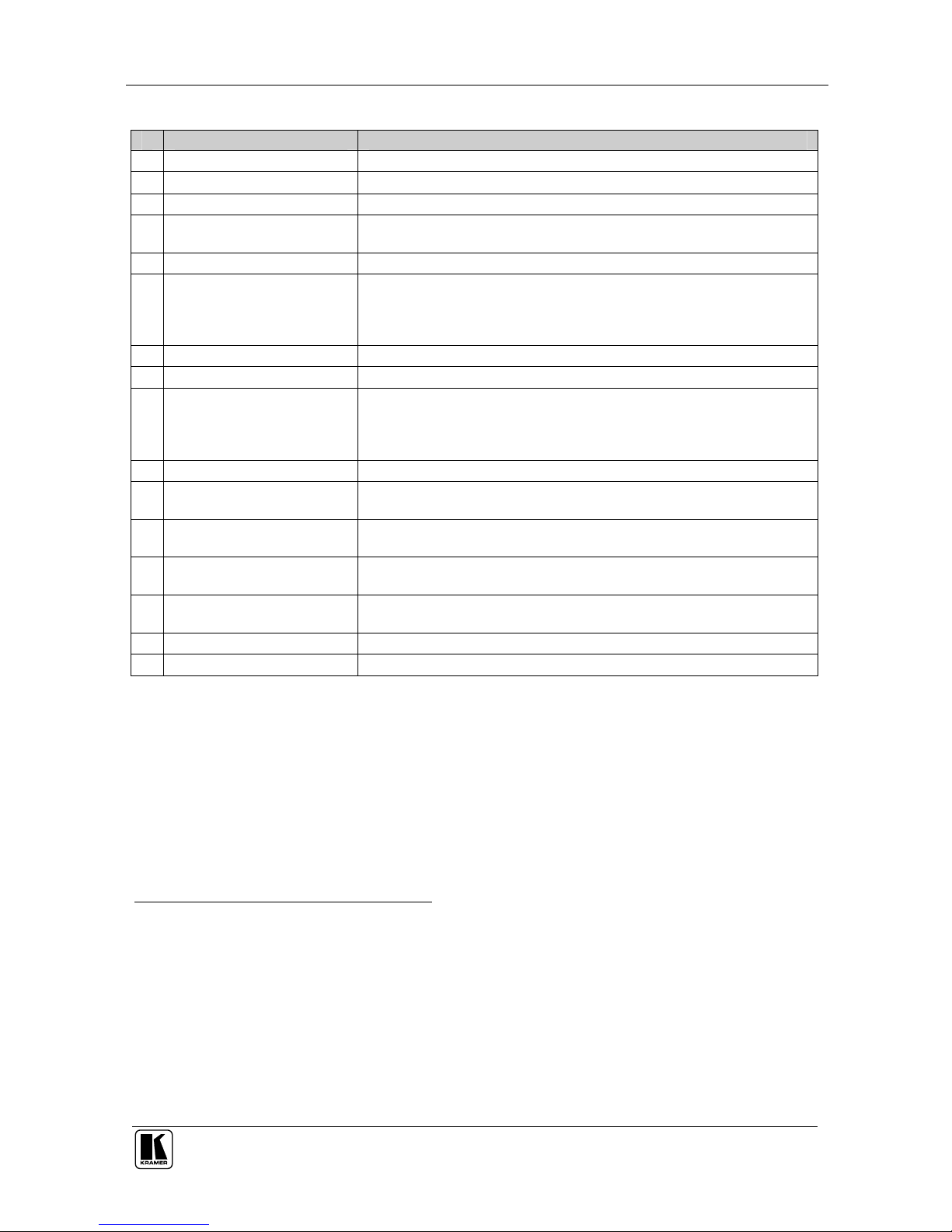
able 2: Rear Panel VS-48HDxl 3G HD/SD SDI 4x8 Matrix Switcher
#
F
eature
F
unction
1
2 GENLOCK BNC Connector Connect to the Genlock source
13
TERM 75
Button Press to terminate the Genlock source (75) or release for looping1
14 LOOP BNC Connector Connect to the GENLOCK connector of the next unit in the line
15 DUAL LINK INPUT BNC
Connectors
In the dual-link mode, connect the source to inputs 1 and 2 and/or inputs 3
and 4 (DUAL LINK 1 and/or DUAL LINK 2)
1
6 INPUT BNC Connectors Connect to the serial digital video sources (from 1 to 4)
17 DUAL LINK OUTPUT BNC
Connectors
In the dual-link mode, connect the acceptors to outputs 1 and 2 and/or
outputs 3 and 4 and/or outputs 5 and 6 and/or outputs 7 and 8 (DUAL
LINK 1 and/or DUAL LINK 2 and/or DUAL LINK 3 and/or DUAL LINK 4,
respectively)
18 OUTPUT BNC Connectors Connect to the serial digital video acceptors (from 1 to 8)
19 RS-232 9-pin D-sub Port Connects to the PC or the Remote Controller
2
0 RESET Button Press to reset Ethernet to factory default definitions2:
IP number 192.168.1.39
Mask – 255.255.255.0
Gateway – 192.168.1.1
21 ETHERNET RJ-45 Connector Connects to the PC or other Serial Controller through computer networking
22 REMOTE INPUT Terminal
Block Connectors
Connect to dry contact switches3 (from 1 to 4)
2
3 REMOTE OUTPUT
Terminal Block Connectors
Connect to dry contact switches (from 1 to 8)
24 RS-485 Detachable
Terminal Block Port
Pin G is for the Ground connection4; pins B (-) and A (+) are for RS-485
2
5 REMOTE IR Opening5 Connects to an external IR receiver unit for controlling the machine via an
IR remote controller (instead of using the front panel IR receiver)
6
26 SETUP Dipswitches Dipswitches for setup of the unit
2
7 Power Connector with Fuse AC connector enabling power supply to the unit
1 Push in to terminate the input. Release when the input extends to another unit
2 First disconnect the power cord and then connect it again while pressing the ETH Factory Reset button. The unit will power
up and load its memory with the factory default definitions
3 See section 6.9
4 The ground connection is sometimes connected to the shield of the RS-485 cable. In most applications, the ground is not
connected
5 Covered by a cap. The 3.5mm connector at the end of the internal IR connection cable fits through this opening
6 Optional. Can be used instead of the front panel (built-in) IR receiver to remotely control the machine (only if the internal
IR connection cable has been installed)
im Vertrieb von
CAMBOARD Electronics
www.camboard.de
Tel. 07131 911201
Fax 07131 911203
ce-info@camboard.de
 Loading...