

Page 1

Kramer Electronics, Ltd.
USER MANUAL
Model:
VS-44HDMI
4 x 4 HDMI Matrix Switcher
Page 2

Contents
i
Contents
1
Introduction 1
2
Getting Started 1
2.1
Quick Start 2
3
Overview 3
3.1
Defining the EDID 3
3.2
About HDMI 4
3.3
Terminology Used in this User Manual 5
4
Your VS-44HDMI 4 x 4 HDMI Matrix Switcher 5
5
Installing the VS-44HDMI in a Rack 8
6
Connecting the VS-44HDMI 4 x 4 HDMI Matrix Switcher 9
7
Operating the VS-44HDMI 4 x 4 HDMI Matrix Switcher 10
7.1
Routing Inputs to Outputs 10
7.2
Disconnecting the Outputs 10
7.3
Storing and Recalling a Setting 10
7.4
Acquiring the EDID 11
7.4.1 Acquiring an EDID from a Single Connected Output 11
7.4.2 Acquiring an EDID from Several Sets of Inputs and Outputs 12
7.4.3 Acquiring an EDID from Several Connected Outputs Automatically 13
7.4.4 Acquiring the Default EDID 13
7.5
Controlling via RS-232 (for example, using a PC) 14
7.6
Controlling via ETHERNET 14
7.6.1 Connecting the ETHERNET Port directly to a PC (Crossover Cable) 14
7.6.2 Connecting the ETHERNET Port via a Network Hub (Straight-Through Cable) 16
7.6.3 Control Configuration via the Ethernet Port 16
8
Technical Specifications 17
9
Hex Table 17
10
Kramer Protocol 2000 18
Figures
Figure 1: VS-44HDMI 4 x 4 HDMI Matrix Switcher Front and Rear Views 6
Figure 2: Connecting the VS-44HDMI 4 x 4 HDMI Matrix Switcher 9
Figure 3: Connecting a PC without using a Null-modem Adapter 14
Figure 4: Local Area Connection Properties Window 15
Figure 5: Internet Protocol (TCP/IP) Properties Window 16
Page 3

KRAMER: SIMPLE CREATIVE TECHNOLOGY
Contents
ii
Tables
Table 1: Terminology Used in this User Manual 5
Table 2: VS-44HDMI 4 x 4 HDMI Matrix Switcher Front Panel Features 7
Table 3: VS-44HDMI 4 x 4 HDMI Matrix Switcher Rear Panel Features 7
Table 4: VS-44HDMI Technical Specifications 17
Table 5: VS-44HDMI Hex Codes for Switching via RS-232/RS-485 17
Table 6: Protocol Definitions 18
Table 7: Instruction Codes for Protocol 2000 19
Page 4

Introduction
1
1 Introduction
Welcome to Kramer Electronics! Since 1981, Kramer Electronics has been
providing a world of unique, creative, and affordable solutions to the vast
range of problems that confront the video, audio, and presentation
professional on a daily basis. In recent years, we have redesigned and
upgraded most of our line, making the best even better! Our 500-plus
different models now appear in eight groups
1
that are clearly defined by
function.
Thank you for purchasing the Kramer TOOLS VS-44HDMI 4 x 4 HDMI
Matrix Switcher, which is ideal for conference room presentations and
advertising applications, as well as for rental and staging
.
Each package includes the following items:
The VS-44HDMI 4 x 4 HDMI Matrix Switcher
Power cord
2
and Null-modem adapter
Windows
®
-based Kramer control software3
Windows
®
-based Ethernet Configuration Manager and Virtual
Serial Port Manager
Kramer RC-IR1/2 Infra-Red Remote Control Transmitter
(including the required batteries and a separate user manual
4
)
This user manual
4
2 Getting Started
We recommend that you:
Unpack the equipment carefully and save the original box and
packaging materials for possible future shipment
Review the contents of this user manual
Use Kramer high performance high resolution cables
5
1 GROUP 1: Distribution Amplifiers; GROUP 2: Video and Audio Switchers, Matrix Switchers and Controllers; GROUP 3:
Video, Audio, VGA/XGA Processors; GROUP 4: Interfaces and Sync Processors; GROUP 5: Twisted Pair Interfaces;
GROUP 6: Accessories and Rack Adapters; GROUP 7: Scan Converters and Scalers; and GROUP 8: Cables and Connectors
2 We recommend that you use only the power cord supplied with this device
3 Downloadable from our Web site at http://www.kramerelectronics.com
4 Download up-to-date Kramer user manuals from our Web site at http://www.kramerelectronics.com
5 The complete list of Kramer cables is on our Web site at http://www.kramerelectronics.com
Page 5
KRAMER: SIMPLE CREATIVE TECHNOLOGY
Getting Started
2
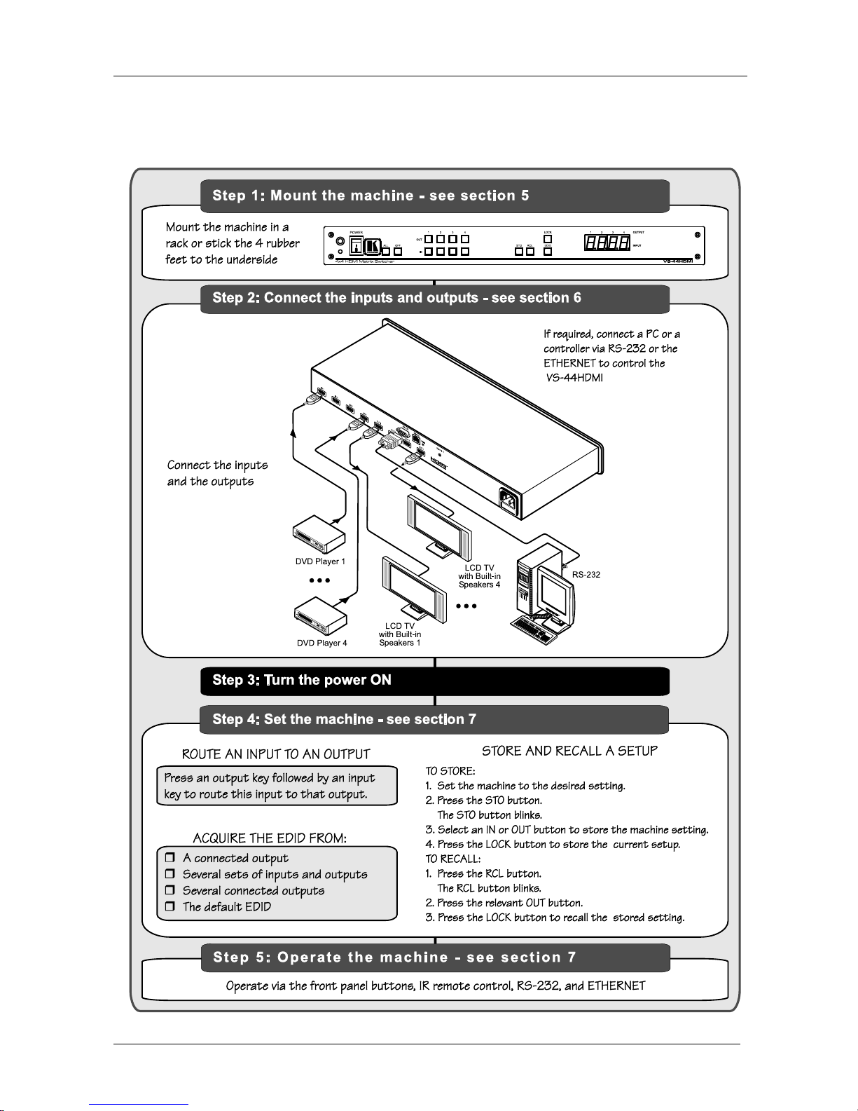
2.1 Quick Start
This quick start chart summarizes the basic setup and operation steps.
Page 6

Overview
3
3 Overview
The VS-44HDMI is a high-quality 4x4 matrix switcher for HDMI signals
that features the following:
Up to 1.65Gbps bandwidth per graphic channel1
Four input selector buttons to switch to the four selectable outputs
Support for HDCP (High Bandwidth Digital Content Protection)
An OFF button to disconnect an output
A PANEL LOCK button to prevent unwanted tampering with the
buttons on the front panel
1U-high, 19” size for mounting in a professional rack enclosure
The VS-44HDMI can be controlled using the front panel buttons, or
remotely via:
RS-232 serial commands transmitted by a touch-screen system,
PC, or other serial controller
The Kramer infra-red remote control transmitter
The ETHERNET
To achieve the best performance:
Use only good quality connection cables2 to avoid interference,
deterioration in signal quality due to poor matching, and elevated
noise levels (often associated with low quality cables).
Avoid interference from neighboring electrical appliances that
may adversely influence signal quality and position your Kramer
VS-44HDMI away from moisture, excessive sunlight and dust
3.1 Defining the EDID
The EDID (Extended Display Identification Data3) is a data-structure,
provided by a display, to describe its capabilities to an HDMI source. The
EDID enables the VS-44HDMI to “know” what kind of monitor is
connected to the output. The EDID includes the name of the manufacturer,
the product type, the timing data supported by the display, the display size,
luminance data and (for digital displays only) the pixel mapping data.
1 Suitable for resolutions up to UXGA at 60Hz, and for all HD resolutions
2 Available from Kramer Electronics on our Web site at http://www.kramerelectronics.com
3 Defined by a standard published by the Video Electronics Standards Association (VESA)
Page 7

KRAMER: SIMPLE CREATIVE TECHNOLOGY
Overview
4
3.2 About HDMI
HDMI (High-Definition Multimedia Interface) is an uncompressed
all-digital1 audio/video interface, widely supported in the entertainment and
home cinema industry. It delivers the highest high-definition image and
sound quality. Note that Kramer Electronics Limited is an HDMI Adopter2
and an HDCP Licensee3.
HDMI features:
A simple4 interface between any audio/video source, such as a
set-top box, DVD player, or A/V receiver and video monitor, such
as a digital flat LCD / plasma television (DTV), over a single
long5 cable
A standard, enhanced, high-definition video, and multi-channel
digital audio6 on a single cable
8-channel digital audio, with spare bandwidth to accommodate future
enhancements and compliance with all ATSC HDTV standards
Superior, uncompressed digital video quality via a single cable7,
and user-friendly connector
Backward-compatibility with DVI (Digital Visual Interface)
Two-way communication between the video source (such as a
DVD player) and the digital television, enabling new functionality
such as automatic configuration and one-button play
Support for existing high-definition video formats (720p, 1080i,
and 1080p/60), standard definition formats such as NTSC or PAL,
as well as 480p and 576p
1 Ensuring an all-digital rendering of video without the losses associated with analog interfaces and their unnecessary digitalto-analog conversions
2 See http://www.hdmi.org/about/adopters_founders.asp
3 See http://www.digital-cp.com/list/
4 With video and multi-channel audio combined into a single cable, the cost, complexity, and confusion of multiple cables
currently used in A/V systems is reduced
5 HDMI technology has been designed to use standard copper cable construction at up to 15m
6 HDMI supports multiple audio formats, from standard stereo to multi-channel surround-sound. HDMI has the capacity to
support Dolby 5.1 audio and high-resolution audio formats
7 HDMI provides the quality and functionality of a digital interface while also supporting uncompressed video formats in a
simple, cost-effective manner
Page 8

Your VS-44HDMI 4 x 4 HDMI Matrix Switcher
5
3.3 Terminology Used in this User Manual
Table 1 defines some terms that are used in this user manual.
Table 1: Terminology Used in this User Manual
Term Definition
802.3 The standard specification for ETHERNET that is maintained by the Institute of
Electrical and Electronics Engineers (IEEE).
Dynamic Host Configuration
Protocol (DHCP)
Allows the network administrator to distribute IP addresses from a central point
and automatically send a new IP address when an Ethernet point is plugged into
a different network location
Gateway A network position serving as an entry to another network. On the Internet, a
node or stopping point can be either a gateway node or a host (end-point) node.
IP Address A 32-binary digit number that identifies each sender or receiver (within a network
via a particular server or workstation) of data (HTML pages or e-mails) that is
sent in packets across the Internet. Every device connected to an IP network
must have a unique IP address. This address is used to reference the specific
unit.
Local Area Network (LAN) Computers sharing a common communications line or wireless link, which often
share a server within a defined geographic area.
Media Access Control
(MAC) Address
A computer's unique hardware number (or address) in a LAN or other network.
On an Ethernet LAN, the (MAC) address is identical to the Ethernet address.
Transmission Control
Protocol/Internet Protocol
(TCP/IP)
The basic communication language or protocol of the Internet that breaks the
message into appropriately sized packets for the network, and can be used as a
communications protocol in an intranet or an extranet.
4 Your VS-44HDMI 4 x 4 HDMI Matrix Switcher
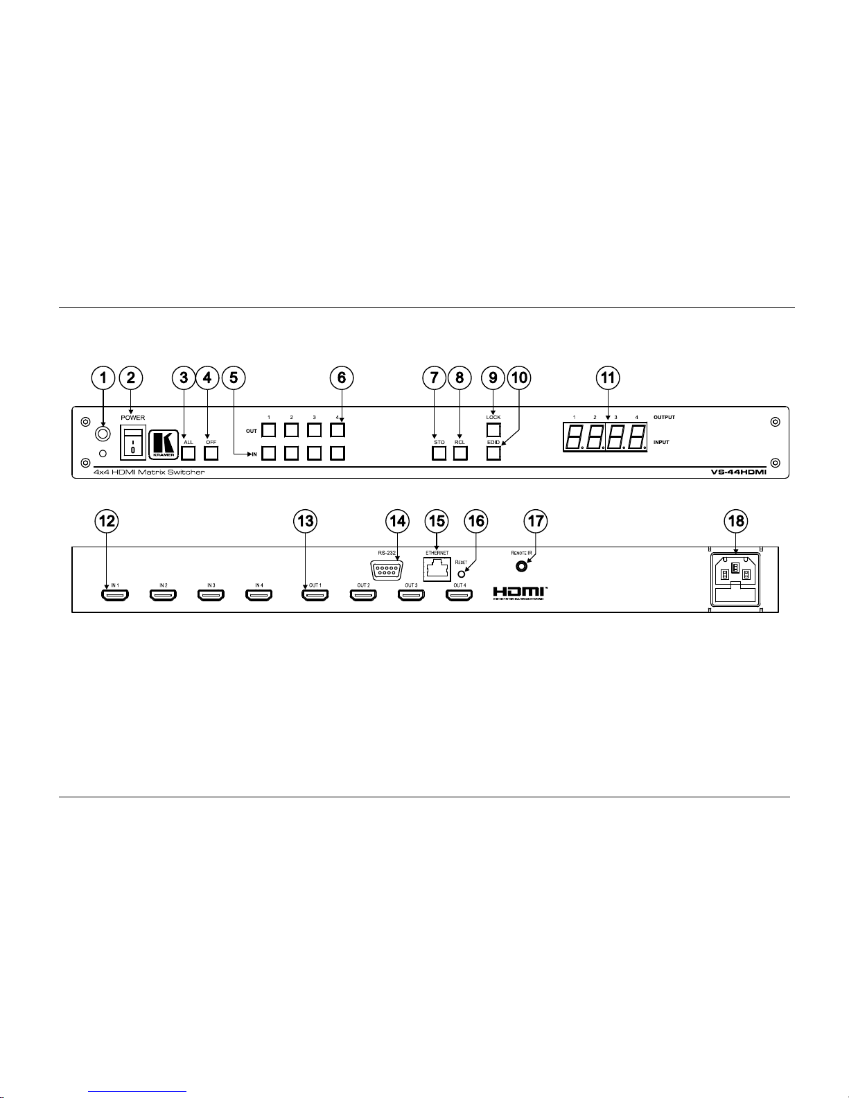
Figure 1, Table 2, and Table 3 define the unit.
Page 9
KRAMER: SIMPLE CREATIVE TECHNOLOGY
Your VS-44HDMI 4 x 4 HDMI Matrix Switcher
6
Figure 1: VS-44HDMI 4 x 4 HDMI Matrix Switcher Front and Rear Views
Page 10

Your VS-44HDMI 4 x 4 HDMI Matrix Switcher
7
Table 2: VS-44HDMI 4 x 4 HDMI Matrix Switcher Front Panel Features
# Feature Function
1 IR Receiver LED The red LED is illuminated when receiving signals from the Infra-red
remote control transmitter
2 POWER Switch Illuminated switch for turning the unit ON or OFF
3 ALL Button Use ALL to select all inputs or all outputs (see section 7.1)
4 OFF Button Use OFF to disconnect one or all outputs (see section 7.2)
5 IN Buttons Press an INPUT selector button to select an input (from 1 to 4)
6 OUT Buttons Press an OUTPUT selector button to select an output (from 1 to 4)
7 STO Button Press to store an input setting
8 RCL Button Press to recall an input setting
9 LOCK Button Press to toggle disengaging the front panel buttons and to acquire the
EDID (see section 7.4)
10 EDID Button1 Press to acquire the EDID
11 7-segment Display Displays the selected input switched to the output (marked above
each input)
Table 3: VS-44HDMI 4 x 4 HDMI Matrix Switcher Rear Panel Features
# Feature Function
12 IN HDMI Connectors Connect to the HDMI sources (from 1 to 4)
13 OUT HDMI Connectors Connect to the HDMI acceptors (from 1 to 4)
14 RS-232 DB-9F Port Connects to the PC or the RS-232 Remote Controller
15 ETHERNET Connector Connects to the PC or other Ethernet Controller
16 RESET Button Press the reset button to reset to the ETHERNET factory default
definitions2:
IP number 192.168.1.39
Mask – 255.255.255.0
Gateway – 192.168.1.1
17 REMOTE IR Connector Connect to an external IR receiver unit for controlling the machine via
an IR remote controller (instead of using the front panel IR receiver)
18 Power Connector with
Fuse
AC connector enabling power supply to the unit
1 Illuminates when configuring the EDID
2 First disconnect the power cord and then connect it again while pressing the RESET button. The unit will power up and load
its memory with the factory default definitions
Page 11
KRAMER: SIMPLE CREATIVE TECHNOLOGY
Installing the VS-44HDMI in a Rack
8
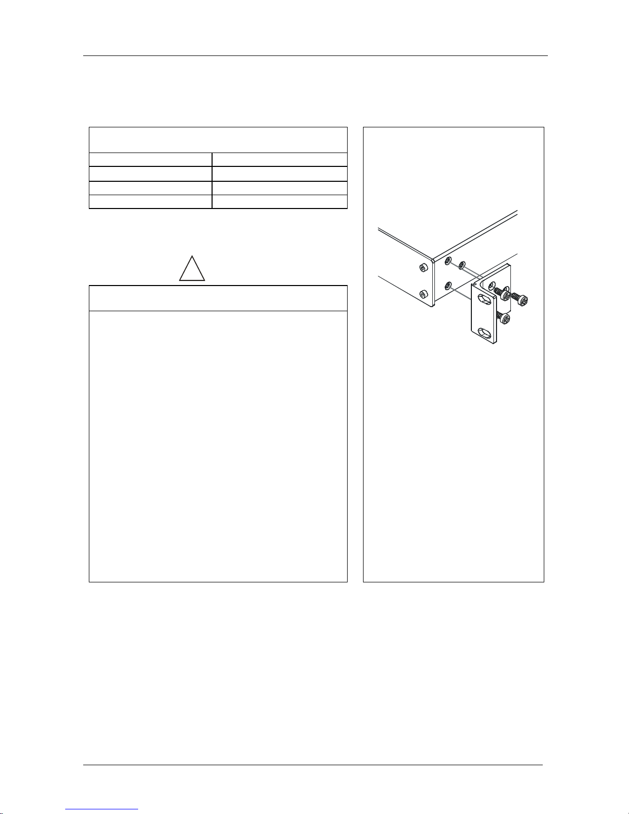
5 Installing the VS-44HDMI in a Rack
This section describes how to install the VS-44HDMI in a rack.
Before Installing on a Rack
How to Rack Mount
Before installing on a rack, be sure that the environment is
within the recommended range:
Operating temperature range +5º to +45º C (41º to 113º F)
Operating humidity range 10 to 90% RHL, non-condensing
Storage temperature range -20º to +70º C (-4º to 158º F)
Storage humidity range 5 to 95% RHL, non-condensing
CAUTION!!
When installing on a 19" rack, avoid hazards by taking
care that:
1. It is located within the recommended environmental
conditions, as the operating ambient temperature of a
closed or multi unit rack assembly may exceed the
room ambient temperature.
2. Once rack mounted, enough air will still flow around
the machine.
3. The machine is placed straight in the correct
horizontal position.
4. You do not overload the circuit(s). When connecting
the machine to the supply circuit, overloading the
circuits might have a detrimental effect on overcurrent
protection and supply wiring. Refer to the appropriate
nameplate ratings for information. For example, for
fuse replacement, see the value printed on the
product label.
5. The machine is earthed (grounded) in a reliable way
and is connected only to an electricity socket with
grounding. Pay particular attention to situations where
electricity is supplied indirectly (when the power cord
is not plugged directly into the socket in the wall), for
example, when using an extension cable or a power
strip, and that you use only the power cord that is
supplied with the machine.
To rack-mount a machine:
1. Attach both ear brackets to the
machine. To do so, remove the
screws from each side of the
machine (3 on each side), and
replace those screws through the
ear brackets.
2. Place the ears of the machine
against the rack rails, and insert the
proper screws (not provided)
through each of the four holes in the
rack ears.
Note that:
In some models, the front panel
may feature built-in rack ears
Detachable rack ears can be
removed for desktop use
Always mount the machine in the
rack before you attach any cables
or connect the machine to the
power
If you are using a Kramer rack
adapter kit (for a machine that is not
19"), see the Rack Adapters user
manual for installation instructions
(you can download it at:
http://www.kramerelectronics.com)
Page 12
Connecting the VS-44HDMI 4 x 4 HDMI Matrix Switcher
9
6 Connecting the VS-44HDMI 4 x 4 HDMI Matrix Switcher
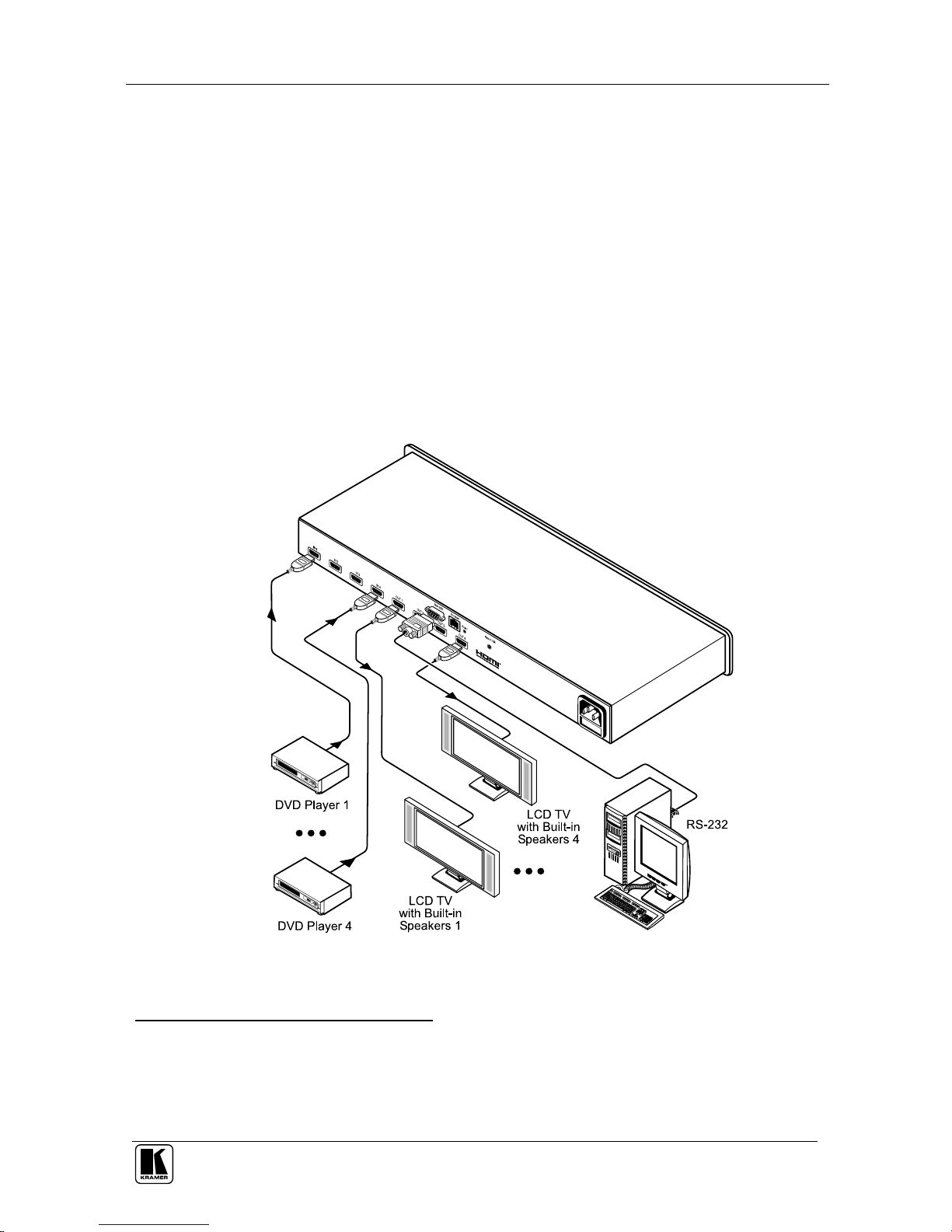
To connect the VS-44HDMI, as the example in Figure 2 illustrates, do the
following1:
1. Connect up to four HDMI sources2 (for example, DVD players) to the IN
HDMI connectors.
2. Connect the OUT HDMI connectors to up to four HDMI acceptors3 (for
example, LCD displays with built-in speakers).
3. If required, connect a PC and/or controller to the RS-232 port (see section
7.5) and/or the ETHERNET port (see section 7.6).
4. Connect the power cord (not shown in Figure 2).
5. If required, acquire the EDID (see section 7.1).
Figure 2: Connecting the VS-44HDMI 4 x 4 HDMI Matrix Switcher
1 Switch OFF the power on each device before connecting it to your VS-44HDMI. After connecting your VS-44HDMI,
switch on its power and then switch on the power on each device
2 You do not have to connect all the HDMI sources
3 You do not have to connect all outputs
Page 13

KRAMER: SIMPLE CREATIVE TECHNOLOGY
Operating the VS-44HDMI 4 x 4 HDMI Matrix Switcher
10
7 Operating the VS-44HDMI 4 x 4 HDMI Matrix Switcher
This section describes how to:
Route inputs to outputs (see section 7.1)
Disconnecting outputs (see section 7.2)
Store and recall a setup (see section 7.3)
Acquire the EDID (see section 7.4)
Control the machine via RS-232 (see section 7.5)
Control the machine via the ETHERNET port (see section 7.6)
7.1 Routing Inputs to Outputs
To route an input to an output:
Press an OUT key, followed by an IN key to route this input to
that output
To route one input to all outputs:
Press ALL followed by an IN button. The input is routed to all
outputs
7.2 Disconnecting the Outputs
To disconnect one output:
Press the OUT button of the output to disconnect and press OFF
To disconnect all outputs at once:
Press the ALL button and then press OFF. This disconnects all the
outputs
7.3 Storing and Recalling a Setting
You can use the STO and RCL buttons to store up to 8 setups and then recall
them.
To store a setting:
1. Set the machine to the desired setting.
For example, press the OUT 3 button and IN 4 button1.
2. Press the STO button.
The STO button blinks.
1 You can set all the switcher IN-OUT buttons
Page 14

Operating the VS-44HDMI 4 x 4 HDMI Matrix Switcher
11
3. Select an OUT or IN SELECT button to store the machine setting (for
example, OUT 4).
4. Press the LOCK button1 to store the current setup.
In this example, the OUT 4 button stores the setting.
To recall a setup:
1. Press the RCL button.
The RCL button blinks.
2. Press the relevant OUT or IN button that stored the setting.
In this example, press OUT 4.
3. Press the LOCK button to recall the stored setting.
7.4 Acquiring the EDID
You can acquire the EDID from:
A single connected output (see section 7.4.1)
Several sets of inputs and outputs (see section 7.4.2)
Several connected outputs automatically (see section 7.4.3)
The default EDID (see section 7.4.4)
7.4.1 Acquiring an EDID from a Single Connected Output
To acquire or change the EDID of a new output display:
1. Power ON the VS-44HDMI.
2. Connect the required acceptor to the output from which you want to acquire
the EDID.
3. Press the EDID and STO buttons simultaneously and hold them for 3
seconds.
Both buttons flash.
4. Press the IN SELECTOR button to which the EDID will be copied.
The selected input number flashes on the display.
5. Select the OUT SELECTOR button from which the EDID will be acquired.
6. Press the EDID button.
The process is complete when the display returns to normal.
1 You have to press the LOCK button within 10 seconds, before the store operation times out
Page 15

KRAMER: SIMPLE CREATIVE TECHNOLOGY
Operating the VS-44HDMI 4 x 4 HDMI Matrix Switcher
12
7.4.2 Acquiring an EDID from Several Sets of Inputs and Outputs
To acquire the EDID several sets of inputs and outputs (for example, OUT 1
to IN 1 and OUT 6 to IN 3), do the following:
1. Power ON the VS-44HDMI.
2. Connect the required acceptors to the outputs from which you want to
acquire the EDID.
3. Press the EDID and STO buttons simultaneously and hold them for 3
seconds.
Both buttons flash.
4. Press the SELECT IN button to which the first EDID will be copied (for
example, IN 1).
The selected input number flashes on the display.
5. Press the SELECT OUT button from which the first EDID will be acquired
(for example, OUT 1).
6. Press the SELECT IN 1 button again.
The IN 1 button ceases to flash.
7. Press another SELECT IN to which the next EDID will be copied (for
example, IN 3).
The selected input number flashes on the display.
8. Press the SELECT OUT button from which the next EDID will be acquired
(for example, OUT 4).
9. Press the SELECT IN 3 button again.
The IN 3 button ceases to flash.
10. Press the SELECT IN buttons to which you want to copy the EDID (for
example, IN 1 and IN 3).
11. Make sure that the relevant input numbers flash on the display.
12. Press the EDID button.
The process is complete when the display returns to normal.
Page 16

Operating the VS-44HDMI 4 x 4 HDMI Matrix Switcher
13
7.4.3 Acquiring an EDID from Several Connected Outputs
Automatically
To automatically acquire or change the EDID of several output displays1:
1. Power ON the VS-44HDMI.
2. Connect the required acceptors to the outputs from which you want to
acquire the EDID.
3. Press the EDID and STO buttons simultaneously and hold them for 3
seconds.
Both buttons flash.
4. Press the SELECT IN button to which the EDID will be copied.
The selected input number flashes on the display.
5. Press the OFF button until a “–“ (hyphen) appears on the display.
6. Press the EDID button.
The process is complete when the display returns to normal.
7.4.4 Acquiring the Default EDID
To reset to the default EDID, do the following:
1. Power ON the VS-44HDMI.
2. Press the EDID and STO buttons simultaneously and hold them for 3
seconds.
Both buttons flash.
3. Press the SELECT IN button to which the EDID will be copied.
The selected input number flashes on the display.
4. Press the OFF button until a "0" (zero) appears on the display.
5. Press the EDID button.
The process is complete when the display returns to normal.
1 The EDID acquired is a weighted average of all the connected outputs. For example, if several displays with different
resolutions are connected to the outputs, the acquired EDID supports all the resolutions, as well as other parameters included
in the EDID
Page 17
KRAMER: SIMPLE CREATIVE TECHNOLOGY
Operating the VS-44HDMI 4 x 4 HDMI Matrix Switcher
14
7.5 Controlling via RS-232 (for example, using a PC)
To connect a PC to the VS-44HDMI unit, using the Null-modem adapter
provided with the machine (recommended):
Connect the RS-232 DB9 rear panel port on the VS-44HDMI unit
to the Null-modem adapter and connect the Null-modem adapter
with a 9-wire flat cable to the RS-232 DB9 port on your PC
To connect a PC to the VS-44HDMI unit, without using a Null-modem
adapter:
Connect the RS-232 DB9 port on your PC to the RS-232 DB9 rear
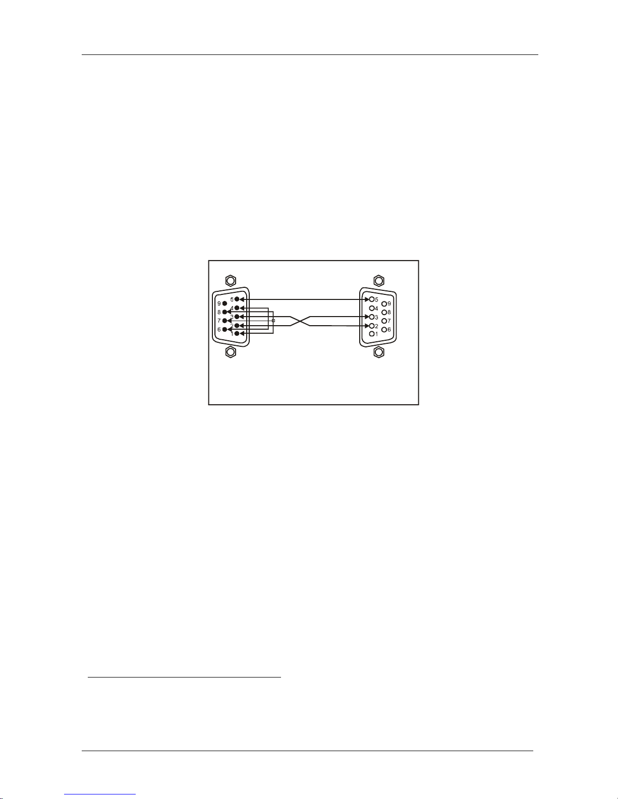
panel port on the Master VS-44HDMI unit, as Figure 3 illustrates
Female DB9 (From PC)
PIN 4 Connected to PIN 6
PINS 8, 7, 1 Connected together
If a Shielded cable is used, connect the shield to PIN 5
PIN 5 Connected to PIN 5 (Ground)
PIN 3 Connected to PIN 2
PIN 2 Connected to PIN 3
Male DB9
Figure 3: Connecting a PC without using a Null-modem Adapter
7.6 Controlling via ETHERNET
You can connect the VS-44HDMI via the Ethernet, using a crossover cable
(see section 7.6.1) for direct connection to the PC or a straight-through
cable (see section 7.6.2) for connection via a network hub or network
router1.
7.6.1 Connecting the ETHERNET Port directly to a PC (Crossover
Cable)
You can connect the Ethernet port of the VS-44HDMI to the Ethernet port
on your PC, via a crossover cable with RJ-45 connectors.
1 After connecting the Ethernet port, you have to install and configure your Ethernet Port. For detailed instructions, see the
“Ethernet Configuration (FC-11) guide.pdf” file in the technical support section on our Web site:
http://www.kramerelectronics.com
Page 18
Operating the VS-44HDMI 4 x 4 HDMI Matrix Switcher
15
This type of connection is recommended for identification of the factory default
IP Address of the VS-44HDMI during the initial configuration
After connecting the Ethernet port, configure your PC as follows:
1. Right-click the My Network Places icon on your desktop.
2. Select Properties.
3. Right-click Local Area Connection Properties.
4. Select Properties.
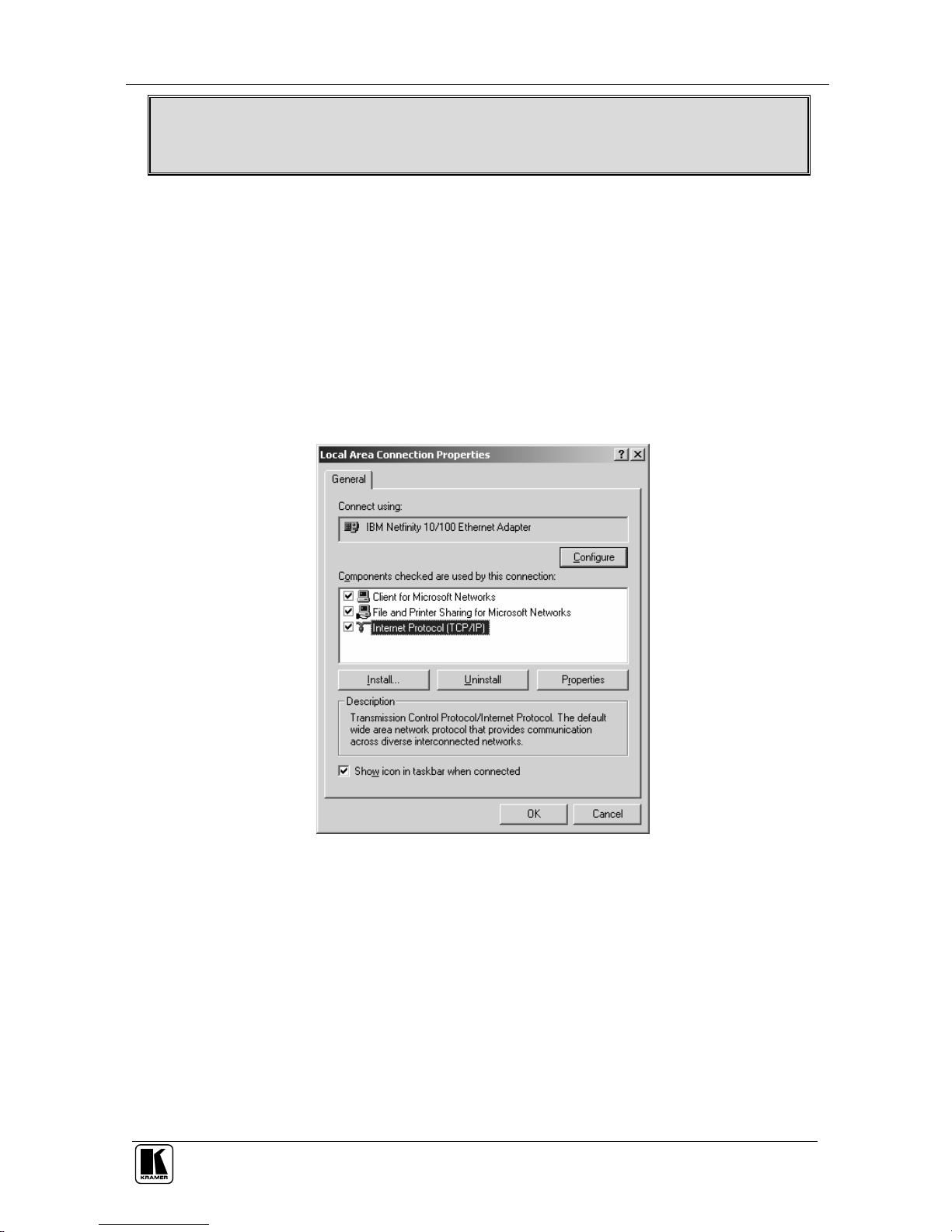
The Local Area Connection Properties window appears.
5. Select the Internet Protocol (TCP/IP) and click the Properties Button (see
Figure 4).
Figure 4: Local Area Connection Properties Window
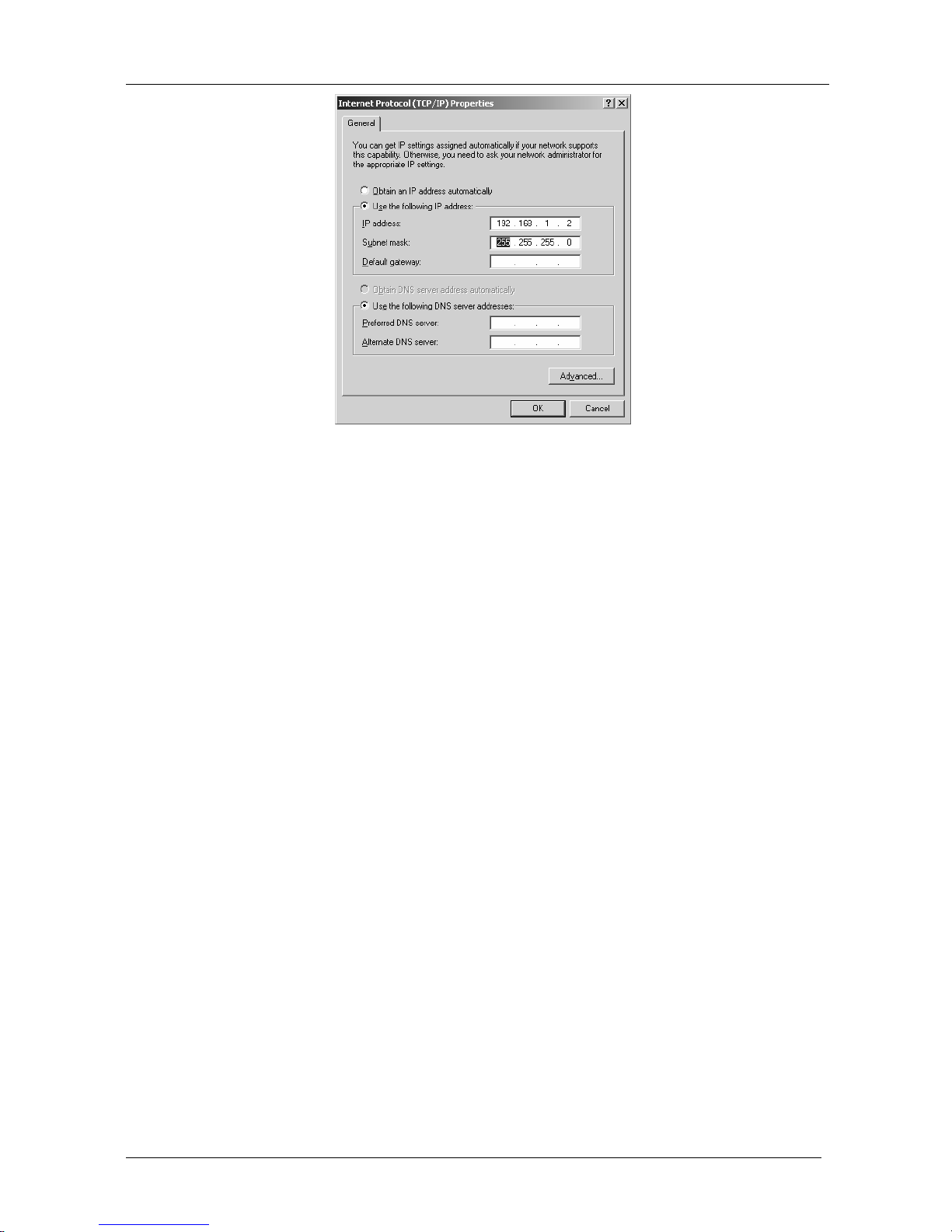
6. Select Use the following IP Address, and fill in the details as shown in
Figure 5.
7. Click OK.
Page 19
KRAMER: SIMPLE CREATIVE TECHNOLOGY
Operating the VS-44HDMI 4 x 4 HDMI Matrix Switcher
16
Figure 5: Internet Protocol (TCP/IP) Properties Window
7.6.2 Connecting the ETHERNET Port via a Network Hub (Straight-Through
Cable)
You can connect the Ethernet port of the VS-44HDMI to the Ethernet port
on a network hub or network router, via a straight-through cable with RJ-45
connectors.
7.6.3 Control Configuration via the Ethernet Port
To control several units via the Ethernet, connect the Master unit
(Machine # 1) via the Ethernet port to the LAN port of your PC. Use your
PC initially to configure the settings (see section 7.6).
Page 20

Technical Specifications
17
8 Technical Specifications
The VS-44HDMI technical specifications are shown in Table 4:
Table 4: VS-44HDMI Technical Specifications1
INPUTS: 4 HDMI Connectors
OUTPUTS: 4 HDMI Connectors
BANDWIDTH: Supports up to 1.65Gbps bandwidth per graphic channel
COMPLIANCE WITH
HDMI STANDARD:
Supports HDMI 1.1 and HDCP
MAX RESOLUTION: Up to UXGA; 1080p, 1920 x 1200
POWER SOURCE:
100240VAC; 50/60Hz, 28VA
CONTROLS: Front panel buttons, Infra-red remote control transmitter, RS-232, Ethernet
DIMENSIONS: 19 " x 7 " x 1U W, D, H
WEIGHT: 2.5 kg. (5.5 lbs.) approx.
ACCESSORIES: Power cord, IR transmitter
OPTIONS: Kramer HDMI cables2
9 Hex Table
Table 5 lists the Hex values for a single machine (MACHINE # 1):
Table 5: VS-44HDMI Hex Codes for Switching via RS-232/RS-485
OUT 4 OUT 3 OUT 2 OUT 1
IN 1
IN 2
IN 3
IN 4
1 Specifications are subject to change without notice
2 For best results, use Kramer cables such as the C-HDMI/HDMI series, the C-HDMI-DVI series and/or our HDMI over fiber
optics C-FOHM/FOHM series
Page 21

KRAMER: SIMPLE CREATIVE TECHNOLOGY
Kramer Protocol 2000
18
10 Kramer Protocol 20001
The VS-44HDMI is compatible with Kramer’s Protocol 20002 (version
0.50) (below). This RS-232/RS-485 communication protocol uses four
bytes of information as defined below. For RS-232, a null-modem
connection between the machine and controller is used. The default data
rate is 9600 baud, with no parity, 8 data bits and 1 stop bit.
Table 6: Protocol Definitions
MSB LSB
DESTINATION
INSTRUCTION
0 D N5 N4 N3 N2 N1 N0
7 6 5 4 3 2 1 0
1st byte
INPUT
1 I6 I5 I4 I3 I2 I1 I0
7 6 5 4 3 2 1 0
2nd byte
OUTPUT
1 O6 O5 O4 O3 O2 O1 O0
7 6 5 4 3 2 1 0
3rd byte
MACHINE NUMBER
1 OVR X M4 M3 M2 M1 M0
7 6 5 4 3 2 1 0
4th byte
1st BYTE: Bit 7 – Defined as 0.
D – “DESTINATION” : 0 - for sending information to the switchers (from the PC);
1 - for sending to the PC (from the switcher).
N5…N0 – “INSTRUCTION”
The function that is to be performed by the switcher(s) is defined by the INSTRUCTION (6 bits). Similarly, if a function is
performed via the machine’s keyboard, then these bits are set with the INSTRUCTION NO., which was performed. The
instruction codes are defined according to the table below (INSTRUCTION NO. is the value to be set for N5…N0).
2nd BYTE: Bit 7 – Defined as 1.
I6…I0 – “INPUT”.
When switching (ie. instruction codes 1 and 2), the INPUT (7 bits) is set as the input number which is to be switched.
Similarly, if switching is done via the machine’s front-panel, then these bits are set with the INPUT NUMBER which was
switched. For other operations, these bits are defined according to the table.
3rd BYTE: Bit 7 – Defined as 1.
O6…O0 – “OUTPUT”.
When switching (ie. instruction codes 1 and 2), the OUTPUT (7 bits) is set as the output number which is to be switched.
Similarly, if switching is done via the machine’s front-panel, then these bits are set with the OUTPUT NUMBER which was
switched. For other operations, these bits are defined according to the table.
4th BYTE: Bit 7 – Defined as 1.
Bit 5 – Don’t care.
OVR – Machine number override.
M4…M0 – MACHINE NUMBER.
1 You can download our user-friendly “Software for Calculating Hex Codes for Protocol 2000” from the technical support
section on our Web site at: http://www.kramerelectronics.com
2 The instruction codes in Table 7 are a sub-set of the Protocol 2000. You can find the full protocol on our Web site at
http://www.kramerelectronics.com
Page 22

Kramer Protocol 2000
19
Used to address machines in a system via their machine numbers. When several machines are controlled from a single serial
port, they are usually configured together with each machine having an individual machine number. If the OVR bit is set, then
all machine numbers will accept (implement) the command, and the addressed machine will reply.
For a single machine controlled via the serial port, always set M4…M0 = 1, and make sure that the machine itself is
configured as MACHINE NUMBER = 1.
Table 7: Instruction Codes for Protocol 2000
Note: All values in the table are decimal, unless otherwise stated.
INSTRUCTION DEFINITION FOR SPECIFIC INSTRUCTION
# DESCRIPTION INPUT OUTPUT
NOTE
0 RESET VIDEO 0 0 1
1 SWITCH VIDEO Set equal to video input
which is to be switched
(0 = disconnect)
Set equal to video output which is
to be switched
(0 = to all the outputs)
2, 15
3 STORE VIDEO STATUS Set as SETUP # 0 - to store
1 - to delete
2, 3, 15
4 RECALL VIDEO STATUS Set as SETUP # 0 2, 3, 15
5 REQUEST STATUS OF A
VIDEO OUTPUT
Set as SETUP # Equal to output number whose
status is reqd
4, 3
15 REQUEST WHETHER SETUP
IS DEFINED / VALID INPUT IS
DETECTED
SETUP #
or
Input #
0 - for checking if setup is defined
1 - for checking if input is valid
8
30 LOCK FRONT PANEL 0 - Panel unlocked
1 - Panel locked
0 2
31 REQUEST WHETHER PANEL
IS LOCKED
0 0 16
61 IDENTIFY MACHINE 1 - video machine name
2 - audio machine name
3 - video software version
4 - audio software version
5 - RS422 controller name
6 - RS422 controller
version
7 - remote control name
8 - remote software
version
9 - Protocol 2000 revision
0 - Request first 4 digits
1 - Request first suffix
2 - Request second suffix
3 - Request third suffix
10 - Request first prefix
11 - Request second prefix
12 - Request third prefix
13
62 DEFINE MACHINE 1 - number of inputs
2 - number of outputs
3 - number of setups
1 - for video
2 - for audio
3 - for SDI
4 - for remote panel
5 - for RS-422 controller
14
NOTES on the above table:
NOTE 1 - When the master switcher is reset, (e.g. when it is turned on), the reset code is sent to the PC. If this code is sent to
the switchers, it will reset according to the present power-down settings.
NOTE 2 - These are bi-directional definitions. That is, if the switcher receives the code, it will perform the instruction; and if
the instruction is performed (due to a keystroke operation on the front panel), then these codes are sent. For example, if the
HEX code
01 85 88 83
was sent from the PC, then the switcher (machine 3) will switch input 5 to output 8. If the user switched input 1 to output 7
via the front panel keypad, then the switcher will send HEX codes:
41 81 87 83
to the PC.
When the PC sends one of the commands in this group to the switcher, then, if the instruction is valid, the switcher replies by
sending to the PC the same four bytes that it was sent (except for the first byte, where the DESTINATION bit is set high).
NOTE 3 - SETUP # 0 is the present setting. SETUP # 1 and higher are the settings saved in the switcher's memory, (i.e. those
used for Store and Recall).
Page 23

KRAMER: SIMPLE CREATIVE TECHNOLOGY
Kramer Protocol 2000
20
NOTE 4 - The reply to a "REQUEST" instruction is as follows: the same instruction and INPUT codes as were sent are
returned, and the OUTPUT is assigned the value of the requested parameter. The replies to instructions 10 and 11 are as per
the definitions in instructions 7 and 8 respectively. For example, if the present status of machine number 5 is breakaway
setting, then the reply to the HEX code
0B 80 80 85
would be HEX codes
4B 80 81 85
NOTE 8 - The reply is as in TYPE 3 above, except that here the OUTPUT is assigned with the value 0 if the setup is not
defined / no valid input is detected; or 1 if it is defined / valid input is detected.
NOTE 13 - This is a request to identify the switcher/s in the system. If the OUTPUT is set as 0, and the INPUT is set as 1, 2,
5 or 7, the machine will send its name. The reply is the decimal value of the INPUT and OUTPUT. For example, for a 2216,
the reply to the request to send the audio machine name would be (HEX codes):
7D 96 90 81 (i.e. 128dec+ 22dec for 2nd byte, and 128dec+ 16dec for 3rd byte).
If the request for identification is sent with the INPUT set as 3 or 4, the appropriate machine will send its software version
number. Again, the reply would be the decimal value of the INPUT and OUTPUT - the INPUT representing the number in
front of the decimal point, and the OUTPUT representing the number after it. For example, for version 3.5, the reply to the
request to send the version number would be (HEX codes):
7D 83 85 81 (i.e. 128dec+ 3dec for 2nd byte, 128dec+ 5dec for 3rd byte).
If the OUTPUT is set as 1, then the ASCII coding of the lettering following the machine’s name is sent. For example, for the
VS-7588YC, the reply to the request to send the first suffix would be (HEX codes):
7D D9 C3 81 (i.e. 128dec+ ASCII for “Y” ; 128dec+ ASCII for “C” ).
NOTE 14 - The number of inputs and outputs refers to the specific machine which is being addressed, not to the system. For
example, if six 16X16 matrices are configured to make a 48X32 system (48 inputs, 32 outputs), the reply to the HEX code
3E 82 81 82 (ie. request the number of outputs)
would be HEX codes
7E 82 90 82
ie. 16 outputs
NOTE 15 – When the OVR bit (4th byte) is set, then the “video” commands have universal meaning. For example,
instruction 1 (SWITCH VIDEO) will cause all units (including audio, data, etc.) to switch. Similarly, if a machine is in
“FOLLOW” mode, it will perform any “video” instruction.
NOTE 16 - The reply to the “REQUEST WHETHER PANEL IS LOCKED” is as in NOTE 4 above, except that here the
OUTPUT is assigned with the value 0 if the panel is unlocked, or 1 if it is locked.
Page 24
21
Page 25

Kramer Electronics, Ltd.
Web site: www.kramerelectronics.com
E-mail: [email protected]
P/N: 2900-000359 REV 1
For the latest information on our products and a list of Kramer
distributors, visit our Web site: www.kramerelectronics.com
where updates to this user manual may be found.
We welcome your questions, comments and feedback.
Caution
Safety Warning:
Disconnect the unit from the power supply before
opening/servicing.
 Loading...