

Kramer VS-42HDCP User Manual

KRAMER ELECTRONICS LTD.
USER MANUAL
MODEL:
VS-42HDCP
4x2 DVI Matrix Switcher
P/N: 2900-300218 Rev 4

VS-42HDCP – Contents
i
Contents
1 Introduction 1
2 Getting Started 2
2.1 Achieving the Best Performance 2
2.2 Safety Instructions 2
2.3 Recycling Kramer Products 3
3 Overview 4
3.1 About Fast Switching 5
3.2 Defining the VS-42HDCP 4x2 DVI Matrix Switcher 5
4 Installing in a Rack 8
5 Connecting the VS-42HDCP 9
6 Operating the VS-42HDCP 4x2 DVI Matrix Switcher 11
6.1 Routing Inputs to Outputs 11
6.2 Disconnecting the Outputs 11
6.3 Storing and Recalling a Switching Setting 12
6.4 Changing the Port Switching Speed 13
6.5 Setting HDCP to On/Off 13
6.6 Locking and Unlocking the Front Panel 14
6.7 Switching Between Protocol 2000 and Protocol 3000 14
6.8 Acquiring the EDID 14
6.9 Resetting the IP Parameters 15
7 Controlling the VS-42HDCP 16
7.1 Connecting to the VS-42HDCP via RS-232 16
7.2 Connecting via Ethernet 16
7.3 Using the IR Transmitter 17
7.4 Firmware Upgrade 17
8 Technical Specifications 18
9 Default Communication Parameters 19
10 Default EDID 20
11 Kramer Protocol 2000 22
12 Protocol 3000 25
12.1 Kramer Protocol 3000 Syntax 25
12.2 Kramer Protocol 3000 Commands 28
12.3 Kramer Protocol 3000 – Detailed Commands 29
Figures
Figure 1: VS-42HDCP 4x2 DVI Matrix Switcher Front Panel 6
Figure 2: VS-42HDCP 4x2 DVI Matrix Switcher Rear Panel 7
Figure 3: Connecting to the VS-42HDCP Rear Panel 10

VS-42HDCP - Introduction
1
1
1 Introduction
Welcome to Kramer Electronics! Since 1981, Kramer Electronics has been
providing a world of unique, creative, and affordable solutions to the vast range of
problems that confront video, audio, presentation, and broadcasting professionals
on a daily basis. In recent years, we have redesigned and upgraded most of our
line, making the best even better!
Our 1,000-plus different models now appear in 14 groups that are clearly defined
by function: GROUP 1: Distribution Amplifiers; GROUP 2: Switchers and Routers;
GROUP 3: Control Systems; GROUP 4: Format/Standards Converters; GROUP 5:
Range Extenders and Repeaters; GROUP 6: Specialty AV Products; GROUP 7:
Scan Converters and Scalers; GROUP 8: Cables and Connectors; GROUP 9:
Room Connectivity; GROUP 10: Accessories and Rack Adapters; GROUP 11:
Sierra Video Products; GROUP 12: Digital Signage; GROUP 13: Audio; and
GROUP 14: Collaboration.
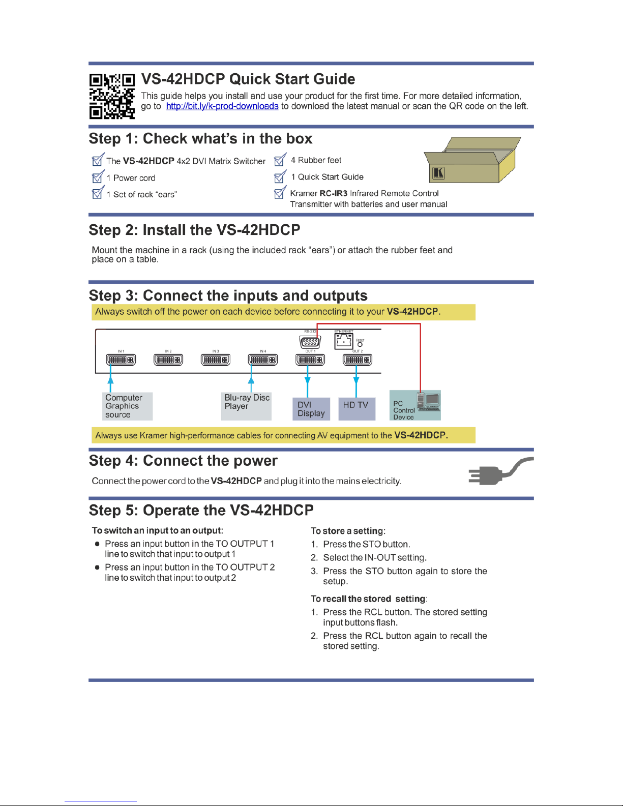
Congratulations on purchasing your Kramer VS-42HDCP 4x2 DVI Matrix Switcher,
which is ideal for conference room presentations and advertising applications as
well as for rental and staging.

2
VS-42HDCP - Getting Started
2 Getting Started
We recommend that you:
Unpack the equipment carefully and save the original box and packaging
materials for possible future shipment
Review the contents of this user manual
Go to http://www.kramerelectronics.com/support/product_downloads.asp
to check for up-to-date user manuals, application programs, and to check if
firmware upgrades are available (where appropriate).
2.1 Achieving the Best Performance
To achieve the best performance:
Use only good quality connection cables (we recommend Kramer high-
performance, high-resolution cables) to avoid interference, deterioration in
signal quality due to poor matching, and elevated noise levels (often
associated with low quality cables
Do not secure the cables in tight bundles or roll the slack into tight coils
Avoid interference from neighboring electrical appliances that may adversely
influence signal quality
Position your Kramer VS-42HDCP away from moisture, excessive sunlight
and dust
This equipment is to be used only inside a building. It may only be
connected to other equipment that is installed inside a building.
2.2 Safety Instructions
Caution:
There are no operator serviceable parts inside the unit
Warning:
Use only the power cord that is supplied with the unit
Warning:
Do not open the unit. High voltages can cause
electrical shock! Servicing by qualified personnel only
Warning:
Disconnect the power and unplug the unit from the wall
before installing
i
!
!

VS-42HDCP - Getting Started
3
3
2.3 Recycling Kramer Products
The Waste Electrical and Electronic Equipment (WEEE) Directive 2002/96/EC
aims to reduce the amount of WEEE sent for disposal to landfill or incineration by
requiring it to be collected and recycled. To comply with the WEEE Directive,
Kramer Electronics has made arrangements with the European Advanced
Recycling Network (EARN) and will cover any costs of treatment, recycling and
recovery of waste Kramer Electronics branded equipment on arrival at the EARN
facility. For details of Kramer’s recycling arrangements in your particular country
go to our recycling pages at http://www.kramerelectronics.com/support/recycling/.

4
VS-42HDCP - Overview
3 Overview
The VS-42HDCP is a high quality 4x2 DVI matrix switcher. It reclocks and
equalizes the signals and can route any of the four DVI/HDMI (over DVI-D
connector) inputs to one or both DVI/HDMI outputs simultaneously.
DVI-D (Digital). Note that only the digital signal (DVI D) is available on the DVI connector.
In particular, the VS-42HDCP features:
Up to 6.75Gbps data rate (2.25Gbps per graphics channel)
Suitable for resolutions up to UXGA and 1080p at 60Hz
Support for HDCP (High Definition Digital Content Protection)
HDMI Support – HDMI (3D, Deep Color, x.v.Color™, Lip Sync)
3D pass-through
Support for up to 7.1 multi-channel audio
I-EDIDPro™ Kramer Intelligent EDID Processing™ – Intelligent EDID
handling and processing algorithm ensures Plug and Play operation for
HDMI systems
Kramer reKlocking™ and Equalization Technology that rebuilds the digital
signal to travel longer distances
A LOCK button to prevent unwanted tampering with the buttons on the front
panel
Support for Kramer Protocol 2000 and Protocol 3000
You can control the VS-42HDCP using the front panel buttons or remotely via:
RS-232 serial commands transmitted by a touch screen system, PC or other
serial controller
The Kramer RC-IR3 infrared remote control transmitter
The infrared remote extension cable transmitter (optional), see Section 7.3
The Ethernet port

VS-42HDCP - Overview
5
5
3.1 About Fast Switching
Older display devices required a longer time between the loss of one digital signal
and the introduction of another, as well as a physical disconnection of the
interconnecting cable in order to be able to detect and adjust to the new video
attributes and parameters. Normal switching, therefore, introduced a 5V signal
disconnection along with a delay in switching. Many newer display devices,
however, are now capable of “on-the-fly” switching.
Depending on the display device in use, the VS-42HDCP allows for fast switching
(minor reset and the connection kept alive) and extra fast switching (no reset and
the connection kept alive). Using the fast and extra fast switching modes allows for
fraction-of-a-second switching times when using high performance display devices
or when using a scaler on the video output.
3.2 Defining the VS-42HDCP 4x2 DVI Matrix Switcher
This section defines the VS-42HDCP.
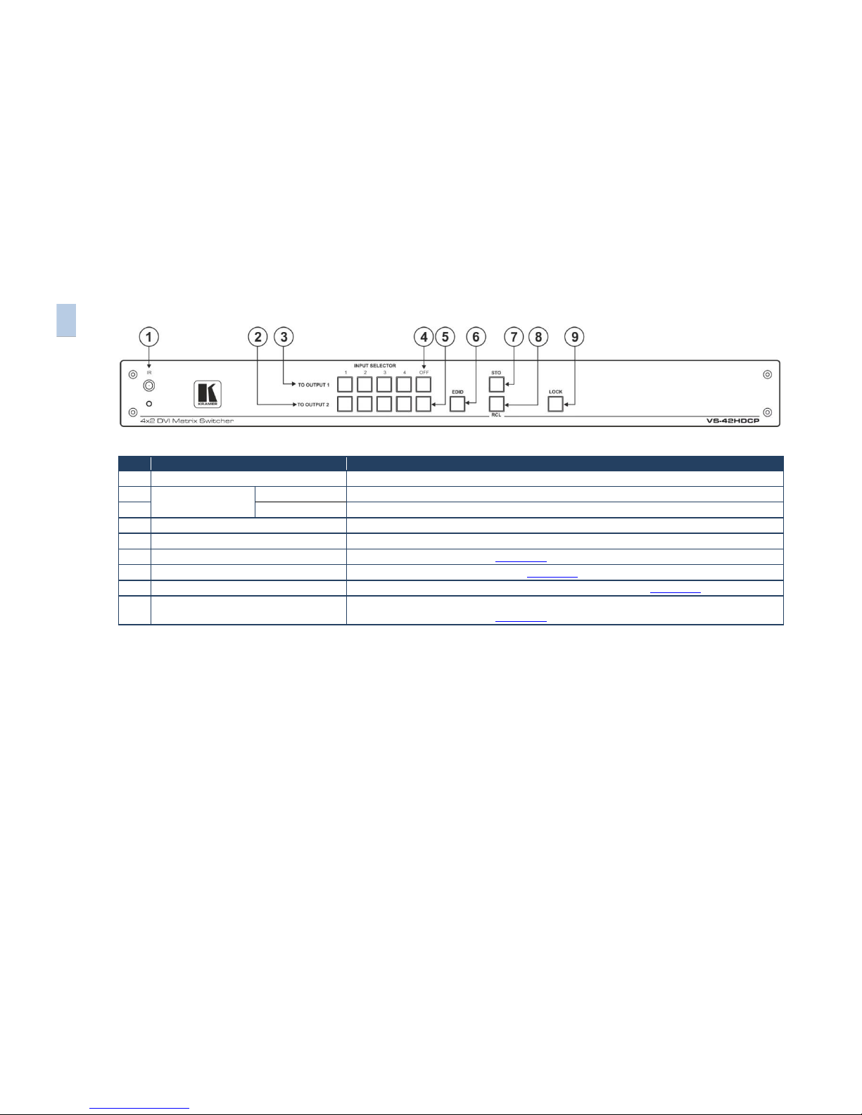
Figure 1: VS-42HDCP 4x2 DVI Matrix Switcher Front Panel
#
Feature
Function
1
IR Receiver and LED
IR remote control sensor. LED lights yellow when receiving an IR signal
2
INPUT SELECTOR
Buttons
TO OUTPUT 2
Press one of the 4 inputs to switch it to Output 2
3
TO OUTPUT 1
Press one of the 4 inputs to switch it to Output 1
4
OFF Button Output 1
Press to disconnect output 1 from the inputs
5
OFF Button Output 2
Press to disconnect output 2 from the inputs
6
EDID Button
Press to acquire the EDID (see Section 6.7)
7
STO Button
Press to store a switching setting (see Section 6.3)
8
RCL Button
Press to recall a stored switching configuration from a preset (see Section 6.3)
9
LOCK Button
Press and hold to toggle the locking/release of the front panel buttons.
Press to acquire the EDID (see Section 6.7)
6
VS-42HDCP – Overview
VS-42HDCP – Overview
7
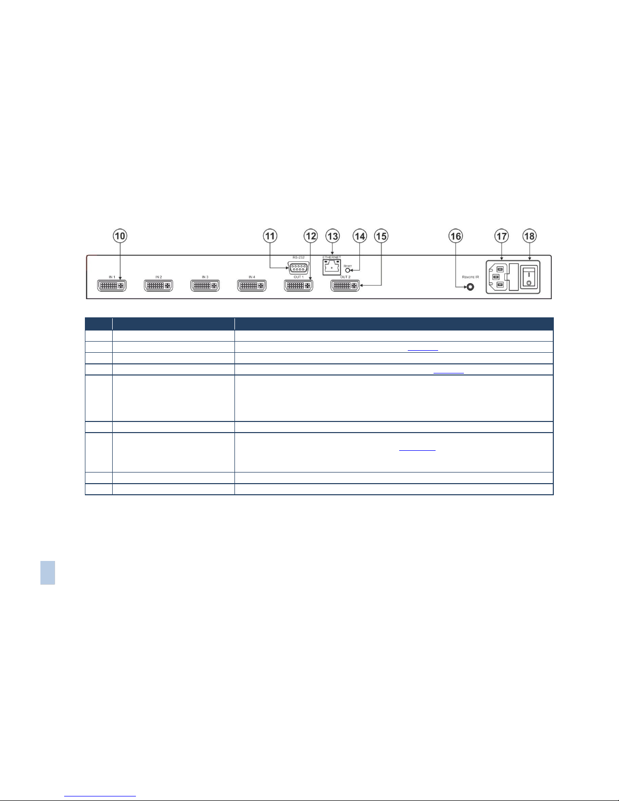
Figure 2: VS-42HDCP 4x2 DVI Matrix Switcher Rear Panel
#
Feature
Function
10
IN DVI Connectors
Connect to the DVI/HDMI (over DVI-D connector) sources (from 1 to 4)
11
RS-232 9-pin D-sub (F) Connector
Connect to a PC or the serial remote controller (see Section 9)
12
OUT 1 DVI Connector
Connect to a DVI/HDMI acceptor
13
ETHERNET RJ-45 Connector
Connect to a PC or other Ethernet controller via a LAN (see Section 9)
14
RESET Button
Press to reset to factory default definitions:
IP number 192.168.1.39, Mask – 255.255.0.0, Gateway – 0.0.0.0
First, disconnect the power cord and then connect it again while pressing the ETH Factory
Reset button. The unit powers up and loads its memory with the factory default definitions and
erases all stored preset
15
OUT 2 DVI Connector
Connect to a DVI acceptor
16
REMOTE IR opening
Connect to an external IR receiver unit for controlling the machine via an IR remote controller
(instead of using the front panel IR receiver), see Section 7.3
Covered by a cap. The 3.5mm jack at the end of the internal IR connection cable fits into this
opening
17
Power Connector with Fuse
AC connector, enabling power supply to the unit
18
POWER Switch
Switch for turning the unit ON or OFF
8
VS-42HDCP - Installing in a Rack
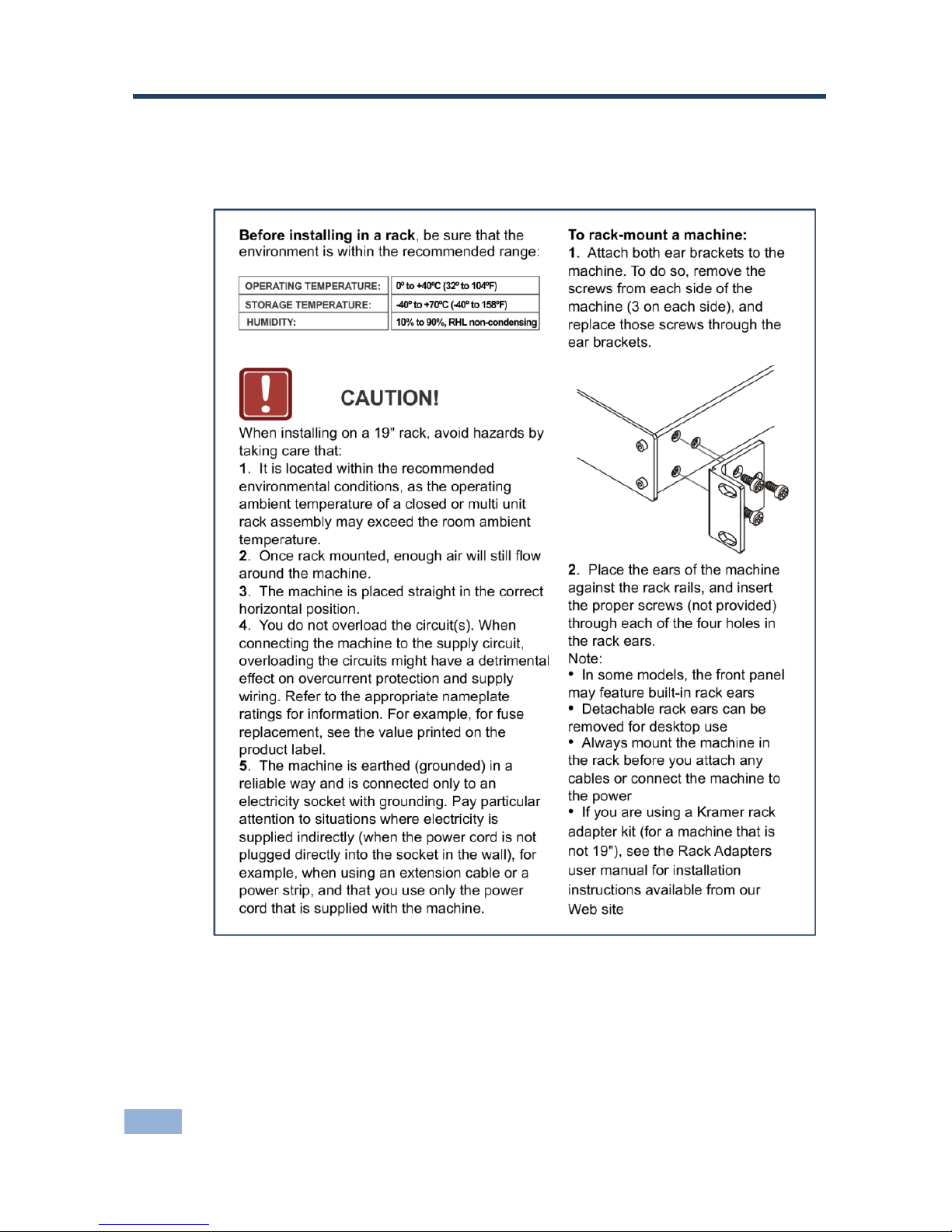
4 Installing in a Rack
This section provides instructions for rack mounting the unit.

VS-42HDCP - Connecting the VS-42HDCP
9
9
5 Connecting the VS-42HDCP
Always switch off the power to each device before connecting it to your
VS-42HDCP. After connecting your VS-42HDCP, connect its power
and then switch on the power to each device.
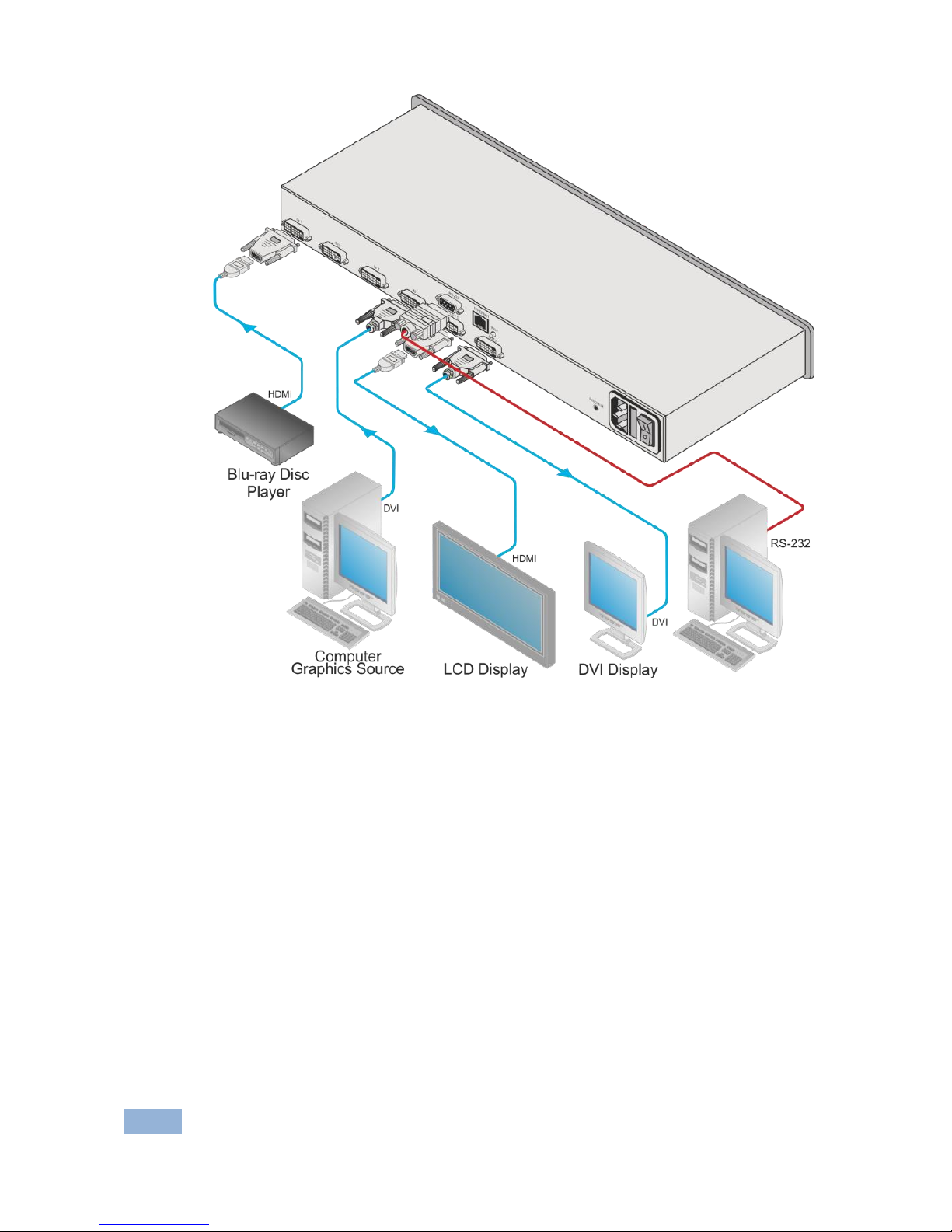
To connect the VS-42HDCP as illustrated in the example in Figure 3:
1. Connect up to four DVI sources (for example, DVD players and/or Blu-ray
disc players) to the IN DVI connectors.
You do not have to connect all the sources.
2. Connect the two OUT DVI connectors to up to two DVI acceptors (for
example, DVI and/or LCD displays).
You do not have to connect all the outputs.
3. If required, connect a PC and/or controller to the RS-232 port (see
Section 7.1) and/or the Ethernet port (see Section 7.2).
4. Connect the power cord (not shown in Figure 3).
5. Power the device.
6. If required, acquire the EDID (see Section 6.7).
i
10
VS-42HDCP - Connecting the VS-42HDCP
Figure 3: Connecting to the VS-42HDCP Rear Panel

VS-42HDCP - Operating the VS-42HDCP 4x2 DVI Matrix Switcher
11
11
6 Operating the VS-42HDCP 4x2 DVI Matrix
Switcher
This section describes how to:
Switch inputs to outputs (see Section 6.1)
Disconnect outputs (see Section 6.2)
Store and recall a setup (see Section 6.3)
Change the port switching speed (see Section 6.4)
Set HDCP on or off (see Section 6.5)
Lock and unlock the front panel (see Section 6.6)
Switch between protocol 2000 and protocol 3000 (see Section 6.7)
Acquire the EDID (see Section 6.8)
Reset the Ethernet configuration to default values (see Section 6.9)
6.1 Routing Inputs to Outputs
To route an input to an output:
Press an INPUT button (from 1 to 4) in the TO OUTPUT 1 row to select an
input to switch to output 1
Press an INPUT button (from 1 to 4) in the TO OUTPUT 2 row to select an
input to switch to output 2
6.2 Disconnecting the Outputs
To disconnect output 1, press the OFF button on the TO OUTPUT 1 line and to
disconnect output 2, press the OFF button on the TO OUTPUT 2 line. The OFF
button illuminates.

12
VS-42HDCP - Operating the VS-42HDCP 4x2 DVI Matrix Switcher
6.3 Storing and Recalling a Switching Setting
You can use the STO and RCL buttons to store the current setup and then recall
it.
The VS-42HDCP stores only one setting in memory. Storing a new
setting overwrites the previous one.
To store a setting:
1. Press the STO button.
The STO button illuminates and the:
Currently selected input buttons illuminate
The selected Input buttons in the current configuration flash
For example, if both outputs are currently disconnected, both OFF buttons
illuminate and the current setting input buttons (for example, INPUT 1 to
OUTPUT 1 and INPUT 3 to OUTPUT 2) flash.
2. Set the machine to the desired setting.
For example, press INPUT SELECTOR button 3 on the TO OUTPUT 1 line
and INPUT SELECTOR button 1 on the TO OUTPUT 2 line.
These buttons flash
3. Press the STO button again to store the current setup (You have to press
the STO button within 10 seconds, before the store operation times-out).
The STO button no longer illuminates and the current setting is stored in the
non-volatile memory.
To recall a setup:
1. Press the RCL button.
The RCL button illuminates as well as the current setting input buttons, and
the input buttons of the stored setup flash.
2. Press the RCL button once again to recall the stored setting.
i
 Loading...