

Page 1

KRAMER ELECTRONICS LTD.
USER MANUAL
MODELS:
VS-41AV
4x1 Audio-Video Switcher
VS-101AV
10x1 Video/Audio-Stereo
Switcher
VS-4X
4x1 Balanced Audio Switcher
P/N: 2900-002009 Rev 2
Page 2
Page 3

VS-41AV, VS101AV, VS-4X – Contents i
Contents
1 Introduction 1
2 Getting Started 2
2.1 Achieving the Best Performance 2
3 Overview 3
3.1 Defining the VS-41A V 4x1 Audio-Video Switcher 4
3.2 Defining the VS-101AV 10x1 Video/Audio-Stereo Switcher 5
3.3 Defining the VS-4X 4x1 Balanced Audio Switcher 6
4 Connecting and Operating the Switchers 7
4.1 Connecting the VS-41AV 4x1 Audio-Video Switcher 8
4.2 Connecting the VS-101AV 10x1 Video/Audio-Stereo S witc her 9
4.3 Connecting the VS-4X 4x1 Balanced Audio Switcher 10
4.4 Operating the Switchers 10
5 Technical Specifications 11
Figures
Figure 1: VS-41AV 4x1 Audio-Video Switcher 4
Figure 2: VS-101AV 10x1 Video/Audio-Stereo S witc her 5
Figure 3: VS-4X 4x1 Balanced Audio Switcher 6
Figure 4: Connecting the VS-41AV 8
Figure 5: Connecting the VS-101AV 9
Figure 6: Connecting the VS-4X 10
Page 4

VS-41AV, VS101AV, VS-4X - Introduction 1
1 Introduction
Welcome to Kramer Electronics! Since 1981, Kramer Electronics has been
providing a world of unique, creative, and affordable solutions to the vast range of
problems that confront the video, audio, presentation, and broadcasting
professional on a daily basis. In recent years, we have redesigned and upgraded
most of our line, making the best even better!
Our 1,000-plus different models now appear in 11 groups that are clearly defined
by function: GROUP 1: Distribution Amplifiers; GROUP 2: Switchers and Matrix
Switchers; GROUP 3: Control Systems; GROUP 4: Format/Standards Converters;
GROUP 5: Range Extenders and Repeaters; GROUP 6: Specialty AV Products;
GROUP 7: Scan Converters and Scalers; GROUP 8: Cables and Connectors;
GROUP 9: Room Connectivity; GROUP 10: Accessories and Rack Adapters and
GROUP 11: Sierra Products.
Congratulations on purchasing your Kramer VS-41AV, VS101AV, VS-4X
switchers that are ideal for the following typical applicati ons:
• Small editing systems
• Security, CCTV, and home theater systems
• Any application where a passive “hard-wired” signal path is preferred
Page 5

2 VS-41AV, VS101AV, VS-4X - Getting Started
2 Getting Started
We recommend that you:
• Unpack the equipment carefully and save the original box and packaging
materials for possible future shipment
• Review the contents of t his user manual
• Use Kramer high-performance, high-resolution cables
Go to http://www.kramerelectronics.com to check for up-to-date
user manuals, application programs, and to check if firmware
upgrades are available (where appropriate).
2.1 Achieving the Best Performance
To achieve the best performance:
• Use only good quality connection cables to avoid interference, deterioration
in signal quality due to poor matching, and elevated noise levels (often
associated with low quality cables)
• Do not secure the cables in tight bundles or roll the slack into tight coils
• Avoid interference from neighboring electrical appliances that may adversely
influence signal quality
• Position your Kramer products away from moisture, excessive sunlight and
dust
i
Page 6

VS-41AV, VS101AV, VS-4X - Overview 3
3 Overview
This section defines the three mechanical Kramer switchers:
• VS-41AV 4x1 Audio-Video Switcher (see Section 3.1)
• VS-101AV 10x1 Video/Audio-Stereo Switcher (see Section 3.2)
• VS-4X 4x1 Balanced Audio Switcher (see Section 3.3)
Page 7
4 VS-41AV, VS101AV, VS-4X - Overview
3.1 Defining the VS-41AV 4x1 Audio-Video Switcher
The VS-41AV is a hi gh-performance mechanical switcher for composite video and
unbalanced stereo audio signals. It switches any one of four inputs to a single
output.
The VS-41AV features:
• High bandwidth of 520MHz (-3dB)
• Mechanical (passive) switching that requires no power
• Compact desktop size. Two units can be rack mounted side-by-side in a 1U
rack space with the optional RK-81 adapter
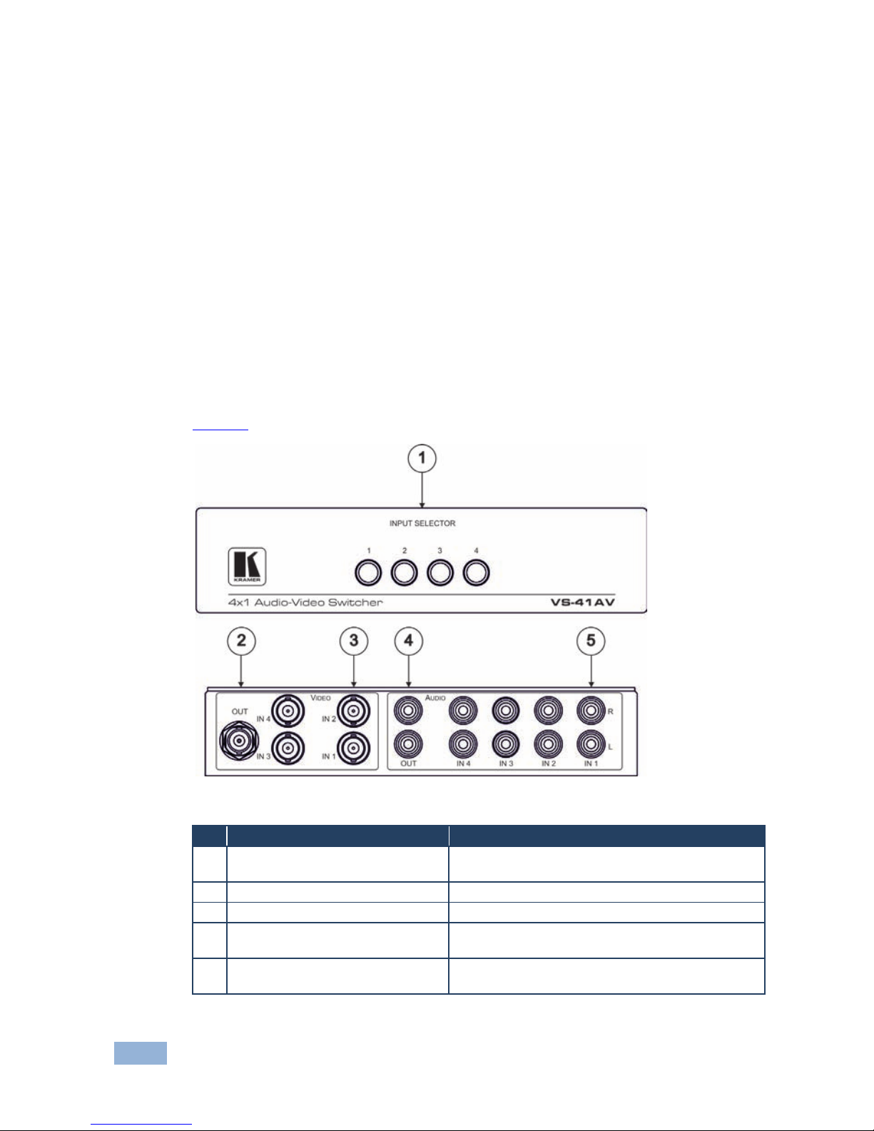
Figure 1 defines the VS-41AV.
Figure 1: VS-41AV 4x1 Audio-Video Switcher
# Feature Function
1 INPUT SELECTOR Buttons (1-4) Press to choose which input to switch to the
output
2 VIDEO OUT BNC Connector Connect to a composite video acceptor
3 VIDEO IN (1-4) RCA Connectors Connect to up to 4 composit e vi de o sources
4 AUDIO OUT RCA Connectors Connect the right and left channels to an
unbalanced ster eo au di o acce ptor
5 AUDIO IN (1-4) RCA Connectors Connect the right and left channels to up to 4
unbalanced stereo audio sources
Page 8
VS-41AV, VS101AV, VS-4X - Overview 5
3.2 Defining the VS-101AV 10x1 Video/Audio-Stereo
Switcher
The VS−101AV is a high−performance switcher for composite video and
unbalanced audio signals. It switches any one of 10 composite video and
unbalanced stereo audio signals to a single composite output.
The VS-101AV features:
• High bandwidth of 500MHz (-3dB)
• Mechanical (passive) switching that requires no power
• A standard 19” rack mount size of 1U.
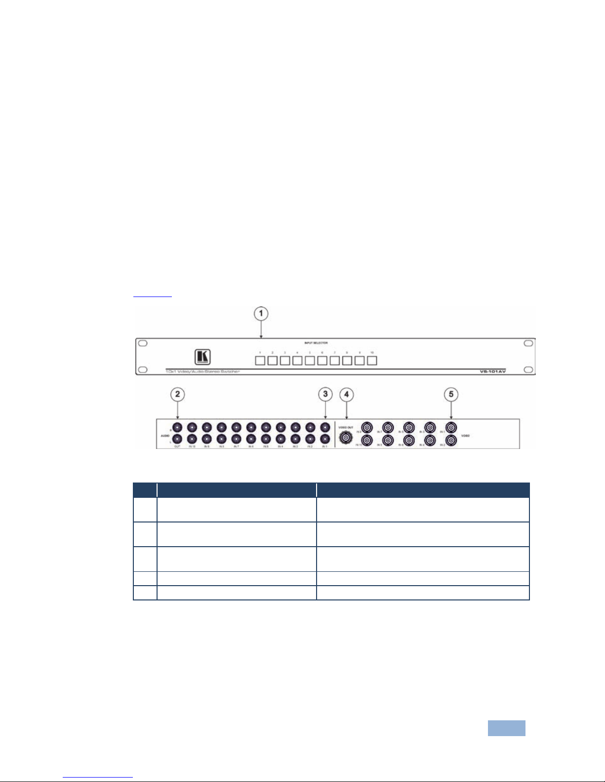
Figure 2 defines the VS-101AV.
Figure 2: VS-101AV 10x1 Video/Audio-Stereo Switcher
# Feature Function
1 INPUT SELECTOR Buttons (1-10) Press to choose which input to switch to the
output
2 AUDIO OUT RCA Connectors Connect the right and left channels to an
unbalanced ster eo au di o acce ptor
3 AUDIO IN (1-10) RCA Connectors Connect the right and left channels to up to 10
unbalanced stereo audio sources
4 VIDEO OUT BNC Connector Connect to a composite video acceptor
5 VIDEO IN (1-10) RCA Connectors C onn ect to up to 10 composite video sources
Page 9
6 VS-41AV, VS101AV, VS-4X - Overview
3.3 Defining the VS-4X 4x1 Balanced Audio Switcher
The VS−4X is a high−performance switcher for balanced stereo audio signals on
XLR connectors. It switches any one of four stereo signals to a single stereo
output.
• Mechanical (passive) switching that requires no power
• Compact desktop size. Two units can be rack mounted side-by-side in a 1U
rack space with the optional RK-4X adapter
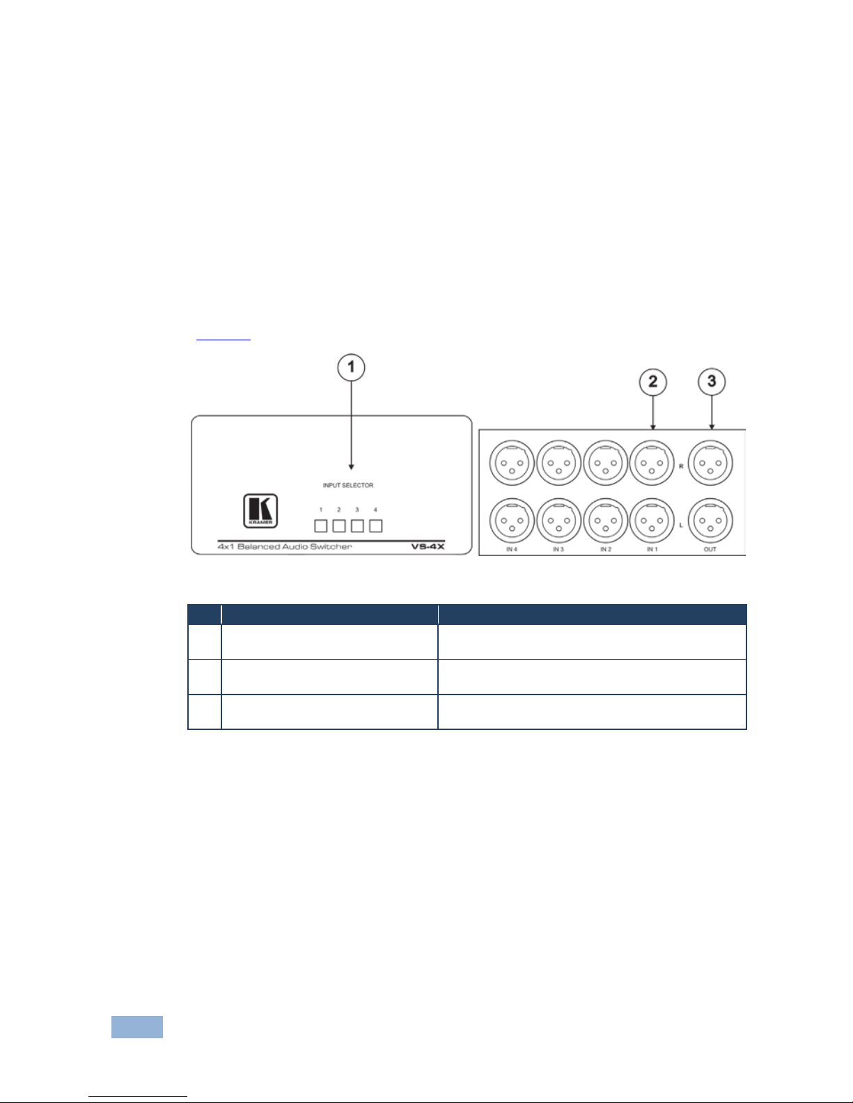
Figure 3 defines the VS-4X.
Figure 3: VS-4X 4x1 Balanced Audio Switcher
# Feature Function
1 INPUT SELECTOR Buttons (1-4) Press to choose which input to switch to the
output
2 IN (1-4) XLR Connectors Connect the right and left channels to up to 4
balanced stereo audio sources
3 OUT XLR Connectors Connect the right and left channels to a balanced
stereo audio acceptor
Page 10

VS-41AV, VS101AV, VS-4X - Connecting and Operating the Switchers 7
4 Connecting and Oper a t ing the Switchers
This section describes how to connect and operate the three mechanical Kramer
switchers:
• VS-41AV 4x1 Audio-Video Switc her (see Section 4.1)
• VS-101AV 10x1 Video/Audio-Stereo Switcher (see Section 4.2)
• VS-4X 4x1 Balanced Audio Switcher (see Section 4.3)
Page 11
8 VS-41AV, VS101AV, VS-4X - Connecting and Operating the Switchers
4.1 Connecting the VS-41AV 4x1 Audio-Video Switcher
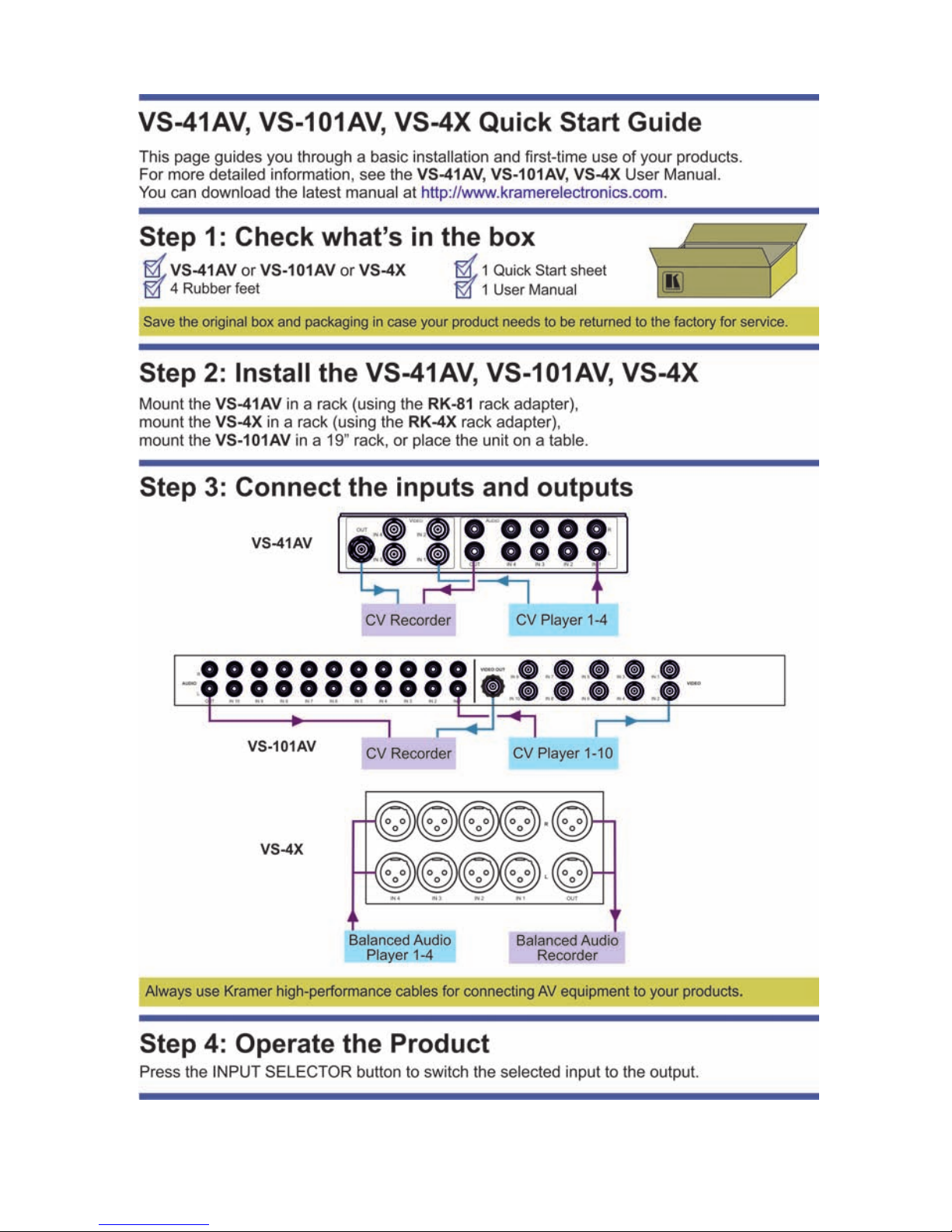
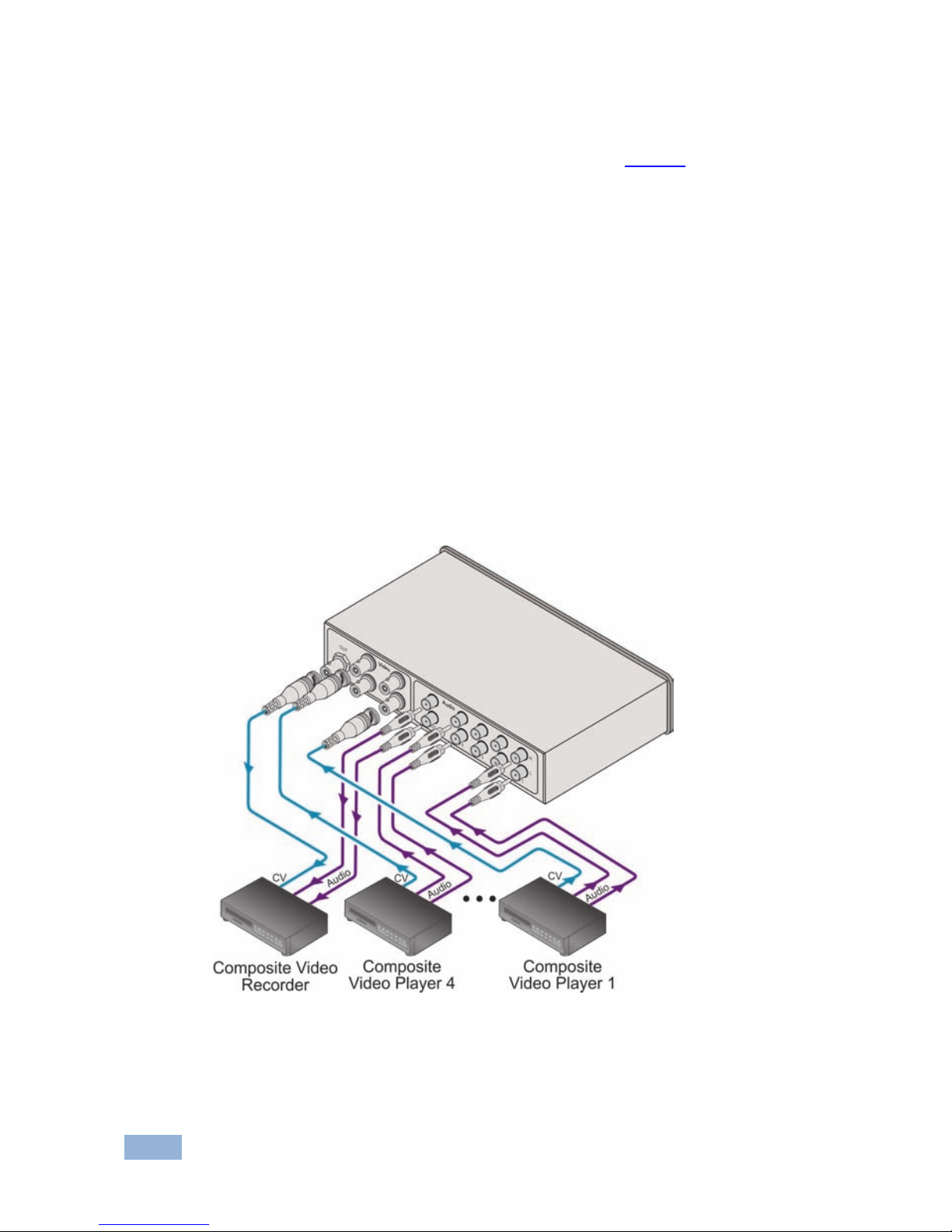
To connect the VS-41AV as illustrated in the exampl e in Figure 4:
1. Connect up to 4 CV sources (for example, composite video players 1-4) to
the VIDEO IN BNC connectors.
2. Connect up to 4 unbalanced stereo audio sources (for example, the audio
output from composite video players 1-4) to the right and left channels of the
AUDIO IN RCA connectors.
3. Connect the VIDEO OUT BNC connector to a CV acceptor (for example, a
composite video recorder).
4. Connect the right and left channels of the AUDIO OUT RCA connectors to
an audio acceptor (for example, the audio input to the composite video
recorder).
Figure 4: Connecting the VS-41AV
Page 12
VS-41AV, VS101AV, VS-4X - Connecting and Operating the Switchers 9
4.2 Connecting the VS-101AV 10x1 Video/Audio-Stereo
Switcher
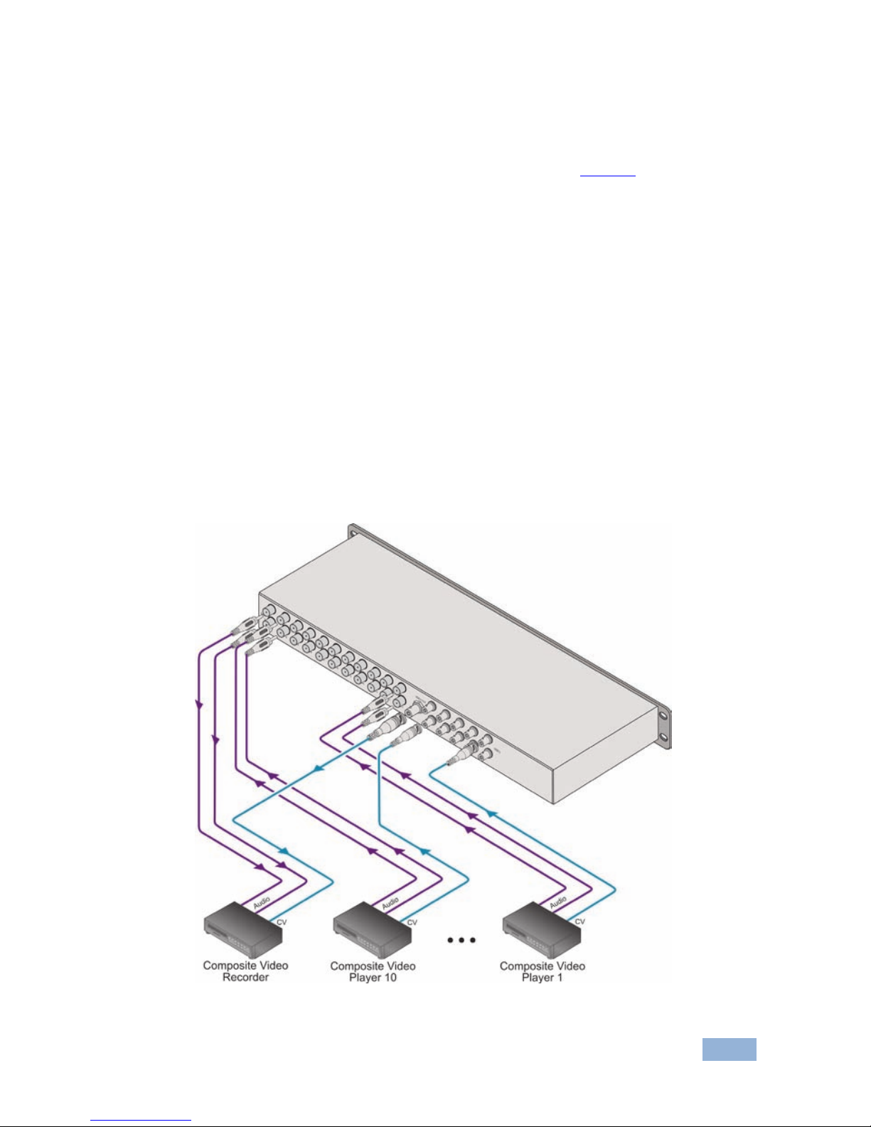
To connect the VS-101AV as illustrated in the example in Figure 5:
1. Connect up to 10 CV sources (for example, composite video players 1-10) to
the VIDEO IN BNC connectors.
2. Connect up to 10 unbalanced stereo audio sources (for example, the audio
output from composite video players 1-10) to the right and left channels of
the AUDIO IN RCA connectors.
3. Connect the VIDEO OUT BNC connector to a CV acceptor (for example, a
composite video recorder).
4. Connect the right and left channels of the AUDIO OUT RCA connectors to
an audio acceptor (for example, the audio input to the composite video
recorder).
Figure 5: Connectin g the VS-101AV
Page 13
10 VS-41AV, VS101AV, VS-4X - Connecting and Operating the Switchers
4.3 Connecting the VS-4X 4x1 Balanced Audio Switcher
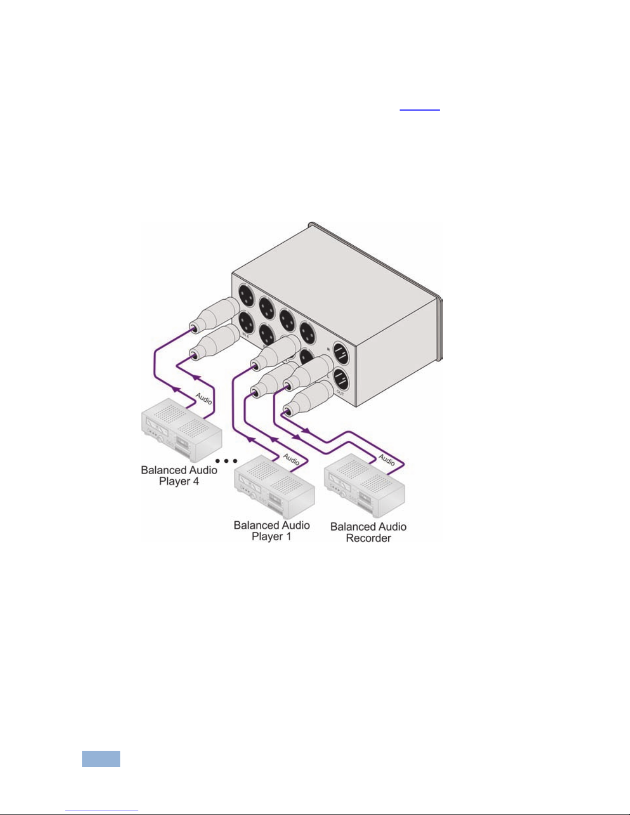
To connect the VS-4X as illustrated in the example in Figure 6:
1. Connect up to 4 balanced stereo audio sources (for example, balanced
audio players 1-4) to the right and left channels of the IN XLR connectors.
2. Connect the right and left channels of the OUT XLR connectors to an audio
acceptor (for example, a balanced stereo audio recorder).
Figure 6: Connecting the VS-4X
4.4 Operating the Switchers
To switch the desired input to the output, press the appropriate INPUT
SELECTOR button. In the VS-41AV or VS-101AV switchers, audio and video
inputs switch at the same time in audio-follow-video mode.
Page 14
VS-41AV, VS101AV, VS-4X - Technical Specifications 11
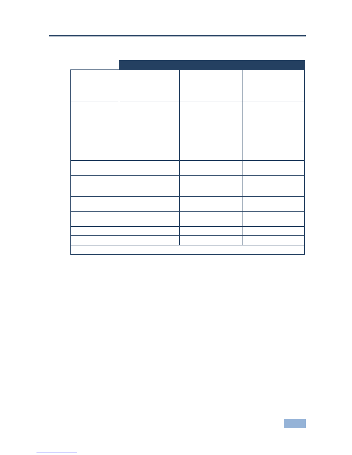
5 Technical Specifications
VS-41AV VS-101AV VS-4X
INPUTS: 4 video, 1Vpp/75Ω on
BNC connectors,
4 stereo audio, +4dBu
typical, on RCA
connectors
10 video, 1Vpp/75Ω on
BNC connectors,
10 unbalanced stereo
audio, +4dBu typical, on
RCA connectors
4 balanced stereo
audio, +4dBu typical, on
XLR connectors
OUTPUTS: 1 video, 1Vpp/75Ω on a
BNC connector,
1 stereo audio, +4dBu
typical, on an RCA
connector
1 video, 1Vpp/75Ω on a
BNC connector,
1 unbalanced stereo
audio, +4dBu typical, on
an RCA connector
1 balanced stereo
audio, +4dBu typical, on
an XLR connector
SWITCHING
SYSTEM:
Mechanical, "Breakbefore-make",
Audio- Follow-Video
mode
Mechanical, "Breakbefore-make",
Audio- Follow-Video
mode
Mechanical, "Breakbefore-make"
BANDWIDTH: Video: 520MHz (–3dB)
Audio: 100kHz (–3dB)
Video: 500MHz (–3dB)
Audio: 100kHz (–3dB)
Audio: 100kHz (–3dB)
CROSSPOINTS: 4 for video, 4x2 for
audio, 1 set active at
any given time
10 for video, 10x2 for
audio, 1 set active at any
given time
4x2 for stereo audio
SIGNAL LEVELS: Video: Up to 3Vpp
Audio: +30dBu
Video: Up to 3Vpp
Audio: +30dBu
Up to +30dBu
DIMENSIONS
(W, D, H):
18.8cmx10.2cmx4.4cm
(7.4" x 4" x 1.7")
48.3cmx10.2cmx4.4cm
(19" x 4" x 1U)
15.3cmx6.6cmx7.6cm
(6” x 2.6” x 3”)
WEIGHT: 0.65kg(1.44lbs) approx 1.5kg (3.3lbs) approx 0.57kg (1.27lbs) approx
OPTIONS: RK−81 19” rack adapter RK−4X 19" rack adapter
Specifications are subject to change without notice at http://www.kramerelectronics.com
Page 15
Page 16

For the latest information on our products and a list of Kramer distributors,
visit our Web site where updates to this user manual may be found.
We welcome your questions, comments, and feedback.
Web site:
www.kramerelectronics.com
E-mail: [email protected]
!
SAFETY WARNING
Disconnect the unit from the power
supply before opening and servicing
 Loading...