

Kramer VS-402XL, VS-602XL User Manual

Kramer Electronics, Ltd.
USER MANUAL
Models:
VS-402XL, 4x2 Vertical Interval Vid e o-Audio Matrix Switcher
VS-602XL, 6x2 Vertical Interval Vid e o-Audio Matrix Switcher

Contents
i
Contents
1 Introduction 1
2 Getting Starte d 1
2.1 Quick Start 1
3 Overview 3
4 Your Vertical Interval Video-Audio Matrix Switcher 3
5 Installing in a Rack 7
6 Connecting a Vertical Interval Video-Audio Matrix Switcher 8
6.1 Controlling via RS-232 (for example, using a PC) 10
6.2 Controlling via RS-485 11
6.3 Setting the DIP-switches 12
6.3.1 Setting the MACHINE # 12
6.4 Connecting the REMOTE Connector 13
6.5 Connecting the Balanced/U nbalance d Stereo Audio Input/Output 14
7 Cascading Vertical Interval Video-Audio Matrix Switchers 15
7.1 Cascading Units in an Input Expansion Configuration 15
7.2 Cascading a set of Units in a (RGB) Parallel Configuration 17
7.3 Cascading Individual Units in a Control Configuration 19
7.3.1 Control Configuration via RS-232 and RS-485 19
7.3.2 Control Configuration via RS-485 20
7.4 Looping Units in an Increased Output Configuration 22
8 Operating the Vertical Interval Video-Audio Matrix Switcher 22
8.1 Choosing the Audio-Follow-Video or Breakaway Option 23
8.1.1 Setting the Audio-Follow-Video Option 23
8.1.2 Setting the Breakaway Option 23
9 Technical Specifications 24
10 Table of Hex Codes for Serial Communication 25
11 Communication Protocol 26

KRAMER: SIMPLE CREATIVE TECHNOLOGY
Introduction
ii
Figures
Figure 1: Vertical Interval Video-Audio Matrix Switchers 4
Figure 2: VS-602XL Underside 6
Figure 3: Connecting the VS-402XL Vertical Interval Video-Audio Matrix Switcher 9
Figure 4: Connecting a PC without using a Null-modem Adapter 10
Figure 5: Controlling via RS-485 (for example, using an RC-3000) 11
Figure 6: DIP-switch Default Setup 12
Figure 7: Remote Connector PIN # Settings 13
Figure 8: Connecting a Balanced Stereo Audio Input/Output 14
Figure 9: Connecting an Unbalanced Stereo Audio Input 14
Figure 10: Connecting an Unbalanced Stereo Audio Output 14
Figure 11: Cascad ing Units in an Input Expansion Configuration 17
Figure 12: Cascad ing a set of three Units in a (RGB) Parallel Configuration 18
Figure 13: Cascading Individual Units in a Control Configur ation via RS-232 a nd RS-485 20
Figure 14: Cascad ing Individual Units in a Control Configuration via RS-485 21
Figure 15: Adding Outputs by Looping Units 22
Tables
Table 1: Verti cal Interval Video-Audio Matrix Switcher Features 5
Table 2: VS-602XL Underside Features 6
Table 3: DIP-switch Settings 12
Table 4: Machine # DIP-switch Settings 13
Table 5: Technical Specifications of the VS-402XL/VS-602XL 24
Table 6: VS-402XL/VS-602XL Hex Codes for Switching via RS-232/RS-485 25
Table 7: Protocol Definitions 26
Table 8: Instruction Codes 27

Introduction
1 1
1 Introduction
Welcome to Kramer Electronics! Since 1981, Kramer Electronics has been
providing a world of uni que, creat iv e, an d aff ordabl e s oluti ons to t h e vast range
of problems that confr ont th e video, audio, presentation, an d broadcas t ing
professional on a daily basis. In recent years, we have redesigned and upgraded
most of our line, making th e best ev en be tter! Our 1, 000-plus different models
now appear in 11 grou ps
1
Congratulations on purchasing your Kramer VS-402XL 4x2 Vertical Interval
Video-Audio Matrix S witcher and/or VS-602XL 6x2 Vertical Interval
Video-Audio Matrix S witcher.
that are clearly defined by function.
Your Kramer VS-402XL/VS-602XL is ideal for the following typical
applications:
• Live broadcast or presentation applications such as switching between
cameras in real-time
• CCTV, home theater
• Rental and staging applications
• Video production studios
The VS-402XL and/or the VS-602XL package include the following items:
• Vertical Interval Video-Audio Matrix Switcher
• Windows®-based control software
• Power cord, Null-modem adapter and this user manual
2
2 Getting Started
We recommend that you:
• Unpack the equipment ca refully and save the original box and packaging
materials for possible future shipment
• Review the contents of this use r manual
• Use Kramer high performance high resolution cables
3
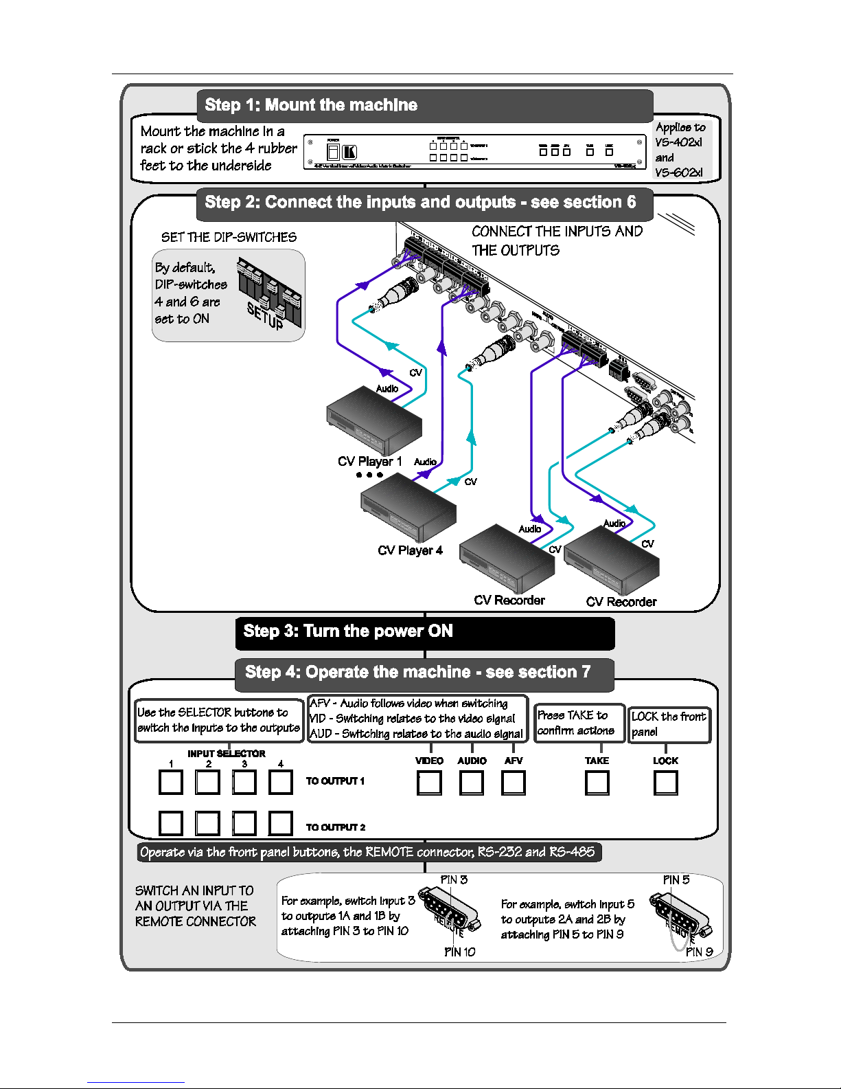
2.1 Quick Start
This quick start chart summarizes the basic setup and operation steps.
1 GROUP 1: Distribution Amplifiers; GROUP 2: Switchers and Matrix Switchers; GROUP 3: Control Syste ms; GROUP 4:
Format/Standards Converters; GROUP 5: Range Extenders and Repeaters; GROUP 6: Specialty AV Products; GROUP 7:
Scan Converters and Scalers; GROUP 8: Cables and Connectors; GROUP 9: Roo m Connectivity; GROUP 10: Accessories
and Rack Adapters; GROUP 11: Sierra Products
2 Download up-to-date Kramer user manuals from the Internet at
http://www.kramerelectronics.com
3 The complete list of Kramer cables is on our Web site at
http://www.kramerelectronics.com
KRAMER: SIMPLE CREATIVE TECHNOLOGY
Getting Started
2

Overview
3 3
3 Overview
The Kramer VS-602XL (a 6x2 switcher) and VS-402XL (a 4x2 switcher) are
high performance vertical interval matrix switchers for composite video and
stereo balanced audio signals. Both the VS-602XL and the VS-402XL feature:
• A video bandwidth that exceeds 300MHz, ensuring that they remai n
transparent even in the most critical ap plications
• LEVEL (gain) and EQ (peaking) contro ls for ea ch output
• Looping inputs
• Selectable input signal termination
• A TAKE button
1
• Two sets of INPUT SELECTOR buttons (one set for each o utput) and
five front panel control buttons
for precise switch control and a LOCK button to prevent
tampering with t he front panel
• Audio-follow-video or audio breakaway option
• Glitch-free trans iti on s , wh en s ou rces sh ar e a c omm on r ef eren ce sy nc
2
• Switching synchronization either to an external reference or the incoming
video
• Two duplicate
3
• Control via the front panel buttons; remotely by RS-485 or RS-232 serial
commands transmitted by a touch screen system, PC, or other serial
controller; and/or via contact closure switches
outputs per set of INPUT SELECTOR buttons (4 outputs
in total)
• Standard 1U 19” rack mount size, with rack "ears" included
To achieve the best performance:
• Connect only good quality connection cables, thus avoiding interference,
deterioration in signal q uality due to poor matching, and elevated noise
levels (often associated with low quality cables)
• Avoid interference from neighboring electrical appliances that may
adversely influe nce signa l quality and position your Kramer VS-402XL or
VS-602XL away from moisture, excessive sunlight and dust
4 Your Vertical Interval Video-Audio Matrix Switcher
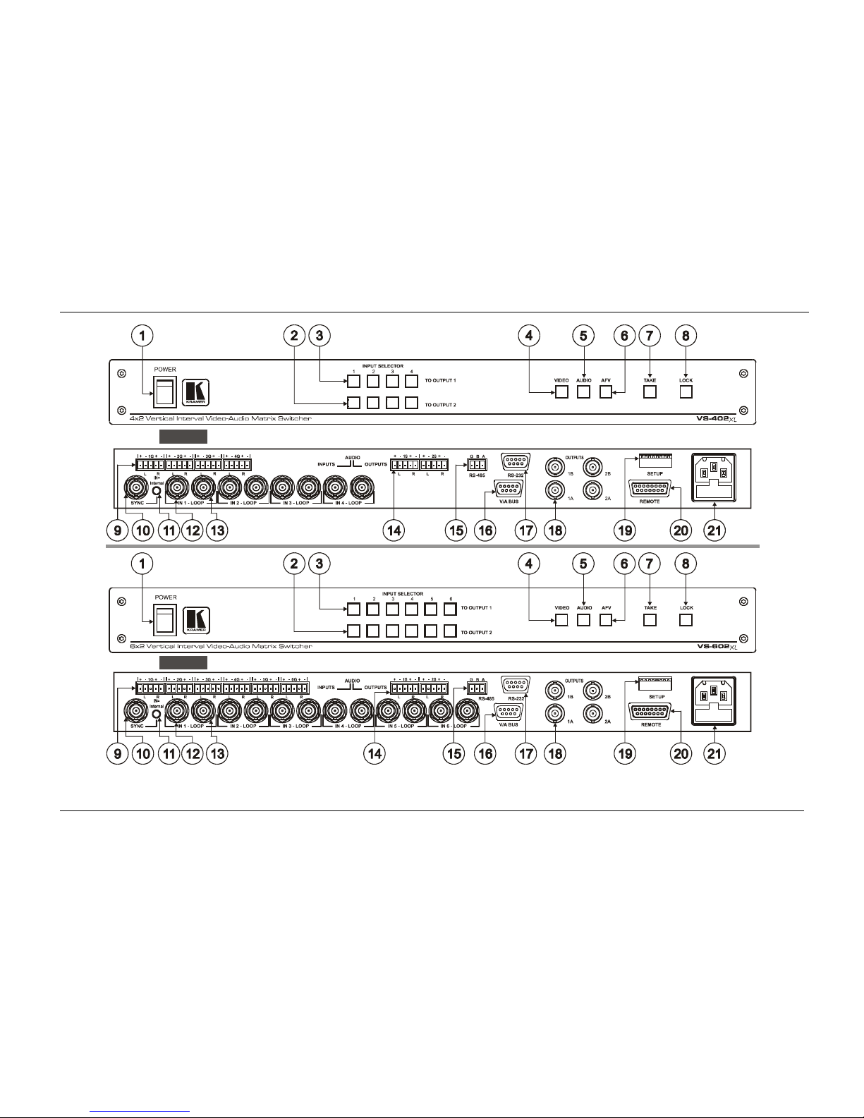
Figure 1 and Table 1 define the front and rear panels of the VS-402XL and
the VS-602XL.
1 Also enables the user to place multiple switc hes in a queue and t hen activate them with o ne touch of this button, or via a
single serial command
2 As it switches during the vertical interval
3 1A and 1B, 2A and 2B
KRAMER: SIMPLE CREATIVE TECHNOLOGY
Your Vertical Interval Video-Audio Matrix Switcher
4
VS-402xl
VS-406xl
Figure 1: Vertical Interval Video-Audio Matrix Swi tc he rs

Your Vertical Interval Video-Audio Matrix Switcher
5 5
Table 1: Vertical Interval Video-Audio Matr ix Sw i tc he r Features
# Feature Function
1 POWER Switch Illuminated switch for turning the unit ON or OFF
2 INPUT SELECTOR TO
OUTPUT 2
Buttons
1
Select the input to switch to OUTPUTS 2A and 2B
3 INPUT SELECTOR TO
OUTPUT 1 Buttons
1
Select the input to switch to OUTPUTS 1A and 1B
4 VIDEO Button
2
When pressed acti ons relate to video
5 AUDIO Button2 When pressed acti ons relate to audio
6 AFV Button
3
When pressed audio channels fol low the vid eo chan nels
7 TAKE Button Pressing TAKE toggles the mode between the CONFIRM mode
4
8
and the AT ONCE mode (user confirmation per action is
unnecessary)
LOCK Button Disengages the front panel switches
9 AUDIO INPUTS Terminal
Block Connectors
1
Connects the audio sources
10 SYNC BNC Connector Connects to the external SYNC source
11 SYNC Source Selector
(IN=Internal) Button
Pushing in selects internal sync5, releasing selects the external
sync
6
12
source
IN BNC Connectors1 Connects the composite video sources
13 LOOP BNC Connectors1 For looping to increase output availability
14 AUDIO OUTPUTS Terminal
Block Connectors
Connects the two audio acceptors
15 RS-485 Connector RS-485 detachable terminal block port
16 V/A BUS Connector 9-pin D-sub connector connects to the V/A BUS Connector on the
next unit(s) via a short DB9M flat cable when cascading in an input
expansion configuration
17 RS-232 Connector 9-pin D-sub connector connects to PC or other Serial Controller
18 OUTPUTS 1A; 2A; 1B; 2B
BNC Connectors
Connect to the output ac ce pto rs
19 SETUP DIP-switches for setup
20 REMOTE Connector Attach a specific PIN to PIN 9 or PIN 10 to switch an input via a
remote contact closure switch
7
6.4 (refer to section )
21 Power Connecto r wit h Fus e AC connector enabling power supply to the unit
1 Four on the VS-402XL; six on the VS-602XL
2 Refer to section
8.1.2
3 Refer to section
8.1.1
4 When in Confirm mode, the TAKE button illuminates
5 On the IN 1 connector
6 On the SYNC connector
7 The appropriate front panel INPUT SELECTOR button illuminates
KRAMER: SIMPLE CREATIVE TECHNOLOGY
Your Vertical Interval Video-Audio Matrix Switcher
6
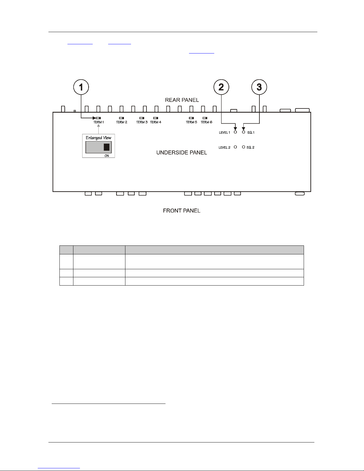
Figure 2 and Table 2 define the six TERM switches and the four trimmers on
the underside of the VS-602XL unit
1
Figure 2. shows to which LO OP
connector each TERM switch relates and the location of the trimmers for
adjusting OUTPUTS 1 and 2 and for adjusting EQ. 1 and EQ. 2.
POWER
POWER
Switch
REMOTEV/A BUS
LOCK
SYNC
INPUT SELECTOR
Figure 2: VS-602XL Underside
Table 2: VS-602XL Underside Features
# Feature Function
1 TERM Switch
Move to the right (ON position) to terminate with 75Ω, or move to the
left for looping
2
2 LEVEL Trimmers Adjusts
3
3
the output signal level for OUTPUTS 1 a nd 2
EQ. Trimmers Adjusts3 the equalization level ( EQ.) for OUTP UTS 1 and 2
1 The underside of the VS-402XL unit contains four TERM switches
2 The factory default
3 Insert a screwdriver into the small hole and carefully rotate it, trimming the OUTPUT level or EQ level
Installing in a R ack
7 7
5 Installing in a Rack
This section describes what to do before ins talling in a rack and how to rack
mount.
Before Installing in a Rack
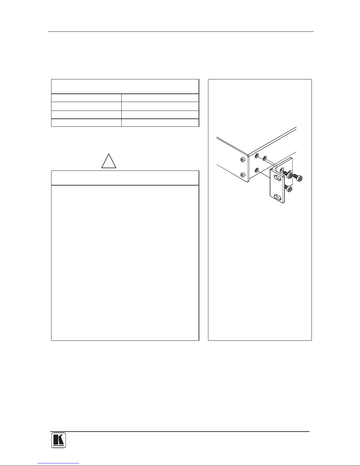
How to Rack Mount
Before installing in a rack, be sure that the environment is
within the recommended range:
To rack-mount a machine:
1. Attach both ear brackets to the
machine. To do so, remove the
screws from each side of the
machine (3 on each side), and
replace those screws through the
ear brackets.
2. Place the ears of the machine
against the rack rails, and insert the
proper screws (not provided)
through each of the four holes in the
rack ears.
Note that:
• In some models, the front panel
may feature built-in rack ears
• Detachable rack ears can be
removed for desktop use
• Always mount the machine in the
rack before you attach any cables
or connect the machine to the
power
• If you are using a Kramer rack
adapter kit (for a machine that is not
19"), see the Rack Adapters user
manual for installation instructions
(you can download it at:
http://www.kramerelectronics.com)
Operating temperature range
+5° to +45° C (41° to 113° F)
Operating humidity range 10 to 90% RHL, non-condensing
Storage temperature range
-20° to +70° C (-4° to 158° F)
Storage humidity range 5 to 95% RHL, non-condensing
!
CAUTION
!!
When installing in a 19" rack, avoid hazards by taking
care that:
1. It is located within the recommended environmental
conditions, as the op era ti ng ambi ent t e m pera tur e of a
closed or multi unit rack assembly may exceed the
room ambient temperature.
2. Once rack mounted, enough air will still flow around
the machine.
3. The machine is placed straight in the correct
horizontal positi on.
4. You do not overload the circuit(s). When connecting
the machine to the supply circuit, overloading the
circuits might have a detrimental effect on overcurrent
protection and supply wiring. Refer to the appro pri ate
nameplate ratings for information. For example, for
fuse replacemen t, s ee the value printed on the
product label.
5. The machine is earthed (grounded) in a reliable way
and is connected onl y to an ele ctric ity socket with
grounding. Pay particular attention to situations where
electricity is supplied indirectly (when the power cord
is not plugged directly into the socket in the wall), for
example, when using an extension cable or a power
strip, and that you use only the power cord that is
supplied with the machine.
 Loading...