

Page 1
AI2 SYNTHESIS MODULE
GENERAL
INSTRUMENT
Owner’s Manual
AI2 Synthesis System
1E
Page 2

Introduction
Features of the X5DR
Superior Sound with Korg's AI2 Synthesis System
The Korg X5DR employs Korg's AI2 Synthesis System for all digital processing. From the tone
generator—with its 8MB capacity—to the filters, amplifier, and effect units, all audio is handled
in the digital domain, which ensures the highest quality sound with absolutely no signal loss or
deterioration in audio quality.
2
Based on state-of-the-art PCM technology, the AI
Korg to capture the true essence of acoustic sound for use in a tone generator. Since its
introduction in Korg's 01/W series, X2/X3/X5, and i2/i3 synthesizers, the AI
has received unqualified praise from musicians and artists throughout the world. W ith the X5DR,
you will enjoy a richness and variety of sound at a level of excellence that meets or exceeds the
quality of audio CDs.
Multisounds Let You Create an Endless Variety of Sounds
The X5DR contains 430 built-in Multisounds, which are multi-sampled PCM waveforms. These
Multisounds allow you to simulate a range of acoustic sounds, from drums and percussion to
piano, guitar, and trumpet. The X5DR also features unique Multisounds—such as Synth and
Special Effects—which provide a wide variety of flexible tools for sound creation. In fact, the
X5DR can generate a virtually endless variety of sounds.
These built-in Multisounds can be played in their unmodified form. They can also be modified to
create the sound of various musical instruments once they pass through a powerful VDF (filter)
and VDA (amplifier). You can also add a rich expressiveness to a performance by altering the
sound using the key touch velocity, or by adjusting the brightness of the sound or the depth of the
vibrato using MIDI modulation messages.
Synthesis System is technology developed by
Introduction
2
Synthesis System
Rich, large-scale ensembles with 64-voice polyphony
The X5DR's 64-voice polyphonic capability allows you to create complex ensemble and
large-scale orchestral sounds. Combinations of multiple Programs and features in Multi mode will
help you achieve such effects. The X5DR can simulate a magnificent piano sound, replete with a
damper pedal, and ensembles of various instrumental parts without any notes cutting off.
236 Programs in Banks A and G
Bank A contains 100 Programs and Bank G contains 136 General MIDI (GM) compatible
Programs. You can store your own Programs in Bank A.
Programs comprise the basic sounds of the X5DR. You can play different Programs in a song; you
can even layer them in Combinations.
One Hundred Combination Slots Allow for an Endless Variety of Programs
Up to 100 Combinations can be stored in the X5DR. Up to eight Programs can be assigned to each
Combination. In Combinations, you can layer or split multiple Programs by setting the Key
Window or Velocity Window parameters.
Combinations are powerful sound tools, especially for live performance. The Combination types
layer, split
, and
velocity switch
provide various sound structures.
Drum Kits Support a Variety of Rhythms
The X5DR provides 215 types of popular drum sounds, including both standard drum and
percussion sounds. You can create two Drum Kits by assigning different drum sounds to each ke y
on the keyboard. There are also eight ROM Drum Kits available.
i
Page 3

Introduction
A Drum Kit supports the rhythm of a song. Assigning a different drum sound to each key allows
you to create a wide variety of rhythm parts. Y ou can also edit the drum sounds using VDF, VD A,
and effect units.
Extensive Presets Produce a Wide Range of Truly Practical Sounds
The X5DR utilizes various Programs, Combinations, and Drum Kits as Preset data. Y ou can load
the sounds stored in Presets a and b into the Program or Combination memory for immediate use.
The Preset Load operation loads data from all preset sounds to one particular sound slot.
The versatile editing functions of the X5DR let you create original sounds very easily . On the other
hand, it is quite a bit of work to create a good sound from scratch. Given such circumstances,
Preset data can be very handy . Y ou can use the data immediately after you load a sound, choosing
from a broad selection. You can use Preset data just as it is, without modification. You can also use
Preset data as the raw material for sound editing. You may be able to glean a few ideas for
sound-making from the Preset sounds.
Digital Multi-Effects Processors: To Create and Add Dimension to Sounds
The X5DR contains two independent digital multi-effects processors that can produce various
effects such as reverb, delay, EQ, distortion rotary speaker, etc. These ef fects are very useful when
you want to create a new sound or add dimension to a sound. Some effects are actually a
combination of two effects. Using the X5DR's two independent digital multi-effects processors,
you can use up to four independent effects simultaneously.
The effects processors allow you to apply effects and edit the sounds directly on the X5DR,
instead of connecting external effect units. Placement settings are useful for processing the sound
and adding width or depth to the sound. Each Program and Combination can have its own effect
settings.
A wide range of scale types accommodates numerous musical genres
In addition to the conventional equal temperament and pure temperament types of tuning, a wide
variety of scales is also av ailable. These scales include the Werkmeister III, Kirnberger III, Arabic,
and Indonesian scales. These scales cover a broad range of musical genres, from classical to
various ethnic music, and prove e xtremely useful in the creation of realistic simulations of various
instruments.
W estern music generally uses a twelve-tone equal temperament that allo ws you to play in any ke y
and to transpose the key easily. However, the X5DR provides various scale types that will make
the sound of chords and the flow of phrases more beautiful, and which will allow you to perform
music utilizing temperaments other than the equal temperament, including the very complex and
subtle temperaments used in many ethnic musical pieces.
Multi Mode for GM
Since the X5DR conforms to the GM (General MIDI) standard in Multi mode, it can function as
a tone generator for computer music. It can also play GM songs (performance data designed for a
GM tone generator). Using original Programs in Bank A, or utilizing Key Window and Velocity
Window parameters, you can perform high-quality ensemble pieces.
The X5DR can be used as a GM tone generator with standard specifications. Y ou can also combine
different Programs and play original Programs via computer.
Equipped with a personal computer interface
The built-in computer interface enables a direct connection to the serial port of your personal
computer (Apple Macintosh or IBM-PC compatible).
You can connect the X5DR to a computer through either a MIDI connection using a MIDI
interface, or through a direct connection using a serial cable. Using the Korg MIDI Driver will
allow you to control data transmission from MIDI OUT independently of the X5DR tone
generator, or to simultaneously control an external MIDI device.
ii
Page 4
Controls
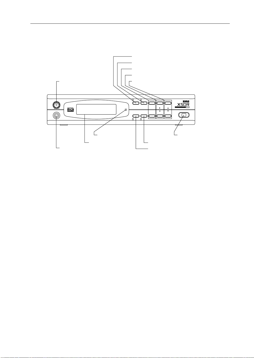
Front Panel
VOLUME
PHONES
1 VOLUME
100
B PHONES jack
A LCD display
2 [COMBI] button
3 [PROG] button
4 [BANK]/[PAGE+] button, [PAGE–] button
5 [+10]/[¤] button, [–10]/[ˆ] button
6 [+1]/[ £] button, [–1]/[ ¥] button
MIDI
COMBI PROG BANK
EDIT GLOBAL
MULTI
PAGE+
PAGE-
+10 +1
-10 -1
POWER
9 Power switch @ MIDI indicator
7 [GLOBAL]/[MULTI] button
8 [EDIT] button
Controls
About Color Codes for Letters and Numbers on the Keys:
White letters and numbers are used to select the Program/Combination numbers in Program Play mode and
Combination Play mode. Blue letters and numbers are used to edit and set up parameters in other modes.
1 VOLUME
This VOLUME knob is used to adjust the entire volume level. (That is, it simultaneously adjusts
the volume at the OUTPUT connector on the rear panel and the volume at the PHONES jack.)
2 [COMBI] button
Press this button to select the Combination Play mode. Pressing this button repeatedly will toggle
the displays for Timbres 1–4 and Timbres 5–8.
3 [PROG] button
Press this button to select the Program Play mode.
4 [BANK]/[PAGE+] button, [PAGE–] button
Repeatedly pressing the [BANK] button in Program Play mode will toggle between Bank A and
Bank G.
Pressing this button in Program Edit mode, Combination Edit mode, Multi mode, or Global mode
will change the page shown on the LCD. Press the [PAGE+] button to select the next page; press
the [PAGE–] button to select the previous page.
5 [+10]/[®] button, [–10]/[√] button
The [+10] and [–10] buttons increment and decrement the Program and Combination numbers in
steps of 10 in Program Play mode and Combination Play mode.
In Program Edit mode, Combination Edit mode, Multi mode, and Global mode, the [®] and [
buttons allow you to move the flashing cursor around the LCD to select parameters. When one
display page includes multiple LCD screens, you can switch screens by moving the cursor.
]
√
iii
Page 5

Controls
6 [+1]/[▲] button, [–1]/[▼] button
In Program Play mode and Combination Play mode, pressing the [+1] and [–1] buttons increment
and decrement the Program and Combination numbers in steps of 1.
In Program Edit mode, Combination Edit mode, Multi mode, and Global mode, these buttons can
be used to increase and decrease the currently-selected parameter value. In these modes, pressing
one of these buttons while pressing and holding down the [
parameter value very quickly.
These buttons are also used when the X5DR requires a yes or no answer from you on the LCD
screen. When the message “-- OK?” appears, press the [
to cancel.
7 [GLOBAL]/[MULTI] button
Press this button to enter Multi mode or Global mode. This button also switches the mode between
Multi mode and Global mode. In Multi mode, the indicator lights up; in Global mode, the indicator
flashes.
8 [EDIT] button
In Program Play mode, press this button to select the Program Edit mode. In Combination Play
mode, press this button to select the Combination Edit mode.
9 Power switch
This switch is used to power on and power off the X5DR.
0 MIDI indicator
This indicator lights up when the X5DR receives MIDI data via the MIDI IN jack or the T O HOST
jack.
] or [▼] button will change the
▲
] button to continue, or the [▼] button
▲
A LCD
This visual interface displays the current Program name and Combination name in Program Play
mode and Combination Play mode, respectively. In other modes, it displays parameters.
B PHONES jack
Connect the headphones to this stereo mini jack.
iv
Page 6

Rear Panel
1
DC IN
2
MIDI (IN, OUT, THRU)
Rear Panel
DC IN 12V
700mA
TO HOST THRU OUT
4
TO HOST
MIDI
IN
OUTPUT
R L/MONO
3
OUTPUT (L/MONO, R)
1 DC IN
Connect the AC adapter here.
Note:
Do not use adapters other than the AC adapter that comes with the X5DR! Otherwise, a
malfunction may occur.
2 MIDI (IN, OUT, THRU)
These connections are used to connect external MIDI instruments. MIDI IN receives MIDI data
from an external MIDI instrument. MIDI OUT outputs MIDI data from the X5DR to a connected
MIDI instrument. MIDI THRU outputs MIDI data received at the MIDI IN connection.
3 OUTPUT (L/MONO, R)
These 1/4 inch phone jack connections should be connected to the inputs of a powered monitor,
stereo amplifier, mixer, or multi-track tape recorder. Use the L/MONO connection for mono
playback.
4 TO HOST
This connection is used to connect a computer to the X5DR via an optional cable
(AG-001/002/003). This enables you to play the X5DR via a connected computer.
v
Page 7

Controls
vi
Page 8

Table of Contents
Table of Contents
Introduction
Features of the X5DR ..................................................................................................... i
Controls ........................................................................................................................iii
Front Panel ...................................................................................................................iii
Rear Panel .....................................................................................................................v
Table of Contents ........................................................................................................vii
About this manual .......................................................................................................xii
...................................................................................................................... i
Start-up Guide
Using a Keyboard
Connections ................................................................................................................... 1
MIDI Keyboard Settings ...............................................................................................2
Listening to a Demo performance.................................................................................. 3
Playing Programs .......................................................................................................... 4
If No Sound is Produced: .................................................................................... 5
Program Examples .............................................................................................. 5
Playing Combinations ................................................................................................... 7
Combination Examples ....................................................................................... 8
Using a Computer/Sequencer
Connections ................................................................................................................... 9
Connecting a computer or sequencer ................................................................ 10
Connection via MIDI ........................................................................................ 11
Connecting an IBM PC (Compatible) Computer .............................................. 12
Connecting an Apple Macintosh Computer ...................................................... 13
Settings Required When a Computer is Connected .......................................... 14
Listening to a Demo performance................................................................................ 15
Playing the X5DR in Multi Mode (Playing Back GM Scores).................................... 16
Structure of Multi Mode ................................................................................... 17
Selecting a Track Program From a Computer or Sequencer ............................ 17
Performance settings ......................................................................................... 18
Notes on Playing Back GM Scores ................................................................... 18
If You Cannot Play the X5DR .......................................................................... 19
Loading Preset Data .................................................................................................... 20
vii
Page 9

Table of Contents
Basic Guide
1. X5DR Modes
2. Performance Techniques
Program Play mode .....................................................................................................21
Playing Programs .............................................................................................. 21
Basic operation in Program Play mode ............................................................. 21
Program Edit Mode .....................................................................................................23
Basic operation in Program Edit mode .............................................................23
Combination Play Mode .............................................................................................. 24
Playing Combinations ....................................................................................... 24
Basic operation in Combination Play mode. ..................................................... 24
Combination Types ........................................................................................... 25
Combination Edit mode ...............................................................................................26
Basic operation in Combination Edit mode ......................................................26
Multi Mode .................................................................................................................. 27
Playing the X5DR in Multi mode .....................................................................27
Basic operation in Multi mode .......................................................................... 27
Global Mode ................................................................................................................ 29
Basic operation in Global mode ........................................................................ 29
Structure of the X5DR ................................................................................................. 30
Control via MIDI/Sequencer ............................................................................. 30
Signal flow in various modes ............................................................................ 31
Received MIDI data .......................................................................................... 32
Performance Functions ................................................................................................ 34
Keyboard Velocity ............................................................................................34
Pitch Bend/Modulation Wheel .......................................................................... 34
Effect Dynamic Modulation .............................................................................. 35
After Touch ....................................................................................................... 35
3. Editing
Basic Concepts ............................................................................................................36
Sound Structure ................................................................................................. 36
EG and MG ....................................................................................................... 37
Editing Programs......................................................................................................... 38
Before Editing ................................................................................................... 38
Checking the Sound While Editing ................................................................... 39
Adjusting the Attack of Programs ..................................................................... 40
Adjusting the Decay .......................................................................................... 41
Adjusting the Release ........................................................................................ 42
Adjusting the Tonal Brightness ......................................................................... 42
Editing a Multisound (Basic Waveform) .......................................................... 44
Adjusting Modulation .......................................................................................44
Adjusting the Panpot ......................................................................................... 45
About Double Mode .......................................................................................... 45
Some Hints for Editing Programs ..................................................................... 46
Editing Effects .............................................................................................................47
Effect Types ......................................................................................................47
Effects and Sound Level ...................................................................................50
Editing Combinations.................................................................................................. 51
Layering Multiple Programs .............................................................................51
Adjusting the Volume ....................................................................................... 52
Adjusting the Key Window ............................................................................... 52
Adjusting the Velocity Window ....................................................................... 52
More About Combination Edit ......................................................................... 52
Editing a Drum Kit ...................................................................................................... 53
viii
Page 10

Table of Contents
Preparing to Play a Drum Kit ............................................................................ 53
Editing a Drum Kit ............................................................................................ 53
Creating a Drum Program Using a ROM Drum Kit ......................................... 56
4. Application Guide
General Troubleshooting ............................................................................................. 57
Nothing is displayed on the LCD when the power switch is turned on. ..... 57
The X5DR does not produce any sound. ..................................................... 57
The sound does not stop. ............................................................................. 57
The X5DR does not respond to incoming MIDI data. ................................. 57
You cannot change Programs or Combinations. ......................................... 58
The wrong sounds are produced. ................................................................. 58
You cannot write a Program or Combination. ............................................. 58
You cannot select the parameter pages for OSC2 (e.g., VDF2 and VDA 2). 58
The X5DR does not play the specified drum sounds. ................................. 58
The X5DR does not play GM-compatible song data correctly. .................. 58
The X5DR doesn’t transmit MIDI Exclusive messages. ............................. 59
Performance Applications ........................................................................................... 60
Tuning the X5DR to Other Musical Instruments ........................................ 60
Changing the Key Velocity Sensitivity ....................................................... 60
Changing the Note Range ............................................................................ 60
Adjusting Effects while Playing .................................................................. 60
Changing the Sequence of Programs or Combinations ............................... 60
Combining Multiple Programs .................................................................... 60
Changing the Controller Functions in Combinations .................................. 61
Playing the Keyboard in Split Mode ........................................................... 61
Selecting a Particular Sound Quickly .......................................................... 61
Using a Different Scale ................................................................................ 61
Editing Applications .................................................................................................... 62
Editing the Sounds ....................................................................................... 62
Copying Effect Settings ............................................................................... 62
Editing the Sound from a Computer ............................................................ 62
Restoring the Parameter Values to the Factory Settings ............................. 62
Saving Sound Data ...................................................................................... 62
MIDI Applications ...................................................................................................... 63
Playing Multiple parts from a Sequencer .................................................... 63
Creating a GM Song .................................................................................... 63
Using Two X5DR’s (Using 128 Voices) ..................................................... 63
Convenient Functions .................................................................................................. 64
Page Memory ............................................................................................... 64
]/[▼] buttons ........................................................................................... 64
[
▲
5. About MIDI
What is MIDI? ............................................................................................................. 65
MIDI Connectors .............................................................................................. 65
MIDI Channel ................................................................................................... 65
MIDI Information ........................................................................................................ 66
Channel Message .............................................................................................. 66
Note On/Off ................................................................................................. 66
Program Change .......................................................................................... 66
Pitch Bend .................................................................................................... 67
After Touch .................................................................................................. 67
Control Change ............................................................................................ 68
System Messages .............................................................................................. 73
System Exclusive messages ......................................................................... 73
About the MIDI Filter ................................................................................................. 75
ix
Page 11

Table of Contents
Reference Guide
Parameter Guide
1. Program Parameters
2. COMBINATION Parameters
3. Multi Setup Parameters
4. Effect Parameters
5. Global Parameters
Appendix
About this chapter ....................................................................................................... 77
Functions in Program Mode ........................................................................................ 78
Functions in COMBINATION mode ........................................................................ 100
Multi Setup Functions ...............................................................................................107
Effect Parameter ........................................................................................................ 115
Functions in Global Mode .........................................................................................146
General Error Messages ............................................................................................ 161
Program Edit Mode & Combination Edit Mode Error Messages .............................161
Specifications ............................................................................................................ 161
Options ...................................................................................................................... 161
MIDI Data Format ..................................................................................................... 163
Program Change and Bank Select Reception in Combination Play Mode ............... 172
PC Interface Technical Information Chart ................................................................ 172
MIDI Panpot, Send Data ...........................................................................................173
Wiring Diagram of Dedicated Connecting Cables .................................................... 173
Installing and Setting Up the KORG MIDI Driver ................................................... 174
Installing the KORG MIDI Driver in MS Windows .................................................174
Setting Up the KORG MIDI Driver (Windows) ....................................................... 176
Installing the KORG MIDI Driver on a Macintosh Computer ................................. 177
Setting Up the KORG MIDI Driver for the Macintosh .............................................178
MIDI File Translator .................................................................................................179
MIDI Implementation Chart ...................................................................................... 180
INDEX........................................................................................................................182
Voice Name List ........................................................................................................ 185
x
Page 12
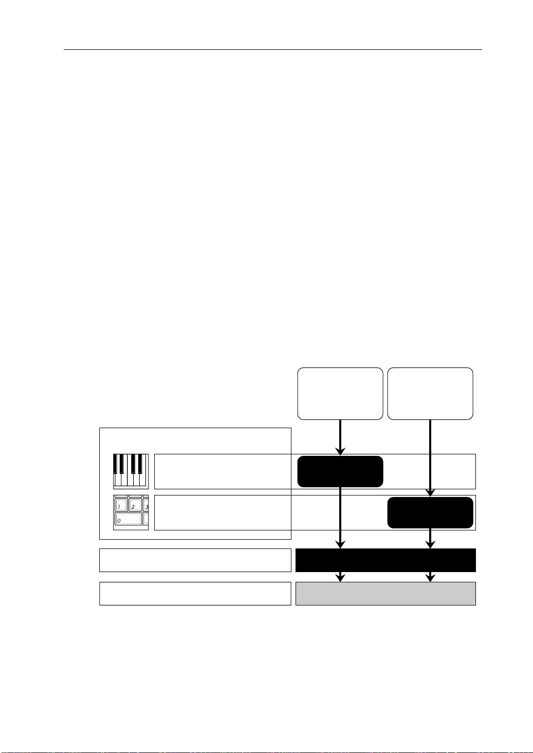
About this manual
This manual consists of the following chapters to enable you to extract information relevant to
your environment and applications.
Start-up Guide
This chapter explains the set-up procedure and basic operation of the X5DR. This chapter is
divided into two sections: “Using a Keyboard” and “Using a Computer/Sequencer.” Read the
“Using a Keyboard” section if you use the X5DR as an extended tone generator for your MIDI
keyboard. Read the “Using a Computer/Sequencer" section if you use a computer music system
or MIDI sequencer.
Basic Guide
This chapter explains the X5DR's configuration and modes. Read this chapter after you have
mastered the basic operations described in the Start-up Guide. This chapter also explains how to
edit Programs to create new sounds. Refer to this chapter to make the best use of the versatile
functions and various sounds of the X5DR.
Reference Guide
This chapter explains the function of each mode and the parameters of the X5DR in detail.
<<About MIDI>>
This manual assumes that you have a basic knowledge of MIDI. If you are using a synthesizer or
a MIDI device for the first time, read the section entitled “5. About MIDI” in the Basic Guide.
About this manual
Using the X5DR as
an extended tone
generator for a MIDI
keyboard:
Start-up Guide
Using a Keyboard
Using a Computer/Sequencer
Basic Guide
Reference Guide
Note:
The Program, Combination, and Multi T rack Pr ogram names shown on the LCD screen in
this manual are assumed names, and do not necessarily match the names found on the X5DR.
1
Using the X5DR
with a computer
music system or
sequencer:
1
22
33
xi
Page 13

About this manual
xii
Page 14
Start-up Guide
Using a
Keyboard
Start-up Guide
Using a Keyboard
Start-up Guide
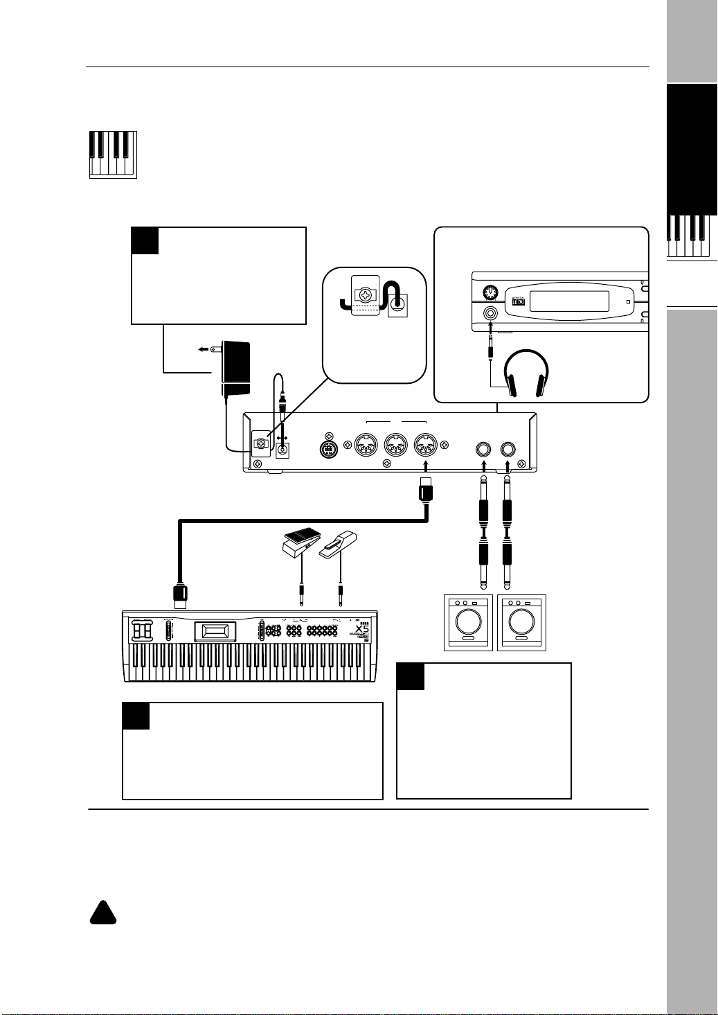
Connections
Connecting to a power source
1
Connect the AC adapter plug
to the DC IN connector on the
rear panel. Then, plug the AC
adapter into an AC outlet.
To the power outlet
AC Adapter
Volume pedal
DC IN
DC IN 12V
700mA
MIDI cable
Secure the AC adapter
cable by hooking it as
shown in the illustration to
prevent the adapter plug
from being accidentally
removed.
TO HOST THRU OUT
MIDI
Damper pedal
To use the headphones, plug the
headphone cable into the PHONES jack
on the front panel.
VOLUME
100
PHONES
PHONES
Headphones
IN
R
OUTPUT
R L/MONO
L/MONO
Start-up Guide
Using a
Keyboard
COM
MIDI
EDI
MIDI OUT
MIDI keyboard
Connecting a MIDI keyboard
3
Connect the MIDI OUT jack of the MIDI
keyboard to the MIDI IN jack of the X5DR
using a MIDI cable.
Connecting a monitor
2
Connect the OUTPUT jacks to
a powered monitor or stereo
amplifier.
* Use the L/MONO jack for
monaural connection.
Powered monitor
(such as the PM-15)
* Refer to “MIDI keyboard settings” (page 2).
Powered monitor/stereo amplifier
In order to playback the X5DR's high-fidelity sound, we recommend that you connect the X5DR to
powered monitors (i.e., speakers with built-in amplifiers, such as the optional PM-15). If you are going
to connect a stereo amplifier or other device (such as a stereo radio or a cassette tape recorder), use
the connector labeled “LINE IN” or “AUX IN” on those devices.
If you connect the X5DR to a domestic hi-fi system, be careful not to raise the volume level too
!
high, or you may damage the speakers.
1
Page 15

Start-up Guide
MIDI Keyboard Settings
Use the following MIDI keyboard transmit settings before you play the X5DR from a connected
keyboard. Refer to the MIDI keyboard manual for detailed settings.
•
The X5DR is a MIDI tone module that receives MIDI data sent from external MIDI devices
(such as a MIDI keyboard, computer, or sequencer) to playback data. Refer to the section
“Using a Computer/Sequencer” on page 9 for details when you wish to play the X5DR from a
connected computer or sequencer.
MIDI transmit channel
Set the MIDI keyboard transmit channel to “1.” If you wish to use a different MIDI transmit
channel on the MIDI keyboard, you must change the MIDI receive channel on the X5DR
accordingly.
•
If you cannot change the MIDI keyboard transmit channel (in other words, if its MIDI channel
is fixed), set the Global MIDI Channel on the X5DR to the same number as the MIDI transmit
channel on the MIDI keyboard.
MIDI transmit filter
MIDI keyboards allow you to transmit various MIDI data.
The X5DR can receive the following MIDI messages:
●
Note On/Off (Note message) --- Very basic message for keyboard performance.
●
Program Change message --- Changes Programs.
●
Control Change --- Controller and performance mode message.
●
Pitch Bend --- Bender (joystick, wheel, lever) pitch variation message.
●
After Touch (Channel Pressure) --- Information about pressing the keys after a note has been
struck.
•
Not all MIDI keyboards can transmit the MIDI messages listed above. When you are playing
the X5DR, it will receive only MIDI data that can be sent from a connected MIDI keyboard.
For example, if you are using a MIDI keyboard that does not transmit Pitch Bend messages
(such as a digital piano), you cannot achieve a pitch bend effect.
2
Page 16
Listening to a Demo performance
Start-up Guide
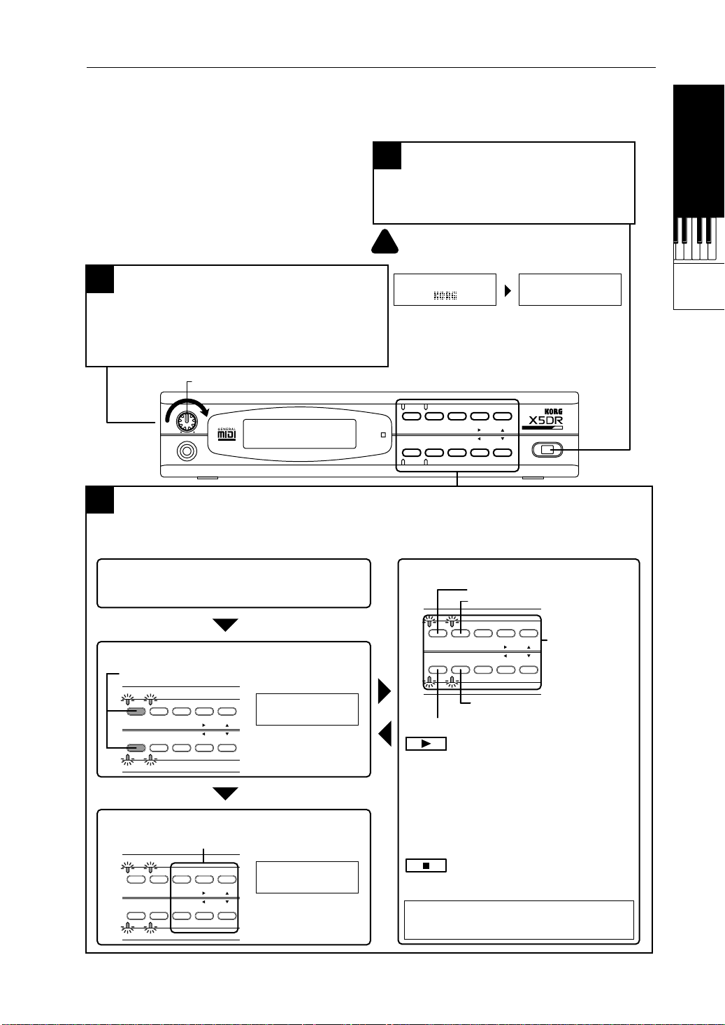
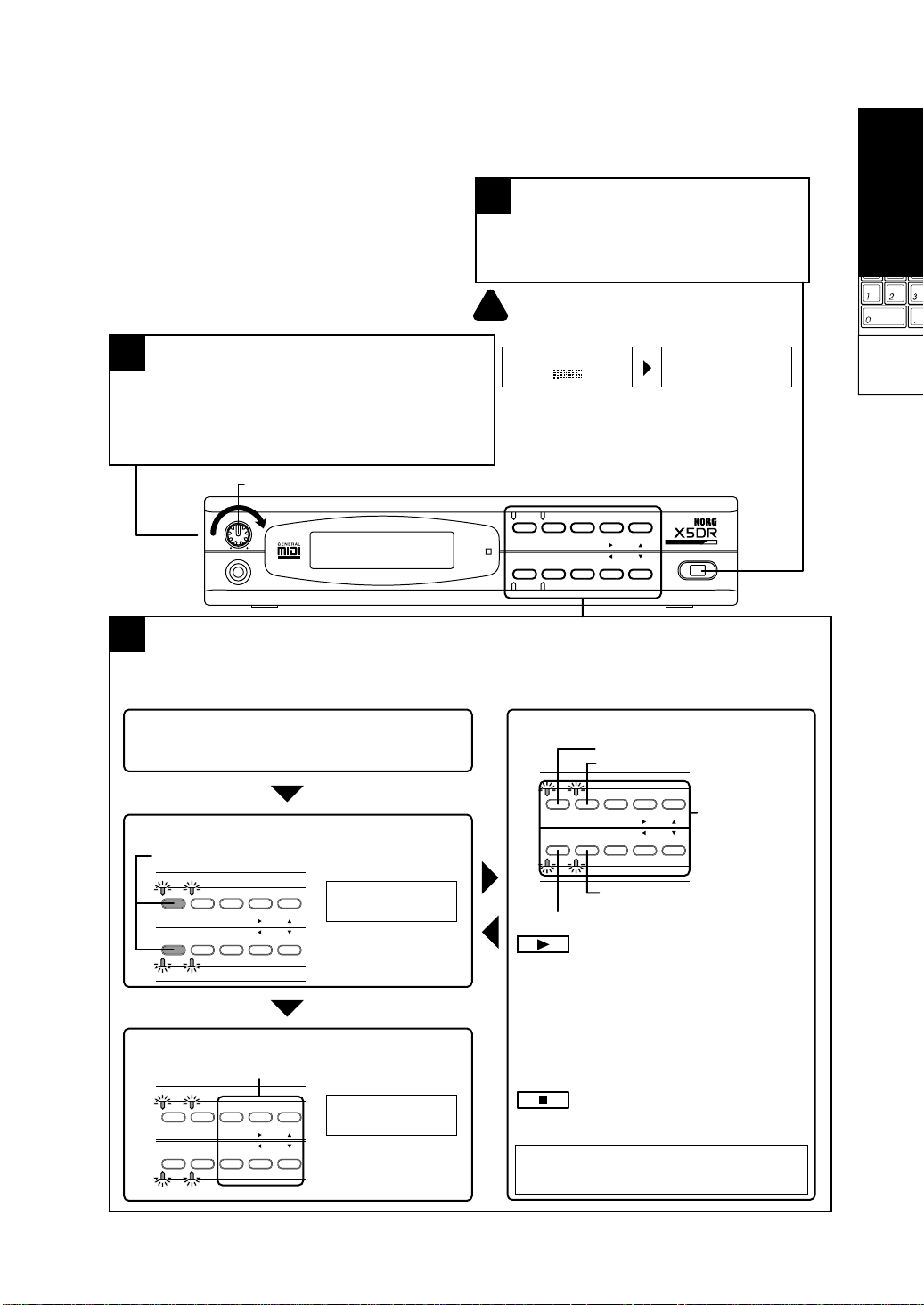
The X5DR has two internal songs that
demonstrate the X5DR's features. You can
play back these songs on the X5DR.
Adjusting the volume level
2
Use the VOLUME knob to set the optimum volume
level.
* The headphone volume level will be adjusted at
the same time.
VOLUME
VOLUME
100
PHONES
Demo performance
3
Demo Song 1: AROUND THE WORLD By Stephen Kay
Demo Song 2: WE’VE GOT DREAMS By KORG Inc.
Turning the power on/off
1
Press the power switch to turn the X5DR
power on. Pressing the power
switch again will turn the power off.
Make sure that the connected powered
!
speaker or stereo amplifier is turned off
before you power-on the X5DR.
X5DR 00:SolarFlare
A30 A99 A19 A39
When you turn the X5DR power on, the
screen will show the opening message
for a few seconds, then show the
Combination Play mode indication.
MIDI
COMBI PROG BANK
EDIT GLOBAL
MULTI
PAGE+
PAGE-
+10 +1
-10 -1
POWER
Start-up Guide
Using a
Keyboard
■ Combination Play mode
The X5DR automatically enters Combination Play mode
when you turn the power on.
■ To enter Demo mode:
Press the [COMBI] button and [EDIT] button
simultaneously.
Demo Play
COMBI PROG BANK
EDIT GLOBAL
MULTI
PAGE+
PAGE-
+10 +1
-10 -1
Press any key
* Four indicators will
flash in Demo mode.
■ To quit Demo mode:
Press one of the following buttons when playback is stopped.
00:SolarFlare
COMBI PROG BANK
EDIT GLOBAL
MULTI
PAGE+
PAGE-
+10 +1
-10 -1
A30 A99 A19 A39
* The X5DR will quit Demo
mode, and enter
Combination Play mode.
■ Operation in Demo mode
Demo Song 1: AROUND THE WORLD
Demo Song 2: WE’VE GOT DREAMS
COMBI PROG BANK
EDIT GLOBAL
MULTI
The X5DR will play back Demo song 1, then Demo song 2.
To listen to playback:
Press the [COMBI] button to playback Demo
song 1.
Press the [PROG] button to playback Demo
song 2.
Press the [EDIT] button to play demo songs 1
*
and 2 consecutively. Press the
[GLOBAL]/[MULTI] button to repeat the demo
songs in an endless loop.
To stop playback:
If you wish to stop the demo song, press any
button.
Listen to and enjoy the wonderful sound, the
versatile tone, and the rich expressiveness of the
Korg X5DR.
+10 +1
PAGE+
PAGE-
-10 -1
The X5DR will repeat playback of
Demo songs 1 and 2.
Pressing one of
these buttons will
stop playback.
3
Page 17
Start-up Guide
Playing Programs
The X5DR has two types of sounds: Programs and Combinations. First we will listen to some
Programs.
Program Play mode
1
Program Play mode enables you to play Programs.
Press the [PROG] button to enter Program Play mode.
A00:PipeDreams
The display shows the Program
Bank number, Program number,
Program name
Program number
Program Bank
VOLUME
100
PHONES
Changing Programs (2)
3
and Program name.
MIDI IN
MIDI OUT
MIDI keyboard
When you wish to change Programs from a connected
MIDI keyboard (or external MIDI device), you must
send Program Change messages (and also Bank
Select messages if you wish to change the Bank).
While Bank A is selected:
Sending Program Change messages 0–99 will select
Programs A00–99.
While Bank G is selected:
Sending Program Change messages 0–127 will select
Programs G01–128.
* To select Programs G129–136, send Bank Select
messages to change the Bank.
* Send the Bank Select messages to change the
Banks between A and G. (See page 22, 68.)
COMBI PROG BANK
MIDI
EDIT GLOBAL
MULTI
Changing Programs (1)
2
PAGE+
PAGE-
+10 +1
-10 -1
POWER
Use the [BANK], [+10]/[–10], and [+1]/[–1]
buttons to change Programs.
Pressing the [BANK] button repeatedly
toggles between Program Bank A and Bank G.
Pressing the [+10] or [–10]
COMBI PROG BANK
EDIT GLOBAL
MULTI
PAGE+
PAGE-
+10 +1
-10 -1
button repeatedly increments
or decrements a Program
number by 10.
Pressing the [+1] or [–1] button
repeatedly increments or
decrements a Program
number by 1.
The X5DR has 100 Programs in Bank A (A00–99),
and 136 Programs in Bank G (G01–136), for a total
of 236 Programs.
Bank A
A00–99
Bank G
G01–136
Listen to various Programs by changing Program
numbers.
* When the X5DR is shipped from the factory,
Bank A contains Preset a Programs. (See page
20, 156.)
4
Page 18

If No Sound is Produced:
If no sound is produced from the X5DR when you play the MIDI keyboard, or if you cannot
change Programs, check the following items:
No sound is produced:
Check to see if the Demo songs can be played. If not, check to see if the volume level of the X5DR
●
and the connected powered monitor or stereo amplifier is sufficient. Ensure that the audio cable is
connected correctly.
If the Demo songs can be played back, confirm that the unit is in Program Play mode. In Demo
●
mode, you cannot play Programs.
Check the MIDI cable connections and MIDI transmit channel on the MIDI keyboard. Set the
●
MIDI transmit channel of the MIDI keyboard to 1. If you cannot change the MIDI transmit
channel of the MIDI keyboard (if it is fixed), change the X5DR’s MIDI receive channel on page
2A MIDI GLOBAL in Global mode. (See page 151).
If you cannot change Programs:
If you cannot change Programs from the connected MIDI keyboard, check the transmit functions
●
on the MIDI keyboard. Some MIDI keyboards can be set so that they will not transmit any
Program Change messages. Some MIDI keyboards cannot transmit Bank Select messages, and
some interpret Bank Select messages differently from the X5DR. Check the transmit function of
your MIDI keyboard.
You can set the X5DR so that it will not receive Program Change or Bank Select messages. (The
●
default setting is to receive both messages.) If Programs are not changed when the MIDI ke yboard
transmits Program Change or Bank Select messages, check the MIDI FIL TER setting on page 2C
Global mode. (See page 152.)
Start-up Guide
Start-up Guide
Using a
Keyboard
Program Examples
The X5DR has 100 Programs (A00–99) in Bank A and 136 Programs (G01–136) in Bank G. Play
and listen to a variety of Programs. The following Programs exemplify the unique sound of the
X5DR. Take a listen to the following Programs.
A01:X Piano
This acoustic piano sound simulates a real piano—even the sound produced when the
hammer hits the string. Notice how dynamically the volume level and tonal color of the
sound varies, depending on key velocity (how strongly you strike the keys on the MIDI
keyboard). Playing the keyboard hard will make a bright sparkling sound, and playing it
softly will make a calmer sound. The simulation ranges from metallic lows to a short, hard
attack in the high range. The polyphony of 64 voices on the X5DR allows you to play
glissando and damper pedal effects.
A02:BigStrings
This Program recreates the dignified sound of a string section (including violin, viola, and
cello). The attack of the sound changes depending on the key velocity . Playing the k eyboard
softly slows the attack, and playing the keyboard hard will make the attack v ery f ast. With
a fast key velocity, it simulates an immediate attack and a bright sound with a subtle touch
of bow attack, allowing for a variety of performance expressions through key touch.
A08:Xanalog
This is a brass sound (such as trumpet or trombone) created on an analog synthesizer,
generally known as Synth Brass. You will also notice how dynamically the volume le vel and
tonal color of the sound varies depending on the key velocity and k e y range. This Program
is suitable for playing chords. Although the X5DR is an all-digital synthesizer, it is also
good at old classic analog sounds.
5
Page 19

Start-up Guide
A09:[KrazyKit]
A17:Velo Flute
A37:FreshWaves
A84:FeedbackGt
A90:Universe X
The Programs described above represent only a few of the Preset a Programs. Try se veral different
Programs and enjoy the great sounds of the X5DR.
This is a Program for a rhythm part (Drum Program), with a different sound assigned to
each key on the keyboard. The A09:[KrazyKit] Program contains not only drum sounds but
human voices and various ef fect sounds. When you play ke y C3 on the keyboard, the sound
does not stop—rather, the sound volume increases. Play key B2 to stop this sound.
This Program is a unique sound that simulates the sound of a flute. Play this Program with
different key velocities to change the tonal expression. You can also add vibrato ef fects by
sending modulation information.
This Program has a sparkling attack, unique to digital synthesizers. The X5DR offers
metallic and clear sounds, such as in this Program. Key touch affects the brightness of the
sound. It is very effective when used like an electric piano.
This is a powerful distorted guitar sound (amplifier distortion). As the name suggests, the
sound gradually changes to feedback. It sounds a lot like a guitar with a fully-cranked amp.
Try some guitar solos using modulation and pitch bend. The Delay effect can also be used
to great advantage.
This fantastic synth sound combines the soft sound of a female chorus with a sparkling
tremolo-like sound. Combine different types of sounds for interesting variations, and
expand your collection of creative sounds.
<<About Drum Kits>>
The following Programs use a Drum Kit: A09:[KrazyKit], A19:[ComboKit], and G129:GM Kit
through G136:Orch Kit.
A Drum Kit is a Program that consists of different drum sounds assigned to each key on the
keyboard. Therefore, one Drum Kit can play various drum and percussion sounds, instead of
playing scales. The X5DR has 8 Drum Kits in ROM and 2 Drum Kits in RAM. To play one of
these kits, select one in a Program. (First, set 0A OSC Mode in Program Edit mode to DRUMS,
then select the desirable kit for 1A OSC1 SOUND.) (See page 53, 79, 80). You can edit the sound
key assignments and settings of the Drum Kits in Global mode. (See page 53, 158).
<<About Preset Data>>
The X5DR has high quality preset sound data. There are two types of preset data: PRE-a and
PRE-b, and each contains 100 Programs, 100 Combinations, and 2 Drum Kits. Preset data PRE-a
is pre-loaded as the factory setting. To listen to or use PRE-b sounds, you need to load the preset
data PRE-b. Refer to “Loading Preset Data” on page 20, 156 for details.
6
Page 20
Playing Combinations
Combinations are another type of sound on the X5DR. We will listen to some Combinations now.
A Combination consists of several Programs. You can play different Programs by applying a
different key touch on the keyboard, or you can use Combinations to obtain a more complex
sound.
Start-up Guide
Combination Play mode
1
You can play Combinations in Combination Play mode.
Press the [COMBI] button to enter Combination Play mode.
The “
Combination number
Combination name
00:SolarFlare
A30 A99 A19 A39
Programs used for Timbres 1–4
VOLUME
100
PHONES
COMBI
MIDI IN
” mark appears for
*
Timbres 5–8.
00:SolarFlareX*
A78 OFF A70 A28
Programs used for
Timbres 5–8
MIDI
2
MIDI OUT
Use the [+10]/[–10] or the [+1]/[–1] buttons to
change Combinations.
■ What is Combination?
A Combination is a sound that consists of
up to eight Programs. Combinations allow
you to:
• Produce a thick and complex sound by
layering multiple Programs (Layer)
• Produce the sound of different Programs
depending on the range of the keyboard
(Split)
• Play different Programs by applying a
different key touch to the keyboard
(Velocity Switch).
Try different key ranges and key
velocities.
COMBI PROG BANK
EDIT GLOBAL
MULTI
PAGE+
PAGE-
+10 +1
-10 -1
POWER
Changing Combinations (1)
Start-up Guide
Using a
Keyboard
MIDI keyboard
Changing Combinations (2)
3
When you wish to change Combinations from a
connected MIDI keyboard, you need to send
Program Change messages.
Sending Program Change messages 0–99 will
select Combinations 00–99 respectively.
Pressing the [+10] or [–10]
COMBI PROG BANK
EDIT GLOBAL
MULTI
PAGE+
PAGE-
+10 +1
-10 -1
button repeatedly increments
or decrements a Combination
number by 10.
Pressing the [+1] or [–1] button
each time increments or
decrements a Combination
number by 1.
The X5DR has 100 Combinations (00–99).
Combinations
00–99
Listen to various Combinations by changing the
Combination numbers.
* When the X5DR is shipped from the factory, it
has Preset a Combinations. (See page 20,
156)
7
Page 21

Start-up Guide
Combination Examples
The X5DR has 100 Combinations (00–99). Play and listen to a variety of Combinations. The
following are some examples of the X5DR’s unique Combinations. Take a listen to the follo wing:
12:Wind→Orch
This orchestra sound combines woodwind, strings, and timpani sounds. With a low key
velocity , the w oodwind sound is produced, and with a high k e y velocity, a strings sound is
produced. This allows you to play two dif ferent sounds by switching the key velocity. In the
low range, the timpani sound and cymbal sound are produced only when you play the key
with a high key velocity. In this way, Combinations allow you to play different Programs
easily, depending only on the key range and key touch.
15:<The East>
This is an oriental Combination that consists of koto, shakuhachi, gamelan, and gong
sounds. Playing this Combination for even a short phrase is very effective and interesting
because it contains exotic ethnic instruments. This sound also changes depending on the key
range and key velocity.
26:Cathedral
This is a sublime pipe organ. This thick, heavy sound is created by layering multiple
Programs. Y ou can easily add thickness, width, and spaciousness to the sound by combining
different Programs.
39:<<<Hell>>>
As you might guess from the name, this is a weird sound that combines multiple drum
sounds and uses effect sounds, such as voices. Y ou can combine Drum Programs (drum and
effect sounds that are assigned to keys) with normal Programs, allo wing you to easily create
sounds with various characteristics. The next Combination 40:<<Heaven>> is a unique
contrast. Listen to and compare these two Combinations.
49:RapToolKit
This Combination consists of drum, bass, guitar, and effect sounds. You can play the drum
sound with the left hand, while playing the bass or guitar sound with the right hand. In the
mid range, the tonal color changes depending on the key velocity. With a low ke y v elocity,
a bass sound is produced. With a high key velocity, a guitar sound is added. The scratch
sound and orchestra hit sound are assigned to the higher range.
51:Bs/EP&Str
This combines bass, electric piano, and strings sounds. The bass Program is assigned to the
low range, and the electric piano and strings sounds are layered in the mid and high ranges.
You can play these different sounds with your left and right hands, which is very helpful in
live performance. Using Combination 81:Bass/Piano allows you to play an acoustic bass
and acoustic piano.
The Combinations described above are only part of a variety of Combinations the X5DR has to
offer in Preset a. Try playing different Combinations to enjoy the great sound of the X5DR.
8
Page 22
Using a Computer/Sequencer
Connections
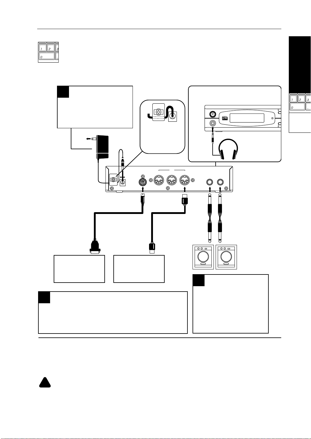
Connecting the power
1
Connect the AC adapter plug
to the DC IN connector on the
rear panel, and plug the AC
adapter into an AC outlet.
To the power outlet
AC Adapter
Secure the AC adapter
cable by hooking it as
shown in the illustration
to prevent the adapter
plug from being
accidentally removed.
Start-up Guide
To use the headphones, plug the
headphone cable into the PHONES jack
on the front panel.
VOLUME
100
PHONES
PHONES
Headphones
Start-up Guide
COM
MIDI
Using a
EDI
Computer/
Sequencer
DC IN
DC IN 12V
700mA
Computer interface cable
Computer
IBM PC compatible
Apple Macintosh
Connecting the computer/sequencer
3
TO HOST THRU OUT
or
MIDI cable
MIDI OUT
Computer/
Sequencer
There are two methods to connect your computer or
sequencer to the X5DR: “Connection via MIDI” and
“Computer interface cable.” Refer to page 10–13 for details.
MIDI
IN
OUTPUT
R L/MONO
L/MONO
R
Powered monitor
(such as the PM-15)
Connecting the monitor
2
Connect the OUTPUT jacks @
to the powered monitor or
stereo amplifier.
* Use the L/MONO jack for
monaural connection.
Powered monitor/stereo amplifier
In order to play back the X5DR’s high-fidelity sound, we recommend that you connect the X5DR to
powered monitors (speakers with built-in amplifiers, such as the optional PM-15). If you are going to
connect an audio stereo amplifier or other device (such as a stereo radio or a cassette tape recorder),
use the connector labeled “LINE IN” or “AUX IN” on those devices.
If you connect the X5DR to a domestic hi-fi system, be careful not to raise the volume level too
!
high or you may damage the speakers.
9
Page 23

Start-up Guide
Connecting a computer or sequencer
There are two methods by which you can connect the X5DR to a computer: using a MIDI cable
and MIDI interface (connection via MIDI), and using a computer interface cable to connect the
computer directly (connection via computer interface cable). Refer to the corresponding section
according to your computer and system. If you are using a stand-alone MIDI sequencer, read the
section about connection via MIDI.
Connecting the MIDI sequencer --- “Connection via MIDI” on page 11
●
●
Connecting the computer (Using MIDI interface) ---“Connection via MIDI” on page 11
●
Connecting an IBM PC compatible (using a computer interface cable) --- “Connecting an IBM PC
(Compatible) Computer” on page 12
Connecting an Apple Macintosh (using a computer interface cable) ---“Connecting an Apple
●
Macintosh Computer” on page 13
Connecting a computer
By connecting a computer to the X5DR using a computer interface cable, you can play the X5DR
sound from the computer. In addition, you can control other connected MIDI devices from the
computer using the X5DR as a MIDI interface.
You may connect the following types of computers to the X5DR using a dedicated cable (see
page 12–13).
IBM PC (compatible): Optional connection kit AG-001 (Cables, Software “KORG MIDI
Driver”)
Apple Macintosh series: Optional connection kit AG-002 (Cables, Software “KORG MIDI
Driver”)
You might not be able to use these connections depending on the model of computer or the type
of application software you use.
•
Do not connect the X5DR to a single external device via both MIDI OUT/IN and T O HOST at
the same time. Be sure to use only one of these connectors.
10
Page 24
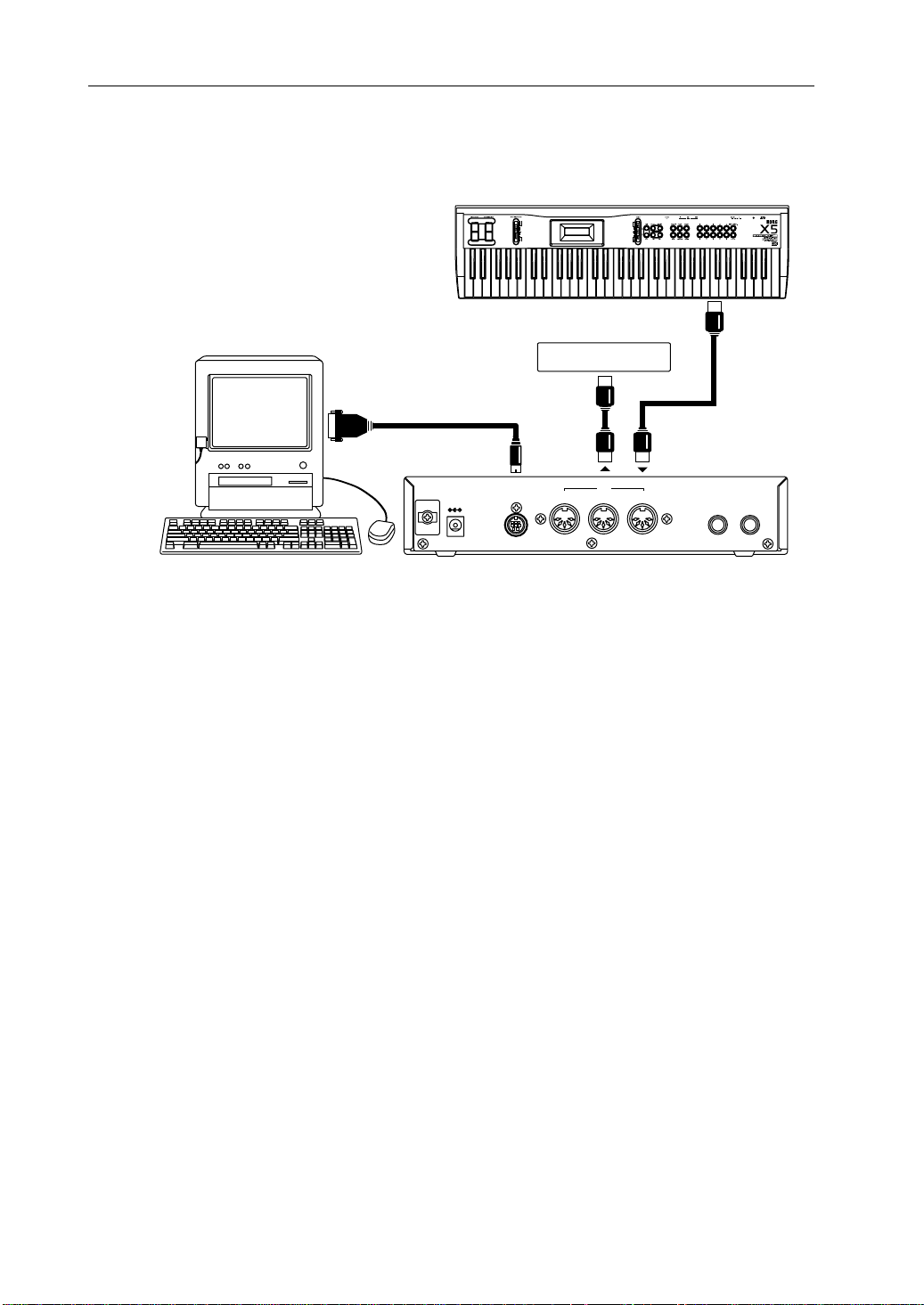
Connection via MIDI
T o connect a stand-alone MIDI sequencer or a computer with a MIDI interf ace to the X5DR, use
MIDI cables to connect MIDI OUT of the sequencer or computer (MIDI interface) to MIDI IN on
the X5DR.
Start-up Guide
Start-up Guide
IN
MIDI OUTMIDI Keyboard
MIDI IN
OUTPUT
R L/MONO
Computer/Sequencer
MIDI Interface
DC IN 12V
700mA
MIDI IN
MIDI OUT
TO HOST THRU OUT
MIDI
Connect the MIDI OUT jack of the MIDI keyboard to the MIDI IN jack on the sequencer or
computer (MIDI interface) using MIDI cables. If you input performance data from the computer
or sequencer, you do not have to connect the MIDI keyboard.
If you wish to connect an additional MIDI device, connect it to the MIDI OUT jack of the
sequencer or computer (MIDI interface), or to the MIDI THRU jack of the X5DR. Refer to “About
MIDI” on page 65 for information on connections using the MIDI THRU jack.
•
Refer to the manual that comes with the MIDI interface for information on the connection of
the computer and MIDI interface, and the MIDI port settings.
Using a
Computer/
Sequencer
11
Page 25
Start-up Guide
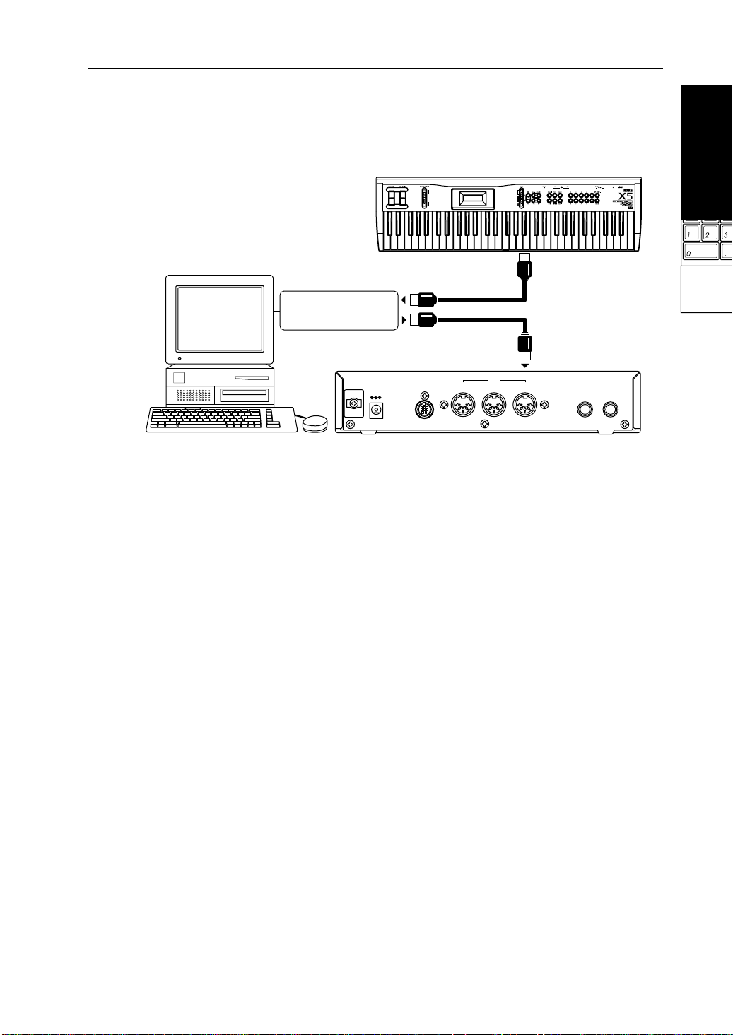
Connecting an IBM PC (Compatible) Computer
Connect the serial port (COM port) of the IBM PC (compatible) computer to the TO HOST
connector on the X5DR using a computer interface cable (optional AG-001).
MIDI OUTMIDI keyboard
IBM PC (compatible)
Computer interface cable
COM
(AG-001)
TO HOST
DC IN 12V
700mA
Other MIDI device
MIDI OUT
TO HOST THRU OUT
MIDI IN
MIDI
IN
OUTPUT
R L/MONO
To transmit data (such as Program data) from the TO HOST connector of the X5DR to the
computer, set 2B EXT OUT SEL of the Global mode to PCIF. (see page 14.)
•
You may not be able to use this connection, depending on the model of computer or the type
of sequencer software. Application software that is not compatible with Windows MME
(Multimedia Extensions) or W indows 3.1 (e xcept for those specifically supporting the X5DR)
cannot be used with this connection.
•
If the computer has a 25-pin serial port, use an optional AG-004 9-to-25-pin adapter.
Set 0D PC I/F CLK of the Global mode to “38.4kBPS” (see page 14).
If you use this connection with W indows MME or W indows 3.1, you need to install the K org MIDI
Driver. Refer to page 174 for installation information.
12
Page 26
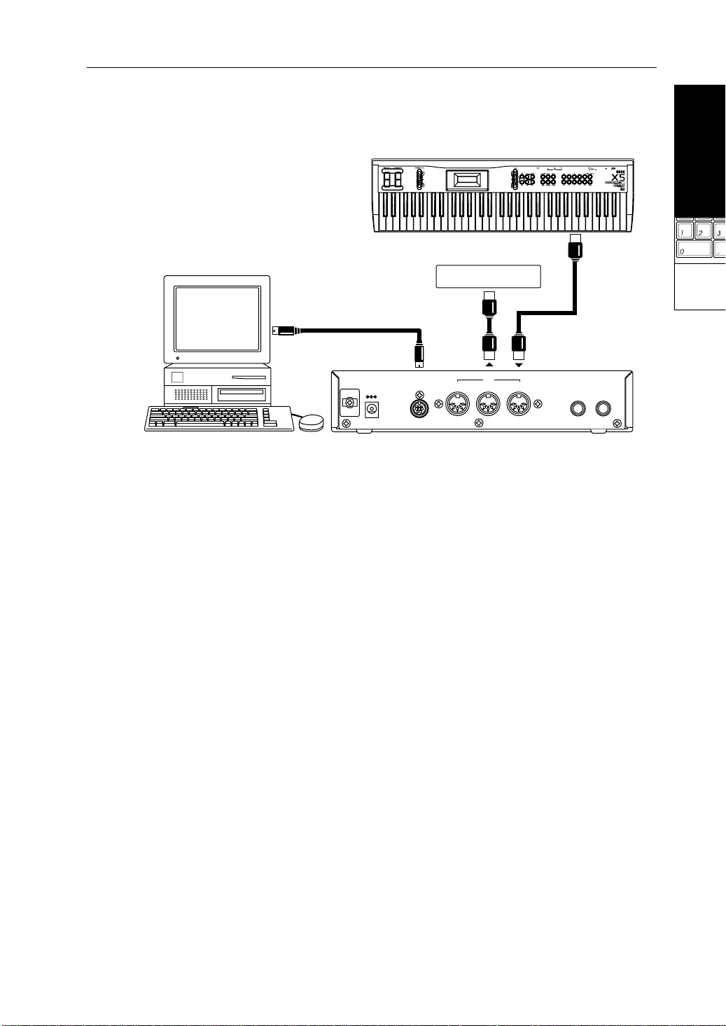
Connecting an Apple Macintosh Computer
Connect the modem port or printer port of the Apple Macintosh computer to the TO HOST
connector of the X5DR using a computer interface cable (optional AG-002).
Start-up Guide
Start-up Guide
Apple Macintosh
Modem port or printer port
Computer interface cable
(AG-002)
TO HOST
DC IN 12V
700mA
MIDI Keyboard
Other MIDI device
MIDI OUT
TO HOST THRU OUT
MIDI IN
MIDI
IN
MIDI OUT
OUTPUT
R L/MONO
To transmit data (such as Program data) from the TO HOST connector of the X5DR to the
computer, set 2B EXT OUT SEL of Global mode to PCIF. (See page 14.)
•
This connection might not be used, depending on the model of the computer or the type of
sequencer software.
•
If your sequencer software has a clock setting, set the clock to 1MHz.
Set 0D PC I/F CLK of the Global mode to “31.25kBPS.” (See page 14.)
Installing the Korg MIDI Dri v er allo ws the X5DR to output data from its internal tone generator
separately from MIDI OUT data. This makes it possible to use the X5DR as a MIDI interface for
other connected devices. Refer to page 177 for installation information.
Using a
Computer/
Sequencer
13
Page 27
Start-up Guide
Settings Required When a Computer is Connected
If you have connected the X5DR to the computer using a computer interface cable, set the
Computer Select (data transfer rate from/to the computer) and External Out Select (data
transmission destination from the X5DR).
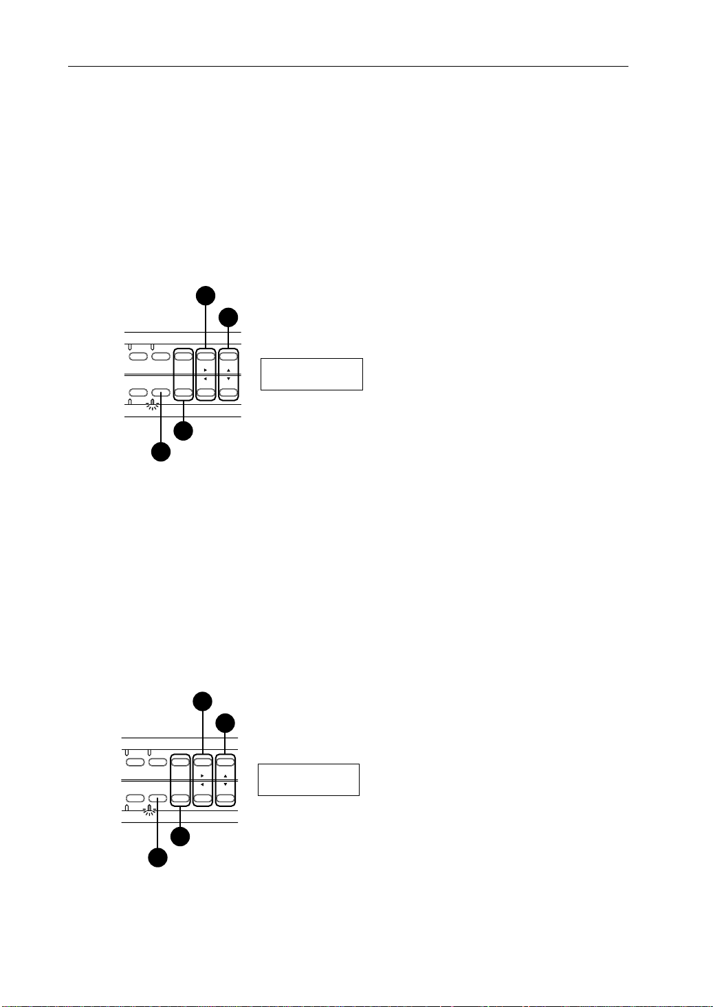
Setting Computer Select (0D PCI/F CLK in Global Mode)
1 Press the [GLOBAL] button to enter Global mode. 2 Select 0A MASTER TUNE (by pressing the [PAGE–] button). 3 Press the [ 4 Use the [
®
] button four times to display 0D PC I/F CLK.
▲
] and [▼] buttons to set the value.
Press the [¤] button four times.
3
Select 31.25kBPS or 38.4kBPS.
4
COMBI PROG BANK
EDIT GLOBAL
MULTI
1
+10 +1
PAGE+
PAGE-
-10 -1
Press the [PAGE+] or [PAGE–] button.
2
Press the [GLOBAL] button to enter Global mode.
00D PC I/F CLK
38.4 kBPS
If you connect the X5DR to an IBM PC compatible computer, set this parameter to 38.4kBPS. If
you connect the X5DR to an Apple Macintosh computer, select 31.25kBPS.
Setting External Out Select (2B EXT OUT SEL in Global Mode)
1 Press the [GLOBAL] button to enter Global mode.
The [GLOBAL] button allows you to switch between Global mode and Multi mode. When the
X5DR is in Multi mode (the indicator lights up), press the [GLOBAL] button again to enter Global
mode (the indicator flashes).
2 Press the [PAGE+] or [PAGE–] button to select 2A MIDI GLOBAL.
3 Press the [
4 Use the [
®
] button twice to display 2B EXT OUT SEL.
▲
] and [▼] buttons to assign the function.
Press the [¤] button twice.
3
Select MIDI or PCIF.
4
14
COMBI PROG BANK
EDIT GLOBAL
MULTI
1
+10 +1
PAGE+
PAGE-
-10 -1
Press the [PAGE+] or [PAGE–] button.
2
Press the [GLOBAL] button to enter Global mode.
02B EXT OUT SEL
PCIF
Select “MIDI” to transmit the X5DR data from MIDI OUT, and select “PCIF” to transmit it from
TO HOST.
Page 28
Listening to a Demo performance
Start-up Guide
The X5DR has two internal songs that
demonstrate the X5DR's features. You can
play back these songs on the X5DR.
Adjusting the volume level
2
Use the VOLUME knob to set the optimum volume
level.
* The headphone volume level will be adjusted at
the same time.
VOLUME
VOLUME
100
PHONES
Demo performance
3
Demo Song 1: AROUND THE WORLD By Stephen Kay
Demo Song 2: WE’VE GOT DREAMS By KORG Inc.
Turning the power on/off
1
Press the power switch to turn the X5DR
power on. Pressing the power
switch again will turn the power off.
Make sure that the connected powered
!
speaker or stereo amplifier is turned off
before you power-on the X5DR.
X5DR 00:SolarFlare
A30 A99 A19 A39
When you turn the X5DR power on, the
screen will show the opening message
for a few seconds, then show the
Combination Play mode indication.
MIDI
COMBI PROG BANK
EDIT GLOBAL
MULTI
PAGE+
PAGE-
+10 +1
-10 -1
POWER
Start-up Guide
Using a
Computer/
Sequencer
■ Combination Play mode
The X5DR automatically enters Combination Play mode
when you turn the power on.
■ To enter Demo mode:
Press the [COMBI] button and [EDIT] button
simultaneously.
Demo Play
COMBI PROG BANK
EDIT GLOBAL
MULTI
PAGE+
PAGE-
+10 +1
-10 -1
Press any key
* Four indicators will
flash in Demo mode.
■ To quit Demo mode:
Press one of the following buttons when playback is stopped.
00:SolarFlare
COMBI PROG BANK
EDIT GLOBAL
MULTI
PAGE+
PAGE-
+10 +1
-10 -1
A30 A99 A19 A39
* The X5DR will quit Demo
mode, and enter
Combination Play mode.
■ Operation in Demo mode
Demo Song 1: AROUND THE WORLD
Demo Song 2: WE’VE GOT DREAMS
COMBI PROG BANK
EDIT GLOBAL
MULTI
The X5DR will play back Demo song 1, then Demo song 2.
To listen to playback:
Press the [COMBI] button to playback Demo
song 1.
Press the [PROG] button to playback Demo
song 2.
Press the [EDIT] button to play demo songs 1
*
and 2 consecutively. Press the
[GLOBAL]/[MULTI] button to repeat the demo
songs in an endless loop.
To stop playback:
If you wish to stop the demo song, press any
button.
Listen to and enjoy the wonderful sound, the
versatile tone, and the rich expressiveness of the
Korg X5DR.
+10 +1
PAGE+
PAGE-
-10 -1
The X5DR will repeat playback of
Demo songs 1 and 2.
Pressing one of
these buttons will
stop playback.
15
Page 29
Start-up Guide
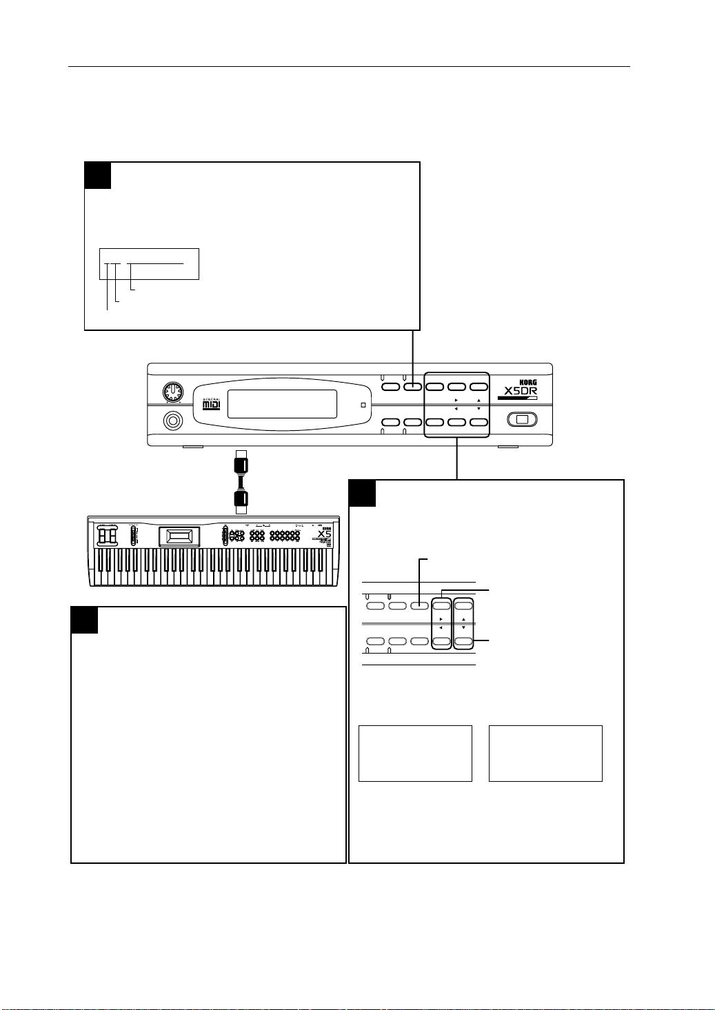
Playing the X5DR in Multi Mode (Playing Back GM Scores)
Multi mode allows you to use the X5DR as a 16-channel multi-timbre (GM) tone generator,
controlled from the connected computer, to play ensemble music consisting of multiple
instrument parts. This section explains playing the X5DR in Multi mode.
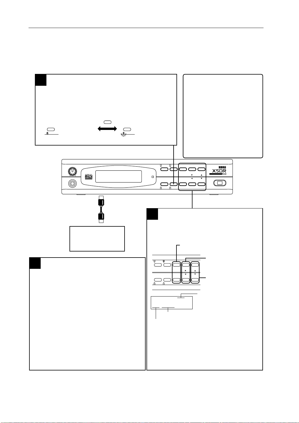
Multi mode
1
Press the [MULTI] button to enter Multi mode.
* The [MULTI] button allows you to switch between Global mode and Multi
mode. When the X5DR is in Global mode (the indicator flashes), press the
[MULTI] button again to enter Multi mode (the indicator lights up).
GLOBAL
● Multi mode:
MULTI
The indicator lights up.
VOLUME
100
PHONES
GLOBAL
MULTI
MIDI IN
MIDI OUT
GLOBAL
MULTI
● Global mode:
Indicator flashes.
Computer/
Sequencer
Changing Track Programs (2)
3
When you wish to change Programs from a
connected computer or sequencer, you need to
send Program Change messages. (See the page
17, 66, 68.)
While Bank A is selected:
Sending Program Change messages 0–99 will select
Programs A00–99.
While Bank G is selected:
Sending Program Change messages 0–127 will select
Programs G01–128.
* To select Programs G129–136, send Bank Select
messages to change the Bank.
* Send the Bank Select messages to change the
Banks between A and G.
■ What is Multi mode?
Multi mode allows you to use the X5DR as
a 16-channel multi-timbre (GM) tone
generator. You can play different
Programs assigned to 16 tracks. When
you turn on the power to the X5DR, Multi
mode uses a default GM setting, which
allows you to play back a GM score (GM
performance data) right away. If you wish
to restore the GM default setting, send the
GM System On message or set 23A SET
TO GM accordingly.
* If the GM score is not played back
correctly, refer to “Notes on playing back
GM scores” on Page 18.
COMBI PROG BANK
MIDI
EDIT GLOBAL
MULTI
Changing Track Programs (1)
2
PAGE+
PAGE-
+10 +1
-10 -1
POWER
Use the [PAGE+], [PAGE–], [¤], [ˆ], [▲], [▼]
buttons to change a Program for each track.
Use [PAGE+] and [PAGE–] buttons to select
a track.
Use the [¤] and [ˆ] buttons to
COMBI PROG BANK
EDIT GLOBAL
MULTI
00A MULTI T01 ø
G01:Piano
Track Program name
Track Program (A00–99, G01–136)
PAGE+
PAGE-
+10 +1
-10 -1
select a parameter.
Use the [▲] and [▼] buttons to
change the Track Program
setting.
Track number (T01–T16)
The X5DR has 100 Programs in Bank A (A00–99),
and 136 Programs in Bank G (G01–136), for a total
236 Programs.
* When the X5DR is shipped from the factory,
Bank A has Preset a Programs. (See page 20,
156.)
16
Page 30
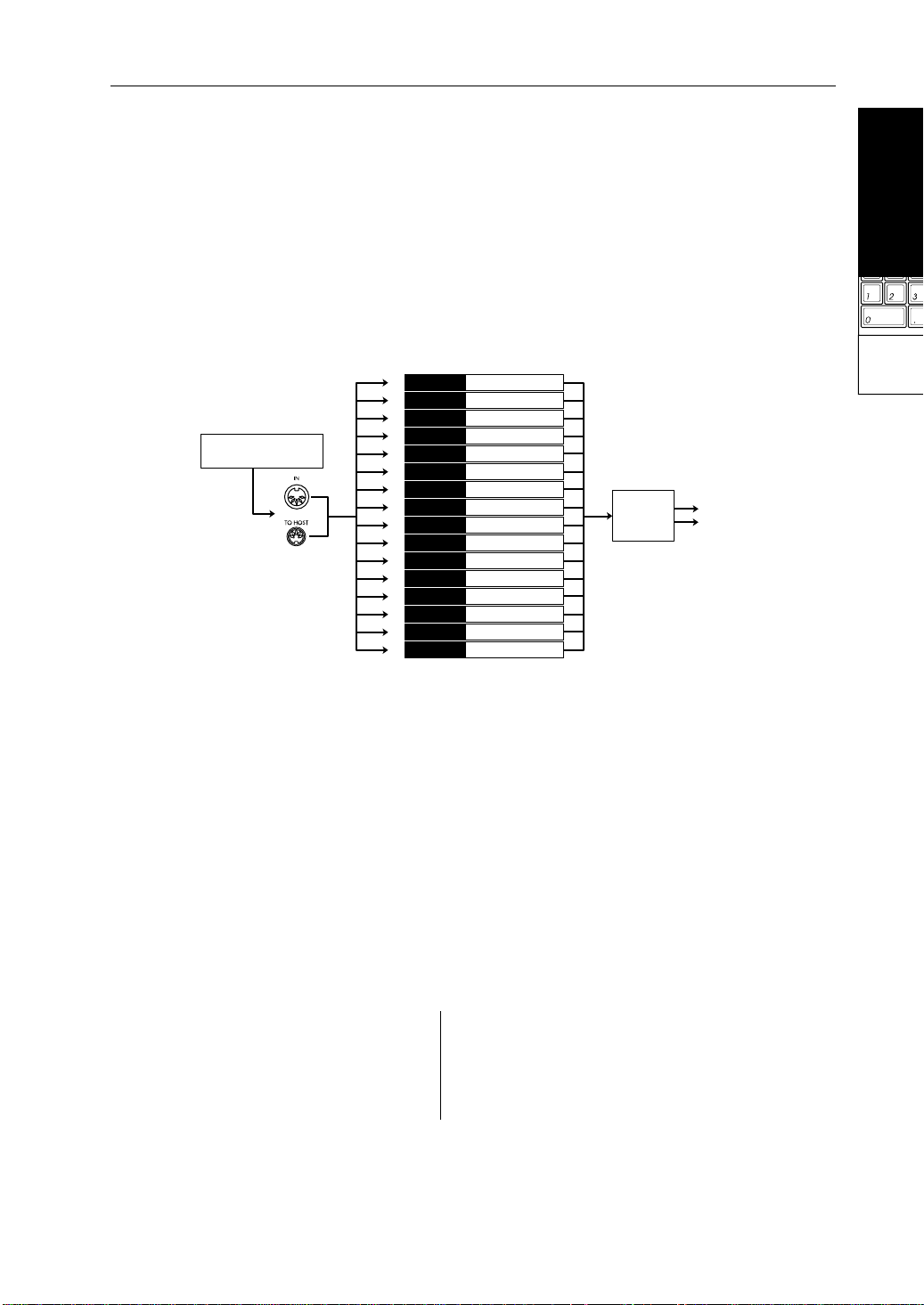
Structure of Multi Mode
Multi mode allows you to use the X5DR as a GM tone generator which conforms to General MIDI
System Level 1.
When GM ON messages are received or when the power is turned on, the GM settings are
automatically selected. Y ou can restore the GM settings in 23A SET TO GM (see page 114). When
the GM settings are selected, MIDI Channels for Tracks 1–16 will become 1–16, respectively.
Track 10 (MIDI Channel 10) is used for a rhythm part:G129:GM Kit. Other tracks are assigned
G01: Piano.
Y ou can play dif ferent T rack Programs on each track by transmitting performance information via
the MIDI channel that corresponds to each track from a computer or sequencer.
Start-up Guide
Start-up Guide
Default setting for GM MIDI Channel
MIDI Channel
External sequencer
or computer
Track 1010
Program G01Track 11
Program G01Track 22
Program G01Track 33
Program G01Track 44
Program G01Track 55
Program G01Track 66
Program G01Track 77
Program G01Track 88
Program G01Track 99
Drum Program G129
Program G01Track 1111
Program G01Track 1212
Program G01Track 1313
Program G01Track 1414
Program G01Track 1515
Program G01Track 1616
Effect
units
L/MONO
R
Selecting a Track Program From a Computer or Sequencer
Send the Program Change message on the MIDI channel that corresponds to each track from a
connected computer or sequencer to select Track Programs.
To change Program Banks, send Control Change Bank Select (Controller 0/32). The X5DR will
select a new Program when it receives a Program Change message following a Bank Select
message.
Program Bank MIDI Bank Select
Bank A (A00–A99) CTRL#0=0 CTRL#32=0
Bank G (G01–128) CTRL#0=56 CTRL#32=any number
Drum Program (G129–136) CTRL#0=62 CTRL#32=any number
Using a
Computer/
Sequencer
The following Programs G01–128 are different than Programs G129–136 in terms of their
response to Bank Select messages.
Program numbers used to select a Drum Program (G129–136) in the Drum Program Bank:
Drum Program Program Number Drum Program Program Number
G129 0 G133 40
G130 16 G134 64
G131 25 G135 24
G132 32 G136 48
•
Transmit functions and operations for Bank Select messages and Program numbers are
different depending on the type of connected sequencer or sequence software. Refer to your
sequencer or sequence software manual for detailed operational information.
17
Page 31

Start-up Guide
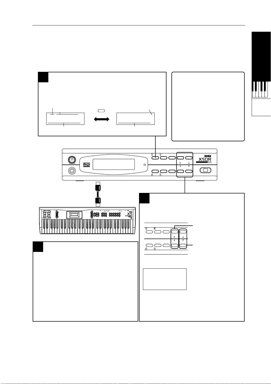
Performance settings
Parameters on the X5DR, or MIDI data sent from a computer or sequencer, allow you to make
performance settings such as volume level and pan of each track.
On the X5DR, use the [PAGE+] and [PAGE–] buttons to select a track, then use the [®] and [
buttons to select a parameter.
You may set the following parameters by sending the Controllers and RPN from the connected
computer or sequencer. You may also set all the parameters using the Exclusive messages.
For details, refer to “Received MIDI data” on page 32, and “MIDI Data” on page 66.
Parameters MIDI Data
Lev:
Volume.........................Controller #7
Pan:
Pan...............................Controller #10
Sen:
Send C/D.....................Controller #91/#93
Tra:
Transpose.....................RPN 02
Det:
Detune..........................RPN01
Bnd:
Bend range .................RPN 00
Pf:
Program Change filter
Df:
Damper filter
Af:
After Touch filter
Cf:
Control Change filter
KWTop/KWBtm:
VWTop/VWBtm:
MIDI Ch:
MIDI channel
Key Window
Velocity Window
]
√
Notes on Playing Back GM Scores
Before playing back performance data (GM scores) for a GM tone generator, make sure that the
following settings have been made in Global mode for correct playback.
0B Key T ranspose +00
0C Velocity Curve 3
After T ouch Curve 3
1A Scale Type Equal T emp
2A Note Receive ALL
2C–2D MIDI Filter PRG=NUM, EX=DIS, Others=ENA
•
See page 146 for the function of each parameter.
Set all the parameters in Multi mode to their default setting. To do so, use 23A SET TO GM (see
page 114), or transmit a GM System On message from a computer or sequencer.
Some GM scores may include non-GM MIDI data. In particular, Program Change messages may
be interpreted as Bank Select messages (for Bank A) when you are playing back a GM score that
uses Bank Select messages. (Bank G contains 128 GM sounds and Drum Programs.) If you wish
to play back performance data that has been created, assuming that it will be played back on the
X5DR, set the PRG parameter of the MIDI filter in Global mode to “ENA.” To play back other
performance data, set this to “NUM” to ignore the Bank Select messages.
18
Page 32

If You Cannot Play the X5DR
If no sound is produced from the X5DR or if the sound or performance is not proper, check the
following items:
No sound is produced:
Check to see if Demo songs can be played. If not, check to see if the volume level of the X5DR
●
and the connected powered monitor or stereo amplifier is sufficiently raised. Ensure that the audio
cable is connected correctly.
If Demo songs can be played back, confirm that the unit is in Multi mode.
●
●
Check the connection of the MIDI cables or computer interface cables, and the settings on the
computer or sequencer. When the X5DR receives MIDI data, the MIDI indicator lights up. If the
MIDI indicator does not light up, the settings on the computer or sequencer may not be correct.
If you are using a computer interface cable, check to see if 0D PC I/F CLK in Global mode is set
●
correctly. For an IBM PC (compatible), set this parameter to 38.4kBPS. For an Apple Macintosh
computer, set it to 31.25kBPS. (See page 14.)
You need to set up the MIDI port for MIDI data transmission/reception when you are using
●
sequence software on the computer. Check to see if the MIDI port for the connected MIDI
interface or KORG MIDI Driver port has been selected. The KORG MIDI Driver allows you to
use different MIDI ports for the tone generator inside the X5DR and MIDI data transmitted from
the MIDI OUT connector. To play the X5DR, specify the X5DR’s tone generator (K ORG PC I/F
Synth Port).
Some W indows sequence software may transmit MIDI data via MIDI mapper . If you are using this
●
type of software, use the MIDI mapper on the control panel to change the port name of all the
MIDI channel maps to KORG PC I/F Synth Port.
Start-up Guide
Start-up Guide
Using a
Computer/
Sequencer
If Programs or Performance Sound Wrong
●
If the Program sounds wrong during the playback of the GM score, the GM score may be using
the Bank Select message. In this case, set the computer or sequencer so that it will not transmit the
Bank Select messages, or set 2C MIDI FIL TER in Global mode so that the X5DR will not recei ve
the Bank Select messages. (See page 152.) Then, transmit the GM System On message from the
computer or sequencer, or use 23A SET T O GM to restore the default setting, and play the X5DR
again.
If the volume level or pan setting is incorrect, or the parameter settings are not reflected by the
●
performance of the X5DR, the information has probably been cut by the transmission filter of the
sequencer/sequence software, or by the KORG MIDI Driver filter. You can set the X5DR using
the MIDI FIL TER (page 152) in Global mode, and Multi mode so that the X5DR will not receiv e
MIDI messages (page 111). Check these settings again.
In Multi mode, you can use the X5DR as a 16-part multi-timbral GM tone generator. You can set
●
a Track’s Program, volume, and pan settings on the computer or sequencer as well as on the
X5DR. (This setting data allows the X5DR to play the performance data in the same conditions.)
If these data have not been input, the X5DR may play the performance data using the previous
playback settings. Refer to your sequencer/sequence software manual for information on how to
create performance data and how to play each track.
19
Page 33

Start-up Guide
Loading Preset Data
The X5DR has 200 carefully-selected Programs and Combinations (100 types of each) and four
Drum Kits (2 types
•
Preset a was loaded when the X5DR was shipped from the factory.
1 Press the [Global] button to enter Global mode.
2), which are all included as Preset data (Preset a/b).
×
COMBI PROG BANK
EDIT GLOBAL
MULTI
PAGE+
PAGE-
+10 +1
-10 -1
Press the [Global] button.
The [GLOBAL] button allows you to switch between Global mode and Multi mode. When the
X5DR is in Multi mode (the indicator lights up), press the [GLOBAL] button again to enter Global
mode (the indicator flashes).
2 Press the [PAGE+] or [PAGE–] button to select 5A PRESET DATA.
Press the [PAGE+] or [PAGE–] button.
COMBI PROG BANK
EDIT GLOBAL
MULTI
PAGE+
PAGE-
+10 +1
-10 -1
05A PRESET DATA
ALL PRE-a OK?
3 Set the left end indication (loading source) to “ALL,” and move the cursor to the next
parameter (selecting Preset a and b), and select PRE-a or PRE-b.
Move the cursor using the [¤] and [ˆ] buttons.
COMBI PROG BANK
EDIT GLOBAL
MULTI
PAGE+
PAGE-
+10 +1
-10 -1
05A PRESET DATA
ALL PRE-b OK?
Set the parameter using the [▲] and [▼] buttons.
Move the cursor using the [®] and [√] buttons, and set the parameter using the [▲] and [▼]
buttons.
4 Move the cursor to “OK?” and press the [▲] button. Press the [▲] button again in response
to the message “Are You Sure OK?”.
Press the [▲] button again in response to the message
“Are You Sure OK?”.
COMBI PROG BANK
EDIT GLOBAL
MULTI
PAGE+
PAGE-
+10 +1
-10 -1
05A PRESET DATA
ALL PRE-b OK?
05A PRESET DATA
Are You Sure OK?
In the example above, the loading source is set to “ALL.” However, you can select different
sources. Refer to page 156.
20
Page 34

1. X5DR Modes
Basic Guide
X5DR
Modes
1
There are six operating modes on the X5DR for use with different performances, settings, and
functions: Program Play, Program Edit, Combination Play, Combination Edit, Multi, and Global.
Program Play mode
Programs are basic sounds that you can play in Program Play mode. The X5DR contains 236
Programs organized in banks as follows: 100 (A00–99) in RAM (Random Access Memory) where
you can store created or edited sounds, and 136 (G01–136) in the built-in preset area.
A00–A99 G01–G136
You can store a total of
100 Programs.
Bank A Bank G
G01–G128 :
G129–G136:
Basic Guide
Basic Guide
128 GM compatible
Programs
8 Drum kit Programs
Playing Programs
To play Programs in Program Play mode, set the transmission device (such as a MIDI keyboard
or computer) so that its MIDI transmission channel will match the X5DR Global MIDI Channel.
Set the X5DR Global MIDI Channel in 2A MIDI GLOBAL in Global mode (see page 151).
Basic operation in Program Play mode
Press the [PROG] button to enter Program Play mode to play Programs.
Press the [PROG] button.
COMBI PROG BANK
EDIT GLOBAL
MULTI
You can switch Programs in Program Play mode by operating the front panel of the X5DR, or by
sending MIDI data from an external device.
Changing Programs on the unit
●
[BANK] button: Switches between Bank A and G.
●
[+10]/[–10] button: Increase/decrease the Program number in steps of 10.
PAGE+
PAGE-
+10 +1
-10 -1
A00:PipeDreams
Basic Guide
1
X5DR
Modes
21
Page 35

Basic Guide
●
[+1]/[–1] button: Increase/decrease the Program number in steps of 1.
Pressing the [BANK] button each time will toggle between Bank A and G.
Pressing the [+10]/[–10] button increases/decreases the Program
COMBI PROG BANK
EDIT GLOBAL
[BANK] button
[+10]/[–10] button
MULTI
PAGE+
PAGE-
+10 +1
-10 -1
A00:PipeDreams
A00:PipeDreams A10:Transforms
number in steps of 10.
Pressing the [+1]/[–1] button increases/decreases the Program number
in steps of 1.
BANK
PAGE+
BANK
PAGE+
+10
-10
G01:Piano
+1
-1
[+1]/[–1] button
A00:PipeDreams A01:X Piano
Changing Programs via MIDI
Transmit Program Change messages to change Programs from a MIDI keyboard or e xternal MIDI
device. The X5DR will change Programs within the bank when it receives a Program Change
message.
•
In Bank A, the X5DR interprets MIDI Program Numbers 100–127 as Programs A00–27.
•
In Bank G, the X5DR interprets MIDI Program Numbers 0–127 as Programs G01–128.
To change Program Banks, send a Control Change Bank Select (Controller 0/32) message. The
X5DR will select a new Program when it receives a Program Change message following a Bank
Select message.
Program Bank MIDI Bank Select
Bank A (A00–A99) CTRL#0=0 CTRL#32=0
Bank G (G01–128) CTRL#0=56 CTRL#32=any number
Drum Program (G129–136) CTRL#0=62 CTRL#32=any number
The following Programs G01–128 are different than Programs G129–136 in terms of their
response to Bank Select messages.
Program numbers are used to select a Drum Program (G129–136) in the Drum Program Bank:
Drum Program Program Number Drum Program Program Number
G129 0 G133 40
G130 16 G134 64
G131 25 G135 24
G132 32 G136 48
22
•
Transmit functions and operations for Bank Select messages and Program numbers are
different depending on the type of the connected MIDI keyboard. Refer to your MIDI ke yboard
manual for detailed operational information.
Page 36

Program Edit Mode
Program Edit mode allows you to modify
the sound of Programs. The figure shows
the structure of a Program. You can create
your own sound and modify its tonal color
by modifying these parameters in
Program Edit mode.
Basic operation in Program Edit mode
Press the [EDIT] button while in Program Play mode to enter Program Edit mode.
Pitch1 MG VDF1 EG VDA1 EG
Oscillator1 VDF1 VDA1
Pitch EG VDF MG
Oscillator2 VDF2 VDA2
Pitch2 MG VDF2 EG VDA2 EG
Send C&D
Pitch Bend Wheel
& Modulation Wheel
Double Oscillator mode only
Pan A&B
Pan A&B
Send C&D
Basic Guide
Audio signal
Control signal
Effects
L/MONO
R
COMBI PROG BANK
EDIT GLOBAL
MULTI
PAGE+
PAGE-
+10 +1
-10 -1
00A OSC Mode ø
DOUBLE
Press the [EDIT] button in Program Play mode.
In Program Edit mode, use the [PAGE+] and [PAGE–] buttons to switch the pages, and use the
[®] and [
[
▼
COMBI PROG BANK
EDIT GLOBAL
[PAGE+] and [PAGE–] buttons
[ˆ] and [¤] buttons
[▲] and [▼] buttons
] buttons to move the cursor (flashing line) and select a parameter , and use the [▲] and
√
] buttons to set the value.
Use the [PAGE+] and [PAGE–] buttons to select a page.
Use the [ˆ] and [¤] buttons to move the cursor (flashing line) and
select a parameter.
Use the [▲] and [▼] buttons to set the value.
BANK
00AXOSCXModeXXXø
PAGE+
XXXXDOUBLE
BANK
PAGE+
00AXOSCXModeXXXø
XXXXDOUBLE
00AXOSCXModeXXXø
XXXXDOUBLE
+10
-10
+1
-1
01AXOSC1XSOUNDXø
X385:FluteFXXLP
00BXOSC1
ASN:POLYXHLD:OFF
00AXOSCXModeXXXø
XXXXDRUMS
ø
MULTI
PAGE+
PAGE-
+10 +1
-10 -1
Basic Guide
1
X5DR
Modes
You can write a Program that you created and edited in Program Edit mode to Program Bank A
(A00–99).
Refer to “3. Editing” (page 36) for information on how to edit Programs, and refer to “1. Program
Parameters” (page 78) for information on the parameter functions.
23
Page 37

Basic Guide
Combination Play Mode
Combinations (a combination of Programs) can use up to eight Timbres. Each T imbre is assigned
a Program. You can play Combinations in Combination Play mode. The X5DR contains 100
Combinations (00–99).
00–99
You can store a total of
100 Combinations.
Playing Combinations
The eight Timbres in Combinations can be assigned to different MIDI Channels. (Initially, all
Timbres are assigned to MIDI Channel 1.) Set the MIDI receiv e channel of each Timbre so that it
matches the MIDI channel of the transmission device such as a computer or MIDI keyboard.
Combination Play mode allows you to combine up to eight Programs, and is useful in live
performance. Y ou can also use the X5DR as a multi-timbral tone generator by assigning a dif ferent
MIDI channel to each Timbre.
•
Each Timbre in a Combination has MIDI filters for MIDI message such as Program Change,
Damper (Hold 1), After T ouch, and Control Change. Therefore, MIDI data for which the MIDI
filter is set to “D (Disable)” will be ignored. (See page 104.)
Timbre 1
Timbre 2
Timbre 3
Timbre 4
Timbre 5
Timbre 6
Timbre 7
Timbre 8
Key Window
Keyboard range played by
each Timbre
Effects
This example shows that each Program
assigned to a corresponding Timbre is
set in such a way that the Programs will
produce sound in different ranges of the
keyboard.
Basic operation in Combination Play mode.
Press the [COMBI] button to enter Combination Play mode to play Combinations.
Press the [COMBI] button.
24
COMBI PROG BANK
EDIT GLOBAL
MULTI
You can switch Combinations in Combination Play mode by operating the front panel of the
X5DR, or by sending MIDI data from an external device.
PAGE+
PAGE-
+10 +1
-10 -1
00:SolarFlare
A30 A99 A16 A39
Page 38

Changing Combinations on the unit
[+10]/[–10] button: Increase/decrease the Combination number in steps of 10.
●
●
[+1]/[–1] button: Increase/decrease the Combination number in steps of 1.
Pressing the [+10]/[–10] button increases/decreases the
COMBI PROG BANK
EDIT GLOBAL
MULTI
PAGE+
PAGE-
+10 +1
-10 -1
Combination number in steps of 10.
Pressing the [+1]/[–1] button increases/decreases the
Combination number in steps of 1.
Basic Guide
+10
-10
+1
-1
X10:<The West>
A13XA01XG48XA19
X01:StereoKeys
A41XA01XA01XA01
[+10]/[–10] button
[+1]/[–1] button
X00:SolarFlare
A30XA99XA19XA39
X00:SolarFlare
A30XA99XA19XA39
Changing Combinations via MIDI
Transmit a Program Change message on the Global MIDI Channel to change Combinations from
an external MIDI device.
When you send Program Change messages to the X5DR for channels other than the Global MIDI
Channel, the individual Programs within the Combination will change.
•
Refer to page 22 for information on selecting a Program for each Timbre via MIDI.
Combination T ypes
Y ou can combine v arious Programs by editing the T imbre settings in Combinations. F or example,
you can play a different Program with each hand, or you can play different Programs by applying
a different key touch (ke y velocity) to the keyboard. These techniques are v ery useful and powerful
in live performance. Settings that determine the combination of Programs are made in
Combination Edit mode. (See “Editing Combinations” on page 51.) Let’s take a look at the
various types of Combinations that are available.
Layer
The X5DR produces the sound of multiple Programs simultaneously. When Timbres are
layered together, they produce a thick and complex Combination, such as a piano sound
overlapped with a strings sound.
Basic Guide
1
X5DR
Modes
Split
Timbres can be set to produce the sound of a different Program when you play a different
range on the keyboard. For example, you can play a piano sound in the higher range of the
keyboard using your right hand, and play a bass sound in the lower range of the keyboard
using your left hand.
25
Page 39

Basic Guide
VSw (Velocity Switch)
Timbres can be set to respond to a specific key velocity (how firmly you strike the keys).
For example, you can set T imbres in such a way that a strings sound is produced when you
play the keyboard softly, and a brass sound is produced when you play the keyboard hard.
Layer
Split
VSw
Program A Program B
Program B
Program A
Program B
Program A
The examples here are all based on the use of two Programs. Since the X5DR allows you to use
up to eight Timbres, you can combine these types to create more sophisticated settings.
Combination Edit mode
Combination Edit mode allows you to modify the sound of Combinations. You can change the
Programs assigned to the Timbres and edit the voicing range of each Timbre.
Basic operation in Combination Edit mode
Press the [EDIT] button while in Combination Play mode to enter Combination Edit mode.
Multiple Programs are
overlapped.
A different Program will sound
according to a specific range
(key position).
Key touch
A different Program will sound
according to how hard you
strike the keys.
26
COMBI PROG BANK
EDIT GLOBAL
MULTI
Press the [EDIT] button in Combination Play mode.
PAGE+
PAGE-
+10 +1
-10 -1
00A PROGRAM 1-4ø
A10 A51 OFF OFF
In Combination Edit mode, use the [PAGE+] and [PAGE–] buttons to switch the pages; use the
[®] and [
[
▼
] buttons to move the cursor (flashing line) and select a parameter; and use the [▲] and
√
] buttons to set the value.
Use the [PAGE+] and [PAGE–] buttons to select a page.
Use the [ˆ] and [¤] buttons to move the cursor (flashing line) and
COMBI PROG BANK
EDIT GLOBAL
MULTI
PAGE+
PAGE-
+10 +1
-10 -1
select a parameter.
Use the [▲] and [▼] buttons to set the value.
Refer to “ Editing Combinations” (page 51) for information on how to edit Combinations, and
refer to “2. COMBINATION Parameters” (page 100) for information on the parameter functions.
Page 40

Multi Mode
In Multi mode, you can play the X5DR as a 16-part multi-timbral GM tone generator. In this
mode, 16 tracks are available to play Bank A and G Programs.
Playing the X5DR in Multi mode
In Multi mode, you can use 16 tracks, each of which can be assigned to a different MIDI receive
channel. (Initially, Tracks 1–16 are assigned to MIDI receive channels 1–16, respectively.)
Transmit data from a transmission device (such as a MIDI keyboard or computer) via the
respective MIDI channel.
•
Initially, you can use the X5DR as a GM tone generator in Multi mode.
Basic operation in Multi mode
Press the [MULTI] button to enter Multi mode.
Basic Guide
COMBI PROG BANK
EDIT GLOBAL
MULTI
•
The [MULTI] button allows you to switch between Global mode and Multi mode. When the
+10 +1
PAGE+
PAGE-
-10 -1
Press the [MULTI] button.
(The indicator lights up.)
00A MULTI T01 ø
G01:Piano
X5DR is in Global mode (the indicator flashes), press the [MUL TI] button again to enter Multi
mode.
You can change each track’s settings by means of message sent from the front panel or from an
external MIDI device.
Editing on the unit
Use the [PAGE+] and [PAGE–] buttons to switch pages; use the [√] and [®] buttons to move the
cursor (flashing line) and select a parameter; and use the [
•
Pages 0A–15D are used to set Track parameters. Pages from 16A on are used to set the
parameters for the entire Multi mode, such as effect settings and the copy function.
Use the [PAGE+] and [PAGE–] buttons to select a page.
Use the [ˆ] and [¤] buttons to move the cursor (flashing line) and
COMBI PROG BANK
EDIT GLOBAL
MULTI
PAGE+
PAGE-
+10 +1
-10 -1
select a parameter.
Use the [▲] and [▼] buttons to set the value.
] and [▼] buttons to set the value.
▲
Basic Guide
1
X5DR
Modes
27
Page 41

Basic Guide
Default settings in Multi mode
The following table shows the default settings for Multi mode that are automatically selected
when the X5DR power is turned on, or when the X5DR receives a GM ON message (F0 7E 7F 09
01 F7). You can also use the function on page 23A SET TO GM.
Track1–9, 11–16 Track 10
Program G01: Piano (for all Tracks) G129: GM Kit *Can be controlled via MIDI
Level 127 (for all Tracks) 127
Panpot CNT (for all Tracks) PRG
Send C 2 (for all Tracks) P
Send D 2 (for all Tracks) 0 *Can be controlled via MIDI
Transpose 0 (for all Tracks) 0 *Can be controlled via MIDI
Detune 0 (for all Tracks) 0 *Can be controlled via MIDI
Pitch Bend Range +2 (for all Tracks) 0 *Can be controlled via MIDI
Program Change Filter ENA (for all Tracks) ENA
Damper Pedal Filter ENA (for all Tracks) ENA
After Touch Filter ENA (for all Tracks) ENA
Control Change Filter ENA (for all Tracks) ENA
Key Window C-1–G9 (for all Tracks) C-1–G9
Velocity Window 001–127 (for all Tracks) 001–127
Effect – – – –– – – – FX1: Hall, FX2: Chorus 1
MIDI Channel
1–9, 11–16
(Corresponding to the Track number)
10
*Can be controlled via MIDI
(except for Track 10)
*Can be controlled via MIDI
(except for Track 10)
Track settings via MIDI
About Program
Sending Bank Select and Program Change messages will select a Program for each Track. Refer
to page 22 for information on how to specify Programs.
About Level
Send the Control Change Volume message (Controller #7) or the Expression message (Controller
#11) to change the volume level of each Track.
•
You cannot change the Level parameter value using MIDI Control Change messages.
About Panpot
Send the Control Change Panpot data (Controller #10) to change the panpot setting for each Track.
Track 10 will ignore the Panpot message and its pan setting for each index if a Drum Kit is used,
since “PRG” is the default setting for T rack 10. However, if the panpot setting for T rack 10 is set
to any value other than “PRG”, this Track will respond to the received Panpot message. (That is,
the panpot settings for all indexes in the Drum Kit will become the same.)
About Send C/D
Send the Control Change Effect Depth message (CTRL#91/93) to change the Send C/D settings
for each Track. Track 10 will ignore CTRL#91/93 and its Send C/D setting for each index if a
Drum Kit is used, since “P” is the default setting for Track 10. However, if the Send C/D setting
for Track 10 is set to any value other than “P”, this Track will respond to the received Send C/D
message. (That is, the Send C/D setting for all the indexes in the Drum Kit will become the same).
About Transpose, Detune, and Pitch Bend Range
You can change these settings for each Track using RPN. Specify the parameter you wish to edit
using RPN or Controller #100 or #101, then set the value using the Data Entry controller
(Controller #6 or #38)(see page 71).
28
Page 42

Global Mode
In this mode you can make settings that affect the entire X5DR (overall tuning and MIDI-related
settings), and assign drum sounds to a Drum kit.
Basic operation in Global mode
Press the [GLOBAL] button to enter Global mode.
Basic Guide
COMBI PROG BANK
EDIT GLOBAL
MULTI
•
The [GLOBAL] button allo ws you to switch between Global mode and Multi mode. When the
+10 +1
PAGE+
PAGE-
-10 -1
Press the [GLOBAL] button.
(The indicator flashes.)
00A MASTERTUNE ø
Tune+00:440.00Hz
X5DR is in Multi mode (the indicator lights up), press the [GLOBAL] button again to enter
Multi mode.
Use the [PAGE+] and [PAGE–] buttons to switch the pages; use the [®] and [
the cursor (flashing line) and select a parameter; and use the [
Use the [PAGE+] and [PAGE–] buttons to select a page.
Use the [ˆ] and [¤] buttons to move the cursor (flashing line) and
COMBI PROG BANK
EDIT GLOBAL
MULTI
PAGE+
PAGE-
+10 +1
-10 -1
select a parameter.
Use the [▲] and [▼] buttons to set the value.
] and [▼] buttons to set the value.
▲
] buttons to move
√
Refer to “5. Global Parameters” (page 146) for each parameter function in Global mode.
Basic Guide
1
X5DR
Modes
29
Page 43

Basic Guide
2. Performance Techniques
Structure of the X5DR
Control via MIDI/Sequencer
The X5DR is a MIDI tone module that receives MIDI messages from an external MIDI de vice to
playback data. You can also connect a computer directly to the X5DR using a computer interface
cable. The following diagram shows how the signal flows between the MIDI connectors, TO
HOST connector, and the X5DR (tone generator section).
MIDI
THRU OUT
IN
TO HOST
EXT OUT SEL
Contoller
Section
Tone Generator
KORG PC I/F MIDI Port
KORG PC I/F Synth Port
(TG)
MIDI connector
The signal flows via the MIDI connectors as follows:
MIDI IN
This connector receives MIDI data from an external MIDI de vice to send it to the tone generator.
The received MIDI data is output from the MIDI THRU connector as it is. If the computer is
connected to the TO HOST connector, the MIDI data received here is transmitted from the TO
HOST connector to the computer.
MIDI OUT
When 2B EXT OUT SEL is set to MIDI in Global mode, the MIDI data (that is output when you
operate the panel) is transmitted to an external MIDI device. When EXT OUT SEL is set to PCIF ,
the data is not output from the MIDI OUT connector. This connector also outputs MIDI data of
the KORG PC I/F MIDI Port received at the TO HOST connector.
When 4A MIDI DUMP is selected in Global mode, the signal is transmitted to the destination
specified in 4A. (See page 154.)
TO HOST connector
Connecting the TO HOST connector and a computer using a computer interface cable allo ws you
to control the X5DR from the computer, and allows you to send MIDI data to the computer.
From the computer
There are two ports for a signal sent from the computer: KORG PC I/F MIDI Port and K ORG PC
I/F Synth Port. The signal at the KORG PC I/F MIDI Port is output from the MIDI OUT
connector. The signal at the KORG PC I/F Synth Port is sent to the tone generator section.
To the computer
MIDI data received at the MIDI IN connector is transmitted from the T O HOST connector to the
computer. When EXT OUT SEL is set to PCIF, the MIDI data (that is output when you operate
the panel) is sent from the TO HOST connector to the computer.
30
Page 44

•
The KORG PC I/F MIDI Port and the KORG PC I/F Synth Port are available when you are
using the KORG MIDI Driver. (See page 177) If you are not using the KORG MIDI Driver,
the signal is output to both ports simultaneously.
Signal flow in various modes
MIDI data received at the MIDI IN connector and T O HOST connector is transmitted in Program
Play mode, Combination Play mode, and Multi mode as follows:
Program Play mode
In Program Play mode, the X5DR receives MIDI data on the Global MIDI Channel to play data.
Sending Program Change and Bank Select messages on the Global MIDI Channel will allow you
to switch Programs.
MIDI IN
Basic Guide
TO HOST
•
Set the Global MIDI Channel on 2A MIDI GLOBAL in Global mode. (See page 151.)
MIDI Global Channel
Program
Combination Play mode
In Combination Play mode, data is played on the MIDI receive channel of each Timbre. Sending
Program Change and Bank Select messages will change the Program used for the respective
Timbres. Y ou can change the Combinations by sending Program Change messages on the Global
MIDI Channel.
MIDI IN
TO HOST
MIDI Channel of
each Timbre
MIDI Global Channel
Combination
Timbre 1
Timbre 2
Timbre 3
Timbre 4
Timbre 5
Timbre 6
Timbre 7
Timbre 8
Basic Guide
2
Performance
Technique
•
Set the Global MIDI Channel on 2A MIDI GLOBAL in Global mode. (See page 151)
Set the MIDI channel for each Timbre on 2A, 2B MIDI CH. (See page 102.)
•
If the Global MIDI Channel matches a Timbre’s MIDI receive channel, receiving a Program
Change message will change the Combination.
•
Effect control data is received on the Global MIDI channel.
31
Page 45

Basic Guide
Multi mode
In Multi mode, the X5DR plays back data on each Track’s MIDI receive channel. Sending
Program Change and Bank Select messages will change the Program used for the corresponding
Track. When you turn on the X5DR power, when the X5DR receives a GM system on message,
or when 23A SET TO GM in Multi mode is executed, each T rack’ s MIDI recei ve channel is set to
the same number as the Track number.
MIDI IN
TO HOST
Track's MIDI Channel
(Default: 1–16)
•
Effect control data is received on the Global MIDI channel.
Received MIDI data
The X5DR receives the following MIDI data:
MIDI Global Channel
Multi
Track 1
Track 2
Track 3
Track 4
Track 5
Track 6
Track 7
Track 8
Track 9
Track 10
Track 11
Track 12
Track 13
Track 14
Track 15
Track 16
Note On/Off (Note information)
This is a message for basic performance data. You can add information regarding the intensity of
the notes by using Velocity to describe how strongly you play the keyboard (key touch or key
velocity). The X5DR receiv es all notes (0–127) (sound pitch). However, some note ranges might
not play, depending on the particular Program.
Program Change
This message changes the Programs. In Program Play mode and Multi mode, it changes the
Programs within the same Bank. In Combination Play mode, sending this message changes
Programs on the Timbres’ MIDI channel, and it changes Combinations on the Global MIDI
Channel. Use the Bank Select message to change the Programs between Bank A and G, or to use
the Drum Programs.
Pitch Bend
This message provides a subtle change in pitch (less than a semitone). You can shift the pitch of a
note (that was produced by a Note On message) up or down. Y ou can set the bend range (the range
of pitch change created by the Pitch Bend message) for each Track using RPN only in Multi mode.
32
Page 46

Basic Guide
After Touch
While you play the keyboard, pressing the keys harder will control tonal brightness. The X5DR
can receive After Touch message (Channel Pressure).
Control Change
Sending this message allows you to adjust performance conditions, such as the volume le v el and
pan settings. Each Controller has its own function. The X5DR can receive the following Control
Change messages:
Bank Select (CTRL#0/32)
This changes the Program Bank. Use this message to switch between Banks A and G, and Drum
Programs.
Modulation (CTRL#1/2)
This adjusts the depth of modulation effects, such as vibrato. The X5DR receiv es CTRL#1 (Pitch
MG) and CTRL#2 (VDF Cutoff MG).
Pedal (CTRL#4)
This is a message for a pedal controller. The X5DR uses this message to switch between the main
and sub scales.
Data Entry (CTRL#6/38)
This message is used to set the value of the selected parameter by means of RPN. This is also used
to edit the Programs along with Exclusive data.
Volume (CTRL#7)
This message adjusts the volume level. In particular, this is primarily used to adjust the volume
balance between the Timbres/Tracks.
Pan (CTRL#10)
This message sets the panpot A:B (only in Combination Play mode and Multi mode).
Expression (CTRL#11)
This message adjusts the volume level. In particular, it is used to change the volume level over
time for performance expression.
Effect Controller (CTRL#12/13)
This message is used as a dynamic modulation source for the effects. Controller #12 controls
PEDAL 1, and Controller #13 controls PEDAL 2.
Damper (CTRL#64)
This message transmits data from the damper pedal.
EG Time (CTRL#72/73)
This message adjusts the rate of change in envelopes. Use Controller #72 to adjust the Release (the
duration of the sound’s decay), and use Controller #73 to adjust the Attack (the attack rate).
Brightness (CTRL#74)
This message adjusts tonal brightness.
Basic Guide
2
Performance
Technique
Send C/D (CTRL#91/93)
This message adjusts the Send C/D level. In particular , it is used to adjust the depth of the ef fects.
Controller #91 controls Send C, and Controller #93 controls Send D.
33
Page 47

Basic Guide
Effect On/Off (CTRL #92/94)
These messages switch Effect 1 (CTRL#92) and Effect 2 (CTRL#94) on and off.
Data Increment/Decrement (CTRL#96/97)
This message increases or decreases values. It is also used to edit the RPN. In particular, you can
use it to edit Programs along with Exclusive data.
RPN (CTRL#100/101)
This message is used to set the tuning and bend range. After selecting parameters using the RPN,
use the Data Entry or Data Increment/Decrement to change the value.
Exclusive
This message is used to tranamit parameter settings. Use this when you wish to transfer Program
data between the X5DR and 05R/W or X5 series, or to edit Programs from a computer.
Performance Functions
Besides selecting Programs and Combinations to play music, you can add rich expression to these
sounds using various performance techniques. For example, using a pedal switch will add the
effect of a damper pedal to the piano sound. For a guitar sound or brass instrument sound, you may
use Pitch Bend to control pitch and to produce a vibrato effect. These techniques, which are used
to add expression to your performance, are called “Performance Functions.”
Keyboard Velocity
How hard you play the keyboard (or the velocity specified on the computer or sequencer) affects
the expressiveness of the sound. You can adjust the volume level setting so that playing the
keyboard softly will produce a soft sound, and playing hard will produce a loud sound. In addition,
you can also adjust the brightness of the sound and the envelope settings, such as the attack rate
and release time. Using Velocity Switch in Combination Play mode and Multi mode, you can play
different Programs by changing the keyboard velocity.
See page 91, 93 for information on how to change the volume level and envelope using key
☛
velocity.
See page 87, 89 for information on how to change the brightness and tonal color of the sound
☛
using key velocity.
See page 83 for information on how to control the pitch change using key velocity.
☛
☛
See page 103, 112 for information on how to play different Programs using key velocity.
Pitch Bend/Modulation Wheel
The joystick on a MIDI keyboard (pitch bend/modulation wheels) allows you to adjust the pitch
or depth of modulation. You can also control these by transmitting pitch bend and modulation
message from a computer/sequencer.
•
The shape or operation of the controllers may vary depending on the MIDI keyboard you are
using. Refer to the manual for your MIDI keyboard. You can control pitch bend and modulation
simultaneously using the joystick on the X3. Moving the joystick left and right controls pitch;
moving it upward (+Y) controls vibrato (pitch modulation); and downward (–Y) controls w ah
(VDF modulation).
See page 98, 110 for information on how to change the pitch bend range.
☛
☛
See page 98 for information on how to change the cutoff bend range.
☛
See page 95 for information on how to change the depth and rate of vibrato.
☛
See page 98 for information on how to change the depth of the wah.
34
Page 48

Effect Dynamic Modulation
Effect Dynamic Modulation is a function that controls the effect level balance and modulation
rate. Controlling the effect parameters using the Control Change messages and volume level
(VDA EG) allows for real-time effect adjustment during performance.
See page 116 for information on adjusting real-time effect parameters.
☛
After Touch
While you play the keyboard, pressing the keys harder will control tonal brightness or modulation.
☛
See page 95 for information on adjusting the depth of vibrato using After Touch.
☛
See page 97 for information on adjusting the depth of wah using After Touch.
☛
See page 97 for information on adjusting the pitch using After Touch.
☛
See page 97 for information on adjusting the brightness of the sound using After Touch.
☛
See page 97 for information on adjusting the volume level using After Touch.
Basic Guide
Basic Guide
2
Performance
Technique
35
Page 49

Basic Guide
3. Editing
Basic Concepts
Although you can perform a wide variety of music using the preset Programs and Combinations
offered by the X5DR, you should not limit your creativity by relying on the presets alone. Y ou can
modify a preset sound. (This operation is called “editing.”) You can also create sounds from
scratch.
The X5DR is not only a tone generator that provides various factory-set sounds, but also a
synthesizer that employs Korg’s powerful AI
sounds or to edit existing sounds. Take a moment to try out the sound-editing capabilities of the
X5DR.
Sound Structure
The X5DR can produce a variety of sounds, such as piano, guitar, drums, percussion, synthesizer ,
special effects, etc. In order to modify these sounds or to create new sounds, you need to tell the
X5DR how you wish to change the sound using parameters. Y ou can edit the sound by modifying
parameters in Program Edit mode and Combination Edit mode.
For smooth editing operations, it is helpful to understand the elements of sound. Musical sound
consists of three main components: pitch, tone, and volume. In a tone generator, each of these
components has its own corresponding building block. In the X5DR, pitch is handled by the OSC
(oscillator) block, tone by the VDF (Variable Digital Filter) block, and volume by the VDA
(Variable Digital Amplifier) block. The following illustration shows the three blocks.
2
Synthesis, which allows you to create new, original
OSC
Pitch and
basic tone
VDF
Tone
VDA
Volume
Pitch: OSC (oscillator)
The basic tonal quality of an X5DR sound is determined by the waveform (Multisound) that you
assign to an oscillator. The X5DR contains a great variety of Multisounds to simulate different
sounds, from piano to synth sounds. The first step in creating a new sound is to select a
Multisound.
T one: VDF (filter)
The VDF allows you to adjust the brightness of a sound. A Multisound assigned to the OSC
contains various harmonics and frequency components that characterize the tonal quality of the
sound (such as a piano or guitar sound). The VDF employs a low pass filter to remove high
frequency components from a Multisound in order to adjust the brightness of the sound. T ypically ,
the more frequency components that are filtered, the darker (softer) a sound will become.
Just like a real musical instrument, you can change the tonal quality of a Multisound over time.
You do this by adjusting the amount of filtered components (brightness) using the VDF EG. For
example, you can make a sound that is bright at the start, but gradually becomes darker o ver time.
Level
Frequency components
included in an original
Multisound
Frequency (brightness)
Level
VDF
Filter characteristics
This portion of the frequency
components will be filtered.
Frequency components included
in the Multisound after VDF
Frequency (brightness)
36
Page 50

Basic Guide
V olume: VD A (amplifier)
The VDA allows you to adjust volume. The “volume” referenced here is not the volume of the
entire performance, but the volume changes within a sound. For e xample, the volume of the piano
sound starts with a high attack level, then drops gradually. The organ sound volume does not
change until you release the key, while the violin volume varies depending on performance
technique. The VDA allows you to edit such changes in volume.
Volume
Piano
Volume drops gradually
Volume
Time
Organ
The level does not change until
you release the key.
Time
EG and MG
The X5DR provides EGs (Env elope Generator) and MGs (Modulation Generator), which are used
to add changes over time (or in cycles) to the pitch, tone, and volume.
EG
This allows you to add changes over time to a sound. The X5DR has Pitch EGs, VDF EGs, and
VDA EGs, which are available for editing pitch, tone, and volume, respectively. For example,
adjusting the VDA involves determining how the volume changes over time by the VDA EG.
MG
This allows you to add cyclical changes to the sound. The X5DR utilizes Pitch MGs and VDF
MGs, which are available for editing pitch and tone. The Pitch MG allows you to add cyclical
changes in pitch (vibrato or pitch modulation); VDF MG will add cyclical changes in tone (wah
or VDF Cutoff modulation).
Basic Guide
3
Editing
37
Page 51

Basic Guide
Editing Programs
Before Editing
The X5DR offers 236 Programs in Bank A and G, and you can store edited programs in Bank A.
When you select Program Edit mode, the Program is copied from Bank A or G to the edit b uffer.
You will edit Program data in the edit buffer.
Therefore, when you are editing a Program in Program Edit mode, the original Program stored in
Bank A will not be o v erwritten or lost. If you wish to store the edited Program, you can write the
edited Program in the edit buffer to Bank A.
•
You cannot write Programs in Bank G.
When the X5DR plays back data, it uses the Programs in the edit buffer.
Data in the edit buffer will be edited.
Edit Buffer
To store the edited Program,
use the Write Program
function to store the data in
the edit buffer to Bank A.
Bank A
(A00–99)
When you select Program Edit
mode, the Program will be
copied from Bank A or G to
the edit buffer.
Bank G
(G01–136)
About Memory Protect
The X5DR allows you to write Programs as Bank A Programs 00–99. To avoid accidental
overwriting of the data, the X5DR has a Memory Protect function in Global mode. To write an
edited Program in Bank A, set the Memory Protect parameter in Global mode to OFF.
1 Press the [GLOBAL] button to enter Global mode. 2 Press the [PAGE+] or [PAGE–] button to select 3A PROTECT. 3 Use the [
▼
COMBI PROG BANK
EDIT GLOBAL
MULTI
PAGE+
PAGE-
] button to set the PROTECT parameter to OFF.
Press the [PAGE+] or [PAGE–] button to select 3A PROTECT.
2
+10 +1
-10 -1
03A PROTECT ø
PROGRAM:OFF
38
Use the [▼] button to set the PROTECT parameter to OFF.
3
Press the [GLOBAL] button to enter Global mode.
1
Page 52

Basic Guide
Writing Programs
To store the Program edited in Program Edit mode, you need to use the Program Write function.
Follow the procedure below to write the Program in Bank A.
1 Press the [PAGE+] button in Program Edit mode to select 22A PROG WRITE (in Double
mode) or 16A PROG WRITE (in Single and Drums mode).
You can write the Program as it is. However, this section explains how to name and write the
•
Program.
2 Press the [®] button to select 22B RENAME. 3 Use the [
buttons to set the Program name.
•
4 Press the [√] button to return to 22A PROG WRITE.
5 Move the cursor to “OK?” and press the [
OK?”. Press the [
•
√
] and [®] buttons to move the cursor (flashing line), and use the [▲] and [▼]
You can use up to 10 characters for the Program name.
▲
] button. The display shows “Are Y ou Sure
] button again.
▲
You can specify the Program number of the Write destination. If you wish to keep the original
Program or if you have edited a Program in Bank G, specify the Program number (A00–99) of
the Write destination.
Press the [PAGE+] button to select 22A PROG WRITE.
1
Press the [¤] button to select 22B RENAME.
2
Press the [▲] button to write the Program.
5
Basic Guide
Use the [ˆ] and [¤] buttons to move the
COMBI PROG BANK
EDIT GLOBAL
MULTI
PAGE+
PAGE-
+10 +1
-10 -1
Press the [ˆ] button to return to 22A PROG WRITE.
4
3
cursor and use the [▲] and [▼] buttons to
set the Program name.
22A PROG WRITE ø
Write‡00 OK?
Checking the Sound While Editing
To edit Programs, you usually edit the parameters while checking the changes in tone. If you are
using a MIDI keyboard, check the sound while playing the MIDI keyboard. If you are using a
computer/sequencer, transmit the MIDI data on the Global MIDI Channel to check the sound. The
X5DR does not receive Program Change or Bank Select messages in Program Edit mode.
However, sending MIDI data will change the Programs in Program Play mode (the edit data will
be lost). You may want to set the X5DR so that it will not receive Program Change or Bank Select
messages while editing.
•
The data edited in Program Edit mode (Program data in the edit buffer) is kept until you change
Programs in Program Play mode, or until you turn off the power to the X5DR. If you wish to
store an edited Program, use the Program Write function to write the data in Bank A.
<<About Preset Programs>>
The following section explains how to edit Programs using a Program in Preset a as an example.
Load PRE-a before starting the procedure.
3
Editing
39
Page 53

Basic Guide
Adjusting the Attack of Programs
Let’s use Program A01: X Piano to edit the speed at which the attack part of the sound reaches its
peak.
Note:
If Program A01 is not X Piano, a Program from Preset b may have been loaded. In this
case, load the Program from Preset a before editing (page 20).
1 Select A01: X Piano in Program Play mode. 2 Press the [EDIT] button to enter Program Edit mode.
T o edit a Program, first select a desired Program in Program Play mode, then select Program Edit
mode.
3 Press the [PAGE+] or [PAGE–] button to select 5A VDA1 EG on the screen.
Program A01: X Piano is a Single mode Program. If you have selected a Double mode
•
Program, which has more display pages, select page 8A.
4 Press the [√] and [®] buttons to select AT . (Usually, the cursor will already be located on the
AT parameter.)
The AT parameter is used to set the attack time. (See page 90.)
•
5 Use the [▲] and [▼] buttons to set the AT value.
Select a Program in Program Play mode.
1
Press the [PAGE+] or [PAGE–] button to select the page.
3
COMBI PROG BANK
EDIT GLOBAL
MULTI
Press the [EDIT] button to enter Program Edit mode.
2
PAGE+
PAGE-
+10 +1
-10 -1
Press the [ˆ] and [¤] buttons to select the parameter.
4
05A VDA1 EG ø
AT00 AL99 DT15
Use the [▲] and [▼] buttons to set the value.
5
Play the keyboard and listen to the sound while changing the AT value. A higher value will
produce a slower attack. When it reaches about 50, the piano Program starts to sound more like a
cello. Even editing the attack time alone can change the sound characteristics.
Now set the AT parameter back to 00.
In this way, you can edit the parameters in Program Edit mode using the [PAGE+] and [PAGE–]
buttons to select a page, [
] and [®] buttons to select a parameter, and the [▲] and [▼] buttons to
√
set the value.
40
Page 54

Adjusting the Decay
The volume level of Program A01: X Piano is gradually decreased even if you continue holding
down the key . This decay portion is set by DT (Decay Time) on page 5A VDA1 EG, and BP (Break
Point) and ST (Slope Time) on page 5B VDA1 EG.
After adjusting the attack, page 5A VD A1 EG is shown. Use the [
parameters.
The following diagram shows what is specified by the VDA EG parameters.
Note-on Note-off
Volume
Break Point (BP)
] and [®] buttons to select other
√
Basic Guide
Attack
Level
(AL)
Attack Time
(AT)
Decay Time
(DT)
Sustain Level (SL)
Slope Time
(ST)
Release
Time (RT)
Time
The following diagram shows the VDA EG of Program A01: X Piano.
Note-on
Volume
BP
DT
SL
Time
You can set the decay time using the DT (Decay Time) parameter for Program A01: X Piano. If
you raise the SL (Sustain Level) from 00 (which is often used for piano sound Programs), the
sound will remain at a certain level as long as you are pressing and holding down the key.
After checking the sound, reset the parameters to the default settings of the VD A1 EG as follo ws:
AT=00, AL=99, DT=93, BP=00, ST=99, SL=00, and RT=36.
Basic Guide
3
Editing
41
Page 55

Basic Guide
Adjusting the Release
The release part of a sound that you hear after you release the key (Note-off) will be adjusted by
the RT (Release Time) parameter on page 5C VDA1 EG.
The default release time setting for Program A01: X Piano is set to 36. Change this v alue and listen
to the sound. With a lower value, the sound will decay quickly after you release a key; with a
higher value, the release will take longer.
•
If you set this parameter too high, the sound will continue for a very long time. In this case, go
to another mode and select Program Edit mode again.
The SL (Sustain Level) setting of the VDA EG for the current Program is set to 00. This means
the sound will decay regardless of the R T setting if you continue playing the ke yboard. Ho we v er,
if you release the keys during the DT part, you will hear the release sound defined by the RT
setting.
Note-on
Volume
DT
Note-off
BP
SL
RT
Time
Adjusting the Tonal Brightness
You can use the VDF to adjust the tonal brightness. This technique is very useful when you want
to change the nuances of a tone, or when you have noticed that a certain Program “sticks out” too
much or is too quiet while you are playing multiple Programs in Combination Play mode or Multi
mode, and you wish to correct this problem. Adjusting tonal brightness will allow you to layer
multiple Programs evenly and to bring the ensemble together.
For example, let’s adjust the brightness of Program A71: Super BX-3. Select this Program in
Program Play mode, and enter Program Edit mode.
Press the [PAGE+] or [P AGE–] button to display 3A VDF 1. Changing the Fc (cutoff frequency)
will change brightness. Low Fc values makes the sound darker, while higher values make it
brighter.
The Fc (cutoff frequency) sets the frequency abo ve which frequenc y components will be filtered.
Therefore, low Fc values cause more frequency components to be filtered, resulting in a darker
sound. High Fc values cause less frequency components to be filtered, resulting in a brighter
sound.
42
Page 56

Basic Guide
Level
Frequency
990
Cutoff frequency
The VDF EG allo ws you to control brightness. The EGint (EG Intensity) parameter on 3A VDF 1
allows you to determine how much the VDF EG will change brightness. The VDF EG does not
affect the sound when the EGint parameter is set to 00. You can check the effect of the VDF EG
by changing the EGint value. (If the Fc value is very high, you may not notice changes in tonal
color produced by the VDF EG.)
Like the VDA EG, the VDF EG allows you to control how the tone of a Multisound changes ov er
time after a note-on message is received. You can increase or decrease the level based on the
current Fc (cutoff frequency) setting of 00.
Level
Basic Guide
Frequency
990
Time
Level
(EGint range)
Cutoff frequency
Note-on Note-off
Break Point (BP)
Attack
Level
(AL)
Attack Time
(AT)
Decay Time
(DT)
Sustain Level
(SL)
Release
Time (RT)
Slope Time
(ST)
Cutoff frequency
EGint
Time
Release
Time (RT)
Set the 3A Fc parameter to 00 and EGint parameter to 99, and change the parameter values
(3B–3D VDF1 EG) to see how the tonal brightness changes over time.
<<VDF EG and VDA EG>>
Changes in the volume level (VDA EG) can affect the tonal color adjusted by the VDF EG. For
example, a difference in attack time for tonal color and volume may gi ve a significant v ariation in
tonal nuance. If the attack time of VDF EG is faster, the sound becomes relatively quiet (like a
strings sound); if the attack time of VD A EG volume is f aster, the sound has a unique attack sound
(like a brass instrument). To edit VDF EG and VDA EG, adjust them while keeping in mind how
they change the sound over time.
3
Editing
43
Page 57

Basic Guide
Editing a Multisound (Basic Waveform)
Multisounds are the basic sound waveform (PCM waveform) used in Programs. The X5DR
contains 430 Multisounds, including instrumental sounds such as piano and guitar, rhythm sounds
such as drums and percussion, and synth sounds. Changes in Multisounds are obvious in any
Program. In this tutorial, we will use Program A01: X Piano for Multisound edit.
Select Program A01: X Piano in Program Play mode, and press the [EDIT] button to enter
Program Edit mode. Press the [PAGE+] or [PAGE–] button to display the 1A OSC1 SOUND
screen.
This screen shows the number and name of the Multisound. Use the [
change the Multisound. Then listen to the sound.
The other parameters (such as the VDF and VDA EG) are all set for the piano sound. Therefore,
changing only the Multisound may produce an unnatural sound. (For example, the sound may still
have a decay typical to the piano even if you select a brass instrument or organ sound for a
Multisound.)
However, editing these parameters according to the selected Multisound will create a completely
new sound.
<<How to make the best use of Multisounds>>
The X5DR has various built-in Multisounds with names. Ho wever , try to use them freely, without
being restricted by the names. The X5DR offers very interesting synth sound waveforms in the
latter half of the 430 Multisounds. You can also play drum or percussion Multisounds in a
chromatic scale. Selecting a Multisound is a very important part of determining tonal character . It
might be a good idea to first select a Multisound, then adjust other parameters based on the
selected Multisound.
] and [▼] buttons to
▲
Adjusting Modulation
Vibrato (pitch modulation) and wah (VDF Cutoff modulation) are important effects that add
expression to your performance. Let’s change the depth, rate, and type of modulation.
Select Program A47: Woodwinds in Program Play mode, and press the [EDIT] button to enter
Program Edit mode. Press the [PAGE+] or [PAGE–] button to display the 12A PITCH 1 MG
screen.
Raise the Int (Intensity) value of 12A PITCH 1 MG. As you raise the v alue from a def ault setting
of 12, you will notice that the vibrato effect becomes obvious ev en you are just playing the MIDI
keyboard. The depth of vibrato is set by this parameter . Raise the Int parameter v alue, then change
the Freq (frequency) value. The Freq parameter is used to set the rate of vibrato. A higher
frequency value will make the vibrato faster. Now, mo v e the cursor to the field that shows “TRI”
as a default value for the waveform, and change this option. This parameter controls the vibrato
waveform (the manner in which the pitch changes). (See page 94.)
•
A47:W oodwinds is a Double mode Program. Adjust the vibrato of Oscillator 2 using page 13A
PITCH 2 MG.
The Wah effect (VDF Cutoff modulation) is set by 14A VDF MG (Set 14B Oscillator Select to
any value other than OFF.). As with the 12A PITCH 1 MG, change the waveform, Freq, and Int
to determine the resultant effects.
•
You can also set the delay time (the time taken until the vibrato or wah effect starts) and the
manner in which you control the modulation: via the keyboard, After Touch, Controller #1 or
#2. Refer to page 94–98 for details.
44
Page 58

Adjusting the Panpot
Y ou can adjust the panpot setting (the position of the stereo image) when the stereo sound is output
through the L/MONO and R connectors. Change the Pan (panpot) parameter on 1C OSC1 and
check to see how the position of the stereo image has shifted (see page 81). Pan settings range
between A and B, with CNT as the center. With the Pan parameter set to OFF, no sound will be
output to A or B. (Select OFF when you are using only outputs C and D.)
A
OUTPUT
L/MONO
R
Program
Combination
Multi
Panpot
Send C level
Send D level
B
Effect
Processor 1
Effect
Processor 2
About Double Mode
Just as you can layer Programs in a Combination, you can layer Multisounds in a Program. In
Program Edit mode, set the 0A OSC Mode parameter on the LCD screen to DOUBLE. Double
mode allows you to combine different Multisounds in a Program (see page 79), or to produce a
thick and rich sound. Most of the X5DR Programs are in fact Double mode Programs.
It is a good idea to consider the type of Multisounds that comprise a Double mode Program when
you are editing sounds in Program Edit mode.
•
Remember that the X5DR polyphony is reduced from 64 to 32 notes for Double mode
Programs, since each Multisound uses one voice.
<<Double mode and detune>>
Double mode allows you to combine two sounds. Furthermore, on 2E OSC2 Detune, you can
slightly shift the pitch of OSC1 against that of OSC2. Shifting the pitch of two oscillators thickens
the sound. This is more effectiv e and obvious for Programs that use the same type of Multisounds
for OSC1 and OSC2.
Basic Guide
Basic Guide
3
Editing
<<Key velocity and expression>>
To add expression to your performance, set the velocity so that tonal color and volume level
change according to the key velocity. Use the VDA Velocity Sense parameter to set the velocity
for the volume level. If you are layering two sounds in Double mode, setting the VDA Velocity
Sense parameter of one OSC to a negative value “–” will give you a velocity crossfade effect (a
effect that changes the balance between two sounds according to key velocity).
<<Keyboard tracking>>
Keyboard tracking is a function that determines how different areas of the keyboard affect tonal
color and volume level. Usually, it is used to adjust the balance between tonal color and volume
level when you are playing in a wide pitch range. To layer two sounds in Double mode, set the
Key parameter of OSC 1 and 2 to the same value, and set the KBD Track Intensity of OSC 1 and
2 to “+” and “–”, and you will obtain a positional crossfade effect (an effect that changes the
balance between two sounds according to the key position on the keyboard).
<<Double mode and Combinations>>
There are two methods for layering multiple sounds: (1) using a Double mode Program; and (2)
layering multiple Single mode Programs in Combination Edit mode. The resultant sounds are the
same, but the method you choose should depend on how the sound will be used. For example, if
you wish to layer completely different types of Programs—such as piano and strings—it is better
45
Page 59

Basic Guide
to layer the Programs in Combinations. If the piano and strings sounds are different Programs, this
gives you the flexibility to combine the piano and brass sounds, or the strings and brass sounds,
allowing you to make the best use of the Programs. On the other hand, layering two Multisounds
in Double mode is most suitable for combining two different sounds to build one Program. For
example, if you wish to layer the attack and sustain parts of the strings sound, handling these two
sounds in a Double mode Program is more convenient for sophisticated sound creation.
Some Hints for Editing Programs
There are many parameters in Program Edit mode, so you can create your original sound with
ease. It may be difficult to understand all the parameters’ functions, but editing various sounds
repeatedly will help you learn the function and effect of each parameter.
You may often modify the preset Programs or existing Programs you have created before. In any
case, the key approach for a creative sound-making process is to be able to decide which
parameters you need to edit in order to obtain a desired sound.
As explained in “Sound Structure” on page 36, the X5DR Programs consist of three simple main
elements. You should be able to obtain your desired sound easily based on the principle that OSC
is for pitch, VDF is for tone, and VDA is for volume. You should also associate cyclical changes
with MG, and changes over time with EG.
Depending on the value of one parameter, the other parameters may not be ef fectiv e. For example,
if you set the EGint (EG Intensity: VDF EG sensiti vity adjustment) to 00, changing the parameters
of the VDF EG will not modify the sound. You can save time and energy and edit most efficiently
by first understanding the structure of the Program.
46
Page 60

Editing Effects
Now let’s edit the effects, which are a prominent feature of the X5DR. An effects processor allo ws
you to add various effects and acoustic ambience to a sound.
You can use effects for Programs, Combinations, and Multis. This section explains the editing of
effects in a Program. The effect parameters are common among all these modes, although they
appear on different pages of the LCD screen.
1 Select a Program in Program Play mode.
Program A01: X Piano is a suitable Program for assessing how effects modify a sound. Some
Programs may not allow you to determine how effects modify a sound, depending on the
placement of the effect. See page 117 for the effect placement.
2 Press the [EDIT] button to enter Program Edit mode.
3 Press the [PAGE+] or [PAGE–] button to display 10A EFFECT 1.
4 Move the cursor to EFFECT 1=, and use the [
The effect placement of Program A01: X Piano is set to Serial. Let’s listen to how a different
•
effect type for Effect 1 will alter the sound. If you ha ve selected a Program for which the effect
placement is set to any value other than Serial, change it to Serial on 14A PLACEMENT . Set
Effect 2 on page 12A EFFECT2 to “00 No Effect”.
•
The DRY:EFF parameter allows you to adjust the effect de gree of Effect 1 on 10B. (The page
varies depending on the effect type selected on 10A EFFECT 1.) Increasing the EFF portion
of the effect balance will make it easier to understand the impact of the effect.
•
You can check the effect of dynamic modulation by the modulation wheel when the 10C Src
(Dynamic Modulation Control Source) parameter is set to JS(+Y) and the value of the I
(Dynamic Modulation Intensity) parameter is raised (see page 116). Send Controller #1 (which
corresponds to the joystick +Y and modulation wheel) to listen to the effect.
▲
] and [▼] buttons to change the effect type.
Basic Guide
Basic Guide
3
Effect T ypes
The X5DR features two built-in digital multi-effects processors. Selecting a different type of
effect will create a different and versatile sound.
The effect types are divided into two main categories: the effects that create reverberation
(acoustic ambience), and effects that will process sounds. Using the two built-in ef fect processors
and the effect types that produce two effects simultaneously will allo w you to both create acoustic
ambience and process sounds.
This section explains the main effect types for the X5DR’s 47 built-in effects. Other effect types
are variations or combinations of these main effect types.
•
Refer to the section starting from page 120 for information about the parameter functions and
how to control each type of effect.
1) Reverberation
Sounds exhibit a wide variety of rev erberations, depending on the size of the surrounding acoustic
environment and the materials used in nearby walls, ceilings, etc. Re verb is used to simulate these
naturally-occurring reverberations for dry sounds (dry sound refers to the original sound without
any effect). The X5DR features nine types of reverb effects—from 1: Hall through 9: Spring.
Imagine listening to live music in a hall. After hearing the dry sound directly from the source, you
will hear a number of sounds reflected from the walls, ceiling, floor, and any other objects with
hard surfaces. These are called “early reflections”. The mixture of the dry sound and reflected
sounds creates spatial effects. The time between the dry sound and these early reflections is called
the pre-delay time, and it will vary depending on the size of the hall, the material used in the walls,
Editing
47
Page 61

Basic Guide
ceiling, and other objects in the room, and the decay time of the reflections. Utilizing the effect
types 1: Hall through 9: Spring allows you to simulate a variety of acoustic ambiences, and you
can edit these effects in detail using the parameters provided.
Dry sound
Pre-delay
Early reflections
Reverberation
Time
Sound
source
Level
Dry sound
2) Early reflection
This effect produces only the early reflections of a reverb ef fect. Using these early reflections, you
can add weight or spatial effects to a sound, such as reverberation. Without the reverberation, you
can achieve a clean effect sound.
3) Delay
Delay is like an echo in a canyon, consisting of a series of distinct repeats at regular intervals.
Subsequent repeats can be added by feeding the signal back into the effect. The X5DR contains
six types of stereo delay, from 13: SteroDly through 18: M. TapDly. Short delay time settings will
change the position of the stereo image (depth). Longer delay time settings are useful for soloing.
It can also be interesting to set a much longer delay time than that which would match the song’s
tempo.
Level
Dry sound
48
Delay sound
Delay time
Time
4) Chorus
Chorus effect are an effective way to add spaciousness and thickness to any type of sound. The
X5DR contains six chorus effects, from 10: Chorus 1 to 24: Symp.Ens. These are ideally suited
for use with electric pianos, strings, guitars, and so on. In an ensemble, pitch variations between
instruments create a rich, slightly warbling sound. Essentially, this gives the impression that a
number of musicians are playing together. The chorus effect simulates this. In stereo performance,
the stereo image is widened, thus creating a magnificent spatial ambience.
5) Flanger
These effects add unique characteristics to a sound. The X5DR contains three flanger effects, from
25: Flanger 1 through 25: XOvrFlngr. Although similar to chorus, a flanger uses a shorter delay
time and feeds some of the output signal back into the effect, creating a strong swell. Flangers
work very well on sounds that contain a lot of harmonics, as well as on distorted guitar sounds.
Page 62

Basic Guide
6) Exciter
The exciter effect (28: Exciter) adds new harmonics to a sound, thus producing a subjective
increase in clarity and definition, which helps to make a sound’s individual character stand out.
7) Enhancer
The enhancer (29: Enhancer) makes the sound clearer and more defined, giving the sound more
presence and bringing it up front in the mix.
8) Distortion
The X5DR contains two kinds of distortion effects, 30: Dist and 31: OverDrv . The distortion ef fect
simulates the distortion produced when amplifier circuits are overdriv en with excessiv e signal and
gain levels. Y ou can use these ef fects not only with guitar sounds b ut also with rock or gan sounds.
9) Phaser
The phaser effect shifts a sound’s phase. The X5DR contains two phaser effects, 32: Phaser 1 and
33: Phaser 2. They are similar to the chorus and flanger effects in that both use modulation, but
the manner in which the tonal quality changes is different. They are effective with electric piano,
guitars, and synth sounds with a reasonable sustain.
10) Rotary speaker
This effect (34: Rot.Spk) simulates the rotating speaker effect used in some or g ans. It is ideal for
use with organ sounds, but it will also create a unique effect with other sounds.
11) T remolo
The tremolo effect produces regular changes in volume level. The X5DR contains two tremolo
effects, 35: Auto Pan and 36: Tremolo. They create a stereo type tremolo ef fect suitable for use on
electric pianos and vibraphones.
Basic Guide
3
12) Parametric equalizer
Effect 37: Para.EQ is a three-band parametric equalizer. You can set the cutoff frequency for the
low and high band filters, and center frequency and bandwidth for the mid-band filter, which
allows you to modify the tonal quality of a sound in detail. This effect can be used to simulate the
frequency responses unique to an instrument (resonance of guitars and other string instruments),
as well as to correct the tonal quality.
Editing
49
Page 63

Basic Guide
Effects and Sound Level
You can use the effects in Programs, Combinations, and Multi mode setup. However, the effects
are set for each sound—that is, the effects are set for each Program. Combinations use the effects
that are set for each Combination (and not the effects that are set for the Programs assigned to the
Timbres). Multi mode uses the effects that are set for the entire Multi mode (and not the effects
set for the Programs in the tracks). Remember this when you use Programs that utilize their own
effect settings in Combination Play mode and Multi mode.
• You can make a copy of the effect settings for Programs using the Copy Effect function (see
page 119).
<<Effect Placement>>
The effect placement determines how the signal is routed from the OSC 1/2 output (that is, the
input to the effects) to the Effects 1/2. Using this setting allows you to process various sounds.
Routing the Pan A, B and Send C, D in v arious w ays will allo w you to b uild a complicated effect
structure. Utilize the effect placement diagram for the effect settings (page 117).
<<Dynamic Modulation>>
Dynamic modulation is a powerful function that allows you to control the effect balance and
parameters during performance. You can adjust the effects or obtain effects that could not be
achieved through usual external ef fect units, using Control Change messages such as modulation,
or VD A EG. The type of parameter you can control via dynamic modulation v aries depending on
the effect type. Refer to page 145 for details.
50
Page 64

Editing Combinations
This section offers a tutorial for editing Combinations. If you wish to save an edited Combination,
you must perform a Combination Write operation.)
• If you do not save the edited Combination, the existing Combination will not change. (Refer
to page 106 for information on the Combination Write operation.)
Layering Multiple Programs
You can create a new sound by combining multiple Programs in a Combination. In the following
example, we will edit Combination 58: Moon Stone.
Note: If Combination 58 is not Moon Stone, Preset b Combination may have been loaded. For
this tutorial, first load Preset a Combinations to edit. (See page 20, 156.)
1 Select Combination 58: Moon Stone in Combination Play mode.
2 Press the [EDIT] button to enter Combination Edit mode.
Before editing a Combination in Combination Edit mode, you must select a Combination in
Combination Play mode.
3 Press the [PAGE+] or [PAGE–] button to display the appropriate page on the LCD screen.
• You do not have to switch pages; you can change Programs in 0A PROGRAM 1–4 (the page
for Program Timbres 1–4).
4 Press the [√] and [®] cursor buttons to select a Timbre.
5 Use the [▲] and [▼] buttons to select a Program.
Basic Guide
Basic Guide
Select the Combination in Combination Play mode.
1
Press the [PAGE+] or [PAGE–] button to select the page.
3
COMBI PROG BANK
EDIT GLOBAL
MULTI
Press the [EDIT] button to enter Combination Edit mode.
2
PAGE+
PAGE-
+10 +1
-10 -1
Press the [ˆ] and [¤] cursor buttons to select a Timbre.
4
00A PROGRAM 1-4ø
A78 A37 A05 OFF @@
Use the [▲] and [▼] buttons to select a Program.
5
Change the Programs assigned to Timbres 1–3 and listen to ho w the sound changes. Combination
58: Moon Stone consists of different Programs assigned to three Timbres as illustrated below.
(Timbres 4–8 are not used.)
A05 : GlockBellsTimbre 3
Timbre 2
Timbre 1
A37 : FreshWaves
A78 : Swell Pad
You can select Programs to assign to Timbres 1–8 in the 0A and 0B PROGRAM pages. If you
select OFF, that Timbre will not be used.
3
Editing
51
Page 65

Basic Guide
Adjusting the Volume
Y ou can adjust the volume le vel of each T imbre using the parameters on pages 1A and 1B LEVEL.
The Volume balance among Timbres can affect the sound of the Combination.
These are the default settings for each Timbre’s volume level for Combination 58: Moon Stone:
106 for A78: Swell pad; 106 for A37: FreshWaves; and 067 for A05: GlockBells. Changing the
level allows you to adjust the pad-type and bell-type sound balance to create a new sound.
Adjusting the Key Window
You can set the note range for each Timbre in a Combination such that each Timbre will sound
only within its specified range on the keyboard. This range is called the Key Window.
The Key Windo w is specified by the upper and lower limits of the note range: 3A and 3B KW T OP
(Key Window Top) and 3C and 3D KW BTM (Key Window Bottom). The default setting is C–1
to G9 (the entire keyboard range). Howe ver, you can specify a certain range or di vide the keyboard
range in two for each Timbre for use in Split mode.
For example, change the KW BTM of Timbre 1 to C4 and KW TOP of Timbre 3 to B3, and you
can play bell-type Programs A37: FreshWaves and A05: GlockBells in the low range, and
pad-type sound Program A78: Swell Pad in the high range.
Timbre 2
Timbre 1
A05 : GlockBellsTimbre 3
A37 : FreshWaves
A78 : Swell Pad
Adjusting the Velocity Window
You can also specify the note range within which a Timbre will respond based on the force with
which you strike the keys (velocity range). This velocity range is called the Velocity Window.
The Velocity Window is specified by 4A, 4B VW TOP (Velocity Window Top) and 4C, 4D VW
BTM (Velocity Window Bottom), which represent the upper and lower velocity limits. Velocity
(how hard you strike the keys) is expressed by the numbers 001–127. The default velocity range
is 001–127 (in which Timbres respond to any velocity). By changing these parameters, you can
set the Timbres in such a way that different Timbres will respond to different key touches.
For example, first reset the Ke y Window parameters to the default setting. Then change Timbre 1
VW BTM to 64, and VW T OP of T imbres 2 and 3 also to 63. When you play the keyboard softly,
only the bell-type Programs A37: FreshWaves and A05: GlockBells will sound; when you play the
keyboard hard, the pad-type sound Program A78: Swell Pad will sound.
Key touch
(Velocity)
A37 : FreshWaves + A05 : GlockBells
A78 : Swell Pad
More About Combination Edit
So far we have learned ho w to switch Programs, adjust the volume, and set the Key Window and
Velocity Window. These represent a basic use of the Combination edit functions. You can edit
Combinations further by doing such things as changing the pitch for each Timbre (transposition,
detune - page 103), and adjusting the pan (see page 105) and send (see page 105) settings. You
may also set a different MIDI channel for each Timbre to play via multiple MIDI Channels (see
page 102), or set whether or not the X5DR ignores certain MIDI data (see page 104).
52
Page 66

Editing a Drum Kit
A Drum Kit is a set of drum sounds, each of which is assigned to a key on the keyboard. You can
play a Drum Kit instead of Multisounds by selecting DRUMS for Programs. The Drum sounds on
the X5DR are arranged into 8 Drum Kits in ROM and 2 Drum Kits in RAM. You can edit RAM
kits in Global mode. This section explains how to edit RAM kits.
Preparing to Play a Drum Kit
T o play a Drum Kit, you need to select DR UMS for 0A OSC Mode in Program Edit mode. In this
mode, you can select a Drum Kit instead of Multisounds for 1A OSC1 SOUND.
Basic Guide
Multisound SINGLE, DOUBLE
Drum Kit DRUMS
Side stick
Hand clap
Closed hihat
Pedal hihat
Open hihat
Crash cymbal
High tom
Low tom
Snare 2
Snare 1
Bass drum
OSC VDF VDA
When OSC Mode is set to DRUMS
Editing a Drum Kit
Let’s edit Drum Kit A19: [ComboKit], which uses one of the RAM Drum Kits (000:Drum Kit 1).
If you wish to edit a ROM Drum Kit, first copy the R OM Drum Kit to one of the RAM Drum Kits
using 8A Copy Drum Kit in Global mode. (See page 56)
Note: Unlike editing Programs or Combinations, editing Drum Kits will automatically change
the Drum Kit settings without having to carry out the save operation. Therefor e, be car eful when
you are cr eating an original Drum Kit. If you wish to restore the preset settings (Preset A or B),
do so on page 5A Preset Data Load in Global mode (see page 20, 156).
Basic Guide
3
Editing
<< Tips on drum editing>>
Before starting to edit a Drum Kit, we recommend that you select a Program in Program Play
mode, then go to Global mode to edit it. This is because the parameter settings of the Program
selected in Program Play mode are used to produce sound, and depending on the VDF, VDA, or
EG settings of typical Program sounds—such as piano or strings—the drum sounds may change.
For example, if a Program uses a long attack time for the VDA EG, you will not recognize the
sharp attack typical of a drum sound. If you wish to reproduce the edited Drum Kit sound without
any changes, first select the Program that was originally created for use with that Drum Kit. Also,
it should be noted that editing a Drum Kit will change other Program sounds that use the same
Drum Kit. For example, editing Drum Kit 1 will change all Program sounds that use Drum Kit 1
(the Programs for which 000: Drum Kit 1 is selected for OSC1 SOUND).
53
Page 67

Basic Guide
1 Select A19: [ComboKit] in Program Play mode.
• When you edit a Drum Kit in Global mode, the currently-selected Program settings (DRUMS
for OSC Mode) are used to produce the sound. Make sure you select a Program that contains
a Drum Kit you wish to edit.
2 Press the [GLOBAL] button to enter Global mode. 3 Press the [PAGE+] or [PAGE–] button to display 6A Drum Kit 1. (This is the edit page for
Drum Kit 1.)
4 Use the [√] and [®] cursor buttons to select a parameter.
5 Use the [▲] and [▼] buttons to change a parameter value.
Select A19: [ComboKit] in Program Play mode.
1
Press the [PAGE+] or [PAGE–] button to display 6A Drum Kit 1.
3
COMBI PROG BANK
EDIT GLOBAL
MULTI
2
+10 +1
PAGE+
PAGE-
-10 -1
Use the [▲] and [▼] buttons to change a parameter value.
5
Use the [ˆ] and [¤] cursor buttons to select a parameter.
4
Press the [GLOBAL] button to enter Global mode.
Each Drum Kit contains 60 indexes (#00–#59), with one drum sound assigned to each index.
Level, tuning, and decay parameters can be set individually for each index in a kit. Each index is
similar to a container that accommodates a drum sound; it appears on the LCD screen as follows:
Index
06AXDRUM1X#00XXø
X046:OrchXCrash
Drum sound
06BXKEY/TUNE/LX
B1XXXT+00XXXL=00
Key
Tune
Level
06CXDECAY/ASGN
Dcy-07XXAsgn:---
Decay
Assign Pan Send C
06DXPAN/SEND
Pan=CNTXC=0XD=0
Send D
Now, we will start editing Drum Kit 1, which is used in A19: [ComboKit].
First, to select an index to edit, move the cursor to Index on page 6A DRUM 1, and select #06,
which is an index for the snare assigned to the F2 key (the lowest F on the keyboard).
The parameters from Drum sound to Send shown above are used only for the inde x selected here.
If you wish to edit an index for another key, go back to page 6A to select the desired index.
54
Page 68

Basic Guide
Changing Drum Sounds
As a default setting, drum sound 018: PicloSnare (the high-pitched sound of a thin-body snare) is
selected. Try to select v arious drum sounds and listen to them. Selecting --: No Assign allo ws you
to set an index that does not produce sound. For this example, select a po werful snare sound 022:
Ambi.Snare.
Changing the Assigned Key
Page 6B KEY/TUNE/L allows you to change the key assignment. Changing the def ault setting F2
allows you to change the key to which an index is assigned. Y ou can select only the k eys from A#1
and lower or A6 and higher. This is because the other keys have already been assighed to index es
and you cannot assign multiple indexes to one key. (The keys not shown on the screen are already
assigned indexes.) If you wish to assign an index to a particular ke y, edit the index of that key or
change the key of the index. Avoid assigning indexes to the same key.
Altering the Tuning
Y ou can change the pitch of drum sounds. The default value is +006, and the v alue can range from
–120 to +120 (1=10 cents). Altering the tuning will significantly change the nuances of a drum
sound. Raising or lowering the pitch radically can create special effects. Set this to about +30 to
obtain a clear sound, and to about –10 to obtain a powerful sound.
Changing the Level
The Level is adjusted for each index. You can adjust the entire volume level using the OSC Level
parameter in Program Edit mode or the V OLUME control on the front panel, but the v olume le vel
balance of the index’s drum sound in a Drum Kit is adjusted by this parameter. The def ault value
+51 may produce a rather loud sound for the index we are now editing. Set the parameter to about
+10.
Changing the Decay
Now, go to 6C DECAY/ASGN. You can adjust the decay time (how long a sound sustains) using
the decay parameter. A higher value will produce a longer sustain, based on a value of 0.
Specifying a negative v alue will make the sound shorter. For example, adjusting the decay time is
very useful for a cymbal sound. Try a value of –25 to create a tight sound.
Basic Guide
3
Editing
About the other parameters
The ASGN (Exclusi v e Assign) allows you to set an assigned group of indexes such that they will
cutoff each other’s sound. For example, the open hihat sound and the closed hihat sound should
not be triggered simultaneously. This parameter can be used for a whistle, guiro, shaker, or
triangle.
Page 6D PAN/SEND allows you to control how the sound is output for each index. The Pan
parameter determines the output balance between Output A and B, and the C and D parameters
determine the output level to C and D. The panpot setting specified in Global mode is ef fecti v e in
Program Play mode, and each index uses its own panpot setting. If you set the panpot parameter
to PRG in Combination Play mode or Multi mode, each index uses its own panpot setting. (See
page 105, 109.)
Playing a Chromatic Scale Using a Single Drum Sound
As described earlier, you can assign the drum sounds in a Drum Kit to different k eys. In a similar
way , you can also play a chromatic scale using a single drum sound. The example described belo w
is a bell sound.
Since the indexes of Drum Kit 1 are already assigned to the entire keyboard as a default setting,
first you need to set drum sounds of indexes #50–#59 to --: No assign, and set the key of inde x #59
to any key other than C7. At this point, no index should be assigned to the highest octave keys on
the keyboard (no sound will be produced within this range.) Set Index #40 to 137: T ubulBell2, and
55
Page 69

Basic Guide
set the key to C7. Now you should be able to play the bell sound in a chromatic scale within the
highest octave (Note numbers 84–95). The sound may become more interesting if you tune it a
little lower and set the decay to –15.
You can play the drum sound of
index #49 in a chromatic scale.
Index #48
025 : RollSnare2/B5
Drum sounds are not assigned
in this range.
Index #49
137:TublBell2 / C7
Creating a Drum Program Using a ROM Drum Kit
Follow the procedure below to create a Drum Program when you edit the ROM Drum Kits used
in Programs G129–136.
Copy a Program to Bank A.
1
Check and confirm the ROM Drum Kit being
2
used.
Copy the ROM Drum Kit being used to a
3
RAM Drum Kit.
Edit the copied RAM Drum Kit.
4
Change the Drum Kit of the copied Program
5
to the edited RAM Drum Kit.
You cannot write a Program in Bank G. Select a Program in
Program Play mode, and write the Program using the 16A
page in Program Edit mode.
Check the number of the ROM Drum Kit being used in the
copied Program using the 1A page in Program Edit mode.
Use the 8A page in Global mode to copy the ROM Drum Kit
that you have just checked in Step 2 onto RAM Drum Kit 1 or
2. When the copy function is carried out, the sound of the
Program that previously used the RAM Drum Kit will change.
Edit the RAM Drum Kit in Global mode. Refer to “Editing a
Drum Kit” on page 53 for the editing procedure.
Go back to Program Edit mode, and change the Drum Kit
selection on page 1A. Select the destination RAM Drum Kit 1
or 2 in Step 3, and perform 16A Write function.
56
<<Making Drum Sounds>>
Drum Kits are regarded as a sound source like a Multisound in Programs, which allows you to
fine-tune the sound using the parameters available in Program Edit mode. For example, it is
possible to adjust tonal brightness using the VDF, or to adjust changes in tonal color and level
using the VDF EG and VDA EG respectively, to obtain special effect sounds. You can utilize
effects advantageously by setting the panpot for each index, or adjusting the send C/D le v els. F or
example, you may apply reverberation to only the snare sound, or apply the flanger ef fect to only
the hihat sound.
Page 70

4. Application Guide
This chapter explains several applications and offers helpful tips on performance, editing, and
troubleshooting on the X5DR. See the reference pages for detailed explanations of functions and
parameters.
General Troubleshooting
Nothing is displayed on the LCD when the power switch is turned on.
Check that the AC adapter is connected correctly. (See page 1, 9.)
The X5DR does not produce any sound.
Check the connections to your audio system, headphones, etc. (See page 1, 9.)
Ensure that the connected powered monitor or stereo amplifier is switched on, and that the volume
level is raised.
Ensure that the X5DR VOLUME is sufficiently raised. (See page 3, 15)
Ensure that the connected MIDI keyboard, computer, or sequencer is switched on, and that the
MIDI cables or computer interface cables are connected correctly. (See page 1, 9–13.)
When you are using a computer interface cable: Make sure that the PC I/F CLK parameter in
Global mode is set correctly. (See page 14.)
When you are using a MIDI cable: Make sure that the MIDI Driver install matches the MIDI port
setting. (See page 174–179.)
In Program Play mode: Make sure that the MIDI receive channel of the MIDI ke yboard, computer,
or sequencer matches the Global MIDI Channel in Global mode. (See page 5, 151.)
In Combination Play mode: Make sure that the MIDI receive channel of the MIDI keyboard,
computer, or sequencer matches the MIDI channel of each Timbre. (See page 102.)
In Combination Play mode or Multi mode: Make sure that you play keys within the note range or
velocity range specified by the Key Window and Velocity Window. (See page 102, 103, 112.)
Basic Guide
Basic Guide
4
Application
Guide
The sound does not stop.
If the HOLD parameter is on, sound will not stop even when the X5DR receives a Note OFF
message. Make sure that the HOLD parameter is not set to on. (See page 79.)
Sound also continues if you remove the MIDI cable or change the connection while the sound is
being produced. (The Note Off message is ignored.) In this case, change the mode to stop the
sound. If you are using a device that transmits Active Sensing, the sound will be stopped
automatically whenever the MIDI connection is interrupted.
The X5DR does not respond to incoming MIDI data.
Make sure that all MIDI cables are connected correctly and that the settings on the transmission
device are correct. (See page 1, 9–13.)
If the X5DR does not respond to certain messages such as Pitch Bend, Modulation, etc., the MIDI
data may have been filtered out. Check the MIDI filter parameter in Global mode. (See page 151.)
You can set the MIDI filter for each Timbre in Combinations and for each Track in Multi mode.
(See page 104, 111.)
57
Page 71

Basic Guide
You cannot change Programs or Combinations.
Program Change messages are used to change Programs and Combinations. Make sure that the
messages are sent from the transmission device.
In Program Play mode: Send Program Change messages on the Global MIDI Channel. If you wish
to change the Bank, send a Bank Select message. (See page 22.) Also, check the MIDI Filter
setting in Global mode. (See page 152.)
In Combination mode: To change the Combinations, send Program Change messages on the
Global MIDI Channel. If you send Program Change messages or Bank Select messages on each
Timbre’s MIDI channel, the Program for the corresponding Timbre will be changed. (See
page 151, 102.) Also, check the MIDI Filter setting in Global mode and in the Combinations. (See
page 152, 111.)
In Multi mode: Send Program Change or Bank Select messages on each Track’s MIDI channel.
Also, check the MIDI Filter setting in Global mode and Multi mode. (See page 152, 111.)
The wrong sounds are produced.
You need to write the edited parameter values to memory to store the Program edited in Program
Edit mode or the Combination edited in Combination Edit mode. If you select another Program
or Combination without saving the edited data, the edit will be lost. (See page 39, 99, 106.) You
do not need to carry out the Write function to store the edited Drum Kits.
When you are editing a Drum Kit, the parameter settings of the Program selected in Program Play
mode are used to produce the sound. If you use a Drum Kit in a Program that is different from the
one selected when editing, a different sound will be produced. (See page 53.) Make sure that you
select the Program that was selected when you edited the Drum Kit.
Combinations remember the Program for each Timbre as a Program number, not as a sound. If
you edit the Program used for the Combination or if you select a different Program for the
Combination, the sound of the Combination will be also changed.
You cannot write a Program or Combination.
Check the Memory Protect setting in Global mode (see page 153.). You cannot write a Program
or Combination if the Memory Protect parameter is set to ON.
You cannot select the parameter pages for OSC2 (e.g., VDF2 and VDA 2).
If the screen does not display the pages for OSC2 in Program Edit mode, check to see whether the
Oscillator mode is set to DOUBLE. (See page 79.) If this mode is set to SINGLE or DRUMS, you
cannot select the pages for OSC2.
The X5DR does not play the specified drum sounds.
If an incorrect drum sound is produced when the correct note messages are sent, the Transpose
parameter may have been set to a number other than 0. Check whether TRANSPOSE in Global
mode is set to +00. (See page 147.) Also, check to make sure that the octave setting is 8'. (See
page 80.)
When you are using a computer or sequencer, check that the Transpose parameter on the
transmission device is set to 0. Usually , the sequencer or sequencer software automatically sets the
Transpose on MIDI channel 10 to off. Ho wev er , double-check this parameter if you hav e sent edit
commands to transpose, or if you are playing on tracks other than Track 10 in Multi mode.
The X5DR does not play GM-compatible song data correctly.
Make sure that the song data is GM-compatible.
Make sure that the Multi mode settings have been initialized for GM. (See page 28.) You can
restore the initial GM settings by sending a GM System On message to the X5DR in Multi mode
or by using page 23A SET TO GM.
58
Page 72

Basic Guide
Make sure that the settings in Global mode have been made correctly for GM songs. (See
page 18.)
If you are trying to play back a GM score that uses Bank Select messages, the wrong sound may
be produced (that is, a Bank A Program may be selected). In this case, restore the initial GM
settings, and set the computer or sequencer so that it will not send Bank Select messages, or set
the MIDI filter parameter on the X5DR so that it will not receive Bank Select messages. (See
page 18, 152.)
The X5DR doesn’t transmit MIDI Exclusive messages.
If the X5DR doesn’t transmit a MIDI Exclusive message for Program data transfer, storage, or
editing, check the setting of 2B EXT OUT SEL in Global mode. (See page 14, 152.) Set this
parameter to MIDI when the data is output from the MIDI OUT connector, and to PCIF when the
data is output from the TO HOST connector.
If you are sending Exclusive data to transfer Program data using 4A MIDI DUMP in Global mode,
the data will be sent to the destination specified on the page 4A (MIDI or PCIF), regardless of the
2B EXT OUT SEL setting.
Basic Guide
4
Application
Guide
59
Page 73

Basic Guide
P erformance Applications
Tuning the X5DR to Other Musical Instruments
You should first tune the X5DR if you plan to jam with other musical instruments or play along
with music from CDs or tapes.
Use page 0A MASTER TUNE in Global mode to tune up. The range of the parameter is –50
(427.47Hz) to +50 (452.89Hz). (See page 147)
Changing the Key Velocity Sensitivity
You can set the key velocity sensitivity according to your personal key touch on the MIDI
keyboard. A velocity curve determines the relationship between k ey touch and changes in v olume
or tonal color.
Use the Vel parameter on page 0D CURVE in Global mode to select a velocity curve. The X5DR
has 8 velocity curves.
Changing the Note Range
Use 0B TRANSPOSE in Global mode to change the note range. You can shift the range in
semitones: +12 to move up one octave, and –12 to move down one octave. (See page 147.)
If you wish to transpose each Timbre in a Combination indi vidually , use page 5A and 5B TRANS
of page 103. If you want to transpose each track individually, use page *C Tra. (See page 110.)
Adjusting Effects while Playing
You can adjust some effects during performance. Set the EFFECT Dynamic Modulation
parameter accordingly. (See page 116.)
Changing the Sequence of Programs or Combinations
To change the sequence of Programs or Combinations, use the Program Write function (see
page 99) or the Combination Write function (see page 106) to write the Programs or
Combinations in the desired order. At this time, the existing destination Programs or
Combinations will be lost (overwritten). If you want to keep those Programs or Combinations, first
copy them to different Program or Combination numbers.
You can also change the name of Programs and Combinations. (See page 99, 106.)
Combining Multiple Programs
In order to play multiple Programs simultaneously, or play different Programs in different note
ranges or with different key velocities, assign the Programs to the Timbres in Combination Edit
mode and set the Key Window or Velocity Window parameters. (See page 102, 103.)
You can also combine multiple Programs in Multi mode. When you play these on the MIDI
keyboard, first set the MIDI Channel of the Tracks to the MIDI transmit channel of the MIDI
keyboard. (See page 113.)
You can combine up to eight Programs for a Combination, and up to 16 Programs for Multi mode
setups. The X5DR stores 100 Combinations in its memory , but it does not store Multi mode setups.
Therefore, you may want to store the Multi setup data in a data filer or an equivalent storage de vice
if you are using the same Multi mode setups repeatedly.
60
Page 74

Basic Guide
Changing the Controller Functions in Combinations
You may occasionally want to use different settings for a controller to play Combinations that
consist of multiple Programs. For example, you may want the damper pedal to affect only the
piano sound if you are playing the piano sound with your right hand and the bass sound with your
left, or some similar arrangement. In this case, you can set the damper filter so that particular
Timbres will ignore damper operation. Set 6B DAMPER in Combination Edit mode to D (DIS)
for each Timbre that you want to ignore the damper effect. (See page 104.)
Timbre 1
Bass
Damper Filter = DIS
You can set the damper filter parameters for each Track in Multi mode. It is also possible to set
whether or not each Timbre or Track accepts After Touch or Control Change messages.
Timbre 2
Piano
Damper Filter = ENA
Playing the Keyboard in Split Mode
(Playing Different Sounds With the Left and Right Hands)
If you wish to play different Programs in separate keyboard ranges, such as playing a bass sound
with your left hand and a piano sound with your right, set up the Key Window of a Combination.
(See page 102.) The Key Window allows you to set the note range on the keyboard for each
Timbre. (See page 112.) You can also set the note range using the Key Window in Multi mode. If
you wish to play Combinations or Multi mode setups in Split mode, first set the Timbre’s or the
Track’s MIDI channel so that it will match the MIDI receive channel of the MIDI keyboard. (See
page 102, 113.)
Selecting a Particular Sound Quickly
Remembering how the sounds in the X5DR are sequentially organized will help you select a
desirable sound very quickly. For example, Bank G has 128 GM-compatible Programs and eight
Programs that use the Drum Kits, which are each divided into groups that consist of eight sounds.
Remembering the group in which a sound is located will help you select a Program very quickly .
This is also helpful when comparing similar types of Program sounds.
It is very conv enient to have Bank A Programs and Combinations that are divided into groups and
sorted in a desirable order. The default Programs in Bank A hav e already been divided into groups
based on the unit’s digit. F or example, *1 contains piano and or gan sounds, and *9 contains drum
and percussion sounds. You can create customized sequences and groups to facilitate operations.
Basic Guide
4
Application
Guide
Using a Different Scale
The X5DR has various scales in addition to Equal Temperament. You can also create your own
scale on page 1A User Scale in Global mode. 1A Scale Type in Global mode is used to set up the
main scale you usually use, and 1H Sub Scale is used to set up a sub scale. You can switch between
the main scale and the sub scale by sending a MIDI Control Change message (Controller #4). In
order to use two different scales by switching between the main and sub scales, first set a different
scale on 1A Scale Type and 1H Sub Scale, and send Controller #4 from the MIDI keyboard,
computer, or sequencer. A value of 0–63 will select the main scale, and a value of 64–127 will
select the sub scale. You can switch between the main scale and the sub scale for each Timbre in
Combination Play mode, and for each Track in Multi mode.
61
Page 75

Basic Guide
Editing Applications
Editing the Sounds
Adjust the parameters in Program Edit mode to edit a Program (see page 23, 38, 78). Adjust the
parameters in Combination Edit mode to edit a Combination (see page 26, 51, 100). To edit
Programs used for Combination Timbres, and Programs used for Tracks in a Multi setup, first
select the Program you wish to edit in Program Play mode, then enter Program Edit mode.
Copying Effect Settings
You can copy effect settings from Programs or Combinations for use in Multi mode or to apply
the effect settings of a particular Program to a Combination. Use the Copy Effect function (see
page 119) to perform this operation.
Editing the Sound from a Computer
You may edit X5DR sounds from a computer using sound editing software. Be certain to use
sound editing software that is compatible with the X5DR (editing involves MIDI exclusive data
in the transmission of sound data). You may also use a sound editor designed for the X5 or 05R/W;
their data is compatible with the X5DR, except for a few settings in Multi mode and Global mode.
Restoring the Parameter Values to the Factory Settings
To restore edited parameter values to factory default settings, load the default data on page 5A
PRESET DATA in Global mode (see page 20, 156.). It should be noted that this operation will
erase all existing data, such as the data of Bank A Programs, Combinations, Drum Kits, and user
scales. If necessary, first save the data elsewhere. (See the following paragraph.) The X5DR has
two types of preset data (PRE-a and PRE-b, for a total 200 Programs and 200 Combinations). The
factory setting is PRE-a.
Saving Sound Data
Sound data and settings data can be transmitted as MIDI exclusive messages from the X5DR to
an external sequencer or to a data filer that is capable of writing MIDI exclusive messages. Use
page 4A MIDI DUMP for transmission (see page 154). You can also send data directly to the
computer via the TO HOST connector. The X5DR is compatible with the X5 and 05R/W, except
for a few parameters.
Set the EX parameter on page 2E MIDI FILTER in Global mode to “ENA” to receive MIDI
exclusive messages. Otherwise, set this parameter to “DIS.” You also need to set the same Global
MIDI Channel that was selected when you saved the data and switch the Memory Protect function
ON. (See page 151–153.)
62
Page 76

MIDI Applications
Playing Multiple Parts from a Sequencer
Enter Multi mode to play multiple parts using different Programs simultaneously from an external
sequencer. (See page 16, 27.) Multi mode of the X5DR is used for GM data. Y ou can also use this
mode to change the MIDI Channel for each Track, or to adjust the Key Window or Velocity
Window settings.
Multi mode is very handy for playing multiple parts, although the X5DR can play up to eight parts
of an ensemble in Combination Play mode by changing the MIDI Channel for each Timbre. It is
also possible to copy the Combination parameters into Multi mode. (See page 113.)
Creating a GM Song
When you create a GM song (performance data for a GM-compatible tone generator) using a
sequencer or a computer, use only the Programs in Bank G in Multi mode, and use the default
settings of the Key Window, Velocity Window, and MIDI Channels. (The default GM setting is
obtained by turning the power off and on to the X5DR, or by using page 23A SET TO GM.)
Performance data that uses functions unique to the X5DR (such as edits using the effects or
Control Change messages) may not be reproduced correctly on a different GM tone generator.
Set and store the Program parameters and level settings on the sequencer. If you set these
parameters on the X5DR, you can send the Multi setup data using 4A MIDI DUMP in Global
mode to the sequencer or data filter, and send it back to the X5DR to play the data in live
performance. (See page 62, 154.)
Basic Guide
Basic Guide
Using Two X5DR’s (Using 128 Voices)
Playing two X5DR’s that are connected to each other by a MIDI cable enables you to use 128
voices (twice the usual 64-voice polyphony). When you play only one X5DR, set the NoteR
parameter of 2A MIDI GLOBAL in Global mode to ALL so that the X5DR will respond to all
note numbers. When you play two X5DRs, set this parameter to ODD on one X5DR and EVEN
on the other X5DR. This allows one X5DR to respond to the odd note numbers, and the other
X5DR to respond to the even numbers. In this case, all the settings on both X5DRs should be the
same, except for the Note Receive Filter parameter. (See page 151.)
4
Application
Guide
63
Page 77

Basic Guide
Convenient Functions
The X5DR provides you with several useful tips for quicker operation and smoother editing.
Page Memory
The Page Memory function memorizes the most-recently selected page in every mode. Set the
Page Memory parameter (3C PAGE MEMORY) in Global mode to ON, and the most-recently
selected page in a particular mode will be displayed when you return to that mode. (See page 153.)
This is useful when you wish to return to a different mode during an edit operation, or when you
change modes frequently. (The factory default setting is “ON.”)
[▲]/[▼] buttons
When you are changing a parameter value in Program Edit mode or Combination Edit mode,
pressing one of these buttons while pressing and holding down the other button will change the
parameter value very quickly . This is a very con v enient function when you wish to quickly set the
parameter value of a wide range (such as Multisound assignment in Program Edit mode, or T imbre
Program assignment in Combination Edit mode).
64
Page 78

5. About MIDI
What is MIDI?
MIDI is an acronym for Musical Instrument Digital Interface, a world-wide standard that allows
you to transfer performance information between electronic musical instruments and computers.
The X5DR is a MIDI tone generator that does not have a keyboard. It receives MIDI data from a
MIDI keyboard, computer, or sequencer to play music.
MIDI Connectors
MIDI connectors receive and transmit MIDI performance data. There are three types of MIDI
connectors: MIDI IN, MIDI OUT , and MIDI THRU. Y ou need to use MIDI cables to connect these
connectors.
The MIDI IN connector receives data from an external MIDI de vice, and the MIDI OUT transmits
data to an external MIDI device. The MIDI THRU connector transfers data received at the MIDI
IN connector to the external MIDI device without alteration.
Basic Guide
MIDI THRU: Outputs data received at
MIDI IN without alteration.
Connect a MIDI cable to this
connector when you wish to connect
multiple MIDI devices.
•
You can connect as many MIDI devices as you want using the MIDI THRU connectors.
However, to avoid a malfunction it is best to connect only up to two or three devices. If you
wish to connect more devices, use a MIDI Patch Bay.
MIDI OUT: Transmits the MIDI signal.
This is used to transmit sound data on
the X5DR.
MIDI IN: Receives the MIDI signal.
If you wish to play the X5DR from a
MIDI keyboard or computer, connect a
MIDI cable to this connector.
MIDI Channel
MIDI Channels are used to transfer the data of different instrumental parts (such as drums, bass,
piano, etc.) through a single MIDI cable. There are 16 MIDI channels, and each channel transmits
individual performance data. To playback data via MIDI, it is necessary that the receive channel
and the transmit channel match, like a TV.
For example, the X5DR produces sound by receiving MIDI channel performance data set by the
Global MIDI Channel in Program Play mode. The X5DR receives MIDI channel performance
data set for each Timbre or Track in Combination Play mode or in Multi mode, respectively, to
produce different sounds simultaneously.
Basic Guide
5
About
MIDI
65
Page 79

Basic Guide
MIDI Data
Various types of MIDI data are used to add versatile expressiveness to a performance, or to
accomplish different types of performances. MIDI data is divided into two main categories:
Channel messages that transmit performance information for each MIDI channel, and System
messages that control the entire collection of MIDI settings and responses.
•
In this section, the letter “H” is used for hexadecimal numbers to differentiate them from
decimal numbers.
Channel Message
A Channel message controls a MIDI channel and includes the messages related to the music itself,
as well as messages related to performance technique.
In the following Channel messages, “n” stands for a MIDI channel (n=0 through 15 =0 through
FH corresponds to Channels 1 through 16.)
Note On/Off
Note On messages [9nH,kk,vv] (nH:MIDI Channel, kk:Note number, vv:Velocity) are used to
produce sound, and Note Off messages [8nH,kk,vv] are used to stop a sound from being produced.
Note numbers represent notes (keys) (Middle C=60). Note On Velocity messages represent the
intensity (level) of the notes (1–127). The X5DR will ignore Note Off Velocity messages.
In Program Play mode, the X5DR receives only Note On/Off messages on the Global MIDI
●
Channel.
In Combination Play mode and Multi mode, the X5DR receives only Note On/Off messages on
●
the channels set for the Timbres and Tracks.
•
Sequencers and sequencing software use Note On messages (Note number and velocity) plus
note length (Gate time or duration), instead of Note On/Off.
Program Change
Program Change messages [CnH,pp] (pp:Program number) are used to change Programs. You can
select Program numbers 0 through 127. The X5DR has 236 Programs in Banks A and G.
Therefore, Program Change messages alone are not enough to select a Program. To select
Programs within a Bank requires Program Change messages, and switching Banks requires Bank
Select messages [BnH,00H,mm] (Controller #00, mm:Upper digit of the Bank number), and
[BnH, 20H,bb] (Controller #32, bb:Lower digit of the Bank number). Receiving only Bank Select
messages will not change Programs. Receiving Program Change numbers following the Bank
Select numbers will select the specified Program in the specified Bank.
•
You need to use Bank Select messages to select Drum Programs 129 through 136 in Bank G.
(See page 68 for details.)
•
The manner in which you specify Program numbers varies depending on the type of sequencer
or sequencing software. (For example, some use numbers 1 through 128, while others use A11
through B88). Refer to the manual that came with your sequencer or sequencing software.
Program Change messages sent on the Global MIDI Channel switch Programs in Program Play
●
mode. (These messages are ignored in Program Edit mode.) You can select a Bank using the Bank
Select messages.
Program Change messages sent on the Global MIDI Channel switch Combinations in
●
Combination Play mode. Receiving Program Change and Bank Select messages on the receive
channel of each Timbre will select Timbre Programs. Y ou can set each T imbre independently such
that it will receive or ignore the messages.
Program Change and Bank Select messages sent on the receive channel of each Track in Multi
●
mode will select the Track Programs. You can set each Track independently such that it will
receive or ignore the messages.
66
Page 80

Basic Guide
2C Program Change Filter in Global mode allows you to set how the X5DR responds to Program
●
Change messages. The options are ON (ENA), OFF (DIS), PRG (Program), and NUM (Number).
With the PRG setting, receiving Program Change messages on the Global MIDI Channel in
Combination Play mode will not select a Combination. The Combinations do not change. Only
the Programs of each Timbre are changed.
With the NUM setting, the X5DR ignores the Bank Select messages. This setting is used to
prevent the Bank from being changed when you are playing back performance data on the X5DR,
or when you are using a MIDI device that interprets the Bank Select messages in a different
manner than does the X5DR.
Pitch Bend
Pitch Bend messages [EnH,bb,mm] (bb:Lower digits of the value, mm:Upper digits of the v alue)
are used to shift pitch up or down. Note On messages determine the pitch (note or key) using the
note numbers in steps of a semitone. Therefore, if you wish to shift pitch in smaller steps, or if you
wish to create continuous changes in pitch, such as with trombone and guitar sounds, these
messages are useful. A total of 16384 steps are available by using the upper and lower digits
(bytes). The standard pitch (the pitch that exactly corresponds to the note number) is expressed by
8192 [bb,mm=00H,40H].
•
How to set the Pitch Bend value varies depending on the type of sequencer or sequencing
software. (For example, some use values –8192–0–8191). Refer to the manual that came with
your sequencer or sequencing software.
To control the X5DR from a MIDI keyboard, you need to operate a pitch bend controller. There
are many types of controllers, such as joysticks, wheels, and levers. Operating any one of these
allows you to shift the pitch up and down, and releasing it causes the pitch to return to the standard
level.
When you input Pitch Bend on your computer or sequencer, you can set it to any v alue. Ho wev er ,
make sure that you restore the standard pitch. Otherwise, the Pitch Bend setting will affect
subsequent performances.
The Joystick Pitch Bend parameter allows you to set the pitch bend range for each Program. This
pitch bend range can be set for each Track by Bnd in Multi mode. In Multi mode, you can also use
the RPN to set the bend range. In this case, send the RPN [BnH,65H,00H,64H,00H] (Controller
#101 set to 0, and Controller #100 set to 0), then send the Data Entry messages [BnH,06H,mm]
(Controller #06). “mm” represents the bend range. “0” is no pitch change, 2 is a whole step (two
semitones), and 12 is one octave (12 semitones). The X5DR allows you to set a negative bend
range value. (In this case, the pitch bend direction will be reversed.) However, you can set only a
positive value using the RPN.
Basic Guide
5
About
MIDI
After Touch
After Touch is function that changes tonal color when you play the keys, then press them down
further. After Touch messages transmit the intensity of this effect. There are two types of After
Touch messages: Channel Pressure [DnH,vv] (vv:Pressure value) which applies the After Touch
effect equally to all keys for each MIDI channel, and Polyphonic Key Pressure [AnH,kk,vv]
(kk:Note number, vv:Pressure value) which applies the After Touch ef fect to each k e y separately.
The X5DR receives only Channel Pressure messages. (In general, Polyphonic Key Pressure
messages are not used.)
The After Touch messages transmit only the pressure value. The settings on the receiving device
determine what type of effect is applied by the After Touch. You can set the After Touch effect in
Program Edit mode on the X5DR to change tonal brightness and add modulation.
The MIDI filter in Global mode allows you to set the After Touch On/Off. You can set the After
Touch On/Off for each Timbre in Combinations and for each Track in Multi mode setups.
67
Page 81

Basic Guide
Control Change
Control Change messages [BnH,cc,vv] (cc:Control number, vv:Value) are used to make various
settings including the volume level and panpot, and transmit damper pedal information. The
Controller number (cc) determines the function, and “vv” determines its value. Control numbers
are divided into two categories: 0–63, and 64–119. (Numbers 120–127 are regarded as Mode
messages). For numbers 0–63, a value is expressed by two bytes. Y ou can set more detailed v alues
by using 0–31 for an upper byte and 32 – 63 for a lower byte. The lower byte is used for the Bank
Select and Data Entry messages on the X5DR.
The following section explains the Controllers that can be received on the X5DR.
Bank Select (CTRL#0/32)
Bank Select messages [BnH,00H,mm] (Controller #00, mm: Upper digits of the Bank number),
[BnH,20H,bb] (Controller #32, bb: Lower digits of the Bank number) are used to change Banks.
Transmit Bank Select messages to select a Bank, then transmit Program Change messages to
select a Program. (Receiving only a Bank Select message will not change the Programs.)
When the PRG filter in Global mode is set to ENA or PRG, you can select a Program on the X5DR
using the following methods.
To select Programs in Bank A, transmit the Bank Select messages [BnH,00H,00H,20H,00H]
●
(Controller #00 set to 0, Controller #32 set to 0), then transmit Program Change messages
[CnH,pp] for the Program number. Program numbers 0–99 correspond to Programs A00–99, and
Program numbers 100–127 correspond to Program A00–27.
To select Programs in Bank G, transmit the Bank Select messages [BnH,00H,38H,20H,00H]
●
(Controller #00 set to 56, Controller #32 set to 0), then transmit Program Change messages
[CnH,pp] for the Program number. Program numbers 0–127 correspond to Programs G01–128.
To select Drum Programs(G129–136) in Bank G, transmit the Bank Select messages
●
[BnH,00H,3E,20H,00H] (Controller #00 set to 62, Controller #32 set to 0), then transmit Program
Change messages [CnH,pp] for the Program number. The following list shows the relationship
between the Program numbers of the Program Change messages and Drum Programs.
Program Change Drum Program
Program Number 0–15, 56–63, 72–127..............G129
Program Number 16–23......................................G130
Program Number 25............................................G131
Program Number 32–39......................................G132
Program Number 40–47......................................G133
Program Number 64–71......................................G134
Program Number 24, 26–31................................G135
Program Number 48–55......................................G136
To mute Tracks (stop the sound from being produced) on the corresponding MIDI channel,
●
transmit the Bank Select messages [BnH,00H,3FH,20H,7FH] (Controller #00 set to 63, Controller
#32 set to 127), then transmit the Program Change’s [CnH,pp] Program number (for example,
127).
Pitch MG (CTRL#1)
Pitch Modulation messages [BnH,01H,vv] (Controller #01, vv:Depth of modulation), used to
adjust the depth of vibrato, are also called Modulation messages. This depth corresponds to the
amount of the joystick’s upward movement (in the +Y direction) on the MIDI keyboard. Some
MIDI keyboards have a wheel or lever type controller instead of a joystick.
These Pitch Modulation messages adjust only the depth of vibrato. Usually, the rate and type
(waveform) of vibrato are determined by the settings on the reception de vice. On the X5DR, you
can set the type and rate of vibrato using Pitch 1/2 MG in Program Edit mode.
68
Page 82

Basic Guide
VDF MG (CTRL#2)
VDF Modulation messages [BnH,02H,vv] (Controller #02, vv:Depth of modulation) are used to
adjust the depth of the wah effects. This depth corresponds to the amount of the joystick’s
downward movement (in the –Y direction) on the MIDI k e yboard. Some MIDI ke yboards ha v e a
wheel or lever type controller instead of a joystick to which you assign this function.
These VDF Modulation messages adjust only the depth of wah. Usually, the rate and type
(waveform) of wah are determined by the settings on the reception de vice. On the X5DR, you can
set the type and rate of wah using VDF MG in Program Edit mode.
How to trigger VDF MG messages v aries depending on the ke yboard you are using. (e.x.: Breath
control)
Foot Controller (CTRL#4)
Foot Controller messages [BnH,04H,vv] (Controller #04, vv:Value) are used to transmit a foot
controller’s movement. These messages are used to switch scales on the X5DR. When the value
vv is 0–63, the Main scale is selected, and when the value vv is 64–127, the Sub scale is selected.
Data Entry (CTRL#6/38)
Data Entry messages [BnH,06H,mm] (Controller #06, mm:Upper digits of the value)
[BnH,26H,vv] (Controller #38, vv: Lower digits of the value) are used to set the parameter v alue
using the RPN. For details, refer to the section on RPN (page 71).
Volume (CTRL#7)
Volume messages [BnH,07H,vv] (Controller #07, vv:Value) are used to adjust the volume level.
The range of the value “vv” is 0 through 127. Usually, these messages are used to adjust the
volume level balance for multi-timbral performances.
The actual volume level is obtained by the v olume value multiplied by the Expression (Controller
#11) value. [Volume level = The volume setting (such as the OSC level)
(Expression/127)]
(Volume/127) ×
×
Basic Guide
5
About
MIDI
Panpot (CTRL#10)
Panpot messages [BnH,0AH,vv] (Controller #10, vv:Value) are used to adjust the panpots for
stereo playback. These messages correspond to Panpot A-B on the X5DR. Refer to the chart on
page 173 for the relationship between the panpot value (vv) and responses.
These messages are ignored when the Pan setting of the Timbre in Combination mode or T rack in
Multi mode is OFF or PRG. They are also ignored in Program mode.
Expression (CTRL#11)
Expression messages [BnH,0BH,vv] (Controller #11, vv:Value) are used to adjust the volume
level. The range of value “vv” is 0 through 127. Usually, these messages are used to create
crescendos and diminuendos. Usually, Volume messages (Controller #7) are used to control the
level of the musical data in its entirety (i.e., the volume balance between different instruments or
parts).
The actual volume level is obtained by the volume value (Controller #7) multiplied by the
Expression value. [Volume level = The v olume setting (such as the OSC level)
(Expression/127)]
(Volume/127) ×
×
Effect Control 1/2 (CTRL#12/13)
Effect Control 1 [BnH,0CH,vv] (Controller #12, vv:Value) and Effect Control 2 [BnH,0Dh,vv]
(Controller #13, vv:Value) messages are used as modulation sources to adjust the effects. On the
X5DR, Effect Control 1 corresponds to Pedal 1, and Effect Control 2 corresponds to Pedal 2.
•
These messages are received only on the Global MIDI Channel.
69
Page 83

Basic Guide
Damper Switch (CTRL#64)
Damper Switch messages [BnH,40H,vv] (Controller #64, vv:Value) are used to transmit the
movement of a damper pedal that sustains the sound. The damper switch is OFF when “vv” is set
to 0–63, and the switch is ON when “vv” is set to 64–127. When you are using a damper switch
connected to a MIDI keyboard, releasing the pedal turns the damper effect OFF. However, on a
computer or sequencer, you need to set the damper OFF whenever you do not want the effect.
Release Time (CTRL#72)
Release Time messages [BnH,48H,vv] (Controller #72, vv:Value) are used to adjust the VDF EG
and VD A EG release time. The range of v alue “vv” is 0 through 127. Value 64 is the center value.
Larger values (65 or higher) make the release time longer, and smaller values (63 or lower) make
the release time shorter. These are useful when you wish to adjust the release time in the middle
of a performance.
Attack Time (CTRL#73)
Attack Time messages [BnH,49H,vv] (Controller #73, vv:Value) are used to adjust the attack time
of VD A EG. The range of v alue “vv” is 0 through 127. Value 64 is the center value. Larger v alues
(65 or higher) make the attack time longer, and smaller v alues (63 or lo wer) make the attack time
shorter. These are useful when you wish to adjust the attack time in the middle of performance.
Brightness (CTRL#74)
Brightness messages [BnH,4A,vv] (Controller #74, vv:Value) are used to adjust the VDF Cutoff
to control tonal brightness. The range of value “vv” is 0 through 127. Value 64 is the center value.
Larger values (65 or higher) make the sound brighter, and smaller values (63 or lower) make the
sound darker. These are useful when you wish to adjust the tonal brightness in the middle of a
performance.
Reverb Level (CTRL#91)
Reverb Level messages [BnH,5BH,vv] (Controller #91, vv:Value) are used to adjust the Send C
level. The range of v alue “vv” is 0 through 127. Refer to the chart on page 173 for the relationship
between the Reverb Level value (vv) and Send C level. Typically, these messages are used to
adjust the depth of reverberation.
These messages are ignored when the Send setting of the Timbre in Combination mode or Track
in Multi mode is PRG. They are also ignored in Program mode.
Effect 1 On/Off (CTRL#92)
Effect 1 On/Off messages [BnH,5CH,vv] (Controller #92, vv:Value) are used to turn Effect 1 On
and Off. When “vv” is 0, Effect 1 is turned Off, and when “vv” is any value between 1 and 127,
Effect 1 is turned On.
•
These messages are received only on the Global MIDI Channel.
Chorus Level (CTRL#93)
Chorus Level messages [BnH,5DH,vv] (Controller #93, vv:Value) are used to adjust the Send D
level. The range of v alue “vv” is 0 through 127. Refer to the chart on page 173 for the relationship
between the Chorus Level value (vv) and Send D level. In general, these messages are used to
adjust the depth of chorus.
These messages are ignored when the Send setting of the Timbre in Combination mode or Track
in Multi mode is PRG. They are also ignored in Program mode.
70
Page 84

Basic Guide
Effect 2 On/Off (CTRL#94)
Effect 2 On/Off messages [BnH,5EH,vv] (Controller #94, vv:Value) are used to turn Effect 2 On
and Off. When “vv” is 0, Effect 2 is turned Off, and when “vv” is any value between 1 and 127,
Effect 2 is turned On.
•
These messages are received only on the Global MIDI Channel.
Data Increment/Decrement (CTRL#96/97)
Data Increment [BnH,60H,00H] (Controller #96 for 0) and Data Decrement [BnH,61H,00H]
(Controller #97 for 0) messages are used to increase/decrease the parameter value specified by the
RPN by steps of one. When the X5DR receiv es a Data Increment message, the parameter value is
increased by one, and receiving a Data Decrement message decreases the value by one. Refer to
the following RPN explanation for information on how to use these messages.
RPN LSB/MSB (CTRL#100/101)
RPN messages [BnH,64H,rr] (Controller #100, rr: Lower digits of the value), [BnH,65H,mm]
(Controller #101, mm: Upper digits of the value) are used to select parameters. RPN is an acronym
for Registered Parameter Number , which allows you to control the common parameters on various
MIDI devices. Select a parameter using RPN messages, then set the parameter value using Data
Entry Increment/Decrement messages.
The Pitch Bend Range, Fine Tune, and Coarse Tune parameters on the X5DR respond to these
messages.
● To set the Pitch Bend Range parameter, send the
RPN messages [BnH,65H,00H] (Controller #101
set to 00) and [BnH,64H,00H] (Controller #100 set
to 00), followed by the Data Entry messages
[BnH,06H,vv] (Controller #06, vv:Bend range) and
[BnH,26H,00H] (Controller #38 set to 00). “vv”
specifies the bend range in steps of one semitone.
When “vv” is 00, the bend range is “0”, and when
“vv” is 12, the bend range is one octave (12 semitones). These messages are recei ved only in Multi
mode for the pitch bend range adjustment.
● To set the Fine Tune parameter, send the RPN messages [BnH,65H,00H] (Controller #101 set to
00) and [BnH,64H,01H] (Controller #100 set to 01), followed by the Data Entry messages
[BnH,06H,nn] (Controller #06, nn:Upper digits of the value) and [BnH,26H,nn] (Controller #38,
vv:Lower digits of the value). “vv” and “nn” specify
the fine tune value, and tuning will be changed as
shown in the table.
These messages allow you to adjust detune values
for each Track in Multi mode, and master tune v alue
in Global mode.
● To set the Coarse Tune parameter, send the RPN
messages [BnH,65H,00H] (Controller #101 set to
00) and [BnH,64H,02H] (Controller #100 set to 02),
followed by the Data Entry messages [BnH,06H,vv]
(Controller #06, vv:Value) and [BnH,26H,00H]
(Controller #38 set to 00). “vv” specifies the coarse
tune value, and transposition will be changed as
shown in the next table.
These messages are received only in Multi mode to
adjust transposition.
Controller No.
06
00
01
12
Controller No.
06
32
48
64
96
Controller No.
06
40
52
64
88
38
00
00
c
0
38 Fine Tune (cent)
00
ccc
00
00
00
38 Coares Tune (semitone)
00
ccc
00
00
00
Pitch Bend (semitone)
c
ccc
ccc
+ 1
+12
–50
–25
+50
–24
–12
+24
0
c
ccc
0
ccc
0
Basic Guide
5
About
MIDI
71
Page 85

Basic Guide
•
When you are using RPN messages, be sure to send the RPN MSB (Controller #101), RPN
LSB (Controller #100), Data Entry MSB (Controller #06), then Data Entry LSB (Controller
#38) in this order. If you do not follow this sequence, the parameters will not be set correctly.
•
After setting the parameter values using RPN messages, you can adjust the values using the
Data Increment (Controller #96 set to 0) and Data Decrement (Controller #97 set to 0)
messages.
•
Parameter selection by means of RPN messages is memorized until the next RPN messages are
sent or you turn off the power to the X5DR. Therefore, after you have set a parameter value
using RPN and Data Entry messages, if you wish to adjust the value of the same parameter,
you need to send only the Data Entry messages.
72
Page 86

System Messages
These messages are related to the entire MIDI system. System messages include System
Real-time messages for sync operation using a MIDI device such as a sequencer, System Common
messages that transmit the position in performance such as Song Start and Song End, and System
Exclusive messages that transmit information unique to certain manufacturers or models. The
X5DR is able to receive and transmit System Exclusive messages.
System Exclusive messages
System Exclusive messages are used to transmit data unique to certain devices (Program data,
setting data, etc.) via MIDI. The format of the X5DR System Exclusive messages is
[F0H,42H,3nH,36H,ff,....,F7H] (nH:Global MIDI Channel, ff:Function code - type of message).
Using these messages allows the X5DR to transmit, receive and edit bulk Program data (Data
Dump).
Universal System Exclusive is a standard format and protocol used to send data back and forth
between various devices from different manufacturers. The X5DR responds to some Universal
Exclusive messages as well as to Korg Exclusive messages.
Universal System Exclusive
Universal System Exclusive is an industry standard protocol used to send data back and forth
between various devices from different manufacturers. These messages are divided into two
categories: Non-real-time Universal System Exclusive [F0H,7EH,nn,aa,....,F7H] (nn:MIDI
channel, aa:ID), and Real-time Universal System Exclusive [F0H,7FH,nn,aa,....,F7H] (nn:MIDI
channel, aa:ID). The X5DR responds to these messages when MIDI channel “nn” is 127 [7FH]
(MIDI channel ignored), or when it matches the Global MIDI Channel.
Basic Guide
Basic Guide
Inquiry Message Request
This message is used to send data to find out the model and version number of a MIDI device
connected to a computer. When the X5DR receives an Inquiry Message Request
[F0H,7EH,nn,06H,01H,F7H] (nn:MIDI channel), it transmits the Inquiry information
[F0H,7EH,nn,06H,02H, (9 bytes),F7H] that says “This is a Korg X5DR. The system version
is.....” (See page 163 (1-3).)
GM System On
This message is used to initialize a GM tone generator. When the X5DR receives a GM System
On message [F0H,7EH,nn,09H,01H,F7H], it enters Multi mode and initializes itself for GM use.
When you create a GM song, enter this message at the beginning of the data so that the song will
always be played back under the same conditions.
Master V olume
This message is used to adjust the volume level of the entire MIDI tone generator . When the X5DR
receives Master Volume [F0H,7FH,nn,04H,01H,vv,mm,F7H] (vv:Lower digits of the value,
mm:Upper digits of the value), the entire volume level is changed. This message allows you to
adjust the entire volume level without destroying the level balance between Timbres and Tracks
in Combination mode and Multi mode.
Master Balance
This message is used to adjust the volume level balance of the entire MIDI tone generator. When
the X5DR receives Master Balance [F0H,7FH,nn,04H,02H,vv,mm,F7H] (vv:Lower digits of the
value, mm:Upper digits of the value), the entire v olume lev el balance is changed. A v alue of 8192
(vv=00H,mm=40H) specifies the initial position (stereo image currently set on the MIDI tone
generator). Smaller values make the right volume level lower.
5
About
MIDI
73
Page 87

Basic Guide
Korg Exclusive
Using Korg Exclusi ve messages allo ws you to transmit and receiv e sound setting data and change
parameter values for sound editing on the X5DR.
Data Dump
You can send Program, Combination, Multi, Drum Kit, and Global data as Exclusive data to and
from the X5DR. You can also store Exclusive data sent from the X5DR into the computer,
sequencer or data filer to keep the data for Programs and various settings. Sending that data as
Exclusive data from the computer, sequencer or data filer will restore the Program and other
setting data on the X5DR. This is a very useful function when you wish to store the original
Program data and the current setting data. The X5DR’s Exclusive data is compatible with the X5
and 05R/W. Some parameters in Multi mode and Global mode are different, but the common
parameters are compatible among these models.
Use MIDI Data Dump in Global mode to transmit dump data. To do this, first select the type of
●
data to be transmitted, and dump data will be sent to the specified destination (MIDI OUT or TO
HOST terminal). You can store Program and setting data by sending and storing the Data dump
into a computer, sequencer, or data filer.
The dump data for one Program is transmitted when the X5DR changes the mode from Program
●
Play mode to Program Edit mode.
The dump data for one Combination is transmitted when the Combinations are changed in
Combination Play mode.
The X5DR changes Programs or settings when it receives the dump data or Exclusiv e data for one
●
Program.
•
•
Exclusive data is receiv ed and transmitted via the Global MIDI Channel. Set the Global MIDI
Channel on the reception and transmission devices to the same number . When you are restoring
Exclusive data stored in a computer, sequencer, or data filer back to the X5DR, use the same
Global MIDI Channel you used when you transmitted data out to the storage device.
The X5DR transmits the dump data according to the content of the dump Request message that
it received. Y ou can send Data dumps from the X5DR by transmitting a dump request from the
computer or sequencer.
74
Parameter Change
The X5DR can transmit and receive the bulk data of Programs and Combinations, as well as set
independent parameter values. You can edit X5DR Programs by sending Parameter Change
messages or Drum Kit Parameter Change messages from the computer, another X5DR, X5, or
05R/W.
•
Refer to “MIDI Data Format” on page 167, 171 for the Parameter Change format.
Page 88

About the MIDI Filter
The X5DR has a MIDI Filter function that cuts certain MIDI data (i.e., prevents MIDI data from
being received) for various performances. Y ou can set the MIDI filter in Global mode. You can also
set the MIDI filter for each Track in Multi mode. Combinations also have a MIDI filter for each
Timbre, and the X5DR stores the filter settings for each Combination.
MIDI IN
TO HOST
Global mode
Note Receive Filter
Receiving Note On/Off
ALL: receiving all.
EVEN: receiving only even
note numbers.
ODD: receiving only odd
note numbers.
Program Change Filter
Receiving Program Change
DIS:
not transmitting/receiving
ENA:
transmitting/receiving
COMBI No. and PROG No.
PRG: transmitting/receiving
only PROG No.
not transmitting/receiving
NUM:
only Program Change
After Touch Filter
Receiving After Touch
DIS: not receiving
ENA: receiving
MIDI Controller Filter
Receiving Pitch Bend and
Control Change
DIS: not receiving
ENA: receiving
System Exclusive Filter
Transmitting/Receiving Exclusive
DIS:
not transmitting/receiving
ENA: transmitting/receiving
In Program Play mode
Program
In Combination Play mode and Multi mode
Program Change Filter
Receiving Program Change
DIS: not rece iving
ENA: receiving
Damper Filter
Receiving Damper pedal
(CTRL#64)
DIS: not receiving
ENA: receiving
After Touch Filter
Receiving After Touch
DIS: not receiving
ENA: receiving
Control Change Filter
Receiving Control Change
DIS: not receiving
ENA: receiving
Each Timbre
Each Track
Basic Guide
Basic Guide
5
About
MIDI
The MIDI Filter in Global mode is the setting common to all modes. If you want to set the X5DR
so that it will ignore certain data for a specified Timbre or Track in Combination Play mode or
Multi mode, set the MIDI Filter in the corresponding Timbre or Track.
There are four options: DIS, ENA, PRG, and NUM for the Program Change Filter in Global mode.
If you want the X5DR to ignore the Program Change and Bank Select messages, set this parameter
to DIS. If you want the X5DR to receive both Program Change and Bank Select messages, set this
to ENA or PRG. To set the X5DR so that it will ignore only the Bank Select message (Program
Change messages will be received), set this to NUM.
If you select ENA or PRG, the X5DR responds to these messages in the same way in both Program
Play mode and Multi mode.
In Combination Play mode, the X5DR responds to Program Change messages sent on the same
MIDI channel as the Global MIDI Channel differently with ENA and PRG settings. When ENA
is selected, the Program Change messages sent on the same MIDI channel as the Global MIDI
Channel will switch Combinations. When PRG is selected, the Program Change messages will
switch Timbre Programs.
Set the Program Change Filter in Global mode and in Combinations depending on how you play
the X5DR.
75
Page 89

Basic Guide
With the ENA or PRG setting, the X5DR will transmit the Program Change and Bank Select
messages when you change the Program in Program Play mode. W ith the NUM setting, only the
Program Change messages are transmitted. W ith the DIS setting, neither of the messages will be
sent. W ith the ENA, PRG, or NUM setting, the X5DR will transmit the Program Change messages
when you change the Combination in Combination Play mode. W ith the DIS setting, the Program
Change messages will not be sent.
If you have selected 4A Data Dump in Global mode, the X5DR will be able to transmit and receiv e
exclusive data when the System Exclusive Filter is set to DIS.
76
Page 90

Reference Guide
Program
Parameters
1
Reference Guide
Reference Guide
Parameter Guide
Reference Guide
About this chapter
Related LCD screen group
0A–0B Global Oscillator Setup
The following chart shows how the explanations in this chapter are organized.
Section title
Section summary LCD screens in the group
Press the [√], [®] cursor
buttons to move to the
previous and next
screens, respectively.
These parameters are used to set the type of Program.
00A OSC Mode ø
DOUBLE
LCD Parameter Range Description
Oscillator Mode
00A
(OSC Mode)
Assign (ASN)
00B
Hold (HLD) ON/OFF Note hold after key release (set to ON for DRUMS mode)
00B OSC1
ASN:POLY HLD:OFF
0A
SINGLE
DOUBLE
DRUMS
POLY
MONO
ø
0B
Oscillator 1
Oscillator1 and Oscillator2
A drum kit
Polyphonic
Monophonic
LCD screen or function
button numbers.
MIDI Data Values
In general, decimal values are used throughout this
by square brackets are hexadecimal.
•
The words “keyboard” and “joystick” used in this parameter guide refer to the keyboard and
joystick on a synthesizer (such as the X3) connected to the MIDI IN terminal of the X5DR.
You can send various MIDI messages to the X5DR using the keyboard and joystick. You can
also obtain the same result by sending MIDI messages from a computer connected to the MIDI
IN or TO HOST of the X5DR.
Parameters on each
LCD screen
The characters in
parentheses( ) are
shown on the screen.
Parameter range or
available settings
The left-most value or
the value on the upper
line is obtained when
you press and hold
down the [
▼] button.
Owner’s Manual
Brief description. A full
description is provided
in the text below each
parameter table.
. Numbers that are enclosed
77
Page 91

Reference Guide
1. Program Parameters
Functions in Program Mode
Key operations:
Selecting a page . . . . . . . . . . . . . . [PAGE+] key, [PAGE–] key
Selecting a parameter . . . . . . . . . . [
Setting a parameter value . . . . . . . [
Page numbers shown in the upper left corner of the screens in Single or Drums mode are different
from those in Double mode. This manual uses the page examples in Double mode.
Page
SINGLE,
DRUMS
0A–0B 0A–0B
1A–1D 1A–1D
2A–2C 3A–3C Pitch EG Adjusts changes in pitch over time
3A–3E 4A–4E VDF1
4A–4E 5A–5E VDF1
5A–5C 8A–8C VDA1 EG Change in VDA1 level over time
6A–6E 9A–9E VDA1
7A–7E 12A–12E Pitch1 MG Oscillator 1 pitch MG (vibrato)
8A–8C 14A–14C VDF MG VDF modulation (wah-wah effect)
9A–9D 15A–15D
10A–15A 16A–20A Effect Effect settings
16A–16B 22A–22B
DOUBLE
OSC Mode
Assign/Hold
OSC1
EG Intensity/Pan/Send
— 2A–2F OSC2
— 6A–6E VDF2
— 7A–7E VDF2
— 10A–10C VDA2 EG
— 11A–11E VDA2
— 13A–13E Pitch2 MG Oscillator 2 pitch MG (vibrato)
After T ouch Control
Joy Stick Control
Program Write Rename
Program
Function Parameters
Multi Sound (Drum Kit)
Level/Octave
Multi Sound
Level/Octave
EG Intensity/Pan/Send
Interval/Detune
Delay
Cutoff
EG
Color
Velocity Sense
Keyboard Tracking
Cutoff
EG
Color
Velocity Sense
Keyboard Tracking
Velocity Sense
Keyboard Tracking
Velocity Sense
Keyboard Tracking
] key, [®] key
√
] key, [▼] key
▲
Oscillator mode
Number of voices to sound, and Hold settings
Oscillator 1 waveform
Level, Octave Double mode only
Depth of the pitch change over time, output destination
Refer to the OSC1 parameters.
Interval (by semitone) and detune (by cent) relative to OSC1
Delay in sounding OSC2 relative to OSC1
VDF1 cutoff frequency (Controls brilliance of tone)
Specifies changes in cutoff frequency over time.
Color (feedback effect)
How key velocity affects VDF1 EG cutoff frequency and time
How key position affects VDF1 EG cutoff frequency and time
Refer to the VDF1 parameters.
How key velocity affects VDA1 EG cutoff frequency and time
How key position affects VDA1 EG cutoff frequency and time
Refer to VDA1 parameters.
After T ouch control
Joystick controll
Writes a Program
Renames a Program
78
•
For information on Effects, See “Effect Parameters” on page 115.
Page 92

Reference Guide
Reference Guide
Program
Parameters
1
0A–0B Global Oscillator Setup
These parameters are used to select a basic Program type—that is, whether the Program will use
a single oscillator, two oscillators, or a drum kit. In addition, you can specify whether the Program
will hold notes even after Note Off messages are received, and whether it will play
monophonically or polyphonically.
00A OSC Mode ø
DOUBLE
LCD Parameter Range Description
Oscillator Mode
0A
(OSC Mode)
Assign (ASN)
0B
Hold (HLD) ON/OFF Note hold after key release (set to ON for DRUMS mode)
0A Oscillator mode:
00B OSC1
ASN:POLY HLD:OFF
0A
SINGLE
DOUBLE
DRUMS
POLY
MONO
There are three Oscillator modes: Single, Double, and Drums. In Single mode,
only Oscillator1 is used, and 64-note polyphony is available. In Double mode, Oscillator1 and
Oscillator2 are used, and different Multisounds can be selected for each oscillator, each with
independent VDF and VDA. Polyphony is 32 notes.
In Drum mode, a drum kit is used instead of a Multisound.
0B Assign:
This parameter sets the Program to either polyphonic or monophonic. In Polyphonic
mode, a number of notes up to the maximum available can be played simultaneously. In
Monophonic mode, one note only can be played at a time.
Hold:
This parameter determines whether or not notes continue to sound even after the
corresponding MIDI Note Off message has been received. That is, even after keys are released.
Typically, this parameter should be set to off, unless you want notes to drone on for eternity.
However, when the Oscillator mode is set to DRUMS, this parameter should be set to ON. This
will ensure that drum sounds are played in their entirety regardless of MIDI Note length or how
long you hold down a key.
ø
0B
Oscillator1
Oscillator1 and Oscillator2
A drum kit
Polyphonic
Monophonic
79
Page 93

Reference Guide
1A–1D Oscillator1 Setup
These parameters are used to select the waveform for Oscillator1 and to set up other parameters
related to this oscillator.
01A OSC1 SOUND ø
X000:A.Piano 1
LCD Parameter Range Description
1A Multisound (SOUND)
Oscillator Level (Lev el) 0–99 Level
1B
Octave (OCT)
Pitch EG Intensity
(EGint)
1C
Pan (Pan) OFF, A15–CNT–B15
Send C 0–9 Output level to bus C
1D
Send D 0–9 Output level to bus D
1A Multisound:
430 Multisounds. Multisounds are the basic sound elements that make up a Program and provide
the basic characteristics of a Program.
Multisounds with NT (No Transpose) at the end of their names, for example, 187 Stadium NT,
produce the same pitch regardless of what note is played.
01B OSC1 ø
Level99 OCT 8’
1A
This parameter is used to select an internal Multisound for Oscillator1. The X5 has
01C OSC1 ø
EGint+00 Pan=CNT
1B 1C
0–429
0–9
32’
16’
8’
4’
–99…+99 The amount of control that the Pitch EG exerts over pitch
Multisounds (Single/Double mode)
If Oscillator mode is DRUMS, select a drum kit
2 octaves down
1 octave down
Normal pitch
1 octave up
Output pan to buses A and B (when Osc mode = Single or
Double on)
01D OSC1
C/D SEND=5:5
ø
1D
Note:
Since each Multisound has an upper limit to its pitch range, some Multisounds may not
produce sound when high
notes are played
.
If the Oscillator mode 0A is set to DRUMS, you can select a drum kit from the following table.
Drum kits are set up in Global mode. “6A–6D Drum Kit1 Setup” on page 158 and “7A–7D Drum
Kit2 Setup” on page 160. There are 10 drum kits available: two internal RAM kits, and eight
internal ROM kits.
Value Drum Kit Bank
0 Drum Kit 1
1 Drum Kit 2
2 Rom D.Kit1
9 Rom D.Kit8
Internal RAM
ROM::
Drum maps for drum kits 0, 1and 2–9 are provided at the back of this Owner’s Manual.
1B Oscillator Level:
Note:
For some Multisounds, a high Oscillator Level may result in distortion when playing
This parameter is used to set the volume level of Oscillator1.
chords. If this occurs, reduce the Oscillator Level.
Octave:
This parameter allows you to shift a Multisound up or down in one octave steps. If the
Oscillator mode 0A is set to DRUMS, this parameter should be set to 8’, otherwise some drum
sounds will be moved out of their playable range. If this parameter is set to anything other than 8’,
take care when setting the VDA and VDF Keyboard Tracking parameters.
1C Pitch EG Intensity:
This parameter determines the amount of control that the Pitch EG exerts
over the pitch of Oscillator1. A negative value inverts the pitch levels set for the Pitch EG (Refer
to 3A–3C Pitch EG.).
80
Page 94

Reference Guide
Reference Guide
Program
Parameters
1
Pan:
This parameter is used to pan the output of Oscillator1 between buses A and B. These b uses
feed the effects processors. See “20A–20B Effect Placement” on page 117. When OFF is selected,
no signals are sent on buses A and B. The CNT setting means center; signals of equal le vel are fed
to buses A and B.
Note:
When the Oscillator mode 0A is set to DRUMS, the pan settings for each drum in the kit
are used, and this parameter does not appear. See “6A–6D Drum Kit1 Setup” on page 158 and
“7A–7D Drum Kit2 Setup” on page 160.
Note:
Some Multisounds have their own Pan settings and will ignore the Pan settings here,
indicating “Pan=---.”
1D Send C, Send D:
and D. These buses feed the effects processors. See “20A–20B Effect Placement” on page 117.
Note:
If 0A Oscillator mode is set to DRUMS, these parameters are multiplied by the
each drum in the kit
page 158 and “7A–7D Drum Kit2 Setup” on page 160.
These parameters are used to set the level of Oscillator1 signal sent to buses C
, then output to Send C and Send D. See “6A–6D Drum Kit1 Setup” on
settings for
81
Page 95

Reference Guide
2A–2F Oscillator2 Setup
These parameters are used to select the waveform for Oscillator2 and to set up other parameters
related to this oscillator. These parameters are available only when the Oscillator mode it set to
DOUBLE.
02A OSC2 SOUND ø
000:A.Piano 1
02F OSC2
Delay=00
LCD Parameter Range Description
2A Multisound (SOUND) 0–429 Select Multisounds
Oscillator Level (Lev el) 0–99 Oscillator2 level
2B
Octave (OCT)
Pitch EG Intensity
(EGint)
2C
Pan (Pan) OFF, A15–CNT–B15 Output pan to buses A and B
Send C 0–9 Output level to bus C
2D
Send D 0–9 Output level to bus D
Interval (Intvl) –12…+12 Pitch shift relative to Oscillator1
2E
Detune (Detn) –50…+50 Oscillator1 and Oscillator2 detune
2F Delay Start (Delay) 0–99 Oscillator2 sound output delay relative to Oscillator1
02B OSC2 ø
Level99 OCT16’
2A
ø
2F
32’
16’
8’
4’
–99…+99 The amount of control that the Pitch EG exerts over pitch
02C OSC2 ø
EGint+00 Pan=CNT
2B 2C
2 octaves down
1 octave down
Normal pitch
1 octave up
02D OSC2 ø
C/D SEND=5:5
2D 2E
02E OSC2 SOUND ø
Intvl+00 Detn+03
Apart from the fact that they control Oscillator2, parameters 2A–2D work the same as they do for
Oscillator1. See “1A–1D Oscillator1 Setup” on page 80. The following parameters, howe v er, 2E
and 2F, apply to Oscillator2 only.
2E Interval:
This parameter pitch shifts Oscillator2 relative to Oscillator1 in semitone steps. This can
be used, for example, to form simple 2-note chords.
Detune:
This parameter de-tunes oscillators 1 and 2. This is useful for creating a thicker, richer
sound. For a positive (+) Detune value, the pitch of Oscillator1 is lowered and the pitch of
Oscillator2 is raised. For a negative (–) Detune value, the pitch of Oscillator1 is raised and the
pitch of Oscillator2 is lowered. In other words, as the Detune value is increased, both oscillators
are detuned by the same amount, but in opposite directions. Odd Detune values will lower and
raise oscillator pitches in half cent steps.
Detune Oscillator1 Oscillator2
+50 –25 +25
+25 –12.5 +12.5
00 0
–12 +6 –6
–50 +25 –25
2F Delay Start:
Oscillator1. A setting of 0 means no delay. This is normally set to 0.
82
This parameter allows you to set Oscillator2 so that it starts producing sound after
Page 96

Reference Guide
Reference Guide
Program
Parameters
1
Time
Time
Time
3A–3C Pitch EG
This determines how the pitches of Oscillator1 and Oscillator2 vary over time.
03A PITCH EG ø
SL+00 AT00 AL+00
LCD Parameter Range Description
Start Level (SL) –99…+99 Amount of pitch change when key is first pressed
3A
Attack Time (AT) 0–99 Time to reach Attack level pitch when key pressed
Attack Level (AL) –99…+99 Amount of pitch change when attack time ends
Decay Time (DT) 0–99 Time to reach normal pitch once attack time ends
3B
Release Time (RT) 0–99 Time to reach Release level pitch when key is released
Release Level (RL) –99…+99 Amount of pitch change when key is released
EG Level Velocity
Sensitivity (Levl)
3C
EG Time Velocity
Sensitivity (Tim)
03B PITCH EG ø
DT00 RT00 RL+00
3A
–99…+99 Pitch EG level sensitivity to keyboard velocity
–99…+99 Pitch EG time sensitivity to keyboard velocity
03C PTCH.EGXVel
Levl=99 Tim=+00
3B 3C
The Pitch EG (Envelope Generator) can change the oscillator pitch by up to
setting of 99 is approximately 1 octave. The extent to which the Pitch EG affects the oscillator
pitch is set independently for each oscillator using the Pitch EG Intensity (EGint) parameters. See
“1A–1D Oscillator1 Setup” on page 80 and “2A–2F Oscillator2 Setup” on page 82.
The main thing to remember is that the Level parameters specify the amount of pitch change, and
the time parameters specify the time it takes to reach pitch changes relative to note on and note
off. Negative (–) levels mean lowered pitch and positive (+) levels mean raised pitch.
ø
1 octave. A level
±
3C EG Level Velocity Sensitivity:
3A, 3B Pitch changes over time
Attack
Attack
level pitch
Decay
Note off
Time
Release level pitch
Release
Pitch increase (+)
Normal pitch
Pitch decrease (–)
Start level
pitch
Note on
This parameter allows you to control the Pitch EG pitch levels
using note velocity. For a positive value (+), the amount of pitch change will increase as note
velocity increases (as you play a connected keyboard (such as the X3) more forcefully). A negativ e
value (–) will have the opposite effect.
Pitch EG change (level)
Pitch EG parameter
settings (all positive +)
Soft playing Strong playing
83
Page 97

Reference Guide
EG Time Velocity Sensitivity:
This parameter allows you to control the Pitch EG Time
parameters using note velocity. For a positive value (+), time parameters will become shorter as
note velocity increases (as you play the keyboard more forcefully). A ne gati ve v alue (–) will hav e
the opposite effect.
Pitch EG change (time)
Pitch EG parameter
settings (all positive +)
Soft playing Strong playing
84
Page 98

Reference Guide
Reference Guide
Program
Parameters
1
4A–4E VDF1 Cutoff, EG & Color
These parameters are used to set up the VDF (Variable Digital Filter) for Oscillator1.
04A VDF 1 ø
Fc=19 EGint=65
LCD Parameter Range Description
VDF Cutoff Frequency
(Fc)
4A
EG Intensity (EGint) 0–99
Attack Time (AT) 0–99 Time to reach Attack Level after key pressed
4B
Attack Level (AL) –99…+99 Amount of Cutoff Frequency change when Attack Time ends
Decay Time (DT) 0–99 Time to reach Break Point once Attack Time ends
Break Point (BP) –99…+99 Amount of Cutoff Frequency change when Decay Time ends
4C
Slope Time (ST) 0–99 Time to reach Sustain Level once Decay Time ends
Sustain Level (SL) –99…+99 Amount of Cutoff Frequency change until key released
Release Time (RT) 0–99 Time to reach Release Level when key released
4D
Release Level (RL) –99…+99 Amount of Cutoff Frequency change once Release Time ends
Color Intensity (Int) 0–99 Amount of color
4E
Color Velocity (V el) –99…+99 Color sensitivity to keyboard velocity
04B VDF1 EG ø
AT09 AL+08 DT00
4A
0–99 Cutoff frequency
04C VDF1 EG ø
BP+00 ST00 SL+00
4B 4C
The amount of control that the following EG parameters exert
over the VDF Cutoff Frequency parameter
04D VDF1 EG ø
RT00 RL+00
This VDF is basically a lo w-pass filter with a variable Cutof f Frequenc y parameter . It can be used
to change the tonal quality of a Program. The VDF EG (Variable Digital Filter Envelope
Generator) parameters allow you to determine how the Cutoff Frequency changes over time.
4A VDF Cutoff Frequency:
The Cutoff Frequency can be set from 0 to 99. As the value is reduced,
high frequencies are filtered, thus producing a duller (softer) tone.
04E Color1
Int=00 Vel=+00
4D 4E
ø
Level
Color
Frequency
99
EG Intensity:
0
Cutoff frequency
This parameter determines the amount of control that the VDF EG e x erts o v er the
VDF Cutoff Frequency parameter. Basically, it sets the overall level of the VDF EG.
85
Page 99

Reference Guide
level
Time
Time
Time
Time
4B–4D VDF EG:
parameters specify the amount of VDF Cutof f Frequency change, and time parameters specify the
time it takes to reach Cutoff Frequency changes relative to note on and note off. Positive values
cause the Cutoff Frequency to increase, negative values cause it to decrease.
4E Color Intensity:
character to a sound.
Color V elocity:
you play the keyboard more forcefully). For positive values, stronger playing will increase the
amount of color. Negative values will have the opposite effect.
The eight parameters on LCD screens 4B to 4D are used to set up the VDF EG. Le vel
Slope
Note off
Sustain
Release
Level
Time
Release
Overall EG level set by
EG Intensity parameter
Value set using the
VDF Cutoff Frequency
parameter
Note on
Attack
Attack level
Break
point
Decay
By boosting the level around the Cutoff Frequency, the Color parameter adds
This parameter determines how the color parameter responds to note velocity (as
86
Page 100

Reference Guide
Reference Guide
Program
Parameters
1
5A–5E VDF1 EG Velocity Sensitivity & Keyboard Tracking
VDF1 Velocity Sensitivity parameters determine how VDF1 EG responds to note velocity. The
Keyboard T racking parameters determine ho w dif ferent areas of the ke yboard affect VDF1 cutoff
and VDF1 EG.
05A VDF1 V.SENSø
EGint+77 EGtm00
LCD Parameter Range Description
Velocity Sensitivity EG
Intensity (EGint)
5A
Velocity Sensitivity EG
TIme (EGtm)
Attack Time (AT) –, 0, +
Decay Time (DT) –, 0, +
5B
Slope Time (ST) –, 0, +
Release Time (RT) –, 0, +
Keyboard T racking Key
(Key)
5C
Keyboard Tracking
Mode (Mode)
Keyboard Tracking
Intensity (Int)
5D
Keyboard T r acking EG
Time (EGtm)
Attack Time (AT) –, 0, +
Decay Time (DT) –, 0, +
5E
Slope Time (ST) –, 0, +
Release Time (RT) –, 0, +
05B VDF1 V.SENSø
AT0 DT0 ST0 RT0
5A
–99…+99 VDF1 EG Intensity parameter sensitivity to keyboard velocity
0–99 VDF1 EG Time parameter sensitivity to keyboard velocity
C–1 to G9
OFF
LOW
HIGH
ALL
–99…+99 VDF1 cutoff to keyboard tracking
0–99 VDF1 EG Time parameter sensitivity to keyboard tracking
5A Velocity Sensitivity EG Intensity:
05C VDF1 K.TRK ø
KeyF#4 Mode=XALL
5B 5C
The direction in which VDF1 EG Time parameters are affected
by keyboard velocity
For Low and High keyboard trac king modes, the ke y from which
keyboard tracking starts. For All mode, the key at which VDF
Cutoff Frequency and VDF EG Time parameters are not
affected
No keyboard tracking
Keyboard tracking below the specified key
Keyboard tracking above the specified key
Keyboard tracking over the entire keyboard
The direction in which VDF1 EG Time parameters are affected
by keyboard tracking
05D VDF1 K.TRK ø
Int=+00 EGtm=00
This parameter determines how the VDF1 EG Intensity
parameter is affected by note velocity. For positive values, smaller velocity value (soft playing)
will reduce the value of the VDF1 EG Intensity parameter , strong playing will increase the v alue.
Negative values will have the opposite effect.
05E VDF1 K.TRK
AT0 DT0 ST0 RT0
5D 5E
ø
VDF EG Intensity
Note on Note on Note on
EG Intensity
parameter Setting
(all parameters +)
Note:
This parameter does not affect the 4A VDF Cutoff Frequency parameter dir ectly, it affects
Note off
Note off
Soft playing Strong playing
Note off
the EG Intensity parameter. So if the EG Intensity parameter, or all other VDF EG parameters
are set to 0, it will have no effect.
87
 Loading...