

Page 1
Thank you for purchasing the VIF3 Video Interface Board for the Korg Pa-series Professional
Arrangers! This card allows to connect your Pa1X Pro, Pa1X, Pa80 or Pa60 to a video monitor,
a TV set, or a video recorder. The card can be installed by the user on the Pa1X Pro, Pa1X and
Pa80, while it must be installed by a Korg Authorized Service Center on the Pa60. Korg is not
responsible for any damage or injury caused by incorrect installation of this card by unauthorized personnel.
VIF3
Pa-Series Video Interface
Centre d'Assistance Agréé Korg. Korg décline toutes responsabilités envers des dommages aux personnes ou aux choses provoqués par l'installation de la carte de la part de personnes non autorisées.
Vielen Dank dafür, dass Sie sich für den Kauf einer Videoschnittstellenkarte für den Korg Pa-series Professional Arrangers entschieden
haben. Mit dieser Karte können Sie den Pa1X Pro, Pa1X, Pa80 oder Pa60 Arranger an einen Videomonitor, einen Fernseher oder an ein
Videogerät anschließen. Im Pa1X Pro, Pa1X und Pa80 kann die Karte vom Verbraucher selbst installiert werden; im Pa60 darf dies hingegen
nur von einem autorisierten Korg-Kundendienstzentrum vorgenommen werden. Korg übernimmt keine Haftung für Sach- oder Perso-
nenschäden bei Installation der Karte durch nicht autorisierte Personen.
Grazie per avere acquistato la scheda di interfaccia video per gli strumenti Korg della serie Pa (Professional Arranger). Questa scheda permette di
collegare Pa1X Pro, Pa1X, Pa80 e Pa60 ad un monitor video, un televisore o un videoregistratore. La scheda può essere installata dall’utente in
Pa1X Pro, Pa1X o Pa80, mentre deve essere installata da un Centro di Assistenza Korg autorizzato in Pa60. Korg non si assume responsabilità
per danni a cose o persone causati dall’installazione della scheda da parte di personale non autorizzato.
Félicitations et merci d'avoir choisi la carte d'interface vidéo pour Korg Pa-series Professional
Arrangers. Cette carte permet de brancher votre Pa1X Pro, Pa1X, Pa80 ou Pa60 à un moniteur
vidéo, un appareil de télévision ou un magnétoscope. Dans le Pa1X Pro, Pa1X, ou Pa80, l'utilisateur peut installer lui-même la carte, tandis que les possesseurs de Pa60 doivent s'adresser à un
NTSC, PAL, SECAM
The following instruction refer both to the VIF3-PAL and VIF3-NTSC versions of the board. When connecting the VIF3-PAL to a SECAMcompliant TV, the image will be shown in black and white.
Les instructions suivantes sont valables tant pour le système VIF3-PAL que pour le système VIF3-NTSC. Si le système VIF3-PAL est connecté à un
appareil de télévision standard SECAM, l'image est affichée en noir et blanc.
Die nachfolgenden Anweisungen gelten sowohl für VIF3-PAL als auch für VIF3-NTSC. Wenn VIF3-PAL an einen Fernseher mit SECAMStandard angeschlossen wird, erscheint das Bild in schwarz-weiß.
Le seguenti istruzioni valgono sia per la VIF3-PAL che per la VIF3-NTSC. Se la VIF3-PAL viene collegata ad un televisore in standard SECAM,
l’immagine appare in bianco e nero.
Precautions - Précautions - Warnhinweise - Precauzioni
• Installation of the card is done at the user’s own risk. Korg will assume no responsibility for any damage or injury resulting from its
improper installation or use.
• Be sure to disconnect the instrument from the AC plug, before opening it.
• To prevent your body’s static electricity from damaging the board’s components, touc h an unpaint ed metallic c o mponent befor e proceeding with the installation.
• L’installation de la carte est aux risques de l’utilisateur. Korg décline toutes responsabilités envers tous dommages ou blessures provoqués par une
installation ou une utilisation incorrectes.
• Avant d’ouvrir l'instrument, enlever la fiche du Pa80 de la prise secteur.
• Avant de procéder à l'installation, touchez un élément métallique non peint, afin de décharger l'éventuelle électricité statique dont vous êtes porteur, car celle-ci est en mesure d'endommager les composants de la carte.
• Die Installation der Karte erfolgt auf eigene Gefahr des Benutzers. Korg übernimmt keine Haftung für eventuelle Personen- oder Sachschäden aufgrund von unsachgemäßer Installation bzw. Gebrauch.
• Vor dem Öffnen des Instruments lösen Sie bitte den Netzstecker.
• Um eine Beschädigung der Bauteile des Boards durch die statische Elektrizität Ihres Körpers zu vermeiden, sollten Sie ein unlackiertes
Metallteil berühren, bevor Sie mit der Installation beginnen.
1
Page 2
• L’installazione della scheda va eseguita sotto la responsabilità dell’utente. Korg non si assume alcuna responsabilità per eventuali danni a cose o
persone derivanti dalla non corretta installazione o dall’uso errato della scheda.
• Scollegate la spina dalla presa di corrente prima di aprire lo strumento.
• Per evitare che l’elettricità statica del vostro corpo danneggi i componenti della scheda, toccate un elemento metallico non verniciato prima di
procedere con l’installazione.
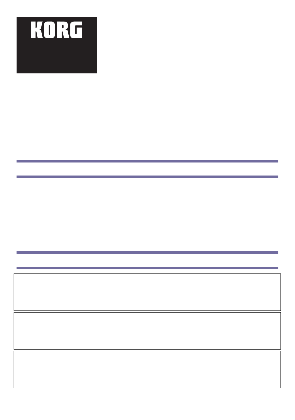
Part listing - Liste des pièces - Teileliste - Elenco delle parti
Before beginning with the installation, please
be sure all the following parts are included
with your kit. Some parts are needed only
when installing the board on a particular
model, but not on others. In addition, you will
need a cross-point screwdriver and a pair of
pliers (not supplied).
Avant de procéder à l'installation, vérifier de
posséder tous les éléments listés ci-dessous. Certaines pièces sont nécessaires uniquement pour
l'installation sur certains modèles, tandis
qu’elles ne le sont pas pour d’autres. Pour le
montage, se munir d'un tournevis cruciforme et
d'une pince (non fournis).
Versichern Sie sich vor Beginn der Installation,
dass alle nachfolgend aufgeführten Teile vorhanden sind. Einige Teile werden bei Installation in bestimmten Modellen benötigt,
während sie in anderen nicht benötigt werden.
Für die Montage sind ein Kreuzschlitzschraubenzieher und eine Zange erforderlich (nicht
im Lieferumfang enthalten).
Prima di iniziare l’installazione, assicuratevi di essere in possesso delle parti elencate. Alcune delle parti sono necessarie solo per l’installazione
della scheda su un particolare modello, ma non sugli altri. Per il montaggio sono richiesti un cacciavite a croce ed un paio di pinze (non forniti).
A
B
G
D
C
E
H
F
Part name / Nom des pièces / Namen der Teile / Nome delle parti Pa1X Pro Pa1X Pa80 Pa60
A Video card / Carte vidéo / Videokarte / Scheda video √√√√× 1
Plastic spacers / Entretoises en plastique / Plastikdistanzstücke / Distanziali in
B
plastica
C Cable holder clip / Ergot serre-câble / Kabelhalterclip / Clip fermacavo √√× 1
Ground cable / Connexion masse / Erdungsanschluss / Cavo connessione
D
massa
Video card cable / Relance carte vidéo / Videokartenkabel / Rilancio scheda
E
video
F Video cable / Câble vidéo / Videokabel / Cavo video × 1
G Nuts / Ecrous / Muttern / Dadi √× 2
2.9 x 9.5 self-threading screw / Vis 2.9 x 9.5 autotaraudeuses / Selbstschnei-
H
dende Schrauben 2.9 x 9.5 / Vite 2.9 x 9.5 autofilettante
Note: The checkmark means the part is needed for the corresponding instrument.
Note : La coche indique que la pièce est nécessaire pour l’instrument correspondant.
Anmerkung: Das Häkchen zeigt an, dass dieses Teil für das jeweilige Instrument benötigt wird.
Nota: Il segno di spunta indica che la parte è necessaria per lo strumento corrispondente.
2
√× 2
√× 1
√× 1
√× 2
Page 3
Installation - Installazione
Pa1X Pro
1. Turn the instrument upside down, and remove the seven
screws (d), to open the cover (c) and gain access to the option
compartment.
Note: Block an y possible acc ess to the inside of the instrument
during installation to prevent any items from falling inside. In
the event something does fall into the instrument, please
immediately contact your nearest Service Center.
Tourner l’instrument et enlever les sept vis (d) pour ouvrir le
capot (c) et accéder au coffret des options.
Note : Pendant l’installation, procéder de manière à empêcher
l’accès à l’interne de l’instrument afin d’éviter que des objets ne
tombent à l’intérieur. Si par malheur quelque chose tombe dans
l’instrument, adressez-vous immédiatement au Service d’Assistance Agréé Korg le plus proche.
Drehen Sie das Instrument mit der Unterseite nach oben und
lösen Sie die sieben Schrauben (d), um den Deckel (c) zu öffnen und Zugang zum Optionsfach zu erhalten.
Anmerkung: Sorgen Sie dafür, dass währ end der I nstallation nichts ins I nnner e des Instruments fallen kann. Sollt e dies dennoc h passieren, wenden Sie sich bitte umgehend an das nächste Korg Kundendienstzentrum.
Ruotate lo strumento, e rimuovete le sette viti (d) per aprire il coperchio (c) e accedere al vano opzioni.
Nota: Impedite ogni possibile accesso all’interno dello strumento, per evitare che degli oggetti possano cadervi dentro. Nel caso questo
dovesse accadere, rivolgetevi immediatamente al più vicino Centro di Assistenza.
d
d
d
c
d
d
d
d
2. As you face the option compartment opening, locate the area
reserved for the video interface, i.e., the one with the two
small vertical spacers and the cable (e), secured by two clips.
Unfasten the cable (e) from the clip (C), and rewire the clip
around the unfastened cable.
Se positionner devant le coffret des options et repérer la zone
réservée à l’interface vidéo qui est identifiée par la présence des
deux entretoises et du câble (e) fixé à l’aide de deux ergots serrecâble. Libérez la partie terminale du câble (e) de l’étau de l’ergot
serre-câble (C) et enrouler l’ergot autour du câble ainsi libéré.
Wenn das Optionsfach vor Ihnen liegt, lokalisieren Sie den für
die Videoschnittstelle vorgesehenen Bereich, in dem sich zwei
vertikale Distanzstücke und das mit zwei Klemmen gesicherte
Kabel (e) befinden. Lösen Sie das Kabel (e) aus der Klemme
(C) und wickeln Sie die Klemme um das gelockerte Kabel.
Ponendovi di fronte al vano opzioni, individuate la zona riservata all’interfaccia video, contraddistinta dalla presenza dei due distanziali e del cavo (e), fissato mediante due fermi. Liberate il terminale
del cavo (e) dalla morsa del fermo (C), e riavvolgete il fermo attorno al cavo sciolto.
e
C
3
Page 4
3. Examine the v ideo interface (A) included with the kit. Note
how the IC board (f) is joined to the support (g) by means of
the two screws (b). Unscrew the two screws (b) to separate
them. You will not need the removed screws (b) and support
(g) for the installation on the Pa1X Pro, nevertheless we suggest to save them for any future use.
Prélever dans la boîte la carte vidéo (A). La regarder attentivement :
la carte (f) est unie au support (g) à l’aide des deux vis (b). Enlever
les deux vis pour séparer les deux pièces. Les vis et le support enlevés
ne sont pas nécessaires pour le montage de la carte dans le Pa1X
Pro ; néanmoins, on conseille de les conserver en lieux sûrs pour
pouvoir éventuellement les réutiliser dans le futur.
Nehmen Sie die Videoschnittstelle (A) aus dem Set. Beachten
Sie bitte, dass die Elektronikkarte (f) mittels zwei Schrauben
(b) an der Halterung (g) befestigt ist. Trennen Sie sie durch
Lösen der beiden Schrauben (b). Die herausgenommenen
Schrauben und die Halterung sind zur Installation der Karte im Pa1X Pro nicht erforderlich. Wir empfehlen jedoch, sie an einem
sicheren Ort aufzubewahren, falls sie wieder einmal benötigt werden sollten.
Prendete la scheda video (A) presente nel kit. Si osservi che la scheda elettronica (f) è unita al supporto (g) mediante le due viti (b). Separateli rimuovendo le due viti (b). Le viti e il supporto rimossi non saranno necessari per l’installazione della scheda su Pa1X Pro, ma vi
consigliamo comunque di riporli in un luogo sicuro e conservarli per future evenienze.
4. Inser t the two plastic spacers (B) into the corresponding screws
on the option compartment cover, as shown in the diagram.
Secure the IC board (f) to the two spacers (B), using the two
self-locking nuts (G). Connect the terminal lug of the cable (e)
and the terminal lug without a ring (F) to the corresponding
connectors on the IC board. Unscrew the screw (b) from the
connector board in the option compartment, then re-insert it
after securing to it the clip (C) included with the accessory kit.
Use the clip to lock the ring of the free cable terminal lug (F).
Connect this terminal to the RCA connector on the connector
board, as shown in the diagram.
Enfiler les deux entretoises en plastique (B) dans les deux vis correspondantes du coffret des options (voir figure ci-contre). Fixer la
carte (f) sur les deux ergots à l’aide des deux écrous autotaraudeurs
(G). Connecter le terminal du câble (e) et le connecteur sans boucle
aux bornes correspondantes de la carte. Enlever la vis (b) de la
carte des connecteurs dans le coffret des options et la remettre après
y avoir fixé l’ergot serre-câble (C) fourni avec le kit des accessoires de l’instrument. Utiliser l’ergot serre-câble pour bloquer la boucle du terminal
libre du câble (F). Brancher le terminal à la borne RCA de la carte des connecteurs (voir figure ci-contre).
Stecken Sie die beiden Plastik-Distanzstücke (B) auf die beiden Schrauben im Deckel des Optionsfaches, wie in der A bbildung gez eigt
wird. Befestigen Sie die IC-Karte (f) mit den beiden selbstsperrenden Schrauben (G) an den beiden Gewindespornen. Verbinden Sie
das Kabelende (e) und den ringlosen Verbinder mit den entsprechenden Verbindern der Elektronikkarte. Entfernen Sie die Schraube
(b) von der Anschlusskarte im Optionsfach und stecken S ie sie wieder ein, nachdem sie mit der im Set enthalt enen Klemme (C) befestigt wurde. Verwenden Sie die Klemme, um den Ring der freien Kabelöse (F) zu befestigen. Verbinden Sie die Kabelöse mit dem
RCA-Verbinder der Anschlusskarte wie in der Abbildung gezeigt wird.
Infilate i due distanziali in plastica (B) nelle due viti corrispondenti nel coperchio del vano opzioni, come mostrato in figura. Fissate la
scheda elettronica (f) ai due speroni mediante i due dadi autobloccanti (G). Collegate il terminale del cavo (e) e il connettore privo di
anello ai connettori corrispondenti della scheda elettronica. Rimuovete la vite (b) dalla scheda connessioni nel vano opzioni, e reinseritela
dopo avervi fissato il fermo (C) compreso nel kit accessori in dotazione allo strumento. Usate il fermo per bloccare l’anello del terminale
libero del cavo (F). Collegate il terminale al connettore RCA della scheda connessioni, come mostrato in figura.
5. Close and secure the compartment cover by reversing the procedure described in step 1.
Refermer le capot du coffret des options et serrer toutes les vis, en procédant dans l’ordre inverse des instructions détaillées au poste 1.
Schließen Sie den Deckel des Optionsfaches, indem Sie die in Punkt 1 angegebenen Arbeitsschritte in umgekehrter Reihenfolge ausführen. Ziehen Sie die Schrauben an.
Chiudete il coperchio del vano opzioni, e stringete tutte le viti, seguendo l’ordine inverso rispetto alle istruzioni contenute al passo 1.
f
B
B
A
e
b
b
b
b
G
f
F
G
g
b+C
4
Page 5
Pa1X
1. Turn the instrument upside down, and remove the eight
screws (d), to open the cover (c) and gain access to the option
compartment.
Note: Block any possible access to the inside of the instrument
during installation to prevent any items from falling inside. In
the event something does fall into the instrument, please
immediately contact your nearest Service Center.
Tourner l’instrument et enlever les huit vis (d) pour ouvrir le
capot (c) et accéder au coffret des options.
Note : Pendant l’installation, procéder de manière à empêcher
l’accès à l’interne de l’instrument afin d’éviter que des objets ne
tombent à l’intérieur. Si par malheur quelque chose tombe dans
l’instrument, adressez-vous immédiatement au Service d’Assistance Agréé Korg le plus proche.
Drehen Sie das Instrument mit der Unterseite nach oben und
lösen Sie die acht Schrauben (d), um Zugang zum Optionsfach
zu erhalten.
Anmerkung: Sorgen Sie dafür, dass während der Installation nichts ins Innere des Instruments fallen kann. Sollte dies dennoch passieren, wenden Sie sich bitte umgehend an das nächste Korg Kundendienstzentrum
Ruotate lo strumento, e rimuovete le otto viti (d) per aprire il coperchio (c) e accedere al vano opzioni.
Nota: Impedite ogni possibile accesso all’interno dello strumento, per evitare che degli oggetti possano cadervi dentro. Nel caso questo
dovesse accadere, rivolgetevi immediatamente al più vicino Centro di Assistenza.
2. As you face the option compartment opening, locate the area
reserved for the video interface, i.e., the one with the two small
vertical spacers, the cable (e), secured by two clips, and the
cable (F), secured by the clip (C). Note how the clip (C) is
secured to one of the two vertical spacers by means of the
screw (b). Unscrew the screw (b) and remove the clip (C).
Then unfasten the cable (e) from the clip (C), as shown in the
diagram. Save the screw and the clip, you will need them to
complete the video interface installation.
Se positionner devant le coffret des options et repérer la zone réservée à l’interface vidéo qui est identifiée par la présence des deux
entretoises verticales et du câble (e) fixé à l’aide de deux ergots
serre-câble et du câble (F) fixé à l’aide de l’ergot (C). Regarder
attentivement : l’ergot serre-câble (C) est fixé à l’une des deux
entretoises verticales à l’aide de la vis (b). Enlever la vis (b) et
l’ergot serre-câble (C) ; ensuite libérer la partie terminale du
câble (e) de l’étau de l’ergot (C) - voir la figure ci-contre. Garder
à portée de main la vis et l’ergot ôtés car ils servent successivement pour l’installation de l’interface vidéo.
Wenn das Optionsfach vor Ihnen liegt, lokalisieren Sie den für die Videoschnittstelle vorgesehenen Bereic h, in dem sich zwei vertikale
Distanzstücke, das mit zwei Klemmen gesicherte Kabel (e) und das mit der Klemme (C) gesicherte Kabel (f ) befinden. Beachten Sie,
dass die Klemme (C) an einem der beiden vertikalen Distanzstücke mit der Schraube (b) befestigt ist. Lösen Sie die Schraube (b) und
entfernen Sie die Klemme (C). Ziehen Sie das Kabel (e) aus der Klemme (C) wie in der Abbildung gezeigt wird. Bewahren Sie die
Schraube und die Klemme sorgfältig auf, da Sie diese noch zur Installation der Videoschnittstelle benötigen.
Ponendovi di fronte al vano opzioni, individuate la zona riservata all’interfaccia video, contraddistinta dalla presenza delle due colonnine,
del cavo (e), fissato mediante due fermi, e del cavo (F), fissato mediante il fermo (C). Si osservi come il fermo (C) sia fissato ad una delle
due colonnine per mezzo della vite (b). Rimuovete la vite (b) e il fermo (C), poi liberate il cavo (e) dalla morsa del fermo (C), come
mostrato nell’illustrazione. Riponente la vite e il fermo rimossi, che vi serviranno più avanti per l’installazione dell’interfaccia video.
d
d
d
b+C
d
d
c
d
d
F
e
C
d
5
Page 6

3. Note how the IC board (f) is joined to the support (g) by
means of the two screws (b). Unscrew the two screws (b) to
separate them. You will not need the removed support (g) for
the installation on the Pa1X, nevertheless we suggest to save
them for any future use. On the contrary, the removed screws
will be needed in the following step.
Regarder attentivement : la carte (f) est unie au support (g) à
l’aide des deux vis (b). Enlever les deux vis pour séparer les deux
pièces. Le support enlevé n’est pas nécessaire pour le montage de
la carte dans le Pa1X ; néanmoins, on conseille de le conserver en
lieux sûrs pour pouvoir éventuellement le réutiliser dans le futur.
Garder les vis à portée de main car elles sont nécessaires au poste
suivant.
Beachten Sie, dass die IC-Karte (f) mit den beiden Schrauben
(b) an der Halterung (g) befestigt ist. Obwohl Sie die entfernte
Halterung (g) für die Installation im Pa1X nicht mehr benötigen, empfehlen wir, diese für einen eventuellen späteren Gebrauch an einem sicheren Ort aufzubewahren. Die entfernten Schrauben
sind hingegen für den nächsten Arbeitsschritt erforderlich.
Si osservi che la scheda elettronica (f) è unita al supporto (g) mediante le due viti (b). Separateli rimuovendo le due viti (b). Il supporto
rimosso non sarà necessario per l’installazione della scheda su Pa1X, ma vi consigliamo comunque di riporlo in un luogo sicuro e conservarlo per future evenienze. Al contrario, le viti rimosse si renderanno necessarie al passo seguente.
4. Secure the IC board (f ) to the two vertical spacers using the
two screws (b), previously removed. Please remember to reinsert the clip (C) at its original position. Connect the terminal lug of the cable (F) to the corresponding connector on the
IC board. Secure the cable to the clip (C). Finally, connect the
cable (e) to the IC board, and secure it using the previously
loosened clip (C).
Fixer la carte (f) aux deux entretoises verticales à l’aide des deux
vis (b) vues plus haut : se rappeler d’insérer de nouveau l’ergot
(C) sur sa position originale. Connecter le terminal (F) à la
borne correspondante de la carte. Fixer le câble (e) à l’ergot
serre-câble (C). Pour finir, connecter le câble (e) à la carte et le
fixer en serrant de nouveau l’ergot serre-câble (C) préalablement
desserré.
Befestigen Sie die IC-Karte (f) mit den beiden zuvor entfernten Schrauben (b) an den beiden vertikalen Distanzstücken.
Denken Sie bitte daran, die Klemme (C) wieder in ihrer ursprünglichen Position einzusetz en. Verbinden Sie die Kabelöse (F) am entsprechenden Verbinder der IC-Karte. Befestigen Sie das Kabel an der Klemme (C). Schließen Sie anschließend das Kabel (e) an der
IC-Karte an und sichern Sie es mit Hilfe der zuvor gelösten Klemme (C).
Fissate la scheda elettronica (f) alle due colonnine mediante le due viti (b) rimosse in precedenza, ricordando di inserire nuovamente il
fermo (C) alla posizione originale. Collegate il terminale (F) al connettore corrispondente della scheda elettronica. Fissate il cavo al fermo
(C). Infine, collegate il cavo (e) alla scheda elettronica, e fissatelo stringendo nuovamente il fermo (C) allentato in precedenza.
f
f
e
b
A
b
b
b
b+C
F
b
C
g
5. Close and secure the compartment cover by reversing the procedure described in step 1.
Refermer le capot du coffret des options et serrer toutes les vis, en procédant dans l’ordre inverse des instructions détaillées au paragraphe 1.
Schließen Sie den Deckel des Optionsfaches, indem Sie die in Punkt 1 angegebenen Arbeitsschritte in umgekehrter Reihenfolge ausführen. Ziehen Sie die Schrauben an.
Chiudete il coperchio del vano opzioni, e stringete tutte le viti, seguendo l’ordine inverso rispetto alle istruzioni contenute al passo 1.
6
Page 7

Pa80
Note: To use the VIF3, your Pa80 must be fitted with the operating system version 1.5 or higher. You can see which version of the operating
systems is installed in your Pa80 by keeping the SHIFT button pressed, and pressing the ENTER and EXIT buttons together. The operating
system version number will appear in the display . Press EXIT to close the message window . You can download the latest version of the operating system from www.korgpa.com.
Note : Pour utiliser la carte VIF3, le Pa80 doit être doté du système opérationnel 1.5 ou supérieur. Maintenez enfoncé le bouton SHIFT et appuyez
simultanément sur ENTER et sur EXIT pour afficher la version du système opérationnel installée sur votre Pa80. Appuyez sur EXIT pour quitter
cette fenêtre de message. Vous pouvez télécharger la version la plus récente du système opérationnel directement du site www.korgpa.com.
Anmerkung: Zur Verwendung der VIF3 Board, muss das Betriebssystem 1.5 oder Folgeversionen installiert sein. Dazu ist der SHIIFT Taster
gedrückt zu halten und gleichzeitig sind die Taster ENTER und EXIT zu drücken. Die Nummer der Version erscheint auf dem Display.
Drücken Sie EXIT, um dieses Anzeigefenster wieder zu schließen. Sie können die neueste Version des Betriebssystems aus dem Internet
(www.korgpa.com) heruntergeladen werden.
Nota: Per utilizzare la scheda VIF3, nel Pa80 deve essere installato il sistema operativo 1.5 o superiore. Per controllare la versione di sistema operativo installata nel vostro Pa80, tenete premuto il tasto SHIFT e premete insieme ENTER ed EXIT. Il numero di versione del sistema operativo
installato appare nel display. Premete EXIT per chiudere la finestra di dialogo. Potete prelevare la più recente versione di sistema operativo dal
sito www.korgpa.com.
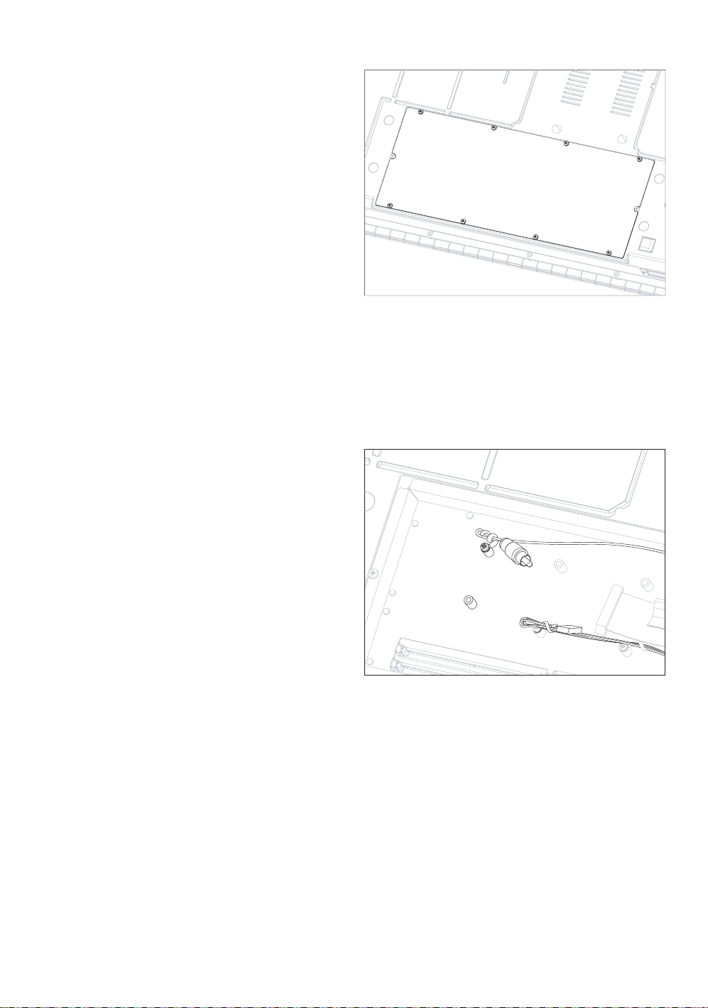
1. Face the back of the instrument, and loosen the two
screws (H) to remove the plate (a). Keep the screws in
a safe place, to be used again later.
Se positionner devant la face arrière de l’instrument,
avec le logement de la carte vidéo devant soi. Enlever les
deux vis (H) pour libérer la plaquette (a). Conserver les
vis pour les réutiliser successivement.
Drehen Sie das Instrument so um, dass der Videokarten Steckplatz sich vor Ihnen befindet. Entfernen Sie
die beiden Schrauben (H), um das Plättchen (a) zu
lockern. Verwahren Sie die Schrauben, da Sie diese
anschließend wieder benötigen.
Portatevi sul retro dello strumento, in modo da trovarvi
di fronte all’alloggiamento per la scheda video. Rimuovete le due viti (H) per liberare il piastrino (a). Conservate le viti, che vi serviranno
in seguito.
HHa
2. After removing the plate, loosen the nut (G) with the
help of a pair of pliers. Remove the ground cable (D)
from the bolt fixed onto the back side of the plate (a),
and remove the cable (E) from the clip (C). At this
point, you can completely remove the plate (a). Reposition the clip (C) and the nut (G) to the bolt on the
plate (a), then save the removed parts in a safe place
for future servicing of the video interface.
Après avoir libéré la plaquette, enlever l’écrou (G) à
l’aide des pinces, de manière à faire glisser le câble de
masse (D) maintenu par le cavalier fileté et libérer le
câble (E) de la clip (C). Maintenant, enlever la plaquette
(a). Placer de nouveau la clip (C) et l’écrou (G) sur le
cavalier de la plaquette (a) et les garder en lieu sûr, de
manière à pouvoir les réutiliser en cas d’assistance à la carte vidéo.
Nach dem Lockern des Plättchens entfernen Sie die Mutter (G) mittels einer Zange, um das Kabel aus dem Gewindesporn (D) herausziehen zu können. Kabel (E) von der Klemme (C) abziehen. Nun kann das Plättchen (a) abgenommen werden. Stecken Sie die
Klemme (C) und die Mutter (G) wieder auf den Sporn des Plättchens (a). Verwahren Sie das Ganze an einem sicheren Ort, um es im
Falle einer Reparatur der Videokarte wiederverwenden zu können.
Dopo aver liberato il piastrino, rimuovete il dado (G) con l’aiuto di un paio di pinze, poi sfilate il cavo di massa (D) dallo sperone filettato
posto sul retro del piastrino (a), e liberate il cavo (E) dalla clip (C). A questo punto potete rimuovere il piastrino (a). Riposizionate la clip
(C) e il dado (G) sullo sperone del piastrino (a), e riponete il tutto in un luogo sicuro, in modo da poterlo riutilizzare in caso di assistenza
alla scheda video.
D
G
a
C
E
7
Page 8

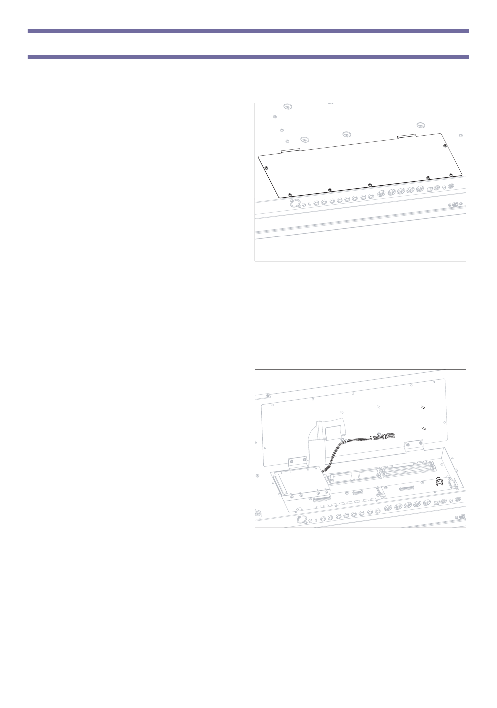
3. Take the video board (A), and remove the screw (b).
Keep it in a safe place, to use it again in the following
step.
Prendre la carte vidéo (A) et enlever la vis (b) en la mettant de côté afin de pouvoir la réutiliser ultérieurement.
Nehmen Sie die Videokarte (A) und entfernen Sie die
Schraube (b). Ver wahren Sie sie, da sie beim nächsten
Arbeitsschritt benötigt wird.
Prendete la scheda video (A), ed estraete la vite (b),
tenendola da parte per riutilizzarla nel passo successivo.
b
A
4. Fasten the screw (b) at its original position, using it to
fix the terminal lug of the cable (D). Place the cable so
that it can’t damage the video board (A) components.
During this work, be sure not to let the cable (E) slide
inside the instrument.
Visser à nouveau la vis (b), enlevée au poste 3, sur sa
position originale, en bloquant la boucle du câble (D),
qu’il faut positionner de manière à ne pas endommager
les composants de la carte vidéo (A). Attention ! Le câble
(E) ne doit pas tomber à l’interne de l’instrument pendant cette opération.
Drehen Sie die soeben gelockerte Schraube (b) wieder
ihren ursprünglichen Sitz ein und befestigen Sie dabei
die Kabelöse (D) so, dass die Bauteile der Videokarte
(A) nicht beschädigt werden. Achten Sie darauf, dass das Kabel (E) nicht ins Innere des Instruments rutscht.
Riavvitate la vite (b), appena rimossa, nella sua posizione originale, bloccandoci l’occhiello del cavo (D), che va posizionato in modo da
non arrecare danno ai componenti della scheda video (A). Durante questa operazione, attenzione a non far scivolare il cavo (E) all’interno
dello strumento.
E
D
b
A
5. Connect the cable (E) to the video board connector.
The connector must be inserted along the guided
direction.
Connecter le câble (E) à la borne de la carte vidéo, dans
la seule direction possible (sur des positions différentes, la
borne oppose une résistance à l’insertion).
Stecken Sie das Kabel (E) in den Verbinder der Videokarte ein. Es gibt nur eine Einsteckposition (in anderen Positionen lässt sich der Verbinder nicht
einstecken).
Collegate il cavo (E) al connettore della scheda video
nell’unico verso possibile (in posizioni diverse il connettore oppone resistenza all’inserimento).
E
A
8
Page 9

6. Bend up the terminal lug of the cable (D), to avoid its
touching any of the board’s components.
Plier la boucle du câble vers le haut (D), en faisant toujours très attention : le câble ne doit pas entrer en contact
avec les composants de la carte vidéo.
Biegen Sie die Kabelöse (D) so nach oben, dass kein
Kontakt mit den Bauteilen der Videokarte entsteht.
Piegate l’occhiello del cavo (D) verso l’alto, in modo che
non faccia contatto con i componenti della scheda video.
D
D
7. After connecting all cables correctly, carefully insert
the video board (A) in the slot located on the back of
the instrument, previously opened. The electronic
components must be faced upwards.
Après avoir correctement connecté tous les câbles, insérer
avec grand soin la carte vidéo (A) dans le logement prévu
sur la face arrière de l’instrument, qui avait été précédemment ouvert. Les composants électroniques de la
carte doivent être dirigés vers le haut.
Nach korrektem Anschluss aller Kabel stecken Sie die
Videokarte (A) ganz vorsichtig in ihren Sitz auf der
zuvor geöffneten Rückseite des Instruments ein. Die
elektronischen Bauteile des Board müssen nach oben
gerichtet sein.
Dopo aver collegato tutti i cavi nel modo corretto, inserite con molta cautela la scheda video (A) nell’alloggiamento, situato nel retro dello
strumento, aperto in precedenza. I componenti elettronici della scheda devono essere rivolti vero l’alto.
A
8. Finally, attach the video board (A) to the instrument
using the two screws (H) previously removed.
Pour finir, fixer la carte vidéo (A) sur l’instrument à
l’aide des deux vis (H) précédemment enlevées.
Befestigen Sie die Videokarte (A) mit den beiden zuv or
entfernten Schrauben (H) im Instrument.
Fissate infine la scheda video (A) allo strumento con le
due viti (H) rimosse in precedenza.
HHHHHHA
9
Page 10

Pa60
Warning: The card must be installed by a Korg Authorized Service Center. Korg is not responsible for any damage or injury caused by
incorrect installation of this card by unauthorized personnel.
Attention : L’installation de la carte doit être effectuée par un Centre d'Assistance Agréé Korg. Korg décline toutes responsabilités envers des
dommages aux personnes ou aux choses provoqués par l'installation de la carte de la part de personnes non autorisées.
Achtung: Die Installation der Karte darf nur von einem autorisierten Korg-Kundendienstzentrum vorgenommen werden. Korg übernimmt keine Haftung für Sach- oder Personenschäden bei Installation der Karte durch nicht autorisierte Personen.
Attenzione: L’installazione della scheda va effettuata presso un Centro di Assistenza Autorizzato Korg. Korg non si assume responsabilità
per danni a cose o persone causati dall’installazione della scheda da parte di personale non autorizzato.
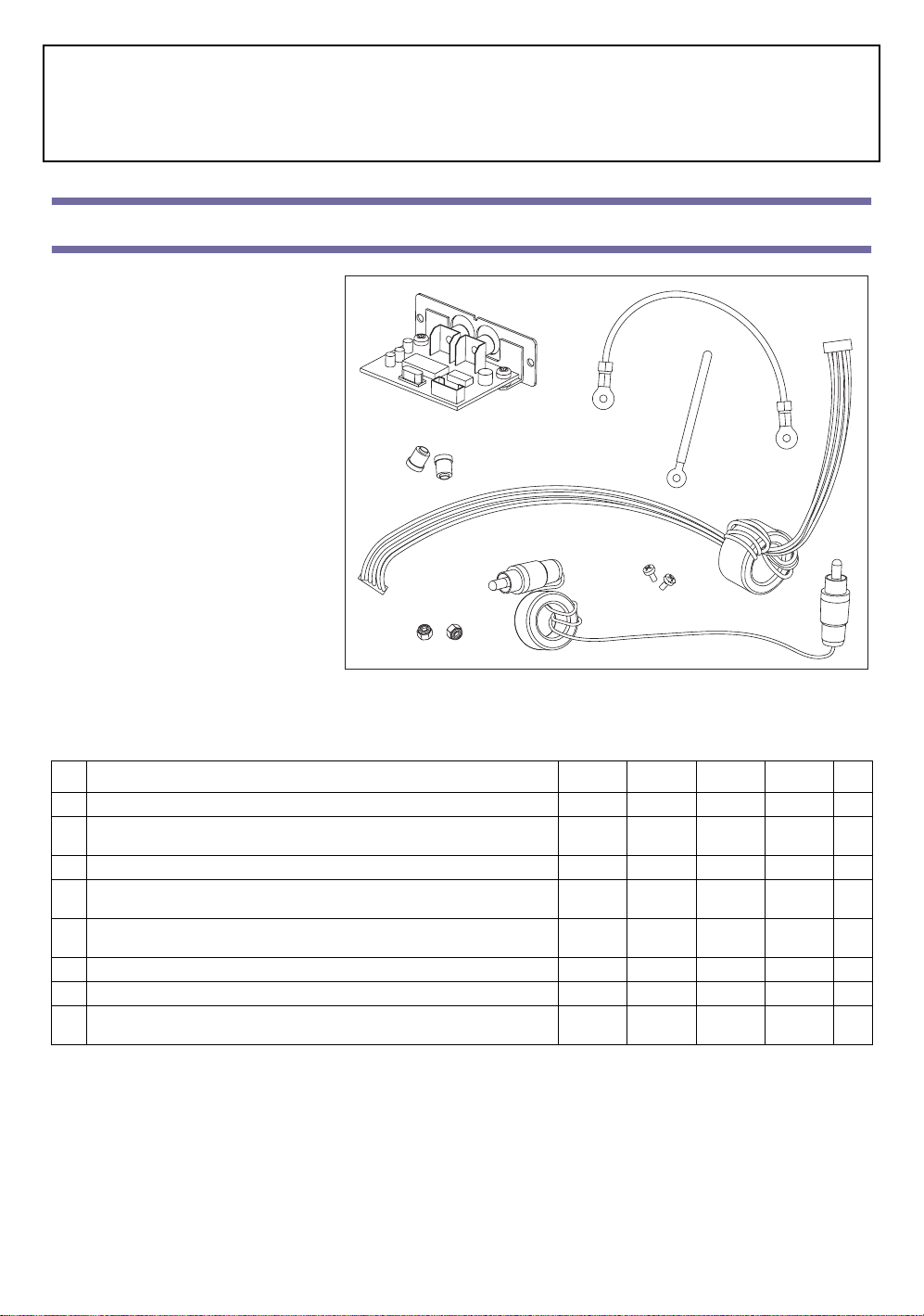
1. Access the inside of the instrument and remove the
connector board, by following the opening and disassembling instruction found in the “Pa60 Service Manual” (code MAN0002008). Then remove the screw of
the Dial in the lower right corner, to connect the cable
holder clip (C). Connect the video card cable (E) to the
corresponding connector on the motherboard, and fix
the ferrite using the clip.
Accéder à l'intérieur de l'instrument et enlever la carte
des connecteurs, en procédant conformément aux instructions de démontage illustrées dans le “Pa60 Service
Manual” (code MAN0002008). L'opération ayant été
exécutée, enlever la vis du Dial située en bas à droite pour
y appliquer l'ergot serre-câble (C). Brancher la relance de
la carte vidéo (E) à son correspondant connecteur sur la
carte mère et bloquer sa patte à l'ergot précédemment
fixé.
Öffnen Sie das Instrument und entfernen Sie die Verbinderkarte unter Befolgung der Demontageanweisungen im Handbuch “Pa60 Service Manual”
(Artikelnummer MAN0002008). Entfernen Sie
anschließend die Schraube des Rades rechts unten, um
dort den Kabelhalterclip (C) anzubringen. Schließen
Sie das Kabel der Videokarte (E) an den entsprechenden Verbinder der Hauptplatine an. Stecken Sie den
Ferritstreifen in den soeben angebrachten Clip ein.
Accedete all’interno dello strumento e rimuovete la scheda dei connettori, seguendo le operazioni di disassemblaggio illustrate nel “Pa60
Service Manual” (codice MAN0002008). Fatto questo, rimuovete la vite del Dial in basso a destra, per applicarvi la clip fermacavo (C).
Collegate il rilancio della scheda video (E) al relativo connettore della scheda madre, e bloccatene la ferrite nella clip appena fissata.
E
E
C
10
Page 11

2. Remove the cover from the video card opening on the
back panel of the instrument, by breaking the plastic
tabs, as shown by the arrow in the diagram.
Enlever le capot de l'ouverture en face arrière de l'instrument en cassant les fixations, comme indiqué par la flèche dans la figure.
Entfernen Sie die Abdeckung der Öffnung auf der
Rückseite des Instruments. Hierzu sind die Befestigungsstege aufzubrechen (siehe Pfeil in der nebenstehenden Zeichnung).
Rimuovete il coperchio dell’apertura nel retro dello strumento rompendone i fissaggi, come indicato dalla freccia
nella figura a lato.
3. Remove the screw from the video card (A) as shown in
the diagram, to connect the ground cable (D). Fasten
the screw at its original position, to fix the cable in
place.
Sur la carte vidéo (A), enlever la vis indiquée dans la
figure pour pouvoir y brancher le câble de la masse (D).
Réintroduire la vis pour bloquer le câble.
Entfernen Sie die in der Zeichnung angezeigte
Schraube aus der Videokarte (A), um dort das
Erdungskabel (D) anschließen zu können. Drehen Sie
die Schraube wieder ein, um das Kabel an seinem Sitz
zu halten.
Rimuovete dalla scheda video (A) la vite indicata in
figura, per potervi collegarvi il cavo di massa (D). Reinserite la vite per bloccare il cavo in sede.
A
D
4. Pass the cable (E) through the (previously opened) slot
on the back panel, and connect it to the video card (A).
The connector must be inserted along the guided
direction (when trying with a different direction, the
connector cannot slide in).
Enfiler la relance (E) à travers l'ouverture en face arrière
précédemment ouverte et la brancher à la carte vidéo (A).
La direction d'insertion est obligée (c'est à dire que le
connecteur est doté de détrompeur et oppose une résistance dans des positions différentes).
Schieben Sie das Videokartenkabel (E) durch die zuvor
aufgebrochene Öffnung und schließen Sie es an die
Videokarte (A) an. Die Einsteckrichtung ist vorgegeben (falsch positionierter Verbinder lässt sich nicht
einstecken).
E
A
11
Page 12

Fate passare il rilancio (E) attraverso l’apertura nel pannello posteriore aperta in precedenza, e collegatelo alla scheda video (A). Il verso di
inserimento è obbligato (in posizioni diverse il connettore oppone resistenza).
5. Bend up the terminal lug of the cable (D), to avoid its
touching any of the video board’s components.
Plier vers le haut la boucle du câble (D), de manière à ce
qu'aucun contact ne se crée avec les composants de la
carte vidéo.
Biegen Sie die Schlaufe des Kabels (D) nach oben,
damit es die Bauteile der Videokarte nicht berührt.
Piegate verso l’alto l’occhiello del cavo (D), in modo che
non faccia contatto con i componenti della scheda video.
D
D
6. Carefully inser t the video board (A) in the slot located
on the back of the instrument, previously opened. The
electronic components must be facing up.
Insérer avec beaucoup de précaution la carte vidéo (A)
dans l'emplacement, précédemment ouvert, situé en face
arrière de l'instrument. Les composants électroniques
doivent être tournés vers le haut.
Stecken Sie die Videokarte (A) vorsichtig in ihren
zuvor geöffneten Sitz auf der Rückseite des Instruments ein. Die elektronischen Bauteile müssen nach
oben gerichtet sein.
Inserite con molta cautela la scheda video (A) nell’alloggiamento, aperto in precedenza, situato nel retro dello
strumento. I componenti elettronici devono essere rivolti verso l’alto.
A
7. Finally, attach the video board (A) to the instrument
using the two screws (H) supplied with the kit.
Fixer la carte vidéo (A) à l'instrument à l'aide des deux
vis (H) fournies.
Befestigen Sie die Videokarte (A) mit Hilfe der beiden
mitgelieferten Schrauben (H) im Instrument.
Fissate la scheda video (A) allo strumento utilizzando le
due viti (H) presenti nel kit.
H A H
12
Page 13

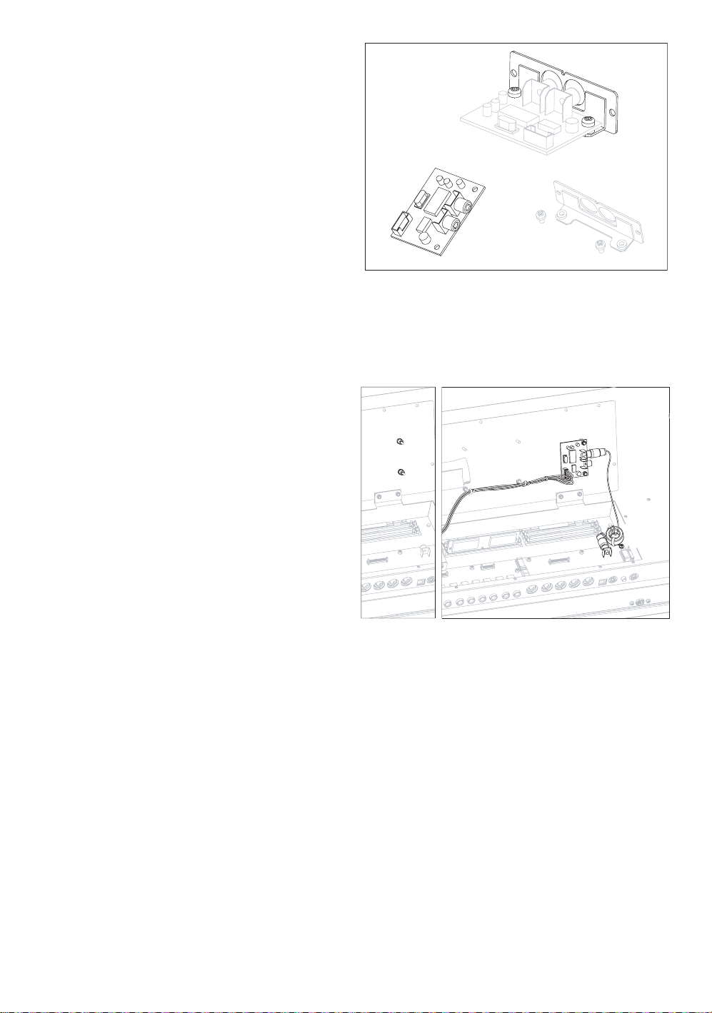
8. Remove the fastening screw on the connector board
(shown in the diagram), and use it to fasten the free
terminal lug of the ground cable (D). Reinsert the connector board in the instrument, by following the
instructions found in the “Pa60 Service Manual”. Reassemble the instrument, by following in the reverse
order the instructions found in the “Pa60 Service Manual” for opening and disassembling. Remember to use
the cable holder clip (shown in the diagram by the
pointing arrow) to fasten the cable (E) to the other
cables.
Enlever la vis de fixation de la carte des connecteurs illustrée dans la figure et l'utiliser pour bloquer la boucle libre
du câble de la masse (D). Réintroduire la carte des connecteurs dans l'instrument en procédant aux opérations
détaillées dans le “Pa60 Service Manual”. Refermer l'instrument en effectuant dans l'ordre inverse les opérations
détaillées dans le “Pa60 Service Manual” ; utiliser l'ergot
serre-câble (indiqué par la flèche dans la figure) pour bloquer la relance (E) aux autres relances.
Entfernen Sie die Befestigungsschraube aus der in der
Abbildung gezeigten Verbinderkarte und verwenden
Sie sie zur Befestigung der freien Schlaufe des Erdungskabels (D). Stecken Sie die Verbinderkarte wieder in
das Instrument ein und befolgen Sie hierzu die Anweisungen des Handbuches “Pa60 Service Manual”. Schließen Sie das Instrument wieder, indem Sie die im “Pa60 Service Manual” beschriebenen Arbeitsschritte in umgekehrter Reihenfolge
ausführen. Benutzen Sie den Kabelhalterclip (siehe Pfeil in der Abbildung), um das Videokabel (E) mit den anderen Kabeln zusammenzuhalten.
Rimuovete la vite di fissaggio della scheda connettori mostrata in figura, e usatela per bloccare l’occhiello libero del cavo di massa (D).
Reinserite la scheda connettori nello strumento, seguendo le istruzioni riportate nel “Pa60 Service Manual”. Richiudete lo strumento
seguendo al contrario le istruzioni del “Pa60 Service Manual”, ricordandovi di usare la clip fermacavo (indicata in figura dalla freccia) per
bloccare il rilancio (E) assieme agli altri rilanci.
E
D
13
Page 14

Connections and setup - Connexion et programmation - Anschluss und
Konfiguration - Collegamento e configurazione
Pa1X/Pa1X Pro
1. Connect the instrument’s video output to the video input of the television set.
Depending on the type of television set, you can use a cable of the ty pe “RCA-toRCA” (if the television set is equipped with a Video Composite input), or “RCAto-SCART” (if the television set is equipped with a SCART connector). You can
buy the needed cables at a store that sells television equipment.
Connecter la sortie vidéo de l’instrument à l’entrée vidéo du poste de télévision. Selon
le type de poste de télévision, on peut utiliser un câble du type “de RCA à RCA” (si le
poste est doté d’entrée Vidéo Composite) ou “de RCA à SCART” (si le poste est doté de
prise SCART). Voir chez les revendeurs d’appareils TV les câbles nécessaires.
Verbinden Sie den Videoausgang des Instruments an den Ausgang des Fernsehers.
Je nach Fernsehermodell können Sie ein Kabel des Typs “von RCA zu RCA” (wenn
der Fernseher mit einem mehrteiligen Videoausgang versehen ist) oder des Typs
“von RCA zu SCART” verwenden (wenn der Fernseher mit einem SCARTAnschluss versehen ist). Die entsprechenden Kabel können in jedem Fernsehfachgeschäft erworben werden.
Collegate l’uscita video dello strumento all’ingresso video del televisore. A seconda del
tipo di televisore, potete usare un cavo di tipo “da RCA ad RCA” (se il televisore è
dotato di ingresso Video Composito), o “da RCA a SCART” (se il televisore è dotato
di presa SCART). I cavi necessari sono reperibili presso qualsiasi negozio di televisori.
RCA
RCA
SCART
2. Turn the instrument on, and press the GLOBAL button to gain access to the Glo-
bal edit mode. Go to the “Video Interface: Video Out” page, and select the video standard (PAL or NTSC) depending to the installed
video board (VIF3-PAL or VIF3-NTSC).
Mettre l’instrument sous tension et appuyer sur GLOBAL pour accéder à l’environnement Global. Afficher page “Video Interface: Video
Out” et sélectionner le standard vidéo PAL ou NTSC, en fonction de la carte installée (VIF3-PAL ou VIF3-NTSC).
Schalten Sie das Instrument ein und drücken Sie GLOBAL, um die Global-Umgebung aufzurufen. Steuern Sie die “Video Interface:
Video Out” Seite an und selektieren Sie den Videostandard PAL oder NTSC, je nachdem, welche Karte installiert wurde (VIF3-PAL
oder VIF3-NTSC).
Accendete lo strumento, e premete GLOBAL per accedere all’ambiente Global. Selezionate la pagina “Video Interface: Video Out” e selezionate lo standard video PAL o NTSC, a seconda della scheda installata (VIF3-PAL o VIF3-NTSC).
3. Select the “Write Global-Global Setup” command from the page menu to save the settings in memory. The Write Global-Global
Setup dialog box will appear. Press OK to confirm.
Dans le menu de la page, sélectionner la commande “Write Global-Global Setup” pour sauvegarder les réglages dans la mémoire. L’écran
affiche la boîte de dialogue Write Global-Global Setup. Appuyer sur OK pour confirmer
Selektieren Sie den Befehl “ Write Global-Global Setup ” aus dem Seitenmenü, um die Einstellungen zu speichern. Daraufhin erscheint
das Dialogfenster Write Global-Global Setup. Drücken Sie OK zur Bestätigung .
Per salvare le impostazioni in memoria, selezionate il comando “Write Global-Global Setup”. Apparirà la finestra di dialogo Write GlobalGlobal Setup. Premete il tasto OK nel display per confermare.
4. Turn the television set on, and tune it on the AV1 or AV2 input.
Allumer le poste de télévision et le régler sur les entrées AV1 ou AV2.
Schalten Sie den Fernseher ein und wählen Sie den Video-Kanal AV1 oder AV2.
Accendete il televisore, e sintonizzatevi sull’ingresso AV1 o AV2.
14
Page 15

5. In the same page of the Global, use the Colors parameter to choose the preferred set of colors for the lyrics and the background.
Toujours dans la page Global, utiliser le paramètre Colors pour sélectionner les couleurs préférées pour le texte et le fond.
Verwenden Sie den Parameter Colors auf der Global-Seite zur Auswahl der gewünschten Farbzusammenstellungen für den Text und
den Hintergrund.
Nella stessa pagina del Global, usate il parametro Colors per scegliere l’abbinamento di colori preferito per testo e sfondo.
Pa80/Pa60
1. Connect the instrument’s video output to the video
input of the television set. Depending on the type of
television set, you can use a cable of the type “RCA-t oRCA” (if the television set is equipped with a Video
Composite input), or “RCA-to-SCART” (if the television set is equipped with a SCART connector). You
can buy the needed cables at a store that sells television equipment.
Connecter la sortie vidéo de l’instrument à l’entrée vidéo
du poste de télévision. Selon le type de poste de télévision, on peut utiliser un câble du type “de RCA à RCA”
(si le poste est doté d’entrée Vidéo Composite) ou “de
RCA à SCART” (si le poste est doté de prise SCART).
Voir chez les revendeurs d’appareils TV les câbles
nécessaires.
Verbinden Sie den Videoausgang des Instruments an
den Ausgang des Fernsehers. Je nach Fernsehermodell können Sie ein Kabel des Typs “von RCA zu RCA” (wenn der Fernseher mit
einem mehrteiligen Videoausgang versehen ist) oder des Typs “von RCA zu SCART” verwenden (wenn der Fernseher mit einem
SCART-Anschluss versehen ist). Die entsprechenden Kabel können in jedem Fernsehfachgeschäft erworben werden.
Collegate l’uscita video dello strumento all’ingresso video del televisore. A seconda del tipo di televisore, potete usare un cavo di tipo “da
RCA ad RCA” (se il televisore è dotato di ingresso Video Composito), o “da RCA a SCART” (se il televisore è dotato di presa SCART). I
cavi necessari sono reperibili presso qualsiasi negozio di televisori.
RCA
RCARCA
RCA
SCART
2. Turn the instrument on, and press the GLOBAL button to gain access to the Global edit environment. Go to “Page 3 - Video Inter-
face” and select the video standard (PAL or NTSC) depending to the installed video board (VIF3-PAL or VIF3-NTSC).
Mettre l’instrument sous tension et appuyer sur GLOBAL pour accéder à l’environnement Global. Afficher “Page 3 - Interface Vidéo” et
sélectionner le standard vidéo PAL ou NTSC, en fonction de la carte installée (VIF3-PAL ou VIF3-NTSC).
Schalten Sie das Instrument ein und drücken Sie GLOBAL, um die Global-Umgebung aufzurufen. Steuern Sie die “Pagina 3 - Video
Interface” an und selektieren Sie den Videostandard PAL oder NTSC, je nachdem, welche Karte installiert wurde (VIF3-PAL oder
VIF3-NTSC).
Accendete lo strumento, e premete GLOBAL per accedere all’ambiente Global. Raggiungete “Pagina 3 - Video Interface” e selezionate lo
standard video PAL o NTSC, a seconda della scheda installata (VIF3-PAL o VIF3-NTSC).
3. Press the WRITE button to save the settings in memory. The Write Global window appears. P r ess one of A VOLUME/VALUE buttons
(Global), then press ENTER/YES to confirm.
Pour sauvegarder les programmations mémorisées, appuyer sur WRITE. L’écran affiche la fenêtre Write Global. Appuyer sur l’un des boutons VOLUME/VALUE A.
Zum Speichern der vorgenommenen Einstellungen drücken Sie WRITE. Daraufhin erscheint das Fenster Write Global. Drücken Sie
einen der Taster VOLUME/VALUE A und ENTER/YES zur Bestätigung.
Per salvare le impostazioni in memoria, premete WRITE. Appare la finestra Write Global. Premete uno dei tasti VOLUME/VALUE A
(Global) e premete ENTER/YES per confermare.
15
Page 16

4. Turn the television set on, and tune it on the AV1 or AV2 input.
Allumer le poste de télévision et le régler sur les entrées AV1 ou AV2.
Schalten Sie den Fernseher ein und wählen Sie den Video-Kanal AV1 oder AV2.
Accendete il televisore, e sintonizzatevi sull’ingresso AV1 o AV2.
5. In the same page of the Global, use the Colors parameter to choose the preferred set of colors for the lyrics and the background. The
Setup #6 allows you to see in the background a picture coming from a video recorder connected between Pa80 and television set.
Toujours dans la page Global, utiliser le paramètre Colors pour sélectionner les couleurs préférées pour le texte et le fond. Setup #6 permet
d’avoir en tant que fond l’image en provenance d’un magnétoscope connecté entre le Pa80 et le poste de télévision.
Verwenden Sie den Parameter Colors auf der Global-Seite zur Auswahl der gewünschten Farbzusammenstellungen für den Text und
den Hintergrund. Mit Setup #6 können Sie als Hintergrund das Bild eines Videogeräts selektieren, das zwischen das Pa80 und den
Fernseher angeschlossen ist.
Nella stessa pagina del Global, usate il parametro Colors per scegliere l’abbinamento di colori preferito per testo e sfondo. Il Setup #6 permette di avere come sfondo l’immagine proveniente da un videoregistratore collegato fra Pa80 e televisore.
© 2003 Korg Italy SpA
16
 Loading...