

Page 1
4E
Page 2

Page 3
BG
PG
1 2 3
1 2 3
☞ p. ■ , ☞
■ , ☞
■ , ☞■ . ■
■
Boldface type
About this manual
Parameter values are printed in boldface type.
Content that is of particular importance is also printed in
This “Parameter Guide” contains explanations and other
information regarding the operations of the parameters and
settings on this instrument. The explanations are organized
by mode, page, and tab. Explanations and other information
on the effects and their parameters are also provided for
each effect.
Refer to this guide when an unfamiliar parameter appears in
the display, or when you need to know more about a particular function.
boldface type.
Procedure steps
Steps in a procedure are listed as
BG p.
GE p.
...
...
–
From the left, these symbols indicate a reference page in the
Parameter Guide, a reference page in the Basic Guide, a reference to the GE Guide, and a parameter number.
Symbols , , , , ,
These symbols respectively indicate cautions, advice, MIDIrelated explanations, a parameter that can be selected as an
Conventions in this manual
Abbreviations for the manuals BG, PG, GE, VNL
References to the manuals included with the KARMA are
abbreviated as follows.
: Basic Guide
: Parameter Guide
GE: KARMA GE Guide
VNL : Voice Name List
Switches and knobs [ ]
References to the keys, dials, and knobs on the KARMA’s
panel are enclosed in square brackets [ ].
alternate modulation source, a parameter that can be
selected as a dynamic modulation source, and a parameter
that can use the BPM/MIDI Sync function.
Example screen displays
The values of the parameters shown in the example screens
of this manual are only for explanatory purposes, and may
not necessary match the values that appear in the LCD
screen of your instrument.
MIDI-related explanations
CC# is an abbreviation for Control Change Number.
In explanations of MIDI messages,
brackets [ ]
always indicate hexadecimal numbers.
numbers in square
Parameters in the LCD display screen “ ”
Parameters displayed in the LCD screen are enclosed in
double quotation marks “ ”.
How to read the “Parameter Guide”
(example)
Mode name
Page No.
Tab No.
Tab name
Parameter
No.
Parameter
name
Here you can make settings for the LFO that can be used to
cyclically modulate the Pitch, Filter, and Amp of oscillators 1
and 2. There are two LFO units for each oscillator. By setting
the LFO1 or LFO2 Intensity to a negative (–) value for Pitch,
Filter, or Amp, you can invert the LFO waveform.
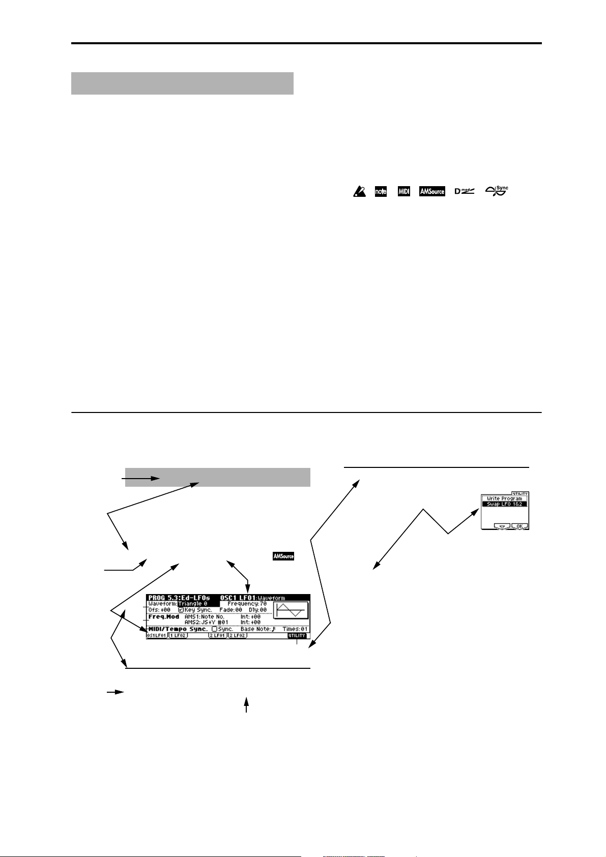
5.3–1: OS1LFO1 (OSC1 LFO1)
Indicates settings for the “OSC1 LFO1,” which is the first
LFO that can be used for oscillator 1.
5.3–1a
5.3–1b
5.3–1c
5.3–1a: OSC1 LFO1
Waveform [Triangle 0…Random6 (Vect.)]
PROG 5.3: Ed–LFOs
Page name
Range of possible
parameter values
Utility menu
command No.
5.3–1d
■ 5.3–1d: UTILITY
Utilty menu
command name
☞“Write Program” (1.1–1c)
For details on how to select the desired utility function,
refer to “PROG 1.1–1c: UTILITY.”
Swap LFO 1&2
This exchanges the settings of LFO 1 and 2. If LFO2 is
selected in AMS1 (Freq. AMS1) or AMS2 (Freq. AMS2) of
LFO1 Freq.Mod (5.3–1b), the settings will be invalid for
LFO2 after LFO1 and 2 have been exchanged. If you select
this from the OSC1 LFO1 or OSC1 LFO2 page, LFO1 and
LFO2 of OSC1 will be exchanged.
1 Select “Swap LFO 1&2” to access the dialog box.
2 To execute, press the [F8] (“OK”) key. To cancel without
executing, press the [F7] (“Cancel”) key.
iii
Page 4

Table of Contents
1. Program mode . . . . . . . . . . . . . . . . . . . . . . . 1
PROG PAGE MENU. . . . . . . . . . . . . . . . . . . . . . . . . . . . 1
PROG 1.1: Play . . . . . . . . . . . . . . . . . . . . . . . . . . . . . . .2
1.1–1: Program . . . . . . . . . . . . . . . . . . . . . . . . . . . . . . . . . . .2
1.1–2: P.Edit (Performance Editor) . . . . . . . . . . . . . . . . . . . .3
1.1–3: KARMA . . . . . . . . . . . . . . . . . . . . . . . . . . . . . . . . . . .5
1.1–4: K.RTC (KARMA RTC) . . . . . . . . . . . . . . . . . . . . . . . .6
1.1–5: Note (Note Activity) . . . . . . . . . . . . . . . . . . . . . . . . . .6
PROG 2.1: Ed–Basic . . . . . . . . . . . . . . . . . . . . . . . . . . .7
2.1–1: Basic (Prog Basic) . . . . . . . . . . . . . . . . . . . . . . . . . . . 7
2.1–2: OSC1 . . . . . . . . . . . . . . . . . . . . . . . . . . . . . . . . . . . . .8
2.1–3: OSC2 . . . . . . . . . . . . . . . . . . . . . . . . . . . . . . . . . . . .10
2.1–4: V.Zone (Velocity Zone) . . . . . . . . . . . . . . . . . . . . . .10
PROG 2.2: Ed–Ctrl. . . . . . . . . . . . . . . . . . . . . . . . . . . .10
2.2–1: Ctrls (Controls) . . . . . . . . . . . . . . . . . . . . . . . . . . . . .10
PROG 2.3: Ed–OSC . . . . . . . . . . . . . . . . . . . . . . . . . . .11
PROG 3.1: Ed–Pitch . . . . . . . . . . . . . . . . . . . . . . . . . .11
3.1–1: OSC1 . . . . . . . . . . . . . . . . . . . . . . . . . . . . . . . . . . . .11
3.1–2: OS1lfo (OSC1 LFO) . . . . . . . . . . . . . . . . . . . . . . . . .12
3.1–3: OSC2 . . . . . . . . . . . . . . . . . . . . . . . . . . . . . . . . . . . .13
3.1–4: OS2lfo (OSC2 LFO) . . . . . . . . . . . . . . . . . . . . . . . . .13
3.1–5: EG (Pitch EG) . . . . . . . . . . . . . . . . . . . . . . .13
PROG 4.1: Ed–Filter1 . . . . . . . . . . . . . . . . . . . . . . . . .15
4.1–1: Basic . . . . . . . . . . . . . . . . . . . . . . . . . . . . . . . . . . . .15
4.1–2: Mod.1 (Filter1 Modulation1) . . . . . . . . . . . . . . . . . . .16
4.1–3: Mod.2 (Filter1 Modulation2) . . . . . . . . . . . . . . . . . . .17
4.1–4: lfoMod (LFO Modulation) . . . . . . . . . . . . . . . . . . . . .17
4.1–5: EG (Filter1 EG) . . . . . . . . . . . . . . . . . . . . . .18
PROG 4.2: Ed–Filter2 . . . . . . . . . . . . . . . . . . . . . . . . .20
4.2–1: Basic . . . . . . . . . . . . . . . . . . . . . . . . . . . . . . . . . . . .20
4.2–2: Mod.1 (Filter2 Modulation1) . . . . . . . . . . . . . . . . . . .20
4.2–3: Mod.2 (Filter2 Modulation2) . . . . . . . . . . . . . . . . . . .20
4.2–4: lfoMod (LFO Modulation) . . . . . . . . . . . . . . . . . . . . .20
4.2–5: EG (Filter2 EG) . . . . . . . . . . . . . . . . . . . . . .20
PROG 5.1: Ed–Amp1. . . . . . . . . . . . . . . . . . . . . . . . . . 20
5.1–1: Lvl/Pan (Level/Pan) . . . . . . . . . . . . . . . . . . . . . . . . .20
5.1–2: Mod. (Amp1 Modulation) . . . . . . . . . . . . . . . . . . . . .20
5.1–3: EG (Amp1 EG) . . . . . . . . . . . . . . . . . . . . . .22
PROG 5.1: Ed–Amp. . . . . . . . . . . . . . . . . . . . . . . . . . . 23
PROG 5.2: Ed–Amp2 . . . . . . . . . . . . . . . . . . . . . . . . . 23
5.2–1: Lvl/Pan (Level/Pan) . . . . . . . . . . . . . . . . . . . . . . . . 23
5.2–2: Mod. (Amp2 Modulation) . . . . . . . . . . . . . . . . . . . . 23
5.2–3: EG (Amp2 EG) . . . . . . . . . . . . . . . . . . . . . . 23
PROG 5.2: Ed–EGs. . . . . . . . . . . . . . . . . . . . . . . . . . . 23
PROG 5.3: Ed–LFOs. . . . . . . . . . . . . . . . . . . . . . . . . . 24
5.3–1: OS1LFO1 (OSC1 LFO1) . . . . . . . . . . . . . . 24
5.3–2: 1LFO2 (OSC1 LFO2) . . . . . . . . . . . . . . . . . . . . . . . 25
5.3–3: 2LFO1 (OSC2 LFO1) . . . . . . . . . . . . . . . . . . . . . . . 25
5.3–4: 2LFO2 (OSC2 LFO2) . . . . . . . . . . . . . . . . . . . . . . . 25
PROG 6.1: Ed–KARMA . . . . . . . . . . . . . . . . . . . . . . . 26
6.1–1: Setup . . . . . . . . . . . . . . . . . . . . . . . . . . . . . . . . . . . 26
6.1–2: Key Z/T (KeyZ/Thru) . . . . . . . . . . . . . . . . . . . . . . . . 27
6.1–3: RxFltr (Receive Filter). . . . . . . . . . . . . . . . . . . . . . . 28
6.1–4: TxFltr (Transmit Filter) . . . . . . . . . . . . . . . . . . . . . . 28
PROG 6.2: Ed-KARMA Mdl . . . . . . . . . . . . . . . . . . . . 29
6.2–1: Parm1 (Parameter 1) . . . . . . . . . . . . . . . . . . . . . . . 29
6.2–2: Parm2 (Parameter 2) . . . . . . . . . . . . . . . . . . . . . . . 31
PROG 6.3: Ed-KARMA GE . . . . . . . . . . . . . . . . . . . . . 32
6.3–1: GE P...4 (GE Parameter 1...4) . . . . . . . . . . . . . . . . 32
6.3–1: GE P...8 (GE Parameter 5...8) . . . . . . . . . . . . . . . . 32
6.3–1: GE P...12 (GE Parameter 9...12) . . . . . . . . . . . . . . 32
6.3–1: GE P...16 (GE Parameter 13...16) . . . . . . . . . . . . . 32
PROG 6.4: Ed-KARMA RT . . . . . . . . . . . . . . . . . . . . . 34
6.4–1: RTP ..4 (RT Parameter 1...4) . . . . . . . . . . . . . . . . . 34
6.4–2: RTP ..8 (RT Parameter 5...8) . . . . . . . . . . . . . . . . . 34
6.4–3: DynMIDI (Dynamic MIDI) . . . . . . . . . . . . . . . . . . . . 36
6.4–4: Name1 . . . . . . . . . . . . . . . . . . . . . . . . . . . . . . . . . . 36
6.4–5: Name2 . . . . . . . . . . . . . . . . . . . . . . . . . . . . . . . . . . 36
PROG 7.1: Ed–BUS . . . . . . . . . . . . . . . . . . . . . . . . . . 37
7.1–1: BUS . . . . . . . . . . . . . . . . . . . . . . . . . . . . . . . . . . . . 37
7.1–2: Route (Routing) . . . . . . . . . . . . . . . . . . . . . . . . . . . 38
PROG 7.2: Ed–InsertFX . . . . . . . . . . . . . . . . . . . . . . . 38
7.2–1: Setup . . . . . . . . . . . . . . . . . . . . . . . . . . . . . . . . . . . 38
7.2–2: IFX 1 (Insert Effect1). . . . . . . . . . . . . . . . . . . . . . . . 39
7.2–3: IFX 2 (Insert Effect2). . . . . . . . . . . . . . . . . . . . . . . . 39
7.2–4: IFX 3 (Insert Effect3). . . . . . . . . . . . . . . . . . . . . . . . 39
7.2–5: IFX 4 (Insert Effect4). . . . . . . . . . . . . . . . . . . . . . . . 39
7.2–6: IFX 5 (Insert Effect5). . . . . . . . . . . . . . . . . . . . . . . . 39
7.2–7: Routing (Routing) . . . . . . . . . . . . . . . . . . . . . . . . . . 40
PROG 7.3: Ed–MasterFX . . . . . . . . . . . . . . . . . . . . . . 40
7.3–1: Setup . . . . . . . . . . . . . . . . . . . . . . . . . . . . . . . . . . . 40
7.3–2: MFX 1 (Master Effect1). . . . . . . . . . . . . . . . . . . . . . 41
7.3–3: MFX 2 (Master Effect2). . . . . . . . . . . . . . . . . . . . . . 41
7.3–4: MEQ (Master EQ) . . . . . . . . . . . . . . . . . . . . . . . . . . 41
iv
Page 5

2. Combination mode . . . . . . . . . . . . . . . . . . . 43
COMBI PAGE MENU . . . . . . . . . . . . . . . . . . . . . . . . . 43
COMBI 1.1: Play. . . . . . . . . . . . . . . . . . . . . . . . . . . . . 43
1.1–1: Combi (Combination) . . . . . . . . . . . . . . . . . . . . . . . . 43
1.1–2: Prog (Timbre Program) . . . . . . . . . . . . . . . . . . . . . . 45
1.1–3: Mix (Mixer) . . . . . . . . . . . . . . . . . . . . . . . . . . . . . . . .46
1.1-4: KARMA . . . . . . . . . . . . . . . . . . . . . . . . . . . . . . . . . . . 47
1.1–5: K.RTC (KARMA RTC) . . . . . . . . . . . . . . . . . . . . . . . 48
1.1–6: Note (Note Activity) . . . . . . . . . . . . . . . . . . . . . . . . . 48
COMBI 2.1: Ed–Prog/Mixer . . . . . . . . . . . . . . . . . . . . 48
2.1–1: Prog (Timbre Program) . . . . . . . . . . . . . . . . . . . . . . 48
2.1–2: Mix (Mixer) . . . . . . . . . . . . . . . . . . . . . . . . . . . . . . . .48
COMBI 2.2: Ed–Ctrl . . . . . . . . . . . . . . . . . . . . . . . . . . 49
2.2–1: Ctrls (Controls). . . . . . . . . . . . . . . . . . . . . . . . . . . . .49
COMBI 2.3: Ed–MOSS . . . . . . . . . . . . . . . . . . . . . . . . 49
COMBI 3.1: Ed–Param1. . . . . . . . . . . . . . . . . . . . . . . 49
3.1–1: MIDI . . . . . . . . . . . . . . . . . . . . . . . . . . . . . . . . . . . . . 49
3.1–2: OSC . . . . . . . . . . . . . . . . . . . . . . . . . . . . . . . . . . . . .50
3.1–3: Pitch . . . . . . . . . . . . . . . . . . . . . . . . . . . . . . . . . . . . . 50
COMBI 3.2: Ed–Param2. . . . . . . . . . . . . . . . . . . . . . . 51
3.2–1: KARMA . . . . . . . . . . . . . . . . . . . . . . . . . . . . . . . . . .51
3.2–2: Other . . . . . . . . . . . . . . . . . . . . . . . . . . . . . . . . . . . . 52
COMBI 3.3: Ed–Key Zone . . . . . . . . . . . . . . . . . . . . . 52
3.3–1: Key (Key Zone) . . . . . . . . . . . . . . . . . . . . . . . . . . . . 52
3.3–2: Slope (Key Slope) . . . . . . . . . . . . . . . . . . . . . . . . . . 53
3.3–3: Review . . . . . . . . . . . . . . . . . . . . . . . . . . . . . . . . . . .53
COMBI 3.4: Ed–Vel Zone (Velocity Zone) . . . . . . . . 53
3.4–1: Vel (Velocity Zone). . . . . . . . . . . . . . . . . . . . . . . . . . 53
3.4–2: Slope (Velocity Slope) . . . . . . . . . . . . . . . . . . . . . . . 54
3.4–3: Review . . . . . . . . . . . . . . . . . . . . . . . . . . . . . . . . . . .54
COMBI 4.1: Ed–MIDI Filter1 . . . . . . . . . . . . . . . . . . . 54
4.1–1: MIDI 1–1 (MIDI Filter 1–1) . . . . . . . . . . . . . . . . . . . . 54
4.1–2: MIDI 1–2 (MIDI Filter 1–2) . . . . . . . . . . . . . . . . . . . . 55
COMBI 4.2: Ed–MIDI Filter2 . . . . . . . . . . . . . . . . . . . 55
4.2–1: MIDI 2–1 (MIDI Filter 2–1) . . . . . . . . . . . . . . . . . . . . 55
4.2–2: MIDI 2–2 (MIDI Filter 2–2) . . . . . . . . . . . . . . . . . . . . 55
COMBI 4.3: Ed–MIDI Filter3 . . . . . . . . . . . . . . . . . . . 55
4.3–1: MIDI 3–1 (MIDI Filter 3–1) . . . . . . . . . . . . . . . . . . . . 55
4.3–2: MIDI 3–2 (MIDI Filter 3–2) . . . . . . . . . . . . . . . . . . . . 55
COMBI 6.1: Ed–KARMA . . . . . . . . . . . . . . . . . . . . . . . 57
6.1–1: Setup . . . . . . . . . . . . . . . . . . . . . . . . . . . . . . . . . . . 57
6.1–2: MIDI I/O . . . . . . . . . . . . . . . . . . . . . . . . . . . . . . . . . 58
6.1–3: Key Z (KeyZone) . . . . . . . . . . . . . . . . . . . . . . . . . . 59
6.1–4: Key T (Key Thru) . . . . . . . . . . . . . . . . . . . . . . . . . . 60
6.1–5: RxFltr (Receive Filter). . . . . . . . . . . . . . . . . . . . . . . 60
6.1–6: TxFltr (Transmit Filter) . . . . . . . . . . . . . . . . . . . . . . 60
COMBI: 6.2 Ed-KARMA Mdl. . . . . . . . . . . . . . . . . . . . 61
6.2–1: Parm1 (Parameter 1) . . . . . . . . . . . . . . . . . . . . . . . 61
6.2–2: Parm2 (Parameter 2) . . . . . . . . . . . . . . . . . . . . . . . 61
COMBI 6.3: Ed-KARMA GE . . . . . . . . . . . . . . . . . . . . 62
6.3–1: GE P..4 (GE Parameter 1...4). . . . . . . . . . . . . . . . . 62
6.3–2: GE P..8 (GE Parameter 5...8). . . . . . . . . . . . . . . . . 62
6.3–3: GE P..12 (GE Parameter 9...2). . . . . . . . . . . . . . . . 62
6.3–4: GE P..16 (GE Parameter 13...16). . . . . . . . . . . . . . 62
COMBI 6.4: Ed-KARMA RT . . . . . . . . . . . . . . . . . . . . 63
6.4–1: RTP ..4 (RT Parameter 1...4) . . . . . . . . . . . . . . . . . 63
6.4–2: RTP ..8 (RT Parameter 5...8) . . . . . . . . . . . . . . . . . 63
6.4–3: DynMIDI (Dynamic MIDI) . . . . . . . . . . . . . . . . . . . . 63
6.4–4: Name1 . . . . . . . . . . . . . . . . . . . . . . . . . . . . . . . . . . 64
6.4–5: Name2 . . . . . . . . . . . . . . . . . . . . . . . . . . . . . . . . . . 64
6.4–6: Rndm1 (Random 1) . . . . . . . . . . . . . . . . . . . . . . . . 64
6.4–7: Rndm2 (Random 2) . . . . . . . . . . . . . . . . . . . . . . . . 64
COMBI 7.1: Ed–BUS . . . . . . . . . . . . . . . . . . . . . . . . . . 65
7.1–1: BUS (BUS T01...08) . . . . . . . . . . . . . . . . . . . . . . . . 65
7.1–2: Route (Routing) . . . . . . . . . . . . . . . . . . . . . . . . . . . 66
COMBI 7.2: Ed-InsertFX . . . . . . . . . . . . . . . . . . . . . . . 66
7.2–1: Setup . . . . . . . . . . . . . . . . . . . . . . . . . . . . . . . . . . . 66
7.2–2: IFX 1 (Insert Effect1) . . . . . . . . . . . . . . . . . . . . . . . 67
7.2–3: IFX 2 (Insert Effect2) . . . . . . . . . . . . . . . . . . . . . . . 67
7.2–4: IFX 3 (Insert Effect3) . . . . . . . . . . . . . . . . . . . . . . . 67
7.2–5: IFX 4 (Insert Effect4) . . . . . . . . . . . . . . . . . . . . . . . 67
7.2–6: IFX 5 (Insert Effect5) . . . . . . . . . . . . . . . . . . . . . . . 67
7.2–7: Route (Routing) . . . . . . . . . . . . . . . . . . . . . . . . . . . 67
COMBI 7.3: Ed–MasterFX . . . . . . . . . . . . . . . . . . . . . 67
7.3–1: Setup . . . . . . . . . . . . . . . . . . . . . . . . . . . . . . . . . . . 67
7.3–2: MFX1 (Master Effect1) . . . . . . . . . . . . . . . . . . . . . . 68
7.3–3: MFX2 (Master Effect2) . . . . . . . . . . . . . . . . . . . . . . 68
7.3–4: MEQ (Master EQ). . . . . . . . . . . . . . . . . . . . . . . . . . 68
COMBI 4.4: Ed–MIDI Filter4 . . . . . . . . . . . . . . . . . . . 56
4.4–1: MIDI 4–1 (MIDI Filter 4–1) . . . . . . . . . . . . . . . . . . . . 56
4.4–2: MIDI 4–2 (MIDI Filter 4–2) . . . . . . . . . . . . . . . . . . . . 56
v
Page 6

3. Sequencer mode. . . . . . . . . . . . . . . . . . . . . 69
SEQ PAGE MENU . . . . . . . . . . . . . . . . . . . . . . . . . . . . 69
SEQ 1.1: Play/REC . . . . . . . . . . . . . . . . . . . . . . . . . . .69
1.1–1: Play.REC (Play/REC). . . . . . . . . . . . . . . . . . . . . . . . 69
1.1–2: Prog...8 (Program T01...08) . . . . . . . . . . . . . . . . . . .74
1.1–3: Prog...16 (Program T09...16) . . . . . . . . . . . . . . . . . .74
1.1–4: Mix..8 (Mixer T01...08) . . . . . . . . . . . . . . . . . . . . . . .75
1.1–5: Mix..16 (Mixer T09...16) . . . . . . . . . . . . . . . . . . . . . .75
1.1–6: Pref. (Preference). . . . . . . . . . . . . . . . . . . . . . . . . . . 75
1.1–7: K.RTC (KARMA RTC) . . . . . . . . . . . . . . . . . . . . . . .77
SEQ 1.2: Loop . . . . . . . . . . . . . . . . . . . . . . . . . . . . . . .77
1.2–1: Loop...8 (Track Play Loop T01...08). . . . . . . . . . . . . 77
1.2–2: Loop...16 (Track Play Loop T09...16). . . . . . . . . . . . 77
SEQ 2.1: Cue List . . . . . . . . . . . . . . . . . . . . . . . . . . . .78
2.1–1: Cue List . . . . . . . . . . . . . . . . . . . . . . . . . . . . . . . . . .78
SEQ 2.2: Controller . . . . . . . . . . . . . . . . . . . . . . . . . . .81
2.2–1: Ctrls (Controls) . . . . . . . . . . . . . . . . . . . . . . . . . . . . .81
SEQ2.3: MOSS. . . . . . . . . . . . . . . . . . . . . . . . . . . . . . . 82
SEQ 3.1: Param1 . . . . . . . . . . . . . . . . . . . . . . . . . . . . .82
3.1–1: MIDI...8 (MIDI T01...08) . . . . . . . . . . . . . . . . . . . . . .82
3.1–2: MIDI...16 (MIDI T09...16) . . . . . . . . . . . . . . . . . . . . .82
3.1–3: OSC..8 (OSC T01...08) . . . . . . . . . . . . . . . . . . . . . .83
3.1–4: OSC..16 (OSC T09...16) . . . . . . . . . . . . . . . . . . . . .83
3.1–5: Ptch..8 (Pitch T01...08) . . . . . . . . . . . . . . . . . . . . . .83
3.1–6: Ptch..16 (Pitch T09...16) . . . . . . . . . . . . . . . . . . . . .83
SEQ 3.2: Param2 . . . . . . . . . . . . . . . . . . . . . . . . . . . . .84
3.2–1: KRM..8 (KARMA T01...08). . . . . . . . . . . . . . . . . . . .84
3.2–2: KRM..16 (KARMA T09...16). . . . . . . . . . . . . . . . . . .84
3.2–3: Othr..8 (Other T01...08) . . . . . . . . . . . . . . . . . . . . . . 85
3.2–4: Othr..16 (Other T09...16) . . . . . . . . . . . . . . . . . . . . . 85
SEQ 3.3: Key Zone . . . . . . . . . . . . . . . . . . . . . . . . . . .85
3.3–1: Key..8 (Key T01...08) . . . . . . . . . . . . . . . . . . . . . . . .85
3.3–2: Key..16 (Key T09...16) . . . . . . . . . . . . . . . . . . . . . . .85
3.3–3: Slp..8 (Slope T01...08) . . . . . . . . . . . . . . . . . . . . . . .86
3.3–4: Slp..16 (Slope T09...16) . . . . . . . . . . . . . . . . . . . . . .86
3.3–5: Review . . . . . . . . . . . . . . . . . . . . . . . . . . . . . . . . . . .86
SEQ 3.4: Vel Zone . . . . . . . . . . . . . . . . . . . . . . . . . . . .86
3.4–1: Vel..8 (Vel T01...08) . . . . . . . . . . . . . . . . . . . . . . . . .86
3.4–2: Vel..16 (Vel T09...16) . . . . . . . . . . . . . . . . . . . . . . . .86
3.4–3: Slp..8 (Slope T01...08) . . . . . . . . . . . . . . . . . . . . . . .87
3.4–4: Slp..16 (Slope T09...16) . . . . . . . . . . . . . . . . . . . . . .87
3.4–5: Review . . . . . . . . . . . . . . . . . . . . . . . . . . . . . . . . . . .87
SEQ 4.1: MIDI Filter1 . . . . . . . . . . . . . . . . . . . . . . . . . 87
4.1–1: M1–1..8 (MIDI Filter1–1 T01...08). . . . . . . . . . . . . . 87
4.1–2: 1–1..16 (MIDI Filter1–1 T09...16) . . . . . . . . . . . . . . 87
4.1–3: 1–2..8 (MIDI Filter1–2 T01...08) . . . . . . . . . . . . . . . 88
4.1–4: 1–2..16 (MIDI Filter1–2 T09...16) . . . . . . . . . . . . . . 88
SEQ 4.2: MIDI Filter2 . . . . . . . . . . . . . . . . . . . . . . . . . 88
4.2–1: M2–1..8 (MIDI Filter2–1 T01...08). . . . . . . . . . . . . . 88
4.2–2: 2–1..16 (MIDI Filter2–1 T09...16) . . . . . . . . . . . . . . 88
4.2–3: 2–2..8 (MIDI Filter2–2 T01...08) . . . . . . . . . . . . . . . 88
4.2–4: 2–2..16 (MIDI Filter2–2 T09...16) . . . . . . . . . . . . . . 88
SEQ 4.3: MIDI Filter3 . . . . . . . . . . . . . . . . . . . . . . . . . 89
4.3–1: M3–1..8 (MIDI Filter3–1 T01...08). . . . . . . . . . . . . . 89
4.3–2: 3–1..16 (MIDI Filter3–1 T09...16) . . . . . . . . . . . . . . 89
4.3–3: 3–2..8 (MIDI Filter3–2 T01...08) . . . . . . . . . . . . . . . 89
4.3–4: 3–2..16 (MIDI Filter3–2 T09...16) . . . . . . . . . . . . . . 89
SEQ 4.4: MIDI Filter4 . . . . . . . . . . . . . . . . . . . . . . . . . 89
4.4–1: M4–1..8 (MIDI Filter4–1 T01...08). . . . . . . . . . . . . . 89
4.4–2: 4–2..16 (MIDI Filter4–1 T09...16) . . . . . . . . . . . . . . 89
4.4–3: 4–2..8 (MIDI Filter4–2 T01...08) . . . . . . . . . . . . . . . 90
4.4–4: 4–2..16 (MIDI Filter4–2 T09...16) . . . . . . . . . . . . . . 90
SEQ 5.1: RPPR . . . . . . . . . . . . . . . . . . . . . . . . . . . . . . 90
5.1–1: Pattern . . . . . . . . . . . . . . . . . . . . . . . . . . . . . . . . . . 90
5.1–2: RPPR Setup . . . . . . . . . . . . . . . . . . . . . . . . . . . . . . 93
SEQ 5.2: Track Edit . . . . . . . . . . . . . . . . . . . . . . . . . . 95
5.2–1: Track Edit . . . . . . . . . . . . . . . . . . . . . . . . . . . . . . . . 95
SEQ 6.1: KARMA . . . . . . . . . . . . . . . . . . . . . . . . . . . 103
6.1–1: Setup . . . . . . . . . . . . . . . . . . . . . . . . . . . . . . . . . . 103
6.1–2: MIDI I/O . . . . . . . . . . . . . . . . . . . . . . . . . . . . . . . . 104
6.1–3: KeyZ (Key Zone). . . . . . . . . . . . . . . . . . . . . . . . . . 106
6.1–4: Key T (KeyThru) . . . . . . . . . . . . . . . . . . . . . . . . . . 106
6.1–5: RxFiltr (Receive Filter) . . . . . . . . . . . . . . . . . . . . . 107
6.1–6: TxFiltr (Transmit Filter) . . . . . . . . . . . . . . . . . . . . . 107
6.1–7: Note (Note Activity). . . . . . . . . . . . . . . . . . . . . . . . 107
SEQ 6.2: KARMA Mdl. . . . . . . . . . . . . . . . . . . . . . . . 108
6.2–1: Parm1 (Parameter 1) . . . . . . . . . . . . . . . . . . . . . . 108
6.2–2: Parm2 (Parameter 2) . . . . . . . . . . . . . . . . . . . . . . 108
SEQ 6.3: KARMA GE . . . . . . . . . . . . . . . . . . . . . . . . 109
6.3–1: GE P..4 (GE Parameter 1...4). . . . . . . . . . . . . . . . 109
6.3–2: GE P..8 (GE Parameter 5...8). . . . . . . . . . . . . . . . 109
6.3–3: GE P..12 (GE Parameter 9...12). . . . . . . . . . . . . . 109
6.3–4: GE P..16 (GE Parameter 13...16). . . . . . . . . . . . . 109
vi
Page 7

SEQ 6.4: KARMA RT . . . . . . . . . . . . . . . . . . . . . . . . 110
6.4–1: RTP..4 (RT Parameter 1...4) . . . . . . . . . . . . . . . . .110
6.4–2: RTP..8 (RT Parameter 5...8) . . . . . . . . . . . . . . . . .110
6.4–3: DynMIDI (Dynamic MIDI) . . . . . . . . . . . . . . . . . . . . 110
6.4–4: Name1 . . . . . . . . . . . . . . . . . . . . . . . . . . . . . . . . . . 110
6.4–5: Name2 . . . . . . . . . . . . . . . . . . . . . . . . . . . . . . . . . . 110
6.4–6: Rndm1 (Random 1) . . . . . . . . . . . . . . . . . . . . . . . . 111
6.4–7: Rndm2 (Random 2) . . . . . . . . . . . . . . . . . . . . . . . . 111
SEQ 7.1: BUS . . . . . . . . . . . . . . . . . . . . . . . . . . . . . . 111
7.1–1: BUS..8 (BUS T01...08). . . . . . . . . . . . . . . . . . . . . . 111
7.1–2: BUS..16 (BUS T09...16). . . . . . . . . . . . . . . . . . . . . 111
7.1–3: Route (Routing) . . . . . . . . . . . . . . . . . . . . . . . . . . . 112
SEQ 7.2: Insert FX . . . . . . . . . . . . . . . . . . . . . . . . . . 112
7.2–1: Setup . . . . . . . . . . . . . . . . . . . . . . . . . . . . . . . . . . . 112
7.2–2: IFX1 (Insert Effect1). . . . . . . . . . . . . . . . . . . . . . . .113
7.2–3: IFX2 (Insert Effect2). . . . . . . . . . . . . . . . . . . . . . . .113
7.2–4: IFX3 (Insert Effect3). . . . . . . . . . . . . . . . . . . . . . . .113
7.2–5: IFX4 (Insert Effect4). . . . . . . . . . . . . . . . . . . . . . . .113
7.2–6: IFX5 (Insert Effect5). . . . . . . . . . . . . . . . . . . . . . . .113
7.2–7: Route (Routing) . . . . . . . . . . . . . . . . . . . . . . . . . . . 113
SEQ 7.3: Master FX . . . . . . . . . . . . . . . . . . . . . . . . . 113
7.3–1: Setup . . . . . . . . . . . . . . . . . . . . . . . . . . . . . . . . . . . 113
7.3–2: MFX1 (Master Effect1). . . . . . . . . . . . . . . . . . . . . .114
7.3–3: MFX2 (Master Effect2). . . . . . . . . . . . . . . . . . . . . .114
7.3–4: Master EQ (Master EQ) . . . . . . . . . . . . . . . . . . . . .114
4. Song Play mode. . . . . . . . . . . . . . . . . . . . . 115
S.PLAY PAGE MENU. . . . . . . . . . . . . . . . . . . . . . . . 115
S.PLAY 1.1: Play . . . . . . . . . . . . . . . . . . . . . . . . . . . 115
1.1–1: Play . . . . . . . . . . . . . . . . . . . . . . . . . . . . . . . . . . . . 115
1.1–2: Prog..8 (Program T01...08) . . . . . . . . . . . . . . . . . . 117
1.1–3: Prog..16 (Program T09...16) . . . . . . . . . . . . . . . . . 117
1.1–4: Mix..8 (Mixer T01...08) . . . . . . . . . . . . . . . . . . . . . . 117
1.1–5: Mix..16 (Mixer T09...16) . . . . . . . . . . . . . . . . . . . . . 117
1.1–6: Preference . . . . . . . . . . . . . . . . . . . . . . . . . . . . . . . 118
1.1–7: K.RTC (KARMA RTC) . . . . . . . . . . . . . . . . . . . . . . 118
S.PLAY 2.2: Controller . . . . . . . . . . . . . . . . . . . . . . 119
2.2–1: Ctrls (Controls). . . . . . . . . . . . . . . . . . . . . . . . . . . .119
S.PLAY 2.3: MOSS. . . . . . . . . . . . . . . . . . . . . . . . . . 119
2.3–1: MOS..8 (MOSS T01...08). . . . . . . . . . . . . . . . . . . . 119
2.3–2: MOS..16 (MOSS T09...16). . . . . . . . . . . . . . . . . . . 119
S.PLAY 3.1: Param . . . . . . . . . . . . . . . . . . . . . . . . . 120
3.1–1: Param..8 (Status/Scale T01...08). . . . . . . . . . . . . . 120
3.1–2: Prm..16 (Status/Scale T09...16). . . . . . . . . . . . . . . 120
3.1–3: KRM..8 (KARMA T01...08). . . . . . . . . . . . . . . . . . . 120
3.1–4: KRM..16 (KARMA T09...16). . . . . . . . . . . . . . . . . . 120
S.PLAY 4.1: Select Directory. . . . . . . . . . . . . . . . . . 121
4.1–1: Select Directory . . . . . . . . . . . . . . . . . . . . . . . . . . 121
S.PLAY 4.2: Jukebox . . . . . . . . . . . . . . . . . . . . . . . . 121
4.2–1: Jukebox . . . . . . . . . . . . . . . . . . . . . . . . . . . . . . . . 121
S.PLAY 6.1: KARMA. . . . . . . . . . . . . . . . . . . . . . . . . 122
6.1-1: Setup . . . . . . . . . . . . . . . . . . . . . . . . . . . . . . . . . . . 122
6.1–2: MIDI I/O . . . . . . . . . . . . . . . . . . . . . . . . . . . . . . . . 123
6.1–3: Key Z (KeyZone) . . . . . . . . . . . . . . . . . . . . . . . . . 124
6.1–4: Key T (Key Thru) . . . . . . . . . . . . . . . . . . . . . . . . . 125
6.1–5: RxFiltr (Receive Filter) . . . . . . . . . . . . . . . . . . . . . 125
6.1–6: TxFiltr (Transmit Filter) . . . . . . . . . . . . . . . . . . . . . 125
6.1–7: Note Activity . . . . . . . . . . . . . . . . . . . . . . . . . . . . . 125
S.PLAY 6.2: KARMA Mdl . . . . . . . . . . . . . . . . . . . . . 126
6.2–1: Parm1 (Parameter 1) . . . . . . . . . . . . . . . . . . . . . . 126
6.2–2: Parm2 (Parameter 2) . . . . . . . . . . . . . . . . . . . . . . 126
S.PLAY 6.3: KARMA GE. . . . . . . . . . . . . . . . . . . . . . 127
6.3–1: GE P..4 (GE Parameter 1...4). . . . . . . . . . . . . . . . 127
6.3–2: GE P..8 (GE Parameter 5...8). . . . . . . . . . . . . . . . 127
6.3–3: GE P..12 (GE Parameter 9...12). . . . . . . . . . . . . . 127
6.3–4: GE P..16 (GE Parameter 13...16). . . . . . . . . . . . . 127
S.PLAY 6.4: KARMA RT . . . . . . . . . . . . . . . . . . . . . . 128
6.4–1: RTP..4 (RT Parameter 1...4) . . . . . . . . . . . . . . . . 128
6.4–2: RTP..8 (RT Parameter 5...8) . . . . . . . . . . . . . . . . 128
6.4–3: DynMIDI (Dynamic MIDI) . . . . . . . . . . . . . . . . . . . 128
6.4–4: Name1 . . . . . . . . . . . . . . . . . . . . . . . . . . . . . . . . . 128
6.4–5: Name2 . . . . . . . . . . . . . . . . . . . . . . . . . . . . . . . . . 128
6.4–6: Rndm1 (Random 1) . . . . . . . . . . . . . . . . . . . . . . . 129
6.4–7: Rndm2 (Random 2) . . . . . . . . . . . . . . . . . . . . . . . 129
S.PLAY 7.1: BUS. . . . . . . . . . . . . . . . . . . . . . . . . . . . 129
7.1–1: BUS..8 (BUS T01...08) . . . . . . . . . . . . . . . . . . . . . 129
7.1–2: BUS..16 (BUS T09...16) . . . . . . . . . . . . . . . . . . . . 129
7.1–3: Route (Routing) . . . . . . . . . . . . . . . . . . . . . . . . . . 130
S.PLAY 7.2: Insert FX. . . . . . . . . . . . . . . . . . . . . . . . 130
7.2–1: Setup . . . . . . . . . . . . . . . . . . . . . . . . . . . . . . . . . . 130
7.2–2: IFX1 (Insert Effect1) . . . . . . . . . . . . . . . . . . . . . . . 131
7.2–3: IFX2 (Insert Effect2) . . . . . . . . . . . . . . . . . . . . . . . 131
7.2–4: IFX3 (Insert Effect3) . . . . . . . . . . . . . . . . . . . . . . . 131
7.2–5: IFX4 (Insert Effect4) . . . . . . . . . . . . . . . . . . . . . . . 131
7.2–6: IFX5 (Insert Effect5) . . . . . . . . . . . . . . . . . . . . . . . 131
7.2–7: Route (Routing) . . . . . . . . . . . . . . . . . . . . . . . . . . 131
S.PLAY 7.3: Master FX . . . . . . . . . . . . . . . . . . . . . . . 131
7.3–1: Setup . . . . . . . . . . . . . . . . . . . . . . . . . . . . . . . . . . 131
7.3–2: MFX1 (Master Effect1) . . . . . . . . . . . . . . . . . . . . . 132
7.3–3: MFX2 (Master Effect2) . . . . . . . . . . . . . . . . . . . . . 132
7.3–4: MEQ (Master EQ). . . . . . . . . . . . . . . . . . . . . . . . . 132
vii
Page 8

5. Global mode . . . . . . . . . . . . . . . . . . . . . . . 133
GLOBAL PAGE MENU . . . . . . . . . . . . . . . . . . . . . . .133
GLOBAL 1.1: System . . . . . . . . . . . . . . . . . . . . . . . .133
1.1–1: Basic . . . . . . . . . . . . . . . . . . . . . . . . . . . . . . . . . . .133
1.1–2: Pref. (System Preference) . . . . . . . . . . . . . . . . . . . 136
GLOBAL 2.1: MIDI . . . . . . . . . . . . . . . . . . . . . . . . . . .137
2.1–1: MIDI . . . . . . . . . . . . . . . . . . . . . . . . . . . . . . . . . . . . 137
GLOBAL 3.1: User Scale . . . . . . . . . . . . . . . . . . . . .140
3.1–1: Octave . . . . . . . . . . . . . . . . . . . . . . . . . . . . . . . . . .140
3.1–2: All Notes. . . . . . . . . . . . . . . . . . . . . . . . . . . . . . . . .141
GLOBAL 4.1: Category Name . . . . . . . . . . . . . . . . .141
4.1–1: P.0..7 (Prog.00...07). . . . . . . . . . . . . . . . . . . . . . . .141
4.1–2: P.8..15 (Prog.08...15). . . . . . . . . . . . . . . . . . . . . . .141
4.1–3: C.0..7 (Comb.00...07). . . . . . . . . . . . . . . . . . . . . . . 141
4.1–4: C.8..15 (Comb.08...15). . . . . . . . . . . . . . . . . . . . . . 141
GLOBAL 5.1: DKit (Drum Kit). . . . . . . . . . . . . . . . . . 142
5.1–1: High (High Sample) . . . . . . . . . . . . . . . . . . . . . . . .142
5.1–2: Low (Low Sample) . . . . . . . . . . . . . . . . . . . . . . . . .144
5.1–3: Voice (Voice/Mixer) . . . . . . . . . . . . . . . . . . . . . . . .144
GLOBAL 6.1: Controller . . . . . . . . . . . . . . . . . . . . . .145
6.1–1: Foot . . . . . . . . . . . . . . . . . . . . . . . . . . . . . . . . . . . .145
6.1–2: KARMA1 . . . . . . . . . . . . . . . . . . . . . . . . . . . . . . . .146
6.1–3: KARMA2 . . . . . . . . . . . . . . . . . . . . . . . . . . . . . . . .146
6. Disk mode . . . . . . . . . . . . . . . . . . . . . . . . . 149
DISK PAGE MENU. . . . . . . . . . . . . . . . . . . . . . . . . . . 150
1.1–1: Load . . . . . . . . . . . . . . . . . . . . . . . . . . . . . . . .150
1.1–2: Save. . . . . . . . . . . . . . . . . . . . . . . . . . . . . . . . .153
1.1–3: Utility . . . . . . . . . . . . . . . . . . . . . . . . . . . . . . . .155
1.1–4: Media Information . . . . . . . . . . . . . . . . . . . . .157
7. Effect Guide . . . . . . . . . . . . . . . . . . . . . . . 159
Overview . . . . . . . . . . . . . . . . . . . . . . . . . . . . . . . . . .159
1. Effects in each mode. . . . . . . . . . . . . . . . . . . . . . . . . . . 159
2. Dynamic modulation (Dmod). . . . . . . . . . . . . . . . . . . . . 159
3. Effect I/O . . . . . . . . . . . . . . . . . . . . . . . . . . . . . . . . . . . .159
Insert Effects (IFX 1, 2, 3, 4, 5) . . . . . . . . . . . . . . . . .160
1. In/Out . . . . . . . . . . . . . . . . . . . . . . . . . . . . . . . . . . . . . .160
2. Routing . . . . . . . . . . . . . . . . . . . . . . . . . . . . . . . . . . . . .160
3. Mixer . . . . . . . . . . . . . . . . . . . . . . . . . . . . . . . . . . . . . . .162
4. Controlling the Insert Effects via MIDI. . . . . . . . . . . . . .163
Master Effects (MFX1, 2) . . . . . . . . . . . . . . . . . . . . . 163
1. In/Out . . . . . . . . . . . . . . . . . . . . . . . . . . . . . . . . . . . . . . 163
2. Routing . . . . . . . . . . . . . . . . . . . . . . . . . . . . . . . . . . . . 164
3. Mixer . . . . . . . . . . . . . . . . . . . . . . . . . . . . . . . . . . . . . . 165
4. Controlling the Master Effects via MIDI . . . . . . . . . . . . 166
Master EQ . . . . . . . . . . . . . . . . . . . . . . . . . . . . . . . . . 166
Individual Outputs . . . . . . . . . . . . . . . . . . . . . . . . . . 166
Filter/Dynamic . . . . . . . . . . . . . . . . . . . . . . . . . . . . . 168
000: No Effect . . . . . . . . . . . . . . . . . . . . . . . . . . . . . . . . . 168
001: St.Amp Sim (Stereo Amp Simulation) . . . . . . . . . . . 168
002: St.Compressor (Stereo Compressor) . . . . . . . . . . . 168
003: St.Limiter (Stereo Limiter) . . . . . . . . . . . . . . . . . . . . 168
004: Mltband Limit (Multiband Limiter). . . . . . . . . . . . . . . 169
005: St.Gate (Stereo Gate) . . . . . . . . . . . . . . . . . . . . . . . 170
006: OD/HiGain Wah (Overdrive/Hi.Gain Wah). . . . . . . . 170
007: St.Para.4EQ (Stereo Parametric 4-Band EQ) . . . . . 171
008: St.Graphic7EQ (Stereo Graphic 7-Band EQ) . . . . . 172
009: St.Wah/AutoW(Stereo Wah/Auto Wah) . . . . . . . . . . 172
010: St.Random Filter(Stereo Random Filter) . . . . . . . . . 173
011: St.Exct/Enhcr (Stereo Exciter/Enhancer). . . . . . . . . 174
012: St.Sub OSC (Stereo Sub Oscillator) . . . . . . . . . . . . 174
013: Talking Mod (Talking Modulator) . . . . . . . . . . . . . . . 175
014: St.Decimator (Stereo Decimator). . . . . . . . . . . . . . . 176
015: St.AnalogRecd(Stereo Analog Record) . . . . . . . . . . 176
Pitch/Phase Mod. . . . . . . . . . . . . . . . . . . . . . . . . . . . 177
016: St.Chorus (Stereo Chorus) . . . . . . . . . . . . . . . . . . . 177
017: St.HarmnicCho (Stereo Harmonic Chorus) . . . . . . . 177
018: MltTap ChoDly (Multitap Chorus/Delay) . . . . . . . . . 178
019: Ensemble. . . . . . . . . . . . . . . . . . . . . . . . . . . . . . . . . 178
020: St.Flanger(Stereo Flanger) . . . . . . . . . . . . . . . . . . . 179
021: St.Rndm Flang (Stereo Random Flanger) . . . . . . . . 179
022: St.Env.Flanger (Stereo Envelope Flanger) . . . . . . . 180
023: St.Phaser (Stereo Phaser). . . . . . . . . . . . . . . . . . . . 180
024: St.Rndm Phasr (Stereo Random Phaser) . . . . . . . . 181
025: St.Env.Phaser(Stereo Envelope Phaser) . . . . . . . . 181
026: St.BiphaseMod(Stereo Biphase Modulation). . . . . . 182
027: St.Vibrato (Stereo Vibrato). . . . . . . . . . . . . . . . . . . . 182
028: St.AutoFd Mod (Stereo Auto Fade Modulation). . . . 183
029: 2Voice Reso(2Voice Resonator) . . . . . . . . . . . . . . . 183
030: Doppler . . . . . . . . . . . . . . . . . . . . . . . . . . . . . . . . . . 184
031: Scratch. . . . . . . . . . . . . . . . . . . . . . . . . . . . . . . . . . . 185
viii
Page 9

Mod./P.Shift . . . . . . . . . . . . . . . . . . . . . . . . . . . . . . . 186
032: St.Tremolo (Stereo Tremolo) . . . . . . . . . . . . . . . . . .186
033: St.Env. Tremlo (Stereo Envelope Tremolo) . . . . . . . 186
034: St.Auto Pan (Stereo Auto Pan) . . . . . . . . . . . . . . . . . 187
035: St.Phasr+Trml (Stereo Phaser + Tremolo) . . . . . . . .187
036: St.Ring Mod (Stereo Ring Modulator). . . . . . . . . . . .188
037: Detune . . . . . . . . . . . . . . . . . . . . . . . . . . . . . . . . . . . 189
038: Pitch Shifter. . . . . . . . . . . . . . . . . . . . . . . . . . . . . . . . 189
039: PitchShft Mod (Pitch Shift Modulation) . . . . . . . . . . . 190
040: Rotary SP (Rotary Speaker) . . . . . . . . . . . . . . . . . . .190
ER/Delay. . . . . . . . . . . . . . . . . . . . . . . . . . . . . . . . . . 191
041: Early Reflect (Early Reflections) . . . . . . . . . . . . . . . .191
042: Auto Reverse . . . . . . . . . . . . . . . . . . . . . . . . . . . . . .192
043: LCR Delay (L/C/R Delay) . . . . . . . . . . . . . . . . . . . . .192
044: St/Cross Dly (Stereo/Cross Delay) . . . . . . . . . . . . . . 193
045: St.MltTap Dly (Stereo Multitap Delay). . . . . . . . . . . . 193
046: St.Mod. Delay (Stereo Modulation Delay). . . . . . . . . 194
047: St.DynamicDly (Stereo Dynamic Delay) . . . . . . . . . .194
048: St.AutoPanDly (Stereo Auto Panning Delay) . . . . . .195
049: LCR BPM Delay (L/C/R BPM Delay) . . . . . . . . . . . .195
050: St.BPM Delay (Stereo BPM Delay). . . . . . . . . . . . . . 196
051: Sequence Dly (Sequence Delay) . . . . . . . . . . . . . . .196
Reverb . . . . . . . . . . . . . . . . . . . . . . . . . . . . . . . . . . . 197
052: Rev Hall (Reverb Hall) . . . . . . . . . . . . . . . . . . . . . . .197
053: Rev SmoothHall (Reverb Smooth Hall) . . . . . . . . . . 197
054: Rev Wet Plate (Reverb Wet Plate) . . . . . . . . . . . . . . 197
055: Rev Dry Plate (Reverb Dry Plate) . . . . . . . . . . . . . . . 197
056: Rev Room (Reverb Room) . . . . . . . . . . . . . . . . . . . . 198
057: Rev BrightRoom (Reverb Bright Room) . . . . . . . . . . 198
Mono
→
Mono Chain . . . . . . . . . . . . . . . . . . . . . . . 199
058: P4EQ–Exciter (Parametric 4-Band EQ – Exciter). . . . 199
059: P4EQ–Wah
(Parametric 4-Band EQ – Wah/Auto Wah) . . . . . . . . . 199
060: P4EQ–Cho/Fl
(Parametric 4-Band EQ – Chorus/Flanger) . . . . . . . 200
061: P4EQ–Phaser
(Parametric 4-Band EQ – Phaser) . . . . . . . . . . . . . . 200
062: P4EQ–M.Dly
(Parametric 4-Band EQ – Multitap Delay) . . . . . . . . 201
063: Comp–Wah(Compressor – Wah/Auto Wah). . . . . . .201
064: Comp–AmpSim (Compressor – Amp Simulation) . . . 202
065: Comp–OD/HG
(Compressor – Overdrive/Hi.Gain) . . . . . . . . . . . . . . 202
066: Comp–P4EQ
(Compressor – Parametric 4-Band EQ) . . . . . . . . . . 202
067: Comp–Cho/Fl (Compressor – Chorus/Flanger) . . . . 203
068: Comp–Phaser (Compressor – Phaser). . . . . . . . . . . 203
069: Comp–M.Dly (Compressor – Multitap Delay) . . . . . . 204
070: Limiter–P4EQ (Limiter – Parametric 4-Band EQ) . . . . 204
071: Limit–Cho/Fl (Limiter – Chorus/Flanger) . . . . . . . . . 205
072: Limit–Phaser . . . . . . . . . . . . . . . . . . . . . . . . . . . . . . 205
073: Limiter–M.Dly (Limiter – Multitap Delay) . . . . . . . . . 206
074: Exct–Comp (Exciter – Compressor) . . . . . . . . . . . . 206
075: Exct–Limiter (Exciter Limiter). . . . . . . . . . . . . . . . . . 206
076: Exct–Cho/Fl (Exciter – Chorus/Flanger) . . . . . . . . . 207
077: Exct–Phaser (Exciter – Phaser) . . . . . . . . . . . . . . . 207
078: Exct–M.Dly (Exciter – Multitap Delay) . . . . . . . . . . . 207
079: OD/HG–AmpSim
(Overdrive/Hi.Gain – Amp Simulation) . . . . . . . . . . 208
080: OD/HG–Cho/Fl
(Overdrive/Hi.Gain – Chorus/Flanger). . . . . . . . . . . 208
081: OD/HG–Phaser (Overdrive/Hi.Gain – Phaser) . . . . 209
082: OD/HG–M.Dly (Overdrive/Hi.Gain – Multitap Delay). . 209
083: Wah–AmpSim
(Wah/Auto Wah – Amp Simulation) . . . . . . . . . . . . . . 210
084: Deci–AmpSim (Decimator – Amp Simulation). . . . . 210
085: Deci–Comp (Decimator – Compressor). . . . . . . . . . 210
086: AmpSim–Trml (Amp Simulation – Tremolo) . . . . . . 211
087: Cho/Fl–M.Dly (Chorus/Flanger – Multitap Delay) . . . 211
088: Phasr–Cho/Fl (Phaser – Chorus/Flanger) . . . . . . . . 212
089: Reverb–Gate . . . . . . . . . . . . . . . . . . . . . . . . . . . . . . 212
Double Size . . . . . . . . . . . . . . . . . . . . . . . . . . . . . . . . 213
090: Piano Body (Piano Body/Damper Simulation). . . . . 213
091: St.MltbandLmt (Stereo Multiband Limiter) . . . . . . . . 213
092: OD/HyprG Wah (Overdrive/Hyper Gain Wah). . . . . 213
093: Vocoder . . . . . . . . . . . . . . . . . . . . . . . . . . . . . . . . . . 214
094: MltTap ChoDly (Multitap Chorus/Delay) . . . . . . . . . 215
095: St.Pitch Shift (Stereo Pitch Shifter) . . . . . . . . . . . . . 215
096: Rotary SP OD (Rotary Speaker Overdrive). . . . . . . 216
097: Early Reflect(Early Reflections). . . . . . . . . . . . . . . . 217
098: LCR Long Delay (L/C/R Long Delay) . . . . . . . . . . . 217
099: St/Cross LDly (Stereo/Cross Long Delay) . . . . . . . . 217
100: LCR BPM LDly(L/C/R BPM Long Delay). . . . . . . . . 218
101: St.BPM LDelay (Stereo BPM Long Delay) . . . . . . . 218
102: Hold Delay . . . . . . . . . . . . . . . . . . . . . . . . . . . . . . . . 219
Master EQ . . . . . . . . . . . . . . . . . . . . . . . . . . . . . . . . . 220
Master EQ . . . . . . . . . . . . . . . . . . . . . . . . . . . . . . . . . . . . 220
ix
Page 10

8. Appendices . . . . . . . . . . . . . . . . . . . . . . . . 221
Alternate Modulation Source (AMS) . . . . . . . . . . . . 221
About Alternate Modulation. . . . . . . . . . . . . . . . . . . . . . . .221
About Alternate Modulation Sources. . . . . . . . . . . . . . . . . 221
AMS (Alternate Modulation Source) List . . . . . . . . . . . . . .222
Alternate Modulation settings . . . . . . . . . . . . . . . . . . . . . .224
The effect of alternate modulation on various
parameters, and example applications . . . . . . . . . . .224
Dynamic Modulation Source (Dmod) . . . . . . . . . . . . . .227
Dynamic Modulation Source List. . . . . . . . . . . . . . . . . . . . 227
About the BPM/MIDI SYNC function. . . . . . . . . . . . . . . . .229
SW1/2 Assign . . . . . . . . . . . . . . . . . . . . . . . . . . . . . .230
SW1, SW2 Assign List . . . . . . . . . . . . . . . . . . . . . . . . . . .230
Knob 1...4 B Assign . . . . . . . . . . . . . . . . . . . . . . . . .231
Realtime Control Knobs B Assign List . . . . . . . . . . . . . . .231
Foot Switch Assign. . . . . . . . . . . . . . . . . . . . . . . . . . 232
Foot Switch Assign List . . . . . . . . . . . . . . . . . . . . . . . . . . .232
Foot Pedal Assign. . . . . . . . . . . . . . . . . . . . . . . . . . . 233
Foot Pedal Assign List . . . . . . . . . . . . . . . . . . . . . . . . . . .233
EXB-MOSS option . . . . . . . . . . . . . . . . . . . . . . . . . . 269
Features of the EXB-MOSS. . . . . . . . . . . . . . . . . . . . . . . 269
The structure of a MOSS tone generator program . . . . . 269
About the oscillators . . . . . . . . . . . . . . . . . . . . . . . . . . . . 270
Loading the preloaded data . . . . . . . . . . . . . . . . . . . . . . . 270
Selecting programs/combinations . . . . . . . . . . . . . . . . . . 272
Editing a program . . . . . . . . . . . . . . . . . . . . . . . . . . . . . . 272
Editing a combination . . . . . . . . . . . . . . . . . . . . . . . . . . . 272
Sequencer, Song Play mode . . . . . . . . . . . . . . . . . . . . . . 273
Operation when transmitting/receiving control changes . . 273
Parameters . . . . . . . . . . . . . . . . . . . . . . . . . . . . . . . . . . . 275
Cautions when using bank F . . . . . . . . . . . . . . . . . . . . . . 287
Affix the Sondius-XG label. . . . . . . . . . . . . . . . . . . . . . . . 287
Modulation Source List . . . . . . . . . . . . . . . . . . . . . . . . . . 287
EXB-MOSS Parameter Index . . . . . . . . . . . . . . . . . . . . . 288
Index . . . . . . . . . . . . . . . . . . . . . . . . . . . . . . . . . . . . . 292
Dynamic MIDI Sources & Destinations . . . . . . . . . .234
Dynamic MIDI Sources . . . . . . . . . . . . . . . . . . . . . . . . . . .234
Dynamic MIDI Destinations. . . . . . . . . . . . . . . . . . . . . . . .235
MIDI transmission when
this instrument’s controllers are operated . . . . . . .240
This instrument operations when control
changes are transmitted/received . . . . . . . . . . . . . .242
MIDI applications. . . . . . . . . . . . . . . . . . . . . . . . . . . .245
■ About MIDI . . . . . . . . . . . . . . . . . . . . . . . . . . . . . . . . . .245
■ Connecting MIDI devices/computers
(MIDI connectors) . . . . . . . . . . . . . . . . . . . . . . . . . . .245
■ Messages transmitted and received
by this instrument . . . . . . . . . . . . . . . . . . . . . . . . . . . 246
Various messages. . . . . . . . . . . . . . . . . . . . . . . . . . .256
Data compatibility . . . . . . . . . . . . . . . . . . . . . . . . . . .260
MIDI IMPLEMENTATION . . . . . . . . . . . . . . . . . . . . . .261
Option boards/memory. . . . . . . . . . . . . . . . . . . . . . .264
About option boards . . . . . . . . . . . . . . . . . . . . . . . . . . . . .264
Please note when installing an option board. . . . . . . . . . . 264
Checking after installation . . . . . . . . . . . . . . . . . . . . . . . . .265
Installing an EXB-PCM . . . . . . . . . . . . . . . . . . . . . . . . . . . 265
Installing the EXB-MOSS . . . . . . . . . . . . . . . . . . . . . . . . .267
* KARMA™ (Kay Algorithmic Realtime Music Architecture) Tech-
nology has been licensed from Stephen Kay, and is protected
by U.S. Patents 5,486,647, 6,084,171, 6,087,578, 6,103,964,
6,121,532, and 6,121,533. Other patents pending.
* KARMA™, the KARMA Logo, Generated Effect™ (GE),
Melodic Repeat™, Direct Index™, Manual Advance™, and
SmartScan™ are trademarks of Stephen Kay, Karma Lab LLC,
www.karma-lab.com. This manual copyright © 2000-2001 by
KORG Inc. and Stephen Kay. All rights reserved.
* Company names, product names, and names of formats etc.
are the trademarks or registered trademarks of their respective
owners.
x
Page 11
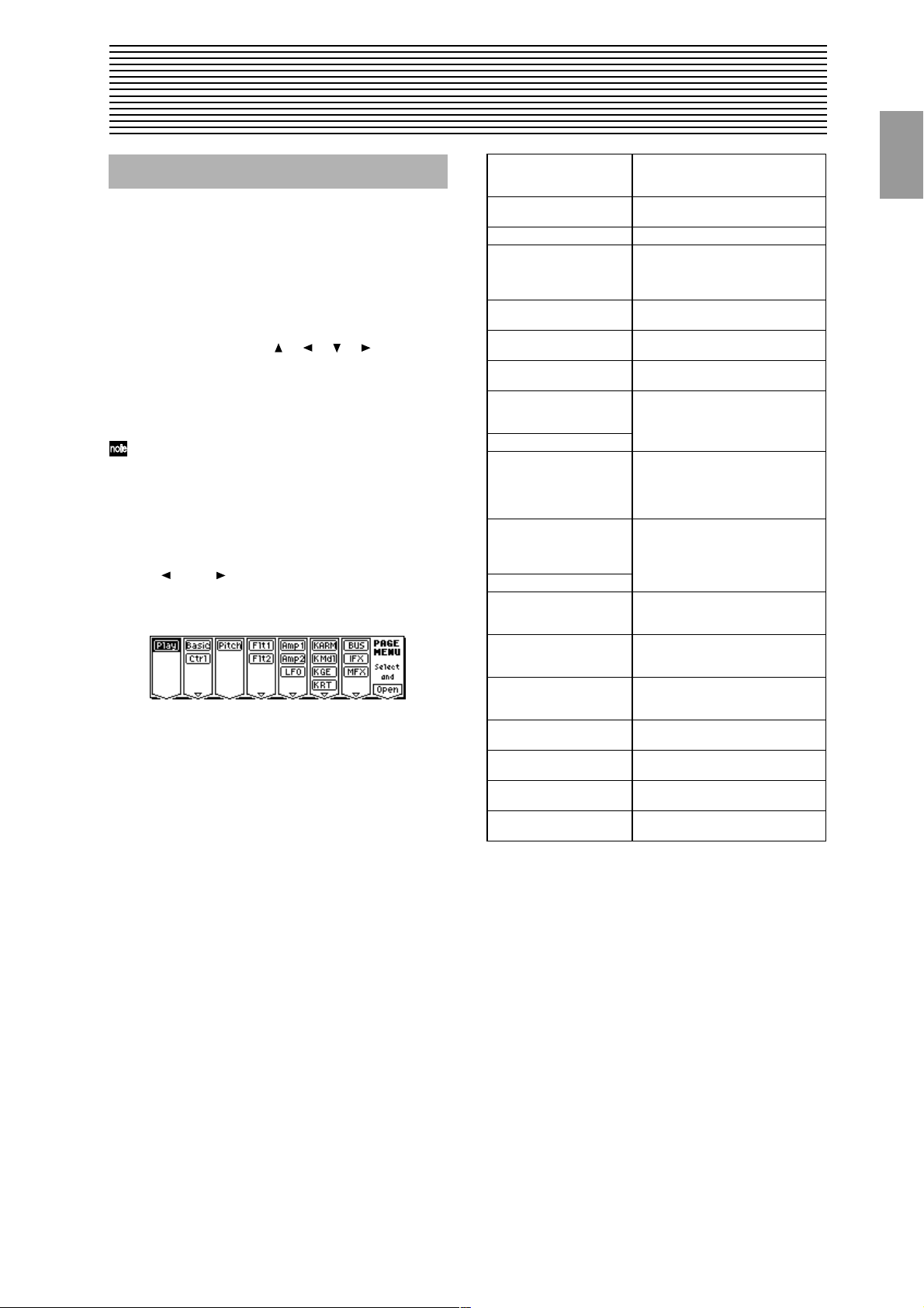
1. Program mode
PROG PAGE MENU
Use the following procedure to select the desired page
within the mode.
1 Press the [MENU] key to access the “PAGE MENU.”
The “PAGE MENU” will show an abbreviated name for
each page.
2 Use the [F1]–[F7] keys at the bottom of the page to select
the desired page. Pressing the same key repeatedly will
scroll through the various sub-pages. You can also move
by using the cursor keys [ ], [ ], [ ], [ ].
3 Press the [F8] (“Open”) key to access the page.
4 If the selected page contains two or more tab pages, press
the nearest [F1]–[F7] key below the tabs to select the
desired page.
Other ways to select a page
• You can also move to the desired page by holding down
the [MENU] key and using numeric keys [0]–[9] to enter
a two-digit page number. For example if you wish to
access the 5.3: Ed-LFOs page, hold down the [MENU]
key and consecutively press numeric keys [5] and then
[3].
• By holding down the [MENU] key and using the cursor
keys [ ](–) or [ ](+), you can step through the pages
forward or backward in the order of 1.1→2.1→2.2→3.1,
etc.
Play 1.1: Play Select and play programs. Use the Per-
Basic 2.1: Ed-Basic Set basic program parameters such as
Ctrl 2.2: Ed-Ctrl Controller settings. (
OSC 2.3: Ed-OSC This will be displayed when you select
Pitch 3.1: Ed-Pitch Pitch settings. Pitch EG settings.
Flt1 4.1: Ed-Filter1 Filter 1 (tone) settings. Filter EG set-
Flt2 4.2: Ed-Filter2 Filter 2 (tone) settings. Filter EG set-
Amp1 5.1: Ed-Amp1 Amp 1 and Amp 2 (volume) settings.
Amp2 5.2: Ed-Amp2
LFO 5.3: Ed-LFOs Type and speed settings etc. for the
Amp 5.1: Ed-Amp This will be displayed when you select
EG 5.2: Ed-EGs
KARM 6.1: Ed-KARMA KARMA GE selection, key zone
K Mdl 6.2: Ed-KARMA Mdl Module parameter settings (transpose,
K GE 6.3: Ed-KARMA GE GE parameter settings and assign-
K RT 6.4: Ed-KARMA RT KARMA RT parameters, Dynamic MIDI
BUS 7.1: Ed-BUS Select the BUS and master effect send
IFX 7.2: Ed-InsertFX Insert Effect routing, selection and set-
MFX 7.3: Ed-MasterFX Master Effect selection and settings.
formance Editor for easy editing, and to
select KARMA GE. (
Oscillator and Multisample. (
☞p.2)
☞p.7)
☞p.10)
bank F if the optional EXB-MOSS is
installed. OSC settings for the MOSS
tone generator. (
☞p.11)
(
☞p.15)
tings. (
tings. (
☞p.20)
Amp EG, pan (position) settings.
☞p.20)
(
two LFOs provided for each oscillator.
(Make settings in the pitch, filter, and
amp pages to specify the depth of the
LFO settings you make here.) (
bank F if the optional EXB-MOSS is
installed. Amp (volume) settings. Amp
EG, pan (position) settings. (
parameters, MIDI filter settings.
☞p.26)
(
pitch range of generated phrase, trigger etc.) (
ments to KARMA real-time controls
☞p.32)
(
settings. (
level for the oscillator output. (
☞p.38)
tings. (
Master EQ settings. (
☞p.11)
☞p.24)
☞p.23)
☞p.29)
☞p.34)
☞p.37)
☞p.40)
PROG
1.1
2.12.22.33.14.14.25.15.25.36.16.26.36.47.17.27.3
1
Page 12
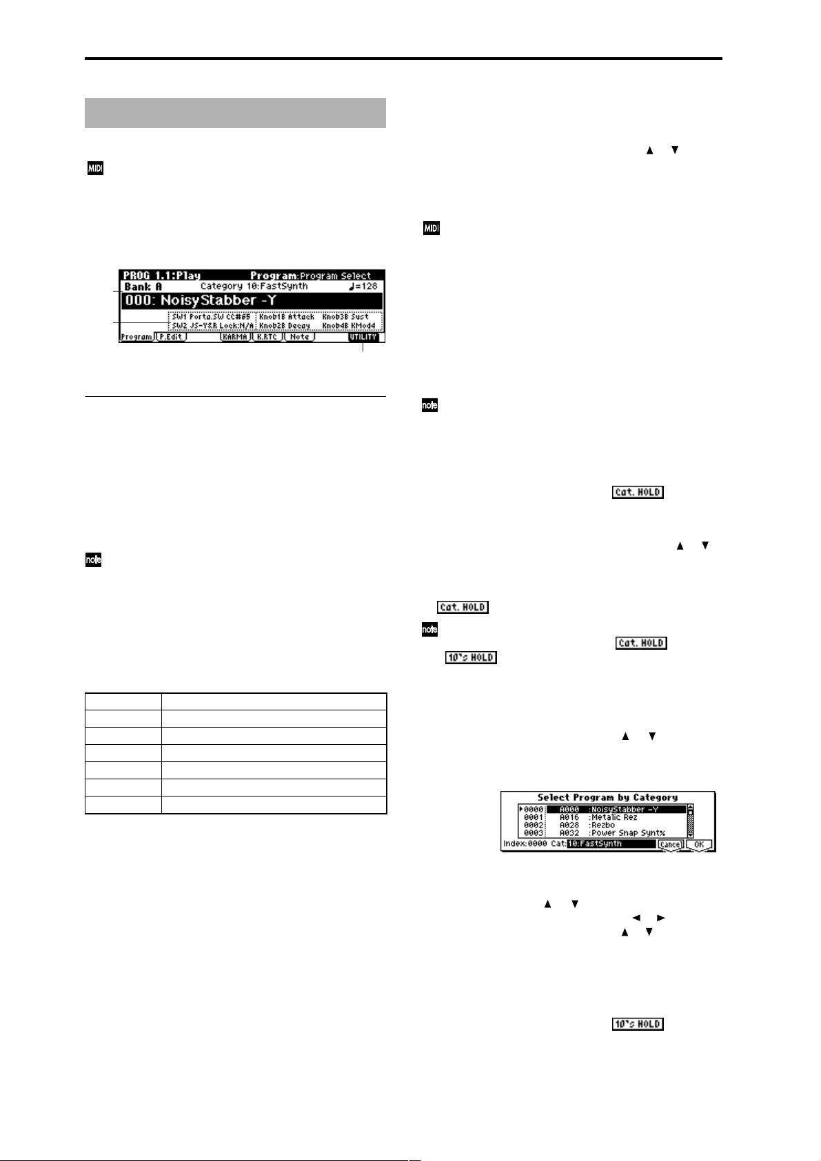
PROG 1.1: Play
In this display page you can select and play programs.
All MIDI data in PROG 1.1: Play is transmitted and
received on the Global MIDI Channel (
1a).
1.1–1: Program
1.1–1a
1.1–1b
1.1–1a: Bank, Program Select, Category, Cat. Hold,
10’s Hold, (Tempo)
Bank [Bank A...F, G, g(1)...g(9), g(d)]
This is the program bank display.
Use the BANK [A]–[G] keys to select the bank.
Bank G will cycle as follows each time you press the BANK
[G] key.
G→g(1)→g(2)→g(3)→g(4)→g(5)→g(6)→g(7)→g(8)→g(9)→
g(d)→G
Bank F can be selected if you have installed the separately sold EXB-MOSS option. When installed, the 128
special EXB-MOSS programs will be available.
The KARMA series provides rewritable banks A, B, C, D,
and E, each containing 128 programs (total 640). As for nonrewritable program areas, it provides banks G (capital programs for GM2), banks g(1)–g(9) (variation programs), and
bank g(d) (drums). (For a list of the factory-set programs,
refer to the separate VNL.)
Bank A, B for preloaded programs
Bank C, D for user programs, and EXB-PCM series programs
Bank E for preloaded programs
Bank F for EXB-MOSS programs
Bank G GM2 capital program
Bank g(1)...g(9) GM2 variation programs*
Bank g(d) GM2 drums program
☞GLOBAL 2.1–
1.1–1c
Program Select
[(A…F)0…127: name, (G…g(d))1…128: name]
Selects a program.
Choose this parameter, and use the VALUE [ ], [ ] keys,
numeric keys [0]–[9], and the [VALUE] dial to select a program.
You can select programs by category, or by using “10’s
Hold.” (
☞“Category,” “Cat. HOLD,” “10’s HOLD”)
You can transmit MIDI program changes from a con-
nected external MIDI device, or use a foot switch to
select programs. (
6.1–1a), p.232 “Foot Switch Assign List”)
Category [00...15: Name]
Selects the program category.
All programs are classified into one of sixteen categories.
You can select the desired category, and then choose programs from that category.
For the procedure of selecting programs from a category,
refer to “Cat. HOLD” and “Select by Category.”
To assign a category to each program, use the “Write
Program” (1.1–1c) dialog box. To change the name of a
category, use “Category Name Prog. 00–07, 08–15”
(
☞GLOBAL 4.1–1/2).
Cat. HOLD (Category Hold)
1 Press the [./HOLD] key to display . The cate-
gory will be held (fixed).
2 Use “Category” to select the desired category.
3 Choose “Program Select,” and use the VALUE [ ], [ ]
keys or the [VALUE] dial to select programs sequentially
within the specified category.
4 To cancel, press the [./HOLD] key twice to turn off the
display.
If you press the [./HOLD] key in PROG 1.1: Play, the
selection will cycle in the order of →
Select by Category
1 Press the [F8] (“UTILITY”) key to access the Utility
menu.
2 Press the [F7] key or the cursor keys [ ], [ ] to choose
“Select by Category,” and then press the [F8] key. The
Select Program by Category dialog box will appear. The
programs in that category will be shown in the framed list.
☞p.145 “Foot SW Assign” (GLOBAL
→ Cancel.
* For banks with no variation sounds, the GM basic sounds
will be recalled. (An * will be added at the beginning of
the program name.)
2
3 Select “Cat,” and use the Value Controller to choose the
category that includes the program you wish to select.
4 Use the cursor keys [ ], [ ] to select a program from
the list. Alternatively, you can use the [ ], [ ] keys to
select “Index,” and use the VALUE [ ], [ ] keys or
[VALUE] dial to make your selection.
5 Press the [F8] (“OK”) key to finalize your selection, or
press the [F7] (“Cancel”) key to cancel your selection.
10’s HOLD
1 Press the [./HOLD] key to display .
The first digit of the program number will be held (fixed).
Page 13
2 When you press a numeric key [0]–[9], the second digit of
the program number will be input with a single action.
You can also use the [VALUE] dial to change the second
digit place.
3 You can use the VALUE [ ], [ ] keys to change the first
digit.
4 To cancel, press the [./HOLD] key to turn off the
display.
(Tempo) [040...240, EXT]
This sets the tempo of the KARMA function. The tempo can
also be adjusted by the [TEMPO] knob.
A display of EXT indicates that the “MIDI Clock” setting
(GLOBAL 2.1–1a) has been set to External, and that the
KARMA function will synchronize to MIDI Clock messages
received from an external MIDI device.
This parameter is linked with “Te mp o” (6.1: Ed-KARMA).
1.1–1b: Program Information
It is not possible to write to banks G–g(d). If you have
edited a program from banks G–g(d) and wish to write
it, you must write to banks A–E.
5 If you wish to change the program name, press the [F5]
(“Name”) key to move to the text dialog box, and input
the name. (
6 To write the program, press the [F8] (“OK”) key. To can-
cel without writing, press the [F7] (“Cancel”) key.
When you press the [REC/WRITE] key, the Update
Program dialog box will appear. Here too, you can
write to the currently selected program.
☞BG p.39)
Select by Category
Here you can select a program by category. (☞p.2)
1.1–2: P.Edit (Performance Editor)
PROG
1.1
2.12.22.33.14.14.25.15.25.36.16.26.36.47.17.27.3
This displays the functions that are assigned to the [SW1]
key, [SW2] key, and real-time CONTROLS B mode
[ASSIGNABLE 1]–[ASSIGNABLE 4] knobs for the selected
program.
■ 1.1–1c: UTILITY
Use the following procedure to select the desired utility.
1 Press the [F8] (“UTILITY”) key to access the Utility
menu.
2 Press the [F7] key or the cursor keys [ ], [ ], [ ], [ ]
to select the desired utility.
3 Press the [F8] (“OK”) key to access the dialog box.
Utilities up to number 10 can also be selected by holding down the [ENTER] key and pressing the corresponding numeric key [0]–[9] to access the dialog box.
Write Program
If you wish to keep a program, be sure to write it into memory on this instrument.
An edited program cannot be recovered if you fail to write it
before turning off the power or selecting another program.
1 Select “Write Program” to access the dialog box.
2 The upper line shows the bank name and program name.
3 In “Category,” specify the category of the program that
you are writing. The category selected here can be used
to find this program when selecting a program in Program, Combination, Sequencer and Song Play. With the
factory settings, the program categories have been given
the names of instruments etc., but you can use “Category
Name Prog.00–07, 08–15” (GLOBAL 4.1–1/2) to modify
these category names.
4 Press “To ” to specify the writing destination.
You can also use the Bank [A]–[E] keys to select a bank.
1.1–2a
1.1–2b
1.1–2c
1.1–2a: Bank, Program Select, (Tempo)
Select a program. The bank, number, and name of the program will be displayed (
☞p.2). “ ” sets the tempo.
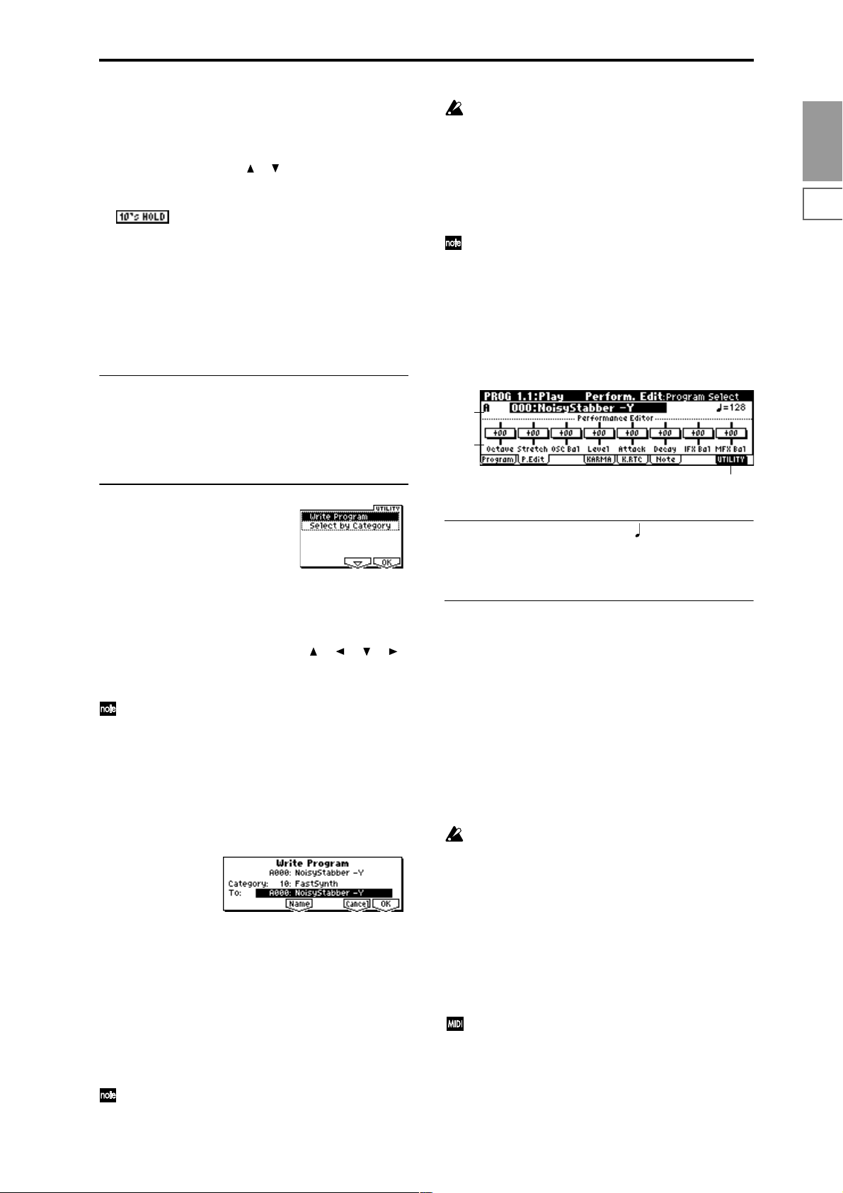
1.1–2b: Performance Editor
The Performance Editor lets you edit major program parameters without moving to the PROG 2.1–7.3 Ed (Edit) pages.
This edits multiple program parameters within the currently
selected program, allowing you to make broad adjustments
easily.
You can use the Performance Editor when you wish to
adjust the depth of effects etc. while you are playing, or to
make the initial rough settings to begin the process of creating a new sound.
Editing that you do here will affect the values of the program parameters in the edit buffer.
If you wish to keep the results of your editing, you must
write (save) the program (
Editing done using the Performance Editor will occur
within the range of the corresponding parameter. If
after using the Performance Editor to modify a value,
you move to another page or mode and then return, the
sound will remain in its edited state but the value
shown in the LCD screen by the Performance Editor
will be +00. You may do further editing from this state
if you wish.
Since editing done using the Performance Editor is not
as detailed as conventional editing, the balance
between parameters may be lost. If this occurs, use 2.1:
Ed-Basic–7.3: Ed-MasterFx to make fine adjustments.
If the “Exclusive” (GLOBAL 2.1–1b) setting is checked,
MIDI exclusive parameter changes will be transmitted
whenever you operate the Performance Editor. If these
messages are received by this instrument whose
“Exclusive” setting is checked, the Performance Editor
corresponding to that message will be modified.
☞BG p.38).
3
Page 14
Octave [–03...+00...+03]
An adjustment of +01 will raise the pitch one octave.
An adjustment of –01 will lower the pitch one octave.
This setting cannot adjust the pitch higher than 4' (feet) or
lower than 32' (feet).
Stretch (Pitch Stretch) [–12...+00...+12]
This simultaneously adjusts the Transpose and Tune of the
oscillator. This lets you produce a variety of tonal changes
and variations without loosing the character of the original
sound.
At the +00 setting, the value of the program parameters will
be unchanged.
An adjustment of +01 will lower the Transpose value by 1,
and simultaneously raise the Tune value by 100.
An adjustment of –01 will raise the Transpose value by 1,
and simultaneously lower the Tune value by 100.
However, it is not possible for the Transpose value to exceed
the range of ±12, nor the Tune value to exceed the range of
±1200.
This Performance Edit function cannot be used for
bank F.
OSC Bal (OSC Balance) [–10…+00…+10]
This adjusts the level balance between oscillators 1 and 2.
At the +00 setting, the value of the program parameters will
be unchanged.
Positive (+), settings will lower the oscillator 2 level.
With an adjustment of +10, the oscillator 2 level will be 0.
The oscillator 1 level will not change.
Negative (–) settings will lower the oscillator 1 level.
With an adjustment of –10, the oscillator 1 level will be 0.
The oscillator 2 level will not change.
For programs whose “Mode (Oscillator Mode)” (2.1–1a)
setting is Single, oscillator 2 will not sound. Only the
level of oscillator 1 will change. For a Drums program,
this performance editor will have no effect.
Level (Amp Level) [–10…+00…+10]
This adjusts the amp level.
With an adjustment of +00, the value of the program parameters will be unchanged.
Positive (+) settings will increase the amp level above the
value that was set.
With an adjustment of +10, the amp level will be 127 (maximum).
Negative (–) settings will lower the amp level below the
value that was set.
With an adjustment of –10, the amp level will be 0.
Attack (Attack Time) [–10…+00…+10]
This adjusts the attack times of the filter EG and amp EG.
With an adjustment of +00, the value of the program parameters will be unchanged.
Positive (+) settings will lengthen the attack times beyond
the values that were set.
With an adjustment of +10, the attack times will be 90.
Negative (–) settings will shorten the attack times.
With an adjustment of –10, the attack times will be 0.
When you modify “Attack Time,” the EG Start Level,
Attack Level, Start Level Modulation, and Attack Time
Modulation of the amp EG will also be adjusted simultaneously, to allow the maximum effect to be obtained.
Decay (Decay Time) [–10…+00…+10]
This adjusts the Decay Time and Slope Time of the filter EG
and amp EG.
With an adjustment of +00, the value of the program parameters will be unchanged.
Positive (+) settings will lengthen the Decay Time and Slope
Time beyond the values that were set. With an adjustment of
+10, the times will be 99.
Negative (–) settings will shorten the Decay Time and Slope
Time. With an adjustment of –10, the times will be 0.
IFX Bal (IFX Balance) [–10…+00…+10]
This adjusts the “W/D(Wet/Dry)” setting of insertion
effects 1–5 as a whole.
With an adjustment of +00, the value of the program parameters will be unchanged.
Positive (+) settings will raise the Wet levels above the program setting, and lower the Dry levels. With an adjustment
of +10, the setting will be “Wet.”
Negative (–) settings will lower the Wet levels below the
program setting, and raise the Dry levels. With an adjustment of –10, the setting will be “Dry.”
MFX Bal (MFX Balance) [–10…+00…+10]
This adjusts the master effect “Rtn1 (Return1)” and “Rtn2
(Return2)” (7.3–1a) settings as a whole.
With an adjustment of +00, the value of the program parameters will be unchanged.
Positive (+) settings will raise the return levels above the
program setting.
With an adjustment of +10, the setting will be 127 (maximum).
Negative (–) settings will lower the return levels below the
program setting.
With an adjustment of –10, the setting will be 0.
Octave Octave of OSC 1 and 2
Stretch Transpose and Tune of OSC 1 and 2
OSC Bal High Level and Low Level of OSC1 and 2
Level Amp1 Level, Amp2 Level
Attack Amp EG Attack Time, Start Level, Attack Level,
Decay AmpEG Decay Time, Slope Time of Amp 1 and 2,
IFX Bal W/D(Wet/Dry) balance of the IFX1/2/3/4/5 effects
MFX Bal Master Effect RTN1, 2(Return1, 2)
For the bank F programs that can be used when the
separately sold EXB-MOSS option is installed, different
program parameters will be adjusted.
(
☞EXB-MOSS owner’s manual & p.269 “EXB-MOSS
option”)
■ 1.1–2c: UTILITY
☞ “Write Program,” “Select by Category” (1.1–1c)
Level Modulation St, Time Modulation At of Amp 1
and 2, and Filter EG Attack Time of Filter 1 and 2
Filter EG Decay Time and Slope Time of Filter 1
and 2
4
Page 15
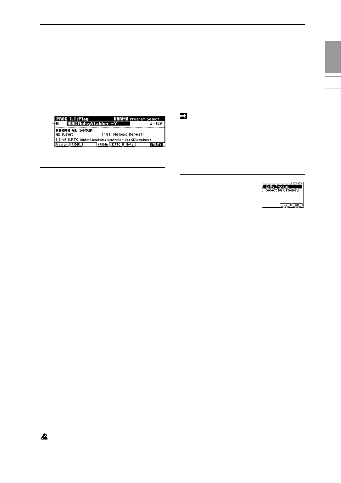
1.1–3: KARMA
Make KARMA function-related settings that will be used by
the program.
Here you can select the GE (Generated Effect) used by the
KARMA module.
Other settings are made in PROG 6.1, 6.2, 6.3, and 6.4.
To turn KARMA function on/off, use the KARMA real-time
controls [ON/OFF] key. The state of the KARMA real-time
controls [LATCH], [SCENE] key, switches [1]/[2], and knobs
[1]–[8] and the note settings/velocity of the CHORD TRIGGER
[1]–[4] keys can be saved independently for each program.
1.1–2a
1.1–3a
1.1–3b
1.1–3a: KARMA GE Setup
The phrases and patterns produced by a KARMA module
are generated by a GE (Generated Effect). Based on input
note data from the keyboard, the GE creates phrases and
patterns using numerous internal parameter settings to control the development of the note data, the rhythm, the chord
structure, the velocity etc. MIDI control changes and pitch
bend etc. can also be generated in synchronization with the
phrase or pattern. In this way you can produce phrases and
patterns in which the GE freely varies the tone or pitch. The
GE can be selected independently for each KARMA module.
In Program mode you can use one KARMA module (module
[A]). (In Combination, Sequencer, and Song Play modes, you
can use four KARMA modules (modules [A], [B], [C], [D]).)
GE Category [00: name...]
This shows the category of the GE selected for the KARMA
module.
You can use the utility menu command “Select by Category”
to select a GE by category. (
☞p.2, 1.1–3b)
If you select a GE when “Init K.RTC” is On, the KARMA
real-time controls knobs [1]–[8] will automatically be set to
the center (12 o’clock) and switches [1]/[2] will be off.
For each GE, up to sixteen parameters ideal for controlling
the phrase or pattern have been preset.
These parameters can be assigned to KARMA real-time controls knobs [1]–[8] and switches [1]/[2] and controlled. If
this is done, the settings of knobs [1]–[8] and switches [1]/
[2] will significantly change the phrase or pattern of the GE.
This setting will set knobs [1]–[8] to the center, and switches
[1]/[2] to the Off position, ensuring that the GE will function in its original preset state.
If the GE parameter “Asgn” (6.3–1(2)(3)(4)a) has been
set to Knob1–Knob8SW, SW[1], or SW[2], the GE may
not operate in its preset state, depending on the GE that
is selected. If this occurs, set the GE parameter “Asgn”
to “---.” Also, all KARMA module parameters including the GE parameter “Asgn” will be initialized when
you execute the “Initialize KARMA Module” utility
menu command in the 6.1: Ed-KARMA–6.4: EdKARMA-RT pages.
■ 1.1–3b: UTILITY
☞ “Write Program” (1.1–1c)
For details on how to select the desired utility, refer to
“PROG 1.1–1c: UTILITY.”
Select by Category
(Select Program by Category/Select by Category: GE)
When “Program Select” (1.1–2a) is selected, you can select
programs by category. (
When “GE Select” (1.1–3a) is selected, you can select a GE by
category.
For the procedure, refer to “Select by Category” (
☞p.2)
☞p.2).
PROG
1.1
2.12.22.33.14.14.25.15.25.36.16.26.36.47.17.27.3
GE Select [0000: Arp Model 1 Up/Dn...]
Here you can select a GE.
You can select from over 1000 different types.
(Tempo) [040...240, EXT]
Specifies the tempo at which KARMA will operate. (☞p.3)
Int K.RTC (KARMA Real-time Controls–Use GE’s Value)
[Off, On]
Specifies whether the settings of the KARMA real-time controls knobs [1]–[8] and switches [1]/[2] will be initialized
when you select a GE.
This allows you to hear the original state of the phrase or
pattern produced by the GE. Normally you will turn this On
when selecting a GE.
On (checked): The KARMA real-time controls knobs [1]–[8]
and switches [1]/[2] will be initialized when a GE is
selected.
Off (unchecked): The KARMA real-time controls knobs [1]–
[8] and switches [1]/[2] will not be initialized when a GE is
selected. (The state of the knobs and switches will be
applied.)
Knobs [1]–[8] and switches [1]/[2] that are not assigned
to GE parameters will not be initialized. (
1a “Asgn”)
☞PROG 6.3–
5
Page 16
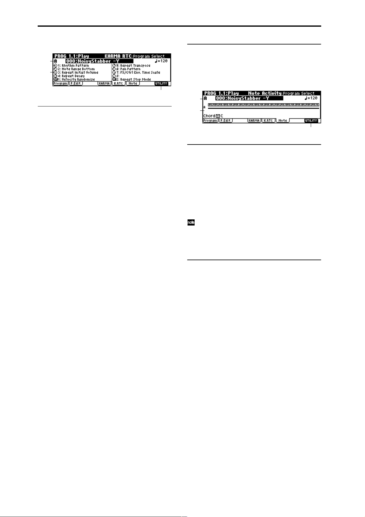
1.1–4: K.RTC (KARMA RTC)
■ 1.1–4b: UTILITY
1.1–2a
1.1–4a
1.1–4b
1.1–4a: RT Knob/SW Name
This displays the names of KARMA real-time controls knobs
[1]–[8] and switches [1]/[2], and the settings of knobs [1]–[8]
and switches [1]/[2] that are written in the program.
These names can be edited in the PROG 6.4–4/5: EdKARMA RT, Name 1/2 page.
Knobs [1]–[8] and switches [1]/[2] can be switched between
two types of settings; SCENE 1 and 2.
The settings of the knobs and switches displayed here will
also change according to the SCENE 1/2 selection.
(☞BG p.26 “Performing with the KARMA function”)
Graphic display of knobs [1]–[8] and switches [1]/[2]
When you operate a knob [1]–[8] or switch [1]/[2] to modify
the value that is written in the program, the graphic display
of that knob or switch will be highlighted in black.
When you return the knob or switch to the value that is written in the program, the graphic display will revert to its
prior state.
You can use this feature to return a knob or switch to its
original position after operating it.
To restoring the state of knobs [1]–[8] and switches [1]/[2]
You can either restore the setting while watching the graphic
display of the knob or switch, or use one of the following
methods. (This is possible only in Program and Combination modes.)
[Restoring the entire program]
Press the [COMPARE] key. All settings of the program will
be restored to the written state. (
[Restoring only the SCENE settings]
1 When you operate knobs [1]–[8] or switches [1]/[2] to
modify the values that are written in the program, the
LED of the current scene will blink.
2 At this time, you can hold down the [ENTER] key and
press the [SCENE] key to automatically restore all knobs
and switches to the values that are written. (The LED will
light.)
3 If you once again hold down the [ENTER] key and press
the [SCENE] key, all knobs and switches will return to
the state of step
[Restoring only the settings of knobs [1]–[8] and switches [1]/
[2] ]
1 When you operate a knob [1]–[8] or switch [1]/[2] to
modify the values that are written in the program, the
graphic display of that knob or switch will be highlighted in black.
2 At this time, you can hold down the [ENTER] key and
operate the knob or switch you adjusted, and it will automatically return to the value that was written.
1. (The LED will blink.)
☞BG p.15 “Compare key”)
☞ “Write Program,” “Select by Category” (1.1–1c)
1.1–5: Note (Note Activity)
1.1–2a
1.1–5a
1.1–5b
1.1–5a: Note Activity Display, Chord Name
Note Activity Display
This is a real-time display of the note-on/off states generated by the KARMA module (module [A]).
The key zone settings of the KARMA module are displayed
as a solid line. (
Chord Name
This shows the name of the chord detected by the KARMA
module.
Chord detection is affected by the key zone (PROG 6.12a: KeyZ/Thru) and “Transpose” (PROG 6.2-1a: Module Parameter) of the KARMA module, and by the
“Dynamic MIDI Destination” (PROG 6.4-3a/b/c/d)
“Chord Scan” and “Smart Scan” settings.
■ 1.1–5b: UTILITY
☞ “Write Program,” “Select by Category” (1.1–1c)
☞p.27 PROG 6.1–2a: KeyZ/Thru)
6
Page 17
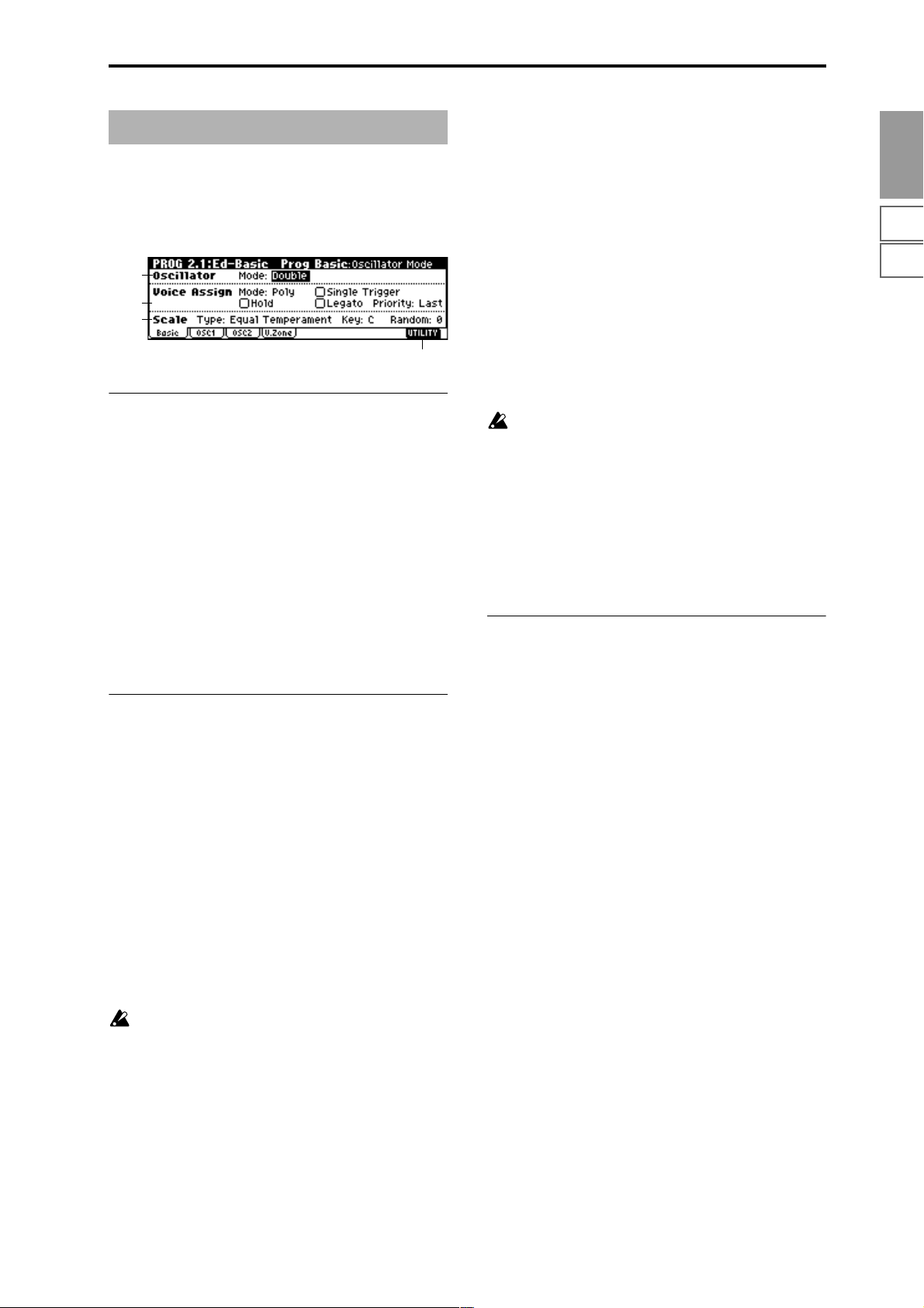
PROG 2.1: Ed–Basic
Here you can make basic settings for the oscillator(s) that
will be used.
2.1–1: Basic (Prog Basic)
2.1–1a
2.1–1b
2.1–1c
2.1–1d
2.1–1a: Oscillator
Mode (Oscillator Mode) [Single, Double, Drums]
Specifies the basic program type; whether it will use one or
two oscillators, or a drum kit.
Single: The program will use one oscillator (Oscillator 1,
Filter 1, Amplifier 1). In this case the program will have a
maximum of 62-note polyphony.
Double: The program will use two oscillators (Oscillator 1/
2, Filter 1/2, Amplifier 1/2). Allowing you to create more
complex sounds. In this case the program will have a maxi-
mum of 31-note polyphony.
Drums: The program will use one oscillator (as when Single is selected), but Oscillator 1 will be assigned a drum kit
instead of a multisample. In this case the program will have
a maximum of 62-note polyphony.
2.1–1b: Voice Assign
Mode (Voice Assign Mode) [Poly, Mono]
Poly: The program will play polyphonically, allowing you
play chords.
Mono: The program will play monophonically, producing
only one note at a time.
Hold [Off, On]
On (checked): Hold is On. Even when you take your finger
off of the key, the note will continue sounding as if it continued to be held. Unless the “Amp1 EG”, “Amp2 EG” (5.1–3a,
5.2–3) “S (Sustain Level)” is set to 0, the sound will continue
playing.
This is ideal for playing drum sounds, If you set “Mode
(Oscillator Mode)” (2.1–1a) to Drums, you should normally-
turn Hold On.
Off (unchecked): Hold is Off. Except for drum programs,
you should normally set Hold Off.
If you turn “Hold” On for a drum program, keys of the
selected drum kit whose “Enable Note Off” parameter
(GLOBAL 5.1–3a) is unchecked will be set to Hold On.
Keys that are checked will be set to Hold Off. If you
select Hold Off, the keys will be set to Hold Off regard-
less of their “Enable Note Off” setting.
Single Trigger [Off, On]
This is available when the “Mode (Voice Assign Mode)” setting is set to Poly.
On (checked): When the same note is played repeatedly, the
previous note will be silenced before the next note is
sounded, so that the notes do not overlap.
Legato [Off, On]
This is available when the “Mode (Voice Assign Mode)” setting is set to Mono.
On (checked): Legato is on. When multiple note-on’s occur,
the first note-on will retrigger the sound, and the second and
subsequent note-on’s will not retrigger.
Off (unchecked): Legato is off. Notes will always be retriggered when note-on occurs.
When legato is on, multiple note-on’s will not retrigger the
voice. If one note is already on and another note is turned on,
the first voice will continue sounding. The oscillator sound,
envelope, and LFO will not be reset, and only the pitch of the
oscillator will be updated. This setting is effective for wind
instrument sounds and analog synth-type sounds.
When legato is off, multiple note-on’s will retrigger the
voice at each note-on. The oscillator sound, envelope, and
LFO will be reset (and retriggered) according to the settings
of the program.
If “Legato” is checked, certain multisamples or keyboard locations may produce an incorrect pitch.
Priority [Low, High, Last]
This parameter is valid when “Mode (Voice Assign Mode)”
is set to Mono.
It specifies which note will be given priority to play when
two or more notes are played simultaneously.
Low: Lowest note will take priority.
High: Highest note will take priority.
Last: Last note will take priority.
2.1–1c: Scale
Type (Scale Type)
[Equal Temperament…User Octave 15]
Indicates the basic scale for the internal tone generator.
Equal Temperament: This is the most widely used scale,
where each semitone step is spaced at equal pitch intervals.
Pure Major: In this temperament, major chords of the
selected tonic will be perfectly in tune.
Pure Minor: In this temperament, minor chords of the
selected tonic will be perfectly in tune.
Arabic: This scale includes the quarter-tone scale used in
Arabic music.
Pythagoras: This scale is based on ancient Greek musical
theory, and is especially effective for playing melodies.
Werkmeister (Werkmeister III): This is an equal tempered
scale that was used since the later Baroque period.
Kirnberger (Kirnberger III): This scale was created in the
18th century, and is used mainly to tune harpsichords.
Slendro: This is an Indonesian gamelan scale in which an
octave consists of five notes.
When “Key” is set to C, use the C, D, F, G and A notes.
(Other keys will sound equal-tempered pitches.)
Pelog: This is an Indonesian gamelan scale in which an
octave consists of seven notes.
When “Key” is set to C, use the white keys. (The black keys
will sound the equal tempered pitches.)
Stretch: This tuning is used for acoustic pianos.
User All Notes: This is the full-range scale (C–1 – G9) that is
specified in “User All Notes Scale” (GLOBAL3.1–2a).
User Octave 00–15: These are the single-octave scales that
are specified in “User Octave Scale” (GLOBAL3.1–1a).
PROG
1.1
2.12.22.33.14.14.25.15.25.36.16.26.36.47.17.27.3
7
Page 18
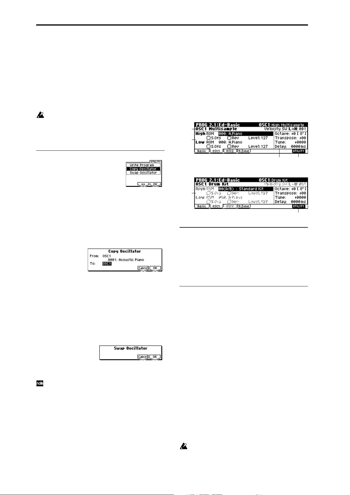
Key [C…B]
Indicates the tonic note of the specified scale.
This setting is not valid for Equal Temperament, Stretch,
and User All Notes Scale.
Random [0…7]
As this value is increased, a greater variance will be applied
to the pitch when each note is sounded. Normally you will
set this to 0. This parameter is used when simulating instruments that have natural instability in pitch, such as tapemechanism organs or acoustic instruments.
If a scale other than Equal Temperament is selected, the
combination of the selected scale and the “Key” setting
may skew the tuning of the base key (for example
A=440 Hz). If this occurs, use “Master Tune” (GLOBAL
1.1–1a) to correct the pitch.
2.1–2: OSC1
The multisample(s) (waveform) or drum kit on which the
program will be based can be selected here for oscillator 1
and/or oscillator 2.
Internal ROM contains 425 different multisamples (preset
multisamples) and 73 drum kits. If an EXB-PCM series
option has been installed, you will be able to select multisamples from the installed option.
The following illustration shows a LCD screen where
“Mode (Oscillator Mode)” (2.1–1a) has been set to Double.
If this is set to Single, the OSC2 page parameter will not
appear and cannot be set.
2.1–2a
2.1–2b
■ 2.1–1d: UTILITY
☞ “Write Program” (1.1–1c)
For details on how to select the desired utility function, refer
to “PROG 1.1–1c: UTILITY.”
Copy Oscillator
This function copies oscillator settings to the currently
selected program.
1 Select “Copy Oscillator” to access the dialog box.
2 In “From,” select the oscillator that you wish to copy and
the copy source program. You can use the Bank [A]–[G]
keys to select the bank.
3 In “To , ” select the copy destination oscillator.
4 To execute the Copy Oscillator operation, press [F8]
(“OK”) key. To cancel, press the [F7] (“Cancel”) key.
Swap Oscillator
This command exchanges the settings of oscillators 1 and 2.
1 Select “Swap Oscillator” to access the dialog box.
2 To execute the Swap Oscillator operation, press [F8]
(“OK”) key. To cancel, press the [F7] (“Cancel”) key.
This can be selected only if “Mode (Oscillator Mode)”
(2.1–1a) is Double.
2.1–2c
The following illustration shows the display when “Mode
(Oscillator Mode)” (2.1–1a) has been set to Drums.
2.1–2d
2.1–2e
2.1–2e
2.1–2a: OSC1 Multisample
Velocity SW L→H [001...127]
The oscillator 1 High and Low multisamples that you specify in “High, Low” (2.1–2b) will be switched at the velocity
value that you specify here. Notes played with a velocity
stronger than this value will be sounded by the High multisample.
2.1–2b: High, Low
Here you can select a multisample.
You can select different multisamples for High and Low, and
use velocity to switch between the two multisamples. Start
Offset, Reverse, and Level can be adjusted independently
for the High and Low multisamples.
High:
High MS Bank [ROM, EXB* ...]
High Multisample [000...424, 000...]
Specifies the bank and multisample number of the High
multisample. The multisample you select here will sounded
by velocities greater than the value of the “Velocity SW
L→H” (2.1–2a) parameter. If you do not wish to use velocity
switching, set the value to 001, and select only the High multisample.
ROM: Select a preset multisample.
Use “High Multisample” to select from 000–424.
EXB*: Multisamples from a separately sold EXB-PCM series
option board can be selected. “*” will indicate the type of
installed option.
The multisample number for “High Multisample” will
depend on the options that are installed.
The EXB* display will differ depending on the type of
option board.
8
Page 19
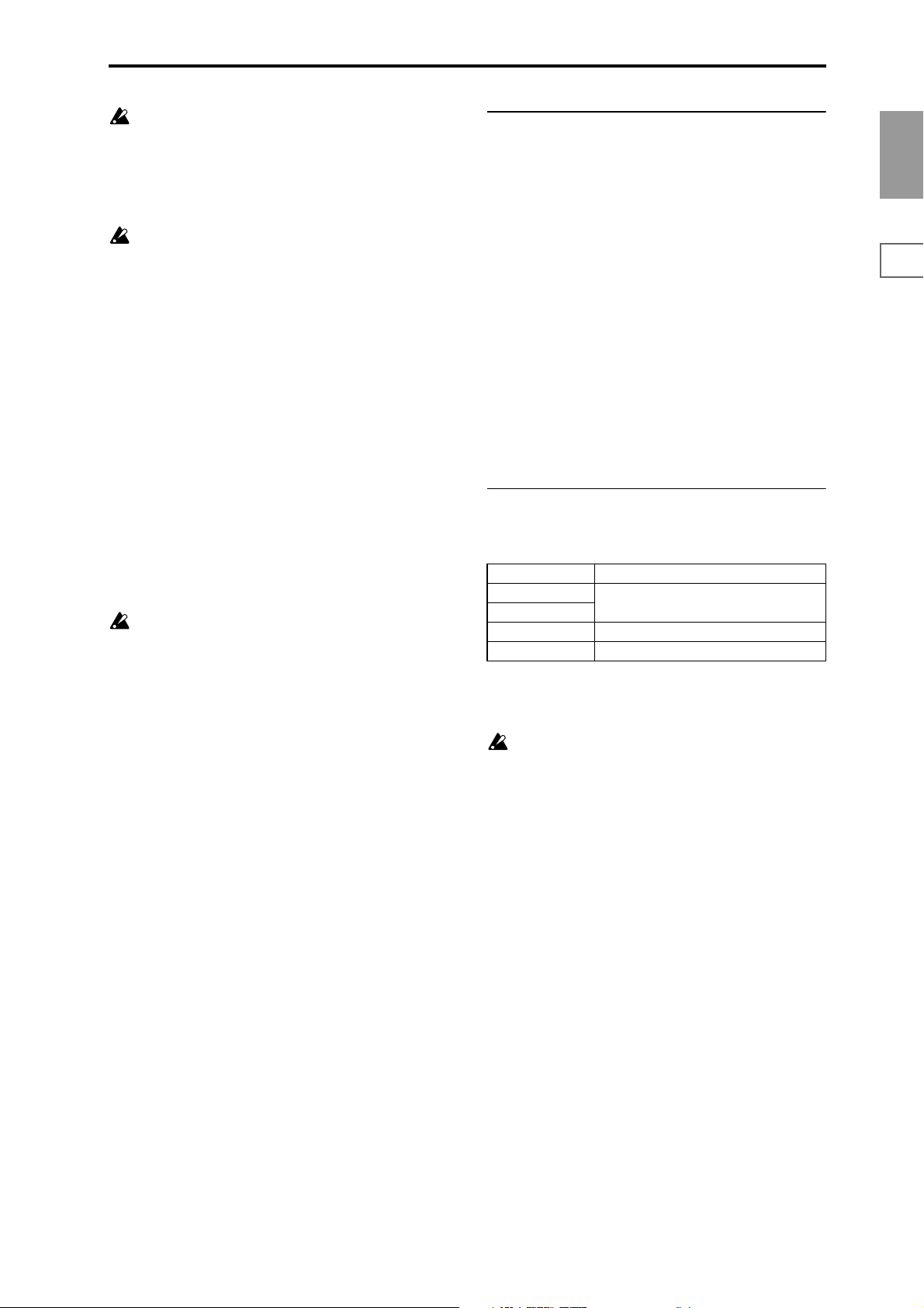
If a program that uses a multisample from a separately
sold EXB-PCM series board is selected, but the necessary multisample is not available because the corresponding EXB-PCM (expansion board) is not installed,
the “High MS Bank” field will indicate “ROM.” In this
case, the program will not sound. By re-selecting the
multisample bank, you can make the program sound.
Each multisample has an upper limit, and may not produce sound when played above that limit.
S.Ofs (High Start Offset) [Off, On]
This specifies the point at which the multisample will begin
sounding. For some multisamples this parameter will have
no effect.
On (checked): The sound will start from the start offset
location that is pre-determined for each multisample.
Off (unchecked): The sound will start from the beginning of
the multisample waveform.
Rev (High Reverse) [Off, On]
The multisample will be played in reverse. In the case of
ROM or optional (EXB-PCM series) multisamples that were
originally specified to loop, the multisample will be played
back in “one-shot” reverse mode. If the multisample was
originally set to reverse, it will playback without change.
On (checked): The multisample will playback in reverse.
Off (unchecked): The multisample will playback normally.
Level (High Level) [0...127]
Specifies the level of the multisample.
Depending on the multisample, high settings of this
parameter may cause the sound to distort when a chord
is played. If this occurs, lower the level.
2.1–2c: Octave, Transpose, Tune, Delay
Octave [–2[32’], –1[16’], +0[8’], +1[4’]]
Adjusts the pitch in octave units. The normal octave of the
multisample is 8' (feet).
Transpose [–12…+12]
Adjusts the pitch in semitone steps over a range of ±1
octave.
Tune [–1200…+1200]
Adjusts the pitch of the sample in one-cent steps (a semitone
is 100 cents) over a range of ±1 octave.
Delay [0ms…5000ms, KeyOff]
Specifies a delay time from note-on until the note will
sound.
With a setting of KeyOff, the sound will begin when note-off
occurs. This is used to create sounds such as the “click” that is
heard when a harpsichord note is released. In this case, set the
“Amp1 EG”, “Amp2 EG” (5.1–3a, 5.2–3) “S (Sustain Level)”
parameter to 0.
2.1–2d: OSC1 Drum Kit
Drum Kit [00(A/B)...63(User), 64(GM)...72(GM)]
Select a drum kit.
00 (A/B)–15 (A/B) Preset drum kits.
16 (C)–31 (C)
32 (D)–47 (D)
48 (User)–63 (User) for user drum kits
64 (GM)–72 (GM) ROM preset drum kits compatible with GM2.
for user drum kits, EXB-PCM series drum kits
PROG
1.1
2.12.22.33.14.14.25.15.25.36.16.26.36.47.17.27.3
Low:
Specifies the OSC1 Low multisample.
The Low multisample will sound when the velocity is less
than the “Velocity SW L→H” (2.1–2a) setting.
Low MS Bank [ROM. EXB*...]
Low Multisample [000...424, 000...]
S.Ofs (Low Start Offset) [Off, On]
Rev (Low Reverse) [Off, On]
Level (Low Level) [000...127]
☞ Refer to the corresponding item in “High.”
Octave [–2[32’], –1[16’], +0[8’], +1[4’]]
Adjusts the pitch in octave units. When using a drum kit, set
the Octave to 8'.
When editing a drum program, you must set this
parameter to 8'. With other settings, the sounds of the
drum kit will be assigned to the wrong notes of the keyboard.
Transpose [–12…+12]
This adjusts the location of the instruments in the selected
drum kit. Unless you need to change this, leave it at 0.
Tune [–1200…+1200]
This adjusts the pitch in one-cent units.
The pitch of each drum kit can be adjusted in GLOBAL 5.1:
DKit.
Delay [0ms…5000ms, KeyOff]
This specifies a delay time from note-on until the sound will
begin.
With a setting of KeyOff, the sound will begin when noteoff occurs. In this case, set the “Amp1 EG” parameter “S
(Sustain Level)” (5.1–3a) to 0.
9
Page 20
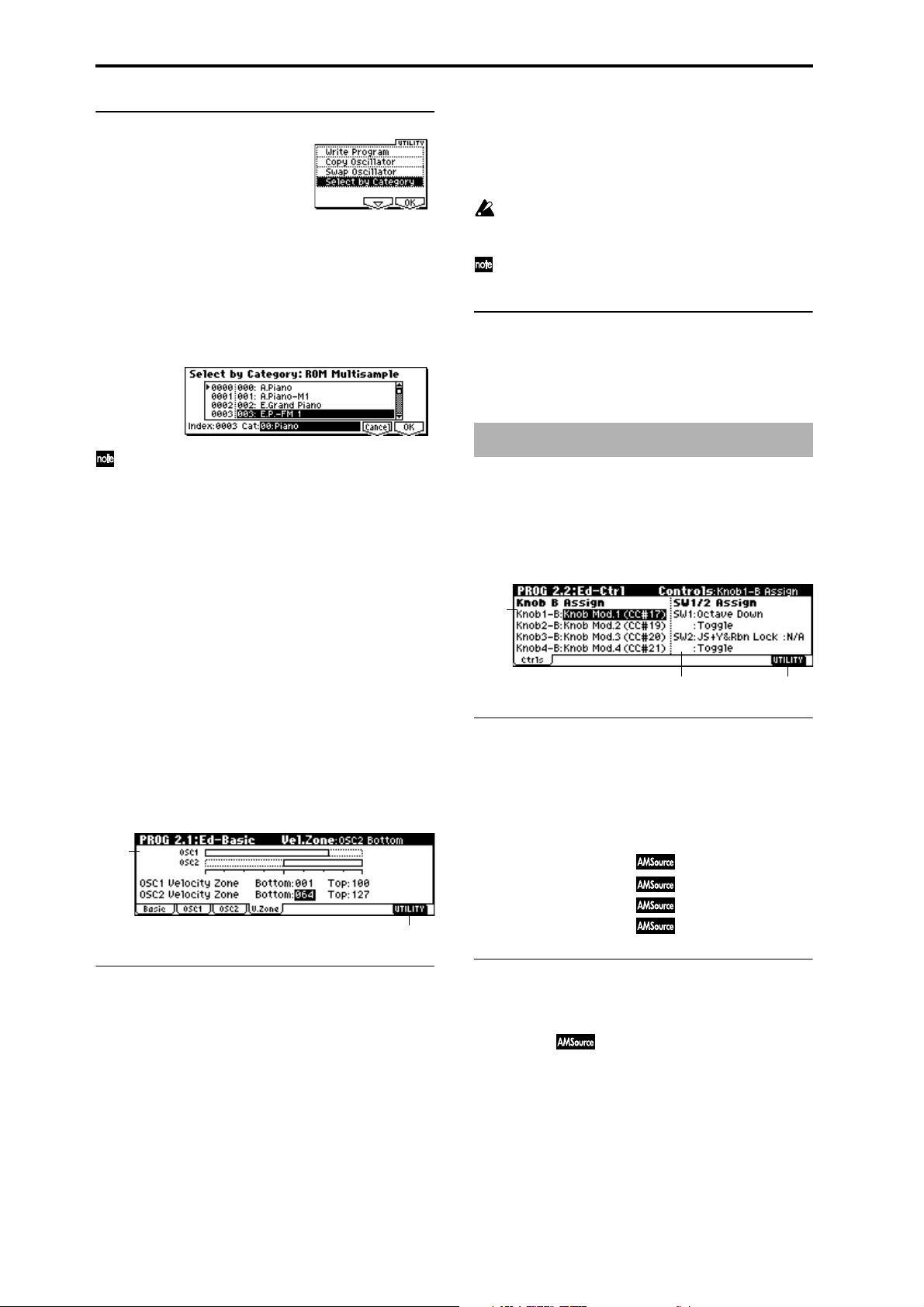
■ 2.1–2e. UTILITY
☞ “Write Program” (1.1–1c), “Copy Oscillator,” “Swap
Oscillator” (2.1–1d)
For details on how to select the desired utility function, refer
to “PROG 1.1–1c: UTILITY.”
OSC2 Bottom [001...127]
Sets the minimum velocity value that will sound oscillator 2.
OSC2 Top [001...127]
Sets the maximum velocity value that will sound oscillator 2.
It is not possible to set the Bottom Velocity greater than
the Top Velocity, nor the Top Velocity less than the Bottom Velocity.
You can also input a value by playing a note on the keyboard while you hold down the [ENTER] key.
Select by Category
Selects multisamples by category.
For the procedure, refer to “Select by Category” (
This command is valid if “Mode (Oscillator Mode)”
(2.1–1a) is Single or Double, and you are selecting the
“High MS Bank,” “High Multisample,” “Low MS
Bank,” or “Low Multisample” of OSC1 or OSC2 for
which ROM was selected for “High MS Bank” or “Low
MS Bank.”
☞p.2).
2.1–3: OSC2
This will appear when “Mode (Oscillator Mode)” (2.1–1a) is
set to Double.
For details on the settings and function of the parameter,
refer to “2.1–2: OSC1.”
2.1–4: V.Zone (Velocity Zone)
Specifies the range of velocities that will sound oscillator 1
and 2. By using these settings in conjunction with the
“Velocity SW L→H” (2.1–2a) setting of each oscillator, you
can specify the velocity ranges for the High and Low multisamples or drum kits.
2.1–4a
2.1–4b
■ 2.1–4b: UTILITY
☞ “Write Program” (1.1–1c), “Copy Oscillator,” “Swap
Oscillator” (2.1–1d)
PROG 2.2: Ed–Ctrl
These settings specify the B-mode functions of real-time
CONTROLS knobs [1]–[4] in Program mode, and the functions of the [SW1] key, the [SW2] key.
2.2–1: Ctrls (Controls)
2.2–1a
2.2–1c2.2–1b
2.2–1a: Knob B Assign
Here you can assign functions (mainly various types of control change) to the B mode of the REAL-TIME CONTROLS
knobs [1]–[4] (
List”).
The functions you set here will take effect when you operate
the REAL-TIME CONTROLS knobs [1]–[4] in B-mode.
Knob1–B (Knob1–B Assign) [Off...MIDI CC#95]
Knob2–B (Knob2–B Assign) [Off...MIDI CC#95]
Knob3–B (Knob3–B Assign) [Off...MIDI CC#95]
Knob4–B (Knob4–B Assign) [Off...MIDI CC#95]
☞p.231 “Realtime Control Knobs B Assign
2.1–4a: OSC 1/2 Velocity Zone
OSC1 Bottom [001...127]
Sets the minimum velocity value that will sound oscillator 1.
OSC1 Top [001...127]
Sets the maximum velocity value that will sound oscillator
1.
10
2.2–1b: SW1/2 Assign
These settings assign functions to [SW1] and [SW2] keys
☞p.230 “SW1, SW2 Assign List”).
(
SW1 Assign [Off, ..., AfterT Lock]
Here you can assign a function to the [SW1] key.
The on/off status of the switch is saved when the program is
written. When you change the function, it will be reset to the
“off” state.
Page 21
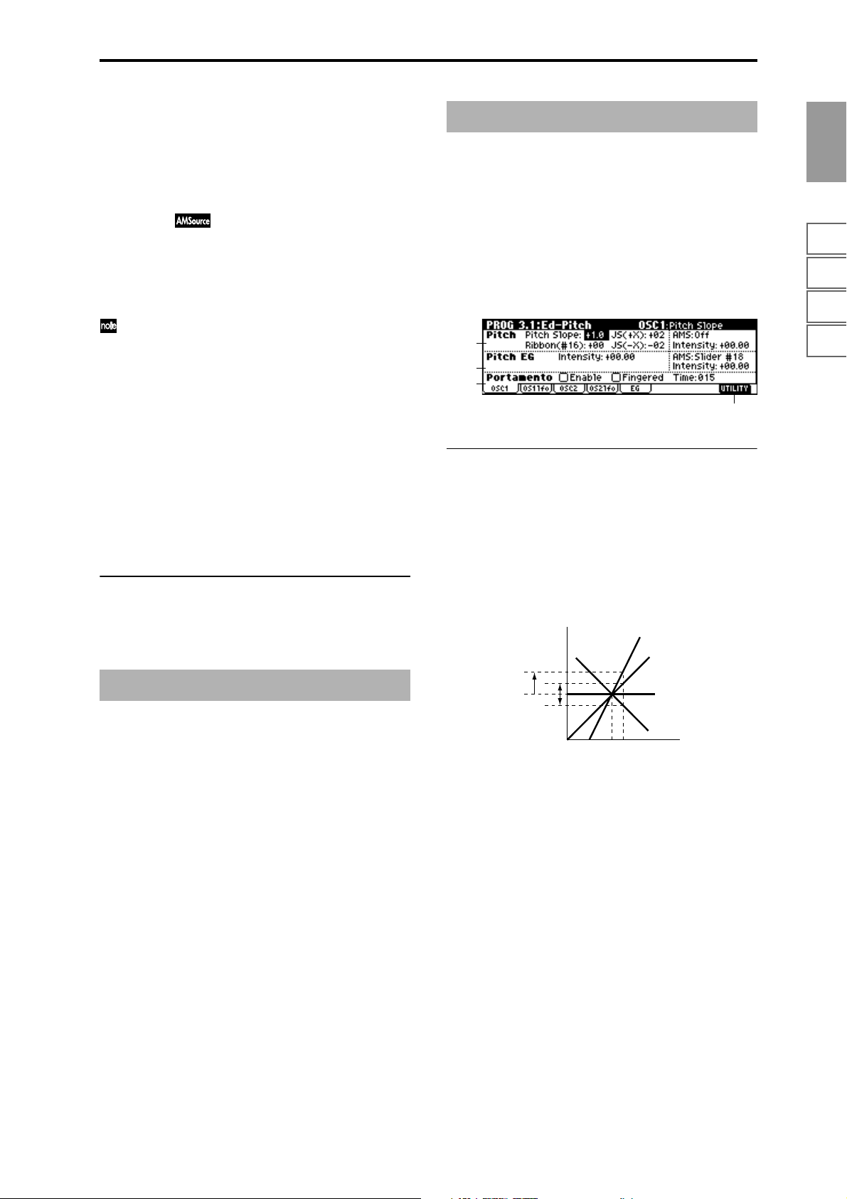
SW1 Mode [Toggle, Momentary]
Specifies the on/off state that will occur when you press the
[SW1] key in 1.1:Play.
Toggle: The key will alternate on/off each time you press
[SW1] key).
Momentary: The key will be on only while you continue
holding [SW1] key).
SW2 Assign [Off, ..., AfterT Lock]
SW2 Mode [Toggle, Momentary]
Here you can assign a function to [SW2] key.
The functions that can be assigned to [SW2] key are the
same as for [SW1] key, with the exception of SW2 Mod.
(CC#81) instead of SW1 Mod. (CC#80).
Although the following values can be selected for “SW1
Assign” and “SW2 Assign,” they will have no effect in
actuality.
Data is compatible between this instrument and the
TRITON/TRITONpro/TRITONproX (keyboard models of the TRITON and the TRITON-Rack). Programs
created on this instrument can be used by a TRITON
keyboard model, and vice versa.
In order to maintain compatibility, you are able to set
these “invalid” parameters on this instrument.
N/A indicates Not Available.
Ribbon Lock : N/A
JS X&Rbn Lock : N/A
JS+Y&Rbn Lock : N/A
JS-Y&Rbn Lock : N/A
■ 2.2–1c: UTILITY
☞ “Write Program” (1.1–1c), “Copy Oscillator,” “Swap
Oscillator” (2.1–1d)
PROG 2.3: Ed–OSC
This page will be displayed when you select bank F if the
separately sold EXB-MOSS option is installed.
☞EXB-MOSS owner’s manual & p.269 “EXB-MOSS
(
option”)
PROG 3.1: Ed–Pitch
Here you can make pitch modulation settings for oscillators
1 and 2.
3.1–1: OSC1
Specifies how the keyboard location will affect the pitch of
oscillator 1, and select the controller that will modify the
pitch and the depth of this effect. Here you can also specify
the amount of pitch change caused by the pitch EG, and set
the portamento on/off and mode settings.
3.1–1a
3.1–1b
3.1–1c
3.1–1d
3.1–1a: Pitch
Pitch Slope [–1.0…+2.0]
Normally you will leave this at +1.0.
Positive (+) values will cause the pitch to rise as you play
higher on the keyboard, and negative (–) values will cause
the pitch to fall as you play higher on the keyboard.
With a value of 0, there will be no change in pitch, and the
C4 pitch will sound regardless of the keyboard location you
play.
How the Pitch Slope and pitch are related
Pitch
2oct
1oct
1oct
Ribbon (#16) [–12…+12]
Specifies in semitone units how the pitch will change when
CC#16 is received (or when the ribbon controller is pressed
on this instrument or other instrument connected to MIDI
IN connector).
12 half-steps equal one octave. With positive (+) values, the
pitch will rise when you press the right half of a ribbon controller. With negative (–) values, the pitch will fall.
For example, with a setting of +12, pressing the far right
edge of the ribbon controller will raise the pitch one octave.
With a setting of –12, pressing the far right edge of the ribbon controller will lower the pitch one octave.
At the center of the ribbon controller, the original pitch will
remain, so you can use this in conjunction with pressing the
ribbon at its right edge to simulate the “hammering-on”
techniques used by guitarists.
C4 C5
+2
+1
0
–1
Key
PROG
1.1
2.12.22.33.14.14.25.15.25.36.16.26.36.47.17.27.3
11
Page 22
JS (+X) [–60…+12]
Specifies how the pitch will change when the joystick is
moved all the way to the right.
A setting of 12 produces 1 octave of change.
For example, if you set this to +12 and move the joystick all
the way to the right, the pitch will rise one octave above the
original pitch.
JS (–X) [–60…+12]
Specifies how the pitch will change when the joystick is
moved all the way to the left. (
☞p.224)
A setting of 12 produces 1 octave of change.
For example, if you set this to –60 and move the joystick all
the way to the left, the pitch will fall five octaves below the
original pitch. This can be used to simulate the downward
swoops that a guitarist produces using the tremolo arm.
AMS (Pitch AMS) [Off, (FEG, AEG, EXT)]
Selects the source that will modulate the pitch of oscillator 1
(
☞p.222 “AMS List”).
Intensity (AMS Intensity) [–12.00…+12.00]
Specifies the depth and direction of the effect produced by
“AMS (Pitch AMS).”
With a setting of 0, no modulation will be applied. With a
setting of 12.00, the pitch will change up to one octave.
For example if you set “AMS” to AfterT and apply pressure
to the keyboard, the pitch will rise if this parameter is set to
a positive (+) value, or fall if this parameter is set to a nega-
tive (–) value. The range is a maximum of one octave.
(
☞p.224)
3.1–1b: Pitch EG
3.1–1c: Portamento
This turns the portamento effect (smooth change in pitch
from one note to the next) on/off, and specifies how it will be
applied. If [SW 1] or [SW2] are set to Porta.SW(CC#65), turning SW1 or SW2 on/off will apply portamento (
☞p.222
“AMS List” SW1 CC#80, SW2 CC#81, Prta.SWCC#65).
Portamento will also be switched when CC#65
(Portamento SW) is received.
Enable (Porta. Enable) [Off, On]
On (checked): Portamento will be applied.
Off (unchecked): Portamento will not be applied.
Fingered (Porta. Fingered) [Off, On]
This parameter is available when “Enable (Porta. Enable)” is
checked.
On (checked): Portamento will be applied when you continue holding the previous note as you press the next note
(legato playing).
Off (unchecked): Portamento will always be applied,
regardless of how you play.
Time (Porta. Time) [000...127]
This parameter is available when “Enable (Porta. Enable)” is
checked.
This sets the portamento time. Increasing the value will produce a slower change in pitch.
■ 3.1–1d: UTILITY
☞ “Write Program” (1.1–1c), “Copy Oscillator,” “Swap
Oscillator” (2.1–1d)
Intensity [–12.00…+12.00]
Specifies the depth and direction of the modulation that the
pitch EG specified in “EG (Pitch EG)” (3.1–5) page will
apply to the pitch.
With a setting of 12.00, the pitch will change a maximum of
±1 octave.
AMS (Pitch EG AMS) [Off, (KT, EXT)]
Selects the source that will control the pitch modulation
applied by the pitch EG (
☞p.222 “AMS List”).
Intensity (AMS Intensity) [–12.00…+12.00]
Specifies the depth and direction of the effect that “AMS
(Pitch EG AMS)” will have.
For example, if you set “AMS (Pitch EG AMS)” to Velocity
and set this value to +12.00, the velocity will control the
range of pitch change produced by the pitch EG in a range
of ±1 octave (
change will draw closer to the pitch EG levels.
Pitch change (level)
Note-on
Softly played
(Intensity (Pitch EG) setting)
“Intensity” and “AMS (Pitch EG AMS)” will be added
to determine the depth and direction of the pitch modulation applied by the pitch EG.
☞p.224). As you play more softly, the pitch
Note-off
Note-on
Note-off
Strongly played with
a positive (+) value
Note-on
Strongly played with a
negative (–) value
Note-off
3.1–2: OS1lfo (OSC1 LFO)
Specifies the amount of pitch change produced by LFO1 and
LFO2 for oscillator 1.
3.1–2a
3.1–2b
3.1–2a: Pitch LFO1/2 Modulation
LFO1:
Intensity (LFO1 Intensity) [–12.00…+12.00]
Specifies the depth and direction of the pitch modulation
applied by the OSC 1 LFO1 settings you made in
“OS1LFO1” page (5.3–1).
With a setting of 12.00, a maximum of ±1 octave of pitch
modulation will be applied. Negative (–) values will invert
the LFO waveform.
JS+Y Int. (LFO1 JS+Y Int.) [–12.00…+12.00]
Specifies the depth and direction of the effect that joystick
movement in the +Y direction (away from yourself) will
have on the pitch modulation applied by the OSC1 LFO1.
12
Page 23

As this value is increased, moving the joystick in the +Y
direction will cause the OSC1 LFO1 to produce deeper pitch
modulation. With a setting of 12.00 a maximum of ±1 octave
of pitch modulation will be applied. Negative (–) values
will invert the LFO waveform.
AMS (LFO1 AMS) [Off, (PEG, FEG, AEG, KT, EXT)]
Indicates the source that will control the depth of pitch modulation produced by the OSC1 LFO1 (
☞p.222 “AMS List”).
Intensity (AMS Intensity) [–12.00…+12.00]
Specifies the depth and direction of the effect that “AMS
(LFO1 AMS)” will have.
With a setting of 0, modulation will not be applied. With a
setting of 12.00, the OSC1 LFO1 will apply a maximum of ±1
octave of pitch modulation. Negative (–) settings will invert
the LFO waveform.
For example if “AMS” is set to AfterT and you apply pressure to the keyboard, a positive (+) setting of this parameter
will cause the pitch modulation created by OSC1 LFO1 to be
applied with the normal phase, and a negative (–) setting
will cause the LFO to be applied with inverted phase.
The “Intensity (LFO1 Intensity),” “JS+Y Int. (LFO1 JS+Y
Int.)” and “AMS (LFO1 AMS)” settings will be added to
determine the depth and direction of the pitch modulation
applied by OSC1 LFO1 (
☞p.224).
LFO2:
Intensity (LFO2 Intensity) [–12.00…+12.00]
JS+Y Int. (LFO2 JS+Y Int.) [–12.00…+12.00]
AMS (LFO2 AMS) [Off, (PEG, FEG, AEG, KT, EXT)]
Intensity (AMS Intensity) [–12.00…+12.00]
Refer to the preceding section “LFO1.”
■ 3.1–2b: UTILITY
☞ “Write Program” (1.1–1c), “Copy Oscillator,” “Swap
Oscillator” (2.1–1d)
3.1–5: EG (Pitch EG)
Here you can make settings for the pitch EG, which creates
time-variant changes in the pitch of oscillators 1 and 2.
The depth of pitch change produced by these EG settings on
oscillator 1 (2) is adjusted by “Pitch EG” (3.1–1b, 3.1–3).
3.1–5a
3.1–5b
3.1–5c
3.1–5a: Pitch EG
These settings specify how the pitch will change over time.
L (Level):
These parameters specify the amount of pitch change.
The actual amount of pitch change will depend on the
“Pitch EG” (3.1–1b, 3.1–3) parameter “Intensity.” For example with an “Intensity” setting of +12.00, a “Level” setting of
+99 would raise the pitch one octave, and a “Level” setting
of –99 would lower the pitch one octave.
S (Start Level) [–99…+99]
Specifies the amount of pitch change at note-on.
A (Attack Level) [–99…+99]
Specifies the amount of pitch change when the attack time
has elapsed.
R (Release Level) [–99…+99]
Specifies the amount of pitch change when the release time
has elapsed.
T (Time):
These parameters specify the time over which the pitch
change will occur.
3.1–5d
PROG
1.1
2.12.22.33.14.14.25.15.25.36.16.26.36.47.17.27.3
3.1–3: OSC2
Specifies how the keyboard location will affect the pitch of
oscillator 2, and select the controller that will affect the pitch
and specify the depth of control. Here you can also specify
the amount of pitch change produced by the pitch EG, and
set the portamento on/off status and mode. For details on
each parameter, refer to the preceding “3.1–1: OSC1.”
3.1–4: OS2lfo (OSC2 LFO)
Specifies the amount of pitch change produced by LFO1 and
LFO2 for oscillator 1. For an explanation of each parameter,
refer to the preceding “3.1–2: OS1lfo.”
A (Attack Time) [0…99]
Specifies the time over which the pitch will change from
note-on until it reaches the pitch specified as the attack level.
D (Decay Time) [0…99]
Specifies the time over which the pitch will change after
reaching the attack level until it reaches the normal pitch.
R (Release Time) [0…99]
Specifies the time over which the pitch will change from
note-off until it reaches the pitch specified as the release
level.
Time-varying pitch settings (when Pitch EG Intensity = +12.00)
+99 = approximately 1 octave
0 = pitch when
key is held
(sustained)
Start Level
–99 = approximately 1 octave
Note-on
Attack
Time
Attack Level
Decay
Time
Note-off
Release Time
Time
Release Level
13
Page 24
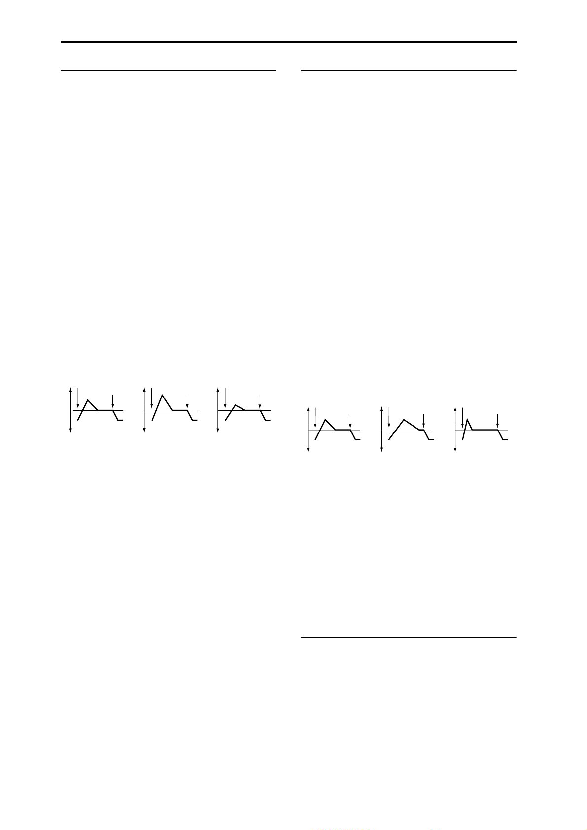
3.1–5b: Level Mod. (Level Modulation)
3.1–5c: Time Mod. (Time Modulation)
These settings allow the pitch EG “L (Level)” parameters to
be controlled by alternate modulation.
AMS1 (Level Mod. AMS1) [Off, (KT, EXT)]
Selects the source that will control the pitch EG “L (Level)”
parameters (
☞p.222 “AMS List”).
I (AMS1 Intensity) [–99…+99]
Specifies the depth and direction of the effect applied by
“AMS1 (Level Mod. AMS1).”
With a setting of 0, the levels specified by “Pitch EG” (3.1–
5a) will be used.
For example, if “AMS1 (Level Mod. AMS1)” is SW1 #80,
pressing the [SW1] key to turn it on will change the “Level”
parameters of the Pitch EG. (“SW1/2 Assign”: 2.2–1b) to
SW1 Mod. (CC#80). As the absolute value of “I (AMS1
Intensity)” is increased, the pitch EG levels will change more
greatly when the [SW1] key is turned on. The direction of
the change is specified by “S (AMS1 SW Start)” and “A
(AMS1 SW Attack).” When the [SW1] key is turned off, the
pitch EG levels will return to their own settings.
If “AMS1” is set to Velocity, increasing the absolute value of
“Intensity” will produce increasingly wider change in pitch
EG levels for strongly-played notes. The direction of the
change is specified by “S (AMS1 SW Start)” and “A (AMS1
SW Attack).” As you play more softly, the pitch change will
draw closer to the pitch EG levels.
Pitch EG change (level) (AMS=SW1/Velocity, Intensity= positive (+) value)
Note-on
Note-off
Note-on
Note-off
Note-on
Note-off
These parameters let you use alternate modulation to control the “T (Time)” parameters of the pitch EG.
AMS (Time Mod. AMS) [Off, (KT, EXT)]
Indicates the source that will control the “T (Time)” parameters of the pitch EG (
☞p.222 “AMS List”).
I (AMS Intensity) [–99…+99]
Specifies the depth and direction of the effect that “AMS
(Time Mod. AMS)” will have.
With a setting of 0, the pitch EG times will be just as specified by the “Pitch EG” (3.1–5a) settings.
The alternate modulation value at the moment that the EG
reaches each point will determine the actual value of the EG
time that comes next.
For example, the decay time will be determined by the alternate modulation value at the moment that the attack level is
reached.
When this parameter is set to values of 16, 33, 49, 66, 82, or
99, the specified EG times will speed up as much as 2, 4, 8,
16, 32, or 64 times respectively (or slowed down to 1/2, 1/4,
1/8, 1/16, 1/32, or 1/64 of the original time).
For example if “AMS (Time Mod. AMS)” is set to Velocity,
increasing the absolute value of “I (AMS Intensity)” will
allow strongly-played notes to increase the changes in pitch
EG “T (Time)” values. The direction of the change is speci-
fied by “A (AMS SW Attack)” and “D (AMS SW Decay).” As
you play more softly, the pitch EG times will more closely
approach the actual settings of the pitch EG.
Pitch EG changes (Time) (AMS = Velocity, Intensity = positive (+) value)
Note-on
Note-off
Note-on
Note-off
Note-on
Note-off
A note played softly with “S”
set at 0, “A” set to +, and
SW1 turned on (the settings
of 3.1–5a: Pitch EG)
A note played strongly with
“S” set to 0, “A” set to +, and
SW1 turned on
A note played strongly with
“S” set to 0, “A” set to –, and
SW1 turned on
S (AMS1 SW Start) [–, 0, +]
Specifies the direction of change in “S (Start Level)” caused
by “AMS1 (Level Mod. AMS1).” If “I (AMS1 Intensity)” is a
positive (+) value, a setting of + will raise the EG level, and
a setting of – will decrease it. With a setting of 0 there will be
no change.
A (AMS1 SW Attack) [–, 0, +]
Specifies the direction of change in “A (Attack Level)”
caused by “AMS1 (Level Mod. AMS1).” If “I (AMS1 Intensity)” is a positive (+) value, a setting of + will raise the EG
level, and a setting of – will decrease it. With a setting of 0
there will be no change.
AMS2 (Level Mod. AMS2) [Off, (KT, EXT)]
I (AMS2 Intensity) [–99…+99]
S (AMS2 SW Start) [–, 0, +]
A (AMS2 SW Attack) [–, 0, +]
Refer to the preceding paragraphs “AMS1 (Level Mod.
AMS1)”–“A (AMS1 SW Attack).”
A note played softly with “A”
set to + and “D” set to +
(settings of 3.1–5a: Pitch EG)
A note played strongly with
“A” set to + and “D” set to +
A note played strongly with
“A” set to – and “D” set to –
A (AMS SW Attack) [–, 0, +]
Specifies the direction in which “AMS (Time Mod. AMS)”
will affect the “A (Attack Time).” With positive (+) values of
“I (AMS Intensity),” a setting of + will cause the time to be
lengthened, and a setting of – will cause the time to be shortened. With a setting of 0 there will be no change.
D (AMS SW Decay) [–, 0, +]
Specifies the direction in which “AMS (Time Mod. AMS)”
will affect the “D (Decay Time).” With positive (+) values of
“I (AMS Intensity),” a setting of + will cause the time to be
lengthened, and a setting of – will cause the time to be shortened. With a setting of 0 there will be no change.
■ 3.1–5d: UTILITY
☞ “Write Program” (1.1–1c), “Copy Oscillator,” “Swap
Oscillator” (2.1–1d)
14
Page 25
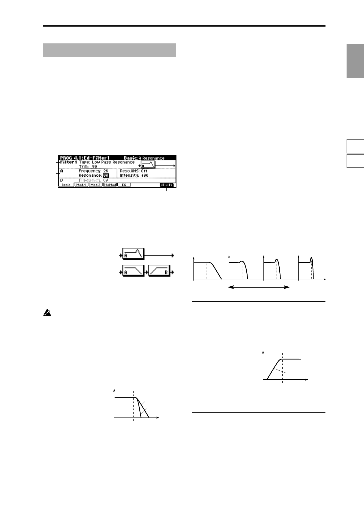
PROG 4.1: Ed–Filter1
Frequency (A Frequency) [00…99]
Specifies the cutoff frequency of filter 1A.
Indicates settings for filter 1 that controls the tone of oscillator 1. You can select either a 24 dB/oct low pass filter with
resonance, or a 12 dB/oct low pass filter and 12 dB/oct high
pass filter connected in series.
When “Mode (Oscillator Mode)” (2.1–1a) is Single, Drums
you can use filter 1. When it is Double, you can use filters 1
and 2. In the case of Single, Drums the filter 2 pages cannot
be selected.
4.1–1: Basic
Here you can specify the basic type for filter 1 (used by oscillator 1), and set the cutoff frequency and resonance.
4.1–1a
4.1–1b
4.1–1c
4.1–1d
4.1–1a: Filter1
Type (Filter1 Type)
[Low Pass Resonance, Low Pass & High Pass]
Indicates the type for filter 1.
Low Pass Resonance: 24 dB/octave low
pass filter with resonance
Low Pass & High Pass: 12 dB/octave
low pass filter and 12 dB/octave high pass
filter in series
Resonance (A Resonance) [00…99]
This emphasizes the overtone components that lie in the
region of the cutoff frequency specified by “Frequency (A
Frequency),” producing a more distinctive sound. Increasing this value will produce a stronger effect.
Reso.AMS (Resonance AMS)
[Off, (PEG, FEG, AEG, LFO, KT, EXT)]
Indicates the source that will control the “Resonance (A Resonance)” level (
☞p.222 “AMS List”).
Intensity (AMS Intensity) [–99…+99]
Specifies the depth and direction of the effect that “Reso.
AMS (Resonance AMS)” will have on the resonance level
specified by “Resonance (A Resonance).”
For example, if Velocity has been selected, changes in key-
board velocity will affect the resonance.
With positive (+) values, the resonance will increase as you
play more strongly, and as you play more softly the resonance will approach the level specified by the “Resonance
(A Resonance)” setting.
With negative (–) values, the resonance will decrease as you
play more strongly, and as you play more softly the resonance will approach the level specified by the “Resonance
(A Resonance)” setting.
The resonance level is determined by adding the “Resonance (A Resonance)” and “Intensity (AMS Intensity)” values.
The effect of resonance
Low Pass
Level
PROG
1.1
2.12.22.33.14.14.25.15.25.36.16.26.36.47.17.27.3
Trim [00…99]
Adjusts the level at which the audio signal output from
OSC1 is input to filter 1A.
If this value is raised, the sound may be distorted if Resonance is set to a high value or when you play a chord.
4.1–1b: A (Filter A)
This filter cuts the high-frequency range above the cutoff frequency. This is the most common type of filter, which cuts
the overtone structure to make a bright (sharp) tone darker
(mellow).
When “Type (Filter1 Type)” is Low Pass Resonance, the cut
will have a steeper curve.
Low Pass
Level
12dB/oct
24dB/oct
Frequency
Low resonance value High resonance value
4.1–1c: B (Filter B)
This will be displayed if “Type (Filter1 Type)” (4.1–1a) is
Low Pass & High Pass.
This filter cuts the low-frequency range that lies below the
cutoff frequency.
By cutting the lower overtones, it lightens the tone.
High Pass
Level
12dB/oct
Frequency
Frequency (B Frequency) [00…99]
Specifies the cutoff frequency of filter 1B.
■ 4.1–1d: UTILITY
☞ “Write Program” (1.1–1c), “Copy Oscillator,” “Swap
Oscillator” (2.1–1d)
15
Page 26
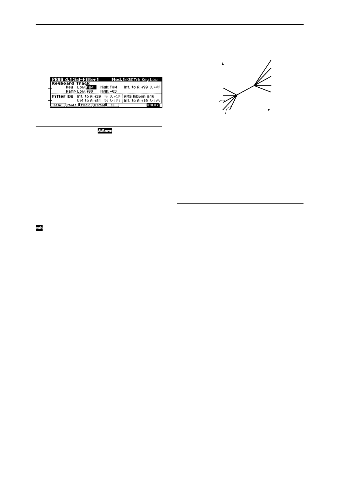
4.1–2: Mod.1 (Filter1 Modulation1)
Indicates settings for keyboard tracking which modifies the
tone by modulating the filter 1 cutoff frequency “Frequency
(A/B Frequency),” and intensity settings for the filter 1 EG,
etc.
4.1–2a
4.1–2b
4.1–2c
4.1–2a: Keyboard Track
These settings specify keyboard tracking for the cutoff frequency of filter 1. The way in which the cutoff frequency is
affected by the keyboard location you play can be specified
by the Key: “Low” and “High,” Ramp: “Low” and “High”
parameters.
Key:
Specifies the note numbers at which keyboard tracking will
begin to apply, and set the “Int. to A” and “(Int. to) B”
parameters to specify the depth and direction of the change
applied to filter 1 A and B.
For the range of notes between “Low (KBDTrk Key Low)”
and “High (KBDTrk Key High),” the cutoff frequency will
change according to the keyboard location (pitch).
You can also input a value by playing a note on the keyboard while you hold down the [ENTER] key.
Low (KBDTrk Key Low) [C–1…G9]
Keyboard tracking will apply to the range below the specified note number.
High (KBDTrk Key High) [C–1…G9]
Keyboard tracking will apply to the range above the specified note number.
Ramp (Ramp Setting):
Specifies the angle of keyboard tracking.
Low (KBDTrk Ramp Low) [–99…+99]
High (KBDTrk Ramp High) [–99…+99]
If “Int. to A (KBDTrk Int. to A)” and “Int. to B (KBDTrk Int.
to B)” are set to +50, “Low (KBDTrk Ramp Low)” is set to
–62 and “High (KBDTrk Ramp High)” is set to +62, the angle
of the change in cutoff frequency will correspond to the keyboard location (pitch). This means that the oscillation that
occurs when you increase the “Resonance (A Resonance)”
(4.1–1b) will correspond to the keyboard location.
If you set “Low (KBDTrk Ramp Low)” to +43 and “High
(KBDTrk Ramp High)” to –43, the cutoff frequency will not
be affected by keyboard location. Use this setting when you
do not want the cutoff frequency to change for each note.
4.1–2d
How cutoff frequency is affected by keyboard location and the Ramp
setting
(“Int. to A,” “Int. to B”=+50)
Cutoff frequency
Low Ramp=+99
Low Ramp=+43
Low Ramp=0
Low Ramp=–62
Low Ramp=–99
Low Key
High Key
High Ramp=+99
High Ramp=+62
High Ramp=0
High Ramp=–43
High Ramp=–99
Key
Int. to A (KBDTrk Int. to A) [–99...+99]
Specifies the depth and direction of the effect on filter 1A
produced by keyboard tracking settings “Low (KBDTrk Key
Low),” “High (KBDTrk Key High),” “Low (KBDTrk Ramp
Low),” and “High (KBDTrk Ramp High).”
With positive (+) settings, the effect will be in the same direc-
tion as the keyboard tracking settings. With negative (–) settings, the effect will be in the opposite direction.
Int. to B (KBDTrk Int. to B) [–99...+99]
Specifies the depth and direction of the effect on filter 1B
produced by keyboard tracking. (
☞“Int. to A”)
4.1–2b: Filter EG
Int. to A (Intensity to A) [–99…+99]
Specifies the depth and direction of the effect that the timevarying changes created by the filter 1 EG will have on the
filter 1A cutoff frequency.
With positive (+) settings, the sound will become brighter
when the EG levels set by Filter 1 EG “L (Level)” and “T
(Time)” parameters (4.1–5a) are in the “+” area, and darker
when they are in the “–” area.
With negative (–) settings, the sound will become darker
when the EG levels set by Filter 1 EG “L (Level)” and “T
(Time)” parameters are in the “+” area, and brighter when
they are in the “–” area.
Int. to B (Intensity to B) [–99…+99]
Specifies the depth and direction of the effect that the timevarying changes created by the filter 1 EG will have on the
filter 1B cutoff frequency.
☞ (“Int. to A” Intensity to A)
Vel to A (Velocity to A) [–99…+99]
This parameter specifies the depth and direction of the effect
that velocity will have on the time-varying changes created
by the filter 1 EG (as set by “Filter 1 EG” 4.1–5) to control the
filter 1A cutoff frequency.
With positive (+) values, playing more strongly will cause
the filter 1 EG to produce greater changes in cutoff frequency. With negative (–) values, playing more strongly will
also cause the filter 1 EG to produce greater changes in cutoff frequency, but with the polarity of the EG inverted.
16
Vel to B (Velocity to B) [–99…+99]
This parameter specifies the depth and direction of the effect
that velocity will have on the time-varying changes created
by the filter 1 EG to control the filter 1B cutoff frequency.
☞ (“Vel to A” Velocity to A).
Page 27
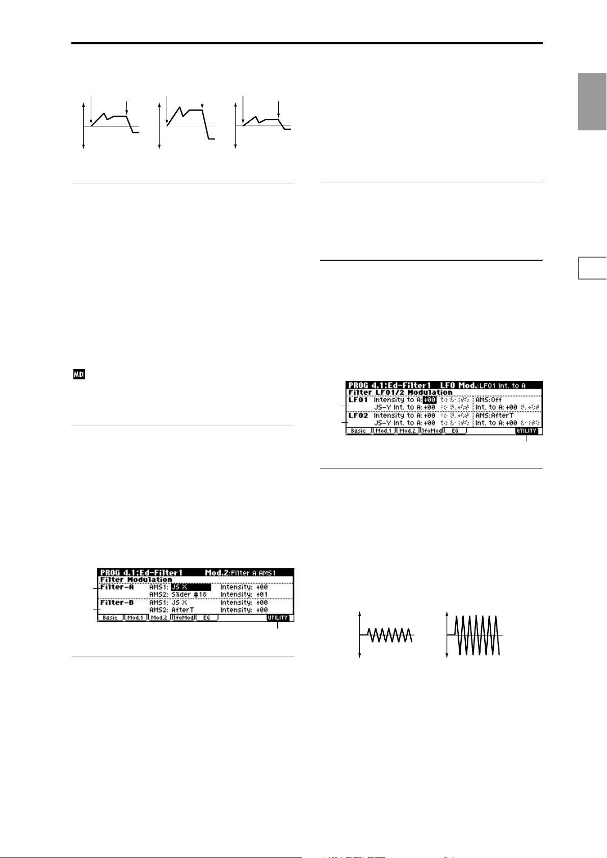
Changes in cutoff frequency
Note-on
Softly played
(The setting of Intensity to A (4.1–2b))
Note-off
Note-on
Strongly played
Setting to +
Note-off
Note-on
Strongly played
Setting to –
Note-off
value for this parameter, the opposite will occur.
This value is added to the setting of the Filter A “Frequency
(A Frequency)”(4.1–1b).
AMS2 (Filter A AMS2) [Off, (PEG, AEG, EXT)]
Intensity (A AMS2 Intensity) [–99…+99]
Selects “AMS2 (Filter A AMS2),” and specify the depth and
direction of the effect that the selected source will have
(
☞“AMS1,” “Intensity”).
PROG
1.1
■ 4.1–2c: AMS, Into to A, Int to B
AMS (Filter EG AMS) [Off, (EXT)]
Indicates the source that will control the depth and direction
of the effect that the time-varying changes produced by the
filter 1 EG will have on the cutoff frequency of filters 1A and
1B (
☞p.222 “AMS List”).
Int. to A (AMS Int. to A) [–99…+99]
Specifies the depth and direction of the effect that “AMS
(Filter EG AMS)” will have on filter 1A. For details on how
this will apply, refer to “Int. to A (Intensity to A).”
Int. to B (AMS Int. to B) [–99…+99]
Specifies the depth and direction of the effect that “AMS
(Filter EG AMS)” will have on filter 1B. For details on how
this will apply, refer to “Int. to A (Intensity to A).”
The sum of the settings for “Int. to A (B),” “Vel to A
(B),” and “Int. to A (B) (AMS Int. to A/B)” will determine the depth and direction of the effect produced by
the filter EG.
■ 4.1–2d: UTILITY
☞ “Write Program” (1.1–1c), “Copy Oscillator,” “Swap
Oscillator” (2.1–1d)
■ 4.1–3b: Filter-B Modulation
This will be displayed when “Type (Filter Type)” (4.1–1a) is
Low Pass & High Pass.
Two alternate modulation sources can be used to modulate
the cutoff frequency of filter 1B (
■ 4.1–3c: UTILITY
☞ “Write Program” (1.1–1c), “Copy Oscillator,” “Swap
☞“Filter-A Modulation”).
Oscillator” (2.1–1d)
4.1–4: lfoMod (LFO Modulation)
Here you can use the filter 1 LFO to apply cyclic modulation
to the cutoff frequency of filter 1 (for oscillator 1) to create
cyclical changes in tone.
4.1–4a
4.1–4b
4.1–4c
4.1–4a: Filter LFO1 Modulation
2.12.22.33.14.14.25.15.25.36.16.26.36.47.17.27.3
4.1–3: Mod.2 (Filter1 Modulation2)
Indicates settings for the controller that will modify the tone
by applying modulation to the filter 1 cutoff frequency “Frequency (A/B Frequency).”
If “Type (Filter Type)” (4.1–1a) is Low Pass Resonance, the
filter B parameters will not be displayed.
4.1–3a
4.1–3b
4.1–3b
4.1–3a: Filter-A Modulation
AMS1 (Filter A AMS1) [Off, (PEG, AEG, EXT)]
Indicates the source that will control modulation of the filter
1A cutoff frequency (
Intensity (A AMS1 Intensity) [–99…+99]
Specifies the depth and direction of the effect that “AMS1
(Filter A AMS1)” will have.
When “AMS1 (Filter A AMS1)” is JS X, a positive (+) value
for this parameter will cause the cutoff frequency to rise
when the joystick is moved toward the right, and fall when
the joystick is moved toward the left. With a negative (–)
☞p.222 “AMS List”).
Intensity to A (LFO1 Int. to A) [–99…+99]
Specifies the depth and direction of the modulation that
OSC1 LFO1 (set by “OSC1 LFO1” 5.3–1a) will have on the
cutoff frequency of filter 1A.
Negative (–) settings will invert the phase.
Intensity to B (LFO1 Int. to B) [–99…+99]
Specifies the depth and direction of the modulation that
OSC1 LFO1 will have on the cutoff frequency of filter 1B
(
☞“Intensity to A”).
Change in cutoff
Low setting High setting
JS–Y Int. to A (LFO1 JS–Y Int. to A) [–99…+99]
By moving the joystick in the Y direction (toward yourself),
you can control the depth at which OSC1 LFO1 modulates
the cutoff frequency of filter 1A. This parameter specifies the
depth and direction of the control.
For example, as this value is raised, OSC1 LFO1 will have a
correspondingly greater effect on filter 1 when the joystick is
moved in the –Y direction.
17
Page 28
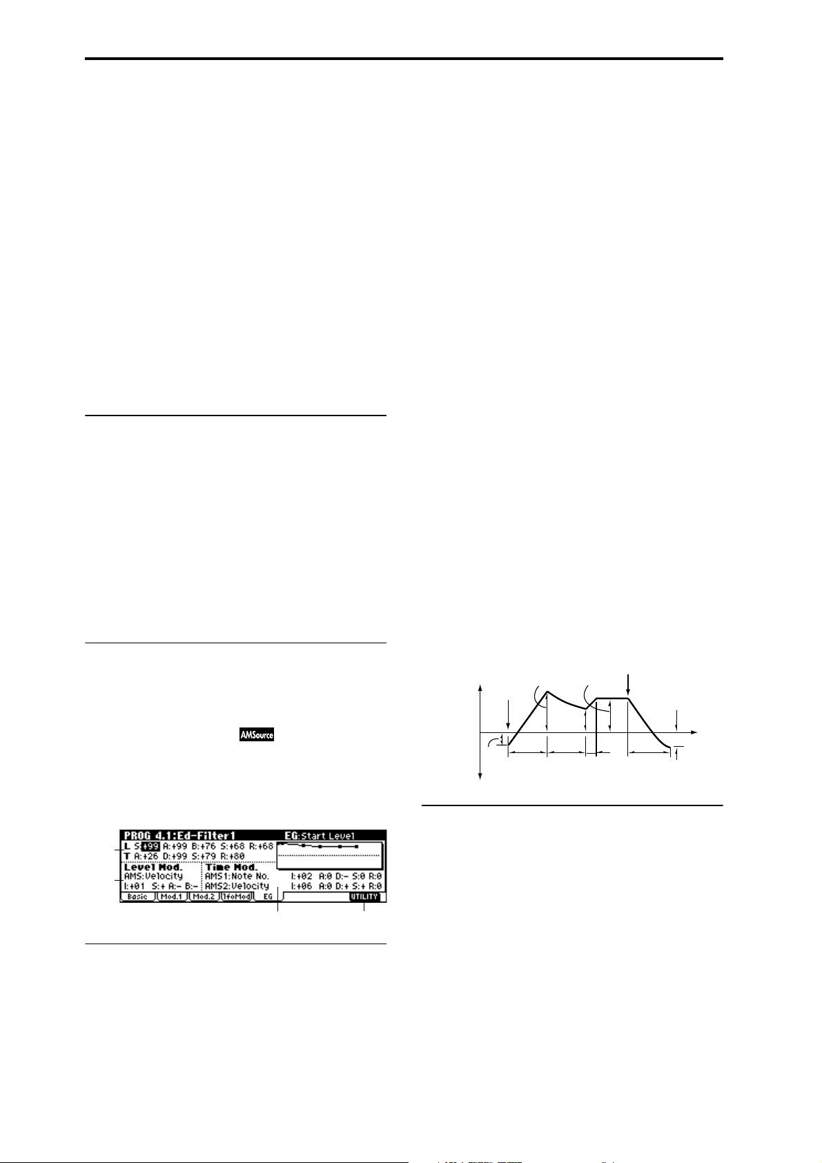
JS–Y Int. to B (LFO1 JS–Y Int. to B) [–99…+99]
By moving the joystick in the Y direction (toward yourself),
you can control the depth at which OSC1 LFO1 modulates
the cutoff frequency of filter 1B. This parameter specifies the
depth and direction of the control. (
☞“JS –Y Int. to A”)
AMS (LFO1 AMS) [Off, (PEG, FEG, AEG, KT, EXT)]
Selects a source that will control the depth and direction of
cutoff frequency change for both filters 1A and 1B (
☞p.222
“AMS List”).
Int. to A (LFO1 AMS Int. to A) [–99…+99]
Specifies the depth and direction of the effect that “AMS
(LFO1 AMS)” will have on filter 1A.
For example, if “AMS” is AfterT, higher settings of this
parameter will allow greater change to be applied to OSC1
LFO1 when you apply pressure to the keyboard.
Int. to B (LFO1 AMS Int. to B) [–99…+99]
Specifies the depth and direction of the effect that “AMS
(LFO1 AMS)” will have on filter 1B (
☞“Int. to A”).
4.1–4b: Filter LFO2 Modulation
Adjusts the depth of the cyclic modulation applied by OSC1
LFO2 (set by “OSC1 LFO 2” 5.3–2) to the cutoff frequency of
filters 1A and 1B (
☞“Filter LFO 1 Modulation” 4.1–4a).
Intensity to A (LFO2 Int. to A) [–99…+99]
Intensity to B (LFO2 Int. to B) [–99…+99]
JS–Y Int. to A (LFO2 JS–Y Int. to A) [–99…+99]
JS–Y Int. to B (LFO2 JS–Y Int. to B) [–99…+99]
AMS (LFO2 AMS) [Off, (PEG, FEG, AEG, KT, EXT)]
Int. to A (LFO2 AMS Int. to A) [–99…+99]
Int. to B (LFO2 AMS Int. to B) [–99…+99]
■ 4.1–4c: UTILITY
☞ “Write Program” (1.1–1c), “Copy Oscillator,” “Swap
Oscillator” (2.1–1d)
4.1–5: EG (Filter1 EG)
Here you can make settings for the EG that will produce
time-varying changes in the cutoff frequency of filters 1A
and 1B.
The depth of the effect that these settings will have on the filter 1 cutoff frequency is determined by “Filter EG” (4.1–2b).
S (Start Level) [–99…+99]
Specifies the change in cutoff frequency at the time of noteon.
A (Attack Level) [–99…+99]
Specifies the change in cutoff frequency after the attack time
has elapsed.
B (Break Point Level) [–99…+99]
Specifies the change in cutoff frequency after the decay time
has elapsed.
S (Sustain Level) [–99…+99]
Specifies the change in cutoff frequency that will be maintained from after the slope time has elapsed until note-off
occurs.
R (Release Level) [–99…+99]
Specifies the change in cutoff frequency that will occur when
the release time has elapsed.
T (Time):
These parameters specify the time over which each change
will occur.
A (Attack Time) [00…99]
Specifies the time over which the level will change from
note-on until the attack level is reached.
D (Decay Time) [00…99]
Specifies the time over which the level will change from the
attack level to the break point level.
S (Slope Time) [00…99]
Specifies the time over which the level will change after the
decay time has elapsed until the sustain level is reached.
R (Release Time) [00…99]
Specifies the time over which the level will change after
note-on occurs until the release level is reached.
Note-off
Break
Point
Level
Decay
Time
Sustain Level
Slope
Time
Release
Time
Release
Level
Time
The specified
cutoff
frequency
Start
Level
Note-on
Attack Level
Attack
Time
4.1–5b: Level Mod. (Level Modulation)
4.1–5a
4.1–5b
4.1–5c
4.1–5a: Filter1 EG
Specifies the time-varying change produced by the filter 1 EG.
L (Level):
The result will depend on the filter that was selected in
“Type (Filter Type)” (4.1–1a). For example with the Low
Pass Resonance filter, positive (+) values of “Int. to A” (4.1–
2b) will cause the tone to be brightened by positive (+) lev-
els, and darkened by negative (–) levels.
18
4.1–5d
These settings let you use alternate modulation to control
the “L (Level)” parameters of the filter 1 EG.
AMS (Level Mod. AMS) [Off, (KT, EXT)]
Indicates the source that will control the “L (Level)” parameters of the filter 1 EG (
☞p.222 “AMS List”).
I (AMS Intensity) [–99…+99]
Specifies the depth and direction of the effect that “AMS
(Level Mod. AMS)” will have.
For example, if “AMS (Level Mod. AMS)” is Velocity, and
you set “S (AMS SW Start),” “A (AMS SW Attack)” and “B
(AMS SW Break)” to + and set “I (AMS Intensity)” to a posi-
tive (+) value, the EG levels will rise as you play more
strongly. If “Intensity” is set to a negative (–) values, the EG
levels will fall as you play more strongly.
With a setting of 0, the levels specified by “Filter 1 EG” (4.1–
5a) will be used.
Page 29
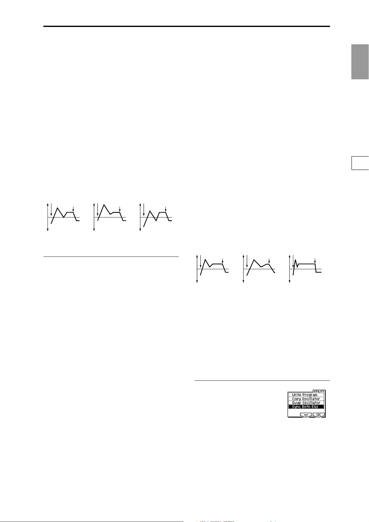
S (AMS SW Start) [–, 0, +]
Specifies the direction in which “AMS (Level Mod. AMS)”
will affect “S (Start Level).” When “I (AMS Intensity)” has a
positive (+) value, a setting of + for this parameter will
allow “AMS” to raise the EG level, and a setting of – will
allow “AMS” to lower the EG level. With a setting of 0 there
will be no change.
A (AMS SW Attack) [–, 0, +]
Specifies the direction in which “AMS (Level Mod. AMS)”
will affect “A(Attack Level).” When “I (AMS Intensity)” has
a positive (+) value, a setting of + for this parameter will
allow “AMS” to raise the EG level, and a setting of – will
allow “AMS” to lower the EG level. With a setting of 0 there
will be no change.
A (AMS1 SW Attack) [–, 0, +]
Specifies the direction in which “AMS1 (Time Mod. AMS1)”
will affect the attack time. With positive (+) values of “I
(AMS1 Intensity),” setting this parameter to + will allow
AMS1 to lengthen the time, and setting this parameter to –
will allow AMS1 to shorten the time. With a setting of 0
there will be no change.
D (AMS1 SW Decay) [–, 0, +]
Specifies the direction in which “AMS1 (Time Mod. AMS1)”
will affect the decay time. With positive (+) values of “I
(AMS1 Intensity),” setting this parameter to + will allow
AMS1 to lengthen the time, and setting this parameter to –
will allow AMS1 to shorten the time. With a setting of 0
there will be no change.
PROG
1.1
2.12.22.33.14.14.25.15.25.36.16.26.36.47.17.27.3
B (AMS SW Break) [–, 0, +]
Specifies the direction in which “AMS (Level Mod. AMS)”
will affect “B (Break Point Level).” When “I (AMS Intensity)” has a positive (+) value, a setting of + for this parameter will allow “AMS” to raise the EG level, and a setting of –
will allow “AMS” to lower the EG level. With a setting of 0
there will be no change.
Filter 1 EG changes (level) (AMS = Velocity, Intensity = a positive (+) value)
Note-on
Softly played note with “S,”
“A,” and “B” set to + (setting
of 4.1–5a: Filter 1 EG)
Note-off
Note-on
Strongly played note with
“S,” “A,” and “B” set to +
Note-off
Note-on
Strongly played note with
“S,” “A,” and “B” set to –
Note-off
4.1–5c: Time Mod. (Time Modulation)
These settings let you use alternate modulation to control
the “T (Time)” parameters of the filter 1 EG.
AMS1 (Time Mod. AMS1) [Off, (KT, EXT)]
Indicates the source that will control the “T (Time)” parameters of the filter 1 EG (
☞p.222 “AMS List”).
I (AMS1 Intensity) [–99…+99]
Specifies the depth and direction of the effect that “AMS1
(Time Mod. AMS1)” will have.
For example, if “AMS1 (Time Mod. AMS1)” is set to Flt KTr
+/+, the EG “T (Time)” parameters will be controlled by the
Keyboard Track (4.1–2a) settings. With positive (+) values of
this parameter, positive (+) values of “Ramp (Ramp Setting)” (4.1–2a) will lengthen the EG times, and negative (–)
values of “Ramp (Ramp Setting)” will shorten the EG times.
The direction of change is specified by “A (AMS1 SW
Attack),” “D (AMS1 SW Decay),” “S (AMS1 SW Slope),” and
“R (AMS1 SW Release).”
With a setting of 0, the times specified by “Filter1 EG” (4.1–
5a) will be used.
If “AMS1 (Time Mod. AMS1)” is set to Velocity, positive (+)
values of this parameter will cause EG times to lengthen as
you play more strongly, and negative (–) values will cause
EG times to shorten as you play more strongly.
With a setting of 0, the times specified by “Filter1 EG” will
be used.
S (AMS1 SW Slope) [–, 0, +]
Specifies the direction in which “AMS1 (Time Mod. AMS1)”
will affect the slope time. With positive (+) values of “I
(AMS1 Intensity),” setting this parameter to + will allow
AMS1 to lengthen the time, and setting this parameter to –
will allow AMS1 to shorten the time. With a setting of 0
there will be no change.
R (AMS1 SW Release) [–, 0, +]
Specifies the direction in which “AMS1 (Time Mod. AMS1)”
will affect the release time. With positive (+) values of “I
(AMS1 Intensity),” setting this parameter to + will allow
AMS1 to lengthen the time, and setting this parameter to –
will allow AMS1 to shorten the time. With a setting of 0
there will be no change.
Filter 1 EG changes (Time) (AMS = Velocity, Intensity = a positive (+) value)
Note-on
Softly played note with “A,”
“D,” “S” and “R” set to +
(setting of 4.1–5a: Filter 1 EG)
Note-off
Note-on
Strongly played note with
“A,” “D,” “S” and “R” set to +
Note-off
Note-on
Strongly played note with
“A,” “D,” “S” and “R” set to –
Note-off
AMS2 (Time Mod. AMS2) [Off, (KT, EXT)]
I (AMS2 Intensity) [–99…+99]
A (AMS2 SW Attack) [–, 0, +]
D (AMS2 SW Decay) [–, 0, +]
S (AMS2 SW Slope) [–, 0, +]
R (AMS2 SW Release) [–, 0, +]
These parameters are the settings for “AMS2” to control the
“Time” parameters of the filter 1 EG (
AMS1)”–“R (AMS1 SW Release)”).
■ 4.1–5d: UTILITY
☞ “Write Program” (1.1–1c), “Copy Oscillator,” “Swap
Oscillator” (2.1–1d)
For details on how to select the desired utility function, refer
to “PROG 1.1–1c: UTILITY.”
☞“AMS1 (Time Moc.
19
Page 30
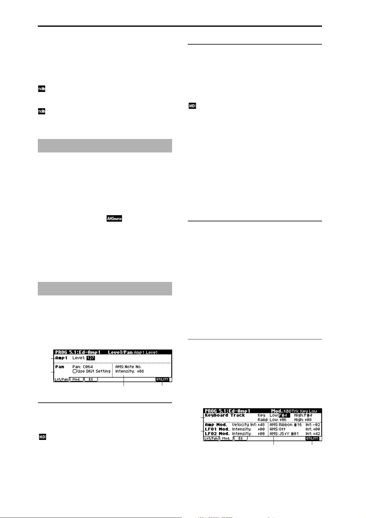
Sync Both EGs
If you select “Sync Both EGs” from the Utility menu and
press the [F8] key, a check mark will appear at the left of
“Sync Both EGs.” In this state, the filter 1 EG and the filter 2
EG can be edited simultaneously. (Editing either one will
cause the other to change.)
“Sync Both EGs” cannot sync the filter EG and amp EG
independently. For example if you sync in 5.1–3d, it will
be synced here as well.
This can be selected only if “Mode (Oscillator Mode)”
(2.1–1a) is Double.
PROG 4.2: Ed–Filter2
4.2–1: Basic
4.2–2: Mod.1
(Filter2 Modulation1)
4.2–3: Mod.2 (Filter2 Modulation2)
4.2–4: lfoMod (LFO Modulation)
4.2–5: EG (Filter2 EG)
Indicates settings for filter 2, which controls the tone of oscillator 2. You can select either a 24 dB/oct low pass filter with
resonance, or a 12 dB/oct low pass filter and 12 dB/oct high
pass filter connected in series. Filter 2 can be used when
“Mode (Oscillator Mode)” (2.1–1a) is Double. (
Ed-Filter 1")
☞“PROG 4.1:
PROG 5.1: Ed–Amp1
Indicates settings for amp 1 which controls the volume of
oscillator 1. Pan settings are also made here.
5.1–1: Lvl/Pan (Level/Pan)
These parameters control the volume and pan of oscillator 1.
5.1–1b: Pan
Pan (Amp1 Pan) [Random, L001…C064…R127]
Sets the pan (stereo location) of oscillator 1.
A setting of L001 places the sound at far left, C064 in the
center, and R127 to far right.
Random: The sound will be heard from a different location
at each note-on.
This can be controlled by CC#10 (panpot). A CC#10
value of 0 or 1 will place the sound at the far left, a
value of 64 will place the sound at the location specified
by the “Pan” setting for each oscillator, and a value of
127 will place the sound at the far right. This is controlled on the global MIDI channel “MIDI Channel”
(GLOBAL 2.1–1a).
Use DKit Setting [Off, On]
This is valid when “Mode (Oscillator Mode)” (2.1–1a) is set
to Drums.
On (checked): The sound will be output at the “Pan” setting that has been made for each key of the drum kit (GLOBAL 5.1–3a). When “Mode (Oscillator Mode)” is Drums,
you will normally use this setting.
Off (unchecked): All notes will be output as specified by the
“Pan (Amp1 Pan)” setting.
5.1–1c: AMS, Intensity
AMS (Pan AMS) [Off, (PEG, FEG, AEG, LFO, KT, EXT)]
Indicates the source that will modify pan (☞p.222 “AMS
List”). This change will be relative to the “Pan (Amp1 Pan)”
setting.
Intensity [–99…+99]
Specifies the depth of the effect produced by “AMS (Pan
AMS).”
For example, if “Pan (Amp1 Pan)” is set to C064 and “AMS
(Pan AMS)” is Note Number, positive (+) values of this
parameter will cause the sound to move toward the right as
the note numbers increase beyond the C4 note (i.e., as you
play higher), and toward the left as the note numbers
decrease (i.e., as you play lower). Negative (–) values of this
parameter will have the opposite effect.
■ 5.1–1d: UTILITY
5.1–1a
5.1–1b
5.1–1c
5.1–1a: Amp1 Level
Level (Amp1 Level) [0…127]
Sets the volume of oscillator 1.
The volume of a program can be controlled by CC#7
(volume) and CC#11 (expression). The resulting level is
determined by multiplying the values of CC#7 and
CC#11. The Global MIDI channel “MIDI Channel”
(GLOBAL 2.1–1a) is used for control.
20
5.1–1d
☞ “Write Program” (1.1–1c), “Copy Oscillator,” “Swap
Oscillator” (2.1–1d)
5.1–2: Mod. (Amp1 Modulation)
These settings allow you to apply modulation to amp 1 (for
oscillator 1) to modulate the volume.
5.1–2a
5.1–2b
5.1–2c
5.1–2d
Page 31

5.1–2a: Keyboard Track
These parameters let you use keyboard tracking to adjust
the volume of oscillator 1. Use the “Key” and “Ramp”
parameters to specify how the volume will be affected by
the keyboard location that you play.
LFO1 Mod. (LFO1 Modulation):
Intensity (LFO1 Intensity) [–99…+99]
These parameters let you use “OSC1 LFO1” (5.3–1) to control the oscillator 1 volume.
Negative (–) values will invert the LFO waveform.
PROG
Key (Keyboard Track Key):
Specifies the note number at which keyboard tracking will
begin to apply.
The volume will not change between “Low (KBDTrk Key
Low)” and “High (KBDTrk Key High).”
You can also input a value by playing a note on the keyboard while you hold down the [ENTER] key.
Low (KBDTrk Key Low) [C–1…G9]
Keyboard tracking will apply to the range of notes below the
note number you specify here.
High (KBDTrk Key High) [C–1…G9]
Keyboard tracking will apply to the range of notes above the
note number you specify here.
Ramp (Ramp Setting):
Specifies the angle of the keyboard tracking.
Low (KBDTrk Ramp Low) [–99…+99]
With positive (+) values of this parameter, the volume will
increase as you play notes below the “Low (KBDTrk Key
Low)” note number. With negative (–) values, the volume
will decrease.
High (KBDTrk Ramp High) [–99…+99]
With positive (+) values of this parameter, the volume will
increase as you play notes above the “High (KBDTrk Key
High)” note number. With negative (–) values, the volume
will decrease.
Volume change produced by keyboard location and Ramp settings
Volume
LFO2 Mod. (LFO2 Modulation):
Intensity (LFO2 Intensity) [–99…+99]
Specifies the depth and direction of the effect that “OSC1
LFO2”(5.3–2) will have on the volume of oscillator 1. Refer
to the preceding sections “LFO1 Mod. (LFO1 Modulation).”
5.1–2c: AMS, Int.
AMS (Amp AMS) [Off, (PEG, FEG, EXT)]
Indicates the source that will control the volume of amp 1
(
☞p.222 “AMS List”) (EXT) Velocity cannot be selected.
Int. (AMS Intensity) [–99…+99]
Specifies the depth and direction of the effect that “AMS
(Amp AMS)” will have.
The actual volume will be determined by multiplying the
value of the changes produced by the amp EG with the values of Alternate Modulation etc., and if the levels of the amp
EG are low, the modulation applied by Alternate Modulation will also be less.
For example, if you set “AMS (Amp AMS)” to AfterT and
press down on the keyboard, the volume will increase if you
have set this parameter to a positive (+) value. However if
the volume is already at maximum due to the EG settings
etc., it will not be possible to increase the volume any further. If you have set this parameter to a negative (–) value,
pressing down on the keyboard will decrease the volume.
AMS (LFO1 AMS) [Off, (PEG, FEG, AEG, KT, EXT)]
Indicates a source that will control the depth by which
“OSC1 LFO1” will modulate the volume of oscillator 1
(
☞p.222 “AMS List”).
1.1
2.12.22.33.14.14.25.15.25.36.16.26.36.47.17.27.3
Ramp Low=+99
Ramp Low=0
Ramp Low=–99
KBDTrk Low KBDTrk High
Ramp High=+99
Ramp High=0
Ramp High=–99
Key
5.1–2b: Amp Mod., LFO1 Mod., LFO2 Mod.
Indicates settings to specify how the volume of oscillator 1
will be controlled by velocity, OSC1 LFO1, and OSC1 LFO2.
Amp Mod. (Amp Modulation):
Velocity Int. (Amp Velocity Int.) [–99…+99]
With positive (+) values, the volume will increase as you
play more strongly.
With negative (–) values, the volume will decrease as you
play more strongly.
Volume change (with positive (+) values of this parameter)
Note-on
Softly played
Note-off
Note-on
Strongly played
Note-off
Int. (AMS Intensity) [–99…+99]
Specifies the depth and direction of the effect that “OSC1
LFO1” will have on the volume of oscillator 1. Negative (–)
values will invert the LFO waveform.
AMS (LFO2 AMS) [Off, (PEG, FEG, AEG, KT, EXT)]
Indicates a source that will control the depth by which
“OSC1 LFO2” will modulate the volume of oscillator 1
(
☞p.222 “AMS List”).
Int. (AMS Intensity) [–99…+99]
Specifies the depth and direction of the effect that “OSC1
LFO2” will have on the volume of oscillator 1. Negative (–)
values will invert the LFO waveform.
■ 5.1–2d: UTILITY
☞ “Write Program” (1.1–1c), “Copy Oscillator,” “Swap
Oscillator” (2.1–1d)
21
Page 32
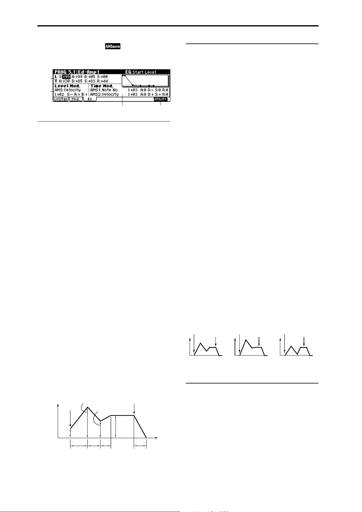
5.1–3: EG (Amp1 EG)
Indicates settings to specify how Amp 1 will cause the volume of oscillator 1 to change over time.
5.1–3b: Level Mod. (Level Modulation)
These parameters let you use AMS to control the amp 1 EG
levels that were specified in “Amp 1 EG” (5.1–3a).
5.1–3a
5.1–3b
5.1–3c
5.1–3d
5.1–3a: Amp1 EG
These parameters specify how the amp 1 EG will change
over time.
L (Level):
S (Start Level) [00…99]
Specifies the volume level at note-on.
If you want the note to begin at a loud level, set this to a high
value.
A (Attack Level) [00…99]
Specifies the volume level that will be reached after the
attack time has elapsed.
B (Break Point Level) [00…99]
Specifies the volume level that will be reached after the
decay time has elapsed.
S (Sustain Level) [00…99]
Specifies the volume level that will be maintained from after
the slope time has elapsed until note-off occurs.
Time:
A (Attack Time) [00…99]
Specifies the time over which the volume will change after
note-on until it reaches the attack level.
If the start level is 0, this will be the rise time of the sound.
D (Decay Time) [00…99]
Specifies the time over which the volume will change from
when it reaches the attack level until it reaches the break
point level.
S (Slope Time) [00…99]
Specifies the time over which the volume will change from
when it reaches the break point level until it reaches the sustain level.
R (Release Time) [00…99]
Specifies the time over which the volume will change after
note-off until it reaches 0.
Volume
Amplifier EG
Note-on
Attack Level
Start
Level
Break Point
Sustain
Level
Note-off
Time
AMS (Level Mod. AMS) [Off, (KT, EXT)]
Selects the source that will control the “Level” parameters of
the amp 1 EG (
☞p.222 “AMS List”).
I (AMS Intensity) [–99…+99]
Specifies the depth and direction of the effect that “AMS
(Level Mod. AMS)” will have.
For example, if “AMS (Level Mod. AMS)” is Velocity, setting
“S (AMS SW Start),” “A (AMS SW Attack),” and “B (AMS
SW Break)” to + and setting “Intensity” to a positive (+)
value will cause the amp 1 EG volume levels to increase as
you play more strongly. Setting “Intensity” to a negative (–)
values will cause the amp 1 EG volume levels to decrease as
you play more strongly. With a setting of 0, the levels will be
as specified in “Amp 1 EG” (5.1–3a).
S (AMS SW Start) [–, 0, +]
Specifies the direction in which “AMS (Level Mod. AMS)”
will change “S (Start Level).” If “I (AMS Intensity)” is set to
a positive (+) value, setting this parameter to + will allow
AMS to increase the EG level, and setting this parameter to –
will allow AMS to decrease the EG level. With a setting of 0,
no change will occur.
A (AMS SW Attack) [–, 0, +]
Specifies the direction in which “AMS (Level Mod. AMS)”
will change “A (Attack Level).” If “I (AMS Intensity)” is set
to a positive (+) value, setting this parameter to + will allow
AMS to increase the EG level, and setting this parameter to –
will allow AMS to decrease the EG level. With a setting of 0,
no change will occur.
B (AMS SW Break) [–, 0, +]
Specifies the direction in which “AMS (Level Mod. AMS)”
will change “B (Break Point Level).” If “I (AMS Intensity)” is
set to a positive (+) value, setting this parameter to + will
allow AMS to increase the EG level, and setting this parameter to – will allow AMS to decrease the EG level. With a setting of 0, no change will occur.
Amp 1 EG changes (Level) (AMS=Velocity, Intensity = a positive (+) value)
Note-on
Note-off
Softly played note when “S”=0
and “A” and “B” are set to +
(settings of 5.1–3a: Amp 1 EG)
Note-on
Strongly played note
when “S”=0 and “A” and
“B” are set to +
Note-off
Note-on
Note-off
Strongly played note
when “S”=0 and “A” and
“B” are set to –
5.1–3c: Time Mod. (Time Modulation)
You can use two AMS sources to control the Amp 1 EG times
that were specified in “Amp 1 EG” (5.1–3a).
AMS1 (Time Mod. AMS1) [Off, (EXT, KT)]
Selects the source that will control the “Time ” parameters of
Amp 1 EG. (
☞p.222 “AMS List”)
22
Attack
Time
Decay
Time
Slope
Time
Release Time
Page 33
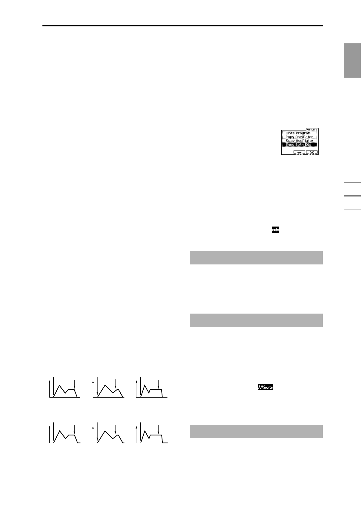
I (AMS1 Intensity) [–99…+99]
Specifies the depth and direction of the effect that “AMS1
(Time Mod. AMS1)” will have.
For example, if “AMS1 (Time Mod. AMS1)” is Amp KT +/+,
the (Amp) “Keyboard Track” settings (5.1–2a) will control
the EG “Time” parameters. With positive (+) values of this
parameter, positive (+) values of “Ramp (Ramp Setting)”
will cause EG times to be lengthened, and negative (–) val-
ues of “Ramp (Ramp Setting)” will cause EG times to be
shortened. The direction of the change is specified by “A
(AMS1 SW Attack),” “D (AMS1 SW Decay),” “S (AMS1 SW
Slope),” and “R (AMS1 SW Release).”
When “AMS1 (Time Mod. AMS1)” is Velocity, positive (+)
values will cause EG times to lengthen as you play more
strongly, and negative (–) values will cause EG times to
shorten as you play more strongly. With a setting of 0, the EG
times will be as specified in “Amp1 EG” (5.1–3a).
A (AMS1 SW Attack) [–, 0, +]
Specifies the direction of the effect that “AMS1 (Time Mod.
AMS1)” will have on “A (Attack Time).” With positive (+)
values of “I (AMS1 Intensity),” setting this parameter to +
will allow AMS1 to lengthen the time, and setting it to – will
allow AMS1 to shorten the time. With a setting of 0 there
will be no effect.
D (AMS1 SW Decay) [–, 0, +]
Specifies the direction of the effect that “AMS1 (Time Mod.
AMS1)” will have on “D (Decay Time).” With positive (+)
values of “I (AMS1 Intensity),” setting this parameter to +
will allow AMS1 to lengthen the time, and setting it to – will
allow AMS1 to shorten the time. With a setting of 0 there
will be no effect.
AMS2 (Time Mod. AMS2) [Off, (EXT, KT)]
I (AMS2 Intensity) [–99…+99]
A (AMS2 SW Attack) [–, 0, +]
D (AMS2 SW Decay) [–, 0, +]
S (AMS2 SW Slope) [–, 0, +]
R (AMS2 SW Release) [–, 0, +]
These parameters specify how “AMS2 (Time Mod. AMS2)”
will control the amp 1 EG “Time” parameters (
☞“AMS1
(Time Mod. AMS1)”–“R(AMS1 SW Release)”).
■ 5.1–3d: UTILITY
☞ “Write Program” (1.1–1c), “Copy Oscillator,” “Swap
Oscillator” (2.1–1d)
For details on how to select the desired utility function, refer
to “PROG 1.1–1c: UTILITY.”
Sync Both EGs
If you select “Sync Both EGs” from the Utility menu and
press the [F8] key, a check mark will appear at the left of
“Sync Both EGs.” In this state, the amp 1 EG and the amp 2
EG can be edited simultaneously. (Editing either one will
cause the other to change.) (
☞4.1–5d )
PROG
1.1
2.12.22.33.14.14.25.15.25.36.16.26.36.47.17.27.3
S (AMS1 SW Slope) [–, 0, +]
Specifies the direction of the effect that “AMS1 (Time Mod.
AMS1)” will have on “S (Slope Time).” With positive (+)
values of “I (AMS1 Intensity),” setting this parameter to +
will allow AMS1 to lengthen the time, and setting it to – will
allow AMS1 to shorten the time. With a setting of 0 there
will be no effect.
R (AMS1 SW Release) [–, 0, +]
Specifies the direction of the effect that “AMS1 (Time Mod.
AMS1)” will have on “R (Release Time).” With positive (+)
values of “I (AMS1 Intensity),” setting this parameter to +
will allow AMS1 to lengthen the time, and setting it to – will
allow AMS1 to shorten the time. With a setting of 0 there
will be no effect.
Amp 1 EG changes (Time)
(AMS=Amp KTrk +/+, Intensity = a positive (+) value)
(When Amp Keyboard Track (5.1–2a) Low Ramp= a positive (+) value, and
High Ramp = a positive (+) value)
Note-on
Settings of 5.1–3a: Amp 1
EG
Amp 1 EG changes (Time) (AMS=Velocity, Intensity= a positive (+) value)
Note-on
Note-off
Note-off
Note-on
Low-pitched note played
with “A,” “D,” “S”, and “R”
at +
Note-on
Note-off
Note-off
Note-on
High-pitched note played
with “A,” “D,” “S”, and “R”
at –
Note-on
Note-off
Note-off
PROG 5.1: Ed–Amp
This page is displayed if the separately sold EXB-MOSS
option is installed.
☞EXB-MOSS owner’s manual & p.269 “EXB-MOSS
(
option”)
PROG 5.2: Ed–Amp2
Indicates settings for amp 2 which controls the volume of
oscillator 2. Pan settings are also made here.
5.2–1: Lvl/Pan (Level/Pan)
5.2–2: Mod. (Amp2 Modulation)
5.2–3: EG (Amp2 EG)
These will appear when “Mode (Oscillator Mode)” (2.1–1a)
is Double. (
☞“5.1: Ed–Amp1”)
Softly played note with “A,”
“D,” “S” and “R” at + (settings
of 5.1–3a: Amp 1 EG)
Strongly played note with
“A,” “D,” “S” and “R” at +
Strongly played note with
“A,” “D,” “S” and “R” at –
PROG 5.2: Ed–EGs
This page is displayed if the separately sold EXB-MOSS
option is installed.
☞EXB-MOSS owner’s manual & p.269 “EXB-MOSS
(
option”)
23
Page 34
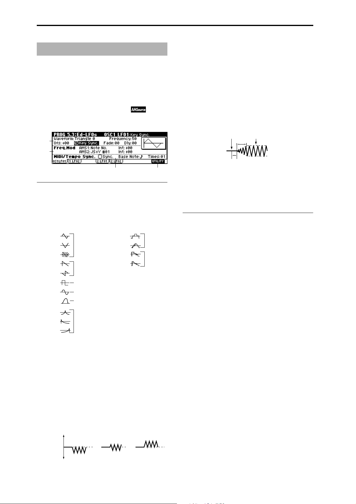
PROG 5.3: Ed–LFOs
Here you can make settings for the LFO that can be used to
cyclically modulate the Pitch, Filter, and Amp of oscillators 1
and 2. There are two LFO units for each oscillator. By setting
the LFO1 or LFO2 Intensity to a negative (–) value for Pitch,
Filter, or Amp, you can invert the LFO waveform.
5.3–1: OS1LFO1 (OSC1 LFO1)
Indicates settings for the “OSC1 LFO1,” which is the first
LFO that can be used for oscillator 1.
5.3–1a
5.3–1b
5.3–1c
5.3–1a: OSC1 LFO1
Waveform [Triangle 0…Random6 (Vect.)]
Selects the LFO waveform.
The numbers that appear at the right of some of the LFO
waveforms indicate the phase at which the waveform will
begin.
Triangle 0
Triangle 90
Triangle
Random
Saw 0
Saw 180
Square
Sine
Guitar
Exp.Triangle
Exp.Saw Down
Exp.Saw Up
Triangle wave
Phase will change
randomly at each key-in
Sawtooth down ↓
Square wave
Sine wave
Guitar vibrato
Step Triangle – 4
Step Triangle – 6
Step Saw – 4
Step Saw – 6
Random1 (S/H):
Conventional sample & hold (S/H) in which the
level changes randomly at fixed intervals of
time
Random2 (S/H):
Both the levels and the time intervals will
change randomly.
Random3 (S/H):
The maximum level and minimum level will
alternate at random intervals of time (i.e., a
square wave with random period).
Random4 (Vect.)
Random5 (Vect.)
Random6 (Vect.)
These types cause Random 1–3 to change
smoothly. They can be used to simulate the
instability of acoustic instruments etc.
Frequency [00…99]
Sets the LFO frequency. A setting of 99 is the fastest.
Ofs (Offset) [–99…+99]
Specifies the central value of the LFO waveform.
For example, with a setting of 0 as shown in the following
diagram, the vibrato that is applied will be centered on the
note-on pitch. With a setting of +99, the vibrato will only
raise the pitch above the note-on pitch, in the way in which
vibrato is applied on a guitar.
When “Waveform” is set to Guitar, the modulation will
occur only in the positive (+) direction even if you set “Offset” to 0.
Offset settings and pitch change produced by vibrato
offset = –99 offset = 0 offset = +99Pitch
5.3–1d
Key Sync. [Off, On]
On (checked): Key Sync. will be On. The LFO will start
each time you play a note, and an independent LFO will
operate for each note.
Off (unchecked): Key Sync. will be Off, and the LFO effect
that was started by the first-played note will continue to be
applied to each newly-played note. (In this case, Delay and
Fade will be applied only to the LFO when it is first started.)
Fade [00…99]
Specifies the time from when the LFO begins to apply until
it reaches the maximum amplitude. When “Key Sync.” is
Off, the fade will apply only when the LFO is first started.
How “Fade” affects the LFO (when “Key Sync.” is On)
Note-on Note-off
Fade
Delay
Dly (Delay) [0…99]
Specifies the time from note-on until the LFO effect begins to
apply.
When “Key Sync.” is Off, the delay will apply only when
the LFO is first started.
5.3–1b: Freq.Mod (Frequency Modulation)
You can use two alternate modulation sources to adjust the
speed of the OSC1 LFO1.
AMS1 (Freq. AMS1)
[Off, (PEG, FEG, AEG, LFO2, KT, EXT)]
Indicates the source that will adjust the frequency of the
oscillator 1 LFO1 (
☞p.222 “AMS List”). OSC1 LFO1 can be
modulated by OSC1 LFO2.
Int (AMS1 Intensity) [–99…+99]
Specifies the depth and direction of the effect that “AMS1
(Freq. AMS1)” will have.
When this parameter is set to a value of 16, 33, 49, 66, 82, or
99, the LFO frequency being can be increased by a maximum of 2, 4, 8, 16, 32, or 64 times respectively (or decreased
by 1/2, 1/4, 1/8, 1/16, 1/32, or 1/64 respectively).
For example, if “AMS1 (Freq. AMS1)” is Note No., positive
(+) values of this parameter will cause the oscillator 1 LFO
to speed up as you play higher notes. Negative (–) values
will cause the oscillator 1 LFO to slow down as you play
higher notes. This change will be centered on the C4 note.
If “AMS1 (Freq. AMS1)” is set to JS +Y #01, raising the value
of this parameter will cause the oscillator 1 LFO1 speed to
increase as the joystick is moved away from yourself. With a
setting of +99, moving the joystick all the way away from
yourself will increase the LFO speed by approximately 64
times.
AMS2 (Freq. AMS2)
[Off, (PEG, FEG, AEG, LFO2, KT, EXT)]
Int (AMS2 Intensity) [–99…+99]
Indicates settings for a second alternate modulation source
that will adjust the frequency of the oscillator 1 LFO1.
☞ “AMS1 (Freq. AMS1),” “Int. (AMS1 Intensity)”
24
Pitch at note-on
Page 35
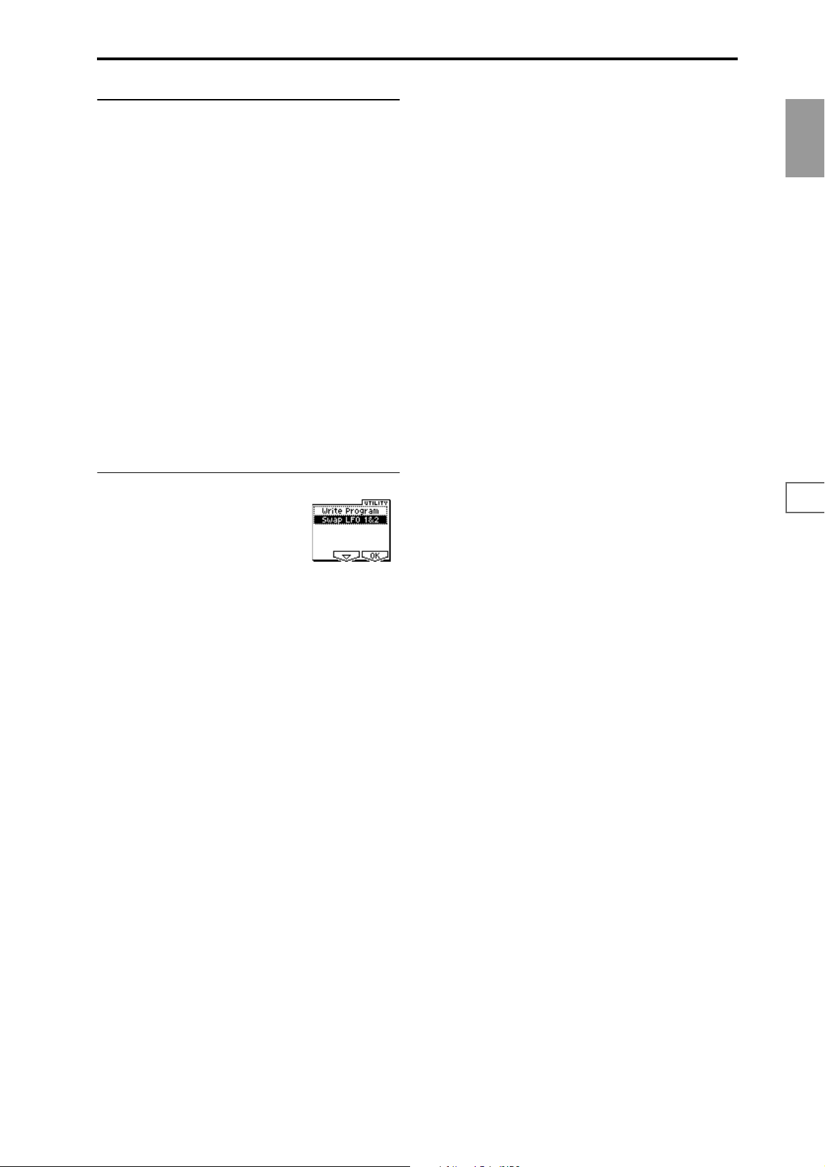
5.3–1c: MIDI/Tempo Sync.
(Frequency MIDI/Tempo Sync.)
Sync. (MIDI/Tempo Sync.) [Off, On]
On (checked): The LFO frequency will synchronize to the
tempo (MIDI Clock). In this case, the values you specified
for “Frequency” (5.3–1a) and “Freq.Mod” (5.3–1b) will be
ignored.
5.3–2: 1LFO2 (OSC1 LFO2)
Here you can make settings for the OSC1 LFO2, which is the
second LFO that can be applied to oscillator 1. (
OS1LFO1 (OSC1 LFO1)”) However, it is not possible to use
the LFO to apply modulation in “AMS1 (Freq. AMS1)” or
“AMS2 (Freq. AMS2)” of Freq. Mod.
☞“5.3–1:
PROG
1.1
Base Note (Sync. Base Note)
[ , , , , , , , ]
Times (Sync. Times) [01...16]
When “Sync. (MIDI/Tempo Sync.).” is checked, these When
“Sync. (MIDI/Tempo Sync.)” is checked, these parameters
specify a note length “Base Note (Sync. Base Note)” relative
to “ (Tempo)” and the multiple “Times (Sync. Times)” that
will be applied to it. These parameters will determine the
frequency of the OSC1 LFO1. For example if “Base Note
(Sync. Base Note)” is (quarter note) and “Times (Sync.
Times)” is 04, the LFO will perform one cycle every four
beats.
Even if you change the “ (Tempo)” setting of the KARMA
function, the LFO will always perform one cycle every four
beats.
■ 5.3–1d: UTILITY
☞ “Write Program” (1.1–1c)
For details on how to select the desired utility function, refer
to “PROG 1.1–1c: UTILITY.”
5.3–3: 2LFO1 (OSC2 LFO1)
This can be used when “Mode (Oscillator Mode)” (2.1–1a) is
set to Double. Here you can make settings for the OSC2
LFO1, which is the first LFO that can be applied to oscillator
2 (
☞“5.3–1: OS1LFO1 (OSC1 LFO1)”).
5.3–4: 2LFO2 (OSC2 LFO2)
This can be used when “Mode (Oscillator Mode)” (2.1–1a) is
set to Double. Here you can make settings for the OSC2
LFO2, which is the second LFO that can be applied to oscillator 2 (
☞“5.3–1: OS1LFO1 (OSC1 LFO1)” and “5.3–2:
OS1LFO2 (OSC1 LFO2)”).
2.12.22.33.14.14.25.15.25.36.16.26.36.47.17.27.3
Swap LFO 1&2
This exchanges the settings of LFO 1 and 2. If LFO2 is
selected in AMS1 (Freq. AMS1) or AMS2 (Freq. AMS2) of
LFO1 Freq.Mod (5.3–1b), the settings will be invalid for
LFO2 after LFO1 and 2 have been exchanged. If you select
this from the OSC1 LFO1 or OSC1 LFO2 page, LFO1 and
LFO2 of OSC1 will be exchanged.
1 Select “Swap LFO 1&2” to access the dialog box.
2 To execute, press the [F8] (“OK”) key. To cancel without
executing, press the [F7] (“Cancel”) key.
25
Page 36
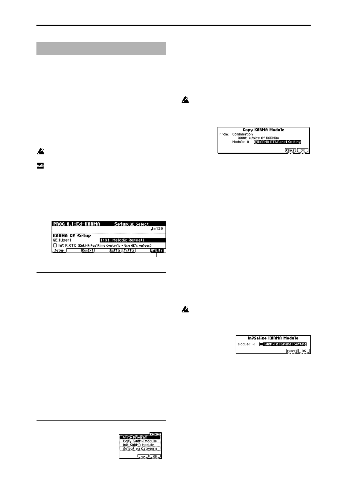
PROG 6.1: Ed–KARMA
Here you can make KARMA function settings for use by the
program. In Program mode you can use one KARMA module (module [A]).
When you switch programs, these settings will automatically be rewritten to the KARMA settings stored in that program. (
☞GLOBAL 1.1–1c: System Basic, Auto KARMA
“Program”: On)
The KARMA function can be turned on/off by the KARMA
real-time controls [ON/OFF] key.
The state of the KARMA real-time controls [LATCH]
[SCENE] keys, switches [1]/[2], and knobs [1]–[8], and the
note settings/velocity of the CHORD TRIGGER [1]–[4] keys
can be saved in each program.
In order for these settings to be valid, GLOBAL 1.1–1c:
System Basic, Auto KARMA “Program” must be On.
The PROG 6.1–1: Setup page parameters can also be set
from the PROG 1.1–3: KARMA page.
6.1–1: Setup
Here you can select the GE used by the KARMA module,
and make key zone and MIDI filter settings for the KARMA
module.
6.1–1a
6.1–1b
6.1–1c
6.1–1a: (Tempo)
Specifies the tempo at which the KARMA function will
operate. (
6.1–1b: GE Setup
GE Category [00: name ...]
This displays the category of the currently selected GE.
(
☞p.5)
☞p.3)
☞ “Write Program” (1.1–1c), “Select by Category” (1.1–3b)
For details on how to select the desired utility, refer to
“PROG 1.1–1c: UTILITY.”
Copy KARMA Module
This command copies the settings of the KARMA module
used by a specified program, combination, song, or song
play.
The “Input Channel” and “Output Channel” (6.2–1a)
settings of combination, song, or song play will not be
copied.
1 Select “Copy KARMA Module” to access the dialog box.
2 In “From,” select the copy source mode, bank, and num-
ber.
You can press a Bank [A]–[G] key to select the bank.
3 If the copy source is a combination, song, or song play,
you can also select the module that will be copied.
4 If you wish to copy KARMA RT parameters and
KARMA real-time CONTROLS settings as well, check
“KARMA RT&Panel Setting.”
Settings copied by “KARMA RT&Panel Setting”
• [ON/OFF] key setting
• [LATCH] key setting
• CHORD TRIGGER [1]–[4] key settings
• SCENE [1], [2] key settings
• KARMA real-time CONTROLS knobs [1]–[8],
switches [1]/[2] settings
• PROG 6.4: Ed-KARMA RT settings (RTParm,
DynMIDI, Name)
5 To execute the copy, press the [F8] (“OK”) key. To cancel
without executing press the [F7] (“Cancel”) key.
Init KARMA Module (Initialize KARMA Module)
This command initializes the settings of the KARMA module.
The GE selection will not be initialized. The GE parameter “Values” will be set to the default values that are
preset for the selected GE.
1 Select “Init KARMA Module” to access the dialog box.
GE Select [0000: Arp Model 1 Up/Dn…]
Indicates the GE. (☞p.3)
Init K.RTC (KARMA Real-time Controls–Use GE’s Value)
[Off, On]
Specifies whether the settings of the KARMA real-time controls knobs [1]–[8] and switches [1]/[2] will be initialized
when you select a GE.
This allows you to hear the original state of the phrase or
pattern produced by the GE. Normally you will turn this On
when selecting a GE. (
■ 6.1–1c: UTILITY
☞p.5)
26
2 If you also wish to initialize the KARMA RT parameters
and KARMA real-time Controls settings, check
“KARMA RT&Panel Setting.”
Settings that are initialized by “KARMA RT&Panel
Setting”
• 6.4: Ed-KARMA RT settings (RTParm, DynMIDI,
Name)
• KARMA real-time Controls knobs [1]–[8], switches
[1]/[2], [SCENE] key, [LATCH] key settings
• CHORD TRIGGER [1]–[4] key settings
3 To initialize the settings, press the [F8] (“OK”) key. To
cancel without initializing, press the [F7] (“Cancel”) key.
Page 37
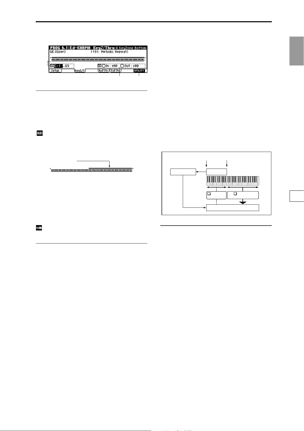
6.1–2: Key Z/T (KeyZ/Thru)
6.1–2a
6.1–2b
6.1–2a: Zone Map, KeyZone Bottom, KeyZone Top
The KARMA module is controlled by note data in numerous
ways, including the variation of phrase or pattern produced
by the GE, by trigger, and by chord detection.
Here you can specify the range of note data (key zone) that
will control the KARMA module.
In Program mode, all MIDI data for the KARMA module is transmitted and received on the Global MIDI
channel “MIDI Channel” (GLOBAL 2.1–1a).
Zone Map
Key zone
6.1–2c
Thru Out Zone [Off, On]
On (checked): Note data from keys outside the key zone
will be input directly to the tone generator. (They will not be
input to the KARMA module, since they are outside the key
zone.) When you play keys outside the key zone, the tone
generator will sound.
Off (unchecked): The tone generator will not sound even if
you play keys outside the key zone.
Transpose OutZ [–36...+36]
Specifies the transpose setting applied to note data from
keys outside the key zone.
Make this setting if you wish to apply a transposition in
semitone steps to the pitch of notes played from conventionally from the keyboard when “Thru Out Zone” is On.
You could select a bass program and make the settings
shown below.
Example
Using the KARMA module to control the bass line in the
lower range of the keyboard, and playing in real-time in the
upper range.
KeyZone Bottom
KeyZone Top
PROG
1.1
2.12.22.33.14.14.25.15.25.36.16.26.36.47.17.27.3
A solid line indicates the specified key zone.
Notes and messages from the MIDI IN connector within this
zone will be input to the KARMA module.
KeyZone Bottom [C–1...G9]
Specifies the bottom key (lower limit) of the key zone.
KeyZone Top [C–1...G9]
Specifies the top key (upper limit) of the key zone.
These parameters can also be set by holding down the
[Enter] key and pressing a note.
6.1–2b: Thru In Zone, Transpose InZ, Thru Out
Zone, Transpose OutZ
Specifies whether note data from the keyboard within or
outside of the key zone (6.1–2a) will be played while the
KARMA module plays phrases or patterns.
Thru In Zone [Off, On]
On (checked): Note data from keys within the key zone will
be input to the KARMA module, and will also be input
directly to the tone generator.
When you play a key within the key zone, the phrase or pattern generated by the KARMA module will sound, as will
the note itself.
Off (unchecked): Only the phrase or pattern generated by
KARMA will sound. Keys played within the key zone will
not sound.
KARMA Module
Bass line
Key Zone
Thru In Zone
Transpose InZ
✓
Tone generator
Thru Out Zone
Transpose OutZ
Realtime performance
■ 6.1–2c: UTILITY
☞ “Write Program” (1.1–1c), “Copy KARMA Module,” “Init
KARMA Module” (6.1–1c), “Select by Category” (1.1–3b)
Transpose InZ [–36...+36]
Specifies the transpose setting applied to note data from
within the key zone.
Make this setting if you wish to apply a transposition in
semitone steps to the pitch of notes played from the keyboard when “Thru In Zone” is On.
27
Page 38
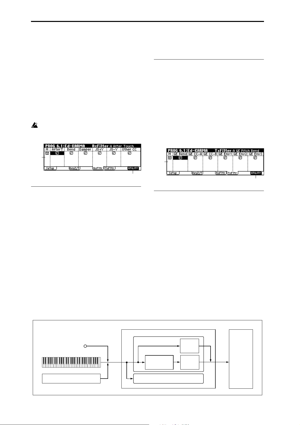
6.1–3: RxFltr (Receive Filter)
Specifies whether filters will be applied to the MIDI control
data received by the KARMA module before it is passed on
(echoed) to the tone generator.
On (checked): The corresponding MIDI data will be echoed
to the tone generator.
Off (unchecked): The corresponding MIDI data will not be
echoed to the tone generator.
When the KARMA module is on, the MIDI control data
received by the KARMA module will be transmitted to the
tone generator without change. Depending on these settings, you can (for example) make settings so that the
damper pedal is enabled when the KARMA module is off,
and disabled when it is on. (See the diagram below,
“KARMA Rx/Tx Filter.”)
These settings do not affect the Dynamic MIDI (PROG
6.4–3) settings. If you have specified MIDI control data
as the Dynamic MIDI source, it will be valid regardless
of these settings.
Other CC [Off, On]
Specifies whether MIDI control change messages other than
the above will be echoed to the tone generator.
■ 6.1–3b: UTILITY
☞ “Write Combination” (1.1–1c), “Copy KARMA Module,”
“Init KARMA Module” (6.1–1c), “Select by Category”
(1.1–3b)
6.1–4: TxFltr (Transmit Filter)
Specifies whether filtering will be applied to the MIDI control data produced by the GE selected for the KARMA module. (See the diagram below, “KARMA Rx/Tx Filter.”)
On (checked): The corresponding MIDI data will be transmitted from the KARMA module.
Off (unchecked): The corresponding MIDI data will not be
transmitted from the KARMA module.
6.1–3a
6.1–3b
6.1–3a: Rx Filter
AfterT (After Touch) [Off, On]
Specifies whether MIDI aftertouch messages will be echoed
to the tone generator.
Bend (Pitch Bend) [Off, On]
Specifies whether MIDI pitch bend messages will be echoed
to the tone generator.
Damper (Damper CC#64) [Off, On]
Specifies whether MIDI control change message #64 Hold
(damper pedal) will be echoed to the tone generator.
JS+Y (JS+Y CC#01) [Off, On]
Specifies whether MIDI control change message #1 (internal
joystick +Y direction, or specified as the B-assignment of a
real-time control knob) will be echoed to the tone generator.
JS-Y (JS-Y CC#02) [Off, On]
Specifies whether MIDI control change message #2 (internal
joystick -Y direction, or specified as the B-assignment of a
real-time control knob) will be echoed to the tone generator.
6.1–4a
6.1–4b
6.1–4a: Tx Filter
The GE can also automatically produce pitch bend and various types of control change data in addition to note data.
Three envelope generators can also be used to apply timevariant change to velocity, tempo, duration, and various
control changes such as pitch bend, JS +Y (CC#1) etc.
GE parameter group: (☞GE Guide)
Bend: Automatically generate pitch bend data in synchronization with the phrase or pattern.
CCs: Automatically generate the two control changes specified by CC-A and CC-B.
Envelopes: Use Envelope 1, Envelope 2, and Envelope 3 to
automatically generate velocity, tempo, duration, or control
changes such as pitch bend, JS +Y (CC#1) etc.
The data that is output will depend on the settings of the
parameters for the selected GE. For example, transmitting/
filtering pitch bend will produce no result if the GE has not
been designed to produce pitch bend data.
KARMA Rx/Tx Filter
28
MIDI IN
Controller
KARMA function
KARMA Module
GE
Dynamic MIDI
Rx Filter
Tx Filter
Tone
generator
Page 39

GE Bend (GE Pitch Bend) [Off, On]
Specifies whether to transmit the MIDI pitch bend messages
produced by the GE selected for the KARMA module.
This setting also applies to the pitch bend messages
produced by CC–A, CC–B, Envelope 1, Envelope 2, and
Envelope 3.
When KARMA function is on and the KARMA module
is producing pitch bend data, the pitch bend range of
the program will be controlled as follows.
The pitch bend range specified within KARMA GE will
automatically be transmitted from the KARMA module, and set within the program. This ensures that the
pitch bend data produced by the GE of the KARMA
will function correctly. At this time, in most cases the
pitch bend data, the pitch bend data produced when
you operate the joystick will automatically be optimized so that it will produce the same bend effect as if
KARMA were off. (In the case of a program whose
“OSC Mode” is Double, and whose OSC 1 and 2 “Pitch
JS (+X) and JS (–X) settings differ, the pitch bend will be
adjusted for OSC 1.)
GE CC-A/GE CC-B [Off, On]
Specifies whether to transmit the various MIDI messages
produced by CC–A/CC–B of the GE selected by the
KARMA module.
However if CC–A/CC–B are producing pitch bend messages, these settings will be ignored, and the “GE Bend” setting will be used.
GE Env.1/GE Env.2/GE Env.3 [Off, On]
Specifies whether to transmit the various MIDI messages
produced by Envelope 1, Envelope 2, and Envelope 3 of the
GE selected by the KARMA module. However if Envelope
1, Envelope 2, or Envelope 3 are producing pitch bend messages, these settings will be ignored, and the “GE Bend” setting will be used.
■ 6.1–4b: UTILITY
☞ “Write Program” (1.1–1c), “Copy KARMA Module,” “Init
KARMA Module” (6.1–1c), “Select by Category” (1.1–3b)
PROG 6.2: Ed-KARMA Mdl
Here you can set KARMA module parameters. In Program
mode, you can use one KARMA module (module [A]).
6.2–1: Parm1 (Parameter 1)
6.2–1a
6.2–1b 6.2–1c
6.2–1a: Module Parameters
Transpose [–36...+36]
Controls the pitch of the phrases or chords produced by the
KARMA module, in semitone steps.
The note data from the keyboard or the MIDI IN connector
will be input to the KARMA module. (
“KeyZone Top” (6.1–2a)). Here you can transpose the pitch
(in semitone steps) of the note data that is input to the
KARMA module.
☞“KeyZone Bottom,”
Force Range
[Off, Lowest, Highest, C3–B3[1], C3–B3[2]]
Control the pitch range of the phrases or chords produced
by the KARMA module.
Note data from the keyboard or the MIDI IN connector will
be input to the KARMA module (
“KeyZone Top” (6.1–2a), “Transpose” (6.2–1a)). Here you
can make settings so that the note data input to the KARMA
module is forcibly restricted to a specific range.
Off: The input notes will be sent to the KARMA module as
played, with no further alteration.
Lowest: The input notes will be forcibly restricted to be within
one octave of the lowest note.
If you play a chord of E2, E4, G#4, B4, and D#5 (i.e., E Maj7)
on the keyboard, the input notes will all be transposed to be
within an octave of the lowest note (E2): E2, G#2, B3, and D#3.
Highest: The input notes will be forcibly restricted to be
within one octave of the highest note.
If you play a chord of E2, E4, G#4, B4, and D#5 (i.e., E Maj7) on
the keyboard, the input notes will all be transposed to be within
an octave of the highest note (D#5): E4, G#4, B4, and D#5.
Played on keyboard:
E2 E4 G#4 B4 D#5 (play an EMaj7 chord)
↓
Lowest: input notes transposed to E2 G#2 B3 D#3
Highest: input notes transposed to E4 G#4 B4 D#5
C3–B3[1]: The input notes will be forcibly restricted to be
near the middle octave (C3–B3). The lowest note will have
the pitch of the lowest note played, and the other input
notes will be transposed as far as possible so as to maintain
the chord inversion. This is effective when you wish to produce phrases or patterns having a similar inversion to what
was played, but in a fixed range regardless of where you are
playing on the keyboard.
C3–B3[2]: The input notes will be forcibly restricted to be
within the center octave (C3–B3). Since all notes will be
forced into the center octave (C3–B3), the chord inversion
will change significantly; for example the bass note may
change. This is effective when you want to absolutely limit
the input notes to a specific octave.
☞“KeyZone Bottom,”
6.2–1d
PROG
1.1
2.12.22.33.14.14.25.15.25.36.16.26.36.47.17.27.3
29
Page 40
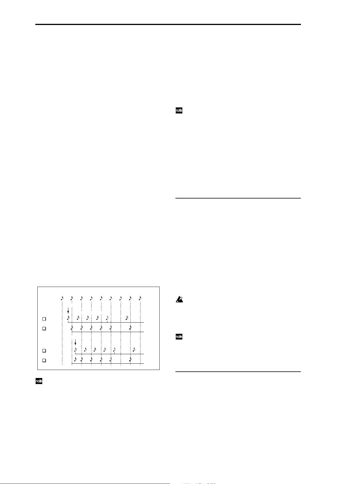
Played on keyboard:
Play chords in the order of
E4 G#4 B4 D#5 (EMaj7 first inversion)
G#4 B4 D#5 E5 (EMaj7 second inversion)
B4 D#5 E5 G#5 (EMaj7 third inversion)
D#5 E5 G#5 B5 (EMaj7 fourth inversion)
↓
C3–B3[1]:
Transpose the input notes to:
E3 G#3 B3 D#4 (EMaj7 first inversion)
G#2 B2 D#3 E3 (EMaj7 second inversion)
B2 D#3 E3 G#3 (EMaj7 third inversion)
D#3 E3 G#3 B3 (EMaj7 fourth inversion)
C3–B3[2]
D#3 E3 G#3 B3 (EMaj7/D#)
D#3 E3 G#3 B3 (EMaj7/D#)
D#3 E3 G#3 B3 (EMaj7/D#)
D#3 E3 G#3 B3 (EMaj7/D#)
(all identical)
Delay Start [Off, Fixed, 3...4x]
Specify the delay from when the trigger (by note data) is
input, until the phrase or pattern starts.
3...4x:Specify the delay time as a note value interval rela-
tive to the tempo.
Fixed: The delay time will be specified in time units (ms).
Set the time in “Delay Start Fixed.”
Delay Start Fixed [0000 ms ... 5000 ms]
This is valid if “Delay Start” is set to Fixed.
Set “Delay Start” in ms units.
Quantize Trig [Off, On]
Quantize (correct) the timing of the triggering caused by the
note data or Dynamic MIDI.
On (checked): Trigger timing will be quantized in 16th note
units relative to the basic tempo.
Off (unchecked): Triggering will occur at the moment you
play the keyboard or activate a trigger through Dynamic
MIDI.
Trigger
KARMA GE Phrase / Pattern
Quantize Trig
✓
Quantize Trig
Trigger
Quantize Trig
✓
Quantize Trig
Regular (i.e. Scalic, Scalic 2, etc.), will cause the Note Series
to be created in root position, regardless of the inversion of
the Chord. In other words, when this is Off (Unchecked), if
you play CMaj/E, the Note Series will start from E and continue up, or if you play CMaj/G, the Note Series will start
with G. By using “Root Position” On (Checked), you can
make sure that any inversion of a chord ends up the same.
For example, CMaj/E and CMaj/G will both be the same as
CMaj, and the Note Series will start from a C. This can allow
a GE to behave more predictably with all inversions of a
☞GE Guide “Note Series”)
chord. (
When the GE-Type is Generated-Drum, the notes come
from Drum Patterns and not the Note Series. The drum
patterns can be used to generate melodies, in addition
to drum and percussion grooves. “Root Position” also
has a similar effect on how the Drum Patterns are transposed, but only if “Drum-Track Keyboard” is on. (☞GE
Guide “Drum”). Also when the GE-Type is Generated-
Drum, if using
arpeggiated pitch-bending (based on the Note Series),
the resulting pitch bend data will be affected also (
☞GE
Guide “Bend”). When the GE-Type is Real-time, this
parameter has no effect unless you are using Dynamic
MIDI to Direct Index the Note Series (
☞p.234
“Dynamic MIDI Sources & Destinations”).
6.2–1b: Tx CC (Transmit CC)
When KARMA function is turned on, MIDI control change
messages are transmitted to the tone generator. Make these
settings when you wish to control the program sound or
effects etc. when KARMA function is turned on.
Tx CC1 Number [Off, 000...095]
Tx CC2 Number [Off, 000...095]
Tx CC3 Number [Off, 000...095]
Tx CC4 Number [Off, 000...095]
Selects the MIDI control change message that will be transmitted.
The value of the transmitted message is specified by “Value
(Tx CC Value)” (6.2–1c).
If the KARMA [ON/OFF] key is on, the specified MIDI
control change message will be transmitted when you
select a program whose KARMA [ON/OFF] key is
turned on. If the selected GE produces the control
change specified here, the effect of the control change
produced by GE will be given priority.
The MIDI control change messages specified here for
transmission and the MIDI control change messages
produced by the selected GE when the KARMA [ON/
OFF] key is on will be reset automatically when the
KARMA [ON/OFF] key is turned off.
When this is On, triggering at a timing that is within a
32nd note of the 16th note base value will cause the
playback to begin simultaneously (lower row of the
preceding diagram). If the trigger is later than this,
playback will start at the next 16th note (upper row of
the diagram above).
Root Position [Off, On]
The phrases and patterns produced by a KARMA module
are generated by a GE (Generated Effect). In most cases, this
is done based on a Note Series. When “Root Position” is On
(Checked), any “Note Type” (GE parameter:
☞VNL) except
30
6.2–1c: Value (Tx CC Value)
Value (Tx CC1 Value) [000...127]
Value (Tx CC2 Value) [000...127]
Value (Tx CC3 Value) [000...127]
Value (Tx CC4 Value) [000...127]
Specifies the value of the message that will be transmitted.
This will have no effect if “Tx CC Number” is Off.
Page 41

■ 6.2–1d: UTILITY
☞ “Write Program” (1.1–1c), “Copy KARMA Module,” “Init
KARMA Module” (6.1–1c), “Select by Category” (1.1–3b)
6.2–2: Parm2 (Parameter 2)
6.2–2a
6.2–2c6.2–2b
6.2–2a: Trigger/Latch
Set trigger conditions and latch on/off for the GE selected
for the KARMA module. Settings are made independently
for Note, Env.1, Env.2, and Env.3.
Note:
Specifies the trigger conditions for the phrase or pattern produced by the GE, and set latch on/off.
Note Trigger [Any, AKR, 1st, Dyn]
With any of these settings, the trigger will be applied by
operations of the controller specified for Dynamic MIDI
(6.4–3) (if “Destination” is set to Trig Nt&Env, Trig
Notes.
☞p.234 “Dynamic MIDI Sources & Destinations”)
Any (Any Note + Dynamic MIDI): Every note-on will cause
triggering; i.e., each note-on will cause the phrase or pattern
to restart from the beginning.
AKR (1st Note After Key Release + Dynamic MIDI): Triggering will occur when the first note-on occurs from a state
in which no keys are “on.” Triggering will not occur if even
one note is being pressed. By changing the chord you play
on the keyboard while holding at least one note, you can
control the phrase or pattern without triggering.
1st (1st Only Until Module Stops + Dynamic MIDI): After
KARMA function is turned on, only the first note-on will cause
triggering. Subsequent note-ons will not cause triggering.
Dyn (Dynamic MIDI): Triggering will be produced by operating the controller specified by Dynamic MIDI (6.4–3). In
this case, note-ons will not cause triggering.
Note Latch [Off, On]
Specifies whether the phrase or pattern will continue when
you release your hand from the keyboard (latch on) or
whether the phrase or pattern will stop (latch off). In Program mode, turn this On and use the [LATCH] key to control latch on/off.
Off (unchecked): Latch will be off regardless of the
[LATCH] key on/off status.
On (checked): The [LATCH] key will control latch on/off.
When the [LATCH] key is off (LED dark), latch is off.
When the [LATCH] key is on (LED lit), latch is on.
In Combination, Sequencer, and Song Play mode, up to
four KARMA modules can be used. In these modes,
you can turn “Note Latch” on/off independently for
each KARMA module. If you use “Copy KARMA Module” to copy KARMA module settings from these
modes to a program, there may be cases in which the
setting here will be off, so that latch-on will not occur
even if you turn on the [LATCH] key. In such cases,
turn this on.
Env1: Env2: Env3:
Each GE provides three Envelopes. They can produce timevariant control of velocity, tempo, duration, pitch bend, and
various control changes.
You can specify triggering conditions and latch conditions
for each of the three Envelopes of the GE.
If the selected GE does not use Envelopes, these settings
will have no effect.
Env1 Trigger/Env2 Trigger/Env3 Trigger
[Any, AKR, 1st, Dyn]
For any of these settings, triggering will be applied by
operations of the controller specified for Dynamic MIDI
(6.4–3) (if “Destination” is set to Trig Nt&Env, Trig
Env1...Trig Env3).
Any (Any Note + Dynamic MIDI): Every note-on will cause
triggering; i.e., each note-on will cause the envelope to start
from the beginning.
AKR (1st Note After Key Release + Dynamic MIDI): Triggering will occur when the first note-on occurs from a state
in which no keys are “on.” Retriggering will not occur if
even one note is being pressed.
1st (1st Only Until Module Stops + Dynamic MIDI): After
KARMA is turned on, only the first note-on will cause triggering. Subsequent note-ons will not cause triggering.
Dyn (Dynamic MIDI): Triggering will be produced by operating the controller specified by Dynamic MIDI (6.4–3). In
this case, note-ons will not cause triggering.
Env1 Latch/Env2 Latch/Env3 Latch
[Off, Sus1, Rel1, Sus2, Rel2]
Off: The envelope will not be latched. When all keys are
released or a Dynamic MIDI trigger is released (note-off),
the envelope will move to the release segment.
Sus1: Once the envelope is started, it will proceed through
attack → decay → sustain → release. If note-off occurs
before the envelope reaches the sustain level, the envelope
will not begin the release immediately but wait until after
reaching the sustain level. Even in the case of a note for
which the note-on/off interval is short, the envelope will
proceed through attack → decay → sustain → release as if
the key was being held for a longer time. If the envelope
reaches the sustain level before receiving note-off, it will
stop at the sustain level (the same operation as for the Off
setting). If the note-off occurs after the envelope reaches the
sustain level, the envelope will begin the release when noteoff occurs (the same operation as for the Off setting).
If the note-off occurs after the envelope reaches the sustain
level, the envelope will begin the release when note-off
occurs (the same operation as for the Off setting).
Rel1: Once the envelope has started, it will proceed through
attack → decay → release, regardless of when the note-off
occurs. Even if a key is being pressed, the envelope will
ignore sustain, and will proceed immediately to the release.
Sus2: The envelope will ignore note-off, and will procee
through attach → decay → sustain. Therefore, this setting
will never reach the release portion. Other operation is the
same as for Sus1.
Rel2: The same operation as Rel1, except will ignore noteoff for the purpose of looping, as explained below.
The envelope can be set to repeat as a loop as part of the GE.
A looped envelope will be controlled as follows.
For Sus1 and Rel1, the envelope will continue repeating as
long as the key is held.
For Sus2 and Rel2, the envelope will continue repeating
even if the key is released.
PROG
1.1
2.12.22.33.14.14.25.15.25.36.16.26.36.47.17.27.3
31
Page 42

6.2–2b: Clock Advance
Here you can make settings for the clock that will operate
the KARMA module. By using these settings in conjunction
with the Dynamic MIDI (6.4–3) function, you can use Man-
ual Advance by operating controllers such as the joystick to
trigger the clock that operates KARMA module, causing the
phrase or pattern to advance.
Mode (Clk Adv. Mode) [Auto...Auto+Dyn2]
Auto: The KARMA module will operate according to the
“Te mp o” (1.1–1a) setting. If “MIDI Clock” (Global 2.1–2a) is
External, the KARMA module will operate in synchronization with the MIDI clock from the External MIDI device.
Normally you will select Auto.
Dyn: The clock by which the KARMA module will operate
can be triggered by operating the joystick or other controller
according to the Dynamic MIDI (6.4–3) setting, causing the
phrase or pattern to advance. (Set Dynamic MIDI (6.4–3a/
b/c/d) “Destination” to Clock Adv.)
You can input a chord from the keyboard, and use the joystick to “strum” guitar chords, or use note-on/off to
advance through the arpeggio pattern.
Auto+Dyn1: The KARMA module will operate according to
both Auto and Dyn.
Auto + Dyn2: The KARMA module will operate according
to both Auto + Dyn, except that a trigger received from
Dynamic MIDI will momentarily stop the automatic
advancement until the KARMA module playback is
restarted.
Size (Clk Adv. Size) [3... , Event]
This is valid when “Mode” is Dyn, Auto + Dyn1 or Auto +
Dyn2. It specifies the unit by which the phrase or pattern
will be advanced when the controller is operated.
3... : The phrase or pattern will be advanced by the speci-
fied note value, synchronized to the rhythm of the phrase or
pattern.
Event: The phrase or pattern will be advanced by one note
or one chord, ignoring the rhythm of the phrase or pattern.
VelSensBtm (Vel Sens Bottom) [001...127]
This is valid when “Mode” is Dyn, Auto + Dyn1 or Auto +
Dyn2. If the Dynamic MIDI “Source” is Note or Velocity, the
phrase will be produced by applying the velocity of each
Manual Advance trigger that is input to the KARMA module to the notes as they are generated. This parameter specifies the lower limit of a scaled range that the velocity is
adjusted by before being applied.
With a setting of 001, the velocity data will be input to the
KARMA module with an unmodified range of 1–127.
With a setting of 064, velocity data in the range of 1–127 will
be scaled to the range of 64–127 before it is input to the
KARMA module.
■ 6.2–2c: UTILITY
☞ “Write Program” (1.1–1c), “Copy KARMA Module,” “Init
KARMA Module” (6.1–1c), “Select by Category” (1.1–3d)
PROG 6.3: Ed-KARMA GE
Here you can edit the parameters of the GE selected for the
KARMA module. By assigning GE parameters to KARMA
real-time CONTROLS, you can control the phrase or pattern
in real-time while you play.
6.3–1: GE P...4 (GE Parameter 1...4)
6.3–1: GE P...8 (GE Parameter 5...8)
6.3–1: GE P...12 (GE Parameter 9...12)
6.3–1: GE P...16 (GE Parameter 13...16)
ChdMode (Chord Mode)
[Off, 1st,Chrd1, Chrd2, Chrd3]
This is valid when “Mode” is Dyn, Auto + Dyn1 or Auto +
Dyn2. It specifies how a chord will be sounded when that
chord is input from the keyboard.
Off: There will be no sound when you input a chord from
the keyboard. This is analogous to a guitarist changing
chords in the left hand. The phrase or pattern will sound
from the first step when you operate the controller.
1st: When you input a chord from the keyboard, the first
step of the phrase or pattern will sound. When you operate
the controller, the phrase or pattern will continue advancing.
Chrd1: When you input a chord from the keyboard, the first
several steps of the phrase or pattern will sound, according
to the number of notes that you input. When you operate
the controller, the phrase or pattern will continue advancing.
Chrd2: When you input a chord from the keyboard, it will
sound in the same way as for Chrd1. However, the phrase or
pattern will play from the beginning of the pattern when
you operate the controller.
Chrd3: When you input a chord from the keyboard, it will
sound in the same way as for Chrd1. However, the phrase or
pattern will start from the second step when you operate the
controller. When simulating acoustic guitar finger picking,
this allows you to create a natural connection between the
played chord and the finger picking sounded by the controller.
6.3–1a
6.3–1b
6.3–1(2)(3)(4)a: GE Parameter, Value, Asgn
(Assign), Pol (Polarity)
GE Parameter (GE real-time Parameter)
This shows the GE parameters selected for the KARMA
module.
Each GE has up to 16 preset parameters that are suitable for
controlling the phrase or pattern. The GE parameters displayed will depend on the selected GE.
For details on the GE parameters, refer to GE Guide.
Value (GE real-time Parameter Value)
Sets the value of each GE parameter.
If you use GE Select (1.1–3a, 6.1–1b) to select a GE, the
default values that are preset for each GE will be specified.
The range of the values are also preset for each GE.
The value you specify here will be the center value when the
KARMA real-time CONTROLS knobs etc. are used to control these parameters.
32
Page 43

Asgn (GE real-time Parameter Assign)
[---, ...Dyn4]
Here you can assign the controller for the GE parameter.
By assigning GE parameters to KARMA real-time CONTROLS, they can be controlled in real-time while you play.
---: No assignment.
... (Knob 1...8): Assigns the parameter to KARMA
real-time CONTROLS knobs [1]–[8]. The knob will continuously control the “value.”
For example, let’s assume that the “Rhythm Swing%”
parameter of the selected GE has a Value range of +0000–
+0100.
• If you set “Value”: +0050, “Asgn (Assign)”: Knob 1, and
[Pol (Polarity)]:+
Knob 1 at the center position (12 o’clock) will produce a
value of +0050. At far left the value will be +0000, and at
far right the value will be +0100. Turning the knob from
center toward the left will control the value from
+0050...+0000, and turning it from center toward the
right will control the value from +0050...+0100.
• If you set “Value”: +0080, “Asgn (Assign)”: Knob1, and
”Pol (Polarity)”:+
Knob 1 at the center position (12 o’clock) will produce a
value of +0080. At far left the value will be +0000, and at
far right the value will be +0100. Turning the knob from
center toward the left will control the value from
+0080...+0000, and turning it from center toward the
right will control the value from +0080...+0100.
... (Knob 1...8SW): Assign the parameter to
KARMA real-time CONTROLS knobs [1]–[8]. The knob will
switch the value between minimum and maximum only, in
a key (on/off) operation. The left range of the knob is off,
and the center and right is on.
• If you set “Value”: +0050, “Asgn (Assign)”: Knob 1SW,
and [Pol (Polarity)]:+
Turning the knob toward the left will produce a value of
+0000. Turning it to center or right will produce a value
of +0100.
... : The parameter will be assigned to switch [1]/[2].
The “Value” will be controlled between the minimum and
maximum values.
The maximum and minimum values controlled by
Knob1–8SW and SW1/2 will depend on the “Value”
setting.
[Example]
GE parameter Value range: in the case of 0...100
“Value” setting: +0050
Minimum value controlled by Knob1–8SW, SW1/2: 0
Maximum value controlled by Knob1–8SW, SW1/2: 100
“Value” setting: +0025
Minimum value controlled by Knob1–8SW, SW1/2: 0
Maximum value controlled by Knob1–8SW, SW1/2: 50
“Value” setting: +0075
Minimum value controlled by Knob1–8SW, SW1/2: 50
Maximum value controlled by Knob1–8SW, SW1/2: 100
The correspondence between the KARMA real-time
CONTROLS and MIDI control change messages can be
specified in Global mode 6.1–2. In this case, a MIDI control change message value of less than 64 will be “off,”
and 64 or greater will be “on.”
Dyn 1...4: This corresponds to Dynamic MIDI 1...4.
Select this if you wish to control a GE parameter using the
controller selected for “Source” in Dynamic MIDI (6.4–3a/
b/c/d). (Set the Dynamic MIDI (6.4–3a/b/c/d) “Destination” to RTParm Ctrl.)
Pol (GE real-time Parameter Polarity) [+, –]
Specifies the polarity used when you operate the KARMA
real-time CONTROLS that you selected for “Asgn.”
+: In the case of Knob1...8, rotating to the left of center will
lower the “Value,” and rotating to the right will raise it.
In the case of Knob1...8SW, the left side will be off, and
the center and right side will be on.
In the case of SW1/2, the parameter will be on when the
LED is lit.
–: In the case of Knob1...8, rotating to the left of center will
raise the “Value,” and rotating to the right will lower it.
In the case of Knob1...8SW, the left side will be on, and
the center and right side will be off.
In the case of SW1/2, the parameter will be on when the
LED is dark.
■ 6.3–1(2)(3)(4)b: UTILITY
☞ “Write Program” (1.1–1c), “Copy KARMA Module,” “Init
KARMA Module” (6.1–1c), “Select by Category” (1.1–3d)
PROG
1.1
2.12.22.33.14.14.25.15.25.36.16.26.36.47.17.27.3
33
Page 44

PROG 6.4: Ed-KARMA RT
6.4–1: RTP ..4 (RT Parameter 1...4)
6.4–2: RTP ..8 (RT Parameter 5...8)
Here you can assign controllers for 29 different KARMA
parameters (RT Parms) other than the GE parameters such
as the KARMA key zone parameters (6.1–2a, 6.1–2b) and
KARMA module parameters (6.2–1a, 6.2–2a, 6.2–2b).
By assigning these to KARMA real-time CONTROLS, you
can control them in real-time while you play.
In RT Parm 1–8, if you select a parameter by “Grp” and
“Parameter” and check “Module A,” that parameter
can no longer be edited as a KARMA key zone parameter (6.1–2a, 6.1–2b) or KARMA module parameter (6.2–
1a, 6.2–2a, 6.2–2b).
6.4–1a
6.4–1b
6.4–1c
6.4–1d
6.4–1e
6.4–1(2)a/b/c/d: RT Parm 1...4, RT Parm 5...8
Grp (Parm Group) [Off, Mix, Ctrl, Trig, Zone]
Indicates the group of parameters that you wish to assign.
The 29 KARMA parameters are divided into four groups,
and the parameters that can be assigned in “Parameter” will
differ according to the group.
Parameter [---, Transpose ... Tr.Oct/5 OutZ]
Indicates the parameter that you wish to assign.
The parameters that can be selected will differ according to
the group you selected in “Grp.”
Each of the parameters you select here corresponds to a
KARMA key zone parameter or module parameter that
can be set in 6.1 or 6.2. If you select “Grp” and “Parameter” in RT Param 1–8 and check “Module A,” that
parameter can no longer be edited as the corresponding
parameter of 6.1 or 6.2.
Group: Mix
Transpose [–36...+36]
Assigns the “Transpose” (6.2–1a) function.
Control the transposition in semitone steps.
Trnsp.Oct [–36...+36]
Assigns the “Transpose” (6.2–1a) function.
Control the transposition in octave steps.
Trnsp.Oct/5 [–36...+36]
Assigns the “Transpose” (6.2–1a) function.
Control the transposition in steps of an octave and a fifth.
Group: Ctrl
Quantize Trig [0, +1]
Assigns the “Quantize Trig” (6.2–1a) function.
0: Off
1: On
☞ p.30 “Quantize Trig” (6.2–1a)
Root Position [0, +1]
Assigns the “Root Position” (6.2–1a) function.
0: Off
1: On
☞ p.30 “Root Position” (6.2–1a)
Force Range [0...+4]
Assigns the “Force Range” (6.2–1a) function.
0: Off
1: Lowest
2: Highest
3: C3–B3[1]
4: C3–B3[2]
☞ p.29 “Force Range” (6.2–1a)
ClkAdv Mode [0...+3]
Assigns the “Mode (Clk Adv. Mode)” (6.2–2b) function.
0: Auto
1: Dyn
2: Auto+Dyn1
3: Auto+Dyn2
☞ p.32 “Mode (Clk Adv. Mode)” (6.2–2b)
ClkAdv Size [0...+11]
Assigns the “Size (Clk Adv. Size)” (6.2–2b) function.
0...10: 3...
11: Event
☞ p.32 “Size (Clk Adv. Size)” (6.2–2b)
ClkAdv Vel [001...127]
Assigns the “VelSensBtm” (6.2–2b) function.
☞ p.32 “VelSensBtm” (6.2–2b)
ClkAdv Chord [0...+4]
Assigns the “ChdMode” (6.2–2b) function.
0: Off
1: 1st
2: Chrd1
3: Chrd2
4: Chrd3
☞ p.32 “ChdMode” (6.2–2b)
Group: Trig
Dly Start [0...+25]
Assigns the “Delay Start” (6.2–1a) function.
0: Off
1: Fixed
2…25: 3...4x
☞ p.30 “Delay Start” (6.2–1a)
Dly Start ms [0...+5000]
Assigns the “Delay Start Fixed” (6.2–1a) function.
☞ p.30 “Delay Start Fixed” (6.2–1a)
Note Trigger [0...+3]
Assigns the “Note Trigger” (6.2–2a) function.
0: Any
1: AKR
2: 1st
3: Dyn
☞ p.31 “Note Trigger” (6.2–2a)
34
Page 45

Note Latch [0, +1]
Assigns the “Note Latch” (6.2–2a) function.
0: Off
1: On
☞ p.31 “Note Latch” (6.2–2a)
Env1 Trigger/Env2 Trigger/Env3 Trigger [0...+3]
Assigns the “Env1 Trigger”/“Env2 Trigger”/“Env3 Trigger”
(6.2–2a) functions.
0: Any
1: AKR
2: 1st
3: Dyn
☞ p.31 “Env1 Trigger”/“Env2 Trigger”/“Env3 Trigger”
(6.2–2a)
Env1 Latch/Env2 Latch/Env3 Latch [0...+4]
Assigns the “Env1 Latch”/“Env2 Latch”/“Env3 Latch”
(6.2–2a)
0: Off
1: Sus1
2: Rel1
3: Sus2
4: Rel2
☞ p.31 “Env1 Latch”/“Env2 Latch”/“Env3 Latch” (6.2–2a)
Group: Zone
Thru InZone [0, +1]
Assigns the “Thru In Zone” (6.1–2b) function.
0: Off
1: On
☞ p.27 “Thru In Zone” (6.1–2b)
Thru OutZone [0...+1]
Assigns the “Thru Out Zone” (6.1–2b) function.
0: Off
1: On
☞ p.27 “Thru Out Zone” (6.1–2b)
Key Zone Btm [0...+127]
Assigns the “KeyZone Bottom” (6.1–2a) function.
0...127: C-1–G9 (corresponds to note numbers)
☞ p.27 “KeyZone Bottom” (6.1–2a)
Key Zone Top [0...+127]
Assigns the “KeyZone Top” (6.1–2a) function.
0...127: C-1–G9 (corresponds to note numbers)
☞ p.27 “KeyZone Top” (6.1–2a)
Trnsp. InZ [–36...+36]
Assigns the “Transpose InZ” (6.1–2b) function.
This controls transposition of the note data from the keyboard within the key zone, in semitone steps.
☞ p.27 “Transpose InZ” (6.1–2b)
Trnsp. OutZ [–36...+36]
Assigns the “Transpose OutZ” (6.1–2b) function.
This controls the transposition of note data from the keyboard outside the key zone, in semitone units.
☞ p.27 “Transpose OutZ” (6.1–2b)
Tr.Oct InZ [–36...+36]
Assigns the “Transpose InZ” (6.1–2b) function.
This controls the transposition of note data from the keyboard within the key zone, in octave units.
Tr.Oct OutZ [–36...+36]
Assigns the “Transpose OutZ” (6.1–2b) function.
This controls the transposition of note data from the keyboard outside the key zone, in octave units.
Tr.Oct/5 InZ [–36...+36]
Assigns the “Transpose InZ” (6.1–2b) function.
This controls the transposition of note data from the keyboard within the key zone, in units of an octave and a fifth.
Tr.Oct/5 OutZ [–36...+36]
Assigns the “Transpose OutZ” (6.1–2b) function.
This controls the transposition of note data from the keyboard outside the key zone, in units of an octave and a fifth.
Min (Parm Min Value) [---, –0036...+5000]
Specifies the minimum value that will be operated by the
controller.
The available values will depend on the selected parameter.
When the parameter is selected, the minimum parameter
value will be set as the default.
Max (Parm Max Value) [---, –0036...+5000]
Specifies the maximum value that will be operated by the
controller.
The available values will depend on the selected parameter.
Val (Parm Value) [---, –0036...+5000]
Specifies the value of the selected KARMA parameter.
If you check “A (Parm Module A)” and select “Parameter,”
this will be set as the current value of the parameter (set in
6.1 and 6.2).
The value you specify here will be the center value when
you use “Asgn” to control the parameter from the KARMA
real-time CONTROLS knobs, etc.
A (Parm Module A) [Off, On]
Specifies the module to which the settings of RT Parm 1–8
will apply.
In Program mode, only one KARMA module (module [A])
can be used. Thus in Program mode, you can turn the RT
Parm 1–8 settings on/off.
On (checked): RT Parm settings will be valid.
Off (unchecked): RT Parm settings will be ignored.
Asgn (Parm Assign) [---, ...Dyn4]
Assigns the selected parameter to a controller.
If you assign a parameter to KARMA real-time CONTROLS,
you can control it in real-time while you play.
☞ 6.3–1a: “Asgn” (GE real-time Parameter Assign)
■ 6.4–1(2)e: UTILITY
☞ “Write Program” (1.1–1c), “Copy KARMA Module,” “Init
KARMA Module” (6.1–1c)
PROG
1.1
2.12.22.33.14.14.25.15.25.36.16.26.36.47.17.27.3
35
Page 46

6.4–3: DynMIDI (Dynamic MIDI)
Dynamic MIDI is a function that lets you use this instrument’s controllers and MIDI control messages to control
specific KARMA functions.
You can take advantage of this to control KARMA in various
ways while you play. For example, Manual Advance (6.2–
2b) lets you use joystick or note-on to advance the KARMA
clock. Or you can use a foot switch to control Auto Trans-
pose, or a damper pedal to control the KARMA latch.
6.4–3a
6.4–3b
6.4–3c
6.4–3d
6.4–3e
6.4–3a/b/c/d: Dyn MIDI1...4
Input (Dyn1...4 Input Module)
In Program mode this is fixed at A.
This is because only KARMA module [A] is used. This setting cannot be changed.
Source (Dyn1...4 Source) [Off, JS+Y #01...Vel Out Z]
Indicates the controller etc. that will be the Dynamic MIDI
source.
(
☞p.234 “Dynamic MIDI Source and Distnation”)
Btm (Dyn1...4 Range-Btm) [000...127]
Specifies the lower limit for the value controlled by
“Source.”
If “Source” is Short Note, Note No., White Note, or Black
Note, the numeric value corresponds to the note numbers C-
1–G9.
Top (Dyn1...4 Range-Top) [000...127]
Specifies the upper limit for the value controlled by
“Source.”
If “Source” is Short Note, Note No., White Note, or Black
Note, the numeric value corresponds to the note numbers C-
1–G9.
Act (Dyn1...4 Src Action) [M, T, C]
Specifies the operation mode for Dynamic MIDI.
M (Momentary): The parameter will be controlled as a
switch. For example if “Source” is JS+Y #01, the parameter
will normally be off, and will be on when you move the joystick.
If “Pol” (Dyn1...4 Polarity) is “+” and the source controller value is “Btm (Dyn1...4 Range-Btm)” this will be
off. If the controller value is “Top (Dyn1...4 Range-
Top),” it will be on.
[Example]
When “Btm (Dyn1...4 Range-Btm)”: 000 and “Top
(Dyn1...4 Range-Top)”: 127
The controller value and the on/off status are related as
follows.
000 → 127: on at 127
127→ 000: off at 000
T (Toggle): The parameter will be controlled as a switch. For
example if “Source” is JS+Y #01, the parameter will alternate between on/off each time you move the joystick.
If “Pol” (Dyn1...4 Polarity) is “+,” on and off will alternate each time the source controller value exceeds the
“Top (Dyn1...4 Range-Top)” value after having passed
through the “Btm (Dyn1...4 Range-Btm)” value.
[Example]
When “Btm (Dyn1...4 Range-Btm)”: 0 and “Top
(Dyn1...4 Range-Top)”: 127
The controller value and the on/off status are related as
follows.
000 → 127: on → off at 127
127 → 000 → 127: on → off at 127
(127 → 001 → 127: no change)
C (Continuous): The parameter will be controlled continuously.
The operating modes that can be selected are limited by
the “Destination.” (
Destinations”)
☞p.234 “Dynamic MIDI Sources &
Destination (Dyn1...4 Destination)
[Off, RTParm Ctrl...Buffer Latch]
Select the Dynamic MIDI control destination function.
(
☞p.235 “Dynamic MIDI Destinations”)
Pol (Dyn1...4 Polarity) [+, –, +/–, –/+]
Specifies the Dynamic MIDI polarity.
For example if you set “Pol” to + and the Source is K.Knob1,
moving the knob1 from left to right will change the value
from 0 → 127. If you set “Pol” to –, the same knob1 movement will change the value from 127 → 0.
(
☞p.234 Dynamic MIDI Destination “JS X”)
■ 6.4–3e: UTILITY
☞ “Write Program” (1.1–1c), “Copy KARMA Module,” “Init
KARMA Module” (6.1–1c)
6.4–4: Name1
6.4–5: Name2
6.4–4a
6.4–4b
6.4–4(5)a: Knob, Switch
Knob1...8 [000: no name...]
Switch1, 2 [000: no name...]
Indicates the name for the KARMA real-time CONTROLS
knobs and keys.
Appropriate names for the functions of the KARMA realtime CONTROLS knobs and keys have been preset.
36
6.4–4(5)b: UTILITY
☞ “Write Program” (1.1–1c), “Copy KARMA Module,” “Init
KARMA Module” (6.1–1c)
Page 47

PROG 7.1: Ed–BUS
These settings specify the bus on which the output of the
oscillator will be sent, and adjust the send levels to the master effects.
☞ For details on insertion effects, refer to p.159 “7. Effect
Guide.”
CC#93 will control the Send 1 level for OSC 1 and 2,
and control change #91 will control the Send 2 level for
OSC 1 and 2. These are controlled on the global MIDI
channel “MIDI Channel” (GLOBAL 2.1–1a).
The actual send level is determined by multiplying
these values with the send level setting of each oscillator.
PROG
1.1
7.1–1: BUS
The following diagram shows the LCD screen when “Mode
(Oscillator Mode)” (2.1–1a) is set to Single or Double.
7.1–1a
7.1–1c
7.1–1a: BUS
BUS Select:
BUS Select (All OSCs) [L/R, IFX1...5, 1, 2, 1/2, Off]
Specifies the bus to which oscillators 1 and 2 will be sent.
If this is set to 1/2, the oscillator pan settings (5.1–1b,
5.2–1) will be used to output the sound in stereo from
AUDIO OUTPUT (INDIVIDUAL) 1/2. When the oscillator pan is controlled by CC#10 (pan) or AMS (Alternate Modulation Source), the sound will be output with
the pan setting that is in effect at note-on. Unlike the
case when this is set to L/R to output the sound from
(MAIN) L/MONO and R, the pan of a sounding note
will not change in real-time.
If you wish to adjust the pan in real-time while playing
a note and output the sound from AUDIO OUTPUT
(INDIVIDUAL) 1/2, set “BUS Select” to IFX1 (or IFX2–
IFX5), set “IFX1” (or IFX2–IFX5 (7.2–1a)) to 000: No
Effect, and set the “BUS Select” (7.2–1a) after passing
through IFX to 1/2.
MFX Send:
OSC1 Send1 [000...127]
Sets the volume (send level) at which the output of OSC1
will be sent to master effect 1. This is valid when “BUS
Select” is set to L/R or Off.
If “BUS Select” is set to IFX1, IFX2, IFX3, IFX4 or IFX5, the
send levels to master effect 1 and 2 are set by “S1
(Send1(MFX1))” and “S2 (Send2(MFX2))” (7.2–1a) after
passing through IFX 1/2/3/4/5 of the Ed-InsertFX Setup
pages.
7.1–1b: Use DKit Setting
The LCD screen shown below is for when “Mode (Oscillator
Mode)” (2.1–1a) is set to Drums.
7.1–1b
7.1–1c
Use DKit Setting [Off, On]
This will be available when “Mode (Oscillator Mode)” is set
to Drums.
On (checked): The “BUS (BUS Select)” (GLOBAL 5.1–3a)
setting for each key of the selected drum kit will be used.
Check this when you want to apply an insert effect to an
individual drum instrument, or to output an individual
drum instrument to one of the AUDIO OUTPUT (INDIVIDUAL) jacks.
If the “Mode (Oscillator Mode)” is Single or Double, this
setting has no effect.
Off (unchecked): The setting of the “BUS Select,” “MFX
Send” (7.1–1a) parameter described below will be used. All
drum instruments will be sent to the specified bus.
■ 7.1–1c: UTILITY
☞ “Write Program” (1.1–1c)
For details on how to select the desired utility function, refer
to “PROG 1.1–1c: UTILITY.”
2.12.22.33.14.14.25.15.25.36.16.26.36.47.17.27.3
OSC1 Send2 [000...127]
Sets the volume (send level) at which the output of OSC1
will be sent to master effect 2 (
☞“OSC1 Send1”).
OSC2 Send1 [000...127]
OSC2 Send2 [000...127]
Sets the volume (send level) at which the output of OSC2
will be sent to master effects 1 and 2. These parameters will
be valid when “Mode (Oscillator Mode)” (2.1–1a) is set to
Double and “BUS Select” is set to L/R or Off (
Send1”).
☞“OSC1
37
Page 48

Copy Insert Effect
This command copies effect settings from Program, Combination, Song, or Song Play mode.
1 Select “Copy Insert Effect” to access the dialog box.
2 In “From” select the copy source mode, bank, and num-
ber.
You can use the Bank [A]–[G] keys to select the bank.
3 Select the effect that you wish to copy. You can also copy
from a master effect. If “All” is checked, all effect settings
will be copied (i.e., the contents of the Setup page and the
effect parameters of IFX 1–5, but not “Ctrl Ch”).
If you are copying from a master effect, the result may
not be identical, due to differences in the routing and
level settings of a master effect.
4 In “To , ” select the copy destination insert effect. If you
check “Post IFX Mixer Setting,” the “Chain,” “Pan
(CC#8),” “BUS Select,” “S1 (Send 1 (MFX1))” and “S2
(Send 2 (MFX2))” settings that follow the copy source
insert effect will also be copied. If you do not check this,
only the effect type and its parameters will be copied.
5 To execute the Copy Insert Effect command, press the
[F8] (“OK”) key. To cancel, press the [F7] (“Cancel”) key.
Swap Insert Effect
This command swaps (exchanges) insert effect settings.
1 Select “Swap Insert Effect” to access the dialog box.
7.1–2: Route (Routing)
7.1–2a
7.1–2b
7.1–2a: Routing
This displays the setting status of the insert effects.
This shows the insert effect routing, the names of the
selected effects, their on/off setting, and chain status. The
insert effect type, on/off, and chain settings can be made in
the Setup page of 7.2: Ed-InsertFx.
You can use the Value Controller to set “BUS Select” (
1a).
■ 7.1–2b: UTILITY
☞ “Write Program” (1.1–1c), “Copy Insert Effect,” “Swap
Insert Effect” (7.1–1c)
☞7.1–
PROG 7.2: Ed–InsertFX
2 In “Source 1” and “Source 2,” select each of the insert
effects that you wish to swap.
3 To execute the Swap Insert Effect command, press the
[F8] (“OK”) key. To cancel, press the [F7] (“Cancel”) key.
7.2–1: Setup
Here you can select the type of each insert effect, turn it on/
off, and make chain settings.
The direct sound (Dry) of an insert effect is always stereo
input and output. The input/output of the effect sound
(Wet) will depend on the effect type (
7.2–1a
7.2–1a: InsertFX Setup
IFX1 — IFX5 On/Off [Off, ON]
Selects the insert effect on/off.
When this is Off, the input will be output without change.
(For 000: No Effect, on/off will produce the same result.)
☞p.160).
7.2–1b
38
Page 49
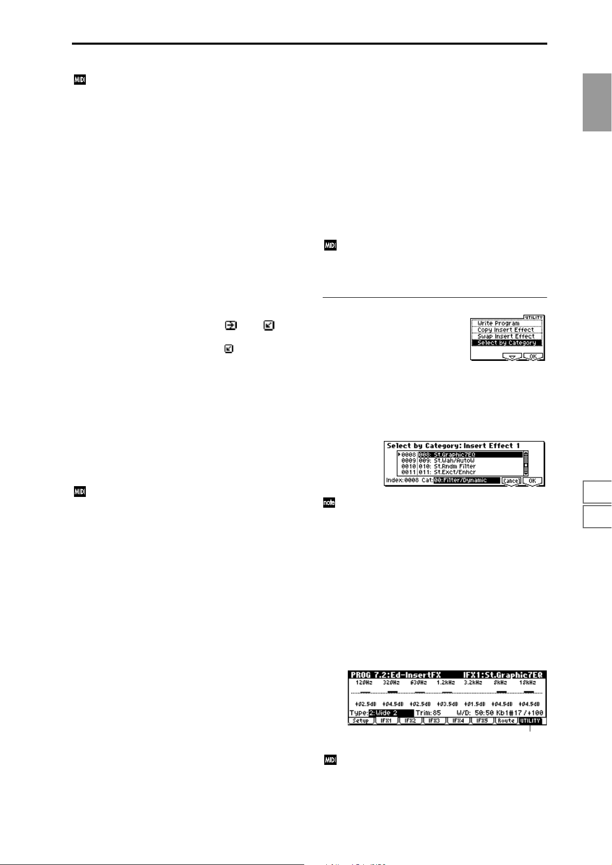
Separately from this setting, you can use control change
#92 to turn off all insert effects together. A value of 0
will be off, and a value of 1–127 will be the original setting. This message is received on the global MIDI channel specified by “MIDI Channel” (GLOBAL 2.1–1a).
Insert Effect 1, 5 [000...089: name]
Insert Effect 2, 3, 4 [000...102: name]
Indicates the type of each insert effect.
For “Insert Effect 1” and “Insert Effect 5” you can select from
90 types of effect: 000: No Effect – 089: Reverb-Gate. Double-size effects cannot be used.
For “Insert Effect 2,” “Insert Effect 3” and “Insert Effect 4”
you can select from 103 types of effect: 000: No Effect – 102:
Hold Delay.
If you select a double-size effect, the next insert effect will be
unavailable for use. For example if you select a double-size
effect for IFX2, IFX3 cannot be used. A maximum of two
double-size effects can be used (normal size for IFX1, double
size for IFX2 and IFX4) (
These effects can also be selected by category in Utility
“Select by Category” (7.2–1b).
☞p.160).
Chain [ (Off), (On)]
Indicates “chain” on/off for each insert effect.
For example if “Chain” for IFX1 is set to (On), IFX1 and
IFX2 will be connected in series. If “BUS Select” (7.1–1a) is
set to IFX1, IFX1 and IFX2 will be inserted in series.
A maximum of five insert effects (IFX1–IFX5) can be
inserted in series. When effects are chained, the “Pan
(CC#8),” “BUS Select,” “S1 (Send1(MFX1))” and “S2
(Send2(MFX2))” settings that follow the last IFX in the chain
will be used.
Pan(CC#8) (Post IFX Pan CC#8) [L000...C064...R127]
Sets the pan after the sound has passed through the insert
effect. This setting is valid only when the following “BUS
Select” is set to L/R (
CC#8 will control.
☞p.162).
BUS Select [L/R, 1, 2, 1/2, Off]
Specifies the bus to which the sound will be sent after passing through the insert effect. Normally you will set this to L/
R. If you wish to output to AUDIO OUTPUT (INDIVIDUAL), set this to 1, 2 or 1/2. The Off setting is used when
you wish to use “S1 (Send1(MFX1))” and “S2
(Send2(MFX2))” and in addition connect to the master
effects in series.
S1 (Send1 (MFX1)) [000...127]
S2 (Send2 (MFX2)) [000...127]
Sets the send levels to the master effects 1 and 2 for the
sound that has passed through the insert effect. These settings are valid when “BUS Select” (7.1–1a) has been set to L/
R or Off.
Control change CC#93 will control the Send 1 level, and
control change CC#91 will control the Send 2 level.
These messages are received on the global MIDI channel specified by “MIDI Channel” (GLOBAL 2.1–1a).
■ 7.2–1b: UTILITY
☞ “Write Program” (1.1–1c), “Copy Insert Effect,” “Swap
Insert Effect” (7.1–1c)
Select by Category
Indicates insert effects by category.
For the procedure, refer to “Select by Category” (
This command can be used when selecting “Insert
Effect 1”–”Insert Effect 5.”
☞p.2).
PROG
1.1
2.12.22.33.14.14.25.15.25.36.16.26.36.47.17.27.3
7.2–2: IFX 1 (Insert Effect1)
7.2–3: IFX 2 (Insert Effect2)
7.2–4: IFX 3 (Insert Effect3)
7.2–5: IFX 4 (Insert Effect4)
7.2–6: IFX 5 (Insert Effect5)
Here you can set the effect parameters for the IFX 1/2/3/4/
5 that were selected in the Setup page (
Effect dynamic modulation (Dmod) is controlled on the
global MIDI channel “MIDI Channel” (GLOBAL 2.1–
1a). (
☞p.227 “Dynamic Modulation Source (D.mod)”)
☞p.168).
7.2–2a
39
Page 50
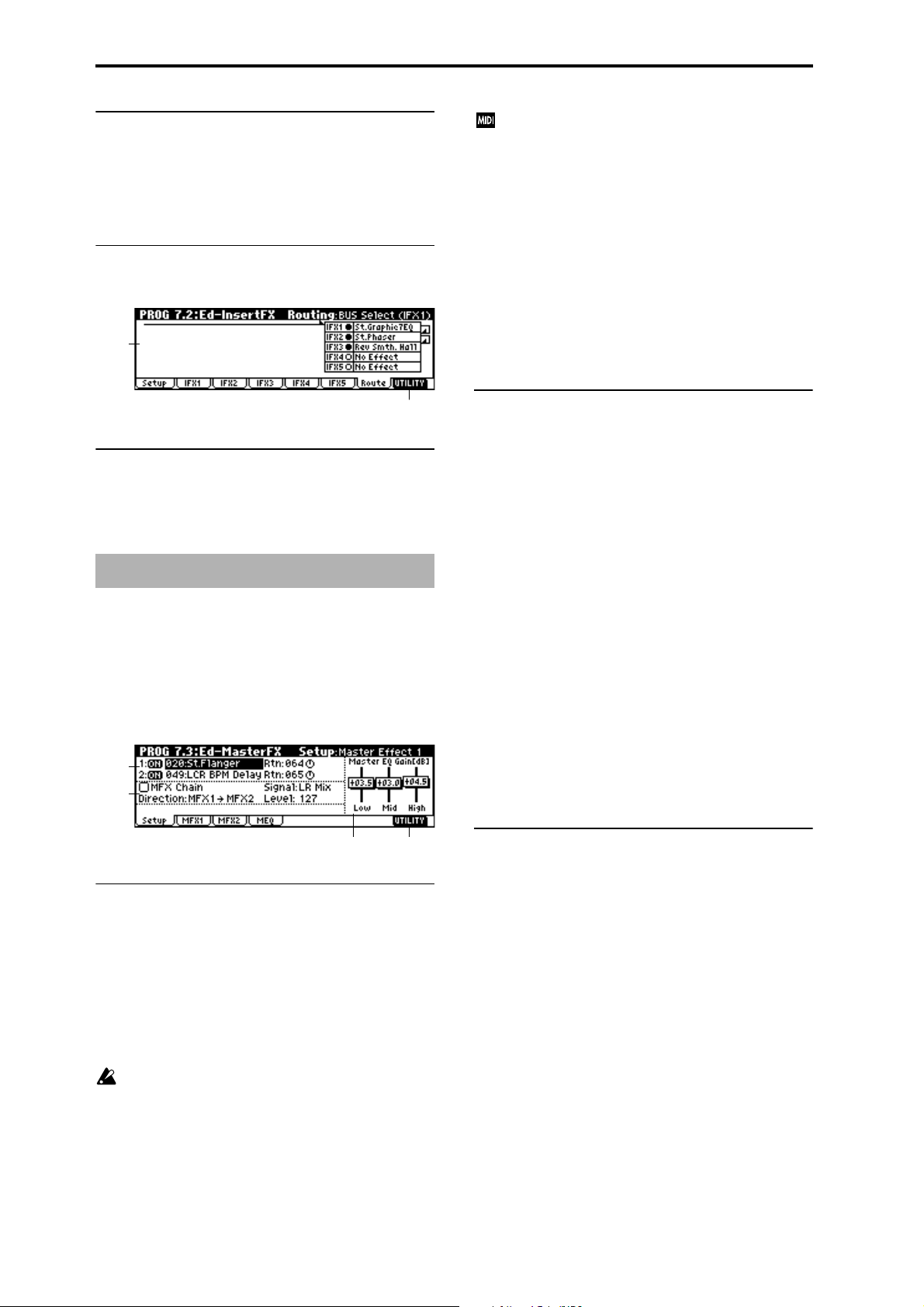
■ 7.2–2(...6)a: UTILITY
☞ “Write Program” (1.1–1c)
7.2–7: Routing (Routing)
7.2–7a: Routing
This shows the status of the insert effect settings. (☞7.1–2a)
7.2–7a
Separately from this setting, you can use CC#94 to
switch master effect 1 on/off, CC#95 to switch master
effect 2 on/off. A value of 0 will be off, and a value of 1–
127 will be the original setting. This is controlled on the
global MIDI channel “MIDI Channel” (GLOBAL 2.1–
1a).
Master Effect 1, 2 [000...089: name]
Indicates the effect type for master effect 1, 2. You can select
from 90 types of effect: 000: No Effect–089: Reverb-Gate.
(Double-size effects cannot be selected.) If 000: No Effect is
selected, the output from the master effect will be muted.
Rtn 1, 2 (Return 1, 2) [000...127]
Adjusts the return levels from the master effects to the L/R
bus (main output L/MONO, R).
7.2–7b
■ 7.2–1b: UTILITY
☞ “Write Program” (1.1–1c), “Copy Insert Effect,” “Swap
Insert Effect” (7.1–1c)
PROG 7.3: Ed–MasterFX
☞ For details on insertion effects, refer to p.159 “7. Effect
Guide.”
7.3–1: Setup
Here you can select the master effect types, switch them on/
off, specify chaining, and set the master EQ.
7.3–1a
7.3–1b
7.3–1d7.3–1c
7.3–1a: Master Effect Setup
The master effects do not output the direct sound (Dry). The
return level (“Rtn 1, 2”) sends the effect sound (Wet ) to the L
and R bus, and this is mixed with the direct sound (“BUS
Select” L/R: 7.1–1a, 7.2–1a).
The master effects are monaural input. The sound that is
panned to L and R after passing through the oscillator and
insert effects is mixed to a monaural signal as adjusted by
the “S1 (Send1 (MFX1))” and “S2 (Send2 (MFX2))” levels,
and input to the master effects.
The master effects are mono-in stereo-out. Even when
a stereo-input type effect is selected, the input will be
monaural.
7.3–1b: Chain
MFX Chain [Off, On]
On (checked): Chain (series connection) will be turned on
for MFX1 and MFX2. (
☞p.165)
Direction (Chain Direction)
[MFX1→MFX2, MFX2→MFX1]
Specifies the direction of the connection when MFX1 and
MFX2 are chained.
MFX1→MFX2: Connect from MFX1 to MFX2.
MFX2→MFX1: Connect from MFX2 to MFX1.
Signal (Chain Signal) [LR Mix, L Only, R Only]
When chain is On, this parameter specifies how the stereo
output signal of the first master effect will be connected to
the input (mono) of the next master effect.
L/R Mix: The stereo output L/R of the first master effect will
be mixed before being input to the next master effect.
L Only, R Only: Only the left or right channel of the output
will be input to the next master effect.
Level (Chain Level) [000...127]
Sets the send level from the first master effect to the next
master effect when chain is turned on.
7.3–1c: Master EQ Gain [dB]
Sets the gain for the three-band EQ located immediately
before the sound of the L/R bus is sent from the AUDIO
OUTPUT (MAIN OUT) L/MONO and R jacks. This is
linked with the various “Gain” parameters of Master EQ
(7.3–4).
Low [–18.0...+18.0]
Mid [–18.0...+18.0]
High [–18.0...+18.0]
The cutoff frequency for “Low,” “Mid” and “High” and the
“Q” of “Mid” can be adjusted in the MEQ page. These set-
tings are in “dB” units.
MFX1 On/Off, MFX2 On/Off [Off, ON]
Switches master effect 1, 2 on/off. When off, the output will
be muted.
40
Page 51
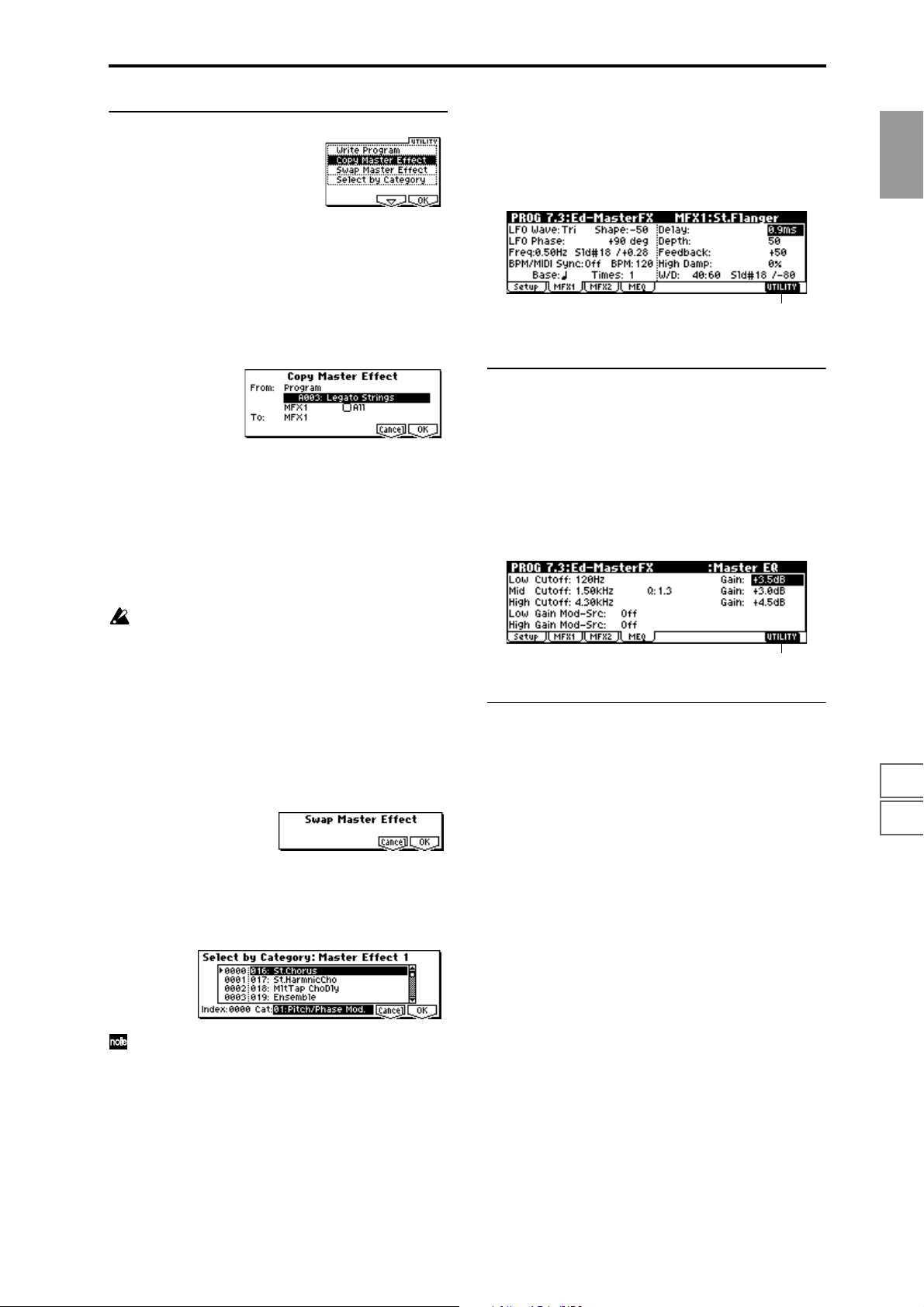
■ 7.3–1d: UTILITY
7.3–2: MFX 1 (Master Effect1)
7.3–3: MFX 2 (Master Effect2)
Indicates effect parameter settings for the MFX1 and 2
effects that were selected in the Setup page (
☞p.168).
PROG
☞ “Write Program” (1.1–1c)
For details on how to select the desired utility function, refer
to “PROG 1.1–1c: UTILITY.”
Copy Master Effect
This command lets you copy any desired effect settings from
Program, Combination, Song or Song Play modes.
1 Select “Copy Master Effect” to access the dialog box.
2 In “From,” select the copy source mode, bank, and num-
ber.
You can use the Bank [A]–[G] keys to select the bank.
3 Select the effect that you wish to copy. If you select MFX
1 or 2, “Rtn (Return)” (return level) will be copied at the
same time. If you select Master EQ, only the master EQ
settings will be copied. You can also copy from an insert
effect. If you check “All,” all settings of the master effects
and master EQ will be copied.
If you copy from an insert effect the result may not be
identical, due to differences in routing and level settings.
4 In “To , ” select the copy destination master effect.
5 To execute the Copy Master Effect command, press the
[F8] (“OK”) key. To cancel, press the [F7] (“Cancel”) key.
Swap Master Effect
This command swaps (exchanges) the settings of MFX1 and
MFX2.
1 Select “Swap Master Effect” to access the dialog box.
7.3–2a
(
☞p.227 “Dynamic Modulation Source (D.mod)”)
■ 7.3–2(3)a: UTILITY
☞ “Write Program” (1.1–1c)
7.3–4: MEQ (Master EQ)
The master EQ is a three-band stereo EQ. It is used to adjust
the overall tonality of the sound immediately before the L/R
bus is output to the AUDIO OUTPUT (MAIN OUT) L/
MONO and R jacks (
■ 7.3–4a: UTILITY
☞ “Write Program” (1.1–1c)
☞p.220).
7.3–4a
1.1
2.12.22.33.14.14.25.15.25.36.16.26.36.47.17.27.3
2 To execute the Swap Master Effect command, press the
[F8] (“OK”) key. To cancel, press the [F7] (“Cancel”) key.
Select by Category
Selects master effects by category. (☞p.2)
This command can be used when selecting “Master
Effect 1,” ”Master Effect 2.”
41
Page 52

42
Page 53
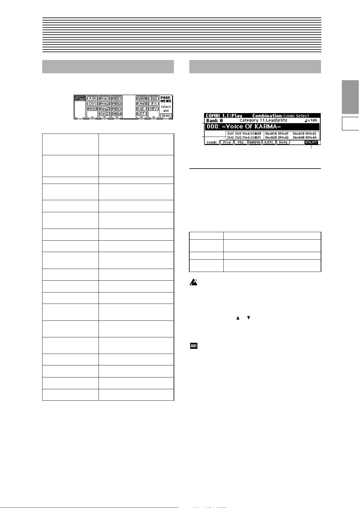
2. Combination mode
COMBI PAGE MENU
For details on how to select pages in Combination mode,
refer to p.1.
Play 1.1: Play Select and play combinations. Select a
P/M 2.1: Ed-Prog/Mix Select a program for each timbre, and
Ctrl 2.2: Ed-Ctrl Controller settings. (
MOSS 2.3: Ed-MOSS Displayed if the separately sold EXB-
Prm1 3.1: Ed-Param1 MIDI, OSC, and Pitch settings for each
Prm2 3.2: Ed-Param2 Enable timbre sounding by KARMA
KeyZ 3.3: Ed-Key Zone Key zone settings for each timbre.
VelZ 3.4: Ed-Vel Zone Velocity zone settings for each timbre.
MIDI1 4.1: Ed-MIDI Filter1 MIDI message transmission/reception
MIDI2 4.2: Ed-MIDI Filter 2 Filter settings such as JS and Ribbon
MIDI3 4.3: Ed-MIDI Filter 3 Filter settings; Real-time Control Knob
MIDI4 4.4: Ed-MIDI Filter 4 Filter settings; SW, Other Ctrl Change
KARM 6.1: Ed-KARMA KARMA GE selection and settings,
K Mdl 6.2: Ed-KARMA Mdl Module parameter settings (transpose,
K GE 6.3: Ed-KARMA GE GE parameter settings and assign-
K RT 6.4: Ed-KARMA RT KARMA RT parameters, Dynamic MIDI
BUS 7.1: Ed-BUS Bus and master effect send level set-
IFX 7.2: Ed-InsertFX Insert effect routing, selection, and set-
MFX 7.3: Ed-MasterFX Master effect selection and settings.
program for each timbre, and set status, pan, and level. KARMA GE selection, Run/Solo settings. (
set pan and level. (Same as the 1.1:
Play parameters; can be edited from
either page.) (
MOSS option is installed. Set EXBMOSS parameters. (
timbre. (
ON/OFF, delay and scale settings for
each timbre. (
☞p.52)
(
☞p.53)
(
filter settings for each timbre, such as
Prog Change and After Touch. (
Ctrl. (
☞p.55)
(
☞p.56)
(
mixer channel, key zone parameters,
MIDI filter settings. (
range of generated phrase, trigger etc.)
☞p.61)
(
ments to KARMA real-time Controls.
☞p.62)
(
settings. (
tings for each timbre. (
tings. (
Master EQ settings. (
☞p.48)
☞p.49)
☞p.51)
☞p.55)
☞p.63)
☞p.66)
☞p.43)
☞p.49)
☞p.49)
☞p.54)
☞p.57)
☞p.65)
☞p.67)
COMBI 1.1: Play
In this display page you can select and play Combinations.
1.1–1: Combi (Combination)
1.1–1a
1.1–1b
1.1–1c
1.1–1a: Bank, Combi Select, Category, Cat.Hold,
10’s Hold, (Tempo)
Bank (Bank Select) [Bank A…F]
This is the Combination bank display.
Use the front panel BANK [A]–[F] keys to select the bank.
On this instrument, there are a total of 768 combination programs in four rewritable banks (A, B, C, D, E, F), each containing 128 combinations.
Bank A, B Preloaded combinations
Bank C, D EXB-PCM series combinations, User combina-
Bank E Preloaded combinations
Bank F User combinations, EXB-PCM series combina-
If you have selected the “Program Select” (1.1–2c) edit
cell for a timbre 1–8 in the Prog page, Bank [A]–[G] will
switch the program banks for timbres 1–8.
Combi Select (Combination Select) [0...127: name]
Here you can select a combination. Select this parameter,
and use the VALUE [ ], [ ] keys, numeric keys [0]–[9], or
the [VALUE] dial to select a combination. You can also select
combinations by category, or using “10’s Hold.” (
”Select by Category,” “Cat.HOLD,” “10’s HOLD”)
You can select programs by transmitting MIDI program
changes from a connected external MIDI device, or by
using a foot switch. (
BAL 6.1–1a,
tions
tions
☞p.2
☞p.145 “Foot SW Assign” (GLO-
☞p.232 “Foot Switch Assign List”)
COMBI
1.1
2.12.22.33.13.23.33.44.14.24.34.46.16.26.36.47.17.27.3
43
Page 54
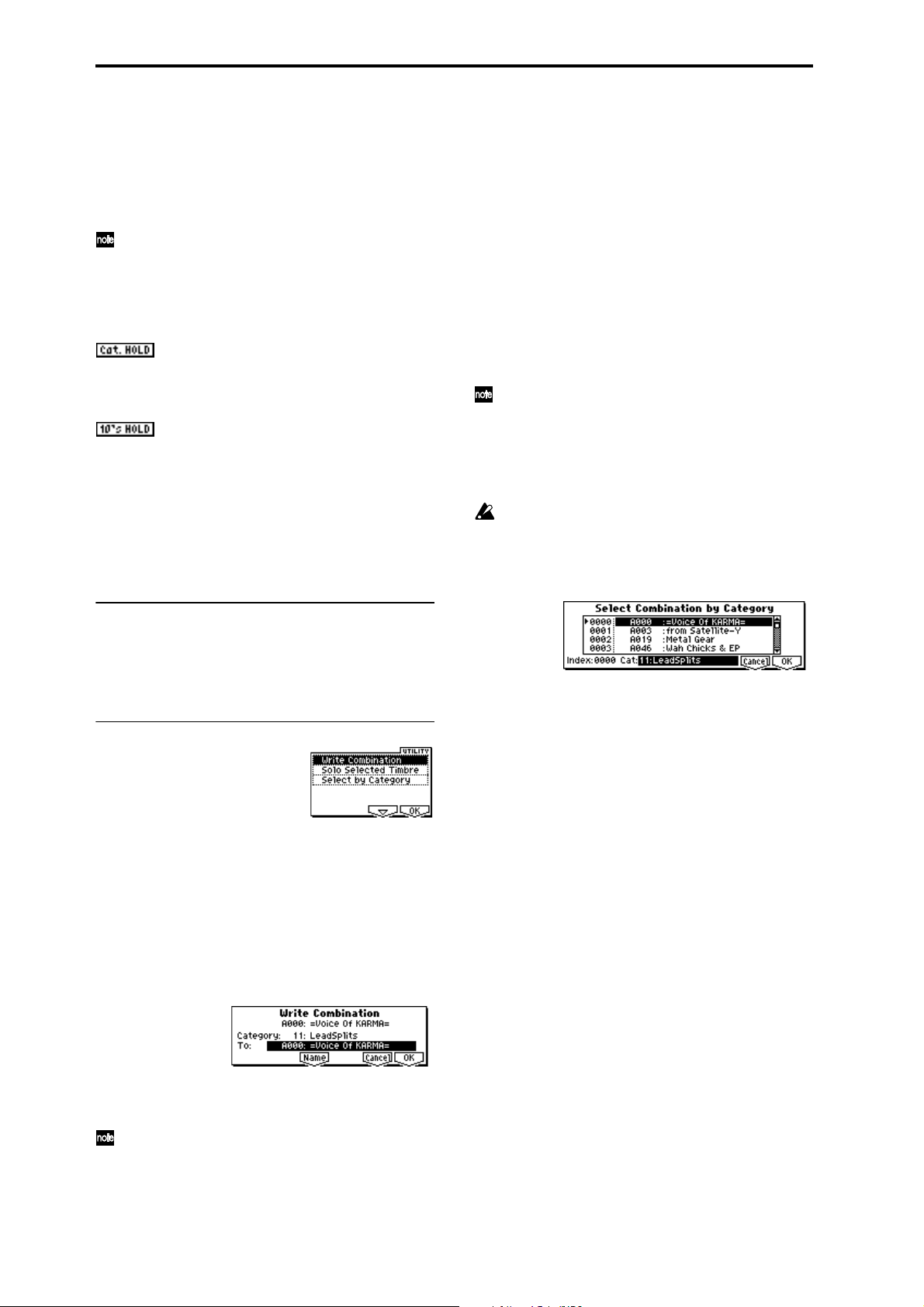
Category [00...15: name]
This is the combination category display.
All combinations are organized into sixteen categories. You
can select a category, and then select from combinations that
belong to that category.
To select combinations by category, use “Cat.HOLD” and
Utility “Select by Category.” (
To specify the category for a combination, use Utility
“Write Combination” (1.1–1c). To modify a category
name, use “Category Name Comb. 00–07, 08–15”
(GLOBAL 4.1–3/4).
☞PROG 1.1–1a)
Cat.HOLD
Press the [./HOLD] key and the display will indicate
. The category will be held (fixed). (
1a)
☞PROG 1.1–
10’s HOLD
When you press the [./HOLD] key, the display will indicate
, and the first digit of the combination number
will be fixed. (
☞PROG 1.1–1a)
(Tempo) [040...240, EXT]
Sets the tempo of the KARMA function. This can be adjusted
by [TEMPO] knob.
EXT will be displayed if “MIDI Clock” (GLOBAL 2.1–1a) is
set to External, and the KARMA function will synchronize
to the MIDI clock received from an external MIDI device.
This parameter can also be set from 6.1: Ed-KARMA.
Solo Selected Timbre
The Solo function will alternately be switched on/off each
time you select “Solo Selected Timbre.”
1 From the utility menu, choose “Solo Selected Timbre,”
and press the [F8] (“OK”) key to execute the command.
When you execute this, a check mark will appear at the
left of the “Solo Selected Timbre” menu item, and the
Solo function will be on.
2 In pages that show parameters for an individual timbre,
you can select a timbre to Solo (in 1.1: Play, Prog page
“Program Select,” etc.) so that only that timbre will
sound and the other timbres will be muted. The “Selected
Timbre Information” (1.1–2d) in each page will indicate
“Solo.”
To solo a different timbre, select a parameter of the timbre that you wish to solo.
You can move to timbres “T1”–“T8” by holding down
the [TIMBRE/TRACK] key and pressing one of the
[F1](T1/T9)–[F8](T8/T16) keys.
3 To defeat the Solo function, choose “Solo Selected Tim-
bre” from the utility menu once again, and press the [F8]
(“OK”) key to cancel it.
If a timbre that is muted by the Solo function has been
set to a “Status” (3.1–1a) of EXT or EX2, MIDI note-on/
off messages will not be transmitted by that timbre.
Select by Category
Selects a combination by category. (☞p.2)
1.1–1b: Combination Information
This displays information for the selected combination. The
functions assigned to [SW1], [SW2], and real-time CONTROLS B mode [ASSIGNABLE 1–4] knobs will be displayed.
■ 1.1–1c: UTILITY
For details on how to select the desired utility function, refer
to “PROG 1.1–1c: UTILITY.”
Write Combination
This command writes an edited combination into this
instrument’s internal memory. Be sure to write any combination that you wish to keep. If the power is turned off or a
different combination selected before you write an edited
combination, your edits cannot be recovered.
For the procedure, refer to “Write Program” (PROG 1.1–1c).
If you use “Category” to specify a category for the combination that you are writing, you will be able to select it by category when selecting combinations in COMBI 1.1: Play.
When you press the [REC/WRITE] key, the “Update
Combination” dialog box will appear. Here also you
can write to the currently selected combination.
44
Page 55

1.1–2: Prog (Timbre Program)
Indicates the program that will be used by each timbre.
1.1–2a
1.1–2b
1.1–2c
1.1–2d
1.1–2e
1.1–2a: Bank, Combi Select, Cat.Hold, 10’s Hold,
(Tempo)
Bank [Bank A…Bank F]
Combi Select (Combination Select) [0…127: name]
Cat. (Cat. HOLD)
10’s (10’s HOLD)
(Tempo) [040...240, EXT]
In the same way as in the Combi page, select a combination
and set the tempo of the KARMA function. (
1.1–2b: Timbre Number & Category
☞1.1–1a)
If bank select and program change messages are
received on a MIDI channel that matches the MIDI
channel of a timbre whose “Status” (3.1–1a) is INT, the
program of that timbre will change. However if the
MIDI channel of the incoming message matches the
global MIDI channel “MIDI Channel,” then the combination will change.
If you do not want the combination to change, you can
either change the global MIDI channel so that it does
not match the channel on which the program change
messages are being received, or you can uncheck
“Combi (Combi Change)” (GLOBAL 2.1–1b). Alternately, you can uncheck “Bank (Bank Change)” (GLOBAL 2.1–1b) so that only the program number will
change and the bank will remain the same.
If you wish to change a program without changing the
combination, you can also set “Program Change” (4.1–
1a) so that the program will change on certain timbres
but not on others.
Program Name
This displays part of the program name selected for the timbre. In the case of the GM2 variation bank or the GM2
drums bank, the variation bank (1)–(9) or drums bank (d)
will be indicated.
COMBI
1.1
2.12.22.33.13.23.33.44.14.24.34.46.16.26.36.47.17.27.3
Timbre Number & Category 1...8
This displays the timbre number and an abbreviated category name.
1.1–2c: Program Select, Program Name
Program Select [A000...g128]
Indicates the program that will be used by each timbre.
When “Program Select” is selected, you can use the Bank
[A]–[G] key, numeric keys [0]–[9], VALUE controller to
select a program.
“Program Select” settings can also be made in the Prog page
of 2.1: Ed-Prog/Mix.
You can also use Utility “Select by Category” to select programs by category.
You can move to timbres “T1”–“T8” by holding down
the [TIMBRE/TRACK] key and pressing one of the
[F1](T1/T9)–[F8](T8/T16) keys.
Bank F can be selected if you have installed the separately sold EXB-MOSS option. When installed, the 128
special EXB-MOSS programs will be available.
When you select a combination on this instrument, a
MIDI program change for the selected combination
number will be transmitted on the global MIDI channel
“MIDI Channel” (GLOBAL 2.1–1a). At the same time,
bank select, program change, and volume (CC#7) messages will be transmitted on the MIDI channel specified
for each timbre that is set to “Status” (3.1–1a) of EXT or
EX2. However, these messages will not be transmitted
for timbres that are set to the same MIDI channel as the
global MIDI channel. In this case, EX2 timbres will
show the “Program Select” Bank as “–”, and will transmit the bank number that was specified in “Bank (EX2)
MSB”and “Bank (EX2) LSB” (3.1–1a).
MIDI messages transmitted when you operate this
instrument are transmitted on the global MIDI channel.
At the same time, timbres whose “Status” is EXT or EX2
will transmit the same messages on their own MIDI
channel.
1.1–2d: Selected Timbre Information
This shows information on the timbre (1–8) that is currently
selected for editing.
Timbre No.: Bank No., Prog No.: and name
This shows the timbre number, and the program bank, number and name selected for that timbre.
Status (INT, Off, EXT, EX2)
This shows the MIDI and internal tone generator status for
each track.
Ch (01...16, Gch)
This shows the MIDI channel number specified for the timbre.
■ 1.1–2e: UTILITY
☞ “Write Combination,” “Solo Selected Timbre” (1.1–1c)
For details on how to select the desired utility function, refer
to “PROG 1.1–1c: UTILITY.”
45
Page 56
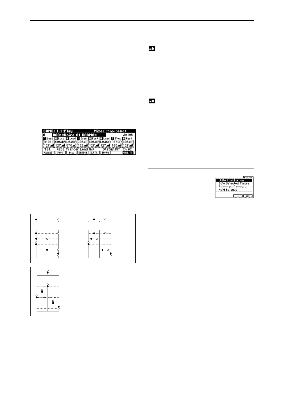
Select by Category
Combinations or the programs used by each timbre can be
selected by category.
If you have selected “Combi Select,” selecting Utility
“Select by Category” will access the Select Combination by
Category dialog box, allowing you to select a combination
by category. (
☞p.44)
If you have selected “Program Select,” selecting Utility
“Select by Category” will access the Select Program by Cate-
gory (Timbre) dialog box, allowing you to select a program
for each timbre by category.
For the procedure of selecting by category, refer to p.2.
1.1–3: Mix (Mixer)
Here you can set the pan and volume for each timbre 1–8.
1.1–3a
1.1–3b
RND: The oscillator pan will change randomly at each noteon.
If “Status” (3.1–1a) has been set to INT, MIDI control
change #10 (panpot) messages can be received to control the setting. CC#10 values of 0 or 1 will place the
sound at far left, 64 at center, and 127 at far right.
Pan can be controlled by messages received on the
“MIDI Channel” (3.1–1a).
Volume [000...127]
Adjusts the volume of each timbre 1–8. (This parameter can
also be set from the Mixer page of 2.1: Ed-Prog/Mix.)
The volume of each timbre is determined by multiplying this volume value with the MIDI volume (CC#7)
and expression (CC#11). If “Status” (3.1–1a) has been
set to INT, incoming MIDI CC#7 or CC#11 messages
will control the volume of a timbre. (However these
messages will not affect the setting of this parameter.)
If “Status” is EXT or EX2, the value of this parameter
will be transmitted as MIDI CC#7 when the combination is changed. However this will not be transmitted
by a timbre that is set to the same MIDI channel as the
global MIDI channel. This message is transmitted on
the “MIDI Channel” (3.1–1a) specified for each timbre.
1.1–3a: Pan, Volume
Pan [RND, L001...C064...R127]
Sets the pan for each timbre 1–8. (This parameter can also be
set from the Mixer page of 2.1: Ed-Prog/Mix.)
L001...C064...R127: A setting of L001 is far left and R127 is
far right. A setting of C064 will reproduce the pan setting
that was made for the oscillator in Program mode.
OSC1
Left
Left
OSC1
Left
Left
Center
Center
Center
Center
OSC2
OSC1: Amp1 Pan=L001
OSC2: Amp2 Pan=R127
Right
Pan (CC#10)
C064
L032
L001
R096
R127
Right
OSC2
OSC1: Amp1 Pan=C064
OSC2: Amp2 Pan=C064
Right
Pan (CC#10)
C064
L032
L001
R096
R127
Right
OSC1: Amp1 Pan=L032
Left
Center
Left
Center
OSC2: Amp2 Pan=R096
Right
Pan (CC#10)
C064
L032
L001
R096
R127
Right
■ 1.1–3b: UTILITY
☞ “Write Combination,” “Solo Selected Timbre,” “Select by
Category” (1.1–1c, PROG 1.1–1a)
For details on how to select the desired utility function, refer
to “PROG 1.1–1c: UTILITY.”
Hold Balance
Adjusts the volume of the Combi while preserving the volume balance between timbres 1–8.
Selects the “Volume” of any timbre, select “Hold Balance”
from the Utility menu, and press the [F8] (“OK”) key. A
check mark will appear at the left of “Hold Balance.” (The
upper left of the LCD screen will indicate [Hold Bal.]) In this
state, adjusting any “Volume” value will simultaneously
change the volume of the other timbres as well, while preserving the volume balance between timbres 1–8.
If a mono-type insertion effect is inserted, the setting you
make here will be ignored. In this case, the “Pan (CC#8)”
parameter in 7.2: Ed–InsertFX, Setup page will adjust the
panning of the sound after the insertion effect (
☞p.162 “3.
Mixer”).
46
Page 57
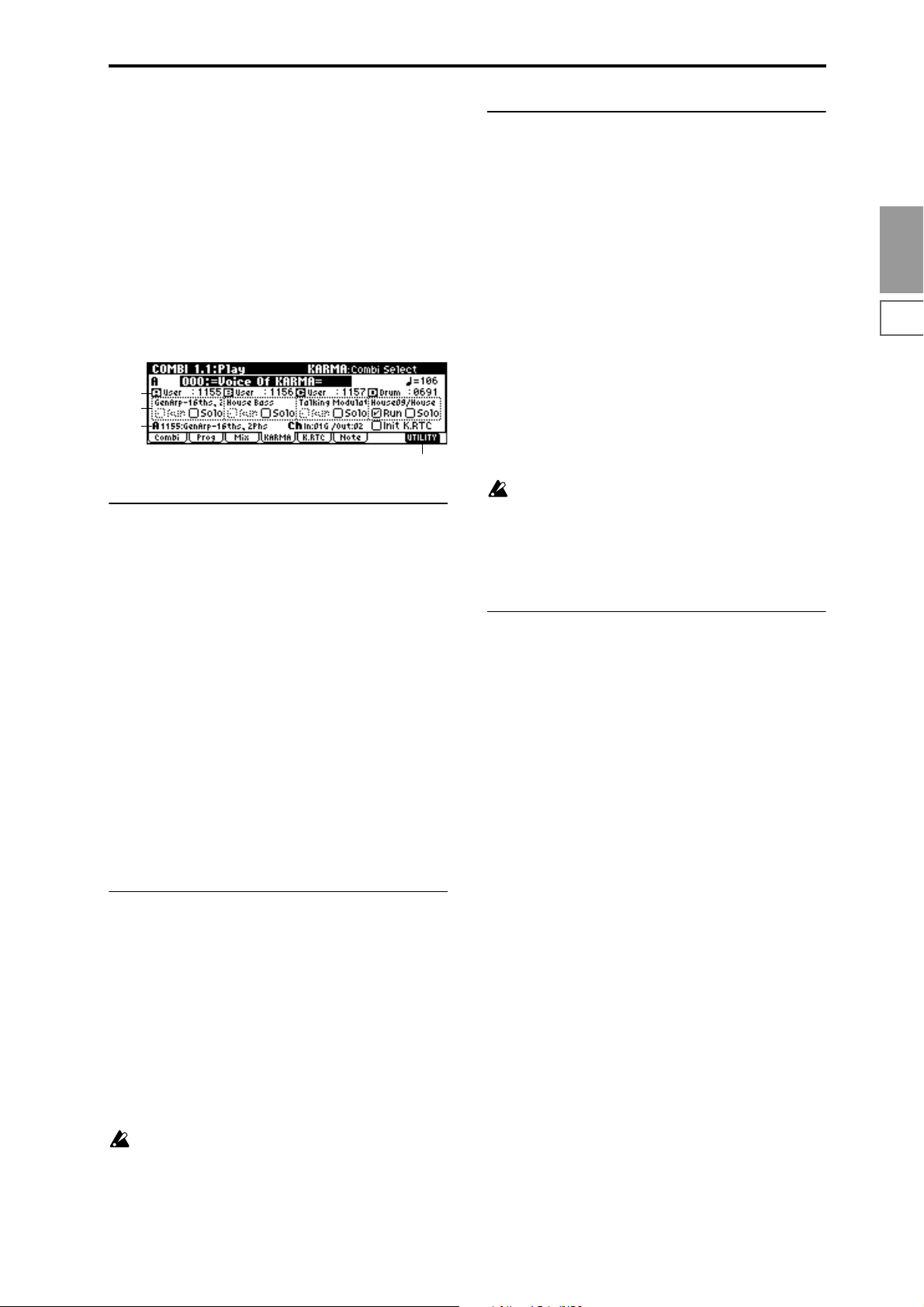
1.1-4: KARMA
Here you can make KARMA settings that will be used by
the combination. A combination allows up to four KARMA
modules to operate simultaneously. Here you can select the
GE (Generated Effect) that will be used by each KARMA
module, and turn each KARMA module on/off (“Run,”
“Solo” control). Other settings are made in the COMBI 6.1,
6.2, 6.3, and 6.4 pages.
The KARMA function is turned on/off by the KARMA realtime Controls [ON/OFF] key. The settings of the KARMA
real-time Controls knobs [1]–[8], switches [1]/[2], [LATCH],
and [SCENE] key, and the note settings/velocity of CHORD
TRIGGER [1]–[4] keys can be saved independently for each
combination.
1.1–4a
1.1–4b
1.1–4c
1.1–4d
1.1–4a: GE Category, GE Select
The phrases and patterns produced by a KARMA module
are generated by a GE (Generated Effect). Based on input
note data from the keyboard, the GE creates phrases and
patterns using numerous internal parameter settings to control the development of the note data, the rhythm, the chord
structure, the velocity etc. MIDI control changes and pitch
bend etc. can also be generated in synchronization with the
phrase or pattern. In this way you can produce phrases and
patterns in which the GE freely varies the tone or pitch.
The GE can be selected for each KARMA module. In Combination mode, you can use four KARMA modules (modules
[A], [B], [C], and [D]).
GE Category [00: name...]
This displays the category of the GE selected for the
KARMA module. (
“GE Category”)
☞p.5 PROG 1.1–3a: KARMA GE Setup,
1.1–4c: Selected GE Information, Init K.RTC
This displays information on the KARMA module [A], [B],
[C], or [D] that is currently being edited.
GE No., GE Name
This displays the GE number and GE name.
MIDI In/Out Ch
This displays the MIDI Input Ch (input channel) and MIDI
Output Ch (output channel) of the KARMA module. These
settings are made in 6.1–2: MIDI I/O, “Input Channel,”
“Output Channel” (6.1–2a).
Init K.RTC (KARMA real-time Controls–Use GE’s Value)
[Off, On]
Specify whether the settings of the KARMA real-time Controls knobs [1]–[8] and switches [1]/[2] will be initialized
when you select a GE. This allows you to hear the phrase or
pattern generated by the GE in its original state. Normally
you will leave this On when selecting a GE.
☞ p.5 PROG 1.1–3a: KARMA GE Setup, “Init K.RTC”
KARMA real-time Controls knobs [1]–[8] and switches
[1]/[2] of the applicable KARMA module that are not
assigned to GE parameters will not be initialized (
1a “Asgn”). However if they are simultaneously
assigned to GE parameters for multiple KARMA modules, they will be initialized. This may cause the state of
another KARMA module to change.
■ 1.1–4d: UTILITY
☞ “Write Combination,” “Solo Selected Timbre” (1.1–1c)
☞6.3–
Select by Category
(Select Combination by Category/Select by Category:
GE)
If “Combi Select” (1.1–2a) is selected, you can select combinations by category. (
If “GE Select” (1.1–4a) is selected, you can select a GE by category.
For the procedure, refer to “Select by Category” (
☞p.44)
☞p.2).
COMBI
1.1
2.12.22.33.13.23.33.44.14.24.34.46.16.26.36.47.17.27.3
GE Select [0000: Arp Model 1 Up/Dn...]
Select the GE. (☞p.5 PROG 1.1–3a: KARMA GE Setup, “GE
Select”)
1.1–4b: GE Name, Run Check Box, Solo Check Box
GE Name
This displays the name of the GE selected in “GE Select.”
Run Check Box [Off, On]
KARMA modules that are On (checked) will operate.
Solo Check Box [Off, On]
Check this when you wish to audition only a specific
KARMA module while KARMA is operating.
Only the KARMA module that is On (checked) will operate.
Even if “Run” is Off (unchecked), the module that is On
(checked) here will operate.
This setting will be cleared when you reselect the combination. It will not be remembered when you write the
combination.
47
Page 58

1.1–5: K.RTC (KARMA RTC)
1.1–5a
1.1–5b
COMBI 2.1: Ed–Prog/Mixer
2.1–1: Prog (Timbre Program)
Indicates the bank and program for each timbre 1–8. These
parameters can also be set from the 1.1: Play, Prog page.
1.1–5a: RT Knob/SW Name
This displays the name of the KARMA real-time Controls
knobs [1]–[8] and switches [1]/[2], and the knob or switch
settings that are written in the combination.
The [----] portion preceding the name of the knob or switch
shows the abbreviated name of the category of the program
sounded by the timbre that is played by the KARMA module controlled by operations of knobs [1]–[8] and switches
[1]/[2]. If there are multiple timbres with programs of differing categories, this will indicate [MLTI].
The name can be selected in COMBI 6.4–4/5: Ed-KARMA
RT, Name1/2 page.
☞p.6 PROG 1.1–4a: RT Knob/SW Name
■ 1.1–5b: UTILITY
☞ “Write Combination,” “Solo Selected Timbre,” “Select by
Category” (1.1–1c)
1.1–6: Note (Note Activity)
1.1–6a
2.1–1a
2.1–1b
2.1–1a: Program Select, Program Name
Program Select
Indicates the program that will be used by each timbre.
(
☞1.1–2c)
Program Name
This displays part of the program name selected for each
timbre. (
■ 2.1–1b: UTILITY
☞ “Write Combination,” “Solo Selected Timbre” (1.1–1c),
☞1.1–2c)
“Select by Category”: Select Program by Category (Timbre) (1.1–2e)
2.1–2: Mix (Mixer)
Specifies the pan and volume for each timbre 1–8. These
parameters can also be set from the 1.1: Play, Mixer page.
1.1–6b
1.1–6a: Note Activity Display, Chord Name
Note Activity Display A, B, C, D
This is a real-time display of the note on/off status generated by each KARMA module (modules [A], [B], [C], and
[D]).
The key zone settings of the four KARMA modules are displayed as a solid line. (
☞p.59 COMBI 6.1–3: Key Z)
Chord Name A, B, C, D
This shows the name of the chord detected by each KARMA
module.
Chord detection is affected by the key zone (COMBI
6.1-2a: Ed-KARMA Key Zone) and “Transpose”
(COMBI 6.2-1a: Module Parameter) of each KARMA
module, and by the “Dynamic MIDI Destination”
(COMBI 6.4-3a/b/c/d) “Chord Scan” and “Smart
Scan” settings.
■ 1.1–6b: UTILITY
☞ “Write Combination,” “Solo Selected Timbre,” “Select by
Category” (1.1–1c)
2.1–2a
2.1–2b
2.1–2a: Pan, Volume
Pan
Sets the pan of each timbre 1–8. (☞1.1–3a)
Volume
Sets the volume of each timbre 1–8. (☞1.1–3a)
■ 2.1–1b: UTILITY
☞ “Write Combination,” “Solo Selected Timbre” (1.1–1c)
48
Page 59

COMBI 2.2: Ed–Ctrl
Here you can set the Combination mode functions of the Bmode functions of real-time CONTROLS knobs [1]–[4], and
[SW1] key, [SW2] key.
2.2–1: Ctrls (Controls)
2.2–1a
COMBI 3.1: Ed–Param1
3.1–1: MIDI
Here you can make MIDI settings for each timbre.
3.1–1a
3.1–1b
COMBI
1.1
2.2–1b
2.2–1c
2.2–1a: Knob B Assign
These settings assign functions (mainly various control
changes) to the “B” mode of the real-time CONTROLS
knobs [1]–[4] (
List”).
The functions you specify here will be controlled when you
operate the real-time CONTROLS knobs [1]–[4] in “B”
mode.
Since the real-time CONTROLS knob [1]–[4] function of the
B mode assignments made for the program assigned to each
timbre are not valid for the combination, they must be
newly set by these parameters.
☞p.231 “Realtime Control Knobs B Assign
Knob1–B (Knob1–B Assign) [Off...MIDI CC#95]
Knob2–B (Knob2–B Assign) [Off...MIDI CC#95]
Knob3–B (Knob3–B Assign) [Off...MIDI CC#95]
Knob4–B (Knob4–B Assign) [Off...MIDI CC#95]
2.2–1b: SW1/2 Assign
These settings assign the function of the [SW1] key and
[SW2] key (
Since the function assignments of the [SW1] key and [SW2]
key made for the program assigned to each timbre are not
valid for the combination, they must be newly set by these
parameters.
☞p.230 “SW1, SW2 Assign List”).
3.1–1a: Status, MIDI Channel, Bank(EX2) MSB/LSB
Status [INT, Off, EXT, EX2]
Specifies the status of MIDI and the internal tone generator
for each timbre.
INT: When you play this instrument, the internal tone generator will sound, and will also sound in respond to MIDI
messages received from an external MIDI device.
Off: The program will not sound. Nor will MIDI data be
transmitted.
EXT: Playing this instrument will not cause it to sound, but
will transmit data via MIDI to control external MIDI
devices.
EX2: “Bank (EX2) MSB” and “Bank (EX2) LSB” (3.1–1a) will
be enabled. Instead of the bank numbers for A–G(d) that can
be selected on this instrument, the bank numbers you specify here will be transmitted via MIDI. In other respects this is
the same as EXT.
INT
On-board controllers
EXT, EX2
KARMA
MIDI IN
MIDI IN
Tone
generator
2.12.22.33.13.23.33.44.14.24.34.46.16.26.36.47.17.27.3
SW1 (SW1 Assign) [Off...AfterT Lock]
SW1 Mode [Toggle, Momentary]
SW2 (SW2 Assign) [Off...AfterT Lock]
SW2 Mode [Toggle, Momentary]
(☞PROG 2.2–1b)
■ 2.2–1c: UTILITY
☞ “Write Combination,” “Solo Selected Timbre” (1.1–1c)
COMBI 2.3: Ed–MOSS
This page is displayed if the separately sold EXB-MOSS
option is installed.
☞EXB-MOSS owner’s manual & p.269 “EXB-MOSS
(
option”)
MIDI OUT
On-board controllers
KARMA
49
Page 60

MIDI Channel [01...16, Gch]
Set the MIDI transmit/receive channel for each timbre 1–8.
Gch: The timbre will use the channel that has been selected
as the global MIDI channel “MIDI Channel” (Global 2.1–1a).
When “Status” is INT, MIDI messages will be received on
the channel you specify here. If this setting is the same as the
global MIDI channel, the internal tone generator will sound
according to the internal settings. If this is set to EXT or EX2,
playing this instrument will transmit MIDI messages on the
MIDI channel specified here. (Messages will also be transmitted simultaneously on the global MIDI channel.)
Bank(EX2) MSB [000:000...127:127]
Bank(EX2) LSB [000:000...127:127]
Specifies the bank number that will be transmitted when
“Status” is set to EX2. If “Status” is not set to EX2, this set-
ting has no effect.
■ 3.1–1b: UTILITY
☞ “Write Combination,” “Solo Selected Timbre” (1.1–1c)
3.1–2: OSC
These settings specify how each timbre will be sounded.
Portamento [PRG, Off, 001...127]
Indicates portamento settings for each timbre 1–8.
PRG: Portamento will be applied as specified by the pro-
gram settings.
Off: Portamento will be off, even if the original program settings specified for it to be on.
001...127: Portamento will be applied with the portamento
time you specify here, even if it is turned off by the program
settings.
If the “Status” (3.1–1a) is set to INT, CC#05 (portamento
time) and CC#65 (portamento switch) messages will be
received to control and change this setting. (If the setting is PRG, CC#05 portamento time will not be
received.) These messages will be received on the MIDI
channel specified for each timbre by “MIDI Channel”
(3.1–1a).
■ 3.1–2b: UTILITY
☞ “Write Combination,” “Solo Selected Timbre” (1.1–1c)
3.1–3: Pitch
Here you can make pitch-related settings for each timbre.
3.1–2a
3.1–2b
3.1–2a: Force OSC Mode, OSC Select, Portamento
Force OSC Mode [PRG, Poly, Mono, LGT]
Specifies the “Mode (Voice Assign Mode)” (PROG 2.1–1b) of
the program selected for each timbre 1–8.
PRG: The settings of the program will be used.
Poly: The timbre will play polyphonically, regardless of the
settings of the program.
Mono: The timbre will play monophonically, regardless of
the settings of the program.
LGT (Legato): The timbre will play monophonically, with
single triggering (legato).
With settings of Mono or LGT, the note priority will be
according to the “Priority” (PROG 2.1–1b) setting of the program.
OSC Select [Both, OSC1, OSC2]
Specifies the “Mode (Oscillator Mode)” (PROG 2.1–1a) of
the program selected for each timbre 1–8. If the “Mode
(Oscillator Mode)” is Double, you can specify that either or
both oscillators sound.
Both: OSC1 and 2 will sound as specified by the settings of
the program.
OSC1: Only OSC1 will sound.
OSC2: Only OSC2 will sound. If “Mode (Oscillator Mode)”
is Single or Drums, there will be no sound.
3.1–3a
3.1–3b
3.1–3a: Transpose, Detune, Bend Range
Transpose [–24…+24]
Adjusts the pitch of each timbre in semitone steps.
12 units equal one octave.
Detune (BPM Adj) [–1200...+1200]
Adjusts the pitch of each timbre in one-cent units.
0: Normal pitch.
You can also use the Utility “Detune BPM Adj.” (3.1–3b)
page menu command to automatically make a detune
setting from a calculation in BPM units.
“Transpose” and “Detune” can be controlled via MIDI
RPN messages. Depending on the “Mode (Oscillator
Mode)” (PROG 2.1–1a) settings of the programs used
by timbres 1–8, they can be controlled as follows.
When “Mode (Oscillator Mode)” is Single or Double
MIDI RPN Coarse Tune can be received to control and
change the setting of “Transpose,” and RPN Fine Tune
can be received to control and change the setting of
“Detune.”
When “Mode (Oscillator Mode)” is Drums
MIDI RPN Coarse Tune and Fine Tune can be received
to control and change the setting of “Detune.” The controllable range is ±1 octave for coarse tune and fine tune
together.
50
Page 61

Bend Range [PRG, –24...+24]
Specifies the amount of pitch change that will occur when
the pitch bender is operated, in semitone units.
PRG: The pitch range specified by the program will be used.
–24–+24: This setting will be used regardless of the setting in
the program.
The MIDI RPN Pitch Bend Change message can be
received to control this and change the setting. (However it will not be received if this parameter is set to
PRG.) This message is received on the MIDI channel for
each timbre set by “MIDI Channel” (3.1–1a). (
COMBI 6.1–6a: Tx Filter “GE Bend”)
■ 3.1–3b: UTILITY
☞ “Write Combination,” “Solo Selected Timbre” (1.1–1c)
For details on how to select the desired utility function, refer
to “PROG 1.1–1c: UTILITY.”
☞p.60
Detune BPM Adj. (Detune BPM Adjust)
If the program of a timbre uses a phrase or rhythm loop
multisample, you can use this Utility to modify its BPM
value. “Detune BPM Adj.” changes the BPM of a phrase or
rhythm by modifying its pitch.
This is valid for a track when timbre “Detune” is selected.
When this Utility is executed, the selected “Detune” value
will be set automatically. (
5.1–1b, 5.1–2)
1 Select “Detune BPM Adj.” to access the dialog box.
2 In “From” specify the original BPM value. In “To ” spec-
ify the desired BPM value. The appropriate “Detune”
value will be calculated automatically from these two
values.
For example if you set “From” to 60bpm and “To” to
120bpm, the “Detune” parameter will be set to +1200
(one octave up).
3 To execute the Detune BPM Adjust command, press the
[F8] (“OK”) key. To cancel, press the [F7] (“Cancel”) key.
The detune value that is calculated when you execute
this command will be added to “Detune” +0000. You
must set the “From” BPM value to the value when
“Detune” is +0000. For example if you execute “From”
60bpm “To ” 120bpm, and then execute “From”
120bpm “To ” 60bpm, will not return to the original
result. (Rather, this will set Detune= –1200, which is one
octave down.)
This command is valid when “Detune” (3.1–3a) is
selected.
☞PROG 2.1–2c, 2.1–3, GLOBAL
COMBI 3.2: Ed–Param2
3.2–1: KARMA
Use the ON/OFF settings to choose which timbre will
sound.
3.2–1a
3.2–1b
3.2–1a: OSC On/Off Ctrl
OSC On/Off Ctrl [Norml, by Off, by On]
Norml (Normal): The KARMA [ON/OFF] key will not control whether a timbre will sound. Normally you will select
Norml.
by Off (Off by KARMA-Off): The timbre will sound as
usual when the KARMA [ON/OFF] key is on.
The timbre will not sound when the KARMA [ON/OFF]
key is off.
Use this when you want a specific timbre of multiple timbres set to the same MIDI channel to be silent only when
KARMA is off.
by On (Off by KARMA-On): The timbre will not sound
when the KARMA [ON/OFF] key is on.
The timbre will sound as usual when the KARMA [ON/
OFF] key is off.
Use this when you are using a KARMA module to control
multiple timbres that are set to the same MIDI channel, and
want a specific timbre to be silent only when the KARMA
function is on.
For example you can use this to play a two-timbre layer
from the keyboard when KARMA is off, and use one timbre
to sound the phrase when KARMA is on.
If the “Status” (3.1–1a) of each timbre is INT, you can use the
“OSC On/Off Ctrl” setting to stop the oscillator of each timbre from sounding.
■ 3.2–1b: UTILITY
☞ “Write Combination,” “Solo Selected Timbre” (1.1–1c)
COMBI
1.1
2.12.22.33.13.23.33.44.14.24.34.46.16.26.36.47.17.27.3
51
Page 62

3.2–2: Other
Specifies the delay from note-on until sound is produced for
each timbre. Also specifies the scale.
3.2–2a
3.2–2b
3.2–2c
3.2–2a: Delay [ms], Use Prog’s Scale
Delay [ms] [0000…5000, KeyOff]
Specifies a delay time from note-on until the sound begins
for each timbre.
KeyOff: The note will begin sounding at note-off. In this
case, the sound will not die away if the sustain level of the
program’s amp EG is other than 0. This setting is used when
creating harpsichord sounds.
Normally you will set this to 0.
Use Prog’s Scale [Off, On]
Each timbre can use the scale that is specified by “Scale”
(PROG 2.1–1c).
On (checked): The scale specified by the program will be
used.
Off (unchecked): The scale specified by “Type (Combi’s
Scale)” (3.2–2b) will be used.
3.2–2b: Combi’s Scale, Key, Random
Specifies the scale that the combination will use.
COMBI 3.3: Ed–Key Zone
These settings specify the keyboard range in which each
timbre will sound.
The top/bottom key parameters specify the range of notes
in which timbres 1–8 will sound, and the top/bottom slope
parameters specify the range over which the original volume will be reached.
By setting timbres of different sounds to ranges that do not
overlap, you can play different sounds in different ranges of
the keyboard (Key Split).
By setting the ranges to overlap, you can play two or more
sounds with a single note (Layer).
If you set the slopes (the grayed portion) to overlap, the
sounds will overlap, and the proportion of the overlap will
change according to the keyboard location (Positional
Cross-fade).
3.3–1: Key (Key Zone)
3.3–1a
3.3–1b
3.3–1c
3.3–1a: Key Zone Map (1)
Bottom Slope
Bottom Key
Top Slope
Top Key
Type (Combi’s Scale)
[Equal Temperament...User Octave15]
Indicates the type of scale.
☞ “Type (Scale Type)” (PROG 2.1–1c)
Key [C…B]
Indicates the tonic key of the selected scale.
☞ “Key” (PROG 2.1–1c)
Random [0…7]
As this value is increased, an increasingly random deviation will be added to the pitch at each note-on.
☞ “Random” (PROG 2.1–1c)
■ 3.2–2c: UTILITY
☞ “Write Combination,” “Solo Selected Timbre” (1.1–1c)
This displays the range of note data that will sound the currently selected track. The range of notes sounded is shown
as a line, and the slope portion is shaded.
3.3–1b: Top Key, Bottom Key
Top Key [C–1...G9]
Specifies he top key (upper limit) of the notes that will
sound each timbre 1–8.
Bottom Key [C–1...G9]
Specifies the bottom key (lower limit) of the notes that will
sound each timbre 1–8.
You can also set this parameter by holding down the
[ENTER] key and playing a note.
It is not possible to set the bottom key above the top key
of the same timbre. Nor is it possible for the top and
bottom slopes to overlap.
How volume will change according to keyboard location
Volume
Bottom Slope
Bottom Key Top Key
Top Slope
Key
52
Page 63

■ 3.3–1c: UTILITY
■ 3.3–3b: UTILITY
☞ “Write Combination,” “Solo Selected Timbre” (1.1–1c)
3.3–2: Slope (Key Slope)
3.3–2a
3.3–2b
3.3–2a: Top Slope, Bottom Slope
Top Slope [00...72]
Specifies the range of keys (12 is one octave) over which the
volume will be reached starting from the top key.
0: The volume will be at the original level from the top key.
12: The volume will increase gradually as you play down-
ward, and will reach the original volume one octave below
the top key.
60: The volume will increase gradually as you play downward, and will reach the original volume five octaves below
the top key.
Bottom Slope [00...72]
Specifies the range of keys (12 is one octave) over which the
volume will be reached starting from the bottom key.
0: The volume will be at the original level from the bottom
key.
12: The volume will increase gradually as you play upward,
and will reach the original volume one octave above the bottom key.
60: The volume will increase gradually as you play upward,
and will reach the original volume five octaves above the
bottom key.
■ 3.3–2b: UTILITY
☞ “Write Combination,” “Solo Selected Timbre” (1.1–1c)
☞ “Write Combination,” “Solo Selected Timbre” (1.1–1d)
COMBI 3.4: Ed–Vel Zone
(Velocity Zone)
Sets the Top/Bottom Velocity parameters to specify the
range of velocities that will sound each timbre 1–8, and sets
the Top/Bottom Slope parameters to specify the range over
which the volume will change.
By setting two or more timbres to velocity zones that do not
overlap, you can use variations in playing dynamics to play
different sounds (Velocity Switch).
If you set two or more timbres to velocity zones that overlap,
the sounds will be heard together (Layer).
If the slope ranges (gray line) overlap, different sounds will
be sounded together, and your playing dynamics will determine the proportion of each sound (Velocity Cross-fade).
3.4–1: Vel (Velocity Zone)
3.4–1a
3.4–1b
3.4–1c
3.4–1a: Velocity Zone Map (1)
Bottom Slope
Bottom Velocity
This displays the range of velocities that will sound the currently selected timbre. The range of velocities sounded is
shown as a line, and the slope portion is shaded.
3.4–1b: Top Velocity, Bottom Velocity
Top Slope
T op V elocity
COMBI
1.1
2.12.22.33.13.23.33.44.14.24.34.46.16.26.36.47.17.27.3
3.3–3: Review
3.3–3a
3.3–3b
3.3–3a: Key Zone Map (All)
T1...T8
This displays the range of note data that will sound timbres
1–8. The range of notes sounded is shown as a line, and the
slope portion is shaded.
Top Velocity [1…127]
Specifies the maximum velocity value that will sound each
timbre 1–8.
Bottom Velocity [1…127]
Specifies the minimum velocity value that will sound each
timbre 1–8.
You can also set this parameter by holding down the
[ENTER] key and playing a note.
It is not possible to set the bottom velocity greater than
the top velocity for the same timbre. Nor can the top
slope and the bottom slope overlap.
■ 3.4–1c: UTILITY
☞ “Write Combination,” “Solo Selected Timbre” (1.1–1c)
53
Page 64

3.4–2: Slope (Velocity Slope)
3.4–2a
3.4–2b
3.4–2a: Top Slope, Bottom Slope
Top Slope [0…120]
Specifies the number of velocity steps over which the original volume will be reached, starting from the Top Velocity.
0: The volume will be at the original value from the top
velocity.
120: The volume will decrease as the velocity approaches the
top velocity.
Bottom Slope [0…120]
Specifies the number of velocity steps over which the original volume will be reached, starting from the Bottom Velocity.
0: The volume will be at the original value from the bottom
velocity.
120: The volume will decrease as the velocity approaches the
bottom velocity.
How volume will change according to keyboard location
Volume
COMBI 4.1: Ed–MIDI Filter1
These settings allow you to apply filters to the MIDI data
that will be transmitted and received by each timbre 1–8. For
example even if two timbres are being played by the same
MIDI channel, you can make settings so that the damper
pedal will apply to one but not the other.
On (checked): Transmission and reception of MIDI data is
enabled.
When “Status” (3.1–1a) is INT, operations of the built-in
controllers or incoming MIDI data will apply the effect of
the checked item to the program of the corresponding timbre. (The effect dynamic modulation function is not affected
by this setting.) When “Status” is EXT or EX2, operations of
the built-in controllers will transmit MIDI data on the channel of that timbre. MIDI transmission and reception settings
for this instrument are made in “MIDI Filter” (GLOBAL 2.1–
1b).
The MIDI Filter 3 and MIDI Filter 4 pages contain MIDI filters for assignable controllers (whose function can be set by
the user), and if these are assigned to MIDI control changes,
the filter settings will affect those control changes.
In this case, if the assignable controllers have been set to
control changes that are also found in the MIDI Filter 1 or
MIDI Filter 2 pages, the settings in the MIDI Filter 1 and
MIDI Filter 2 pages will take priority. Also, if the same control change is assigned to two or more controllers in the
MIDI Filter 3 and MIDI Filter 4 pages, checking any one of
them will enable that control change.
Off (unchecked): Transmission and reception of MIDI data
is disabled.
Bottom Slope
Bottom Velocity Top Velocity
■ 3.4–2b: UTILITY
☞ “Write Combination,” “Solo Selected Timbre” (1.1–1c)
Top Slope
Velocity
3.4–3: Review
3.4–3a
3.4–3b
3.4–3a: Velocity Zone Map (All)
T1...T8
Specifies the range of velocities for which each timbre will
sound.
The range of velocities sounded is shown as a line, and the
slope portion is shaded.
4.1–1: MIDI 1–1 (MIDI Filter 1–1)
4.1–1a
4.1–1b
4.1–1a: Program Change, After Touch
Program Change [Off, On]
Specifies whether or not MIDI program change messages
will be transmitted and received.
After Touch [Off, On]
Specify whether or not MIDI after touch messages will be
transmitted and received.
■ 4.1–1b: UTILITY
☞ “Write Combination,” “Solo Selected Timbre” (1.1–1c)
■ 3.4–3b: UTILITY
☞ “Write Combination,” “Solo Selected Timbre” (1.1–1c)
54
Page 65

4.1–2: MIDI 1–2 (MIDI Filter 1–2)
4.2–2: MIDI 2–2 (MIDI Filter 2–2)
4.1–2a
4.1–2b
4.1–2a: Damper CC#64, Portamento SW CC#65
Damper CC#64 [Off, On]
Specifies whether or not MIDI control change message #64
hold (damper pedal) messages will be transmitted and
received.
Portamento SW CC#65 [Off, On]
Specifies whether or not MIDI control change message #65
portamento on/off messages will be transmitted and
received.
■ 4.1–2b: UTILITY
☞ “Write Combination,” “Solo Selected Timbre” (1.1–1c)
COMBI 4.2: Ed–MIDI Filter2
4.2–2a
4.2–2b
4.2–2a: JS X/Bend as AMS, Ribbon CC#16
JS X/Bend as AMS [Off, On]
Specifies whether or not MIDI pitch bend messages (the X
axis of this instrument’s joystick) will be received to control
the AMS (
assigned to JS X. (This is not a filter for MIDI pitch bend
message reception.)
☞p.221 “Alternate Modulation Source”) effect
Ribbon CC#16 [Off, On]
Specifies whether MIDI control change message #16
(selected as assignment B for real-time CONTROLS [1]–[4]
knobs, or assigned to the ribbon controller of a TRITON etc.)
will be transmitted or received.
■ 4.2–2b: UTILITY
☞ “Write Combination,” “Solo Selected Timbre” (1.1–1c)
COMBI
1.1
2.12.22.33.13.23.33.44.14.24.34.46.16.26.36.47.17.27.3
4.2–1: MIDI 2–1 (MIDI Filter 2–1)
4.2–1a
4.2–1b
4.2–1a: JS+Y CC#01, JS–Y CC#02
JS+Y CC#01 [Off, On]
Specifies whether or not MIDI control change #1 (the +Y axis
of this instrument’s joystick, or specified as the “B” assign-
ment of a real-time control knob) will be transmitted or
received.
JS–Y CC#02 [Off, On]
Specifies whether or not MIDI control change #2 (the –Y axis
of this instrument’s joystick, or specified as the “B” assign-
ment of a real-time control knob) will be transmitted or
received.
■ 4.2–1b: UTILITY
☞ “Write Combination,” “Solo Selected Timbre” (1.1–1c)
COMBI 4.3: Ed–MIDI Filter3
Specifies whether the A and B mode effects of real-time
CONTROLS knobs [1], [2], [3], and [4] will be transmitted
and received. The A mode of each knob is fixed as a MIDI
control change message. For B mode, you can assign a MIDI
control change message in 2.2: Ed-Ctrl.
4.3–1: MIDI 3–1 (MIDI Filter 3–1)
4.3–2: MIDI 3–2 (MIDI Filter 3–2)
4.3–1a
4.3–1b
4.3–1a: real-time Control Knob 1, 2
Knob1 [Off, On]
Specifies whether MIDI control change message #74 (internal low pass filter cutoff frequency) for the A mode of knob
[1] and the MIDI control change message assigned to the B
mode of knob [1] will be transmitted and received.
55
Page 66

Knob2 [Off, On]
Specifies whether MIDI control change message #71 (internal low pass filter resonance or high pass filter cutoff frequency) for the A mode of knob [2] and the MIDI control
change message assigned to the B mode of knob [2] will be
transmitted and received.
4.4–2: MIDI 4–2 (MIDI Filter 4–2)
4.4–2a
4.3–2a: Real-time Control Knob 3, 4
Knob3 [Off, On]
Specifies whether MIDI control change message #79 (internal filter EG intensity) for the A mode of knob [3] and the
MIDI control change message assigned to the B mode of
knob [3] will be transmitted and received.
Knob4 [Off, On]
Specifies whether MIDI control change message #72 (internal filter and amp EG release time) for the A mode of knob
[4] and the MIDI control change message assigned to the B
mode of knob [4] will be transmitted and received.
■ 4.3–1(2)b: UTILITY
☞ “Write Combination,” “Solo Selected Timbre” (1.1–1c)
COMBI 4.4: Ed–MIDI Filter4
4.4–1: MIDI 4–1 (MIDI Filter 4–1)
4.4–2b
4.4–2a: Foot Pedal/Switch, Other Control Change
FootPedal/Switch [Off, On]
Specifies whether or not the effect of the ASSIGNABLE
PEDAL/SWITCH will be transmitted and received. The
function is assigned in GLOBAL 6.1–1a.
This filter setting is valid when a MIDI control change is
assigned.
Other Ctrl Change [Off, On]
Specifies whether or not MIDI control change message not
covered in the preceding items MIDI Filter 1–4 will be transmitted and received.
■ 4.4–2b: UTILITY
☞ “Write Combination,” “Solo Selected Timbre” (1.1–1c)
4.4–1a
4.4–1b
4.4–1a: SW1, SW2
SW1, SW2 [Off, On]
Specifies whether or not the effect of the [SW1] key and
[SW2] key will be transmitted and received.
[SW1] key and [SW2] key correspond to the control change
messages specified in 2.2: Ed-Ctrl.
This filter setting is valid for settings of SW1 Mod.(CC#80),
SW2 Mod.(CC#81), or Porta.SW(CC#65).
■ 4.4–1b: UTILITY
☞ “Write Combination,” “Solo Selected Timbre” (1.1–1c)
56
Page 67
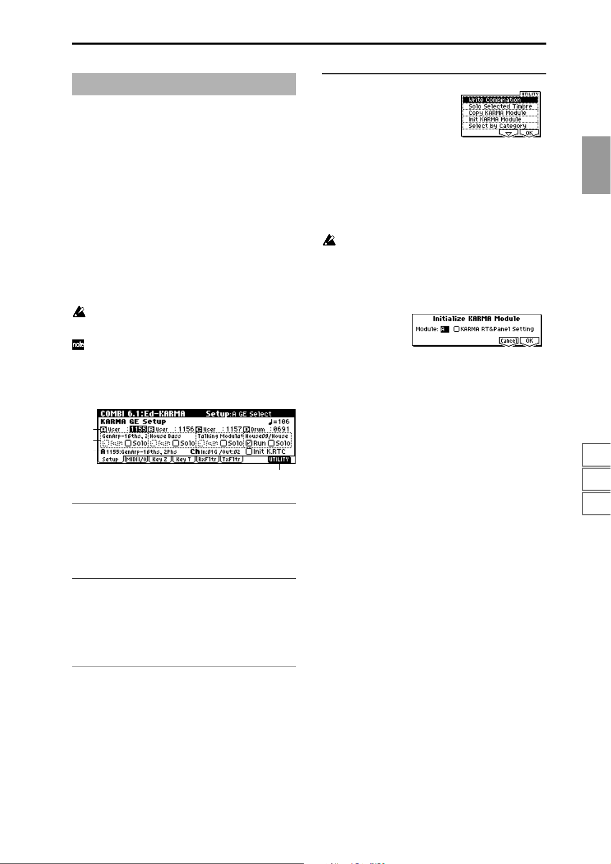
COMBI 6.1: Ed–KARMA
Here you can make KARMA function settings for the combination.
In Combination mode you can use four KARMA modules
(modules [A], [B], [C], and [D]).
A combination allows you to make a wide variety of setups,
such as assigning different phrases or patterns to programs
such as drums, bass, guitar, and strings, or combining the
four KARMA modules with eight timbre programs.
When you switch programs, these settings will automatically change to the KARMA function settings stored in that
combination. (
KARMA “Combi”: On)
KARMA function can be switched on/off by the KARMA
real-time Controls [ON/OFF] key.
The state of the KARMA real-time Controls knobs [1]–[8],
switches [1]/[2], [LATCH] and [SCENE] keys, and the note
settings/velocity of the CHORD TRIGGER [1]–[4] keys can
be saved independently for each combination.
These settings are valid if Auto KARMA “Combi” must
be On.
The parameters of 6.1–1: Setup can also be set from the
COMBI 1.1–4: KARMA page.
6.1–1: Setup
6.1–1a
6.1–1b
6.1–1c
6.1–1a: GE Category, GE Select
☞GLOBAL 1.1–1c: System Basic, Auto
6.1–1d
■ 6.1–1d: UTILITY
☞ “Write Combination,” “Solo Selected Timbre” (1.1–1c)
“Copy KARMA Module” (PROG 6.1–1d)
“Select by Category” (1.1–4d)
For the procedure, refer to “Select by Category” (
☞p.2).
Init KARMA Module (Initialize KARMA Module)
This initializes the settings of a KARMA module.
The GE selection will not be initialized. The values of the
GE parameters will be set to the default values that are
preset for the selected GE.
Nor will the “Input Channel” and “Output Channel”
(6.2–2a) settings be initialized.
1 Select “Initialize KARMA Module” to access the dialog
box.
2 Use “Module” to select the KARMA module that you
wish to initialize. If you select All, all KARMA modules
[A], [B], [C], and [D] will be initialized.
3 If you want the KARMA RT parameters and KARMA
real-time Controls settings to be initialized as well, check
“KARMA RT&Panel Setting.”
Settings initialized by “KARMA RT&Panel Setting”
• 6.4: Ed-KARMA RT settings (RT Parm, DynMIDI,
Name)
• KARMA real-time Controls knobs [1]–[8], switch [1]/
[2], [SCENE] key, [LATCH] key settings
• CHORD TRIGGER [1]–[4] key settings
4 To execute the initialization, press the [F8] (“OK”) key. To
cancel without executing, press the [F7] (“Cancel”) key.
COMBI
1.1
2.12.22.33.13.23.33.44.14.24.34.46.16.26.36.47.17.27.3
GE Category [00: name...]
GE Select [0000: Arp Model 1 Up/Dn...]
☞ p.47 1.1–4a: GE Category, GE Select
6.1–1b: GE Name, Run Check Box, Solo Check Box
GE Name
Run Check Box [Off, On]
Solo Check Box [Off, On]
☞ p.47 1.1–4b: GE Name, Run Check Box, Solo Check Box
6.1–1c: Selected GE Information, Init K.RTC
GE No., GE Name
MIDI In/Out Ch
Init K.RTC (KARMA real-time Controls– Use GE’s Value)
[Off, On]
☞ p.47 1.1–4c: Selected GE Information, Init K.RTC
57
Page 68
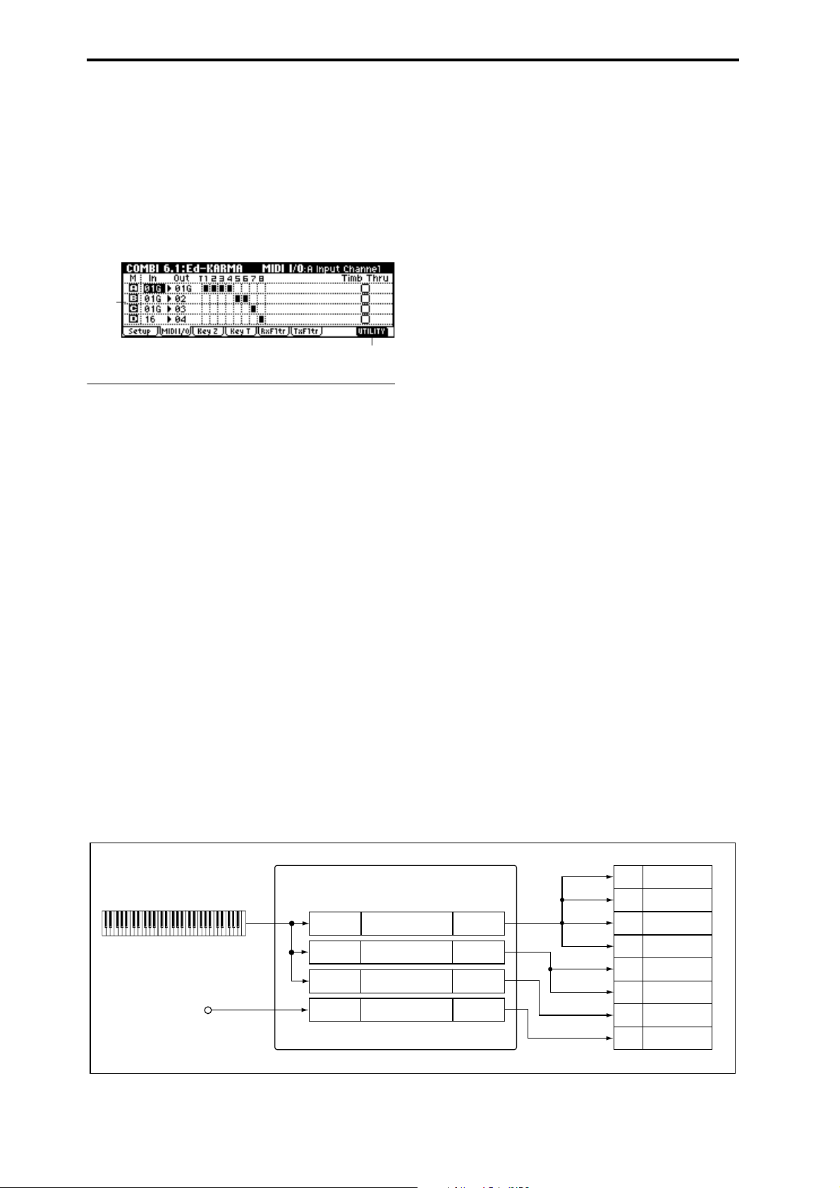
6.1–2: MIDI I/O
Specifies the MIDI input/output channels for the four
KARMA modules used by the combination.
MIDI data from the keyboard or from MIDI IN that matches
the MIDI input channel specified for a KARMA module will
be input to that KARMA module. (See the diagram below,
“KARMA-MIDI Input/Output Channel.”)
MIDI data will be transmitted from a KARMA module on
the MIDI output channel specified for that KARMA module,
and will sound timbres that match that channel.
6.1–2a
6.1–2b
6.1–2a: Input Channel, Output Channel, T.Thru
(KRM Off)
A/B/C/D Input Channel [01...16, Gch]
Specifies the MIDI input channel for each KARMA module.
MIDI data from the keyboard or from MIDI IN that matches
the specified MIDI channel will be input to the KARMA
module.
Gch: The MIDI channel will always match the global MIDI
channel “MIDI Channel” (GLOBAL 2.1–1a). When using
KARMA with keyboard playing in Combination mode, you
will normally select Gch.
A/B/C/D Output Channel [01...16, Gch]
Specifies the MIDI output channel for each KARMA module.
The MIDI data from the KARMA module will be transmitted on the specified MIDI channel, and will sound timbres
whose channel matches.
Gch: The MIDI channel will always match the global MIDI
channel “MIDI Channel” (GLOBAL 2.1–1a).
KARMA Routing Map
This shows the timbres that will be sounded by each
KARMA module, according to the MIDI output channel settings of each KARMA module and the MIDI channel of each
timbre (3.1–1a).
Timb Thru (T.Thru (KRM Off)) [Off, On]
“Input Channel” and “Output Channel” settings are normally valid only when the KARMA [ON/OFF] key is on.
As an exception, “Timb Thru” specifies whether MIDI data
that has passed through the KARMA module will be sent
(Thru) to timbres when the KARMA [ON/OFF] key is off.
On (checked): When the KARMA [ON/OFF] key is off,
MIDI data that has passed through the KARMA module will
be sent via the “Output Channel” to timbres.
Off (unchecked): When the KARMA [ON/OFF] key is off,
MIDI data that has passed through the KARMA module will
not be sent to timbres.
If you wish to apply separate phrases or patterns by using
KARMA module [A] for timbre 1 and KARMA module [B],
set the MIDI channels as follows.
[Example setting 1]
1 Set the global MIDI channel “MIDI Channel” (GLOBAL
2.1–1a) to 01.
2 Set timbre 1 as follows.
“Program Select”: Bass program
“MIDI Channel” (3.1–1a): Gch
3 Set timbre 2 as follows.
“Program Select”: Piano program
“MIDI Channel” (3.1–1a): 02
4 Set KARMA module [A] as follows.
“GE Select”: A riff of GE category Bass
“Input Channel”: Gch
“Output Channel”: Gch
“Timb Thru”: Off
5 Set KARMA module [B] as follows.
“GE Select”: A riff of GE category Keyboard
“Input Channel”: Gch
“Output Channel”: 02
“Timb Thru”: Off
6 Turn the KARMA [ON/OFF] key on.
When you play the keyboard, KARMA module [A] will
play the bass of timbre 1, and KARMA module [B] will
play the piano of timbre 2. (See “KARMA ON/OFF=ON
(1)(2)” in the diagram at the bottom of the next page.)
KARMA - MIDI Input / Output Channel
Global MIDI Ch = 01
MIDI IN
58
01ch
16ch
KARMA ON/OFF = ON
In : 01ch
In : 01ch
In : 01ch
In : 16ch
KARMA Module [A]
KARMA Module [B]
KARMA Module [C]
KARMA Module [D]
Out : 01ch
Out : 02ch
Out : 03ch
Out : 04ch
01ch
01ch
01ch
01ch
02ch
02ch
03ch
04ch
Timbre 1
Timbre 2
Timbre 3
Timbre 4
Timbre 5
Timbre 6
Timbre 7
Timbre 8
Page 69
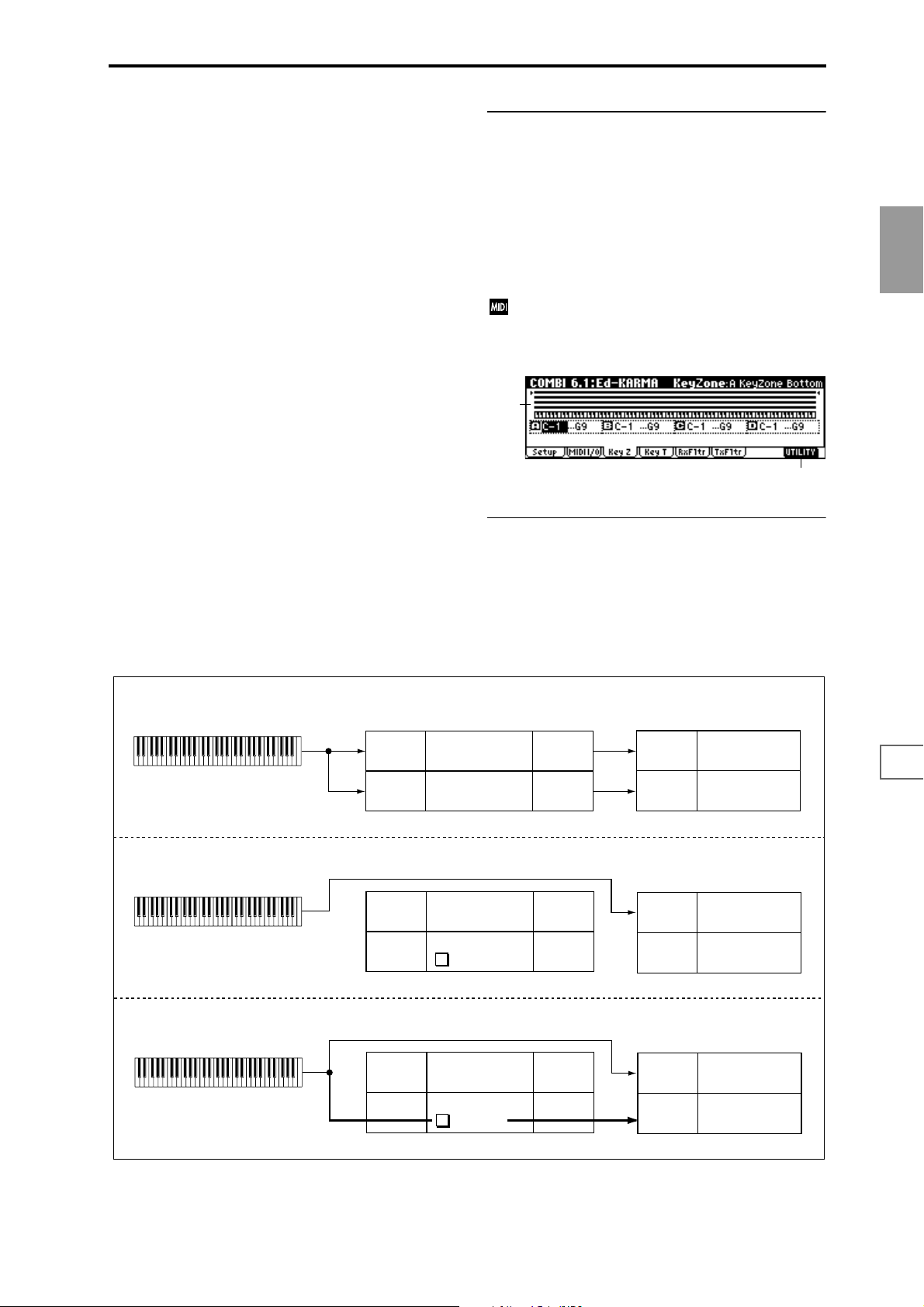
7 Turn the KARMA [ON/OFF] key off.
When you play the keyboard, you will hear the bass of
timbre 1, whose MIDI channel is set to Gch. Since timbre
2 is set to MIDI channel 2, it will not sound in response to
the keyboard. (See “KARMA ON/OFF=OFF (1)” in the
diagram below.)
[Example setting 2]
1 Make settings 1–3 of [Example setting 1].
2 Set KARMA module [A] as follows.
“GE Select”: A riff of GE category Bass
“Input Channel”: Gch
“Output Channel”: Gch
“Timb Thru”: Off
3 Set KARMA module [B] as follows.
“GE Select”: A riff of GE category Keyboard
“Input Channel”: Gch
“Output Channel”: 02
“Timb Thru”: On
4 Turn the KARMA [ON/OFF] key on.
When you play the keyboard, the result will be the same
as for
6 in [Example setting 1]. (See “KARMA ON/
OFF=ON (1)(2)” in the diagram below.)
5 Turn the KARMA [ON/OFF] key off.
When you play the keyboard, you will hear the bass timbre, whose MIDI channel is Gch. The piano of timbre 2
will also be played by the keyboard because of the
“Timb Thru” ON setting of KARMA module [B]. (See
“KARMA ON/OFF=OFF (2)” in the diagram below.)
■ 6.1–2b: UTILITY
☞ “Write Combination,” “Solo Selected Timbre” (1.1–1c)
“Copy KARMA Module” (PROG 6.1–1c)
“Init KARMA Module” (6.1–1d)
“Select by Category” (1.1–4d)
6.1–3: Key Z (KeyZone)
☞ p.27 PROG 6.1–2a: Key Z/Thru
In Combination mode, MIDI data for each KARMA
module is transmitted and received on the “Input
Channel” and “Output Channel” (6.1–2a) that you
specify for each module.
6.1–3a
6.1–3b
6.1–3a: Zone Map, KeyZone Bottom, KeyZone Top
Zone Map
The key zone settings of each of the four KARMA modules
are displayed as a solid line.
☞ p.27 PROG 6.1–2a: Key Z/Thru, “Zone Map”
COMBI
1.1
2.12.22.33.13.23.33.44.14.24.34.46.16.26.36.47.17.27.3
KARMA ON/OFF = ON (1) (2)
KARMA ON/OFF = OFF (1)
KARMA ON/OFF = OFF (2)
In : Gch
In : Gch
In : Gch
In : Gch
In : Gch
In : Gch
KARMA Module [A]
KARMA Module [B]
KARMA Module [A]
KARMA Module [B]
Timb.Thru
KARMA Module [A]
KARMA Module [B]
Timb.Thru
✓
Out : Gch
Out : 02ch
Out : Gch
Out : 02ch
Out : Gch
Out : 02ch
In : 02ch
In : Gch
In : 02ch
In : Gch
In : 02ch
Timbre 1: BassIn : Gch
Timbre 2: Piano
Timbre 1: Bass
Timbre 2: Piano
Timbre 1: Bass
Timbre 2: Piano
59
Page 70
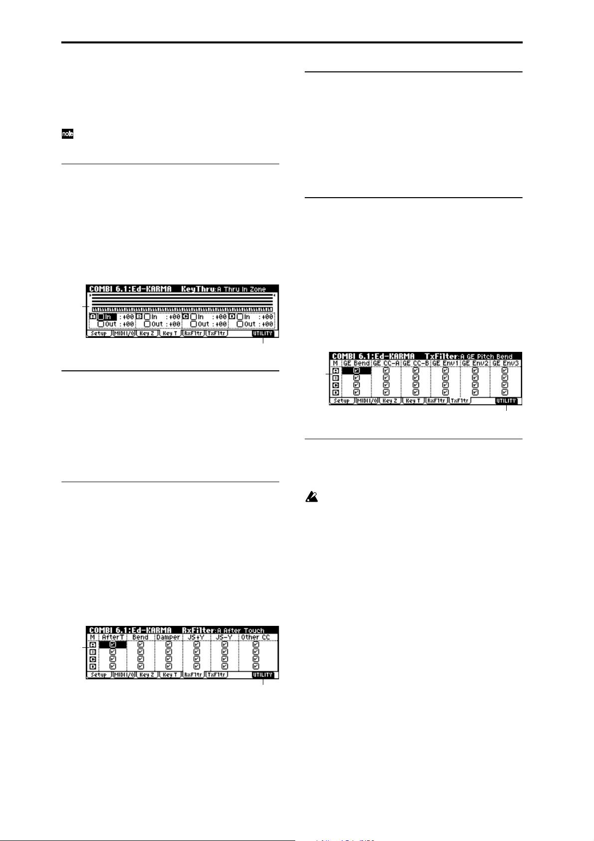
A/B/C/D KeyZone Bottom [C–1...G9]
Specifies the bottom key (lower limit) of the key zone.
A/B/C/D KeyZone Top [C–1...G9]
Specifies the top key (upper limit) of the key zone.
These parameters can also be set by holding down the
[Enter] key and playing a note.
■ 6.1–3b: UTILITY
☞ “Write Combination,” “Solo Selected Timbre” (1.1–1c)
“Copy KARMA Module” (PROG 6.1–1c)
“Init KARMA Module” (6.1–1c)
“Select by Category” (1.1–4d)
6.1–4: Key T (Key Thru)
☞ p.27 PROG 6.1–2b: Key Z/Thru
6.1–4a
6.1–4b
6.1–5a: Rx Filter
A/B/C/D AfterT (After Touch) [Off, On]
A/B/C/D Bend (Pitch Bend) [Off, On]
A/B/C/D Damper (Damper CC#64) [Off, On]
A/B/C/D JS+Y (JS+Y CC#01) [Off, On]
A/B/C/D JS-Y (JS-Y CC#02) [Off, On]
A/B/C/D Other CC [Off, On]
☞ p.28 PROG 6.1–3a: Rx Filter
■ 6.1–5b: UTILITY
☞ “Write Combination,” “Solo Selected Timbre” (1.1–1c)
“Copy KARMA Module” (PROG 6.1–1c)
“Init KARMA Module” (6.1–1d)
“Select by Category” (1.1–4d)
6.1–6: TxFltr (Transmit Filter)
For each KARMA module ([A]–[D]), specify whether to filter the MIDI control data generated by the GE selected for
the module.
☞ p.28 PROG 6.1–4a: Tx Filter
6.1–4a: Thru In Zone, Transpose InZ, Thru Out
Zone, Transpose OutZ
A/B/C/D Thru In Zone [Off, On]
A/B/C/D Transpose InZ [–36...+36]
A/B/C/D Thru Out Zone [Off, On]
A/B/C/D Transpose OutZ [–36...+36]
☞ p.27 PROG 6.1–2b: Key Z/Thru
■ 6.1–4b: UTILITY
☞ “Write Combination,” “Solo Selected Timbre” (1.1–1c)
“Copy KARMA Module” (PROG 6.1–1c)
“Init KARMA Module” (6.1–1d)
“Select by Category” (1.1–4d)
6.1–5: RxFltr (Receive Filter)
For each KARMA module ([A]–[D]), specify whether to filter the MIDI control data received by the module.
☞ p.28 PROG 6.1–3a: Rx Filter
6.1–5a
6.1–6a
6.1–6b
6.1–6a: Tx Filter
A/B/C/D GE Bend (GE Pitch Bend) [Off, On]
☞ p.28 PROG 6.1–4a: Tx Filter
If the KARMA function is on and a KARMA module is
generating pitch bend data, the Bend Range (3.1–3a) of
the timbre will be controlled as follows.
The pitch bend range specified within the KARMA GE
will be transmitted from the KARMA module so that
the corresponding timbre will be forcibly set to this
bend range. This ensures that the pitch bend data generated by the KARMA module’s GE will function as
intended. At this time, pitch bender data produced by
operating the joystick will automatically be adjusted to
produce the same bend effect as when KARMA is off
(in most cases). (If multiple timbres are being controlled
by one KARMA module, the settings of the lowestnumbered timbre will be used.)
60
6.1–5b
Page 71
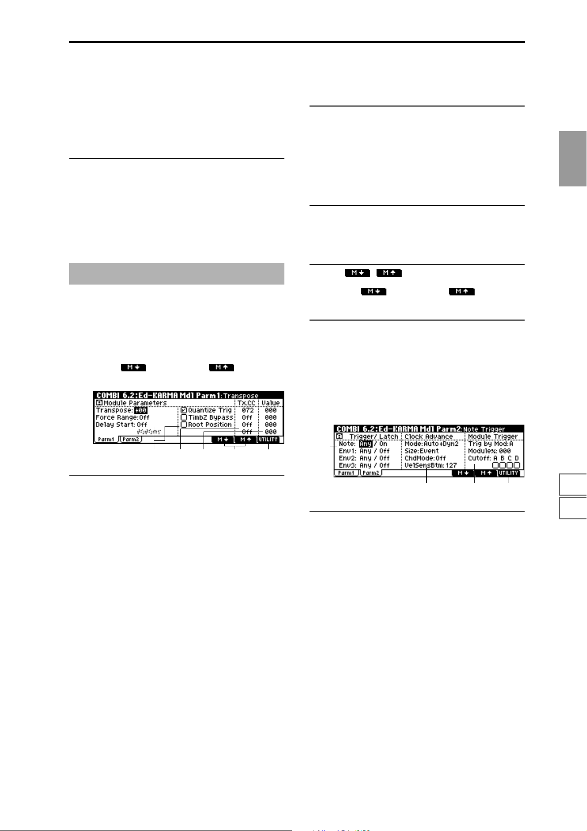
A/B/C/D GE CC-A [Off, On]
A/B/C/D GE CC-B [Off, On]
A/B/C/D GE Env.1 [Off, On]
A/B/C/D GE Env.2 [Off, On]
A/B/C/D GE Env.3 [Off, On]
☞ p.28 PROG 6.1–4a: Tx Filter
■ 6.1–6b: UTILITY
☞ “Write Combination,” “Solo Selected Timbre” (1.1–1c)
“Copy KARMA Module” (PROG 6.1–1c)
“Init KARMA Module” (6.1–1d)
“Select by Category” (1.1–4d)
Root Position [Off, On]
☞ p.29 PROG 6.2–1a: Module Parameter
6.2–1b: Tx CC (Transmit CC)
☞ p.30 PROG 6.2–1b: Tx CC
These messages will be transmitted on the “Output Channel” (6.1–2a) of the KARMA module.
Tx CC1...4 Number [Off, 000...095]
☞ p.30 PROG 6.2–1b: Tx CC
6.2–1c: Value (Tx CC Value)
COMBI
1.1
COMBI: 6.2 Ed-KARMA Mdl
6.2–1: Parm1 (Parameter 1)
Here you can set KARMA module parameters. In Combination mode, four KARMA modules ([A], [B], [C], [D]) can be
used.
Use the [F6] (“”) key and [F7] (“”) key (6.2–
1d) to select the KARMA module that you wish to edit.
6.2–1a
6.2–1c
6.2–1a: Module Parameter
The selected KARMA module is displayed as [A], [B], [C], or
[D].
Transpose [–36...+36]
Force Range
[Off, Lowest, Highest, C3–B3[1], C3–B3[2]]
Delay Start [Off, Fixed, 3...4x]
Delay Start Fixed [0000 ms...5000 ms]
Quantize Trig [Off, On]
☞ p.29 PROG 6.2–1a: Module Parameter, BG p.88 “About the
KARMA function — KARMA function synchronization”
6.2–1e6.2–1d6.2–1b
Value (Tx CC1...4 Value) [000...127]
☞ p.30 PROG 6.2–1c: Value (Tx CC Value)
6.2–1d: ,
Use the [F6] (“”) key and [F7] (“”) key to
select the KARMA module that you wish to edit.
■ 6.2–1e: UTILITY
☞ “Write Combination,” “Solo Selected Timbre” (1.1–1c)
“Copy KARMA Module” (PROG 6.1–1c)
“Init KARMA Module” (6.1–1d)
“Select by Category” (1.1–4d)
6.2–2: Parm2 (Parameter 2)
6.2–2a
6.2–2b 6.2–2c
6.2–2a: Trigger/Latch
Specifies the trigger conditions and latch on/off for the GE
that is selected for each KARMA module [A]–[D].
Note:
Note Trigger [Any, AKR, 1st, Dyn]
☞ p.31 PROG 6.2–2a: Trigger/Latch, “Note Trigger”
6.2–2d
2.12.22.33.13.23.33.44.14.24.34.46.16.26.36.47.17.27.3
TimbZ Bypass (TimbZone Bypass) [Off, On]
Specifies whether the key zone settings (3.3–1b) and velocity
zone settings (3.4–1b) of the timbre will be applied to the
phrase or pattern generated by the KARMA module.
On (checked): The key zone settings and velocity zone settings of the timbre will be bypassed for the phrase or pattern
generated by the KARMA module. The settings of the timbre will be ignored, and the notes generated by the KARMA
module will be sounded.
Off (unchecked): The key zone settings and velocity zone
settings of the timbre will be applied to the phrase or pattern
generated by the KARMA module. Notes generated by the
KARMA module will not be sounded if they are outside the
key zone or velocity zone of the timbre.
61
Page 72
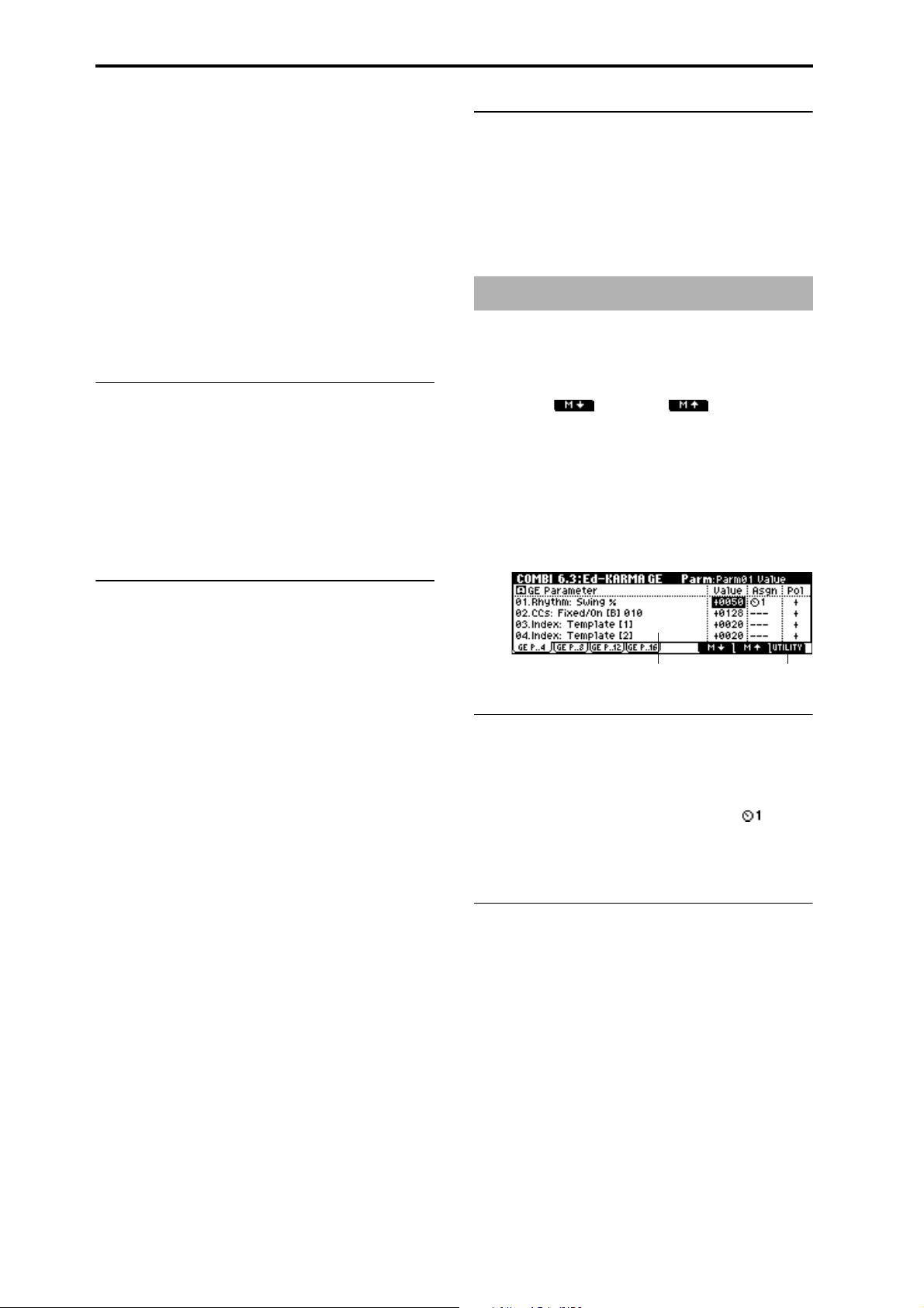
Note Latch [On, Off]
☞ p.31 PROG 6.2–2a: Trigger/Latch, “Note Latch”
In Combination mode, this can be turned on/off for each
KARMA module. A KARMA module for which this is
turned on will be in a Latch On condition when the
[LATCH] key is on (LED lit).
☞ p.31 PROG 6.2–2a: Trigger/Latch, “Note Latch”
Env1/Env2/Env3:
Env1 Trigger/Env2 Trigger/Env3 Trigger
[Any, AKR, 1st, Dyn]
Env1 Latch/Env2 Latch/Env3 Latch
[Off, Sus1, Rel1, Sus2, Rel2]
☞ p.31 PROG 6.2–2a: Trigger/Latch
6.2–2b: Clock Advance
☞ p.32 PROG 6.2–2b: Clock Advance
■ 6.2–2d: UTILITY
☞ “Write Combination,” “Solo Selected Timbre” (1.1–1c)
“Copy KARMA Module” (PROG 6.1–1c)
“Init KARMA Module” (6.1–1d)
“Select by Category” (1.1–4d)
COMBI 6.3: Ed-KARMA GE
Here you can edit the parameters of the GE selected for each
KARMA module [A]–[D]. In addition, you can assign GE
parameters to the KARMA real-time Controls so that you
can control the phrase or pattern in real-time while you play.
Use the [F6] (“”) and [F7] (“”) keys (6.2–1d) to
select the KARMA module that you wish to edit.
Mode (Clk Adv. Mode) [Auto...Auto+Dyn2]
Size (Clk Adv. Size) [3..., Event]
ChdMode (Chord Mode)
[Off, 1st, Chrd1, Chrd2, Chrd3]
VelSensBtm (Vel Sens Bottom) [001...127]
☞ p.32 PROG 6.2–2b: Clock Advance
6.2–2c: Module Trigger
Trigger by Mod (Trigger by Module) [Off, A, B, C, D]
Note and envelope triggering of a KARMA module can be
controlled by the operation of another KARMA module.
When the KARMA module you specify here advances by
the length specified in “Module%,” the KARMA module
itself will be triggered automatically, starting the phrase or
pattern.
For example you could make settings so that harp glissando
phrases specified for each KARMA module are triggered
consecutively. Alternatively, you could make settings so that
the four KARMA modules are connected in series, and play
repeatedly.
Module% [000...100]
This is valid except when “Trigger by Mod” is Off.
Cutoff (Cutoff Module) [Off, On]
This specifies whether the phrase or pattern generated by
other KARMA modules will be stopped automatically when
a KARMA module is triggered. Use this setting in cases
when KARMA modules are being triggered successively
one after the other, and you do not want the phrases to overlap.
On (checked): When a KARMA module is triggered, other
KARMA modules that are checked will stop.
6.3–1: GE P..4 (GE Parameter 1...4)
6.3–2: GE P..8 (GE Parameter 5...8)
6.3–3: GE P..12 (GE Parameter 9...12)
6.3–4: GE P..16 (GE Parameter 13...16)
6.3–1b6.3–1a
6.3–1(2), (3), (4)a: GE Parameter, Value, Asgn
(Assign), Pol (Polarity)
GE Parameter
Value
Asgn (Assign) [---, ...Dyn4]
Pol (Polarity) [–, +]
☞ p.32, 33 PROG 6.3–1a: “GE Parameter,” “Value,” “Asgn,”
“Pol”
■ 6.3–1(2), (3), (4)b: UTILITY
☞ “Write Combination,” “Solo Selected Timbre” (1.1–1c)
“Copy KARMA Module” (PROG 6.1–1c)
“Init KARMA Module” (6.1–1d)
“Select by Category” (1.1–4d)
62
Page 73
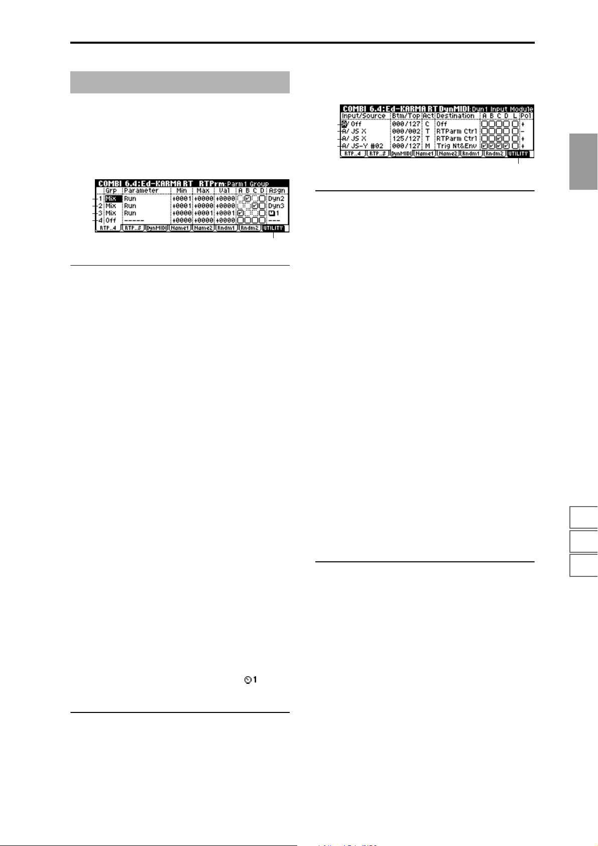
COMBI 6.4: Ed-KARMA RT
6.4–3: DynMIDI (Dynamic MIDI)
☞ p.36 PROG 6.4–3: DynMIDI (Dynamic MIDI)
6.4–1: RTP ..4 (RT Parameter 1...4)
6.4–2: RTP ..8 (RT Parameter 5...8)
☞ p.34 PROG 6.4–1: RTP ..4 (RT Parm 1...4), 6.4–2: RTP ..8
(RT Parm 5...8)
6.4–1a
6.4–1b
6.4–1c
6.4–1d
6.4–1e
6.4–1(2)a/b/c/d: RT Parm 1...4, RT Parm 5...8
Grp (Param Group) [Off, Mix, Ctrl, Trig, Zone]
☞ p.34 PROG 6.4–1(2)a/b/c/d: RT Parm 1–4, RT Parm 5...8
Parameter [---, Run...Tr.Oct/5 OutZ]
Group: Mix
Run [0, +1]
Assign the function of “Run” (1.1–4b, 6.1–1b).
0: Off
+1: Run
☞ p.47 “Run Check Box” (1.1–4b)
Group: Trig
Trig by Mod [0...+4]
Assign the function of “Trigger by Mod” (6.2–2c).
0: Off
+1: A
+2: B
+3: C
+4: D
☞ p.62 “Trigger by Mod (Trigger by Module)” (6.2–2c)
Module% [0...+100]
Assign the function of ”Module%” (6.2–2c).
☞ p.62 “Module” (6.2–2c)
6.4–3a
6.4–3b
6.4–3c
6.4–3d
6.4–3e
6.4–3a/b/c/d: Dyn MIDI1...4
Input (Dyn1...4 Input Module) [A...D]
Indicates either A, B, C, or D as the KARMA module that
will be the Dynamic MIDI “Source” input.
MIDI control data that matches the “Input CHANNEL”
(6.1–2a) of the KARMA module that you select here will be
used as the “Source.” If the “Source” is “Note In Z” or “Note
Out Z,” the zone will be the key zone (6.1–3a) of the
KARMA module that you select here.
Source (Dyn1...4 Source) [Off, JS+Y #01...Vel Out Z]
Btm (Dyn1...4 Range-Btm) [000...127]
Top (Dyn1...4 Range-Top) [000...127]
Act (Dyn1...4 Src Action) [M, T, C]
Destination (Dyn1...4 Destination)
[Off, RTParm Ctrl...Buffer Latch]
☞ p.36–PROG 6.4–3a/b/c/d: Dyn MIDI1...4
A/B/C/D (Dyn1...4 Module A/B/C/D) [Off, On]
L (Dyn1...4 Last Triggered) [Off, On]
Specifies the modules for which the Dyn MIDI1...4 settings
will be valid.
On (checked): The Dyn MIDI settings will be valid.
Off (unchecked): The Dyn MIDI settings will be ignored.
“A/B/C/D”: The settings will be valid for KARMA modules [A], [B], [C], and [D] respectively.
“L”: The settings will be valid only for the last-triggered
KARMA module [A], [B], [C], or [D].
Pol (Dyn1...4 Polarity) [Off, On]
☞ p.36–PROG 6.4–3a/b/c/d: Dyn MIDI1...4
COMBI
1.1
2.12.22.33.13.23.33.44.14.24.34.46.16.26.36.47.17.27.3
Min (Parm Min Value) [---, –0036...+5000]
Max (Parm Max Value) [---, –0036...+5000]
Value (Parm Value) [---, –0036...+5000]
A/B/C/D (Parm Module A/B/C/D) [Off, On]
Specifies whether the RT Parm settings settings will be valid
for each module.
On (checked): The RT Parm settings settings will be valid.
Off (unchecked): The RT Parm settings settings will be
ignored.
Asgn (Parm Assign) [---, ...Dyn4]
☞ p.34 PROG 6.4–1(2) a/b/c/d: RT Parm 1...4
6.41(2)e: UTILITY
☞ “Write Combination,” “Solo Selected Timbre” (1.1–1c)
“Copy KARMA Module” (PROG 6.1–1c)
“Init KARMA Module” (6.1–1d)
6.4–3e: UTILITY
☞ “Write Combination,” “Solo Selected Timbre” (1.1–1c)
“Copy KARMA Module” (PROG 6.1–1c)
“Init KARMA Module” (6.1–1d)
63
Page 74

6.4–4: Name1
6.4–5: Name2
6.4–4a
6.4–4b
6.4–4(5)a: Knob1...8, Switch1, 2
Knob 1...8 [000: no name...]
Switch 1, 2 [000: no name...]
☞ p.36 PROG 6.4–4: Name1, PROG 6.4–5: Name2
6.4–4(5)b: UTILITY
☞ “Write Combination,” “Solo Selected Timbre” (1.1–1c)
“Copy KARMA Module” (PROG 6.1–1c)
“Init KARMA Module” (6.1–1d)
6.4–6: Rndm1 (Random 1)
For example, if you select Rhythm Seed 1 for all four
KARMA modules, running the same GE under the same
conditions will cause the randomness of the rhythms to be
identical. If many types of randomness are being used, such
as duration, velocity etc., setting all the seeds to the same
value within each group will cause the resulting phrases to
be identical.
Conversely, if you select Rhythm Seed 1, 2, 3, and 4 respectively for the four KARMA modules and run the same GE
under the same conditions, the randomness of the rhythms
will be different. If many types of randomness are being
used, such as duration, velocity etc., setting all the seeds to
the different values within each group will cause the resulting phrases to be completely different.
Normally, you will select different values, such as [A]: 1, [B]:
2, [C]: 3, [D]: 4. Select identical values if you want two or
more KARMA modules to play the same GE in unison or
harmony with the same randomizations.
Changing these settings will not have any effect for GEs
that were not designed to utilize various random capabilities.
6.4–6(7)b: UTILITY
☞ “Write Combination,” “Solo Selected Timbre” (1.1–1c)
“Copy KARMA Module” (PROG 6.1–1c)
“Init KARMA Module” (6.1–1d)
“Select by Category” (1.1–4d)
6.4–7: Rndm2 (Random 2)
6.4–6a
6.4–6b
6.4–7a
6.4–7b
6.4–6(7)a: Rhythm, Duration, Index, Cluster, Velocity, CC–A/B, Drum
Rhythm (Rhythm Seed) [1, 2, 3, 4]
Duration (Duration Seed) [1, 2, 3, 4]
Index (Index Seed) [1, 2, 3, 4]
Cluster (Cluster Seed) [1, 2, 3, 4]
Velocity (Velocity Seed) [1, 2, 3, 4]
CC–A/B (CC–A/B Seed) [1, 2, 3, 4]
Drum (Drum Seed) [1, 2, 3, 4]
For the GE selected for each KARMA module, you can often
control the degree of randomness for various parameter
groups such as rhythm, duration, velocity etc. The random
calculations are performed based on initial starting values,
known as “seeds.”
64
Page 75

COMBI 7.1: Ed–BUS
Here you can specify the output bus for the program oscillator of each timbre 1–8. You can also specify the send level to
the master effects.
☞ For details on insertion effects, refer to p.159 “7. Effect
Guide.”
7.1–1: BUS (BUS T01...08)
7.1–1a
Control change #93 can be used to control the Send 1
level, and #91 to control the Send 2, and modify their
respective settings. These messages will be received on
the MIDI channel specified for each timbre in the 3.1:
Ed–Param1, MIDI page.
The actual send levels are determined by multiplying
this value with the send level “S1 (Send1(MFX)), ” “S2
(Send2(MFX))” (PROG 7.2–1a) for each oscillator of the
program selected for the timbre.
COMBI
■ 7.1–1b: UTILITY
1.1
2.12.22.33.13.23.33.44.14.24.34.46.16.26.36.47.17.27.3
7.1–1b
7.1–1a: BUS Select, Send1(MFX1), Send2(MFX2)
BUS Select [DKit, L/R, IFX1...5, 1, 2, 1/2, Off]
Specifies the output bus for the program oscillator of each
timbre 1–8. The current setting status can be viewed in the
7.2–1: Route page.
DKit: This can be selected only if the program for which settings are being made is a drum program “Mode (Oscillator
Mode) Drums” (PROG 2.1–1a). With a setting of DKit, the
“BUS Select” (GLOBAL 5.1–3a) setting made for each key of
the drum kit will be used.
For example, if the “BUS Select” settings of the drum kit
have assigned Snare sounds to IFX1 and Kick sounds to
IFX2, setting this parameter to DKit will send the Snare
sounds to IFX1 and Kick sounds to IFX2. If you wish to
modify these routings, use Utility “DKit IFX Patch” (7.1–1b).
If this is set to 1/2, the programs of timbres 1–8 will be
sent in stereo from AUDIO OUTPUT (INDIVIDUAL)
1/2. If the pan of the program oscillator is controlled by
MIDI control change #10 (pan) or AMS (Alternate Modulation Source), the sound will be output with the pan
setting that is in effect at the moment of note-on. Unlike
the case when this parameter is set to L/R to output the
sound from (MAIN) L/MONO and R, the pan of a
sounding note will not change in real-time.
If you wish to move the pan of a sounding note in realtime and output it from AUDIO OUTPUT (INDIVIDUAL) 1/2, you must set “BUS Select” to IFX1 (or IFX2–
IFX5), select 000: No Effect for “IFX1” (or IFX2–IFX5)
(7.2–1a), and for the sound that has passed through the
IFX, set “BUS Select” (7.2–1a) to either 1/2.
S1 (Send1(MFX1)) [000...127]
S2 (Send2(MFX2)) [000...127]
For each timbre 1–8, these parameters set the send level to
master effects 1 and 2. These settings are valid when “BUS
Select” is set to L/R or Off. When IFX 1, 2, 3, 4 or 5 are
selected, the send levels to master effects 1 and 2 are set by
the “S1 (Send1(MFX)), ” “S2 (Send2(MFX))” parameters of
the 7.2: Ed–InsertFX, Setup page, after the sound has passed
through IFX1–5.
If “BUS Select” is set to 1, 2 or 1/2 these settings are ignored.
☞ “Write Combination,” “Solo Selected Timbre” (1.1–1c)
For details on how to select the desired utility function, refer
to “PROG 1.1–1c: UTILITY.”
Copy Insert Effect
☞PROG 7.1–1c
However, the MIDI control channel specified for “Control
Channel” of the 7.2: Ed–InsertFX, Setup page will not be
copied.
Swap Insert Effect
☞PROG 7.1–1c
However, the MIDI control channel specified for “Control
Channel” of the 7.2: Ed–InsertFX, Setup page will not be
copied.
DKit IFX Patch (DrumKit IFX Patch)
This command applies a patch to the “BUS Select” settings
of each key of the drum kit, allowing you to temporarily
change the connections to the insert effects. This command
is available only if a drum program has been selected for the
timbre and the “BUS Select” (7.1–1a) parameter is set to
Dkit. Furthermore, this command can be executed only if
the “BUS Select” (GLOBAL 5.1–3a) for the individual keys
of that drum kit are set to IFX1–5.
1 Select “DKit IFX Patch” to access the dialog box.
2 In the right side of “DrumKit IFX 1–5→”, select the insert
effect to which you want to patch.
3 To execute the Drum Kit Insert Effect Patch command,
press the [F8] (“OK”) key. To cancel without executing,
press the [F7] (“Cancel”) key.
To restore the condition of the drum kit, execute
IFX1→IFX1, IFX2→IFX2, IFX3→IFX3, IFX4→IFX4, and
IFX5→IFX5.
65
Page 76

7.1–2: Route (Routing)
Specifies the bus to which the program used by each timbre
1–8 will be sent. Here you can also set the send levels to the
master effects.
7.1–2a
7.1–2b
7.1–2a: Routing Map, BUS Select
Routing Map
This shows the status of the insert effects. For each insert
effect, this indicates the routing, the name of the selected
effect, the on/off status, and chain status. The effect type,
on/off status and chain status can be modified in the 7.2:
Ed–InsertFX, Setup page.
T01...8: BUS Sel [DKit, L/R, IFX1...5, 1, 2, 1/2, Off]
You can specify the bus to which the program oscillator of
each timbre 1–8 will be sent, while viewing a map of the settings.
Use the cursor keys [ ], [ ] to select the timbre, and use
the VALUE [ ], [ ] key, [VALUE] slider or [VALUE] dial to
set “BUS Select” (7.1–1a).
These settings can also be made in “BUS Select” (7.1–1a).
■ 7.1–2b: UTILITY
☞ “Write Combination,” “Solo Selected Timbre” (1.1–1c),
“Copy Insert Effect,” “Swap Insert Effect,” “DKit IFX
Patch” (7.1–1b)
COMBI 7.2: Ed-InsertFX
7.2–1: Setup
Here you can select the type of each insert effect, turn it on/
off, and make chain settings etc.
7.2–1a: Ed-InsertFX Setup
IFX1 — IFX5 [Off, ON]
Insert Effect 1, 5 [000...089: name]
Insert Effect 2, 3, 4 [000...102: name]
Chain [ (Off), (On)]
Pan(CC#8) [L000...C064...R127]
BUS Select [L/R, 1, 2, 1/2, Off]
S1 (Send1 (MFX1)) [000...127]
S2 (Send2 (MFX2)) [000...127]
These parameters are the same as in Program mode.
(
☞PROG 7.2–1)
However, dynamic modulation (Dmod) of the insert effects
and the “Pan (CC#8), “Send 1 (MFX1),” and “Send 2
(MFX2)” that follow the insert effects will be controlled on
the “Control Channel” (7.2-1b) MIDI channel, unlike in Program mode. The control changes used are the same as in
Program mode.
7.2–1b: Control Channel
Control Channel [Ch01...16, G ch, All Rt.]
Specifies the MIDI channel on which dynamic modulation (Dmod) of the insert effects and the “Pan (CC#8),
“Send 1 (MFX1),” and “Send 2 (MFX2)” that follow the
insert effects will be controlled.
The channel number of the timbre routed through this IFX
will be followed by a “*” displayed at the right of Ch01–16.
If two or timbres with different MIDI channel settings are
routed through the same IFX, this parameter specifies which
of these channels will be used to control the effect.
G ch: The global MIDI channel “MIDI Channel” (GLOBAL
2.1–1a) will be used to control the effect. Normally you will
set this to G ch.
All Rt. (All Routed): The channel of any timbre routed
through this effect can be used to control the effect. (Channels of each routed timbre will be indicated by “*”.)
If the “BUS Select” (7.1–1a) of a timbre for which a
drum program is selected is set to DKit, the MIDI channel of that timbre will be valid if any IFX1–5 is set to All
Rt., regardless of the “BUS Select” (GLOBAL 5.1–3a)
settings or the settings of the Utility “DrumKit IFX
Patch” (7.1–1b).
66
7.2–1a
■ 7.2–1c: UTILITY
☞ “Write Combination,” “Solo Selected Timbre” (1.1–1c),
“Copy Insert Effect,” “Swap Insert Effect” (7.1–1b), “Select
7.2–1c7.2–1b
by Category” (PROG 7.2–1b)
Page 77

7.2–2: IFX 1 (Insert Effect1)
7.2–3: IFX 2 (Insert Effect2)
7.2–4: IFX 3 (Insert Effect3)
7.2–5: IFX 4 (Insert Effect4)
7.2–6: IFX 5 (Insert Effect5)
These are the parameters for IFX 1, 2, 3, 4, and 5 that were
selected in the Setup page (
☞p.168).
COMBI 7.3: Ed–MasterFX
☞ For details on insertion effects, refer to p.159 “7. Effect
Guide.”
7.3–1: Setup
Here you can select the type of each master effect, turn it
on/off, and make chain and master EQ settings.
With the exception of “MFX1 Control Ch,” “MFX2 Control
Ch,” and “MEQ Control Ch,” this is the same as in Program
mode. (
☞PROG 7.3: Ed-MasterFX)
COMBI
1.1
7.2–2a
■ 7.2–2(...6)a: UTILITY
☞ “Write Combination” (1.1–1c)
7.2–7: Route (Routing)
7.2–7a
7.2–7b
7.2–7a: Routing Map
This shows the status of the insert effects. This shows the
same content as the 7.1: BUS, Routing page. (
■ 7.2–7b: UTILITY
☞ “Write Combination,” “Solo Selected Timbre” (1.1–1c),
“Copy Insert Effect,” “Swap Insert Effect,” “DKit IFX
Patch” (7.1–1b)
☞7.1–2a)
7.3–1a
7.3–1b
7.3–1e7.3–1c7.3–1d
7.3–1a: MasterFX Setup
MFX1 On/Off, MFX2 On/Off [Off, ON]
Master Effect 1, 2 [000...089: name]
Rtn 1, 2 (Return 1, 2) [000...127]
These are the same as in Program mode. Refer to “PROG
7.3-1: Setup.” However, the master effects will be controlled
on the “MFX 1, 2 Control Ch” MIDI channel, unlike in Program mode.
The control changes used are the same as in Program mode.
MFX 1, 2 Control Ch [Ch01...16, G ch]
Selects the MIDI channel that will control dynamic
modulation (Dmod) for the master effects.
G ch: The global MIDI channel “MIDI Channel” (GLOBAL
2.1-1a) will be used for control. Normally you will set this
parameter to G ch.
7.3–1b: MasterFX Chain
MFX Chain [Off, On]
Direction (Chain Direction)
[MFX1→MFX2, MFX2→MFX1]
Signal (Chain Signal) [LR Mix, L Only, R Only]
Level (Chain Level) [000...127]
These are the same as in Program mode. (☞“PROG 7.3–1:
Setup”)
2.12.22.33.13.23.33.44.14.24.34.46.16.26.36.47.17.27.3
7.3–1c: Master EQ Gain [dB]
Low [–18.0...+18.0]
Mid [–18.0...+18.0]
High [–18.0...+18.0]
These are the same as in Program mode. (☞PROG 7.3–1:
Setup)
67
Page 78

7.3–1d: MEQ Ctrl
MEQ Ctrl (MEQ Control Ch) [Ch01...16, G ch]
Selects the MIDI channel that will control dynamic
modulation (Dmod) for the master EQ.
G ch: The global MIDI channel “MIDI Channel” (GLOBAL
2.1–1a) will be used for control. Normally you will set this
parameter to G ch.
7.3–4: MEQ (Master EQ)
The master EQ is a three-band stereo EQ. It is located immediately before the AUDIO OUTPUT (MAIN OUT) L/
MONO and R from the L/R bus, and adjusts the overall
tonal character of the sound (
☞p.220).
■ 7.3–1e: UTILITY
☞ “Write Combination,” “Solo Selected Timbre” (1.1–1c),
“Select by Category” (PROG 7.3–1d)
For details on how to select the desired utility function, refer
to “PROG 1.1–1c: UTILITY.”
Copy Master Effect
☞p.41 PROG 7.3–1d
Note, the MIDI control channel that is specified by “MFX1, 2
Control Ch” (7.3–1a) will not be copied.
Swap Master Effect
☞p.41 PROG 7.3–1d
Note, the MIDI control channel that is specified by “MFX1, 2
Control Ch” (7.3–1a) will not be swapped.
7.3–2: MFX1 (Master Effect1)
7.3–3: MFX2 (Master Effect2)
Here you can set the parameters of the “Master Effect1” and
“Master Effect2” effects that were selected in the Setup page
☞p.168).
(
7.3–4a
■ 7.3–4a: UTILITY
☞ “Write Combination” (1.1–1c)
■ 7.3–2(3)a: UTILITY
☞ “Write Combination” (1.1–1c)
68
7.3–2a
Page 79

3. Sequencer mode
In Sequencer mode you can use the built-in 16-track
sequencer to play, record and edit songs. You can also record
and play patterns, make settings for the RPPR (Real-time
Pattern Play Recording) function, play songs that use the
KARMA function, record patterns, and create Cue Lists to
playback multiple songs consecutively.
These settings and the song data you recorded are not
backed up when the power is turned off. Before turning
off the power, be sure to save important data on a
floppy disk or a data filer. Immediately after the power
is turned on, memory will not contain any song data, so
in order to playback the sequencer, you will need to
load data from the floppy disk, or receive a MIDI bulk
data dump from an external MIDI sequencer (
☞p.140).
SEQ PAGE MENU
For details on how to select pages in Sequencer mode, refer
to p.1.
BUS 7.1: BUS Set BUS and master effect send level for
each track.(
IFX 7.2: Insert FX Insert effect routing, selection, and set-
tings. (
MFX 7.3: Master FX Master effect selection and settings. Mas-
ter EQ settings. (
☞p.111)
☞p.112)
☞p.113)
SEQ 1.1: Play/REC
Here you can select songs, and make basic settings such as
selecting the program used by each track.
1.1–1: Play.REC (Play/REC)
Here you can select songs and turn RPPR on/off.
1.1–1a
1.1–1b
1.1–1c
1.1–1d
SEQ
1.11.22.12.22.33.13.23.33.44.14.24.34.45.15.26.16.26.36.4
P/R 1.1: Play/REC Select multis. Select a program for each
Loop 1.2: Loop Make settings for track play loop function.
Cue 2.1: Cue List Play, create, and make settings for cue
Ctrl 2.2: Controller Controller settings. (
MOSS 2.3: MOSS Displayed if the separately sold EXB-
Prm1 3.1: Param1 MIDI, OSC, and pitch settings for each
Prm2 3.2: Param2 Turn track playing b y KARMA on/off, delay
KeyZ 3.3: Key Zone Key zone settings for each track. (
VelZ 3.4: Vel Zone Velocity zone settings for each track.
MIDI1 4.1: MIDI Filter1 MIDI message transmission/reception fil-
MIDI2 4.2: MIDI Filter2 Filter settings: JS, Ribbon Ctrl etc.
MIDI3 4.3: MIDI Filter3 Filter settings: real-time Control Knob
MIDI4 4.4: MIDI Filter4 Filter settings: SW, Other Ctrl Change
RPPR 5.1: RPPR Pattern recording and editing. RPPR set-
TEdit 5.2: Track Edit Edit track playback data. Specify track
KARM 6.1: KARMA KARMA GE selection and settings, MIDI
K Mdl 6.2: KARMA Mdl Module parameters (transpose, range of
K GE 6.3: KARMA GE GE parameter settings and assignments
K RT 6.4: KARMA RT KARMA RT parameters, Dynamic MIDI
track, and make pan and level settings.
☞p.69)
(
☞p.77)
(
☞p.78)
lists. (
☞p.81)
MOSS option is installed. Make EXBMOSS parameter settings. (
☞p.82)
track. (
and scale settings for each track. (
☞p.86)
(
ter settings for each track: Prog Change,
After Touch etc. (
☞p.88)
(
☞p.89)
(
☞p.89)
(
tings. (
☞p.90)
names. (
channel, key zone parameters, and MIDI
filter settings. (
generated phrase, trigger etc.). (
to KARMA real-time Controls (
settings. (
☞p.87)
☞p.95)
☞p.103)
☞p.110)
☞p.82)
☞p.84)
☞p.85)
☞p.108)
☞p.109)
1.1–1a: Location, Meter Reso (Resolution),
(Tempo), Tempo Mode
Location [001:01.000...999:16.191]
This is the current location of the song. From the left, the
numbers are the measure, beat, and clock. When you modify
these values, the current location will change.
When “MIDI Clock” (GLOBAL 2.1–1a) is Internal,
changing the location will cause Song Position Pointer
messages to be transmitted. If this parameter is set to
External, Song Position Pointer messages from the
specified source will change the location.
The range in which the beat and clock can be modified
will depend on the currently specified time signature.
7.17.27.3
69
Page 80
Meter [*/*, 1/4...16/16]
This is the time signature at the current location of the song.
The time signature can be changed at each measure.
*/*: This will be displayed when you press the [REC/
WRITE] key. Specify this when you wish to use the time signature that is already recorded for that measure, and wish to
record without changing the time signature.
1/4–16/4, 1/8–16/8, 1/16–16/16: This is the time signature at
the current location of the song. After pressing the front
panel [REC/WRITE] key, specify the time signature here.
Then press the [START/STOP] key to begin recording, and
the specified time signature will be recorded on the Master
Track and on previously-recorded tracks. Be aware that if
you press the [START/STOP] key during the pre-count to
stop recording, the time signature will not be recorded.
Normally, you will specify the time signature when you
record the first track, and select */* when recording subsequent tracks.
Recording from measure 2 of track 2
when Meter = */*
Track 1
Track 2
Track 1
Track 2
1 (4/4) 2 (3/4)
1 (4/4)
1 (4/4) 2 (3/4)
1 (4/4) 2 (3/4)
3 (4/4)
Recording
3 (4/4)
3 (4/4)
Track 1
Track 2
Track 1
Track 2
when Meter =7/8
1 (4/4) 2 (3/4)
1 (4/4)
1 (4/4) 2 (7/8)
1 (4/4) 2 (7/8)
3 (4/4)
Recording
3 (7/8)
3 (7/8)
3 (4/4)
4 (7/8)
4 (7/8)
Changing the time signature in the middle of a measure
If you know beforehand the location at which you wish to
change time signatures in the middle of a measure, use
“Insert Measure” (5.2–1b) to specify and insert the time signature for each measure of the same time signature, and
then record your musical data. Alternatively, if you wish to
change the time signature in the middle of a song which
already contains musical data, use “Track Select” (1.1–1c) to
specify the Master Track (or any Track01–16 which contains
data), and use “Event Edit” (5.2–1c) to modify the time signature of the Bar event.
If the number of beats in a measure increases when you
modify the time signature, rests will be inserted in the portion that was added. Conversely if the number of beats
decreases, that portion will not be played. However if you
return to the original time signature, the data that had been
hidden will once again be played.
Rest is inserted
Not played
Reso (Real-time Quantize Resolution) [Hi, 3...]
This corrects the timing of data as it is recorded in real-time.
(It does not affect previously-recorded data.)
Hi (High Resolution): Timing will not be corrected. Data
will be recorded at the maximum resolution (/192).
3 – : Data will be corrected to the nearest interval of the
specified timing as it is recorded. For example if you select
3 , data will be corrected to the nearest 32nd note triplet
interval. If you select , data will be corrected to the nearest
quarter note interval.
With a setting of
Since all that musical data that is recorded will be corrected
to the specified timing resolution, coarse settings of this
parameter will cause continuous controllers such as pitch
bend to be recorded in “stairstep” fashion.
In such cases, use a setting of Hi to record, and then use
“Quantize” (5.2–1b) to correct only the desired type of data
(notes etc.). It is best to avoid recording at a stiff resolution
to begin with.
(Tempo) [040…240, EXT]
This sets the playback tempo of the song and the tempo of
the KARMA function.
040...240: When the “Tempo Mode” is Manu, this tempo will
be used for recording and playback. When “Tempo Mode”
is REC, this tempo will be recorded on the master track.
EXT: This will appear when “MIDI Clock” (GLOBAL 2.1–1a)
is External. The tempo of the internal sequencer will synchronize with the MIDI Clock messages received from an
external sequencer etc. When “MIDI Clock” is Internal, the
above tempo setting (040...240) will be used.
If Te m po is selected as an alternate modulation source,
= 120 will be the base value.
Tempo Mode [Auto, Manu, REC]
Auto: The tempo will follow the tempo of the Master Track.
The tempo of the master track can be specified by using
“Event Edit” (5.2–1b) with Master Track chosen in “Track
Select,” (1.1–1c) or by the REC operation described below.
When Auto is selected, it will not be possible to modify the
“ (Tempo)” setting while a song is playing or recording (or
during standby).
Manu (Manual): The “ (Tempo)” setting will be used.
REC: Tempo changes will be recorded on the Master Track.
Select this after pressing the [REC/WRITE] key. When REC
is selected and you are recording in real-time, modify the
“Te mp o” value to change the tempo. This cannot be selected
when the Preferences page item “Recording Setup” is set to
Loop All Tracks. Tempo changes can also be created using
“Event Edit” (5.2–1b) or “Create Control Data” (5.2–1b).
If you wish to record only the tempo changes, set “REC
Setup” (1.1–6a) to OverDub, and the tempo will be
recorded on the master track without being affected by
the musical data of “Track Select.”
1.1–1b: Song Select
Song Select [000...199: name]
Indicates the song that you wish to record or play.
If you wish to create a new song, you can either select a
number from the popup menu for which the song name is
blank, or use the numeric keys [0]–[9] to directly specify the
song number, then press the [ENTER] key to access the dialog box, and finally press the [F8] (“OK”) key.
70
Page 81

If “MIDI Clock” (GLOBAL 2.1–1a) is Internal, changing
the song will cause Song Select and Song Position
Pointer messages to be transmitted. If “MIDI Clock” is
External, Song Select messages can be received from
the specified source to change songs. When the song
changes, tracks whose track status (“Status” (3.1–1a)) is
EXT, EX2 or BTH will transmit Bank Select, Program
Change, Volume, Panpot, Poramento, Send1, 2, Post
IFX Pan, and Post IFX send 1, 2 messages on the MIDI
channel of the respective track.
1.1–1c: RPPR (Real-time Pattern Play/Rec), Track
Select, Selected Track Information
RPPR [Off, On]
This turns the RPPR (Real-time Pattern Play/Recording)
function on/off. RPPR lets you assign a pattern to each note
of the keyboard, so that the pattern will playback (or be
recorded) when you press the appropriate key.
On (checked): The RPPR function will be on. If a pattern has
been assigned to each key in the 5.1–2: RPPR Setup page,
pressing that key will perform the assigned pattern (
RPPR Setup).
☞5.1–2:
Track Select [T01...T16: name, Master Track]
Track01–Track16: Select the track(s) that will record or play
song data.
The track names specified in “Rename Track” (5.1–1c).
When you perform real-time recording on a single track, the
musical data will be recorded on the track you select here.
When you perform real-time recording on two or more
tracks simultaneously (
MUTE/REC” (1.1–2(3)b) will select the recording track,
regardless of the setting you make here.
Master Track: Select the master track when you wish to use
the 5.2–1: Track Edit page menu commands to edit the
tempo track. When using real-time recording or step recording, it is not possible to record the master track alone.
When you play the keyboard of this instrument and
operate its controllers, the internal tone generator will
sound according to the settings (program, level etc.) of
the tracks that are selected here (if “Status” 3.1–1a is
INT or BTH), and other tracks whose MIDI channels
match will also sound at the same time (if “Status” is
INT or BTH). Messages will also be transmitted on the
MIDI channels of these tracks (whose “Status” is EXT,
EX2 or BTH).
☞“Multi REC” 1.1–6a), the “PLAY/
Selected Track Information
This shows information on the “Track Select” that is currently selected for editing.
T (Track) No.: Bank No.: Prog No. and name
This displays the track number, and the bank, number, and
name of the program selected for that track.
■ 1.1–1d: UTILITY
For details on how to select the desired utility function, refer
to “PROG 1.1–1c: UTILITY.”
Memory Status
This displays the remaining amount of sequencer memory.
Solo Selected Track
The Solo function will alternate on/off each time you select
this command.
When checked, the Solo function will be turned on, and
only the currently selected track will sound. Other tracks
will be muted. To solo another track, select a parameter of
the desired track. “Selected Track Information” (1.1–1c) will
indicate [Solo].
To defeat the Solo function, select the “Solo Selected Track”
page menu command once again.
Even if multiple “SOLO On/Off” (1.1–2(3)b) settings
are On, turning on the Solo function here and selecting
“SOLO On/Off” or the parameter of another track will
cause only that track to be soloed and sounded.
If the tracks that have been muted by the Solo function
have a “Status” (3.1–1a) setting of EXT, EX2, or BTH,
the MIDI note-on/off messages of that track will not be
transmitted.
Rename Song
Here you can rename the selected song. A name of up to sixteen characters can be input. (
☞BG p.39)
Delete Song
This command deletes the currently selected song.
1 Select this command to access the dialog box.
2 If you wish to execute the Delete Song command, press
the [F8] (“OK”) key. To cancel, press the [F7] (“Cancel”)
key. When you execute this command, the musical data,
setting data, and patterns etc. of the currently selected
song will be erased, and the memory area allocated to
that song will be freed.
Copy From Song
Copy all settings and musical data from the song you specify to the currently selected song.
1 Select “Copy From Song” to access the dialog box.
SEQ
1.11.22.12.22.33.13.23.33.44.14.24.34.45.15.26.16.26.36.4
Ch 01...16
This shows the MIDI channel number specified for the track.
7.17.27.3
71
Page 82
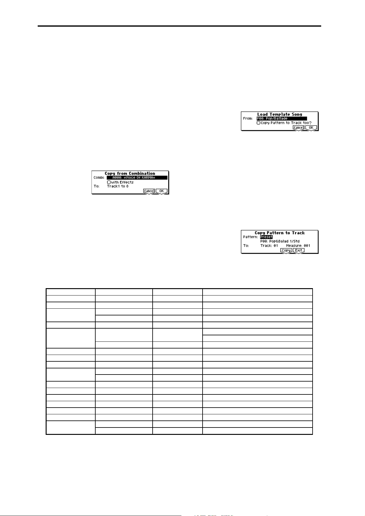
2 In “From,” select the copy source song number.
3 Select the data that will be copied.
All: Copy all musical data (e.g., track events and patterns) and settings.
Without Track/Pattern Events: Only song settings other
than Play Loop and RPPR will be copied.
4 To execute Copy Song, press [F8] (“OK”) key. To cancel
without executing, press [F7] (“Cancel”) key.
If you execute All, all musical data and settings of the
currently selected song will be erased, and replaced by
the copy source data.
If you execute Without Track/Pattern Events, song set-
tings other than Play Loop and RPPR will be erased, and
replaced by the copy source data.
Copy From Combi (Copy From Combination)
Copy the settings of the combination you specify to the settings of the currently selected song.
1 Select “Copy From Combi” to access the dialog box.
2 In “Combi,” select the copy source combination.
3 Check or uncheck “with Effects” to specify whether effect
and EQ settings will also be copied.
If this is checked, the insert effect, master effect, and master EQ settings will also be copied.
4 In “To , ” select the copy destination tracks (1–8 or 9–16).
5 To execute the copy, press [F8] (“OK”) key. To cancel
without executing, press [F7] (“Cancel”) key.
When you execute, the settings of the currently selected
song will be erased, and replaced by the settings of the
combination.
Load Template Song
This command loads a template song as a song.
The built-in sequencer contains sixteen different preset tem-
plate songs (P00–15) that contain preset settings for pro-
grams and effects appropriate for various musical styles.
You are also free to create your own favorite settings for programs, track parameters, and effects, and save them as one
of sixteen user template songs (U00–15) (
Template Song”).
1 Select “Load Template Song” to access the dialog box.
2 In “From,” specify the template song that you wish to
load.
3 If you check “Copy Pattern to Track too?,” the “Copy
Pattern To Track” dialog box will appear automatically
after “Load Template Song” has been executed.
If you execute without checking this, only the template
song you specified in step
2 will be loaded.
4 To load the template song, press the [F8] (“OK”) key. To
cancel without loading, press the [F7] (“Cancel”) key.
When you execute, song settings other than Play Loop
and RPPR will be copied.
If in step
3 you checked “Copy Pattern to Track too?”
and pressed the [F8] (“OK”) key, the “Copy Pattern To
Track” dialog box will appear.
This dialog box is the same as in 5.1: Pattern/RPPR, Pattern Edit tab, utility menu command “Copy To Track”
☞p.93).
(
☞“Save as User
Preset Template Song Track No.: Name Program Corresponding Preset Pattern No.:Name
P00: Pop/Ballade Track01: Drums A036:Standard Kit P00: Pop&Balad 1/Std ... P10: Pop(6/8) 3/Std
P01: Rock/Metal Rock Track01: Drums B020:Processed Kit P11: Rock 1/Process ... P21: Rock11/Process
P02: R & B Track01: Drums 1(Std 2) B036:Standard Kit 2 P22: R&B 1/Std2 ... P27: R&B 6/Std2
Track09: Drums 2(Std) A036:Standard Kit P28: R&B 7/Std ... P32: R&B11/Std
P03: Jazz Track01: Drums B004:Jazz/Brush Kits P33: Jazz 1/Jazz ... P39: Jazz 7/Jazz
P04: Latin Track01: Drums B004:Jazz/Brush Kits P40: Latin 1/Jazz ... P42: Latin 3/Jazz
P46: Latin 7/Jazz ... P47: Latin 8/Jazz
Track08: Percussion B116:Percussion Kit P43: Latin 4/Perc ... P45: Latin 6/Perc
P05: Reggae Track01: Drums B068:Drum'nBass Kit P48: Reggae 1/D'n'B ... P53: Reggae 6/D'n'B
P06: Country Track01: Drums A036:Standard Kit P54: Country 1/Std ... P57: Country 4/Std
P07: Folk Track01: Drums A036:Standard Kit P58: Folk 1/Std ... P61: Folk 4/Std
P08: European Trad. Track01: Drums A036:Standard Kit P62: E.Trad 1/Std ... P67: E.Trad(3/4)2/Std
Track08: Percussion B116:Percussion Kit —
P09: Orchestral Track01: Percussion A116:Orchestra&Ethnic —
P10: Techno/Euro Beat Track01: Drums A020:House Kit P68: Techno 1/House ... P78: Techno11/House
P11: House Track01: Drums A020:House Kit P79: House 1/House ... P92: House14/House
P12: Drum'n'Bass Track01: Drums B068:Drum'n'Bass Kit P93: Drum'nBs 1/D'n'B ... P108: Drum'nBs16/D'n'B
P13: Acid Jazz Track01: Drums B036:Standard Kit 2 P109: AcidJazz 1/Std2 ... P120: AcidJazz12/Std2
P14: Hip Hop/Rap Track01: Drums A068:HipHop Kit P121: HipHop 1/HipHop ... P135: HipHop15/HipHop
P15: Big Beats Track01: Drums 1(Hip/Hop) A068:HipHop Kit P136: Bigbeat 1/HipHop ... P143: Bigbeat 8/HipHop
Track09: Drums 2(Tricky) A004:! {Tricky} Kit! P144: Bigbeat 9/Tricky ... P149: Bigbeat14/Tricky
72
Page 83
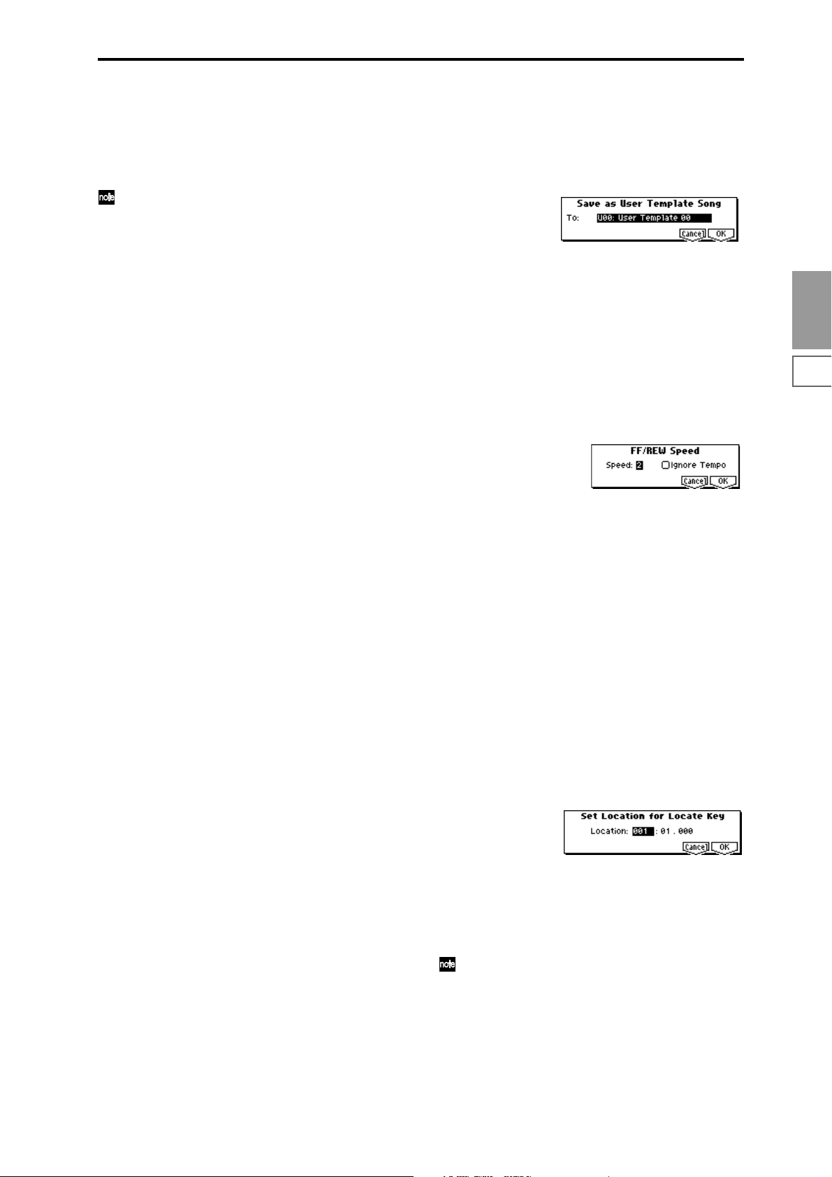
5 In “Pattern,” select the pattern that you wish to copy. If
you press the [START/STOP] key, the selected pattern
will play.
In To “Track,” select the copy destination track.
In “Measure,” specify the beginning measure of the copy
destination.
Track 1 of all sixteen preset template songs contains a
drum category program. (In preset template songs P02,
P04, P08, and P15 drum category programs are specified for multiple tracks.)
The pattern names of the 150 preset patterns indicate
the musical genre and part of the optimal drum category program. (
For example in P00: Pop&Balad 1/Std, the musical
genre is “Pop&Balad 1,” and “Std” is part of the name
of the drum category program that is most suitable.
By loading the drum track for these preset template
songs and the corresponding preset patterns, you can
efficiently set up a drum track that is suited to each preset template song.
6 To execute, press the [F6] (“Copy”) key. When you exe-
cute, “Measure” will count up automatically. You may
then copy patterns as well. To exit the command, press
the [F7] (“Exit”) key.
Example)
Load preset template song P00: Pop/Ballade together
with preset pattern P01: Pop&Balad 2/Std into song
S000
1 Select “Load Template Song” to access this dialog box.
2 In “From,” select P00: Pop/Ballade.
3 Check “Copy Pattern to Track too?”
4 Press the [F8] (“OK”) key to access the “Copy Pattern To
Track” dialog box.
5 Set “Pattern” to Preset to select preset patterns, and
select one of the patterns P00: Pop&Balad 1/Std–
P07: Pop&Balad 8/Std for the pattern name. (Preset tem-
plate song P00: Pop/Ballade specifies program A036:
Standard Kit for track 1.) If you wish to play the selected
pattern, press the [START/STOP] key. If you wish to
adjust the tempo, use the [TEMPO] knob.
For this example, select P01: Pop&Balad 2/Std.
6 Set To:”Track” to 01, and “Measure” to 001.
7 Press the [F6] (“Copy”) key once. The eight-measure pre-
set pattern P01: Pop&Balad 2/Std has now been copied
to the song. “Measure” will count-up automatically.
By repeating steps
other patterns. When you press the [F7] (“Exit”) key, the
dialog box will close.
☞Lower diagram)
5 and 7 you can continue to copy
Save Template Song (Save as User Template Song)
This command saves the program selections, track parameters, and effect settings etc. of the song as a user template
song U00–15. The settings you save here can also be loaded
in Song Play mode.
1 Select “Save Template Song” to access the dialog box.
2 In “To ,” specify the user template song (U00–15) in which
the data will be saved.
3 To save the template song, press the [F8] (“OK”) key. To
cancel, press the [F7] (“Cancel”) key. Be aware that when
you execute this command, all setting data of the save
destination User Template Song will be erased and
rewritten.
FF/REW Speed
This allows you to set the speed at which fast-forward or
rewind will occur when you press the [FF] key or [REW]
key.
1 Select “FF/REW Speed” to access the dialog box.
2 In “Speed,” specify the speed (relative to the playback
tempo) at which fast-forward and rewind will occur.
With a setting of 2, this will occur at double the playback
tempo; with a setting of 3, triple the tempo; and with a
setting of 4, quadruple the tempo. However in sections
where the playback data is dense, the fast-forward or
rewind speed may slow down.
3 If “Ignore Tempo” is checked, the playback tempo and
note length will be ignored, and fast-forward and rewind
will be performed as fast as possible. The speed of fastforward and rewind will differ between sections where
the playback data is dense and sections where it is sparse.
If this item is unchecked, fast-forward and rewind will
be performed at the speed you specify for “Speed.”
4 To execute the settings, press the [F8] (“OK”) key. To can-
cel, press the [F7] (“Cancel”) key.
Set Location (Set Location for Locate Key)
When you press the [LOCATE] key, you will move to the
location specified here.
1 Select “Set Location” to access the dialog box.
SEQ
1.11.22.12.22.33.13.23.33.44.14.24.34.45.15.26.16.26.36.4
2 In “Location,” specify the location to which you will
move when you press the [LOCATE] key. If you specify
001:01:000, you will move to the beginning of the song
when you press the [LOCATE] key.
3 To execute the settings, press the [F8] (“OK”) key. To can-
cel, press the [F7] (“Cancel”) key.
Even when this dialog box is not opened, you can set
this value to the current location by holding down the
[ENTER] key and pressing the [LOCATE] key.
7.17.27.3
73
Page 84
1.1–2: Prog...8 (Program T01...08)
1.1–3: Prog...16 (Program T09...16)
Here you can make basic settings for playback and recording of songs and select the program that will be used by
each track.
1.1–2a
1.1–2b
1.1–1c
1.1–2c
1.1–2(3)a: Program
Program Select
[A...F/000...127, G001...128 g001:1...g128:d]
Here you can select the program that will be used by each
track.
F000...F127 can be selected if a separately sold EXB-MOSS
option is installed.
When this parameter is selected, you can use the VALUE
controller to make a selection. At this time, the BANK
SELECT key LEDs will light to indicate the bank of the
selected program.
The track number and the abbreviated category name of the
selected program are displayed above “Program Select.”
By holding down the [TIMBRE/TRACK] key and
pressing a [F1](T1/T9)–[F8](T8/T16) key you can move
to the corresponding track “T1”–”T16.”
The program bank can also be selected directly by using
the BANK [A]–[G] keys.
When this parameter is selected, you can use the Utility
menu command “Select by Category” to select a program by category. (
The program you select here will be used when the song is
played or recorded from the beginning. If the program is
changed while recording, the program change will be
recorded as musical data, and the program will change during playback. You can also change the program manually
during playback. However if musical data (program change
data) is already recorded, the program will change at that
point.
If the “Status” (3.1–1(2)a) is INT or BTH, the program
can be specified by receiving a MIDI program change.
When you switch songs or return to the beginning of
the song, tracks whose “Status” is EXT, EX2, or BTH
will transmit the bank and program number via MIDI.
Tracks whose “Status” is EX2 will display the Bank as
“–,” and will transmit via MIDI the bank number speci-
fied by “Bank (EX2) MSB” and “Bank (EX2) LSB” in the
Param1 page (3.1–1(2)a).
☞p.2)
1.1–2(3)b: PLAY/MUTE/REC, SOLO On/Off
PLAY/MUTE/REC [PLAY, MUTE, REC]
Specifies the mute status of each track, and select the recording tracks for multi-track recording. During playback or single track recording (normal recording), you can select PLAY
or MUTE for tracks other than the recording track. During
multi-track recording, each track can be set to PLAY, MUTE,
or REC. Use the VALUE [ ][ ] keys, the [VALUE] slider,
or the [VALUE] dial to change the setting.
PLAY: The track will play.
MUTE: The track will be muted (silent).
REC: This will appear in single track recording (normal
recording). It cannot be selected.
If you have selected multi-track recording (Preference page
“Multi REC” on), select REC for the tracks that you wish to
record.
SOLO On/Off [SOLO On, SOLO Off]
Turn the Solo function on/off.
Select the box located at the right of “PLAY/MUTE/REC,”
and turn the setting on/off. A track for which this is turned
on will show an “S” in the box, and only that track will
sound. The other tracks will be muted.
In the case of tracks whose “Status” (3.1–1(2)a) is BTH,
EXT, or EX2, a track that has been muted by the Mute or
Solo functions will not transmit note on/off data on the
MIDI channel specified for that track.
If the utility menu command “Solo Selected Track”
(1.1–1d) is on, its solo state will take priority. When you
press “SOLO On/Off” or a parameter of another track,
only that track will be soloed, and will be heard.
■ 1.1–2(3)c: UTILITY
☞ “Memory Status,” “Solo Selected Track,” “Rename Song,”
“Delete Song,” “Copy From Song,” “Copy From Combi,”
“Load Template Song,” “Save Template Song,” “FF/REW
Speed,” “Set Location” (1.1–1d)
Select by Category
Select the program for each track by category.
This will appear and can be selected when “Program Select”
is selected. (☞PROG 1.1–1a)
74
Page 85
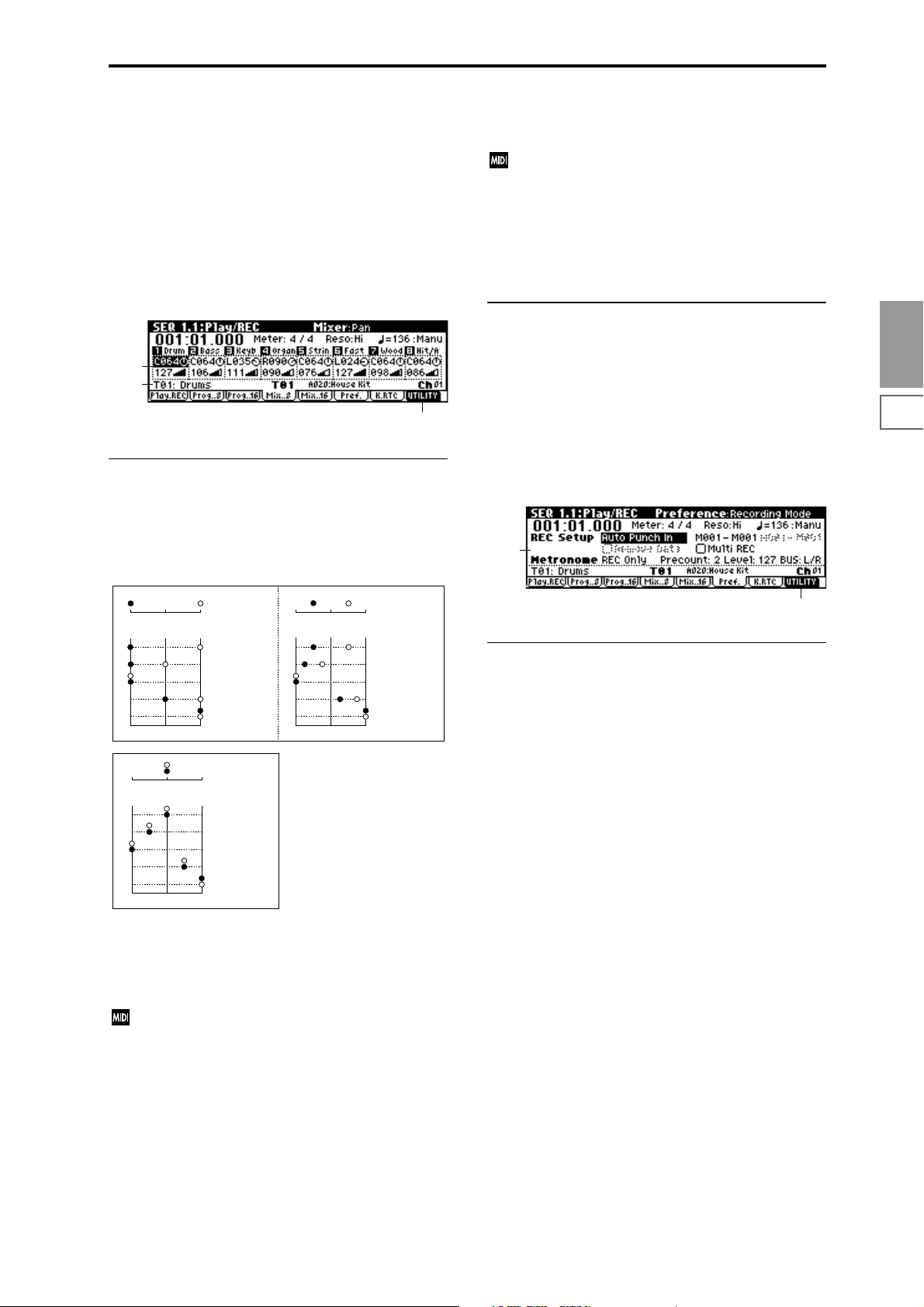
1.1–4: Mix..8 (Mixer T01...08)
1.1–5: Mix..16 (Mixer T09...16)
Here you can set the pan and volume of each track.
The pan and volume that you specify here will be used
when you playback or record from the beginning of the
song. If you change the settings during recording, the
changes will be recorded as musical data, and pan and volume will change during playback. You can also change the
settings during playback. However when the song reaches a
location where pan or volume data was recorded, the settings will change accordingly.
Volume [000...127]
Set the volume of tracks 1–16.
When “Status” (3.1–1(2)a) is INT or BTH, CC#7 Volume
can be received to control the volume. The volume of a
track is determined by multiplying the MIDI Volume
(CC#7) and Expression (CC#11) values. When you
change the song or return to the beginning of the song,
tracks whose “Status” is EXT, EX2 or BTH will transmit
the volume you specify here as a MIDI Volume message.
■ 1.1–4(5)b: UTILITY
1.1–4a
1.1–1c
1.1–4b
1.1–4(5)a: Pan, Volume
Pan (Panpot) [RND, L001...C064...R127]
Sets the pan of tracks 1–16.
L001...C064...R127: A setting of L001 is far left, and R127 is
far right. A setting of C064 will reproduce the pan setting of
the oscillator in Program mode.
OSC1
Left
Left
OSC1
Left
Left
If a mono-type insertion effect is inserted, this setting will be
ignored. In this case, the 7.2: Insert Effect Setup page “Pan
(CC#8)” setting will adjust the pan of the sound following
the insertion effect.
RND: The sound will be panned randomly at each note-on.
If “Status” (3.1–1(2)a) is INT or BTH, CC#10 Panpot
can be received to control the panning. When receiving
CC#10, a value of 0 or 1 is far left, 64 is center, and 127 is
far right. When you change the song or return to the
beginning of the song, tracks whose “Status” is EXT,
EX2 or BTH will transmit the pan you specify here as a
MIDI message (except for RND).
Center
Center
Center
Center
OSC2
OSC1: Amp1 Pan=L001
OSC2: Amp2 Pan=R127
Right
Pan (CC#10)
C064
L032
L001
R096
R127
Right
OSC2
OSC1: Amp1 Pan=C064
OSC2: Amp2 Pan=C064
Right
Pan (CC#10)
C064
L032
L001
R096
R127
Right
OSC1: Amp1 Pan=L032
Left
Center
Left
Center
OSC2: Amp2 Pan=R096
Right
Pan (CC#10)
C064
L032
L001
R096
R127
Right
☞ “Memory Status”, “Solo Selected Track”, “Rename Song”,
“Delete Song”, “Copy From Song”, “Copy From Combi”,
“Load Template Song”, “Save Template Song”, “FF/REW
Speed”, “Set Location” (1.1–1d)
1.1–6: Pref. (Preference)
Here you can select the method of real-time recording, and
set the metronome.
1.1–6a
1.1–6b
1.1–6a: Rec Setup, Metronome
Indicates the method of real-time recording.
Refer to BG p.62 for the real-time recording.
REC Setup:
Recording Mode [Over Write...Loop All Tracks]
Over Write
When recording for the first time, you will normally select
this method.
To begin recording, press the [REC/WRITE] key and then
the [START/STOP] key. To stop recording, press the
[START/STOP] key once again.
Be aware that when this method of recording is used to
record on a track that already contains data, any previously
existing data will be erased from the measure at which you
begin recording and from all subsequent measures.
Over Dub
Select this when you wish to add data to a previouslyrecorded track.
To begin recording, press the [REC/WRITE] key and then
the [START/STOP] key. To stop recording, press the
[START/STOP] key once again.
Previously-recorded data will remain in the track, and the
newly-recorded data will be added.
SEQ
1.11.22.12.22.33.13.23.33.44.14.24.34.45.15.26.16.26.36.4
7.17.27.3
75
Page 86

Manual Punch In
Select this method when you wish to use the [REC/WRITE]
key or a foot switch to re-record selected portions of a previously-recorded track.
Press the [START/STOP] key to playback the song. When
you reach the measure at which you wish to begin re-writing the data, press the [REC/WRITE] key or the foot switch,
and recording will begin. When you are finished recording,
press the [REC/WRITE] key or the foot switch once again,
and recording will end.
The area between the points where you pressed the [REC/
WRITE] key or the foot switch the first and second times
will be replaced by the newly recorded data.
Auto Punch In
Select this method when you wish to automatically rerecord selected portions of a previously-recorded track.
If you select Auto Punch In, the display will indicate “M***–
M*** (Auto P Start Meas–Auto P End Meas)” at the right,
allowing you to specify the range of measures that will be
rewritten.
Press the [REC/WRITE] key and then the [START/STOP]
key, and playback will occur until the specified measure is
reached. Then, recording will occur only over the specified
area (“Auto P Start Meas”–“Auto P End Meas”), rewriting it
with the newly recorded data.
Loop All Tracks
Select this method when you wish to repeatedly record a
specified area of a track, and continue adding data. This is
suitable for creating drum patterns, etc.
If you select Loop All Tracks, the display will indicate “
M***–M*** (Loop Start Meas–Loop End Meas)” at the right,
allowing you to specify the range of measures that will be
recorded repeatedly.
Press the [REC/WRITE] key and then the [START/STOP]
key, and playback will occur until the specified measure is
reached. Then, recording will occur repeatedly over the
specified area (“Loop Start Meas”–“Loop End Meas”). Previously-recorded data will remain, and the new data will be
added. While recording, you can check “Remove Data” to
delete unwanted data.
If you check “Multi REC,” Loop All Tracks cannot be
selected.
Auto P Start Meas–Auto P End Meas
[M001...M999–M001...M999]
When “Recording Mode” is set to Auto Punch In, specify
the measures at which recording will start and end.
Loop Start Meas–Loop End Meas
[M001...M999–M001...M999]
When “Recording Mode” is set to Loop All Tracks, specify
the measures over which recording will continue repeating.
Remove Data [Off, On]
You can delete unwanted musical data while recording with
Loop All Tracks.
This is available when Loop All Tracks is chosen in
“Recording Mode.”
On (checked): During recording, press the key (note number) that corresponds to the musical data you wish to delete.
All occurrences of that note number will be deleted for the
interval that you continue holding down the key. Controller
data can also be erased in a similar way. For example while
you move and hold the joystick in the X (horizontal) direction, bender data will be erased. While you apply pressure
to the keyboard, after touch data will be erased.
Also, you can press and hold down the [REC/WRITE] key
to delete all musical data for as long as the key is held.
Multi REC [Off, On]
On (checked): Multi-track recording mode will be selected.
Check this when you wish to record multiple tracks simultaneously.
If this is checked, the “PLAY/MUTE/REC” (1.1–2(3)b) setting of all tracks will be set to REC.
At this time, use the Program page (1.1–2(3)a) “PLAY/
MUTE/REC” setting to specify the tracks on which multitrack recording will occur. (
The Multi REC setting also allows MIDI data on multiple
channels to be received from a multi-track sequencer connected to this instrument, and recorded simultaneously on
multiple tracks.
In this case, MIDI data of matching MIDI channels will be
recorded on tracks whose “PLAY/MUTE/REC” (1.1–2(3)b) is
set to REC, regardless of the “Track Select” (1.1–1c) setting.
When you do this, it is a good idea to set “MIDI Clock”
(GLOBAL 2.1–1a) to External so that this instrument will
synchronize to the external sequencer. However, tempo
changes will not be recorded.
Off (unchecked): Single track recording mode will be
selected. Recording will occur on the track you select in
“Track Select.”
☞BG p.64)
Metronome:
Here you can make metronome settings.
Sound [REC Only, REC/Play, Off]
REC Only: The metronome will sound only during recording.
REC/Play: The metronome will sound during recording and
playback.
Off: The metronome will not sound. However, the pre-count
will sound before recording begins.
This parameter is linked to SEQ 5.1: RPPR Pattern “Metronome Sound” (5.1–1b).
Precount [0…2]
Specifies the pre-count that will occur before recording
begins.
With a setting of 0, recording will begin the instant you press
the [START/STOP] key (after first pressing the [REC/
WRITE] key).
Level [000…127]
Sets the volume of the metronome.
BUS (BUS Select) [L/R, L, R, 1, 2, 1/2]
Select the output destination of the metronome sound.
L/R, L, R: Output from OUTPUT (MAIN) L/Mono and/or R.
1, 2, 1/2: Output from OUTPUT (INDIVIDUAL) 1, 2, respec-
tively.
■ 1.1–6b: UTILITY
☞ “Memory Status”, “Solo Selected Track”, “Rename Song”,
“Delete Song”, “Copy From Song”, “Copy From Combi”,
“Load Template Song”, “Save Template Song”, “FF/REW
Speed”, “Set Location” (1.1–1d)
76
Page 87
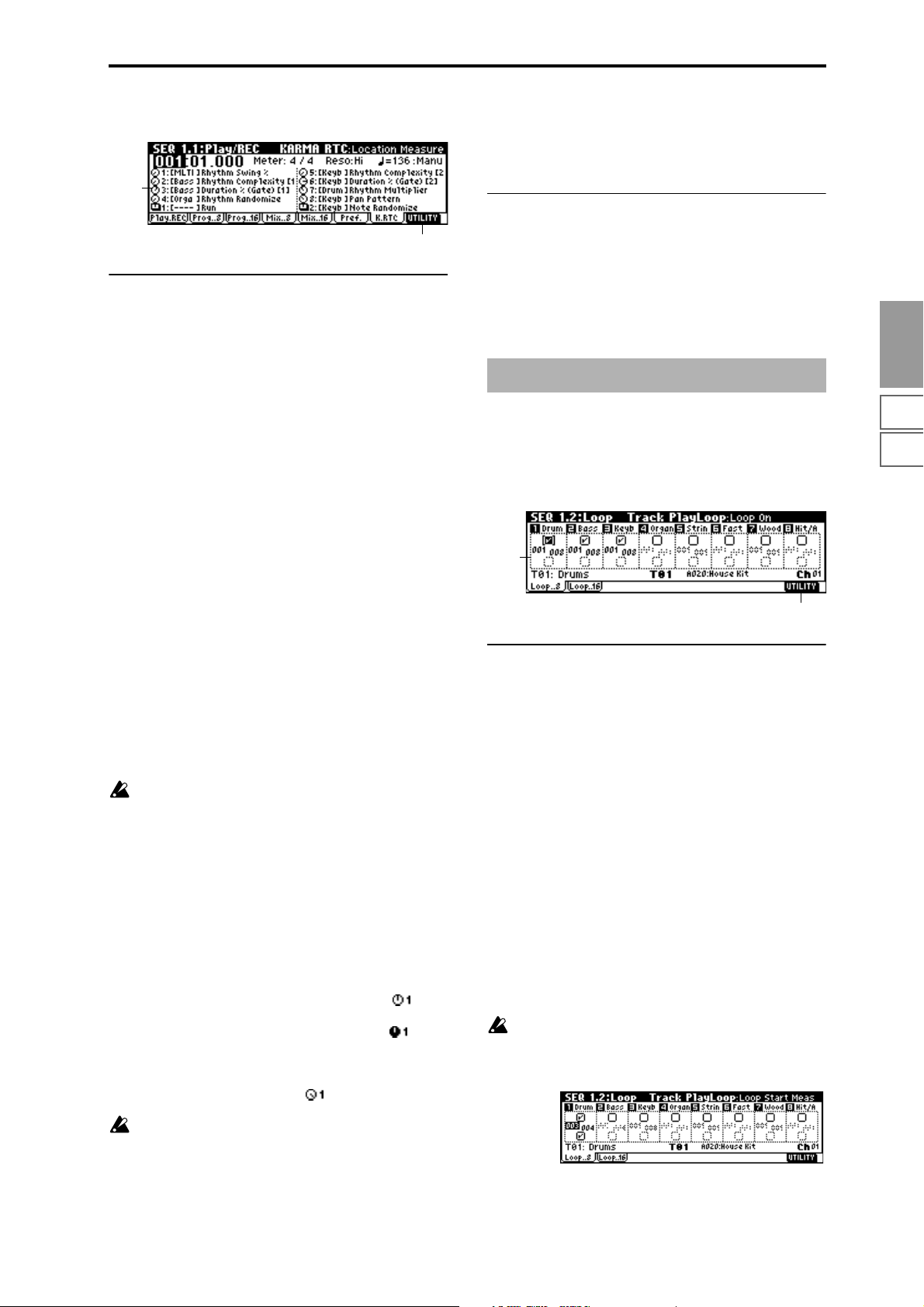
1.1–7: K.RTC (KARMA RTC)
1.1–7a
gram mode “Restoring only SCENE settings,” “Restoring only the knob and switch settings.”)
It is a good idea to save your favorite knob and switch
settings on a floppy disk or data filer.
■ 1.1–7b: UTILITY
1.1–7b
1.1–7a: RT Knob/SW Name
This screen displays the names of the KARMA Real-time
Controls knobs and switches, and the knob and switch settings of the song.
The [---] area displayed before each knob or switch name
shows the abbreviated category name for the program
selected by the track that will be played by the KARMA
module controlled by operating the knob or switch. If there
are multiple programs of different categories, this will indicate [MLTI].
Parameter assignments are specified in the SEQ 6.3:
KARMA GE: Parm page (6.3–1(2)(3)(4)) and SEQUENCE
6.4: KARMA RT RTPrm page (6.4–1(2)).
The name can be edited in the SEQ 6.4–4/5: KARMA RT,
Name 1/2 page.
The settings of the KARMA Real-time Controls knobs and
switches can be switched between two different settings by
using the SCENE [1]/[2] keys. The knob and switch settings
displayed here will also change according to the SCENE 1/2
setting.
Graphic display of knobs and switches
When you operate a knob or switch to modify the setting it
originally had when the song was selected, the graphic display of the knob or switch will be highlighted in black.
When you return the knob or switch to the setting it originally had when the song was selected, the display will
return to the previous state.
This provides a convenient way for you to return to the original state after you have operated a knob or switch.
A Sequencer mode song has a different structure than a
program or combination, and a different reference
value is used to highlight the knob or switch graphic. In
the case of a program or combination, the knob or
switch value that is written will be the reference value.
However in Sequencer mode, the settings at the
moment that the song was selected will be the reference
value. (The settings when the song was selected will be
the settings at the time of loading or last editing.) The
operation is as described below.
1 Select song 000.
The position of knob 1 when song 000 was selected
will be the center (64).
At this time, the knob 1 graphic will show .
2 Turn knob 1 all the way to the right (127).
The knob 1 graphic will be highlighted as .
3 Select a different song (e.g., song 001).
4 Select song 000 once again.
The knob 1 setting will be the far right setting (127).
The knob 1 graphic will be .
In Sequencer mode, it is not possible to use the
“Restore entire program” operation that is available in
Program and Combination modes. You can use the
“Restore only SCENE settings” and “Restore only
knob and switch settings” operations to revert to the
settings at the time the song was selected. (
☞p.6 Pro-
☞ “Memory Status”, “Solo Selected Track”, “Rename Song”,
“Delete Song”, “Copy From Song”, “Copy From Combi”,
“Load Template Song”, “Save Template Song”, “FF/REW
Speed”, “Set Location” (1.1–1d)
SEQ 1.2: Loop
1.2–1: Loop...8 (Track Play Loop T01...08)
1.2–2: Loop...16 (Track Play Loop T09...16)
When playing/recording a song, you can independently
loop the playback of tracks 1–16.
1.2–1a
1.2–1b
1.2–1(2)a: Track Play Loop
Loop On [Off, On]
Turn looping on/off for each track 1–16.
On (checked): That track will loop between “Loop Start
Meas” and “Loop End Meas.”
Loop Start Meas (Loop Start Measure) [001...999]
Specifies the first measure of the loop.
Loop End Meas (Loop End Measure) [001...999]
Specifies the last measure of the loop.
Play Intro [Off, On]
On (checked): After the measures before the specified “Loop
Start Meas” are played once, the region of “Loop Start
Meas” – “Loop End Meas” will be played repeatedly.
For example, you can use this on a drum track to make it
play a fill-in and then begin looping.
Off (unchecked): Playback will begin from the “Loop Start
Meas,” and will begin looping immediately. (This is how
Version 1 operated.)
This will be valid if “Track Play Loop” is checked and
“Loop Start Meas” is set to other than 001.
Example)
When “Play Intro” is checked
SEQ
1.11.22.12.22.33.13.23.33.44.14.24.34.45.15.26.16.26.36.4
7.17.27.3
77
Page 88
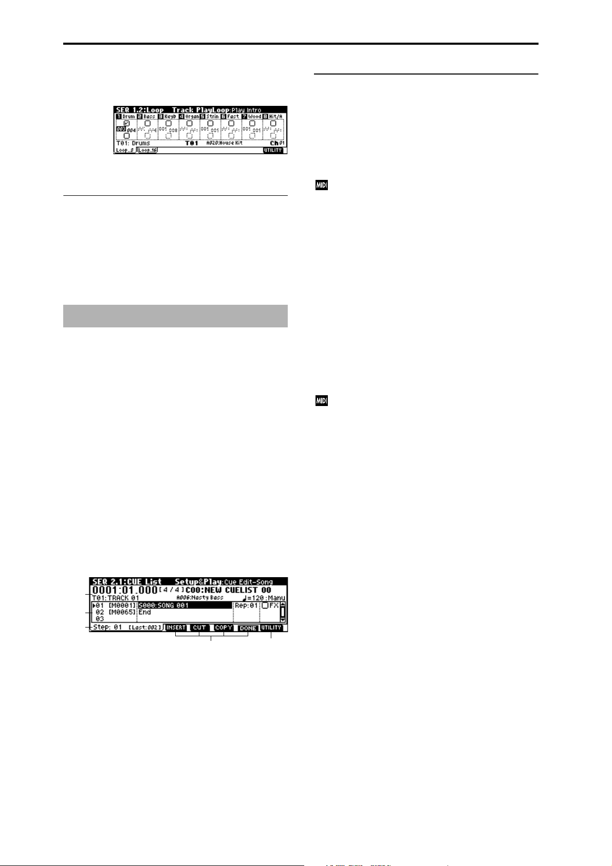
Track 1 will loop as follows.
M001–M002–M003–M004–M003–M004–M003–M004…
When “Play Intro” is not checked
Track 1 will loop as follows.
M003-M004-M003-M004-M003-M004-M003-M004...
1.2–1(2)b: UTILITY
☞ “Memory Status”, “Solo Selected Track”, “Rename Song”,
“Delete Song”, “Copy From Song”, “Copy From Combi”,
“Load Template Song”, “Save Template Song”, “FF/REW
Speed”, “Set Location” (1.1–1d)
SEQ 2.1: Cue List
2.1–1: Cue List
The cue list allows you to playback multiple songs in succession. You can specify a number of repetitions for each song.
This instrument allows you to create twenty cue lists. In a
single cue list you can freely connect up to 99 songs.
Each unit in a cue list is called a “step,” and you can specify
a song number and a repeat (number of repetitions) for each
step.
For example you could create each part of a song (intro, melody A, melody B, break, solo backing, ending etc.) as an
individual song, and use a cue list to play the intro twice,
melody A four times, melody B four times, the break twice,
melody A four times ... etc. to produce the entire song. In
cases when you wish to change the structure of the song,
this Cue List function can help you work more efficiently.
The utility menu command “Convert to Song” (2.1–1e) lets
you convert the songs in a cue list into a single song. For
example you can use a cue list to create the backing, convert
the cue list to a song, and then add solo phrases on unused
tracks.
2.1–1a:Location, Meter, Cue List Select, Track Select,
Selected Track Information, , Tempo Mode
Location [0001:01.000…9999:15.191]
This displays the current location within the selected cue
list. From the left, the numbers indicate the measure, beat,
and clock.
The range of the beat and clock will depend on the time signature of the corresponding song.
When “MIDI Clock” (Global 2.1–1a) is Internal, changing the location within a cue list will cause Song Position Pointer messages to be transmitted. If “MIDI
Clock” is External, this message can be received from
the specified source to change the location within the
cue list.
If the location exceeds the allowable data range of a
Song Position Pointer message, it will not be transmitted.
Meter (Time Signature) [1/4...16/16]
This displays the time signature of the currently-playing
song.
Cue List Select [C00...C19: name]
Indicates the cue list that you wish to play.
When using a cue list to play songs, you must first load the
necessary data into internal memory, either from floppy
disk, or by a MIDI data dump from an external sequencer
(
☞p.140).
When “MIDI Clock” (GLOBAL 2.1–1a) is Internal,
selecting a cue list in this page will cause a Song Select
message (corresponding to the cue list number) and
Song Position Pointer message to be transmitted. When
“MIDI Clock” is External, a Song Select message from
the specified source will switch cue lists.
Track Select [T01...T16: name]
Indicates the track that you wish to play manually from the
keyboard along with the playback. While a cue list is playing, you can play along using the track settings and musical
data of the song selected by the current “Step” (2.1–1c). The
track you select here will also follow the track settings and
musical data of the currently playing song. If you wish to
continue using the same program to play along from the
keyboard with consecutive songs, specify the same program
for this track in the songs of each Step.
78
2.1–1a
2.1–1b
2.1–1c
Selected Track Information
This area shows the program bank number, program number, and name of the track selected in “Track Select.”
(Tempo) [040...240, EXT]
2.1–1e2.1–1d
Specifies the tempo at which the song in the cue list will be
played (
☞“1.1–1a: Tempo”).
Tempo Mode [Auto, Manu]
Auto: Playback will use the tempo specified by the currently
playing song. During playback, the “ (Tempo)” setting can-
not be modified.
Manu (Manual): Tempo specified in the song will be
ignored, and playback will use the tempo specified above
for “ (Tempo).”
Page 89

2.1–1b: Step, Cue Edit-Song, Rep (Cue Edit-Repeat),
FX (Cue Edit-Load FX)
Here you can create and edit a Cue List. Immediately after
the power is turned on, the cue list will show a default cue
list of two “Steps,” consisting of “Step” 01 (S000: NEW
SONG) and “Step” 02 (End).
To create or edit a cue list, press the [F7] (“EDIT”) key. If you
now select a song for “Step” 01, that song will play once. If
you set “Rep (Repeat)” to 02, that song will play twice.
Press [F7] (“EDIT”), and with “Step” 01 selected, press the
[F4] (“Insert”) key to insert a step.
For example with “Song” S001 selected for “Step” 01, set
“Rep” to 02, select “Song” S002 for “Step” 02 and set “Rep”
to 02. When you press the [START/STOP] key, song 1 (S001)
will be played twice, and then song 2 will be played twice.
In this way, arrange the desired songs in the cue list and
specify the number of times that each will be played.
Step [Measure] [01...100 (M0001...M9999)]
This shows the step number and its beginning measure.
When playback is stopped, the step currently selected by
“Step” (2.1–1c) will be a black triangle. When you use the
[START/STOP] key to begin playback, it will begin from this
step. While a cue list is playing, the playing step will be a
black triangle.
“M**** (Measure)” shows the beginning measure of each
step. It cannot be edited.
Cue Edit-Song
[S000...S199: name, End, Continue to Step01]
This selects the song for the step. It cannot be selected during playback.
You can also select whether playback will end with the last
step in the cue list, or whether playback will return to “Step”
01 and continue endlessly.
End: Playback will end.
Continue to Step01: Playback will return to “Step” 01, and
the cue list will continue playing endlessly. To stop, press the
[START/STOP] key.
Rep (Cue Edit-Repeat) [01...64, FS]
Specifies the number of times that the song of this step will
be repeated.
FS: A foot switch connected to the rear panel can be used to
specify the point at which the song will stop repeating.
When you press the foot switch, that repetition of the song
will finish playing, and then playback will continue to the
next step. Set “Foot Switch Assign” (GLOBAL 6.1–1a) to Cue
Repeat Control.
FX (Cue Edit-Load FX) [Off, On]
Specifies whether the effect settings will also change simultaneously when the playback advances to the song of the
next step.
On (checked): The effect settings will change to those of the
newly selected song.
Off (unchecked): The effect settings will not change.
Depending on the effect settings, a certain amount of
time may be required to switch effects. In this case,
playback will not be smoothly connected from song to
song.
If you want to transition smoothly from song to song,
check “FX” in “Step” 01. For the remaining steps, do
not check “FX” With these settings, the effects will be
set before playback begins, so there will be no time lag
to interrupt the smooth transition between songs.
Although it is not possible to change the effect types in
the middle of a cue list, you can use the dynamic modulation function or MIDI control changes (effect control)
to apply reverb more deeply to certain songs, or raise
the LFO speed for other songs, etc. When using a cue
list to construct a song, we recommend this method.
When you execute the “Convert to Song” (2.1–1e) page
menu command, the effect settings of the “Step” 01
song will be specified at the beginning of the song that
is created by the conversion.
Even when “FX” is not checked, there may be a time
lag in the transition from one song to the next, depending on the musical data in the song. There may also be
cases in which the musical data at the transition
between songs does not play at the correct timing. To
fix this, you can edit the musical data of the song, or
convert the cue list to a single song. If you use “Convert
to Song” (2.1–1e) to convert the cue list to a song, there
will be no time lag at the transition, and the musical
data will play at the correct timing.
2.1–1c: Step (Current Step)
Step (Current Step) [01...100]
Indicates the step that will be inserted, cut or copied.
If you wish to playback from a step in the middle of the cue
list, select the desired step here, and press the [START/
STOP] key.
Last Step [Last: 001...100]
This will be displayed at the right of “Step” for the last step.
2.1–1d: EDIT/DONE, INSERT, CUT, COPY
EDIT/DONE ([F7])
Press this to create or edit a cue list. When you press this key,
the display will change from “EDIT” to “DONE.”
When you are finished creating or editing the cue list, press
“DONE” (the [F7] key).
INSERT ([F4])
When you press the [F4] (“Insert”) key, the step data that
was temporarily saved in the buffer by the [F6] (“Copy”)
key or [F5] (“Cut”) key will be inserted at the “Current
Step.” (If copy or cut has not been executed, default data
will be inserted.)
CUT ([F5])
When you press the [F5] (“Cut”) key, the “Current Step”
will be cut, and its data will be saved temporarily in the
buffer. If you Insert immediately after you cut, the data will
return the state in which it was before you cut.
COPY ([F6])
When you press the [F6] (“Copy”) key, the data of the “Current Step” will be saved temporarily in the buffer.
Press the [F4] (“Insert”) key to insert the copied step into the
“Step.”
SEQ
1.11.22.12.22.33.13.23.33.44.14.24.34.45.15.26.16.26.36.4
7.17.27.3
79
Page 90

■ 2.1–1e: UTILITY
☞ “Memory Status”, “FF/REW Speed”, “Set Location” (1.1–
1d)
Rename Cue List
This command lets you rename the selected cue list.
In the “Rename Cue List” dialog box, press the [F5]
(“Name”) key, and enter the desired name.
You can input up to 16 characters. (
☞BG p.39)
Delete Cue List
This command deletes the currently selected cue list.
1 Select “Delete Cue List” to access the dialog box.
2 To execute, press the [F8] (“OK”) key. To cancel without
executing, press the [F7] (“Cancel”) key.
When you execute this command, the settings of the currently selected cue list will be deleted.
Copy Cue List
This command copies the settings of another cue list to the
currently selected cue list.
1 Select “Copy Cue List” to access the dialog box.
2 In “From,” specify the copy source cue list.
3 To execute, press the [F8] (“OK”) key. To cancel without
executing, press the [F7] (“Cancel”) key.
When you execute this command, the settings of the currently selected cue list will be deleted and rewritten by
the copy source data.
Convert to Song (Convert Cue List to Song)
This command converts a cue list consisting of multiple
songs to a single song. Although it is not possible to record
additional tracks into a cue list, you can convert the cue list
to a song, and then record solos etc. onto open tracks. Also,
it will be necessary to convert a cue list to a song if you wish
to write it to a floppy disk as SMF data. During the conversion, the track and effect settings of the song specified for
“Step” 01 will be copied to the beginning of the resulting
song, and all track and effect settings of subsequent songs
will use the settings of the song for “Step” 01.
The “Convert to Song” command converts a cue list to a
song as described below.
Song/Track parameters will use the settings of the “Step” 01
song.
The MIDI channel of each track will be according to the
settings of the “Step” 01 song. If “Step” 02 and following songs have different settings, it may not be possible
to convert the playback result of the cue list into a song.
As far as possible, try to keep the MIDI channel assignments consistent between songs that you intend to use
as part of a play list that will be converted into a song.
The following track parameters will not be reflected in the
conversion. As with the MIDI channels, we recommend that
you keep these settings consistent between all songs in the
cue list.
SOLO ON/OFF, Status, MIDI Channel, Bank Select (When Status =
EX2), Force OSC Mode, OSC Select, Delay, Use Programs Scale,
MIDI Filter 1–4, Key Zone, Velocity Zone
Converting Song/Track parameters into track events
Second and subsequent repetitions of the “Step” 01 song,
and the settings of “Step” 02 and following songs will all be
converted into track events (musical data). The following
data will be converted.
Track1–16 Bank/Program, Pan, Volume, Portamento, Detune,
Bend Range
Master T rac k Tempo, Meter
If “Pan” (1.1–4(5)a) is RND, it will be converted to C064. If
“Portamento” (3.1–3(4)a) is PRG, or if “Bend Range” (3.1–
5(6)a) is PRG or a negative value, these will not be reflected
in the conversion.
“Detune” (3.1–5(6)a) will be divided into RPN Fine
Tuning and Coarse Tuning, and converted into events.
For example if the “Detune” setting of +600, Fine Tuning will be 00 and Coarse Tuning will be 6. Fine Tuning
will modify the playback pitch (Detune). Coarse Tuning
will change the notes that are played back (Transpose).
For this reason with some programs such as drum programs, the playback result produced by a cue list may
not be reproduced when the cue list is converted into a
song.
Converting “Track Play Loop” (SEQ 1, 2: Loop, Track Playloop page)
If “Loop On” is on, the area from “Loop Start Meas” to
“Loop End Meas” will be expanded as far as the last mea-
sure in the master track.
80
Page 91

Example)
If Track Play Loop is M005–M008, and the master track
contains 10 measures, the data will be expanded from the
beginning of the track as M005, 6, 7, 8, M005, 6, 7, 8,
M005, 6.
Converting patterns
Patterns in the “Step” 01 song will be copied as patterns of
the converted song.
If there is a second or subsequent repeat for “Step” 01, or if
the tracks of “Step” 02 and subsequent songs contain patterns, they will be expanded into track events (musical
data).
“Transpose” settings
If the “Transpose” (3.1–5(6)a) of the tracks in “Step” 02 and
subsequent songs differ from the settings of the “Step” 01
song, the note numbers of the note data will be shifted.
Example)
If “Step” 01 “Transpose” = +1 and “Step” 02 “Transpose”
–1, the actual note numbers of the “Step” 02 track note
data will be shifted downward by 2.
If “Rep” is set to FS (Foot Switch), it will be converted as “Rep”
1.
When you execute “Convert to Song” to convert a cue
list to a song, the repeat settings within the cue list and
the pattern and track play loop settings of the songs
used by the cue list will all be converted into events
such as note data. For this reason, the amount of data
will increase significantly, and in some cases there may
not be enough internal memory to perform the conversion. In particular if the cue list uses long songs, or if
numerous repeats have been specified, or if many patterns are used by the songs, you should try executing
the “Convert to Song” command from time to time as
you create the cue list, in order to verify the amount of
memory that will be required for the conversion.
A cue list that is longer than 999 measures cannot be
converted into a song.
1 Select the cue list (C00–C19) that you wish to convert into
a song.
2 Select “Convert to Song” to access the dialog box.
2 Select “Copy Song” to access the dialog box.
3 In “From Measure,” specify the first measure in the copy
source song. In “To End of Meas,” specify the last measure.
4 In “To , ” specify the song into which the data will be con-
verted. If you select a new song, a dialog box will ask you
for confirmation. Press the [F8] (“OK”) key to create a
new song and copy the data to that song. If you select an
existing song that already contains settings and/or musical data, executing this command will erase the data of
that song and rewrite it with the data from the copy
source. Before you execute, be sure that you will not be
losing important data.
5 If you check “Replace to original Song in Cue” and exe-
cute this command, the “Step” song will be replaced by
the newly created song. If you execute without checking
this box, the newly created song can be selected later for
the desired step of the cue list.
6 To execute the Copy Song operation, press the [F8]
(“OK”) key. To cancel, press the [F7] (“Cancel”) key.
SEQ 2.2: Controller
2.2–1: Ctrls (Controls)
Here you can set the functions that the [SW1] key, [SW2] key,
and the B-mode functions that the REAL-TIME CONTROL
knobs [1]–[4] will have in Sequencer mode.
When these switches or knobs are operated during
recording, the MIDI messages that you assign here will
be recorded.
2.2–1a
SEQ
1.11.22.12.22.33.13.23.33.44.14.24.34.45.15.26.16.26.36.4
3 In “To , ” specify the song into which the cue list will be
converted. If you select a new song, a dialog box will ask
you for confirmation. Press the [F8] (“OK”) key to create
a new song and convert the cue list to that song.
4 To execute the conversion, press the [F8] (“OK”) key. To
cancel, press the [F7] (“Cancel”) key.
If you select an existing song that already contains settings and/or musical data, executing this command will
erase the data of that song and rewrite it with the data
that was converted from the cue list. Before you execute,
be sure that you will not be losing important data.
After executing this command, you can press the [COMPARE] key to return to the state before execution.
Copy Song
This command creates a song from a specified portion of a
song in a cue list. For example if you have an eight-measure
song and want to repeat measures 5–8, you can use this
command to create a four-measure song out of that portion.
Then you can assign the resulting song to a step in a cue list,
and repeat it.
1 In “Step,” select the desired step.
2.2–1c2.2–1b
2.2–1b: Knob B Assign
Here you can set the B-mode functions (mainly various control changes) that the front panel REAL-TIME CONTROL
knobs [1]–[4] will have in Sequencer mode (
“Realtime Control Knobs B Assign List”). The functions you
specify here will operate when you rotate the front panel
REAL-TIME CONTROL knobs [1]–[4] in B-mode.
Since the functions assigned to these knobs by the program
of each track will not be valid, you can make new assignments here.
☞p.231
Knob1-B (Knob1-B Assign) [Off...MIDI CC#95]
Knob2-B (Knob2-B Assign) [Off...MIDI CC#95]
Knob3-B (Knob3-B Assign) [Off...MIDI CC#95]
Knob4-B (Knob4-B Assign) [Off...MIDI CC#95]
☞ “Knob B Assign” (PROG 2.2–1a).
7.17.27.3
81
Page 92

2.2–1b: SW1/2 Assign
Here yuo can assign functions to the front panel [SW1] and
[SW2] keys (
Since the functions assigned to these switches and knobs by
the program of each track will not be valid, you can make
new assignments here.
☞p.230 “SW1, SW2 Assign List”).
SW1 (SW1 Assign) [Off, ..., After T Lock]
SW1 Mode [Toggle, Momentary]
SW2 (SW2 Assign) [Off, ..., After T Lock]
SW2 Mode [Toggle, Momentary]
☞ “SW 1/2 Assign” (PROG 2.2–1b).
SEQ 3.1: Param1
3.1–1: MIDI...8 (MIDI T01...08)
3.1–2: MIDI...16 (MIDI T09...16)
Here you can make MIDI-related settings for each track.
3.1–1a
3.1–1b
2.2–1c: UTILITY
☞ “Memory Status”, “Solo Selected Track”, “Rename Song”,
“Delete Song”, “Copy From Song”, “Copy From Combi”,
“Load Template Song”, “Save Template Song”, “FF/REW
Speed”, “Set Location” (1.1–1d)
SEQ2.3: MOSS
This page is displayed when the separately sold EXB-MOSS
option has been installed.
☞EXB-MOSS owner’s manual & p.269 “EXB-MOSS
(
option”)
3.1–1(2)a: Status, MIDI Channel, Bank(EX2) MSB/
LSB
Status [INT, Off, BTH, EXT, EX2]
This sets the status of MIDI and the internal tone generator
for each track.
INT: When the musical data recorded in the track is played
back, or when you use “Track Select” (1.1–1c) to select a
track that is set to INT and play the keyboard and operate
the controllers, the internal tone generator of this instrument
will sound, and MIDI data will not be transmitted to an
external device.
Off: The program will not sound, nor will MIDI data be
transmitted.
BTH: The operation of both INT and EXT will be performed. When the musical data recorded in the track is
played back, or when you select a track that is set to BTH
and play the keyboard and operate the controllers, the internal tone generator of this instrument will sound, and at the
same time MIDI data will also be transmitted to an external
device.
EXT: When the musical data recorded in the track is played
back, or when you select a track that is set to EXT and play
the keyboard and operate the controllers, MIDI data will be
transmitted to an external device, but the internal tone generator of this instrument will not sound.
When you switch songs or reset to the beginning of the
song, tracks that are set to EXT will transmit program
change, volume, panpot, portamento, send 1, 2, post IFX
pan, and post IFX send 1, 2 MIDI messages.
EX2: “Bank Select” will be enabled. Instead of the A–g(d)
bank numbers that can be selected on this instrument, the
bank number you specify here will be transmitted. In other
respects this is the same as EXT.
MIDI data is transmitted and received on the MIDI
channel that is specified separately for each track by
“MIDI Channel.”
82
Recorded data
Keyboard and controller
operations Received data
Status Internal tone
INT
EXT, EX2 ×
BTH
generator
●
●●●
MIDI OUT Internal tone
generator
×
●
●
× —
MIDI OUT
—
—
Page 93

MIDI Channel [01…16]
Specifies the MIDI channel that the track will use to transmit
and receive musical data. The MIDI channel you specify
here will be the receive channel when “Status” is INT, the
transmit channel when it is EXT or EX2, and the receive/
transmit channel when it is BTH. Tracks set to INT which
have the same MIDI channel will sound and be controlled
identically when they receive MIDI data or data from the
sequencer tracks.
Bank(EX2) MSB [000...127]
Bank(EX2) LSB [000...127]
When “Status” is set to EX2, this sets the bank number that
will be transmitted. When “Status” is other than EX2, this
setting has no effect.
3.1–1(2)b: UTILITY
The portamento setting you make here will be used
when the song is played or recorded from the beginning. If you change the setting while recording, it will
be recorded as part of the musical data. (However if
you set this to PRG, it will not be recorded.) You can
change this setting during playback. However if you
come to any Portamento On/Off data or Portamento
Time data that was recorded, the settings will change
accordingly.
When the track whose “Status” (3.1–1a) is INT or BTH,
MIDI control change (CC) #5 (Portamento Time) and
CC#65 (Portamento Switch) can be received to control
this and change the setting. (If the setting is PRG,
CC#05 Portamento Time will not be received.)
When you switch songs or return to the beginning of
the song, tracks whose “Status” is BTH, EXT, or EX2
will transmit this setting via MIDI. If this is Off, CC#65
with a value of 0 will be transmitted. If this is 000–127, a
CC#65 of 127 and CC#05 of 1–127 will be transmitted.
If this is set to PRG, nothing will be transmitted.
This data is transmitted on the MIDI channel specified
for each track by “MIDI Channel” (3.1–1a).
SEQ
1.11.22.12.22.33.13.23.33.44.14.24.34.45.15.26.16.26.36.4
☞ “Memory Status”, “Solo Selected Track”, “Rename Song”,
“Delete Song”, “Copy From Song”, “Copy From Combi”,
“Load Template Song”, “Save Template Song”, “FF/REW
Speed”, “Set Location” (1.1–1d)
3.1–3: OSC..8 (OSC T01...08)
3.1–4: OSC..16 (OSC T09...16)
These parameters specify how each track will be sounded.
3.1–3a
3.1–3b
3.1–3(4)a: Force OSC Mode, OSC Select, Portamento
Force OSC Mode [PRG, Poly, MN, LGT]
Indicates the “Voice Assign Mode” (PROG 2.1–1b) of the
program selected for each track 1–16 (
OSC Select [Both, OS1, OS2]
Specifies the “Oscillator Mode” (PROG 2.1–1a) of the program selected for each track 1–16. If the “Oscillator Mode” is
Double, you can use this setting to make only one or the
other oscillator sound (
☞COMBI 3.1–2a).
Portamento [PRG, Off, 001...127]
Specifies the portamento effect for each track 1–16
(
☞COMBI 3.1–2a).
☞COMBI 3.1–2a).
3.1–3(4)b: UTILITY
☞ “Memory Status”, “Solo Selected Track”, “Rename Song”,
“Delete Song”, “Copy From Song”, “Copy From Combi”,
“Load Template Song”, “Save Template Song”, “FF/REW
Speed”, “Set Location” (1.1–1d)
3.1–5: Ptch..8 (Pitch T01...08)
3.1–6: Ptch..16 (Pitch T09...16)
Here you can make pitch-related settings for each track.
3.1–5a
3.1–5b
3–5(6)a: Transpose, Detune, Bend Range
Transpose [–24...+24]
Adjusts the pitch of each track in semitone steps.
12 steps are one octave.
Detune (BPM Adj.) [–1200... +1200]
Adjusts the pitch of each track in one-cent steps from the
normal pitch.
0: Normal pitch.
You can use the “Detune BPM Adjust” (3.1–5(6)b) page
menu command to make a calculation in BPM units
and set Detune automatically.
“Transpose” and “Detune” settings do not affect the
note data that is transmitted via MIDI. “Transpose” and
“Detune” are controlled by received MIDI RPN messages. The “Oscillator Mode” (PROG 2.1–1a) of the programs selected for tracks 1–16 will be controlled as
follows.
7.17.27.3
83
Page 94

• If “Oscillator Mode” is Single or Double, MIDI RPN
Coarse Tune messages can be received to control and
change the “Transpose” setting, and Fine Tune
messages to control and change the “Detune” setting.
• If “Oscillator Mode” is Drums, MIDI RPN Coarse
Tune and Fine Tune messages can be received to
control and change the “Detune” setting. The range of
control will be ±1 octave when Coarse Tune and Fine
Tune are added. These messages will be received on
the MIDI channel that is specified for each track by
“MIDI Channel” (3.1–1a).
Bend Range [PRG, –24...+24]
Specifies the range of pitch change that will occur when the
pitch bender is operated.
PRG: The pitch range specified by the program will be used.
–24–+24: Regardless of the setting of the program, pitch
bending will use the range you specify here.
This setting can be controlled and changed by received
MIDI RPN Pitch Bend Range messages. (These messages will not be received if the setting is PRG.) (
COMBI 6.1–6a Tx Filter “GE Bend”)
☞p.60
3.1–5(6)b: UTILITY
☞ “Memory Status”, “Solo Selected Track”, “Rename Song”,
“Delete Song”, “Copy From Song”, “Copy From Combi”,
“Load Template Song”, “Save Template Song”, “FF/REW
Speed”, “Set Location” (1.1–1d)
Detune BPM Adj.
When the program selected for a track uses a phrase or
rhythm loop multisample (
1b/2a), you can use this command to change the BPM of the
phrase or rhythm. The BPM can be adjusted by modifying
the pitch. This command is available for a track when the
“Detune” setting of that track is selected. When you execute
this command, the selected “Detune” value will be adjusted.
For the procedure, refer to “Detune BPM Adjust” (COMBI
3.1–3b).
☞PROG 2.1–2(3)b, GLOBAL 5.1–
3.2–1(2)a: OSC On/Off Ctrl
OSC On/Off Ctrl [Norml, by Off, by On]
Norml (Normal): The KARMA [ON/OFF] key will not control the sound of the track. In most cases, you should select
the Norml setting.
by Off (Off by KARMA-Off): When the KARMA [ON/
OFF] key is on, the track will sound as usual.
When the KARMA [ON/OFF] key is off, the track will not
sound.
Use this setting if multiple tracks are set to the same MIDI
channel and you want a specific one of these tracks to be
muted only when the KARMA function is off.
by On (Off by KARMA-On): When the KARMA [ON/
OFF] key is on, the track will not sound.
When the KARMA [ON/OFF] key is off, the track will
sound as usual.
Use this setting if multiple tracks are set to the same MIDI
channel, and you want only a specific track to be muted
when the tracks are being controlled by the KARMA module.
For example you can use this to play from the keyboard
using a two-track layer when the KARMA function is off,
and play the phrase on one track when the KARMA function is on.
If the “Status” (3.1–1a) of each track is INT, you can use the
OSC On/Off Ctrl setting to stop the oscillator of each track
from sounding.
If you set “OSC On/Off Ctrl” to by Off or by On settings and operate the KARMA [ON/OFF] key while
real-time-recording a song, you must be aware of the
following points.
• In order to control this parameter during playback,
operations of the KARMA [ON/OFF] key must be
recorded in real-time.
• Set GLOBAL 6.1: Controller KARMA 2 page “KARMA
Real-time Controls ON/OFF” (6.1–3a) to MIDI CC#14.
If this is assigned to MIDI CC#14, operations of the
KARMA [ON/OFF] key can be recorded in real-time.
• Operations will also be recorded if you assign this key
to MIDI CC#00–95, but in order to avoid confusion
when receiving another CC#, you should use CC#14.
•“KARMA Real-time Controls ON/OFF” (6.1–3a) will
also be set to MIDI CC#14 if you execute the utility
menu command “Reset KARMA Ctrls Assign” with
“To:” set to Default Setting. After executing, turn the
assignment Off for other KARMA Real-time Controls
that you do not need to record.
SEQ 3.2: Param2
3.2–1: KRM..8 (KARMA T01...08)
3.2–2: KRM..16 (KARMA T09...16)
Specifies how KARMA ON/OFF will control the sound of
each track.
3.2–1a
84
■ 3.2–1(2)b: UTILITY
☞ “Memory Status,” “Solo Selected Track,” “Rename Song,”
“Delete Song,” “Copy From Song,” “Copy From Combi,”
“Load Template Song,” “Save Template Song,” “FF/FEW
Speed,” “Set Location” (1.1–1d)
3.2–1b
Page 95

3.2–3: Othr..8 (Other T01...08)
3.2–4: Othr..16 (Other T09...16)
Here you can make additional settings for each track.
3.2–3a
3.2–3b
3.2–3c
3.2–3(4)a: Delay [ms], Use Prog’s Scale
Delay [ms] (Delay Time) [0000...5000, KeyOff]
Specifies a delay time from when a track receives a note-on
until it actually sounds.
KeyOff: The sound will begin when note-off occurs. In this
case, the sound will continue indefinitely unless the amp EG
Sustain Level of the program is other than 0. This setting is
useful for simulating harpsichord sounds.
Normally you will leave this at 0.
SEQ 3.3: Key Zone
Here you can specify the range of keys that will be sounded
by each track.
Top/Bottom Key settings specify the range of notes that will
be sounded by tracks 1–8, 9–16, and Top/Bottom Slope settings specify the range from the top/bottom key until the
original volume is reached.
These settings do not affect MIDI transmission/reception. All note data that is received will be recorded into
the internal sequencer, and all note data from the internal sequencer or from the keyboard will be transmitted.
SEQ
3.3–1: Key..8 (Key T01...08)
3.3–2: Key..16 (Key T09...16)
1.11.22.12.22.33.13.23.33.44.14.24.34.45.15.26.16.26.36.4
3.3–1a
3.3–1b
Use Prog’s Scale (Use Program’s Scale) [On, Off]
Each track can use the scale that is specified for the program
by “Type.”
On (checked): The scale of the program will be used.
Off (unchecked): The scale specified by “Type” (3.2–3(4)b)
will be used.
3.2–3(4)b: Scale
Specifies the scale that will be used for the song.
Type (Song’s Scale)
[Equal Temperament...User Octave Scale15]
Indicates the type of scale (☞“Type” PROG 2.1–1c).
Key [C…B]
Indicates the tonic key of the selected scale (☞“Key” PROG
2.1–1c).
Random [0…7]
As this value is increased, an increasingly random deviation will be added to the pitch at each note-on (
PROG 2.1–1c).
☞“Random”
3.2–3(4)c: UTILITY
☞ “Memory Status”, “Solo Selected Track”, “Rename Song”,
“Delete Song”, “Copy From Song”, “Copy From Combi”,
“Load Template Song”, “Save Template Song”, “FF/REW
Speed”, “Set Location” (1.1–1d)
3.3–1c
3.3–1(2)a: Key Zone Map
This shows the range of note data that will sound the currently selected track. The note range that will be sounded is
shown as a line, and the slope portion is grayed. (
COMBI 3.3–1a)
☞p.52
3.3–1(2)b: Top Key, Bottom Key
Top Key [C–1...G9]
Specifies the top key (upper limit) that will be sounded by
each track 1–8, 9–16.
Bottom Key [C–1...G9]
Specifies the bottom key (lower limit) that will be sounded
by each track 1–8, 9–16. For a diagram of Key and Slope
parameters, refer to “COMBI 3.3: Ed-Key Zone.”
You can also enter a value for these parameters by playing a note while you hold down the [ENTER] key.
85
7.17.27.3
Page 96
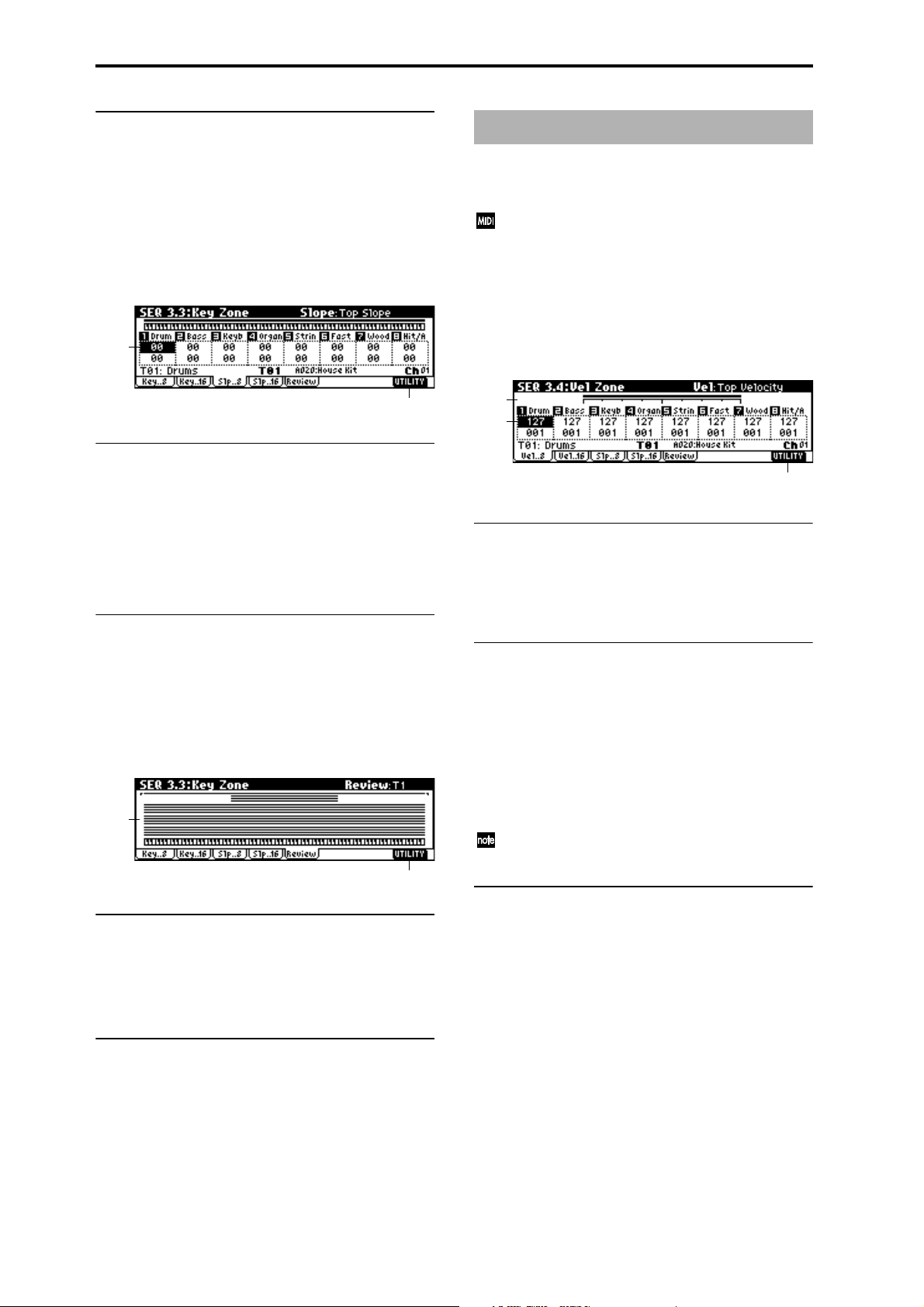
■ 3.3–1(2)c: UTILITY
☞ “Memory Status”, “Solo Selected Track”, “Rename Song”,
“Delete Song”, “Copy From Song”, “Copy From Combi”,
“Load Template Song”, “Save Template Song”, “FF/REW
Speed”, “Set Location” (1.1–1d)
3.3–3: Slp..8 (Slope T01...08)
3.3–4: Slp..16 (Slope T09...16)
3.3–3a
SEQ 3.4: Vel Zone
Top/Bottom Velocity specify the range of velocities that will
be sounded by tracks 1–8 and 9–16, and Top/Bottom Slope
specify the range over which the volume will be adjusted.
These settings do not affect MIDI transmission/reception. All note data that is received will be recorded into
the internal sequencer, and all note data from the internal sequencer or from the keyboard will be transmitted.
3.4–1: Vel..8 (Vel T01...08)
3.4–2: Vel..16 (Vel T09...16)
3.3–3b
3.3–3(4)a: Top Slope, Bottom Slope
Top Slope [00...72]
Specifies the key range (12 is one octave) from the top key
until the original volume is reached.
Bottom Slope [00...72]
Specifies the key range (12 is one octave) from the bottom
key until the original volume is reached.
■ 3.3–3(4)b: UTILITY
☞ “Memory Status”, “Solo Selected Track”, “Rename Song”,
“Delete Song”, “Copy From Song”, “Copy From Combi”,
“Load Template Song”, “Save Template Song”, “FF/REW
Speed”, “Set Location” (1.1–1d)
3.3–5: Review
3.3–5a
3.3–5b
3.4–1a
3.4–1b
3.4–1c
3.4–1(2)a: Velocity Zone Map (1)
This shows the range of velocities that will sound the currently selected track. The velocity range that will be
sounded is shown as a line, and the slope portion is grayed.
(
☞p.53 COMBI 3.4–1a)
3.4–1(2)b: Top Velocity, Bottom Velocity
Top Velocity [1…127]
Specifies the maximum velocity that will be sounded by
each track 1–16.
Bottom Velocity [1…127]
Specifies the minimum velocity that will be sounded by
each track 1–16.
For a diagram of these parameters, refer to “COMBI 3.4: EdVel Zone.”
You can also enter a value for these parameters by playing a note while you hold down the [ENTER] key.
■ 3.4–1(2)c: UTILITY
3.3–5a: Key Zone Map (All)
T1...T16
This shows the range of note data that will be sounded by
tracks 1–16. The note range that will be sounded is shown as
a line, and the slope portion is grayed.
■ 3.3–5b: UTILITY
☞ “Memory Status”, “Solo Selected Track”, “Rename Song”,
“Delete Song”, “Copy From Song”, “Copy From Combi”,
“Load Template Song”, “Save Template Song”, “FF/REW
Speed”, “Set Location” (1.1–1d)
86
☞ ““Memory Status”, “Solo Selected Track”, “Rename
Song”, “Delete Song”, “Copy From Song”, “Copy From
Combi”, “Load Template Song”, “Save Template Song”,
“FF/REW Speed”, “Set Location” (1.1–1d)
Page 97
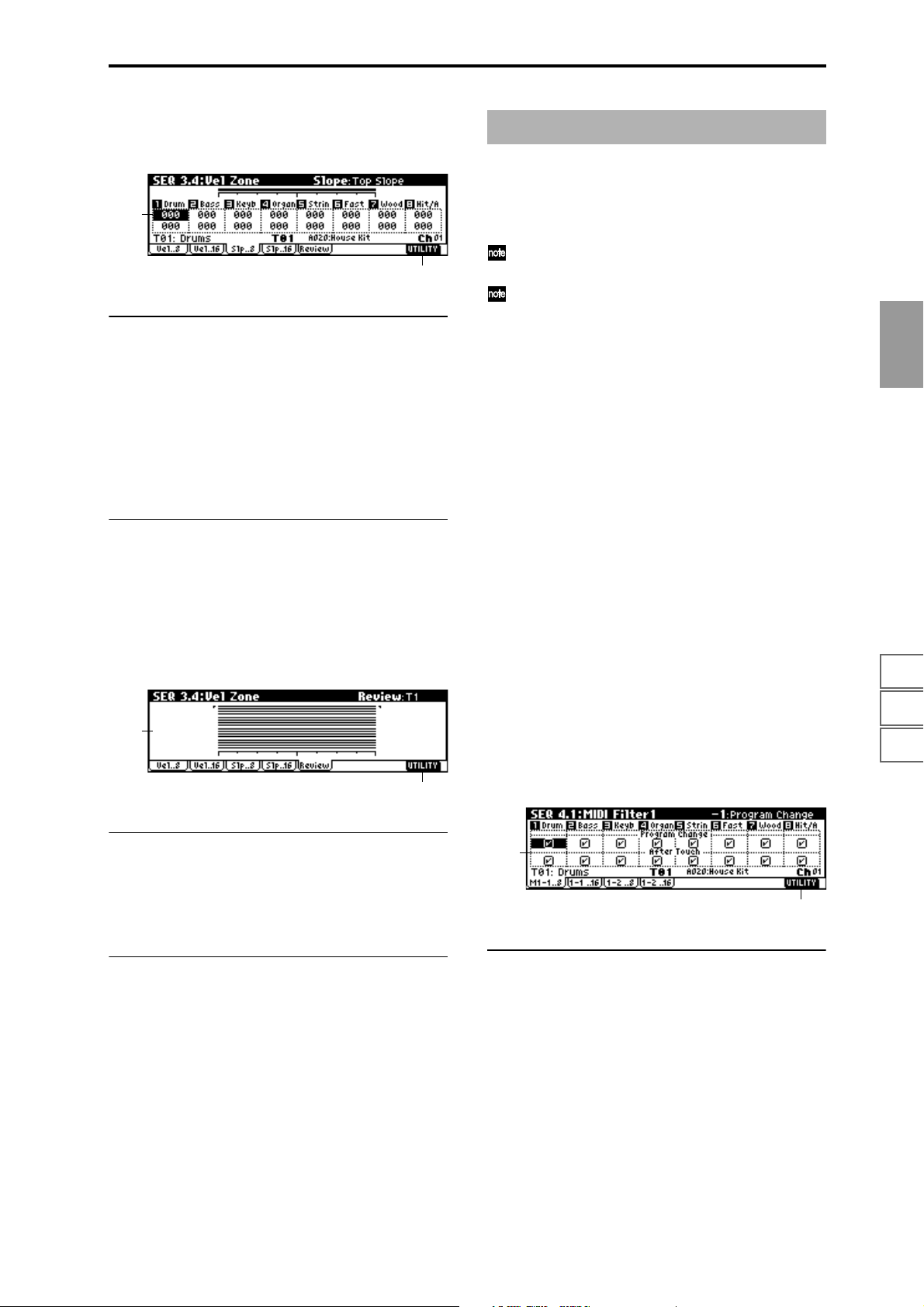
3.4–3: Slp..8 (Slope T01...08)
3.4–4: Slp..16 (Slope T09...16)
3.4–3a
3.4–3b
3.4–3(4)a: Top Slope, Bottom Slope
Top Slope [0…120]
Specifies the range of values over which the volume will be
adjusted from the top velocity until the original volume is
reached.
Bottom Slope [0…120]
Specifies the range of values over which the volume will be
adjusted from the bottom velocity until the original volume
is reached.
■ 3.4–3(4)b: UTILITY
☞ “Memory Status”, “Solo Selected Track”, “Rename Song”,
“Delete Song”, “Copy From Song”, “Copy From Combi”,
“Load Template Song”, “Save Template Song”, “FF/REW
Speed”, “Set Location” (1.1–1d)
3.4–5: Review
SEQ 4.1: MIDI Filter1
Here you can select whether or not to apply filtering to the
MIDI data received by tracks 1–16. For example even if two
tracks are receiving the same MIDI channels, one can be
made to respond to damper pedal activity while the other
does not.
These MIDI filter settings have no effect on the MIDI
messages that have already been recorded.
These MIDI filter settings do not affect the transmission
of MIDI messages that have already been recorded.
These settings affect the MIDI messages that are transmitted when you adjust program, pan, volume,
portamento and send 1/2 parameters of a track whose
“Status” (3.1–1(2)a) is set to BTH, EXT, or EX2.
On (checked): Reception of MIDI data is enabled. Tracks
whose “Status” (3.1–1(2)a) is INT or BTH will receive MIDI
messages whose channel matches and whose types are
checked. The types of effect that are checked will be applied
to the program of each track when this instrument’s controllers are operated or when MIDI data is received. (The effect
dynamic modulation function is not affected by these settings.) Settings that regulate MIDI transmission/reception of
this instrument itself are made in “MIDI Filter” (GLOBAL
2.1–1b).
If the user-assignable controllers that can be filtered in the
MIDI Filter 3 and MIDI Filter 4 pages are set to MIDI control
changes, filtering will be performed for these control
changes. In this case, any control change filtering that is
being performed in the MIDI Filter 1 and MIDI Filter 2
pages will be given priority. Furthermore, if the same control change is assigned to multiple controllers for which
there are filter settings in the MIDI Filter 3 and 4 pages,
checking any one of these will enable that control change.
Off (unchecked): Reception of MIDI data is disabled.
SEQ
1.11.22.12.22.33.13.23.33.44.14.24.34.45.15.26.16.26.36.4
3.4–5a
3.4–5b
3.4–5a: Velocity Zone Map (All)
T1...T16
This shows the range of velocity that will be sounded by
tracks 1–16. The note range that will be sounded is shown as
a line, and the slope portion is grayed.
■ 3.4–5b: UTILITY
☞ “Memory Status”, “Solo Selected Track”, “Rename Song”,
“Delete Song”, “Copy From Song”, “Copy From Combi”,
“Load Template Song”, “Save Template Song”, “FF/REW
Speed”, “Set Location” (1.1–1d)
4.1–1: M1–1..8 (MIDI Filter1–1 T01...08)
4.1–2: 1–1..16 (MIDI Filter1–1 T09...16)
4.1–1a
4.1–1b
4.1–1(2)a: Program Change, After Touch
Program Change [Off, On]
Specifies whether or not MIDI program change messages
will be received.
After Touch [Off, On]
Specifies whether or not MIDI after touch messages will be
received.
7.17.27.3
87
Page 98
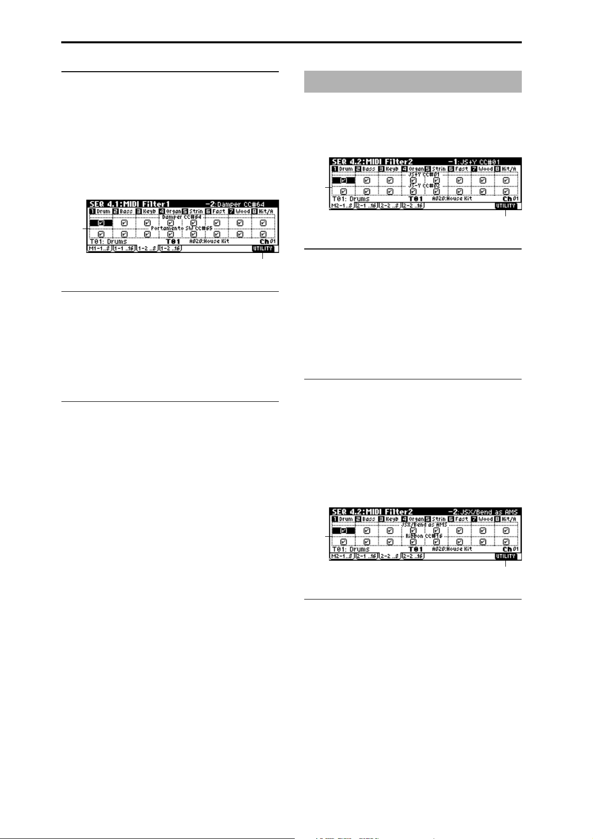
■ 4.1–1(2)b: UTILITY
☞ “Memory Status”, “Solo Selected Track”, “Rename Song”,
“Delete Song”, “Copy From Song”, “Copy From Combi”,
“Load Template Song”, “Save Template Song”, “FF/REW
Speed”, “Set Location” (1.1–1d)
4.1–3: 1–2..8 (MIDI Filter1–2 T01...08)
SEQ 4.2: MIDI Filter2
4.2–1: M2–1..8 (MIDI Filter2–1 T01...08)
4.2–2: 2–1..16 (MIDI Filter2–1 T09...16)
4.1–4: 1–2..16 (MIDI Filter1–2 T09...16)
4.1–3a
4.1–3b
4.1–3(4)a: Damper, Portamento SW
Damper CC#64 [Off, On]
Specifies whether or not MIDI control change message #64
Hold (damper pedal) will be received.
Portamento SW CC#65 [Off, On]
Specifies whether or not MIDI control change message #65
Portamento On/Off will be received.
4.1–3(4)b: UTILITY
☞ “Memory Status”, “Solo Selected Track”, “Rename Song”,
“Delete Song”, “Copy From Song”, “Copy From Combi”,
“Load Template Song”, “Save Template Song”, “FF/REW
Speed”, “Set Location” (1.1–1d)
4.2–1a
4.2–1b
4.2–1(2)a: JS+Y, JS-Y
JS+Y CC#01 [Off, On]
Specifies whether or not MIDI control message #1 (the +Y
axis of this instrument’s joystick, or assigned to B-mode of
the REAL-TIME CONTROL knobs [1]–[4]) will be received.
JS-Y CC#02 [Off, On]
Specifies whether or not MIDI control message #2 (the –Y
axis of this instrument’s joystick, or assigned to B-mode of
the REAL-TIME CONTROL knobs [1]–[4]) will be received.
■ 4.2–1(2)b: UTILITY
☞ “Memory Status”, “Solo Selected Track”, “Rename Song”,
“Delete Song”, “Copy From Song”, “Copy From Combi”,
“Load Template Song”, “Save Template Song”, “FF/REW
Speed”, “Set Location” (1.1–1d)
4.2–3: 2–2..8 (MIDI Filter2–2 T01...08)
4.2–4: 2–2..16 (MIDI Filter2–2 T09...16)
4.2–3a
4.2–3b
4.2–3(4)a: JSX/Bend as AMS, Ribbon
JSX/Bend as AMS [Off, On]
Allow incoming MIDI pitch bend messages (the X-axis of
this instrument’s joystick) to control the AMS (
Modulation Source”) that is specified for JS X. (This is not a
reception filter for MIDI pitch bend messages.)
☞“Alternate
88
Page 99
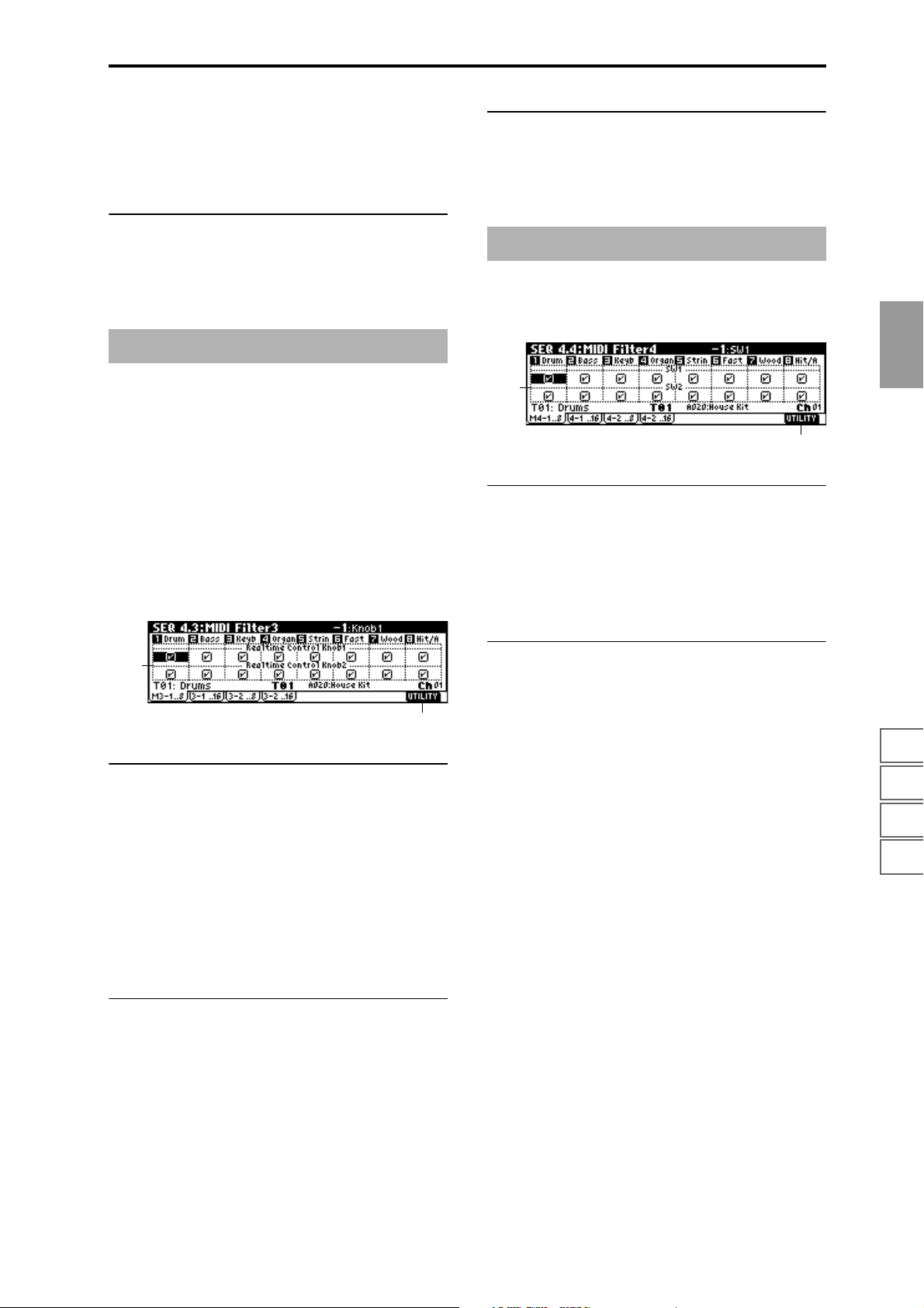
Ribbon CC#16 [Off, On]
Specifies whether MIDI control change message #16 (speci-
fied as the B-mode assignment of REAL-TIME CONTROLS
knobs [1]–[4], or the ribbon controller of a TRITON etc.) will
be received.
■ 4.2–3(4)b: UTILITY
☞ “Memory Status”, “Solo Selected Track”, “Rename Song”,
“Delete Song”, “Copy From Song”, “Copy From Combi”,
“Load Template Song”, “Save Template Song”, “FF/REW
Speed”, “Set Location” (1.1–1d)
■ 4.3–1(2)b, 4.3–3(4)b: UTILITY
☞ “Memory Status”, “Solo Selected Track”, “Rename Song”,
“Delete Song”, “Copy From Song”, “Copy From Combi”,
“Load Template Song”, “Save Template Song”, “FF/REW
Speed”, “Set Location” (1.1–1d)
SEQ 4.4: MIDI Filter4
4.4–1: M4–1..8 (MIDI Filter4–1 T01...08)
4.4–2: 4–2..16 (MIDI Filter4–1 T09...16)
SEQ 4.3: MIDI Filter3
Specifies whether the A- and B-mode operations of REALTIME CONTROLS knobs [1]–[4] will be received. MIDI control messages are fixed as the A mode operation of each
knob. In B mode the knobs correspond to the messages you
assign in the 2.2: Controller Controls page.
4.3–1: M3–1..8 (MIDI Filter3–1 T01...08)
4.3–2: 3–1..16 (MIDI Filter3–1 T09...16)
4.3–3: 3–2..8 (MIDI Filter3–2 T01...08)
4.3–4: 3–2..16 (MIDI Filter3–2 T09...16)
4.3–1a
4.3–1b
4.3–1(2)a: Real-time Control Knob 1, 2
SEQ
4.4–1a
1.11.22.12.22.33.13.23.33.44.14.24.34.45.15.26.16.26.36.4
4.4–1b
4.4–1(2)a: SW1, SW2
SW1, SW2 [Off, On]
Specifies whether or not the effect of the [SW1] and [SW2]
keys will be received. The function of these keys can be set
in SEQ 2.2: Controller page. This is valid when the switches
are set to SW1 Mod.:CC#80, SW2 Mod.:CC#81 or
Porta.SW:CC#65.
■ 4.4–1(2)b: UTILITY
☞ “Memory Status”, “Solo Selected Track”, “Rename Song”,
“Delete Song”, “Copy From Song”, “Copy From Combi”,
“Load Template Song”, “Save Template Song”, “FF/REW
Speed”, “Set Location” (1.1–1d)
Knob1 [Off, On]
Specifies whether or not the A mode [1] knob MIDI control
change message #74 (this instrument’s low pass filter cutoff
frequency) and the B mode [1] knob MIDI control change
message will be received.
Knob2 [Off, On]
Specifies whether or not the A-mode [2] knob MIDI control
change message #71 (this instrument’s low pass filter reso-
nance or high pass filter cutoff frequency) and the B mode
[2] knob MIDI control change message will be received.
4.3–3(4)a: Real-time Control Knob 3, 4
Knob3 [Off, On]
Specifies whether or not the A mode [3] knob MIDI control
change message #79 (this instrument’s filter EG intensity)
and the B mode [3] knob MIDI control change message will
be received.
Knob4 [Off, On]
Specifies whether or not the A mode [4] knob MIDI control
change message #72 (the release time of this instrument’s fil-
ter and amp EG’s) and the B mode [4] knob MIDI control
change message will be received.
7.17.27.3
89
Page 100

4.4–3: 4–2..8 (MIDI Filter4–2 T01...08)
4.4–4: 4–2..16 (MIDI Filter4–2 T09...16)
4.4–3a
4.4–3b
4.4–3(4)a: Foot Pedal/Switch, Other Control
Change
Foot Pedal/Switch [Off, On]
Specifies whether or not the effect of the ASSIGNABLE
PEDAL/SWITCH will be received. The function of this
switch is set in GLOBAL 6.1: Controller. This ˇ valid when
the switch is set to a MIDI control change.
Other Control Change [Off, On]
Specifies whether or not MIDI controller messages other
than those included in MIDI Filter 1–4 will be received.
4.4–3(4)b: UTILITY
☞ “Memory Status”, “Solo Selected Track”, “Rename Song”,
“Delete Song”, “Copy From Song”, “Copy From Combi”,
“Load Template Song”, “Save Template Song”, “FF/REW
Speed”, “Set Location” (1.1–1d)
SEQ 5.1: RPPR
On this instrument you can use preset patterns P000–149,
and user patterns U00–99. One song can contain up to one
hundred user patterns. Preset patterns suitable for use in a
drum track are provided in memory, and can be selected
from any song.
Preset patterns cannot be edited, but you may copy a preset
pattern to a user pattern, and edit.
User patterns can be created by real-time recording, step
recording, the Get From Track command (obtaining data
from a track), or the Copy Pattern command (copying from
another pattern) (
These patterns can be assigned to each key by the RPPR
(Real-time Pattern Play/Recording) function and played by
pressing a single key, and the resulting performance can be
recorded on the sequencer (
5.1–1: Pattern
If you wish to record pattern data, use “Pattern” and ˇattern
Select” to select a user pattern and pattern number. Next,
use the “Pattern Parameter” page menu command to set the
number of measures in the pattern and its time signature.
Then you can perform real-time recording in the Pattern
Edit tab, or step recording by using the “Step Recording
(Loop)” page menu command. Finally, use page menu commands as desired to perform event editing or other types of
editing.
5.1–1a
5.1–1b
☞BG p.67).
☞5.1–2: RPPR Setup page).
5.1–1c
5.1–1a: Location, Song Select, Track Select
Location
This shows the current location of the selected pattern, in
measure units.
Select [000…199: name]
Selects the song that you wish to use. (☞1.1–1b)
Track Select [T01…T16: name]
Selects the track that will record/play the pattern data.
(
☞1.1–1c)
The program bank, number, and name of the selected track
will be displayed at the right.
90
 Loading...