

Page 1
1E
Page 2
▼ 5–1: Page Menu Command
0–1A
5–1A
5–1A: Swap LFO 1&2
1 2 3
Parameters in the LCD display screen “ ”
About this manual
Parameters displayed in the LCD screen are enclosed in
double quotation marks “ ”.
This “Parameter Guide” contains explanations and other
information regarding the operations of the parameters and
settings on the TRITON STUDIO. The explanations are organized by mode, and page. Explanations and other information on the effects and their parameters are also provided for
each effect.
Refer to this guide when an unfamiliar parameter appears in
the display, or when you need to know more about a particular function.
Boldface type
Parameter values are printed in boldface type.
Content that is of particular importance is also printed in
boldface type.
Procedure steps
Steps in a procedure are listed as
☞
p.
■
,
☞■
–
1
2
3
...
...
■
These indicate pages or parameter numbers to which you
can refer.
Symbols , , , , ,
Conventions in this manual
References to the TRITON STUDIO
The TRITON STUDIO is available in 88-key, 76-key and 61key models, but both models are referred to without distinction in this manual as “the TRITON STUDIO.” Illustrations
of the front and rear panels in this manual show the 61-key
model, but the illustrations apply equally to the 88-key and
76-key models.
Abbreviations for the manuals BG, PG, VNL
References to the manuals included with the TRITON STUDIO are abbreviated as follows in this document.
BG: Basic Guide
PG: Parameter Guide
VNL: Voice Name List
These symbols respectively indicate cautions, advice, MIDIrelated explanations, a parameter that can be selected as an
alternate modulation source, a parameter that can be
selected as a dynamic modulation source, and a parameter
that can use the BPM/MIDI Sync function.
Example screen displays
The values of the parameters shown in the example screens
of this manual are only for explanatory purposes, and may
not necessary match the values that appear in the LCD
screen of your instrument.
MIDI-related explanations
CC# is an abbreviation for Control Change Number.
In explanations of MIDI messages,
brackets [ ]
always indicate hexadecimal numbers.
numbers in square
Keys and knobs [ ]
References to the switches, dials, and knobs on the TRITON
STUDIO’s panel are enclosed in square brackets [ ]. References to
buttons or tabs indicate objects in the LCD display
screen.
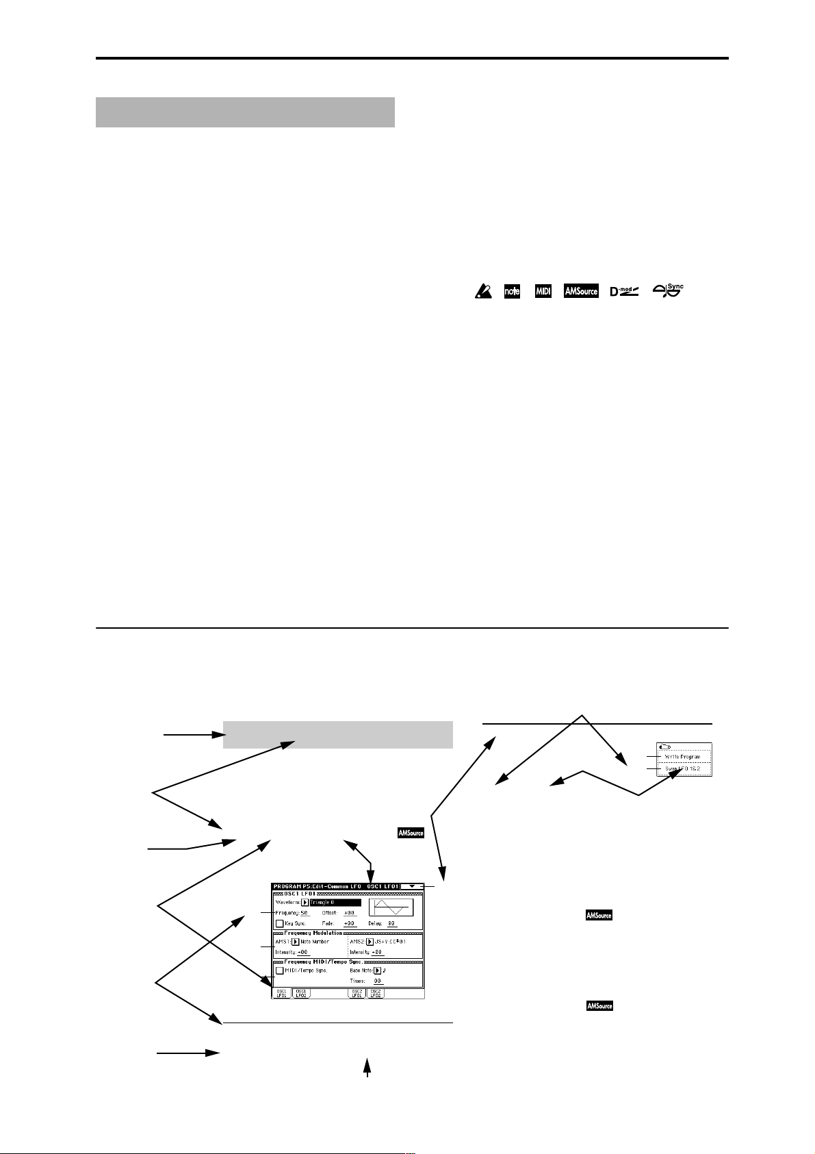
How to read the “Parameter Guide”
(example)
Mode name
Page No.
Tab No.
Tab name
Parameter
number
Parameter
name
Program P5: Edit-Common LFO
Here you can make settings for the LFO that can be used to
cyclically modulate the Pitch, Filter, and Amp of oscillators 1
and 2. There are two LFO units for each oscillator. By setting
the LFO1 or LFO2 Intensity to a negative (–) value for Pitch,
Filter, or Amp, you can invert the LFO waveform.
5–1: OSC1 LFO1 ( )
Make settings for the “OSC1 LFO1,” which is the first LFO
that can be used for oscillator 1.
5–1a
5–1b
5–1c
5–1a: OSC1 LFO1
Waveform [Triangle 0…Random6 (Vector)]
Select the LFO waveform.
Page menu command
Page name
5–1
Range of possible
parameter values
Page menu command No.
Page menu
command name
This command exchanges the settings of LFO1 and 2. If LFO2
has been selected as Frequency Modulation AMS1 or 2 of
LFO1, that setting will be cancelled for LFO2 after the LFO1
and 2 settings have been exchanged. If this is selected from
the OSC1 LFO1 or OSC1 LFO2 tab, the LFO1 and LFO2 of
OSC1 will be exchanged.
1 Select this command to open the dialog box.
2 Press the OK button.
5–2: OSC1 LFO2
Here you can make settings for the OSC1 LFO2, which is the
second LFO that can be applied to oscillator 1. (☞“5–1: OSC1
LFO1”) However in “Frequency Modulation” (5–1b), the
LFO cannot be selected as a modulation source in “AMS1” or
“AMS2.”
5–3: OSC2 LFO1
This can be used when “Oscillator Mode” (1–1a) is set to
Double.
Here you can make settings for the OSC2 LFO1, which is the
first LFO that can be applied to oscillator 2. (☞“5–1: OSC1
LFO1”)
iii
Page 3
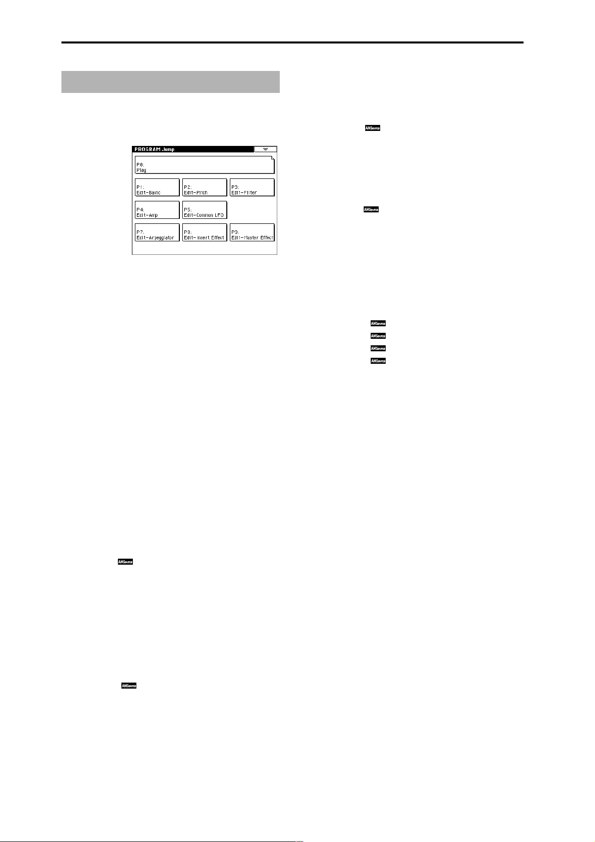
Table of Contents
1. Program mode. . . . . . . . . . . . .1
Program P0: Play ......................................... 1
Select and play programs.
0–1: Perf. Edit
0–2: Arpeggio
0–3: Sampling
Program P1: Edit–Basic.................................. 7
Make basic oscillator settings and scale settings etc.
1–1: Program Basic
1–2: OSC Basic
1–3: Velo. Zone
1–4: Controller
Program P2: Edit–Pitch .................................12
Make pitch-related settings for oscillators 1 and 2.
2–1: OSC1 P.Mod
2–2: OSC2 P.Mod
2–3: Pitch EG
Program P3: Edit–Filter.................................16
Make filter settings for oscillators 1 and 2.
3–1: Filter1
3–2: Filter1 Mod.
3–3: Filter1 LFO Mod.
3–4: Filter1 EG
3–5: Filter2
Select and play programs; use the
Performance Editor for simple editing
Arpeggio pattern selection and settings
Perform sampling; make settings for
audio inputs etc.
Oscillator settings for Single/Double/
Drums, Poly/Mono, scale etc.
Specify the multisample for oscillators 1
and 2
............................................................9
Velocity zone settings
[SW1] and [SW2] key functions;
REALTIME CONTROLS [1]–[4] knob Bmode functions
Specify oscillator 1 pitch modulation via
key position or controllers
Specify oscillator 2 pitch modulation via
key position or controllers
Pitch EG settings
Filter 1 (for oscillator 1) type, cutoff
frequency, and resonance settings
Keyboard tracking and controller settings
to modulate the filter 1 cutoff frequency
....................................................................17
Filter 1 LFO settings to modulate the filter
1 cutoff frequency
Filter 1 EG settings
Filter 2 (for oscillator 2) type, cutoff
frequency, and resonance settings
.........................................4
.............................11
........................................12
......................12
......................14
......................................14
....................................18
...................................19
...1
..................7
........16
........21
.3
3–6: Filter2 Mod.
3–7: Filter2 LFO Mod.
3–8: Filter2 EG
Keyboard tracking and controller settings
to modulate the filter 2 cutoff frequency
....................................................................21
Filter 2 LFO settings to modulate the filter
2 cutoff frequency
Filter 2 EG settings
....................................21
...................................21
Program P4: Edit–Amp..................................21
Make amp settings for oscillators 1 and 2.
4–1: Amp1 Level/Pan
4–2: Amp1 Mod.
4–3: Amp1 EG
4–4: Amp2 Level/Pan
4–5: Amp2 Mod.
4–6: Amp2 EG
Oscillator 1 volume and pan settings
Keyboard tracking and controller settings
to modulate amp 1
Amp 1 EG settings
Oscillator 2 volume and pan settings
Keyboard tracking and controller settings
to modulate amp 2
Amp 2 EG settings
...................................22
...................................23
...................................24
...................................24
....21
....24
Program P5: Edit–Common LFO....................... 25
Make settings for the general purpose LFOs used to cyclically modulate the pitch, filter, and amp of oscillators 1
and 2.
5–1: OSC1 LFO1
5–2: OSC1 LFO2
5–3: OSC2 LFO1
5–4: OSC2 LFO2
OSC1 LFO1 (for oscillator 1) settings
OSC1 LFO2 (for oscillator 1) settings
OSC2 LFO1 (for oscillator 2) settings
OSC2 LFO2 (for oscillator 2) settings
....25
....26
....26
....26
Program P7: Edit–Arpeggiator......................... 26
Make settings for the arpeggiator.
7–1: Arpeg. Setup
7–2: Scan Zone
Select an arpeggio pattern and make
.......................................................26
settings
Specify the note and velocity ranges that
will operate the arpeggiator
...................28
Program P8: Edit–Insert Effect......................... 28
Specify the oscillator output bus, and make insert effect
settings.
8–1: Routing
8–2: Insert FX
8–3: IFX 1
8–4: IFX 2
8–5: IFX 3
8–6: IFX 4
8–7: IFX 5
Specify the oscillator output bus and set
the send levels to the master effects
Select insert effects and turn them on/off,
and make chain settings
Parameter settings for IFX1
Parameter settings for IFX2
Parameter settings for IFX3
Parameter settings for IFX4
Parameter settings for IFX5
..........................29
......28
....................30
....................30
....................30
....................30
....................30
Program P9: Edit–Master Effect ....................... 31
Make master effect and master EQ settings.
9–1: Master FX
9–2: MFX 1
9–3: MFX 2
9–4: Master EQ
Select master effects and turn them on/
off, and make chain settings
Parameter settings for MFX1
Parameter settings for MFX2
Parameter settings for master EQ
...................31
..................32
..................32
..........32
iv
Page 4
2. Combination mode. . . . . . . . .33
Combination P0: Play................................... 33
Select and play combinations.
0–1: Prog. Select
0–2: Mixer
0–3: Arpegg. A
0–4: Arpegg. B
0–5: Sampling
Select a program for each timbre
Specify pan and level
Select an arpeggio pattern and make
settings for arpeggiator A
Select an arpeggio pattern and make
settings for arpeggiator B
Perform sampling; make audio input
settings etc.
................................................36
...............................35
Combination P1: Edit–Program/Mixer................ 37
Select the program for each timbre, and specify pan and
level.
1–1: Program/Mixer
Specify program, pan, and level of each
timbre
........................................................37
Combination P2: Edit–Trk Param ..................... 38
Set various parameters for each timbre.
2–1: MIDI Channel
2–2: OSC
2–3: Pitch
2–4: Other
Specify MIDI channel and status for each
timbre
........................................................38
Make settings such as mono/poly and
portamento for each timbre
Make pitch-related settings such as
transpose and bend range for each timbre
....................................................................39
Make delay and scale settings for each
timbre
........................................................40
...........33
.......................36
........................36
....................38
Combination P7: Edit–Arp...............................44
Make settings for arpeggiators A and B.
7–1: Setup
7–2: Arpegg. A
7–3: Arpegg. B
7–4: Scan Zone
Assign arpeggiators to each timbre
Select an arpeggio pattern and make
settings for arpeggiator A
Select an arpeggio pattern and make
settings for arpeggiator B
Specify the ranges of notes and velocities
that will operate the arpeggiator
........................45
.......44
.......................45
............45
Combination P8: Edit–Insert FX........................46
Specify the output bus for each timbre, and make insert
effect settings.
8–1: Routing
8–2: Insert FX
8–3: IFX 1
8–4: IFX 2
8–5: IFX 3
8–6: IFX 4
8–7: IFX 5
Specify the output bus and master effect
send levels for each timbre
Select insert effects, turn them on/off, and
make chain settings
Parameter settings for IFX1
Parameter settings for IFX2
Parameter settings for IFX3
Parameter settings for IFX4
Parameter settings for IFX5
......................46
..................................47
.....................47
.....................47
.....................47
.....................47
.....................47
Combination P9: Edit–Master FX ......................48
Make settings for the master effects and master EQ.
9–1: Master FX
9–2: MFX 1
9–3: MFX 2
9–4: Master EQ
Select the master effects, turn them on/
off, and make chain settings
Parameter settings for MFX1
Parameter settings for MFX2
Parameter settings for master EQ
...................48
..................48
..................48
..........48
ProgramCombinationSequencerSampling
Song PlayGlobalDiskEffectAppendices
Combination P3: Edit–MIDI Filter..................... 40
Specify MIDI message reception filtering for each timbre.
3–1: MIDI 1
3–2: MIDI 2
3–3: MIDI 3
3–4: MIDI 4
Program changes, aftertouch etc.
Joystick, ribbon controller
Realtime control knobs
SW1/2, foot controller etc.
............................41
...........40
.......................41
......................41
Combination P4: Edit–Zone/Ctrl....................... 42
Specify the key range and controllers for each timbre.
4–1: Key Z
4–2: Vel Z
4–3: MOSS Setup
4–4: Controller
Specify the key zone sounded by each
timbre
........................................................42
Specify the range of velocities sounded by
each timbre
Displayed if the EXB-MOSS option is
installed; set EXB-MOSS parameters
Specify the function of the [SW1] and
[SW2] keys, and B-mode functions of the
REALTIME CONTROLS [1]–[4] knobs
................................................42
.....43
.43
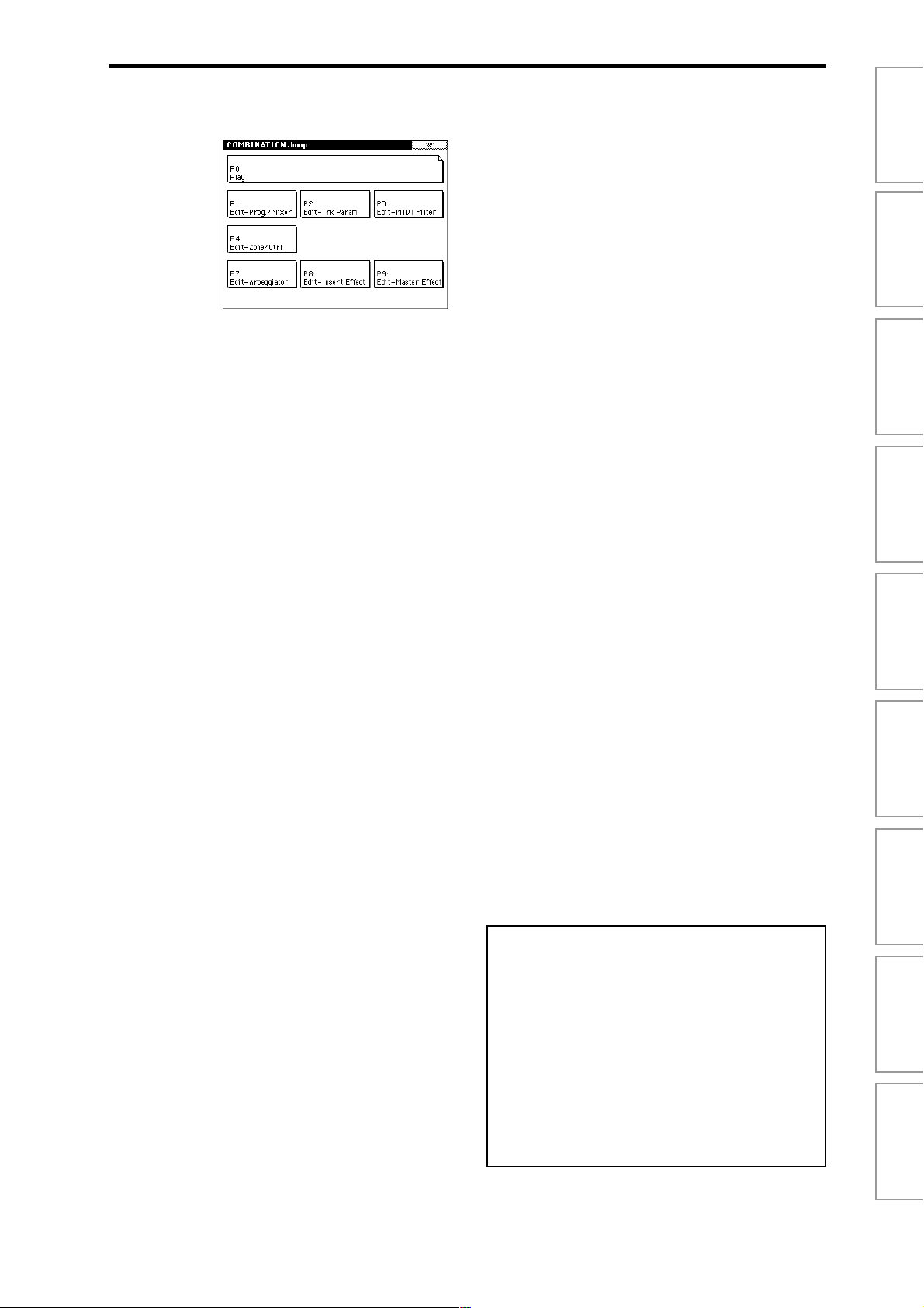
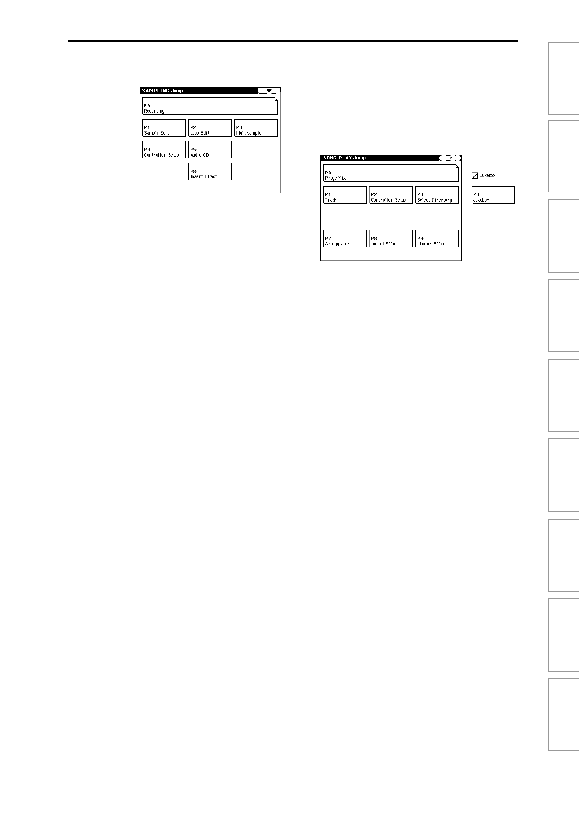
About the Jump pages
The LCD screens shown here are the Jump pages for each
mode.
The Jump page is a page menu that lets you access the various pages within each mode.
Here’s how to access the Jump page, and select the desired
page.
• Press the [MENU] key to access the Jump page. In the
LCD screen, press the page that you want to select, or
press the numeric key [0]–[9] corresponding to the
number of the desired page. (
• Alternatively, you can hold down the [MENU] key and
press the numeric key [0]–[9] corresponding to the
number of the desired page.
☞
BG p.16)
v
Page 5

3. Sequencer mode . . . . . . . . . .49
Sequencer P0: Play/Rec ................................49
Make settings for playing/recording a song, and select the
program etc. used for each track.
0–1: Prog. 1–8
0–2: Prog. 9–16 ....................................................................49
0–3: Mixer 1–8
0–4: Mixer 9–16 ....................................................................55
0–5: PlyLoop 1–8
0–6: PlyLoop 9–16 ....................................................................55
0–7: Sampling
0–8: Preference
Program selection, mute, and solo settings
for each track
Pan and volume settings for each track
Loop track settings for each track
Settings for sampling and audio input etc.
....................................................................56
Select the realtime recording method, and
you can make metronome settings
............................................49
..........55
........57
Sequencer P4: Zone/Ctrl................................66
Specify the note range and controllers for each track.
4–1: Key Z 1–8
4–2: Key Z 9–16 ....................................................................66
4–3: Vel Z 1–8
4–4: Vel Z 9–16 ....................................................................67
4–5: MOSS 1–8
4–6: MOSS 9–16 ....................................................................67
4–7: Controller
Specify the range of keys sounded by each
track
...........................................................66
Specify the range of velocities sounded by
each track
Displayed if the EXB-MOSS option is
installed; set EXB-MOSS parameters
Specify the function of the [SW1] and
[SW2] keys, and B-mode functions of the
REALTIME CONTROLS [1]–[4] knobs
..................................................67
.....67
.67
Sequencer P5: Track Edit............................... 68
Perform track editing and step recording.
5–1: T rack Edit
55
5–2: T rack Name
Track editing operations such as Copy or
Delete, and step recording
Edit the name of each track
......................68
....................75
Sequencer P6: Pattern/RPPR .......................... 76
Record and edit patterns, and make RPPR settings.
6–1: Pattern Edit
6–2: Pattern Name
6–3: RPPR Setup
Record a pattern, and perform pattern
editing such as Copy or Delete
Edit the name of a pattern
RPPR settings
............................................79
..............76
.......................78
Sequencer P1: Cue List .................................59
Create and play a cue list for playing a succession of songs.
1–1: Cue List
Create and play back a cue list
...............59
Sequencer P2: Trk Param...............................62
Set various parameters for each timbre.
2–1: MIDI Ch 1–8
2–2: MIDI Ch 9–16 ....................................................................62
2–3: OSC 1–8
2–4: OSC 9–16 ....................................................................63
2–5: Pitch 1–8
2–6: Pitch 9–16 ....................................................................63
2–7: Other 1–8
2–8: Other 9–16 ....................................................................64
MIDI channel and status settings for each
track
...........................................................62
Mono/poly and portamento settings etc.
for each track
Pitch-related settings (transpose, pitch
bend range etc.) for each track
Delay and scale settings for each track
............................................63
...............63
.64
Sequencer P3: MIDI Filter ..............................65
Specify MIDI message reception filtering for each track.
3–1: MIDI 1 1–8
3–2: MIDI 1 9–16 ....................................................................65
3–3: MIDI 2 1–8
3–4: MIDI 2 9–16 ....................................................................65
3–5: MIDI 3 1–8
3–6: MIDI 3 9–16 ....................................................................65
3–7: MIDI 4 1–8
3–8: MIDI 4 9–16 ....................................................................66
Program changes, aftertouch etc.
Joystick, ribbon controller
Realtime control knobs
SW1/2, foot controller etc.
...........................65
..........65
......................65
.....................66
Sequencer P7: Arpeggiator............................. 81
Make settings for arpeggiators A and B.
7–1: Setup 1–8
7–2: Setup 9–16 ....................................................................81
7–3: Arpegg. A
7–4: Arpegg. B
7–5: Scan Zone
Assign an arpeggiator to each track
Select an arpeggio pattern and make
settings for arpeggiator A
Select an arpeggio pattern and make
settings for arpeggiator B
Specify the range of notes and velocities
that will operate the arpeggiator
.......................82
........................82
......81
...........82
Sequencer P8: Insert Effect ............................83
Specify the bus for the output of each track, and make
insert effect settings.
8–1: Routing 1–8
8–2: Routing 9–16 ....................................................................83
8–3: Insert FX
8–4: IFX 1
8–5: IFX 2
8–6: IFX 3
8–7: IFX 4
8–8: IFX 5
Specify the bus and master effect send
levels for the output of each track
Select insert effects and turn them on/off,
and make chain settings
Parameter settings for IFX1
Parameter settings for IFX2
Parameter settings for IFX3
Parameter settings for IFX4
Parameter settings for IFX5
..........................84
.........83
....................85
....................85
....................85
....................85
....................85
Sequencer P9: Master Effect........................... 85
Make master effect and master EQ settings.
9–1: Master FX
9–2: MFX 1
9–3: MFX 2
9–4: Master EQ
Select master effects and turn them on/
off, and make chain settings
Parameter settings for MFX1
Parameter settings for MFX2
Parameter settings for master EQ
...................85
..................86
..................86
..........86
vi
Page 6
4. Sampling mode . . . . . . . . . . .87
Sampling P0: Recording ............................... 88
Make sample recording settings such as input level, and
basic settings for multisamples and samples.
0–1: Recording
0–2: Input/Setup
0–3: Preference
0–4: Memory Status
Sampling P1: Sample Edit ............................100
Edit sample data (waveform data), and perform editing
operations such as Copy and Rate Convert.
1–1: Sample Edit
Sampling P2: Loop Edit................................107
Specify the region of the sample that will be played, make
loop playback settings, and perform editing operations
such as Time Slice and Time Stretch.
2–1: Loop Edit
Basic settings such as selecting a
multisample and sample, and adjusting
the final input level
Audio input settings, and recording setup
....................................................................96
Settings for creating indexes
View the amount of remaining sample
memory (RAM), and the remaining
number of multisamples and samples
Edit sample data (waveform data)
Loop playback settings and editing
..................................88
...................98
..99
......100
.....107
8–5: IFX 3
8–6: IFX 4
8–7: IFX 5
Parameter settings for IFX3
Parameter settings for IFX4
Parameter settings for IFX5
...................122
...................122
...................122
5. Song Play mode . . . . . . . . . 123
Song Play P0: Prog/Mix ............................... 123
Select SMF data and play it back.
0–1: Prog. 1–8
0–2: Prog. 9–16 ..................................................................123
0–3: Mixer 1–8
0–4: Mixer 9–16 ..................................................................125
0–5: Preference
Song Play P1: Track ................................... 126
Specify the status and scale for each track.
1–1: Status 1–8
1–2: Status 9–16 ..................................................................126
1–3: MOSS 1–8
1–4: MOSS 9–16 ..................................................................126
Select the program for each track
Set pan and volume for each track
Settings for consecutive playback of SMF
data, and metronome settings
Status and scale settings
Displayed if the EXB-MOSS option is
installed; set EXB-MOSS parameters
.........123
.......125
..............125
........................126
...126
ProgramCombinationSequencerSampling
Song PlayGlobalDiskEffectAppendices
Sampling P3: Multisample............................117
Edit a multisample. Assign samples, and specify zones
and original keys.
3–1: Multisample
3–2: Preference
Edit multisamples
Settings for creating indexes
..................................117
.................119
Sampling P4: Controller Setup.......................119
Make controller settings.
4–1: Controller Setup
Specify the function of the [SW1] and [SW2]
keys, and B-mode functions of the
REALTIME CONTROLS [1]–[4] knobs
...119
Sampling P5: Audio CD................................120
Play back an audio CD, and rip samples from an audio
CD.
5–1: Audio CD
Play back an audio CD and rip
............120
Sampling P8: Insert Effect ............................122
Specify the bus for the sample output, and make insert
effect settings.
8–1: Routing
8–2: Insert FX
8–3: IFX 1
8–4: IFX 2
Specify the bus for the sample
output
......................................................122
Select insert effects, turn them on/off, and
make chain settings
Parameter settings for IFX1
Parameter settings for IFX2
................................122
..................122
..................122
Song Play P2: Controller Setup ...................... 127
Make controller settings.
2–1: Controller Setup
Specify the function of the [SW1] and [SW2]
keys, and B-mode functions of the
REALTIME CONTROLS [1]–[4] knobs
...127
Song Play P3: Select Directory/Jukebox............128
Select the directory that contains the SMF you want to
play. If “Jukebox” is checked, you can create a jukebox list.
3–1: Select Directory
3–1: Jukebox
Select the directory that contains the SMF
you want to play
Create a jukebox list
.....................................128
...............................128
Song Play P7: Arpeggiator............................ 129
Make settings for arpeggiators A and B.
7–1: Setup 1–8
7–2: Setup 9–16 ..................................................................129
7–3: Arpegg. A
7–4: Arpegg. B
7–5: Scan Zone
Assign an arpeggiator to each track
Select an arpeggio pattern and make
settings for arpeggiator A
Select an arpeggio pattern and make
settings for arpeggiator B
Specify the range of notes and velocities
that will operate the arpeggiator
......................130
.....129
.....................130
..........130
vii
Page 7

Song Play P8: Insert Effect ........................... 131
Specify the bus for the output of each track, and make
insert effect settings.
8–1: Routing 1–8
8–2: Routing 9–16 ..................................................................131
8–3: Insert FX
8–4: IFX 1
8–5: IFX 2
8–6: IFX 3
8–7: IFX 4
8–8: IFX 5
Specify the bus and the master effect send
levels for the output of each
track
.........................................................131
Select insert effects, turn them on/off, and
make chain settings
Parameter settings for IFX1
Parameter settings for IFX2
Parameter settings for IFX3
Parameter settings for IFX4
Parameter settings for IFX5
...............................132
..................132
..................132
..................132
..................132
..................132
Song Play P9: Master Effect.......................... 133
Make settings for the master effects and master EQ.
9–1: Master FX
9–2: MFX1
9–3: MFX2
9–4: Master EQ
Select the master effects, turn them on/
off, and make chain settings
Parameter settings for MFX1
Parameter settings for MFX2
Parameter settings for master EQ
.................133
................133
................133
........133
6. Global mode . . . . . . . . . . . .135
Global P0: Basic Setup.................................135
Make basic settings that affect the entire TRITON STUDIO,
and make AUDIO INPUT settings for other than Sampling
mode. If the EXB-mLAN option is installed, make settings
for mLAN input/output.
0–1: Basic
0–2:
System Preference Bank map, system lock, and memory
0–3: Input/Sampling
0–4: mLAN Output
0–5: mLAN Input
Master tune, key transpose, effect global
switch, and auto arpeggiator on/off
settings
.....................................................135
protect settings
Audio input settings for other than
Sampling mode
Audio and MIDI output settings to an
external mLAN device (EXB-mLAN
option)
Audio and MIDI input settings from an
external mLAN device (EXB-mLAN
option)
.......................................137
......................................139
.....................................................140
.....................................................141
Global P1: MIDI .........................................142
Make MIDI settings for the entire TRITON STUDIO.
1–1: MIDI
Settings such as global MIDI channel,
MIDI clock, and MIDI filter
..................142
Global P2: Controller...................................146
Make settings for the damper pedal and assignable foot
switch/pedal.
2–1: Controller
Damper pedal and assignable foot
switch/pedal settings
............................146
Global P3: User Scale..................................146
Create user octave scales and user all note scales.
3–1: User Scale
Create user scales
...................................146
Global P4: Category Name ............................147
Assign names to categories.
4–1: Program Cat.
4–2: Comb Cat.
Specify program category names
Specify combination category names
.........147
..147
Global P5: Drum Kit ....................................148
Edit or create drum kits.
5–1: Sample Setup
5–2: V oice/Mixer
Assign a drum sample to each key
Specify the bus and pan etc. for each key
..................................................................150
......148
viii
Global P6: User Arpeggio..............................151
Edit or create user arpeggio patterns.
6–1: Pattern Setup
6–2: Pattern Edit
Specify the operation of the arpeggio
pattern
.....................................................151
Input tones for each step
.......................153
Page 8

7. Disk mode . . . . . . . . . . . . . .155
Files, directories, and icons...........................................................155
0–1: Load
0–2: Save
0–3: Utility
0–4: Make Audio CD
0–5: Play Audio CD
0–6: Media Info
Load the selected file or directory into
internal memory
Save data from internal memory to
various media
Rename, copy, delete, or format the
selected disk or file
Create an audio CD
Play an audio CD
View information about the selected
media
.......................................................175
.....................................156
.........................................165
................................169
...............................172
...................................174
8. Effect Guide. . . . . . . . . . . . . 177
Overview................................................. 177
1. Effects in each mode.....................................................................177
2. Dynamic modulation (Dmod).........................................................177
3. Effect I/O........................................................................................177
Insert Effects (IFX 1, 2, 3, 4, 5)...................... 178
1. In/Out.............................................................................................178
2. Routing...........................................................................................179
3. Mixer..............................................................................................181
4. Controlling the Insert Effects via MIDI............................................182
Master Effects (MFX1, 2) ............................. 182
1. In/Out.............................................................................................182
2. Routing...........................................................................................183
3. Mixer..............................................................................................184
4. Controlling the Master Effects via MIDI..........................................185
Master EQ ...............................................185
Main Output............................................. 185
Individual Outputs...................................... 185
ProgramCombinationSequencerSampling
Effect/Mixer Block Diagram........................... 186
Program.............................................................................................186
Combination.......................................................................................186
Sampling............................................................................................186
Filter/Dynamic.......................................... 187
Filter and dynamics control effects
000: No Effect....................................................................................187
001: St. Amp Simulation (Stereo Amp Simulation) ............................187
002: Stereo Compressor....................................................................187
003: Stereo Limiter.............................................................................187
004: Multiband Limiter........................................................................188
005: Stereo Gate................................................................................189
006: OD/Hi.Gain Wah (Overdrive/Hi.Gain Wah) ................................189
007: St. Parametric 4EQ (Stereo Parametric 4-Band EQ).................190
008: St. Graphic 7EQ (Stereo Graphic 7 Band EQ)...........................191
009: St. W ah/Auto W ah (Stereo Wah/A uto W ah)................................191
010: St. Random Filter (Stereo Random Filter)..................................192
011: St. Exciter/Enhncr (Stereo Exciter/Enhancer)............................193
012: St. Sub Oscillator (Stereo Sub Oscillator)..................................193
013: Talking Modulator.......................................................................194
014: Stereo Decimator.......................................................................195
015: St. Analog Record (Stereo Analog Record)...............................195
Song PlayGlobalDiskEffectAppendices
Pitch/Phase Mod. ...................................... 196
Pitch/phase modulation effects
016: Stereo Chorus............................................................................196
017: St. Harmonic Chorus (Stereo Harmonic Chorus)......................196
018: Multitap Cho/Delay (Multitap Chorus/Delay)..............................197
019: Ensemble...................................................................................197
020: Stereo Flanger...........................................................................198
021: St. Random Flanger (Stereo Random Flanger).........................198
ix
Page 9

022: St. Env. Flanger (Stereo Envelope Flanger)..............................199
023: Stereo Phaser...........................................................................199
024: St. Random Phaser (Stereo Random Phaser).......................... 200
025: St. Env. Phaser (Stereo Envelope Phaser)................................ 200
026: St. Biphase Mod. (Stereo Biphase Modulation).........................201
027: Stereo Vibrato ...........................................................................201
028: St. Auto Fade Mod. (Stereo Auto Fade Modulation)..................202
029: 2Voice Resonator......................................................................202
030: Doppler......................................................................................203
031: Scratch......................................................................................204
Mod./P.Shift ............................................ 205
Other modulation and pitch shift effects
032: Stereo Tremolo.......................................................................... 205
033: St. Env. Tremolo (Stereo Envelope Tremolo).............................205
034: Stereo Auto Pan........................................................................ 206
035: St. Phaser + Trml (Stereo Phaser + Tremolo)............................ 206
036: St. Ring Modulator (Stereo Ring Modulator)............................. 207
037: Detune.......................................................................................208
038: Pitch Shifter............................................................................... 208
039: Pitch Shift Mod. (Pitch Shift Modulation)................................... 209
040: Rotary Speaker.........................................................................209
ER/Delay................................................. 210
Early reflection and delay effects
041: Early Reflections.......................................................................210
042: Auto Reverse............................................................................. 211
043: L/C/R Delay............................................................................... 211
044: Stereo/Cross Delay...................................................................212
045: St. Multitap Delay (Stereo Multitap Delay)................................. 212
046: St. Modulation Delay (Stereo Modulation Delay)....................... 213
047: St. Dynamic Delay (Stereo Dynamic Delay).............................. 213
048: St. Auto Panning Dly (Stereo Auto Panning Delay)...................214
049: L/C/R BPM Delay......................................................................214
050: St. BPM Delay (Stereo BPM Delay).......................................... 215
051: Sequence Delay........................................................................ 215
Reverb................................................... 216
Reverb effects
052: Reverb Hall................................................................................ 216
053: Reverb SmoothHall................................................................... 216
054: Reverb Wet Plate.......................................................................216
055: Reverb Dry Plate....................................................................... 216
056: Reverb Room............................................................................ 217
057: Reverb BrightRoom...................................................................217
067: Comp – Cho/Flng (Compressor – Chorus/Flanger)...................221
068: Comp – Phaser (Compressor – Phaser)...................................222
069: Comp – Mt. Delay (Compressor – Multitap Delay)....................222
070: Limiter – P4EQ (Limiter – Parametric 4-Band EQ)....................223
071: Limiter – Cho/Flng (Limiter – Chorus/Flanger)..........................223
072: Limiter – Phaser........................................................................224
073: Limiter – Mt. Delay (Limiter – Multitap Delay)............................224
074: Exciter – Comp (Exciter – Compressor)....................................225
075: Exciter – Limiter.........................................................................225
076: Exciter – Cho/Flng (Exciter – Chorus/Flanger)..........................225
077: Exciter – Phaser........................................................................226
078: Exciter – Mt. Delay (Exciter – Multitap Delay)............................226
079: OD/HG – Amp Sim (Overdrive/Hi.Gain – Amp Simulation).......227
080: OD/HG – Cho/Flng (Overdrive/Hi.Gain – Chorus/Flanger).......227
081: OD/HG – Phaser (Overdrive/Hi.Gain – Phaser)........................228
082: OD/HG – Mt. Delay (Overdrive/Hi.Gain – Multitap Delay).........228
083: Wah – Amp Sim (Wah/Auto Wah – Amp Simulation).................229
084: Decimator – Amp (Decimator – Amp Simulation)......................229
085: Decimator – Comp (Decimator – Compressor).........................229
086: Amp Sim – Tremolo (Amp Simulation – Tremolo)......................230
087: Cho/Flng – Mt. Dly (Chorus/Flanger – Multitap Delay)..............230
088: Phaser – Cho/Flng (Phaser – Chorus/Flanger).........................231
089: Reverb – Gate ...........................................................................231
Double Size..............................................232
Double-size effects
090: Piano Body/Damper (Piano Body/Damper Simulation).............232
091: St. Mltband Limiter (Stereo Multiband Limiter) ..........................232
092: OD/HyperGain Wah (Overdrive/Hyper Gain Wah).....................232
093: V ocoder......................................................................................233
094: Multitap Cho/Delay (Multitap Chorus/Delay)..............................234
095: St. Pitch Shifter (Stereo Pitch Shifter)........................................234
096: Rotary Speaker OD (Rotary Speaker Overdrive)......................235
097: Early Reflections........................................................................236
098: L/C/R Long Delay......................................................................236
099: St/Cross Long Dly (Stereo/Cross Long Delay)..........................236
100: LCR BPM Long Dly (L/C/R BPM Long Delay)...........................237
101: St. BPM Long Delay (Stereo BPM Long Delay).........................237
102: Hold Delay.................................................................................238
Master EQ................................................239
Master EQ.........................................................................................239
Mono – Mono Chain ................................... 217
Effects that combine two mono effects connected in series
058: P4EQ – Exciter (Parametric 4-Band EQ – Exciter)...................217
059: P4EQ – Wah (Parametric 4-Band EQ – Wah/Auto Wah)...........218
060: P4EQ – Cho/Flng (Parametric 4-Band EQ – Chorus/Flanger)..218
061: P4EQ – Phaser (Parametric 4-Band EQ – Phaser)..................219
062: P4EQ – Mt. Delay
063: Comp – Wah (Compressor – Wah/Auto Wah)...........................220
064: Comp – Amp Sim (Compressor – Amp Simulation).................. 220
065: Comp – OD/HiGain (Compressor – Overdrive/Hi.Gain)............220
066: Comp – Param4EQ
(Parametric 4-Band EQ – Multitap Delay)
(Compressor – Parametric 4-Band EQ)
x
.....219
.....221
Page 10

9. Appendices . . . . . . . . . . . . .241
Replacing the calendar battery..........................................................297
Alternate Modulation Source (AMS).................241
About Alternate Modulation...............................................................241
About Alternate Modulation Sources.................................................241
AMS (Alternate Modulation Source) List...........................................242
Alternate Modulation settings............................................................244
The effect of alternate modulation on various parameters, and example
applications .......................................................................................244
Dynamic Modulation Source (Dmod)................246
Dynamic Modulation Source List.......................................................247
About the BPM/MIDI SYNC function.................................................248
SW1/2 Assign ...........................................249
SW1, SW2 Assign List ......................................................................249
Knob 1...4 B-Assign....................................250
Realtime Control Knobs B–Assign List..............................................250
Foot Switch Assign.....................................251
Foot Switch Assign List.....................................................................251
Foot Pedal Assign ......................................252
Foot Pedal Assign List.......................................................................252
Connecting external SCSI devices................... 298
Packet writing support on the TRITON STUDIO.... 299
EXB-DI option........................................... 300
Index ..................................................... 302
ProgramCombinationSequencerSampling
MIDI transmission when the TRITON STUDIO’s
controllers are operated...............................253
TRITON STUDIO operations when control changes are
transmitted/received...................................255
MIDI applications.......................................258
■ About MIDI....................................................................................258
■ Connecting MIDI devices/computers (MIDI connectors)...............258
■ Messages transmitted and received by the TRITON STUDIO......259
TRITON STUDIO MIDI IMPLEMENTATION...........269
Various messages......................................272
Data compatibility......................................279
Disk mode information ................................283
Chunks that are supported................................................................283
About KORG format files...................................................................284
Option boards/Memory/Calendar battery ...........286
Please note when installing an option board/memory.......................286
Cautions when installing the calendar battery...................................286
About option boards/memory/calendar battery.................................287
Checking after installation.................................................................287
Installing an EXB-PCM......................................................................288
Installing a DRAM SIMM...................................................................290
Installing the EXB-MOSS..................................................................291
Installing the EXB-DI.........................................................................292
Installing the EXB-mLAN...................................................................293
Installing the CDRW-1.......................................................................294
Song PlayGlobalDiskEffectAppendices
* Company names, product names, and names of formats
etc. are the trademarks or registered trademarks of their
respective owners.
xi
Page 11

xii
Page 12
1. Program mode
Program P0: Play
In this mode you can select and play programs.
All MIDI data in Program P0: Play is transmitted and
received on the Global MIDI Channel “MIDI Channel”
(Global P1: 1–1a).
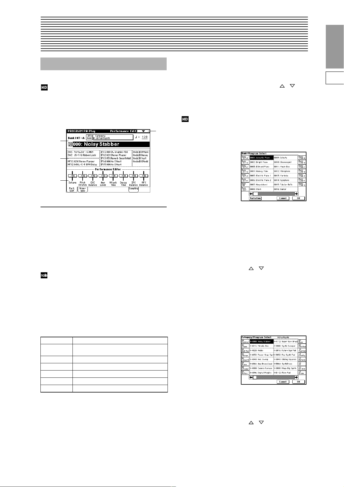
0–1: Perf. Edit (Performance Edit)
0–1
0–1a
0–1b
0–1c
0–1a: Bank, Program Select, Category, 10’s Hold,
Bank (Bank Select)
[INT-A...INT-F, G, g(1)...g(9), g(d), EXB-A...EXB-G]
This is the program bank display.
Use the BANK [INT-A]–[EXB-G] keys to select the bank.
Bank G will advance to the next G (or g) bank each time you
press the [INT-G] key, as shown.
G→g(1)→g(2)→g(3)→g(4)→g(5)→g(6)→g(7)→g(8)→g(9)→
g(d)→G
Bank INT-F can be selected if you have installed the
EXB-MOSS option. When installed, the 128 special
EXB-MOSS programs will be available.
The TRITON STUDIO provides rewritable banks INT-A–
INT-E and EXB-A–EXB-G, each containing 128 programs
(total 1,536). As non-rewritable program areas, it provides
banks G (basic programs for GM2), banks g(1)–g(9) (variation programs), and bank g(d) (drums). ☞A list of the factory-set programs is provided in the separate booklet
“VNL.”
INT-A...INT-D for preloaded programs
INT-E User programs, such as programs that use multi-
samples created in Sampling mode.
INT-F for EXB-MOSS programs
G GM2 basic program
g(1)–g(9) GM2 variation programs*
g(d) GM2 drums program
EXB-A...EXB-G for user programs, and EXB-PCM series programs
* For banks with no variation sounds, the GM basic sounds
will be recalled. (An * will be added at the beginning of
the program name.)
Program Select
(INT -A...INT -F , EXB-A...EXB-G) 0...127,
(G, g(1)...g(9), g(d)) 1...128]
Here you can select a specific program. When this parameter
is selected, you can select programs using the [] []
keys, numeric keys [0]–[9], or [VALUE] dial.
When you press the popup button, the “Bank/Program
Select” menu will appear. This displays programs by bank,
and allows you to select a program.
You can receive MIDI program changes from a connected external MIDI device, or use a foot switch to
select programs. (“Foot SW Assign” Global P2: 2–1a,
“Foot Switch Assign List” ☞p.251)
Bank/Program Select menu:
1 Press the popup button at the left of “Program Select” to
access the Bank/Program Select menu.
2 Press one of the tabs at left or right to select a specific
bank.
If you select the GM bank, the Variation button will be
enabled.
Each time you press the Variation button, the bank will
cycle in the order of G → g(1) → g(2) → ... → g(8) → g(9)
→ G.
3 Select a program from the list. You can press the list to
make a selection, or use the [] [] keys.
4 Press the OK button to execute, or press the Cancel but-
ton to cancel your selection.
Category [00...15]
Selects the program category.
All programs are classified into one of sixteen categories.
You can select the desired category, and then choose programs from that category. Press the popup button, and the
“Category/Program Select” menu will appear.
Category/Program Select menu:
1 Press the (category) popup button above “Program
Select” to access the Category/Program Select menu.
2 Press one of the tabs at left or right to select the desired
category.
3 Select a program from the list. You can press the list to
make a selection, or use the [] [] keys.
4 Press the OK button to execute, or press the Cancel but-
ton to cancel your selection.
The category setting of each program can be specified in the
“Write Program” (0–1A) dialog box.
Program
P0
P1 P2 P3 P4 P5 P7 P8 P9
1
Page 13
10’s Hold
1 Press the [./10’s HOLD] key to display .
The 10’s place of the program number will be held
(fixed).
2 Now you can press any numeric key [0]–[9] to input the
1’s place of the program number with a single keystroke.
3 You can use the [ ] [ ] keys to change the value of the
10’s place.
4 To cancel, press the [./10’s HOLD] key to turn off the
display.
(Tempo) [040...240, EXT]
This sets the tempo of the arpeggiator. The tempo can also
be adjusted by the ARPEGGIATOR [TEMPO] knob.
A display of EXT indicates that the “MIDI Clock” (Global
P1: 1–1a) setting has been set to External MIDI or External
mLAN, and that the arpeggiator will synchronize to MIDI
Clock messages received from an external MIDI device.
0–1b: Program Information
This displays the functions that are assigned to the [SW1]
and [SW2] keys and to the B mode of REALTIME CONTROL knobs [1], [2], [3], [4], and the names of the effects that
are selected for the insertion effects and the master effects.
0–1c: Performance Editor
The Performance Editor lets you edit major program parameters without moving to the Program P1–P9 Edit pages.
This allows you to adjust multiple program parameters
within the currently selected program simultaneously, so
you can make broad adjustments quickly and easily.
You can use the Performance Editor when you wish to
adjust the depth of effects while you are playing, or to make
the initial rough settings to begin the process of creating a
new sound.
If you wish to keep the results of your editing, you must
write (save) the program (☞BG p.56).
Editing done using the Performance Editor will occur
within the range of the corresponding parameter. If
after using the Performance Editor to modify a value,
you move to another page or mode and then return, the
sound will remain in its edited state but the value
shown in the LCD screen by the Performance Editor
will be +00. You may do further editing from this state
if you wish.
Since editing done using the Performance Editor is not
as detailed as conventional editing, the balance
between parameters may be lost. If this occurs, use P1–
P9 Edit page to make fine adjustments.
If the “Enable Exclusive” (Global P1: 1–1b) setting is
checked, MIDI exclusive parameter changes will be
transmitted whenever you operate the Performance
Editor. If these messages are received by a TRITON
STUDIO whose “Enable Exclusive” setting is checked,
the Performance Editor corresponding to that message
will be modified.
Octave [–03...+00...+03]
An adjustment of +01 will raise the pitch one octave.
An adjustment of –01 will lower the pitch one octave.
However, this setting cannot adjust the pitch higher than 4'
(feet) or lower than 32' (feet).
Pitch Stretch [–12...+00...+12]
This simultaneously adjusts the Transpose and Tune of the
oscillator. This lets you produce a variety of tonal changes
and variations without loosing the character of the original
sound.
At the +00 setting, the value of the program parameters will
be unchanged.
An adjustment of +01 will lower the Transpose value by 1,
and simultaneously raise the Tune value by 100.
An adjustment of –01 will raise the Transpose value by 1,
and simultaneously lower the Tune value by 100.
However, it is not possible for the Transpose value to exceed
the range of ±12, nor the Tune value to exceed the range of
±1200.
This Performance Editor function cannot be used with
bank INT-F.
OSC Balance [–10...0...+10]
This adjusts the level balance between oscillators 1 and 2.
At the +00 setting, the value of the program parameters will
be unchanged.
Positive (+) settings will lower the oscillator 2 level.
With an adjustment of +10, the oscillator 2 level will be 0.
The oscillator 1 level will not change.
Negative (–) settings will lower the oscillator 1 level.
With an adjustment of –10, the oscillator 1 level will be 0.
The oscillator 2 level will not change.
For programs whose “Oscillator Mode” (1–1a) setting
is Single, oscillator 2 will not sound. Only the level of
oscillator 1 will change. For a Drums program, this performance editor will have no effect.
Amp Level [–10...0...+10]
This adjusts the amp level.
With an adjustment of +00, the value of the program parameters will be unchanged.
Positive (+) settings will increase the amp level above the
value that was set.
With an adjustment of +10, the amp level will be 127 (maximum).
Negative (–) settings will lower the amp level below the
value that was set.
With an adjustment of –10, the amp level will be 0.
Attack Time [–10...0...+10]
This adjusts the attack times of the filter EG and amp EG.
With an adjustment of +00, the value of the program parameters will be unchanged.
Positive (+) settings will lengthen the attack times beyond
the values that were set.
With an adjustment of +10, the attack times will be 90.
Negative (–) settings will shorten the attack times.
With an adjustment of –10, the attack times will be 0.
When you modify “Attack Time,” the EG Start Level,
Attack Level, Start Level Modulation, and Attack Time
Modulation of the amp EG will also be adjusted simultaneously, to allow the maximum effect to be obtained.
Decay Time [–10...0...+10]
This adjusts the Decay Time and Slope Time of the filter EG
and amp EG.
With an adjustment of +00, the value of the program parameters will be unchanged.
Positive (+) settings will lengthen the Decay Time and Slope
Time beyond the values that were set. With an adjustment of
+10, the times will be 99.
Negative (–) settings will shorten the Decay Time and Slope
Time. With an adjustment of –10, the times will be 0.
2
Page 14
IFX Balance [–10...0...+10]
This adjusts the “Wet/Dry” setting of insert effects 1–5 as a
whole.
With an adjustment of +00, the value of the program parameters will be unchanged.
Positive (+) settings will raise the Wet levels above the program setting, and lower the Dry levels. With an adjustment
of +10, the setting will be “Wet.”
Negative (–) settings will lower the Wet levels below the
program setting, and raise the Dry levels. With an adjustment of –10, the setting will be “Dry.”
MFX Balance [–10...0...+10]
This adjusts the master effect “Return 1” and “Return 2” (9–
1b) settings as a whole.
With an adjustment of +00, the value of the program parameters will be unchanged.
Positive (+) settings will raise the return levels above the
program setting.
With an adjustment of +10, the setting will be 127 (maximum).
Negative (–) settings will lower the return levels below the
program setting.
With an adjustment of –10, the setting will be 0.
Octave Octave of OSC 1/2
Pitch Stretch Transpose and Tune of OSC 1/2
OSC Balance High Multisample, Low Multisample Level of OSC 1/2
Amp Level Amp1 Level, Amp2 Level
Attack Time Amp EG Attack Time, Start Level, Attack Le v el, Le v el
Modulation St, Time Modulation At of Amp 1/2, and
Filter EG Attack Time of Filter 1/2
Decay Time AmpEG Decay Time, Slope Time of Amp 1/2; Filter
EG Decay Time and Slope Time of Filter 1/2
IFX Balance Wet/Dry balance of the IFX1/2/3/4/5 effects
MFX Balance Master Effect Return 1, 2
For the INT-F bank programs that can be used when
the EXB-MOSS option is installed, different program
parameters will be adjusted.
(☞EXB-MOSS owner’s manual)
With the factory settings, the program categories have
been given the names of instruments etc., but you can use
“Program Cat.” (Global P4: 4–1) to modify these category
names. The category selected here can be used to find
this program when selecting a program in Program,
Combination, Sequencer, or Song Play modes.
4 Press “To Program” to specify the writing destination.
You can also use the BANK [INT-A]–[EXB-G] keys to
select a bank.
It is not possible to write to banks G–g(d). If you have
edited a program from banks G–g(d) and wish to write
it, you must write to banks INT-A–INT-E or EXB-A–
EXB-G.
5 To execute the Write Program operation, press the OK
button. To cancel, press the Cancel button.
You can also press the SEQUENCER [REC/WRITE] to
write a program in the same way as “Write Program.”
Press the SEQUENCER [REC/WRITE] key to access the
dialog box, and write the program. In this case, the settings will be written to the currently selected program.
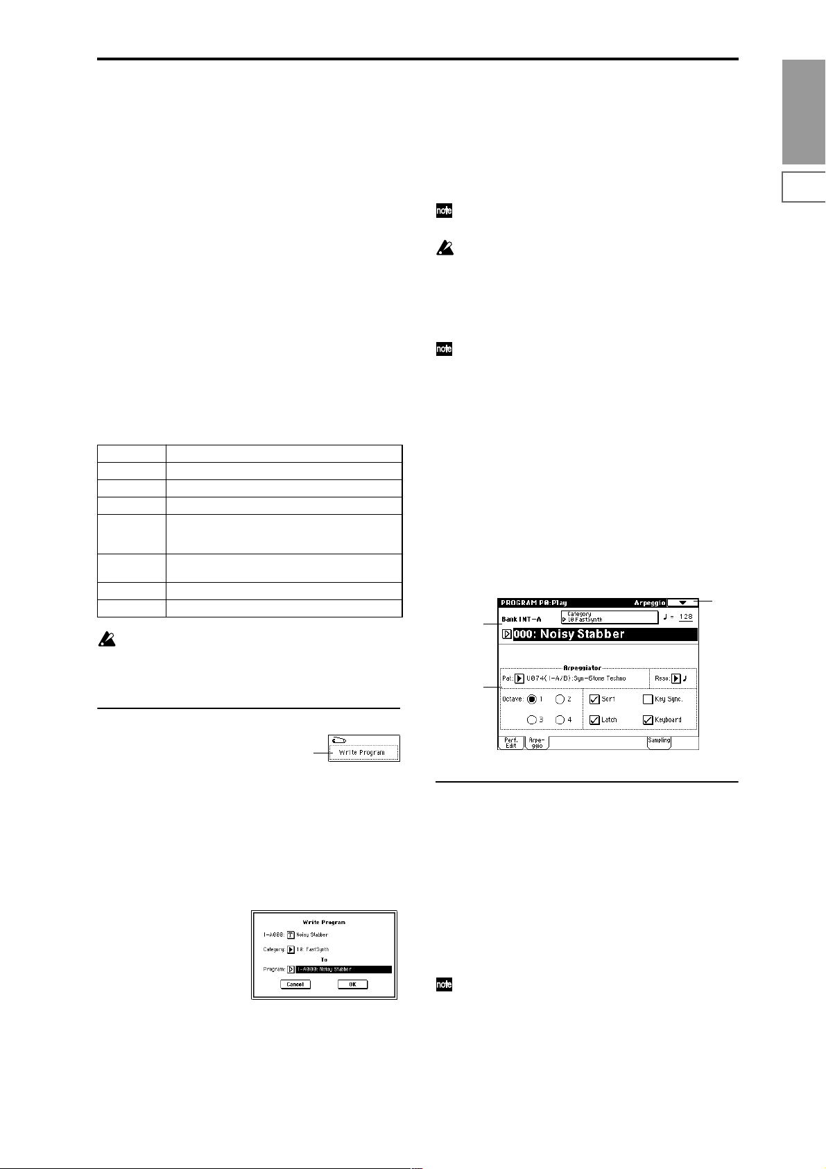
0–2: Arpeggio
Arpeggiator parameters are edited in P7: Edit-Arpeggiator,
but major parameters can be edited here as well. When you
are playing in Program P0: Play, you can edit the arpeggiator in realtime, such as changing the arpeggio pattern etc.
To write (save) the results of your editing, use “Write Program” or “Update Program.” You can also use the [TEMPO],
[GATE], and [VELOCITY] knobs to edit the arpeggio in r ealtime (☞BG p.29, 30).
0–1
0–1a
0–2a
Program
P0
P1 P2 P3 P4 P5 P7 P8 P9
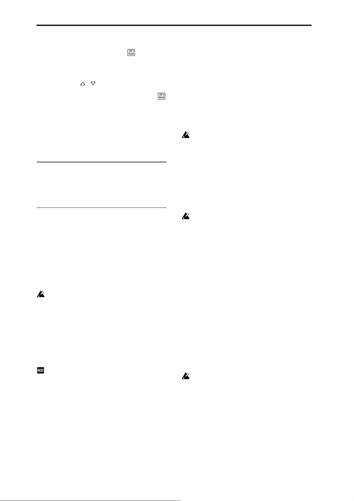
▼ 0–1: Page Menu Command
0–1A
0–1A: Write Program
This command writes the edited program into the internal
memory.
If you wish to save a program, be sure to write it into memory. An edited program cannot be recovered if you do not
write it before turning off the power or selecting another
program.
1 Select “Write Program” to access the dialog box.
2 The upper line shows the bank and program name.
If you wish to modify the program name, press the text
edit button to move to the text edit dialog box, and input
the desired program name.
3 In “Category,” specify the category of the program that
you are writing.
0–2a: Arpeggiator
Pat (Pattern) [P000...P004, U000(I-A/B)...U506(User)]
Octave [1, 2, 3, 4]
Reso (Resolution) [ , , , , , ]
Sort [Off, On]
Latch [Off, On]
Key Sync. [Off, On]
Keyboard [Off, On]
Make settings for the program arpeggiator (☞P7: EditArpeggiator).
These parameters can also be set from P7: Edit-Arpeggiator.
3
Page 15
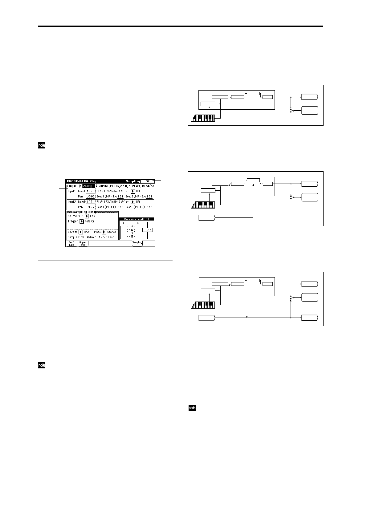
0–3: Sampling
Here you can adjust the settings for the analog/digital audio
signal input (AUDIO INPUT, S/P DIF, EXB-mLAN), and the
settings related to sampling in Program mode.
You can sample either an external audio signal, or a performance played on the TRITON STUDIO.
When sampling in Program mode, you can listen to the performance of the TRITON STUDIO’s arpeggiator etc. while
only sampling the external audio signal via the AUDIO
INPUT jacks or S/P DIF jacks; or you can resample while
you play a program using the TRITON STUDIO’s filters,
effects, and arpeggiator. You can also mix a performance on
the TRITON STUDIO with an external audio signal, and
sample the result. (☞BG p.45)
“Resampling” refers to the process of sampling an
external audio signal, processing this sampled wave
data in the digital domain using effects etc., playing it,
and then once again sampling the resulting performance.
0–3
0–3a
This lets you sample an external audio signal sent to buses 1,
2, 1/2 (specified by “Input” 0–3a), or the sounds sent to the
INDIVIDUAL 1, 2, 1/2 buses from a performance played on
the TRITON STUDIO from its keyboard or via MIDI input.
Normally when you want to sample a performance in Pro-
gram mode, you will select L/R.
PROGRAM
ARPEGGIATOR
Send Return
Insert Effects
Master Effects
= L/R
AUDIO OUTPUT
L/MONO, R
SAMPLING
Master EQOSC / Filter / Amp
Source BUS
Select L/R if you want to mix a Program mode performance
(e.g., drum patterns played by the arpeggiator) with external audio from AUDIO INPUT (or S/P DIF or EXB-mLAN),
and sample them together. In this case, set Input “BUS (IFX/
Indiv .) Select” (0–3a) to L/R so that the external audio signal
will be sent to the L/R bus.
PROGRAM
ARPEGGIATOR
Send Return
Insert Effects Master EQOSC / Filter / Amp
Master Effects
Source BUS
= L/R
AUDIO OUTPUT
L/MONO, R
SAMPLING
0–3b
0–3c
0–3a: Input (COMBI, PROG, SEQ, S.PLAY, DISK)
Input [Analog, S/P DIF, mLAN]
Input1:
Input2:
Level [0...127]
Pan [L000...C064...R127]
BUS(IFX/Indiv.) Select
[L/R, IFX1…5, 1, 2, 3, 4, 1/2, 3/4, Off]
Send1(MFX1), Send2(MFX2) [000...127]
Here you can specify the input source analog/digital audio
device, and set the input level, pan, bus, and master effect
sends.
These Input settings are valid in Combination, Program,
Sequencer, Song Play, and Disk modes. (☞Global P0: 0–
3a)
0–3b: Sampling Setup
Source BUS [L/R, Indiv.1/2]
Selects the source that you want to sample. The sound being
sent to the bus selected here will be sampled.
L/R: The sound sent to the L/R bus will be sampled.
This lets you sample an external audio signal sent to the L/R
bus (specified by “Input” 0–3a), or the sounds sent to the L/
R bus from a performance played on the TRITON STUDIO
from its keyboard or via MIDI input.
Indiv. 1/2: The sound sent to the INDIVIDUAL 1, 2, 1/2
buses will be sampled.
AUDIO INPUT 1,2
(IFX1-5)
"BUS(IFX/Indiv.) Select"
= L/R
Select Indiv.1/2 if you want to monitor your playing in Pro-
gram mode while sampling only an external audio signal
from AUDIO INPUT (or S/P DIF or EXB-mLAN). In this
case, set Input “BUS (IFX/Indiv.) Select” (0–3a) to 1, 2, or 1/2
so that the external audio signal will be sent to the INDIVIDUAL 1, 2, or 1/2 buses.
PROGRAM
ARPEGGIATOR
AUDIO INPUT 1,2
Insert Effects Master EQOSC / Filter / Amp
(IFX1-5)
Send Return
Master Effects
"BUS(IFX/Indiv.) Select"
= 1, 2, 1/2
Source BUS
= Indiv.1/2
AUDIO OUTPUT
L/MONO, R
SAMPLING
AUDIO OUTPUT
INDIV.1, 2
Trigger [Sampling START SW, Note On]
This specifies how sampling will begin.
Sampling START SW: The TRITON STUDIO will enter
sampling-standby mode when you press the SAMPLING
[REC] key. Sampling will begin when you press the SAMPLING [START/STOP] key.
Note On: The TRITON STUDIO will enter samplingstandby mode when you press the SAMPLING [REC] key
and then press the SAMPLING [START/STOP] key. Sampling will begin when you play the keyboard.
Sampling will also begin if a MIDI note-on is received.
To stop sampling in either case, press the SAMPLING
[START/STOP] key once again. Alternatively, sampling will
stop automatically when the specified “Sample Time” is
reached.
For details on the procedure, refer to p.97.
4
Page 16
Metronome Precount [Off, 4, 8, 3, 6]
This specifies whether the metronome will sound a countdown when you begin sampling with the “Trigger” setting
Sampling START SW.
This can be set only if “Trigger” is set to Sampling START
SW.
Off: When you press the SAMPLING [START/STOP] key
from recording-standby mode, sampling will begin immediately.
4, 8, 3, 6: When you press the SAMPLING [START/STOP]
key from recording-standby mode, the specified number of
beats will be counted at the “ (T empo)” (0–1a) tempo befor e
sampling will begin. If this is set to 4, sampling will begin on
the count of 0 after a count-down of 4–3–2–1–0.
The output destination and level of the metronome
sound are specified by the page menu command “Met-
ronome Setup” (0–3A). If “BUS (Output) Select” is set
to L/R, the metronome will stop sounding the instant
sampling begins.
Save to [RAM, DISK]
Specifies the destination to which the data will be written
during sampling.
RAM: Sample into sample memory (RAM).
If you sample into sample memory (RAM), you will be able
to immediately hear the sample in Program mode or Sampling mode.
Settings for the writing destination RAM Bank and Sample
No., and settings for automatically converting the sample to
a program, are made by the page menu command “Select
Bank & Smpl No.” (0–3C).
If the sample is written into RAM, it will be lost when
the power is turned off, so you will need to save the
sample if you want to keep it.
DISK: Samples to the internal hard drive or to an external
hard drive connected to the SCSI connector.
A WAVE file will be created when you sample.
To listen to the sampled result, you can either load the sample into sample memory (RAM) in Disk mode, or use the
page menu command “Select Directory” (0–3D) etc. to select
the file and then press the SAMPLING [START/STOP] key.
Use the page menu command “Select Directory” to specify
the writing-destination drive, directory, and filename.
A single sample (WAVE file) loaded from hard disk into
sample memory (RAM) may not exceed 16 MB for
mono or 32 MB for stereo (however, sample memory
must be expanded to 32 MB or more).
It is not possible to sample directly to CD-R/RW. Also,
we do not recommend sampling to a removable disk.
Mode (Sample Mode) [L-Mono, R-Mono, Stereo]
Selects the channel(s) that will be sampled, to specify
whether the sample created will be mono or stereo.
The sound being sent to the internal L and/or R bus or the
internal Indiv.1 and/or 2 bus selected by the “Source BUS”
(0–3b) setting will be sampled.
L-Mono: The internal L channel or internal Indiv.1 channel
(as specified by “Source BUS”) will be sampled in mono.
R-Mono: The internal R channel or internal Indiv.2 channel
(as specified by “Source BUS”) will be sampled in mono.
Stereo: The internal L and R channels or internal Indiv.1
and 2 channels (as specified by “Source BUS”) will be sampled in stereo. This will create a stereo sample. (☞Sampling
P0: 0–1c)
Sample Time [min sec]
Specifies the length of time that you want to sample. This
can be set in units of minutes and 0.001 second.
This parameter indicates amount of remaining memory in
the selected memory bank (the available sampling time). If
you sample in this state ([REC]→[START]→[STOP]), this
display will change automatically to indicate the remaining
time.
If you have enough free space in sample memory (RAM), it
is a good idea to set “Sample Time” generously, and then
after recording the sample, use the page menu command
“Truncate” (Sampling P1: 1–1A, P2: 2–1A) to delete the
unneeded portion, making the sample as compact as possible. You can also stop recording by pressing the SAMPLING
[START/STOP] key manually after the desired portion has
been sampled. (Sampling methods ☞BG p.45)
If the writing-destination (“Save to”) is RAM, the maximum
value will be calculated from the amount remaining in the
selected Bank. (☞Sampling P0: 0–1c “Bank (RAM Bank)”)
If the writing-destination (“Save to”) is DISK, the maximum value will be calculated from the remaining capacity
of the disk specified by “Select Directory.” A maximum of 80
minutes can be sampled in one sample file for either mono
or stereo (monaural: approximately 440 MB, stereo: approximately 879 MB).
If the writing-destination (“Save to”) is RAM, leaving
“Auto Optimize RAM” (Global P0: 0–3b) unchecked
will allow wasted space to increase, decreasing the
available sample memory (RAM). In this case, execute
the page menu command “Optimize RAM” to eliminate the wasted space.
The remaining amount of RAM can be checked in Sampling mode P0: Recording, Memory Status.
The various Sampling Setup settings apply to the entire
Program mode, not just to an individual program.
0–3c: Recording Level [dB]
ADC OVERLOAD !!
The “ADC OVERLOAD !!” indication will appear if the signal level from AUDIO INPUT 1, 2 is too high. In this case,
adjust the [LEVEL] knob or the output level of the external
audio source. (☞Sampling P0: 0–1d “Recording Level [dB]”)
Recording Level [–inf, –72.0...0.0...+18.0 dB]
Adjusts the signal level at the final stage of sampling
(☞Sampling P0: 0–1d). Sample at the highest level that does
not make the level meter indicate CLIP.
Adjusting the “Recording Level” will not change the
sound that is output, but will affect the data that is
being sampled. This means that the sampled sound
may be distorted even if the sound you hear is not distorted.
This setting defaults to –12 dB when you turn on the power.
At a setting of –12 dB, CLIP will not appear even if you play
the program at its maximum level.
The “+12 dB” (Sampling P2: 2–1c) setting is applied to
samples that you recorded into sample memory (RAM)
when “Save to” (0–3b) is set to RAM. When “+12 dB” is
on, the playback level will increase by approximately
+12 dB.
If you check the “Auto +12 dB On” check box in the
page menu command “Select Bank & Smpl No.” (0–
3C), the “+12 dB” setting will automatically be turned
on during sampling.
Program
P0
P1 P2 P3 P4 P5 P7 P8 P9
5
Page 17

The “Auto +12 dB On” setting will not affect samples
that you recorded to the internal hard disk etc. when
“Save to” (0–3b) is set to DISK. You can use “WAVE
File Play Level” (Global P0: 0-2a) to set the playback
level.
▼ 0–3: Page Menu Command
0–1A
0–3A
0–3B
0–3C
0–1A
0–3A
0–3B
0–3D
0–3A: Metronome Setup
Specifies the output destination and volume of the metronome that is sounded when you use “Trigger” Sampling
START SW to begin sampling.
1 Select “Metronome Setup” to access the dialog box.
2 In “BUS (Output) Select,” specify the output destination
of the metronome sound. If you select L/R, the metronome will stop as soon as sampling begins.
3 Set “Level” to specify the volume of the metronome.
4 Press the OK button to apply the settings you made, or
press the Cancel button to return to the state prior to
accessing this dialog box.
The metronome is valid only if “Trigger” is set to Sam-
pling START SW.
0–3B: Optimize RAM
This command optimizes the sample memory (RAM).
When you execute this command, unused memory areas
will be reorganized, allowing the full amount of remaining
to be used.
If you run out of memory, try executing “Optimize RAM.”
The remaining amount of RAM can be checked in Sampling
mode P0: Recording, Memory Status.
1 Select “Optimize RAM” to access the dialog box.
2 Press the OK button to execute the command, or press
the Cancel button to cancel without executing.
If “Auto Optimize RAM” (Global P0: 0–3b) is checked,
RAM will be optimized automatically.
0–3C: Select Bank & Smpl No.
Specifies the RAM bank and sample number into which the
sampled data will be written. You can also specify whether
the sample will automatically be converted to a program
after sampling. “Select Bank & Smpl No.” can be selected if
you have selected RAM as the “Save to” destination.
1 Select the “Select Bank & Smpl No.” to access the dialog
box.
2 In “Bank,” specify the sample memory (RAM) bank to
which the sampled data will be written.
3 In “Sample No.,” specify the writing-destination sample
number. By default, this will be the lowest-numbered
vacant sample number. If you select “----:----No Assign----”
or a sample number that already contains data, the data
will automatically be sampled into the lowest vacant
sample number. If you are sampling in stereo, specify
“Sample No.(L)” and “Sample No.(R).”
4 Set “Auto +12 dB On.”
On (checked): “+12 dB” (Sampling P2: 2–1c) will auto-
matically be turned on for samples you record. Samples
for which “+12 dB” is on will play back approximately
+12 dB louder than if this setting were off.
When you resample a performance in Program, Combination, or Sequencer modes, you should normally set
“Recording Level” to about –12.0 (dB) so that the record-
ing level will be as high as possible without clipping.
When you resample, the sound will be recorded at the
optimum level for sampled data, but the playback level
at playback will not be as loud as it was during the resampling process (if “+12 dB” (Sampling P2: 2–1c) is off). In
such cases, you can check the “Auto +12 dB On” check
box when you resample, so that “+12 dB” (Sampling P2:
2–1c) will automatically be on, making the sample play
back at the same level as when it was resampled.
In these modes, the power-on defaults are “Recording
Level” set to –12.0 (dB) and “Auto +12 dB On” turned on.
If you resample a performance in one of these modes
with these settings, the sample will play back at the same
level at which it was resampled.
If you want to monitor your performance in Program,
Combination, or Sequencer mode while sampling only
the external audio signal from AUDIO INPUT etc. (the
“Source BUS” Indiv.1/2 setting: 0–3b), we recommend
that you set “Recording Level” to about +0.0 (dB) and
turn off “Auto +12 dB On” when you resample.
The “Auto +12 dB On” setting is made independently
for Program, Combination, Sequencer, and Sampling
modes.
5 “Convert to” specifies whether the sample will automati-
cally be converted into a program as soon as it has been
sampled. This is convenient when you want to hear the
sound immediately after sampling.
If you check the “Program” check box, the sample will
automatically be converted into a program.
At the right, set “Program” and “MS” to specify the program number and multisample number for the converted program.
Set “Orig. Key” (Sampling P0: 0–1b) to specify the location of the original key. The multisample will create an
“Index” (Sampling P0: 0–1a) with this key as the “Top
Key” (Sampling P0: 0–1b). The “Orig. Key” will incre-
ment by one after sampling, and the next higher note will
be assigned the next time you sample.
6 Press the OK button to apply the settings you made, or
press the Cancel button to return to the state prior to
accessing this dialog box.
6
Page 18
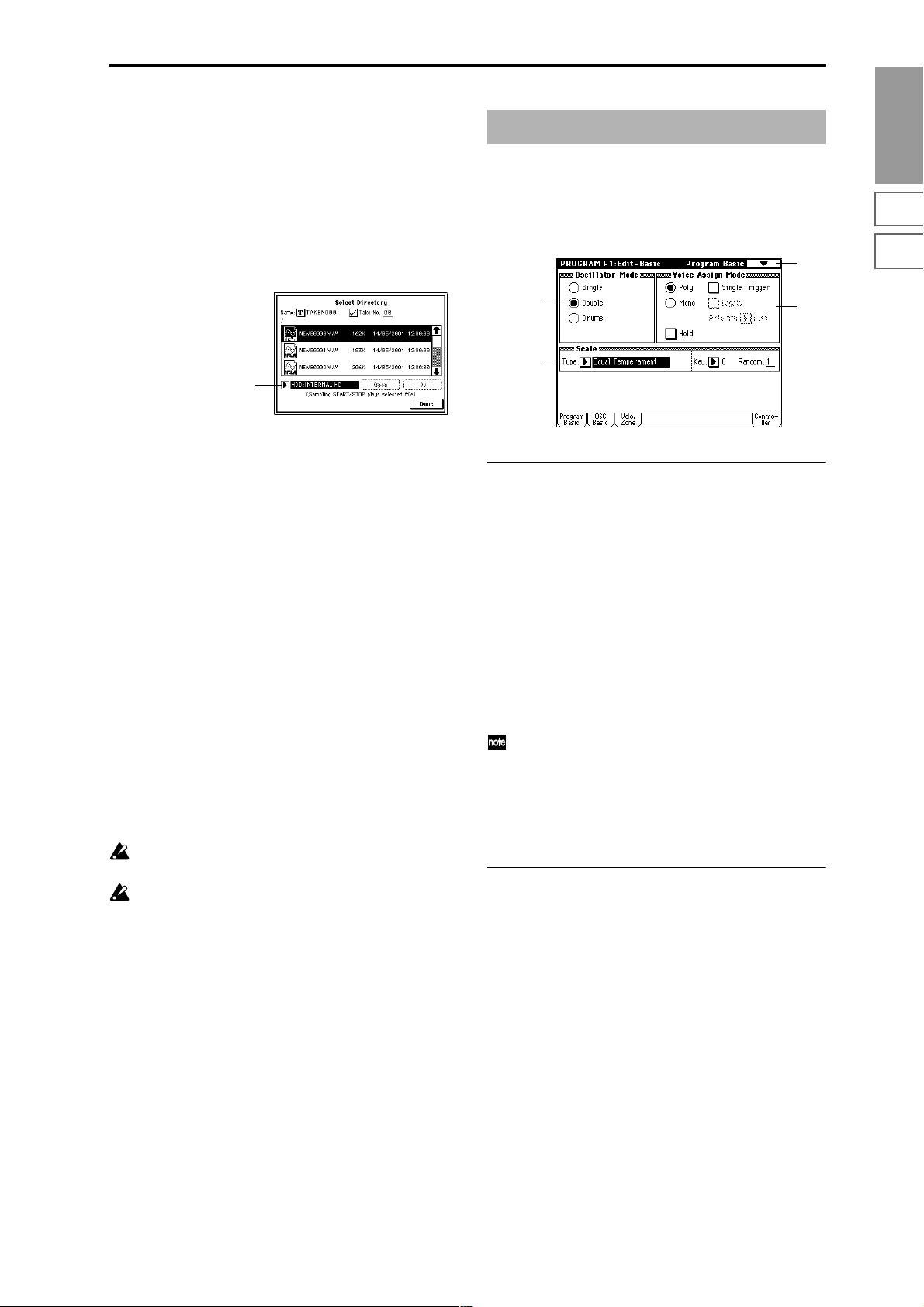
0–3D: Select Directory
This lets you select the disk (internal hard disk, etc.) and
directory on which the WAVE file created by sampling will
be saved, and specify a filename.
Y ou will also choose this “Select Dir ectory” command when
you want to listen to a WAVE file that was saved on disk.
“Select Directory” can be selected when “Save to” is set to
DISK.
Specifying the save destination for a WAVE file
1 Select the “Select Directory” to access the dialog box.
Program P1: Edit–Basic
Here you can make basic settings for the program, such as
oscillator mode and scale type.
1–1: Program Basic
1–1
Program
P0
P1 P2 P3 P4 P5 P7 P8 P9
Drive select
2 Use the popup button located at the left of “Drive select”
to select the writing-destination drive for sampling.
3 Use the Open button and Up button to move to the
desired directory.
4 In “Name,” specify a name for the WAVE file that will be
written during sampling.
If you check “Take No.,” the file will be saved with a
two-digit “Take No.” added to the end of the filename.
This number will automatically increment each time you
sample. This is convenient when you are sampling
repeatedly, since each sample will be saved with its own
filename.
If “Take No.” is not checked, you can input up to eight
characters in “Name.” If “Take No.” is checked, you can
input up to six characters.
5 Press the Done button to complete the settings.
Playing back a WAVE file
1 Select the “Select Directory” to access the dialog box.
2 Use “Drive Select” and the Open and Up buttons to
select the drive and directory, and select the WAVE file
(44.1 kHz or 48 kHz) that you want to play.
3 Press the SAMPLING [START/STOP] key.
The selected WAVE file will be played.
4 Press the SAMPLING [START/STOP] key once again to
stop playback.
If the W AVE file is mono, the same sound will be output
to L/R.
While the WAVE file is playing back, sound cannot be
produced by playing the keyboard or receiving note
data at MIDI IN. Also, the arpeggiator will stop.
1–1a
1–1c
1–1b
1–1a: Oscillator Mode
Oscillator Mode [Single, Double, Drums]
Specifies the Program’s oscillator assignment; whether it
will use one or two oscillators, or a drum kit.
Single: The program will use one oscillator (Oscillator 1,
Filter 1, Amplifier 1). In this case the program will normally
have a maximum of 60-note polyphony.
Double: The program will use two oscillators (Oscillator 1/
2, Filter 1/2, Amplifier 1/2). In this case the program will
normally have a maximum of 30-note polyphony.
Drums: The program will use one oscillator (as when Single
is selected), but Oscillator 1 will be assigned a drum kit
instead of a multisample. In this case the program will normally have a maximum of 60-note polyphony.
If a program draws one multisample from the ROM
bank, and a second from either the Piano bank or one of
the installed EXB boards, then in this case, a Single program can have a maximum of 120-note polyphony, a
Double program a maximum of 60-note polyphony,
and a Drums program a maximum of 120-note polyph-
ony. (☞BG p.15)
1–1b: Voice Assign Mode
Mode (Voice Assign Mode) [Poly, Mono]
Poly: The program will play polyphonically, allowing you
play chords.
Mono: The program will play monophonically, producing
only one note at a time.
Single Trigger [Off, On]
This is available when the “Mode (Voice Assign Mode)”
setting is set to Poly.
On (checked): When the same note is played repeatedly, the
previous note will be silenced before the next note is
sounded, so that the notes do not overlap.
Legato [Off, On]
This is available when the “Mode (Voice Assign Mode)”
setting is set to Mono.
On (checked): Legato is on. When multiple note-on’s occur,
the first note-on will retrigger the sound, and the second and
subsequent note-on’s will not retrigger.
7
Page 19
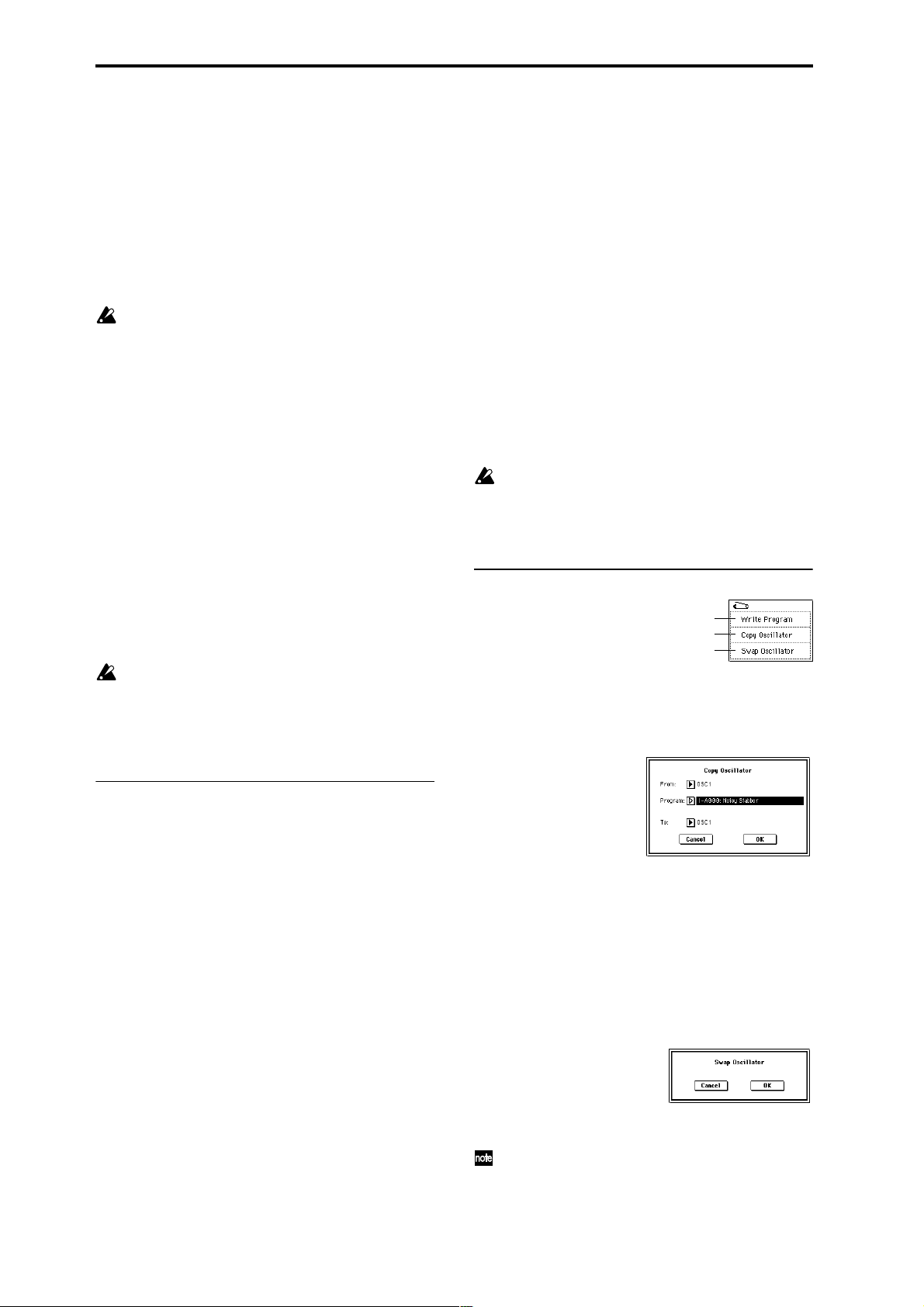
When legato is on, multiple note-on message will not retrigger the voice. If one note is already on and another note is
turned on, the oscillator sound, envelope, and LFO will not
be reset, and only the pitch of the oscillator will be updated.
This setting is effective for wind instrument sounds and
analog synth-type sounds.
Off (unchecked): Legato is off. Notes will always be retriggered when note-on occurs.
When legato is off, multiple note-on’s will retrigger the
voice at each note-on. The oscillator sound, envelope, and
LFO will be reset (and retriggered) according to the settings
of the program.
If “Legato” is checked, certain multisamples or keyboard locations may produce an incorrect pitch.
Priority [Low, High, Last]
This parameter is valid when “Mode (Voice Assign Mode)”
is set to Mono.
It specifies which note will be given priority to play when
two or more notes are played simultaneously.
Low: Lowest note will take priority.
High: Highest note will take priority.
Last: Last note will take priority.
Hold [On, Off]
On (checked): Hold is On. Even when you take your finger
off of the key, the note will continue sounding as if it continued to be held. Unless the Amp1 EG, Amp2 EG (4–3a, 4–6)
“Sustain (Sustain Level)” is set to 0, the sound will continue
playing.
This is ideal for playing drum programs, and when you set
“Oscillator Mode” (1–1a) to Drums, you should turn On.
Off (unchecked): Hold is Off. Except for drum programs,
you should normally set Off.
If you turn “Hold” On for a drum program, keys of the
selected drum kit whose “Enable Note Off Receive”
parameter (Global P5: 5–2a) is unchecked will be set to
Hold On. Keys that are checked will be set to Hold Off.
If you select Hold Off, the keys will be set to Hold Off
regardless of their “Enable Note Off Receive” setting.
octave consists of seven notes.
When “Key” is set to C, use the white keys. (The black keys
will sound the equal tempered pitches.)
Stretch: This tuning is used for acoustic pianos.
User All Notes Scale: This is the full-range scale (C–1 – G9)
that was specified in “User All Notes Scale” (Global P3: 3–
1b).
User Octave Scale 00–15: These are the single-octave scales
that were specified in “User Octave Scale” (Global P3: 3–1a).
Key (Scale Key) [C…B]
Selects the tonic note of the specified scale.
This setting is not valid for Equal Temperament, Stretch,
and User All Notes Scale.
Random [0…7]
As this value is increased, a greater variance will be applied
to the pitch when each note is sounded. Normally you will
set this to 0. This parameter is used when simulating instruments that have natural instability in pitch, such as tapemechanism organs or acoustic instruments.
If a scale other than Equal T emperament is selected, the
combination of the selected scale and the “Key” setting
may skew the tuning of the base key (for example
A=440 Hz). If this occurs, use “Master Tune” (Global
P0: 0–1a) to correct the pitch.
▼ 1–1: Page Menu Command
0–1A
1–1A
1–1B
1–1A: Copy Oscillator
This command is used to copy the settings from one oscillator to another.
1 Select “Copy Oscillator” to access the dialog box.
1–1c: Scale
Type [Equal Temperament…User Octave Scale15]
Selects the basic scale for the internal tone generator.
Equal Temperament: This is the most widely used scale,
where each semitone step is spaced at equal pitch intervals.
Pure Major: In this temperament, major chords of the
selected tonic will be perfectly in tune.
Pure Minor: In this temperament, minor chords of the
selected tonic will be perfectly in tune.
Arabic: This scale includes the quarter-tone scale used in
Arabic music.
Pythagoras: This scale is based on ancient Greek musical
theory, and is especially effective for playing melodies.
Werkmeister (Werkmeister III): This is an equal tempered
scale that was used since the later Baroque period.
Kirnberger (Kirnberger III): This scale was created in the
18th century, and is used mainly to tune harpsichords.
Slendro: This is an Indonesian gamelan scale in which an
octave consists of five notes.
When “Key” is set to C, use the C, D, F, G and A notes.
(Other keys will sound equal-tempered pitches.)
Pelog: This is an Indonesian gamelan scale in which an
8
2 In “From” specify the oscillator to copy, and in “Pro-
gram” specify the bank and number of the copy source
program. You can use the Bank [INT-A]–[EXB-G] keys to
select the bank.
3 In “To,” specify the copy destination oscillator.
4 To execute the Copy Oscillator command, press the OK
button. To cancel, press the Cancel button.
1–1B: Swap Oscillator
This command exchanges the settings of oscillators 1 and 2.
1 Select “Swap Oscillator” to access the dialog box.
2 To execute the Swap Oscillator command, press the OK
button. To cancel, press the Cancel button.
This can be selected only if “Oscillator Mode” (1–1a) is
Double.
Page 20
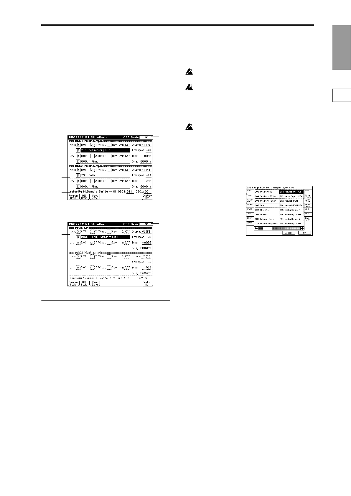
1–2: OSC Basic
The multisample(s) (waveform) or drum kit on which the
program will be based can be selected here for oscillator 1
and/or oscillator 2.
Internal ROM contains 429 (425: ROM + 4: Piano) different
multisamples (preset multisamples) and 153 drum kits. By
selecting a RAM multisample, you can use a multisample
that you created in Sampling mode or that you loaded in
Disk mode. If any of the EXB-PCM series options have been
installed, you will be able to select from among their multisamples as well. The following illustration shows a LCD
screen where “Oscillator Mode” (1–1a) has been set to Dou-
ble. If this is set to Single, the OSC2 Multisample (1–2b) will
not appear and cannot be set.
1–2
1–2a
1–2b
1–2c
The following illustration shows the display when “Oscilla-
tor Mode” (1–1a) has been set to Drums.
EXB*: Multisamples from EXB-PCM series option boards
can be selected. “*” will indicate the type of installed option.
The multisample number for “High Multisample” will
depend on which EXB-PCM options have been installed.
The EXB* display will differ depending on the type of
option board.
If a program that uses a multisample from an EXB-PCM
series board is selected, but the corresponding EXBPCM (expansion board) is not installed, the “High MS
Bank” field will indicate ROM. In this case, the program will not sound. By re-selecting the multisample
bank, you can make the program sound.
Each multisample has an upper limit, and may not produce sound when played above that limit.
When you press the “High Multisample” popup button, a
multisample list will appear, allowing you to select a multisample from the list.
If ROM is selected as the “High MS Bank,” you can select a
multisample from a tabbed list organized by type of instrument.
Category/ROM Multisample Select menu:
Program
P0
P1 P2 P3 P4 P5 P7 P8 P9
1–2
1–2d
1–2a: OSC1 Multisample
Here you can select a multisample.
Y ou can select differ ent multisamples for High and Low, and
use velocity to switch between the two multisamples. Start
Offset, Reverse, and Level can be adjusted independently
for the High and Low multisamples.
High:
High MS Bank [ROM, RAM, Piano, EXB*...]
High Multisample
[000...424, 000...999, 000...003, 000...]
Specifies the bank and multisample number of the High
multisample. The multisample you select here will sounded
by velocities greater than the value of the “Velocity M.Sam-
ple SW Lo→Hi” (1–2c) parameter “OSC1.” If you do not
wish to use velocity switching, set “OSC1” to a value of 001,
and select only the High multisample.
ROM: Selects a preset multisample. Use “High Multisam-
ple” to select from 000–424.
RAM: Selects a multisample that you created in Sampling
mode or that you loaded in Disk mode. Use “High Multi-
sample” to select from 000–999.
Piano: You can select preset multisamples such as stereo
piano. Choose from 000–003 for the “High Multisample.”
S.Offset (High Start Offset) [Off, On]
This specifies the point at which the multisample will begin
sounding. For some multisamples this parameter will have
no effect.
On (checked): The sound will start from the start offset location that is pre-determined for each multisample.
However when a RAM bank is selected, this will depend on
the selected multisample. If you select a multisample that
includes one of the following types of sample, checking this
item will cause playback to start from the Loop Start Address.
• A sample that was recorded (sampled) in Sampling
mode
• A sample whose Loop Start Address was edited in
Sampling mode after the sample was loaded in Disk
mode
• A sample whose Loop Start Address was specified
automatically when it was loaded as an AKAI, AIFF, or
WAVE file in Disk mode
Off (unchecked): The sound will start from the beginning of
the multisample waveform.
Rev (High Reverse) [Off, On]
The multisample will be played in reverse. In the case of
ROM or optional (EXB-PCM series) multisamples that were
originally specified to loop, or in the case of multisamples
that were set to loop in Sampling mode, the multisample
will be played back in “one-shot” reverse mode. If the multisample was originally set to reverse, it will playback without change.
On (checked): The multisample will playback in reverse.
Off (unchecked): The multisample will playback normally.
9
Page 21
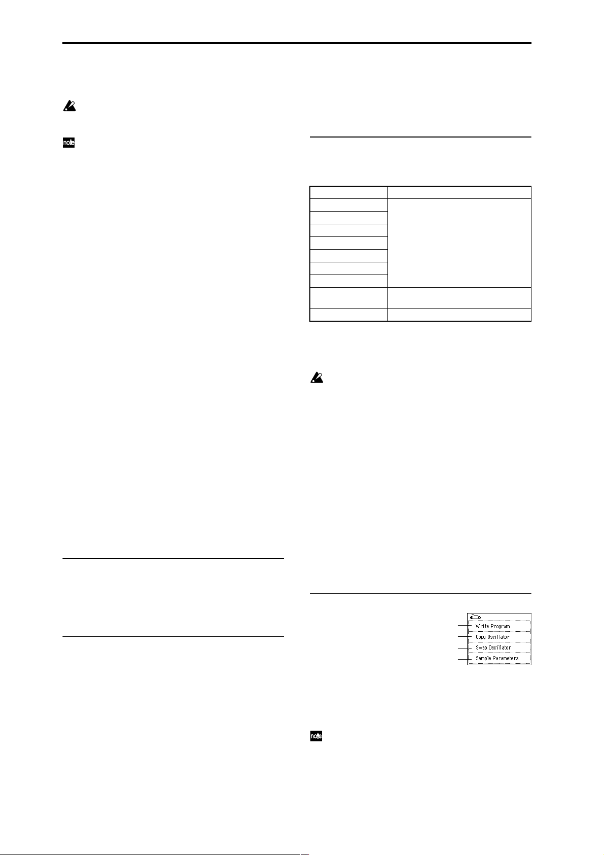
Lvl (High Level) [000…127]
Specifies the level of the multisample.
Depending on the multisample, high settings of this
parameter may cause the sound to distort when a chord
is played. If this occurs, lower the level.
The playback level for a RAM multisample is also
affected by the “+12 dB” (Sampling P2: 2–1c) setting for
each sample. If the “+12 dB” setting is on, the playback
will be approximately +12 dB louder. (☞0–3C)
Low:
Here you can assign the Low multisample for OSC1.
The multisample you select here will sounded by velocities
less than the value of the “Velocity M.Sample SW Lo→Hi”
(1–2c) parameter “OSC1.”
Low MS Bank [ROM, RAM, Piano, EXB*...]
Low Multisample
[000...424, 000...999, 000...003, 000...]
S.Offset (Low Start Offset) [Off, On]
Rev (Low Reverse) [Off, On]
Lvl (Low Level) [000…127]
☞ For details on the “Low” parameters, refer to the explana-
tions for the corresponding “High” parameters.
Octave [–2[32’], –1[16’], +0[8’], +1[4’]]
Adjusts the pitch in octave units. The normal octave of the
multisample is pitched at 8' (feet).
Transpose [–12…+12]
Adjusts the pitch in semitone steps over a range of ±1
octave.
Tune [–1200…+1200]
Adjusts the pitch of the sample in one-cent steps (a semitone
is 100 cents) over a range of ±1 octave.
Delay [0ms…5000ms, KeyOff]
Specifies a delay time from note-on until the note will sound.
With a setting of KeyOff, the sound will begin when note-of f
occurs. This is used to create sounds such as the “click” that is
heard when a harpsichord note is released. In this case, set the
Amp1 EG, Amp2 EG (4–3a, 4–6) “Sustain” parameter to 0.
1–2b: OSC2 Multisample
This will appear when “Oscillator Mode” (1–1a) is set to
Double.
For details on the settings and function of the parameter,
refer to “1–2a: OSC1 Multisample.”
1–2c: Velocity M.Sample SW Lo → Hi
(Velocity Multisample Switch Low → High)
OSC1 (OSC1 Velocity Switch) [1…127]
The High and Low multisamples selected for oscillator 1 in
“OSC 1 Multisample” (1–2a) will be switched at the velocity value that you specify here.
Notes played with a velocity stronger than this value will be
sounded by the High multisample.
OSC2 (OSC2 Velocity Switch) [1…127]
This will appear when “Oscillator Mode” (1–1a) is set to
Double.
The High and Low multisamples selected for oscillator 2 in
“OSC 2 Multisample” (1–2b) will be switched at the velocity value that you specify here.
Notes played with a velocity stronger than this value will be
sounded by the High multisample.
1–2d: Drum Kit
Drum Kit [000(I-A/B)...143(User), 144(GM)...152(GM)]
Selects a drum kit.
000(I-A/B)–015(I-A/B) Preloaded drum kits
16(E-A)–31(E-A)
32(E-B)–47(E-B)
48(E-C)–63(E-C)
64(E-D)–79(E-D)
80(E-E)–95(E-E)
96(E-F)–111(E-F)
112(E-G)–127(E-G)
128(User)–143(User) User drum kits
144(GM)–152(GM) ROM preset drum kits compatible with GM2
User drum kits
EXB-PCM series drum kits
(some preloaded drum kits)
Octave [–2[32’], –1[16’], +0[8’], +1[4’]]
Adjusts the pitch in octave units. When using a drum kit, set
the Octave to 8'.
When editing a drum program, you must set this
parameter to 8'. With other settings, the sounds of the
drum kit will be assigned to the wrong notes of the keyboard.
Transpose [–12…+12]
This adjusts the location of the instruments in the selected
drum kit. Unless you need to change this, leave it at 0.
Tune [–1200…+1200]
This adjusts the pitch in one-cent units.
The pitch of each drum kit can be adjusted in Global P5:
Drum kit.
Delay (Delay Time) [0ms…5000ms, KeyOff]
This specifies a delay time from note-on until the sound will
begin.
With a setting of KeyOff, the sound will begin when noteoff occurs. In this case, set the Amp EG (4–3a) parameter
“Sustain” to 0.
▼ 1–2: Page Menu Command
0–1A
1–1A
1–1B
1–2A
1–2A: Sample Parameters
Specifies the sample for each index of a RAM multisample.
You can adjust the playback level, cutoff, resonance, pitch,
attack, and decay.
This can be selected if “Oscillator Mode” (1–1a) is Sin-
gle or Double, and RAM is selected as the “High MS
Bank” or “Low MS Bank” for OSC1 Multisample or
OSC2 Multisample and “High Multisample” or “Low
Multisample” are selected.
10
Page 22
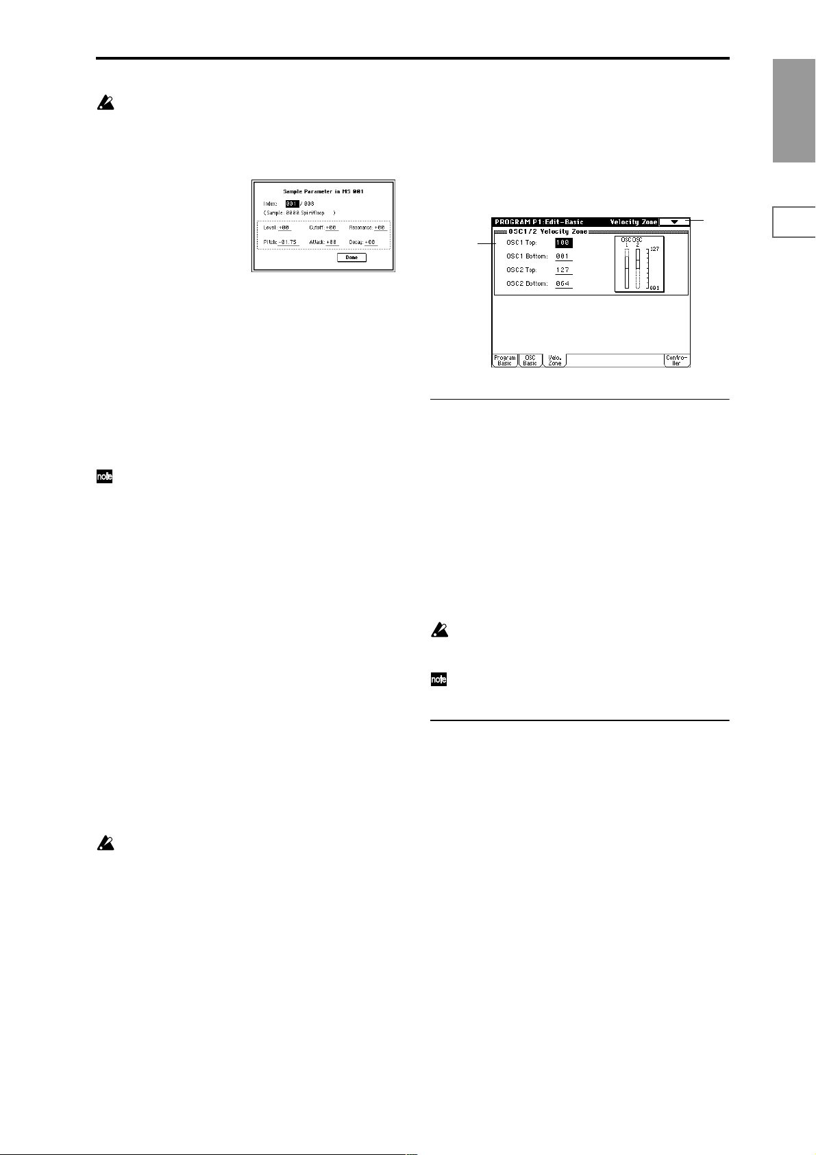
These settings are made for the selected multisample. If
another oscillator or program uses that multisample,
that oscillator or program will also be affected by the
changes you make here.
1 Select “Sample Parameters” to access the dialog box.
1–3: Velo. Zone (Velocity Zone)
Here you can specify the velocity range at which each oscillator will sound.
The “Velocity M.Sample” SW Lo→Hi” (1–2c) setting in conjunction with these “OSC 1/2 Velocity Zone” settings will
determine the velocity ranges in which the High and Low
multisample or drum kit will sound.
Program
P0
2 Index: Specify the index for which you wish to make set-
tings. The number following “/” is the total number of
indexes in the selected multisample.
Sample: indicates the sample number and name for the
index.
3 For each index, you can make the following settings.
Level: Adjust the volume. Relative to the settings of
“Lvl” (1–2a) and “Amp Level” (4–1a, 4–4), negative (–)
values will decrease the levels, and positive (+) values
will increase the levels. A setting of +99 will double the
volume. This parameter is linked to the “Level” (Sampling P3: 3–1b). The value that was specified in Sampling
mode will be displayed here.
The volume is also affected by the “+12 dB” (Sampling
P2: 2–1c) setting. If the “+12 dB” setting is on, the playback will be approximately +12 dB louder.
Cutoff: Adjusts the filter cutoff. This adjustment will be
added to the value specified for “(Filter A) Frequency”
(3–1b, 3–5) of Filter 1 and 2.
Resonance: Adjusts the resonance level of the filter. This
adjustment will be added to the value specified for “(Filter A) Resonance” (3–1b, 3–5) of Filter 1 and 2.
Pitch: Adjusts the playback pitch in one-cent steps. A setting of +12.00 raises the pitch one octave, and a setting of
–12.00 will lower the pitch one octave. This parameter is
linked with the Sampling P3: Multi Sample parameter
“Pitch” (Sampling P3: 3–1b). The value that was specified
in Sampling mode will be displayed here.
Attack: Adjusts the attack times of the filter EG and amp
EG. This adjustment will be added to the “(Time) Attack”
of “Filter 1 EG,” “Filter 2 EG,” “Amp 1 EG,” and “Amp 2
EG” (3–4a, 3–8, 4–3a, 4–6).
Decay: Adjusts the decay times of the filter EG and amp
EG. This adjustment will be added to the “(Time) Decay”
of “Filter 1 EG,” “Filter 2 EG,” “Amp 1 EG,” and “Amp 2
EG” (3–4a, 3–8, 4–3a, 4–6).
4 Press the Done button to execute, and close the dialog
box.
Please be aware that the Compare function is not available for this command.
1–3
1–3a
1–3a: OSC 1/2 Velocity Zone
OSC1 Top [001...127]
Sets the maximum velocity value that will sound oscillator
1.
OSC1 Bottom [001...127]
Sets the minimum velocity value that will sound oscillator 1.
OSC2 Top [001...127]
Sets the maximum velocity value that will sound oscillator
2.
OSC2 Bottom [001...127]
Sets the minimum velocity value that will sound oscillator 2.
It is not possible to set the Bottom Velocity greater than
the Top Velocity, nor the Top Velocity less than the Bottom Velocity.
Y ou can also input a value by playing a note on the keyboard while you hold down the [ENTER] key.
▼ 1–3: Page Menu Command
☞ 0–1A: Write Program, 1–1A: Copy Oscillator, 1–1B: Swap
Oscillator
P1 P2 P3 P4 P5 P7 P8 P9
11
Page 23
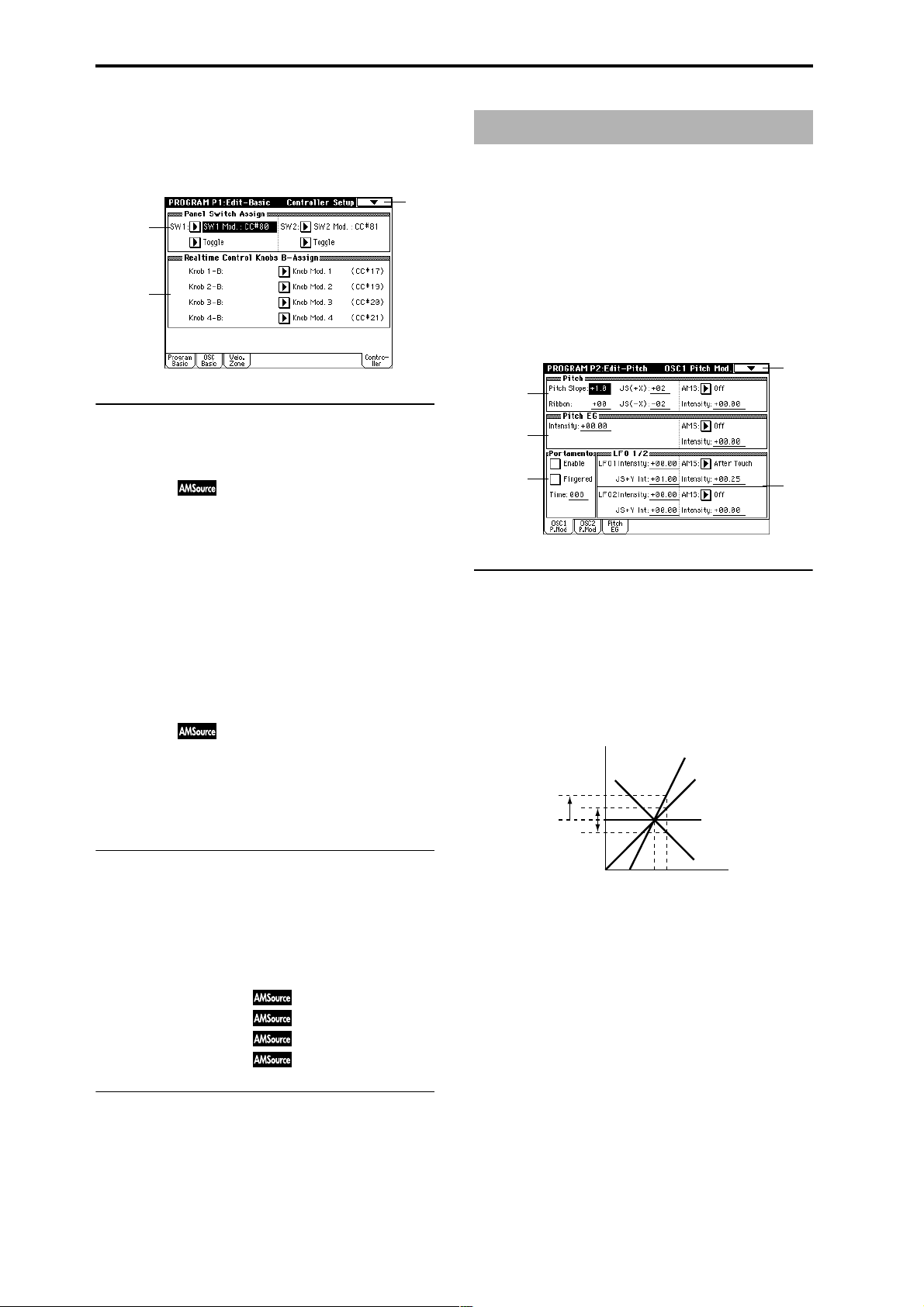
1–4: Controller (Controller Setup)
These settings specify the functions of the [SW1] key, the
[SW2] key, and the B-mode functions of REALTIME CONTROL knobs [1]–[4] in Program mode.
1–4
1–4a
1–4b
1–4a: Panel Switch Assign
These settings assign functions to the [SW1] and [SW2] keys
(“SW1, SW2 Assign List” ☞p.249).
SW1 Assign [Off, ..., After Touch Lock]
Assigns a function to the [SW1] key.
The on/off status of the switch is saved when the program is
written.
When you change the function, it will be reset to the “off”
state.
SW1 Mode [Toggle, Momentary]
Specifies how the on/off state of the [SW1] key will change
when it is pressed.
Toggle: On/off will alternate each time the [SW1] key is
pressed.
Momentary: The function will be on only as long as the
[SW1] key remains pressed.
SW2 Assign [Off, ..., After Touch Lock]
SW2 Mode [Toggle, Momentary]
Assigns a function to the [SW2] key.
The functions that can be assigned to [SW2] key are the
same as for [SW1] key, except that SW2 Mod.:CC#81 is
available instead of SW1 Mod.:CC#80.
Program P2: Edit–Pitch
Here you can make pitch modulation settings for oscillators
1 and 2.
2–1: OSC1 P.Mod (OSC1 Pitch Mod.)
These settings specify how key position (note number) will
affect the pitch of oscillator 1, and select the controllers that
will affect the oscillator 1 pitch and specify the depth of control. Here you can also specify the amount of pitch change
produced by the Pitch EG and by LFO1 and LFO2. You can
also switch portamento on/off and specify how it will apply.
2–1
2–1a
2–1b
2–1c
2–1a: Pitch
Pitch Slope [–1.0…+2.0]
Normally you will leave this at +1.0.
Positive (+) values will cause the pitch to rise as you play
higher on the keyboard, and negative (–) values will cause
the pitch to fall as you play higher on the keyboard.
With a value of 0, there will be no change in pitch, and the
C4 pitch will sound regardless of the key you play.
How the Pitch Slope and pitch are related
2oct
1oct
1oct
Pitch
+2
+1
0
2–1d
1–4b: Realtime Control Knobs B–Assign
Here you can assign functions (mainly various types of control change) to the B-mode of the REALTIME CONTROL
knobs [1]–[4] (“Realtime Control Knobs B–Assign List”
☞p.250).
The functions you set here will take effect when you operate
the REALTIME CONTROL knobs [1]–[4] in B-mode.
Knob 1–B
Knob 2–B
Knob 3–B
Knob 4–B
(Knob 1–B Assign)
(Knob 2–B Assign)
(Knob 3–B Assign)
(Knob 4–B Assign)
[Off, ..., MIDI CC#95]
[Off, ..., MIDI CC#95]
[Off, ..., MIDI CC#95]
[Off, ..., MIDI CC#95]
▼ 1–4: Page Menu Command
☞ 0–1A: Write Program, 1–1A: Copy Oscillator, 1–1B: Swap
Oscillator
12
–1
C4 C5
Key
Ribbon [–12…+12]
Specifies in semitone units how greatly the pitch will be
changed when you press the ribbon controller.
With a value of 12, the pitch can be changed a maximum of
one octave.
Positive (+) values will cause the pitch to rise when you
press the ribbon controller to the right of center, and nega-
tive (–) values will cause the pitch to fall.
For example with a setting of +12, pressing the far right edge
of the ribbon controller will raise the pitch one octave. With
a setting of –12, pressing the far right edge of the ribbon controller will lower the pitch one octave.
At the center of the ribbon controller, the original pitch will
remain, so you can use this in conjunction with pressing the
ribbon at its right edge to simulate the “hammering-on”
techniques used by guitarists.
Page 24
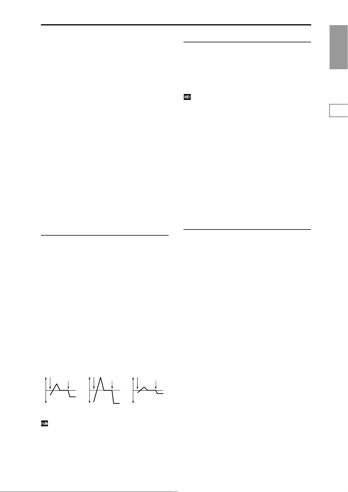
JS (+X) [–60…+12]
Specifies in semitone units how the pitch will change when
the joystick is moved all the way to the right. A setting of 12
produces 1 octave of change.
For example if you set this to +12 and move the joystick all
the way to the right, the pitch will rise one octave above the
original pitch.
JS (–X) [–60…+12]
Specifies in semitone units how the pitch will change when
the joystick is moved all the way to the left. A setting of 12
produces 1 octave of change.
For example if you set this to –60 and move the joystick all
the way to the left, the pitch will fall five octaves below the
original pitch. This can be used to simulate the downward
swoops that a guitarist produces using the tremolo arm.
AMS (Pitch AMS) [Off, (FEG, AEG, EXT)]
Selects the source that will modulate the pitch of oscillator 1
(“AMS List” ☞p.242).
Intensity (AMS Intensity) [–12.00…+12.00]
Specifies the depth and direction of the effect produced by
“AMS (Pitch AMS).”
With a setting of 0, no modulation will be applied. With a
setting of 12.00, the pitch will change up to one octave.
For example if you set “AMS (Pitch AMS)” to After Touch
and apply pressure to the keyboard, the pitch will rise if this
parameter is set to a positive (+) value, or fall if this parameter is set to a negative (–) value. The range is a maximum of
one octave (☞p.244).
2–1c: Portamento
This turns the portamento effect (smooth change in pitch
from one note to the next) on/off, and specifies how it will be
applied.
If [SW1] key or [SW2] key are set to Porta.SW:CC#65, turning
[SW1] key or [SW2] key on/off will apply portamento (“AMS
List” ☞p.242, “SW1, SW2 Assign List”, Porta.SW:#65).
Portamento will also be switched when CC#65 (Portamento SW) is received.
Enable (Porta. Enable) [Off, On]
On (checked): Portamento will be applied.
Off (unchecked): Portamento will not be applied.
Fingered (Porta. Fingered) [Off, On]
This parameter is available when “Enable (Porta. Enable)” is
checked.
On (checked): Portamento will be applied when you continue holding the previous note as you press the next note
(legato playing).
Off (unchecked): Portamento will always be applied,
regardless of how you play.
Time (Porta. Time) [000...127]
This parameter is available when “Enable (Porta. Enable)” is
checked.
This sets the portamento time. Increasing the value will produce a slower change in pitch.
Program
P0
P1 P2 P3 P4 P5 P7 P8 P9
2–1b: Pitch EG
Intensity [–12.00…+12.00]
Specifies the depth and direction of the modulation that the
pitch EG specified in P2: Edit-Pitch, Pitch EG page will
apply to the pitch.
With a setting of 12.00, the pitch will change a maximum of
±1 octave.
AMS (Pitch EG AMS) [Off, (KT, EXT)]
Selects the source that will control the pitch modulation
applied by the pitch EG (“AMS List” ☞p.242).
Intensity (AMS Intensity) [–12.00…+12.00]
Specifies the depth and direction of the effect that “AMS
(Pitch EG AMS)” will have.
For example if you set “AMS (Pitch EG AMS)” to Velocity
and set this value to 12.00, the velocity will control the range
of pitch change produced by the pitch EG in a range of ±1
octave (☞p.244). As you play more softly, the pitch change
will draw closer to the pitch EG levels.
Pitch change (level)
Note-on
Note-off
Softly played
(Intensity setting)
“Intensity” and “AMS (Pitch EG AMS)” will be added
to determine the depth and direction of the pitch modulation applied by the pitch EG.
Note-on
Note-off
Strongly played with
a positive (+) value
Note-on
Note-off
Strongly played with a
negative (–) value
2–1d: LFO1/2
LFO1:
LFO1 Intensity [–12.00…+12.00]
Specifies the depth and direction of the pitch modulation
applied by the OSC 1 LFO1 settings you made in “OSC1
LFO1” (5–1).
With a setting of 12.00, a maximum of ±1 octave of pitch
modulation will be applied. Negative (–) values will invert
the LFO waveform.
JS+Y Int. (LFO1 JS+Y Int.) [–12.00…+12.00]
Specifies the depth and direction of the effect that joystick
movement in the +Y direction (away from yourself) will
have on the pitch modulation applied by the OSC1 LFO1.
As this value is increased, moving the joystick in the +Y
direction will cause the OSC1 LFO1 to produce deeper pitch
modulation. With a setting of 12.00 a maximum of ±1 octave
of pitch modulation will be applied. Negative (–) values
will invert the LFO waveform.
AMS (LFO1 AMS) [Off, (PEG, FEG, AEG, KT, EXT)]
Selects the source that will control the depth of pitch modulation produced by the OSC1 LFO1 (“AMS List” ☞p.242).
Intensity (AMS Intensity) [–12.00…+12.00]
Specifies the depth and direction of the effect that “AMS
(LFO1 AMS)” will have.
With a setting of 0, modulation will not be applied. With a
setting of 12.00, the OSC1 LFO1 will apply a maximum of ±1
octave of pitch modulation. Negative (–) settings will invert
the LFO waveform.
For example if “AMS (LFO1 AMS)” is set to After Touch and
you apply pressure to the keyboard, a positive (+) setting of
this parameter will cause the pitch modulation created by OSC1
LFO1 to be applied with the normal phase, and a negative (–)
setting will cause the LFO to be applied with inverted phase.
13
Page 25
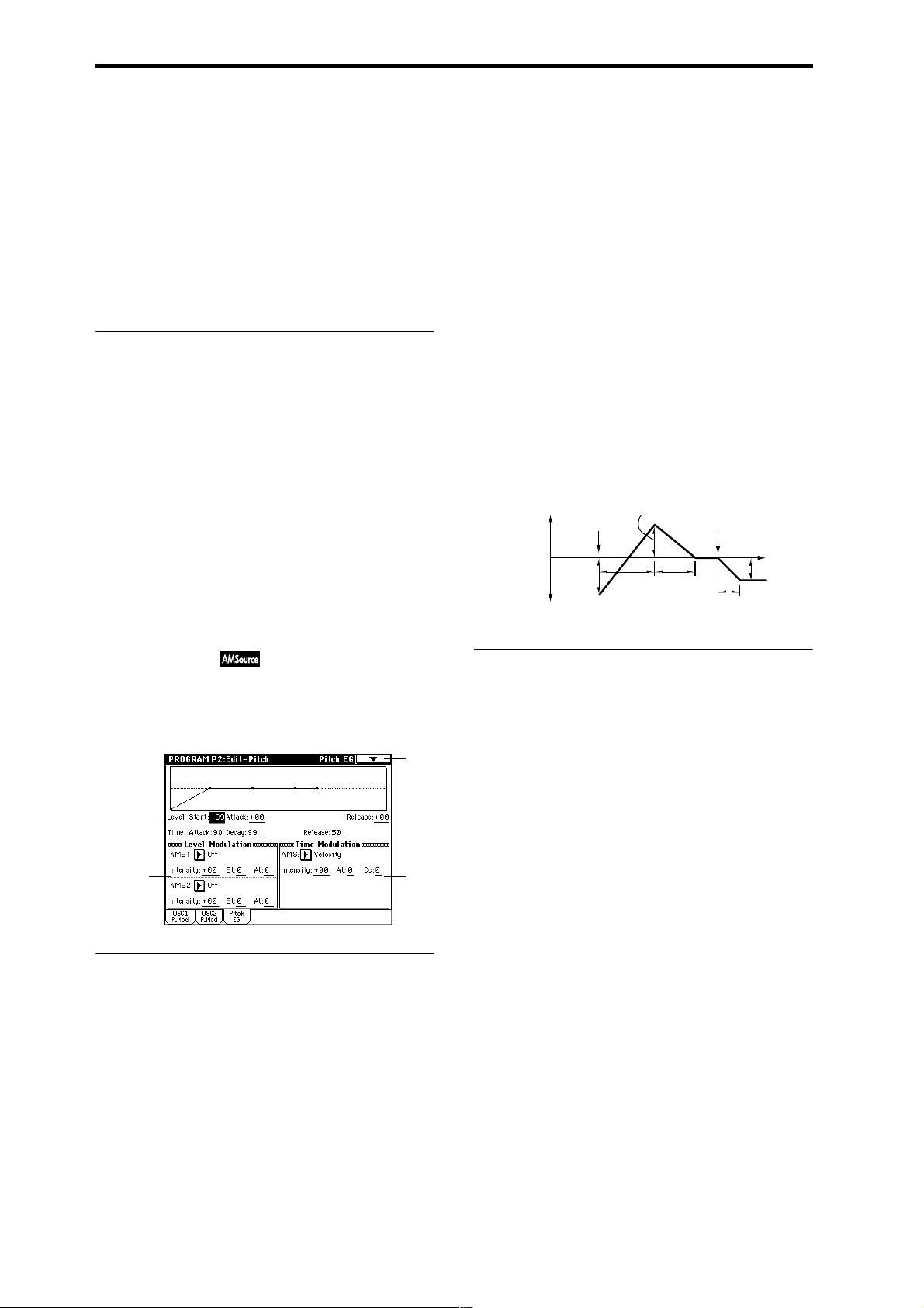
The “LFO1 Intensity,” “JS+Y (LFO1 JS+Y Int.)” and “AMS
(LFO1 AMS)” settings will be added to determine the depth
and direction of the pitch modulation applied by OSC1
LFO1 (☞p.244).
LFO2:
LFO2 Intensity [–12.00…+12.00]
JS+Y Int. (LFO2 JS+Y Int.) [–12.00…+12.00]
AMS (LFO2 AMS) [Off, (PEG, FEG, AEG, KT, EXT)]
Intensity (AMS Intensity) [–12.00…+12.00]
Refer to the above “LFO1.”
▼ 2–1: Page Menu Command
☞ 0–1A: Write Program, 1–1A: Copy Oscillator, 1–1B: Swap
Oscillator
Attack (Attack Level) [–99…+99]
Specifies the amount of pitch change when the attack time
has elapsed.
Release (Release Level) [–99…+99]
Specifies the amount of pitch change when the release time
has elapsed.
Time:
These parameters specify the amount of time over which the
pitch change will occur.
Attack (Attack Time) [0…99]
Specifies the time over which the pitch will change from
note-on until it reaches the pitch specified as the attack level.
Decay (Decay Time) [0…99]
Specifies the time over which the pitch will change after
reaching the attack level until it reaches the normal pitch.
2–2: OSC2 P.Mod (OSC2 Pitch Mod.)
These settings specify how key position (note number) will
affect the pitch, and select the controllers that will affect the
oscillator 2 pitch and specify the depth of control. They also
specify the depth at which the pitch EG will affect the pitch of
oscillator 2, and the depth of pitch change produced by LFO1
and LFO2. Portamento on/off settings etc. are also found
here.
For details on the functions of these parameters, refer to the
preceding section “2–1: OSC1 P.Mod (OSC1 Pitch Mod.).”
2–3: Pitch EG
Here you can make settings for the pitch EG, which creates
time-variant changes in the pitch of oscillators 1 and 2.
The depth of pitch change produced by these EG settings on
oscillator 1 (2) is adjusted by “Pitch EG” (2–1b, 2–2).
2–3
2–3a
2–3b
2–3a: Pitch EG
These settings specify how the pitch will change over time.
Level:
These parameters specify the amount of pitch change.
The actual amount of pitch change will depend on the
“Pitch EG” (2–1b, 2–2) parameter “Intensity.” For example
with an “Intensity” setting of +12.00, a “Level” setting of
+99 would raise the pitch one octave, and a “Level” setting
of –99 would lower the pitch one octave.
2–3c
Release (Release Time) [0…99]
Specifies the time over which the pitch will change from note-
off until it reaches the pitch specified as the release level.
Time-varying pitch settings (when Pitch EG Intensity = +12.00)
+99 = approximately 1 octave
0 = pitch when
key is held
(sustained)
Start Level
–99 = approximately 1 octave
Note-on
Attack
Time
Attack Level
Decay
Time
Note-off
Release Time
Time
Release Level
2–3b: Level Modulation
These settings allow the pitch EG Level parameters to be controlled by alternate modulation.
AMS1 (Level Mod. AMS1) [Off, (KT, EXT)]
Selects the source that will control the pitch EG Level parameters (“AMS List” ☞p.242).
Intensity (AMS1 Intensity) [–99…+99]
Specifies the depth and direction of the effect applied by
“AMS1 (Level Mod. AMS1).”
With a setting of 0, the levels specified by “Pitch EG” (2–3a)
will be used.
For example if “AMS1 (Level Mod. AMS1)” is SW1:CC#80,
pressing the [SW1] key to turn it on will change the Level
parameters of the Pitch EG. (Set “Panel Switch Assign” (1–
4a) to SW1 Mod.CC#80.) As the absolute value of “Intensity
(AMS1 Intensity)” is increased, the pitch EG levels will
change more greatly when the [SW1] key is turned on. The
direction of the change is specified by “St (AMS1 SW Start)”
and “At (AMS1 SW Attack).” When the [SW1] key is turned
off, the pitch EG levels will return to their own settings.
If “AMS1 (Level Mod. AMS1)” is set to Velocity, increasing
the absolute value of “Intensity (AMS1 Intensity)” will produce increasingly wider change in pitch EG levels for
strongly-played notes. The direction of the change is specified by “St (AMS1 SW Start)” and “At (AMS1 SW Attack).”
As you play more softly, the pitch change will draw closer to
the pitch EG levels.
Start (Start Level) [–99…+99]
Specifies the amount of pitch change at note-on.
14
Page 26
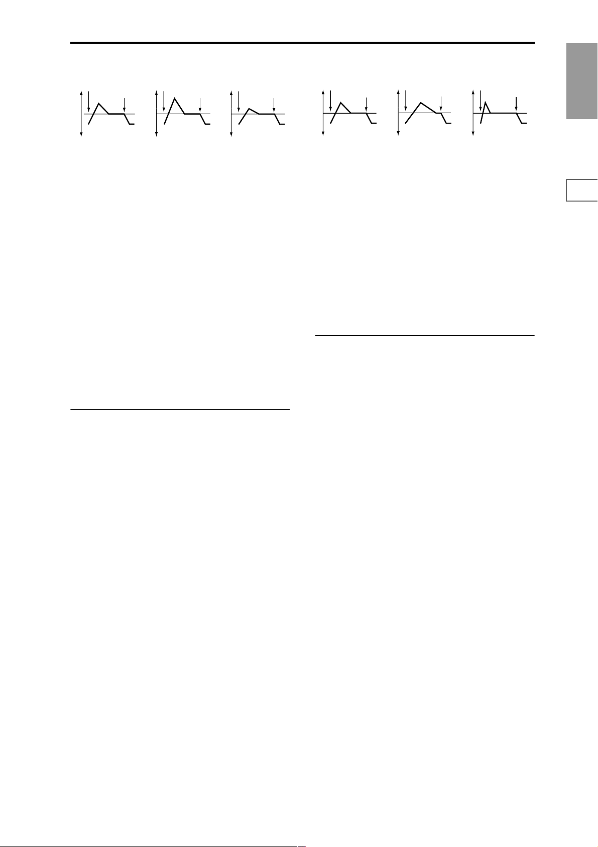
Pitch EG change (level) (AMS=SW1/Velocity, Intensity= positive (+) value
Note-on
Note-off
Note-on
Note-off
Note-on
Note-off
Pitch EG changes (Time) (AMS = Velocity, Intensity = positive (+) value)
Note-on
Note-off
Note-on
Note-off
Note-on
Note-off
Program
A note played softly with
“St” set at 0, “At” set to +,
and SW1 turned on (the
settings of 2–3a: Pitch EG)
A note played strongly with
“St” set to 0, “At” set to +,
and SW1 turned on
A note played strongly with
“St” set to 0, “At” set to –,
and SW1 turned on
St (AMS1 SW Start) [–, 0, +]
Specifies the direction of change in “Start (Start Level)”
caused by “AMS1 (Level Mod. AMS1).” If “Intensity
(AMS1 Intensity)” is a positive (+) value, a setting of + will
raise the EG level, and a setting of – will decrease it. With a
setting of 0 there will be no change.
At (AMS1 SW Attack) [–, 0, +]
Specifies the direction of change in “Attack (Attack Level)”
caused by “AMS1 (Level Mod. AMS1).” If “Intensity (AMS1
Intensity)” is a positive (+) value, a setting of + will raise the
EG level, and a setting of – will decrease it. With a setting of
0 there will be no change.
AMS2 (Level Mod. AMS2) [Off, (KT, EXT)]
Intensity (AMS2 Intensity) [–99…+99]
St (AMS2 SW Start) [–, 0, +]
At (AMS2 SW Attack) [–, 0, +]
Refer to the preceding paragraphs “AMS1 (Level Mod.
AMS1)”–“At (AMS1 SW Attack).”
2–3c: Time Modulation
A note played softly with “At”
set to + and “Dc” set to +
(settings of 2–3a: Pitch EG)
A note played strongly with
“At” set to + and “Dc” set to +
A note played strongly with
“At” set to – and “Dc” set to –
At (AMS SW Attack) [–, 0, +]
Specifies the direction in which “AMS (Time Mod. AMS)” will
affect the “Attack (Attack Time).” With positive (+) values of
“Intensity (AMS Intensity),” a setting of + will cause the time
to be lengthened, and a setting of – will cause the time to be
shortened. With a setting of 0 there will be no change.
Dc (AMS SW Decay) [–, 0, +]
Specifies the direction in which “AMS (Time Mod. AMS)”
will affect the “Decay (Decay Time).” With positive (+) values of “Intensity (AMS Intensity),” a setting of + will cause
the time to be lengthened, and a setting of – will cause the
time to be shortened. With a setting of 0 there will be no
change.
▼ 2–3: Page Menu Command
☞ 0–1A: Write Program, 1–1A: Copy Oscillator, 1–1B: Swap
Oscillator
P0
P1 P2 P3 P4 P5 P7 P8 P9
These parameters let you use an alternate modulation
source to control the Time parameters of the pitch EG.
AMS (Time Mod. AMS) [Off, (KT, EXT)]
Selects the source that will control the Time parameters of
the pitch EG (“AMS List” ☞p.242).
Intensity (AMS Intensity) [–99…+99]
Specifies the depth and direction of the effect that “AMS
(Time Mod. AMS)” will have.
With a setting of 0, the pitch EG times will be just as specified by the “Pitch EG” (2–3a) settings.
The alternate modulation value at the moment that the EG
reaches each point will determine the actual value of the EG
time that comes next.
For example, the decay time will be determined by the alternate modulation value at the moment that the attack level is
reached.
When this parameter is set to values of 16, 33, 49, 66, 82, or
99, the specified EG times will speed up as much as 2, 4, 8,
16, 32, or 64 times respectively (or slowed down to 1/2, 1/4,
1/8, 1/16, 1/32, or 1/64 of the original time).
For example if “AMS (Time Mod. AMS)” is set to Velocity,
increasing the absolute value of “Intensity (AMS Intensity)”
will allow strongly-played notes to increase the changes in
pitch EG Time values. The direction of the change is specified by “At (AMS SW Attack)” and “Dc (AMS SW Decay).”
As you play more softly, the pitch EG times will more
closely approach the actual settings of the pitch EG.
15
Page 27
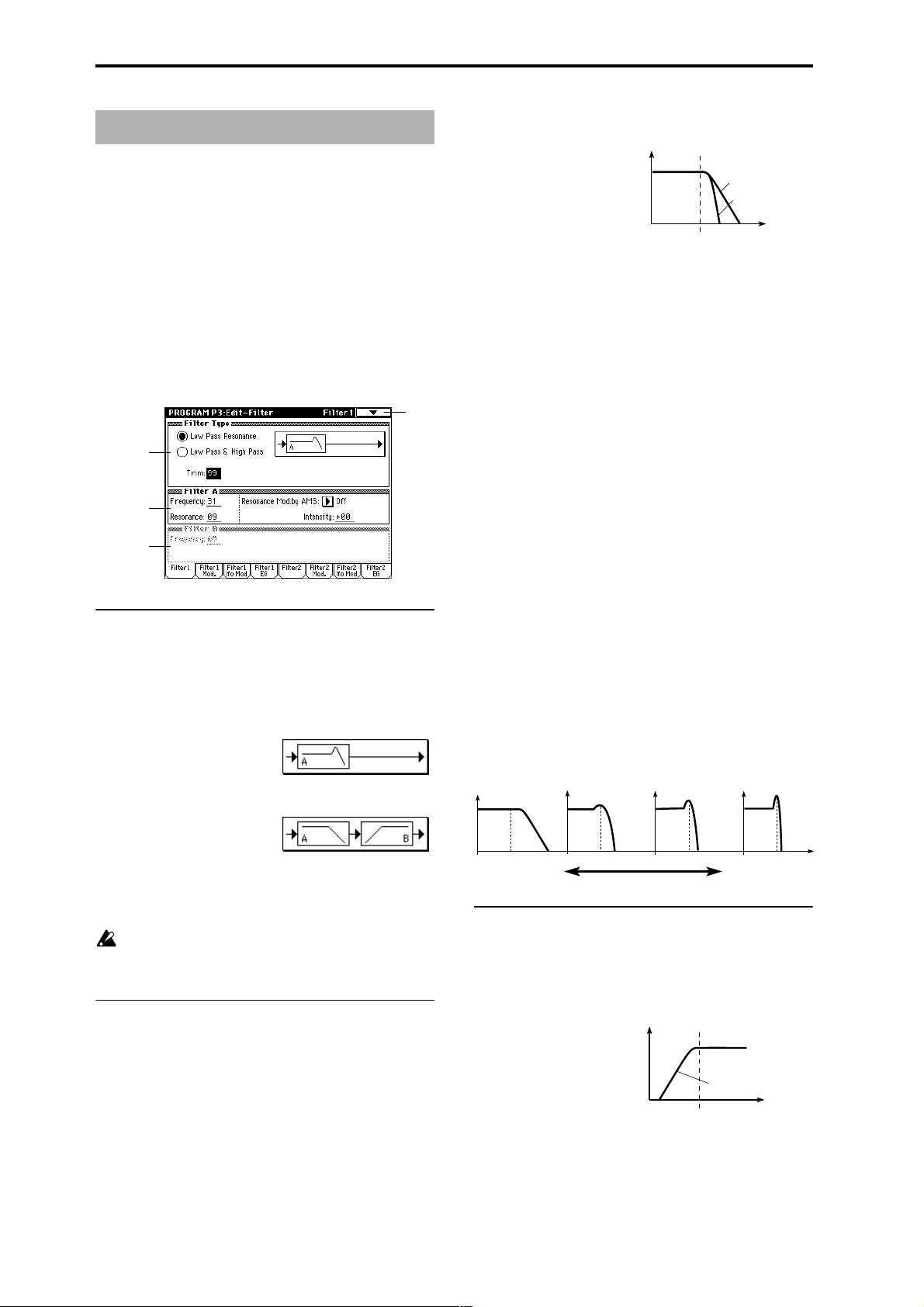
Program P3: Edit–Filter
Here you can make settings for the filters that will be used by
oscillators 1 and 2. You can select either a 24 dB/octave low
pass filter with resonance, or a series connection of a 12 dB/
octave low pass filter and a 12 dB/octave high pass filter.
When “Oscillator Mode” (1–1a) is set to Single, filter 1 will
be used, and when it is set to Double, filters 1 and 2 will be
used.
When Single is selected, pages relating to filter 2 cannot be
selected.
3–1: Filter1
Here you can specify the basic filter type used by oscillator
1, and set the cutoff frequency and resonance.
3–1
3–1a
3–1b
3–1c
3–1a: Filter Type
Filter Type
[Low Pass Resonance, Low Pass & High Pass]
Selects the type for filter 1.
Low Pass Resonance: 24 dB/octave low pass filter with res-
onance.
Low Pass & High Pass: 12 dB/octave low pass filter and 12
dB/octave high pass filter in series.
When the “Filter Type” is Low Pass Resonance, the cutoff
will have a steeper slope.
Low Pass
Level
12dB/oct
24dB/oct
Frequency
Frequency (A Frequency) [00…99]
Specifies the cutoff frequency of filter 1A.
Resonance (A Resonance) [00…99]
This emphasizes the overtone components that lie in the
region of the cutoff frequency specified by “Frequency (A
Frequency),” producing a more distinctive sound. Increasing this value will produce a stronger effect.
Resonance Mod. by AMS
[Off, (PEG, FEG, AEG, LFO, KT, EXT)]
Selects the source that will control the “Resonance (A Resonance)” level (“AMS List” ☞p.242).
Intensity (AMS Intensity) [–99…+99]
Specifies the depth and direction of the effect that “Resonance Mod. by AMS” will have on the resonance level specified by “Resonance (A Resonance).”
For example if Velocity has been selected, changes in key-
board velocity will affect the resonance.
With positive (+) values, the resonance will increase as you
play more strongly, and as you play more softly the resonance will approach the level specified by the “Resonance
(A Resonance)” setting.
With negative (–) values, the r esonance will decr ease as you
play more strongly, and as you play more softly the resonance will approach the level specified by the “Resonance
(A Resonance)” setting.
The resonance level is determined by adding the “Resonance (A Resonance)” and “Intensity (AMS Intensity)” values.
The effect of resonance
Low Pass
Level
Trim [00…99]
Adjusts the level at which the audio signal output from
oscillator 1 is input to filter 1A.
If the trim value is set too high, the sound may be distorted if Resonance is set to a high value or when you
play a chord.
3–1b: Filter A
This is a filter that cuts the high-frequency region above the
cutoff frequency.
This is the most common type of filter, and is used to cut
part of the overtone components, making an originally
bright timbre sound more mellow (darker).
16
Low resonance value High resonance value
3–1c: Filter B
This parameter will be displayed when “Filter Type” (3–1a)
is set to Low Pass & High Pass.
This filter cuts the low-frequency range that lies below the
cutoff frequency. By cutting the lower overtones, it lightens
the tone.
High Pass
Level
12dB/oct
Frequency
Frequency (B Frequency) [00…99]
Specifies the cutoff frequency of filter 1B.
Page 28
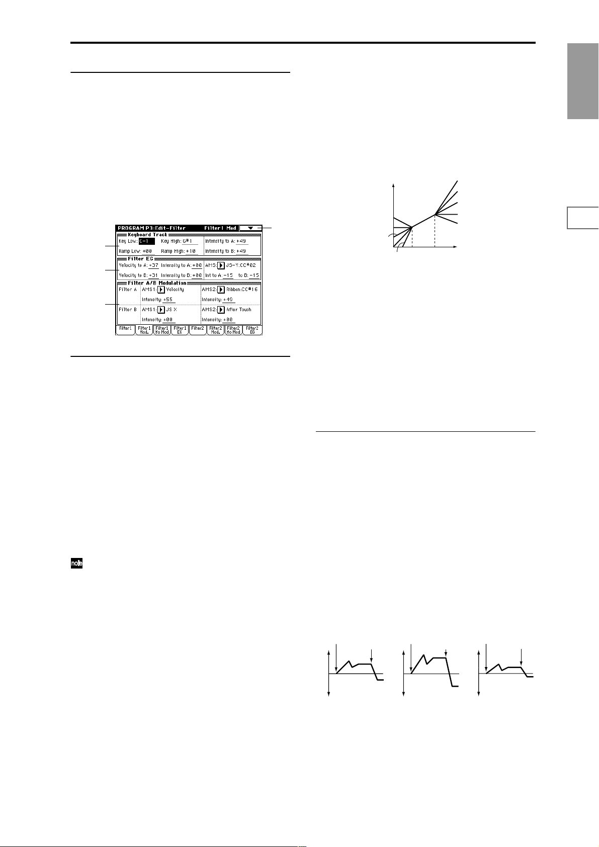
▼ 3–1: Page Menu Command
☞ 0–1A: Write Program, 1–1A: Copy Oscillator, 1–1B: Swap
Oscillator
3–2: Filter1 Mod.
Here you can make settings to specify how keyboard tracking, controllers, and filter 1 EG intensity will control the Filter 1 cutoff frequency “Frequency” (A/B Frequency) to
modify the tone.
When “Filter Type” (3–1a) is Low Pass Resonance, parameters for filter B will not be displayed.
3–2
3–2a
3–2b
3–2c
3–2a: Keyboard Track
These settings specify keyboard tracking for the cutoff frequency of filter 1.
The way in which the cutoff frequency is affected by the
position of the key you play (note number) can be specified
by the “Key Low (KBDTrk Key Low),” “Key High (KBDTrk
Key High),” “Ramp Low (KBDTrk Ramp Low)” and “Ramp
High (KBDTrk Ramp High)” parameters.
Key:
Specifies the note number at which keyboard tracking will
begin to be applied, and set the “Intensity to A (KBDTrk Int.
to A)” and “Intensity to B (KBDTrk Int. to B)” parameters to
specify the depth and direction of the change applied to filter 1 A and B.
For the range of notes between “Key Low (KBDTrk Key
Low)” and “Key High (KBDTrk Key High),” the cutoff frequency will change according to the key position (pitch).
Note numbers can also be entered by holding down the
[ENTER] key while you press a note on the keyboard.
Key Low (KBDTrk Key Low) [C–1…G9]
Keyboard tracking will apply to the range below the specified note number.
Key High (KBDTrk Key High) [C–1…G9]
Keyboard tracking will apply to the range above the specified note number.
increase the “Resonance (A Resonance)” (3–1b) will correspond to the keyboard location.
If you set “Ramp Low (KBDTrk Ramp Low)” to +43 and
“Ramp High (KBDTrk Ramp High)” to –43, the cutoff fre-
quency will not be affected by keyboard location. Use this
setting when you do not want the cutoff frequency to
change for each note.
How cutoff frequency is affected by keyboard location and the Ramp
setting
(“Intensity to A” and “Intensity to B” = +50)
Cutoff frequency
Low Ramp=+99
Low Ramp=+43
Low Ramp=0
Low Ramp=–62
Low Ramp=–99
Low Key
High Key
High Ramp=+99
High Ramp=+62
High Ramp=0
High Ramp=–43
High Ramp=–99
Key
Intensity to A (KBDTrk Int. to A) [–99…+99]
Specifies the depth and direction of the effect that the keyboard tracking specified by “Key Low (KBDTrk Key Low),”
“Key High (KBDTrk Key High),” “Ramp Low (KBDTrk
Ramp Low)” and “Ramp High (KBDTrk Ramp High)” will
have on filter 1A.
With positive (+) values, the effect will be in the direction
specified by keyboard tracking, and with negative (–) val-
ues the effect will be in the opposite direction.
Intensity to B (KBDTrk Int. to B) [–99…+99]
Specifies the depth and direction of the effect that keyboard
tracking will have on filter 1B (☞“Intensity to A (KBDTrk
Int. to A)”).
3–2b: Filter EG
Velocity to A [–99…+99]
This parameter specifies the depth and direction of the effect
that velocity will have on the time-varying changes created
by the filter 1 EG (as set by “Filter 1 EG” 3–4) to control the
filter 1A cutoff frequency.
With positive (+) values, playing more strongly will cause
the filter 1 EG to produce greater changes in cutoff frequency . W ith negative (–) values, playing mor e strongly will
also cause the filter 1 EG to produce greater changes in cutoff frequency, but with the polarity of the EG inverted.
Velocity to B [–99…+99]
This parameter specifies the depth and direction of the effect
that velocity will have on the time-varying changes created
by the filter 1 EG to control the filter 1B cutoff frequency (☞
“Velocity to A”).
Changes in cutoff frequency
Note-on
Note-off
Note-on
Note-off
Note-on
Note-off
Program
P0
P1 P2 P3 P4 P5 P7 P8 P9
Ramp (Ramp Setting):
Specifies the angle of keyboard tracking.
Ramp Low (KBDTrk Ramp Low) [–99…+99]
Ramp High (KBDTrk Ramp High) [–99…+99]
If “Intensity to A (KBDTrk Int. to A)” and “Intensity to B
(KBDTrk Int. to B)” are set to +50, “Ramp Low (KBDTrk
Ramp Low)” is set to –62 and “Ramp High (KBDTrk Ramp
High)” is set to +62, the angle of the change in cutoff fre-
quency will correspond to the keyboard location (pitch).
This means that the oscillation that occurs when you
Softly played
(The setting of 3–2b: Intensity to A)
Strongly played
Setting to +
Strongly played
Setting to –
Intensity to A [–99…+99]
Specifies the depth and direction of the effect that the timevarying changes created by the filter 1 EG will have on the
filter 1A cutoff frequency.
With positive (+) settings, the sound will become brighter
when the EG levels set by Filter 1 EG Level and Time parame-
17
Page 29
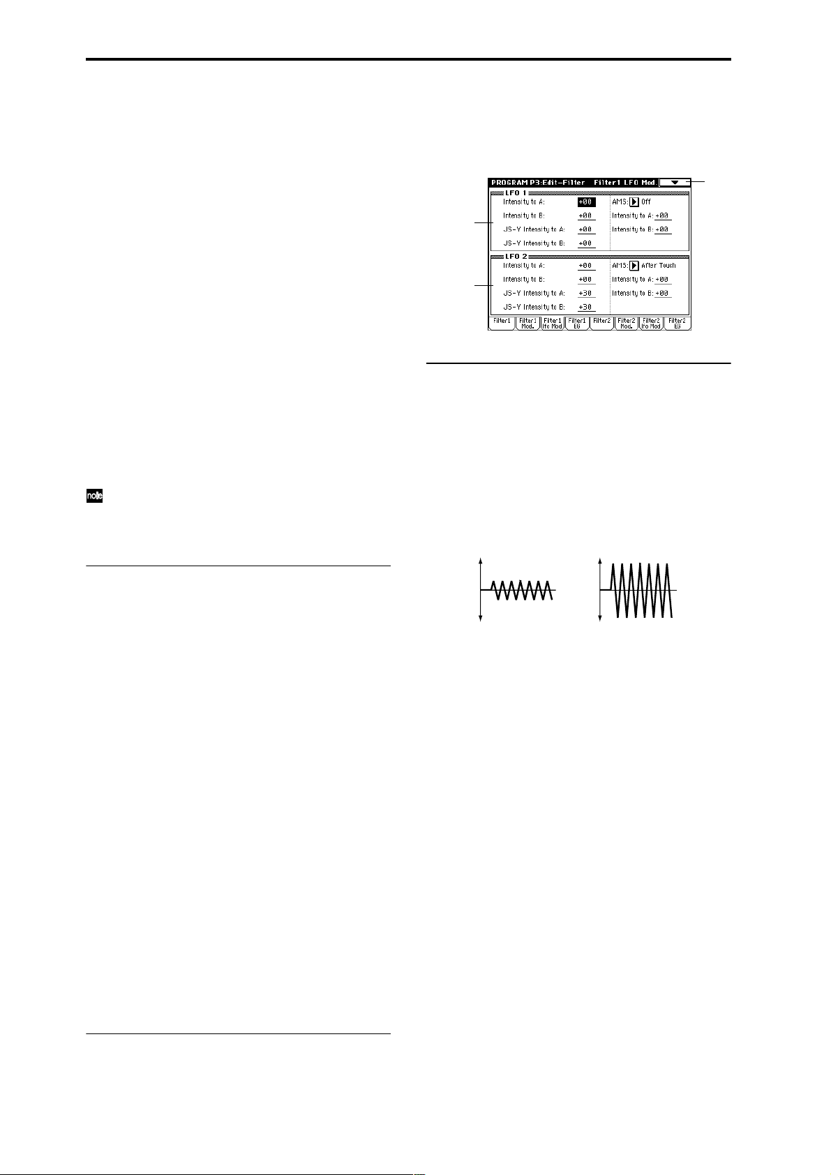
ters (3–4a) are in the “+” area, and darker when they are in
the “–” area.
With negative (–) settings, the sound will become darker
when the EG levels set by Filter 1 EG “Level” and “Time”
parameters (3–4a) are in the “+” area, and brighter when
they are in the “–” area.
Intensity to B [–99…+99]
Specifies the depth and direction of the effect that the timevarying changes created by the filter 1 EG will have on the
filter 1B cutoff frequency (☞“Intensity to A”).
AMS (Filter EG AMS) [Off, (EXT)]
Selects the source that will control the depth and direction of
the effect that the time-varying changes produced by the filter 1 EG will have on the cutoff frequency of filters 1A and
1B (“AMS List” ☞p.242).
Int to A (AMS Int. to A) [–99…+99]
Specifies the depth and direction of the effect that “AMS
(Filter EG AMS)” will have on filter 1A. For details on how
this will apply (☞“Intensity to A”).
Int to B (AMS Int. to B) [–99…+99]
Specifies the depth and direction of the effect that “AMS
(Filter EG AMS)” will have on filter 1B. For details on how
this will apply (☞“Intensity to A”).
The sum of the settings for “Velocity to A (B),” “Intensity to A (B),” and “Int to A (B) (AMS Int. to A/B)” will
determine the depth and direction of the effect produced by the filter EG.
3–3: Filter1 LFO Mod.
Here you can use the filter 1 LFO to apply cyclic modulation
to the cutoff frequency of filter 1 (for oscillator 1) to create
cyclical changes in tone.
3–3
3–3a
3–3b
3–3a: LFO 1
Intensity to A (LFO1 Int. to A) [–99…+99]
Specifies the depth and direction of the modulation that
OSC1 LFO1 (set by “OSC1 LFO1” 5–1) will have on the cutoff frequency of filter 1A.
Negative (–) settings will invert the phase.
Intensity to B (LFO1 Int. to B) [–99…+99]
Specifies the depth and direction of the modulation that
OSC1 LFO1 will have on the cutoff frequency of filter 1B
(☞“Intensity to A (LFO1 Int. to A)”).
Change in cutoff
3–2c: Filter A/B Modulation
Filter A:
AMS1 (Filter A AMS1) [Off, (PEG, AEG, EXT)]
Selects the source that will control modulation of the filter
1A cutoff frequency (“AMS List” ☞p.242).
Intensity (A AMS1 Intensity) [–99…+99]
Specifies the depth and direction of the effect that “AMS1
(Filter A AMS1)” will have.
When “AMS1 (Filter A AMS1)” is JS X, a positive (+) value
for this parameter will cause the cutoff frequency to rise
when the joystick is moved toward the right, and fall when
the joystick is moved toward the left. With a negative (–)
value for this parameter, the opposite will occur.
This value is added to the setting of the Filter A “Frequency
(A Frequency)” (3–1b).
AMS2 (Filter A AMS2) [Off, (PEG, AEG, EXT)]
Intensity (A AMS2 Intensity) [–99…+99]
Selects “AMS2 (Filter A AMS2),” and specify the depth and
direction of the effect that the selected source will have
(☞“AMS1 (Filter A AMS1),” “Intensity (A AMS1 Intensity)”).
Filter B:
This will be displayed when “Filter Type” (3–1a) is Low
Pass & High Pass.
Two alternate modulation sources can be used to modulate
the cutoff frequency of filter 1B (☞“Filter A”).
▼ 3–2: Page Menu Command
Low setting High setting
JS–Y Intensity to A (LFO1 JS–Y Int. to A) [–99...+99]
The joystick can be moved in the –Y direction (toward yourself) to control OSC1 LFO1, modulating the cutoff frequency
of filter 1A.
This parameter specifies the depth and direction of control.
Higher settings of this parameter will cause OSC1 LFO1 to
have a greater effect on filter 1 when you move the joystick
in the –Y direction (toward yourself).
JS–Y Intensity to B (LFO1 JS–Y Int. to B) [–99...+99]
The joystick can be moved in the –Y direction (toward yourself) to control OSC1 LFO1, modulating the cutoff frequency
of filter 1B.
This parameter specifies the depth and direction of control.
(☞”JS–Y Intensity to A (LFO1 JS–Y Int. to A)”)
AMS (LFO1 AMS) [Off, (PEG, FEG, AEG, KT, EXT)]
Selects a source that will control the depth and direction of
cutoff frequency change for both filters 1A and 1B (“AMS
List” ☞p.242).
Intensity to A (LFO1 AMS Int. to A) [–99…+99]
Specifies the depth and direction of the effect that “AMS
(LFO1 AMS)” will have on filter 1A.
For example if “AMS (LFO1 AMS)” is After Touch, higher
settings of this parameter will allow greater change to be
applied to OSC1 LFO1 when you apply pressure to the keyboard.
☞ 0–1A: Write Program, 1–1A: Copy Oscillator, 1–1B: Swap
Oscillator
18
Page 30
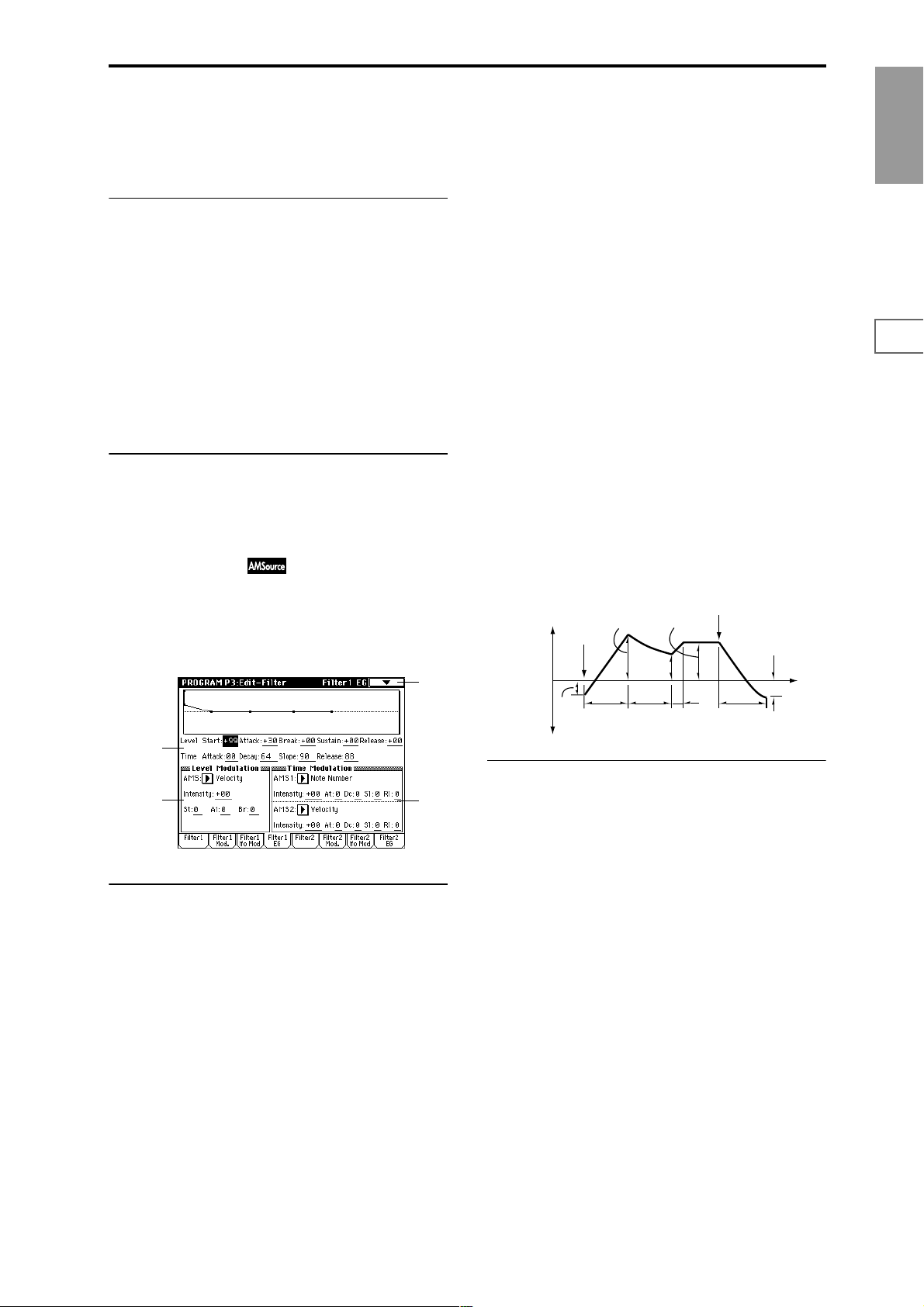
Intensity to B (LFO1 AMS Int. to B) [–99…+99]
Specifies the depth and direction of the effect that “AMS
(LFO1 AMS)” will have on filter 1B (☞“Intensity to A (LFO1
AMS Int. to A)”).
3–3b: LFO 2
Adjusts the depth of the cyclic modulation applied by OSC1
LFO2 (set by 5–2) to the cutoff frequency of filters 1A and 1B
(☞LFO 1: 3–3a).
Intensity to A (LFO2 Int. to A) [–99…+99]
Intensity to B (LFO2 Int. to B) [–99…+99]
JS–Y Intensity to A (LFO2 JS–Y Int. to A) [–99…+99]
JS–Y Intensity to B (LFO2 JS–Y Int. to B) [–99…+99]
AMS (LFO2 AMS) [Off, (PEG, FEG, AEG, KT, EXT)]
Intensity to A (LFO2 AMS Int. to A) [–99…+99]
Intensity to B (LFO2 AMS Int. to B) [–99…+99]
▼ 3–3: Page Menu Command
Break (Break Point Level) [–99…+99]
Specifies the cutoff frequency after the decay time has
elapsed.
Sustain (Sustain Level) [–99…+99]
Specifies the cutoff frequency that will be maintained from
after the slope time has elapsed until note-off occurs.
Release (Release Level) [–99…+99]
Specifies the cutoff frequency that will occur when the
release time has elapsed.
Time:
These parameters specify the time over which each change
will occur.
Attack (Attack Time) [00…99]
Specifies the time over which the level will change from
note-on until the attack level is reached.
Decay (Decay Time) [00…99]
Specifies the time over which the level will change from the
attack level to the break point level.
Program
P0
P1 P2 P3 P4 P5 P7 P8 P9
☞ 0–1A: Write Program, 1–1A: Copy Oscillator, 1–1B: Swap
Oscillator
3–4: Filter1 EG
Here you can make settings for the EG that will produce
time-varying changes in the cutoff frequency of filters 1A
and 1B.
The depth of the effect that these settings will have on the
filter 1 cutoff frequency is determined by Filter EG (3–2b).
3–4
3–4a
3–4b
3–4a: Filter1 EG
Specifies the time-varying change produced by the filter 1
EG.
Level:
The result will depend on the filter that was selected in “Fil-
ter T ype” (3–1a). For example with the Low Pass Resonance
filter, positive (+) values of EG Intensity will cause the tone
to be brightened by positive (+) levels, and darkened by
negative (–) levels.
Start (Start Level) [–99…+99]
Specifies the cutoff frequency at the time of note-on.
Attack (Attack Level) [–99…+99]
Specifies the cutoff frequency after the attack time has
elapsed.
3–4c
Slope (Slope Time) [00…99]
Specifies the time over which the level will change after the
decay time has elapsed until the sustain level is reached.
Release (Release Time) [00…99]
Specifies the time over which the level will change after
note-on occurs until the release level is reached.
Note-off
Break
Point
Level
Decay
Time
Sustain Level
Slope
Time
Release
Time
Release
Level
Time
The specified
cutoff
frequency
Start
Level
Note-on
Attack Level
Attack
Time
3–4b: Level Modulation
These settings let you use alternate modulation to control
the Level parameters of the filter 1 EG.
AMS (Level Mod. AMS) [Off, (KT, EXT)]
Selects the source that will control the Level parameters of
the filter 1 EG (“AMS List” ☞p.242).
Intensity (AMS Intensity) [–99…+99]
Specifies the depth and direction of the effect that “AMS
(Level Mod. AMS)” will have.
For example if “AMS (Level Mod. AMS)” is Velocity, and
you set “St (AMS SW Start),” “At (AMS SW Attack)” and
“Br (AMS SW Break)” to + and set “Intensity (AMS Intensity)” to a positive (+) value, the EG levels will rise as you
play more strongly. If “Intensity (AMS Intensity)” is set to a
negative (–) values, the EG levels will fall as you play more
strongly.
With a setting of 0, the levels specified by “Filter 1 EG” (3–
4a) will be used.
St (AMS SW Start) [–, 0, +]
Specifies the direction in which “AMS (Level Mod. AMS)”
will affect “Start (Start Level).” When “Intensity (AMS
Intensity)” has a positive (+) value, a setting of + for this
parameter will allow “AMS (Level Mod. AMS)” to raise the
EG level, and a setting of – will allow “AMS (Level Mod.
AMS)” to lower the EG level. With a setting of 0 there will be
no change.
19
Page 31

At (AMS SW Attack) [–, 0, +]
Specifies the direction in which “AMS (Level Mod. AMS)”
will affect “Attack (Attack Level).” When “Intensity (AMS
Intensity)” has a positive (+) value, a setting of + for this
parameter will allow “AMS (Level Mod. AMS)” to raise the
EG level, and a setting of – will allow “AMS (Level Mod.
AMS)” to lower the EG level. With a setting of 0 there will be
no change.
Br (AMS SW Break) [–, 0, +]
Specifies the direction in which “AMS (Level Mod. AMS)”
will affect “Break (Break Point Level).” When “Intensity
(AMS Intensity)” has a positive (+) value, a setting of + for
this parameter will allow “AMS (Level Mod. AMS)” to raise
the EG level, and a setting of – will allow “AMS (Level Mod.
AMS)” to lower the EG level. With a setting of 0 there will be
no change.
Filter 1 EG changes (level) (AMS = Velocity, Intensity = a positive (+) value)
Note-on
Softly played note with “St,”
“At,” and “Br” set to + (setting
of 3–4a: Filter 1 EG)
Note-off
Note-on
Strongly played note with
“St,” “At,” and “Br” set to +
Note-off
Note-on
Strongly played note with
“St,” “At,” and “Br” set to –
Note-off
3–4c: Time Modulation
Dc (AMS1 SW Decay) [–, 0, +]
Specifies the direction in which “AMS1 (Time Mod. AMS1)”
will affect the decay time. With positive (+) values of
“Intensity (AMS1 Intensity),” setting this parameter to +
will allow AMS1 to lengthen the time, and setting this
parameter to – will allow AMS1 to shorten the time. With a
setting of 0 there will be no change.
Sl (AMS1 SW Slope) [–, 0, +]
Specifies the direction in which “AMS1 (Time Mod. AMS1)”
will affect the slope time. With positive (+) values of “Inten-
sity (AMS1 Intensity),” setting this parameter to + will
allow AMS1 to lengthen the time, and setting this parameter
to – will allow AMS1 to shorten the time. With a setting of 0
there will be no change.
Rl (AMS1 SW Release) [–, 0, +]
Specifies the direction in which “AMS1 (Time Mod. AMS1)”
will affect the release time. With positive (+) values of
“Intensity (AMS1 Intensity),” setting this parameter to +
will allow AMS1 to lengthen the time, and setting this
parameter to – will allow AMS1 to shorten the time. With a
setting of 0 there will be no change.
Filter 1 EG changes (Time) (AMS = Velocity, Intensity = a positive (+) value)
Note-on
Note-off
Note-on
Note-off
Note-on
Note-off
These settings let you use alternate modulation to control
the Time parameters of the filter 1 EG.
AMS1:
AMS1 (Time Mod. AMS1) [Off, (KT, EXT)]
Selects the source that will control the Time parameters of
the filter 1 EG (“AMS List” ☞p.242).
Intensity (AMS1 Intensity) [–99…+99]
Specifies the depth and direction of the effect that “AMS1
(Time Mod. AMS1)” will have.
For example if “AMS1 (Time Mod. AMS1)” is set to Flt KTr
+/+, the EG Time parameters will be controlled by the Key-
board Track (3–2a) settings. With positive (+) values of this
parameter, positive (+) values of Ramp (Ramp Setting) will
lengthen the EG times, and negative (–) values of Ramp
(Ramp Setting) will shorten the EG times. The direction of
change is specified by “At (AMS1 SW Attack),” “Dc (AMS1
SW Decay),” “Sl (AMS1 SW Slope),” and “Rl (AMS1 SW
Release).”
With a setting of 0, the times specified by Filter 1 EG (3–4a)
will be used.
If “AMS1 (Time Mod. AMS1)” is set to Velocity, positive
(+) values of this parameter will cause EG times to lengthen
as you play more strongly, and negative (–) values will
cause EG times to shorten as you play more strongly.
At (AMS1 SW Attack) [–, 0, +]
Specifies the direction in which “AMS1 (Time Mod. AMS1)”
will affect the attack time. With positive (+) values of
“Intensity (AMS1 Intensity),” setting this parameter to +
will allow AMS1 to lengthen the time, and setting this
parameter to – will allow AMS1 to shorten the time. With a
setting of 0 there will be no change.
Softly played note with “At,”
“Dc,” “Sl” and “Rl” set to +
(setting of 3–4a: Filter 1 EG)
Strongly played note with
“At,” “Dc,” “Sl” and “Rl” set
to +
Strongly played note with
“At,” “Dc,” “Sl” and “Rl” set
to –
AMS2:
AMS2 (Time Mod. AMS2) [Off, (KT, EXT)]
Intensity (AMS2 Intensity) [–99…+99]
At (AMS2 SW Attack) [–, 0, +]
Dc (AMS2 SW Decay) [–, 0, +]
Sl (AMS2 SW Slope) [–, 0, +]
Rl (AMS2 SW Release) [–, 0, +]
These parameters are the settings for AMS2 to control the
Time parameters of the filter 1 EG (☞AMS1).
▼ 3–4: Page Menu Command
0–1A
1–1A
1–1B
3–4A
3–4A: Sync Both EGs
When you select the page menu command “Sync Both
EGs,” a check mark will be added at the left of “Sync Both
EGs.” In this state, you can edit the filter 1 EG and filter 2 EG
simultaneously. (Editing either EG will change the settings
of both EGs.)
“Sync Both EGs” cannot separately sync the filter EG
and amp EG. For example if they are synced in 4–3A,
they will also be synced here.
This can be selected only if “Oscillator Mode” (1–1a) is
Double.
20
Page 32

3–5: Filter2 3–6: Filter2 Mod. 3–7: Filter2 LFO Mod. 3–8: Filter2 EG
Make settings for filter 2 which controls the sound of oscillator 2. You can choose either a 24 dB/octave low pass filter
with resonance or a 12 dB/octave low pass filter and 12 dB/
octave high pass filter connected in series. Filter 2 can be
used if “Oscillator Mode” (1–1a) is Double. (☞”3–1:
Filter1” – “3–4: Filter1 EG”)
Program P4: Edit–Amp
Make settings for amp 1 which controls the volume of oscillator 1, and amp 2 which controls the volume of oscillator 2.
Pan settings are also made here.
4–1
4–1a
4–1b
4–1: Amp1 Level/Pan
These parameters control the volume and pan of oscillator 1.
4–1a: Amp Level
Amp Level (Amp1 Level) [0…127]
Sets the volume of oscillator 1.
The volume of a program can be controlled by CC#7
(volume) and #11 (expression). The resulting level is
determined by multiplying the values of CC#7 and #11.
The Global MIDI channel “MIDI Channel” (Global P1:
1–1a) is used for control.
Program
P0
P1 P2 P3 P4 P5 P7 P8 P9
4–1b: Pan
Pan (Amp1 Pan) [Random, L001…C064…R127]
Sets the pan (stereo location) of oscillator 1.
A setting of L001 places the sound at far left, C064 in the
center, and R127 to far right.
Random: The sound will be heard from a different location
at each note-on.
This can be controlled by CC#10 (panpot). A CC#10
value of 0 or 1 will place the sound at the far left, a
value of 64 will place the sound at the location specified
by the “Pan” setting for each oscillator, and a value of
127 will place the sound at the far right. This is controlled on the global MIDI channel “MIDI Channel”
(Global P1: 1–1a).
Use DKit Setting [Off, On]
This option is availble only when “Oscillator Mode” (1–1a)
is set to Drums.
On (checked): The sound will be output at the “Pan” setting
that has been made for each key of the drum kit (Global P5:
5–2b). When “Oscillator Mode” is Drums, you will normally use this setting.
Off (unchecked): All keys of the Drum Kit will use the “Pan
(Amp 1 Pan)” setting.
AMS (Pan AMS) [Off, (PEG, FEG, AEG, LFO, KT, EXT)]
Selects the source that will modify pan (“AMS List”
☞p.242). This change will be relative to the “Pan (Amp1
Pan)” setting.
21
Page 33
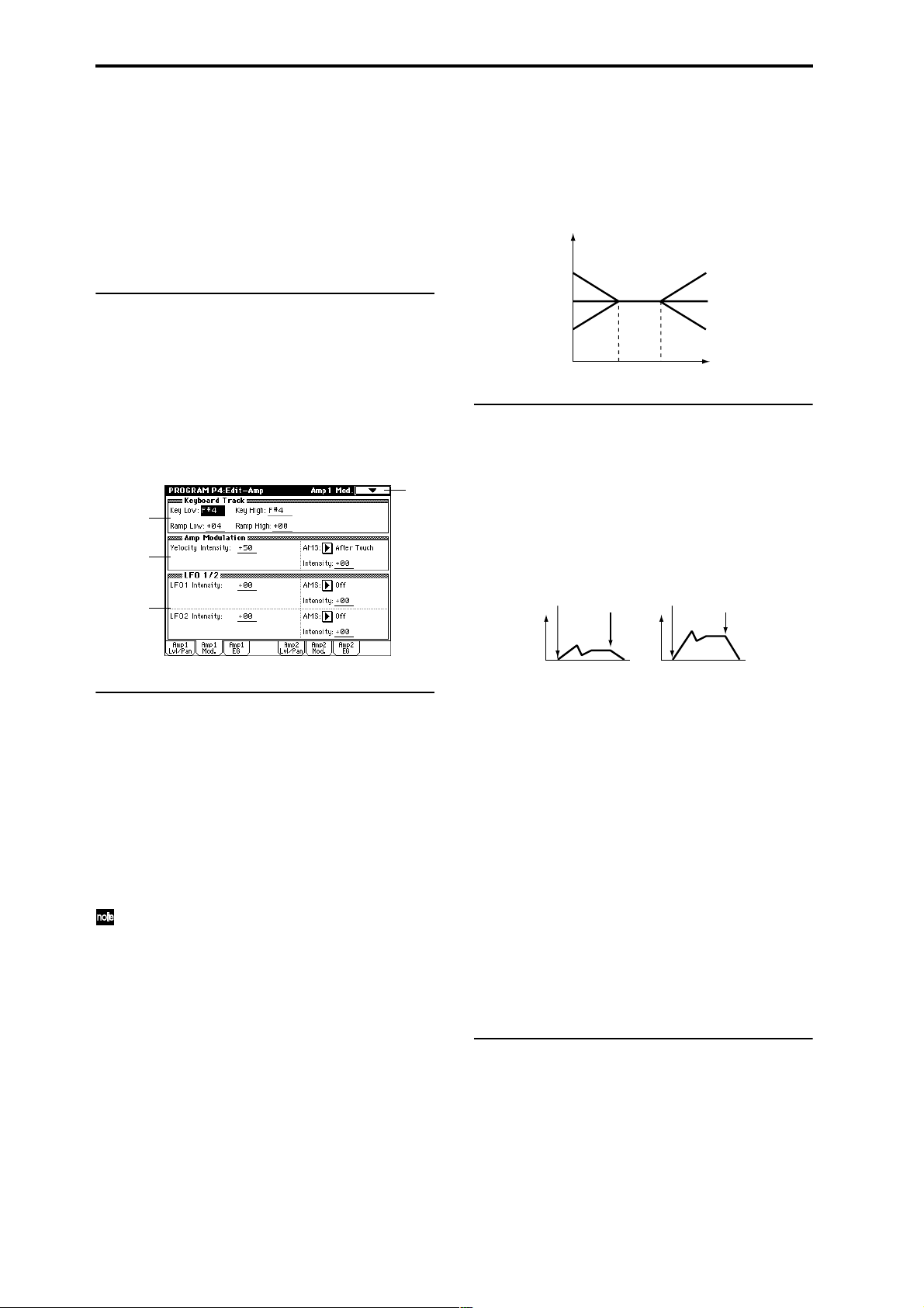
Intensity [–99…+99]
Specifies the depth of the effect produced by “AMS (Pan
AMS).”
For example if “Pan (Amp1 Pan)” is set to C064 and “AMS
(Pan AMS)” is Note Number, positive (+) values of this
parameter will cause the sound to move toward the right as
the note numbers increase beyond the C4 note (i.e., as you
play higher), and toward the left as the note numbers
decrease (i.e., as you play lower). Negative (–) values of this
parameter will have the opposite effect.
Ramp High (KBDTrk Ramp High) [–99…+99]
With positive (+) values of this parameter, the volume will
increase as you play notes above the “Key High (KBDTrk
Key High)” note number. With negative (–) values, the volume will decrease.
Volume change produced by keyboard location and Ramp settings
Volume
Ramp Low=+99
Ramp High=+99
▼ 4–1: Page Menu Command
☞ 0–1A: Write Program, 1–1A: Copy Oscillator, 1–1B: Swap
Oscillator
4–2: Amp1 Mod.
Applies modulation to amp 1 (for oscillator 1), make settings
for keyboard tracking to vary the volume, and set the intensity of velocity and LFO 1/2.
4–2
4–2a
4–2b
4–2c
4–2a: Keyboard Track
These parameters let you use keyboard tracking to adjust
the volume of oscillator 1. Use the “Key Low,” “Key High”
and “Ramp Low, ” “Ramp High” parameters to specify how
the volume will be affected by the keyboard location that
you play.
Key:
Specifies the note number at which keyboard tracking will
begin to apply.
The volume will not change between “Key Low (KBDTrk
Key Low)” and “Key High (KBDTrk Key High).”
The note number can also be input by holding the
[ENTER] key and playing a note on the keyboard.
Key Low (KBDTrk Key Low) [C–1…G9]
Keyboard tracking will apply to the range of notes below the
note number you specify here.
Key High (KBDTrk Key High) [C–1…G9]
Keyboard tracking will apply to the range of notes above the
note number you specify here.
Ramp:
Specifies the angle of the keyboard tracking.
Ramp Low (KBDTrk Ramp Low) [–99…+99]
With positive (+) values of this parameter, the volume will
increase as you play notes below the “Key Low (KBDTrk
Key Low)” note number. With negative (–) values, the volume will decrease.
Ramp Low=0
Ramp Low=–99
Key Low
Key High
Ramp High=0
Ramp High=–99
Key
4–2b: Amp Modulation
These parameters specify how the volume of oscillator 1 will
be affected by velocity.
Velocity Intensity [–99…+99]
With positive (+) values, the volume will increase as you
play with more velocity.
With negative (–) values, the volume will decrease as you
play with more velocity.
Volume change (with positive (+) values of this parameter)
Note-on
Softly played
Note-off
Note-on
Strongly played
Note-off
AMS (Amp AMS) [Off, (PEG, FEG, EXT)]
Selects the source that will control the volume of amp 1
(“AMS List” ☞p.242). (EXT) Velocity cannot be selected.
Intensity (AMS Intensity) [–99…+99]
Specifies the depth and direction of the effect that “AMS
(Amp AMS)” will have.
The actual volume will be determined by multiplying the
value of the changes produced by the amp EG with the values of Alternate Modulation etc., and if the levels of the amp
EG are low, the modulation applied by Alternate Modulation will also be less.
For example if “AMS (Amp AMS)” is set to After Touch,
positive (+) values of this parameter will cause the volume
to increase when pressure is applied to the keyboard. However if the EG settings etc. have already raised the volume to
its maximum level, the volume cannot be increased further.
With negative (–) values of this parameter, the volume will
decrease when pressure is applied to the keyboard.
4–2c: LFO 1/2
These parameters let you use “OSC1 LFO1” (5–1) and
“OSC1 LFO 2” (5–2) to control the oscillator 1 volume.
LFO1 Intensity [–99…+99]
Specifies the depth and direction of the effect that “OSC1
LFO1” will have on the volume of oscillator 1. Negative (–)
values will invert the LFO waveform.
22
Page 34
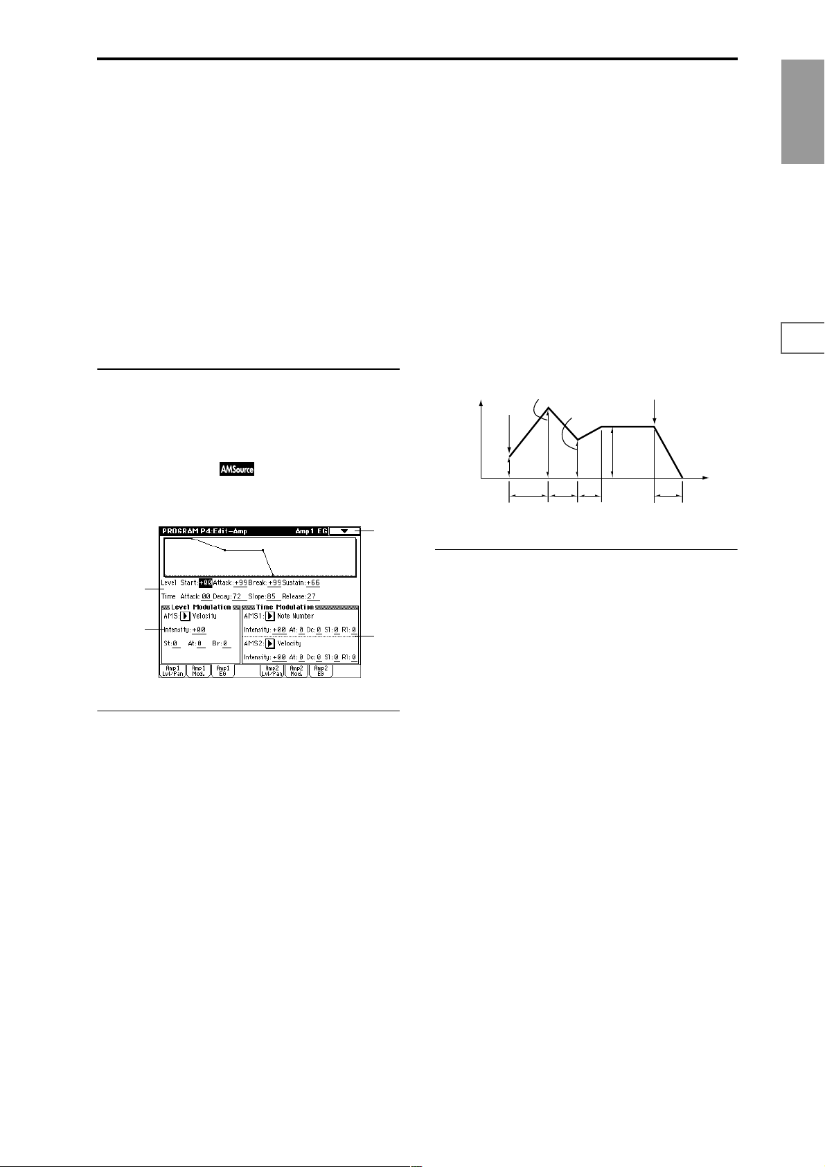
AMS (LFO1 AMS) [Off, (PEG, FEG, AEG, KT, EXT)]
Selects a source that will control the depth by which “OSC1
LFO1” will modulate the volume of oscillator 1 (“AMS List”
☞p.242).
Intensity (AMS Intensity) [–99…+99]
As the absolute value of this setting is increased, the effect of
“AMS (LFO1 AMS)” on “OSC1 LFO1” will increase. Nega-
tive (–) values will invert the LFO waveform.
LFO2 Intensity [–99…+99]
AMS (LFO2 AMS) [Off, (PEG, FEG, AEG, KT, EXT)]
Intensity (AMS Intensity) [–99…+99]
Specifies the depth and direction of the effect that “OSC1
LFO 2” (5–2) will have on the volume of oscillator 1. Refer to
the preceding sections “LFO1 Intensity”–“Intensity (AMS
Intensity).”
▼ 4–2: Page Menu Command
☞ 0–1A: Write Program, 1–1A: Copy Oscillator, 1–1B: Swap
Oscillator
4–3: Amp1 EG
These parameters let you create time-varying changes in the
volume of oscillator 1.
4–3
Time:
Attack (Attack Time) [00…99]
Specifies the time over which the volume will change after
note-on until it reaches the attack level.
If the start level is 0, this will be the rise time of the sound.
Decay (Decay Time) [00…99]
Specifies the time over which the volume will change from
when it reaches the attack level until it reaches the break
point level.
Slope (Slope Time) [00…99]
Specifies the time over which the volume will change from
when it reaches the break point level until it reaches the sustain level.
Release (Release Time) [00…99]
Specifies the time over which the volume will change after
note-off until it reaches 0.
Volume
Amplifier EG
Note-on
Attack Level
Start
Level
Attack
Time
Break Point
Decay
Time
Slope
Time
Sustain
Level
Note-off
Time
Release Time
Program
P0
P1 P2 P3 P4 P5 P7 P8 P9
4–3a
4–3b
4–3c
4–3a: Amp1 EG
These parameters specify how the amp 1 EG will change
over time.
Level:
Start (Start Level) [00…99]
Specifies the volume level at note-on.
If you want the note to begin at a loud level, set this to a high
value.
Attack (Attack Level) [00…99]
Specifies the volume level that will be reached after the
attack time has elapsed.
Break (Break Point Level) [00…99]
Specifies the volume level that will be reached after the
decay time has elapsed.
Sustain (Sustain Level) [00…99]
Specifies the volume level that will be maintained from after
the slope time has elapsed until note-off occurs.
4–3b: Level Modulation
Specifies how AMS will control the amp 1 EG level specified
in “Amp1 EG” (4–3a).
AMS (Level Mod.AMS) [Off, (KT, EXT)]
Selects the source that will control the Level parameters of
the amp 1 EG (“AMS List” ☞p.242).
Intensity (AMS Intensity) [–99…+99]
Specifies the depth and direction of the effect that “AMS
(Level Mod.AMS)” will have.
For example if “AMS (Level Mod.AMS)” is Velocity, setting
“St (AMS SW Start),” “At (AMS SW Attack),” and “Br (AMS
SW Break)” to + and setting “Intensity (AMS Intensity)” to a
positive (+) value will cause the amp 1 EG volume levels to
increase as you play more strongly. Setting “Intensity (AMS
Intensity)” to a negative (–) values will cause the amp 1 EG
volume levels to decrease as you play more strongly. With a
setting of 0, the levels will be as specified in “Amp1 EG” (4–
3a).
St (AMS SW Start) [–, 0, +]
Specifies the direction in which “AMS (Level Mod.AMS)”
will change “Start (Start Level).” If “Intensity (AMS Inten-
sity)” is set to a positive (+) value, setting this parameter to
+ will allow AMS to increase the EG level, and setting this
parameter to – will allow AMS to decrease the EG level.
With a setting of 0, no change will occur.
At (AMS SW Attack) [–, 0, +]
Specifies the direction in which “AMS (Level Mod.AMS)”
will change “Attack (Attack Level).” If “Intensity (AMS
Intensity)” is set to a positive (+) value, setting this parame-
ter to + will allow AMS to increase the EG level, and setting
this parameter to – will allow AMS to decrease the EG level.
With a setting of 0, no change will occur.
23
Page 35
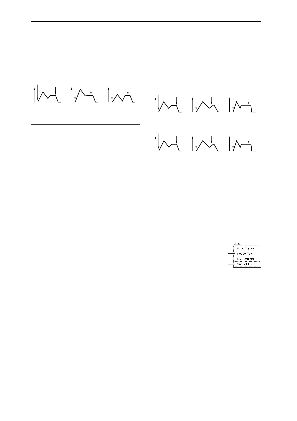
Br (AMS SW Break) [–, 0, +]
Specifies the direction in which “AMS (Level Mod.AMS)”
will change “Break (Break Point Level).” If “Intensity (AMS
Intensity)” is set to a positive (+) value, setting this parame-
ter to + will allow AMS to increase the EG level, and setting
this parameter to – will allow AMS to decrease the EG level.
With a setting of 0, no change will occur.
Amp 1 EG changes (Level) (AMS=Velocity, Intensity = a positive (+) value)
Note-on
Note-off
Note-on
Note-off
Note-on
Note-off
Rl (AMS1 SW Release) [–, 0, +]
Specifies the direction of the effect that “AMS1 (Time Mod.
AMS1)” will have on “Release (Release Time).” With posi-
tive (+) values of “Intensity (AMS1 Intensity),” setting this
parameter to + will allow AMS1 to lengthen the time, and
setting it to – will allow AMS1 to shorten the time. With a
setting of 0 there will be no effect.
Amp 1 EG changes (Time)
(AMS=Amp KTrk +/+, Intensity = a positive (+) value)
(When Amp Keyboard Track (4–2a) Low Ramp= a positive (+) value, and
High Ramp = a positive (+) value)
Note-on
Note-off
Note-on
Note-off
Note-on
Note-off
Softly played note when “St”=0
and “At” and “Br” are set to +
(settings of 4–3a: Amp 1 EG)
Strongly played note
when “St”=0 and “At” and
“Br” are set to +
Strongly played note
when “St”=0 and “At” and
“Br” are set to –
4–3c: Time Modulation
These parameters let you use an alternate modulation
source to modify the amp 1 EG times that were specified in
Amp1 EG (4–3a).
AMS1 (Time Mod. AMS1) [Off, (KT, EXT)]
Selects the source that will control the Time parameters of
the amp 1 EG (“AMS List” ☞p.242).
Intensity (AMS1 Intensity) [–99…+99]
Specifies the depth and direction of the effect that “AMS1
(Time Mod. AMS1)” will have.
For example if “AMS1 (Time Mod. AMS1)” is Amp KTrk +/
+, the (Amp) Keyboard Track settings (4–2a) will control the
EG Time parameters. With positive (+) values of this parameter, positive (+) values of Ramp will cause EG times to be
lengthened, and negative (–) values of Ramp will cause EG
times to be shortened. The direction of the change is speci-
fied by “At (AMS1 SW Attack),” “Dc (AMS1 SW Decay),”
“Sl (AMS1 SW Slope),” and “Rl (AMS1 SW Release).”
When “AMS1 (Time Mod. AMS1)” is Velocity, positive (+)
values will cause EG times to lengthen as you play more
strongly, and negative (–) values will cause EG times to
shorten as you play more strongly. With a setting of 0, the EG
times will be as specified in Amp1 EG (4–3a).
At (AMS1 SW Attack) [–, 0, +]
Specifies the direction of the effect that “AMS1 (Time Mod.
AMS1)” will have on “Attack (Attack Time).” With positive
(+) values of “Intensity (AMS1 Intensity),” setting this
parameter to + will allow AMS1 to lengthen the time, and
setting it to – will allow AMS1 to shorten the time. With a
setting of 0 there will be no effect.
Dc (AMS1 SW Decay) [–, 0, +]
Specifies the direction of the effect that “AMS1 (Time Mod.
AMS1)” will have on “Decay (Decay Time).” With positive
(+) values of “Intensity (AMS1 Intensity),” setting this
parameter to + will allow AMS1 to lengthen the time, and
setting it to – will allow AMS1 to shorten the time. With a
setting of 0 there will be no effect.
Sl (AMS1 SW Slope) [–, 0, +]
Specifies the direction of the effect that “AMS1 (Time Mod.
AMS1)” will have on “Slope (Slope Time).” With positive
(+) values of “Intensity (AMS1 Intensity),” setting this
parameter to + will allow AMS1 to lengthen the time, and
setting it to – will allow AMS1 to shorten the time. With a
setting of 0 there will be no effect.
Settings of 4–3a: Amp 1 EG
Amp 1 EG changes (Time) (AMS=Velocity, Intensity= a positive (+) value)
Note-on
Softly played note with “At,”
“Dc,” “Sl” and “Rl” at +
(settings of 4–3a: Amp 1 EG)
Note-off
Low-pitched note played with
“At,” “Dc,” “Sl,” and “Rl” at +
Note-on
Strongly played note with “At,”
“Dc,” “Sl” and “Rl” at +
Note-off
High-pitched note played with
“At,” “Dc,” “Sl,” and “Rl” at –
Note-on
Strongly played note with
“At,” “Dc,” “Sl” and “Rl” at –
Note-off
AMS2 (Time Mod. AMS2) [Off, (KT, EXT)]
Intensity (AMS2 Intensity) [–99…+99]
At (AMS2 SW Attack) [–, 0, +]
Dc (AMS2 SW Decay) [–, 0, +]
Sl (AMS2 SW Slope) [–, 0, +]
Rl (AMS2 SW Release) [–, 0, +]
These parameters specify how “AMS2 (Time Mod. AMS2)”
will control the amp 1 EG Time parameters (☞“AMS1 (Time
Mod. AMS1)”–“Rl (AMS1 SW Release)”).
▼ 4–3: Page Menu Command
0–1A
1–1A
1–1B
4–3A
4–3A: Sync Both EGs
When you select the page menu command “Sync Both
EGs,” a check mark will appear at the left of “Sync Both
EGs.” In this state, you can edit the amp 1 EG and amp 2 EG
simultaneously. (Editing either EG will change the settings
of both EGs.) (☞3–4A)
4–4: Amp2 Level/Pan 4–5: Amp2 Mod. 4–6: Amp2 EG
These are the parameters for amp 2 (used for oscillator 2).
(☞“4–1: Amp1 Level/Pan”–“4–3: Amp 1 EG.”)
These will appear when “Oscillator Mode” (1–1a) is Dou-
ble.
24
Page 36

Program P5: Edit–Common LFO
Here you can make settings for the LFO that can be used to
cyclically modulate the Pitch, Filter, and Amp of oscillators 1
and 2. There are two LFO units for each oscillator. By setting
the LFO1 or LFO2 Intensity to a negative (–) value for Pitch,
Filter, or Amp, you can invert the LFO waveform.
5–1: OSC1 LFO1
Make settings for the “OSC1 LFO1,” which is the first LFO
that can be used for oscillator 1.
Offset settings and pitch change produced by vibrato
offset = –99 offset = 0 offset = +99Pitch
Pitch at note-on
Key Sync. [Off, On]
On (checked): The LFO will start each time you press a key,
and an independent LFO will run for each note.
Off (unchecked): The LFO effect that started when the first
key was pressed will also apply to subsequently-played
notes. (In this case, the delay and fade effects will apply only
to the first-started LFO.)
Program
P0
P1 P2 P3 P4 P5 P7 P8 P9
5–1
5–1a
5–1b
5–1c
5–1a: OSC1 LFO1
Waveform [Triangle 0…Random6 (Vector)]
Selects the LFO waveform.
The numbers that appear at the right of some of the LFO
waveforms indicate the phase at which the waveform will
begin.
Triangle 0
Triangle 90
Triangle
Random
Saw 0
Saw 180
Square
Sine
Guitar
Exponential
Triangle
Exponential
Saw Down
Exponential
Saw Up
Triangle wave
Phase will change
randomly at each key-in
Sawtooth down ↓
Square wave
Sine wave
Guitar vibrato
Step Triangle – 4
Step Triangle – 6
Step Saw – 4
Step Saw – 6
Random1 (S/H):
Conventional sample & hold (S/H) in which the
level changes randomly at fixed intervals of
time
Random2 (S/H):
Both the levels and the time intervals will
change randomly.
Random3 (S/H):
The maximum level and minimum level will
alternate at random intervals of time (i.e., a
square wave with random period).
Random4 (Vect.)
Random5 (Vect.)
Random6 (Vect.)
These types cause Random 1–3 to change
smoothly. They can be used to simulate the
instability of acoustic instruments etc.
Frequency [00…99]
Sets the LFO frequency. A setting of 99 is the fastest.
Offset [–99…+99]
Specifies the central value of the LFO waveform.
For example with a setting of 0 as shown in the following
diagram, the vibrato that is applied will be centered on the
note-on pitch. With a setting of +99, the vibrato will only
raise the pitch above the note-on pitch, in the way in which
vibrato is applied on a guitar.
When “Waveform” is set to Guitar, the modulation will
occur only in the positive (+) direction even if you set “Off-
set” to 0.
Fade [00…99]
Specifies the time from when the LFO begins to apply until
it reaches the maximum amplitude. When “Key Sync.” is
Off, the fade will apply only when the LFO is first started.
How “Fade” affects the LFO (when “Key Sync.” is On)
Note-on Note-off
“Fade”
“Delay”
Delay [0…99]
Specifies the time from note-on until the LFO effect begins to
apply.
When “Key Sync.” is Off, the delay will apply only when
the LFO is first started.
5–1b: Frequency Modulation
You can use two alternate modulation sources to adjust the
speed of the OSC1 LFO1.
AMS1 (Freq. AMS1)
[Off, (PEG, FEG, AEG, LFO2, KT, EXT)]
Selects the source that will adjust the frequency of the oscillator 1 LFO1 (“AMS List” ☞p.242). OSC1 LFO1 can be modulated by OSC1 LFO2.
Intensity (AMS1 Intensity) [–99…+99]
Specifies the depth and direction of the effect that “AMS1
(Freq. AMS1)” will have.
When this parameter is set to a value of 16, 33, 49, 66, 82, or
99, the LFO frequency being can be increased by a maximum of 2, 4, 8, 16, 32, or 64 times respectively (or decreased
by 1/2, 1/4, 1/8, 1/16, 1/32, or 1/64 respectively).
For example if “AMS1 (Freq. AMS1)” is Note Number, pos-
itive (+) values of this parameter will cause the oscillator 1
LFO to speed up as you play higher notes. Negative (–) val-
ues will cause the oscillator 1 LFO to slow down as you play
higher notes. This change will be centered on the C4 note.
If “AMS1 (Freq. AMS1)” is set to JS +Y: CC#01, higher settings for this parameter will cause the OSC1 LFO speed to
become proportionately faster when you move the joystick.
With a setting of +99, the LFO speed will be approximately
64 times faster when the joystick is pushed all the way away
from yourself.
AMS2 (Freq. AMS2)
[Off, (PEG, FEG, AEG, LFO2, KT, EXT)]
Intensity (AMS2 Intensity) [–99…+99]
Make settings for a second alternate modulation source that
will adjust the frequency of the oscillator 1 LFO1. (☞“AMS1
(Freq. AMS1),” “Intensity (AMS1 Intensity)”)
25
Page 37

5–1c: Frequency MIDI/Tempo Sync.
MIDI/Tempo Sync. [Off, On]
On (checked): The LFO frequency will synchronize to the
tempo (MIDI Clock). In this case, the values you specified
for “Frequency” (5–1a) and Frequency Modulation (5–1b) will
be ignored.
Base Note (Sync. Base Note)
[ , , , , , , , ]
Times (Sync. Times) [01...16]
When “MIDI/Tempo Sync.” is checked, these parameters
set a note length relative to “ (Tempo)” and the multiple
(“Times”) that will be applied to it. These parameters will
determine the frequency of the OSC1 LFO1. For example if
“Base Note (Sync. Base Note)” is (quarter note) and “Times
(Sync. Times)” is 04, the LFO will perform one cycle every
four beats.
Even if you change the “ (Tempo)” setting of the arpeggiator or sequencer, the LFO will always perform one cycle
every four beats.
▼ 5–1: Page Menu Command
0–1A
5–1A
5–1A: Swap LFO 1&2
This command exchanges the settings of LFO1 and 2. If
LFO2 has been selected as Frequency Modulation “AMS1
(Freq. AMS1)”or “AMS2 (Freq. AMS2)” (5–1b) of LFO1, that
setting will be cancelled for LFO2 after the LFO1 and 2 settings have been exchanged. If this is selected from the OSC1
LFO1 or OSC1 LFO2 page, the LFO1 and LFO2 of OSC1 will
be exchanged.
1 Select “Swap LFO 1&2” to access the dialog box.
5–4: OSC2 LFO2
This can be used when “Oscillator Mode” (1–1a) is set to
Double.
Here you can make settings for the OSC2 LFO2, which is the
second LFO that can be applied to oscillator 2 (☞“5–1: OSC1
LFO1” and “5–2: OSC1 LFO2”).
Program P7: Edit–Arpeggiator
Here you can make settings for the arpeggiator used by the
program.
You can make settings so that when you select a program,
these arpeggiator settings will automatically switch to the
arpeggiator settings that are memorized in the selected program. (Global P0: 0–1c Auto Arpeggiator “Program”)
The arpeggiator can be switched on/off by the ARPEGGIATOR [ON/OFF] key. When on, the key LED will light.
The settings of the ARPEGGIATOR [TEMPO] knob, [GATE]
knob, [VELOCITY] knob, and [ON/OFF] key can be saved
for each program.
These settings will be valid when “Auto Arpeggiator”
Program is checked.
You can control the arpeggiator from an external
sequencer, or record note data generated by the arpeggiator onto an external sequencer. (☞p.266)
“Pattern,” “Resolution,” “Octave,” “Sort,” “Latch,”
“Key Sync.,” “Keyboard,” and “ (Tempo)” can also be
set from the P0: Play, Arpeggio page.
7–1: Arpeg. Setup
7–1
7–1a
2 Press the OK button to execute, or press the Cancel but-
ton to cancel without executing.
5–2: OSC1 LFO2
Here you can make settings for the OSC1 LFO2, which is the
second LFO that can be applied to oscillator 1. (☞“5–1:
OSC1 LFO1”) However in “Frequency Modulation” (5–1b),
the LFO cannot be selected as a modulation source in
“AMS1 (Freq. AMS1)”or “AMS2 (Freq. AMS2).”
5–3: OSC2 LFO1
This can be used when “Oscillator Mode” (1–1a) is set to
Double.
Here you can make settings for the OSC2 LFO1, which is the
first LFO that can be applied to oscillator 2 (☞“5–1: OSC1
LFO1”).
26
7–1b
7–1a: Arpeggiator Tempo
(Tempo)* [040...240, EXT]
Sets the tempo.
This can also be set by the [ARPEGGIATOR TEMPO] knob.
When “MIDI Clock” (Global P1: 1–1a) is set to either Exter-
nal MIDI or External mLAN, this parameter will indicate
EXT, and the arpeggiator will synchronize to the MIDI
Clock received from an external MIDI device.
Page 38
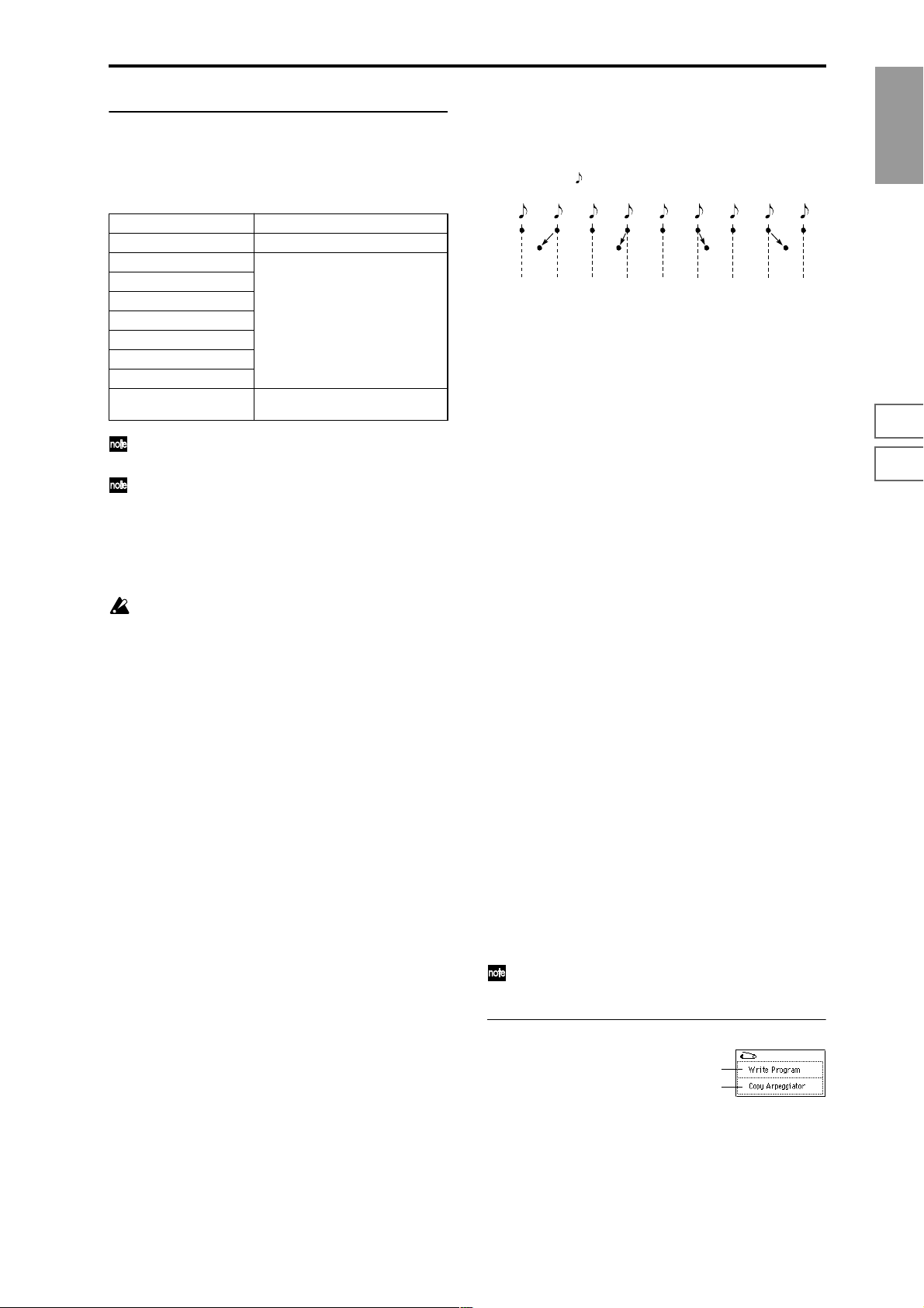
7–1b: Arpeggiator Setup
☞ Refer to BG p.130.
Pattern* [P00...P04, U000(I-A/B)...U506(User)]
Selects the arpeggio pattern.
P00...P04 Preset arpeggio patterns
U000(I-A/B)...U199(I-A/B) Preloaded arpeggio patterns
U200(E-A)...U215(E-A)
U216(E-B)...U231(E-B)
U232(E-C)...U247(E-C)
U248(E-D)...U263(E-D)
U264(E-E)...U279(E-E)
U280(E-F)...U295(E-F)
U296(E-G)...U311(E-G)
U312(User)...U506(User) User arpeggio patterns
EXB-PCM series
(user arpeggio patterns)
(some preloaded arpeggio patterns)
U000 (I–A/B)–U506 (User) are rewritable. Use Global
P6 to create arpeggio patterns.
Arpeggio patterns U000 (I-A/B)–U506 (User) can be
selected using the numeric keys [0]–[9] and the
[ENTER] key.
Octave* [1, 2, 3, 4]
Specifies the number of octaves in which the arpeggio will
be played.
If a user arpeggio pattern is selected, the range of the
arpeggio will depend on the “Octave Motion” (Global
P6: 6–1b) setting.
Resolution* [ , , , , , ]
Specifies the timing resolution of the arpeggio. The notes of
the arpeggio will be played at the interval you specify: ,
, , , , or . The speed of the arpeggio pattern is
determined by the “Arpeggiator Tempo ” and the “Resolution.”
Gate [000...100(%), Step]
Specifies the length (gate time) of each note in the arpeggio.
000–100(%): Each note will be played with the specified gate
time.
Step: This is available when an user arpeggio pattern U000
(I-A/B)–U506 (User) is selected for “Pattern.” When this is
selected, the gate time specified for each step will be used.
The gate time can also be controlled by the ARPEGGIATOR
[GATE] knob. Rotating the knob towar d the left will shorten
the gate time, and rotating it toward the right will lengthen
the gate time. When the knob is at the 12 o’clock position,
the gate time will be as specified here.
Velocity [001...127, Key, Step]
Specifies the velocity of the notes in the arpeggio.
001–127: Each note will sound with the specified velocity
value.
Key: Each note will sound with the velocity value at which
it was actually played.
Step: This is available when an user arpeggio pattern U000
(I-A/B)–U506 (User) is selected for “Pattern.” When this is
selected, the velocity specified for each step will be used.
The velocity can also be controlled by the ARPEGGIATOR
[VELOCITY] knob. Rotating the knob toward the left will
decrease the velocity, and rotating it toward the right will
increase the velocity. When the knob is at the 12 o’clock position, the velocity will be as specified here.
Swing [–100...+100(%)]
This parameter shifts the timing of the odd-numbered notes
of the arpeggio.
When Resolution =
Step
123456789
–50 –25 +25 +50
Swing
Sort* [Off, On]
This specifies the order in which the notes you press will be
arpeggiated.
On (checked): Notes will be arpeggiated in the order of
their pitch, regardless of the order in which you pressed
them.
Off (unchecked): Notes will be arpeggiated in the order in
which you pressed them.
Latch* [Off, On]
Specifies whether or not the arpeggio will continue playing
after you take your hand off of the keyboard.
On (checked): The arpeggio will continue playing after you
remove your hand from the keyboard.
Off (unchecked): The arpeggio will stop when you remove
your hand from the keyboard.
Key Sync.* [Off, On]
Specifies whether the arpeggio pattern will begin when you
press a key, or whether it will always follow the “ (Tempo)”
(0–1a).
On (checked): The arpeggio pattern will start playing from
the beginning when a note-on occurs from a condition
where no keys are pressed. This setting is suitable when you
are playing in realtime and want the arpeggio to play from
the beginning of the measure.
Off (unchecked): The arpeggio pattern will always play
according to the “ (Tempo).”
Keyboard* [Off, On]
This specifies whether the notes you play on the keyboard
will be sounded as usual in addition to being sounded as
part of the arpeggio (“keyboard” 0–2a).
On (checked): The notes you play will be sounded on their
own, in addition to being sounded as part of the arpeggio.
For example if you simultaneously press two or more notes,
they will be sounded as usual in addition to being played as
arpeggiated notes.
Off (unchecked): Only the arpeggiated notes will be heard.
*: These parameters can also be set from “P0: Play,
Arpeggio.”
▼ 7–1: Page Menu Command
0–1A
7–1A
7–1A: Copy Arpeggiator
This command can be used to copy arpeggio settings from
another location to the current program.
Program
P0
P1 P2 P3 P4 P5 P7 P8 P9
27
Page 39
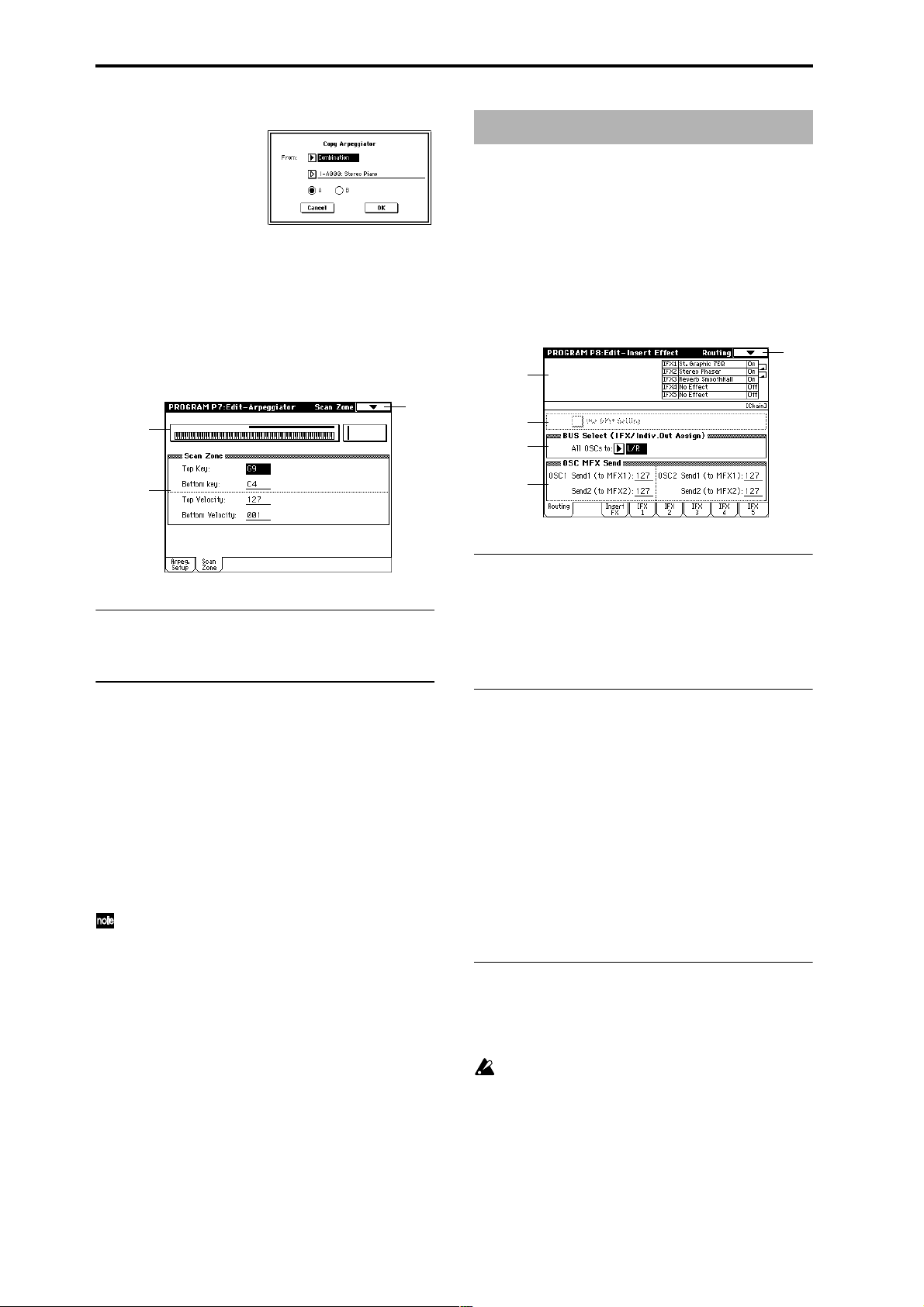
1 Select “Copy Arpeggiator” to access the dialog box.
Program P8: Edit–Insert Effect
☞ For details on insertion effects, refer to p.178 “8. Effect
Guide.”
2 In “From” specify the source of the arpeggio settings
(mode, bank, number) that you wish to copy.
3 If you are copying from Combination, Song, or Song Play
mode, specify whether you wish to copy from A or B.
4 To execute the Copy Arpeggio operation, press the OK
button. To cancel, press the Cancel button.
7–2: Scan Zone
7–1
7–2a
7–2b
7–2a: Zone Map
This shows the Scan Zone setting.
8–1: Routing
These settings specify the bus on which the output of the
oscillator will be sent, and can be used to adjust the send
levels to the master effects.
The following diagram shows the LCD screen when “Oscil-
lator Mode” (1–1a) is set to Double.
8–1
8–1a
8–1b
8–1c
8–1d
8–1a: Routing Map
This shows the status of the insert effects.
The insert effect routing, effect name, on/off status, and
chain is shown. The types of insert effect, on/off, and chain
settings are made in the P8: Edit-Insert Effect, Insert FX
page.
7–2b: Scan Zone
Top Key [C–1...G9]
Bottom Key [C–1...G9]
These parameters specify the range of notes (keys) for which
the arpeggiator will function. “Top Key” is the upper limit,
and “Bottom Key” is the lower limit.
Top Velocity [001...127]
Bottom Velocity [001...127]
Specifies the range of velocities for which the arpeggiator
will function. “T op Velocity” is the upper limit, and “Bottom
Velocity” is the lower limit.
Note number and velocity can also be entered by holding down the [ENTER] key and playing a note on the
keyboard.
8–1b: Use DKit Setting
Use DKit Setting [Off, On]
This will be available only when “Oscillator Mode” (1–1a)
is set to Drums.
On (checked): The “BUS Select” (Global P5: 5–2a) setting for
each key of the selected drum kit will be used. Check this
when you want to apply an insert effect to an individual
drum instrument, or to output an individual drum instrument to one of the AUDIO OUTPUT (INDIVIDUAL) jacks.
If the “Oscillator Mode” is Single or Double, this setting has
no effect.
Off (unchecked): The setting of the BUS Select (8–1c), OSC
MFX Send (8–1d) parameter described below will be used.
All drum instruments will be sent to the specified bus.
8–1c: BUS Select (IFX/Indiv.Out Assign)
BUS Select (All OSCs to)
[L/R, IFX1...5, 1...4, 1/2, 3/4, Off]
Specifies the bus to which oscillators 1 and 2 will be sent.
If this is set to 1/2 or 3/4, the oscillator pan settings (4–
1b, 4–4) will be used to output the sound in stereo from
AUDIO OUTPUT (INDIVIDUAL) 1/2 or 3/4. When
the oscillator pan is controlled by CC#10 (pan) or AMS
(Pan AMS), the sound will be output with the pan setting that is in effect at note-on. Unlike the case when
this is set to L/R to output the sound from (MAIN) L/
MONO and R, the pan of a sounding note will not
change in realtime.
28
Page 40
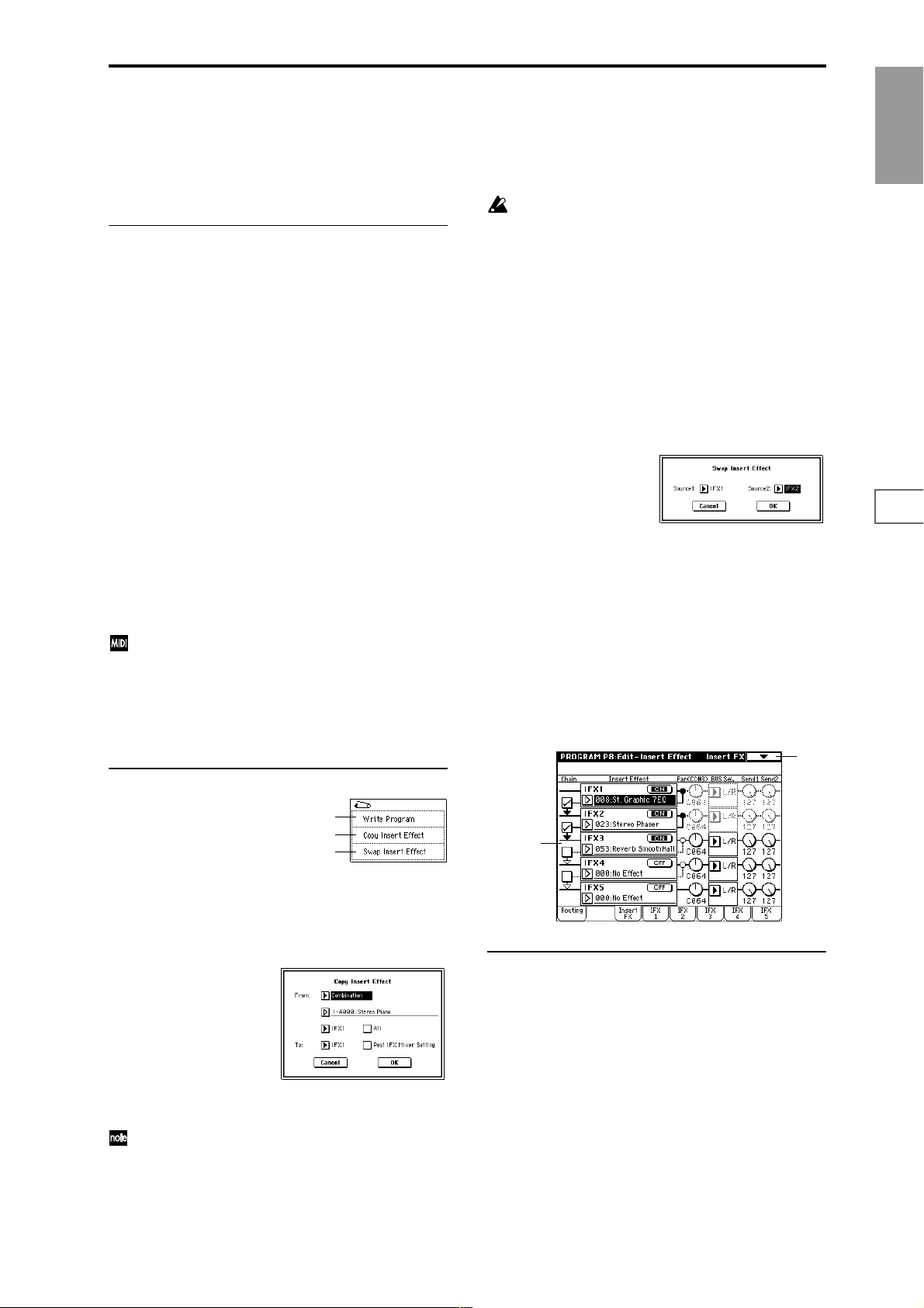
If you wish to adjust the pan in realtime during a note
and output the sound from AUDIO OUTPUT (INDIVIDUAL) 1/2 or 3/4, set “BUS Select ” to IFX1 (or
IFX2–IFX5), set “IFX1” (or IFX2–IFX5) to 000: No
Effect, and set the “BUS Sel. (BUS Select)” (8–2a) after
passing through IFX to 1/2 or 3/4.
8–1d: OSC MFX Send
OSC1:
Send1 (to MFX1) [000...127]
Sets the volume (send level) at which the output of oscillator
1 will be sent to master effect 1. This is valid when “BUS
Select” (8–1c) is set to L/R or Off.
If “BUS Select” is set to IFX1, IFX2, IFX3, IFX4 or IFX5, the
send levels to master effect 1 and 2 are set by “Send 1” and
“Send 2” (8–2a) after passing through IFX 1/2/3/4/5 of the
Insert FX pages.
Send2 (to MFX2) [000...127]
Sets the volume (send level) at which the output of oscillator
1 will be sent to master effect 2 (☞“Send 1 (to MFX1)”).
OSC2:
3 Select which of the effects you wish to copy.
You can also copy from a master effect. If “All” is
checked, all effect settings will be copied (i.e., the con-
tents of the Insert FX page and the effect parameters of
IFX 1–5, but not “Ctrl Ch”).
If you are copying from a master effect, the result may
not be identical, due to differences in the routing and
level settings of a master effect.
4 Select the insert effect copy destination.
If you check “Post IFX Mixer Setting,” the “Chain,”
“Pan (CC#8),” “BUS Sel.,” “Send 1” and “Send 2” set-
tings that follow the copy source insert effect will also be
copied. If this is unchecked, only the effect type and its
parameters will be copied.
5 To execute the Copy Insert Effect command, press the
OK button. To cancel, press the Cancel button.
8–1B: Swap Insert Effect
This command swaps (exchanges) insert effect settings.
1 Select “Swap Insert Effect” to access the dialog box.
Program
P0
P1 P2 P3 P4 P5 P7 P8 P9
Send1 (to MFX1) [000...127]
Send2 (to MFX2) [000...127]
Sets the volume (send level) at which the output of OSC2
will be sent to master effects 1 and 2. These parameters will
be valid when “Oscillator Mode” (1–1a) is set to Double
and “BUS Select” is set to L/R or Off.
CC#93 will control the Send 1 level for OSC 1/2, and
control change CC#91 will control the Send 2 level for
OSC 1/2. These are controlled on the global MIDI channel “MIDI Channel” (Global P1: 1–1a).
The actual send level is determined by multiplying
these values with the send level setting of each oscillator.
▼ 8–1: Page Menu Command
0–1A
8–1A
8–1B
8–1A: Copy Insert Effect
This command copies effect settings from Program, Combination, Song, Sampling mode, or Song Play mode.
1 Select “Copy Insert Effect” to access the dialog box.
2 In “Source 1” and “Source 2,” select each of the insert
effects that you wish to swap.
3 To execute the Swap Insert Effect command, press the
OK button. To cancel, press the Cancel button.
8–2: Insert FX
Here you can select the type of each insert effect, turn it on/
off, and make chain settings.
The direct sound (Dry) of an insert effect is always stereo
input and output. The input/output of the effect sound
(Wet) will depend on the effect type (☞p.178).
8–1
8–2a
8–2a: IFX1, 2, 3, 4, 5
2 In “From” select the source mode, bank, and number of
the effect to be copied.
You can select a bank by pressing the [INT-A]–[EXB-G]
keys.
IFX1, 5 [000...089]
IFX2, 3, 4 [000...102]
Selects the type of each insert effect.
For “IFX1” and “IFX5” you can select from 90 types of effect:
000: No Effect – 089: Reverb-Gate. Double-size effects cannot be used.
For “IFX2,” “IFX3” and “IFX4” you can select from 103
types of effect: 000: No Effect – 102: Hold Delay.
If you select a double-size effect, the insert effect that follows
will be unavailable. For example if you select a double-size
effect for “IFX2,” “IFX3” cannot be used. Up to two doublesize effects can be used. (You can use a normal size effect for
“IFX1,” and double-size effects for “IFX2” and “IFX4.”)
(☞p.178)
29
Page 41
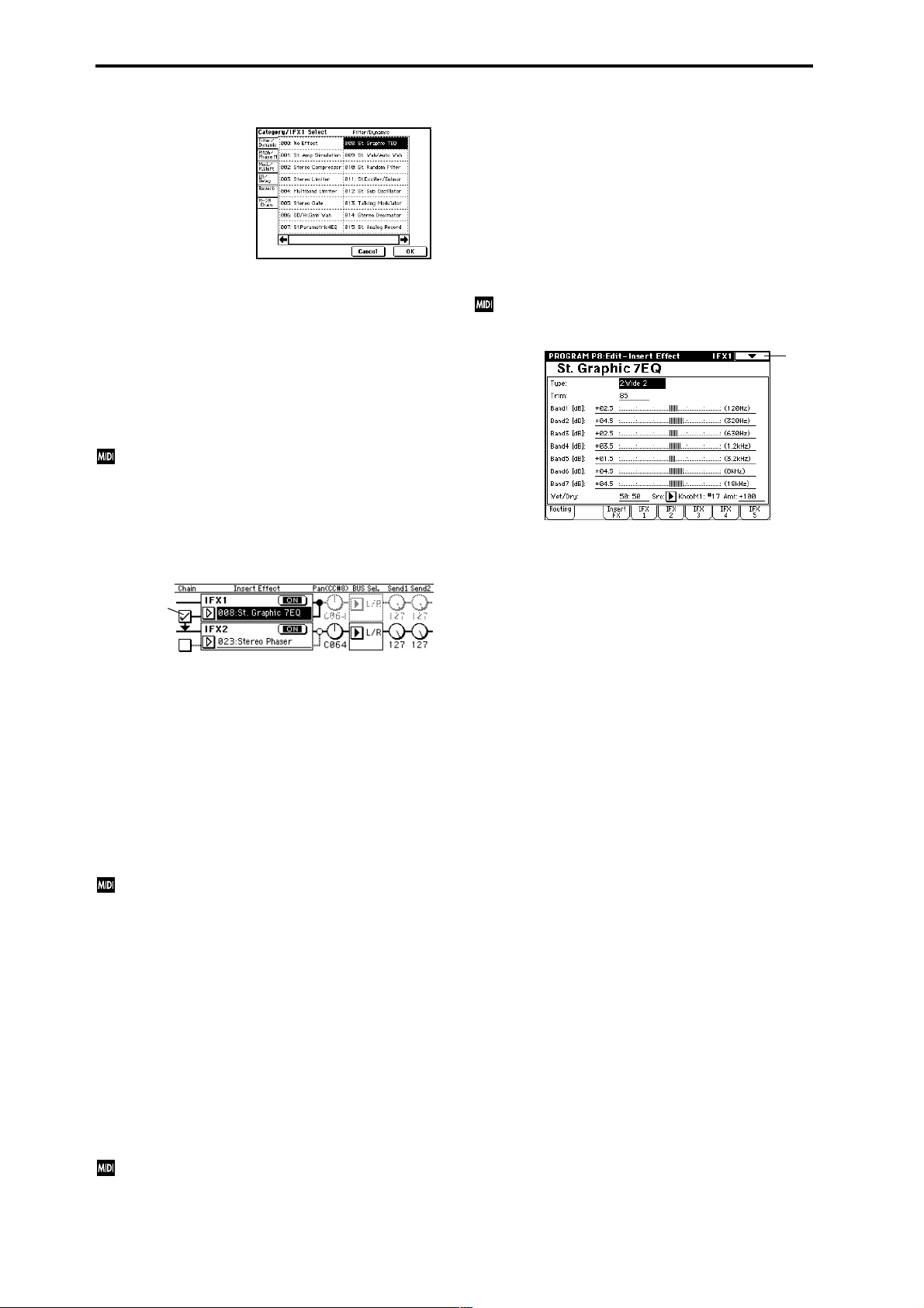
Category/IFX Select menu:
When you press the popup button, a “Category/IFX Select”
list will appear. Pr ess a tab to select a category of effects, and
select an effect from that category. Press the OK button to
execute, or press the Cancel button to cancel.
IFX1, 2, 3, 4, 5 On/Off [Off, ON]
Switches the insert effect on/off.
When this is OFF, the input will be output unchanged. (For
000: No Effect, on/off will produce the same result.)
Each time you press this, the setting will alternate between
on/off.
Control change #CC92 can be used to turn off all of the
insert effects at once. A value of 0 will be off, and a
value of 1–127 will be the original setting. This message
is received on the global MIDI channel specified by
“MIDI Channel” (Global P1: 1–1a).
8–3: IFX 1 8–4: IFX 2 8–5: IFX 3 8–6: IFX 4 8–7: IFX 5
Here you can set the effect parameters for the IFX 1/2/3/4/
5 that were selected in the Insert FX page (☞p.187–).
Effect dynamic modulation (Dmod) is controlled on the
global MIDI channel “MIDI Channel” (Global P1: 1–1a).
(“D.mod” ☞p.247)
0–1
Chain [Off, On]
Switch “chain” on/off for each insert effect.
Chain
For example if the “Chain” check box between IFX1 and
IFX2 is checked, IFX1 and IFX2 will be connected in series. If
“BUS Select” (8–1c) is set to IFX1, IFX1 and IFX2 will be
inserted in series.
A maximum of five insert effects (IFX1–IFX5) can be
inserted in series. When effects are chained, the “PAN
(CC#8),” “BUS Select,” “Send 1” and “Send 2” settings that
follow the last IFX in the chain will be used.
Pan(CC#8) (Post IFX PanCC#8) [L000...C064...R127]
Sets the pan after the sound has passed through the insert
effect. This setting is valid only when the following “BUS
Select” is set to L/R (☞p.181).
CC#8 will control the pan of the sound after it has
passed through the insert effect.
BUS Sel. (BUS Select) [L/R, 1, 2, 3, 4, 1/2, 3/4, Off]
Specifies the bus to which the sound will be sent after passing through the insert effect. Normally you will set this to L/
R. If you wish to output to AUDIO OUTPUT (INDIVIDUAL), set this to 1, 2, 3, 4, 1/2, or 3/4. The Off setting is used
when you wish to use “Send 1” and “Send 2” and in addition connect to the master effects in series.
Send1 [000...127]
Send2 [000...127]
Sets the send levels to the master effects 1 and 2 for the
sound that has passed through the insert effect. These settings are valid when “BUS Select” (8–2a) has been set to L/R
or Off.
Control change CC#93 will control the Send 1 level, and
control change CC#91 will control the Send 2 level.
These messages are received on the global MIDI channel specified by “MIDI Channel” (Global P1: 1–1a).
30
Page 42

Program P9: Edit–Master Effect
☞ For details on the master effects, refer to p.182 “8. Effect
Guide.”
9–1: Master FX
Here you can select the master effect types, switch them on/
off, specify chain order, and set the master EQ.
9–1
9–1a
9–1c
9–1b
9–1a: MFX1, 2
The master effects do not output the direct sound (Dry). The
return level (“Return1,” “Return2”) sends the effect sound
(Wet) to the L and R bus, and this is mixed with the direct
sound (i.e., the output from P8: Routing tab “BUS Select” L/
R, or the L/R output from Insert FX page “BUS Select”).
The master effects have a mono input. After passing through
the oscillator and insert effects, sound that is panned L and
R is mixed to a mono signal (as adjusted by the “Send 1” and
“Send 2” levels) and input to the master effects.
The master effects are mono-in stereo-out. Even when
a stereo-input type effect is selected, the input will be
monaural.
MFX1, 2 [000...089]
Selects the effect type for master effect 1 and 2. You can
select from 90 types of effect: 000: No Effect–089: Reverb-
Gate. (Double-size effects cannot be selected.) If 000: No
Effect is selected, the output from the master effect will be
muted.
Category/MFX Select menu:
When you press the popup button, a “Category/MFX
Select” menu will appear. Press a tab to select the desired
category of effect, and select an effect from the list. Press the
OK button to execute, or press the Cancel button to cancel.
MFX1, 2 On/Off [Off, ON]
Switches the master effects 1, 2 on/off. When off, the output
will be muted. This will alternate between on and off each
time it is pressed.
CC#94 can be used to switch the MFX on and off. A
value of 0 will be off, and a value of 1–127 will be the
original setting. This is controlled on the global MIDI
channel “MIDI Channel” (Global P1: 1–1a).
Chain [Off, On]
On (checked): Chain (series connection) will be turned on
for MFX1 and MFX2.
Off (unchecked): MFX1 and MFX2 will operate in parallel.
Chain Direction [MFX1→MFX2, MFX2→MFX1]
Specifies the direction of the connection when MFX1 and
MFX2 are chained.
MFX1→MFX2: Connect from MFX1 to MFX2.
MFX2→MFX1: Connect from MFX2 to MFX1.
Chain Signal [LR Mix, L Only, R Only]
When chain is On, this parameter specifies how the stereo
output signal of the first master effect will be connected to
the input (mono) of the next master effect.
L/R Mix: The stereo output L/R of the first master effect will
be mixed before being input to the next master effect.
L Only, R Only: Only the left or right channel of the output
will be input to the next master effect.
Chain Level [000...127]
When chain is On, this sets the level at which the sound is
sent from the first master effect to the next master effect.
9–1b: Return Level
Return 1, 2 [000...127]
Adjusts the return levels from the master effects to the L/R
bus (main output L/MONO, R).
9–1c: Master EQ Gain [dB]
Sets the gain for the three-band EQ located immediately
before the sound of the L/R bus is sent from the AUDIO
OUTPUT (MAIN OUT) L/MONO and R jacks. This is
linked with the various “Gain” parameters of Master EQ (9–
4).
Low [–18.0...+18.0]
Mid [–18.0...+18.0]
High [–18.0...+18.0]
The cutoff frequency for “Low,” “Mid” and “High” and the
“Q” of “Mid” can be adjusted in the Master EQ page. These
settings are in “dB” units.
Program
P0
P1 P2 P3 P4 P5 P7 P8 P9
31
Page 43

▼ 9–1: Page Menu Command
0–1A
9–1A
9–1B
9–1A: Copy Master Effect
This command lets you copy any desired effect settings from
Program, Combination, Song, Sampling, or Song Play mode.
1 Select “Copy Master Effect” to access the dialog box.
2 In “From,” select the copy source mode, bank, and num-
ber.
3 Select the effect that you want to copy.
If you select MFX1 or MFX2, “Return” (return level) will
be copied at the same time.
If you select Master EQ, only the master EQ settings will
be copied.
You can select from an insert effect by selecting IFX 1–5.
If you check “All,” all settings for the master effects and
master EQ will be copied.
If you are copying from an insert effect, differences in
routing and level will mean that the result will not be
completely identical.
4 In “To,” specify the copy destination master effects.
5 To execute the Copy Master Effect command, press the
OK button. To cancel, press the Cancel button.
9–2: MFX 1 9–3: MFX 2
Makes effect parameter settings for the MFX1 and 2 effects
that were selected in the Master FX page (9–2). (☞p.187–)
Effect dynamic modulation (Dmod) is controlled on the
global MIDI channel “MIDI Channel” (Global P1: 1–1a).
(“D.mod” ☞p.247)
0–1
9–4: Master EQ
The master EQ is a three-band stereo EQ. It is used to adjust
the overall tonality of the sound immediately before the L/R
bus is output to the AUDIO OUTPUT (MAIN OUT) L/
MONO and R jacks (☞p.239).
0–1
9–1B: Swap Master Effect
This command swaps (exchanges) the settings of MFX1 and
MFX2.
1 Select “Swap Master Effect” to access the dialog box.
2 To execute the Swap Master Effect command, press the
OK button. To cancel, press the Cancel button.
The MEQ High Gain and MEQ Low gain can be controlled
by assigning a modulation source to the “Low Gain ModSrc:” and the “High Gain Mod-Src:” functions on this page.
32
Page 44
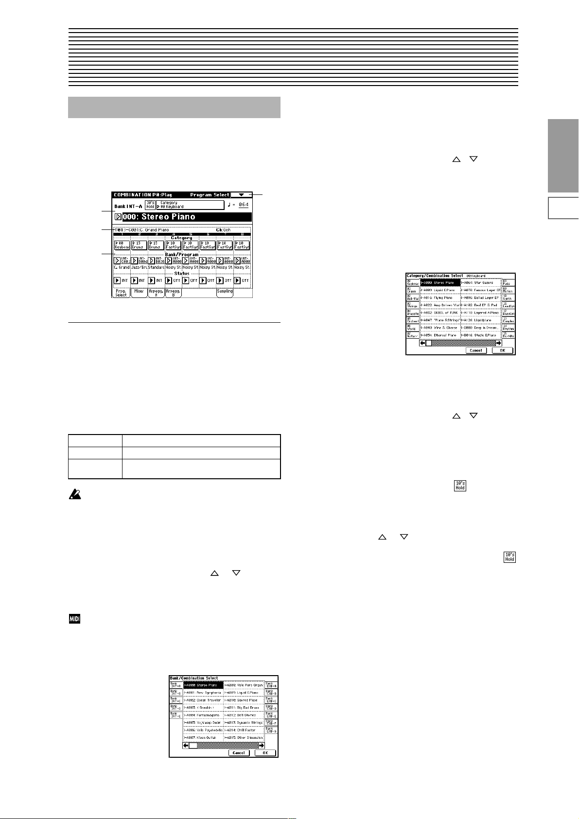
2. Combination mode
Combination P0: Play
In this display page you can select and play Combinations.
A Combi allows you to use up to eight programs at once.
0–1: Prog. Select (Program Select)
0–1
0–1a
0–1b
0–1c
0–1a: Bank, Combination Select, 10’s Hold,
Category,
1 Press the popup button located at the left of “Combina-
tion Select” to access the Bank/Combination Select
menu.
2 Press one of the tabs located at the left or right to select a
bank.
3 Select a combination from the list. You can directly press
your choice within the list, or use the [] [] keys.
4 Press the OK button to execute, or press the Cancel but-
ton to cancel your selection.
Category [00...15]
Select the combination category.
Each combination is assigned to one of 16 categories. You
can choose a category, and select from the combinations
included in that category. When you press the popup menu
button, the Category/Combination Select menu will appear.
Category/Combination Select menu:
Combination
P0
P1 P2 P3 P4 P7 P8 P9
Bank (Bank Select)[Bank INT-A…INT-E, EXB-A...EXB-G]
This is the Combination bank display.
Press one of the BANK [INT-A]–[EXB-G] keys to select a
bank.
Each of the rewritable banks INT-A–INT-E and EXB-A–
EXB-G contain 128 (a total of 1,536) combination program
areas.
INT-A...INT-D Preloaded combinations
INT-E User combinations, EXB-MOSS combinations
EXB-A...EXB-G User combinations, EXB-PCM series combina-
tions
If you have selected the “Bank/Program (Program
Select)” (0–1d) edit cell for a timbre 1–8 in the Prog.
Select page, BANK [INT-A]–[EXB-G] will switch the
program banks for timbres 1–8.
Combination Select [0…127]
Here you can select the desired combination. When this
parameter is selected, you can select combinations using the
numeric keys [0]–[9], [VALUE] dial, or [ ], [ ] keys.
When you press the popup button, the Bank/Combination
Select menu will appear. Here you can select combinations
by bank.
You can select combinations by transmitting MIDI program changes from a connected external MIDI device,
or by using a foot switch. (“Foot SW Assign” Global P2:
2–1a, “Foot Switch Assign List” ☞p.251)
Bank/Combination Select menu:
1 Press the (category) popup button located at the top of
“Combination Select” to access the Category/Combination Select menu.
2 Press one of the tabs at left or right to select a category.
3 Select a combination from the list. You can directly press
your choice within the list, or use the [] [] keys.
4 Press the OK button to execute, or press the Cancel but-
ton to cancel your selection.
The category of each combination can be specified in the
“Write Combination” (0–1A) dialog box.
10’s Hold
1 Press the [./10’s HOLD] key to display .
The 10’s place of the combination number will be held
(fixed).
2 Press any numeric key [0]–[9] to input the 1’s place of the
combination number with a single keystroke.
3 You can use the [ ], [ ] keys to change the value of
the 10’s place.
4 To cancel, press the [./10’s HOLD] key to turn off the
display.
(Tempo) [040...240, EXT]
This sets the tempo of the arpeggiator. The tempo can also
be adjusted by the ARPEGGIATOR [TEMPO] knob. A display of EXT indicates that the “MIDI Clock” setting (Global
P1: 1–1a) has been set to External MIDI or External mLAN,
and that the arpeggiator will synchronize to MIDI Clock
messages received from an external MIDI device.
33
Page 45
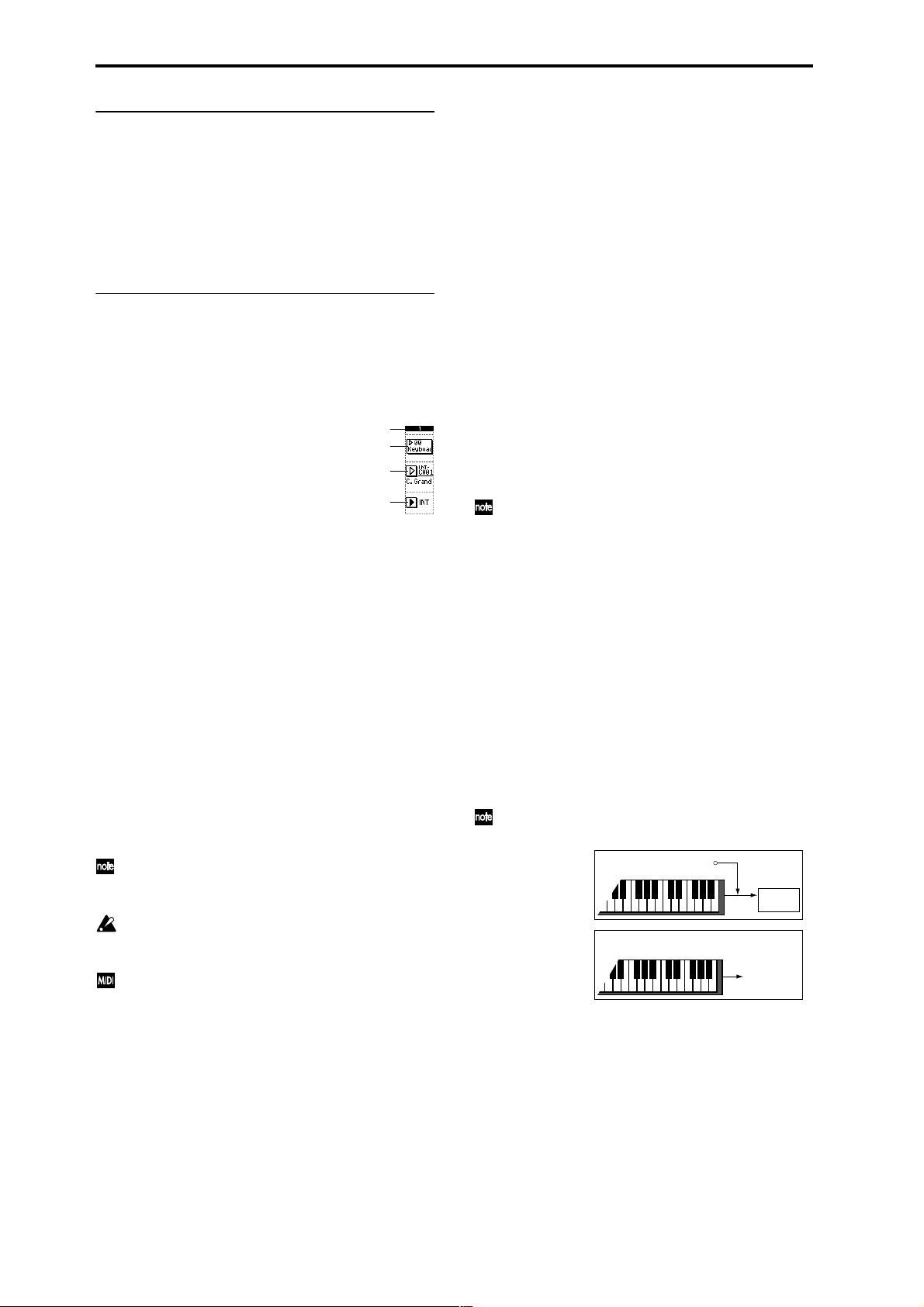
0–1b: Selected Timbre Information
This displays information on the selected timbre (1–8).
T (Timbre) [01...08]
Indicates the timbre number and the bank/number/name
of the program that is selected for the timbre.
Ch [01...16, Gch]
Indicates the MIDI channel number specified for the timbre.
0–1c: Timbre Number, Category, Bank/Program,
Status
Timbre Number (1...8)
Indicates the timbre number.
The parameters below “Timbre Number” let you make settings for that timbre.
Timbre Number
Category
Program Select
Status
Category [00...15]
The program for each timbre can be selected by program
category. All programs are classified into one of sixteen categories. After you select a particular category, you can choose
a program from that category.
When you press the popup button, the Category/Timbre
Program Select menu will appear. (“Category/Program
Select menu” ☞Program P0: 0–1a)
Bank/Program (Program Select)
[INT-A...INT-F, G, g(1)...g(9), g(d), EXB-A...EXB-G]
Specifies the program that will be used by the timbre.
Part of the program name is displayed in the line below.
When “Bank/Program (Program Select)” is selected, you
can use the BANK [INT-A]–[EXB-G] keys or the VALUE
controllers to choose.
When you press the popup button, the Bank/Timbre Program Select menu will appear, and you can select a pr ogram
(“Bank/Program Select menu” ☞Program P0: 0–1a).
When “Bank/Program (Program Select)” is selected,
one of the BANK key LEDs will light to indicate the
bank of the selected program.
Bank INT-F can be selected only if you have installed
the EXB-MOSS option. When installed, the 128 special
EXB-MOSS programs will be available.
When you select a combination on the TRITON STUDIO, a MIDI program change for the selected combination number will be transmitted on the global MIDI
channel “MIDI Channel” (Global P1: 1–1a). At the same
time, bank select, program change, and volume (CC#7)
messages will be transmitted on the MIDI channel specified for each timbre whose “Status” (0–1c, 2–1b) is set
to EXT or EX2. However, these messages will not be
transmitted for timbres that are set to the same MIDI
channel as the global MIDI channel. In this case, EX2
timbres will show the “Bank/Program (Program
Select)” Bank as “–”, and will transmit the bank number
that was specified in “Bank Select” (2–1b).
MIDI messages transmitted when you operate the TRITON STUDIO are transmitted on the global MIDI chan-
nel. At the same time, timbres whose “Status” is EXT or
EX2 will transmit the same messages on their own
MIDI channel.
If bank select and program change messages are
received on a MIDI channel that matches the MIDI
channel of a timbre whose “Status” is INT, the program
of that timbre will change. However if the MIDI channel of the incoming message matches the global MIDI
channel “MIDI Channel,” then the combination will
change.
If you do not want the combination to change, you can
either change the global MIDI channel so that it does
not match the channel on which the program change
messages are being received, or you can uncheck
“Enable Combination Change” (Global P1: 1–1b). Y ou
can also uncheck “Enable Bank Change” (Global P1:
1–1b) so that only the program number will change and
the bank will remain the same.
If you wish to change the program assigned to certain
timbres without changing the combination, you can
also set “Enable Program Change” (3–1a) so that the
program will change on certain timbres but not on others.
“Category” and “Bank/Program (Program Select)” can
also be specified from P1: Edit-Program/Mixer.
Status [INT, Off, EXT, EX2]
Specifies the status of MIDI and the internal tone generator
for each timbre.
INT: When you play TRITON STUDIO, the internal tone
generator will sound, and will also sound in response to
MIDI messages received from an external MIDI device.
Off: The timbre will not sound. Nor will MIDI data be transmitted.
EXT: Playing TRITON STUDIO will not cause it to sound,
but it will transmit data via MIDI to control external MIDI
devices.
EX2: The “Bank Select” (2–1b) LSB value and MSB value will
be valid. Instead of the INT-A–EXB-G bank numbers that
can be selected on the TRITON STUDIO, the bank number
specified by “Bank Select” (2–1b) will be transmitted via
MIDI. Other aspects are the same as for EXT.
“Status” can also be set in the P2: Edit-T rk Param, MIDI
Ch page.
INT
EXT, EX2
MIDI IN
Tone
generator
MIDI OUT
34
Page 46

▼ 0–1: Page Menu Command
0–1A
0–1B
0–1A: Write Combination
This command writes an edited combination into the TRITON STUDIO’s internal memory. Be sure to write any com-
bination that you wish to save. If the power is turned off or a
different combination selected before you write an edited
combination, your edits cannot be recovered.
For the procedure, refer to “Write Program” (Program P0: 0–
1A).
0–2: Mixer
Here you can set the pan and volume for each timbre 1–8.
0–1a
0–1b
0–1c
0–2a
0–1
Combination
P0
If you use “Category” to specify a category for the combination you are writing, you will be able to select that combination by its category in Combination P0: Play.
The names of the combination categories can be edited in
“Comb Cat.” (Global P4: 4–2).
You can also use the SEQUENCER [REC/WRITE] key
to write a combination in the same way as “Write Combination.” Press the SEQUENCER [REC/WRITE] key
to access the dialog box, and write the combination. In
this case, the data will be written to the currently
selected combination.
0–1B: Solo Selected Timbre
The Solo function will toggle between on and off each time
you select “Solo Selected Timbre.”
1 Select the page menu command “Solo Selected Timbre.”
When you select this, a check mark will appear at the left
of “Solo Selected Timbr e” in the menu, and the Solo function will be on.
2 In pages that show parameters for an individual timbre,
you can select a particular timbre to Solo (in P0: Play, Program Select page “Bank/Program,” etc.) so that only this
timbre will sound and the other timbres will be muted.
The “Selected Timbre Information” (0–1b) in each page
will indicate [Solo.]
To solo a different timbre, select a parameter of the timbre that you wish to solo.
3 To cancel the Solo function, once again select “Solo
Selected Timbre” from the page menu.
If a timbre that is muted by the Solo function has been
set to a “Status” (0–1c, 2–1b) of EXT or EX2, MIDI noteon/off messages will not be transmitted by that timbre.
0–2a: Program Category, Pan, Volume, Hold
Balance
Program Category
Part of the program category name for the timbre program is
displayed here.
Pan [RND, L001...C064...R127]
Sets the pan for each timbre 1–8.
L001...C064...R127: A setting of L001 is far left and R127 is
far right. A setting of C064 will reproduce the pan setting of
the oscillator in Program mode.
OSC1
Left
Left
OSC1
Left
Left
If a mono insert effect is in use, the settings you make here
will be ignored. In this case, the “Pan (CC#8)” (P8: 8–2)
parameter in Insert FX page will adjust the panning of the
sound after the insertion effect (“3. Mixer” ☞p.181).
RND: The oscillator pan will change randomly at each noteon.
If “Status” (0–1c, 2–1b) has been set to INT, MIDI control change #10 (panpot) messages can be received to
control the setting. CC#10 values of 0 or 1 will place the
sound at far left, 64 at center, and 127 at far right.
Pan can be controlled by messages received on the
“MIDI channel” (2–1b).
Center
Center
Center
Center
OSC2
OSC1: Amp1 Pan=L001
OSC2: Amp2 Pan=R127
Right
Pan (CC#10)
C064
L032
L001
R096
R127
Right
OSC2
OSC1: Amp1 Pan=C064
OSC2: Amp2 Pan=C064
Right
Pan (CC#10)
C064
L032
L001
R096
R127
Right
OSC1: Amp1 Pan=L032
Left
Center
Left
Center
OSC2: Amp2 Pan=R096
Right
Pan (CC#10)
C064
L032
L001
R096
R127
Right
P1 P2 P3 P4 P7 P8 P9
35
Page 47

Volume [000...127]
Adjusts the volume of each timbre 1–8.
The volume of each timbre is determined by multiplying this volume value with the MIDI volume (CC#7)
and expression (CC#11). If “Status” (0–1c, 2–1b) has
been set to INT, incoming MIDI CC#7 or CC#11 messages will control the volume of a timbre. (However
these messages will not affect the setting of this parameter.)
If “Status” is EXT or EX2, the value of this parameter
will be transmitted as MIDI CC#7 when the combination is changed. However this will not be transmitted
by a timbre that is set to the same MIDI channel as the
global MIDI channel. This message is transmitted on
the “MIDI channel” (2–1b) specified for each timbre.
“Pan” and “Volume” can also be set from P1: Edit-Pro-
gram/Mixer.
Hold Balance [Off, On]
On (checked): When any one of the volume sliders is
moved, the volume of the other timbres will change as well.
The volume balance of timbres 1–8 will be maintained. This
is useful when you wish to adjust the overall volume.
0–3: Arpegg. A (Arpeggio Play A) 0–4: Arpegg. B (Arpeggio Play B)
Here you can make arpeggiator settings for the combination. A combination can run two arpeggiators simultaneously. Arpeggiator parameters can be edited in P7: EditArp., but certain major parameters can be edited in these
pages as well. You can edit these parameters in realtime, for
example by changing the arpeggio pattern while playing in
Combination P0: Play.
To save the edits you make, use “Write Combination.” The
arpeggiator can also be edited in realtime by the ARPEGGIATOR [TEMPO] knob, [GATE] knob, and [VELOCITY]
knob.
Timbre assign
This indicates the arpeggiator A and B assignment status for
each timbre 1–8. These settings are made in “Arpeggiator
Assign” (7–1b).
0–3(4)b: Arpeggiator A (B)
Pat (Pattern) [P00...P04, U000(I-A/B)...U506(User)]
Octave [1, 2, 3, 4]
Reso (Resolution) [ , , , , , ]
Sort [Off, On]
Latch [Off, On]
Key Sync. [Off, On]
Keyboard [Off, On]
Set the various parameters of the combination arpeggiator
(☞“Program P7: Edit-arpeggiator”).
These parameters can also be set from 7–2(3): Arpegg. A(B).
0–5: Sampling
Here you can adjust the settings for the analog/digital audio
signal input (AUDIO INPUT, S/P DIF, EXB-mLAN), and the
sampling-related settings for Combination mode.
As in Program mode, sampling in Combination mode
allows you to sample an incoming audio signal or to resample a TRITON STUDIO performance. (☞Program P0: 0–3)
0–5
0–5a
0–5b
0–5c
0–1A
0–1a
0–3a
0–3b
0–3a: Arpeggiator Run A, B, Timbre assign
Arpeggiator Run A, B
When the ARPEGGIATOR [ON/OFF] key is on, the arpeggiator(s) you checked here will run if they are assigned to a
timbre by “Arpeggiator Assign” (7–1b).
When the arpeggiator is on, these check boxes let you turn A
and B on/off.
This parameter can also be set from P7: Edit-Arp. Setup
page “Arpeggiator Run A, B.”
0–5a: Input
Input [Analog, S/P DIF, mLAN]
Input1:
Input2:
Level [0...127]
Pan [L000...C064...R127]
BUS(IFX/Indiv.) Select
[L/R, IFX1…5, 1, 2, 3, 4, 1/2, 3/4, Off]
Send1(MFX1), Send2(MFX2) [000...127]
Specify the input source analog/digital audio device, and
set the input level, pan, bus, and master effect sends.
Input settings are valid in Combination, Program,
Sequencer, Song Play, and Disk modes. (☞Global P0: 0–
3a)
36
Page 48
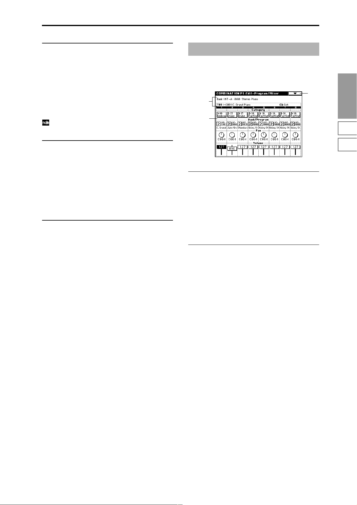
0–5b: Sampling Setup
Source BUS [L/R, Indiv.1/2]
Trigger [Sampling START SW, Note On]
Metronome Precount [Off, 4, 8, 3, 6]
Save to [RAM, DISK]
Mode (Sample Mode) [L-Mono, R-Mono, Stereo]
Sample Time [min sec]
Make settings for sampling in Combination mode. (☞Program P0: 0–3)
Sampling Setup settings apply to the entire Combination
mode; not to an individual combination.
Combination P1: Edit–Program/Mixer
1–1: Program/Mixer
For each timbre 1–8, set the bank, program, pan and volume.
0–1
1–1a
1–1b
Combination
P0
0–5c: Recording Level [dB]
ADC OVERLOAD !!
Recording Level [–inf, –72.0... 0.0...+18.0dB]
Adjusts the signal level at the final stage of sampling in
Combination mode. (☞Sampling P0: 0–1d)
This setting defaults to –12 dB when you turn on the power.
At a setting of –12 dB, CLIP will not appear even if you play
the Combinetion at its maximum level.
(☞Program P0: 0–3c “Recording Level”)
▼ 0–5: Page Menu Command
☞ 0–1A: Write Combination, 0–1B: Solo Selected Timbre,
Program P0: 0–3A: Metronome Setup,
Program P0: 0–3B: Optimize RAM,
Program P0: 0–3C: Select Bank & Smpl No.,
Program P0: 0–3D: Select Directory
P1 P2 P3 P4 P7 P8 P9
1–1a: Combination Name,
Selected Timbre Information
Combination Name
This shows the combination bank, number, and name
selected in Combination P0: Play.
Selected Timbre Information
Displays information about the selected timbre (1–8). (☞P0:
0–1b)
1–1b: Timbre Number, Category, Program Select,
Pan, Volume
Timbre Number (1...8)
Category [00...15]
Bank/Program (Program Select)
[INT-A...INT-F, G, g(1)...g(9), g(d), EXB-A...EXB-G]
Selects the program for each timbre.
These parameters can also be set from the P0: Play, Program
Select page. (☞P0: 0–1c)
Pan [RND, L001...C064...R127]
Volume [000...127]
Specifies the pan and volume of each timbre.
These parameters can also be set from the P0: Play, Mixer
page. (☞P0: 0–2a)
37
Page 49

Combination P2: Edit–Trk Param
2–1: MIDI Channel (MIDI Ch)
Here you can make MIDI settings for each timbre.
0–1
2–1a
2–1b
MSB
LSB
2–1a: Combination Name, Selected Timbre
Information, Timbre Number, Program
Category
Combination Name
Displays the bank, number, and name of the combination
selected in Combination P0: Play.
Selected Timbre Information
Displays information about the selected timbre (1–8). (☞P0:
0–1b)
Timbre Number (1...8)
Displays the timbre number. (☞P0: 0–1c)
Program Category
Displays the category of the program assigned to the timbre.
(☞P0: 0–2a)
2–1b: Status, MIDI Channel, Bank Select
Status [INT, Off, EXT, EX2]
“Status” can also be set from the P0: Play, Program Select
page. (☞P0: 0–1c)
MIDI Channel [01...16, Gch]
Sets the MIDI transmit/receive channel for each timbre 1–8.
Gch: The timbre will use the channel that has been selected
as the global MIDI channel “MIDI Channel” (Global P1: 1–
1a).
When “Status” is INT, MIDI messages will be received on
the channel you specify here. If this setting is the same as the
global MIDI channel, the internal tone generator will sound
according to the internal settings. If this is set to EXT or EX2,
playing the TRITON STUDIO will transmit MIDI messages
on the MIDI channel specified here. (Messages will also be
transmitted simultaneously on the global MIDI channel.)
Bank Select (When Status=EX2) [000:000...127:127]
Specifies the bank number that will be transmitted when
“Status” is set to EX2. The value at left is the MSB, and the
value at right is the LSB.
This setting has no effect if “Status” is other than EX2.
2–2: OSC
These settings specify how each timbre will be played.
0–1
2–1a
2–2a
2–2a: Force OSC Mode, OSC Select, Portamento
Force OSC Mode [PRG, Poly, MN, LGT]
Specifies the Voice Assign Mode (Program P1: 1–1b) of the
program selected for each timbre 1–8.
PRG: The settings of the program will be used.
Poly: The timbre will play polyphonically, regardless of the
settings of the program.
MN (Mono): The timbre will play monophonically, regardless of the settings of the program.
LGT (Legato): The timbre will play monophonically, with
single triggering (legato).
When using MN or LGT settings, the note priority will follow the “Priority” (Program P1: 1–1b) setting of the program.
OSC Select [BTH, OS1, OS2]
Specifies the “Oscillator Mode” of the program selected for
each timbre 1–8. If the “Oscillator Mode” (Program P1: 1–
1a) is Double, you can specify that either or both oscillators
sound.
BTH (Both): OSC1 and 2 will sound as specified by the set-
tings of the program.
OS1: Only OSC1 will sound.
OS2: Only OSC2 will sound. (If “Oscillator Mode” is Single
or Drums, there will be no sound.)
Portamento [PRG, Off, 001...127]
Make portamento settings for each timbre 1–8.
PRG: Portamento will be applied as specified by the pro-
gram settings.
Off: Portamento will be off, even if the original program settings specified for it to be on.
001...127: Portamento will be applied with the portamento
time you specify here, even if it is turned off by the program
settings.
If the “Status” (0–1c, 2–1b) is set to INT, CC#05 (portamento time) and CC#65 (portamento switch) messages
will be received and will control and change these settings. (If the setting is PRG, CC#05 portamento time
will not be received.) These messages will be received
on the MIDI channel specified for each timbre by “MIDI
Channel” (2–1b).
38
Page 50
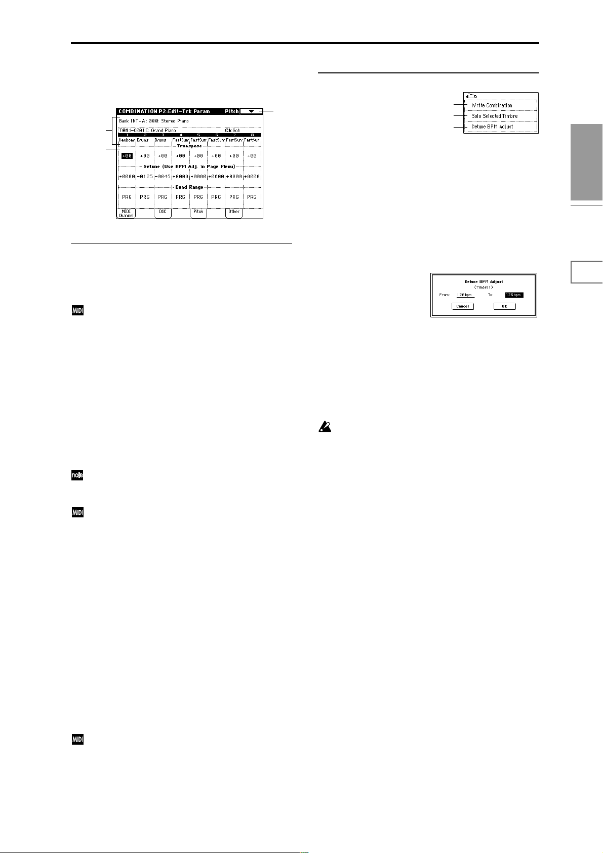
2–3: Pitch
Here you can make pitch-related settings for each timbre.
2–1a
2–3
▼ 2–3: Page Menu Command
0–1A
0–1B
2–3A
2–3a
2–3a: Transpose, Detune, Bend Range
Transpose [–24…+24]
Adjusts the pitch of each timbre in semitone steps.
12 units equal one octave.
When “Status” (0–1c, 2–1b) is INT, this parameter will
affect the pitches sounded by the TRITON STUDIO.
When “Status” is EXT, this parameter will affect the
note numbers of the MIDI note messages that are transmitted.
For example if you make settings of +04 and +07
respectively for two timbres that are set to EXT, playing
the C key will transmit a C note number on the global
MIDI channel, and at the same time will also transmit E
and G note numbers on the MIDI channels of those timbres.
Detune (Use BPM Adj. in Page Menu) [–1200...+1200]
Adjusts the pitch of each timbre in one-cent units.
0: Normal pitch.
You can also use the “Detune BPM Adjust” page menu
command to automatically make a detune setting from
a calculation in BPM units.
“Transpose” and “Detune” can be controlled via MIDI
RPN messages. Depending on the “Oscillator Mode”
(Program P1: 1–1a) settings of the programs used by
timbres 1–8, they can be controlled as follows.
When “Oscillator Mode” is Single or Double
MIDI RPN Coarse Tune can be received to control and
change the setting of “Transpose,” and RPN Fine Tune
can be received to control and change the setting of
“Detune.”
When “Oscillator Mode” is Drums
MIDI RPN Coarse Tune and Fine Tune can be received
to control and change the setting of “Detune.” The controllable range is ±1 octave for coarse tune and fine tune
together.
2–3A: Detune BPM Adjust
If the program of a timbre uses a phrase or rhythm loop
multisample (or sample that was created in the Sampling
mode) is matched to a specific BPM, you can use this Utility
to modify its BPM value. “Detune BPM Adjust” changes the
BPM of a phrase or rhythm by modifying its pitch.
This is valid only for a timbre when “Detune” is selected.
When this Utility is executed, the selected “Detune” value
will be set automatically. (☞Program P1: 1–2a, 1–2b, Global
P5: 5–1b, 5–1c)
1 Select “Detune BPM Adjust” to access the dialog box.
2 In “From” specify the original BPM value. In “To” spec-
ify the desired BPM value. The appropriate “Detune”
value will be calculated automatically from these two
values.
For example if you set “From” to 60 bpm and “To” to 120
bpm, the “Detune” parameter will be set to +1200 (one
octave up).
3 To execute the Detune BPM Adjust command, press the
OK button. To cancel, press the Cancel button.
The detune value that is calculated when you execute
this command will be added to “Detune” +0000. Y ou
must set the “From” BPM value when “Detune” is
+0000. For example if you execute “From” 60 bpm “To”
120 bpm, and then execute “From” 120 bpm “To” 60
bpm, will not return to the original result. (Rather, this
will set Detune= –1200, which is one octave down.)
Combination
P0
P1 P2 P3 P4 P7 P8 P9
Bend Range [PRG, –24...+24]
Specifies the amount of pitch change that will occur when
the pitch bender is operated, in semitone units.
PRG: The pitch range specified by the program will be used.
–24–+24: This setting will be used regardless of the setting in
the program.
The MIDI RPN Pitch Bend Change message can be
received to control this and change the setting. (However it will not be received if this parameter is set to
PRG.) This message is received on the MIDI channel for
each timbre set by “MIDI Channel” (2–1b).
39
Page 51
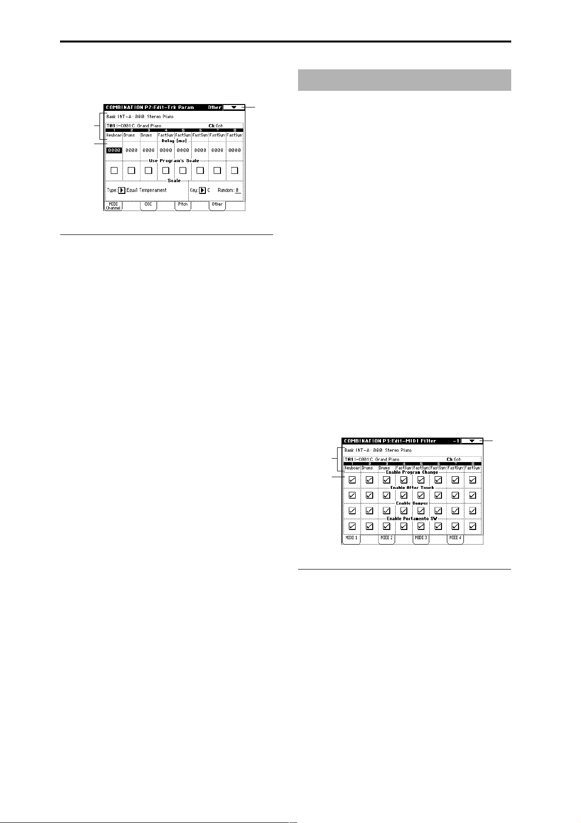
2–4: Other
Here you can make various other settings for each timbre.
0–1
2–1a
2–4a
2–4a: Delay, Use Program’s Scale, Scale
Delay [ms] (Delay Time) [0000…5000, KeyOff]
For each timbre, this specifies a delay time from note-on
until the sound begins.
KeyOff: The note will begin sounding at note-off. In this
case, the sound will not die away if the sustain level of the
program’s amp EG is other than 0. This setting is used when
creating harpsichord sounds.
Normally you will set this to 0.
Use Program’s Scale [Off, On]
Each timbre can use the scale that is specified by Scale (Program P1: 1–1c).
On (checked): The scale specified by the program will be
used.
Off (unchecked): The scale specified by Scale will be used.
Scale:
Specifies the scale that the combination will use.
Type (Combi's Scale)
[Equal Temperament...User Octave Scale15]
Select the type of scale (☞“Type” Program P1: 1–1c).
Combination P3: Edit–MIDI Filter
These settings allow you to apply filters to the MIDI data
that will be transmitted and received by each timbre 1–8. For
example even if two timbres are being played by the same
MIDI channel, you can make settings so that the damper
pedal will apply to one but not the other.
On (checked): Transmission and reception of MIDI data is
enabled. When “Status” (0–1c, 2–1b) is INT, operation of the
built-in controllers or incoming MIDI data will apply the
effect of the checked item to the program of the corresponding timbre. (The effect dynamic modulation function is not
affected by this setting.)
When “Status” is EXT or EX2, operation of the built-in controllers will transmit MIDI data on that timbre’s MIDI channel. MIDI transmission and reception settings for the entire
TRITON STUDIO are made in “MIDI Filter” (Global P1: 1–
1b).
The Edit–MIDI Filter-3 and -4 pages contain MIDI filters for
assignable controllers (whose function can be set by the
user), and if these are assigned to MIDI control changes, the
filter settings will affect those control changes.
In this case, if the assignable controllers have been set to
control changes that are also found in the Edit–MIDI Filter-1
or -2 pages, the settings in the MIDI 1 and MIDI 2 pages will
take priority. Also, if the same control change is assigned to
two or more controllers in the Edit–MIDI Filter-3 and -4
pages, checking any one of them will enable that control
change.
Off (unchecked): Transmission and reception of MIDI data
is disabled.
3–1: MIDI 1 (MIDI Filter –1)
0–1
2–1a
3–1a
Key [C…B]
Selects the tonic key of the selected scale (☞“Key” Program
P1: 1–1c).
Random [0…7]
As this value is increased, an increasingly random deviation will be added to the pitch at each note-on (☞“Random”
Program P1: 1–1c)
40
3–1a: Enable Program Change, Enable After T ouch,
Enable Damper, Enable Portamento SW
Enable Program Change [Off, On]
Specifies whether or not MIDI program change messages
will be transmitted and received.
Enable After Touch [Off, On]
Specifies whether or not MIDI after touch messages will be
transmitted and received.
Enable Damper [Off, On]
Specifies whether or not MIDI control change CC#64 hold
(damper pedal) messages will be transmitted and received.
Enable Portamento SW [Off, On]
Specifies whether or not MIDI control change CC#65 portamento on/off messages will be transmitted and received.
Page 52
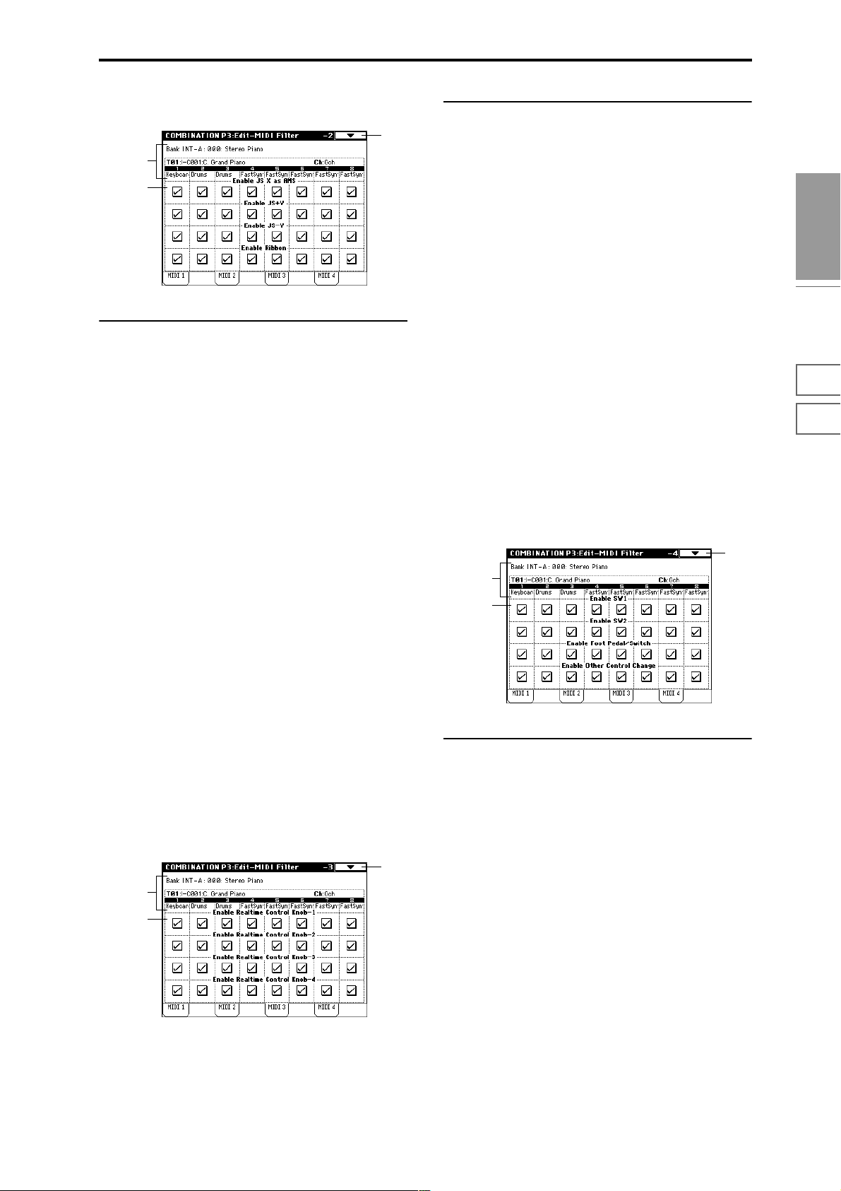
3–2: MIDI 2 (MIDI Filter –2)
0–1
2–1a
3–2a
3–2a: Enable JS X as AMS, Enable JS+Y,
Enable JS–Y, Enable Ribbon
Enable JS X as AMS [Off, On]
Specifies whether or not MIDI pitch bend messages (the X
axis of the TRITON STUDIO’s joystick) will be received to
control the AMS (“Alternate Modulation Source (AMS)”
☞p.241) effect assigned to JS X. (This is not a filter for MIDI
pitch bend message reception.)
Enable JS+Y [Off, On]
Specifies whether or not MIDI control change CC#1 (the +Y
axis of the TRITON STUDIO’s joystick, or specified as the
“B” assignment of a realtime control knob) will be transmitted or received.
Enable JS–Y [Off, On]
Specifies whether or not MIDI control change CC#2 (the –Y
axis of the TRITON STUDIO’s joystick, or specified as the
“B” assignment of a realtime control knob) will be transmitted or received.
3–3a: Enable Realtime Control Knob –1...4
Enable Realtime Control Knob –1 [Off, On]
Specifies whether or not the A-mode MIDI control message
CC#74 (the TRITON STUDIO’s low pass filter cutoff fre-
quency) and the B-mode MIDI control message assigned to
knob [1] will be transmitted and received.
Enable Realtime Control Knob –2 [Off, On]
Specifies whether or not the A-mode MIDI control message
CC#71 (the TRITON STUDIO’s low pass filter resonance or
high pass filter cutoff frequency) and the B-mode MIDI control message assigned to knob [2] will be transmitted and
received.
Enable Realtime Control Knob –3 [Off, On]
Specifies whether or not the A-mode MIDI control message
CC#79 (the TRITON STUDIO’s filter EG intensity) and the
B-mode MIDI control message assigned to knob [3] will be
transmitted and received.
Enable Realtime Control Knob –4 [Off, On]
Specifies whether or not the A-mode MIDI control message
CC#72 (the EG release time for the TRITON STUDIO’s filter
and amplifier) and the B-mode MIDI control message
assigned to knob [4] will be transmitted and received.
3–4: MIDI 4 (MIDI Filter –4)
0–1
2–1a
3–4a
Combination
P0
P1 P2 P3 P4 P7 P8 P9
Enable Ribbon [Off, On]
Specifies whether or not MIDI control change CC#16 (the
TRITON STUDIO’s ribbon controller, or specified as the “B”
assignment of a realtime control knob) will be transmitted or
received.
3–3: MIDI 3 (MIDI Filter –3)
Specifies whether or not the effects of A and B modes for the
REALTIME CONTROL knobs [1], [2], [3] and [4] will be
transmitted and received. In A-mode, the MIDI control message for each knob is fixed. In B-mode, the message for each
knob can be assigned in Controller page.
0–1
2–1a
3–3a
3–4a: Enable SW1, Enable SW2, Enable Other
Control Change
Enable SW1, Enable SW2 [Off, On]
Specifies whether or not the effect of the [SW1] and [SW2]
keys will be transmitted and received.
The function of these keys is specified in the P4: Edit-Zone/
Ctrl. Controller page.
This filter setting is valid for settings of SW1 Mod.: CC#80,
SW2 Mod.: CC#81, or Porta.SW: CC#65.
Enable Foot Pedal/Switch [Off, On]
Specifies whether or not the effect of the ASSIGNABLE
PEDAL/SWITCH will be transmitted and received. The
function is assigned in Global P2: Controller page.
This filter setting is valid when a MIDI control change is
assigned.
Enable Other Control Change [Off, On]
Specifies whether or not MIDI control messages not covered
in the preceding items MIDI Filter 1–4 will be transmitted
and received.
41
Page 53

Combination P4: Edit–Zone/Ctrl
4–1: Key Z (Key Zone)
These settings specify the keyboard range in which each
timbre will sound.
The top/bottom key parameters specify the range of notes
in which timbres 1–8 will sound, and the top/bottom slope
parameters specify the range over which the original volume will be reached.
By setting timbres of different sounds to ranges that do not
overlap, you can play different sounds in different ranges of
the keyboard (Key Split).
By setting the ranges to overlap, you can play two or more
sounds with a single note (Layer).
If you set the slopes (the grayed portion) to overlap, the
sounds will overlap, and the proportion of the overlap will
change according to the keyboard location (Positional
Cross-fade).
0–1
4–1a
Bottom Slope [00...72]
Specifies the range of keys (12 is one octave) over which the
volume will be reached starting from the bottom key.
0: The volume will be at the original level from the bottom
key.
12: The volume will increase gradually as you play upward,
and will reach the original volume one octave above the bottom key.
60: The volume will increase gradually as you play upward,
and will reach the original volume five octaves above the
bottom key.
Bottom Key [C–1...G9]
Specifies the bottom key (lower limit) of the notes that will
sound each timbre 1–8.
How volume will change according to keyboard location
Volume
Bottom Slope
Bottom Key
Top Slope
Top Key
Key
2–1a
4–1b
4–1a: Zone Map
This area indicates the note and velocity ranges in which
each timbre will sound.
The LCD screen will display a line to indicate the range of
notes and velocities that will sound, and will show the slope
portion in gray.
Bottom Slope
Bottom Key Top Key
Timbre 1
Key zone
display
Timbre 8
C-1 G9
Top Slope
Velocity zone
display
1 . . . 8
Timbre
Top Velocity
Top Slope
Bottom Slope
Bottom Velocity
4–1b: Top Key, Top Slope, Bottom Slope,
Bottom Key
Top Key [C–1...G9]
Specifies the top key (upper limit) of the notes that will
sound each timbre 1–8.
“T op Key” and “Bottom Key” settings can also be input
by holding down the [ENTER] key and playing a note
on the keyboard.
It is not possible to set the bottom key above the top key
of the same timbre. Nor is it possible for the top and
bottom slopes to overlap.
4–2: Vel Z (Vel Zone)
Sets the Top/Bottom Velocity parameters to specify the
range of velocities that will sound for each timbre 1–8, and
set the Top/Bottom Slope parameters to specify the range
over which the volume will change.
By setting two or more timbres to velocity zones that do not
overlap, you can use variations in playing dynamics to play
different sounds (Velocity Switch).
If you set two or more timbres to velocity zones that overlap,
the sounds will be heard together (Layer).
If the slope ranges (gray line) overlap, different sounds will
be sounded together, and your playing dynamics will determine the proportion of each sound (Velocity Cross-fade).
It is not possible to set the bottom velocity greater than
the top velocity for the same timbre. Nor can the top
slope and the bottom slope overlap.
0–1
4–1a
2–1a
Top Slope [00...72]
Specifies the range of keys (12 is one octave) over which the
volume will be reached starting from the top key.
0: The volume will be at the original level from the top key.
12: The volume will increase gradually as you play down-
ward, and will reach the original volume one octave below
the top key.
60: The volume will increase gradually as you play downward, and will reach the original volume five octaves below
the top key.
42
4–2a
Page 54

4–2a: Top Velocity, Top Slope, Bottom Slope,
Bottom Velocity
Top Velocity [1…127]
Specifies the maximum velocity value that will sound each
timbre 1–8.
Top Slope [0…120]
Specifies the number of velocity steps over which the original volume will be reached, starting from the Top Velocity.
0: The volume will be at the original value from the top
velocity.
120: The volume will decrease as the velocity approaches the
top velocity.
Bottom Slope [0…120]
Specifies the number of velocity steps over which the original volume will be reached, starting from the Bottom Velocity.
0: The volume will be at the original value from the bottom
velocity.
120: The volume will decrease as the velocity approaches the
bottom velocity.
Bottom Velocity [1…127]
Specifies the minimum velocity value that will sound each
timbre 1–8.
How volume will change according to keyboard location
Volume
4–4: Controller (Control)
Here you can set the Combination mode functions of the
[SW1] key, [SW2] key, and the B-mode functions of REALTIME CONTROL knobs [1]–[4].
0–1A
1–1a
4–4a
Combination
4–4b
P0
P1 P2 P3 P4 P7 P8 P9
4–4a: Panel Switch Assign
These settings assign the function of the [SW1] and [SW2]
keys (“SW1, SW2 Assign List” ☞p.249).
Since the function assignments of the [SW1] and [SW2] keys
made for the program assigned to each timbre are not valid
inside of a combination, they must be newly set using these
parameters.
SW1 (SW1 Assign) [Off, ..., After Touch Lock]
SW1 Mode [Toggle, Momentary]
SW2 (SW2 Assign) [Off, ..., After Touch Lock]
SW2 Mode [Toggle, Momentary]
☞ Program P1: 1–4a
Bottom Slope
Bottom Velocity Top Velocity
“Top Velocity” and “Bottom Velocity” settings can also
be input by holding down the [ENTER] key and playing a note on the keyboard.
Top Slope
Velocity
4–3: MOSS Setup (MOSS)
This page is displayed when the EXB-MOSS option has been
installed. For details refer to the owner’s manual included
with the EXB-MOSS.
4–4b: Realtime Control Knobs B-Assign
These settings assign functions (mainly various control
changes) to the B-mode of the REALTIME CONTROL knobs
[1]–[4] (“Realtime Control Knobs B–Assign List” ☞p.250).
The functions you specify here will be controlled when you
operate the REALTIME CONTROL knobs [1]–[4] in B-mode.
Since the REALTIME CONTROL knob [1]–[4] function
assignments made for the program assigned to each timbre
are not valid inside a combination, they must be newly set
using these parameters.
Knob 1-B [Off, ..., MIDI CC#95]
Knob 2-B [Off, ..., MIDI CC#95]
Knob 3-B [Off, ..., MIDI CC#95]
Knob 4-B [Off, ..., MIDI CC#95]
☞ Program P1: 1–4b
43
Page 55
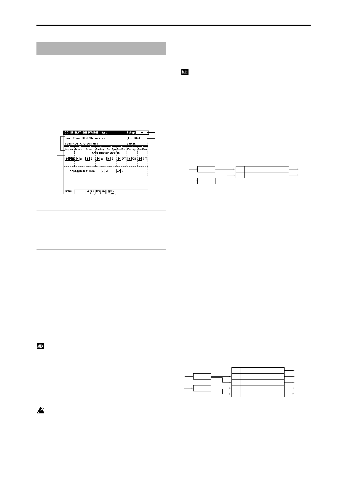
Combination P7: Edit–Arp.
These parameters specify how the arpeggiator will function
within the combination. Two arpeggiators can run simultaneously.
This offers a variety of possibilities, such as applying separate arpeggio patterns to two sounds that have been
assigned as a keyboard split, or using velocity to switch
between two arpeggio patterns.
7–1: Setup
7–1
2–1a
7–1b
7–1a: (Tempo) [040...240, EXT]
Specifies the tempo of the arpeggiator.
This can also be set by the [TEMPO] knob, or in the P0: Play
page. (☞0–1a)
7–1b: Arpeggiator Assign, Arpeggiator Run
Arpeggiator Assign [Off, A, B]
Assigns arpeggiator A or B to each timbre 1–8. When the
ARPEGGIATOR [ON/OFF] key is on, the arpeggiator specified for each timbre will operate according to “Arpeggiator
Run A, B” and these settings.
Off: The arpeggiator will not operate.
A: Arpeggiator A will operate. Use the settings in the Arpeg-
giator A page to select the arpeggio pattern and to set
parameters.
B: Arpeggiator B will operate. Use the settings in the Arpeggiator B page to select the arpeggio pattern and to set
parameters.
If the “Status” (0–1c, 2–1b) of the timbre is INT, each
timbre 1–8 will be sounded by the note data generated
by the assigned arpeggiator, regardless of the “MIDI
Channel” (2–1b) setting of the timbre. If a timbre is set
to EXT or EX2, MIDI note data will be transmitted on
the “MIDI Channel” of that timbre.
In this case, arpeggiator A (or B) will be triggered (operated) by all MIDI channels specified for the “MIDI
Channel” parameter of any timbre 1–8 assigned to
arpeggiator A or B.
If Local Control (“Local Control On,” Global P1: 1–1a) is
ON, the keyboard will not trigger the arpeggiator. The
arpeggiator will be triggered via MIDI IN. Turn Local
Control OFF if you have recorded only the trigger notes
on an external sequencer, and wish to playback the
external sequencer to trigger the TRITON STUDIO’s
arpeggiator.
7–1a
If you want the note data generated by the arpeggiator
to be recorded on the external sequencer, turn Local
Control ON, and turn off the echo back function on
your external sequencer.
You can control the arpeggiator from an external
sequencer, or use an external sequencer to r ecor d arpeggio note data. (☞p.266)
Example 1)
Set the “MIDI Channel” (2–1b) of timbres 1 and 2 to
Gch, and set “Status” (0–1c, 2–1b) to INT. Assign arpeg-
giator A to timbre 1 and arpeggiator B to timbre 2, and
check “Arpeggiator Run A, B” (0–3a, 7–1b).
• When the ARPEGGIATOR [ON/OFF] key is off, timbres
1 and 2 will sound simultaneously (layered) when you
play the keyboard.
• When the ARPEGGIATOR [ON/OFF] key is turned on,
timbre 1 will be played by arpeggiator A, and timbre 2
will be played by arpeggiator B.
Arpeggiator
Trigger
= Gch
Trigger
= Gch
Arpeggiator
A
Arpeggiator
B
Pattern - A
Pattern - B
Assign
A
Timbre 1 MIDI Ch=Gch Status=INT
B
Timbre 2 MIDI Ch=Gch Status=INT
Example 2)
The “MIDI Channel” (2–1b) of timbres 1, 2, 3, 4, and 5
are set respectively to Gch, Gch, 02, Gch, and 03. Their
“Status” (0–1c, 2–1b) is set respectively to INT, Off, INT,
Off, and INT. Assign arpeggiator A to timbres 2 and 3,
assign arpeggiator B to timbres 4 and 5, and check
“Arpeggiator Run A, B” (0–3a, 7–1b).
• When the ARPEGGIATOR [ON/OFF] key is off, playing
the keyboard will sound only timbre 1. (Timbres 2 and 4
are receiving the Gch, but they will not sound since their
“Status” is Off.)
• When you turn on the ARPEGGIATOR [ON/OFF] key,
arpeggiator A will operate for timbres 2 and 3, and
arpeggiator B will operate independently for timbres 4
and 5. (Arpeggiators A and B are triggered by receiving
note data on any MIDI channel of an assigned timbre,
but in this example they are being triggered from the
Gch.)
When you play the keyboard, arpeggiator A will operate
for timbres 2 and 3, but only timbre 3 whose “Status” is
INT will sound. Similarly, arpeggiator B will operate for
timbres 4 and 5, but only timbre 5 whose “Status” is INT
will sound.
In this way, you can make settings so that a timbre does
not sound when the arpeggiator is off, but sounds only
when the arpeggiator is on.
This type of setting is used in preloaded combinations
which sound the drums only when the arpeggiator is on.
Arpeggiator
Assign
Off
Trigger
= Gch, Ch2
Trigger
= Gch, Ch3
Arpeggiator
A
Arpeggiator
B
Pattern - A
Pattern - B
Timbre 1 MIDI Ch=Gch Status=INT
A
Timbre 2 MIDI Ch=Gch Status=Off
A
Timbre 3 MIDI Ch=2ch Status=INT
B
Timbre 4 MIDI Ch=Gch Status=Off
B
Timbre 5 MIDI Ch=3ch Status=INT
Sounded by normal
keyboard playing
Does not sound
Pattern - A
Does not sound
Pattern - B
Arpeggiator Run A, B
When the ARPEGGIATOR [ON/OFF] key is on, the arpeggiator(s) checked here will run if they are assigned to a timbre by “Arpeggiator Assign” (7–1b). (☞0–3a)
Pattern - A
Pattern - B
44
Page 56

▼ 7–1: Page Menu Command
0–1A
0–1B
7–1A
7–1A: Copy Arpeggiator
This command can copy arpeggiator settings from another
location to the current Combi.
1 Select “Copy Arpeggiator” to access the dialog box.
Key Sync.* [Off, On]
Keyboard* [Off, On]
These parameters are the arpeggiator settings for the combination. (☞“Program P7: Edit-Arpeggiator”)
* These parameters can also be set from “0–3(4): Arpegg.
A(B)”.
7–4: Scan Zone (Scan Zone A/B)
These settings specify the note and velocity ranges that will
operate arpeggiators A and B.
Combination
2 In “From” select the source (mode, bank, number) of the
arpeggiator you wish to copy.
If you are copying from Combination, Song, or Song Play
mode, select either A or B to if you wish to copy settings
from only one arpeggiator, or select A&B if you wish to
copy the settings of both arpeggiators.
3 If you are copying from a Program, or are copying either
A or B from Combination, Song, or Song Play mode,
select either A or B as the “To” copy destination.
4 To execute the Copy Arpeggiator command, press the
OK button. To cancel, press the Cancel button.
7–2: Arpegg. A (Arpeggiator A) 7–3: Arpegg. B (Arpeggiator B)
The Arpeggiator A pages allow you to adjust the settings for
arpeggiator A. The Arpeggiator B pages allow you to adjust
the settings for arpeggiator B.
You can also use the “Copy Arpeggiator” page menu
command to copy arpeggiator settings from Program
mode or another mode.
1–1a
7–1
7–1a
1–1a
7–4a
7–4b
7–1
7–1a
7–4a: Zone Map
This shows the Scan Zone for each arpeggiator, A and B.
Key zone of arpeggiator B
Key zone of arpeggiator A
C–1G9
Velocity zone of
arpeggiator A
Velocity zone of
arpeggiator B
7–4b: Scan Zone A/B
A:
Top Key [C–1...G9]
Bottom Key [C–1...G9]
Specifies the range of notes (keys) that will operate arpeggiator A. “Top Key” specifies the upper limit, and “Bottom
Key” specifies the lower limit.
P0
P1 P2 P3 P4 P7 P8 P9
7–2a
7–2(3)a: Arpeggiator-A(B) Setup
Pattern* [P00...P04, U000(I-A/B)...U506(User)]
Octave* [1, 2, 3, 4]
Resolution* [ , , , , , ]
Gate [000...100%, Step]
Velocity [001...127, Key, Step]
Swing [–100...+100%]
Sort* [Off, On]
Latch* [Off, On]
Top Velocity [001...127]
Bottom Velocity [001...127]
Specifies the range of velocities that will operate arpeggiator
A. “Top Velocity” specifies the upper limit, and “Bottom
Velocity” specifies the lower limit.
B:
Top Key [C–1...G9]
Bottom Key [C–1...G9]
Top Velocity [001...127]
Bottom Velocity [001...127]
Specifies the range of notes (keys) and velocities that will
operate arpeggiator B (☞A:).
The values of these parameters can also be entered by
holding down the [ENTER] key and playing a note on
the keyboard.
45
Page 57

Combination P8: Edit–Insert FX
0–1A
0–1B
8–1B
8–1C
8–1A
Y ou can also specify the bus routing for the pr ogram used by
each timbre 1–8.
☞ For details on insertion effects, refer to p.178 “8. Effect
Guide.”
8–1: Routing
Specifies the bus to which the program oscillator(s) used by
each timbre 1–8 will be sent. You can also set the send levels
to the master effects from this page.
8–1
8–1a
2–1a
8–1b
IFX2–IFX5) (8–2), and for the sound that has passed
through the IFX, set “BUS Select” (8–2) to either 1/2 or
3/4.
Send1 (MFX1) [000...127]
Send2 (MFX2) [000...127]
For each timbre 1–8, these parameters set the send level to
master effects 1 and 2. These settings are valid when “BUS
Select” is set to L/R or Off. When IFX 1, 2, 3, 4 or 5 are
selected, the send levels to master effects 1 and 2 are set by
the “Send 1” and “Send 2” parameters of the Insert FX page,
after the sound has passed through IFX1–5.
If “BUS Select” is set to 1, 2, 3, 4, 1/2, or 3/4, these settings are
ignored.
Control change CC#93 can be used to control the Send 1
level, and CC#91 to control the Send 2, and modify their
respective settings. These messages will be received on
the MIDI channel specified for each timbre in the P2:
MIDI channel page.
The actual send levels are determined by multiplying
this value with the send level “Send 1” and “Send 2”
(Program P8: 8–1d) for each oscillator of the program
selected for the timbre.
▼ 8–1: Page Menu Command
8–1a: Routing Map
This shows the status of the insert effects. For each insert
effect, this indicates the routing, the name of the selected
effect, the on/off status, and chain status.
The effect type, on/off status and chain status can be modified in the Insert FX page (8–2).
8–1b: BUS Select (IFX/Indiv.Out BUS Select),
Send1 (MFX1), Send2 (MFX2)
BUS Select (IFX/Indiv.Out BUS Select)
[DKit, L/R, IFX1...5, 1...4,1/2, 3/4, Off]
For each timbre 1–8, these parameters specify the bus to
which the program oscillator(s) will be sent. The current settings can also be viewed in the Routing Map.
DKit: This can be selected only if the program for which settings are being made is a drum program (“Oscillator Mode”
Drums). With a setting of DKit, the “BUS Select” (Global P5:
5–2b) setting made for each key of the drum kit will be used.
For example if the “BUS Select” settings of the drum kit
have assigned Snare sounds to IFX1 and Kick sounds to
IFX2, setting this parameter to DKit will send the Snare
sounds to IFX1 and Kick sounds to IFX2. If you wish to
modify these routings, use the page menu command “Drum
Kit IFX Patch” (8–1C).
If this is set to 1/2 or 3/4, the programs of timbres 1–8
will be sent in stereo from AUDIO OUTPUT (INDIVIDUAL) 1/2 or 3/4. If the pan of the program oscillator is
controlled by MIDI control change CC#10 (pan) or
AMS, the sound will be output with the pan setting that
is in effect at the moment of note-on. Unlike the case
when this parameter is set to L/R to output the sound
from (MAIN) L/MONO and R, the pan of a sounding
note will not change in realtime.
If you wish to move the pan of a sounding note in realtime and output it from AUDIO OUTPUT (INDIVIDUAL) 1/2 or 3/4, you must set “BUS Select” to IFX1
(or IFX2–IFX5), select 000: No Effect for “IFX1” (or
46
8–1A: Copy Insert Effect
☞ “Program P8: 8–1A: Copy Insert Effect.”
However, the MIDI control channel specified for “Ctrl Ch”
of the IFX1–5 pages will not be copied.
8–1B: Swap Insert Effect
☞ “Program P8: 8–1B: Swap Insert Effect.”
However, the MIDI control channel specified for “Ctrl Ch”
of the IFX1–5 pages will not be swapped.
8–1C: DrumKit IFX Patch
This command applies a patch to the “BUS Select” settings
of each key of the drum kit, allowing you to temporarily
change the connections to the insert effects. This command
is available only if a drum program has been selected for the
timbre and the “BUS Select” (8–1b) parameter is set to Dkit.
Furthermore, this command can be executed only if the
“BUS Select” (Global P5: 5–2b) for the individual keys of
that drum kit are set to IFX1–5.
1 Select “DKit IFX Patch” to access the dialog box.
2 In the Drum Kit “IFX” popup, select the insert effect to
which you want to patch.
3 To execute the Drum Kit Insert Effect Patch command,
press the OK button. To cancel, press the Cancel button.
To restore the condition of the drum kit, execute
IFX1→IFX1, IFX2→IFX2, IFX3→IFX3, IFX4→IFX4, and
IFX5→IFX5.
Page 58

8–2: Insert FX
Here you can select the type of each insert effect, turn it on/
off, and make chain settings etc.
8–1
8–2a
8–3: IFX 1 8–4: IFX 2 8–5: IFX 3 8–6: IFX 4 8–7: IFX 5
These are the parameters for IFX1, 2, 3, 4, and 5 that were
selected in the Insert FX page (☞p.187–).
8–1
8–3a
Combination
P0
8–2a: IFX1, 2, 3, 4, 5
IFX1, 5 [000...089]
IFX2, 3, 4 [000...102]
IFX1, 2, 3, 4, 5 On/Off [Off, ON]
Chain [Off, On]
Pan(CC#8) (Post IFX PanCC#8) [L000...C064...R127]
BUS Sel. (BUS Select) [L/R, 1, 2, 3, 4, 1/2, 3/4, Off]
Send1 [000...127]
Send2 [000...127]
These parameters are the same as in Program mode. (☞Program 8–2a)
However, unlike the case in Program mode, the “Ctrl Ch”
(8–3a – 7a) MIDI channel is used to control dynamic modulation (Dmod), “Pan (CC#8),” “Send1,” and “Send2” for the
insert effects. The control changes used are the same as in
Program mode.
P1 P2 P3 P4 P7 P8 P9
8–3(~7)a: Ctrl Ch
Ctrl Ch [Ch01...16, G ch, All Routed]
This parameter specifies the MIDI channel that will be
used to control effect dynamic modulation (Dmod), pan
following the insert effect (CC#8), Send 1, and Send 2.
The channel number of the timbre routed through this IFX
will be followed by a “*” displayed at the right of Ch01–16.
If two or timbres with different MIDI channel settings are
routed through the same IFX, this parameter specifies which
of these channels will be used to control the effect.
G ch: The global MIDI channel “MIDI Channel” (Global
mode P1: 1–1a) will be used to control the effect. Normally
you will set this to G ch.
All Routed: The channel of any timbre routed through this
effect can be used to control the effect. (Channels of each
routed timbre will be indicated by “*”.)
If the “BUS Select” (8–1b) of a timbre for which a drum
program is selected is set to DKit, the MIDI channel of
that timbre will be valid if any IFX1–5 is set to All
Routed, regardless of the “BUS Select” (Global P5: 5–
2b) settings or the settings of the “DrumKit IFX Patch”
page menu command.
47
Page 59

Combination P9: Edit–Master FX
☞ For details on master effects, refer to p.182 “8. Effect
Guide.”
9–1: Master FX
Here you can select the type of each master effect, turn it
on/off, and make chain and master EQ settings.
9–1a
9–2: MFX 1 9–3: MFX 2
Here you can set the parameters for the MFX 1 and 2 effects
that were selected in the Master FX page (☞p.187).
9–1
9–2a
9–1
9–1b
9–1c
9–1a: MFX1, 2
MFX1, 2 [000...089]
MFX1, 2 On/Off [Off, ON]
Chain [Off, On]
Chain Direction [MFX1→MFX2, MFX2→MFX1]
Chain Signal [LR Mix, L Only, R Only]
Chain Level [000...127]
9–1b: Return Level
Return 1, 2 [000...127]
9–1c: Master EQ Gain [dB]
Low [–18.0...+18.0]
Mid [–18.0...+18.0]
High [–18.0...+18.0]
These settings are the same as in Program mode (☞“Program 9–1: Master FX”).
9–2(3)a: Ctrl Ch
Ctrl Ch [Ch01...16, G ch]
This parameter specifies the MIDI channel that will
control dynamic modulation (Dmod) for the master
effect.
G ch: The global MIDI channel “MIDI Channel” (Global P1:
1–1a) will be used for control. Normally you will set this to
G ch.
9–4: Master EQ
The master EQ is a three-band stereo EQ. It is located immediately before the AUDIO OUTPUT (MAIN OUT) L/
MONO and R from the L/R bus, and adjusts the overall
tonal character of the sound (☞p.239).
0–1A
9–4a
▼ 9–1: Page Menu Command
0–1A
9–1A
9–1B
9–1A: Copy Master Effect
☞ “Program P9: 9–1A: Copy Master Effect.”
However, the MIDI contr ol channel that is specified by “Ctrl
Ch” of the MFX 1 and 2 pages will not be copied.
9–1B: Swap Master Effect
☞ “Program P9: 9–1B: Swap Master Effect.”
However, the MIDI contr ol channel that is specified by “Ctrl
Ch” of the MFX 1 and 2 pages will not be swapped.
48
9–4a: Ctrl Ch
Ctrl Ch [Ch01...16, G ch]
This parameter specifies the MIDI channel that will
control dynamic modulation (Dmod) for the master EQ.
G ch: The global MIDI channel “MIDI Channel” (Global P1:
1–1a) will be used for control. Normally you will set this to
G ch.
The MEQ High Gain and MEQ Low gain can be controlled
by assigning a modulation source to the “Low Gain ModSrc:” and the “High Gain Mod-Src:” functions on this page.
Page 60

3. Sequencer mode
In Sequencer mode you can use the built-in 16-track
sequencer to play, record, and edit songs. You can also
arrange multiple songs in the Cue List and play them back
in succession.
Here you can also record and edit patterns, copy a created
pattern or preset pattern into a song, or use patterns from
the RPPR (Realtime Pattern Play Recording) function.
Both songs and patterns can be recorded while using the
arpeggiator.
Executing the Sampling mode “Time Slice” command (Sampling P2: 2–1B) will divide the sample and will at the same
time create song performance data for these divided samples. You can then freely re-create the original rhythm loop
in various ways; for example you can change the song
tempo in Sequencer mode to play the rhythm loop at a different tempo without changing the pitch, or you can edit the
sequence data to change the note numbers or timing.
In addition, while the song plays back, you can play the keyboard or input an external audio source (e.g., vocal or guitar) from AUDIO INPUT etc. and sample it to automatically
capture audio data to go with your sequencer song. In other
words, you can create audio tracks while running the
sequencer, just as if you were using a recorder. (the In-Track
Sampling function)
You can also sample performances produced by playing
songs, patterns, cue lists, the arpeggiator, or RPPR.
Furthermore, a song you create can be resampled to the
internal hard disk, and then, using the included CDRW-1
option etc., written to a CD in Disk mode to produce an
audio CD. (☞BG p.118)
These settings and any song data that you have
recorded will not be backed up when the power is
turned off. Before turning off the power, be sure to save
important data on a floppy disk, hard disk, CD-R/RW,
external SCSI device, or a data filer. Immediately after
the power is turned on, memory will not contain any
song data, so in order to playback the sequencer, you
will need to load data from the floppy disk etc., or
receive a MIDI bulk data dump from an external MIDI
sequencer (☞p.144).
Sequencer P0: Play/Rec
0–1: Prog. 1–8 (Program T01–08) 0–2: Prog. 9–16 (Program T09–16)
Here you can make basic settings for recording and playing
back songs, and can select the program that will be used by
each track.
0–1
0–1a
0–1b
0–1c
0–1a: Location, Meter, Tempo, Tempo Mode, Song
Select, Track Select, Reso, RPPR On/Off
Location [001:01.000…999:16.191]
This display shows the current position in the song.
From the left, the numbers are the measure, beat, and clock.
When you modify these values, the current location will
change.
When “MIDI Clock” (Global P1:1–1a) is set to Internal,
changing the location will cause Song Position Pointer
messages to be transmitted. Also if the “MIDI Clock”
parameter is set to External MIDI or External mLAN,
and “Receive Ext. Realtime Command” (Global P1: 1–
1a) is on, the location will change if a Song Position
Pointer message is received from the specified source.
The range in which the beat and clock can be modified
will depend on the currently specified time signature.
Sequencer
P0
P1 P2 P3 P4 P5 P6 P7 P8 P9
Meter [**/**, 1/4…16/16]
This is the time signature at the current location of the song.
The time signature can be changed at each measure.
**/**: This will be displayed when you press the
SEQUENCER [REC/WRITE] key. Specify this when you
wish to use the time signature that is already recorded for
that measure, and wish to record without changing the time
signature.
1/4–16/4, 1/8–16/8, 1/16–16/16: This is the time signature at
the current location of the song.
After pressing the SEQUENCER [REC/WRITE] key, specify
the time signature here. Then press the SEQUENCER
[START/STOP] key to begin recording, and the specified
time signature will be recorded on the Master Track and on
previously-recorded tracks. Be aware that if you press the
SEQUENCER [START/STOP] key during the pre-count to
stop recording, the time signature will not be recorded.
Normally, you will specify the time signature when you
record the first track, and select **/** when recording subsequent tracks.
49
Page 61

Recording from measure 2 of track 2
Track 1
Track 2
Track 1
Track 2
when Meter = **/**
1 (4/4) 2 (3/4)
1 (4/4)
1 (4/4) 2 (3/4)
1 (4/4) 2 (3/4)
3 (4/4)
Recording
3 (4/4)
3 (4/4)
Track 1
Track 2
Track 1
Track 2
when Meter =7/8
1 (4/4) 2 (3/4)
1 (4/4)
1 (4/4) 2 (7/8)
1 (4/4) 2 (7/8)
3 (4/4)
Recording
3 (7/8)
3 (7/8)
3 (4/4)
4 (7/8)
4 (7/8)
Changing the time signature in the middle of a song
If you know beforehand the location at which you wish to
change time signatures in the middle of a song, use “Insert
Measure” (5–1H) to specify and insert the time signature for
each measure of the same time signature, and then record
your musical data. Alternatively, if you wish to change the
time signature in the middle of a song which already contains musical data, use “Track Select” to specify the Master
Track (or any Track01–16 which contains data), and use
“Event Edit” (5–1B) to modify the time signature of the Bar
event.
If the number of beats in a measure increases when you
modify the time signature, rests will be inserted in the portion that was added. Conversely if the number of beats
decreases, that portion will not be played. However if you
return to the original time signature, the data that had been
hidden will once again be played. (The data itself will not be
erased.)
Rest is inserted
Not played
(Tempo) [040…240, EXT]
This sets the playback tempo of the song and the tempo of
the arpeggiator.
040...240: When the “Tempo Mode” is Manu, this tempo
will be used for recording and playback. When “Tempo
Mode” is REC, this tempo will be recorded on the master
track.
EXT: This will appear when “MIDI Clock” (Global P1: 1–1a)
is either External MIDI or External mLAN. The tempo of
the internal sequencer will synchronize with the MIDI Clock
messages received from an external sequencer etc. When
“MIDI Clock” is Internal, the above tempo setting
(040...240) will be used.
If Tempo is selected as an alternate modulation source,
= 120 will be the base value.
Tempo Mode [Auto, Manu, REC]
Auto: The tempo will follow the tempo of the Master Track.
The tempo of the master track can be specified by using
“Event Edit” (5–1B) with Master Track chosen in “Track
Select,” or by the REC operation described below. When
Auto is selected, it will not be possible to modify the “
(Tempo)” setting while a song is playing or recording (or
during standby).
Manu (Manual): The “ (Tempo)” setting will be used.
REC: Tempo changes will be recorded on the Master Track.
Select this after pressing the SEQUENCER [REC/WRITE]
key. When REC is selected and you are recording in realtime, modify the “Tempo” value to change the tempo. This
cannot be selected when the Preferences page item “Record-
ing Setup” is set to Loop All Tracks. Tempo changes can
also be created using “Event Edit” (5–1B) or “Create Control
Data” (5–1L).
If you wish to record only the tempo changes, set
“Recording Setup” (0–8a) to OverDub, and the tempo
will be recorded on the master track without being
affected by the musical data of “Track Select.”
Song Select [000…199]
Select the song that you want to record or play back.
Either select the song name from the popup menu, or use
numeric keys [0]–[9] to specify the song number and then
press the [ENTER] key.
If you want to create a new song, choose a number from the
popup menu whose song name is blank, or use the numeric
keys [0]–[9] to specify the song number and press the
[ENTER] key to access the dialog box. Then specify “Set
Length” to specify the number of measures in the song, and
press the OK button.
If you want to change the length of a song after creating
it, execute the page menu command “Set Song Length”
(5–1Q). When creating a new song, you can specify the
length to be somewhat longer than necessary, and after
you have finished recording and editing, use “Set Song
Length” to specify the correct length.
If “MIDI Clock” (Global P1: 1–1a) is Internal, changing
the song will cause Song Select and Song Position
Pointer messages to be transmitted. If “MIDI Clock” is
External MIDI or External mLAN, Song Select messages can be received from the specified source to
change songs.
When the song changes, tracks whose track status
(“Status” (2–1a)) is EXT, EX2 or BTH will transmit Bank
Select, Program Change, Volume, Panpot, Poramento,
Send1, 2, Post IFX Pan, and Post IFX send 1, 2 messages
on the MIDI channel of the respective track.
Track Select [Track01…Track16, Master Track]
Track01–Track16: Select the track(s) that will record or play
song data.
The track names specified in “Track Name” (5–2).
When you perform realtime recording on a single track, the
musical data will be recorded on the track you select here.
When you perform realtime recording on two or more tracks
simultaneously (☞“Multi REC” 0–8a), the “PLAY/MUTE/
REC” (0–1c) will select the recording track, regardless of the
setting you make here.
Master T rack: Selects the master track when you wish to use
the P5: Track Edit page menu commands to edit the tempo
track. When using realtime recording or step recording, it is
not possible to record the master track alone.
When you play the keyboard of the TRITON STUDIO
and operate its controllers, the internal tone generator
will sound according to the settings (program, level
etc.) of the tracks that are selected here (if “Status” 2–
1a/2a is INT or BOTH), and other tracks whose MIDI
channels match will also sound at the same time (if
“Status” is INT or BOTH). Messages will also be transmitted on the MIDI channels of these tracks (whose
“Status” is EXT, EX2 or BOTH).
50
Page 62

Reso (Realtime Quantize Resolution) [Hi, 3 … ]
This corrects the timing of data as it is recorded in realtime.
(It does not affect previously-recorded data.)
Hi (High Resolution): Timing will not be corrected. Data
will be recorded at the maximum resolution (/192).
3 – : Data will be corrected to the nearest interval of the
specified timing as it is recorded. For example if you select
3 , data will be corrected to the nearest 32nd note triplet
interval. If you select , data will be corrected to the nearest
quarter note interval.
With a setting of
Since all that musical data that is recorded will be corrected
to the specified timing resolution, coarse settings of this
parameter will cause continuous controllers such as pitch
bend to be recorded in “stairstep” fashion.
In such cases, use a setting of Hi to record, and then use
“Quantize” (5–1N) to correct only the desired type of data
(notes etc.). It is best to avoid recording at a stiff resolution
to begin with.
RPPR On/Off [Off, On]
This turns the RPPR (Realtime Pattern Play/Recording)
function on/off. RPPR lets you assign a pattern to each note
of the keyboard, so that the pattern will playback (or be
recorded) when you press the appropriate key.
On (checked): The RPPR function will be on. If a pattern
has been assigned to each key in the P6: Pattern/RPPR,
RPPR Setup page, pressing that key will perform the
assigned pattern (☞P6–3: RPPR Setup).
0–1(2)b: Selected Track Information
Displays information for the track (1–16) that is currently
being edited or selected by “Track Select.”
T (Track) (01...08 (09...16))
Indicates the track number and the program bank/number/
name specified for that track.
Ch (01...16)
Indicates the MIDI channel number specified for the track.
RPPR (NoAssign, C#2...C8)
This shows the key number(s) that will start the RPPR pattern assigned to the track. (If there are numerous keys, not
all will be shown. T o view all of the assignments, use the P6:
Pattern/RPPR, Pattern Edit page.)
When you press the popup button, the Category/Track Program Select menu will appear.(“Category/Program Select
menu” ☞Program P0: 0–1a)
Program Select (Bank/Program)
[INT-A...INT-F, G, g(1)...g(9), g(d), EXB-A...EXB-G]
Selects the program that will be used by the track.
The lower line displays part of the program name.
If “Program Select” is selected, you can use the BANK [INTA]–[EXB-G] keys and VALUE controller to make the setting.
If you press the popup button, the Bank/Track Program
Select menu will appear, allowing you to select a program.
(“Bank/Program Select menu” ☞Program P0: 0–1a)
If you select “Program Select,” the BANK key LED will
light to indicate the bank of the program selected for
the track.
Bank INT-F can be selected if the EXB-MOSS option is
installed. If this is installed, 128 special EXB-MOSS programs can be used.
The program you select here will be used when the song is
played or recorded from the beginning. If the program is
changed while recording, the program change will be
recorded as musical data, and the program will change during playback. You can also change the program manually
during playback. However if musical data (program change
data) is already recorded, the program will change at that
point.
If the “Status” (2–1a/2a) is either INT or BTH, programs can be selected by receiving MIDI program
change messages. Also, when the song is changed or
when the song returns to the beginning, tracks whose
“Status” is EXT, EX2 or BTH will transmit the bank and
program numbers via MIDI. Tracks whose “Status” is
EX2 will show Bank as “–” and will transmit the bank
number that was selected in the “Bank Select” (2–1a/
2a) setting.
PLAY/MUTE/REC [PLAY, MUTE, REC]
Here you can mute each track, and select the recording
track(s) when performing multi-track recording. During
playback, or for single-track recording (normal recording), it
is possible only to select PLAY or MUTE for tracks (play-
back tracks) other than the recording track. For multi-track
recording, tracks can be set to PLAY, MUTE, or REC. The
setting will alternate each time you press the PLAY/MUTE/
REC button.
PLAY: The track will play.
MUTE: The track will be muted (silent).
REC: This will be displayed during single-track recording
(normal recording). It cannot be selected.
When you use multi-track recording (the Preferences page
“Multi REC” is on), select REC for the tracks that you wish
to record.
Sequencer
P0
P1 P2 P3 P4 P5 P6 P7 P8 P9
0–1(2)c: Track Number, Category, Bank/Program,
PLAY/MUTE/REC, SOLO ON/OFF
Track Number (1...8 (9...16))
Indicates the track number.
Use the parameters located below “Track Number” to make
settings for that track number.
Category [00...15]
The program to be used by the track can be selected by category. All programs are classified into one of sixteen categories. You can select the desired category, and then choose
programs from that category.
SOLO ON/OFF [SOLO ON, SOLO OFF]
This turns the Solo function on/off.
Only the track that is set to SOLO ON will sound. Other
tracks will be muted.
The setting will alternate on/off each time you press the
SOLO ON/OFF button.
If tracks whose “Status” (2–1a/2a) is BTH, EXT, or EX2
are muted by Mute or by the Solo function, note on/off
messages will not be transmitted on the MIDI channel
selected for those tracks.
51
Page 63

When the page menu command “Solo Selected Track”
(0–1B) is on, its Solo status will be given priority (if
ON). When you press “SOLO ON/OFF” or the parameter of another track, only that track will be soloed, and
will sound.
▼ 0–1: Page Menu Command
0–1E: Copy From Song
This command copies all of the setting data and musical
data from the specified song to the currently selected song.
1 Select “Copy From Song” to access the dialog box.
0–1A
0–1B
0–1C
0–1D
0–1E
0–1F
0–1G
0–1H
0–1I
0–1J
0–1K
0–1A: Memory Status
This displays the remaining amount of sequencer memory.
0–1B: Solo Selected Track
The Solo function will alternate on/off each time you select
this command.
1 Select the page menu command “Solo Selected Track.”
When you select this command, a check mark will be
added at the left of the “Solo Selected T rack” in the menu,
and the Solo function will be turned on.
2 In a page that displays parameters for each track, select
the track that you want to solo (e.g., by using “Program
Select” in the P0: Play, Program Select page), and only
that track will sound, while the other tracks will be
muted. The “Selected Track Information” (0–1b/2b) in
each page will indicate [Solo]. This function cannot be
selected in pages that do not contain parameters for individual tracks.
If you want to solo another track, select a parameter of
that track.
3 To cancel the Solo function, once again choose “Solo
Selected Track.”
When this Solo function is on, only the selected track
will be soloed and will sound when you press “SOLO
ON/OFF” (0–1c/2c) or a parameter of another track –
even if two or more “SOLO ON/OFF” buttons are
turned on.
If the tracks that have been muted by the Solo function
have a “Status” (2–1a) setting of EXT, EX2, or BTH, the
MIDI note-on/off messages of that track will not be
transmitted.
0–1C: Rename Song
Here you can rename the selected song. A name of up to sixteen characters can be input. (☞BG p.53, 57)
0–1D: Delete Song
This command deletes the currently selected song.
1 Select “Delete Song” to access the dialog box.
2 If you wish to execute the Delete Song command, press
the OK button. To cancel, press the Cancel button.
When you execute this command, the musical data, setting data, and patterns etc. of the currently selected song
will be erased, and the memory area allocated to that
song will be freed.
2 In “From,” specify the copy source song number.
3 Select the data that you wish to copy.
All: will copy all setting data and musical data (track
events and patterns, etc.).
Without Track/Pattern Events: will copy only the setting
data of songs, except for Play Loop and RPPR data.
4 To execute the Copy Song operation, press the OK but-
ton. To cancel, press the Cancel button.
Be aware that if you execute “All,” all setting data and
musical data of the currently selected song will be erased
and rewritten by the data from the copy source song. If
you execute “Without Track/Pattern Events,” song set-
ting data other than Play Loop and RPPR will be rewritten.
0–1F: Copy From Combi (Copy from Combination)
This command copies the parameters of the specified combination to the setting data of the currently selected song.
1 Select “Copy From Combi” to access the dialog box.
2 In “Combination,” select the copy source destination.
3 Use “with Effects” to specify whether effect and EQ set-
tings will also be copied.
If this is checked, insert effects, master effects, and master EQ settings will also be copied.
4 Use “To” to select the copy-destination tracks (1–8 or 9–
16).
5 If you selected Track 1 to 8 as the “To” setting, you have
the option of checking “Auto adjust Arp setting for
Multi REC.” As necessary, this function will adjust the
MIDI channel etc. of any tracks that need to be changed,
and/or add new tracks, in order to ensure that when you
perform multi-recording with the arpeggiator on, the
same sound will be reproduced during recording as during playback.
This function makes adjustments depending on the
ARPEGGIATOR [ON/OFF] state of the combination.
When you copy a combination that was written with
the arpeggiator turned off, it is assumed that you will
leave the arpeggiator off in the song as well. If you
want to use the arpeggiator in the song, you should
write the combination with the arpeggiator turned on,
and then copy it to the song.
If this is checked, the MIDI channels etc. of the tracks
will be corrected. “Multi REC” (0–8a) and “PLAY/
MUTE/REC” (0–1c/2c) will also be set automatically. In
addition, “Recording Setup” Over Write (0–8a) will be
selected. (Note that the automatically-set “Multi REC”
and “PLAY/MUTE/REC” will be reset when you reselect the song.)
52
Page 64
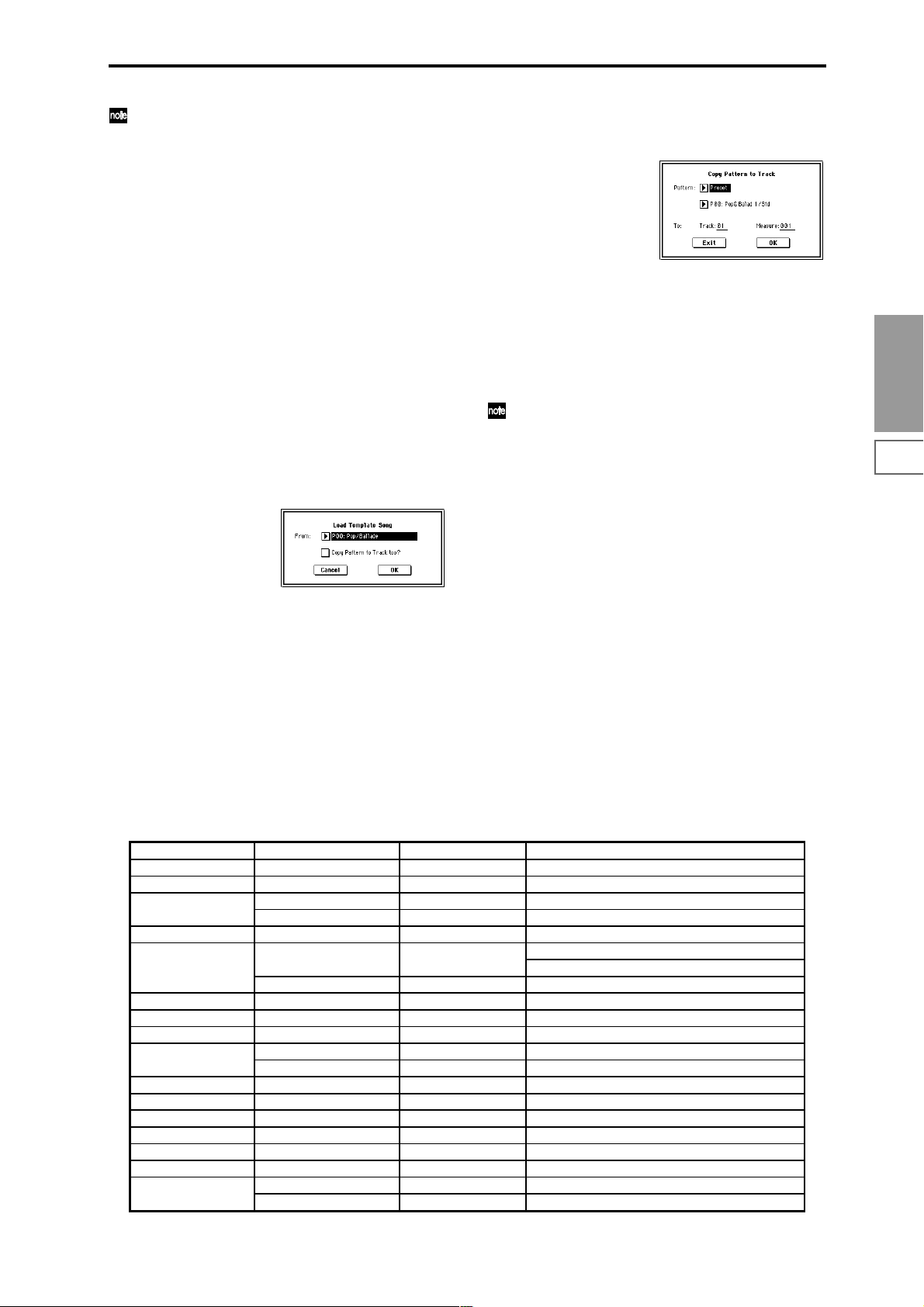
For details on the content that will be corrected, refer to
“If the recorded performance is not reproduced correctly during playback” (☞BG p.96). The content
described here will be corrected automatically. Depending on the settings of the combination, it may be necessary to make additional changes to the track settings in
addition to the settings here.
6 Press the OK button to execute the Copy From Combination
command, or press the Cancel button to cancel without
executing.
When you execute the command, the song setting data of
the currently selected song will be erased, and overwritten by the settings of the combination.
0–1G: Load Template Song
This command loads a template song as a song.
The built-in sequencer contains sixteen different preset tem-
plate songs (P00–15) that contain preset settings for pro-
grams and effects appropriate for various musical styles.
Y ou ar e also free to create your own favorite settings for programs, track parameters, and effects, and save them as one
of sixteen user template songs (U00–15) (☞“Save as User
Template Song” 0–1H).
1 Select “Load Template Song” to access the dialog box.
2 In “From,” specify the template song that you wish to
load.
3 If you check “Copy Pattern to Track too?,” the “Copy
Pattern To Track” dialog box will appear automatically
after “Load Template Song” has been executed.
If you execute without checking this, only the template
song you specified in step
4 To load the template song, press the OK button. To can-
cel without loading, press the Cancel button.
When you execute, song settings other than Play Loop
and RPPR will be copied.
2 will be loaded.
If in step
3 you checked “Copy Pattern to Track too?”
and pressed the OK button, the “Copy Pattern To T rack”
dialog box will appear.
This dialog box is the same as in the page menu command “Copy To Track” (6–1I) (☞p.78).
5 In “Pattern,” select the pattern that you wish to copy. If
you press the SEQUENCER [START/STOP] key, the
selected pattern will play.
In To “Track,” select the copy destination track.
In “Measure,” specify the beginning measure of the copy
destination.
Track 1 of all sixteen preset template songs contains a
drum category program. (In preset template songs P02,
P04, P08, and P15 drum category programs are specified for multiple tracks.)
The pattern names of the 150 preset patterns indicate
the musical genre and part of the optimal drum category program. (☞table below)
For example in P00: Pop&Balad 1/Std, the musical
genre is “Pop&Balad 1,” and “Std” is part of the name
of the drum category program that is most suitable.
By loading the drum track for these preset template
songs and the corresponding preset patterns, you can
efficiently set up a drum track that is suited to each preset template song.
6 To execute, press the OK button. When you execute,
“Measure” will count up automatically. You may then
copy patterns as well. To exit the command, press the
Exit button.
☞ For details on how to copy preset patterns to a song along
with the preset template song, refer to BG p.49.
Sequencer
P0
P1 P2 P3 P4 P5 P6 P7 P8 P9
Preset Template Song Track No.: Name Program Corresponding Preset Pattern No.:Name
P00: Pop/Ballade Track01: Drums A036:Standard Kit P00: Pop&Balad 1/Std ... P10: Pop(6/8) 3/Std
P01: Rock/Metal Rock Track01: Drums B020:Processed Kit P11: Rock 1/Process ... P21: Rock11/Process
P02: R & B Track01: Drums 1(Std 2) B036:Standard Kit 2 P22: R&B 1/Std2 ... P27: R&B 6/Std2
Track09: Drums 2(Std) A036:Standard Kit P28: R&B 7/Std ... P32: R&B11/Std
P03: Jazz Track01: Drums B004:Jazz/Brush Kits P33: Jazz 1/Jazz ... P39: Jazz 7/Jazz
P04: Latin Track01: Drums B004:Jazz/Brush Kits P40: Latin 1/Jazz ... P42: Latin 3/Jazz
P46: Latin 7/Jazz ... P47: Latin 8/Jazz
Track08: Percussion B116:Percussion Kit P43: Latin 4/Perc ... P45: Latin 6/Perc
P05: Reggae Track01: Drums B068:Drum'nBass Kit P48: Reggae 1/D'n'B ... P53: Reggae 6/D'n'B
P06: Country Track01: Drums A036:Standard Kit P54: Country 1/Std ... P57: Country 4/Std
P07: Folk Track01: Drums A036:Standard Kit P58: Folk 1/Std ... P61: Folk 4/Std
P08: European Trad. Track01: Drums A036:Standard Kit P62: E.Trad 1/Std ... P67: E.Trad(3/4)2/Std
Track08: Percussion B116:Percussion Kit —
P09: Orchestral Track01: Percussion A116:Orchestra&Ethnic —
P10: Techno/Euro Beat Track01: Drums A020:House Kit P68: Techno 1/House ... P78: Techno11/House
P11: House Track01: Drums A020:House Kit P79: House 1/House ... P92: House14/House
P12: Drum'n'Bass Track01: Drums B068:Drum'n'Bass Kit P93: Drum'nBs 1/D'n'B ... P108: Drum'nBs16/D'n'B
P13: Acid Jazz Track01: Drums B036:Standard Kit 2 P109: AcidJazz 1/Std2 ... P120: AcidJazz12/Std2
P14: Hip Hop/Rap Track01: Drums A068:HipHop Kit P121: HipHop 1/HipHop ... P135: HipHop15/HipHop
P15: Big Beats Track01: Drums 1(Hip/Hop) A068:HipHop Kit P136: Bigbeat 1/HipHop ... P143: Bigbeat 8/HipHop
Track09: Drums 2(Tricky) A004:! {Tricky} Kit! P144: Bigbeat 9/Tricky ... P149: Bigbeat14/Tricky
53
Page 65

0–1H: Save Template Song
(Save as User Template Song)
This command saves the program selections, track parameters, and effect settings etc. of the current song as a user template song U00–15. The settings you save here can also be
loaded in Song Play mode.
1 Select “Save Template Song” to access the dialog box.
2 In “To,” specify the user template song (U00–15) in
which the data will be saved.
3 To save the template song, press the OK button. To can-
cel, press the Cancel button.
Be aware that when you execute this command, all setting data of the save destination User T emplate Song will
be erased and rewritten with the current settings.
0–1I: FF/REW Speed
This allows you to set the speed at which fast-forward or
rewind will occur when you press the [FF] key or [REW]
key.
1 Select “FF/REW Speed” to access the dialog box.
3 If “Ignore Tempo” is checked, the playback tempo and
note length will be ignored, and fast-forward and rewind
will be performed as fast as possible. The speed of fastforward and rewind will differ between sections where
the playback data is dense and sections where it is sparse.
If this item is unchecked, fast-forward and rewind will
be performed at the speed you specify for “Speed.”
4 To execute the settings, press the OK button. To cancel,
press the Cancel button.
0–1J: Set Location (Set Location for Locate Key)
When you press the [LOCATE] key, you will move to the
location specified here.
1 Select “Set Location” to access the dialog box.
2 In “Location,” specify the location to which you will
move when you press the [LOCATE] key. If you specify
001:01:000, you will move to the beginning of the song
when you press the [LOCATE] key.
3 To execute the settings, press the OK button. To cancel,
press the Cancel button.
When this dialog box is not open, you can hold down
the [ENTER] key and press the [LOCA TE] key to set the
current location as the “Set Location” value.
0–1K: GM Initialize
2 In “Speed,” specify the speed (relative to the playback
tempo) at which fast-forward and rewind will occur.
This setting is relative to the playback tempo.
With a setting of 2, this will occur at double the playback
tempo; with a setting of 3, triple the tempo; and with a
setting of 4, quadruple the tempo. However in sections
where the playback data is dense, the fast-forward or
rewind speed may slow down.
This command transmits a GM System On message to the
Sequencer mode, resetting all tracks to the GM settings
(☞table below).
GM Initialize Parameter
Parameter Track1–9, 11–16 Track10
P0 Bank/Program (Program Select) G001:Acoustic Piano g(d)001:STANDARD Kit
Pan C064 C064
Volume 100 100
P1 Status – – The setting remains unchanged
Use Program’s Scale – – The setting remains unchanged
P7 Arpeggiator Assign – – The setting remains unchanged
Other Arpeggiator parameters – – The setting remains unchanged
P8 IFX/Indiv.Out BUS Select L/R DKit
Send1(MFX1) 0 0
Send2(MFX2) 40 40
IFX1–5 – – The setting remains unchanged
Pan(CC#8) – – The setting remains unchanged
BUS Select – – The setting remains unchanged
Send1 – – The setting remains unchanged
Send2 – – The setting remains unchanged
Other Insert Effect parameters – – The setting remains unchanged
P9 MFX1 – – 016: Stereo Chorus
MFX2 – – 053: Reverb SmoothHall
Return1 – – 127
Return2 – – 050
Other Master Effect and Master EQ parameters – – Default settings
54
Page 66
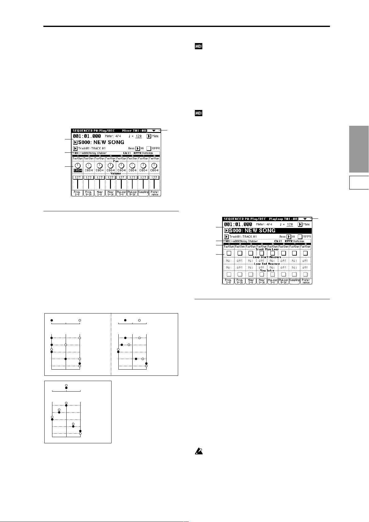
0–3: Mixer 1–8 (Mixer T01–08) 0–4: Mixer 9–16 (Mixer T09–16)
Here you can set the pan and volume of each track.
The pan and volume that you specify here will be used
when you playback or record from the beginning of the
song. If you change the settings during recording, the
changes will be recorded as musical data, and pan and volume will change during playback. You can also change the
settings during playback. However when the song reaches a
location where pan or volume data was recorded, the settings will change accordingly.
0–1
0–1a
0–1b
0–3a
0–3(4)a: Track Number, Program Category, Pan,
Volume
Track Number (1...8 (9...16))
Indicates the track number. (☞0–1c/2c)
Program Category
Partially displays the name of the category used by the
track.
If “Status” (2–1a/2a) is INT or BTH, CC#10 Panpot can
be received to control the panning. When receiving
CC#10, a value of 0 or 1 is far left, 64 is center, and 127 is
far right. When you change the song or return to the
beginning of the song, tracks whose “Status” is EXT,
EX2 or BTH will transmit the pan you specify here as a
MIDI message (except for RND).
Volume [000...127]
Sets the volume of tracks 1–16.
When “Status” (2–1a/2a) is INT or BTH, CC#7 Volume
can be received to control the volume. The volume of a
track is determined by multiplying the MIDI Volume
(CC#7) and Expression (CC#11) values. When you
change the song or return to the beginning of the song,
tracks whose “Status” is EXT, EX2 or BTH will transmit
the volume you specify here as a MIDI Volume message.
0–5: PlyLoop 1–8 (PlayLoop T01–08) 0–6: PlyLoop 9–16 (PlayLoop T09–16)
When playing or recording a song, you can independently
loop the playback of tracks 1–16.
0–1
0–1a
0–1b
0–3a
0–5a
Sequencer
P0
P1 P2 P3 P4 P5 P6 P7 P8 P9
Pan [RND, L001...C064...R127]
Sets the pan of tracks 1–16.
L001...C064...R127: A setting of L001 is far left, and R127 is
far right. A setting of C064 will reproduce the pan setting of
the oscillator in Program mode.
OSC1
Left
Left
OSC1
Left
Left
If a mono-type insertion effect is inserted, this setting will be
ignored. In this case, the P8: Insert Effect, Insert FX page
“Pan (CC#8)” setting will adjust the pan of the sound following the insertion effect. (“3. Mixer” ☞p.181)
RND: The sound will be panned randomly at each note-on.
Center
Center
Center
Center
OSC2
OSC1: Amp1 Pan=L001
OSC2: Amp2 Pan=R127
Right
Pan (CC#10)
C064
L032
L001
R096
R127
Right
OSC2
OSC1: Amp1 Pan=C064
OSC2: Amp2 Pan=C064
Right
Pan (CC#10)
C064
L032
L001
R096
R127
Right
OSC1: Amp1 Pan=L032
Left
Center
Left
Center
OSC2: Amp2 Pan=R096
Right
Pan (CC#10)
C064
L032
L001
R096
R127
Right
0–5(6)a: Play Loop, Loop Start Measure, Loop End
Measure, Play Intro
Track Play Loop [Off, On]
Turns looping on/off for each track 1–16.
On (checked): That track will loop between “Loop Start
Measure” and “Loop End Measure.”
Loop Start Measure [001...999]
Specifies the first measure of the loop.
Loop End Measure [001...999]
Specifies the last measure of the loop.
Play Intro [Off, On]
On (checked): After the measures before the specified “Loop
Start Measure” are played once, the region of “Loop Start
Measure” – “Loop End Measure” will be played repeatedly.
For example, you can use this on a drum track to make it
play a fill-in and then begin looping.
Off (unchecked): Playback will begin from the “Loop Start
Measure,” and will begin looping immediately.
This will be valid if “Track Play Loop” is checked and
“Loop Start Measure” is set to other than 001.
55
Page 67
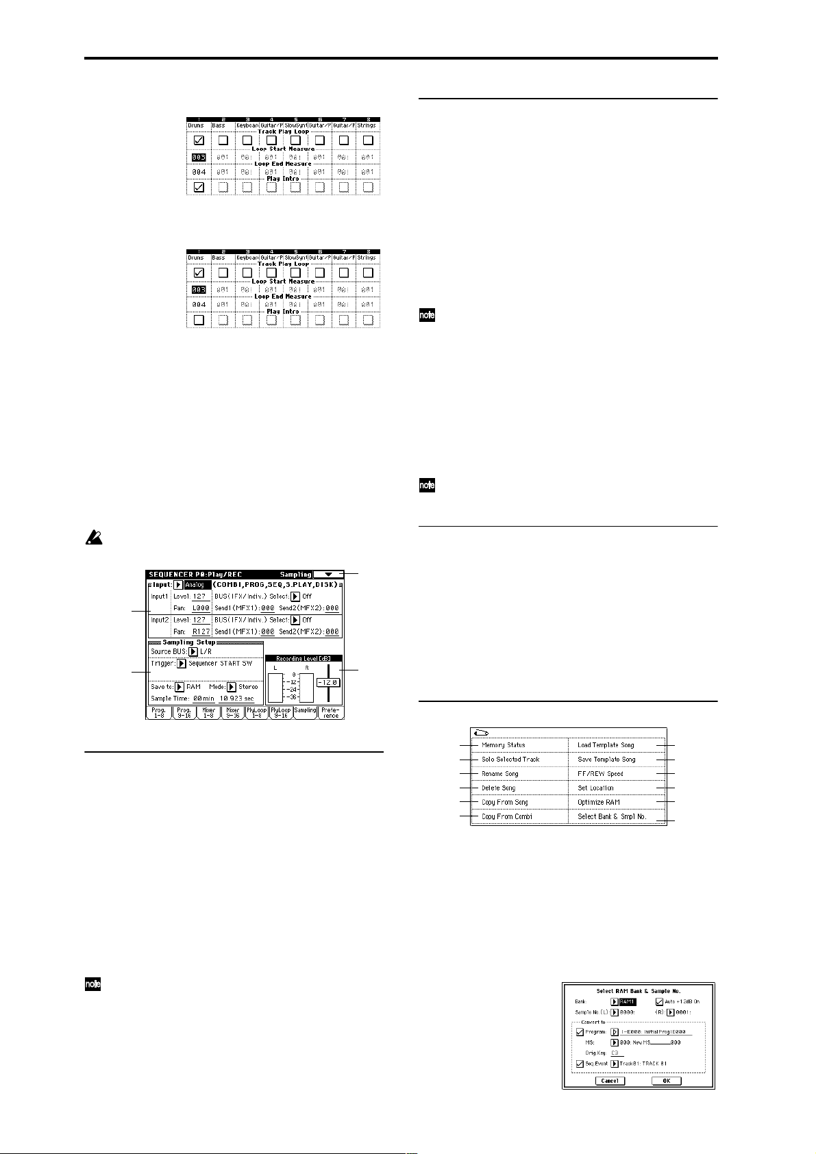
Example) When “Play Intro” is checked
Track 1 will loop as follows.
M001–M002–M003–M004–M003–M004–M003–M004…
When “Play Intro” is not checked
Track 1 will loop as follows.
M003–M004–M003–M004–M003–M004–M003–M004...
In this way, you can use “Track Play Loop” to make the real-
time recording process more efficient (☞BG p.50).
0–7: Sampling
Here you can adjust the settings for analog/digital audio
signal input (AUDIO INPUT, S/P DIF, EXB-mLAN) and the
settings for sampling in Sequencer mode. (☞p.49)
You can sample either an external audio signal, or a performance played on the TRITON STUDIO.
It is not possible to realtime-record a song or pattern
while sampling.
0–7
0–7a
0–7b
0–7c
0–7b: Sampling Setup
Source BUS [L/R, Indiv.1/2]
Save to [RAM, DISK]
Mode (Sample Mode) [L-Mono, R-Mono, Stereo]
Sample Time [min sec]
Make sampling-related settings for Sequencer mode. (☞Pro-
gram P0: 0–3)
T rigger [Sampling START SW, Note On,
Threshold, Sequencer START SW]
Specifies the trigger that will initiate sampling.
Sampling START SW: (☞Program P0: 0–3)
In Sequencer mode, the metronome count will operate
according to the Metronome Setup (0–8b) setting.
Note On: (☞Program P0: 0–3)
Threshold: Sampling will begin automatically when the
input level exceeds the specified “Level” value. (☞Sampling
P0: 0–7b)
Sequencer START SW: Press the SAMPLING [REC] key
and then the SAMPLING [START/STOP] key to enter sampling-standby mode. Then press the SEQUENCER [START/
STOP] key to begin sampling. Use this when you want to
resample the song playback.
The various Sampling Setup settings apply to the entire
Sequencer mode, not to individual songs.
0–7c: Recording Level [dB]
ADC OVERLOAD !!
Recording Level [–inf, –72.0...0.0...+18.0 dB]
Adjusts the signal level at the final stage of sampling in
Sequencer mode. (☞Sampling P0: 0–1d)
This setting defaults to –12 dB when you turn on the power.
At a setting of –12 dB, CLIP will not appear even if you play
the Song at its maximum level.
(☞Program P0: 0–3c “Recording Level”)
0–7a: Input (COMBI, PROG, SEQ, S.PLAY, DISK)
Input [Analog, S/P DIF, mLAN]
Input1:
Input2:
Level [0...127]
Pan [L000...C064...R127]
BUS(IFX/Indiv.) Select
[L/R, IFX1…5, 1, 2, 3, 4, 1/2, 3/4, Off]
Send1(MFX1), Send2(MFX2) [000...127]
Here you can specify the analog/digital audio input source,
and specify the input level, bus, and the send levels to the
master effects.
The various Input settings will apply to Combination,
Program, Sequencer, Song Play, and Disk modes.
(☞Global P0: 0–3a)
56
▼ 0–7: Page Menu Command
0–1A
0–1B
0–1C
0–1D
0–1E
0–1F
☞ Program P0: 0–3D: Select Directory
0–1G
0–1H
0–1I
0–1J
Program
0–3B
0–7A
0–7A: Select Bank & Smpl No.
Here you can specify the RAM bank and sample number
into which the sample will be written. You can also specify
whether the sample will be automatically converted into a
program after sampling. “Select Bank & Smpl No.” can be
selected if you have chosen RAM for “Save to.”
1 Choose “Select Bank & Smpl No.” to access the dialog
box.
Page 68

2 In “Bank,” specify the bank of sample memory (RAM)
into which sampling will be performed.
3 In “Sample No.,” choose a sample number where the
sampling will be performed. By default, this will be the
lowest-numbered of the vacant sample numbers. If you
select ----:---No Assign--- or a sample number that
already contains data, the sample will automatically be
sampled into the lowest-numbered vacant sample number. If you are sampling in stereo, “Sample No.(L)” and
“Sample No.(R)” will be created.
4 Set “Auto +12 dB On.”
On (checked): “+12 dB” (Sampling P2: 2–1c) will auto-
matically be turned on for samples you record. Samples
for which “+12 dB” is on will play back approximately
+12 dB louder than if this setting were off.
When you resample a performance in Program, Combination, or Sequencer modes, you should normally set
“Recording Level” to about –12.0 (dB) so that the record-
ing level will be as high as possible without clipping.
When you resample, the sound will be recorded at the
optimum level for sampled data, but the playback level
at playback will not be as loud as it was during the resampling process (if “+12 dB” (Sampling P2: 2–1c) is off). In
such cases, you can check the “Auto +12 dB On” check
box when you resample, so that “+12 dB” (Sampling P2:
2–1c) will automatically be on, making the sample play
back at the same level as when it was resampled.
In these modes, the power-on default settings are
“Recording Level” at –12.0 (dB) and “Auto +12 dB On.”
If you resample a performance in the respective mode
with these settings, the sample will play back at the same
level at which it was resampled.
If you want to monitor your performance in Program,
Combination, or Sequencer mode, while sampling only
the external audio signal from AUDIO INPUT etc. (with
the “Source BUS” Indiv.1/2 setting: 0–7b), we recom-
mend that you set “Recording Level” to about +0.0
(dB) and turn off “Auto +12 dB On” when you resam-
ple.
The “Auto +12 dB On” setting is made independently
for Program, Combination, Sequencer, and Sampling
modes.
5 “Convert to” lets you specify whether the sample will
automatically be converted to a program after sampling.
Y ou can also specify whether a note event will be cr eated
at the time of sampling.
If the “Program” check box is checked, the sample will
automatically be converted to a program. (☞Sampling
P0: 0–1a)
At the right, use “Program” and “MS” to specify the program number and multisample number of the program
that will be created.
“Orig.Key” (Sampling P0: 0–1b) specifies the location of
the original key. The multisample will be created with an
“Index” (Sampling P0: 0–1a) having this key as its “Top
Key” (Sampling P0: 0–1b). “Orig.Key” will increment
after sampling, so that the next sample will be assigned
to the next higher key.
If you check the “Seq.Event” check box, a note event will
automatically be created in the track specified by
“Track.” Note-on will occur at the location at which sampling began, and note-off will occur at the location at
which sampling ended. The note event will be created as
in “Recording Setup” Over Dub mode (i.e., it will be
added without erasing existing events). If you are sampling repeatedly without stopping the song playback, the
event(s) will be automatically created when you stop
song playback. The “Program Select” (0–1c/2c) of the
“Track” you created will automatically will automatically
change to the program you specified in “Program.”
“Seq.Event” is available only if “Program” has been
checked.
6 Press the OK button to apply the settings you made, or
press the Cancel button to discard any settings you
made after accessing the dialog box.
0–8: Preference
Here you can select the method of realtime recording, and
set the metronome.
0–1
0–1a
0–1b
0–8a
0–8b
0–8a: Recording Setup
Recording Mode [Over Write...Loop All Tracks]
Selects the method of realtime recording.
Refer to BG p.83 for the realtime recording.
Over Write
When recording for the first time, you will normally select
this method.
To begin recording, press the SEQUENCER [REC/WRITE]
key and then the SEQUENCER [START/STOP] key. To stop
recording, press the SEQUENCER [START/STOP] key once
again.
Be aware that when this method of recording is used to
record on a track that already contains data, any previously
existing data will be erased starting from the measure at
which you begin recording and from all subsequent measures.
Over Dub
Select this method when you wish to add data to a previously-recorded track.
To begin recording, press the SEQUENCER [REC/WRITE]
key and then the SEQUENCER [START/STOP] key. To stop
recording, press the SEQUENCER [START/STOP] key once
again.
The newly recorded data will be added to the previously
recorded data already residing in that track.
Manual Punch In
Select this method when you wish to use the SEQUENCER
[REC/WRITE] key or a foot switch to re-record selected portions of a previously-recorded track.
Press the SEQUENCER [START/STOP] key to playback the
song. When you reach the measure at which you wish to
begin re-writing the data, press the SEQUENCER [REC/
WRITE] key or the foot switch, and recording will begin.
When you are finished recording, press the SEQUENCER
[REC/WRITE] key or the foot switch once again, and
recording will end.
Sequencer
P0
P1 P2 P3 P4 P5 P6 P7 P8 P9
57
Page 69

Auto Punch In
Select this method when you wish to automatically rerecord selected portions of a previously-recorded track.
If you select Auto Punch In, the display will indicate “M***–
M*** (Auto Punch In Start Measure–Auto Punch In End Measure)” at the right, allowing you to specify the range of measures that will be rewritten.
Press the SEQUENCER [REC/WRITE] key and then the
SEQUENCER [START/STOP] key, and playback will occur
until the specified measure is reached. Then, recording will
occur only over the specified area (“Start Measure”–“End
Measure”), rewriting it with the newly recorded data.
M–M (Auto Punch In Start Measure – Auto Punch In
End Measure) [M001…M999 – M001…M999]
When “Recording Mode” is set to Auto Punch In, specify
the measures at which recording will start and end.
Loop All Tracks
Select this method when you wish to repeatedly record a
specified area of a track, and continue adding data. This is
suitable for creating drum patterns, etc.
If you select Loop All Tracks, the display will indicate
“M***–M*** (Loop Start Measure–Loop End Measure)” at
the right, allowing you to specify the range of measures that
will be recorded repeatedly.
Press the SEQUENCER [REC/WRITE] key and then the
SEQUENCER [START/STOP] key, and playback will occur
until the specified measure is reached. Then, recording will
occur repeatedly over the specified area (“Loop Start Measure”–“Loop End Measure”). Previously-recorded data will
remain, and the new data will be added. While recording,
you can check “Remove Data” to delete unwanted data.
If “Multi REC” is checked, this parameter will not be
available.
M–M (Loop Start Measure – Loop End Measure)
[M001…M999 – M001…M999]
Specifies the range of measures over which recording will
repeat when “Recording Mode” is set to Loop All Tracks.
Specify the range of measures in which recording will be
repeated.
Remove Data [Off, On]
Unwanted playback data can be removed while you record
using the Loop All Tracks setting. This is available when
“Recording Mode” is set to Loop All Tracks.
On (checked): You can delete unwanted musical data while
recording with Loop All Tracks. During recording, press the
key (note number) that corresponds to the musical data you
wish to delete. All occurrences of that note number will be
deleted for the interval that you continue holding down the
key. Controller data can also be erased in a similar way. For
example while you move and hold the joystick in the X (horizontal) direction, bender data will be erased. While you
apply pressure to the keyboard, after touch data will be
erased.
Also, you can press and hold down the SEQUENCER [REC/
WRITE] key to delete all musical data for as long as the key
is held.
If this is checked, the “PLAY/MUTE/REC” setting (0–1c/
2c) (button) of all tracks will be set simultaneously to REC.
For tracks that you do not want to record, press “PLAY/
MUTE/REC” (button) to select either PLAY or MUTE (the
setting will cycle in the order of PLAY→MUTE→REC).
This mode can also be used when you wish to playback a
connected multi-track sequencer, and record all of the MIDI
data it transmits in one pass into the TRITON STUDIO’s
sequencer (☞BG p.85).
Multiple channels of MIDI data can be received and simultaneously recorded onto multiple tracks.
In this case, tracks whose “PLAY/MUTE/REC” setting is
REC will record MIDI data whose channel matches their
own MIDI channel setting, regardless of the “Track Select”
(0–1a) setting.
In this case you will probably want to set “MIDI Clock”
(Global P1: 1–1a) to External MIDI or External mLAN, to
sync up with an external sequencer. However, changes in
tempo will not be recorded. (“Recording musical data from
an external device” ☞p.266)
Off (unchecked): Single track recording mode will be
selected. Recording will occur on the track selected by
“Track Select.”
This cannot be selected if “Recording Mode” is set to
Loop All Tracks.
0–8b: Metronome Setup
Here you can make metronome settings.
Sound [Only REC, REC & Play, Off]
Only REC: The metronome will sound only during recording.
REC & Play: The metronome will sound during recording
and playback.
Off: The metronome will not sound. However , the pre-count
will sound before recording begins.
This parameter can also be set from “Metronome Sound” (6–
1b).
BUS (Output) Select [L/R, L, R, 1, 2, 3, 4, 1/2, 3/4]
Selects the output destination of the metronome sound.
L/R, L, R: Output from OUTPUT (MAIN) L/Mono and/or
R.
1, 2, 3, 4, 1/2, 3/4: Output from OUTPUT (INDIVIDUAL) 1, 2,
3, 4 respectively.
Level [000…127]
Sets the volume of the metronome.
Precount [Measure] [0…2]
Specifies the pre-count that will occur before recording
begins.
With a setting of 0, recor ding will begin the instant you press
the SEQUENCER [START/STOP] key (after first pressing
the SEQUENCER [REC/WRITE] key).
Multi REC [Off, On]
On (checked): Multi-track recording mode will be selected.
Use this mode when you wish to simultaneously record
multiple tracks.
Use this when you want to realtime–record a performance
played by the arpeggiator on multiple tracks of differing
channels.
58
Page 70
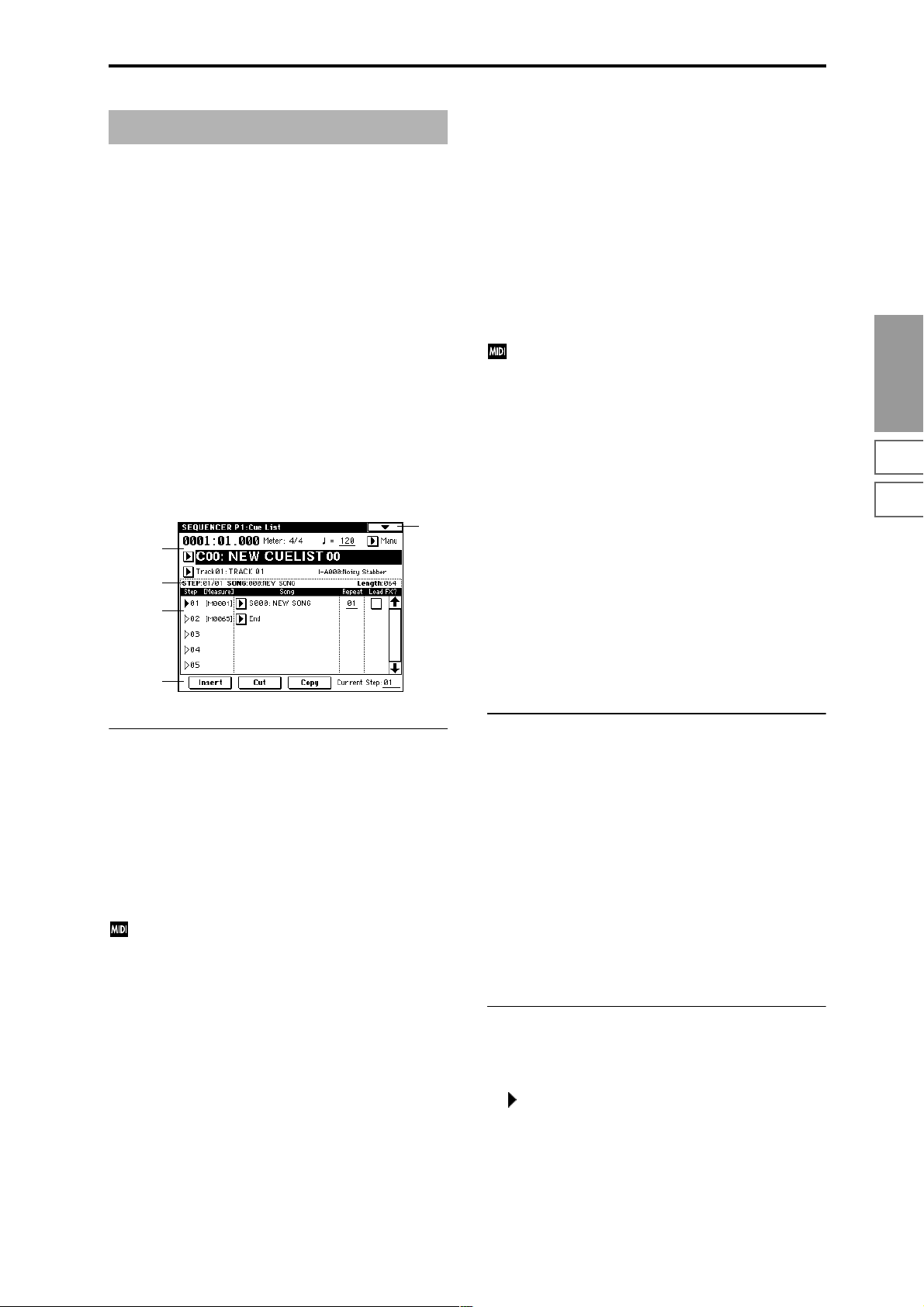
Sequencer P1: Cue List
1–1: Cue List
The cue list allows you to playback multiple songs in succession. You can specify a number of repetitions for each song.
The TRITON STUDIO allows you to create twenty cue lists.
In a single cue list you can freely connect up to 99 songs.
Each unit in a cue list is called a “step,” and you can specify
a song number and a repeat (number of repetitions) for each
step.
For example you could create each part of a song (intro, melody A, melody B, break, solo backing, ending etc.) as an
individual song, and use a cue list to play the intro twice,
melody A four times, melody B four times, the break twice,
melody A four times ... etc. to produce the entire song. In
cases when you wish to change the structure of the song,
this Cue List function can help you work more efficiently.
The page menu command “Convert to Song” (1–1D) lets
you convert the songs in a cue list into a single song.
For example you can use a cue list to create the backing, convert the cue list to a song, and then add solo phrases on
unused tracks.
1–1
1–1a
1–1b
1–1c
1–1d
Tempo Mode [Auto, Manu]
Auto: Playback will follow the tempo specified by each song
in the cue list. It will not be possible to change the “
(Tempo)” setting during playback.
Manu (Manual): Tempo specified in the song will be
ignored, and playback will use the tempo specified above
for “ (Tempo).”
Cue List Select [C00...C19: name]
Selects the cue list that you wish to play.
When using a cue list to play songs, you must first load the
necessary data into internal memory, either from media
(floppy disk etc.), or by a MIDI data dump from an external
sequencer.
When “MIDI Clock” (Global P1: 1–1a) is Internal,
selecting a cue list in this page will cause a Song Select
message (corresponding to the cue list number) and
Song Position Pointer message to be transmitted. When
“MIDI Clock” is External MIDI or External mLAN, a
Song Select message from the specified source will
switch cue lists.
Track Select [Track01...Track16: name]
Selects the track that you wish to play manually from the
keyboard along with the playback of the cue list.
While a cue list is playing, you can play along using the
track settings and musical data of the song selected by the
current “Step” (1–1c).
The track selected here can be specified independently for
each song in the cue list.
When you are playing back different songs in succession,
and want to play along using the same program on the keyboard, set “Track Select” (0–1a) to the same track and program for each step.
At the right you can view the program bank, program number, and name of the program selected for “Track Select.”
Sequencer
P0
P1 P2 P3 P4 P5 P6 P7 P8 P9
1–1a: Location, Meter, , Tempo Mode, Cue List
Select, Track Select
Location [0001:01.000…9999:16.191]
This displays the current location within the selected cue
list.
From the left, the numbers indicate the measure, beat, and
clock. Each can be set separately, and this will change the
current location within the cue list.
The range of the beat and clock will depend on the time signature of the corresponding song.
When “MIDI Clock” (Global P1: 1–1a) is Internal, a
Song Position Pointer message will be transmitted each
time you change the location within the cue list. If
“MIDI Clock” is set to External MIDI or External
mLAN, and “Receive Ext. Realtime Commands” (Glo-
bal P1: 1–1a) is turned on, receiving a Song Position
Pointer message from the specified source will cause
the location to change.
If the location exceeds the allowable data range of a
Song Position Pointer message, it will not be transmitted.
Meter (Time Signature) [1/4...16/16]
This displays the time signature of the currently-playing
song.
(Tempo) [040...240]
Specifies the tempo at which the song in the cue list will be
played (☞“0–1a: Tempo”).
1–1b: Selected Step Information
This shows information on the currently selected or playing
“Step.”
STEP (01...99/01...99)
The selected step number is shown at the left, and the total
number of steps (not including the last step) is shown at the
right.
SONG (000...199)
This shows the number and name of the song for the currently selected step.
Length (000...999)
This shows the number of measures in the song for the currently selected step.
1–1c: Step, Song, Repeat, Load FX?
Step [Measure] [01...100 (M0001...M9999)]
This displays the step number and its starting measure.
“Step” indicates each step number. The “Step” indicated by
the symbol is the currently-selected or currently-playing
step. This can be directly selected by “Song” (1–1c) or “Current Step” (1–1d). When stopped, pressing the SEQUENCER
[START/STOP] key will cause playback to begin from this
step.
“Measure” indicates the starting measure of each step. This
cannot be edited.
59
Page 71

Song (Cue Edit - Song)
[S000...S199: name/End, Continue to Step01]
S000...S199: Specifies a song for each step. This cannot be
edited during playback.
End and Continue to Step01 can be specified only for the
last step of the cue list.
End: Playback will stop at the last step of the cue list.
Continue to Step01: At the last step of the cue list, playback
will return to “Step” 01 and the cue list will continue playing endlessly. To stop, press the SEQUENCER [START/
STOP] key.
Repeat [01...64, FS]
Specifies the number of times that the song of this step will
be repeated.
FS: A foot switch connected to the rear panel can be used to
specify the point at which the song will stop repeating.
When you press the foot switch, that repetition of the song
will finish playing, and then playback will continue to the
next step. Set “Foot Switch Assign” (Global P2: 2–1a) to Cue
Repeat Control.
Load FX? (Cue Edit-Load Fx) [Off, On]
Specifies whether the effects specified by the song assigned
to each step will be used.
On (checked): The effect settings of the song specified for
the current step will be used. When playback moves to the
next step, the effect settings will also change.
Off (unchecked): The effect settings will not change.
Depending on the effect settings, a certain amount of
time may be required to switch effects. In this case,
playback will not be smooth from song to song.
If you want to transition smoothly from song to song
inside of a cue list, check “FX Load?” in “Step” 01. For
the remaining steps, do not check “FX Load?”
With these settings, the effects will be set before playback begins, so there will be no time lag to interrupt the
smooth transition between songs.
Although it is not possible to change the effect types in
the middle of a cue list, you can use the dynamic modulation function or MIDI control changes (effect control)
to apply reverb more deeply to certain songs, or raise
the LFO speed for other songs, etc.
When using a cue list to construct a song, we recommend this method. When you execute the “Convert to
Song” (1–1D) page menu command, the effect settings
of the “Step” 01 song will be specified at the beginning
of the song that is created by the conversion.
Even when “Load FX?” is not checked, there may be a
time lag in the transition from one song to the next,
depending on the musical data in the song. There may
also be cases in which the musical data at the transition
between songs does not play at the correct timing. To
fix this, you can edit the musical data of the song, or
convert the cue list to a single song. If you use “Convert
to Song” (1–1D) to convert the cue list to a song, there
will be no time lag at the transition, and the musical
data will play at the correct timing.
1–1d: Insert, Cut, Copy, Current Step
Insert
When you press the Insert button, the step data that was
temporarily saved in the buffer by the Copy button or Cut
button will be inserted at the “Current Step.” (If copy or cut
has not been executed, default data will be inserted.)
Cut
When you press the Cut button, the “Current Step” will be
cut, and its data will be saved temporarily in the buffer. If
you Insert immediately after you cut, the data will return
the state in which it was before you cut.
Copy
When you press the Copy button, the data of the “Current
Step” will be saved temporarily in the buffer.
Press the Insert button to insert the copied step into the
“Current Step.”
Current Step [01...100]
Selects the step that will be inserted, cut or copied.
If you wish to playback from a step in the middle of the cue
list, select the desired step here, and press the SEQUENCER
[START/STOP] key.
For details on creating and editing a cue list, refer to BG
p.90.
▼ 1–1: Page Menu Command
0–1A
1–1A
1–1B
1–1C
1–1D
1–1E
0–1I
0–1J
1–1A: Rename Cue List
This command renames the selected cue list. A name of up
to sixteen characters can be input. (☞BG p.57)
1–1B: Delete Cue List
This command deletes the currently selected cue list.
1 Select “Delete Cue List” to access the dialog box.
2 To execute the Delete Cue List command, press the OK
button. To cancel, press the Cancel button. When you
execute this command, the data of the currently selected
cue list will be deleted.
1–1C: Copy Cue List
This command copies the settings of another cue list to the
currently selected cue list.
1 Select “Copy Cue List” to access the dialog box.
60
2 In “From,” specify the copy source cue list.
3 To execute the Copy Cue List command, press the OK
button. To cancel, press the Cancel button.
When you execute, the setting data of the selected cue list
will be deleted, and replaced by the copy-source data.
Page 72

1–1D: Convert to Song (Convert Cue List to Song)
This command converts a cue list consisting of multiple
songs to a single song. Although it is not possible to record
additional tracks into a cue list, you can convert the cue list
to a song, and then record solos etc. onto open tracks.
Also, it will be necessary to convert a cue list to a song if you
wish to write it to a floppy disk as SMF data. During the
conversion, the track and effect settings of the song specified
for “Step” 01 will be copied to the beginning of the resulting
song, and all track and effect settings of subsequent songs
will use the settings of the song for “Step” 01.
1 Select the cue list (C00–19) that you want to convert to a
song.
2 Select “Convert to Song” to access the dialog box.
3 In “To Song,” specify the conversion destination song
number.
If you select a new song, a confirmation dialog box will
appear.
Press the OK button to create a new song, into which the
cue list will be converted.
4 Press the OK button to execute the conversion, or press
the Cancel button to cancel without executing.
If you selected a song that already contains settings and
performance data, executing this command will erase the
data of that song and replace it with the data that was
converted from the cue list. Use this command with caution.
After executing this command, you can press the [COMPARE] key to return to the state prior to execution.
The “Convert to Song” command converts a cue list to a
song as described below.
• Song/Track parameter settings for “Step” 01
Song/Track parameters will use the settings of the
“Step” 01 song.
The MIDI channel of each track will be according to the
settings of the “Step” 01 song. If “Step” 02 and following songs have different settings, it may not be possible
to convert the playback result of the cue list into a song.
As far as possible, try to keep the MIDI channel assignments consistent between songs that you intend to use
as part of a play list that will be converted into a song.
The following track parameters will not be reflected in
the conversion. As with the MIDI channels, we recommend that you keep these settings consistent between all
songs in the cue list.
SOLO ON/OFF, Status, MIDI Channel, Bank Select (When Status =
EX2), Force OSC Mode, OSC Select, Delay, Use Programs Scale,
MIDI Filter, Key Zone, Velocity Zone
• Converting Song/Track parameters into track events
Second and subsequent repeats of the “Step” 01 song,
and the settings of “Step” 02 and following songs will all
be converted into track events (musical data). The following data will be converted.
Track1–16 Program Select, Pan, Volume, Portamento,
Detune, Bend Range
Master T rac k T empo , Meter
If “Pan” (0–3a/4a) is RDN, it will be converted to C064.
If “Portamento” (2–3a/4a) is PRG, or if “Bend Range”
(2–5a/6a)is PRG or a negative value, these will not be
reflected in the conversion.
“Detune” (2–5a/6a) will be divided into RPN Fine T uning and Coarse Tuning, and converted into events. For
example if the “Detune” setting of +600, Fine Tuning
will be 00 and Coarse T uning will be 6. Fine Tuning will
modify the playback pitch (Detune). Coarse T uning will
change the notes that are played back (Transpose). For
this reason with some programs such as drum programs, the playback result produced by a cue list may
not be reproduced when the cue list is converted into a
song.
•“PLAY/MUTE”
(P0: Program T01–08, 09–16 “PLAY/MUTE/REC”)
The “PLAY/MUTE” track parameters will be reflected in
the song. “SOLO ON/OFF” will not be reflected.
•“Track Play Loop” (P0: PlyLoop 1–8, 9–16 page)
If “Track Play Loop” is on, the area from “Loop Start” to
“Loop End” will be expanded as far as the last measure
in the master track.
Example)
If “Track Play Loop” is M005–M008, and the master track
contains 10 measures, the data will be expanded from the
beginning of the track as M005, 6, 7, 8, M005, 6, 7, 8,
M005, 6.
•“Play Intro” (P0: PlyLoop 1–8, 9–16 page)
If “Track Play Loop” is on, the data will be developed
according to the Play Loop setting until the last measure
of the master track.
If “Play Intro” is checked, the data from the beginning of
the track until “Loop End” will be developed, and then
the data from “Loop Start” until “Loop End” will be
developed until the last measure of the master track.
For example if “T rack Play Loop” is M005–M008 and the
master track ends at measure 10, checking “Play Intro”
will cause the data to be developed from the beginning of
the track as M001, 2, 3, 4, 5, 6, 7, 8, M005, 6, 7, 8, M005, 6.
If “Play Intro” is not checked, refer to the example in
“Track Play Loop.”
• Patterns
Patterns in the “Step” 01 song will be copied as patterns
of the converted song.
If there is a second or subsequent repeat for “Step” 01, or
if the tracks of “Step” 02 and subsequent songs contain
patterns, they will be expanded into track events (musical data).
•“Transpose”
If the “Transpose” (2–5a/6a) of the tracks in “Step” 02
and subsequent songs differ from the settings of the
“Step” 01 song, the note numbers of the note data will be
shifted.
Example)
If “Step” 01 “Transpose” = +1 and “Step” 02 “Trans-
pose” –1, the actual note numbers of the “Step” 02 track
note data will be shifted downward by 2.
•“Repeat” FS (Foot Switch) → “Repeat” 1
If “Repeat” is set to FS (Foot Switch), it will be converted
as “Repeat” 1.
When you execute “Convert to Song” to convert a cue
list to a song, the repeat settings within the cue list and
the pattern and track play loop settings of the songs
used by the cue list will all be converted into events
such as note data. For this reason, the amount of data
will increase significantly, and in some cases there may
not be enough internal memory to perform the conversion. In particular if the cue list uses long songs, or if
Sequencer
P0
P1 P2 P3 P4 P5 P6 P7 P8 P9
61
Page 73

numerous repeats have been specified, or if many patterns are used by the songs, you should try executing
the “Convert to Song” command from time to time as
you create the cue list, in order to verify the amount of
memory that will be required for the conversion.
A cue list that is longer than 999 measures cannot be
converted into a song.
1–1E: Copy Song
This command copies a portion (a number of measures) of
the song specified by “Step,” and makes it into a song. This
is convenient when you want to modify the structure or
development of the songs in a cue list.
For example if you have an eight-measure song and want to
repeat measures 5–8, you can use this command to create a
four-measure song out of that portion. Then you can assign
the resulting song to a step in a cue list, and repeat it.
1 In “Current Step,” or “Song” select the desired step.
2 Select “Copy Song” to access the dialog box.
3 In “From Measure,” specify the first measure in the copy
source song. In “To End of Measure,” specify the last
measure.
4 In “To Song,” specify the song into which the data will
be converted. If you select a new song, a dialog box will
ask you for confirmation. Press the OK button to create a
new song and copy the data to that song. If you select an
existing song that already contains settings and/or musical data, executing this command will erase the data of
that song and rewrite it with the data from the copy
source. Before you execute, be sure that you will not be
losing important data.
5 If you check “Replace to original Song in Cue List” and
execute this command, the “Current Step” song will be
replaced by the newly created song. If you execute with-
out checking this box, the newly created song can be
selected later for the desired step of the cue list.
6 To execute the Copy Song operation, press the OK but-
ton. To cancel, press the Cancel button.
Sequencer P2: Trk Param
2–1: MIDI Ch 1–8 (MIDI Ch T01–08) 2–2: MIDI Ch 9–16 (MIDI Ch T09–16)
Here you can make MIDI-related settings for each track.
0–1
0–1a
0–1b
0–3a
2–1a
LSB
MSB
2–1(2)a: Status, MIDI Channel, Bank Select
Status [INT, Off, BTH, EXT, EX2]
This sets the status of MIDI and the internal tone generator
for each track.
INT: When the musical data recorded in the track is played
back, or when you use “Track Select” (0–1a) to select a track
that is set to INT and play the keyboard and operate the
controllers, the internal tone generator of the TRITON STUDIO will sound, and MIDI data will not be transmitted to an
external device.
Off: The program will not sound, nor will MIDI data be
transmitted.
BTH: The operation of both INT and EXT will be performed. When the musical data recorded in the track is
played back, or when you select a track that is set to BTH
and play the keyboard and operate the controllers, the internal tone generator of the TRITON STUDIO will sound, and
at the same time MIDI data will also be transmitted to an
external device.
EXT: When the musical data recorded in the track is played
back, or when you select a track that is set to EXT and play
the keyboard and operate the controllers, MIDI data will be
transmitted to an external device, but the internal tone generator of the TRITON STUDIO will not sound.
When you select another song or return to the beginning of
the song, the program change, volume, panpot, portamento,
sends 1 and 2, post IFX pan, and post IFX sends 1 and 2 of
each track set to EXT will be transmitted via MIDI.
EX2: “Bank Select (When Status=EX2)” will be enabled.
Instead of the INT-A–EXB-G bank numbers that can be
selected on the TRITON STUDIO, the bank number you
specify here will be transmitted. In other respects this is the
same as EXT.
MIDI data is transmitted and received on the MIDI
channel that is specified separately for each track by
“MIDI Channel.”
62
Recorded data
Keyboard and controller
operations Received data
Status Internal tone
generator
INT ●✕●—
EXT, EX2 ✕●✕—
BTH ●●●—
MIDI OUT Internal tone
generator
MIDI OUT
Page 74

MIDI Channel [01…16]
Specifies the MIDI channel that the track will use to transmit
and receive musical data. The MIDI channel you specify
here will be the receive channel when “Status” is INT, the
transmit channel when it is EXT or EX2, and the receive/
transmit channel when it is BTH. Tracks set to INT which
have the same MIDI channel will sound and be controlled
identically when they receive MIDI data or data from the
sequencer tracks.
Bank Select (When Status=EX2) [000:000...127:127]
When “Status” is set to EX2, this sets the bank number that
will be transmitted.
The left value is the MSB, and the right value is the LSB.
When “Status” is other than EX2, this setting has no effect.
2–3: OSC 1–8 (OSC T01–08) 2–4: OSC 9–16 (OSC T09–16)
These parameters specify how each track will be sounded.
0–1
0–1a
0–1b
0–3a
2–3a
CC#65 of 127 and CC#05 of 1–127 will be transmitted.
If this is set to PRG, nothing will be transmitted.
This data is transmitted and received on the MIDI channel specified for each track by “MIDI Channel” (2–1a/
2a).
2–5: Pitch 1–8 (Pitch T01–08) 2–6: Pitch 9–16 (Pitch T09–16)
Here you can make pitch-related settings for each track.
2–5
0–1a
0–1b
0–3a
2–5a
2–5(6)a: Transpose, Detune, Bend Range
Transpose [–24...+24]
Adjusts the pitch of each track in semitone steps.
12 steps are one octave.
Sequencer
P0
P1 P2 P3 P4 P5 P6 P7 P8 P9
2–3(4)a: Force OSC Mode, OSC Select, Portamento
Force OSC Mode [PRG, Poly, MN, LGT]
Selects the Voice Assign Mode (Program P1: 1–1b) of the program selected for each track 1–16 (☞Combination P2: 2–2a).
OSC Select [BTH, OS1, OS2]
Specifies the “Oscillator Mode” of the program selected for
each track 1–16. If the “Oscillator Mode” is Double, you can
use this setting to make only one or the other oscillator
sound (☞Combination P2: 2–2a).
Portamento [PRG, Off, 001...127]
Specifies the portamento effect for each track 1–16 (☞Combination P2: 2–2a).
The portamento setting you make here will be used
when the song is played or recorded from the beginning. If you change the setting while recording, it will
be recorded as part of the musical data. (However if
you set this to PRG, it will not be recorded.) You can
change this setting during playback. However if you
come to any Portamento On/Off data or Portamento
Time data that was recorded, the settings will change
accordingly.
When the track whose “Status” (2–1a/2a) is INT or
BTH, MIDI control change CC#5 (Portamento Time)
and CC#65 (Portamento Switch) can be received to control this and change the setting. (If the setting is PRG,
CC#05 Portamento Time will not be received.)
When you switch songs or return to the beginning of
the song, tracks whose “Status” is BTH, EXT, or EX2
will transmit this setting via MIDI. If this is Off, CC#65
with a value of 0 will be transmitted. If this is 001–127, a
Detune (BPM Adj. in Page Menu) [–1200... +1200]
Adjusts the pitch of each track in one-cent steps from the
normal pitch.
0: Normal pitch.
You can use the “Detune BPM Adjust” (2–5A) page menu
command to make a calculation in BPM units and set
Detune automatically.
“Transpose” and “Detune” settings do not affect the
note data that is transmitted via MIDI. “Transpose” and
“Detune” are controlled by received MIDI RPN messages. The “Oscillator Mode” (Program P1:1–1a) of the
programs selected for tracks 1–16 will be controlled as
follows. These messages will be received on the MIDI
channel that is specified for each track by “MIDI Channel” (2–1a/2a).
• If “Oscillator Mode” is Single or Double, MIDI RPN
Coarse Tune messages can be received to control and
change the “Transpose” setting, and Fine Tune
messages to control and change the “Detune” setting.
• If “Oscillator Mode” is Drums, MIDI RPN Coarse
Tune and Fine Tune messages can be received to
control and change the “Detune” setting. The range of
control will be ±1 octave when Coarse Tune and Fine
Tune are added.
Bend Range [PRG, –24...+24]
Specifies the range of pitch change in semitone steps that
will occur when the pitch bender is operated.
PRG: The pitch range specified by the program will be used.
–24–+24: Regardless of the setting of the program, pitch
bending will use the range you specify here.
This setting can be controlled and changed by received
MIDI RPN Pitch Bend Range messages. (These messages will not be received if the setting is PRG.)
63
Page 75

▼ 2–5: Page Menu Command
0–1A
0–1B
0–1C
0–1D
0–1E
0–1F
0–1G
0–1H
0–1I
0–1J
2–5A
2–5A: Detune BPM Adjust
When the program selected for a track uses a phrase,
rhythm loop multisample (or sample that was created to
match a specific BPM in Sampling mode or loaded from disk
in Disk mode) you can use this command to change the
BPM of the phrase or rhythm. The BPM can be adjusted by
modifying the pitch. This command is available when the
“Detune” setting of that track is selected. When you execute
this command, the selected “Detune” value will be adjusted.
For the procedure, refer to “Detune BPM Adjust” (Combination P2: 2–3A).
2–7: Other 1–8 (Other T01–08) 2–8: Other 9–16 (Other T09–16)
Here you can make additional settings for each track.
Key [C…B]
Selects the tonic key of the selected scale (☞“Key” Program
P1: 1–1c).
Random [0…7]
As this value is increased, an increasingly random deviation will be added to the pitch at each note-on (☞“Random”
Program P1: 1–1c).
0–1
0–1a
0–1b
0–3a
2–7a
2–7(8)a: Delay [ms], Use Program’s Scale, Scale
Delay [ms] [0000...5000, KeyOff]
Specifies a delay time from when a track receives a note-on
until it actually sounds.
KeyOff: The sound will begin when note-off occurs. In this
case, the sound will continue indefinitely unless the amp EG
Sustain Level of the program is other than 0. This setting is
useful for simulating harpsichord sounds.
Normally you will leave this at 0.
Use Program’s Scale [Off, On]
Each track can use the scale that is specified for the program
by “Scale.”
On (checked): The scale that is saved with the program will
be used.
Off (unchecked): The scale specified here by Scale will be
used.
Scale:
Specifies the scale that will be used for the song.
Type (Song's Scale)
[Equal Temperament...User Octave Scale15]
Selects the type of scale (☞“Type” Program P1: 1–1c).
64
Page 76
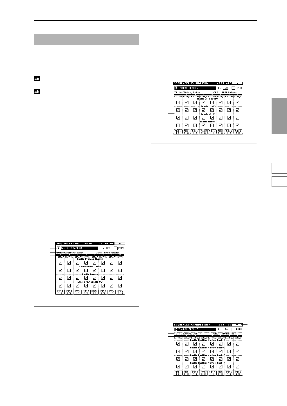
Sequencer P3: MIDI Filter
Here you can select whether or not to apply filtering to the
MIDI data received by tracks 1–16. For example even if two
tracks are receiving the same MIDI channels, one can be
made to respond to damper pedal activity while the other
does not.
These MIDI filter settings have no effect on the MIDI
messages that have already been recorded.
These settings affect the MIDI messages that are transmitted when you adjust program, pan, volume, portamento and send 1/2 parameters of a track whose
“Status” (2–1a/2a) is set to BTH, EXT, or EX2.
On (checked): Reception of MIDI data is enabled. Tracks
whose “Status” (2–1a/2a) is INT or BTH will receive these
types of MIDI messages on their respective channels. The
type of effects that are checked will be applied to the program of each track when the TRITON STUDIO’s controllers
are operated or when MIDI data is received. (The effect
dynamic modulation function is not affected by these settings.) Settings that regulate MIDI transmission/reception
of the TRITON STUDIO itself are made in MIDI Filter (Global P1: 1–1b).
If the user-assignable controllers that can be filtered in the
MIDI 3 and MIDI 4 pages are set to MIDI control changes,
filtering will be performed for these control changes. In this
case, any control change filtering that is being performed in
the MIDI 1 and MIDI 2 pages will be given priority. Furthermore, if the same control change is assigned to multiple controllers for which there are filter settings in the MIDI 3 and 4
pages, checking any one of these will enable that control
change.
Off (Unchecked): Reception of MIDI data is disabled.
Enable Portamento SW [Off, On]
Specifies whether or not MIDI control message CC#65 Portamento On/Off will be received.
3–3: MIDI 2 1–8 (MIDI Filter –2 T01–08) 3–4: MIDI 2 9–16 (MIDI Filter –2 T09–16)
0–1a
0–1b
0–3a
3–3a
3–3(4)a: Enable JS X as AMS, Enable JS+Y,
Enable JS-Y, Enable Ribbon
Enable JS X as AMS [Off, On]
Allow incoming MIDI pitch bend messages (the X-axis of
the TRITON STUDIO’s joystick) to control the AMS
(☞p.242) that is specified for JS X. (This is not a reception filter for MIDI pitch bend messages.)
Enable JS+Y [Off, On]
Specifies whether or not MIDI control message CC#1 (the +Y
axis of the TRITON STUDIO’s joystick, or assigned to B-
mode of the REALTIME CONTROL knobs [1]–[4]) will be
received.
0–1
Sequencer
P0
P1 P2 P3 P4 P5 P6 P7 P8 P9
3–1: MIDI 1 1–8 (MIDI Filter –1 T01–08) 3–2: MIDI 1 9–16 (MIDI Filter –1 T09–16)
0–1a
0–1b
0–3a
3–1a
3–1(2)a:
Enable Program Change, Enable After Touch,
Enable Damper, Enable Portamento SW
Enable Program Change [Off, On]
Specifies whether or not MIDI program change messages
will be received.
Enable After Touch [Off, On]
Specifies whether or not MIDI after touch messages will be
received.
0–1
Enable JS-Y [Off, On]
Specifies whether or not MIDI control message CC#2 (the –Y
axis of the TRITON STUDIO’s joystick, or assigned to B-mode
of the REALTIME CONTROL knobs [1]–[4]) will be received.
Enable Ribbon [Off, On]
Specifies whether or not MIDI control message CC#16 (the
TRITON STUDIO’s ribbon controller, or assigned to B-mode
of the REALTIME CONTROL knobs [1]–[4]) will be received.
3–5: MIDI 3 1–8 (MIDI Filter –3 T01–08) 3–6: MIDI 3 9–16 (MIDI Filter –3 T09–16)
Here you can specify whether the A and B-mode effects of
the REALTIME CONTROL knobs [1]–[4] will be transmitted
and received. The A-mode MIDI controller messages for
each knob are fixed. The B-mode messages can be set in P4:
Zone/Ctrl, Controller page.
0–1a
0–1b
0–3a
3–5a
0–1
Enable Damper [Off, On]
Specifies whether or not MIDI control message CC#64 Hold
(damper pedal) will be received.
65
Page 77

3–5(6)a: Enable Realtime Control Knob 1...4
Enable Realtime Control Knob 1 [Off, On]
Specifies whether or not the A-mode MIDI control message
CC#74 (the TRITON STUDIO’s low pass filter cutoff fre-
quency) and the B-mode MIDI control message will be
received.
Enable Realtime Control Knob 2 [Off, On]
Specifies whether or not the A-mode MIDI control message
CC#71 (the TRITON STUDIO’s low pass filter resonance or
high pass filter cutoff frequency) and the B-mode MIDI control message will be received.
Enable Realtime Control Knob 3 [Off, On]
Specifies whether or not the A-mode MIDI control message
CC#79 (the TRITON STUDIO’s filter EG intensity) and the
B-mode MIDI control message will be received.
Enable Realtime Control Knob 4 [Off, On]
Specifies whether or not the A-mode MIDI control message
CC#72 (the release time of the TRITON STUDIO’s filter and
amplifier EG’s) and the B-mode MIDI control message will
be received.
3–7: MIDI 4 1–8 (MIDI Filter –4 T01–08)
Sequencer P4: Zone/Ctrl
4–1: Key Z 1–8 (Key Zone T01–08) 4–2: Key Z 9–16 (Key Zone T09–16)
Here you can specify the range of keys that will be sounded
by each track.
T op/Bottom Key settings specify the range of notes that will
be sounded by tracks 1–16, and Top/Bottom Slope settings
specify the range from the top/bottom key until the original
volume is reached.
These settings do not affect MIDI transmission/reception. All note data that is received will be recorded into
the internal sequencer, and all note data from the internal sequencer or from the keyboard will be transmitted.
0–1
4–1a
0–1a
0–1b
0–3a
4–1b
3–8: MIDI 4 9–16 (MIDI Filter –4 T09–16)
0–1a
0–1b
0–3a
3–7a
3–7(8)a: Enable SW1, Enable SW2,
Enable Foot Pedal/Switch,
Enable Other Control Change
Enable SW1, Enable SW2 [Off, On]
Specifies whether or not the effect of the [SW1] and [SW2]
keys will be received.
The function of these keys can be set in P4: Zone/Ctrl, Controller page.
This is valid when the switches are set to SW1 Mod.:CC#80,
SW2 Mod.:CC#81 or Porta.SW:CC#65.
Enable Foot Pedal/Switch [Off, On]
Specifies whether or not the effect of the ASSIGNABLE
PEDAL/SWITCH will be received. The function of this
switch is set in Global P2. This is valid when the switch is set
to a MIDI control change.
Enable Other Control Change [Off, On]
Specifies whether or not MIDI controller messages other
than those included in MIDI Filter 1–4 will be received.
0–1
4–1a: Zone Map
This shows the range of notes and velocities that will be
sounded by each track 1–16.
The note and velocity ranges are shown as lines, and the
slope area within the range is shown in gray.
Bottom Slope
Bottom Key Top Key
Track 1
Key zone
display
Track 16
C-1 G9
Top Slope
Velocity zone
display
1 . . . 16
Tra ck
Top Velocity
Top Slope
Bottom Slope
Bottom Velocity
4–1(2)b: Top Key, Top Slope, Bottom Slope,
Bottom Key
Top Key [C–1...G9]
Specifies the top key (upper limit) that will be sounded by
each track 1–16.
Top Slope [00...72]
Specifies the key range (12 is one octave) from the top key
until the original volume is reached.
Bottom Slope [00...72]
Specifies the key range (12 is one octave) from the bottom
key until the original volume is reached.
Bottom Key [C–1...G9]
Specifies the bottom key (lower limit) that will be sounded
by each track 1–16.
You can also enter a value for these parameters by playing a note while you hold down the [ENTER] key.
66
Page 78

4–3: Vel Z 1–8 (Vel Zone T01–08) 4–4: Vel Z 9–16 (Vel Zone T09–16)
Here you can set the Top/Bottom Velocity parameters to
specify the range of velocities that will be sounded by tracks
1–16, and Top/Bottom Slope specify the range over which
the volume will be adjusted.
These settings do not affect MIDI transmission/reception. All note data that is received will be recorded into
the internal sequencer, and all note data from the internal sequencer or from the keyboard will be transmitted.
0–1
4–1a
0–1a
0–1b
0–3a
4–3a
4–7: Controller (Controller Setup)
Here you can set the functions that the [SW1] key, [SW2] key,
and the B-mode functions that the REALTIME CONTROL
knobs [1]–[4] will have in Sequencer mode.
When these switches or knobs are operated during
recording, the MIDI messages that you assign here will
be recorded.
0–1
0–1a
0–1b
4–7a
4–7b
Sequencer
4–3(4)a: Top Velocity, Top Slope, Bottom Slope,
Bottom Velocity
Top Velocity [1…127]
Specifies the maximum velocity that will be sounded by
each track 1–16.
Top Slope [0…120]
Specifies the range of values over which the volume will be
adjusted from the top velocity until the original volume is
reached.
Bottom Slope [0…120]
Specifies the range of values over which the volume will be
adjusted from the bottom velocity until the original volume
is reached.
Bottom Velocity [1…127]
Specifies the minimum velocity that will be sounded by
each track 1–16.
Y ou can also enter a value for these parameters by playing a note while you hold down the [ENTER] key.
4–5: MOSS 1–8 (MOSS T01–08) 4–6: MOSS 9–16 (MOSS T09–16)
This page is displayed when the EXB-MOSS option has been
installed. For details refer to the owner’s manual included
with the EXB-MOSS.
4–7a: Panel Switch Assign
Assigns functions to the [SW1] and [SW2] keys (“SW1, SW2
Assign List” ☞p.249).
Since the functions assigned to these switches by the program assigned to each track will no longer be valid, you can
make new assignments here.
SW1 (SW1 Assign) [Off, ..., After Touch Lock]
SW1 Mode [Toggle, Momentary]
SW2 (SW2 Assign) [Off, ..., After Touch Lock]
SW2 Mode [Toggle, Momentary]
☞ Program P1: 1–4a
4–7b: Realtime Control Knobs B-Assign
Here you can set the B-mode functions (mainly various control changes) that the REALTIME CONTROL knobs [1]–[4]
will have in Sequencer mode (“Realtime Control Knobs B–
Assign List” ☞p.250). The functions you specify here will
operate when you rotate the REALTIME CONTROL knobs
[1]–[4] in B-mode.
Since the functions assigned to these knobs by the program
assigned to each track will no longer be valid, you can make
new assignments here.
Knob 1-B [Off, ..., MIDI CC#95]
Knob 2-B [Off, ..., MIDI CC#95]
Knob 3-B [Off, ..., MIDI CC#95]
Knob 4-B [Off, ..., MIDI CC#95]
☞ Program P1: 1–4b
P0
P1 P2 P3 P4 P5 P6 P7 P8 P9
67
Page 79

Sequencer P5: Track Edit
5–1: Track Edit
Here you can make settings for the currently selected track,
edit previously-recorded performance data, and perform
step recording.
When you wish to edit musical data or perform step recording, specify the desired area. Then select the appropriate
page menu command.
5–1
0–1a
5–1b
0–1b
5–1a
5–1b
5–1a: Track data Map
This area shows the presence or absence of performance
data, and indicates the range of editing, etc. (The track
selected by “Track Select” will be highlighted.)
Track1
▼ 5–1: Page Menu Command
5–1G
0–1A
5–1A
5–1B
5–1C
5–1D
5–1E
5–1F
5–1H
5–1I
5–1J
5–1K
5–1L
5–1N
5–1O
5–1P
0–1I
0–1J
5–1Q
5–1M
5–1A: Step Recording
Step recording allows you to specify the length and velocity
of each note numerically, and to input the pitches from the
keyboard. You can use the Rest button and Tie button to
input a rest or tie.
If you use step recording to input data into a track that
already contains sequence data, all data will be erased
from the “From Measure” and subsequent measures. If
after inputting, you decide to revert to the prior data,
use the Compare function.
To input data with a continuously-changing value such as
pitch bend, it is best to use “Create Ctrl Data” (5–1L). To
input individual data events such as program changes, use
“Event Edit” (5–1B).
1 Use “Track Select” to select the track into which you
wish to input data, and use “From Measure” (5–1b) to
specify the measure at which you wish to begin input.
2 When you select “Step Recording,” the following dialog
box will appear.
Track16
From Measure
Performance data exists No performance data Pattern is used
To End of Measure
Master Track
5–1b: Track Select, From Measure, To End of
Measure
Track Select [Track01...Track16, Master Track]
Selects the track that you wish to edit (or copy from) or
record.
If you wish to select all tracks, it is not necessary to specify
them here. Check the “All Tracks” item within the dialog
box of the page menu command.
Master T rack: Edit the tempo or time signatur e of the master
track.
From Measure [001…999]
To End of Measure [001…999]
Specifies the range of measures that you wish to edit (or
copy from) or step-record.
Use “From Measure” to specify the starting measure, and
“To End of Measure” to specify the ending measure.
Time signature
Length
(beats, clocks)
measure (beat, clock)
Note numberLocation within the
Velocity
3 In “Meter,” set the time signature.
This will show the time signature that has already been
set for the measure.
If you change the time signature setting, the time signature data of the measures you record will change, and all
tracks will change to the time signature you specified.
4 In “Step Time,” specify the length (in terms of a note
value) of the basic interval at which you will input data.
From the popup menu at the left, select the note length in
a range of (whole note) through (32nd note).
If you want the selected note value to be a dotted note or
a triplet, use the popup menu at the right to select a dot “.
(Dot)” or triplet “3 (Triplet).” To use the unmodified
value of the selected note, choose “– (Normal).”
68
Page 80

The following table shows the number of clocks represented by each “Step Time” selection.
(the LED will go dark) to cancel the pause mode and
resume input.
8 When you are finished with step recording, press the
Done button. If you press the [COMPARE] key, you will
return to the condition of before you began step recording.
3
5 In “Note Duration,” specify the length that the note will
actually be held, relative to the “Step Time.” In general,
100% will be tenuto, 85% will be normal, and 50% will be
staccato.
6 Use “Note Velocity” to specify the velocity value (key-
board playing strength) of the note data. With the
[PAUSE] key pressed, you can hold down the [ENTER]
key and play a note on the keyboard to specify the velocity value. If you set this to Key, the actual velocity at
which you played the key will be input.
7 Input the note events described below by playing notes
on the keyboard or by pressing the buttons in the lower
part of the dialog box.
• Inputting notes
When you press a key on the keyboard, that note number
will be input as a note of the length specified in
When you press a chord on the keyboard, those note
numbers will be input as chords of the length specified in
4. Since each of the note numbers you press before
releasing all of the keys will be input at the same location, the notes will be input as a chord even if they are
actually played at different times.
Each time you press and release the keyboard, the location will advance by the length specified in
• Inputting rests
Press the Rest button to input a rest of the length speci-
4.
fied in
• Inputting a tie
If you press the Tie button without pressing the keyboard, the previously-input note will be tied, and lengthened by the amount specified in
If you press the Tie button while holding down a note,
the note you are playing will be tied, and lengthened by
the amount specified in
You can even input notes as shown in the following diagram.
4.
4.
4.
4.
5–1B: Event Edit
Here you can edit individual events of music data that were
input.
1 Use “Track Select” to select the track that you wish to
edit, and use “From Measure” (5–1b) field to specify the
measure at which you wish to begin editing.
If you selected Track01–16 in “Track Select,” selecting
this command will open the Set Event Filters dialog box.
If you selected Master Track in “Track Select,” this dia-
log box will not appear.
In the Set Event Filters dialog box you can select the
types of events (musical data) that will appear and can be
edited in the event edit window.
For “Note” you can set “Bottom” and “Top” to specify
the range of notes available for editing. These settings
can also be entered by holding down the [ENTER] key
and pressing a key. Normally you will leave these set at
C–1 and G9.
“Control Change” lets you specify the control change
number. Normally you will leave this set at ALL.
You can also check various other events (“Pitch Bend,”
“Program Change,” “After Touch,” and “Poly After
Touch”).
2 Press the OK button to open the Event Edit dialog box.
Measure
Sequencer
P0
P1 P2 P3 P4 P5 P6 P7 P8 P9
On
Step Time =
Off
Release E (continue holding C)
Step Time =
Press E and C
• Deleting a note or rest
To delete a note or rest, press the StepBack button. The
location will move backward by the amount specified in
4, and the data in that interval will be deleted.
• Auditioning the next note before input
If you wish to make sure of the next note before you actually input it, press the [PAUSE] key (the LED will light).
Now when you press a key, you will hear sound but the
note will not be input. Press the [PAUSE] key once again
Step Time =
Tie
ON
Press G
Index no. Location within the
3 In the upper part of the dialog box, “Measure” and
“Index” show the measure that you are editing and the
events of the index numbers within the measure.
You can touch the scroll bar located at the right to move
to the event that you wish to edit.
4 Select the event that you wish to edit, and use the VALUE
controller etc. to modify its value(s).
• By modifying the value of the “BT” (Beat. Tick) location
within the measure, you can move the event within the
measure.
• You can edit each event by modifying its data value(s).
When you select a note event, it will sound.
5 You can press the buttons located at the bottom of the
dialog box to edit events as follows.
• Inserting an event
Select the location “BT” at which you wish to insert an
event, and press the Insert button to insert an event.
measure (beat, clock)
Event data
69
Page 81

• Deleting an event
Select the event that you wish to delete, and press the
Cut button to delete the event.
• Moving an event
Y ou can use the Cut button and Insert button to move an
event (by “cut and paste”).
Use the Cut button to delete the event that you wish to
move, then use the Insert button to insert it at the
desired location.
You can also move an event by modifying its “BT” value.
• Copying an event
Select the event that you wish to copy, and press the
Copy button. Then select the copy destination and press
the Insert button to insert the event at that location.
6 When you are finished event editing, press the Done but-
ton. If you press the [COMPARE] key you will return the
data to the condition in which it was before you began
event editing.
The following table shows the types of musical data that can
be edited by “Event Edit” and the range of their values.
BAR (displayed only)
(Measure line)
C–1...G9 *
(Note data)
PAFT
(Polyphonic after
touch)
CTRL
(Control change)
PROG
(Program change)
AFTT
(After T ouch)
BEND
(Pitch bend)
2
V: 1...127 *
(Velocity)
C–1...G9
(Note number)
C: 0...101
(Control change number)
Bank: I-A...I-F,
000...127,
G, g(1)...g(9) g(d), - - -,
E–A...E-G
(Program bank)
0...127
(value)
–8192...+8191
(value)
2
Meter: 1/4...16/16 *
(Time signature)
L: 000.000...15984.000
(Length: beats, clocks)
0...127
(Value)
0...127
(Value)
P: 0...127,
1...128 (G, g(1)...g(d))
(Program number)
1
*1 Be aware that because the time signature is recorded
in the master track, modifying it from any track will
affect the same measure of all tracks, causing them
all to be played in the modified time signature.
*2 Note data and velocity values can also be entered by
holding down the [ENTER] key and playing a note
on the keyboard.
Pattern numbers will be displayed in locations in which a
pattern has been “put” (placed). At the end of the track there
will be an indication of End of Track.
5–1C: Erase Track
This command erases the data from the specified track.
However, it is not possible to erase the master track by itself.
1 In “Track Select,” select the track that you wish to erase.
2 Select “Erase Track” to access the dialog box.
5–1D: Copy Track
This command copies musical data from the copy source
track to the specified track.
Be aware that when you execute the Copy Track command,
any track data that was in the copy destination track will be
erased.
1 Select “Copy Track” to access the dialog box.
2 In “From,” select the copy source track. In “To,” select
the copy destination. (By default, “From” will be the
track you selected in “Track Select.”)
3 To execute the Copy Track command, press the OK but-
ton. To cancel, press the Cancel button.
5–1E: Bounce Track
This command combines the musical data of the bounce
source and bounce destination tracks, and places the combined data in the bound destination. All musical data in the
bounce source will be erased.
If MIDI control data existed in the bounce source track and
bounce destination track, unexpected results may occur during playback after the bounce command is executed. To prevent this from happening, use “Event Edit” (5–1B) or “Erase
Control Data” (5–1M) to edit the MIDI control data of the
two tracks before you use Bounce Track.
1 Select “Bounce Track” to access the dialog box.
2 In “From,” specify the bounce source track. In “To” spec-
ify the bounce destination track. (By default, “From” will
be the track you selected in “Track Select.”)
3 To execute the Bounce Track command, press the OK
button. To cancel, press the Cancel button.
5–1F: Erase Measure
This command erases the specified type(s) of musical data
from the specified range of measures. The Erase Measure
command can also be used to remove only a specific type of
data. Unlike the Delete Measure command, executing the
Erase Measure command does not cause the subsequent
measures of musical data to be moved forward.
1 Use “Track Select” to select a track.
2 Select “Erase Measure” to access the dialog box.
If you check “All Tracks,” the musical data of all tracks
will be erased.
3 To execute the Erase Track command, press the OK but-
ton. To cancel, press the Cancel button.
70
3 In “From Measure” select the first measure to be erased,
and in “To End of Measure” select the last measure to be
erased. (By default, “From Measure” and “To End of
Measure” will be set to the range that you specified in the
Track Edit page.)
4 In “Kind,” specify the type of data that will be erased.
All will erase all types of data from the track, Note will
erase note data, Control Change will erase control
change data, After Touch will erase both channel pres-
sure and polyphonic key pressure data, Pitch Bend will
erase pitch bend data, and Program Change will erase
program change data.
Page 82

5 If you check “All Tracks,” the specified type of data will
be erased from all tracks.
6 To execute the Erase Measure command, press the OK
button. To cancel, press the Cancel button.
Example: If measures 2–3 are erased, measures 2–3 will be blank.
Before Erase
After Erase
21 543
21 543
Example: When measures 2 and 3 (3/4 time) of track 2 are deleted, the measures that were
at 4 and 5 are moved forward, and their time signature will change to 3/4.
1 (4/4) 3 (3/4) 5 (4/4)2 (3/4) 4 (4/4)
Before Delete
After Delete
Track 1
1 (4/4) 3 (3/4) 5 (4/4)2 (3/4) 4 (4/4)
Track 2
Track 2
Track 1
2 (3/4)1 (4/4) 3 (3/4)
2 (3/4)1 (4/4) 3 (3/4) 4 (4/4) 5 (4/4)
No data
If control data extends across measures that were
erased and measures that were not erased, only the
data within the range being erased will be erased. However if note data extends across two or more measures,
deleting any of the intervening measures will delete
that note data from the following measures as well.
Note data can also be erased using “Shift/Erase Note”
(5–1O). Use this command when you wish to erase a
specific range of notes, or to erase notes from a specific
“Beat.Tick.”
Control Change data can also be erased using “Erase
Control Data” (5–1M). Use this when you wish to erase
a specific type of control change, or to erase control
change data from a specific “Beat.Tick” range.
5–1G: Delete Measure
This command deletes the specified measures.
When the Delete Measure command is executed, the musical data following the deleted measures will be moved
towards the begining of the sequence.
1 Use “Track Select” to select the track.
2 Select “Delete Measure” to access the dialog box.
If in
4 you check “All Tracks” and execute this opera-
tion, the specified measures of musical data will be
deleted from all tracks including the master track, and
the time signature and tempo will also move forward
by the number of measures that were deleted.
If control data extends across a line between measures
that were deleted and measures that were not deleted,
only the data within the range being deleted will be
erased. However if note data extends across two or
more measures, deleting any of the intervening measures will delete that note data from the following measures as well.
5–1H: Insert Measure
This command inserts the specified number of measures
into the specified track. When you execute the Insert Measure command, the musical data following the insert location will be moved backward.
If musical data is inserted into a range of measure across
which note data has been tied, a note-off will be created
immediately before the inserted measure, and the subsequent portion of the note will be deleted.
1 In “Track Select,” specify the track into which you wish
to insert.
2 Select “Insert Measure” to access the dialog box.
Sequencer
P0
P1 P2 P3 P4 P5 P6 P7 P8 P9
3 In “From Measure” select the first measure that you wish
to delete, and in “To End of Measure” select the last mea-
sure that you wish to delete. (By default, “From Measure” and “T o End of Measur e” will be the range that you
specified in the Track Edit page.)
4 If you wish to delete musical data from all tracks includ-
ing the master track, check “All Tracks.”
If this is not checked, data will be deleted only from the
track that was selected by “Track Select.”
5 To execute the Delete Measure command, press the OK
button. To cancel, press the Cancel button.
Example: When measures 3–5 are deleted, measures 6–8 are moved forward.
Before
Delete
After
Delete
1 2 3 4 5 6
21
If in
4 you uncheck “All Tracks” and execute this oper-
543
7 8
ation, the measures will not be deleted from the master
track. Time signature and tempo data will remain
unchanged, and the time signature and tempo of the
measures that were moved forward as a result of the
Delete operation will change.
3 In “At Measure,” specify the measure location at which
the data will be inserted. (The measure you specified in
Track Edit page “From Measure” will be set as a default.)
4 In “Length,” specify the number of measures that will be
inserted.
5 In “Meter,” specify the time signature of the measures
that will be inserted.
If you want the inserted measures to match the existing
time signature, specify **/**. With any setting other than
**/**, the time signature of the inserted measures will
change, and the specified time signature will apply to all
tracks for those measures.
6 If you wish to insert measures into all tracks including
the master track, check “All Tracks.” The musical data
following the inserted measures will playback in the
same way it did before the measures were inserted.
If “All Tracks” is unchecked, the measures will be
inserted only into the specified track. At this time, the
musical data following the inserted location will be
moved toward the end of the sequence by the number of
measures that were inserted. However, the time signature and tempo recorded in the master track and will not
change.
7 To execute the Insert Measure command, press the OK
button. To cancel, press the Cancel button.
71
Page 83

Time signature = **/**
Track 1
Before Insert
After Insert
Before Insert
After Insert
1 (4/4) 2 (4/4) 4 (5/4) 5 (2/4)3 (3/4)
1 (4/4) 2 (4/4) 4 (5/4) 5 (2/4)3 (3/4)
Track 2
Insert two measures
1 (4/4) 2 (4/4)
Track 2
Track 1
1 (4/4) 2 (4/4) 4 (5/4) 5 (2/4)3 (3/4)
Measures 4 and 5 will use the previously specified
time signature.
1 (4/4) 2 (4/4) 4 (5/4) 5 (2/4)3 (3/4)
Track 1
1 (4/4) 2 (4/4) 4 (5/4) 5 (2/4)3 (3/4)
Track 2
Insert two measures
Track 2
1 (4/4) 2 (7/8) 4 (5/4) 5 (2/4)3 (7/8)
Track 1
Measures 2 and 3 will be 7/8, and measures 4 and 5
will be the previously specified time signature.
3 (3/4)
Time signature = 7/8
5 (2/4)4 (5/4)
5 (2/4)4 (5/4)1 (4/4) 2 (7/8) 3 (7/8)
5–1I: Repeat Measure
This command repeatedly inserts the specified measures for
the specified number of times. When you execute the Repeat
Measure command, the measures will be inserted following
the measure specified by “To End of Measure,” and musical
data following the inserted data will be moved backward. It
is convenient to use this command when you have a song
that you playback with “Track Play Loop” (0–5a/6a) turned
on, and wish to expand it into musical data.
1 Use “Track Select” to select the track whose measures
you wish to repeat.
2 Select “Repeat Measure” to access the dialog box.
5–1J: Copy Measure
This command copies the measures of musical data specified as the “From” source to the begining of the measure
specified as the “To” location.
When you execute the Copy Measure command, the existing track data at the copy destination will be rewritten.
1 Select the copy source song.
2 Select “Copy Measure” to access the dialog box.
3 In From: “Track,” select the copy source track. (By
default, this will be the track you selected in “Track
Select.”)
If you check “All Tracks,” the musical data of all tracks
including the master track will be copied.
4 In “From Measure” and “To End of Measure,” specify
the range of copy source measures. (By default, “From
Measure” and “T o End of Measur e” will be the range that
you specified in the Track Edit page.)
5 In “To: Song,” specify the copy destination song. In
“Track” (when “All Tracks” is unchecked) specify the
copy destination track. In “Measure,” specify the first
measure where the copied measures will be inserted.
6 To execute the Copy Measure operation, press the OK
button. To cancel, press the Cancel button.
Example: When you copy measures 5–7 of track 1 to the third measure of track 2,
measures 3–5 of track 2 will be rewritten.
Track 1
(source)
Track 2
(destination)
2 (4/4)1 (4/4) 5 (3/4)4 (3/4)3 (4/4) 6 (3/4) 7 (4/4)
2 (4/4)1 (4/4) 5 (3/4)4 (3/4)3 (4/4) 6 (3/4) 7 (4/4)
3 In “From Measure” and “To End of Measure,” specify
the range of measures that will be repeated. (By default,
“From Measure” and “To End of Measure” will be set to
the range you specified in the Track Edit page.)
4 In “Times,” specify the number of repetitions. For exam-
ple if you set “From Measure” to 001, “To End of Mea-
sure” to 004, and “Times” to 2, the musical data of
measures 1–4 will be inserted into measures 5–8. The
result will be that measures 1–4 will be played twice.
5 If you wish to repeat the musical data of all tracks includ-
ing the master track, check “All Tracks.”
6 To execute the Repeat Measure command, press the OK
button. To cancel, press the Cancel button.
If you execute the Repeat Measure operation on measures 1–4 with “Time” = 2,
measures 1–4 will be inserted into measures 5–8.
Before
Repeat
Measure
After
Repeat
Measure
Track 1
Track 1
1 2
1 2
3 4
3 4
5 6
1 2
3 4
5 6
5–1K: Move Measure
This command moves measures of musical data to a specified destination. When you execute the Move Measure command, musical data following the move source will be
moved forward according to the number of measures
moved, and musical data following the move destination
will be moved backward correspondingly.
1 Select “Move Measure” to access the dialog box.
2 In From: “Track,” select the move source track. (By
default, this will be the track you selected in “Track
Select.”)
If you check “All Tracks,” musical data of all tracks
including the master track will be moved.
3 In “From Measure” and “To End of Measure,” specify
the range of measures that will be moved. (By default,
“From Measure” and “To End of Measure” will be the
range that you specified in the Track Edit page.)
4 In “To: Track” (if “All Tracks” is unchecked), specify the
move destination track. In “Measure,” specify the first
measure of the move destination.
5 To execute the Move Measure command, press the OK
button. To cancel, press the Cancel button.
72
Page 84

5–1L: Create Ctrl Data (Create Control Data)
This command gradually varies continuous-type data (e.g.,
control change, after touch, pitch bend, tempo) in the specified area.
1 In “Track Select,” select the track on which you wish to
perform the Create Control Data command.
If you wish to modify tempo data, select Master Track as
the track. In this case, the step
to “Tempo.”
2 Select “Create Ctrl Data” to access the dialog box.
3 Specify the range into which the control data will be
inserted.
In “From Measure” and “To End of Measure” specify
the measures, and in “Beat.Tick” specify the beat and
clock. (By default, “From Measure” and “To End of Measure” will be set to the range you specified in the Track
Edit page.)
4 “Kind” to the type of musical data (event) that you wish
to create.
Control change: Control change data will be inserted. In
this case, use “#” to specify the control change number.
After Touch: Aftertouch data will be inserted.
Pitch Bend: Pitch bend data will be inserted.
5 In “Start Value,” select the starting value of the control
data. In “End Value,” select the ending value of the con-
trol data. By default, the “Start Value” will be set to the
value of the existing data at the start location. If you wish
to create control data that changes smoothly from the
starting location, you can leave the “Start Value”
unchanged, and set only the “End Value.”
6 To execute the Create Control Data command, press the
OK button. To cancel, press the Cancel button.
Example: The controller is aftertouch. Starting location is 3:48, ending location is 4:24,
and end value is set to 100. This will cause the aftertouch value to begin
changing from 3:48, and reach a value of 100 at 4:24.
After touch
127
100
0
3:00 3:24 3:48 3:72 4:00 4:24 4:48
Start location End location
When you execute Create Control Data, a large amount
of sequencer memory will be consumed. For this reason
it may not be possible to execute this command if there
is a limited amount of memory remaining. In such
cases, first use “Quantize” (5–1N) to quantize the data
and remove unnecessary control data. Alternatively,
you could quantize the data that was inserted by the
Create Control Data command.
4 item “Kind” will be set
End Value
Previous data
Start Value
default value
Location
5–1M: Erase Ctrl Data (Erase Control Data)
This command erases data such as control changes, after
touch, pitch bend, or tempo in the specified range.
1 In “Track Select,” select the track from which you wish
to erase control data.
If you wish to erase tempo data, select Master Track. In
this case, the “Kind” item in step
4 will be Tempo.
2 Select “Erase Ctrl Data” to access the dialog box.
3 Specify the range from which you wish to erase control
data.
In “From Measure” to “To End of Measure” specify the
measures, and in “Beat.Tick” specify the beat and clock.
(By default, “From Measure” and “To End of Measure”
will be the range that was specified in the Track Edit
page.)
4 “Kind” to the type of musical data (event) that you wish
to erase.
Control change: Control change data will be erased. In
this case, use “#” to specify the control change number.
After Touch: Aftertouch data will be erased.
Pitch Bend: Pitch bend data will be erased.
5 To execute the Erase Control Data command, press the
OK button. To cancel, press the Cancel button.
If you wish to erase all control change data from specified measures, you can also use “Erase Measure” (5–1F)
and set “Kind” to Control Change. However, this Erase
Control Data command allows you to specify the range
using “Beat.Tick,” and also to erase only specific types
of control change data.
5–1N: Quantize
This command corrects the timing of musical data that
already exists in the sequencer . When you execute the Quantize operation, the musical data will be affected as follows:
• When you execute Quantize on note data, the timing of
the note-on will be corrected, but the length (duration of
the note) will not be affected.
• If the Quantize resolution is set to Hi, the timing will be
adjusted to units of the base resolution (/192), so note
data will not be affected. However, continuous
controller data such as joystick or after touch which
occupies a large amount of memory will be processed so
that two or more data events of an identical type existing
at a single interval of the timing resolution will be
combined into a single event, thus conserving memory.
Similarly, two or more data events of an identical type
existing at the identical timing will be combined into one,
also conserving memory.
1 In “Track Select,” specify the track.
2 Select “Quantize” to access the dialog box.
Sequencer
P0
P1 P2 P3 P4 P5 P6 P7 P8 P9
3 Specify the range that will be quantized.
73
Page 85
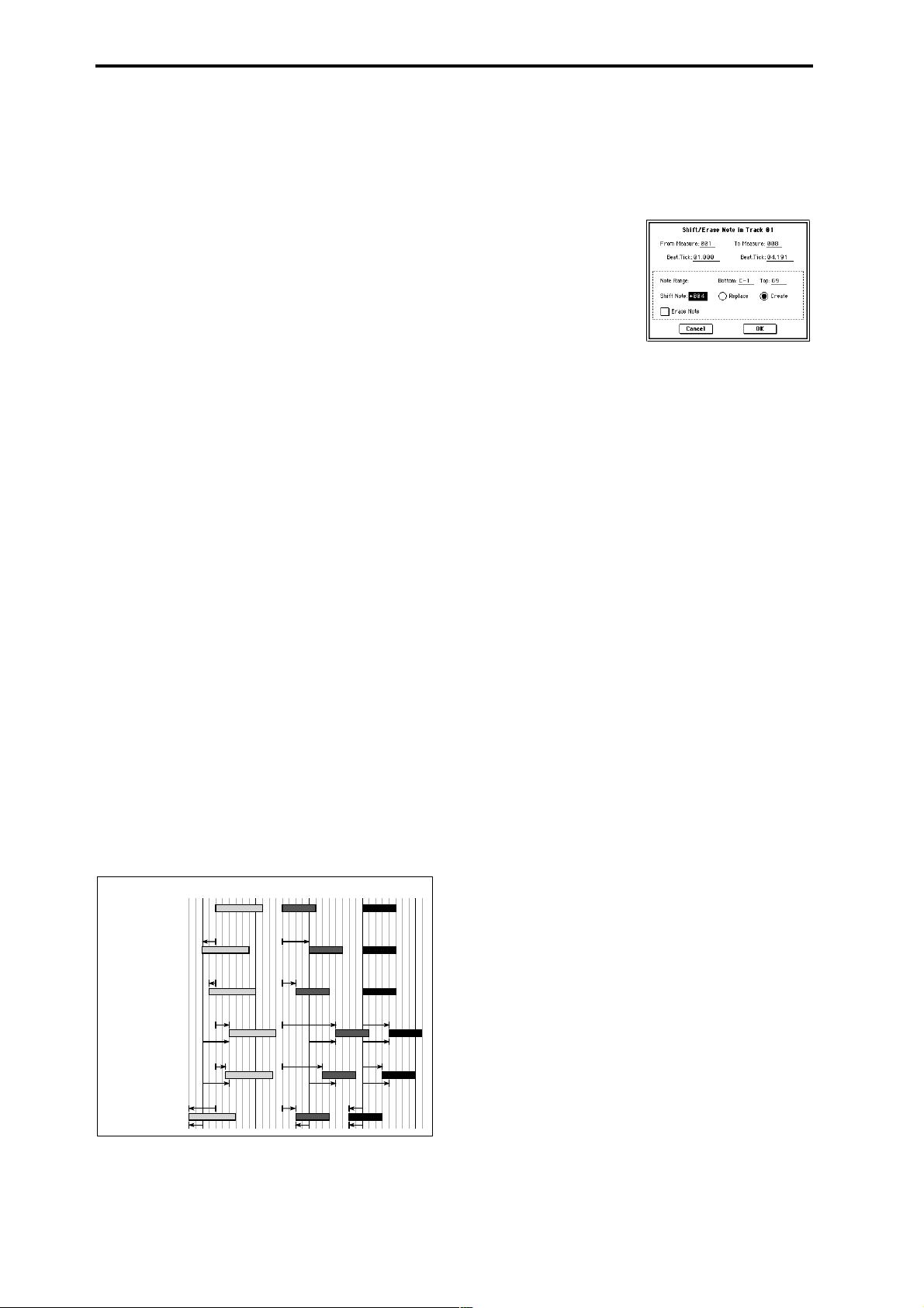
In “From Measure” and “To End of Measure,” specify
the measures. In “Beat.Tick” specify the beat and clock.
(By default, “From Measure” and “To End of Measure”
will be the range that you specified in the Track Edit
page.)
4 In “Kind,” select the type of musical data (events) that
you wish to quantize.
All: Quantization will be applied to all performance data.
Note: Quantization will be applied only to note data. Use
“Bottom” and “Top” to specify the range of notes. “Bottom” specifies the lowest note that will be affected, and
“Top” specifies the highest note. You can use this when
you want to quantize only a specific note or notes (for
example, just the snare sounds of a drum track). If you
want to quantize all notes, set these parameters C–1 and
G9 respectively. These note settings can also be input by
holding down the [Enter] key and playing a note on the
keyboard.
Control Change: Quantization will be applied to control
changes. If you want to quantize only a specific control
change, specify the number (“No.”). If you want to quantize all control changes, select All.
After Touch: Quantize both Channel Pressure and Polyphonic Key Pressure messages.
Pitch Bend: Pitch bend data will be quantized.
Program Change: Program change data will be quan-
tized.
5 In “Resolution,” specify the timing resolution to which
the data will be corrected.
By setting a lower resolution you can save more memory,
but the timing of the playback may not be acceptable.
6 In “Offset,” specify the number of clock ticks by which
the data will be moved forward or backward relative to
the standard timing. A setting of 96 will be , and 48 will
be . Positive (+) settings will adjust the data forward,
and negative (–) settings will adjust the data backward.
This allows you to simulate “pushing” or “dragging” the
beat.
7 In “Intensity,” specify the degree of sensitivity to which
the timing will be corrected; i.e., how close to the locations specified by
5 and 6 the data will be moved.
With a setting of 0, no correction will take place. With a
setting of 100, the data will be moved all the way to the
timing intervals specified by
5 and 6.
8 To execute the Quantize command, press the OK button.
To cancel, press the Cancel button.
* By varying the “Offset” and “Intensity” settings you can
create quantize effects such as the following.
Original
100%
Quantize Resolution =
Offset = 0, Intensity = 100%
Quantize Resolution =
Offset = 0, Intensity = 50%
Quantize Resolution =
Offset = +48, Intensity = 100%
Quantize Resolution =
Offset = +48, Intensity = 75%
Quantize Resolution =
Offset = –24, Intensity = 100%
100%
50% 50%
50%
100%
100%
+48
+48
75%
75%
+48+48
100%
100%
–24
100%
100%
50%
100%
100% 100%
+48 +48
+48 +48
75%
75% 75%
+48
+48
100% 100%
100% 100%
–24
100%
75%
+48
+48
–24
5–1O: Shift/Erase Note
This command shifts (moves) or erases the specified note
numbers in a specified track and range of measures.
1 In “Track Select,” select the track on which you wish to
execute the Shift/Erase Note command.
2 Select “Shift/Erase Note” to access the dialog box.
3 Specify the range in which you wish to shift or erase note
numbers.
In “From Measure” and “To End of Measure,” specify
the measures. In “Beat.Tick,” specify the beat and clock.
(By default, “From Measure” and “To End of Measure”
will be the range that you specified in the Track Edit
page.)
4 Specify the range of notes that you wish to shift or erase.
“Note Range: Bottom” specifies the lower limit, and
“Top” specifies the upper limit. If you wish to edit all
notes, set “Bottom” to C–1 and “Top” to G9. These settings can also be made by holding down the [ENTER]
key as you play a note.
• Shifting notes
5 In “Shift Note,” specify the amount by which you wish
to move the note.
The amount of shift is set in semitone steps over a range
of –127–+127. +1 will shift the note a semitone upward.
6 Select either “Replace” to move the note numbers, or
“Create” to generate additional notes.
For example if you are editing a track that uses a drum
program, you can use “Replace” to exchange the current
snare sound for a different snare sound assigned to a different key, or use “Create” to add a sound effect at a different note # to the snare sound. Alternatively, you can
use “Create” to add an octave doubling to an existing
guitar phrase, etc.
7 To execute the Shift Note command, press the OK but-
ton. To cancel, press the Cancel button.
• Erasing notes
5 Check “Erase Note.”
If you wish to erase all note data in the specified range of
measures, you can also use the “Erase Measure” command (5–1F) and set “Kind” to Note. However, this
Shift/Erase Note command lets you specify the
“Beat.Tick” range, and to erase only specific ranges of
note data.
6 To execute the Erase Note command, press the OK but-
ton. To cancel, press the Cancel button.
74
Page 86

5–1P: Modify Velocity
This command modifies the velocity values of notes in the
specified area so that they will change over time according
to a selected curve.
1 In “Track Select,” specify the track whose velocity will
be modified.
2 Select “Modify Velocity” to access the dialog box.
3 Specify the range in which note velocity will be modified.
“From Measure” and “To End of Measure” specify the
measure, and “Beat.Tick” specify the beat and clock. (By
default, “From Measure” and “To End of Measure” will
be set to the range that you specified in the Track Edit
page.)
4 Specify the range of notes that will be affected by the
Modify Velocity command. Note Range “Bottom” is the
lower limit, and “Top” is the upper limit. If you wish to
edit all notes, set “Bottom” to C–1 and “Top” to G9.
These settings can also be made by holding down the
[ENTER] key as you play a note on the keyboard.
5 In “Velocity Start Value” specify the value at which the
velocity data will start, and in “End Value” specify the
final velocity value. These settings can also be made by
holding down the [ENTER] key as you play a note on the
keyboard.
6 In “Intensity,” specify the degree to which the velocity
data will be adjusted toward the curve you specify in
With a setting of 0 [%], the velocity will not change. With
a setting of 100 [%], the velocity will be exactly as
described by the curve.
7 “Curve”* lets you select from six types of curve to specify
how the velocity will change over time.
8 To execute the Modify Velocity operation, press the OK
button. To cancel, press the Cancel button.
* The six curves are as follows.
7.
5–1Q: Set Song Length
This command changes the length of the specified song.
When it is executed, the length of the master track will
change, and the number of measures played will change.
1 Select “Set Song Length” to access the dialog box.
2 In “Length,” specify the length of the song.
3 To execute the Set Song Length command, press the OK
button. To cancel without executing, press the Cancel
button.
Be aware that if you shorten the song, data will also be
deleted from the tracks other than the master track.
5–2: Track Name
Here you can assign a name to each track.
5–1
0–1a
5–1b
0–1b
5–2a
5–2a: Track Name
Track Name [TRACK 01...TRACK 16]
Press the text edit button to access the dialog box, and input
the desired name. Up to 16 characters may be used. (☞BG
p.53, 57)
Sequencer
P0
P1 P2 P3 P4 P5 P6 P7 P8 P9
For a Start Velocity of 1 and End Velocity of 127
Velocity
Velocity
127
127
1
Start
Measure
1
Start
Measure
Curve 1
Curve 4
End
Measure
End
Measure
Velocity
Velocity
127
127
1
Start
Measure
1
Start
Measure
Curve 2
Curve 5
End
Measure
End
Measure
127
Velocity
127
Velocity
1
Start
Measure
1
Start
Measure
Curve 3
Rndm
RANDOM
End
Measure
End
Measure
75
Page 87

Sequencer P6: Pattern/RPPR
On the TRITON STUDIO you can use preset patterns P000–
149, and user patterns U00–99. One song can contain up to
one hundred user patterns. Preset patterns suitable for use
in a drum track are provided in memory, and can be selected
from any song.
Preset patterns cannot be edited, but you may copy a preset
pattern to a user pattern, and edit.
User patterns can be created by realtime recording (including recording that uses the arpeggiator), step recording, the
Get From Track command (obtaining data from a track), or
the Copy Pattern command (copying from another pattern)
(☞BG p.86).
These patterns can be assigned to each key by the RPPR
(Realtime Pattern Play/Recording) function and played by
pressing a single key, and the resulting performance can be
recorded on the sequencer (☞RPPR Setup page).
Pattern (Pattern Bank) [Preset, User]
Selects the type of pattern.
If Preset is selected, it will not be possible to record. You will
be able to select and execute the “Copy Pattern,” “Bounce
Pattern,” “Put to Track,” and “Copy to Track” page menu
commands.
Pattern Select [P000...149, U00...U99]
Selects a pattern. User patterns can be renamed in the Pattern Name page.
(Tempo) [040...240, EXT]
Specifies the playback tempo of the pattern. (☞0–1a).
Metronome Sound [Only REC, REC & Play, Off]
Specifies whether the metronome will sound during recording or playback. (☞0–8b, “Sound,” “Metronome Setup”)
Reso (Resolution) [Hi, 3 … ]
Specifies how the timing of the data being recorded into the
pattern will be corrected. (☞0–1a “Reso (Resolution).”)
6–1: Pattern Edit
Here you can record a pattern, edit it, and assign it to a track
in a song.
6–1
6–1a
6–1b
6–1c
6–1a: Location, Song Select, Track Select
Location [01...99]
Displays the current measure location of the selected pattern.
Song Select [000...199: name]
Selects a song.
The user pattern will be created in the song you select.
Track Select [Track01...Track16, Master Track]
Selects the track that will be used to record/play the pattern
data. The pattern data will be recorded/played using the
settings of the track you select. The area at the right displays
the program bank, number, and name for the selected track.
6–1b: Pattern, Pattern Select, Tempo, Metronome
Sound, Reso, Remove Data
If you wish to record pattern data, use “Pattern” and “Pattern Select” to select a user pattern and pattern number.
Next, use the “Pattern Parameter” page menu command to
set the number of measures in the pattern and its time signature. Then you can perform realtime recording in the Pattern
Edit page, or step recording by using the “Step Recording
(Loop Type)” page menu command. Finally, use page menu
commands as desired to perform event editing or other
types of editing.
Remove Data [Off, On]
On (checked): Unwanted performance data can be
removed during pattern recording. The procedure is the
same as explained in “Remove Data” of Loop All Tracks.
(☞0–8a)
6–1c: USED IN SONG TRACK, USED IN RPPR
USED IN SONG TRACK
This area indicates the song tracks in which the selected pattern is used.
USED IN RPPR
This area indicates the RPPR in which the selected pattern is
used. The assigned key and the specified track are shown.
How to record a user pattern
1 Use “Song Select” to select the song in which you want to
create a user pattern.
2 Use “Track Select” to select the sound that you will
record.
The pattern you record will sound according to your
choice in “Track Select.”
3 Use “Pattern Bank” and “Pattern Select” to select User
pattern and the desired pattern number.
4 Select the page menu command “Pattern Parameter,”
and in the dialog box, specify the number of measures
and time signature of the pattern.
5 Check the tempo in “”.
6 If you want to record in realtime, set “Reso” to specify
the resolution, and press the SEQUENCER [REC/
WRITE] key and then the [START/STOP] key to begin
recording.
When you finish recording to the end of the measures
specified by “Pattern Parameter,” you will return to the
first measure, and can continue recording while adding
more material. (☞”Loop All Tracks” 0–8a)
If you want to perform step recording, select the page
menu command “Step Recording (Loop Type)” to access
the dialog box, and record.
76
Page 88

▼ 6–1: Page Menu Command
0–1A
6–1A
6–1B
6–1C
6–1D
6–1E
6–1F
6–1G
6–1H
6–1I
0–1I
6–1D: Erase Pattern
This command erases the data from the selected pattern.
1 Use “Pattern” and “Pattern Select” to specify the pattern.
2 Select “Erase Pattern” to access the dialog box.
6–1A: Step Recording (Loop Type)
Here you can perform step recording into a pattern.
This is available when a user pattern is selected.
1 In “Pattern” and “Pattern Select,” specify the pattern.
By default, the pattern length is one measure. If you wish
to change the number of measures in the pattern, set the
“Pattern Parameter” (6–1C).
2 Select “Step Recording (Loop Type) ” to access the dialog
box.
Time signature
Length
(beats, clocks)
measure (beat, clock)
3 The remaining steps are the same as when step recording
on a track. Refer to steps
Note numberLocation within the
3 and following in “Step
Velocity
Recording” (5–1A). However, step recording a pattern
differs from step recording a track in that when you r each
the end of the pattern, you will return to the beginning
and continue recording, in this way continuing to add
more data.
6–1B: Event Edit
Here you can edit individual events of the musical data in a
pattern.
Use “Pattern” and “Pattern Select” to specify the pattern,
and then select this command.
The remaining steps are the same as when Event Editing a
track. ☞“Event Edit” (5–1B).
6–1C: Pattern Parameter
This command specifies the number of measures and the
time signature of the selected pattern.
1 Use “Pattern” and “Pattern Select” to specify the pattern.
2 Select “Pattern Parameter” to access the dialog box.
3 In “Length,” specify the number of measures in the pat-
tern.
4 In “Meter,” specify the time signature of the pattern.
However, this time signature is only temporary, and
when you “put” or “copy” the pattern in a track of a
song, the pattern will play according to the time signature of that measure.
5 To execute the Pattern Parameter settings, press the OK
button. To cancel, press the Cancel button.
3 If you check “All Patterns,” all user patterns in the song
will be erased.
If “All Patterns” is not checked, only the pattern specified in
1 will be erased.
4 To execute the Erase Pattern command, press the OK
button. To cancel, press the Cancel button.
6–1E: Copy Pattern
This command copies the settings and musical data of the
selected pattern to another pattern.
User patterns belong to a particular song, but you can use
the Copy Pattern command to use the same pattern in
another song.
Also, while preset patterns cannot be edited, you can copy a
preset pattern to a user pattern and then edit and save it as a
user pattern. Be aware that when you execute the Copy Pattern operation, the pattern settings and musical data of the
copy destination will be erased.
1 Select “Copy Pattern” to access the dialog box.
2 In From (Song***): “Pattern,” specify the copy source
pattern. (By default, this will be the song and pattern that
was selected in the Pattern Edit page.)
3 In To: “Song” and “Pattern,” specify the copy destina-
tion song and pattern. For “Pattern,” only user patterns
U00–U99 can be specified.
4 To execute the Copy Pattern command, press the OK
button. To cancel, press the Cancel button.
6–1F: Bounce Pattern
This command combines the musical data of the bounce
source pattern and bounce destination pattern, and places
the combined musical data in the bounce destination. The
time signature and length of the pattern following execution
will be according to the settings of the bounce destination.
Unlike the Track Bounce operation, the musical data of the
bounce source will not be erased.
If MIDI control data exists in the selected pattern and in the
bounce destination pattern, the resulting playback following
the bounce operation may produce unexpected results. We
recommend that you use “Event Edit” (6–1B) to prepare the
MIDI control data of the two patterns before executing the
Bounce Pattern command.
1 Use “Pattern” and “Pattern Select” to specify the bounce
source pattern.
2 Select “Bounce Pattern” to access the dialog box.
3 In From (Song***) “Pattern,” select the bounce source
pattern. (By default, the song and pattern that are
selected in the Pattern Edit page will be chosen.)
Sequencer
P0
P1 P2 P3 P4 P5 P6 P7 P8 P9
77
Page 89

4 In To: “Song” and “Pattern,” select the bounce destina-
tion song and pattern. For “Pattern,” only user patterns
U00–U99 can be specified.
5 To execute the Bounce Pattern command, press the OK
button. To cancel, press the Cancel button.
6–1G: Get From Track
This command takes musical data from a track and loads it
into the specified pattern.
1 Use “Pattern” and “Pattern Select” to specify the pattern.
2 In “Pattern Parameter” (6–1C), specify the pattern length
of the “get” destination.
3 Select “Get From Track” to access the dialog box.
4 In “Song,” select the “get” source song.
5 In “Track,” select the “get” source track.
6
In “Measure,” specify the first measure of the “get” source.
7 To execute the Get From Track command, press the OK
button. To cancel, press the Cancel button.
6–1H: Put To Track
This command places a pattern into a track.
Unlike the “Copy to T rack” (6–1I), this command only places
the pattern number in the song, so that when playback
reaches that point, the pattern will be recalled. The musical
data of the pattern will not actually exist in the track.
By creating patterns that contain frequently-used phrases or
drum patterns, and then placing them on the tracks, you can
conserve memory.
Be aware that when you edit a pattern, all locations in the
song where that pattern has been placed will be affected.
When you execute the Put to Track command, the musical
data will be affected as follows.
• Musical data previously existing at the “put” destination
will be erased.
• The pattern that you “put” will playback according to
the time signature that is specified by the measures of
the “put” destination.
• Control data such as pitch bend etc. (but not including
volume data) previously existing in the track will be
reset immediately before the measure at which the
pattern was “put.”
If you wish to use control data such as pitch bend in the
measures in which a pattern is “put,” you must first
write the control data into the pattern.
To delete a pattern that has been placed in a track you can
use “Erase Measure” (5–1F), specifying the area in which
the pattern was “put,” and setting “Kind” to All.
Example: Pattern 20 has been Put at measures 2, 4, and 6 of track 10. When those measures
are reached, pattern 20 is called and its data is played.
Track 10
(Drums)
1
2
4
3
6
5
If you press the SEQUENCER [START/STOP] key
while the dialog box is open, the selected pattern will
play back.
2 In “Pattern” and “Pattern Select,” select the “put” source
pattern. (By default, this will be the pattern selected in
the Pattern Edit page)
3 In “To Track,” select the “put” destination track.
4 In “Measure,” specify the first measure of the “put” des-
tination.
5 To execute the Put to Track command, press the OK but-
ton. When you execute the command, “Measure” will
automatically count up. If you wish to, you can continue
“putting” the pattern. To exit the command, press the
Exit button.
6–1I: Copy To Track
This command copies the specified area of musical data
from the specified pattern to a track as musical data.
Unlike the Put To Track command, this command actually
writes the musical data of the pattern into the track, so that
you can edit the copied data in the track. Even if you later
edit the copy source pattern, the musical data of the song
will not be affected.
When you execute the Copy to T rack command, the musical
data will be affected as follows.
• Musical data previously existing in the copy destination
measures will be erased.
• The musical data that is copied will playback according
to the time signature specified at the copy destination
measures.
Example: Copy the musical data of pattern 41 to measure 2
Before Copy
After Copy
1 432
Pattern 41
1 432
The procedure is the same as for the Put to Track command.
☞“Put To Track” (6–1H).
6–2: Pattern Name
6–1
6–1a
6–1b
6–2a
Pattern 20
1 Select “Put to Track” to access the dialog box.
78
6–2a: Pattern name
Pattern name [U00...U99]
Here you can rename the pattern. Press the text edit button
to access the dialog box, and input the name. Up to 16 characters can be input. (☞BG p.53, 57)
Page 90
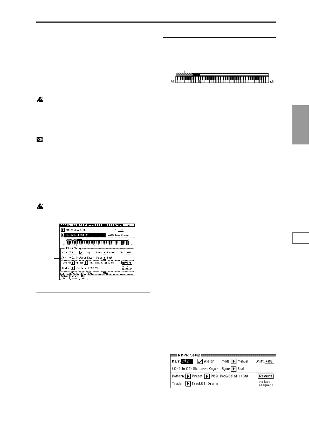
6–3: RPPR Setup
Here you can make settings for the RPPR (Realtime Pattern
Play/Recording) function. RPPR lets you assign patterns
from a song to individual keys, and then playback patterns
simply by pressing individual notes on the keyboard. The
results can be recorded to the sequencer.
For each song, you can assign either a preset pattern or a
user pattern to each of the seventy two keys in the range
C#2–C8. For each key, you can specify the pattern, track
number, and how the pattern will be played.
The arpeggiator is not operated by patterns played
back by RPPR. When RPPR is on, keys for which no
pattern is assigned will sound the track selected by
“T rack Select.” At this time, the arpeggiator will operate
if either arpeggiator A or B is selected for that track and
turned on. RPPR will not be triggered by notes generated by the arpeggiator.
When Local Control is OFF (“Local Control On” Global
P1: 1–1a), the keyboard will not trigger RPPR pattern
playback. Notes received at MIDI IN on the channel of
the track currently selected by “Track Select” will trigger patterns. If you have recorded only the trigger notes
on an external sequencer and wish to use the playback
from the external sequencer to trigger RPPR patterns on
TRITON STUDIO, set Local Control OFF.
If you want the note data generated by RPPR to be
recorded by the external sequencer, set Local Control
ON, and turn off the echo back function of the external
sequencer. (☞p.267)
In the RPPR Setup page, RPPR is turned on automatically. This will be the same result as when the RPPR
check box (0–1a) in each page is checked.
6–1
6–3a
6–3b
6–3c
6–3b: Keyboard & Assigned drawing
This shows the selected key, and the keys to which a pattern
has been assigned by the RPPR function. (Assignments are
not possible for the keys displayed in gray.)
Unassignable keys Assigned keys
Selected key
Unassigned keys
6–3c: RPPR Setup
KEY (Key Select) [C#2...C8]
Specifies the key to which you want to assign an RPPR pattern.
The following parameters will apply to the key that you
select here.
This can also be selected by holding down the [ENTER] key
and playing a note on the keyboard.
Assign [Off, On]
On (checked): When you playback the key specified by
“KEY,” the pattern selected in “Pattern” will be triggered.
Off (unchecked): That key will sound the currently selected
track at the corresponding pitch, just as in normal Sequencer
mode.
Pattern (Pattern Bank) [Preset, User]
Pattern Select [P000...149, U00...99]
Selects the RPPR pattern for the key selected in “KEY.” If the
selected user pattern contains no musical data, there will be
no sound when you press that key.
Track [Track 01...Track16: name]
Selects the track that will be used for the RPPR pattern
selected for the “KEY.” When you play the key, the pattern
will be played according to the settings of the track you
select here. Track settings are made in P0: Play/REC, P2: T rk
Param, P3: MIDI Filter, and P4: Zone/Ctrl. When you r ecord
in realtime with the RPPN function turned on, the data will
be recorded on the track you select here. (☞BG p.94)
The line below displays the program bank/name and MIDI
channel (Ch) that are specified for the “Track.”
Sequencer
P0
P1 P2 P3 P4 P5 P6 P7 P8 P9
6–3a: Song Select, Track Select, Tempo
Song Select [000...199: name]
Selects the desired song.
The RPPR settings will be assigned to the song you select
here.
Track Select [Track01...Track16, Master Track]
Selects the track that will be played by keys that are not
assigned to RPPR.
Select the track that you want to play from the keyboard.
(Tempo) [040...240, EXT]
Specifies the playback tempo of the patterns. (☞0–1a)
Revert
When you press this button, the “Pattern (Pattern Bank),”
“Pattern Select,” and “Track” settings of the last-edited
“KEY” for which “Assign” was checked will be copied to
these parameters of the currently selected “KEY”
Example: Assigning preset patterns P00, P01, and P02 to
“KEY”
Before you begin, assign a drum program such as INT-A036
to track 1.
1 Set “KEY” to C#2, and check “Assign.” Set “Pattern (Pat-
tern Bank)” to Preset, “Pattern Select” to P00, and
“Track” to Track01.
79
Page 91

2 Set “KEY” to D2, and press the Revert button.
The “Pattern (Pattern Bank),” “Pattern Select,” and
“Track” settings that you specified in step
1 will be cop-
ied automatically.
3 Edit only “Pattern Select.” Select “Pattern Select,” and
press the [ ] key to select P01: Pop&Balad 2/Std.
4 Set “KEY” to D#2, and press the Revert button.
The “Pattern (Pattern Bank)” P01: Pop&Balad 2/Std you
selected in step
3, as well as the “Pattern Select” and
“Track” settings, will be copied automatically.
5 As you did in step 3, set “Pattern Select” to P02:
Pop&Balad 3/Std.
By using “Revert” in this way, you can efficiently specify
“Pattern (Pattern Bank),” “Pattern Select,” and “Track” set-
tings for each “KEY” when creating RPPR data. This is particularly convenient when, as in the above example, the
patterns that you want to assign to the keys are numbered
consecutively (or are nearby each other), and use the same
track.
Mode [Once, Manual, Endless]
Specifies the way in which the pattern assigned to the speci-
fied “KEY” will be played.
Once: When you press the key, the complete pattern will
playback once to the end and then stop.
Manual: The pattern will continue repeating as long as you
continue holding the key, and will stop as soon as you
release the key.
Endless: The pattern will continue repeating even after you
release the key. To stop the pattern playback, press any note
below C2, or press the same key once again.
Key-on
START STOP
Once
START STOP
Manual
START STOP
Endless
Key-off
Same key, or C2
Key-off
Sync [Off, Beat, Measure, SEQ]
Specifies the way in which the pattern playback will be synchronized when you press the specified “KEY.”
Off: The pattern will begin playing at the moment you press
the note.
Beat: The pattern will synchronize to the beats of the pattern
that was started by the first key (i.e., the first note-on that
occurs from a condition where no notes of the keyboard are
pressed). This setting is suitable when you wish to play
phrase patterns in unison.
Measure: The pattern will synchronize to the measures of
the pattern that was started by the first key. This setting is
suitable for rhythm, bass or drum patterns.
SEQ: The pattern will synchronize to the measures of the
sequencer song.
Key 2 on
Sync settings
Key 1 off
Key 1 on
Song
Patterns 1 and 2 are set to
Mode=Manual, and have
identical Sync settings
Sync: OFF
Pattern 1
Pattern 2
Sync: Beat
Pattern 1
Pattern 2
Sync: Measure
Pattern 1
Pattern 2
Sync: SEQ
Pattern 1
Pattern 2
Shift [–12...+12]
Adjusts the playback pitch of the pattern for the specified
“KEY” in semitone steps over a range of ±1 octave.
With a setting of 0, the pattern will be played at its original
pitch.
80
• When Beat or Measure are selected, pattern playback
will begin when you press the first key. The second and
subsequent patterns that are triggered from the
keyboard will synchronize to the pattern that was
started by the first key; with a setting of Beat they will
synchronize in steps of a beat, and with a setting of
Measure they will synchronize in steps of a measure.
• When SEQ is selected, the pattern will playback in
synchronization with the measures of the sequencer
song. The pattern will synchronize with the currentlyplaying song, so you must start the song before you play
notes on the keyboard.
• Beat, Measure, and SEQ will cause the pattern to start
immediately if you play the key within a thirty-second
note of the timing of the respective beat or measure, but
if you play the key later than this, the start of the pattern
will be delayed by a beat.
Stopping playback of a RPPR pattern
By pressing C2 (or any note lower than C2), all the patterns
being played by RPPR will stop.
The patterns of keys whose “Sync” setting is Off will stop
immediately, but the playback of other keys will stop at the
beginning of the next beat or measure. Pattern playback of
keys whose “Sync” setting is other than Off can be stopped
immediately by rapidly pressing C2 or any lower note twice
in succession.
Page 92

Sequencer P7: Arpeggiator
Here you can specify how the arpeggiator will operate in
Sequencer mode. These settings can be made for each song.
In Sequencer mode (as in Combination mode), you can run
the two arpeggiators simultaneously. This allows you to
apply different arpeggio patterns to two sounds that have
been split across the keyboard, or use velocity to switch
between two different arpeggio patterns, etc.
In Sequencer mode, the musical data generated by the
arpeggiator during song track or pattern realtime-recording
can be recorded. While you record, you can modify the
arpeggio pattern and parameters, and adjust the [GATE]
knob and [VELOCITY] knob etc.
It is not possible to set the tempo of the arpeggiator and
the sequencer independently.
When “MIDI Clock” (Global P1: 1–1a) is Internal, the
arpeggiator can be synchronized to the internal sequencer.
(☞BG p.138)
• When you turn on the arpeggiator and press the
SEQUENCER [START/STOP] key, the arpeggiator will
synchronize to the timing of the sequencer.
• When you press the SEQUENCER [START/STOP] key,
the arpeggiator and sequencer will both stop. If you
wish to stop only the arpeggiator, press the
ARPEGGIATOR [ON/OFF] key to turn off.
When the arpeggiator “Key Sync” is off, you can turn on
the ARPEGGIATOR [ON/OFF] key and play the keyboard
to start the arpeggiator running during the pre-count before
realtime recording begins, so that the arpeggiator performance will be recorded from the beginning of the pattern at
the same time that recording begins.
When “MIDI Clock” is External MIDI or External
mLAN, the MIDI realtime clock messages transmitted
from the external MIDI device connected to MIDI IN or
the mLAN connector can perform the same type of control.
Even in this case, you can start/stop using the
SEQUENCER [START/STOP] key of the TRITON STUDIO’s sequencer.
7–1: Setup 1–8 (Setup T01–08) 7–2: Setup 9–16 (Setup T09–16)
7–1
0–1a
5–1b
0–1b
7–1a
7–1(2)a: Arpeggiator Assign, Arpeggiator Run A, B
Arpeggiator Assign [Off, A, B]
This assigns arpeggiator A or arpeggiator B to each track 1–
8, 9–16. When the ARPEGGIATOR [ON/OFF] key is turned
on, the arpeggiator specified for each track will run, subject
to the “Arpeggiator Run A, B” settings and setting here.
Off: The arpeggiator will not operate.
A: Arpeggiator A will operate. Use the Arpeggiator A page
to select the arpeggio pattern and set the parameters.
B: Arpeggiator B will operate. Use the Arpeggiator B page to
select the arpeggio pattern and set the parameters.
For tracks that you wish to realtime-record, select either
arpeggiator A or B. If you specify an arpeggiator for two or
more tracks, the arpeggiator will play each of the tracks you
specify.
You can set A and B to two different MIDI channels, and
control one from the keyboard and the other from an external MIDI device connected to MIDI IN. You can also use
multi-track recording (Multi REC) to simultaneously record
the note data that is generated from the two arpeggiators.
Example 1)
On tracks 1 and 2, set “MIDI Channel” (2–1a) to 01 and
“Status” (2–1a) to INT. Assign arpeggiator A to track 1
and arpeggiator B to track 2, and check “Arpeggiator
Run A, B” (7–1a). In “Track Select,” choose Track01.
With the ARPEGGIATOR [ON/OFF] key OFF, play the
keyboard and tracks 1 and 2 will sound simultaneously.
When you turn on the ARPEGGIATOR [ON/OFF] key
and play the keyboard, arpeggiator A will operate for
track 1 and arpeggiator B will operate for track 2.
Trigger
= Ch1
Trigger
= Ch1
Arpeggiator
A
Arpeggiator
B
Example 2)
For tracks 1, 2 and 3, set the “MIDI Channel” (2–1a) to
01, 02, and 03 respectively, and set “Status” (2–1a) to INT.
Assign arpeggiator A to tracks 1 and 2, and arpeggiator B
to track 3. Check the “Arpeggiator Run A, B” (7–1a) setting.
• In “Track Select,” choose Track01.
Playing the keyboard when the ARPEGGIATOR [ON/
OFF] key is off will play the sound assigned to track 1.
Playing the keyboard when the ARPEGGIATOR [ON/
OFF] key is on will cause arpeggiator A to operate for
tracks 1 and 2, and produce sound for both tracks.
• In “Track Select,” choose Track02.
Playing the keyboard when the ARPEGGIATOR [ON/
OFF] key is off will play the sound assigned to track 2.
Playing the keyboard when the ARPEGGIATOR [ON/
OFF] key is on will cause arpeggiator A to operate for
tracks 1 and 2, and produce sound for both tracks.
• In “Track Select,” choose Track03.
Playing the keyboard when the ARPEGGIATOR [ON/
OFF] key is off will play the sound assigned to track 3.
Playing the keyboard when the ARPEGGIATOR [ON/
OFF] key is on will cause arpeggiator B to operate for
track 3, and play the sound assigned to track 3.
Pattern - A
Pattern - B
Arpeggiator
Assign
Track1 MIDI Ch=1ch Status=INT
A
Track2 MIDI Ch=1ch Status=INT
B
Pattern - A
Pattern - B
Sequencer
P0
P1 P2 P3 P4 P5 P6 P7 P8 P9
81
Page 93

• Alternatively, you could choose Track01 in “Track
Select” to run arpeggiator A for tracks 1 and 2, and use
an external MIDI device connected to the TRITON
STUDIO’s MIDI IN to send note data to MIDI channel 3
to play arpeggiator B.
Arpeggiator
Assign
Trigger
= Ch1, Ch2
Trigger
= Ch3
Arpeggiator
Arpeggiator
Pattern - A
A
Pattern - B
B
A
Track1 MIDI Ch=1ch Status=INT
A
Track2 MIDI Ch=2ch Status=INT
Track3 MIDI Ch=3ch Status=INTB
Pattern - A
Pattern - A
Pattern - B
The arpeggiator cannot be triggered by the notes
played by the sequencer.
If the track “Status” (2–1a/2a) is set to INT or BTH,
tracks 1–16 to which arpeggiator A or B are assigned
will be sounded by the note data generated by the
arpeggiator, regardless of the “MIDI Channel” (2–1a/
2a) setting of that track. If the track “Status” is set to
BTH, EXT, or EX2, the track will transmit MIDI note
data on the “MIDI Channel” of that track.
In this case, arpeggiator A or B will be triggered by the
“MIDI Channel” of any track 1–16 to which the corresponding arpeggiator is assigned.
If the “Local Control On” (Global P1: 1–1a) is turned
OFF, the arpeggiator will not be triggered by note data
from the keyboard. It will be triggered by note data
received at MIDI IN. If you wish to record just the trigger notes on an external sequencer and run the TRITON
STUDIO’s arpeggiator in this way, turn Local Control
OFF.
If you want the note data generated by the arpeggiator
to be recorded on the external sequencer, turn Local
Control ON, and turn off the echo back function of the
external sequencer. (☞p.267)
Arpeggiator Run A, B
When the ARPEGGIATOR [ON/OFF] key is on, the arpeggiator(s) that are checked here will function for the track(s)
to which they are assigned by “Arpeggiator Assign.”
When the arpeggiator is on, A and B can be turned on/off
independently.
7–3: Arpegg. A (Arpeggiator A) 7–4: Arpegg. B (Arpeggiator B)
In the Arpegg. A page you can make settings for arpeggiator
A, and in the Arpegg. B page you can make settings for
arpeggiator B.
The “Copy Arpeggiator” (7–1A) page menu command
can also be used to copy arpeggiator settings from
another mode such as Program mode.
7–1
0–1a
5–1b
0–1b
7–3a
7–3(4)a: Arpeggiator–A(B) Setup
Pattern [P000...P004, U000(I-A/B)...U506(User)]
Octave [1, 2, 3, 4]
Resolution [ , , , , , ]
Gate [000...100(%), Step]
Velocity [001...127, Key, Step]
Swing [–100...+100(%)]
Sort [Off, On]
Latch [Off, On]
Key Sync. [Off, On]
Keyboard [Off, On]
These are the arpeggiator parameters for the song.
☞“Program 7–1: Arpegg. Setup (Arpeggiator Setup)”
▼ 7–1: Page Menu Command
0–1A
0–1B
0–1C
0–1D
0–1E
7–1A: Copy Arpeggiator
This command copies arpeggiator settings.
☞ “Combination 7–1A: Copy Arpeggiator.”
82
0–1F
7–1A
0–1I
0–1J
7–5: Scan Zone (Scan Zone A/B)
Specifies the range of notes and velocities that will trigger
each arpeggiator A and B.
7–1
0–1a
5–1b
0–1b
7–5a
7–5b
7–5a: Zone Map
This shows the Scan Zone settings for arpeggiators A and B.
(☞Combination “Zone Map” 7–4a)
Page 94

7–5b: Scan Zone A/B
A:
Top Key [C–1...G9]
Bottom Key [C–1...G9]
Specify the range of notes (keys) that will trigger arpeggiator A. “Top Key” is the upper limit, and “Bottom Key” is the
lower limit.
Top Velocity [001...127]
Bottom Velocity [001...127]
Specify the range of velocities that will trigger arpeggiator
A. “Top Velocity” is the upper limit, and “Bottom Velocity”
is the lower limit.
B:
Top Key [C–1...G9]
Bottom Key [C–1...G9]
Top Velocity [001...127]
Bottom Velocity [001...127]
Specify the range of notes (keys) and velocities that will trigger arpeggiator B (☞A:).
The value of these parameters can also be input by
holding down the [ENTER] key and playing a note on
the keyboard.
Sequencer P8: Insert Effect
Here you can make insert effect settings, and specify the bus
etc. for the program used by each track 1–16.
☞ For details on insert effects, refer to p.178 “8. Effect
Guide.”
8–1: Routing 1–8 (Routing T01–08) 8–2: Routing 9–16 (Routing T09–16)
Specify the bus to which the program oscillator(s) of each
track 1–16 will be sent. You can also set the amount of signal
that will be sent to the master effects.
8–1
8–1a
5–1b
0–1b
0–3a
8–1b
Sequencer
P0
P1 P2 P3 P4 P5 P6 P7 P8 P9
8–1a: Routing Map
This shows the status of the insert effects: the insert effect
routing, the names of the selected effects, the on/off status,
and chaining.
The effect type, on/off, and chain settings can be made in
the Insert FX page (8–2).
8–1(2)b: BUS Select (IFX/Indiv.Out BUS Select),
Send1 (MFX1), Send2 (MFX2)
BUS Select (IFX/Indiv.Out BUS Select)
[DKit, L/R, IFX1...5, 1...4, 1/2, 3/4, Off]
These settings specify the bus to which the program oscillator(s) of each track 1–16 will be sent.
The status of the settings can also be viewed in the “Routing
Map” (☞Combination P8–1: Routing).
When 1/2 or 3/4 are selected, the program of the corresponding track 1–16 will be output in stereo from
AUDIO OUTPUT (INDIVIDUAL) 1 and 2 or 3 and 4. If
you use CC#10 (pan) or AMS to control the panning of
the program oscillator, the new pan setting will be
applied at the next note-on. Unlike the case when you
select L/R to output the sound from (MAIN) L/MONO
and R, the pan of a sounding note cannot be varied in
realtime.
If you wish to vary the pan of a sounding note in realtime, and output the result from AUDIO OUTPUT
(INDIVIDUAL) 1 and 2 or 3 and 4, set “BUS Select” to
IFX1 (or IFX2–IFX5), select 000: No Effect for “IFX1”
(or IFX2–IFX5) (8–3), and select either 1/2 or 3/4 for
“BUS Select” (8–3) after the signal passes through IFX.
83
Page 95

Send1 (MFX1) [000...127]
Send2 (MFX2) [000...127]
Here you can adjust the send levels from tracks 1–16 to mas-
ter effects 1 and 2. This is valid when “BUS Select” is set
either to L/R or Off. If IFX 1, 2, 3, 4, or 5 is selected, the send
level to the master effects 1 and 2 is set by the “Send 1” and
“Send 2” parameters located in the Insert FX page, after the
signal passes through IFX 1–5.
These settings have no effect if “BUS Select” is set to 1, 2, 3,
4, 1/2 or 3/4.
The send 1 and 2 settings you make here will be used when
the song is played or recorded from the beginning. If you
change the settings while recording, the change will be
recorded as part of the musical data, and the send amount
will change when the data is played back. You can also
change these settings during playback. However if send 1
and 2 data has been recorded, the settings will change
accordingly.
If “Status” (2–1a/2a) is either INT or BTH, CC#93 and
#91 can be received to control send 1 and 2 respectively
and change their settings. When you switch songs or
return to the beginning of a song, tracks whose “Sta-
tus” is EXT, EX2 or BTH will transmit these settings via
MIDI. This data will be transmitted on the MIDI channel of each track as set by “MIDI Channel” (2–1a/2a).
The actual send level is determined by multiplying the
value of these parameters with the send level settings of
the oscillator(s) of the program used by the track
(“Send1” and “Send2,” Program P8: 8–1d).
▼ 8–1: Page Menu Command
0–1A
0–1B
8–1A
8–1B
8–1C
0–1I
0–1J
8–1A: Copy Insert Effect
☞ “Program P8: 8–1A: Copy Insert Effect.”
However, the MIDI contr ol channel specified in “Ctrl Ch” of
the IFX 1–5 page will not be copied.
8–1B: Swap Insert Effect
☞ “Program P8: 8–1B: Swap Insert Effect.”
However, the MIDI contr ol channel specified in “Ctrl Ch” of
the IFX 1–5 page will not be swapped.
8–1C: DrumKit IFX Patch
☞ “Combination P8: 8–1C: DrumKit IFX Patch.”
8–3: Insert FX
Here you can select the type of the insert effects, turn them
on/off, and make chain settings.
8–1
8–3a
8–3a: IFX1, 2, 3, 4, 5
IFX1, 5 [000...089]
IFX2, 3, 4 [000...102]
IFX1, 2, 3, 4, 5 On/Off [Off, ON]
Chain [Off, On]
Pan(CC#8) (Post IFX PanCC#8) [L000...C064...R127]
BUS Sel. (BUS Select) [L/R, 1, 2, 3, 4, 1/2, 3/4, Off]
Send1 [000...127]
Send2 [000...127]
These functions are the same as in Program mode. (☞Program 8–2a)
However unlike in Program mode, the “Ctrl Ch” (8–4a – 8a)
is used as the MIDI channel that controls insert effect
dynamic modulation (Dmod) and the “Pan (CC#8),” “Send
1,” and “Send 2” that follows the insert effect. The control
changes used are the same as in Program mode.
The pan (CC#8), send 1 and 2 settings you make here will be
used when the song is played or recorded from the beginning. If you change the settings while recording, the changes
will be recorded as part of the musical data, and the settings
will change when the data is played back. You can also
change these settings during playback. However if pan
(CC#8), send 1, or 2 data has been recorded, the settings will
change accordingly.
If “Status” (2–1a/2a) is either INT or BTH, CC#8,
CC#93, and CC#91 can be received to control the pan
following the insert effect, send 1, or send 2 respectively, and change their settings. When you switch
songs or return to the beginning of the song, tracks
whose “Status” is BTH, EXT, or EX2 will transmit these
settings via MIDI. This data will be transmitted on the
MIDI channels specified in the IFX 1–5 pages (8–4 – 8–
8).
84
Page 96

8–4: IFX 1 8–5: IFX 2 8–6: IFX 3 8–7: IFX 4
Sequencer P9: Master Effect
☞ For details on the master effects, refer to p.182 “8. Effect
Guide.”
8–8: IFX 5
Set the parameters for the effects selected for IFX 1–5 in the
Insert FX page (☞p.187–).
8–1
8–4a
8–4(~8)a: Ctrl Ch [Ch01...16, All Routed]
Selects the MIDI channel that will control effect
dynamic modulation (Dmod), pan following the insert
effect (CC#8), Send 1 (CC#93), and Send 2 (CC#91).
An asterisk “*” will appear at the right of the channel number Ch01–16 for tracks that are routed through these IFX. If
you have routed multiple tracks that have differing MIDI
channel settings, you can specify here which of these channels will be used to control the effect.
All Routed: Control can be performed from any of the MIDI
channels of the tracks that are routed.
If you have selected DKit as the “BUS Select” (8–1b/
2b) of a track for which a drum program is selected, the
MIDI channel of that timbre will be valid if All Routed
is selected for any one of IFX 1–5, regardless of the
“BUS Select” (Global P5: 5–2b) setting of the drum kit,
or of the setting of the “DrumKit IFX Patch” page
menu command.
9–1: Master FX
Here you can select the type of master effects, turn them on/
off, and make chain and master EQ settings. These parameters are the same as in Program mode. ☞“Program 9–1: Master FX (Master Effects)”
9–1
9–1a
Sequencer
9–1c
9–1b
P0
P1 P2 P3 P4 P5 P6 P7 P8 P9
▼ 9–1: Page Menu Command
0–1A
9–1A
9–1B
0–1I
0–1J
9–1A: Copy Master Effect
☞ “Program P9: 9–1A: Copy Master Effect.”
However, the MIDI contr ol channel specified in “Ctrl Ch” of
the MFX 1 and 2 pages will not be copied.
9–1B: Swap Master Effect
☞ “Program P9: 9–1B: Swap Master Effect.”
However, the MIDI contr ol channel specified in “Ctrl Ch” of
the MFX 1 and 2 pages will not be swapped.
85
Page 97
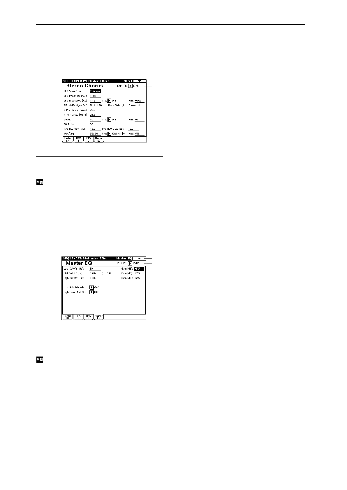
9–2: MFX 1 9–3: MFX 2
Here you can set the parameters of the MFX 1 and 2 effects
that were selected in the Master FX page (☞p.187–).
9–1
9–2a
9–2(3)a: Ctrl Ch
Ctrl Ch [Ch01...16, Gch]
Specifies the MIDI channel that will control dynamic
modulation (Dmod) for the master effects. If Gch is
selected, the global MIDI channel “MIDI Channel”
(Global P1: 1–1a) will be used.
9–4: Master EQ
The master EQ is a three-band stereo EQ. It is used to perform overall equalizing (tonal adjustment) on the sound
from the L/R bus immediately before it is output to AUDIO
OUTPUT (MAIN OUT) L/MONO and R (☞p.239).
0–1A
9–4a
9–4a: Ctrl Ch
Ctrl Ch [Ch01...16, Gch]
Specifies the MIDI channel that will control dynamic
modulation (Dmod) for the master EQ. If Gch is
selected, the global MIDI channel “MIDI Channel”
(Global P1: 1–1a) will be used.
The MEQ High Gain and MEQ Low gain can be controlled
by assigning a modulation source to the “Low Gain ModSrc:” and the “High Gain Mod-Src:” functions on this page.
86
Page 98

4. Sampling mode
An overview of sampling on the TRITON STUDIO
On the TRITON STUDIO, 48 kHz stereo 16-bit samples from
an external device connected to the AUDIO INPUT jacks, S/
P DIF IN jack, or mLAN connector (if the EXB-mLAN
option is installed) can be recorded into the internal sample
memory (RAM) or to the internal hard drive. At this time,
analog signals will be converted into digital signals, and
digital signals will be recorded while still in digital form.
A performance using the TRITON STUDIO’s filters, effects,
arpeggiator, and sequencer can be resampled.
The TRITON STUDIO comes with 16 Mbytes of sample
memory (RAM) and an internal hard disk. (☞For the capacity of the hard disk, refer to BG p.153)
The 16 Mbytes of sample memory (RAM) allow you to sample approximately 2 minutes 54 seconds in mono, or approximately 1 minute 27 seconds in stereo. By adding additional
72-pin SIMM boards, you can expand the memory to a maximum of 96 Mbytes (when the standard 16 Mbytes are
replaced by three 32 Mbyte SIMM boards). In this case, you
will be able to record up to six samples that are each approximately 2 minutes 54 seconds each for mono (or approximately 1 minute 27 seconds for stereo). (☞For details on the
72-pin SIMM boards that can be used, and how to install
them, refer to p.286)
When sampling to the hard drive, a single sample file can be
up to 80 minutes long for either stereo or mono (mono:
approximately 440 Mbyte, stereo: approximately 879
Mbyte). This will create a WAVE file.
The TRITON STUDIO supports a wide range of sources and
formats as described below.
Sampling mode
1. An analog audio signal from a mic or audio device connected to the AUDIO INPUT jacks can be converted into
a digital signal and sampled. An insert effect can also be
applied while sampling.
2. A digital audio signal from a digital audio device connected to the S/P DIF jack can be sampled directly. An
insert effect can also be applied while sampling. Sample
rates of 48 kHz and 96 kHz are supported for the S/P DIF
input and output. 96 kHz sample rate data will be converted into 48 kHz when it is sampled.
3. A digital audio signal from a digital audio device connected to the mLAN connector (if the EXB-mLAN option
is installed) can be sampled directly. An insert effect can
also be applied while sampling.
4. The analog audio output signal from an audio CD
inserted into the CDRW-1 option (if installed) is internally connected to the AUDIO INPUT jacks. The CD can
be played back on the TRITON STUDIO, and the analog
audio signal converted into a digital signal and sampled.
(If you are using a CD-R/RW drive connected to the SCSI
connector, use a cable to connect it to the AUDIO INPUT
jacks.)
5. A digital audio signal from an audio CD played back on
the CDRW-1 option (if installed) or a CD-R/RW drive
connected to the SCSI connector can be sampled directly
(the Ripping function).
6. Resampling can be performed by applying insert effects
to one or more existing samples, and once again sampling them internally. You can select either “Auto,” wher e
insert effect processing will be performed automatically
on the sample you specify, or “Manual,” where you can
manually apply an insert effect and play the sample manually for resampling.
Program, Combination, and Sequencer modes
1. A performance that uses the various functions of each
mode (filters, effects, arpeggiator, sequencer, etc.) can be
resampled. (☞Program: p.4, Combination: p.36,
Sequencer: p.49, 56)
2. External audio sources can be sampled from the various
input jacks (see “Sampling mode” paragraphs 1, 2, and 3,
above). At this time, you can mix your playing on the
TRITON STUDIO with the external audio, or monitor
your playing on the TRITON STUDIO while sampling
only the external audio from the input jacks. You can also
add the master effects when sampling.
3. In Sequencer mode, you can sample an external audio
source while the sequencer song plays back, and the
appropriate note data will automatically be created in a
track. This lets you sample vocals or guitar while the
sequencer is running, just as though you were using a
multi-track recorder. (In-Track Sampling function)
Samples recorded in Sampling mode, or in the Program,
Combination, and Sequencer modes can be used as waveforms for the tone generator.
Samples recorded to sample memory (RAM) can be used as
tone generator waveforms.
Samples recorded to the hard disk (WAVE files) can be
loaded into sample memory (RAM) and used as tone generator waveforms. WAVE files can also be written to the
CDRW-1 option (if installed) or a CD-R/RW drive connected to the SCSI connector, to create an audio CD.
Individual samples (WAVE files) from the hard disk up
to 16 Mbyte in size for mono or 32 Mbyte for stereo (if
the sample memory has been expanded to 32 Mbyte or
more) can be loaded into sample memory (RAM).
Editing in Sampling mode
In Sampling mode, sample data created via sampling or
loaded from media (including WAVE or AIFF formats) can
be assigned to indexes (zones) to create a multisample. One
multisample can contain multiple indexes.
A multisample you create can easily be converted into a pr ogram (☞“Convert MS to Program” 0–1G). When a multisample is converted, the filter, amp, and effect settings will
automatically be created with the program. The program
can also be used in Combination mode or Sequencer mode.
A sample can also be used as a drum sample in a drum kit.
Index 001
0000:
Sample A
Multisample
Sample
Index001
Top Key
Index 002
0001:
Sample B
Drum Kit
Multisample
Index002
Top Key
Index003
Top Key
Index 003
0002:
Sample C
Program OSC (Single/Double)
Program OSC (Drums)
Index 004
0003:
Sample D
Index004
Top Key
Sampling
P0
P1 P2 P3 P4 P5 P8
87
Page 99

Regardless of the page you are in, the selected multisample or sample will sound when you play the keyboard, allowing you to hear the edited content of that
page.
When you turn off the power, all multisample and sample data in Sampling mode will be lost. Before you turn
off the power, be sure to save important data to floppy
disk, hard disk, CD-R/RW or external SCSI device
(☞BG p.60).
When the TRITON STUDIO is turned on, memory will
contain no multisamples or samples, so you will first
need to load previously-saved data before you can
playback or edit it.
There is no Compare function that allows you to restore
sample data to the state it was in before it was edited. If
you wish to preserve the unedited state of the data, use
“Copy MS” (0–1E) or “Copy Sample” (0–1B) etc. to
make a copy of the multisample or sample before you
begin editing.
In some of the page menu commands in P1 or P2, you
can uncheck the “Overwrite” item in the dialog box so
that the unedited sample data will be preserved even
after you execute the command (☞1–1: Page Menu
Command “About Overwrite”).
When executing a sample edit operation or when you
finish recording a stereo sample, you may hear a slight
noise. This does not affect the audio data that has been
edited or sampled.
Cautions regarding sample data
• The sample data memory areas Bank 1–6 each contain
16 Mbyte. Of this 16 Mbyte (8,388,608 samples), sixteen
samples (the first and last eight samples) are used as
internal work area.
• The first and last samples of each sample are used as
internal work area. These two samples are added
automatically when a sample is recorded or when an
.AIFF or .WAVE file is loaded. This means that if you
record a sample of one second, this will result in 48,000
samples of data, but four samples will be added to this,
so that sample memory (RAM) will actually contain
48,004 samples of data.
If “Auto Optimize RAM” (Global P0: 0–3b) is on, and
the writing destination for sampling data is RAM, the
sample memory (RAM) will automatically be optimized after the data has been written. This is turned on
by default, but you may switch it on/off as necessary.
(☞“Optimize RAM” 0–1M)
Sampling P0: Recording
Here you can set the input level and make other basic settings for sampling (sample recording), and make basic settings for multisamples and samples.
Normally you will record samples in this page.
0–1: Recording
Here you can select the multisample that you wish to record,
specify the index sample, make settings, select the memory
bank, and adjust the final level of the input signal.
0–1
0–1a
0–1b
0–1c
0–1d
0–1a: MS, Index, Keyboard & Index
MS (Multisample Select) [000...999]
Selects the multisample.
Each multisample consists of the samples for one or more
indexes (an “index” is a range or zone of keys).
This parameter can also be set from P1–P3.
To create a new multisample,
1 Press the “MS” popup button to access the popup menu,
and select a number for which the multisample name is
blank.
Alternatively, use the numeric keys [0]–[9] to specify a
new multisample number, and press the [ENTER] key.
When you select a new multisample number, the “Create
New Multisample” dialog box will appear.
2 If you wish to create a stereo multisample, check “Ste-
reo.”
3 To create the multisample, press the OK button. To can-
cel, press the Cancel button.
A multisample will be created as follows (example).
Mono type 001: NewMS_ _ _ _ _ _001
Stereo type 001: NewMS_ _ _ _ _ _001-L
001: NewMS_ _ _ _ _ _001-R
88
Index [xxx (001...128)/yyy (001...128)]
Selects the index for which you wish to sample.
Each zone in a multisample is called an “index.” For example on the 61 note keyboard, a multisample could be divided
into six zones of one octave (12 keys) each. Each of these
zones is referred to as an “index.” You will assign a sample
to each of these indexes.
xxx: The selected index. Choose the desired index.
yyy: The total number of indexes in the multisample.
Page 100

You can also select an index by holding down the
[ENTER] key and playing a note on the keyboard. The
index that includes this note will be selected. The key
you specify will be the base key, and will be displayed
in gray in “Keyboard & Index” (☞“Keyboard &
Index”).
This parameter can also be set from P1: Sample Edit, P2:
Loop Edit, or P3: Multisample. Sampling and editing in the
respective page will apply to the index that you select here.
When the power is turned on, this index will default to 001/
001. This indicates that only one index exists. T o incr ease the
number of indexes, use “Create” in this page. When you
press the Create button, indexes will automatically be
added from the left-most zone, as 002/002, 003/003, ... (The
position, zone width, and original key location of the index
that is created when you press the Create button can be set
in Create Zone Preference (0–3a, 3–2a). You are also free to
modify the zone width and original key location later.)
Keyboard & Index
Original Key (currently selected Original Key is reversed)
Index zone (currently selected Index is reversed)
Index01 Index02 Index03 Index04 Index05
C4 key
Lowest note of the
displayed keyboard
By holding down the [ENTER] key and playing a note, you can select the corresponding
index, and the specified key will be the base key and will be shown in gray.
Keyboard range
This displays the zones and original keys of the selected
multisample. The black triangle shows the keyboard range,
and the white triangle shows the C4 key. The note numbers
at left and right show the keyboard note range that is displayed.
The base key (displayed in gray)
• In P1: Sample Edit you can press the SAMPLING
[START/STOP] key to play the sample of the selected
“Index” in one-shot mode from “Edit Range Start”–“Edit
Range End.” At this time, the sample will sound at the
pitch of the base key.
• Playback in the grid display of P1 and P2 will be
according to the playback pitch of the base key selected
here, and the specified tempo BPM/resolution (set in P1
and P2).
• The “Pitch BPM Adjust” (3–1A) function is based on the
playback pitch of the base key you specify here.
You can use the “Keyboard Display” (0–1J) page menu command to change the displayed range of the keyboard.
Highest note of the
displayed keyboard
----: ---No Assign----: No sample is assigned to the index.
There will be no sound when you play the keyboard.
To record a sample, select a vacant sample such as 0000:.
When you record a sample, data will be loaded into the
selected sample. The sample name (such as
NewSample_0000) will be shown beside the number. This
sample name can be modified using the “Rename Sample”
(0–1C) page menu command.
You can also record a sample even when ----:---No Assign---
- is displayed. In this case, a sample number will be selected
automatically.
Even if you record to a sample that already contains data,
the selected sample will not be overwritten –the data will
automatically be sampled to a vacant sample, and the newly
recorded sample will replace the previous sample in the
index. If you wish to delete a sample, execute the “Delete
Sample” (0–1A) page menu command.
When you press the popup button, the thousand samples that include the selected sample will be displayed.
To select the thousand’s place, use the VALUE controllers.
OrigKey (Original Key) [C–1...G9]
Specifies the key that will play the sample at its original
pitch (i.e., the pitch at which it was recorded). The pitch will
change in semitone steps relative to the original key.
For example, suppose that you recorded a sample with
“OrigKey” of F2. When the zone of the index is C2–B2,
pressing the F2 key would playback the sample at its original pitch. Pressing F#2 would playback the sample a semitone higher. Pressing E2 would playback the sample a
semitone lower. The pitch of this sampled sound will change
in semitone steps between C2 and B2, centered at F2.
The original key location can also be viewed in “Keyboard &
Index.”
If “Constant Pitch” (3–1b) is checked, the sample will
be sounded at its original pitch by all notes in the zone.
TopKey (Top Key) [C–1...G9]
Specifies the highest key in the zone of the index. The zone
is defined by this “Top Key.”
For example, suppose that you set a “TopKey” of B2 for
index 001/002, and a “TopKey” of B3 for index 002/002.
This means that the zone of index 001 will be B2 and lower,
and the zone of index 002 will be C3–B3.
Range
This indicates the zone (area) that was determined by the
“TopKey” setting.
The sample selected by “Sample Select” will sound in this
area. The zone for each index can also be viewed in “Keyboard & Index.”
Sampling
P0
P1 P2 P3 P4 P5 P8
0–1b: Sample Select, OrigKey, TopKey, Create
Here you can set the sample, original key, and range of the
selected index.
Sample Select [----: ---No Assign----, 0000...3999]
Selects a sample that you sampled or loaded in Disk mode,
and play a note within the index range to sound that sample.
This parameter can also be set from P1–P3 (Multisample
pages). Sampling and editing in the respective page will
apply to the sample you select here.
Create
This creates an index. Use this when you wish to add a sample to a multisample.
When you press the Create button, a new index will be created according to the Create Zone Preference (0–3a, 3–2a)
parameters “Position,” “Zone Range,” and “Original Key
Position.” If you wish to delete an index or exchange
indexes, use P3: Multisample.
If when you execute “Create” (0–1b, 3–1c) or “Insert”
(3–1c) it is not possible to create a new index according
to your Create Zone Preference settings, one of the following dialog boxes will appear. If you wish to create a
new index, perform the following procedure.
• Set Top Key: Select “Index” 001, set “Position” (0–3a,
3–2a) to Left (to Selected Index), and execute “Create”
89
 Loading...