

Page 1

3E
Page 2
5.3–1a
5.3–1b
5.3–1c
5.3–1d
BG
PG
1 2 3
☞ p. ■ , ☞
■ , ☞■ . ■
■
Boldface type
About this manual
Parameter values are printed in boldface type.
Content that is of particular importance is also printed in
This “Parameter Guide” contains explanations and other
information regarding the operations of the parameters and
settings on the TRITON-Rack. The explanations are organized by mode, page, and tab. Explanations and other information on the effects and their parameters are also provided
for each effect.
Refer to this guide when an unfamiliar parameter appears in
the display, or when you need to know more about a particular function.
boldface type.
Procedure steps
Steps in a procedure are listed as
BG p.
1
2
3
...
...
–
From the left, these symbols indicate a reference page in the
Parameter Guide, a reference page in the Basic Guide, and a
parameter number.
Symbols , , , , ,
These symbols respectively indicate cautions, advice, MIDIrelated explanations, a parameter that can be selected as an
Conventions in this manual
Abbreviations for the manuals BG, PG, VNL
References to the manuals included with the TRITON-Rack
are abbreviated as follows.
: Basic Guide
: Parameter Guide
VNL : Voice Name List
Switches and knobs [ ]
References to the keys, dials, and knobs on the TRITONRack’s panel are enclosed in square brackets [ ]. References
to
buttons or tabs indicate objects in the LCD display
alternate modulation source, a parameter that can be
selected as a dynamic modulation source, and a parameter
that can use the BPM/MIDI Sync function.
Example screen displays
The values of the parameters shown in the example screens
of this manual are only for explanatory purposes, and may
not necessary match the values that appear in the LCD
screen of your instrument.
MIDI-related explanations
CC# is an abbreviation for Control Change Number.
In explanations of MIDI messages,
brackets [ ]
always indicate hexadecimal numbers.
numbers in square
screen.
Parameters in the LCD display screen “ ”
Parameters displayed in the LCD screen are enclosed in
double quotation marks “ ”.
How to read the “Parameter Guide”
(example)
Mode name
Page No.
Tab No.
Tab name
Parameter
No.
Parameter
name
Here you can make settings for the LFO that can be used to
cyclically modulate the Pitch, Filter, and Amp of oscillators 1
and 2. There are two LFO units for each oscillator. By setting
the LFO1 or LFO2 Intensity to a negative (–) value for Pitch,
Filter, or Amp, you can invert the LFO waveform.
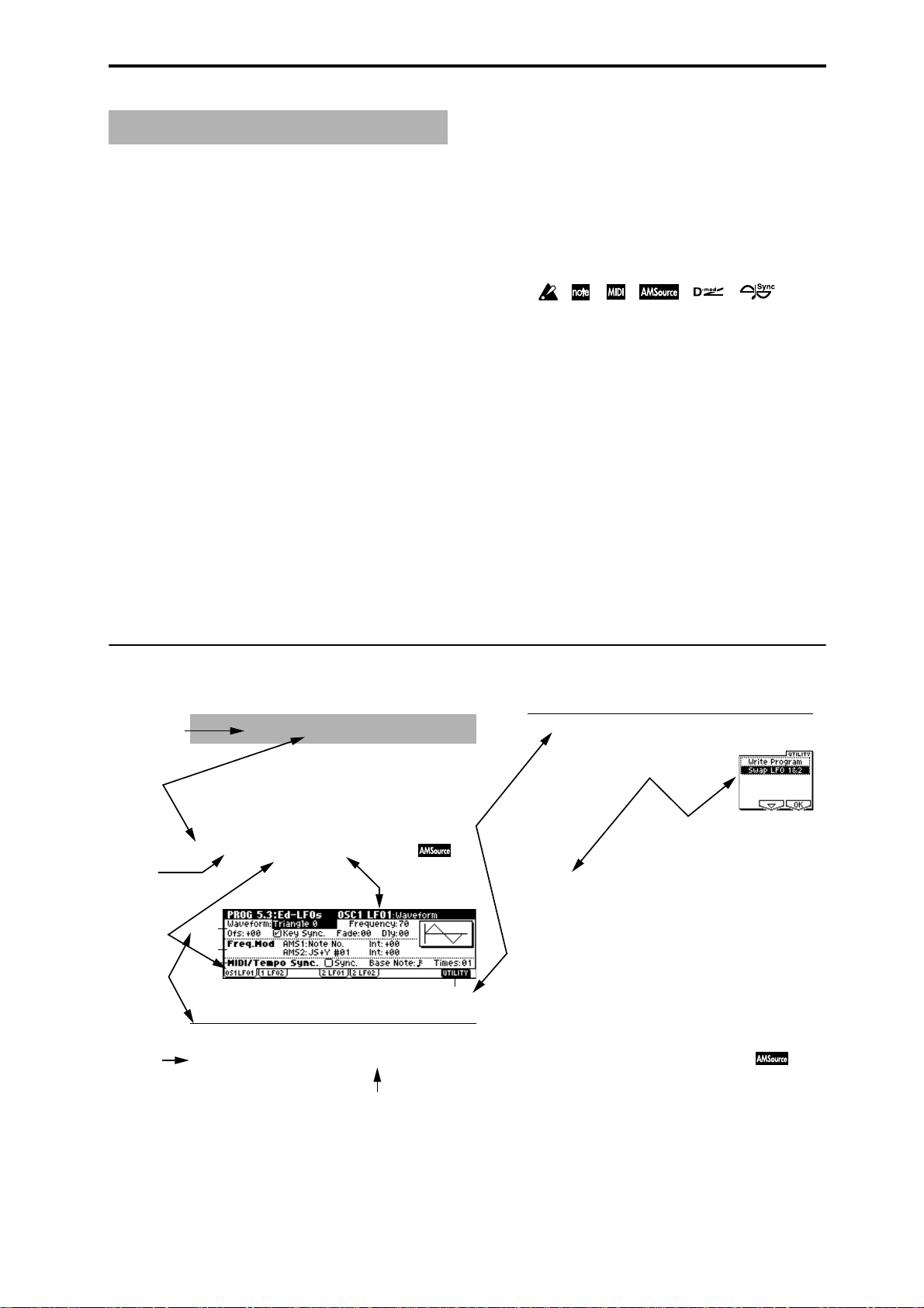
5.3–1: OS1LFO1 (OSC1 LFO1)
Indicates settings for the “OSC1 LFO1,” which is the first
LFO that can be used for oscillator 1.
5.3–1a: OSC1 LFO1
Waveform [Triangle 0…Random6 (Vect.)]
PROG 5.3: Ed–LFOs
Page name
Range of possible
parameter values
Utility menu
command No.
■ 5.3–1d: UTILITY
Utilty menu
command name
☞“Write Program” (1.1–1d)
For details on how to select the desired utility function,
refer to “PROG 1.1–1d: UTILITY.”
Swap LFO 1&2
This exchanges the settings of LFO 1 and 2. If LFO2 is
selected in AMS1 (Freq. AMS1) or AMS2 (Freq. AMS2) of
LFO1 Freq.Mod (5.3–1b), the settings will be invalid for
LFO2 after LFO1 and 2 have been exchanged. If you select
this from the OSC1 LFO1 or OSC1 LFO2 page, LFO1 and
LFO2 of OSC1 will be exchanged.
1 Select “Swap LFO 1&2” to access the dialog box.
2 To execute, press the [F8] (“OK”) key. To cancel without
executing, press the [F7] (“Cancel”) key.
5.3–2: OS1LFO2 (OSC1 LFO2)
iii
Page 3

Table of Contents
About this manual . . . . . . . . . . . . . . . . . . . . . . . . . . . . . . iii
Conventions in this manual. . . . . . . . . . . . . . . . . . . . . . . . . . . . .iii
How to read the “Parameter Guide” . . . . . . . . . . . . . . . . . . . . . .iii
1. Program mode . . . . . . . . . . . . . . . . . . . . . . . 1
PROG PAGE MENU . . . . . . . . . . . . . . . . . . . . . . . . . . . . . .1
PROG 1.1: Play. . . . . . . . . . . . . . . . . . . . . . . . . . . . . . . . . .2
1.1–1: Program. . . . . . . . . . . . . . . . . . . . . . . . . . . . . . . . . . . . . .2
1.1–2: P.Edit (Performance Editor). . . . . . . . . . . . . . . . . . . . . . .3
1.1–3: Arp (Arp. Play). . . . . . . . . . . . . . . . . . . . . . . . . . . . . . . . .5
PROG 2.1: Ed–Basic . . . . . . . . . . . . . . . . . . . . . . . . . . . . .5
2.1–1: Basic (Prog Basic). . . . . . . . . . . . . . . . . . . . . . . . . . . . . .5
2.1–2: OSC1. . . . . . . . . . . . . . . . . . . . . . . . . . . . . . . . . . . . . . . .7
2.1–3: OSC2. . . . . . . . . . . . . . . . . . . . . . . . . . . . . . . . . . . . . . . .9
2.1–4: V.Zone (Velocity Zone) . . . . . . . . . . . . . . . . . . . . . . . . . .9
2.1–5: Audit. (Audition). . . . . . . . . . . . . . . . . . . . . . . . . . . . . . . .9
PROG 2.2: Ed–Ctrl . . . . . . . . . . . . . . . . . . . . . . . . . . . . . . .9
2.2–1: Ctrls (Controls). . . . . . . . . . . . . . . . . . . . . . . . . . . . . . . . .9
PROG 2.3: Ed–OSC . . . . . . . . . . . . . . . . . . . . . . . . . . . . .10
5.3–2: OS1LFO2 (OSC1 LFO2) . . . . . . . . . . . . . . . . . . . . . . . 24
5.3–3: OS2LFO1 (OSC2 LFO1) . . . . . . . . . . . . . . . . . . . . . . . 24
5.3–4: OS2LFO2 (OSC2 LFO2) . . . . . . . . . . . . . . . . . . . . . . . 24
PROG 6.1: Ed–Arp. (Arpeggiator) . . . . . . . . . . . . . . . . . 24
6.1–1: Setup (Arpeg. Setup) . . . . . . . . . . . . . . . . . . . . . . . . . . 24
6.1–2: Zone (Scan Zone) . . . . . . . . . . . . . . . . . . . . . . . . . . . . 26
PROG 7.1: Ed–BUS. . . . . . . . . . . . . . . . . . . . . . . . . . . . . 26
7.1–1: BUS . . . . . . . . . . . . . . . . . . . . . . . . . . . . . . . . . . . . . . . 26
7.1–2: Route (Routing) . . . . . . . . . . . . . . . . . . . . . . . . . . . . . . 27
PROG 7.2: Ed–InsertFX . . . . . . . . . . . . . . . . . . . . . . . . . 28
7.2–1: Setup . . . . . . . . . . . . . . . . . . . . . . . . . . . . . . . . . . . . . . 28
7.2–2: IFX 1. . . . . . . . . . . . . . . . . . . . . . . . . . . . . . . . . . . . . . . 28
7.2–3: IFX 2. . . . . . . . . . . . . . . . . . . . . . . . . . . . . . . . . . . . . . . 28
7.2–4: IFX 3. . . . . . . . . . . . . . . . . . . . . . . . . . . . . . . . . . . . . . . 28
7.2–5: IFX 4. . . . . . . . . . . . . . . . . . . . . . . . . . . . . . . . . . . . . . . 28
7.2–6: IFX 5. . . . . . . . . . . . . . . . . . . . . . . . . . . . . . . . . . . . . . . 28
7.2–7: Routing. . . . . . . . . . . . . . . . . . . . . . . . . . . . . . . . . . . . . 29
PROG 7.3: Ed–MasterFX . . . . . . . . . . . . . . . . . . . . . . . . 29
7.3–1: Setup . . . . . . . . . . . . . . . . . . . . . . . . . . . . . . . . . . . . . . 29
7.3–2: MFX 1. . . . . . . . . . . . . . . . . . . . . . . . . . . . . . . . . . . . . . 30
7.3–3: MFX 2. . . . . . . . . . . . . . . . . . . . . . . . . . . . . . . . . . . . . . 30
7.3–4: MEQ (Master EQ). . . . . . . . . . . . . . . . . . . . . . . . . . . . . 30
PROG 3.1: Ed–Pitch. . . . . . . . . . . . . . . . . . . . . . . . . . . . .10
3.1–1: OSC1. . . . . . . . . . . . . . . . . . . . . . . . . . . . . . . . . . . . . . .10
3.1–2: OS1lfo (OSC1 LFO). . . . . . . . . . . . . . . . . . . . . . . . . . . .11
3.1–3: OSC2. . . . . . . . . . . . . . . . . . . . . . . . . . . . . . . . . . . . . . .12
3.1–4: OS2lfo (OSC2 LFO). . . . . . . . . . . . . . . . . . . . . . . . . . . .12
3.1–5: EG (Pitch EG) . . . . . . . . . . . . . . . . . . . . . . . . . . . . . . . .12
PROG 4.1: Ed–Filter1. . . . . . . . . . . . . . . . . . . . . . . . . . . .14
4.1–1: Basic . . . . . . . . . . . . . . . . . . . . . . . . . . . . . . . . . . . . . . .14
4.1–2: Mod.1 (Filter1 Modulation1). . . . . . . . . . . . . . . . . . . . . .15
4.1–3: Mod.2 (Filter1 Modulation2). . . . . . . . . . . . . . . . . . . . . .16
4.1–4: lfoMod (LFO Modulation). . . . . . . . . . . . . . . . . . . . . . . .16
4.1–5: EG (Filter1 EG) . . . . . . . . . . . . . . . . . . . . . . . . . . . . . . .17
PROG 4.2: Ed–Filter2. . . . . . . . . . . . . . . . . . . . . . . . . . . .19
4.2–1: Basic . . . . . . . . . . . . . . . . . . . . . . . . . . . . . . . . . . . . . . .19
4.2–2: Mod.1 (Filter2 Modulation1). . . . . . . . . . . . . . . . . . . . . .19
4.2–3: Mod.2 (Filter2 Modulation2). . . . . . . . . . . . . . . . . . . . . .19
4.2–4: lfoMod (LFO Modulation). . . . . . . . . . . . . . . . . . . . . . . .19
4.2–5: EG (Filter2 EG) . . . . . . . . . . . . . . . . . . . . . . . . . . . . . . .19
PROG 5.1: Ed–Amp1 . . . . . . . . . . . . . . . . . . . . . . . . . . . .19
5.1–1: Lvl/Pan (Level/Pan). . . . . . . . . . . . . . . . . . . . . . . . . . . .19
5.1–2: Mod. (Amp1 Modulation). . . . . . . . . . . . . . . . . . . . . . . .20
5.1–3: EG (Amp1 EG) . . . . . . . . . . . . . . . . . . . . . . . . . . . . . . .21
PROG 5.1: Ed–Amp . . . . . . . . . . . . . . . . . . . . . . . . . . . . .22
PROG 5.2: Ed–Amp2 . . . . . . . . . . . . . . . . . . . . . . . . . . . .22
5.2–1: Lvl/Pan (Level/Pan). . . . . . . . . . . . . . . . . . . . . . . . . . . .22
5.2–2: Mod. (Amp2 Modulation). . . . . . . . . . . . . . . . . . . . . . . .22
5.2–3: EG (Amp2 EG) . . . . . . . . . . . . . . . . . . . . . . . . . . . . . . .22
PROG 5.2: Ed–EGs. . . . . . . . . . . . . . . . . . . . . . . . . . . . . .22
PROG 5.3: Ed–LFOs. . . . . . . . . . . . . . . . . . . . . . . . . . . . .23
5.3–1: OS1LFO1 (OSC1 LFO1) . . . . . . . . . . . . . . . . . . . . . . .23
2. Combination mode . . . . . . . . . . . . . . . . . . . 31
COMBI PAGE MENU. . . . . . . . . . . . . . . . . . . . . . . . . . . . 31
COMBI 1.1: Play. . . . . . . . . . . . . . . . . . . . . . . . . . . . . . . . 31
1.1–1: Combi (Combination). . . . . . . . . . . . . . . . . . . . . . . . . . 31
1.1–2: Prog (Timbre Program) . . . . . . . . . . . . . . . . . . . . . . . . 32
1.1–3: Mix (Mixer) . . . . . . . . . . . . . . . . . . . . . . . . . . . . . . . . . . 34
1.1–4: Arp. A (Arpeggio Play A) . . . . . . . . . . . . . . . . . . . . . . . 34
1.1–5: Arp. B (Arpeggio Play B) . . . . . . . . . . . . . . . . . . . . . . . 34
COMBI 2.1: Ed–Prog/Mixer. . . . . . . . . . . . . . . . . . . . . . . 35
2.1–1: Prog (Timbre Program) . . . . . . . . . . . . . . . . . . . . . . . . 35
2.1–2: Mix (Mixer) . . . . . . . . . . . . . . . . . . . . . . . . . . . . . . . . . . 35
COMBI 2.2: Ed–Ctrl. . . . . . . . . . . . . . . . . . . . . . . . . . . . . 36
2.2–1: Ctrls (Controls). . . . . . . . . . . . . . . . . . . . . . . . . . . . . . . 36
COMBI 2.3: Ed–MOSS. . . . . . . . . . . . . . . . . . . . . . . . . . . 36
COMBI 3.1: Ed–Param1 . . . . . . . . . . . . . . . . . . . . . . . . . 36
3.1–1: MIDI . . . . . . . . . . . . . . . . . . . . . . . . . . . . . . . . . . . . . . . 36
3.1–2: OSC . . . . . . . . . . . . . . . . . . . . . . . . . . . . . . . . . . . . . . . 37
3.1–3: Pitch. . . . . . . . . . . . . . . . . . . . . . . . . . . . . . . . . . . . . . . 37
COMBI 3.2: Ed–Param2 . . . . . . . . . . . . . . . . . . . . . . . . . 38
3.2–1: Other . . . . . . . . . . . . . . . . . . . . . . . . . . . . . . . . . . . . . . 38
COMBI 3.3: Ed–Key Zone. . . . . . . . . . . . . . . . . . . . . . . . 39
3.3–1: Key (Key Zone) . . . . . . . . . . . . . . . . . . . . . . . . . . . . . . 39
3.3–2: Slope (Key Slope) . . . . . . . . . . . . . . . . . . . . . . . . . . . . 39
3.3–3: Review . . . . . . . . . . . . . . . . . . . . . . . . . . . . . . . . . . . . . 39
COMBI 3.4: Ed–Vel Zone (Velocity Zone) . . . . . . . . . . . 40
3.4–1: Vel (Velocity Zone). . . . . . . . . . . . . . . . . . . . . . . . . . . . 40
3.4–2: Slope (Velocity Slope) . . . . . . . . . . . . . . . . . . . . . . . . . 40
3.4–3: Review . . . . . . . . . . . . . . . . . . . . . . . . . . . . . . . . . . . . . 40
iv
Page 4

COMBI 4.1: Ed–MIDI Filter1. . . . . . . . . . . . . . . . . . . . . . .41
4.1–1: MIDI 1–1 (MIDI Filter 1–1). . . . . . . . . . . . . . . . . . . . . . .41
4.1–2: MIDI 1–2 (MIDI Filter 1–2). . . . . . . . . . . . . . . . . . . . . . .41
COMBI 4.2: Ed–MIDI Filter2. . . . . . . . . . . . . . . . . . . . . . .41
4.2–1: MIDI 2–1 (MIDI Filter 2–1). . . . . . . . . . . . . . . . . . . . . . .41
4.2–2: MIDI 2–2 (MIDI Filter 2–2). . . . . . . . . . . . . . . . . . . . . . .42
COMBI 4.3: Ed–MIDI Filter3. . . . . . . . . . . . . . . . . . . . . . .42
4.3–1: MIDI 3–1 (MIDI Filter 3–1). . . . . . . . . . . . . . . . . . . . . . .42
4.3–2: MIDI 3–2 (MIDI Filter 3–2). . . . . . . . . . . . . . . . . . . . . . .42
COMBI 4.4: Ed–MIDI Filter4. . . . . . . . . . . . . . . . . . . . . . .42
4.4–1: MIDI 4–1 (MIDI Filter 4–1). . . . . . . . . . . . . . . . . . . . . . .42
4.4–2: MIDI 4–2 (MIDI Filter 4–2). . . . . . . . . . . . . . . . . . . . . . .43
COMBI 6.1: Ed–Arp. (Arpeggiator). . . . . . . . . . . . . . . . .43
6.1–1: Setup. . . . . . . . . . . . . . . . . . . . . . . . . . . . . . . . . . . . . . .43
6.1–2: Arp. A (Arpeggiator A). . . . . . . . . . . . . . . . . . . . . . . . . .44
6.1–3: Arp. B (Arpeggiator B). . . . . . . . . . . . . . . . . . . . . . . . . .44
6.1–4: Zone (Scan Zone) . . . . . . . . . . . . . . . . . . . . . . . . . . . . .45
COMBI 7.1: Ed–BUS. . . . . . . . . . . . . . . . . . . . . . . . . . . . .45
7.1–1: BUS. . . . . . . . . . . . . . . . . . . . . . . . . . . . . . . . . . . . . . . .45
7.1–2: Route (Routing). . . . . . . . . . . . . . . . . . . . . . . . . . . . . . .46
COMBI 7.2: InsertFX. . . . . . . . . . . . . . . . . . . . . . . . . . . . .47
7.2–1: Setup. . . . . . . . . . . . . . . . . . . . . . . . . . . . . . . . . . . . . . .47
7.2–2: IFX 1 . . . . . . . . . . . . . . . . . . . . . . . . . . . . . . . . . . . . . . .47
7.2–3: IFX 2 . . . . . . . . . . . . . . . . . . . . . . . . . . . . . . . . . . . . . . .47
7.2–4: IFX 3 . . . . . . . . . . . . . . . . . . . . . . . . . . . . . . . . . . . . . . .47
7.2–5: IFX 4 . . . . . . . . . . . . . . . . . . . . . . . . . . . . . . . . . . . . . . .47
7.2–6: IFX 5 . . . . . . . . . . . . . . . . . . . . . . . . . . . . . . . . . . . . . . .47
7.2–7: Route (Routing). . . . . . . . . . . . . . . . . . . . . . . . . . . . . . .47
COMBI 7.3: Ed–MasterFX . . . . . . . . . . . . . . . . . . . . . . . .48
7.3–1: Setup. . . . . . . . . . . . . . . . . . . . . . . . . . . . . . . . . . . . . . .48
7.3–2: MFX1 (Master Effect1). . . . . . . . . . . . . . . . . . . . . . . . . .48
7.3–3: MFX2 (Master Effect2). . . . . . . . . . . . . . . . . . . . . . . . . .48
7.3–4: MEQ (Master EQ) . . . . . . . . . . . . . . . . . . . . . . . . . . . . .48
3. Multi mode. . . . . . . . . . . . . . . . . . . . . . . . . . 49
MULTI PAGE MENU. . . . . . . . . . . . . . . . . . . . . . . . . . . . .49
MULTI 1.1: Play. . . . . . . . . . . . . . . . . . . . . . . . . . . . . . . . .50
1.1–1: Multi. . . . . . . . . . . . . . . . . . . . . . . . . . . . . . . . . . . . . . . .50
1.1–2: Prog..8 (Track Program T01...08). . . . . . . . . . . . . . . . .51
1.1–3: Prog..16 (Track Program T09...16). . . . . . . . . . . . . . . .51
1.1–4: Mix..8 (Mixer T01...08). . . . . . . . . . . . . . . . . . . . . . . . . .52
1.1–5: Mix..16 (Mixer T09...16). . . . . . . . . . . . . . . . . . . . . . . . .52
MULTI 2.2: Controller. . . . . . . . . . . . . . . . . . . . . . . . . . . .53
2.2–1: Ctrls (Controllers). . . . . . . . . . . . . . . . . . . . . . . . . . . . . .53
MULTI 2.3: MOSS. . . . . . . . . . . . . . . . . . . . . . . . . . . . . . .54
2.3–1: MOS..8 (MOSS T01–08). . . . . . . . . . . . . . . . . . . . . . . .54
2.3–2: MOS..16 (MOSS T09–16). . . . . . . . . . . . . . . . . . . . . . .54
MULTI 3.1: Param1 (Parameter1) . . . . . . . . . . . . . . . . . .54
3.1–1: MIDI..8 (MIDI T01–08). . . . . . . . . . . . . . . . . . . . . . . . . .54
3.1–2: MIDI..16 (MIDI T09–16). . . . . . . . . . . . . . . . . . . . . . . . .54
3.1–3: OSC..8 (OSC T01–08). . . . . . . . . . . . . . . . . . . . . . . . . .54
3.1–4: OSC..16 (OSC T09–16). . . . . . . . . . . . . . . . . . . . . . . . .54
3.1–5: Ptch..8 (Pitch T01–08) . . . . . . . . . . . . . . . . . . . . . . . . . 55
3.1–6: Ptch..16 (Pitch T09–16) . . . . . . . . . . . . . . . . . . . . . . . . 55
MULTI 3.2: Param2 (Parameter2). . . . . . . . . . . . . . . . . . 56
3.2–1: Othr..8 (Other T01–08). . . . . . . . . . . . . . . . . . . . . . . . . 56
3.2–2: Othr..16 (Other T09–16). . . . . . . . . . . . . . . . . . . . . . . . 56
MULTI 3.3: Key Zone. . . . . . . . . . . . . . . . . . . . . . . . . . . . 56
3.3–1: Key..8 (Key Zone T01–08). . . . . . . . . . . . . . . . . . . . . . 56
3.3–2: Key..16 (Key Zone T09–16). . . . . . . . . . . . . . . . . . . . . 56
3.3–3: Slp..8 (Key Slope T01–08). . . . . . . . . . . . . . . . . . . . . . 57
3.3–4: Slp..16 (Key Slope T09–16). . . . . . . . . . . . . . . . . . . . . 57
3.3–5: Review . . . . . . . . . . . . . . . . . . . . . . . . . . . . . . . . . . . . . 57
MULTI 3.4: Vel Zone (Velocity Zone). . . . . . . . . . . . . . . 57
3.4–1: Vel..8 (Velocity Zone T01–08) . . . . . . . . . . . . . . . . . . . 57
3.4–2: Vel..16 (Velocity Zone T09–16) . . . . . . . . . . . . . . . . . . 57
3.4–3: Slp..8 (Velocity Slope T01–08). . . . . . . . . . . . . . . . . . . 58
3.4–4: Slp..16 (Velocity Slope T09–16). . . . . . . . . . . . . . . . . . 58
3.4–5: Review . . . . . . . . . . . . . . . . . . . . . . . . . . . . . . . . . . . . . 58
MULTI 4.1: MIDI Filter1 . . . . . . . . . . . . . . . . . . . . . . . . . . 58
4.1–1: M1–1..8 (MIDI Filter1–1 T01–08). . . . . . . . . . . . . . . . . 58
4.1–2: 1–1..16 (MIDI Filter1–1 T09–16) . . . . . . . . . . . . . . . . . 58
4.1–3: 1–2..8 (MIDI Filter1–2 T01–08) . . . . . . . . . . . . . . . . . . 59
4.1–4: 1–2..16 (MIDI Filter1–2 T09–16) . . . . . . . . . . . . . . . . . 59
MULTI 4.2: MIDI Filter2 . . . . . . . . . . . . . . . . . . . . . . . . . . 59
4.2–1: M2–1..8 (MIDI Filter2–1 T01–08). . . . . . . . . . . . . . . . . 59
4.2–2: 2–1..16 (MIDI Filter2–1 T09–16) . . . . . . . . . . . . . . . . . 59
4.2–3: 2–2..8 (MIDI Filter2–2 T01–08) . . . . . . . . . . . . . . . . . . 59
4.2–4: 2–2..16 (MIDI Filter2–2 T09–16) . . . . . . . . . . . . . . . . . 59
MULTI 4.3: MIDI Filter3 . . . . . . . . . . . . . . . . . . . . . . . . . . 60
4.3–1: M3–1..8 (MIDI Filter3–1 T01–08). . . . . . . . . . . . . . . . . 60
4.3–2: 3–1..16 (MIDI Filter3–1 T09–16) . . . . . . . . . . . . . . . . . 60
4.3–3: 3–2..8 (MIDI Filter3–2 T01–08) . . . . . . . . . . . . . . . . . . 60
4.3–4: 3–2..16 (MIDI Filter3–2 T09–16) . . . . . . . . . . . . . . . . . 60
MULTI 4.4: MIDI Filter4 . . . . . . . . . . . . . . . . . . . . . . . . . . 60
4.4–1: M4–1..8 (MIDI Filter4–1 T01–08). . . . . . . . . . . . . . . . . 60
4.4–2: 4–2..16 (MIDI Filter4–1 T09–16) . . . . . . . . . . . . . . . . . 60
4.4–3: 4–2..8 (MIDI Filter4–2 T01–08) . . . . . . . . . . . . . . . . . . 60
4.4–4: 4–2..16 (MIDI Filter4–2 T09–16) . . . . . . . . . . . . . . . . . 60
MULTI 5.1: RPPR. . . . . . . . . . . . . . . . . . . . . . . . . . . . . . . 61
5.1–1: Pattern . . . . . . . . . . . . . . . . . . . . . . . . . . . . . . . . . . . . . 61
5.1–2: RPPR (RPPR Setup) . . . . . . . . . . . . . . . . . . . . . . . . . . 64
MULTI 6.1: Arp. (Arpeggiator) . . . . . . . . . . . . . . . . . . . . 67
6.1–1: Set..8 (Setup T01–08) . . . . . . . . . . . . . . . . . . . . . . . . . 67
6.1–2: Set..16 (Setup T09–16) . . . . . . . . . . . . . . . . . . . . . . . . 67
6.1–3: Arp. A (Arpeggiator A) . . . . . . . . . . . . . . . . . . . . . . . . . 68
6.1–4: Arp. B (Arpeggiator B) . . . . . . . . . . . . . . . . . . . . . . . . . 68
6.1–5: Zone (Scan Zone) . . . . . . . . . . . . . . . . . . . . . . . . . . . . 68
MULTI 7.1: BUS. . . . . . . . . . . . . . . . . . . . . . . . . . . . . . . . 69
7.1–1: BUS..8 (BUS T01–08) . . . . . . . . . . . . . . . . . . . . . . . . . 69
7.1–2: BUS..16 (BUS T09–16) . . . . . . . . . . . . . . . . . . . . . . . . 69
7.1–3: Route (Routing) . . . . . . . . . . . . . . . . . . . . . . . . . . . . . . 69
MULTI 7.2: Insert FX . . . . . . . . . . . . . . . . . . . . . . . . . . . . 70
7.2–1: Setup . . . . . . . . . . . . . . . . . . . . . . . . . . . . . . . . . . . . . . 70
7.2–2: IFX1 . . . . . . . . . . . . . . . . . . . . . . . . . . . . . . . . . . . . . . . 70
v
Page 5

7.2–3: IFX2. . . . . . . . . . . . . . . . . . . . . . . . . . . . . . . . . . . . . . . .70
7.2–4: IFX3. . . . . . . . . . . . . . . . . . . . . . . . . . . . . . . . . . . . . . . .70
7.2–5: IFX4. . . . . . . . . . . . . . . . . . . . . . . . . . . . . . . . . . . . . . . .70
7.2–6: IFX5. . . . . . . . . . . . . . . . . . . . . . . . . . . . . . . . . . . . . . . .70
7.2–7: Route (Routing). . . . . . . . . . . . . . . . . . . . . . . . . . . . . . .70
MULTI 7.3: Master FX. . . . . . . . . . . . . . . . . . . . . . . . . . . .71
7.3–1: Setup. . . . . . . . . . . . . . . . . . . . . . . . . . . . . . . . . . . . . . .71
7.3–2: MFX1. . . . . . . . . . . . . . . . . . . . . . . . . . . . . . . . . . . . . . .71
7.3–3: MFX2. . . . . . . . . . . . . . . . . . . . . . . . . . . . . . . . . . . . . . .71
7.3–4: Master EQ . . . . . . . . . . . . . . . . . . . . . . . . . . . . . . . . . . .72
4. Sampling mode. . . . . . . . . . . . . . . . . . . . . . 73
SMPL PAGE MENU . . . . . . . . . . . . . . . . . . . . . . . . . . . . .74
SMPL 1.1: Recording. . . . . . . . . . . . . . . . . . . . . . . . . . . .74
1.1–1: Sample. . . . . . . . . . . . . . . . . . . . . . . . . . . . . . . . . . . . . .74
1.1–2: Rec. (Recording) . . . . . . . . . . . . . . . . . . . . . . . . . . . . . .76
1.1–3: In/Pref (Input/Preference) . . . . . . . . . . . . . . . . . . . . . . .79
SMPL 2.1: Sample Edit . . . . . . . . . . . . . . . . . . . . . . . . . .84
2.1–1: Edit1. . . . . . . . . . . . . . . . . . . . . . . . . . . . . . . . . . . . . . . .84
2.1–2: Edit2. . . . . . . . . . . . . . . . . . . . . . . . . . . . . . . . . . . . . . . .84
SMPL 3.1: Loop Edit . . . . . . . . . . . . . . . . . . . . . . . . . . . .91
3.1–1: Edit1. . . . . . . . . . . . . . . . . . . . . . . . . . . . . . . . . . . . . . . .91
3.1–2: Edit2. . . . . . . . . . . . . . . . . . . . . . . . . . . . . . . . . . . . . . . .92
SMPL 4.1: Multisample . . . . . . . . . . . . . . . . . . . . . . . . .101
4.1–1: Edit1. . . . . . . . . . . . . . . . . . . . . . . . . . . . . . . . . . . . . . .101
4.1–2: Edit2. . . . . . . . . . . . . . . . . . . . . . . . . . . . . . . . . . . . . . .101
4.1–3: Pref. (Preference) . . . . . . . . . . . . . . . . . . . . . . . . . . . .102
SMPL 5.1: Memory. . . . . . . . . . . . . . . . . . . . . . . . . . . . .103
5.1–1: Memory (Free Memory). . . . . . . . . . . . . . . . . . . . . . . .103
5.1–2: No. (Free Number). . . . . . . . . . . . . . . . . . . . . . . . . . . .103
SMPL 5.2: Controller . . . . . . . . . . . . . . . . . . . . . . . . . . .103
5.2–1: Ctrls (Controls). . . . . . . . . . . . . . . . . . . . . . . . . . . . . . .103
SMPL 7.2: Insert Effect . . . . . . . . . . . . . . . . . . . . . . . . .104
7.2–1: Setup. . . . . . . . . . . . . . . . . . . . . . . . . . . . . . . . . . . . . .104
7.2–2: IFX1. . . . . . . . . . . . . . . . . . . . . . . . . . . . . . . . . . . . . . .105
7.2–3: IFX2. . . . . . . . . . . . . . . . . . . . . . . . . . . . . . . . . . . . . . .105
7.2–4: IFX3. . . . . . . . . . . . . . . . . . . . . . . . . . . . . . . . . . . . . . .105
7.2–5: IFX4. . . . . . . . . . . . . . . . . . . . . . . . . . . . . . . . . . . . . . .105
7.2–6: IFX5. . . . . . . . . . . . . . . . . . . . . . . . . . . . . . . . . . . . . . .105
5. Global mode . . . . . . . . . . . . . . . . . . . . . . . 107
GLOBAL PAGE MENU. . . . . . . . . . . . . . . . . . . . . . . . . .107
GLOBAL 1.1: System. . . . . . . . . . . . . . . . . . . . . . . . . . .107
1.1–1: Basic . . . . . . . . . . . . . . . . . . . . . . . . . . . . . . . . . . . . . .107
1.1–2: Pref. (System Preference). . . . . . . . . . . . . . . . . . . . . .109
1.1–3: AudioIn (Audio In) . . . . . . . . . . . . . . . . . . . . . . . . . . . .110
GLOBAL 2.1: MIDI . . . . . . . . . . . . . . . . . . . . . . . . . . . . .111
2.1–1: MIDI. . . . . . . . . . . . . . . . . . . . . . . . . . . . . . . . . . . . . . .111
GLOBAL 3.1: User Scale. . . . . . . . . . . . . . . . . . . . . . . .114
3.1–1: Octave. . . . . . . . . . . . . . . . . . . . . . . . . . . . . . . . . . . . .114
3.1–2: All Notes . . . . . . . . . . . . . . . . . . . . . . . . . . . . . . . . . . .115
GLOBAL 4.1: Category Name . . . . . . . . . . . . . . . . . . . 115
4.1–1: P.0..7 (Prog.00–07) . . . . . . . . . . . . . . . . . . . . . . . . . . 115
4.1–2: P.8..15 (Prog.08–15) . . . . . . . . . . . . . . . . . . . . . . . . . 115
4.1–3: C.0..7 (Comb.00–07) . . . . . . . . . . . . . . . . . . . . . . . . . 115
4.1–4: C.8..15 (Comb.08–15) . . . . . . . . . . . . . . . . . . . . . . . . 115
GLOBAL 5.1: DKit (Drum Kit). . . . . . . . . . . . . . . . . . . . 116
5.1–1: High (High Sample) . . . . . . . . . . . . . . . . . . . . . . . . . . 116
5.1–2: Low (Low Sample) . . . . . . . . . . . . . . . . . . . . . . . . . . . 118
5.1–3: Voice (Voice/Mixer) . . . . . . . . . . . . . . . . . . . . . . . . . . 119
GLOBAL 6.1: Arp.Pattern. . . . . . . . . . . . . . . . . . . . . . . 119
6.1–1: Setup . . . . . . . . . . . . . . . . . . . . . . . . . . . . . . . . . . . . . 120
6.1–2: Edit. . . . . . . . . . . . . . . . . . . . . . . . . . . . . . . . . . . . . . . 121
6. Disk mode . . . . . . . . . . . . . . . . . . . . . . . . . 123
Files, directories, and icons. . . . . . . . . . . . . . . . . . . . . . . . . . 123
DISK PAGE MENU. . . . . . . . . . . . . . . . . . . . . . . . . . . . . 124
1.1–1: Load . . . . . . . . . . . . . . . . . . . . . . . . . . . . . . . . . . 124
1.1–2: Save . . . . . . . . . . . . . . . . . . . . . . . . . . . . . . . . . . 133
1.1–3: Utility. . . . . . . . . . . . . . . . . . . . . . . . . . . . . . . . . . 136
1.1–4: Media Information . . . . . . . . . . . . . . . . . . . . . . . 138
7. Demo/Song. . . . . . . . . . . . . . . . . . . . . . . . .139
DEMO/SNG. . . . . . . . . . . . . . . . . . . . . . . . . . . . . . . . . . . 139
8. Effect Guide. . . . . . . . . . . . . . . . . . . . . . . . 141
Overview . . . . . . . . . . . . . . . . . . . . . . . . . . . . . . . . . . . . 141
Insert Effects (IFX 1, 2, 3, 4, 5). . . . . . . . . . . . . . . . . . . 142
Master Effects (MFX1, 2). . . . . . . . . . . . . . . . . . . . . . . . 146
Master EQ . . . . . . . . . . . . . . . . . . . . . . . . . . . . . . . . . . . 149
Individual Outputs. . . . . . . . . . . . . . . . . . . . . . . . . . . . . 149
Filter/Dynamic. . . . . . . . . . . . . . . . . . . . . . . . . . . . . . . . 151
000: No Effect . . . . . . . . . . . . . . . . . . . . . . . . . . . . . . . . . . . . 151
001: St.Amp Sim (Stereo Amp Simulation). . . . . . . . . . . . . . 151
002: St.Compressor (Stereo Compressor) . . . . . . . . . . . . . . 151
003: St.Limiter (Stereo Limiter). . . . . . . . . . . . . . . . . . . . . . . 151
004: Mltband Limit (Multiband Limiter) . . . . . . . . . . . . . . . . . 152
005: St.Gate (Stereo Gate). . . . . . . . . . . . . . . . . . . . . . . . . . 153
006: OD/HiGain Wah (Overdrive/Hi.Gain Wah) . . . . . . . . . . 153
007: St.Para.4EQ (Stereo Parametric 4-Band EQ). . . . . . . . 154
008: St.Graphic7EQ (Stereo Graphic 7-Band EQ) . . . . . . . . 155
009: St.Wah/AutoW (Stereo Wah/Auto Wah) . . . . . . . . . . . . 155
010: St.Random Filter (Stereo Random Filter) . . . . . . . . . . . 156
011: St.Exct/Enhcr (Stereo Exciter/Enhancer) . . . . . . . . . . . 157
012: St.Sub OSC (Stereo Sub Oscillator). . . . . . . . . . . . . . . 157
013: Talking Mod (Talking Modulator). . . . . . . . . . . . . . . . . . 158
014: St.Decimator (Stereo Decimator) . . . . . . . . . . . . . . . . . 159
015: St.AnalogRecd (Stereo Analog Record) . . . . . . . . . . . . 159
Pitch/Phase Mod. . . . . . . . . . . . . . . . . . . . . . . . . . . . . . 160
016: St.Chorus (Stereo Chorus) . . . . . . . . . . . . . . . . . . . . . . 160
vi
Page 6

017: St.HarmnicCho (Stereo Harmonic Chorus). . . . . . . . . .160
018: MltTap ChoDly (Multitap Chorus/Delay). . . . . . . . . . . . .161
019: Ensemble . . . . . . . . . . . . . . . . . . . . . . . . . . . . . . . . . . . .161
020: St.Flanger (Stereo Flanger) . . . . . . . . . . . . . . . . . . . . . .162
021: St.Rndm Flang (Stereo Random Flanger). . . . . . . . . . .162
022: St.Env.Flanger (Stereo Envelope Flanger). . . . . . . . . . .163
023: St.Phaser (Stereo Phaser). . . . . . . . . . . . . . . . . . . . . . .163
024: St.Rndm Phasr (Stereo Random Phaser). . . . . . . . . . .164
025: St.Env.Phaser (Stereo Envelope Phaser) . . . . . . . . . . .164
026: St.BiphaseMod (Stereo Biphase Modulation). . . . . . . . .165
027: St.Vibrato (Stereo Vibrato). . . . . . . . . . . . . . . . . . . . . . .165
028: St.AutoFd Mod (Stereo Auto Fade Modulation). . . . . . .166
029: 2Voice Reso (2Voice Resonator). . . . . . . . . . . . . . . . . .166
030: Doppler. . . . . . . . . . . . . . . . . . . . . . . . . . . . . . . . . . . . . .167
031: Scratch. . . . . . . . . . . . . . . . . . . . . . . . . . . . . . . . . . . . . .168
Mod./P.Shift. . . . . . . . . . . . . . . . . . . . . . . . . . . . . . . . . . 169
032: St.Tremolo (Stereo Tremolo) . . . . . . . . . . . . . . . . . . . . .169
033: St.Env. Tremlo (Stereo Envelope Tremolo) . . . . . . . . . .169
034: St.Auto Pan (Stereo Auto Pan). . . . . . . . . . . . . . . . . . . .170
035: St.Phasr+Trml (Stereo Phaser + Tremolo). . . . . . . . . . .170
036: St.Ring Mod (Stereo Ring Modulator) . . . . . . . . . . . . . .171
037: Detune . . . . . . . . . . . . . . . . . . . . . . . . . . . . . . . . . . . . . .172
038: Pitch Shifter . . . . . . . . . . . . . . . . . . . . . . . . . . . . . . . . . .172
039: PitchShft Mod (Pitch Shift Modulation) . . . . . . . . . . . . .173
040: Rotary SP (Rotary Speaker). . . . . . . . . . . . . . . . . . . . . .173
ER/Delay . . . . . . . . . . . . . . . . . . . . . . . . . . . . . . . . . . . . 174
041: Early Reflect (Early Reflections). . . . . . . . . . . . . . . . . . .174
042: Auto Reverse . . . . . . . . . . . . . . . . . . . . . . . . . . . . . . . . .175
043: LCR Delay (L/C/R Delay) . . . . . . . . . . . . . . . . . . . . . . . .175
044: St/Cross Dly (Stereo/Cross Delay). . . . . . . . . . . . . . . . .176
045: St.MltTap Dly (Stereo Multitap Delay). . . . . . . . . . . . . .176
046: St.Mod. Delay (Stereo Modulation Delay). . . . . . . . . . .177
047: St.DynamicDly (Stereo Dynamic Delay) . . . . . . . . . . . .177
048: St.AutoPanDly (Stereo Auto Panning Delay). . . . . . . . .178
049: LCR BPM Delay (L/C/R BPM Delay) . . . . . . . . . . . . . . .178
050: St.BPM Delay (Stereo BPM Delay) . . . . . . . . . . . . . . . .179
051: Sequence Dly (Sequence Delay). . . . . . . . . . . . . . . . . .179
Reverb. . . . . . . . . . . . . . . . . . . . . . . . . . . . . . . . . . . . . . 180
052: Rev Hall (Reverb Hall) . . . . . . . . . . . . . . . . . . . . . . . . . .180
053: Rev SmoothHall (Reverb Smooth Hall) . . . . . . . . . . . . .180
054: Rev Wet Plate (Reverb Wet Plate). . . . . . . . . . . . . . . . .180
055: Rev Dry Plate (Reverb Dry Plate). . . . . . . . . . . . . . . . . .180
056: Rev Room (Reverb Room). . . . . . . . . . . . . . . . . . . . . . .181
057: Rev BrightRoom (Reverb Bright Room). . . . . . . . . . . . .181
Mono – Mono Chain. . . . . . . . . . . . . . . . . . . . . . . . . . . 182
058: P4EQ–Exciter (Parametric 4-Band EQ – Exciter) . . . . .182
059: P4EQ–Wah (Parametric 4-Band EQ – Wah/Auto Wah).182
060: P4EQ–Cho/Fl (Parametric 4-Band EQ – Chorus/
Flanger) . . . . . . . . . . . . . . . . . . . . . . . . . . . . . . . . . . . . .183
061: P4EQ–Phaser (Parametric 4-Band EQ – Phaser) . . . . .183
062: P4EQ–M.Dly (Parametric 4-Band EQ – Multitap
Delay). . . . . . . . . . . . . . . . . . . . . . . . . . . . . . . . . . . . . . .184
063: Comp–Wah(Compressor – Wah/Auto Wah) . . . . . . . . .184
064: Comp–AmpSim(Compressor – Amp Simulation). . . . . .185
065: Comp–OD/HG(Compressor – Overdrive/Hi.Gain) . . . . .185
066: Comp–P4EQ(Compressor – Parametric 4-Band EQ) . .185
067: Comp–Cho/Fl (Compressor – Chorus/Flanger) . . . . . . .186
068: Comp–Phaser (Compressor – Phaser). . . . . . . . . . . . . 186
069: Comp–M.Dly (Compressor – Multitap Delay) . . . . . . . . 187
070: Limiter–P4EQ (Limiter – Parametric 4-Band EQ) . . . . . 187
071: Limit–Cho/Fl (Limiter – Chorus/Flanger). . . . . . . . . . . . 188
072: Limit–Phaser. . . . . . . . . . . . . . . . . . . . . . . . . . . . . . . . . 188
073: Limiter–M.Dly (Limiter – Multitap Delay) . . . . . . . . . . . 189
074: Exct–Comp (Exciter – Compressor). . . . . . . . . . . . . . . 189
075: Exct–Limiter (Exciter Limiter) . . . . . . . . . . . . . . . . . . . . 189
076: Exct–Cho/Fl (Exciter – Chorus/Flanger) . . . . . . . . . . . . 190
077: Exct–Phaser (Exciter – Phaser) . . . . . . . . . . . . . . . . . . 190
078: Exct–M.Dly (Exciter – Multitap Delay). . . . . . . . . . . . . . 190
079: OD/HG–AmpSim (Overdrive/Hi.Gain – Amp
Simulation) . . . . . . . . . . . . . . . . . . . . . . . . . . . . . . . . . . 191
080: OD/HG–Cho/Fl (Overdrive/Hi.Gain – Chorus/Flanger). 191
081: OD/HG–Phaser (Overdrive/Hi.Gain – Phaser) . . . . . . . 192
082: OD/HG–M.Dly (Overdrive/Hi.Gain – Multitap Delay) . . 192
083: Wah–AmpSim (Wah/Auto Wah – Amp Simulation) . . . 193
084: Deci–AmpSim (Decimator – Amp Simulation) . . . . . . . 193
085: Deci–Comp (Decimator – Compressor) . . . . . . . . . . . . 193
086: AmpSim–Trml (Amp Simulation – Tremolo) . . . . . . . . . 194
087: Cho/Fl–M.Dly (Chorus/Flanger – Multitap Delay) . . . . . 194
088: Phasr–Cho/Fl (Phaser – Chorus/Flanger). . . . . . . . . . . 195
089: Reverb–Gate. . . . . . . . . . . . . . . . . . . . . . . . . . . . . . . . . 195
Double Size . . . . . . . . . . . . . . . . . . . . . . . . . . . . . . . . . . 196
090: Piano Body (Piano Body/Damper Simulation) . . . . . . . 196
091: St.MltbandLmt (Stereo Multiband Limiter). . . . . . . . . . . 196
092: OD/HyprG Wah (Overdrive/Hyper Gain Wah) . . . . . . . 196
093: Vocoder. . . . . . . . . . . . . . . . . . . . . . . . . . . . . . . . . . . . . 197
094: MltTap ChoDly (Multitap Chorus/Delay) . . . . . . . . . . . . 198
095: St.Pitch Shift (Stereo Pitch Shifter). . . . . . . . . . . . . . . . 198
096: Rotary SP OD (Rotary Speaker Overdrive) . . . . . . . . . 199
097: Early Reflect (Early Reflections) . . . . . . . . . . . . . . . . . . 200
098: LCR Long Delay (L/C/R Long Delay) . . . . . . . . . . . . . . 200
099: St/Cross LDly (Stereo/Cross Long Delay). . . . . . . . . . . 200
100: LCR BPM LDly (L/C/R BPM Long Delay) . . . . . . . . . . . 201
101: St.BPM LDelay (Stereo BPM Long Delay) . . . . . . . . . . 201
102: Hold Delay. . . . . . . . . . . . . . . . . . . . . . . . . . . . . . . . . . . 202
Master EQ. . . . . . . . . . . . . . . . . . . . . . . . . . . . . . . . . . . . 203
Master EQ. . . . . . . . . . . . . . . . . . . . . . . . . . . . . . . . . . . . . . . 203
9. Appendices. . . . . . . . . . . . . . . . . . . . . . . . 205
Alternate Modulation Source (AMS) . . . . . . . . . . . . . . 205
About Alternate Modulation. . . . . . . . . . . . . . . . . . . . . . . . . . 205
About Alternate Modulation Sources. . . . . . . . . . . . . . . . . . . 205
AMS (Alternate Modulation Source) List. . . . . . . . . . . . . . . . 206
Alternate Modulation settings . . . . . . . . . . . . . . . . . . . . . . . . 208
The effect of alternate modulation on various parameters, and
example applications. . . . . . . . . . . . . . . . . . . . . . . . . . . . . . . 208
Dynamic Modulation Source (Dmod) . . . . . . . . . . . . . 211
Dynamic Modulation Source List. . . . . . . . . . . . . . . . . . . . . . 211
About the BPM/MIDI SYNC function. . . . . . . . . . . . . . . . . . . 212
SW1/2 Assign. . . . . . . . . . . . . . . . . . . . . . . . . . . . . . . . . 213
SW1, SW2 Assign List . . . . . . . . . . . . . . . . . . . . . . . . . . . . . 213
Knob 1...4 B Assign. . . . . . . . . . . . . . . . . . . . . . . . . . . . 214
Realtime Control Knobs B Assign List . . . . . . . . . . . . . . . . . 214
vii
Page 7

■
■
MIDI transmission when the TRITON-Rack’s controllers
are operated . . . . . . . . . . . . . . . . . . . . . . . . . . . . . . . . . .216
TRITON-Rack operations when control changes are
transmitted/received . . . . . . . . . . . . . . . . . . . . . . . . . . .218
MIDI applications . . . . . . . . . . . . . . . . . . . . . . . . . . . . . .221
About MIDI . . . . . . . . . . . . . . . . . . . . . . . . . . . . . . . . . . . . .221
Messages transmitted and received by the TRITON-Rack 221
MIDI channels . . . . . . . . . . . . . . . . . . . . . . . . . . . . . . . .221
Note on/off . . . . . . . . . . . . . . . . . . . . . . . . . . . . . . . . . . .221
Program Change/Bank Select . . . . . . . . . . . . . . . . . . . .221
After touch . . . . . . . . . . . . . . . . . . . . . . . . . . . . . . . . . . .222
Pitch bender. . . . . . . . . . . . . . . . . . . . . . . . . . . . . . . . . .222
Control change. . . . . . . . . . . . . . . . . . . . . . . . . . . . . . . .222
Using RPN to edit. . . . . . . . . . . . . . . . . . . . . . . . . . . . . .225
Controlling the arpeggiator (NPRN). . . . . . . . . . . . . . . .225
About system exclusive messages . . . . . . . . . . . . . . . .226
If notes are “stuck”. . . . . . . . . . . . . . . . . . . . . . . . . . . . .227
Playing the TRITON-Rack multi-timbrally
from an external device. . . . . . . . . . . . . . . . . . . . . . . . .227
Synchronizing the playback of the arpeggiator
or pattern/RPPR . . . . . . . . . . . . . . . . . . . . . . . . . . . . . .227
Recording the MIDI output of the TRITON-Rack’s
controllers, arpeggiator, and RPPR on an external
sequencer/computer . . . . . . . . . . . . . . . . . . . . . . . . . . .228
About GM/GS/XG. . . . . . . . . . . . . . . . . . . . . . . . . . . . . .228
About standard MIDI files. . . . . . . . . . . . . . . . . . . . . . . .229
Using the TRITON-Rack as a MIDI data filer. . . . . . . . .229
Various messages . . . . . . . . . . . . . . . . . . . . . . . . . . . . .230
Data compatibility . . . . . . . . . . . . . . . . . . . . . . . . . . . . .235
Parameters that are valid on the TRITON-Rack but ignored on
the TRITON keyboard models . . . . . . . . . . . . . . . . . . . . . . . .235
Parameters that are valid on the TRITON keyboard models
but ignored on the TRITON-Rack. . . . . . . . . . . . . . . . . . . . . .236
Disk mode information . . . . . . . . . . . . . . . . . . . . . . . . .237
Chunks that are supported. . . . . . . . . . . . . . . . . . . . . . . . . . .237
About KORG format files . . . . . . . . . . . . . . . . . . . . . . . . . . . .238
Program Mode. . . . . . . . . . . . . . . . . . . . . . . . . . . . . . . . . . . . 257
PROG 1.1: Play. . . . . . . . . . . . . . . . . . . . . . . . . . . . . . . . 257
PROG 2.1: Ed–Basic. . . . . . . . . . . . . . . . . . . . . . . . . . . . 257
PROG 2.2: Ed–Ctrl . . . . . . . . . . . . . . . . . . . . . . . . . . . . . 258
PROG 2.3: Ed–OSC . . . . . . . . . . . . . . . . . . . . . . . . . . . . 258
Standard . . . . . . . . . . . . . . . . . . . . . . . . . . . . . . . . . . . . 258
Comb Filter . . . . . . . . . . . . . . . . . . . . . . . . . . . . . . . . . . 259
VPM . . . . . . . . . . . . . . . . . . . . . . . . . . . . . . . . . . . . . . . 259
Resonance . . . . . . . . . . . . . . . . . . . . . . . . . . . . . . . . . . 260
Ring Modulation . . . . . . . . . . . . . . . . . . . . . . . . . . . . . . 260
Cross Modulation . . . . . . . . . . . . . . . . . . . . . . . . . . . . . 261
Sync Modulation . . . . . . . . . . . . . . . . . . . . . . . . . . . . . . 261
Organ Model. . . . . . . . . . . . . . . . . . . . . . . . . . . . . . . . . 261
E. Piano Model . . . . . . . . . . . . . . . . . . . . . . . . . . . . . . . 261
Brass Model . . . . . . . . . . . . . . . . . . . . . . . . . . . . . . . . . 262
Reed Model. . . . . . . . . . . . . . . . . . . . . . . . . . . . . . . . . . 262
Plucked String Model . . . . . . . . . . . . . . . . . . . . . . . . . . 263
Bowed String Model . . . . . . . . . . . . . . . . . . . . . . . . . . . 263
PROG 3.1: Ed –Pitch. . . . . . . . . . . . . . . . . . . . . . . . . . . . 264
PROG 4.1: Ed–Filter . . . . . . . . . . . . . . . . . . . . . . . . . . . . 265
PROG 5.1: Ed–Amp . . . . . . . . . . . . . . . . . . . . . . . . . . . . 265
PROG 5.2: Ed–EGs. . . . . . . . . . . . . . . . . . . . . . . . . . . . . 266
PROG 5.3: Ed–LFOs. . . . . . . . . . . . . . . . . . . . . . . . . . . . 267
PROG 6.1: Ed–Arp.. . . . . . . . . . . . . . . . . . . . . . . . . . . . . 267
PROG 7.1: Ed–BUS . . . . . . . . . . . . . . . . . . . . . . . . . . . . 267
PROG 7.2: Ed–InsertFX . . . . . . . . . . . . . . . . . . . . . . . . . 267
PROG 7.3: Ed–MasterFX . . . . . . . . . . . . . . . . . . . . . . . . 267
Combination Mode . . . . . . . . . . . . . . . . . . . . . . . . . . . . . . . . 267
COMBI 2.3: Ed–MOSS . . . . . . . . . . . . . . . . . . . . . . . . . . 267
Multi Mode. . . . . . . . . . . . . . . . . . . . . . . . . . . . . . . . . . . . . . . 268
MULTI 2.3: MOSS . . . . . . . . . . . . . . . . . . . . . . . . . . . . . . 268
Modulation Source List . . . . . . . . . . . . . . . . . . . . . . . . . . . . . 268
Cautions when using bank I–F . . . . . . . . . . . . . . . . . . . . . . . 268
Affix the Sondius-XG label . . . . . . . . . . . . . . . . . . . . . . . . . . 268
EXB-MOSS Parameter Index . . . . . . . . . . . . . . . . . . . . . . . . 269
EXB-DI option . . . . . . . . . . . . . . . . . . . . . . . . . . . . . . . . 273
Index. . . . . . . . . . . . . . . . . . . . . . . . . . . . . . . . . . . . . . . . 274
TRITON-Rack MIDI IMPLEMENTATION . . . . . . . . . . . .240
Option boards/memory . . . . . . . . . . . . . . . . . . . . . . . . .243
About option boards and memory. . . . . . . . . . . . . . . . . . . . . .243
Please note when installing an option board/memory . . . . . .244
Checking after installation. . . . . . . . . . . . . . . . . . . . . . . . . . . .244
Caution when purchasing DRAM SIMM modules. . . . . . . . . .244
Option board/memory installation procedure . . . . . . . . . . . . .245
EXB-MOSS option . . . . . . . . . . . . . . . . . . . . . . . . . . . . .251
Features of the EXB-MOSS . . . . . . . . . . . . . . . . . . . . . . . . . .251
The structure of a MOSS tone generator program. . . . . . . . .251
About the oscillators. . . . . . . . . . . . . . . . . . . . . . . . . . . . . . . .252
Loading the preloaded data . . . . . . . . . . . . . . . . . . . . . . . . . .252
Selecting programs/combinations. . . . . . . . . . . . . . . . . . . . . .254
Editing a program. . . . . . . . . . . . . . . . . . . . . . . . . . . . . . . . . .254
Editing a combination. . . . . . . . . . . . . . . . . . . . . . . . . . . . . . .254
Multi mode . . . . . . . . . . . . . . . . . . . . . . . . . . . . . . . . . . . . . . .255
Operation when transmitting/receiving control changes. . . . .255
Parameters. . . . . . . . . . . . . . . . . . . . . . . . . . . . . . . . . . . . . . .256
viii
* ADAT and Alesis are the trademarks or registered trademarks
of Alesis Inc,.
* mLAN is a trademark of Yamaha Corporation.
* Company names, product names, and names of formats etc.
are the trademarks or registered trademarks of their respective
owners.
Page 8
1. Program mode
1
1
2
3
4
→
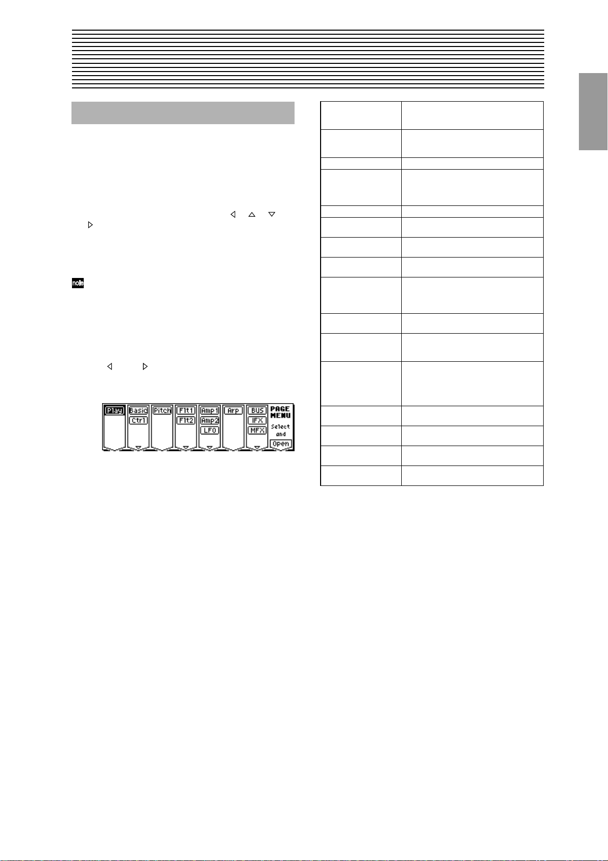
PROG PAGE MENU
Use the following procedure to select the desired page
within the mode.
Press the [MENU] key to access the “PAGE MENU.”
The “PAGE MENU” will show an abbreviated name for
each page.
Use the [F1]–[F7] keys at the bottom of the page to select
the desired page. Pressing the same key will move downward. You can also move by using the [ ], [ ], [ ],
[ ] keys.
Press the [F8] (“Open”) key to access the page.
If the selected page contains two or more tab pages, press
the nearest [F1]–[F7] key below the tabs to select the
desired tab page.
Other ways to select a page
• You can also move to the desired page by holding down
the [MENU] key and using numeric keys [0]–[9] to enter
a two-digit page number. For example if you wish to
access the 5.3: Ed-LFOs page, hold down the [MENU]
key and consecutively press numeric keys [5] and then
[3].
• By holding down the [MENU] key and using the cursor
keys [ ](–) or [ ](+), you can step through the pages
forward or backward in the order of 1.1
etc.
2.1→2.2→3.1,
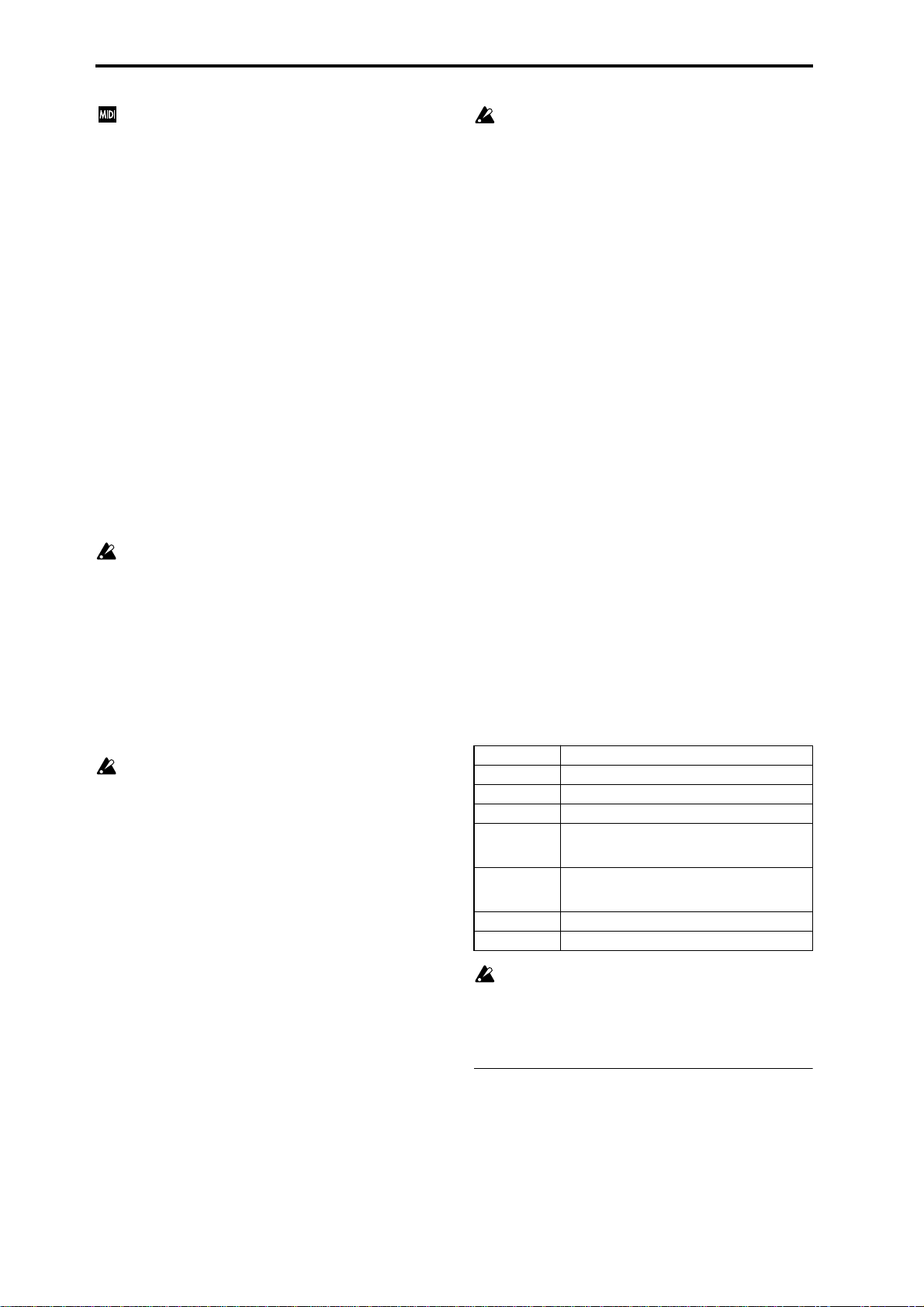
Play 1.1: Play Select and play programs. Use the Perfor-
Basic 2.1: Ed-Basic Set basic program parameters such as
Ctrl 2.2: Ed-Ctrl Controller settings. (
OSC 2.3: Ed-OSC This will be displayed when you select bank
Pitch 3.1: Ed-Pitch Pitch settings. Pitch EG settings. (
Flt1 4.1: Ed-Filter1 Filter 1 (tone) settings. Filter EG settings.
Flt2 4.2: Ed-Filter2 Filter 2 (tone) settings. Filter EG settings.
Amp1 5.1: Ed-Amp1 Amp 1 (volume) settings. Amp EG, pan
Amp 5.1: Ed-Amp This will be displayed when you select bank
Amp2 5.2: Ed-Amp2 Amp 2 (volume) settings. Amp EG, pan
EG 5.2: Ed-EGs This will be displayed when you select bank
LFO 5.3: Ed-LFOs Type and speed settings etc. for the two
Arp 6.1: Ed-Arp. Arpeggiator settings. (Shared with 1.1: Play
BUS 7.1: Ed-BUS Select the BUS and master effect send
IFX 7.2: Ed-InsertFX Insert Effect routing, selection and settings.
MFX 7.3: Ed-Mas-
terFX
mance Editor for easy editing, and to do
simple editing of arpeggio patterns. (
Oscillator and Multisample, and make settings for the Audition function. (
☞p.9)
I–F if the optional EXB-MOSS is installed.
OSC settings for the MOSS tone generator.
☞p.10)
(
☞p.14)
(
(
☞p.19)
(position) settings. (
I–F if the optional EXB-MOSS is installed.
Amp (volume) settings. Amp EG, pan (position) settings.
(position) settings. (
I–F if the optional EXB-MOSS is installed.
EG settings.
LFOs provided for each oscillator. (Make
settings in the pitch, filter, and amp pages
to specify the depth of the LFO settings you
make here.) (
parameters. You may edit either.) (
level for the oscillator output. (
☞p.28)
(
Master Effect selection and settings. Master
EQ settings. (
☞p.19)
☞p.22)
☞p.23)
☞p.29)
☞p.2)
☞p.5)
☞p.10)
☞p.24)
☞p.26)
PROG
1.1
2.12.22.33.14.14.25.15.25.36.17.17.27.3
Page 9
PROG 1.1: Play
In this display page you can select and play programs.
All MIDI data in PROG 1.1: Play is transmitted and
received on the Global MIDI Channel (
1a).
1.1–1: Program
1.1–1a
1.1–1b
1.1–1a: Bank, Program Select, Category , Cat. Hold,
10’s Hold,
Bank (Bank Select)
[INT-A…INT-F, G, g(1)...g(9), g(d), EXB-A...EXB-H]
This is the program bank display.
Use the [BANK], [A]–[H] keys to select the bank.
To select programs from internal banks INT-A–g(d), press
the [BANK] key to make the INT/EXB indicator go dark,
and use the [A]–[G] keys to select the bank.
For bank G, the following banks will be selected successively each time you press the BANK [G-GM] key.
G→g(1)→g(2)→g(3)→g(4)→g(5)→g(6)→g(7)→g(8)→g(9)→
g(d)→G
Bank INT-F can be selected if you have installed the
separately sold EXB-MOSS option. When installed, the
128 EXB-MOSS programs will be available.
To select programs from external banks EXB-A–EXB-H,
press the [BANK] key to make the INT/EXB indicator light,
and use the [A]–[H] keys to select the bank.
Banks EXB-A–H are normally used when a separately
sold EXB-PCM series option is installed.
The program area consists of several banks. INT-A–E and
EXB-A–H each contain 128 programs (total 1,664), which
can be overwritten (RAM). Additionaly, there is a nonrewritable (ROM) bank, G (containing GM2 capital programs, banks g(1)–g(9)[variation programs], and bank g(d)
[drums]). (For a list of the factory-set programs, refer to the
separate VNL.)
INT-A...INT-D (I-A...I-D) for preloaded programs
INT-E (I-E) User programs, such as programs
that use multisamples created in
Sampling mode.
INT-F (I-F) (for EXB-MOSS programs)
G GM2 capital program
g(1)–g(9) GM2 variation programs*
g(d) GM2 drums program
EXB-A...EXB-H (E-A...E-H) (for user programs, and EXB-PCM
series programs)
* For banks with no variation sounds, the GM basic sounds
will be recalled. (An * will be added at the beginning of
the program name.)
☞GLOBAL 2.1–
1.1–1c 1.1–1d
Program Select [(I-A…I-F, E-A...E-H)0…127: name,
(G…g(d))1…128: name]
Selects a program. Choose this parameter, and use the
[INC], [DEC] keys, numeric keys [0]–[9], and the [VALUE]
dial to select a program.
You can select programs by category, or by using “10’s
Hold.” (
☞“Category,” “Cat. HOLD,” “10’s HOLD”)
You can also select a program by sending a MIDI program change from a connected external MIDI device.
(
☞p.221)
Category [00...15: Name]
Selects the program category.
All programs are classified into one of sixteen categories.
You can select the desired category, and then choose programs from that category.
For the procedure of selecting programs from a category,
refer to “Cat. HOLD” and “Select by Category.”
To assign a category to each program, use the “Write
Program” (1.1–1d) dialog box. To change the name of a
category, use “Category Name Prog. 00–07, 08–15”
(
☞GLOBAL 4.1–1/2).
Cat. HOLD (Category Hold)
1 Press the [./HOLD] key to display . The cate-
gory will be held (fixed ).
2 Use “Category” to select the desired category.
3 Choose “Program Select,” and use the [INC], [DEC] keys
or the [VALUE] dial to select programs sequentially
within the specified category.
4 To cancel, press the [./HOLD] key twice to turn off the
display.
If you press the [./HOLD] key in PROG 1.1: Play, the
selection will cycle in the order of →
→ Cancel.
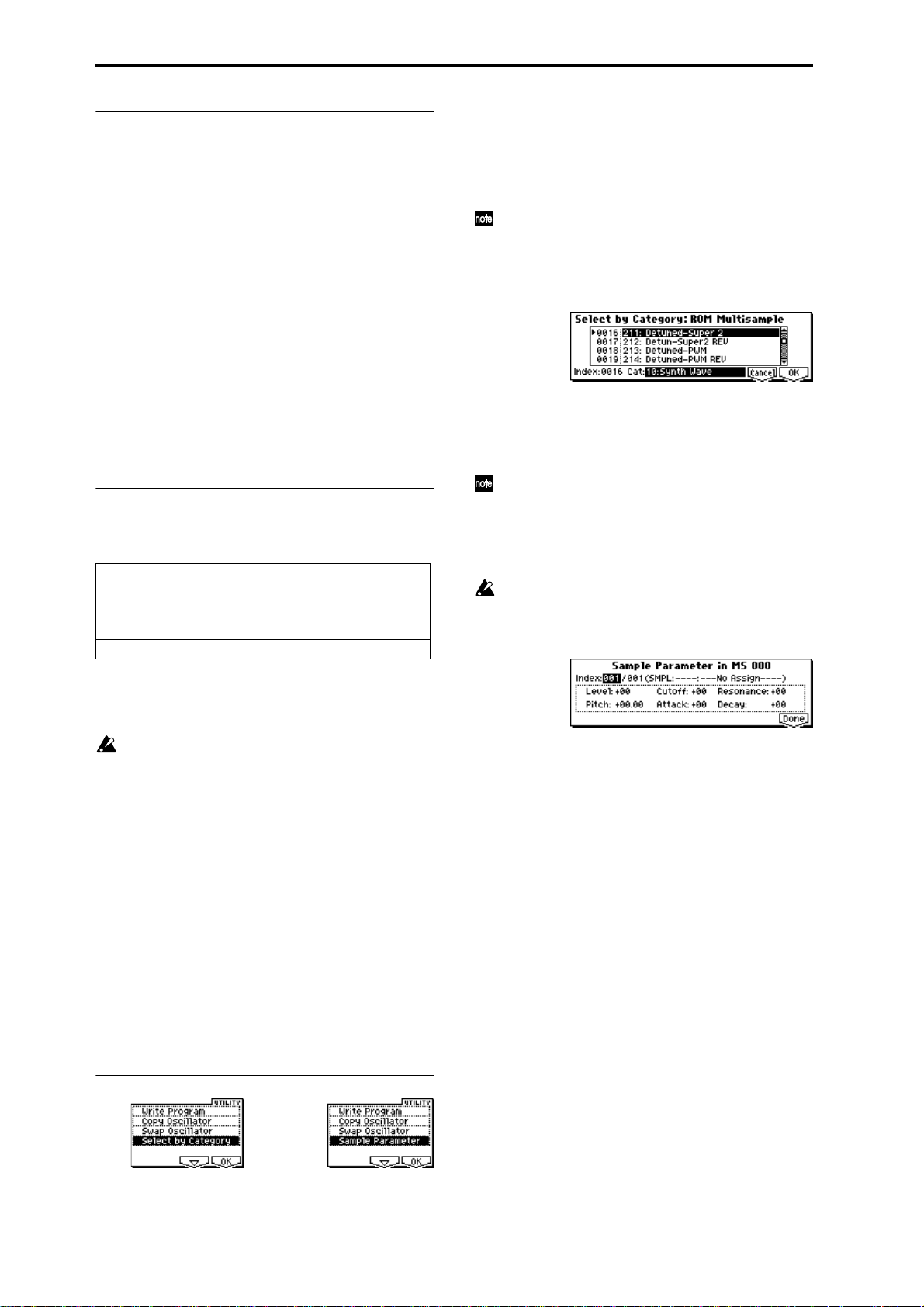
Select by Category
1 Press the [F8] (“UTILITY”) key to access the Utility
menu.
2 Press the [F7] key or the [ ], [ ] keys to choose “Select
by Category,” and then press the [F8] key. The Select Program by Category dialog box will appear. The programs
in that category will be shown in the framed list.
3 Select “Cat,” and use the [INC], [DEC] keys or [VALUE]
dial to choose the category that includes the program you
wish to select.
4 Use the [ ], [ ] keys to select a program from the list.
Alternatively, you can use the [ ], [ ] keys to select
“Index,” and use the [INC], [DEC] keys or [VALUE] dial
to make your selection.
At this time, you can play the keyboard etc. of a connected MIDI device to hear the selected sound.
5 Press the [F8] (“OK”) key to finalize your selection, or
press the [F7] (“Cancel”) key to cancel your selection.
10’s HOLD
1 Press the [./HOLD] key to display .
The ten’s place of the program number will be held
(fixed).
2
Page 10
2 When you press a numeric key [0]–[9], the one’s place of
the program number will be input with a single action.
3 You can use the [INC], [DEC] keys to change the ten’s
place.
4 To cancel, press the [./HOLD] key to turn off the
display.
(Tempo) [040...240, EXT]
This sets the tempo of the arpeggiator. The tempo can also
be adjusted by the REALTIME CONTROLS C-mode
[TEMPO] knob.
A display of EXT indicates that the “MIDI Clock” setting
(GLOBAL 2.1–1a) has been set to External, and that the
arpeggiator will synchronize to MIDI Clock messages
received from an external MIDI device.
This parameter is linked with “Tempo” (6.1: Ed-Arp).
1.1–1b: Program Information
This displays the functions that are assigned to the “SW1,”
“SW2,” and REALTIME CONTROLS B mode [ASSIGN-
ABLE 1]–[ASSIGNABLE 4] knobs for the selected program.
Y ou can also use the [BANK] and [A]–[H] keys to select
a bank.
It is not possible to write to banks INT-G–g(d). If you
have edited a program from banks G–g(d) and wish to
write it, you must write to banks INT-A–INT-E, EXB-A–
EXB-H.
5 If you wish to change the program name, press the [F5]
(“Name”) key to move to the text dialog box, and input
the name. (
6 To write the program, press the [F8] (“OK”) key. To can-
cel without writing, press the [F7] (“Cancel”) key.
When you press the [WRITE] key, the Update Program
dialog box will appear. Here too, you can write to the
currently selected program.
☞BG p.38)
Select by Category
You can select a program by category. (☞p.2)
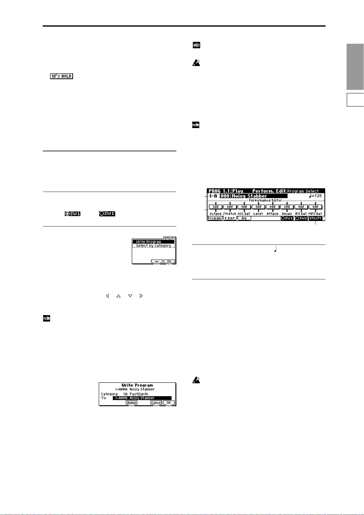
1.1–2: P.Edit (Performance Editor)
PROG
1.1
2.12.22.33.14.14.25.15.25.36.17.17.27.3
■ 1.1–1c: SW1, SW2
This turns the SW1 and SW2 functions assigned to the program on ( ) or off ( . (
■ 1.1–1d: UTILITY
Use the following procedure to select the desired utility.
1 Press the [F8] (“UTILITY”) key to access the Utility
menu.
2 Press the [F7] key or the [ ], [ ], [ ], [ ] keys to select
the desired utility.
3 Press the [F8] (“OK”) key to access the dialog box.
Utilities up to number 10 can also be selected by holding down the [ENTER] key and pressing the corresponding numeric key [0]–[9] to access the dialog box.
☞2.2: Ed-Ctrl)
Write Program
If you wish to keep a program, be sure to write it into memory.
An edited program cannot be recovered if you fail to write it
before turning off the power or selecting another program.
1 Select “Write Program” to access the dialog box.
2 The upper line shows the bank name and program name.
3 In “Category,” specify the category of the program that
you are writing. The category selected here can be used
to find this program when selecting a program in Program, Combination and Multi modes. With the factory
settings, the program categories have been given the
names of instruments etc., but you can use “Category
Name Prog.00–07, 08–15“ (GLOBAL 4.1–1/2) to modify
these category names.
4 Press “To” to specify the writing destination.
1.1–2a
1.1–2b
1.1–2c
1.1–2a: Bank, Program Select, (Tempo)
Select a program. The bank, number, and name of the program will be displayed (
☞p.2). “ ” sets the tempo. (☞p.3)
1.1–2b: Performance Editor
The Performance Editor lets you edit major program parameters without moving to the PROG 2.1–7.3 Ed (Edit) pages.
This edits multiple program parameters within the currently
selected program, allowing you to make broad adjustments
easily.
You can use the Performance Editor when you wish to
adjust the depth of effects etc. while you are playing, or to
make the initial rough settings to begin the process of creating a new sound.
Editing that you do here will affect the values of the program parameters in the edit buffer.
If you wish to keep the results of your editing, you must
write (save) the program (
Editing done using the Performance Editor will occur
within the range of the corresponding parameter. If
after using the Performance Editor to modify a value,
you move to another page or mode and then return, the
sound will remain in its edited state but the value
shown in the LCD screen by the Performance Editor
will be +00. You may do further editing from this state
if you wish.
Since editing done using the Performance Editor is not
as detailed as conventional editing, the balance
between parameters may be lost. If this occurs, use 2.1:
Ed-Basic–7.3: Ed-MasterFx to make fine adjustments.
☞BG p.37).
3
Page 11
If the “Exclusive” (GLOBAL 2.1–1b) setting is checked,
MIDI exclusive parameter changes will be transmitted
whenever you operate the Performance Editor. If these
messages are received by a TRITON-Rack whose
“Exclusive” setting is checked, the Performance Editor
corresponding to that message will be modified.
Octave [–03...+00...+03]
An adjustment of +01 will raise the pitch one octave.
An adjustment of –01 will lower the pitch one octave.
This setting cannot adjust the pitch higher than 4' (feet) or
lower than 32' (feet).
Stretch (Pitch Stretch) [–12...+00...+12]
This simultaneously adjusts the Transpose and Tune of the
oscillator. This lets you produce a variety of tonal changes
and variations without loosing the character of the original
sound.
At the +00 setting, the value of the program parameters will
be unchanged.
An adjustment of +01 will lower the Transpose value by 1,
and simultaneously raise the Tune value by 100.
An adjustment of –01 will raise the Transpose value by 1,
and simultaneously lower the Tune value by 100.
However, it is not possible for the Transpose value to exceed
the range of ±12, nor the Tune value to exceed the range of
±1200.
This Performance Edit function cannot be used for
bank I–F.
OSC Bal (OSC Balance) [–10…+00…+10]
This adjusts the level balance between oscillators 1 and 2.
At the +00 setting, the value of the program parameters will
be unchanged.
Positive (+) settings will lower the oscillator 2 level.
With an adjustment of +10, the oscillator 2 level will be 0.
The oscillator 1 level will not change.
Negative (–) settings will lower the oscillator 1 level.
With an adjustment of –10, the oscillator 1 level will be 0.
The oscillator 2 level will not change.
For programs whose “Mode (Oscillator Mode)” (2.1–1a)
setting is Single, oscillator 2 will not sound. Only the
level of oscillator 1 will change. For a Drums program,
this performance editor will have no effect.
Level (Amp Level) [–10…+00…+10]
This adjusts the amp level.
With an adjustment of +00, the value of the program parameters will be unchanged.
Positive (+) settings will increase the amp level above the
value that was set.
With an adjustment of +10, the amp level will be 127 (maximum).
Negative (–) settings will lower the amp level below the
value that was set.
With an adjustment of –10, the amp level will be 0.
Attack (Attack Time) [–10…+00…+10]
This adjusts the attack times of the filter EG and amp EG.
With an adjustment of +00, the value of the program parameters will be unchanged.
Positive (+) settings will lengthen the attack times beyond
the values that were set.
With an adjustment of +10, the attack times will be 90.
Negative (–) settings will shorten the attack times.
With an adjustment of –10, the attack times will be 0.
When you modify “Attack Time,” the EG Start Level,
Attack Level, Start Level Modulation, and Attack Time
Modulation of the amp EG will also be adjusted simultaneously, to allow the maximum effect to be obtained.
Decay (Decay Time) [–10…+00…+10]
This adjusts the Decay Time and Slope Time of the filter EG
and amp EG.
With an adjustment of +00, the value of the program parameters will be unchanged.
Positive (+) settings will lengthen the Decay Time and Slope
Time beyond the values that were set. With an adjustment of
+10, the times will be 99.
Negative (–) settings will shorten the Decay Time and Slope
Time. With an adjustment of –10, the times will be 0.
IFX Bal (IFX Balance) [–10…+00…+10]
This adjusts the “W/D(Wet/Dry)” setting of insertion
effects 1–5 as a whole.
With an adjustment of +00, the value of the program parameters will be unchanged.
Positive (+) settings will raise the Wet levels above the program setting, and lower the Dry levels. With an adjustment
of +10, the setting will be “Wet.”
Negative (–) settings will lower the Wet levels below the
program setting, and raise the Dry levels. With an adjustment of –10, the setting will be “Dry.”
MFX Bal (MFX Balance) [–10…+00…+10]
This adjusts the master effect “Rtn1 (Return1)” and “Rtn2
(Return2)” (7.3–1a) settings as a whole.
With an adjustment of +00, the value of the program parameters will be unchanged.
Positive (+) settings will raise the return levels above the
program setting.
With an adjustment of +10, the setting will be 127 (maximum).
Negative (–) settings will lower the return levels below the
program setting.
With an adjustment of –10, the setting will be 0.
Octave Octave of OSC 1 and 2
Stretch Transpose and Tune of OSC 1 and 2
OSC Bal High Level and Low Level of OSC1 and 2
Level Amp1 Level, Amp2 Level
Attack Amp EG Attack Time, Start Level, Attack Level,
Decay AmpEG Decay Time, Slope Time of Amp 1 and 2,
IFX Bal W/D(Wet/Dry) balance of the IFX1/2/3/4/5 effects
MFX Bal Master Effect RTN1, 2(Return1, 2)
For the bank I–F programs that can be used when the
separately sold EXB-MOSS option is installed, different
program parameters will be adjusted.
☞EXB-MOSS owner’s manual & p.251 “EXB-MOSS
(
option”)
■ 1.1–2c: UTILITY
☞“Write Program,” “Select by Category” (1.1–1d)
Level Modulation St, Time Modulation At of Amp 1
and 2, and Filter EG Attack Time of Filter 1 and 2
Filter EG Decay Time and Slope Time of Filter 1
and 2
4
Page 12
1.1–3: Arp (Arp. Play)
While arpeggiator parameters are for the most part edited in
PROG 6.1: Ed-Arp., Some major parameters can be edited
here as well. When you are playing in PROG 1.1: Play, you
can edit the arpeggiator in realtime, such as changing the
arpeggio pattern etc.
You can also use the REALTIME CONTROLS C-mode
[TEMPO], [ARP-GATE], and [ARP-VELOCITY] knobs to
edit the arpeggio in realtime (
1.1–3a
☞BG p.21).
1.1–3b
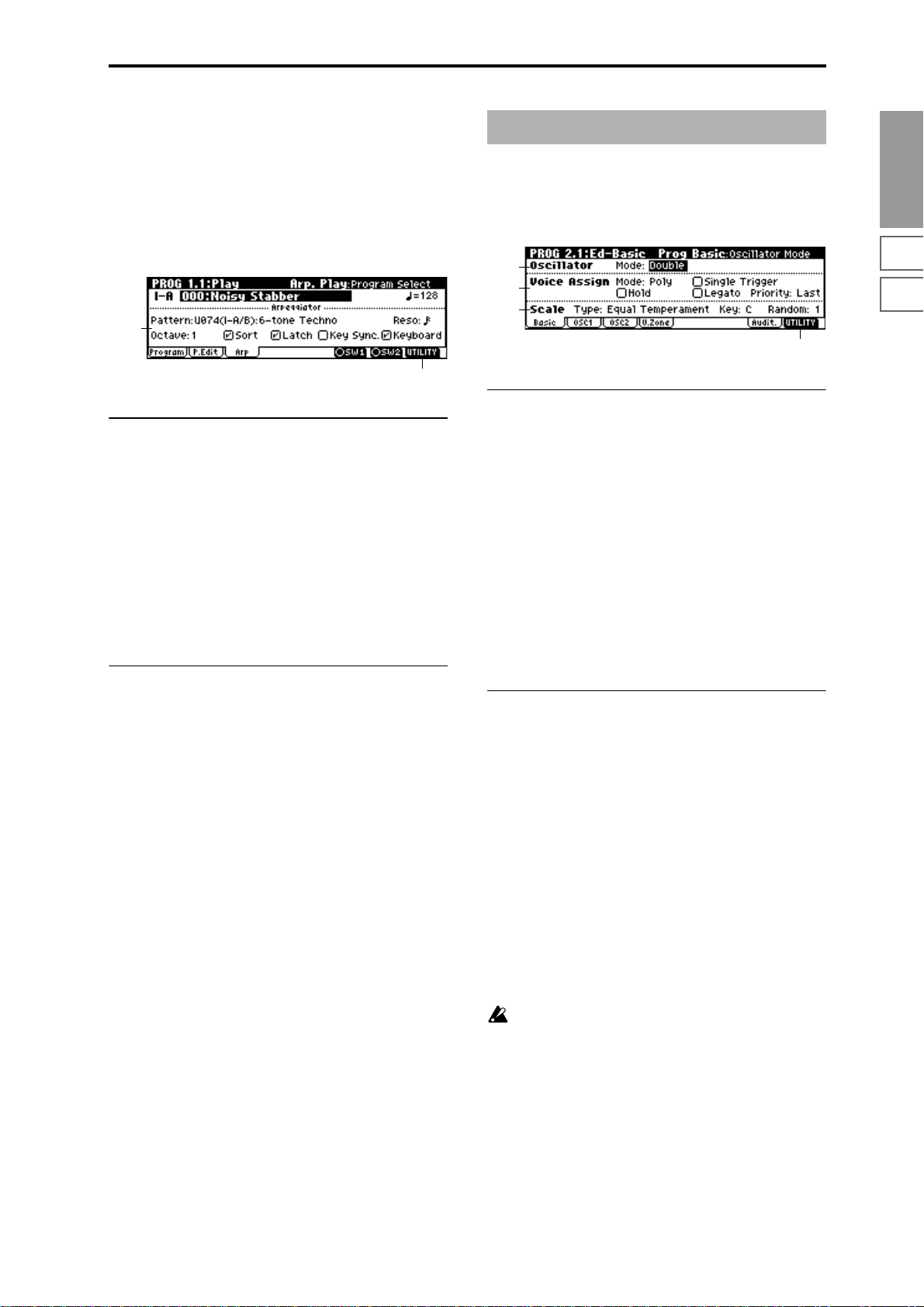
PROG 2.1: Ed–Basic
Make basic settings for the oscillator(s) that will be used.
2.1–1: Basic (Prog Basic)
2.1–1a
2.1–1b
2.1–1c
2.1–1d
2.1–1a: Oscillator
PROG
1.1
2.12.22.33.14.14.25.15.25.36.17.17.27.3
1.1–3a: Arpeggiator
Pattern [P000...P004, U000(I-A/B)...U327(E–H)]
Reso (Resolution) [ , , , , , ]
Octave [1, 2, 3, 4]
Sort [Off, On]
Latch [Off, On]
Key Sync. [Off, On]
Keyboard [Off, On]
Make settings for the program arpeggiator (☞“PROG: EdArp.”). These parameters can also be set from 6.1: Ed-Arp.
Arp.” (
☞6.1–1a).
■ 1.1–3b: UTILITY
☞“Write Program,” “Select by Category” (1.1–1d)
Mode (Oscillator Mode) [Single, Double, Drums]
Specifies the basic program type; whether it will use one or
two oscillators, or a drum kit.
Single: The program will use one oscillator (Oscillator 1,
Filter 1, Amplifier 1). In this case the program will have a
maximum of 60-note polyphony.
Double: The program will use two oscillators (Oscillator 1/
2, Filter 1/2, Amplifier 1/2). Allowing you to create more
complex sounds. In this case the program will have a maxi-
mum of 30-note polyphony.
Drums: The program will use one oscillator (as when Sin-
gle is selected), but Oscillator 1 will be assigned a drum kit
instead of a multisample. In this case the program will have
a maximum of 60-note polyphony.
2.1–1b: Voice Assign
Mode (Voice Assign Mode) [Poly, Mono]
Poly: The program will play polyphonically, allowing you
play chords.
Mono: The program will play monophonically, producing
only one note at a time.
Hold [Off, On]
On (Checked): Hold is On. Even when you take your finger
off of the key, the note will continue sounding as if it continued to be held. Unless the “Amp1 EG”, “Amp2 EG” (5.1–3a,
5.2–3) “S (Sustain Level)” is set to 0, the sound will continue
playing.
This is ideal for playing drum sounds, and when you set
“Mode (Oscillator Mode)” (2.1–1a) to Drums, you should
turn Hold On.
Off (Unchecked): Hold is Off. Except for drum programs,
you should normally set Hold Off.
If you turn “Hold” On for a drum program, keys of the
selected drum kit whose “Enable Note Off” parameter
(GLOBAL 5.1–3a) is unchecked will be set to Hold On.
Keys that are checked will be set to Hold Off. If you
select Hold Off, the keys will be set to Hold Off regardless of their “Enable Note Off” setting.
Single Trigger [Off, On]
This is available when the “Mode (Voice Assign Mode)” setting is set to Poly.
On (Checked): When the same note is played repeatedly, the
previous note will be silenced before the next note is
sounded, so that the notes do not overlap.
5
Page 13

Legato [Off, On]
This is available when the “Mode (Voice Assign Mode)” setting is set to Mono.
On (Checked): Legato is on. When multiple note-on’s occur,
the first note-on will retrigger the sound, and the second and
subsequent note-on’s will not retrigger.
Off (Unchecked): Legato is off. Notes will always be retriggered when note-on occurs.
When legato is on, multiple note-on’s will not retrigger the
voice. If one note is already on and another note is turned on,
the first voice will continue sounding. The oscillator sound,
envelope, and LFO will not be reset, and only the pitch of the
oscillator will be updated. This setting is effective for wind
instrument sounds and analog synth-type sounds.
When legato is off, multiple note-on’s will retrigger the
voice at each note-on. The oscillator sound, envelope, and
LFO will be reset (and retriggered) according to the settings
of the program.
If “Legato” is checked, certain multisamples or keyboard locations may produce an incorrect pitch.
Priority [Low, High, Last]
This parameter is valid when “Mode (Voice Assign Mode)”
is set to Mono.
It specifies which note will be given priority to play when
two or more notes are played simultaneously.
Low: Lowest note will take priority.
High: Highest note will take priority.
Last: Last note will take priority.
2.1–1c: Scale
Type (Scale Type)
[Equal Temperament…User Octave 15]
Select the basic scale for the internal tone generator.
Equal Temperament: This is the most widely used scale,
where each semitone step is spaced at equal pitch intervals.
Pure Major: In this temperament, major chords of the
selected tonic will be perfectly in tune.
Pure Minor: In this temperament, minor chords of the
selected tonic will be perfectly in tune.
Arabic: This scale includes the quarter-tone scale used in
Arabic music.
Pythagoras: This scale is based on ancient Greek musical
theory, and is especially effective for playing melodies.
Werkmeister (Werkmeister III): This is an equal tempered
scale that was used since the later Baroque period.
Kirnberger (Kirnberger III): This scale was created in the
18th century, and is used mainly to tune harpsichords.
Slendro: This is an Indonesian gamelan scale in which an
octave consists of five notes.
When “Key” is set to C, use the C, D, F, G and A notes.
(Other keys will sound equal-tempered pitches.)
Pelog: This is an Indonesian gamelan scale in which an
octave consists of seven notes.
When “Key” is set to C, use the white keys. (The black keys
will sound the equal tempered pitches.)
Stretch: This tuning is used for acoustic pianos.
User All Notes: This is the full-range scale (C–1 – G9) that
was specified in “User All Notes Scale” (GLOBAL3.1–2a).
User Octave 00–15: These are the single-octave scales that
were specified in “User Octave Scale” (GLOBAL3.1–1a).
Key [C…B]
Select the tonic note of the specified scale.
This setting is not valid for Equal Temperament, Stretch,
and User All Notes Scale.
Random [0…7]
As this value is increased, a greater variance will be applied
to the pitch when each note is sounded. Normally you will
set this to 0. This parameter is used when simulating instruments that have natural instability in pitch, such as tapemechanism organs or acoustic instruments.
If a scale other than Equal T emperament is selected, the
combination of the selected scale and the “Key” setting
may skew the tuning of the base key (for example
A=440 Hz). If this occurs, use “Master T une” (GLOBAL
1.1–1a) to correct the pitch.
■ 2.1–1d: UTILITY
☞“Write Program” (1.1–1d)
For details on how to select the desired utility function, refer
to “PROG 1.1–1d: UTILITY.”
Copy Oscillator
This function copies oscillator settings to the currently
selected program.
1 Select “Copy Oscillator” to access the dialog box.
2 In “From,” select the oscillator that you wish to copy and
the copy source program. You can use the [BANK] and
[A]–[H] keys to select the bank.
3 In “To,” select the copy destination oscillator.
4 To execute the Copy Oscillator operation, press [F8]
(“OK”) key. To cancel, press the [F7] (“Cancel”) key.
Swap Oscillator
This command exchanges the settings of oscillators 1 and 2.
1 Select “Swap Oscillator” to access the dialog box.
2 To execute the Swap Oscillator operation, press [F8]
(“OK”) key. To cancel, press the [F7] (“Cancel”) key.
This can be selected only if “Mode (Oscillator Mode)”
(2.1–1a) is Double.
6
Page 14
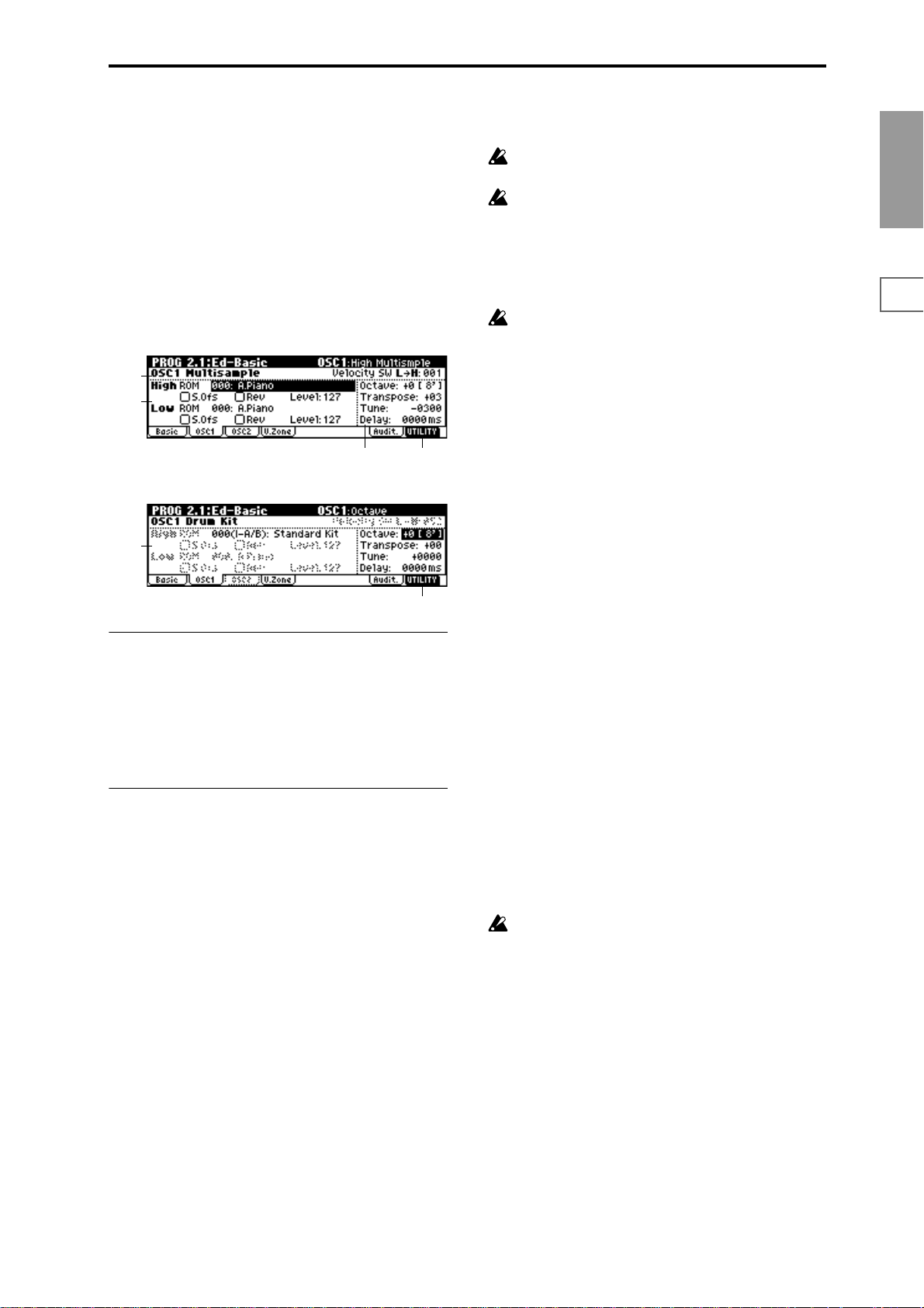
2.1–2: OSC1
The multisample(s) (waveform) or drum kit on which the
program will be based can be selected here for oscillator 1
and/or oscillator 2.
Internal ROM contains 425 different multisamples (preset
multisamples) and 153 drum kits. By selecting a RAM multisample, you can use a multisample that you created in Sampling mode or that you loaded in Disk mode. If an EXBPCM series option has been installed, you will be able to
select multisamples from the installed option.
The following illustration shows a LCD screen where
“Mode (Oscillator Mode)” (2.1–1a) has been set to Double.
If this is set to Single, the OSC2 page parameter will not
appear and cannot be set.
2.1–2a
2.1–2b
2.1–2c
The following illustration shows the display when “Mode
(Oscillator Mode)” (2.1–1a) has been set to Drums.
2.1–2d
2.1–2a: OSC1 Multisample
Velocity SW L→H [001...127]
The oscillator 1 High and Low multisamples that you specify in “High, Low” (2.1–2b) will be switched at the velocity
value that you specify here. When a note with a velocity
higher than this value is received from a connected MIDI
device, the High multisample will sound.
2.1–2b: High, Low
Here you can select a multisample.
Y ou can select differ ent multisamples for High and Low, and
use velocity to switch between the two multisamples. Start
Offset, Reverse, and Level can be adjusted independently
for the High and Low multisamples.
High:
High MS Bank [ROM, RAM, EXB* ...]
High Multisample [000...424, 000...999]
Specifies the bank and multisample number of the High
multisample. The multisample you select here will sounded
by velocities greater than the value of the “Velocity SW
L→H” (2.1–2a) parameter. If you do not wish to use velocity
switching, set the value to 001, and select only the High multisample.
ROM: Select a preset multisample.
Use “High Multisample” to select from 000–424.
RAM: Select a multisample that you created in Sampling
mode or that you loaded in Disk mode.
Use “High Multisample” to select from 000–999.
EXB*: Multisamples from a separately sold EXB-PCM series
option board can be selected. “*” will indicate the type of
installed option.
2.1–2e
2.1–2e
The multisample number for “High Multisample” will
depend on the options that are installed.
The EXB* display will differ depending on the type of
option board.
If a program that uses a multisample from a separately
sold EXB-PCM series board is selected, but the necessary multisample is not available because the corresponding EXB-PCM (expansion board) is not installed,
the “High MS Bank” field will indicate “ROM.” In this
case, the program will not sound. By re-selecting the
multisample bank, you can make the program sound.
Each multisample has an upper limit, and may not produce sound when played above that limit.
S.Ofs (High Start Offset) [Off, On]
This specifies the point at which the multisample will begin
sounding. For some multisamples this parameter will have
no effect.
On (Checked): The sound will start from the start offset
location that is pre-determined for each multisample.
However when a RAM bank is selected, this will depend on
the selected multisample. If you select a multisample that
includes one of the following types of sample, checking this
item will cause playback to start from the Loop Start Address.
• A sample that was recorded (sampled) in Sampling
mode
• A sample whose Loop Start Address was edited in
Sampling mode after the sample was loaded in Disk
mode
• A sample whose Loop Start Address was specified
automatically when it was loaded as an AKAI, AIFF, or
WAVE file in Disk mode
Off (Unchecked): The sound will start from the beginning of
the multisample waveform.
Rev (High Reverse) [Off, On]
The multisample will be played in reverse. In the case of
ROM or optional (EXB-PCM series) multisamples that were
originally specified to loop, or in the case of multisamples
that were set to loop in Sampling mode, the multisample
will be played back in “one-shot” reverse mode. If the multisample was originally set to reverse, it will playback without change.
On (Checked): The multisample will playback in reverse.
Off (Unchecked): The multisample will playback normally.
Level (High Level) [0...127]
Specifies the level of the multisample.
Depending on the multisample, high settings of this
parameter may cause the sound to distort when a chord
is played. If this occurs, lower the level.
Low:
Specifies the OSC1 Low multisample.
The Low multisample will sound when the velocity is less
than the “Velocity SW L→H” (2.1–2a) setting.
Low MS Bank
Low Multisample
S.Ofs (Low Start Offset)
Rev (Low Reverse)
Level (Low Level)
☞Refer to the corresponding item in “High.”
PROG
1.1
2.12.22.33.14.14.25.15.25.36.17.17.27.3
7
Page 15
2.1–2c: Octave, Transpose, Tune, Delay
Octave [–2[32’], –1[16’], +0[8’], +1[4’]]
Adjusts the pitch in octave units. The normal octave of the
multisample is 8' (feet).
Transpose [–12…+12]
Adjusts the pitch in semitone steps over a range of ±1
octave.
Tune [–1200…+1200]
Adjusts the pitch of the sample in one-cent steps (a semitone
is 100 cents) over a range of ±1 octave.
Delay [0ms…5000ms, KeyOff]
Specifies a delay time from note-on until the note will
sound.
With a setting of KeyOff, the sound will begin when note-of f
occurs. This is used to create sounds such as the “click” that is
heard when a harpsichord note is released. In this case, set the
“Amp1 EG”, “Amp2 EG” (5.1–3a, 5.2–3) “S (Sustain Level)”
parameter to 0.
2.1–2d: OSC1 Drum Kit
Drum Kit [00(I-A/B)...143(E-H), 144(GM)...152(GM)]
Selects a drum kit.
00(I-A/B)–15(I-A/B): Preloaded Drum kits.
16(E-A)–31(E-A), 32(E-B)–47(E-B), 48(E-C)–63(E-C), 64(E-D)–
79(E-C), 80(E-E)–95(E-E), 96(E-F)–111(E-F), 112(E-G)–127(E-G),
128(E-H)–143(E-H):
(for user drum kits, EXB-PCM series drum kits)
144(GM)–152(GM): Preset drum kits compatible with GM2.
For details on how to select the desired utility function, refer
to “PROG 1.1–1d: UTILITY.”
Select by Category
Selects multisamples by category.
For the procedure, refer to “Select by Category” (
This command is valid if “Mode (Oscillator Mode)”
(2.1–1a) is Single or Double, and you are selecting the
“High MS Bank,” “High Multisample,” “Low MS
Bank,” or “Low Multisample” of OSC1 or OSC2 for
which ROM was selected for “High MS Bank” or “Low
MS Bank.”
☞p.2).
Sample Parameters
This command lets you adjust the sample playback level,
cutoff, resonance, pitch, attack, and decay for each index of a
RAM multisample.
This command is valid if “Mode (Oscillator Mode)”
(2.1–1a) is Single or Double, and you are selecting the
“High MS Bank,” “High Multisample,” “Low MS
Bank,” or “Low Multisample” of OSC1 or OSC2 for
which RAM was selected for “High MS Bank” or “Low
MS Bank.”
The setting will apply to the selected multisample. The
setting will also be used when that multisample is
selected by another oscillator or program.
1 Select “Sample Parameters” to access the dialog box.
Octave [–2[32’], –1[16’], +0[8’], +1[4’]]
Adjusts the pitch in octave units. When using a drum kit, set
the Octave to 8'.
When editing a drum program, you must set this
parameter to 8'. With other settings, the sounds of the
drum kit will be assigned to the wrong notes of the keyboard.
Transpose [–12…+12]
This adjusts the location of the instruments in the selected
drum kit. Unless you need to change this, leave it at 0.
Tune [–1200…+1200]
This adjusts the pitch in one-cent units.
The pitch of each drum kit can be adjusted in GLOB 5.1:
DKit.
Delay [0ms…5000ms, KeyOff]
This specifies a delay time from note-on until the sound will
begin.
With a setting of KeyOff, the sound will begin when noteoff occurs. In this case, set the “Amp1 EG” parameter “S
(Sustain Level)” (5.1–3a) to 0.
■ 2.1–2e. UTILITY
☞“Write Program” (1.1–1d), “Copy Oscillator,” “Swap
Oscillator” (2.1–1d)
2 Index: Specifies the index for which you wish to make
settings. The number following “/” is the total number of
indexes in the selected multisample.
SMPL: Indicates the sample number and name for the
index.
3 For each index, you can make the following settings.
Level: Adjusts the volume. Relative to the settings of
“Level (High, Low Level)” (2.1–2b) and “Level (Amp1, 2
Level)” (5.1–1a, 5.2–1), negative (–) values will decrease
the levels, and positive (+) values will increase the levels.
A setting of +99 will double the volume, and at a setting
of –99 there will be no sound. This parameter is linked to
the “Level” (SMPL 4.1–2a). The value that was specified
in Sampling mode will be displayed here.
Cutoff: Adjusts the filter cutoff. This adjustment will be
added to the value specified for “Frequency” (4.1–1b/1c,
4.2–1) of Filter 1 and 2.
Resonance: Adjusts the resonance level of the filter. This
adjustment will be added to the value specified for “Resonance” (4.1–1b, 4.2–1) of Filter 1 and 2.
Pitch: Adjusts the playback pitch in one-cent steps. A setting of +12.00 raises the pitch one octave, and a setting of
–12.00 will lower the pitch one octave. This parameter is
linked with the parameter “Pitch” (SMPL 4.1–2a). The
value that was specified in Sampling mode will be displayed here.
Attack: Adjust sthe attack times of the filter EG and amp
EG. This adjustment will be added to the “A (Attack
Time)” of “Filter 1 EG,” “Filter 2 EG,” “Amp 1 EG,” and
“Amp 2 EG” (4.1–5a, 4.2–5, 5.1–3a, 5.2–3).
8
Page 16
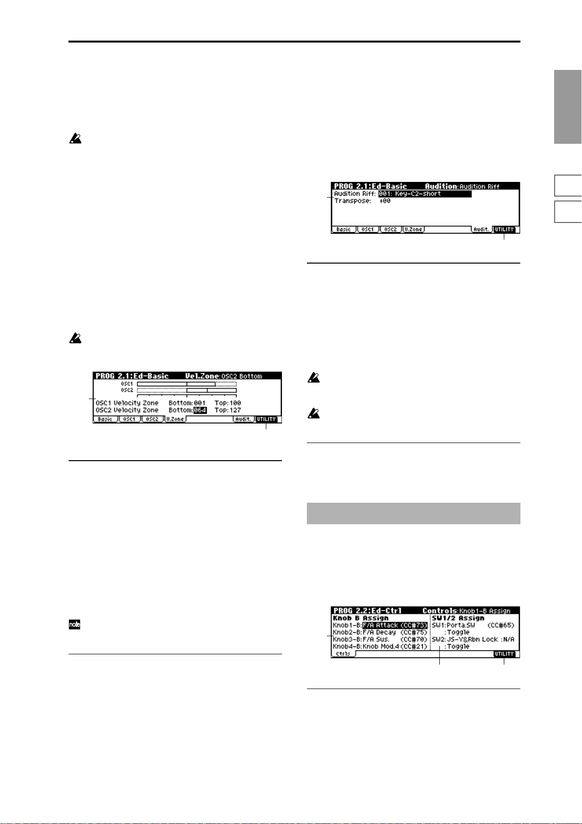
Decay: Adjusts the decay times of the filter EG and amp
EG. This adjustment will be added to the “D (Decay
Time)” of “Filter 1 EG,” “Filter 2 EG,” “Amp 1 EG,” and
“Amp 2 EG.”
4 Press the [F8] (“Done”) key to execute, and close the dia-
log box.
Please be aware that the Compare function is not available for this command.
2.1–3: OSC2
This will appear when “Mode (Oscillator Mode)” (2.1–1a) is
set to Double.
For details on the settings and function of the parameter,
refer to “2.1–2: OSC1.”
2.1–5: Audit. (Audition)
When selecting preloaded programs, you can play back a
pre-specified riff (phrase) that is suitable for the sound of
that program. This is called the Audition function.
When you press the [AUDITION] key to turn it on, the audition riff will play back repeatedly. This allows you to verify a
program or edit it even when a MIDI keyboard is not connected.
Here you can select the audition riff and specify the transposition.
2.1–5a
2.1–5b
PROG
1.1
2.12.22.33.14.14.25.15.25.36.17.17.27.3
2.1–4: V.Zone (Velocity Zone)
Specifies the range of velocities that will sound oscillator 1
and 2. By using these settings in conjunction with the
“Velocity SW L→H” (2.1–2a) setting of each oscillator, you
can specify the velocity ranges for the High and Low multisamples or drum kits.
It is not possible to set the Bottom Velocity greater than
the Top Velocity, nor the Top Velocity less than the Bottom Velocity.
2.1–4a
2.1–4b
2.1–4a: OSC 1/2 Velocity Zone
OSC1 Bottom [001...127]
Sets the minimum velocity value that will sound oscillator 1.
OSC1 Top [001...127]
Sets the maximum velocity value that will sound oscillator
1.
OSC2 Bottom [001...127]
Sets the minimum velocity value that will sound oscillator 2.
2.1–5a: Audition Riff, Transpose
Audition Riff [000: Off...382: Name]
Selects the audition riff. The TRITON-Rack contains 382
audition riffs suitable for a variety of instruments and musical genres. (
With a setting of 000: Off, no riff will be played.
☞“VNL”)
Transpose [–24...+24]
Adjusts the pitch of the audition riff in semitone steps.
It is not possible to change the playback tempo of the
audition riff. Nor is it possible to set the arpeggiator
tempo while the audition riff is playing.
The arpeggiator will be turned off while the audition
riff is playing.
■ 2.1–5b: UTILITY
☞“Write Program” (1.1–1d)
PROG 2.2: Ed–Ctrl
These settings specify the B-mode functions of REALTIME
CONTROLS knobs [1]–[4] in Program mode. and “the functions of the SW1,” the “SW2.”
OSC2 Top [001...127]
Sets the maximum velocity value that will sound oscillator
2.
Y ou can hold down the [ENTER] key and play a note on
a connected MIDI device to input these values.
■ 2.1–4b: UTILITY
☞“Write Program” (1.1–1d), “Copy Oscillator,” “Swap
Oscillator” (2.1–1d)
2.2–1: Ctrls (Controls)
2.2–1a
2.2–1c2.2–1b
2.2–1a: Knob B Assign
Here you can Assign functions (mainly various types of control change) to the B-mode of the REALTIME CONTROLS
knobs [1]–[4] (
List”).
The functions you set here will take effect when you operate
the REALTIME CONTROLS knobs [1]–[4] in B-mode.
☞p.214 “Realtime Control Knobs B Assign
9
Page 17
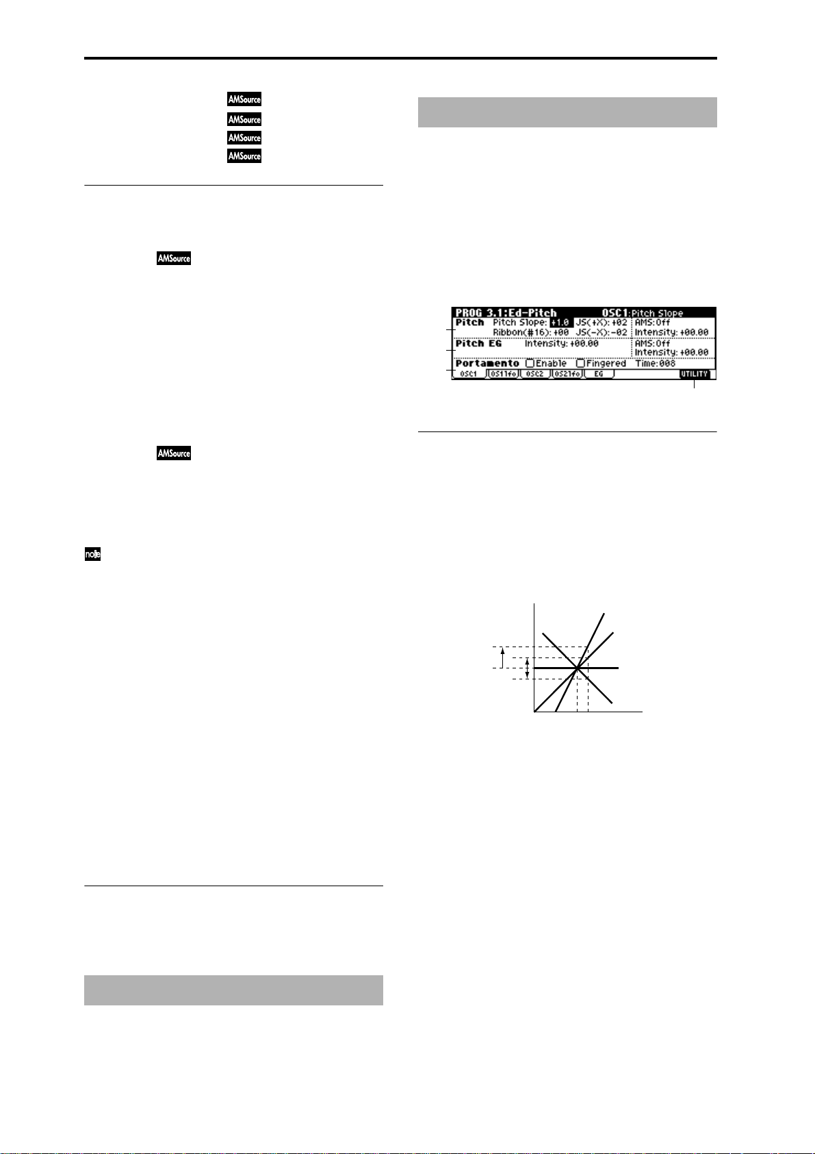
Knob1–B (Knob1–B Assign) [Off, ..., MIDI CC#95]
Knob2–B (Knob2–B Assign) [Off, ..., MIDI CC#95]
Knob3–B (Knob3–B Assign) [Off, ..., MIDI CC#95]
Knob4–B (Knob4–B Assign) [Off, ..., MIDI CC#95]
2.2–1b: SW1/2 Assign
These settings assign functions to [SW1] and [SW2] keys
(
☞p.213 “SW1, SW2 Assign List”).
SW1 Assign [Off, ..., AfterT Lock :N/A]
Here you can assign a function to the “SW1.”
The on/off status of the switch is saved when the program is
written. When you change the function, it will be reset to the
“off” state.
SW1 Mode [Toggle, Momentary]
Specifies the on/off state that will occur when you press the
[F6] (“SW1”) key in 1.1:Play.
Toggle: The key will alternate on/off each time you press
[F6] (“SW1”).
Momentary: The key will be on only while you continue
holding [F6] (“SW1”).
SW2 Assign [Off, ..., AfterT Lock :N/A]
SW2 Mode [Toggle, Momentary]
Here you can assign a function to “SW2.”
The functions that can be assigned to SW2 are the same as
for SW1, with the exception of SW2 Mod. (CC#81) instead of
SW1 Mod. (CC#80).
Although the following values can be selected for “SW1
Assign” and “SW2 Assign,” they will have no effect in
actuality.
Data is compatible between the TRITON-Rack and the
TRITON/TRITONpro/TRITONproX (keyboard models of the TRITON). Programs created on the TRITONRack can be used by a TRITON keyboard model, and
vice versa.
In order to maintain compatibility, you are able to set
these “invalid” parameters on the TRITON-Rack.
N/A indicates Not Available.
Octave Down :N/A
Octave Up :N/A
JS X Lock :N/A
JS+Y Lock :N/A
JS-Y Lock :N/A
Ribbon Lock :N/A
JS X&Rbn Lock :N/A
JS+Y&Rbn Lock :N/A
JS-Y&Rbn Lock :N/A
AfterT Lock :N/A
■ 2.2–1c: UTILITY
☞“Write Program” (1.1–1d), “Copy Oscillator,” “Swap
Oscillator” (2.1–1d)
PROG 3.1: Ed–Pitch
Here you can make pitch modulation settings for oscillators
1 and 2.
3.1–1: OSC1
Specifies how the keyboard location will affect the pitch of
oscillator 1, and select the controller that will modify the
pitch and the depth of this effect. Here you can also specify
the amount of pitch change caused by the pitch EG, and set
the portamento on/off and mode settings.
3.1–1a
3.1–1b
3.1–1c
3.1–1d
3.1–1a: Pitch
Pitch Slope [–1.0…+2.0]
Normally you will leave this at +1.0.
Positive (+) values will cause the pitch to rise as you play
higher on the keyboard, and negative (–) values will cause
the pitch to fall as you play higher on the keyboard.
With a value of 0, there will be no change in pitch, and the
C4 pitch will sound regardless of the keyboard location you
play.
How the Pitch Slope and pitch are related
Pitch
2oct
1oct
1oct
Ribbon (#16) [–12…+12]
Specifies in semitone units how the pitch will change when
CC#16 is received (or when the ribbon controller is pressed
on a TRITON or other instrument connected to MIDI IN).
12 steps equal one octave. With positive (+) values, the pitch
will rise when you press the right half of a ribbon controller.
With negative (–) values, the pitch will fall.
For example, with a setting of +12, pressing the far right
edge of the ribbon controller will raise the pitch one octave.
With a setting of –12, pressing the far right edge of the ribbon controller will lower the pitch one octave.
At the center of the ribbon controller, the original pitch will
remain, so you can use this in conjunction with pressing the
ribbon at its right edge to simulate the “hammering-on”
techniques used by guitarists.
C4 C5
+2
+1
0
–1
Key
PROG 2.3: Ed–OSC
This page will be displayed when you select bank I–F if the
separately sold EXB-MOSS option is installed.
☞EXB-MOSS owner’s manual & p.251 “EXB-MOSS
(
option”)
10
JS (+X) [–60…+12]
Specifies in semitone units how the pitch will change when
a pitch bender message is received (or when the joystick is
moved to the right on a TRITON or other instrument connected to MIDI IN) (
12 steps equal one octave.
☞p.222).
Page 18
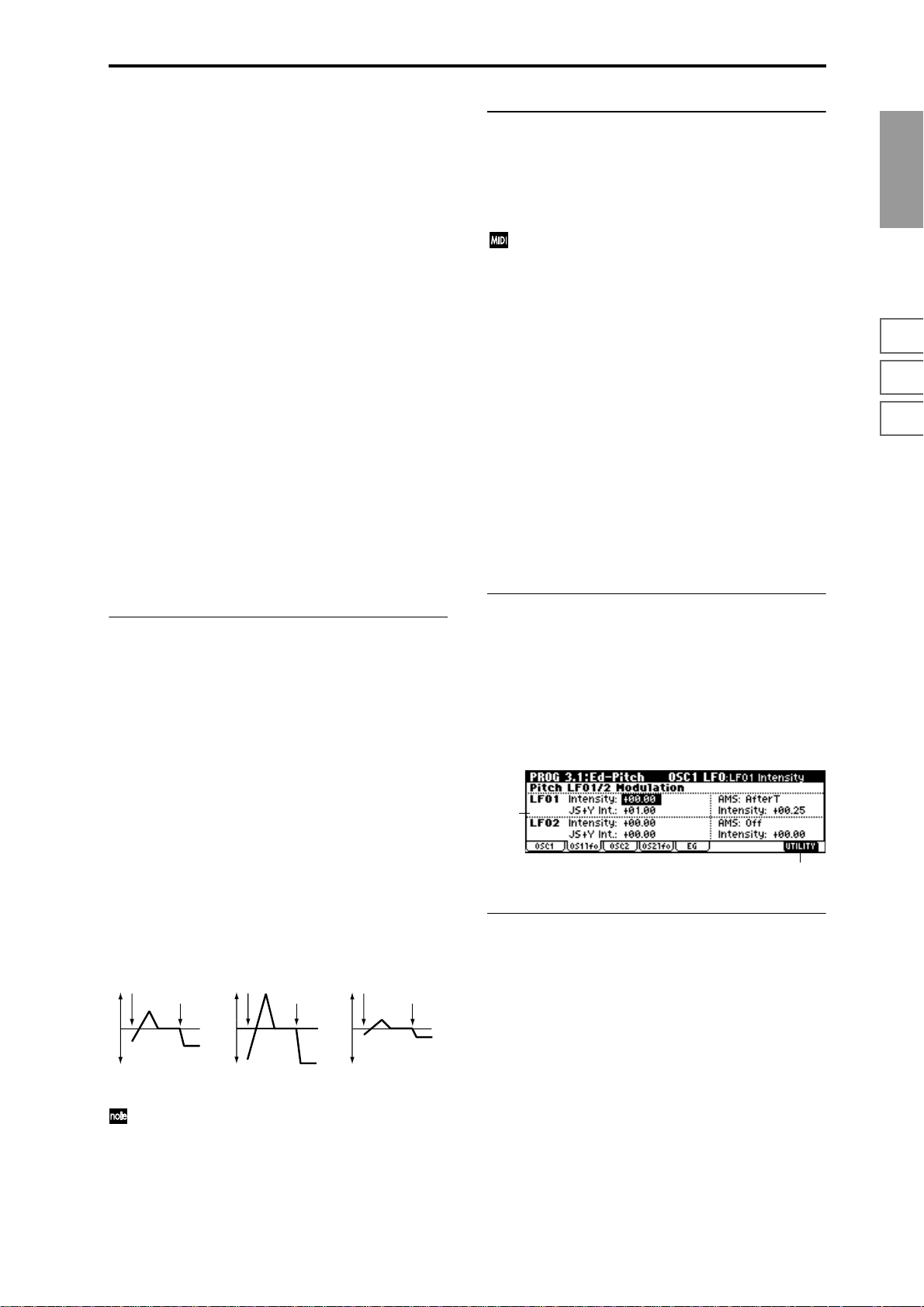
For example, if you set this to +12 and move the joystick all
the way to the right, the pitch will rise one octave above the
original pitch.
JS (–X) [–60…+12]
Specifies in semitone units how the pitch will change when
a pitch bender message is received (or when the joystick is
moved to the left on a TRITON or other instrument connected to MIDI IN). (
☞p.222)
12 steps equal one octave.
For example, if you set this to –60 and move the joystick all
the way to the left, the pitch will fall five octaves below the
original pitch. This can be used to simulate the downward
swoops that a guitarist produces using the tremolo arm.
AMS (Pitch AMS) [Off, (FEG, AEG, EXT)]
Selects the source that will modulate the pitch of oscillator 1
(
☞p.206 “AMS List”).
Intensity (AMS Intensity) [–12.00…+12.00]
Specifies the depth and direction of the effect produced by
“AMS (Pitch AMS).”
With a setting of 0, no modulation will be applied. With a
setting of 12.00, the pitch will change up to one octave.
For example, if you set “AMS (Pitch AMS)” to AfterT and
press down on the keyboard of a connected MIDI instrument, the pitch will rise if you have set this parameter to a
positive (+) value, or will fall if you have set this parameter
to a negative (–) value. The range is a maximum of one
octave. (
☞p.208)
3.1–1b: Pitch EG
Intensity [–12.00…+12.00]
Specifies the depth and direction of the modulation that the
pitch EG specified in “EG (Pitch EG)” (3.1–5) page will
apply to the pitch.
With a setting of 12.00, the pitch will change a maximum of
±1 octave.
AMS (Pitch EG AMS) [Off, (KT, EXT)]
Selects the source that will control the pitch modulation
applied by the pitch EG (
☞p.206 “AMS List”).
Intensity (AMS Intensity) [–12.00…+12.00]
Specifies the depth and direction of the effect that “AMS
(Pitch EG AMS)” will have.
For example, if you set “AMS (Pitch EG AMS)” to Velocity
and set this value to +12.00, the velocity will control the
range of pitch change produced by the pitch EG in a range
of ±1 octave (
change will draw closer to the pitch EG levels.
Pitch change (level)
Note-on
Softly played
(Intensity (Pitch EG) setting)
☞p.208). As you play more softly, the pitch
Note-off
Note-on
Note-off
Strongly played with
a positive (+) value
Note-on
Strongly played with a
negative (–) value
Note-off
3.1–1c: Portamento
This turns the portamento effect (smooth change in pitch
from one note to the next) on/off, and specifies how it will be
applied. If SW 1 or 2 are set to Porta.SW(CC#65), turning
SW1 or SW2 on/off will apply portamento (
☞p.206 “AMS
List” SW1 CC#80, SW2 CC#81, Prta.SWCC#65).
Portamento will also be switched when CC#65 (Portamento SW) is received.
Enable (Porta. Enable) [Off, On]
On (Checked): Portamento will be applied.
Off (Unchecked): Portamento will not be applied.
Fingered (Porta. Fingered) [Off, On]
This parameter is available when “Enable (Porta. Enable)” is
checked.
On (Checked): Portamento will be applied when you continue holding the previous note as you press the next note
(legato playing).
Off (Unchecked): Portamento will always be applied,
regardless of how you play.
Time (Porta. Time) [000...127]
This parameter is available when “Enable (Porta. Enable)” is
checked.
This sets the portamento time. Increasing the value will produce a slower change in pitch.
■ 3.1–1d: UTILITY
☞“Write Program” (1.1–1d), “Copy Oscillator,” “Swap
Oscillator” (2.1–1d)
3.1–2: OS1lfo (OSC1 LFO)
Specifies the amount of pitch change produced by LFO1 and
LFO2 for oscillator 1.
3.1–2a
3.1–2b
3.1–2a: Pitch LFO1/2 Modulation
LFO1:
Intensity (LFO1 Intensity) [–12.00…+12.00]
Specifies the depth and direction of the pitch modulation
applied by the OSC 1 LFO1 settings you made in
“OS1LFO1” page (5.3–1).
With a setting of 12.00, a maximum of ±1 octave of pitch
modulation will be applied. Negative (–) values will invert
the LFO waveform.
PROG
1.1
2.12.22.33.14.14.25.15.25.36.17.17.27.3
“Intensity” and “AMS (Pitch EG AMS)” will be added
to determine the depth and direction of the pitch modulation applied by the pitch EG.
JS+Y Int. (LFO1 JS+Y Int.) [–12.00…+12.00]
Specifies the depth of pitch modulation that will be applied
by OSC1 LFO1 when CC#1 is received (or when the joystick
is moved in the +Y direction on a TRITON or other instrument connected to MIDI IN).
11
Page 19
As this value is increased, moving the joystick in the +Y
direction will cause the OSC1 LFO1 to produce deeper pitch
modulation. With a setting of 12.00 a maximum of ±1 octave
of pitch modulation will be applied. Negative (–) values
will invert the LFO waveform.
AMS (LFO1 AMS) [Off, (PEG, FEG, AEG, KT, EXT)]
Selects the source that will control the depth of pitch modulation produced by the OSC1 LFO1 (
☞p.206 “AMS List”).
Intensity (AMS Intensity) [–12.00…+12.00]
Specifies the depth and direction of the effect that “AMS
(LFO1 AMS)” will have.
With a setting of 0, modulation will not be applied. With a
setting of 12.00, the OSC1 LFO1 will apply a maximum of ±1
octave of pitch modulation. Negative (–) settings will invert
the LFO waveform.
For example, if you set “AMS (LFO1 AMS)” to AfterT and
press down on the keyboard of a connected MIDI instrument, OSC1 LFO1 will apply positive-phase pitch modulation if you have set this parameter to a positive (+) value, or
will apply negative-phase pitch modulation if you have set
this parameter to a negative (–) value.
The “Intensity (LFO1 Intensity),” “JS+Y Int. (LFO1 JS+Y
Int.)” and “AMS (LFO1 AMS)” settings will be added to
determine the depth and direction of the pitch modulation
applied by OSC1 LFO1 (
☞p.208).
LFO2:
Intensity (LFO2 Intensity) [–12.00…+12.00]
JS+Y Int. (LFO2 JS+Y Int.) [–12.00…+12.00]
AMS (LFO2 AMS) [Off, (PEG, FEG, AEG, KT, EXT)]
Intensity (AMS Intensity) [–12.00…+12.00]
Refer to the preceding section “LFO1.”
■ 3.1–2b: UTILITY
☞“Write Program” (1.1–1d), “Copy Oscillator,” “Swap
Oscillator” (2.1–1d)
3.1–5: EG (Pitch EG)
Here you can make settings for the pitch EG, which creates
time-variant changes in the pitch of oscillators 1 and 2.
The depth of pitch change produced by these EG settings on
oscillator 1 (2) is adjusted by “Pitch EG” (3.1–1b, 3.1–3).
3.1–5a
3.1–5b
3.1–5d3.1–5c
3.1–5a: Pitch EG
These settings specify how the pitch will change over time.
L (Level):
These parameters specify the amount of pitch change.
The actual amount of pitch change will depend on the
“Pitch EG” (3.1–1b, 3.1–3) parameter “Intensity.” For example with an “Intensity” setting of +12.00, a “Level” setting of
+99 would raise the pitch one octave, and a “Level” setting
of –99 would lower the pitch one octave.
S (Start Level) [–99…+99]
Specifies the amount of pitch change at note-on.
A (Attack Level) [–99…+99]
Specifies the amount of pitch change when the attack time
has elapsed.
R (Release Level) [–99…+99]
Specifies the amount of pitch change when the release time
has elapsed.
T (Time):
These parameters specify the time over which the pitch
change will occur.
3.1–3: OSC2
Specifies how the keyboard location will affect the pitch of
oscillator 2, and select the controller that will affect the pitch
and specify the depth of control. Here you can also specify
the amount of pitch change produced by the pitch EG, and
set the portamento on/off status and mode. For details on
each parameter, refer to the preceding “3.1–1: OSC1.”
3.1–4: OS2lfo (OSC2 LFO)
Specifies the amount of pitch change produced by LFO1 and
LFO2 for oscillator 1. For an explanation of each parameter,
refer to the preceding “3.1–2: OS1lfo.”
A (Attack Time) [0…99]
Specifies the time over which the pitch will change from
note-on until it reaches the pitch specified as the attack level.
D (Decay Time) [0…99]
Specifies the time over which the pitch will change after
reaching the attack level until it reaches the normal pitch.
R (Release Time) [0…99]
Specifies the time over which the pitch will change from
note-off until it reaches the pitch specified as the release
level.
Time-varying pitch settings (when Pitch EG Intensity = +12.00)
+99 = approximately 1 octave
0 = pitch when
key is held
(sustained)
Start Level
–99 = approximately 1 octave
Note-on
Attack
Time
Attack Level
Decay
Time
Note-off
Release Time
Time
Release Level
12
Page 20
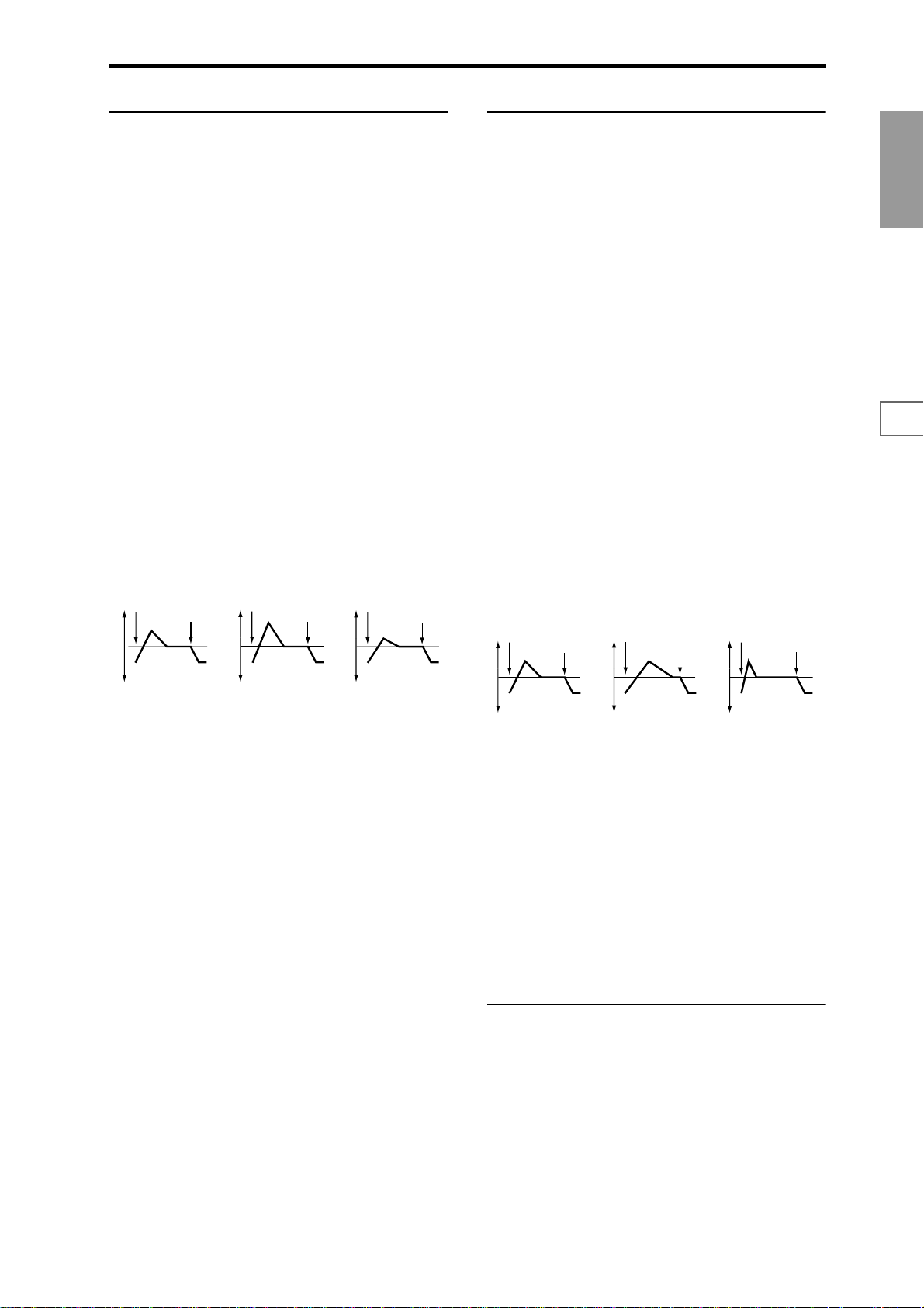
3.1–5b: Level Mod. (Level Modulation)
3.1–5c: Time Mod. (Time Modulation)
These settings allow the pitch EG “L (Level)” parameters to
be controlled by alternate modulation.
AMS1 (Level Mod. AMS1) [Off, (KT, EXT)]
Selects the source that will control the pitch EG “L (Level)”
parameters (
☞p.206 “AMS List”).
I (AMS1 Intensity) [–99…+99]
Specifies the depth and direction of the effect applied by
“AMS1 (Level Mod. AMS1).”
With a setting of 0, the levels specified by “Pitch EG” (3.1–
5a) will be used.
For example, if “AMS1 (Level Mod. AMS1)” is SW1 #80,
pressing the “SW1” to turn it on will change the “Level”
parameters of the Pitch EG. (“SW1/2 Assign”: 2.2–1b) to
SW1 Mod. (CC#80). As the absolute value of “I (AMS1
Intensity)” is increased, the pitch EG levels will change more
greatly when the “SW1” is turned on. The direction of the
change is specified by “S (AMS1 SW Start)” and “A (AMS1
SW Attack).” When the “SW1” ([F6] key) is turned off, the
pitch EG levels will return to their own settings.
If “AMS1” is set to Velocity, increasing the absolute value of
“Intensity” will produce increasingly wider change in pitch
EG levels for strongly-played notes. The direction of the
change is specified by “S (AMS1 SW Start)” and “A (AMS1
SW Attack).” As you play more softly, the pitch change will
draw closer to the pitch EG levels.
Pitch EG change (level) (AMS=SW1/Velocity, Intensity= positive (+) value)
Note-on
Note-off
Note-on
Note-off
Note-on
Note-off
These parameters let you use alternate modulation to control the “T (Time)” parameters of the pitch EG.
AMS (Time Mod. AMS) [Off, (KT, EXT)]
Selects the source that will control the “T (Time)” parameters of the pitch EG (
☞p.206 “AMS List”).
I (AMS Intensity) [–99…+99]
Specifies the depth and direction of the effect that “AMS
(Time Mod. AMS)” will have.
With a setting of 0, the pitch EG times will be just as specified by the “Pitch EG” (3.1–5a) settings.
The alternate modulation value at the moment that the EG
reaches each point will determine the actual value of the EG
time that comes next.
For example, the decay time will be determined by the alternate modulation value at the moment that the attack level is
reached.
When this parameter is set to values of 16, 33, 49, 66, 82, or
99, the specified EG times will speed up as much as 2, 4, 8,
16, 32, or 64 times respectively (or slowed down to 1/2, 1/4,
1/8, 1/16, 1/32, or 1/64 of the original time).
For example if “AMS (Time Mod. AMS)” is set to Velocity,
increasing the absolute value of “I (AMS Intensity)” will
allow strongly-played notes to increase the changes in pitch
EG “T (Time)” values. The direction of the change is specified by “A (AMS SW Attack)” and “D (AMS SW Decay).” As
you play more softly, the pitch EG times will more closely
approach the actual settings of the pitch EG.
Pitch EG changes (Time) (AMS = Velocity, Intensity = positive (+) value)
Note-on
Note-off
Note-on
Note-off
Note-on
Note-off
PROG
1.1
2.12.22.33.14.14.25.15.25.36.17.17.27.3
A note played softly with “S”
set at 0, “A” set to +, and
SW1 turned on (the settings
of 3.1–5a: Pitch EG)
A note played strongly with
“S” set to 0, “A” set to +, and
SW1 turned on
A note played strongly with
“S” set to 0, “A” set to –, and
SW1 turned on
S (AMS1 SW Start) [–, 0, +]
Specifies the direction of change in “S (Start Level)” caused
by “AMS1 (Level Mod. AMS1).” If “I (AMS1 Intensity)” is a
positive (+) value, a setting of + will raise the EG level, and
a setting of – will decrease it. With a setting of 0 ther e will be
no change.
A (AMS1 SW Attack) [–, 0, +]
Specifies the direction of change in “A (Attack Level)”
caused by “AMS1 (Level Mod. AMS1).” If “I (AMS1 Intensity)” is a positive (+) value, a setting of + will raise the EG
level, and a setting of – will decrease it. With a setting of 0
there will be no change.
AMS2 (Level Mod. AMS2) [Off, (KT, EXT)]
I (AMS2 Intensity) [–99…+99]
S (AMS2 SW Start) [–, 0, +]
A (AMS2 SW Attack) [–, 0, +]
Refer to the preceding paragraphs “AMS1 (Level Mod.
AMS1)”–“A (AMS1 SW Attack).”
A note played softly with “A”
set to + and “D” set to +
(settings of 3.1–5a: Pitch EG)
A note played strongly with
“A” set to + and “D” set to +
A note played strongly with
“A” set to – and “D” set to –
A (AMS SW Attack) [–, 0, +]
Specifies the direction in which “AMS (Time Mod. AMS)”
will affect the “A (Attack Time).” With positive (+) values of
“I (AMS Intensity),” a setting of + will cause the time to be
lengthened, and a setting of – will cause the time to be shortened. With a setting of 0 there will be no change.
D (AMS SW Decay) [–, 0, +]
Specifies the direction in which “AMS (Time Mod. AMS)”
will affect the “D (Decay Time).” With positive (+) values of
“I (AMS Intensity),” a setting of + will cause the time to be
lengthened, and a setting of – will cause the time to be shortened. With a setting of 0 there will be no change.
■ 3.1–5d: UTILITY
☞“Write Program” (1.1–1d), “Copy Oscillator,” “Swap
Oscillator” (2.1–1d)
13
Page 21
PROG 4.1: Ed–Filter1
Indicates settings for filter 1 that controls the tone of oscillator 1. You can select either a 24 dB/oct low pass filter with
resonance, or a 12 dB/oct low pass filter and 12 dB/oct high
pass filter connected in series.
When “Mode (Oscillator Mode)” (2.1–1a) is Single, Drums
you can use filter 1. When it is Double, you can use filters 1
and 2. In the case of Single, Drums the filter 2 pages cannot
be selected.
4.1–1: Basic
Here you can specify the basic type for filter 1 (used by oscillator 1), and set the cutoff frequency and resonance.
4.1–1a
4.1–1b
4.1–1c
4.1–1d
4.1–1a: Filter1
Reso.AMS (Resonance AMS)
[Off, (PEG, FEG, AEG, LFO, KT, EXT)]
Selects the source that will control the “Resonance (A Resonance)” level (
☞p.206 “AMS List”).
Intensity (AMS Intensity) [–99…+99]
Specifies the depth and direction of the effect that “Reso.
AMS (Resonance AMS)” will have on the resonance level
specified by “Resonance (A Resonance).”
For example, if Velocity has been selected, changes in key-
board velocity will affect the resonance.
With positive (+) values, the resonance will increase as you
play more strongly, and as you play more softly the resonance will approach the level specified by the “Resonance
(A Resonance)” setting.
With negative (–) values, the r esonance will decr ease as you
play more strongly, and as you play more softly the resonance will approach the level specified by the “Resonance
(A Resonance)” setting.
The resonance level is determined by adding the “Resonance (A Resonance)” and “Intensity (AMS Intensity)” values.
The effect of resonance
Low Pass
Level
Type (Filter1 Type)
[Low Pass Resonance, Low Pass & High Pass]
Selects the type for filter 1.
Low Pass Resonance: 24 dB/octave low
pass filter with resonance
Low Pass & High Pass: 12 dB/octave
low pass filter and 12 dB/octave high pass
filter in series
Trim [00…99]
Adjusts the level at which the audio signal output from
OSC1 is input to filter 1A.
If this value is raised, the sound may be distorted if Resonance is set to a high value or when you play a chord.
4.1–1b: Filter A
This filter cuts the high-frequency range above the cutoff frequency. This is the most common type of filter, which cuts
the overtone structure to make a bright (sharp) tone darker
(mellow).
When “Type (Filter1 Type)” is Low Pass Resonance, the cut
will have a steeper curve.
Low Pass
Level
12dB/oct
24dB/oct
Frequency
Low resonance value High resonance value
4.1–1c: Filter B
This filter cuts the low-frequency range that lies below the
cutoff frequency.
By cutting the lower overtones, it lightens the tone.
High Pass
Level
12dB/oct
Frequency
Frequency (B Frequency) [00…99]
Specifies the cutoff frequency of filter 1B.
This will be displayed if “Type (Filter1 Type)” (4.1–1a) is
Low Pass & High Pass.
■ 4.1–1d: UTILITY
☞“Write Program” (1.1–1d), “Copy Oscillator,” “Swap
Oscillator” (2.1–1d)
Frequency (A Frequency) [00…99]
Specifies the cutoff frequency of filter 1A.
Resonance (A Resonance) [00…99]
This emphasizes the overtone components that lie in the
region of the cutoff frequency specified by “Frequency (A
Frequency),” producing a more distinctive sound. Increasing this value will produce a stronger effect.
14
Page 22
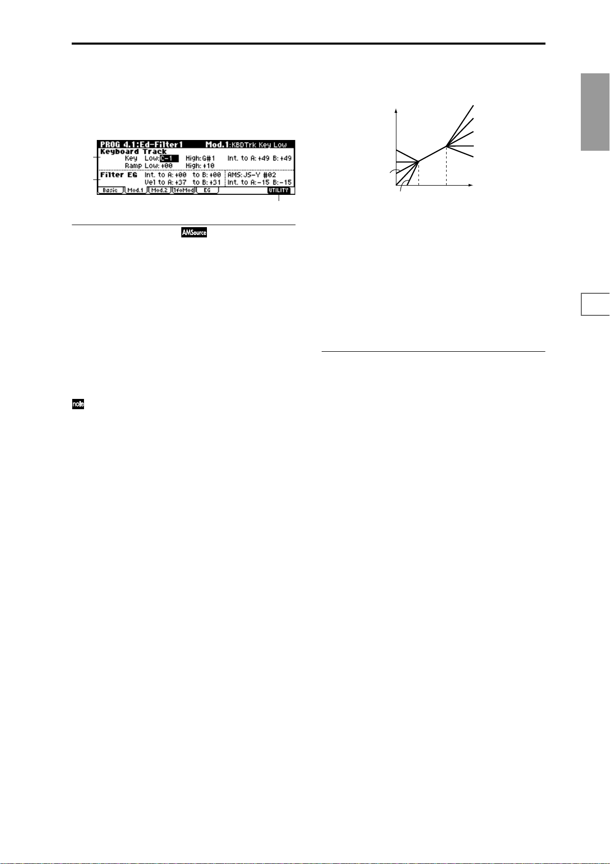
4.1–2: Mod.1 (Filter1 Modulation1)
Indicates settings for keyboard tracking which modifies the
tone by modulating the filter 1 cutoff frequency “Frequency
(A/B Frequency),” and intensity settings for the filter 1 EG,
etc.
4.1–2a
4.1–2b
4.1–2c
4.1–2a: Keyboard Track
These settings specify keyboard tracking for the cutoff frequency of filter 1. The way in which the cutoff frequency is
affected by the keyboard location you play can be specified
by the Key: “Low” and “High,” Ramp: “Low” and “High”
parameters.
Key:
Specifies the note numbers at which keyboard tracking will
begin to apply, and set the “Int. to A” and “(Int. to) B”
parameters to specify the depth and direction of the change
applied to filter 1 A and B.
For the range of notes between “Low (KBDTrk Key Low)”
and “High (KBDTrk Key High),” the cutoff frequency will
change according to the keyboard location (pitch).
You can also input the note number by holding down
the [ENTER] key and playing a note on a connected
MIDI device.
Low (KBDTrk Key Low) [C–1…G9]
Keyboard tracking will apply to the range below the specified note number.
High (KBDTrk Key High) [C–1…G9]
Keyboard tracking will apply to the range above the specified note number.
Ramp (Ramp Setting):
Specifies the angle of keyboard tracking.
Low (KBDTrk Ramp Low) [–99…+99]
High (KBDTrk Ramp High) [–99…+99]
If “Int. to A (KBDTrk Int. to A)” and “Int. to B (KBDTrk Int.
to B)” are set to +50, “Low (KBDTrk Ramp Low)” is set to
–62 and “High (KBDT rk Ramp High)” is set to +62, the angle
of the change in cutoff frequency will correspond to the keyboard location (pitch). This means that the oscillation that
occurs when you increase the “Resonance (A Resonance)”
(4.1–1b) will correspond to the keyboard location.
If you set “Low (KBDTrk Ramp Low)” to +43 and “High
(KBDTrk Ramp High)” to –43, the cutoff frequency will not
be affected by keyboard location. Use this setting when you
do not want the cutoff frequency to change for each note.
How cutoff frequency is affected by keyboard location and the Ramp
setting
(“Int. to A,” “Int. to B”=+50)
Cutoff frequency
Low Ramp=+99
Low Ramp=+43
Low Ramp=0
Low Ramp=–62
Low Ramp=–99
Low Key
High Key
High Ramp=+99
High Ramp=+62
High Ramp=0
High Ramp=–43
High Ramp=–99
Key
Int. to A (KBDTrk Int. to A) [–99...+99]
Specifies the depth and direction of the effect on filter 1A
produced by keyboard tracking settings “Low (KBDTrk Key
Low),” “High (KBDTrk Key High),” “Low (KBDTrk Ramp
Low),” and “High (KBDTrk Ramp High).”
With positive (+) settings, the ef fect will be in the same dir ec-
tion as the keyboard tracking settings. With negative (–) settings, the effect will be in the opposite direction.
Int. to B (KBDTrk Int. to B) [–99...+99]
Specifies the depth and direction of the effect on filter 1B
produced by keyboard tracking. (
☞“Int. to A”)
4.1–2b: Filter EG
Int. to A (Intensity to A) [–99…+99]
Specifies the depth and direction of the effect that the timevarying changes created by the filter 1 EG will have on the
filter 1A cutoff frequency.
With positive (+) settings, the sound will become brighter
when the EG levels set by Filter 1 EG “L (Level)” and “T
(Time)” parameters (4.1–5a) are in the “+” area, and darker
when they are in the “–” area.
With negative (–) settings, the sound will become darker
when the EG levels set by Filter 1 EG “L (Level)” and “T
(Time)” parameters are in the “+” area, and brighter when
they are in the “–” area.
Int. to B (Intensity to B) [–99…+99]
Specifies the depth and direction of the effect that the timevarying changes created by the filter 1 EG will have on the
filter 1B cutoff frequency.
☞(“Int. to A” Intensity to A)
Vel to A (Velocity to A) [–99…+99]
This parameter specifies the depth and direction of the effect
that velocity will have on the time-varying changes created
by the filter 1 EG (as set by “Filter 1 EG” 4.1–5) to control the
filter 1A cutoff frequency.
With positive (+) values, playing more strongly will cause
the filter 1 EG to produce greater changes in cutoff frequency . W ith negative (–) values, playing mor e strongly will
also cause the filter 1 EG to produce greater changes in cutoff frequency, but with the polarity of the EG inverted.
Vel to B (Velocity to B) [–99…+99]
This parameter specifies the depth and direction of the effect
that velocity will have on the time-varying changes created
by the filter 1 EG to control the filter 1B cutoff frequency.
☞(“Vel to A” Velocity to A).
PROG
1.1
2.12.22.33.14.14.25.15.25.36.17.17.27.3
15
Page 23
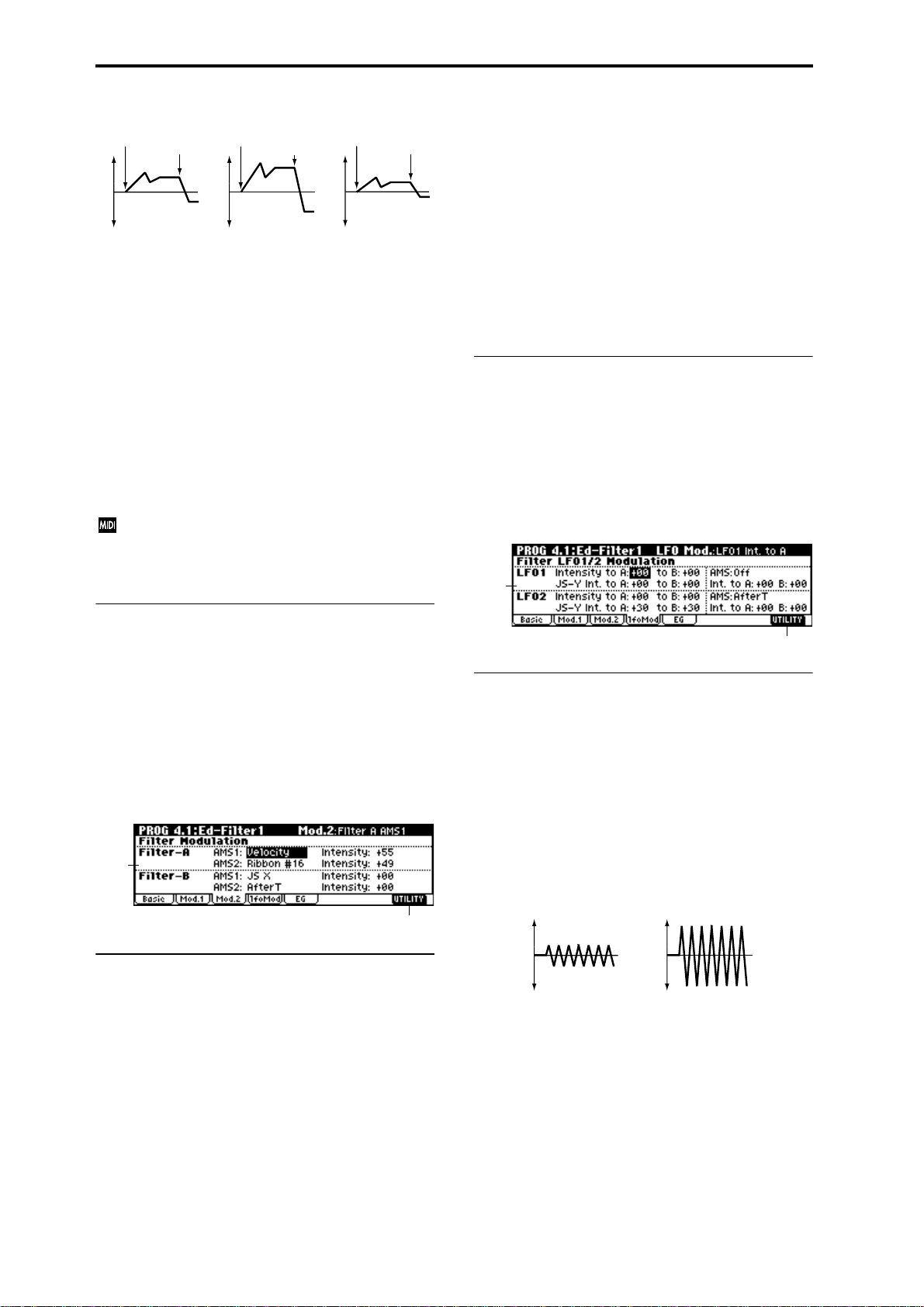
Changes in cutoff frequency
Note-on
Softly played
(The setting of Intensity to A (4.1–2b))
Note-off
Note-on
Strongly played
Setting to +
Note-off
Note-on
Strongly played
Setting to –
Note-off
AMS (Filter EG AMS) [Off, (EXT)]
Selects the source that will control the depth and direction of
the effect that the time-varying changes produced by the filter 1 EG will have on the cutoff frequency of filters 1A and
1B (
☞p.206 “AMS List”).
Int. to A (AMS Int. to A) [–99…+99]
Specifies the depth and direction of the effect that “AMS
(Filter EG AMS)” will have on filter 1A. For details on how
this will apply, refer to “Int. to A (Intensity to A).”
Int. to B (AMS Int. to B) [–99…+99]
Specifies the depth and direction of the effect that “AMS
(Filter EG AMS)” will have on filter 1B. For details on how
this will apply, refer to “Int. to A (Intensity to A).”
The sum of the settings for “Int. to A (B),” “Vel to A
(B),” and “Int. to A (B) (AMS Int. to A/B)” will determine the depth and direction of the effect produced by
the filter EG.
This value is added to the setting of the Filter A “Frequency
(A Frequency)”(4.1–1b).
AMS2 (Filter A AMS2) [Off, (PEG, AEG, EXT)]
Intensity (A AMS2 Intensity) [–99…+99]
Selects “AMS2 (Filter A AMS2),” and specify the depth and
direction of the effect that the selected source will have
(
☞“AMS1,” “Intensity”).
Filter–B:
This will be displayed when “Type (Filter Type)” (4.1–1a) is
Low Pass & High Pass.
Two alternate modulation sources can be used to modulate
the cutoff frequency of filter 1B (
■ 4.1–3b: UTILITY
☞“Write Program” (1.1–1d), “Copy Oscillator,” “Swap
☞“Filter A”).
Oscillator” (2.1–1d)
4.1–4: lfoMod (LFO Modulation)
Here you can use the filter 1 LFO to apply cyclic modulation
to the cutoff frequency of filter 1 (for oscillator 1) to create
cyclical changes in tone.
4.1–4a
■ 4.1–2c: UTILITY
☞“Write Program” (1.1–1d), “Copy Oscillator,” “Swap
Oscillator” (2.1–1d)
4.1–3: Mod.2 (Filter1 Modulation2)
Indicates settings for the controller that will modify the tone
by applying modulation to the filter 1 cutoff frequency “Frequency (A/B Frequency).”
If “Type (Filter Type)” (4.1–1a) is Low Pass Resonance, the
filter B parameters will not be displayed.
4.1–3a
4.1–3b
4.1–3a: Filter Modulation
Filter–A:
AMS1 (Filter A AMS1) [Off, (PEG, AEG, EXT)]
Selects the source that will control modulation of the filter
1A cutoff frequency (
Intensity (A AMS1 Intensity) [–99…+99]
Specifies the depth and direction of the effect that “AMS1
(Filter A AMS1)” will have.
When “AMS1 (Filter A AMS1)” is JS X, a positive (+) value
for this parameter will cause the cutoff frequency to rise
when the joystick is moved toward the right, and fall when
the joystick is moved toward the left. With a negative (–)
value for this parameter, the opposite will occur.
☞p.206 “AMS List”).
4.1–4b
4.1–4a: Filter LFO1/2 Modulation
LFO1
Intensity to A (LFO1 Int. to A) [–99…+99]
Specifies the depth and direction of the modulation that
OSC1 LFO1 (set by “OSC1 LFO1” 5.3–1a) will have on the
cutoff frequency of filter 1A.
Negative (–) settings will invert the phase.
Intensity to B (LFO1 Int. to B) [–99…+99]
Specifies the depth and direction of the modulation that
OSC1 LFO1 will have on the cutoff frequency of filter 1B
(
☞“Intensity to A”).
Change in cutoff
Low setting High setting
JS–Y Int. to A (LFO1 JS–Y Int. to A) [–99…+99]
By receiving CC#2 (or by moving the joystick in the –Y
direction on a TRITON or other instrument connected to
MIDI IN), you can control OSC1 LFO1 to modulate the cutoff frequency of filter 1A.
Specify the depth and direction of the effect.
For example, as this value is raised, OSC1 LFO1 will have a
correspondingly greater effect on filter 1 when the joystick is
moved in the –Y direction.
16
Page 24
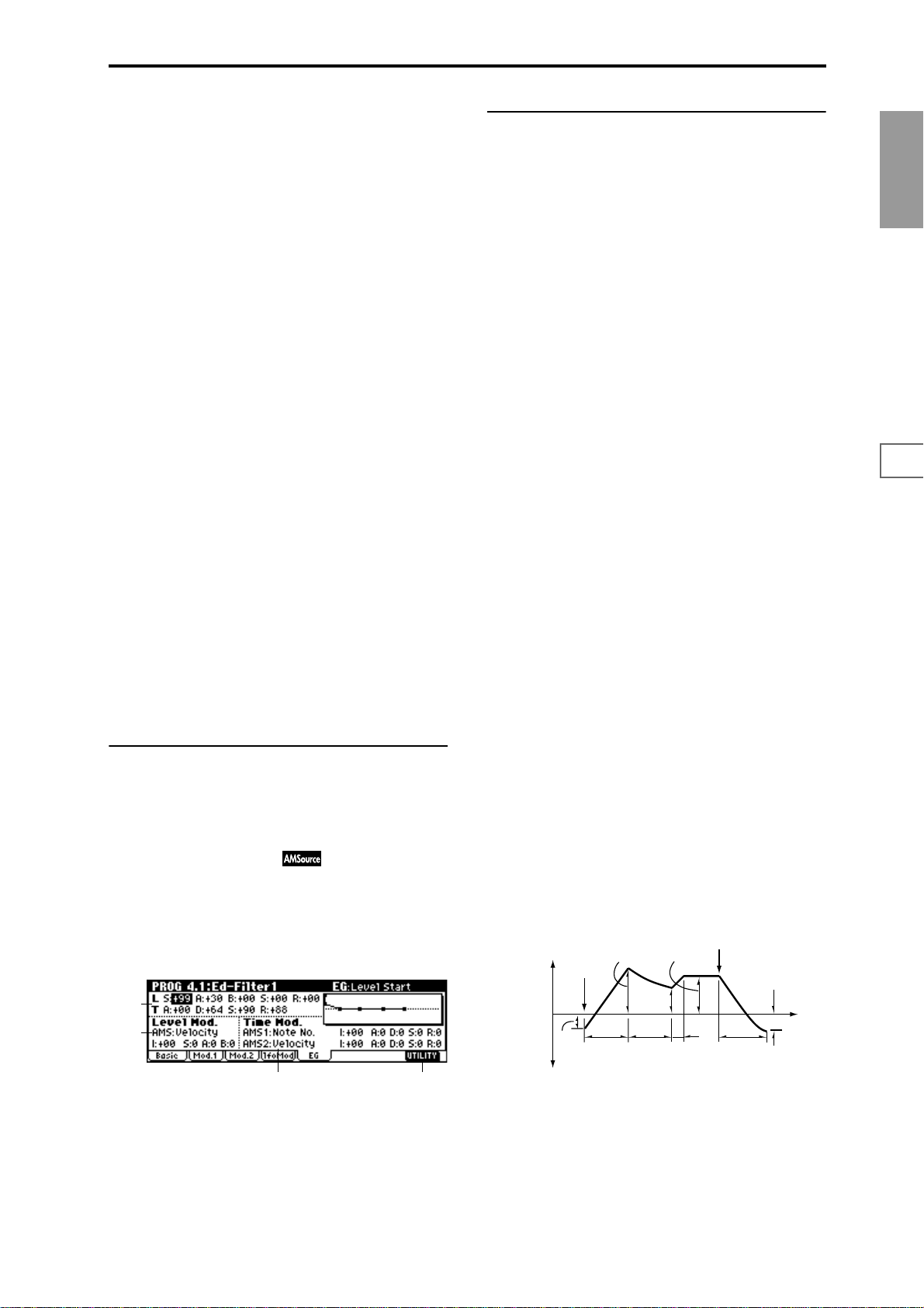
JS–Y Int. to B (LFO1 JS–Y Int. to B) [–99…+99]
By receiving CC#2 (or by moving the joystick in the –Y
direction on a TRITON or other instrument connected to
MIDI IN), you can control OSC1 LFO1 to modulate the cutoff frequency of filter 1B.
Specify the depth and direction of the effect. (
☞“JS –Y Int. to
A”)
AMS (LFO1 AMS) [Off, (PEG, FEG, AEG, KT, EXT)]
Selects a source that will control the depth and direction of
cutoff frequency change for both filters 1A and 1B (
☞p.206
“AMS List”).
Int. to A (LFO1 AMS Int. to A) [–99…+99]
Specifies the depth and direction of the effect that “AMS”
will have on filter 1A.
For example, if “AMS” is AfterT, higher settings of this
parameter will allow greater change to be applied to OSC1
LFO1 when you apply pressure to the keyboard of a connected MIDI instrument.
Int. to B (LFO1 AMS Int. to B) [–99…+99]
Specifies the depth and direction of the effect that “AMS”
will have on filter 1B (
☞“Int. to A”).
LFO 2
Adjusts the depth of the cyclic modulation applied by OSC1
LFO2 (set by “OSC1 LFO 2” 5.3–2) to the cutoff frequency of
filters 1A and 1B (
☞“LFO 1” 4.1–4a).
Intensity to A (LFO2 Int. to A) [–99…+99]
Intensity to B (LFO2 Int. to B) [–99…+99]
JS–Y Int. to A (LFO2 JS–Y Int. to A) [–99…+99]
JS–Y Int. to B (LFO2 JS–Y Int. to B) [–99…+99]
AMS (LFO2 AMS) [Off, (PEG, FEG, AEG, KT, EXT)]
Int. to A (LFO2 AMS Int. to A) [–99…+99]
Int. to B (LFO2 AMS Int. to B) [–99…+99]
■ 4.1–4b: UTILITY
☞“Write Program” (1.1–1d), “Copy Oscillator,” “Swap
Oscillator” (2.1–1d)
4.1–5: EG (Filter1 EG)
Here you can make settings for the EG that will produce
time-varying changes in the cutoff frequency of filters 1A
and 1B.
The depth of the effect that these settings will have on the
filter 1 cutoff frequency is determined by “Filter EG” (4.1–
2b).
4.1–5a
4.1–5b
4.1–5d4.1–5c
4.1–5a: Filter1 EG
Specifies the time-varying change produced by the filter 1
EG.
L (Level):
The result will depend on the filter that was selected in
“Type (Filter Type)” (4.1–1a). For example with the Low
Pass Resonance filter, positive (+) values of “Int. to A” (4.1–
2b) will cause the tone to be brightened by positive (+) lev-
els, and darkened by negative (–) levels.
S (Start Level) [–99…+99]
Specifies the change in cutoff frequency at the time of noteon.
A (Attack Level) [–99…+99]
Specifies the change in cutoff frequency after the attack time
has elapsed.
B (Break Point Level) [–99…+99]
Specifies the change in cutoff frequency after the decay time
has elapsed.
S (Sustain Level) [–99…+99]
Specifies the change in cutoff frequency that will be maintained from after the slope time has elapsed until note-off
occurs.
R (Release Level) [–99…+99]
Specifies the change in cutoff frequency that will occur when
the release time has elapsed.
T (Time):
These parameters specify the time over which each change
will occur.
A (Attack Time) [00…99]
Specifies the time over which the level will change from
note-on until the attack level is reached.
D (Decay Time) [00…99]
Specifies the time over which the level will change from the
attack level to the break point level.
S (Slope Time) [00…99]
Specifies the time over which the level will change after the
decay time has elapsed until the sustain level is reached.
R (Release Time) [00…99]
Specifies the time over which the level will change after
note-on occurs until the release level is reached.
Note-off
Break
Point
Level
Decay
Time
Sustain Level
Slope
Time
Release
Time
Release
Level
Time
The specified
cutoff
frequency
Start
Level
Note-on
Attack Level
Attack
Time
PROG
1.1
2.12.22.33.14.14.25.15.25.36.17.17.27.3
17
Page 25
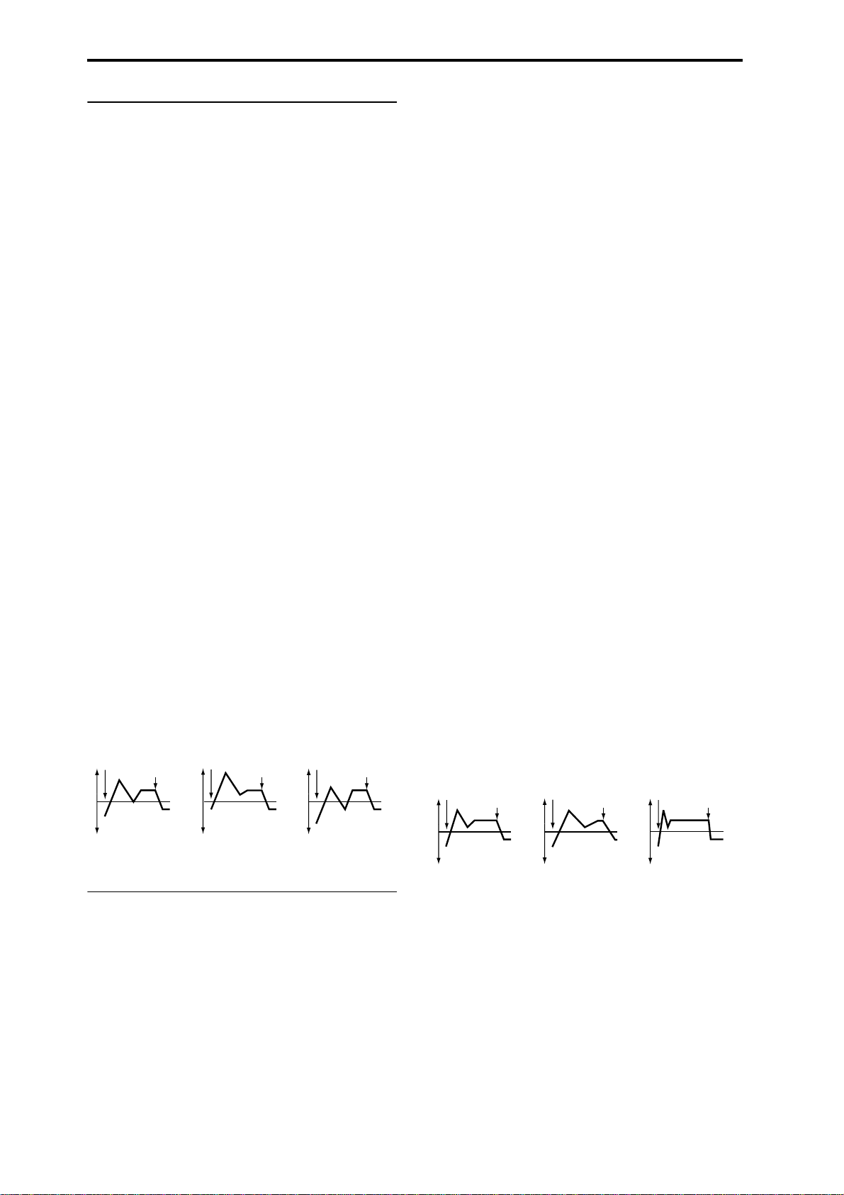
4.1–5b: Level Mod. (Level Modulation)
These settings let you use alternate modulation to control
the “L (Level)” parameters of the filter 1 EG.
AMS (Level Mod. AMS) [Off, (KT, EXT)]
Selects the source that will control the “L (Level)” parameters of the filter 1 EG (
☞p.206 “AMS List”).
I (AMS Intensity) [–99…+99]
Specifies the depth and direction of the effect that “AMS
(Level Mod. AMS)” will have.
For example, if “AMS (Level Mod. AMS)” is Velocity, and
you set “S (AMS SW Start),” “A (AMS SW Attack)” and “B
(AMS SW Break)” to + and set “I (AMS Intensity)” to a posi-
tive (+) value, the EG levels will rise as you play more
strongly. If “Intensity” is set to a negative (–) values, the EG
levels will fall as you play more strongly.
With a setting of 0, the levels specified by “Filter 1 EG” (4.1–
5a) will be used.
S (AMS SW Start) [–, 0, +]
Specifies the direction in which “AMS (Level Mod. AMS)”
will affect “S (Start Level).” When “I (AMS Intensity)” has a
positive (+) value, a setting of + for this parameter will
allow “AMS” to raise the EG level, and a setting of – will
allow “AMS” to lower the EG level. With a setting of 0 there
will be no change.
A (AMS SW Attack) [–, 0, +]
Specifies the direction in which “AMS (Level Mod. AMS)”
will affect “A(Attack Level).” When “I (AMS Intensity)” has
a positive (+) value, a setting of + for this parameter will
allow “AMS” to raise the EG level, and a setting of – will
allow “AMS” to lower the EG level. With a setting of 0 there
will be no change.
B (AMS SW Break) [–, 0, +]
Specifies the direction in which “AMS (Level Mod. AMS)”
will affect “B (Break Point Level).” When “I (AMS Intensity)” has a positive (+) value, a setting of + for this parameter will allow “AMS” to raise the EG level, and a setting of –
will allow “AMS” to lower the EG level. With a setting of 0
there will be no change.
Filter 1 EG changes (level) (AMS = Velocity, Intensity = a positive (+) value)
Note-on
Note-off
Note-on
Note-off
Note-on
Note-off
this parameter, positive (+) values of “Ramp (Ramp Setting)” (4.1–2a) will lengthen the EG times, and negative (–)
values of “Ramp (Ramp Setting)” will shorten the EG times.
The direction of change is specified by “A (AMS1 SW
Attack),” “D (AMS1 SW Decay),” “S (AMS1 SW Slope),” and
“R (AMS1 SW Release).”
With a setting of 0, the times specified by “Filter1 EG” (4.1–
5a) will be used.
If “AMS1 (Time Mod. AMS1)” is set to Velocity, positive (+)
values of this parameter will cause EG times to lengthen as
you play more strongly, and negative (–) values will cause
EG times to shorten as you play more strongly.
With a setting of 0, the times specified by “Filter1 EG” will
be used.
A (AMS1 SW Attack) [–, 0, +]
Specifies the direction in which “AMS1 (Time Mod. AMS1)”
will affect the attack time. With positive (+) values of “I
(AMS1 Intensity),” setting this parameter to + will allow
AMS1 to lengthen the time, and setting this parameter to –
will allow AMS1 to shorten the time. With a setting of 0
there will be no change.
D (AMS1 SW Decay) [–, 0, +]
Specifies the direction in which “AMS1 (Time Mod. AMS1)”
will affect the decay time. With positive (+) values of “I
(AMS1 Intensity),” setting this parameter to + will allow
AMS1 to lengthen the time, and setting this parameter to –
will allow AMS1 to shorten the time. With a setting of 0
there will be no change.
S (AMS1 SW Slope) [–, 0, +]
Specifies the direction in which “AMS1 (Time Mod. AMS1)”
will affect the slope time. With positive (+) values of “I
(AMS1 Intensity),” setting this parameter to + will allow
AMS1 to lengthen the time, and setting this parameter to –
will allow AMS1 to shorten the time. With a setting of 0
there will be no change.
R (AMS1 SW Release) [–, 0, +]
Specifies the direction in which “AMS1 (Time Mod. AMS1)”
will affect the release time. With positive (+) values of “I
(AMS1 Intensity),” setting this parameter to + will allow
AMS1 to lengthen the time, and setting this parameter to –
will allow AMS1 to shorten the time. With a setting of 0
there will be no change.
Filter 1 EG changes (Time) (AMS = Velocity, Intensity = a positive (+) value)
Note-on
Note-off
Note-on
Note-off
Note-on
Note-off
Softly played note with “S,”
“A,” and “B” set to + (setting
of 4.1–5a: Filter 1 EG)
Strongly played note with
“S,” “A,” and “B” set to +
Strongly played note with
“S,” “A,” and “B” set to –
4.1–5c: Time Mod. (Time Modulation)
These settings let you use alternate modulation to control
the “T (Time)” parameters of the filter 1 EG.
AMS1 (Time Mod. AMS1) [Off, (KT, EXT)]
Selects the source that will control the “T (Time)” parameters of the filter 1 EG (
☞p.206 “AMS List”).
I (AMS1 Intensity) [–99…+99]
Specifies the depth and direction of the effect that “AMS1
(Time Mod. AMS1)” will have.
For example, if “AMS1 (Time Mod. AMS1)” is set to Flt KTr
+/+, the EG “T (Time)” parameters will be controlled by the
Keyboard T rack (4.1–2a) settings. W ith positive (+) values of
18
Softly played note with “A,”
“D,” “S” and “R” set to +
(setting of 4.1–5a: Filter 1 EG)
Strongly played note with
“A,” “D,” “S” and “R” set to +
Strongly played note with
“A,” “D,” “S” and “R” set to –
AMS2 (Time Mod. AMS2) [Off, (EXT, KT)]
I (AMS2 Intensity) [–99…+99]
A (AMS2 SW Attack) [–, 0, +]
D (AMS2 SW Decay) [–, 0, +]
S (AMS2 SW Slope) [–, 0, +]
R (AMS2 SW Release) [–, 0, +]
These parameters are the settings for “AMS2” to control the
“Time” parameters of the filter 1 EG (
☞“AMS1”–“R”).
Page 26
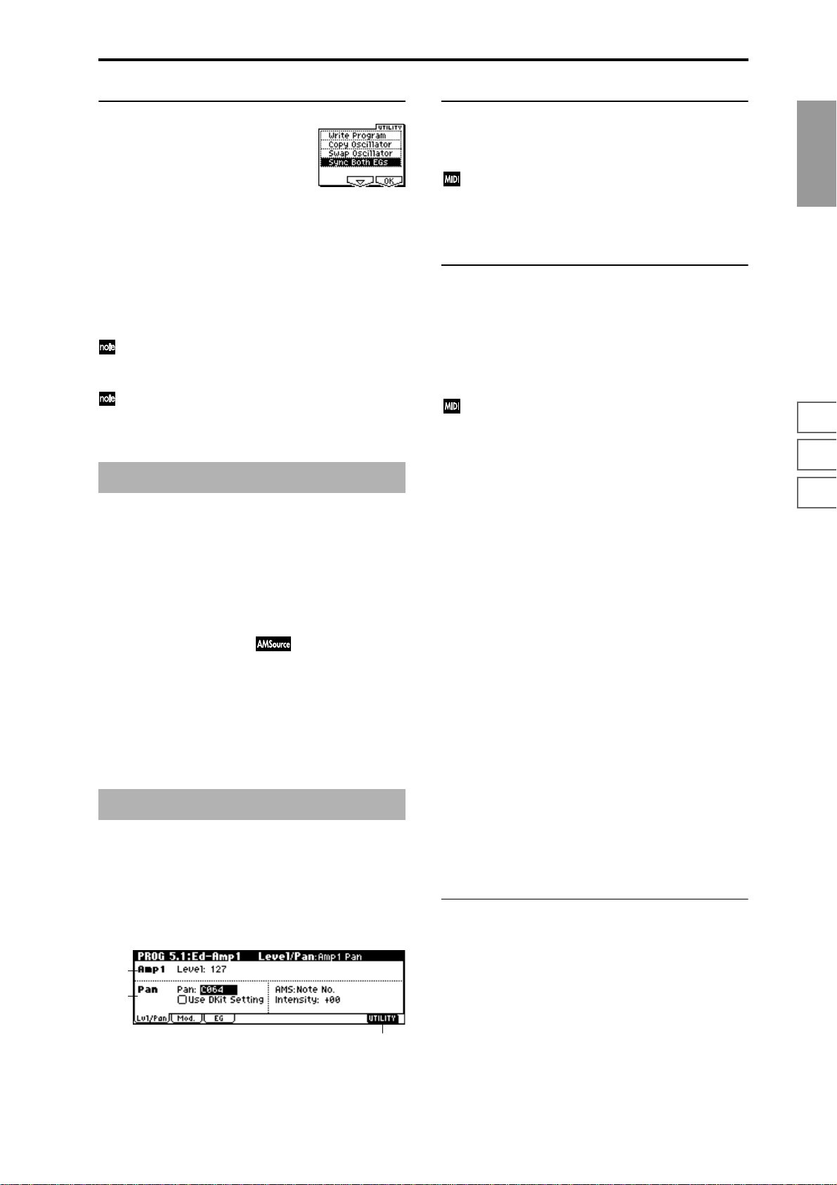
■ 4.1–5d: UTILITY
☞“Write Program” (1.1–1d), “Copy Oscillator,” “Swap
Oscillator” (2.1–1d)
Sync Both EGs
If you select “Sync Both EGs” from the Utility menu and
press the [F8] key, a check mark will appear at the left of
“Sync Both EGs.” In this state, the filter 1 EG and the filter 2
EG can be edited simultaneously. (Editing either one will
cause the other to change.)
“Sync Both EGs” cannot sync the filter EG and amp EG
independently . For example if you sync in 5.1–3d, it will
be synced here as well.
This can be selected only if “Mode (Oscillator Mode)”
(2.1–1a) is Double.
PROG 4.2: Ed–Filter2
4.2–1: Basic
4.2–2: Mod.1
(Filter2 Modulation1)
4.2–3: Mod.2 (Filter2 Modulation2)
4.2–4: lfoMod (LFO Modulation)
4.2–5: EG (Filter2 EG)
Indicates settings for filter 2, which controls the tone of oscillator 2. You can select either a 24 dB/oct low pass filter with
resonance, or a 12 dB/oct low pass filter and 12 dB/oct high
pass filter connected in series. Filter 2 can be used when
“Mode (Oscillator Mode)” (2.1–1a) is Double. (
Ed-Filter 1")
☞“PROG 4.1:
PROG 5.1: Ed–Amp1
Indicates settings for amp 1 which controls the volume of
oscillator 1. Pan settings are also made here.
5.1–1a: Amp1 Level
Level (Amp1 Level) [0…127]
Sets the volume of oscillator 1.
The volume of a program can be controlled by CC#7
(volume) and CC#11 (expression). The r esulting level is
determined by multiplying the values of CC#7 and
CC#11. The Global MIDI channel “MIDI Channel”
(GLOBAL 2.1–1a) is used for control.
5.1–1b: Pan
Pan (Amp1 Pan) [Random, L001…C064…R127]
Sets the pan (stereo location) of oscillator 1.
A setting of L001 places the sound at far left, C064 in the
center, and R127 to far right.
Random: The sound will be heard from a different location
at each note-on.
This can be controlled by CC#10 (panpot). A CC#10
value of 0 or 1 will place the sound at the far left, a
value of 64 will place the sound at the location specified
by the “Pan” setting for each oscillator, and a value of
127 will place the sound at the far right. This is controlled on the global MIDI channel “MIDI Channel”
(GLOBAL 2.1–1a).
Use DKit Setting [Off, On]
This is valid when “Mode (Oscillator Mode)” (2.1–1a) is set
to Drums.
On (Checked): The sound will be output at the “Pan” setting
that has been made for each key of the drum kit (GLOBAL
5.1–3a). When “Mode (Oscillator Mode)” is Drums, you will
normally use this setting.
Off (Unchecked): All notes will be output as specified by the
“Pan (Amp1 Pan)” setting.
AMS (Pan AMS) [Off, (PEG, FEG, AEG, LFO, KT, EXT)]
Selects the source that will modify pan (☞p.206 “AMS
List”). This change will be relative to the “Pan (Amp1 Pan)”
setting.
Intensity [–99…+99]
Specifies the depth of the effect produced by “AMS (Pan
AMS).”
For example, if “Pan (Amp1 Pan)” is set to C064 and “AMS
(Pan AMS)” is Note Number, positive (+) values of this
parameter will cause the sound to move toward the right as
the note numbers increase beyond the C4 note (i.e., as you
play higher), and toward the left as the note numbers
decrease (i.e., as you play lower). Negative (–) values of this
parameter will have the opposite effect.
PROG
1.1
2.12.22.33.14.14.25.15.25.36.17.17.27.3
5.1–1: Lvl/Pan (Level/Pan)
These parameters control the volume and pan of oscillator 1.
5.1–1a
5.1–1b
5.1–1c
■ 5.1–1c: UTILITY
☞“Write Program” (1.1–1d), “Copy Oscillator,” “Swap
Oscillator” (2.1–1d)
19
Page 27
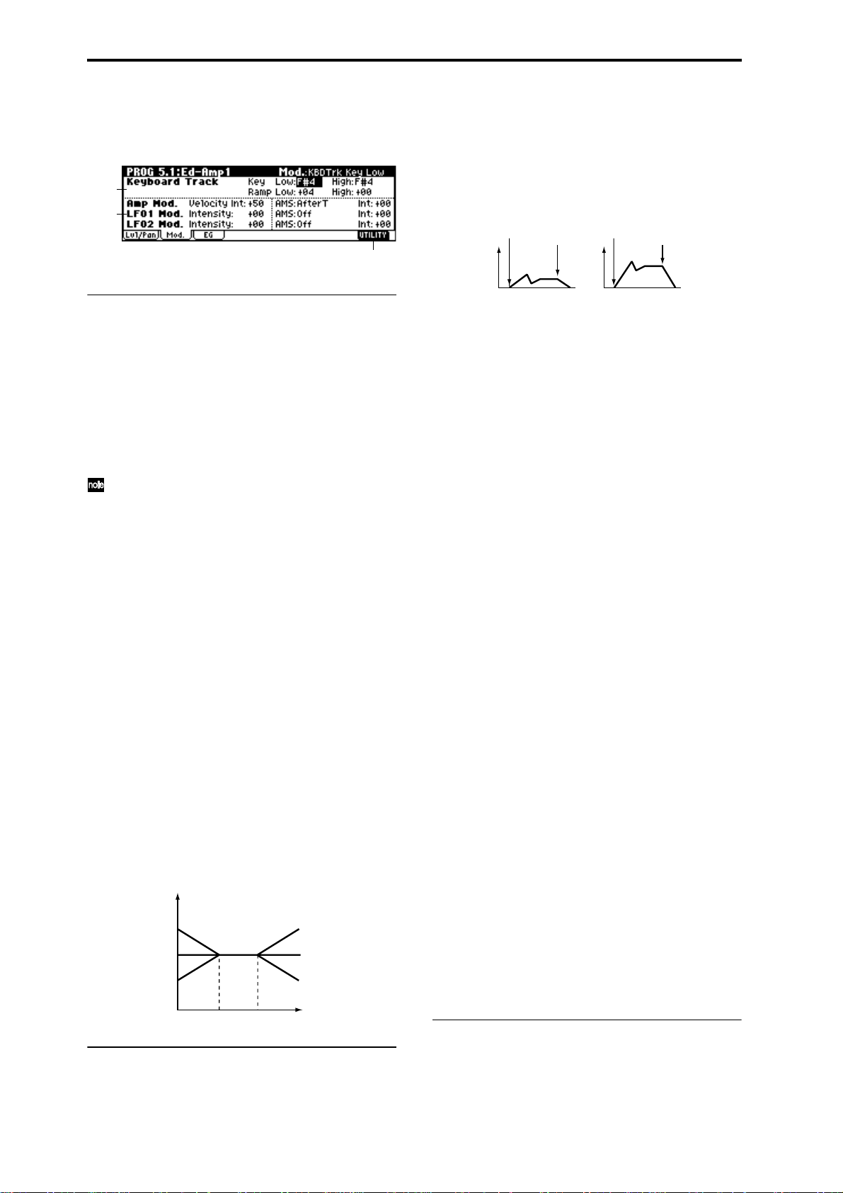
5.1–2: Mod. (Amp1 Modulation)
These settings allow you to apply modulation to amp 1 (for
oscillator 1) to modulate the volume.
5.1–2a
5.1–2b
5.1–2c
Amp Mod. (Amp Modulation)
Velocity Int. (Amp Velocity Int.) [–99…+99]
With positive (+) values, the volume will increase as you
play more strongly.
With negative (–) values, the volume will decrease as you
play more strongly.
Volume change (with positive (+) values of this parameter)
Note-on
Note-off
Note-on
Note-off
5.1–2a: Keyboard Track
These parameters let you use keyboard tracking to adjust
the volume of oscillator 1. Use the “Key” and “Ramp”
parameters to specify how the volume will be affected by
the keyboard location that you play.
Key (Keyboard Track Key):
Specifies the note number at which keyboard tracking will
begin to apply.
The volume will not change between “Low (KBDTrk Key
Low)” and “High (KBDTrk Key High).”
You can also input the note number by holding down
the [ENTER] key and playing a note on a connected
MIDI device.
Low (KBDTrk Key Low) [C–1…G9]
Keyboard tracking will apply to the range of notes below the
note number you specify here.
High (KBDTrk Key High) [C–1…G9]
Keyboard tracking will apply to the range of notes above the
note number you specify here.
Ramp (Ramp Setting):
Specifies the angle of the keyboard tracking.
Low (KBDTrk Ramp Low) [–99…+99]
With positive (+) values of this parameter, the volume will
increase as you play notes below the “Low (KBDTrk Key
Low)” note number. With negative (–) values, the volume
will decrease.
High (KBDTrk Ramp High) [–99…+99]
With positive (+) values of this parameter, the volume will
increase as you play notes above the “High (KBDTrk Key
High)” note number. With negative (–) values, the volume
will decrease.
Volume change produced by keyboard location and Ramp settings
Volume
Ramp Low=+99
Ramp Low=0
Ramp Low=–99
KBDTrk Low KBDTrk High
Ramp High=+99
Ramp High=0
Ramp High=–99
Key
Softly played
Strongly played
AMS (Amp AMS) [Off, (PEG, FEG, EXT)]
Selects the source that will control the volume of amp 1
(
☞p.206 “AMS List”) (EXT) Velocity cannot be selected.
Int. (AMS Intensity) [–99…+99]
Specifies the depth and direction of the effect that “AMS
(Amp AMS)” will have.
The actual volume will be determined by multiplying the
value of the changes produced by the amp EG with the values of Alternate Modulation etc., and if the levels of the amp
EG are low, the modulation applied by Alternate Modulation will also be less.
For example, if you set “AMS (Amp AMS)” to AfterT and
press down on the keyboard of a connected MIDI instrument, the volume will increase if you have set this parameter to a positive (+) value. However if the volume is already
at maximum due to the EG settings etc., it will not be possible to increase the volume any further. If you have set this
parameter to a negative (–) value, pressing down on the
keyboard will decrease the volume.
LFO1 Mod. (LFO1 Modulation)
Intensity (LFO1 Intensity) [–99…+99]
These parameters let you use “OSC1 LFO1” (5.3–1) to control the oscillator 1 volume.
Negative (–) values will invert the LFO waveform.
AMS (LFO1 AMS) [Off, (PEG, FEG, AEG, KT, EXT)]
Selects a source that will control the depth by which “OSC1
LFO1” will modulate the volume of oscillator 1 (
☞p.206
“AMS List”).
Int. (AMS Intensity) [–99…+99]
Specifies the depth and direction of the effect that “OSC1
LFO1” will have on the volume of oscillator 1. Negative (–)
values will invert the LFO waveform.
LFO2 Mod. (LFO2 Modulation)
Intensity (LFO2 Intensity) [–99…+99]
AMS (LFO2 AMS) [Off, (PEG, FEG, AEG, KT, EXT)]
Int. (AMS Intensity) [–99…+99]
Specifies the depth and direction of the effect that “OSC1
LFO2”(5.3–2) will have on the volume of oscillator 1. Refer
to the preceding sections “LFO1 Mod. (LFO1 Modulation).”
■ 5.1–2c: UTILITY
5.1–2b: Amp Mod., LFO1 Mod., LFO2 Mod.
Indicates settings to specify how the volume of oscillator 1
will be controlled by velocity, OSC1 LFO1, and OSC1 LFO2.
20
☞“Write Program” (1.1–1d), “Copy Oscillator,” “Swap
Oscillator” (2.1–1d)
Page 28
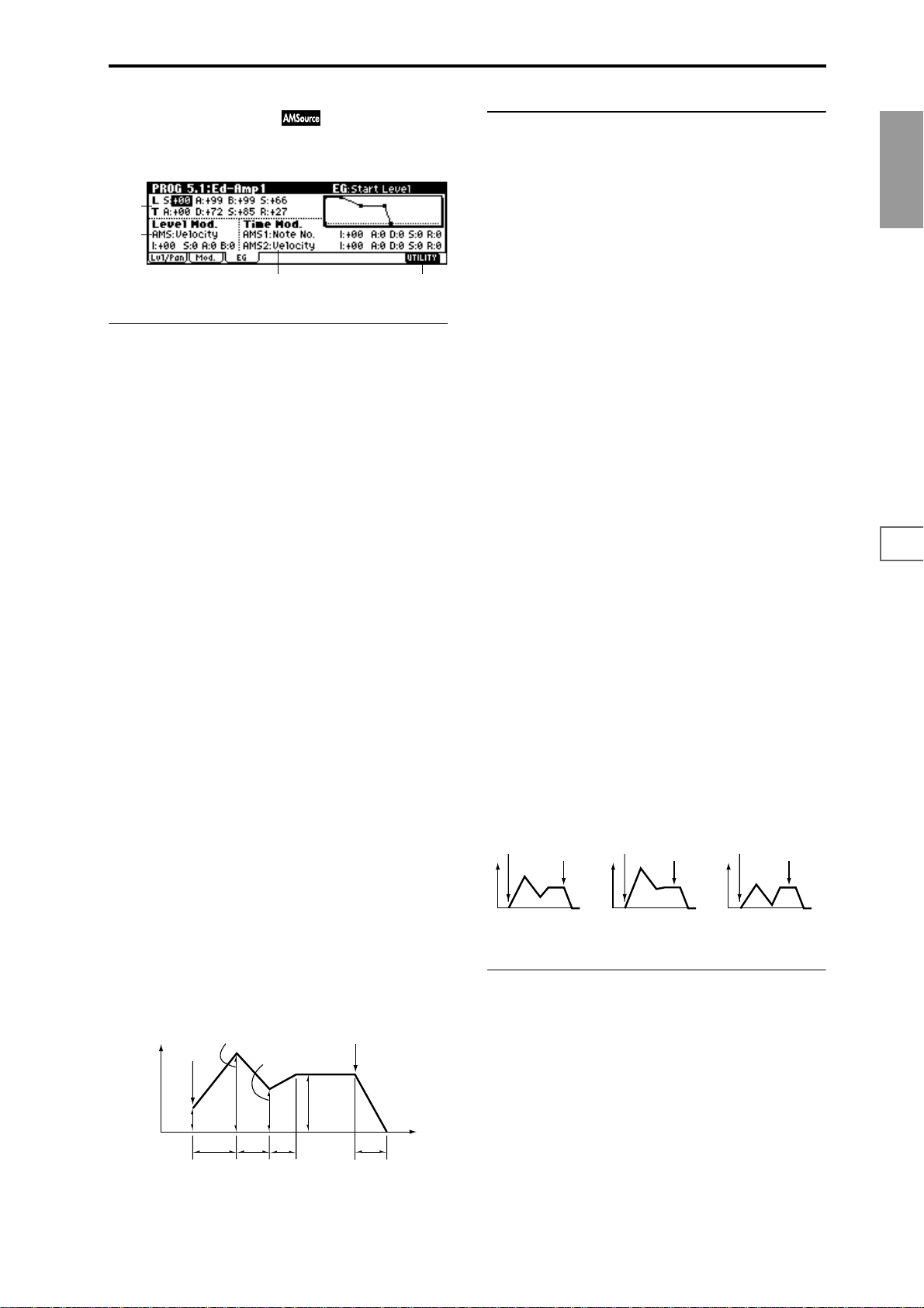
5.1–3: EG (Amp1 EG)
Indicates settings to specify how Amp 1 will cause the volume of oscillator 1 to change over time.
5.1–3a
5.1–3b
5.1–3d5.1–3c
5.1–3a: Amp1 EG
These parameters specify how the amp 1 EG will change
over time.
L (Level):
S (Start Level) [00…99]
Specifies the volume level at note-on.
If you want the note to begin at a loud level, set this to a high
value.
A (Attack Level) [00…99]
Specifies the volume level that will be reached after the
attack time has elapsed.
B (Break Point Level) [00…99]
Specifies the volume level that will be reached after the
decay time has elapsed.
S (Sustain Level) [00…99]
Specifies the volume level that will be maintained from after
the slope time has elapsed until note-off occurs.
Time:
A (Attack Time) [00…99]
Specifies the time over which the volume will change after
note-on until it reaches the attack level.
If the start level is 0, this will be the rise time of the sound.
D (Decay Time) [00…99]
Specifies the time over which the volume will change from
when it reaches the attack level until it reaches the break
point level.
5.1–3b: Level Mod. (Level Modulation)
These parameters let you use AMS to control the amp 1 EG
levels that were specified in “Amp 1 EG” (5.1–3a).
AMS (Level Mod. AMS) [Off, (KT, EXT)]
Selects the source that will control the “Level” parameters of
the amp 1 EG (
☞p.206 “AMS List”).
I (AMS Intensity) [–99…+99]
Specifies the depth and direction of the effect that “AMS
(Level Mod. AMS)” will have.
For example, if “AMS (Level Mod. AMS)” is Velocity, setting
“S (AMS SW Start),” “A (AMS SW Attack),” and “B (AMS
SW Break)” to + and setting “Intensity” to a positive (+)
value will cause the amp 1 EG volume levels to increase as
you play more strongly. Setting “Intensity” to a negative (–)
values will cause the amp 1 EG volume levels to decrease as
you play more strongly. With a setting of 0, the levels will be
as specified in “Amp 1 EG” (5.1–3a).
S (AMS SW Start) [–, 0, +]
Specifies the direction in which “AMS (Level Mod. AMS)”
will change “S (Start Level).” If “I (AMS Intensity)” is set to
a positive (+) value, setting this parameter to + will allow
AMS to increase the EG level, and setting this parameter to –
will allow AMS to decrease the EG level. With a setting of 0,
no change will occur.
A (AMS SW Attack) [–, 0, +]
Specifies the direction in which “AMS (Level Mod. AMS)”
will change “A (Attack Level).” If “I (AMS Intensity)” is set
to a positive (+) value, setting this parameter to + will allow
AMS to increase the EG level, and setting this parameter to –
will allow AMS to decrease the EG level. With a setting of 0,
no change will occur.
B (AMS SW Break) [–, 0, +]
Specifies the direction in which “AMS (Level Mod. AMS)”
will change “B (Break Point Level).” If “I (AMS Intensity)” is
set to a positive (+) value, setting this parameter to + will
allow AMS to increase the EG level, and setting this parameter to – will allow AMS to decrease the EG level. With a setting of 0, no change will occur.
Amp 1 EG changes (Level) (AMS=Velocity, Intensity = a positive (+) value)
Note-on
Note-off
Note-on
Note-off
Note-on
Note-off
PROG
1.1
2.12.22.33.14.14.25.15.25.36.17.17.27.3
S (Slope Time) [00…99]
Specifies the time over which the volume will change from
when it reaches the break point level until it reaches the sustain level.
R (Release Time) [00…99]
Specifies the time over which the volume will change after
note-off until it reaches 0.
Volume
Amplifier EG
Note-on
Attack Level
Start
Level
Attack
Time
Break Point
Decay
Time
Slope
Time
Sustain
Level
Note-off
Time
Release Time
Softly played note when “S”=0
and “A” and “B” are set to +
(settings of 5.1–3a: Amp 1 EG)
Strongly played note
when “S”=0 and “A” and
“B” are set to +
Strongly played note
when “S”=0 and “A” and
“B”are set to –
5.1–3c: Time Mod. (Time Modulation)
Y ou can use two AMS sources to contr ol the Amp 1 EG times
that were specified in “Amp 1 EG” (5.1–3a).
AMS1 (Time Mod. AMS1) [Off, (EXT, KT)]
Selects the source that will control the “Time” parameters of
Amp 1 EG. (
☞p.206 “AMS List”)
I (AMS1 Intensity) [–99…+99]
Specifies the depth and direction of the effect that “AMS1
(Time Mod. AMS1)” will have.
For example, if “AMS1 (Time Mod. AMS1)” is Amp KT +/+,
the (Amp) “Keyboard Track” settings (5.1–2a) will control
the EG “Time” parameters. With positive (+) values of this
21
Page 29
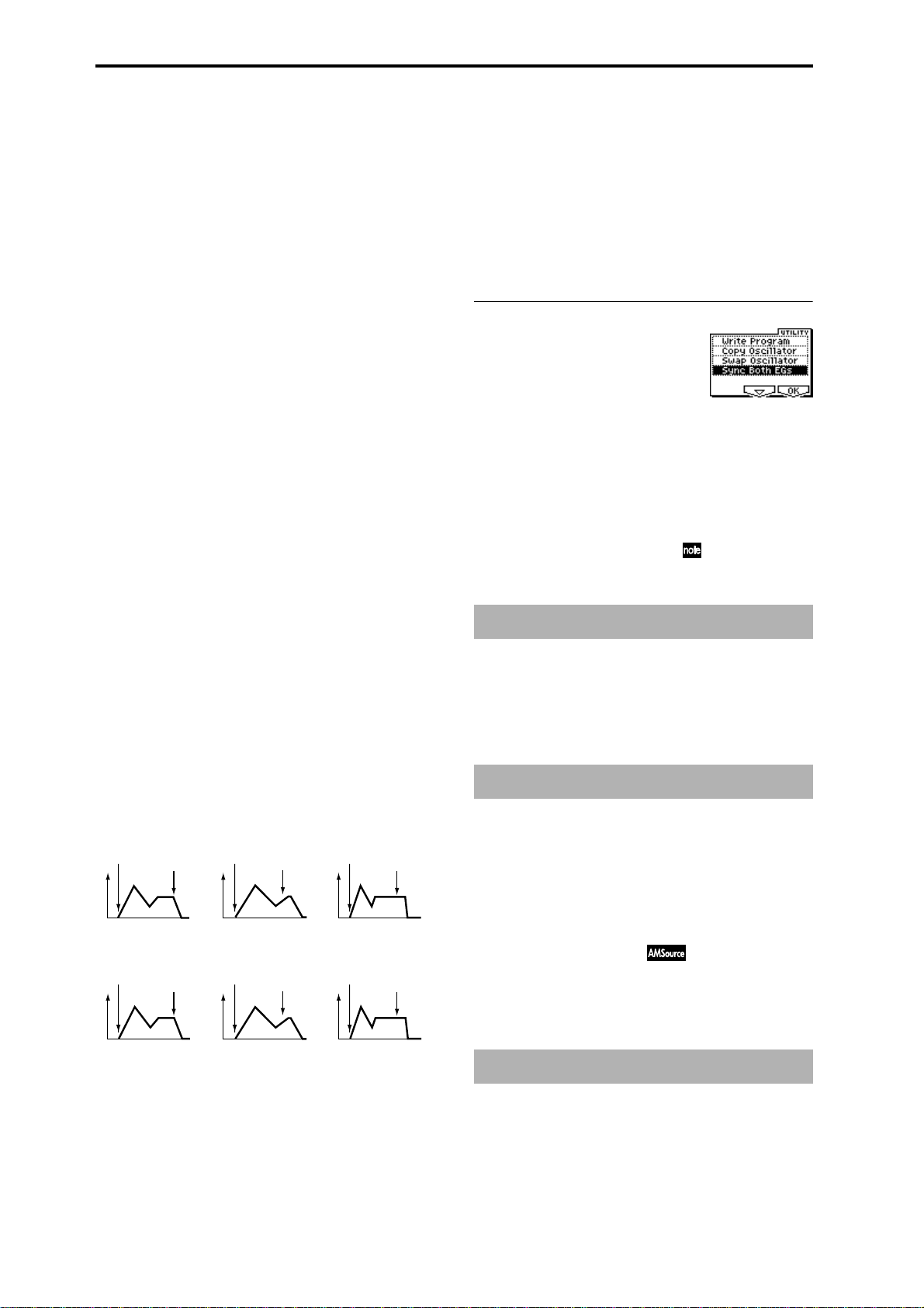
parameter, positive (+) values of “Ramp (Ramp Setting)”
will cause EG times to be lengthened, and negative (–) val-
ues of “Ramp (Ramp Setting)” will cause EG times to be
shortened. The direction of the change is specified by “A
(AMS1 SW Attack),” “D (AMS1 SW Decay),” “S (AMS1 SW
Slope),” and “R (AMS1 SW Release).”
When “AMS1 (Time Mod. AMS1)” is Velocity, positive (+)
values will cause EG times to lengthen as you play more
strongly, and negative (–) values will cause EG times to
shorten as you play more strongly. With a setting of 0, the EG
times will be as specified in “Amp1 EG” (5.1–3a).
AMS2 (Time Mod. AMS2) [Off, (EXT, KT)]
I (AMS2 Intensity) [–99…+99]
A (AMS2 SW Attack) [–, 0, +]
D (AMS2 SW Decay) [–, 0, +]
S (AMS2 SW Slope) [–, 0, +]
R (AMS2 SW Release) [–, 0, +]
These parameters specify how “AMS2 (Time Mod. AMS2)”
will control the amp 1 EG “Time” parameters (
(Time Mod. AMS1)”–“R(AMS1 SW Release)”).
☞“AMS1
A (AMS1 SW Attack) [–, 0, +]
Specifies the direction of the effect that “AMS1 (Time Mod.
AMS1)” will have on “A (Attack Time).” With positive (+)
values of “I (AMS1 Intensity),” setting this parameter to +
will allow AMS1 to lengthen the time, and setting it to – will
allow AMS1 to shorten the time. With a setting of 0 there
will be no effect.
D (AMS1 SW Decay) [–, 0, +]
Specifies the direction of the effect that “AMS1 (Time Mod.
AMS1)” will have on “D (Decay Time).” With positive (+)
values of “I (AMS1 Intensity),” setting this parameter to +
will allow AMS1 to lengthen the time, and setting it to – will
allow AMS1 to shorten the time. With a setting of 0 there
will be no effect.
S (AMS1 SW Slope) [–, 0, +]
Specifies the direction of the effect that “AMS1 (Time Mod.
AMS1)” will have on “S (Slope Time).” With positive (+)
values of “I (AMS1 Intensity),” setting this parameter to +
will allow AMS1 to lengthen the time, and setting it to – will
allow AMS1 to shorten the time. With a setting of 0 there
will be no effect.
R (AMS1 SW Release) [–, 0, +]
Specifies the direction of the effect that “AMS1 (Time Mod.
AMS1)” will have on “R (Release Time).” With positive (+)
values of “I (AMS1 Intensity),” setting this parameter to +
will allow AMS1 to lengthen the time, and setting it to – will
allow AMS1 to shorten the time. With a setting of 0 there
will be no effect.
Amp 1 EG changes (Time)
(AMS=Amp KTrk +/+, Intensity = a positive (+) value)
(When Amp Keyboard Track (5.1–2a) Low Ramp= a positive (+) value, and
High Ramp = a positive (+) value)
Note-on
Note-off
Note-on
Note-off
Note-on
Note-off
■ 5.1–3d: UTILITY
☞“Write Program” (1.1–1d), “Copy Oscillator,” “Swap
Oscillator” (2.1–1d)
Sync Both EGs
If you select “Sync Both EGs” from the Utility menu and
press the [F8] key, a check mark will appear at the left of
“Sync Both EGs.” In this state, the amp 1 EG and the amp 2
EG can be edited simultaneously. (Editing either one will
cause the other to change.) (
☞4.1–5d )
PROG 5.1: Ed–Amp
This page is displayed if the separately sold EXB-MOSS
option is installed.
☞EXB-MOSS owner’s manual & p.251 “EXB-MOSS
(
option”)
PROG 5.2: Ed–Amp2
Indicates settings for amp 2 which controls the volume of
oscillator 2. Pan settings are also made here.
Settings of 5.1–3a: Amp 1
EG
Amp 1 EG changes (Time) (AMS=Velocity, Intensity= a positive (+) value)
Note-on
Softly played note with “A,”
“D,” “S” and “R” at + (settings
of 5.1–3a: Amp 1 EG)
Note-off
Low-pitched note played
with “A,” “D,” “S”, and “R”
at +
Note-on
Strongly played note with
“A,” “D,” “S” and “R” at +
Note-off
22
High-pitched note played
with “A,” “D,” “S”, and “R”
at –
Note-on
Strongly played note with
“A,” “D,” “S” and “R” at –
Note-off
5.2–1: Lvl/Pan (Level/Pan)
5.2–2: Mod. (Amp2 Modulation)
5.2–3: EG (Amp2 EG)
These will appear when “Mode (Oscillator Mode)” (2.1–1a)
is Double. (
☞“5.1: Ed–Amp1”)
PROG 5.2: Ed–EGs
This page is displayed if the separately sold EXB-MOSS
option is installed.
☞EXB-MOSS owner’s manual & p.251 “EXB-MOSS
(
option”)
Page 30
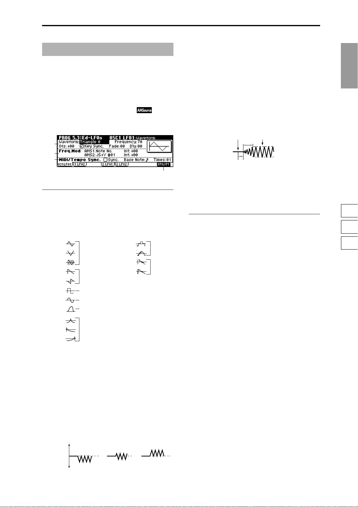
PROG 5.3: Ed–LFOs
Here you can make settings for the LFO that can be used to
cyclically modulate the Pitch, Filter, and Amp of oscillators 1
and 2. There are two LFO units for each oscillator. By setting
the LFO1 or LFO2 Intensity to a negative (–) value for Pitch,
Filter, or Amp, you can invert the LFO waveform.
Key Sync. [Off, On]
On (Checked): Key Sync. will be On. The LFO will start each
time you play a note, and an independent LFO will operate
for each note.
Off (Unchecked): Key Sync. will be Off, and the LFO effect
that was started by the first-played note will continue to be
applied to each newly-played note. (In this case, Delay and
Fade will be applied only to the LFO when it is first started.)
PROG
5.3–1: OS1LFO1 (OSC1 LFO1)
Indicates settings for the “OSC1 LFO1,” which is the first
LFO that can be used for oscillator 1.
5.3–1a
5.3–1b
5.3–1c
5.3–1d
5.3–1a: OSC1 LFO1
Waveform [Triangle 0…Random6 (Vect.)]
Selects the LFO waveform.
The numbers that appear at the right of some of the LFO
waveforms indicate the phase at which the waveform will
begin.
Triangle 0
Triangle 90
Triangle
Random
Saw 0
Saw 180
Square
Sine
Guitar
Exp.Triangle
Exp.Saw Down
Exp.Saw Up
Triangle wave
Phase will change
randomly at each key-in
Sawtooth down↓
Square wave
Sine wave
Guitar vibrato
Frequency [00…99]
Sets the LFO frequency. A setting of 99 is the fastest.
Ofs (Offset) [–99…+99]
Specifies the central value of the LFO waveform.
For example, with a setting of 0 as shown in the following
diagram, the vibrato that is applied will be centered on the
note-on pitch. With a setting of +99, the vibrato will only
raise the pitch above the note-on pitch, in the way in which
vibrato is applied on a guitar.
When “Waveform” is set to Guitar, the modulation will
occur only in the positive (+) direction even if you set “Offset” to 0.
Offset settings and pitch change produced by vibrato
offset = –99 offset = 0 offset = +99Pitch
Step Triangle – 4
Step Triangle – 6
Step Saw – 4
Step Saw – 6
Random1 (S/H):
Conventional sample & hold (S/H) in which the
level changes randomly at fixed intervals of
time
Random2 (S/H):
Both the levels and the time intervals will
change randomly.
Random3 (S/H):
The maximum level and minimum level will
alternate at random intervals of time (i.e., a
square wave with random period).
Random4 (Vect.)
Random5 (Vect.)
Random6 (Vect.)
These types cause Random 1–3 to change
smoothly. They can be used to simulate the
instability of acoustic instruments etc.
Fade [00…99]
Specifies the time from when the LFO begins to apply until
it reaches the maximum amplitude. When “Key Sync.” is
Off, the fade will apply only when the LFO is first started.
How “Fade” affects the LFO (when “Key Sync.” is On)
Note-on Note-off
Fade
Delay
Dly (Delay) [0…99]
Specifies the time from note-on until the LFO effect begins to
apply.
When “Key Sync.” is Off, the delay will apply only when
the LFO is first started.
5.3–1b: Freq.Mod (Frequency Modulation)
You can use two alternate modulation sources to adjust the
speed of the OSC1 LFO1.
AMS1 (Freq. AMS1)
[Off, (PEG, FEG, AEG, LFO2, KT, EXT)]
Selects the source that will adjust the frequency of the oscillator 1 LFO1 (
☞p.206 “AMS List”). OSC1 LFO1 can be mod-
ulated by OSC1 LFO2.
Int (AMS1 Intensity) [–99…+99]
Specifies the depth and direction of the effect that “AMS1
(Freq. AMS1)” will have.
When this parameter is set to a value of 16, 33, 49, 66, 82, or
99, the LFO frequency being can be increased by a maximum of 2, 4, 8, 16, 32, or 64 times respectively (or decreased
by 1/2, 1/4, 1/8, 1/16, 1/32, or 1/64 respectively).
For example, if “AMS1 (Freq. AMS1)” is Note No., positive
(+) values of this parameter will cause the oscillator 1 LFO
to speed up as you play higher notes. Negative (–) values
will cause the oscillator 1 LFO to slow down as you play
higher notes. This change will be centered on the C4 note.
If “AMS1 (Freq. AMS1)” is JS+Y #01, higher values of this
setting will cause the OSC1 LFO speed to become corresponding faster when a joystick is operated on a TRITON
etc. connected to MIDI IN. With a setting of +99, moving the
joystick all the way away from yourself will increase the
LFO speed by approximately 64 times.
AMS2 (Freq. AMS2)
[Off, (PEG, FEG, AEG, LFO2, KT, EXT)]
Int (AMS2 Intensity) [–99…+99]
Indicates settings for a second alternate modulation source
that will adjust the frequency of the oscillator 1 LFO1.
☞“AMS1 (Freq. AMS1),” “Int. (AMS1 Intensity)”
1.1
2.12.22.33.14.14.25.15.25.36.17.17.27.3
Pitch at note-on
23
Page 31

5.3–1c: MIDI/Tempo Sync.
(Frequency MIDI/Tempo Sync.)
Sync. (MIDI/Tempo Sync.) [Off, On]
On (Checked): The LFO frequency will synchronize to the
tempo (MIDI Clock). In this case, the values you specified
for “Frequency” (5.3–1a) and “Freq.Mod” (5.3–1b) will be
ignored.
Base Note (Sync. Base Note)
[ , , , , , , , ]
Times (Sync. Times) [01...16]
When “Sync. (MIDI/Tempo Sync.).” is checked, these When
“Sync. (MIDI/Tempo Sync.)” is checked, these parameters
specify a note length “Base Note (Sync. Base Note)” relative
to “ (Tempo)” and the multiple “Times (Sync. Times)” that
will be applied to it. These parameters will determine the
frequency of the OSC1 LFO1. For example if “Base Note
(Sync. Base Note)” is (quarter note) and “Times (Sync.
Times)” is 04, the LFO will perform one cycle every four
beats.
Even if you change the “ (Tempo)” setting of the arpeggiator, the LFO will always perform one cycle every four beats.
■ 5.3–1d: UTILITY
☞“Write Program” (1.1–1d)
For details on how to select the desired utility function, refer
to “PROG 1.1–1d: UTILITY.”
Swap LFO 1&2
This exchanges the settings of LFO 1 and 2. If LFO2 is
selected in AMS1 (Freq. AMS1) or AMS2 (Freq. AMS2) of
LFO1 Freq.Mod (5.3–1b), the settings will be invalid for
LFO2 after LFO1 and 2 have been exchanged. If you select
this from the OSC1 LFO1 or OSC1 LFO2 page, LFO1 and
LFO2 of OSC1 will be exchanged.
1 Select “Swap LFO 1&2” to access the dialog box.
2 To execute, press the [F8] (“OK”) key. To cancel without
executing, press the [F7] (“Cancel”) key.
5.3–4: OS2LFO2 (OSC2 LFO2)
This can be used when “Mode (Oscillator Mode)” (2.1–1a) is
set to Double. Here you can make settings for the OSC2
LFO2, which is the second LFO that can be applied to oscillator 2 (
☞“5.3–1: OS1LFO1 (OSC1 LFO1)” and “5.3–2:
OS1LFO2 (OSC1 LFO2)”).
PROG 6.1: Ed–Arp. (Arpeggiator)
Here you can make settings for the arpeggiator used by the
program.
These arpeggiator settings can be linked when you switch
programs. To link, check the Program item in “Auto Arp.
“Program” (GLOBAL 1.1–1c): On.
The arpeggiator can be switched on/off by the [ARP ON/
OFF] key. When on, the key LED will light.
The settings of the REALTIME CONTROLS C-mode
[TEMPO] knob, [ARP-GATE] knob, [ARP-VELOCITY]
knob, and [ARP ON/OFF] key can be saved for each program.
These settings will be valid when Auto Arp. “Program”
is On.
You can control the arpeggiator from an external
sequencer, or record arpeggio note data on an external
sequencer. (
“Pattern,” “Resolution,” “Octave,” “Sort,” “Latch,”
“Key Sync.,” “Keyboard,” and “ (Tempo)” can also be
set in the Arp. Play page of 1.1:Play.
6.1–1: Setup (Arpeg. Setup)
6.1–1a
6.1–1a: Arpeggiator Setup
☞p.228)
6.1–1b
5.3–2: OS1LFO2 (OSC1 LFO2)
Here you can make settings for the OSC1 LFO2, which is the
second LFO that can be applied to oscillator 1. (
OS1LFO1 (OSC1 LFO1)”) However, it is not possible to use
the LFO to apply modulation in “AMS1 (Freq. AMS1)” or
“AMS2 (Freq. AMS2)” of Freq. Mod.
☞“5.3–1:
5.3–3: OS2LFO1 (OSC2 LFO1)
This can be used when “Mode (Oscillator Mode)” (2.1–1a) is
set to Double. Here you can make settings for the OSC2
LFO1, which is the first LFO that can be applied to oscillator
2 (
☞“5.3–1: OS1LFO1 (OSC1 LFO1)”).
24
☞Refer to BG p.85.
Pattern* [P000...P004, U000(I-A/B)...U327(E–H)]
Selects the arpeggio pattern.
P000: UP Preset Arpeggio Pattern
P001: DOWN Preset Arpeggio Pattern
P002: ALT1 Preset Arpeggio Pattern
P003: ALT2 Preset Arpeggio Pattern
P004: RANDOM Preset Arpeggio Pattern
U000(I–A/B)...U199(I–A/B) (for Preloaded User Arpeggio Pattern)
U200(E–A)...U215(E–A), U216(E–B)...U231(E–B), U232(E–
C)...U247(E–C), U248(E–D)...U263(E–D), U264(E–E)...U279(E–E),
U280(E–F)...U295(E–F), U296(E–G)...U311(E–G), U312(E–
H)...U327(E–H)
(for EXB-PCM series, User Arpeggio Pattern)
P000–P004 are preset arpeggio patterns, U000 (I–A/B)–
U327(E–H) are user arpeggio patterns. User arpeggio pat-
terns can be created in GLOBAL 6.1.
Page 32

Arpeggio patterns U000 (I–A/B)–U327(E–H) can be
selected using the numeric keys [0]–[9] and the
[ENTER] key.
Octave* [1, 2, 3, 4]
Specifies the number of octaves in which the arpeggio will
be played.
If a user arpeggio pattern is selected, the range of the
arpeggio will depend on the “Octave Motion” (GLOBAL 6.1–1c) setting.
Reso (Resolution)* [ , , , , , ]
Specifies the timing resolution of the arpeggio. The notes of
the arpeggio will be played at the interval you specify: ,
, , , , or . The speed of the arpeggio pattern is
determined by the “ (Tempo)” and the “Resolution.”
Gate [000...100(%), Step]
Specifies the length (gate time) of each note in the arpeggio.
000–100(%): Each note will be played with the specified gate
time.
Step: This is available when an user arpeggio pattern U000
(I-A/B)–U327 (E-H) is selected for “Pattern.” When this is
selected, the gate time specified for each step will be used.
The gate time can also be controlled by the [ARP-GATE]
knob. Rotating the knob toward the left will shorten the gate
time, and rotating it toward the right will lengthen the gate
time. When the knob is at the 12 o’clock position, the gate
time will be as specified here.
Velocity [001...127, Key, Step]
Specifies the velocity of the notes in the arpeggio.
001–127: Each note will sound with the specified velocity
value.
Key: Each note will sound with the velocity value at which
it was actually played.
Step: This is available when an user arpeggio pattern U000
(I-A/B)–U327 (E-H) is selected for “Pattern.” When this is
selected, the velocity specified for each step will be used.
The velocity can also be controlled by the [ARP-VELOCITY]
knob. Rotating the knob toward the left will decrease the
velocity, and rotating it toward the right will increase the
velocity. When the knob is at the 12 o’clock position, the
velocity will be as specified here.
Latch*
Specifies whether or not the arpeggio will continue playing
after you take your hand off the keyboard of a connected
MIDI instrument.
On (Checked): The arpeggio will continue playing after you
remove your hand from the keyboard.
Off (Unchecked): The arpeggio will stop when you remove
your hand from the keyboard.
Key Sync.* [Off, On]
Specifies whether the arpeggio pattern will begin when you
press a key on a connected MIDI instrument, or whether it
will always follow the “ (Tempo)” setting.
On (Checked): The arpeggio pattern will start playing from
the beginning when a note-on occurs from a condition
where no keys are pressed. This setting is suitable when you
are playing in realtime and want the arpeggio to play from
the beginning of the measure.
Off (Unchecked): The arpeggio pattern will always play
according to the “ (Tempo) .”
Keyboard*
This specifies whether the notes you play on the keyboard of
a connected MIDI instrument will be sounded as usual in
addition to being sounded as part of the arpeggio.
On (Checked): The notes you play will be sounded on their
own, in addition to being sounded as part of the arpeggio.
For example if you simultaneously press two or more notes,
they will be sounded as usual in addition to being played as
arpeggiated notes.
Off (Unchecked): Only the arpeggiated notes will be heard.
* These parameters can also be set in “1.1–3: Arp.”
6.1–1b: Arpeggiator Tempo
(Tempo) [040...240, EXT]
Sets the tempo.
This can also be set by the [TEMPO] knob. When “MIDI
Clock” (GLOBAL 2.1–1a) is External, this will indicate EXT,
and the arpeggiator will synchronize to MIDI Clock messages received from an external MIDI device.
■ 6.1–1c: UTILITY
PROG
1.1
2.12.22.33.14.14.25.15.25.36.17.17.27.3
Swing [–100...+100(%)]
This parameter shifts the timing of the odd-numbered notes
of the arpeggio.
When Resolution =
Step
123456789
–50 –25 +25 +25
Swing
Sort* [Off, On]
This specifies the order in which the notes you press will be
arpeggiated.
On (Checked): Notes will be arpeggiated in the order of
their pitch, regardless of the order in which you pressed
them.
Off (Unchecked): Notes will be arpeggiated in the order in
which you pressed them.
☞“Write Program” (1.1–1d)
For details on how to select the desired utility function, refer
to “PROG 1.1–1d: UTILITY.”
Copy Arpeggiator
This command copies arpeggio settings.
1 Select “Copy Arpeggiator” to access the dialog box.
2 In “From” specify the copy source arpeggio settings
(mode, bank, number).
3 If you are copying from Combination or Multi mode,
specify whether you wish to copy from A or B.
4 To execute the Copy Arpeggio operation, press the [F8]
(“OK”) key. To cancel, press the [F7] (“Cancel”) key.
25
Page 33

6.1–2: Zone (Scan Zone)
6.1–2a
6.1–2b
PROG 7.1: Ed–BUS
These settings specify the bus on which the output of the
oscillator will be sent, and adjust the send levels to the master effects.
☞For details on insertion effects, refer to p.141 “8. Effect
Guide.”
6.1–2a: Scan Zone
Zone Map
This shows the “Scan Zone” setting.
Key:
Btm (Bottom Key) [C–1...G9]
Top (Top Key) [C–1...G9]
These parameters specify the range of notes (keys) for which
the arpeggiator will function. “Top” is the upper limit, and
“Btm” is the lower limit.
Vel:
Btm (Bottom Velocity) [001...127]
Top (Top Velocity) [001...127]
Specifies the range of velocities for which the arpeggiator
will function. “Top” is the upper limit, and “Btm” is the
lower limit.
The note number and velocity can also be specified by
holding down the [ENTER] key and pressing a note on
the keyboard of a connected MIDI device.
■ 6.1–2b: UTILITY
☞“Write Program” (1.1–1d), “Copy Arpeggiator” (6.1–1c)
7.1–1: BUS
The following diagram shows the LCD screen when “Mode
(Oscillator Mode)” (2.1–1a) is set to Single or Double.
7.1–1a
7.1–1a: BUS
BUS Select
BUS Select (All OSCs)
[L/R, IFX1...5, 1...4, 1/2, 3/4, Off]
Specifies the bus to which oscillators 1 and 2 will be sent.
If this is set to 1/2 or 3/4, the oscillator pan settings (5.1–
1b, 5.2–1) will be used to output the sound in stereo
from AUDIO OUTPUT (INDIVIDUAL) 1/2 or 3/4.
When the oscillator pan is controlled by CC#10 (pan) or
AMS (Alternate Modulation Source), the sound will be
output with the pan setting that is in effect at note-on.
Unlike the case when this is set to L/R to output the
sound from (MAIN) L/MONO and R, the pan of a
sounding note will not change in realtime.
If you wish to adjust the pan in realtime during a note
and output the sound from AUDIO OUTPUT (INDIVIDUAL) 1/2 or 3/4, set “BUS Select” to IFX1 (or IFX2–
IFX5), set “IFX1” (or IFX2–IFX5 (7.2–1a)) to 000: No
Effect, and set the “BUS Select” (7.2–1a) after passing
through IFX to 1/2 or 3/4.
26
MFX Send
OSC1 Send1 [000...127]
Sets the volume (send level) at which the output of OSC1
will be sent to master effect 1. This is valid when “BUS
Select” is set to L/R or Off.
If “BUS Select” is set to IFX1, IFX2, IFX3, IFX4 or IFX5, the
send levels to master effect 1 and 2 are set by “S1
(Send1(MFX1))” and “S2 (Send2(MFX2))” (7.2–1a) after
passing through IFX 1/2/3/4/5 of the InsertFX pages.
OSC1 Send2 [000...127]
Sets the volume (send level) at which the output of OSC1
will be sent to master effect 2 (
☞“OSC1 Send1”).
OSC2 Send1 [000...127]
OSC2 Send2 [000...127]
Sets the volume (send level) at which the output of OSC2
will be sent to master effects 1 and 2. These parameters will
be valid when “Mode (Oscillator Mode)” (2.1–1a) is set to
Double and “BUS Select” is set to L/R or Off.
Page 34
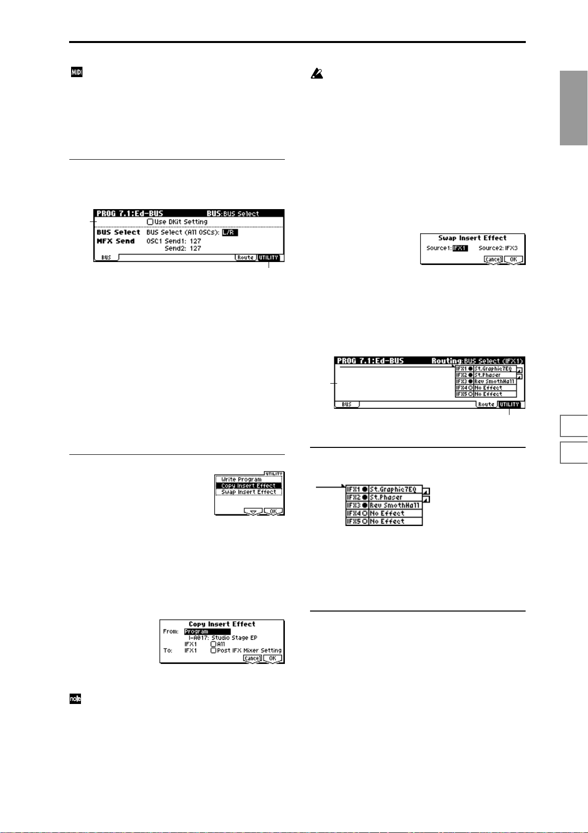
CC#93 will control the Send 1 level for OSC 1 and 2,
and control change #91 will control the Send 2 level for
OSC 1 and 2. These are controlled on the global MIDI
channel “MIDI Channel” (GLOBAL 2.1–1a).
The actual send level is determined by multiplying
these values with the send level setting of each oscillator.
7.1–1b: Use DKit Setting
The LCD screen shown below is for when “Mode (Oscillator
Mode)” (2.1–1a) is set to Drums.
7.1–1b
If you are copying from a master effect, the result may
not be identical, due to differences in the routing and
level settings of a master effect.
4 Select the copy destination insert effect. If you check
“Post IFX Mixer Setting,” the “Chain,” “Pan (CC#8),”
“BUS Select,” “S1 (Send1(MFX1))” and “S2
(Send2(MFX2))” settings that follow the copy source
insert effect will also be copied. If this is unchecked, only
the effect type and its parameters will be copied.
5 To execute the Copy Insert Effect command, press the
[F8] (“OK”) key. To cancel, press the [F7] (“Cancel”) key.
Swap Insert Effect
This command swaps (exchanges) insert effect settings.
1 Select “Swap Insert Effect” to access the dialog box.
PROG
1.1
2.12.22.33.14.14.25.15.25.36.17.17.27.3
7.1–1c
Use DKit Setting [Off, On]
This will be available when “Mode (Oscillator Mode)” is set
to Drums.
On (Checked): The “BUS (BUS Select)” (GLOBAL 5.1–3a)
setting for each key of the selected drum kit will be used.
Check this when you want to apply an insert effect to an
individual drum instrument, or to output an individual
drum instrument to one of the AUDIO OUTPUT (INDIVIDUAL) jacks.
If the “Mode (Oscillator Mode)” is Single or Double, this
setting has no effect.
Off (Unchecked): The setting of the “BUS Select,”“MFX
Send” (7.1–1c) parameter described below will be used. All
drum instruments will be sent to the specified bus.
■ 7.1–1c: UTILITY
☞“Write Program” (1.1–1d)
For details on how to select the desired utility function, refer
to “PROG 1.1–1d: UTILITY.”
Copy Insert Effect
This command copies effect settings from Program, Combination, Multi, or Sampling mode.
1 Select “Copy Insert Effect” to access the dialog box.
2 In “Source 1” and “Source 2,” select each of the insert
effects that you wish to swap.
3 To execute the Swap Insert Effect command, press the
[F8] (“OK”) key. To cancel, press the [F7] (“Cancel”) key.
7.1–2: Route (Routing)
7.1–2a
7.1–2b
7.1–2a: Routing
This displays the setting status of the insert effects.
This shows the insert effect routing, the names of the
selected effects, their on/off setting, and chain status. The
insert effect type, on/off, and chain settings can be made in
the Setup page of 7.2: Ed-InsertFx.
You can use the [INC], [DEC] keys and [VALUE] dial to set
“BUS Select” (
■ 7.1–2b: UTILITY
☞7.1–1a).
2 In “From” select the copy source mode, bank, and num-
ber.
You can use the [BANK] and [A]–[H] keys to select the
bank.
3 Select the effect that you wish to copy. You can also copy
from a master effect. If “All” is checked, all effect settings
will be copied (i.e., the contents of the InsertFX page and
the effect parameters of IFX 1–5, but not “Ctrl Ch”).
☞“Write Program” (1.1–1d), “Copy Insert Effect,” “Swap
Insert Effect” (7.1–1c)
27
Page 35

PROG 7.2: Ed–InsertFX
7.2–1: Setup
Here you can select the type of each insert effect, turn it on/
off, and make chain settings.
The direct sound (Dry) of an insert effect is always stereo
input and output. The input/output of the effect sound
(Wet) will depend on the effect type (
7.2–1a
☞p.142).
7.2–1b
BUS Select [L/R, 1, 2, 3, 4, 1/2, 3/4, Off]
Specifies the bus to which the sound will be sent after passing through the insert effect. Normally you will set this to L/
R. If you wish to output to AUDIO OUTPUT (INDIVIDUAL), set this to 1, 2, 3, 4, 1/2, or 3/4. The Off setting is used
when you wish to use “S1 (Send1(MFX1))” and “S2
(Send2(MFX2))” and in addition connect to the master
effects in series.
S1 (Send1 (MFX1)) [000...127]
S2 (Send2 (MFX2)) [000...127]
Sets the send levels to the master effects 1 and 2 for the
sound that has passed through the insert effect. These settings are valid when “BUS Select” (7.1–1a) has been set to L/
R or Off.
Control change CC#93 will control the Send 1 level, and
control change CC#91 will control the Send 2 level.
These messages are received on the global MIDI channel specified by “MIDI Channel” (GLOBAL 2.1–1a).
7.2–1a: InsertFX Setup
IFX1 On/Off — IFX5 On/Off [Off, ON]
Selects the insert effect on/off.
When this is Off, the input will be output without change.
(For 000: No Effect, on/off will produce the same result.)
Separately from this setting, you can use control change
#92 to turn off all insert effects together. A value of 0
will be off, and a value of 1–127 will be the original setting. This message is received on the global MIDI channel specified by “MIDI Channel” (GLOBAL 2.1–1a).
Insert Effect 1, 5 [000...089: name]
Insert Effect 2, 3, 4 [000...102: name]
Selects the type of each insert effect.
For “Insert Effect 1” and “Insert Effect 5” you can select fr om
90 types of effect: 000: No Effect – 089: Reverb-Gate. Double-size effects cannot be used.
For “Insert Effect 2,” “Insert Effect 3” and “Insert Effect 4”
you can select from 103 types of effect: 000: No Effect – 102:
Hold Delay.
If you select a double-size effect, the next insert effect will be
unavailable for use. For example if you select a double-size
effect for IFX2, IFX3 cannot be used. A maximum of two
double-size effects can be used (normal size for IFX1, double
size for IFX2 and IFX4) (
These effects can also be selected by category in Utility
“Select by Category” (7.2–1b).
☞p.142).
Chain [ (Off), (ON)]
Selects “chain” on/off for each insert effect.
For example if “Chain” for IFX1 is set to (ON), IFX1 and
IFX2 will be connected in series. If “BUS Select” (7.1–1a) is
set to IFX1, IFX1 and IFX2 will be inserted in series.
A maximum of five insert effects (IFX1–IFX5) can be inserted
in series. When effects are chained, the “Pan (CC#8),” “BUS
Select,” “S1 (Send1(MFX1))” and “S2 (Send2(MFX2))” settings that follow the last IFX in the chain will be used.
■ 7.2–1b: UTILITY
☞“Write Program” (1.1–1d), “Copy Insert Effect,” “Swap
Insert Effect” (7.1–1c)
Select by Category
Selects insert effects by category.
For the procedure, refer to “Select by Category” (
This command can be used when selecting “Insert
Effect 1”–”Insert Effect 5.”
☞p.2).
7.2–2: IFX 1
7.2–3: IFX 2
7.2–4: IFX 3
7.2–5: IFX 4
7.2–6: IFX 5
Here you can set the effect parameters for the IFX 1/2/3/4/
5 that were selected in the Setup page (
Effect dynamic modulation (Dmod) is controlled on the
global MIDI channel “MIDI Channel” (GLOBAL 2.1–
1a). (
☞p.211 “D.mod”)
☞p.151).
Pan(CC#8) (Post IFX Pan CC#8) [L000...C064...R127]
Sets the pan after the sound has passed through the insert
effect. This setting is valid only when the following “BUS
Select” is set to L/R (
CC#8 will control.
☞p.145).
28
7.2–2a
Page 36
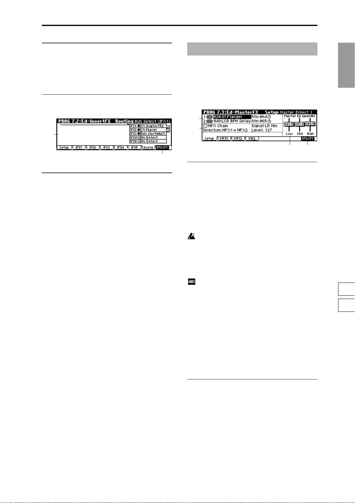
■ 7.2–2(...6)a: UTILITY
☞“Write Program” (1.1–1d)
7.2–7: Routing
7.2–7a: Routing
This shows the status of the insert effect settings. (☞7.1–2a)
7.2–7a
7.2–7b
PROG 7.3: Ed–MasterFX
☞For details on the master effects, refer to p.146.
7.3–1: Setup
Here you can select the master effect types, switch them on/
off, specify chaining, and set the master EQ.
7.3–1a
7.3–1b
7.3–1d7.3–1c
7.3–1a: Master Effect Setup
PROG
1.1
2.12.22.33.14.14.25.15.25.36.17.17.27.3
■ 7.2–1b: UTILITY
☞“Write Program” (1.1–1d), “Copy Insert Effect,” “Swap
Insert Effect” (7.1–1c)
The master effects do not output the direct sound (Dry). The
return level (“Rtn 1, 2”) sends the effect sound (Wet) to the L
and R bus, and this is mixed with the direct sound (“BUS
Select” L/R: 7.1–1a, 7.2–1a).
The master effects are monaural input. The sound that is
panned to L and R after passing through the oscillator and
insert effects is mixed to a monaural signal as adjusted by
the “S1 (Send1 (MFX1))” and “S2 (Send2 (MFX2))” levels,
and input to the master effects.
The master effects are mono-in stereo-out. Even when
a stereo-input type effect is selected, the input will be
monaural.
MFX1 On/Off, MFX2 On/Off [Off, ON]
Switch master effect 1, 2 on/off. When off, the output will be
muted.
Separately from this setting, you can use CC#94 to switch
master effect 1 on/off, CC#95 to switch master effect 2
on/off. A value of 0 will be off, and a value of 1–127 will
be the original setting. This is controlled on the global
MIDI channel “MIDI Channel” (GLOBAL 2.1–1a).
Master Effect 1, 2 [000...089: name]
Selects the effect type for master effect 1, 2. You can select
from 90 types of effect: 000: No Effect–089: Reverb-Gate.
(Double-size effects cannot be selected.) If 000: No Effect is
selected, the output from the master effect will be muted.
Rtn 1, 2 (Return 1, 2) [000...127]
Adjusts the return levels from the master effects to the L/R
bus (main output L/MONO, R).
7.3–1b: Chain
MFX Chain [Off, On]
On (Checked): Chain (series connection) will be turned on
for MFX1 and MFX2. (
☞p.148)
Direction (Chain Direction)
[MFX1→MFX2, MFX2→MFX1]
Specifies the direction of the connection when MFX1 and
MFX2 are chained.
MFX1→MFX2: Connect from MFX1 to MFX2.
MFX2→MFX1: Connect from MFX2 to MFX1.
29
Page 37

Signal (Chain Signal) [LR Mix, L Only, R Only]
When chain is On, this parameter specifies how the stereo
output signal of the first master effect will be connected to
the input (mono) of the next master effect.
L/R Mix: The stereo output L/R of the first master effect will
be mixed before being input to the next master effect.
L Only, R Only: Only the left or right channel of the output
will be input to the next master effect.
Level (Chain Level) [000...127]
Sets the send level from the first master effect to the next
master effect when chain is turned on.
7.3–1c: Master EQ Gain [dB]
Sets the gain for the three-band EQ located immediately
before the sound of the L/R bus is sent from the AUDIO
OUTPUT (MAIN OUT) L/MONO and R jacks. This is
linked with the various “Gain” parameters of Master EQ
(7.3–4).
Swap Master Effect
This command swaps (exchanges) the settings of MFX1 and
MFX2.
1 Select “Swap Master Effect” to access the dialog box.
2 To execute the Swap Master Effect command, press the
[F8] (“OK”) key. To cancel, press the [F7] (“Cancel”) key.
Select by Category
Selects master effects by category. (☞p.2)
This command can be used when selecting “Master
Effect 1”–”Master Effect 2.”
7.3–2: MFX 1
Low [–18.0...+18.0]
Mid [–18.0...+18.0]
High [–18.0...+18.0]
The cutoff frequency for “Low,” “Mid” and “High” and the
“Q” of “Mid” can be adjusted in the MEQ page. These set-
tings are in “dB” units.
■ 7.3–1d: UTILITY
☞“Write Program” (1.1–1d)
For details on how to select the desired utility function, refer
to “PROG 1.1–1d: UTILITY.”
Copy Master Effect
This command lets you copy any desired effect settings from
Program, Combination, Multi or Sampling modes.
1 Select “Copy Master Effect” to access the dialog box.
7.3–3: MFX 2
Indicates effect parameter settings for the MFX1 and 2
effects that were selected in the Setup page (
(
☞p.211 “D.mod”)
■ 7.3–2(3)a: UTILITY
☞“Write Program” (1.1–1d)
☞p.151).
7.3–2b
7.3–4: MEQ (Master EQ)
The master EQ is a three-band stereo EQ. It is used to adjust
the overall tonality of the sound immediately before the L/R
bus is output to the AUDIO OUTPUT (MAIN OUT) L/
MONO and R jacks (
☞p.203).
2 In “From,” select the copy source mode, bank, and num-
ber.
You can use the [BANK] and [A]–[H] keys to select the
bank.
3 Select the effect that you wish to copy. If you select MFX
1 or 2, “Rtn (Return)” (return level) will be copied at the
same time. If you select Master EQ,” only the master EQ
settings will be copied. You can also copy from an insert
effect. If you check “All,” all settings of the master effects
and master EQ will be copied.
If you copy from an insert effect the result may not be
identical, due to differences in routing and level settings.
4 Select the copy destination master effect.
5 To execute the Copy Master Effect command, press the
[F8] (“OK”) key. To cancel, press the [F7] (“Cancel”) key.
30
7.3–4a
■ 7.3–4a: UTILITY
☞“Write Program” (1.1–1d)
Page 38

2. Combination mode
COMBI PAGE MENU
For details on how to select pages in Combination mode,
refer to p.1.
Play 1.1: Play Select and play combinations. Select a
P/M 2.1: Ed-Prog/Mix Select a program for each timbre, and
Ctrl 2.2: Ed-Ctrl Controller settings. (
MOSS 2.3: Ed-MOSS Displayed if the separately sold EXB-
Prm1 3.1: Ed-Param1 MIDI, OSC, and Pitch settings for each
Prm1 3.2: Ed-Param2 Delay and scale settings for each tim-
KeyZ 3.3: Ed-Key Zone Key zone settings for each timbre.
VelZ 3.4: Ed-Vel Zone Velocity zone settings for each timbre.
MIDI1 4.1: Ed-MIDI Filter1 MIDI message transmission/reception
MIDI2 4.2: Ed-MIDI Filter 2 Filter settings such as JS and Ribbon
MIDI3 4.3: Ed-MIDI Filter 3 Filter settings; Realtime Control Knob
MIDI4 4.4: Ed-MIDI Filter 4 Filter settings; SW, Other Ctrl Change
Arp 6.1: Ed-Arp Arpeggiator settings. (Same as the 1.1:
BUS 7.1: Ed-BUS Bus and master effect send level set-
IFX 7.2: Ed-InsertFX Insert effect routing, selection, and set-
MFX 7.3: Ed-MasterFX Master effect selection and settings.
program for each timbre, and set status, pan, and level. Select an arpeggio
pattern and make settings. (
set pan and level. (Same as the 1.1:
Play parameters; can be edited from
either page.) (
MOSS option is installed. Set EXBMOSS parameters. (
timbre. (
bre. (
☞p.39)
(
☞p.40)
(
filter settings for each timbre, such as
Prog Change and After Touch. (
Ctrl. (
☞p.42)
(
☞p.42)
(
Play parameters; can be edited from
either page.) (
tings for each timbre. (
tings. (
Master EQ settings. (
☞p.35)
☞p.36)
☞p.38)
☞p.41)
☞p.43)
☞p.47)
☞p.31)
☞p.36)
☞p.36)
☞p.41)
☞p.45)
☞p.48)
COMBI 1.1: Play
In this display page you can select and play Combinations.
1.1–1: Combi (Combination)
1.1–1a
1.1–1b
1.1–1c 1.1–1d
1.1–1a: Bank, Combi Select, Category, Cat.Hold,
10’s Hold,
Bank (Bank Select) [INT-A…INT-E, EXB-A...EXB-H]
This indicates the combination bank.
Use the [BANK] and [A]–[H] keys to select the bank.
T o select combinations fr om an internal bank INT-A–INT-E,
press the [BANK] key to make the INT/EXB indicator go
dark, and press one of the [A]–[E] keys to select the bank.
To select combinations from an external bank EXB-A–EXB-
H, press the [BANK] key to make the INT/EXB indicator
light, and press one of the [A]–[H] keys to select the bank.
All banks can be rewritten. Each bank contains 128 combinations, providing a total of 1,664 combination programs.
INT-A...INT-D (I-A...I-D) Preloaded combinations
INT-E (I-E) User combinations, EXB-MOSS com-
EXB-A...EXB-H (E-A...E-H) User combinations, EXB-PCM series
If you have selected the “Program Select” (1.1–2c) edit
cell for a timbre 1–8 in the Prog page, BANK [A]–[D]
will switch the program banks for timbres 1–8.
Combi Select (Combination Select) [0...127: name]
Select a combination. Select this parameter, and use the
[INC], [DEC] keys, numeric keys [0]–[9], or the [VALUE]
dial to select a combination. You can also select combinations by category, or using “10’s Hold.” (
“Cat.HOLD,” “10’s HOLD”)
You can also select combinations by transmitting a
MIDI program change message from a connected external MIDI device. (
binations
combinations
☞”Category,”
☞p.221)
COMBI
1.1
2.12.22.33.13.23.33.44.14.24.34.46.17.17.27.3
Category [00...15: name]
This is the combination category display.
All combinations are organized into sixteen categories. You
can select a category, and then select from combinations that
belong to that category.
To select combinations by category, use “Cat.HOLD” and
Utility “Select by Category.” (
To specify the category for a combination, use Utility
“Write Combination” (1.1–1d). To modify a category
name, use “Category Name Comb. 00–07, 08–15”
(GLOBAL 4.1–3/4).
☞PROG 1.1–1a)
31
Page 39

Cat.HOLD
Press the [./HOLD] key and the display will indicate
. The category will be held (fixed). (
1a)
☞PROG 1.1–
10’s HOLD
When you press the [./HOLD] key, the display will indicate
, and the ten’s place of the combination number
will be fixed. (
☞PROG 1.1–1a)
(Tempo) [040...240, EXT]
Sets the tempo of the arpeggiator. This can be adjusted by
the REALTIME CONTROLS C-mode [TEMPO] knob.
EXT will be displayed if “MIDI Clock” (GLOBAL 2.1–1a) is
set to External, and the arpeggiator will synchronize to the
MIDI clock received from an external MIDI device.
This parameter can also be set from 6.1: Ed-Arp.
1.1–1b: Combination Information
This displays information for the selected combination. The
functions assigned to “SW1,” “SW2,” and REALTIME CONTROLS B mode [ASSIGNABLE 1–4] knobs will be displayed.
■ 1.1–1c: SW1, SW2
The functions of SW1 and SW2 assigned to the combination
can be switched on ( ) or off ( ). (
☞2.2: Ed-Ctrl)
2 To select the timbre that will be soloed, select a tab or
page that displays parameters specific to a timbre.
(e.g., 1.1: Play, Prog page “Program Select”)
When you play a note on a connected MIDI instrument,
only the selected timbre will sound, and the remaining
timbres will be muted. “Solo” will be displayed in
“Selected Timbre Information” (1.1–2c) of each tab or
page.
To solo a different timbre, select one of the above parameters for the desired timbre.
You can move to timbres “T1”–“T8” by holding down
the [TIMBRE/TRACK] key and pressing one of the
[F1](1/9)–[F8](8/16) keys.
3 To defeat the Solo function, choose “Solo Selected Tim-
bre” from the utility menu once again, and press the [F8]
(“OK”) key to cancel it.
If a timbre that is muted by the Solo function has been
set to a “Status” (3.1–1a) of EXT or EX2, MIDI note-on/
off messages will not be transmitted by that timbre.
Select by Category
Selects a combination by category. (☞p.2)
■ 1.1–1d: UTILITY
For details on how to select the desired utility function, refer
to “PROG 1.1–1d: UTILITY.”
Write Combination
This command writes an edited combination into the TRITON’s internal memory. Be sure to write any combination
that you wish to keep. If the power is turned off or a different combination selected before you write an edited combination, your edits cannot be recovered.
For the procedure, refer to “Write Program” (PROG 1.1–1d).
If you use “Category” to specify a category for the combination that you are writing, you will be able to select it by category when selecting combinations in COMBI 1.1: Play.
When you press the [WRITE] key, the “Update Combination” dialog box will appear. Her e also you can write
to the currently selected combination.
Solo Selected Timbre
The Solo function will alternately be switched on/off each
time you select “Solo Selected Timbre.”
1 From the utility menu, choose “Solo Selected Timbre,”
and press the [F8] (“OK”) key to execute the command.
When you execute this, a check mark will appear at the
left of the “Solo Selected Timbre” menu item, and the
Solo function will be on.
1.1–2: Prog (Timbre Program)
Selects the program that will be used by each timbre.
1.1–2a
1.1–2b
1.1–1c
1.1–1d
1.1–1e
1.1–2a: Bank, Combi Select, Cat.Hold, 10’s Hold,
Bank (Bank Select) [I-A…I-E, E-A...E-H]
Combi Select (Combination Select) [0…127: name]
Cat. (Cat. HOLD)
10’s (10’s HOLD)
(Tempo) [040...240, EXT]
In the same way as in the Combi page, select a combination
and set the tempo of the arpeggiator. (
1.1–2b: Timbre Number & Category
Timbre Number & Category 1...8
This displays the timbre number and an abbreviated category name.
☞1.1–1a)
32
Page 40
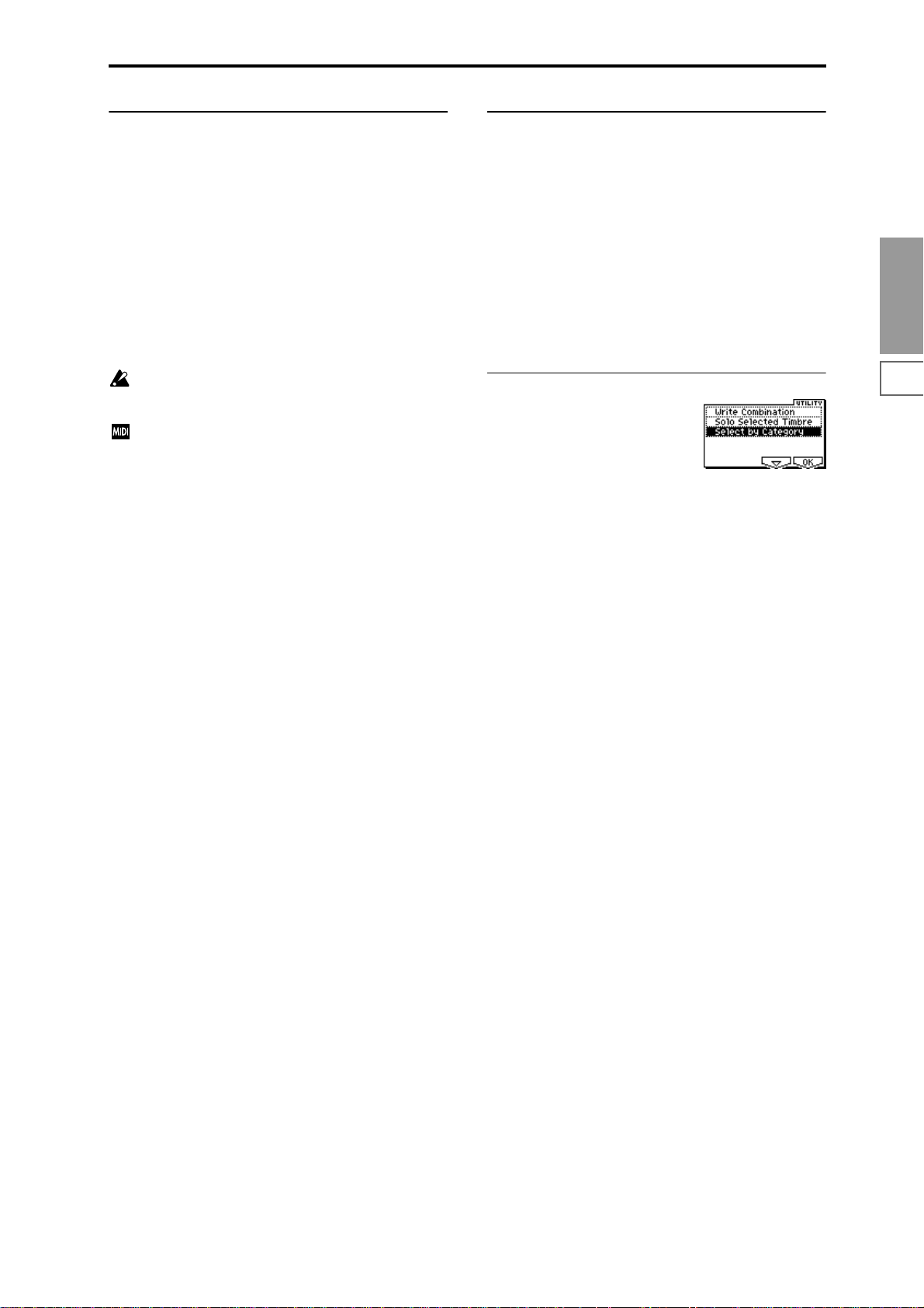
1.1–2c: Program Select, Program Name
1.1–2d: Selected Timbre Information
Program Select [I-A000...E-H127]
Selects the program that will be used by each timbre.
When “Program Select” is selected, you can use the [BANK]
key, numeric keys [0]–[9], [VALUE] dial, and [INC], [DEC]
keys to select a program.
You can move to timbres “T1”–“T8” by holding down the
[TIMBRE/TRACK] key and pressing one of the [F1](1/9)–
[F8](8/16) keys.
“Program Select” settings can also be made in the Prog page
of 2.1: Ed-Prog/Mix.
You can also use Utility “Select by Category” to select programs by category.
Bank I–F can be selected if you have installed the separately sold EXB-MOSS option. When installed, the 128
special EXB-MOSS programs will be available.
If bank select and program change messages are
received on a MIDI channel that matches the MIDI
channel of a timbre whose “Status” is INT, the program
of that timbre will change. However if the MIDI channel of the incoming message matches the global MIDI
channel “MIDI Channel,” then the combination will
change.
If you do not want the combination to change, you can
either change the global MIDI channel so that it does
not match the channel on which the program change
messages are being received, or you can uncheck
“Combi (Combi Change)” (GLOBAL 2.1–1b). Alternately, you can uncheck “Bank (Bank Change)” (GLOBAL 2.1–1b) so that only the program number will
change and the bank will remain the same.
If you wish to change a program without changing the
combination, you can also set “Program Change” (4.1–
1a) so that the program will change on certain timbres
but not on others.
When you select a combination on the TRITON-Rack, a
MIDI program change for the selected combination
number will be transmitted on the global MIDI channel
“MIDI Channel” (GLOBAL 2.1–1a). At the same time,
bank select, program change, and volume (CC#7) messages will be transmitted on the MIDI channel specified
for each timbre that is set to “Status” (3.1–1a) of EXT or
EX2. However, these messages will not be transmitted
for timbres that are set to the same MIDI channel as the
global MIDI channel. In this case, EX2 timbres will
show the “Program Select” Bank as “–”, and will transmit the bank number that was specified in “Bank (EX2)
MSB”and “Bank (EX2) LSB” (3.1–1a).
MIDI messages transmitted when you operate the TRITON are transmitted on the global MIDI channel. At
the same time, timbres whose “Status” is EXT or EX2
will transmit the same messages on their own MIDI
channel.
This shows information on the timbre (1–8) that is currently
selected for editing.
Timbre No.: Bank No., Prog No.: and name
This shows the timbre number , and the program bank, number and name selected for that timbre.
Status (INT, Off, EXT, EX2)
This shows the MIDI and internal tone generator status for
each track.
Ch (01...16, Gch)
This is the MIDI channel number specified for the timbre.
■ 1.1–2e: UTILITY
☞“Write Combination,” “Solo Selected Timbre” (1.1–1d)
For details on how to select the desired utility function, refer
to “PROG 1.1–1d: UTILITY.”
Select by Category
Combinations or the programs used by each timbre can be
selected by category.
If you have selected “Combi Select,” selecting Utility
“Select by Category” will access the Select Combination by
Category dialog box, allowing you to select a combination
by category. (
If you have selected “Program Select,” selecting Utility
“Select by Category” will access the Select Program by Category (Timbre) dialog box, allowing you to select a program
for each timbre by category.
For the procedure of selecting by category, refer to p.2.
☞p.32)
COMBI
1.1
2.12.22.33.13.23.33.44.14.24.34.46.17.17.27.3
Program Name
This displays part of the program name selected for the timbre. In the case of the GM2 variation bank or the GM2
drums bank, the variation bank (1)–(9) or drums bank (d)
will be indicated.
33
Page 41

1.1–3: Mix (Mixer)
Here you can set the pan and volume for each timbre 1–8.
1.1–3a
1.1–3b
1.1–3a: Pan, Volume
Pan [RND, L001...C064...R127]
Sets the pan for each timbre 1–8. (This parameter can also be
set from the Mixer page of 2.1: Ed-Prog/Mix.)
L001...C064...R127: A setting of L001 is far left and R127 is
far right. A setting of C064 will reproduce the pan setting
that was made for the oscillator in Program mode.
OSC1
Left
Left
Center
Center
OSC2
OSC1: Amp1 Pan=L001
OSC2: Amp2 Pan=R127
Right
Pan (CC#10)
C064
L032
L001
R096
R127
Right
OSC1: Amp1 Pan=L032
Left
Center
Left
Center
OSC2: Amp2 Pan=R096
Right
Pan (CC#10)
C064
L032
L001
R096
R127
Right
by a timbre that is set to the same MIDI channel as the
global MIDI channel. This message is transmitted on
the “MIDI Channel” (3.1–1a) specified for each timbre.
■ 1.1–3b: UTILITY
☞“Write Combination,” “Solo Selected Timbre,” “Select by
Category” (1.1–1d)
For details on how to select the desired utility function, refer
to “PROG 1.1–1d: UTILITY.”
Hold Balance
Adjusts the volume of the Combi while preserving the volume balance between timbres 1–8.
Selects the “Volume” of any timbre, select “Hold Balance”
from the Utility menu, and press the [F8] (“OK”) key. A
check mark will appear at the left of “Hold Balance.” (The
upper left of the LCD screen will indicate [Hold Bal.]) In this
state, adjusting any “Volume” value will simultaneously
change the volume of the other timbres as well, while preserving the volume balance between timbres 1–8.
1.1–4: Arp. A (Arpeggio Play A)
OSC1
Left
Left
Center
Center
OSC2
OSC1: Amp1 Pan=C064
OSC2: Amp2 Pan=C064
Right
Pan (CC#10)
C064
L032
L001
R096
R127
Right
If a mono-type insertion effect is inserted, the setting you
make here will be ignored. In this case, the “Pan (CC#8)”
parameter in 7.2: Ed–InsertFX, Setup page will adjust the
panning of the sound after the insertion effect (☞p.145 “3.
Mixer”).
RND: The oscillator pan will change randomly at each noteon.
If “Status” (3.1–1a) has been set to INT, MIDI control
change #10 (panpot) messages can be received to control the setting. CC#10 values of 0 or 1 will place the
sound at far left, 64 at center, and 127 at far right.
Pan can be controlled by messages received on the
“MIDI Channel” (3.1–1a).
Volume [000...127]
Adjusts the volume of each timbre 1–8. (This parameter can
also be set from the Mixer page of 2.1: Ed-Prog/Mix.)
The volume of each timbre is determined by multiplying this volume value with the MIDI volume (CC#7)
and expression (CC#11). If “Status” (3.1–1a) has been
set to INT, incoming MIDI CC#7 or CC#11 messages
will control the volume of a timbre. (However these
messages will not affect the setting of this parameter.)
If “Status” is EXT or EX2, the value of this parameter
will be transmitted as MIDI CC#7 when the combination is changed. However this will not be transmitted
1.1–5: Arp. B (Arpeggio Play B)
Here you can make arpeggiator settings for the combination. A combination can run two arpeggiators simultaneously. Arpeggiator parameters can be edited in 6.1: EditArp., but certain major parameters can be edited in these
pages as well. You can edit these parameters in realtime, for
example by changing the arpeggio pattern while playing in
COMBI 1.1: Play.
To save the edits you make, use “Write Combination.” The
arpeggiator can also be edited in realtime by the REAL TIME
CONTROLS C-mode [TEMPO] knob, [ARP-GATE] knob,
and [ARP-VELOCITY] knob.
1.1–4a
1.1–4b
1.1–4c
1.1–4(5)a: Arpeggiator Run, Timbre assign
Arpeggiator Run A, B (Run A, B) [Off, On]
When the [ARP ON/OFF] key is on, the arpeggiator that is
checked here will run if it is assigned to a timbre in “Assign”
(6.1–1b).
Even if the arpeggiator is on, you can turn A and B on/off
independently.
(This parameter can also be set from the 6.1: Ed-Arp. Setup
page.)
Timbre assign
This displays the timbres 1–8 to which arpeggiators A and B
are assigned. This can be set in “Assign” (6.1–1b).
34
Page 42
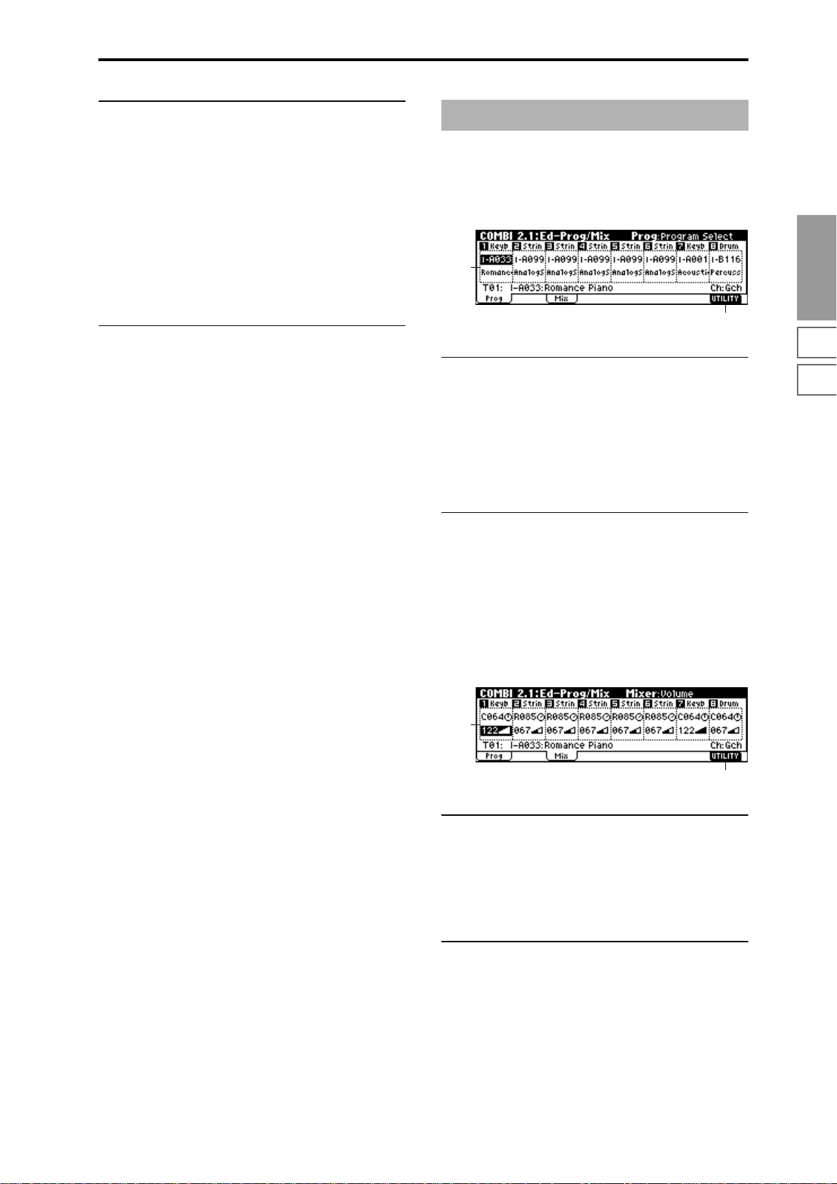
1.1–4(5)b: Arpeggiator A(B)
Pattern [P000....P004, U000(I-A/B)...U327(E-H)]
Reso (Resolution) [ , , , , , ]
Octave [1, 2, 3, 4]
Sort [Off, On]
Latch [Off, On]
Key Sync. [Off, On]
Keyboard [Off, On]
Sets the various parameters of the combination arpeggiator
(
☞“PROG: Ed–Arp.”). These parameters can also be set in
COMBI 6.1: Ed-Arp.
■ 1.1–4(5)c: UTILITY
☞“Write Combination,” “Solo Selected Timbre,” “Select by
Category” (1.1–1d)
COMBI 2.1: Ed–Prog/Mixer
2.1–1: Prog (Timbre Program)
Selects the bank and program for each timbre 1–8. These
parameters can also be set from the 1.1: Play, Prog page.
2.1–1a
2.1–1b
2.1–1a: Program Select, Program Name
Program Select
Selects the program that will be used by each timbre. (☞1.1–
2c)
Program Name
This displays part of the program name selected for each
timbre. (
☞1.1–2c)
COMBI
1.1
2.12.22.33.13.23.33.44.14.24.34.46.17.17.27.3
■ 2.1–1b: UTILITY
☞“Write Combination,” “Solo Selected Timbre” (1.1–1d),
“Select by Category”: Select Program by Category (Timbre) (1.1–2e)
2.1–2: Mix (Mixer)
Specifies the pan and volume for each timbre 1–8. These
parameters can also be set from the 1.1: Play, Mixer page.
2.1–2a
2.1–2b
2.1–2a: Pan, Volume
Pan
Sets the pan of each timbre 1–8. (☞1.1–3a)
Volume
Sets the volume of each timbre 1–8. (☞1.1–3a)
■ 2.1–1b: UTILITY
☞“Write Combination,” “Solo Selected Timbre” (1.1–1d)
35
Page 43

COMBI 2.2: Ed–Ctrl
Here you can set the Combination mode functions of the Bmode functions of REALTIME CONTROLS knobs [1]–[4],
and “SW1,” “SW2.”
2.2–1: Ctrls (Controls)
2.2–1a
COMBI 3.1: Ed–Param1
3.1–1: MIDI
Here you can make MIDI settings for each timbre.
3.1–1a
3.1–1b
2.2–1c2.2–1b
2.2–1a: Knob B Assign
These settings assign functions (mainly various control
changes) to the “B” mode of the REALTIME CONTROLS
knobs [1]–[4] (
List”).
The functions you specify here will be controlled when you
operate the REALTIME CONTROLS knobs [1]–[4] in “B”
mode.
Since the REALTIME CONTROLS knob [1]–[4] function of
the B-mode assignments made for the program assigned to
each timbre are not valid for the combination, they must be
newly set by these parameters.
☞p.214 “Realtime Control Knobs B Assign
Knob1–B (Knob1–B Assign) [Off, ..., MIDI CC#95]
Knob2–B (Knob2–B Assign) [Off, ..., MIDI CC#95]
Knob3–B (Knob3–B Assign) [Off, ..., MIDI CC#95]
Knob4–B (Knob4–B Assign) [Off, ..., MIDI CC#95]
2.2–1b: SW1/2 Assign
These settings assign the function of the “SW1” and “SW2”
(
☞p.213 “SW1, SW2 Assign List”).
Since the function assignments of the “SW1” and “SW2”
made for the program assigned to each timbre are not valid
for the combination, they must be newly set by these parameters.
3.1–1a: Status, MIDI Channel, Bank(EX2) MSB/LSB
Status [INT, Off, EXT, EX2]
Specifies the status of MIDI and the internal tone generator
for each track.
INT: The TRITON-Rack will produce sound in response to
MIDI messages from a connected MIDI device. MIDI data
will not be transmitted. If the arpeggiator has been specified
for a timbre that is set to INT, only the internal tone genera-
tor will sound, and MIDI messages will not be transmitted
to an external device.
Off: The program will not sound, nor will MIDI messages
be transmitted.
EXT: The TRITON-Rack will not produce sound, but will
transmit MIDI messages to an external device. If the arpeggiator has been specified for a timbre that is set to EXT, MIDI
messages will be transmitted, but the internal tone generator
will not sound. If you operate the controllers of the TRITON-Rack, the internal tone generator will not be controlled, but MIDI messages will be transmitted to control an
external MIDI device.
EX2: “Bank (EX2) MSB” and “Bank (EX2) LSB” (3.1–1a) will
be enabled. Instead of the bank numbers for I-A–E-H that
can be selected on the TRITON-Rack, the bank numbers you
specify here will be transmitted via MIDI. In other respects
this is the same as EXT.
INT
The TRITON-Rack’s Controllers
MIDI IN
Arpeggiator
Tone
generator
SW1 (SW1 Assign) [Off, ..., AfterT Lock :N/A]
SW1 Mode [Toggle, Momentary]
SW2 (SW2 Assign) [Off, ..., AfterT Lock :N/A]
SW2 Mode [Toggle, Momentary]
(☞PROG 2.2–1b)
■ 2.2–1c: UTILITY
☞“Write Combination,” “Solo Selected Timbre” (1.1–1d)
COMBI 2.3: Ed–MOSS
This page is displayed if the separately sold EXB-MOSS
option is installed.
☞EXB-MOSS owner’s manual & p.251 “EXB-MOSS
(
option”)
36
EXT, EX2
The TRITON-Rack’s Controllers
MIDI IN
MIDI OUT
Arpeggiator
MIDI Channel [01...16, Gch]
Set the MIDI transmit/receive channel for each timbre 1–8.
Gch: The timbre will use the channel that has been selected
as the global MIDI channel “MIDI Channel” (GLOBAL 2.1–
1a).
When “Status” is INT, MIDI messages will be received on
the channel you specify here. If this is set to EXT or EX2,
playing the TRITON-Rack will transmit MIDI messages on
the MIDI channel specified here. (Messages will also be
transmitted simultaneously on the global MIDI channel.)
Page 44

Bank(EX2) MSB [000:000...127:127]
Bank(EX2) LSB [000:000...127:127]
Specifies the bank number that will be transmitted when
“Status” is set to EX2. If “Status” is not set to EX2, this set-
ting has no effect.
■ 3.1–1b: UTILITY
☞“Write Combination,” “Solo Selected Timbre” (1.1–1d)
3.1–2: OSC
These settings specify how each timbre will be sounded.
■ 3.1–2b: UTILITY
☞“Write Combination,” “Solo Selected Timbre” (1.1–1d)
3.1–3: Pitch
Here you can make pitch-related settings for each timbre.
3.1–3a
COMBI
3.1–3b
3.1–2a
3.1–2b
3.1–2a: Force OSC Mode, OSC Select, Portamento
Force OSC Mode [PRG, Poly, Mono, LGT]
Specifies the “Mode (V oice Assign Mode)” (PROG 2.1–1b) of
the program selected for each timbre 1–8.
PRG: The settings of the program will be used.
Poly: The timbre will play polyphonically, regardless of the
settings of the program.
Mono: The timbre will play monophonically, regardless of
the settings of the program.
LGT (Legato): The timbre will play monophonically, with
single triggering (legato).
With settings of Mono or LGT, the note priority will be
according to the “Priority” (PROG 2.1–1b) setting of the program.
OSC Select [Both, OSC1, OSC2]
Specify the “Mode (Oscillator Mode)” (PROG 2.1–1a) of the
program selected for each timbre 1–8. If the “Mode (Oscillator Mode)” is Double, you can specify that either or both
oscillators sound.
Both: OSC1 and 2 will sound as specified by the settings of
the program.
OSC1: Only OSC1 will sound.
OSC2: Only OSC2 will sound. If “Mode (Oscillator Mode)”
is Single or Drums, there will be no sound.
Portamento [PRG, Off, 001...127]
Indicates portamento settings for each timbre 1–8.
PRG: Portamento will be applied as specified by the pro-
gram settings.
Off: Portamento will be off, even if the original program settings specified for it to be on.
001...127: Portamento will be applied with the portamento
time you specify here, even if it is turned off by the program
settings.
If the “Status” (3.1–1a) is set to INT, CC#05 (portamento time) and CC#65 (portamento switch) messages
will be received to control and change this setting. (If
the setting is PRG, CC#05 portamento time will not be
received.) These messages will be received on the MIDI
channel specified for each timbre by “MIDI Channel”
(3.1–1a).
3.1–3a: Transpose, Detune, Bend Range
Transpose [–24…+24]
Adjusts the pitch of each timbre in semitone steps.
12 units equal one octave.
Detune (BPM Adj) [–1200...+1200]
Adjusts the pitch of each timbre in one-cent units.
0: Normal pitch.
Y ou can also use the Utility “Detune BPM Adj.” (3.1–3b)
page menu command to automatically make a detune
setting from a calculation in BPM units.
“Transpose” and “Detune” can be controlled via MIDI
RPN messages. Depending on the “Mode (Oscillator
Mode)” (PROG 2.1–1a) settings of the programs used
by timbres 1–8, they can be controlled as follows.
When “Mode (Oscillator Mode)” is Single or Double
MIDI RPN Coarse Tune can be received to control and
change the setting of “Transpose,” and RPN Fine Tune
can be received to control and change the setting of
“Detune.”
When “Mode (Oscillator Mode)” is Drums
MIDI RPN Coarse Tune and Fine Tune can be received
to control and change the setting of “Detune.” The controllable range is ±1 octave for coarse tune and fine tune
together.
Bend Range [PRG, –24...+24]
Specifies the range of pitch change that will occur when
pitch bend changes are received, in semitone units.
PRG: The pitch range specified by the program will be used.
–24–+24: This setting will be used regardless of the setting in
the program.
The MIDI RPN Pitch Bend Change message can be
received to control this and change the setting. (However it will not be received if this parameter is set to
PRG.) This message is received on the MIDI channel for
each timbre set by “MIDI Channel” (3.1–1a).
1.1
2.12.22.33.13.23.33.44.14.24.34.46.17.17.27.3
37
Page 45
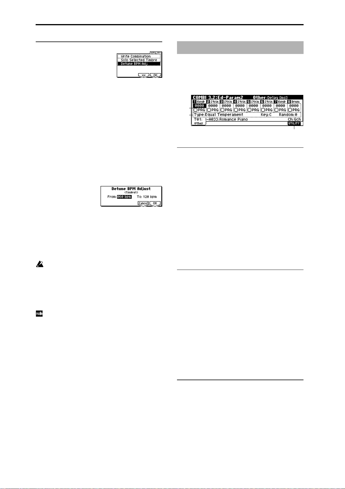
■ 3.1–3b: UTILITY
☞“Write Combination,” “Solo Selected Timbre” (1.1–1d)
For details on how to select the desired utility function, refer
to “PROG 1.1–1d: UTILITY.”
Detune BPM Adj. (Detune BPM Adjust)
If the program of a timbre uses a phrase or rhythm loop
multisample or sample that was created in Sampling mode
to a specific BPM (or was loaded in Disk mode), you can use
this Utility to modify its BPM value. “Detune BPM Adj.”
changes the BPM of a phrase or rhythm by modifying its
pitch.
This is valid for a track when timbre “Detune” is selected.
When this Utility is executed, the selected “Detune” value
will be set automatically. (
5.1–1b, 5.1–2)
1 Select “Detune BPM Adj.” to access the dialog box.
2 In “From” specify the original BPM value. In “To” specify
the desired BPM value. The appropriate “Detune” value
will be calculated automatically from these two values.
For example if you set “From” to 60bpm and “To” to
120bpm, the “Detune” parameter will be set to +1200
(one octave up).
3 To execute the Detune BPM Adjust command, press the
[F8] (“OK”) key. To cancel, press the [F7] (“Cancel”) key.
The detune value that is calculated when you execute
this command will be added to “Detune” +0000. Y ou
must set the “From” BPM value to the value when
“Detune” is +0000. For example if you execute “From”
60bpm “To” 120bpm, and then execute “From”
120bpm “To” 60bpm, will not return to the original
result. (Rather , this will set Detune= –1200, which is one
octave down.)
This command is valid when “Detune” (3.1–3a) is
selected.
☞PROG 2.1–2c, 2.1–3, GLOBAL
COMBI 3.2: Ed–Param2
3.2–1: Other
Specifies the delay from note-on until sound is produced for
each timbre. Also specifies the scale.
3.2–1a
3.2–1b
3.2–1c
3.2–1a: Delay [ms], Use Prog’s Scale
Delay [ms] [0000…5000, KeyOff]
Specifies a delay time from note-on until the sound begins
for each timbre.
KeyOff: The note will begin sounding at note-off. In this
case, the sound will not die away if the sustain level of the
program’s amp EG is other than 0. This setting is used when
creating harpsichord sounds.
Normally you will set this to 0.
Use Prog’s Scale [Off, On]
Each timbre can use the scale that is specified by “Scale”
(PROG 2.1–1c).
On (Checked): The scale specified by the program will be
used.
Off (Unchecked): The scale specified by “Type (Combi’s
Scale)” (3.2–1b) will be used.
3.2–1b: Combi’s Scale, Key, Random
Specifies the scale that the combination will use.
Type (Combi’s Scale)
[Equal Temperament...User Octave15]
Selects the type of scale .
☞“Type (Scale Type)” (PROG 2.1–1c)
Key [C…B]
Selects the tonic key of the selected scale.
☞“Key” (PROG 2.1–1c)
38
Random [0…7]
As this value is increased, an increasingly random deviation will be added to the pitch at each note-on.
☞“Random” (PROG 2.1–1c)
■ 3.2–1c: UTILITY
☞“Write Combination,” “Solo Selected Timbre” (1.1–1d)
Page 46
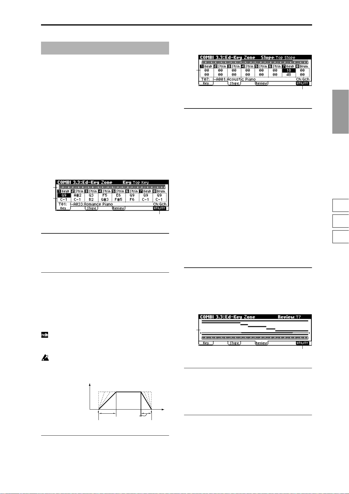
COMBI 3.3: Ed–Key Zone
These settings specify the keyboard range in which each
timbre will sound.
The top/bottom key parameters specify the range of notes
in which timbres 1–8 will sound, and the top/bottom slope
parameters specify the range over which the original volume will be reached.
By setting timbres of different sounds to ranges that do not
overlap, you can play different sounds in different ranges of
the keyboard (Key Split).
By setting the ranges to overlap, you can play two or more
sounds with a single note (Layer).
If you set the slopes (the grayed portion) to overlap, the
sounds will overlap, and the proportion of the overlap will
change according to the keyboard location (Positional
Cross-fade).
3.3–1: Key (Key Zone)
3.3–1a
3.3–1b
3.3–1c
3.3–1a: Key Zone Map (1)
This displays the range of note data that will sound the currently selected track. The range of notes sounded is shown
as a line, and the slope portion is shaded.
3.3–2: Slope (Key Slope)
3.3–2a
3.3–2b
3.3–2a: Top Slope, Bottom Slope
Top Slope [00...72]
Specifies the range of keys (12 is one octave) over which the
volume will be reached starting from the top key.
0: The volume will be at the original level from the top key.
12: The volume will increase gradually as you play down-
ward, and will reach the original volume one octave below
the top key.
60: The volume will increase gradually as you play downward, and will reach the original volume five octaves below
the top key.
Bottom Slope [00...72]
Specifies the range of keys (12 is one octave) over which the
volume will be reached starting from the bottom key.
0: The volume will be at the original level from the bottom
key.
12: The volume will increase gradually as you play upward,
and will reach the original volume one octave above the bottom key.
60: The volume will increase gradually as you play upward,
and will reach the original volume five octaves above the
bottom key.
COMBI
1.1
2.12.22.33.13.23.33.44.14.24.34.46.17.17.27.3
3.3–1b: Top Key, Bottom Key
Top Key [C–1...G9]
Specifies he top key (upper limit) of the notes that will
sound each timbre 1–8.
Bottom Key [C–1...G9]
Specifies the bottom key (lower limit) of the notes that will
sound each timbre 1–8.
You can also set this parameter by holding down the
[ENTER] key and playing a note on a connected MIDI
instrument.
It is not possible to set the bottom key above the top key
of the same timbre. Nor is it possible for the top and
bottom slopes to overlap.
How volume will change according to keyboard location
Volume
Key
■ 3.3–1c: UTILITY
Bottom Slope
Bottom Key Top Key
Top Slope
■ 3.3–2b: UTILITY
☞“Write Combination,” “Solo Selected Timbre” (1.1–1d)
3.3–3: Review
3.3–3a
3.3–3b
3.3–3a: Key Zone Map (All)
T1...T8
This displays the range of note data that will sound timbres
1–8. The range of notes sounded is shown as a line, and the
slope portion is shaded.
■ 3.3–3b: UTILITY
☞“Write Combination,” “Solo Selected Timbre” (1.1–1d)
☞“Write Combination,” “Solo Selected Timbre” (1.1–1d)
39
Page 47
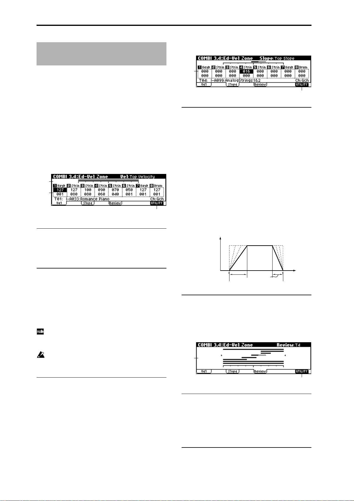
COMBI 3.4: Ed–Vel Zone
(Velocity Zone)
3.4–2: Slope (Velocity Slope)
Sets the Top/Bottom Velocity parameters to specify the
range of velocities that will sound each timbre 1–8, and sets
the Top/Bottom Slope parameters to specify the range over
which the volume will change.
By setting two or more timbres to velocity zones that do not
overlap, you can use variations in playing dynamics to play
different sounds (Velocity Switch).
If you set two or more timbres to velocity zones that overlap,
the sounds will be heard together (Layer).
If the slope ranges (gray line) overlap, different sounds will
be sounded together, and your playing dynamics will determine the proportion of each sound (Velocity Cross-fade).
3.4–1: Vel (Velocity Zone)
3.4–1a
3.4–1b
3.4–1c
3.4–1a: Velocity Zone Map (1)
This displays the range of velocities that will sound the currently selected timbre. The range of velocities sounded is
shown as a line, and the slope portion is shaded.
3.4–2a
3.4–2b
3.4–2a: Top Slope, Bottom Slope
Top Slope [0…120]
Specifies the number of velocity steps over which the original volume will be reached, starting from the Top Velocity.
0: The volume will be at the original value from the top
velocity.
120: The volume will decrease as the velocity approaches the
top velocity.
Bottom Slope [0…120]
Specifies the number of velocity steps over which the original volume will be reached, starting from the Bottom Velocity.
0: The volume will be at the original value from the bottom
velocity.
120: The volume will decrease as the velocity approaches the
bottom velocity.
How volume will change according to keyboard location
Volume
3.4–1b: Top Velocity, Bottom Velocity
Top Velocity [1…127]
Specifies the maximum velocity value that will sound each
timbre 1–8.
Bottom Velocity [1…127]
Specifies the minimum velocity value that will sound each
timbre 1–8.
You can also set this parameter by holding down the
[ENTER] key and playing a note on a connected MIDI
instrument.
It is not possible to set the bottom velocity greater than
the top velocity for the same timbre. Nor can the top
slope and the bottom slope overlap.
■ 3.4–1c: UTILITY
☞“Write Combination,” “Solo Selected Timbre” (1.1–1d)
Bottom Slope
Bottom Velocity Top Velocity
■ 3.4–2b: UTILITY
☞“Write Combination,” “Solo Selected Timbre” (1.1–1d)
Top Slope
Velocity
3.4–3: Review
3.4–3a
3.4–3b
3.4–3a: Velocity Zone Map (All)
T1...T8
Specify the range of velocities for which each timbre will
sound.
The range of velocities sounded is shown as a line, and the
slope portion is shaded.
40
■ 3.4–3b: UTILITY
☞“Write Combination,” “Solo Selected Timbre” (1.1–1d)
Page 48

COMBI 4.1: Ed–MIDI Filter1
These settings allow you to apply filters to the MIDI data
that will be transmitted and received by each timbre 1–8. For
example even if two timbres are being played by the same
MIDI channel, you can make settings so that the damper
pedal will apply to one but not the other.
On (Checked): Transmission and reception of MIDI data is
enabled.
When “Status” (3.1–1a) is INT, operations of the built-in
controllers or incoming MIDI data will apply the effect of
the checked item to the program of the corresponding timbre. (The effect dynamic modulation function is not affected
by this setting.) When “Status” is EXT or EX2, operations of
the built-in controllers will transmit MIDI data on the channel of that timbre. MIDI transmission and reception settings
for the entire TRITON are made in “MIDI Filter” (GLOBAL
2.1–1b).
The MIDI 3 and MIDI 4 pages contain MIDI filters for
assignable controllers (whose function can be set by the
user), and if these are assigned to MIDI control changes, the
filter settings will affect those control changes.
If the function of the REALTIME CONTROLS knobs,
“SW1,” and “SW2” has been assigned to a MIDI control
change, the MIDI filters for these controllers (MIDI Filter 3,
4) will apply to those control changes. However if these
coincide with the control changes of MIDI Filter 1, 2, the
MIDI Filter 1, 2 settings will be given priority. Furthermore,
if the same control change has been assigned to two or more
controllers, the setting will be valid for that control change if
any single item is checked in either MIDI Filter 3 or 4.
Off (Unchecked): Transmission and reception of MIDI data
is disabled.
4.1–2: MIDI 1–2 (MIDI Filter 1–2)
4.1–2a
4.1–2b
4.1–2a: Damper CC#64, Portamento SW CC#65
Damper CC#64 [Off, On]
Specifies whether or not MIDI control change message #64
hold (damper pedal) messages will be transmitted and
received.
Portamento SW CC#65 [Off, On]
Specifies whether or not MIDI control change message #65
portamento on/off messages will be transmitted and
received.
■ 4.1–2b: UTILITY
☞“Write Combination,” “Solo Selected Timbre” (1.1–1d)
COMBI 4.2: Ed–MIDI Filter2
4.2–1: MIDI 2–1 (MIDI Filter 2–1)
COMBI
1.1
2.12.22.33.13.23.33.44.14.24.34.46.17.17.27.3
4.1–1: MIDI 1–1 (MIDI Filter 1–1)
4.1–1a
4.1–1b
4.1–1a: Program Change, After Touch
Program Change [Off, On]
Specifies whether or not MIDI program change messages
will be transmitted and received.
After Touch [Off, On]
Specifies whether or not MIDI after touch messages will be
received.
■ 4.1–1b: UTILITY
☞“Write Combination,” “Solo Selected Timbre” (1.1–1d)
4.2–1a
4.2–1b
4.2–1a: JS+Y CC#01, JS–Y CC#02
JS+Y CC#01 [Off, On]
Specifies whether MIDI control change message #1 (selected
as assignment B for REALTIME CONTROLS [1]–[4] knobs,
or the +Y axis of the joystick on a TRITON etc.) will be transmitted and received.
JS–Y CC#02 [Off, On]
Specifies whether MIDI control change message #2 (selected
as assignment B for REALTIME CONTROLS [1]–[4] knobs,
or the –Y axis of the joystick on a TRITON etc.) will be transmitted and received.
■ 4.2–1b: UTILITY
☞“Write Combination,” “Solo Selected Timbre” (1.1–1d)
41
Page 49
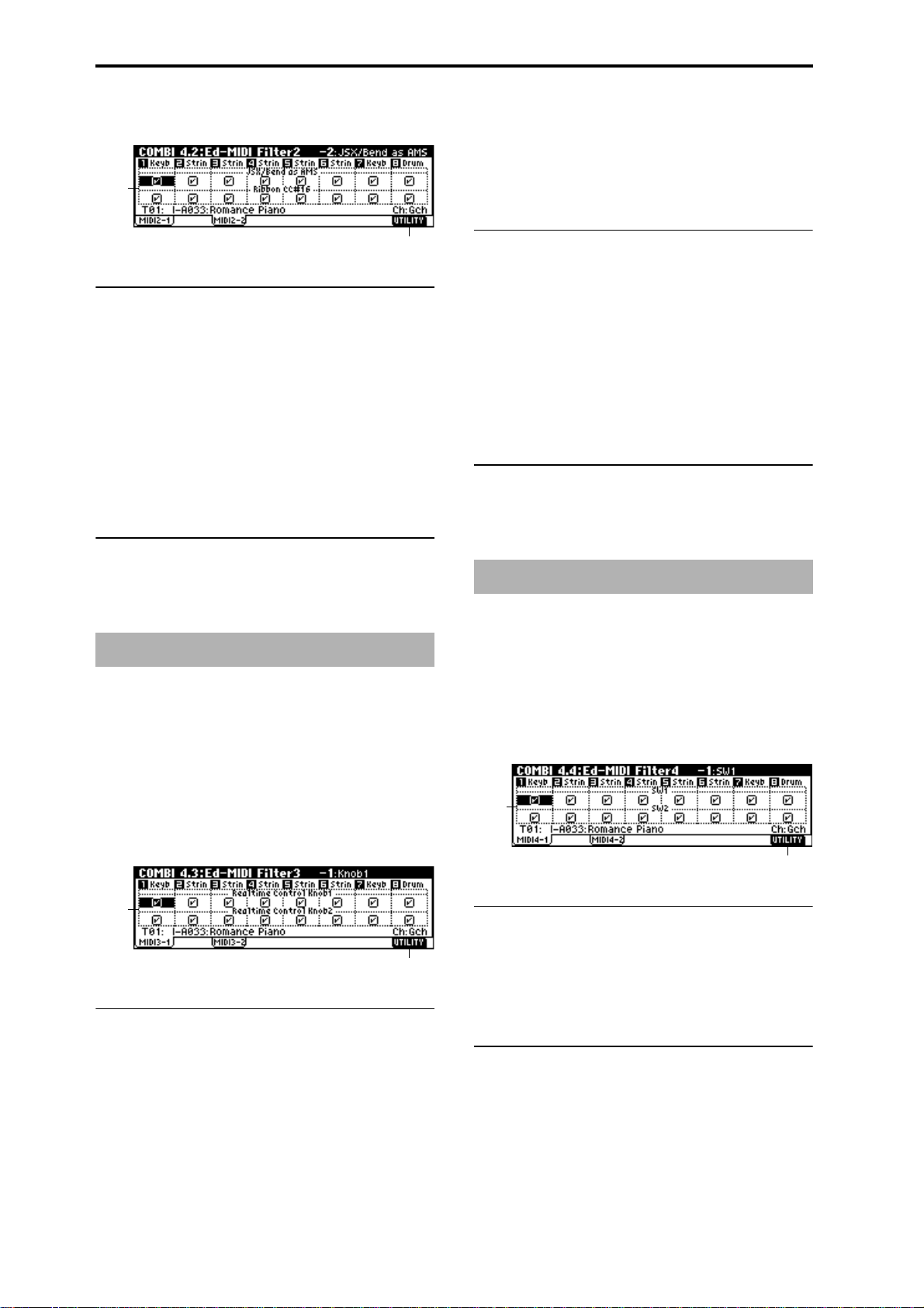
4.2–2: MIDI 2–2 (MIDI Filter 2–2)
4.2–2a
Knob2 [Off, On]
Specifies whether MIDI control change message #71 (internal low pass filter resonance or high pass filter cutoff frequency) for the A mode of knob [2] and the MIDI control
change message assigned to the B mode of knob [2] will be
transmitted and received.
4.2–2b
4.2–2a: JS X/Bend as AMS, Ribbon CC#16
JS X/Bend as AMS [Off, On]
Specifies whether MIDI pitch bend messages (the X axis of
the joystick on a TRITON etc.) will be received as the AMS
(
☞p.205 “Alternate Modulation Source”) for which JS X is
selected. (This is not a filter for MIDI pitch bend message
reception.)
Ribbon CC#16 [Off, On]
Specifies whether MIDI control change message #16
(selected as assignment B for REALTIME CONTROLS [1]–
[4] knobs, or assigned to the ribbon controller of a TRITON
etc.) will be received.
■ 4.2–2b: UTILITY
☞“Write Combination,” “Solo Selected Timbre” (1.1–1d)
COMBI 4.3: Ed–MIDI Filter3
Specifies whether the A and B mode effects of REALTIME
CONTROLS knobs [1], [2], [3], and [4] will be transmitted
and received. The A mode of each knob is fixed as a MIDI
control message. For B mode, you can assign a message in
2.2: Ed-Ctrl.
4.3–2a: Realtime Control Knob 3, 4
Knob3 [Off, On]
Specifies whether MIDI control change message #79 (internal filter EG intensity) for the A mode of knob [3] and the
MIDI control change message assigned to the B mode of
knob [3] will be transmitted and received.
Knob4 [Off, On]
Specifies whether MIDI control change message #72 (internal filter and amp EG release time) for the A mode of knob
[4] and the MIDI control change message assigned to the B
mode of knob [4] will be transmitted and received.
■ 4.3–1(2)b: UTILITY
☞“Write Combination,” “Solo Selected Timbre” (1.1–1d)
COMBI 4.4: Ed–MIDI Filter4
Specifies whether the effects of “SW1” and “SW2” will be
transmitted and received. “SW1” and “SW2” correspond to
the messages specified in 2.2: Ed-Ctrl. You can also specify
whether other control change messages will be transmitted
and received.
4.4–1: MIDI 4–1 (MIDI Filter 4–1)
4.3–1: MIDI 3–1 (MIDI Filter 3–1)
4.3–2: MIDI 3–2 (MIDI Filter 3–2)
4.3–1a
4.3–1a: Realtime Control Knob 1, 2
Knob1 [Off, On]
Specifies whether MIDI control change message #74 (internal low pass filter cutoff frequency) for the A mode of knob
[1] and the MIDI control change message assigned to the B
mode of knob [1] will be transmitted and received.
42
4.3–1b
4.4–1a
4.4–1b
4.4–1a: SW1, SW2
SW1, SW2 [Off, On]
Specifies whether or not the effect of the “SW1” and “SW2”
will be transmitted and received.
This filter setting is valid for settings of SW1 Mod.(CC#80),
SW2 Mod.(CC#81), or Porta.SW(CC#65).
■ 4.4–1b: UTILITY
☞“Write Combination,” “Solo Selected Timbre” (1.1–1d)
Page 50

4.4–2: MIDI 4–2 (MIDI Filter 4–2)
4.4–2a
4.4–2b
4.4–2a: Other Control Change
Other Ctrl Change [Off, On]
Specifies whether or not MIDI control change message not
covered in the preceding items MIDI Filter 1–4 will be transmitted and received.
COMBI 6.1: Ed–Arp. (Arpeggiator)
These parameters specify how the arpeggiator will function
within the combination. Two arpeggiators can be running
simultaneously.
This offers a variety of possibilities, such as applying separate arpeggio patterns to two sounds that have been
assigned as a keyboard split, or using velocity to switch
between two arpeggio patterns.
6.1–1: Setup
6.1–1a
6.1–1b
COMBI
1.1
■ 4.4–2b: UTILITY
☞“Write Combination,” “Solo Selected Timbre” (1.1–1d)
6.1–1c
6.1–1a: Arpeggiator Run,
Arpeggiator Run A, B (Run A, B)
When the [ARP ON/OFF] key is on, the arpeggiator(s)
checked here will run if they are assigned to a timbre by
“Assign” (6.1–1b). (
☞1.1–4(5)a)
(Tempo) [040...240, EXT]
Set the tempo of the arpeggiator. This can also be adjusted
by the [TEMPO] knob. (
☞1.1–1a)
6.1–1b: Assign
Assign [Off, A, B]
Assigns arpeggiator A or B to each timbre 1–8. When the
[ARP ON/OFF] key is on, the arpeggiator specified for each
timbre will operate according to “Arpeggiator Run” and
these settings.
Off: The arpeggiator will not operate.
A: Arpeggiator A will operate. Make settings in the Arp. A
page to select the arpeggio pattern and set parameters.
B: Arpeggiator B will operate. Make settings in the Arp. B
page to select the arpeggio pattern and set parameters.
If the “Status” (3.1–1a) of the timbre is INT, each timbre
1–8 to which arpeggiator A or B is assigned will be
sounded by the note data generated by the arpeggiator,
regardless of the “MIDI Channel” (3.1–1a) setting of the
timbre. If a timbre is set to EXT or EX2, MIDI note data
will be transmitted on the “MIDI Channel” of each timbre.
In this case, the arpeggiator can be triggered (operated)
by any MIDI channel specified for the “MIDI Channel”
parameter of any timbre 1–8 assigned to arpeggiator A
or B.
You can control the arpeggiator from an external
sequencer, or use an external sequencer to r ecor d arpeggio note data. (
☞p.228)
2.12.22.33.13.23.33.44.14.24.34.46.17.17.27.3
43
Page 51
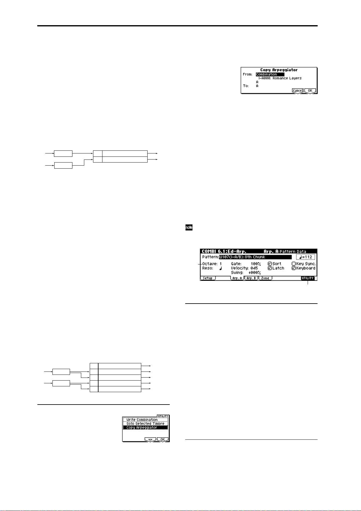
Example 1)
1 Set the “MIDI Channel” (3.1–1a) of timbres 1 and 2 to
Gch, and set “Status” (3.1–1a) to INT.
2 Assign arpeggiator A to timbre 1 and arpeggiator B to
timbre 2, and check “Arpeggiator Run” (1.1–4a/5a, 6.1–
1a).
3 Set the MIDI channel of the external MIDI device trans-
mitting the note data to match the Global MIDI channel
“MIDI Channel” (GLOBAL 2.1–1a).
4 When the [ARP ON/OFF] key is off, playing the key-
board of the connected MIDI device will sound timbres 1
and 2 simultaneously (Layer).
When the [ARP ON/OFF] key is on, playing the keyboard of the connected MIDI device will cause arpeggiators A and B to independently control and play timbres 1
and 2 respectively.
Arpeggiator
Trigger
= Gch
Trigger
= Gch
Arpeggiator
A
Arpeggiator
B
Pattern - A
Pattern - B
Assign
A
Timbre 1 MIDI Ch=Gch Status=INT
B
Timbre 2 MIDI Ch=Gch Status=INT
Pattern - A
Pattern - B
Example 2)
1 The “MIDI Channel” (3.1–1a) of timbres 1, 2, 3, 4, and 5
are set respectively to Gch, Gch, 02, Gch, and 03. Their
“Status” (3.1–1a) is set respectively to INT, Off, INT, Off,
and INT.
2 Assign arpeggiator A to timbres 2 and 3, assign arpeggia-
tor B to timbres 4 and 5, and check “Arpeggiator Run”
(1.1–4a/5a, 6.1–1a).
3 Set the MIDI channel of the external MIDI device trans-
mitting the note data to match the Global MIDI channel
“MIDI Channel” (GLOBAL 2.1–1a).
4 When the [ARP ON/OFF] key is off, playing the key-
board of a connected MIDI device will sound only timbre
1. Timbres 2 and 4 ar e receiving the Gch, but they will not
sound since their “Status” is Off.
When you turn on the [ARP ON/OFF] key, arpeggiator
A will operate for timbres 2 and 3, and arpeggiator B will
operate independently for timbres 4 and 5. (Arpeggiators
A and B are trigger ed by receiving note data on any MIDI
channel of an assigned timbre, but in this example they
are being triggered from the Gch.)
When you play the keyboard of a connected MIDI
device, arpeggiator A will operate for timbres 2 and 3,
but only timbre 3 whose “Status” is INT will sound. Similarly, arpeggiator B will operate for timbres 4 and 5, but
only timbre 5 whose “Status” is INT will sound.
In this way, you can make settings so that a timbre does
not sound when the arpeggiator is off, but sounds only
when the arpeggiator is on.
Arpeggiator
Assign
Off
Trigger
= Gch, Ch2
Trigger
= Gch, Ch3
Arpeggiator
A
Arpeggiator
B
Pattern - A
Pattern - B
Timbre 1 MIDI Ch=Gch Status=INT
A
Timbre 2 MIDI Ch=Gch Status=Off
A
Timbre 3 MIDI Ch=2ch Status=INT
B
Timbre 4 MIDI Ch=Gch Status=Off
B
Timbre 5 MIDI Ch=3ch Status=INT
Sounded by normal
keyboard playing
Does not sound
Pattern - A
Does not sound
Pattern - B
■ 6.1–1c: UTILITY
Copy Arpeggiator
This command copies arpeggiator settings.
1 Select “Copy Arpeggiator” to access the dialog box.
2 In “From” select the copy source (mode, bank, number)
arpeggiator.
If you are copying from Combination, or Multi mode,
select either A or B to if you wish to copy settings from
only one arpeggiator, or select A&B if you wish to copy
the settings of both arpeggiators.
3 If you are copying from a Program, or are copying either
A or B from Combination, or Multi mode, select either A
or B as the “To” copy destination.
4 To execute the Copy Arpeggiator command, press the
[F8] (“OK”) key. To cancel without executing, press the
[F7] (“Cancel”) key.
6.1–2: Arp. A (Arpeggiator A)
6.1–3: Arp. B (Arpeggiator B)
The Arp. A pages you make settings for arpeggiator A. The
Arp. B pages you make settings for arpeggiator B.
Y ou can also use Utility “Copy Arpeggiator” (6.1–1c) to
copy settings from another mode such as Program
mode.
6.1–2a
6.1–2b
6.1–2(3)a: Arpeggiator-A(B) Setup
Pattern* [P000...P004, U000(I-A/B)...U327(E-H)]
Octave* [1, 2, 3, 4]
Reso (Resolution)* [ , , , , , ]
Gate [000...100%, Step]
Velocity [001...127, Key, Step]
Swing [–100...+100%]
Sort* [Off, On]
Latch* [Off, On]
Key Sync.* [Off, On]
Keyboard* [Off, On]
These parameters are the arpeggiator A settings for the combination.
(
☞PROG 6.1: Ed–Arp.)
* These parameters can also be set in “1.1–4: Arp. A, 1.1–5:
Arp. B”
☞“Write Combination,” “Solo Selected Timbre” (1.1–1d)
For details on how to select the desired utility function, refer
to “PROG 1.1–1d: UTILITY.”
44
■ 6.1–2(3)b: UTILITY
☞“Write Combination,” “Solo Selected Timbre” (1.1–1d),
“Copy Arpeggiator” (6.1–1c)
Page 52

6.1–4: Zone (Scan Zone)
These settings specify the note and velocity ranges that will
operate arpeggiators A and B.
6.1–4a
COMBI 7.1: Ed–BUS
Here you can specify the output bus for the program oscillator of each timbre 1–8. You can also specify the send level to
the master effects.
☞For details on insertion effects, refer to p.141 “8. Effect
Guide.”
6.1–4b
6.1–4a: Scan Zone A/B
Zone Map
This shows the “Scan Zone” for each arpeggiator, A and B.
Key zone of arpeggiator B
Key zone of arpeggiator A
C–1–G9
Velocity zone of
arpeggiator A
Velocity zone of
arpeggiator B
A: Key
Btm (A-Bottom Key) [C–1...G9]
Top (A-Top Key) [C–1...G9]
Specifies the range of notes (keys) that will operate arpeggiator A. “Top” specifies the upper limit, and “Btm” speci-
fies the lower limit.
A: Vel (Velocity)
Btm (A-Bottom Velocity) [001...127]
Top (A-Top Velocity) [001...127]
Specifies the range of velocities that will operate arpeggiator
A. “Top” specifies the upper limit, and “Btm” specifies the
lower limit.
B: Key
Btm (B-Bottom Key) [C–1...G9]
Top (B-Top Key) [C–1...G9]
B: Vel (Velocity)
Btm (B-Bottom Velocity) [001...127]
Top (B-Top Velocity) [001...127]
Specify the range of notes (keys) and velocities that will
operate arpeggiator B (
You can also set this parameter by holding down the
[ENTER] key and playing a note on a connected MIDI
instrument.
■ 6.1–4b: UTILITY
☞“Write Combination,” “Solo Selected Timbre” (1.1–1d),
“Copy Arpeggiator” (6.1–1c)
☞“A: Key,” “A: Vel”).
7.1–1: BUS
COMBI
7.1–1a
1.1
7.1–1b
2.12.22.33.13.23.33.44.14.24.34.46.17.17.27.3
7.1–1a: BUS Select, Send1(MFX1), Send2(MFX2)
BUS Select [DKit, L/R, IFX1...5, 1...4, 1/2, 3/4, Off]
Specifies the output bus for the program oscillator of each
timbre 1–8. The current setting status can be viewed in the
Route page.
DKit: This can be selected only if the program for which settings are being made is a drum program “Mode (Oscillator
Mode) Drums” (PROG 2.1–1a). With a setting of DKit, the
“BUS Select” (GLOBAL 5.1–3a) setting made for each key of
the drum kit will be used.
For example, if the “BUS Select” settings of the drum kit
have assigned Snare sounds to IFX1 and Kick sounds to
IFX2, setting this parameter to DKit will send the Snare
sounds to IFX1 and Kick sounds to IFX2. If you wish to
modify these routings, use Utility “DKit IFX Patch” (7.1–1b).
If this is set to 1/2 or 3/4, the programs of timbres 1–8
will be sent in stereo from AUDIO OUTPUT (INDIVIDUAL) 1/2 or 3/4. If the pan of the program oscillator is
controlled by MIDI control change #10 (pan) or AMS
(Alternate Modulation Source), the sound will be output with the pan setting that is in effect at the moment
of note-on. Unlike the case when this parameter is set to
L/R to output the sound from (MAIN) L/MONO and
R, the pan of a sounding note will not change in realtime.
If you wish to move the pan of a sounding note in realtime and output it from AUDIO OUTPUT (INDIVIDUAL) 1/2 or 3/4, you must set “BUS Select” to IFX1 (or
IFX2–IFX5), select 000: No Effect for “IFX1” (or IFX2–
IFX5) (7.2–1a), and for the sound that has passed
through the IFX, set “BUS Select” (7.2–1a) to either 1/2
or 3/4.
S1 (Send1(MFX1)) [000...127]
S2 (Send2(MFX2)) [000...127]
For each timbre 1–8, these parameters set the send level to
master effects 1 and 2. These settings are valid when “BUS
Select” is set to L/R or Off. When IFX 1, 2, 3, 4 or 5 are
selected, the send levels to master effects 1 and 2 are set by
the “S1 (Send1(MFX)), ” “S2 (Send2(MFX))” parameters of
the 7.2: Ed–InsertFX, Setup page, after the sound has passed
through IFX1–5.
If “BUS Select” is set to 1, 2, 3, 4, 1/2, or 3/4, these settings are
ignored.
45
Page 53

Control change #93 can be used to control the Send 1
level, and #91 to control the Send 2, and modify their
respective settings. These messages will be received on
the MIDI channel specified for each timbre in the 3.1:
Ed–Param1, MIDI page.
The actual send levels are determined by multiplying
this value with the send level “S1 (Send1(MFX)), ” “S2
(Send2(MFX))” (PROG 7.2–1a) for each oscillator of the
program selected for the timbre.
7.1–2: Route (Routing)
Specifies the bus to which the program used by each timbre
1–8 will be sent. Here you can also set the send levels to the
master effects.
7.1–2a
■ 7.1–1b: UTILITY
☞“Write Combination,” “Solo Selected Timbre” (1.1–1d)
For details on how to select the desired utility function, refer
to “PROG 1.1–1d: UTILITY.”
Copy Insert Effect
(☞PROG 7.1–1c)
However, the MIDI control channel specified for “Control
Channel” of the 7.2: Ed–InsertFX, Setup page will not be
copied.
Swap Insert Effect
(☞PROG 7.1–1c)
However, the MIDI control channel specified for “Control
Channel” of the 7.2: Ed–InsertFX, Setup page will not be
copied.
DKit IFX Patch (DrumKit IFX Patch)
This command applies a patch to the “BUS Select” settings
of each key of the drum kit, allowing you to temporarily
change the connections to the insert effects. This command
is available only if a drum program has been selected for the
timbre and the “BUS Select” (7.1–1a) parameter is set to
Dkit. Furthermore, this command can be executed only if
the “BUS Select” (GLOBAL 5.1–3a) for the individual keys
of that drum kit are set to IFX1–5.
1 Select “DKit IFX Patch” to access the dialog box.
7.1–2b
7.1–2a: Routing Map, BUS Select
Routing Map
This shows the status of the insert effects. For each insert
effect, this indicates the routing, the name of the selected
effect, the on/off status, and chain status. The effect type,
on/off status and chain status can be modified in the 7.2:
Ed–InsertFX, Setup page.
T01...8: BUS Sel
[DKit, L/R, IFX1...5, 1...4, 1/2, 3/4, Off]
You can specify the bus to which the program oscillator of
each timbre 1–8 will be sent, while viewing a map of the settings.
Use the [ ], [ ] keys to select the timbre, and use the
[INC], [DEC] key or [VALUE] dial to set “BUS Select” (7.1–
1a).
These settings can also be made in “BUS Select” (7.1–1a).
■ 7.1–2b: UTILITY
☞“Write Combination,” “Solo Selected Timbre” (1.1–1d),
“Copy Insert Effect,” “Swap Insert Effect,” “DKit IFX
Patch” (7.1–1b)
2 In the right side of “DrumKit IFX 1–5→”, select the insert
effect to which you want to patch.
3 To execute the Drum Kit Insert Effect Patch command,
press the [F8] (“OK”) key. To cancel without executing,
press the [F7] (“Cancel”) key.
To restore the condition of the drum kit, execute
IFX1→IFX1, IFX2→IFX2, IFX3→IFX3, IFX4→IFX4, and
IFX5→IFX5.
46
Page 54
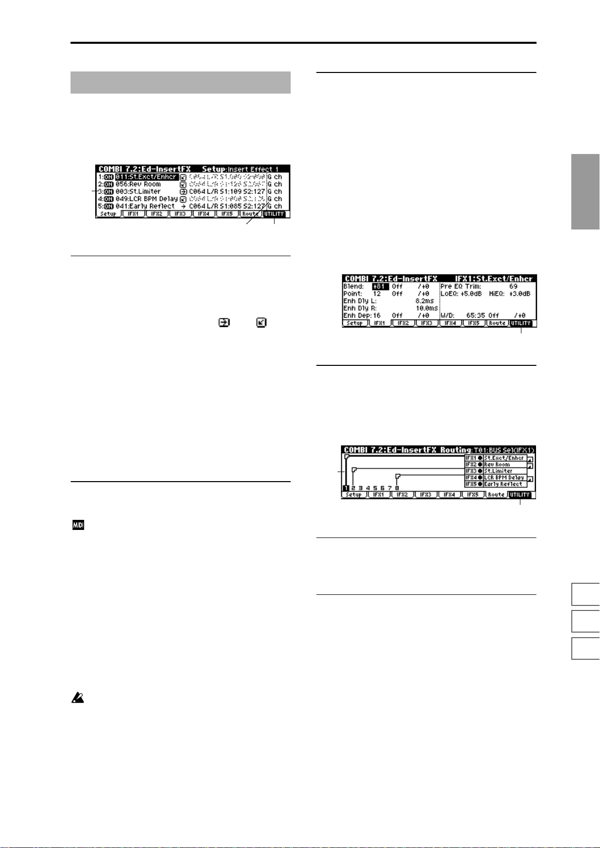
COMBI 7.2: InsertFX
7.2–1: Setup
Here you can select the type of each insert effect, turn it on/
off, and make chain settings etc.
7.2–1a
7.2–1c7.2–1b
7.2–1a: Ed-InsertFX Setup
IFX1 On/Off — IFX5 On/Off
Insert Effect 1, 5 [000...089: name]
Insert Effect 2, 3, 4 [000...102: name]
Chain [ (Off), (ON)]
Pan(CC#8) [L000...C064...R127]
BUS Select [L/R, 1, 2, 3, 4, 1/2, 3/4, Off]
S1 (Send1 (MFX1)) [000...127]
S2 (Send2 (MFX2)) [000...127]
These parameters are the same as in Program mode.
(
☞PROG 7.2–1)
However, dynamic modulation (Dmod) of the insert effects
and the “Pan (CC#8), “Send 1 (MFX1),” and “Send 2
(MFX2)” that follow the insert effects will be controlled on
the “Control Channel” (7.2-1b) MIDI channel, unlike in Program mode. The control changes used are the same as in
Program mode.
■ 7.2–1c: UTILITY
☞“Write Combination,” “Solo Selected Timbre” (1.1–1d),
“Copy Insert Effect,” “Swap Insert Ef fect” (7.1–1b), “Select
by Category” (PROG 7.2–1b)
7.2–2: IFX 1
7.2–3: IFX 2
7.2–4: IFX 3
7.2–5: IFX 4
7.2–6: IFX 5
These are the parameters for IFX 1, 2, 3, 4, and 5 that were
selected in the Setup page (
■ 7.2–2(...6)a: UTILITY
☞“Write Combination” (1.1–1d)
☞p.151).
7.2–1a
7.2–7: Route (Routing)
7.2–7a
COMBI
1.1
2.12.22.33.13.23.33.44.14.24.34.46.17.17.27.3
7.2–1b: Control Channel
Control Channel [Ch01...16, G ch, All Rt.]
Specifies the MIDI channel on which dynamic modulation (Dmod) of the insert effects and the “Pan (CC#8),
“Send 1 (MFX1),” and “Send 2 (MFX2)” that follow the
insert effects will be controlled.
The channel number of the timbre routed through this IFX
will be followed by a “*” displayed at the right of Ch01–16.
If two or timbres with different MIDI channel settings are
routed through the same IFX, this parameter specifies which
of these channels will be used to control the effect.
G ch: The global MIDI channel “MIDI Channel” (GLOBAL
2.1–1a) will be used to control the effect. Normally you will
set this to G ch.
All Rt. (All Routed): The channel of any timbre routed
through this effect can be used to control the effect. (Channels of each routed timbre will be indicated by “*”.)
If the “BUS Select” (7.1–1a) of a timbre for which a
drum program is selected is set to DKit, the MIDI channel of that timbre will be valid if any IFX1–5 is set to All
Routed, regardless of the “BUS Select” (GLOBAL 5.1–
3a) settings or the settings of the Utility “DrumKit IFX
Patch” (7.1–1b).
7.2–2b
7.2–7a: Routing Map
This shows the status of the insert effects. This shows the
same content as the 7.1: BUS, Routing page. (
■ 7.2–7b: UTILITY
☞“Write Combination,” “Solo Selected Timbre” (1.1–1d),
“Copy Insert Effect,” “Swap Insert Effect,” “DKit IFX
Patch” (7.1–1b)
☞7.1–2a)
47
Page 55

COMBI 7.3: Ed–MasterFX
☞For details on master effects, refer to p.146.
7.3–1: Setup
Here you can select the type of each master effect, turn it
on/off, and make chain and master EQ settings.
With the exception of “MFX1 Control Ch,” “MFX2 Control
Ch,” and “MEQ Control Ch,” this is the same as in Program
mode. (
☞PROG 7.3: Ed-MasterFX)
G ch: The global MIDI channel “MIDI Channel” (GLOBAL
2.1–1a) will be used for control. Normally you will set this
parameter to G ch.
■ 7.3–1e: UTILITY
☞“Write Combination,” “Solo Selected Timbre” (1.1–1d),
“Select by Category” (PROG 7.3–1d)
7.3–1a
7.3–1b
7.3–1e7.3–1c7.3–1d
7.3–1a: MasterFX Setup
MFX1 On/Off, MFX2 On/Off [Off, ON]
Master Effect 1, 2 [000...089: name]
Rtn 1, 2 (Return 1, 2) [000...127]
These are the same as in Program mode. Refer to “PROG
7.3-1: Setup.” However, the master effects will be controlled
on the “MFX 1, 2 Control Ch” MIDI channel, unlike in Program mode.
The control changes used are the same as in Program mode.
MFX 1, 2 Control Ch [Ch001...16, G ch]
Selects the MIDI channel that will control dynamic
modulation (Dmod) for the master effects.
G ch: The global MIDI channel “MIDI Channel” (GLOBAL
2.1-1a) will be used for control. Normally you will set this
parameter to G ch.
7.3–1b: MasterFX Chain
MFX Chain
Direction (Chain Direction)
[MFX1→MFX2, MFX2→MFX1]
Signal (Chain Signal) [LR Mix, L Only, R Only]
Level (Chain Level) [000...127]
These are the same as in Program mode. (☞“PROG 7.3–1:
Setup”)
Copy Master Effect
(☞PROG 7.3–1d)
Note, the MIDI control channel that is specified by “MFX1, 2
Control Ch” (7.3–1a) will not be copied.
Swap Master Effect
(☞PROG 7.3–1d)
Note, the MIDI control channel that is specified by “MFX1, 2
Control Ch” (7.3–1a) will not be swapped.
7.3–2: MFX1 (Master Effect1)
7.3–3: MFX2 (Master Effect2)
Here you can set the parameters for the “Master Effect1”
and “Master Effect2” effects that were selected in the Setup
page (
☞p.151).
7.3–2a
■ 7.3–2(3)a: UTILITY
☞“Write Combination” (1.1–1d)
7.3–4: MEQ (Master EQ)
The master EQ is a three-band stereo EQ. It is located immediately before the AUDIO OUTPUT (MAIN OUT) L/
MONO and R from the L/R bus, and adjusts the overall
tonal character of the sound (
☞p.203).
7.3–1c: Master EQ Gain [dB]
Low [–18.0...+18.0]
Mid [–18.0...+18.0]
High [–18.0...+18.0]
These are the same as in Program mode. (☞“PROG 7.3–1:
Setup”)
7.3–1d: MEQ Ctrl
MEQ Ctrl (MEQ Control Ch) [Ch01...16, G ch]
Selects the MIDI channel that will control dynamic
modulation (Dmod) for the master EQ.
48
7.3–4a
■ 7.3–4a: UTILITY
☞“Write Combination” (1.1–1d)
Page 56

3. Multi mode
In Multi mode, the TRITON-Rack functions as a multi-timbral MIDI tone generator that can receive and play multiple
channel of MIDI messages from an external MIDI sequencer .
A “Multi” has sixteen tracks for playing back musical data.
Y ou can assign a separate program and MIDI channel etc. to
each track, so that multiple programs can sound simultaneously.
In Multi mode you can also play patterns and use RPPR
(Realtime Pattern Play/Recording) or the arpeggiator, so
that these functions can be played in synchronization with
an external MIDI sequencer.
As patterns, the TRITON-Rack provides 150 preset patterns
that are ideal for drum tracks, and 100 user patterns that you
can record and edit or even use for recording with the arpeggiator.
When you execute the Sampling mode command “Time
Slice” (SMPL 3.1–2e), a pattern will be created for the
divided samples and this pattern will be assigned to
RPPR automatically.
By time-slicing two or more rhythm loop samples of
differing tempo and assigning them to RPPR, you can
match the tempo of the rhythm loop samples without
changing their pitch. Then you can use the keyboard of
a connected MIDI instrument to turn these rhythm loop
samples on/off, and use the REALTIME CONTROLS
[TEMPO] knob in C-mode to adjust the tempo in realtime.
When you turn off the power, the settings and user pattern data will be erased. If there is data that you wish to
keep, you must save it on a floppy disk, external SCSI
device, or data filer before turning off the power. Then
after you turn the power on again, you will need to
load the data that you saved. (
☞p.133, 113, BG p.40)
MULTI PAGE MENU
For details on how to select pages in Multi mode, refer to
p.1.
Play 1.1: Play Select multis. Select a program for each
Ctrl 2.2: Controller Controller settings. (
MOSS 2.3: MOSS Displayed if the separately sold EXB-MOSS
Prm1 3.1: Param1 MIDI, voice mode, and pitch settings for each
Prm2 3.2: Param2 Delay and scale settings for each track.
KeyZ 3.3: Key Zone Key zone settings for each track. (
VelZ 3.4: Vel Zone Velocity zone settings for each track. (
MIDI1 4.1: MIDI
Filter1
MIDI2 4.2: MIDI
Filter2
MIDI3 4.3: MIDI
Filter3
MIDI4 4.4: MIDI
Filter4
RPPR 5.1: RPPR Pattern recording and editing. RPPR settings.
Arp 6.1: Arp. Arpeggiator settings. (
BUS 7.1: BUS Set BUS and master effect send level for
IFX 7.2: InsertFX Insert effect routing, selection, and settings.
MFX 7.3: MasterFX Master effect selection and settings. Master
track, and make pan and level settings.
☞p.50)
(
☞p.53)
option is installed. Make EXB-MOSS parameter settings. (
track. (
☞p.56)
(
MIDI message transmission/reception filter
settings for each track: Prog Change, After
Touch etc. (
Filter settings: JS, Ribbon Ctrl etc. (
Filter settings: Realtime Control Knob
☞p.60)
(
Filter settings: SW, Other Ctrl Change
☞p.60)
(
☞p.61)
(
each track.(
(
☞p.70)
EQ settings. (
☞p.54)
☞p.56)
☞p.56)
☞p.57)
☞p.58)
☞p.59)
☞p.67)
☞p.69)
☞p.71)
MULTI
1.1
2.22.33.13.23.33.44.14.24.34.45.16.17.17.27.3
49
Page 57
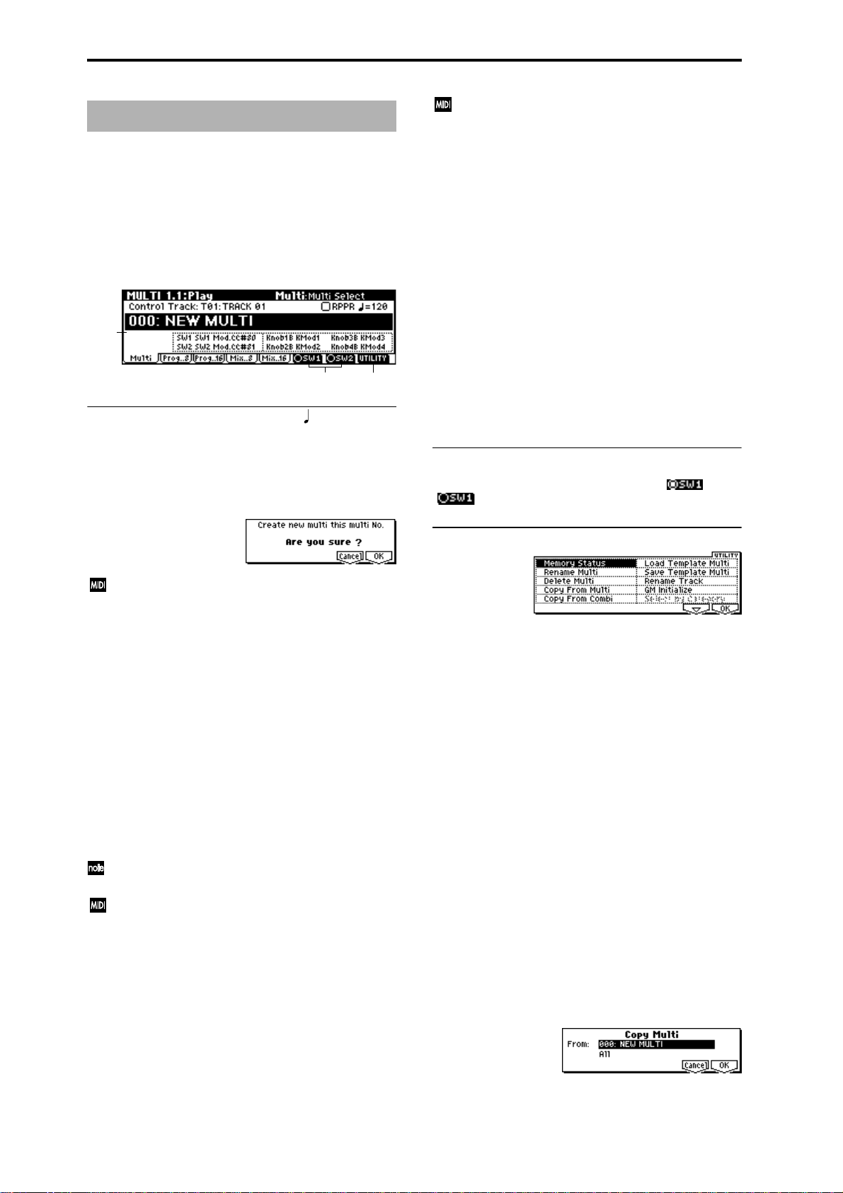
MULTI 1.1: Play
Here you can select multis, and make basic settings such as
selecting the program used by each track.
This is controlled on the MIDI channel of the track
selected by “Control Track.” If you wish to use the
RPPR function, set the MIDI channel of the external
MIDI device to the same MIDI channel as the channel
of the “Control Track,” and play the patterns by sending the note numbers that correspond to the pattern
assigned to each key.
1.1–1: Multi
Selects a multi, and the track that will be controlled by the
REALTIME CONTROLS. Here you can also turn RPPR on/
off.
1.1–1a
1.1–1b
1.1–1a: Multi Select, Control Track, , RPPR
Multi Select [000…199: name]
Selects the multi that you wish to use.
To create a new multi, use numeric keys [0]–[9] to specify a
new multi number, and pr ess the [ENTER] key. A dialog box
will appear. Press the [F8] (“OK”) key to create a new multi.
If “MIDI Clock” (GLOBAL 2.1–1a) is set to Internal, a
song select message will be transmitted when you
change multis. If it is set to External, the multi will
change when you transmit a song select message from
the specified source. When the multi number changes,
tracks whose “Status” (3.1–1a/2a) is EXT, EX2 or BTH
will transmit bank select, program change, volume,
pan, portamento, send 1 and 2, post IFX pan, and post
IFX send 1 and 2 messages on the MIDI channel of that
track.
Control Track [T01…T16: name]
Selects the track that will be controlled by the B mode functions of the TRITON-Rack’s REALTIME CONTROLS knobs
[1]–[4], “SW1,” “SW2,” and RPPR.
In the 5.1 RPPR page, “Control Track” is used as the track
that will record/play pattern data.
This parameter can also be set from the 5.1 RPPR, Pattern,
RPPR Setup pages.
T rack names can be specified in Utility “Rename Track”
(1.1–1c).
When you operate the controllers of the TRITON-Rack,
the corresponding controller message will be transmitted on the MIDI channel specified for that track (if “Sta-
tus” 3.1–1a/2a is EXT, EX2 or BTH).
RPPR On/Off [Off, On]
This turns the RPPR (Realtime Pattern Play/Recording)
function on/off. RPPR is a function that lets you assign user
patterns or preset patterns to each key of a multi, so that the
patterns can be played simply by pressing a key on a connected MIDI instrument. The patterns played can be
recorded on an external sequencer etc.
On (Checked):The RPPR function will be on. If a pattern is
assigned to each key in the 5.1: RPPR, RPPR Setup page,
pressing that key will play the assigned pattern.
1.1–1c
(Tempo) [040…240, EXT]
Specifies the tempo of the RPPR (patterns) and arpeggiator.
040...240: This will be displayed if “MIDI Clock” (GLOBAL
2.1–1a) is Internal. The tempo you specify here will be used.
EXT: This will be displayed if “MIDI Clock” is External. The
tempo of the TRITON-Rack will synchronize to the MIDI
clock messages received from an external sequencer etc.
This parameter can also be set from the 5.1: RPPR, RPPR
Setup page.
Multi Information
This displays the functions assigned to “SW1,” “SW2,” and
REALTIME CONTROLS B mode [ASSIGNABLE 1–4] knobs
for the selected multi.
■ 1.1–1b: SW1, SW2
This turns the functions of SW1 and SW2 on ( ) or off
( ). (
■ 1.1–1c: UTILITY
For details on how to select the desired utility function, refer
to “PROG 1.1–1d: UTILITY.”
☞2.2: Controller)
Memory Status
Selects “Memory Status,” access the dialog box and view the
remaining amount of memory for patterns etc.
Rename Multi
Selects “Rename Multi,” access the dialog box and rename
the selected multi. Up to sixteen characters can be input.
☞BG p.38)
(
Delete Multi
This command deletes the currently selected multi.
1 Select “Delete Multi” to access the dialog box.
2 If you wish to execute the Delete Multi command, press
the [F8] (“OK”) key. To cancel, press the [F7] (“Cancel”)
key. When you execute this command, setting data, and
patterns etc. of the currently selected multi will be
erased, and the memory area allocated to that multi will
be freed.
Copy From Multi
This command copies all setting data and pattern data from
the specified multi to the currently selected multi.
1 Select “Copy From Multi” to access the dialog box.
2 In “From,” specify the copy source multi number.
50
Page 58

3 Select the data that you wish to copy.
All: will copy all pattern data and musical data.
“Without Patterns”: Multi settings other than pattern
data and RPPR settings will be copied.
4 To execute the Copy Multi operation, press the [F8]
(“OK”) key. To cancel without executing press the [F7]
(“Cancel”) key. If you execute “All,” all settings and pattern data of the currently selected multi will be deleted
and replaced by the copy source data. If you execute
“Without Patterns,” all setting data other than the pattern data and RPPR settings of the currently selected
multi will be deleted and replaced by the copy source
data.
Copy From Combi (Copy from Combination)
This command copies the parameters of the specified combination to the currently selected multi.
1 Select “Copy From Combi” to access the dialog box.
Rename Track
Selects “Rename Track,” access the dialog box and rename
the selected multi. Up to sixteen characters can be input.
(
☞BG p.38)
GM Initialize
This command resets each track to settings appropriate for
GM. (
☞See the table at the bottom of the next page.)
When a GM System On message is received from an
external device in Multi mode, the TRITON-Rack will
be reset to GM settings in the same way as when this
command is executed. (However in these cases, the various 7.3: MasterFx parameters will not be reset.)
1.1–2: Prog..8 (Track Program T01...08)
1.1–3: Prog..16 (Track Program T09...16)
Specifies the program used by each track.
MULTI
2 In “Combi,” select the copy source destination.
3 If you check “with Effects,” the insertion effect, master
effect, and master EQ settings will also be copied.
4 In “To,” select the copy destination tracks (1–8 or 9–16).
5 To execute the Copy From Combi command, press the
[F8] (“OK”) key. To cancel, press the [F7] (“Cancel”) key.
Be aware that when you execute this command, the setting data of the currently selected multi will be erased,
and overwritten by the data of the selected combination.
Load Template Multi
This command loads a template multi into the multi mode.
The TRITON-Rack contains sixteen preset template multis
(P00–15) with program and effect settings appropriate for
various styles of music. You can also create sixteen user tem-
plate multis (U00–15) with the programs, track parameters,
and effects etc. that you use frequently. (
Multi”)
1 Select “Load Template Multi” to access the dialog box.
2 In “From,” specify the template multi that you wish to
load.
3 To load the template multi, press the [F8] (“OK”) key. To
cancel, press the [F7] (“Cancel”) key. When you execute
the command, multi setting data other than pattern data
and RPPR will be copied.
☞“Save Template
Save Template Multi (Save as User Template Multi)
This command saves the program selections, track parameters, and effect settings etc. of the multi as a user template
multi U00–15.
1 Select “Save Template Multi” to access the dialog box.
1.1–2a
1.1–2b
1.1–2c
1.1–2d
1.1–2(3)a: Track Number & Category
Track Number & Category
This shows the track number and the abbreviated name of
the program category.
1.1–2(3)b: Program Select
Program Select
[I-A...F/E-A...H 000...127, G...g 001...128: name]
Selects the program used by each track.
If the “Status” (3.1–1a/2a) is EX2, a “–” will be displayed
before the program number.
By holding down the [TIMBRE/TRACK] key and
pressing a [F1](1/9)–[F8](8/16) key you can move to
the corresponding track “T1”–”T16.”
The program bank can also be selected directly by using
the [A]–[H] keys and the [BANK] key.
You can also use the “Select by Category” utility to
select programs by category.
If the “Status” (3.1–1a/2a) is either INT or BTH, programs can be selected by receiving MIDI program
change messages. Also, when the multi is changed,
tracks whose “Status” is EXT, EX2 or BTH will transmit
the bank and program numbers via MIDI. Tracks
whose “Status” is EX2 will transmit the bank number
that was selected in the “Bank(EX2) LSB,” “Bank(EX2)
MSB” (3.1–1a).
1.1
2.22.33.13.23.33.44.14.24.34.45.16.17.17.27.3
2 In “To,” specify the user template multi (U00–15) in
which the data will be saved.
3 To save the template multi, press the [F8] (“OK”) key. To
cancel, press the [F7] (“Cancel”) key. Be aware that when
you execute this command, all setting data of the save
destination User Template Multi will be erased and
rewritten.
51
Page 59

The lower line shows part of the program name used by the
track. For GM2 variation banks or the GM2 drums bank, the
variation bank (1)–(9) or drums bank (d) will be shown.
1.1–2(3)c: Track Infomation
Track Infomation
This shows the currently selected track, program bank,
number, name, and MIDI channel.
1.1–4: Mix..8 (Mixer T01...08)
1.1–5: Mix..16 (Mixer T09...16)
Here you can set the pan and volume of each track.
1.1–4a
■ 1.1–2(3)d: UTILITY
☞“Memory Status,” “Rename Multi,” “Delete Multi,”
“Copy From Multi,” “Copy From Combi,” “Load Template Multi,” “Save Template Multi,” “Rename
Track,”“GM Initialize”(1.1–1c)
Select by Category
You can select the program for each track by category. This
command can be selected when a Program page (Prog..8,
Prog..16) is displayed. (
☞PROG 1.1–1a)
1.1–4b
1.1–4(5)a: Pan, Volume
Pan [RND, L001...C064...R127]
Sets the pan of tracks 1–16.
L001...C064...R127: A setting of L001 is far left, and R127 is
far right. A setting of C064 will reproduce the pan setting of
the oscillator in Program mode.
OSC1
Left
Left
OSC1
Left
Left
Center
Center
Center
Center
OSC2
OSC1: Amp1 Pan=L001
OSC2: Amp2 Pan=R127
Right
Pan (CC#10)
C064
L032
L001
R096
R127
Right
OSC2
OSC1: Amp1 Pan=C064
OSC2: Amp2 Pan=C064
Right
Pan (CC#10)
C064
L032
L001
R096
R127
Right
OSC1: Amp1 Pan=L032
Left
Center
Left
Center
OSC2: Amp2 Pan=R096
Right
Pan (CC#10)
C064
L032
L001
R096
R127
Right
GM Initialize Parameters
Parameter Track1–9, 11–16 Track10
1.1 Program Select G001:Acoustic Piano g(d)001:STANDARD Kit
Pan C064 C064
Volume 100 100
3.1 Status ––The setting remains unchanged
3.2 Use Program’s Scale ––The setting remains unchanged
6.1 Arpeggiator Assign ––The setting remains unchanged
Other Arpeggiator parameters ––The setting remains unchanged
7.1 IFX/Indiv.Out BUS Select L/R DKit
Send1(MFX1) 0 0
Send2(MFX2) 40 40
7.2 IFX1–5 ––The setting remains unchanged
Pan(CC#8) ––The setting remains unchanged
BUS Select ––The setting remains unchanged
Send1 ––The setting remains unchanged
Send2 ––The setting remains unchanged
Other Insert Effect parameters ––The setting remains unchanged
7.3 MFX1 ––016: St.Chorus
MFX2 ––053: Rev Smth. Hall
Return1 ––127
Return2 ––050
Other Master Effect and Master EQ parameters – – Default settings
52
Page 60
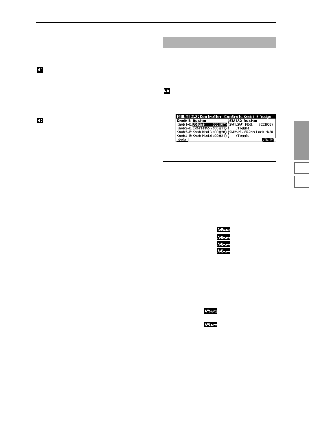
If a mono-type insertion effect is inserted, this setting will be
ignored. In this case, the 7.2: Insert FX, Setup page “Pan
(CC#8)” setting will adjust the pan of the sound following
the insertion effect.
RND: The sound will be panned randomly at each note-on.
If “Status” (3.1–1a/2a) is INT or BTH, CC#10 Panpot
can be received to control the panning. When receiving
CC#10, a value of 0 or 1 is far left, 64 is center, and 127 is
far right. When you change the multi, tracks whose
“Status” is EXT, EX2 or BTH will transmit the pan you
specify here as a MIDI message (except for RND).
Volume [000...127]
Sets the volume of tracks 1–16.
When “Status” (3.1–1a/2a) is INT or BTH, CC#7 Volume can be received to control the volume. The volume
of a track is determined by multiplying the MIDI Volume (CC#7) and Expression (CC#11) values. When you
change the multi, tracks whose “Status” is EXT, EX2 or
BTH will transmit the volume you specify here as a
MIDI Volume message.
MULTI 2.2: Controller
2.2–1: Ctrls (Controllers)
Selects the B-mode functions of REALTIME CONTROLS
knobs [1]–[4] and the functions of “SW1” and “SW2” in
Multi mode.
When you operate these controllers on the MIDI channel of the “Control Track,” the MIDI messages assigned
here will be transmitted (if “Status” 3.1–1a/2a is EXT,
EX2, or BTH).
2.2–1a
2.2–1c2.2–1b
MULTI
■ 1.1–4(5)b: UTILITY
☞“Memory Status,” “Rename Multi,” “Delete Multi,”
“Copy From Multi,” “Copy From Combi,” “Load Template Multi,” “Save Template Multi,” “Rename Track,”
“GM Initialize” (1.1–1c)
2.2–1a: Knob B Assign
Here you can set the B-mode functions (mainly various control changes) that the REALTIME CONTROLS knobs [1]–[4]
will have (
When the REALTIME CONTROLS are in B-mode, the functions you specify here will be controlled on the track and
MIDI channel of the “Control Track” (1.1–1a) when you
operate knobs [1]–[4].
The functions you specify here will operate when you rotate
the REALTIME CONTROLS knobs [1]–[4] in B-mode.
☞p.214 “Realtime Control Knobs B Assign List”).
Knob1–B (Knob1–B Assign) [Off, ..., MIDI CC#95]
Knob2–B (Knob2–B Assign) [Off, ..., MIDI CC#95]
Knob3–B (Knob3–B Assign) [Off, ..., MIDI CC#95]
Knob4–B (Knob4–B Assign) [Off, ..., MIDI CC#95]
2.2–1b: Switch1/2 Assign
Assigns functions to the “SW1” and “SW2” (☞p.213 “SW1,
SW2 Assign List”).
Since the “SW1” and “SW2” function assignments of the
program assigned to each track are ignored when the program is used in a multi, you must make new assignments
here for the multi.
SW1 (SW1 Assign) [Off, ..., AfterT Lock :N/A]
SW1 Mode [Toggle, Momentary]
SW2 (SW2 Assign) [Off, ..., AfterT Lock :N/A]
SW2 Mode [Toggle, Momentary]
(☞PROG 2.2–1b)
1.1
2.22.33.13.23.33.44.14.24.34.45.16.17.17.27.3
■ 2.2–1c: UTILITY
☞“Memory Status,” “Rename Multi,” “Delete Multi,”
“Copy From Multi,” “Copy From Combi,” “Load Template Multi,” “Save Template Multi” (1.1–1c)
53
Page 61
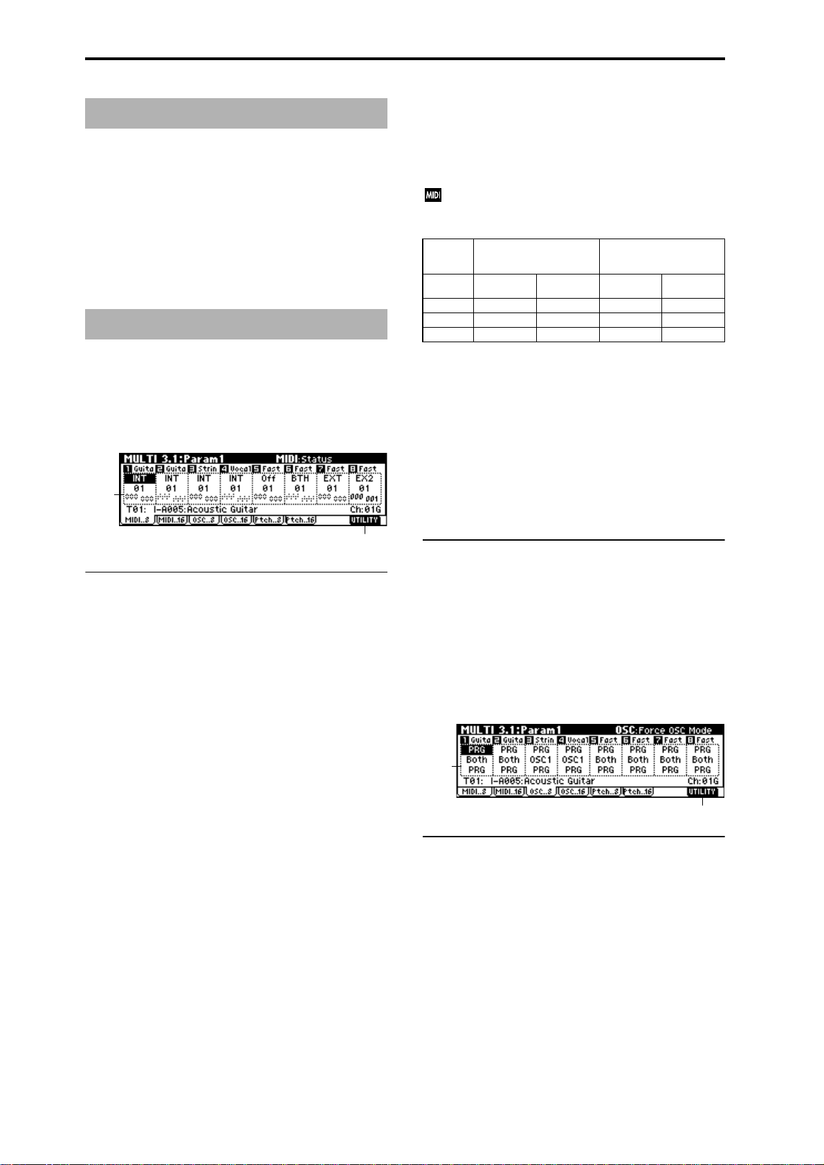
MULTI 2.3: MOSS
2.3–1: MOS..8 (MOSS T01–08)
2.3–2: MOS..16 (MOSS T09–16)
This page is displayed when the separately sold EXB-MOSS
option has been installed.
(
☞EXB-MOSS owner’s manual & p.251 “EXB-MOSS
option”)
MULTI 3.1: Param1 (Parameter1)
3.1–1: MIDI..8 (MIDI T01–08)
3.1–2: MIDI..16 (MIDI T09–16)
Here you can make MIDI-related settings for each track.
3.1–1a
send 1, 2, post IFX pan, and post IFX send 1, 2 MIDI messages.
EX2: “Bank Select” will be enabled. Instead of the I-A–E-H
bank numbers that can be selected on the TRITON-Rack, the
bank number you specify here will be transmitted. In other
respects this is the same as EXT.
MIDI data is transmitted and received on the MIDI
channel that is specified separately for each track by
“MIDI Channel.”
Data from RPPR or Arp.
Operations on the TRIT ON-
Status Internal tone
INT
EXT, EX2 ×
BTH
Rack
generator
●
●●●
MIDI OUT Internal tone
×
●
Received data
generator
●
× —
MIDI OUT
—
—
MIDI Channel [01…16]
Specifies the MIDI channel that the track will use to transmit
and receive note data. Tracks set to INT which have the
same MIDI channel will sound and be controlled identically
when they receive MIDI data or RPPR data.
Bank(EX2) MSB [000...127]
Bank(EX2) LSB [000...127]
When “Status” is set to EX2, this sets the bank number that
will be transmitted. When “Status” is other than EX2, this
setting has no effect.
3.1–1b
3.1–1(2)a: Status, MIDI Channel, Bank(EX2) MSB/LSB
Status [INT, Off, BTH, EXT, EX2]
This sets the status of MIDI and the internal tone generator
for each track.
INT: The tone generator will sound in response to incoming
MIDI messages from a connected external MIDI device.
MIDI messages will not be transmitted. If RPPR or the
arpeggiator are assigned to a track that is set to INT, only
the TRITON-Rack will sound; MIDI data will not be transmitted to an external device (i.e., the external MIDI device
will not sound). If the TRITON-Rack’s controllers are operated on the track specified as the “Control Track” (1.1–1a),
only the TRITON-Rack will be controlled, and MIDI messages will not be transmitted.
Off: The program will not sound, nor will MIDI data be
transmitted.
BTH: The operations of both INT and EXT will be performed. If RPPR or the arpeggiator is specified for a track set
to BTH, the TRITON-Rack will sound and MIDI messages
will also be transmitted. If the TRITON-Rack’s controllers
are operated on the track specified as the “Control Track”
(1.1–1a), the TRITON-Rack will be controlled and the same
data will also be transmitted via MIDI.
EXT: MIDI messages will be transmitted without sounding
the internal program. If RPPR or the arpeggiator are
assigned to a track that is set to EXT, MIDI data will be
transmitted to an external device, but the tone generator of
the TRITON-Rack will not sound. If the TRITON-Rack’s
controllers are operated on the track specified as the “Control Track” (1.1–1a), MIDI messages will also be transmitted
to control the external device, but the TRITON-Rack itself
will not be controlled.
When you switch the multi, tracks that are set to EXT will
transmit program change, volume, panpot, portamento,
■ 3.1–1(2)b: UTILITY
☞“Memory Status,” “Rename Multi,” “Delete Multi,”
“Copy From Multi,” “Copy From Combi,” “Load Template Multi,” “Save Template Multi” (1.1–1c)
3.1–3: OSC..8 (OSC T01–08)
3.1–4: OSC..16 (OSC T09–16)
Indicates settings for each track.
3.1–3a
3.1–3b
3.1–3(4)a: Force OSC Mode, OSC Select,
Portamento
Force OSC Mode [PRG, Poly, Mono, LGT]
Selects the “Mode (Voice Assign Mode)” (PROG 2.1–1b) of
the program selected for each track 1–8, 9–16.
(
☞COMBI 3.1–2a)
OSC Select [Both, OSC1, OSC2]
Specifies the “Mode (Oscillator Mode)” (PROG 2.1–1a) of
the program selected for each track 1–8, 9–16. If the “Mode
(Oscillator Mode)” is Double, you can use this setting to
make only one or the other oscillator sound (
2a).
☞COMBI 3.1–
54
Page 62

Portamento [PRG, Off, 001...127]
Specifies the portamento effect for each track 1–8, 9–16.
☞COMBI 3.1–2a)
(
When the track whose “Status” (3.1–1a/2a) is INT or
BTH, MIDI control change CC#05 (Portamento Time)
and CC#65 (Portamento Switch) can be received to control this and change the setting. (If the setting is PRG,
CC#05 Portamento Time will not be received.)
Tracks whose “Status” is BTH, EXT, or EX2 will transmit these settings via MIDI when you change this setting or when you change multis.
If this is Off, CC#65 with a value of 0 will be transmitted. If this is 001–127, a CC#65 of 127 and CC#05 of
001–127 will be transmitted.
If this is set to PRG, nothing will be transmitted.
This data is transmitted on the MIDI channel specified
for each track by “MIDI Channel” (3.1–1a/2a).
to control and change the “Detune” setting. The range
of control will be ±1 octave when Coarse Tune and
Fine Tune are added. These messages will be received
on the MIDI channel that is specified for each track by
“MIDI Channel” (3.1–1a/2a).
Bend Range [PRG, –24...+24]
Specifies the range of pitch change that will occur when the
MIDI Pitch Bend Change message is received.
PRG: The pitch range specified by the program will be used.
–24–+24: Regardless of the setting of the program, pitch
bending will use the range you specify here.
This setting can be controlled and changed by received
MIDI RPN Pitch Bend Range messages. (These messages will not be received if the setting is PRG.) This is
controlled on the MIDI channel specified for each track
by “MIDI Channel” (3.1–1a/2a).
■ 3.1–3(4)b: UTILITY
☞“Memory Status,” “Rename Multi,” “Delete Multi,”
“Copy From Multi,” “Copy From Combi,” “Load Template Multi,” “Save Template Multi” (1.1–1c)
3.1–5: Ptch..8 (Pitch T01–08)
3.1–6: Ptch..16 (Pitch T09–16)
Here you can make pitch-related settings for each track.
3.1–5a
3.1–5b
3.1–5(6)a: Transpose, Detune, Bend Range
Transpose [–24...+24]
Adjusts the pitch of each track in semitone steps.
12 steps are one octave.
Detune (BPM Adj.) [–1200... +1200]
Adjusts the pitch of each track in one-cent steps from the
normal pitch.
0: Normal pitch.
You can use the Utility “Detune BPM Adj.” (3.1–5/6b)
to make a calculation in BPM units and set Detune
automatically.
“Transpose” and “Detune” settings do not affect the
note data that is transmitted via MIDI. “Transpose” and
“Detune” are controlled by received MIDI RPN messages. The “Mode (Oscillator Mode)” (PROG 2.1–1a) of
the programs selected for tracks 1–16 will be controlled
as follows.
• If “Mode (Oscillator Mode)” is Single or Double,
MIDI RPN Coarse Tune messages can be received to
control and change the “Transpose” setting, and Fine
Tune messages to control and change the “Detune”
setting.
• If “Mode (Oscillator Mode)” is Drums, MIDI RPN
Coarse Tune and Fine Tune messages can be received
■ 3.1–5(6)b: UTILITY
☞“Memory Status,” “Rename Multi,” “Delete Multi,”
“Copy From Multi,” “Copy From Combi,” “Load Template Multi,” “Save Template Multi” (1.1–1c)
For details on how to select the desired utility function, refer
to “PROG 1.1–1d: UTILITY.”
Detune BPM Adj. (Detune BPM Adjust)
If a drum program uses a multisample or sample of a phrase
or rhythm loop etc. that was created in Sampling mode (or
loaded in Disk mode) to match a specific BPM, you can use
this utility command to modify its BPM. “Detune BPM Adj.”
changes the BPM of a phrase or rhythm by modifying its
pitch.
This command is available for a track if the track “Detune”
parameter is selected. When you execute this command, the
selected “Detune” value will be set automatically (
2.1–2c, 2.1–3, GLOBAL 5.1–1b, 5.1–2).
For the procedure, refer to “Detune BPM Adj.” (COMBI 3.1–
3b).
☞PROG
MULTI
1.1
2.22.33.13.23.33.44.14.24.34.45.16.17.17.27.3
55
Page 63
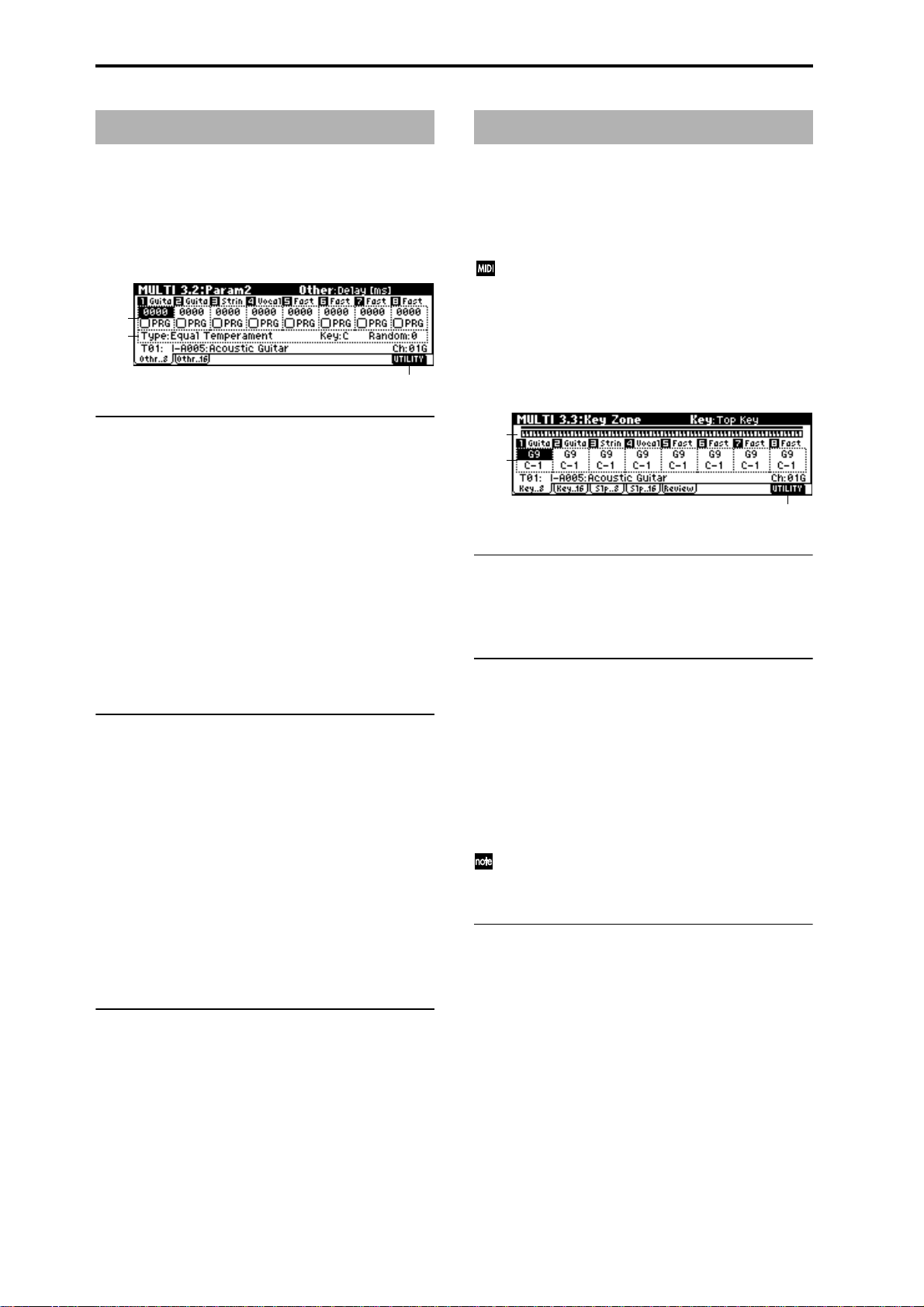
MULTI 3.2: Param2 (Parameter2)
3.2–1: Othr..8 (Other T01–08)
3.2–2: Othr..16 (Other T09–16)
For each track, specify the delay time from note-on until the
sound is heard, and select the scale.
3.2–1a
3.2–1b
3.2–1c
MULTI 3.3: Key Zone
Here you can specify the range of keys that will be sounded
by each track.
T op/Bottom Key settings specify the range of notes that will
be sounded by tracks 1–8, 9–16, and Top/Bottom Slope settings specify the range from the top/bottom key until the
original volume is reached.
This setting does not affect MIDI transmission. All note
data produced by RPPR and the arpeggiator will be
transmitted.
3.3–1: Key..8 (Key Zone T01–08)
3.3–2: Key..16 (Key Zone T09–16)
3.2–1(2)a: Delay [ms] , Use Prog’s Scale
Delay [ms] [0000...5000, KeyOff]
Specifies a delay time from when a track receives a note-on
until it actually sounds.
KeyOff: The sound will begin when note-off occurs. In this
case, the sound will continue indefinitely unless the amp EG
Sustain Level of the program is other than 0. This setting is
useful for simulating harpsichord sounds.
Normally you will leave this at 0.
Use Prog’s Scale [Off, On]
Each track can use the scale that is specified for the program
by “Scale” (PROG 2.1–1c).
On (Checked): The scale of the program will be used.
Off (Unchecked): The scale specified by “Type (Multi’s
Scale)” (3.2–1b/2b) will be used.
3.2–1(2)b: Scale
Specifies the scale that will be used for the multi.
Type (Multi’s Scale)
[Equal Temperament...User Octave15]
Selects the type of scale.
☞“Type (Scale Type)” (PROG 2.1–1c)
Key [C…B]
Selects the tonic key of the selected scale.
☞“Key” (PROG 2.1–1c)
3.3–1a
3.3–1b
3.3–1c
3.3–1(2)a: Key Zone Map (1)
This shows the range of note data that will sound the currently selected track. The note range that will be sounded is
shown as a line, and the slope portion is grayed.
3.3–1(2)b: Top Key, Bottom Key
Top Key [C–1...G9]
Specifies the top key (upper limit) that will be sounded by
each track 1–8, 9–16.
Bottom Key [C–1...G9]
Specifies the bottom key (lower limit) that will be sounded
by each track 1–8, 9–16.
For a diagram of Key and Slope parameters, refer to
“COMBI 3.3: Ed-Key Zone.”
The value of these parameters can also be set by holding down the [ENTER] key and playing a note on a connected MIDI instrument.
Random [0…7]
As this value is increased, an increasingly random deviation will be added to the pitch at each note-on.
☞“Random” (PROG 2.1–1c)
■ 3.2–1(2)c: UTILITY
☞“Memory Status,” “Rename Multi,” “Delete Multi,”
“Copy From Multi,” “Copy From Combi,” “Load Template Multi,” “Save Template Multi” (1.1–1c)
56
■ 3.3–1(2)c: UTILITY
☞“Memory Status,” “Rename Multi,” “Delete Multi,”
“Copy From Multi,” “Copy From Combi,” “Load Template Multim,” “Save Template Multi” (1.1–1c)
Page 64

3.3–3: Slp..8 (Key Slope T01–08)
3.3–4: Slp..16 (Key Slope T09–16)
3.3–3a
3.3–3b
3.3–3(4)a: Top Slope, Bottom Slope
Top Slope [00...72]
Specifies the key range (12 is one octave) from the top key of
track 1–8, 9–16 until the original volume is reached.
MULTI 3.4: Vel Zone (Velocity Zone)
Specifies the range of velocities that will sound each track.
Set the Top/Bottom Velocity parameters to set the range of
velocities that will sound tracks 1–8 and 9–16, and set the
Top/Bottom Slope parameters to specify the range over
which the volume will change.
These settings do not affect MIDI transmission. All note
data produced by RPPR and the arpeggiator will be
transmitted.
3.4–1: Vel..8 (Velocity Zone T01–08)
3.4–2: Vel..16 (Velocity Zone T09–16)
Bottom Slope [00...72]
Specifies the key range (12 is one octave) from the bottom
key of track 1–8, 9–16 until the original volume is reached.
■ 3.3–3(4)b: UTILITY
☞“Memory Status,” “Rename Multi,” “Delete Multi,”
“Copy From Multi,” “Copy From Combi,” “Load Template Multi,” “Save Template Multi” (1.1–1c)
3.3–5: Review
3.3–5a
3.3–5b
3.3–5a: Key Zone Map (All)
T1...T16
This shows the range of note data that will be sounded by
tracks 1–16. The note range that will be sounded is shown as
a line, and the slope portion is grayed.
3.4–1a
3.4–1b
3.4–1c
3.4–1(2)a: Velocity Zone Map (1)
This shows the range of velocities that will sound the currently selected track. The velocity range that will be
sounded is shown as a line, and the slope portion is grayed.
3.4–1(2)b: Top Velocity, Bottom Velocity
Top Velocity [1…127]
Specifies the maximum velocity that will be sounded by
each track 1–8, 9–16.
Bottom Velocity [1…127]
Specifies the minimum velocity that will be sounded by each
track 1–8, 9–16.
The value of these parameters can also be set by holding down the [ENTER] key and playing a note on a connected MIDI instrument.
MULTI
1.1
2.22.33.13.23.33.44.14.24.34.45.16.17.17.27.3
■ 3.3–5b: UTILITY
☞“Memory Status,” “Rename Multi,” “Delete Multi,”
“Copy From Multi,” “Copy From Combi,” “Load Template Multi,” “Save Template Multi” (1.1–1c)
■ 3.4–1(2)c: UTILITY
☞“Memory Status,” “Rename Multi,” “Delete Multi,”
“Copy From Multi,” “Copy From Combi,” “Load Template Multi,” “Save Template Multi” (1.1–1c)
57
Page 65

3.4–3: Slp..8 (Velocity Slope T01–08)
3.4–4: Slp..16 (Velocity Slope T09–16)
3.4–3a
3.4–3b
3.4–3(4)a: Top Slope, Bottom Slope
Top Slope [0…120]
Specifies the range of values over which the volume will be
adjusted from the top velocity until the original volume is
reached.
Bottom Slope [0…120]
Specifies the range of values over which the volume will be
adjusted from the bottom velocity until the original volume
is reached.
For a diagram of these parameters, refer to “COMBI 3.4: EdVel Zone.”
■ 3.4–3(4)b: UTILITY
☞“Memory Status,” “Rename Multi,” “Delete Multi,”
“Copy From Multi,” “Copy From Combi,” “Load Template Multi,” “Save Template Multi” (1.1–1c)
MULTI 4.1: MIDI Filter1
Here you can select whether or not to apply filtering to the
MIDI data received by tracks 1–16. For example, even if two
tracks are receiving the same MIDI channels, one can be
made to respond to damper pedal activity while the other
does not.
These settings affect the MIDI messages that are transmitted when you adjust program, pan, volume, portamento and send 1/2 parameters of a track whose
“Status” (3.1–1a/2a) is set to BTH, EXT, or EX2.
On (Checked): Reception of MIDI data is enabled. Tracks
whose “Status” (3.1–1a/2a) is INT or BTH will receive MIDI
messages whose channel matches and whose types are
checked. The types of effect that are checked will be applied
to the program of each track when the TRITON-Rack’s controllers are operated or when MIDI data is received. (The
effect dynamic modulation function is not affected by these
settings.) Settings that regulate MIDI transmission/reception of the TRITON-Rack itself are made in “MIDI Filter”
(GLOBAL 2.1–1b).
If MIDI control changes have been assigned as the function
of the REALTIME CONTROLS knobs or of “SW1” and
“SW2,” the MIDI filter for these controllers (MIDI Filter 3, 4)
will affect these control changes. However if these are the
same as the control changes of MIDI Filter 1, 2, the MIDI Filter 1, 2 settings will take priority. Furthermore, if the same
control change has been assigned to two or more controllers,
checking any one of the MIDI Filter 3 or 4 parameters will
cause the setting to apply to that control change.
Off (Unchecked): Reception of MIDI data is disabled.
3.4–5: Review
3.4–5a
3.4–5b
3.4–5a: Velocity Zone Map (All)
T1...T16
This shows the range of velocity that will be sounded by
tracks 1–16. The note range that will be sounded is shown as
a line, and the slope portion is grayed.
■ 3.4–5b: UTILITY
☞“Memory Status,” “Rename Multi,” “Delete Multi,”
“Copy From Multi,” “Copy From Combi,” “Load Template Multi,” “Save Template Multi” (1.1–1c)
4.1–1: M1–1..8 (MIDI Filter1–1 T01–08)
4.1–2: 1–1..16 (MIDI Filter1–1 T09–16)
4.1–1a
4.1–1b
4.1–1(2)a: Program Change, After Touch
Program Change [Off, On]
Specifies whether or not MIDI program change messages
will be received.
After Touch [Off, On]
Specifies whether or not MIDI after touch messages will be
received.
■ 4.1–1(2)b: UTILITY
☞“Memory Status,” “Rename Multi,” “Delete Multi,”
“Copy From Multi,” “Copy From Combi,” “Load Template Multi,” “Save Template Multi” (1.1–1c)
58
Page 66

4.1–3: 1–2..8 (MIDI Filter1–2 T01–08)
4.2–3: 2–2..8 (MIDI Filter2–2 T01–08)
4.1–4: 1–2..16 (MIDI Filter1–2 T09–16)
4.1–3a
4.1–3b
4.1–3(4)a: Damper CC#64, Portamento SW CC#65
Damper CC#64 [Off, On]
Specifies whether or not MIDI control change message #64
Hold (damper pedal) will be received.
Portamento SW CC#65 [Off, On]
Specifies whether or not MIDI control change message #65
Portamento On/Off will be received.
■ 4.1–3(4)b: UTILITY
☞“Memory Status,” “Rename Multi,” “Delete Multi,”
“Copy From Multi,” “Copy From Combi,” “Load Template Multi,” “Save Template Multi” (1.1–1c)
4.2–4: 2–2..16 (MIDI Filter2–2 T09–16)
4.2–3a
4.2–3b
4.2–3(4)a: JSX/Bend as AMS, Ribbon CC#16
JSX/Bend as AMS [Off, On]
This parameter specifies whether the effect of the AMS
(
☞p.205 “Alternate Modulation Source”) assigned to JS X
will be received when MIDI pitch bend messages (the X-axis
of the TRITON’s joystick, etc.) are received. (This is not a
reception filter for MIDI pitch bend messages.)
Ribbon CC#16 [Off, On]
Specifies whether MIDI control change message #16 (speci-
fied as the B-mode assignment of REALTIME CONTROLS
knobs [1]–[4], or the ribbon controller of a TRITON etc.) will
be received.
■ 4.2–3(4)b: UTILITY
MULTI
1.1
2.22.33.13.23.33.44.14.24.34.45.16.17.17.27.3
MULTI 4.2: MIDI Filter2
4.2–1: M2–1..8 (MIDI Filter2–1 T01–08)
4.2–2: 2–1..16 (MIDI Filter2–1 T09–16)
4.2–1a
4.2–1b
4.2–1(2)a: JS+Y CC#01, JS-Y CC#02
JS+Y CC#01 [Off, On]
Specifies whether MIDI control change message #1 (speci-
fied as the B-mode assignment of REALTIME CONTROLS
knobs [1]–[4], or the +Y direction of a joystick on a TRITON
etc.) will be received.
JS-Y CC#02 [Off, On]
Specifies whether MIDI control change message #2 (speci-
fied as the B-mode assignment of REALTIME CONTROLS
knobs [1]–[4], or the –Y direction of a joystick on a TRITON
etc.) will be received.
☞“Memory Status,” “Rename Multi,” “Delete Multi,”
“Copy From Multi,” “Copy From Combi,” “Load Template Multi,” “Save Template Multi” (1.1–1c)
■ 4.2–1(2)b: UTILITY
☞“Memory Status,” “Rename Multi,” “Delete Multi,”
“Copy From Multi,” “Copy From Combi,” “Load Template Multi,” “Save Template Multi” (1.1–1c)
59
Page 67

MULTI 4.3: MIDI Filter3
MULTI 4.4: MIDI Filter4
Specifies whether the A- and B-mode operations of REALTIME CONTROLS knobs [1]–[4] will be received. MIDI control messages are fixed as the A-mode operation of each
knob. In B-mode the knobs correspond to the messages you
assign in the 2.2: Controller Ctrls page.
4.3–1: M3–1..8 (MIDI Filter3–1 T01–08)
4.3–2: 3–1..16 (MIDI Filter3–1 T09–16)
4.3–3: 3–2..8 (MIDI Filter3–2 T01–08)
4.3–4: 3–2..16 (MIDI Filter3–2 T09–16)
4.3–1a
4.3–1b
4.3–1(2)a: Realtime Control Knob 1, 2
Knob1 [Off, On]
Specifies whether or not the A-mode [1] knob MIDI control
change message #74 (the TRITON-Rack’s low pass filter cutoff frequency) and the B-mode [1] knob MIDI control change
message will be received.
Knob2 [Off, On]
Specifies whether or not the A-mode [2] knob MIDI control
change message #71 (the TRITON-Rack’s low pass filter resonance or high pass filter cutoff frequency) and the B-mode
[2] knob MIDI control change message will be received.
4.3–3(4)a: Realtime Control Knob 3, 4
Specifies whether the operations of “SW1” and “SW2” will
be received. “SW1” and “SW2” correspond to the messages
you assigned in 2.2: Controller. Here you can also specify
whether other control changes will be received.
4.4–1: M4–1..8 (MIDI Filter4–1 T01–08)
4.4–2: 4–2..16 (MIDI Filter4–1 T09–16)
4.4–1a
4.4–1b
4.4–1(2)a: SW1, SW2
SW1, SW2 [Off, On]
Specifies whether the operations of “SW1” and “SW2” will
be received.
This setting is valid if you have selected SW1 Mod. (CC#80),
SW2 Mod. (CC#81), or Porta.SW (CC#65).
■ 4.4–1(2)b: UTILITY
☞“Memory Status,” “Rename Multi,” “Delete Multi,”
“Copy From Multi,” “Copy From Combi,” “Load Template Multi,” “Save Template Multi” (1.1–1c)
4.4–3: 4–2..8 (MIDI Filter4–2 T01–08)
4.4–4: 4–2..16 (MIDI Filter4–2 T09–16)
Knob3 [Off, On]
Specifies whether or not the A-mode [3] knob MIDI control
change message #79 (the TRITON-Rack’s filter EG intensity)
and the B-mode [3] knob MIDI control change message will
be received.
Knob4 [Off, On]
Specifies whether or not the A-mode [4] knob MIDI control
change message #72 (the release time of the TRITON-Rack’s
filter and amp EG’s) and the B-mode [4] knob MIDI control
change message will be received.
■ 4.3–1(2)b, 4.3–3(4)b: UTILITY
☞“Memory Status,” “Rename Multi,” “Delete Multi,”
“Copy From Multi,” “Copy From Combi,” “Load Template Multi,” “Save Template Multi” (1.1–1c)
60
4.4–3a
4.4–3b
4.4–3(4)a: Other Control Change
Other Ctrl Change [Off, On]
Specifies whether or not MIDI control change messages
other than those included in MIDI Filter 1–4 will be
received.
■ 4.4–3(4)b: UTILITY
☞“Memory Status,” “Rename Multi,” “Delete Multi,”
“Copy From Multi,” “Copy From Combi,” “Load Template Multi,” “Save Template Multi” (1.1–1c)
Page 68

MULTI 5.1: RPPR
On the TRITON-Rack you can use preset patterns P00–149,
and user patterns U00–99. One multi can contain up to one
hundred user patterns. Preset patterns suitable for use in a
drum track are provided in memory, and can be selected
from any multi.
Preset patterns cannot be edited, but you may copy a preset
pattern to a user pattern, and edit.
User patterns can be created by realtime recording (including recording that uses the arpeggiator), step recording, or
the Copy Pattern command (copying from another pattern)
(
☞BG p.57).
You can use the RPPR (Realtime Pattern Play/Recording)
function to assign these patterns to individual keys, and
then play these patterns by pressing a key on a connected
MIDI instrument, or even record the pattern playback on an
external sequencer (
When you execute the Sampling mode command Utility “Time Slice” (SMPL 3.1–2e), the sample will be
divided, and at the same time a pattern for the divided
sample will be created and assigned to RPPR.
Individual tracks of SMF data can be loaded into a user
pattern. (
5.1–1: Pattern
Here you can record and edit patterns.
☞5.1–2: RPPR).
☞p.128)
tern” or “Bounce Pattern” utilities to copy the pattern to a
user pattern, and then edit it.
User: These are user patterns. You can use “Pattern Select”
to select 100 patterns. Each multi can have 100 of its own
user patterns. (In contrast, preset patterns are shared by all
multis.)
Select a user pattern if you wish to record or edit the pattern.
Pattern Select [P00...149, U00...U99]
Selects a pattern.
If you selected Preset for “Pattern Bank,” you can choose
from preset patterns P00–149. If you selected User for “Pattern Bank,” you can choose from user patterns U00–99. The
user pattern name can be renamed using the “Rename Pattern” utility.
(Tempo) [040...240, EXT]
Specifies the playback tempo of the pattern. ☞“ (Tempo)”
(1.1–1a).
Reso (Realtime Quantize Resolution) [Hi, 3 … ]
Specifies how the timing will be adjusted during realtime
recording of a pattern. (The already-recorded data will not
be adjusted.)
Hi (High Resolution): The timing will not be adjusted; data
will be recorded at the highest resolution (/192).
3 … : Data will be adjusted to the nearest interval of the
specified timing. For example if you set this to 3, data will
be adjusted to the nearest 32nd triplet. If you set this to ,
data will be adjusted to the nearest quarter note.
With a setting of
MULTI
1.1
2.22.33.13.23.33.44.14.24.34.45.16.17.17.27.3
5.1–1a
5.1–1b
5.1–1d5.1–1c
For details on the recording procedure for pattern data, r efer
to 5.1–1c. BG p.63
5.1–1e
5.1–1a: Location, Multi Select, Control Track
Location
This shows the current location (in measures) within the
currently selected pattern.
Multi Select [000…199: name]
Selects the multi that you wish to use. (☞1.1–1a)
Control Track [T01…T16: name]
Selects the track that will record/play the pattern data.
(
☞1.1–1a)
The program bank, number, and name of the selected track
will be displayed at the right.
5.1–1b: Pattern, Metronome
Pattern
Pattern Bank [Preset, User]
Selects the pattern bank.
Preset: These are preset patterns. You can use “Pattern
Select” to select 150 patterns suitable for drum tracks. Preset
patterns cannot be edited or recorded. If you wish to create a
new pattern based on a preset pattern, use the “Copy Pat-
Since all performance data during recording will be adjusted
to the specified timing interval, coarse settings of this
parameter will cause continuous controller values such as
pitch bend to be recorded in a stair-step fashion.
In such cases, you may wish to record the data with a setting
of Hi, and then use the “Event Edit” (5.1–1e) utility to edit
only the necessary data (e.g., note data), or record without
using an excessively coarse resolution.
Remove Data [Off, On]
On (Checked):This lets you delete unneeded performance
data while recording. When this is checked, press and hold a
key (note number) on a connected MIDI instrument while
you record; only the note numbers you press will be deleted
from the previously-recorded data.
Controller data can also be removed in this way. For example while you move the joystick in the X (horizontal) direction, pitch bend data will be removed. While you apply
pressure to the keyboard, after touch data will be removed.
Alternatively, you can hold down the [F4] (“REC”) key to
delete all musical data for as long as you continue holding
down the key.
Metro.
Indicate ssettings for the metronome.
Metronome Sound [REC Only, REC/Play, Off]
Specifies whether the metronome will sound during recording or playback.
REC Only: The metronome will sound only during recording.
61
Page 69

REC/Play: The metronome will sound during recording or
playback.
Off: The metronome will not sound. However, a pre-count
will be heard before recording begins.
Precount [0…2]
Specifies the length of the pre-count when recording.
With a setting of 0, recording will start the instant you press
the [F5] (“START”) key after pressing [F4] (“REC”).
Level [000…127]
Sets the volume of the metronome.
BUS (BUS Select) [L/R, L, R, 1, 2, 3, 4, 1/2, 3/4]
Specifies the output destination of the metronome sound.
L/R, L, R: Output from the OUTPUT (MAIN) L/Mono and/
or R jacks.
1, 2, 3, 4, 1/2, 3/4: Output from the OUTPUT (INDIVIDUAL)
1, 2, 3, 4 jacks respectively.
■ 5.1–1c: REC, START/STOP
Realtime-record or play patterns.
Use the [F4] (“REC”) key and [F5] (“START/STOP”) key to
record.
: Normal mode.
: Press the [F4] (“REC”) key to enter recordready mode. To cancel recording, press the [F4] (“REC”) key
once again. In record-ready mode, pressing the [F5]
(“START”) key will start recording. At this time, recording
will begin after counting the number of measures specified
by “Precount.”
If you wish to delete previously-recorded data while you
record, press the [F4] (“REC”) key. Data will be deleted as
long as you continue holding down this key. If you wish to
delete specific data, use “Remove Data” (5.1–1b).
: Playback will start when you press the [F5]
(“START”) key from normal mode.
: Pressing the [F5] (“STOP”) key during
playback will stop playback.
■ 5.1–1d: SW1, SW2
This switches the function of SW1 and SW2 on ( ) or
off ( ). During recording of a pattern/playback, you
can use SW1 and SW2 to control the functions assigned to
them.
■ 5.1–1e: UTILITY
☞“Memory Status,” “Rename Track” (1.1–1c)
For details on how to select the desired utility function, refer
to “PROG 1.1–1d: UTILITY.”
Rename Pattern
Specifies “Rename Pattern” to access the dialog box, and
rename the selected pattern. You may input up to sixteen
characters. (
☞BG p.38)
Step Recording(Loop)
Here you can perform step recording into a pattern.
This is available when a user pattern is selected.
1 In “Pattern Bank” and “Pattern Select,” specify the pat-
tern. By default, the pattern length is one measure. If you
wish to change the number of measures in the pattern,
set the Utility “Pattern Parameter”.
2 Select the “Step Recording (Loop)” to access the dialog
box.
Time signature
measure (beat, clock)
Note numberLocation within the
3 In “Meter,” set the time signature.
This will show the time signature that has already been
set for the measure.
If you change the time signature setting, the time signature data of the measures you record will change.
4 In “Step (Step Time),” specify the length of the basic step
that you wish to input, in terms of a note value. The
number of clocks in each note value is shown below.
Velocity
Length (beat, clock)
(0:24)(0:48)(0:96)(1:00)(2:00)(4:00)
(0:36)
(0:72)
(0:144)
(1:96)
(3:00)
(6:00)
333333
(0:16)(0:32)(0:64)(0:128)(1:64)(2:128)
5 In “Duration,” specify the length that the note will actu-
ally be held, relative to the “Step.” In general, 100% will
be tenuto, 85% will be normal, and 50% will be staccato.
6 Use “Vel. (Velocity)” to specify the velocity value (key-
board playing strength) of the note data. When the [F7]
(“PAUSE”) key is pressed, you can hold down the
[ENTER] key and play a note on a connected MIDI
instrument to specify the velocity value. If you set this to
Key, the actual velocity at which you played the key will
be input.
7 Using the keyboard of a connected MIDI instrument or
by selecting parameters at the bottom of the dialog box,
input note events as follows.
• Inputting notes
When you play a note on a connected MIDI instrument,
that note number will be input with the note length that
is specified by
When you press a chord on the keyboard, those note
numbers will be input as chords of the length specified in
4. Since each of the note numbers you press before
releasing all of the keys will be input at the same location,
the notes will be input as a chord even if they are actually
played at different times.
Each time you press and release the keyboard, the location will advance by the length specified in
• Inputting rests
Press the [F4] (“Rest”) key to input a rest of the length
specified in
4.
4.
4.
62
Page 70

• Inputting a tie
If you press the [F5] (“Tie”) key without pressing the keyboard, the previously-input note will be tied, and lengthened by the amount specified in
If you press the [F5] (“Tie”) key while holding down a
note, the note you are playing will be tied, and lengthened by the amount specified in
You can even input notes as shown in the following diagram.
On
Step Time =
Off
Release E (continue holding C)
Step Time =
Press E and C
4.
4.
Tie
Step Time =
ON
Press G
3 Press the [F8] (“OK”) key to open the Event Edit dialog
box.
Measure
Index no. Location within the
4 Use the [ ], [ ], [ ], [ ] keys to select the event that
you wish to edit.
You can also press the [F1] (“JUMP”) key and use “M
(Measure)” and “Index” so that the events of the measure
being edited and the index number within that measure
are displayed at the beginning of the dialog box.
measure (beat, clock)
Event data
• Deleting a note or rest
To delete a note or rest, press the [F6] (“Back”) key. The
location will move backward by the amount specified in
4, and the data in that interval will be deleted.
• Auditioning the next note before input
If you wish to verify the note you intend to enter next,
press the [F7] (“Pause”) key. In this condition, playing a
key will produce sound, but a note will not be recorded.
Press the [F7] (“Pause”) key once again to defeat pause
and resume input.
8 When you reach the end of the pattern you will return to
the beginning. Recording will continue, allowing you to
add more data.
9 When you are finished with step recording, press the [F8]
(“Done”) key. If you press the [COMPARE] key, you will
return to the condition of before you began step recording.
Event Edit
Here you can edit individual events of music data that were
input.
1 Use “Pattern Bank” and “Pattern Select” to specify the
pattern that you wish to edit.
2 Select the “Event Edit,” and access the Set Event Filters
dialog box.
The Set Event Filters dialog box displays an event editing
screen, and allows you to select the type of events (musical data) to be edited. Check the events that you wish to
view.
For “Note,” you can set “Bottom” and “Top” to specify
the range of notes that will be edited. You can also input
these values by holding down the [ENTER] key and
playing a note on a connected MIDI instrument. Normally you will set this to C–1 and G9.
“Control Change” specifies the control change numbers
that will be edited. Normally you will set this to ALL.
You can also check various other events (“Pitch Bend,”
“Program Change,” “After Touch,” and “Poly After
Touch”).
5 Select the event that you wish to edit, and use the
[VALUE] dial etc. to modify its value(s).
• By modifying the value of the “Bt” (Beat. Tick) location
within the measure, you can move the event within the
measure.
• You can edit each event by modifying its data value(s).
When you select a note event, it will sound.
6 You can press the buttons located at the bottom of the
dialog box to edit events as follows.
• Inserting an event
Select the location “Bt” at which you wish to insert an
event, and press the [F4] (“INSERT”) key to insert an
event.
• Deleting an event
Select the event that you wish to delete, and press the
[F5] (“CUT”) key to delete the event.
• Moving an event
You can use the [F5] (“CUT”) key and [F4] (“INSERT”)
key to move an event (by “cut and paste”).
Use the [F5] (“CUT”) key to delete the event that you
wish to move, then use the [F4] (“INSERT”) key to insert
it at the desired location.
You can also move an event by modifying its “Bt” value.
• Copying an event
Select the event that you wish to copy, and press the [F6]
(“Copy”) key. Then select the copy destination and press
the [F4] (“INSERT”) key to insert the event at that location.
7 The end of the pattern is indicated as End of Pattern.
When you are finished event editing, press the [F8]
(“DONE”) key. If you press the [COMPARE] key, you
will return to the state before you began event editing.
MULTI
1.1
2.22.33.13.23.33.44.14.24.34.45.16.17.17.27.3
63
Page 71

The following table shows the types of musical data that can
be edited by “Event Edit” and the range of their values.
BAR (displayed only)
(Measure line)
C–1...G9
(Note data)
P.Aft
(Polyphonic after
touch)
Ctl.C
(Control change)
PROG
(Program change)
AftT
(After T ouch)
BEND
(Pitch bend)
Vel: 1...127
(Velocity)
C–1...G9
(Note number)
#: 0...101
(Control change number)
Bnk: I-A...I-F,
000...127, G,
g(1)..g(9) g(d), - - -, EA...E-H
(Program bank)
0...127
(value)
–8192...+8191
(value)
Meter: 1/4...16/16
(Time signature)
L: 000.000...1584.000
(Length: beats, clocks)
Val: 0...127
(Value)
Val: 0...127
(Value)
No.: 0...127, 1...128
(G, g(1)...g(d))
(Program number)
Note data and velocity values can also be entered by
holding down the [ENTER] key and playing a note on a
connected MIDI instrument.
Pattern Parameter
This command specifies the number of measures and the
time signature of the selected pattern.
1 Use “Pattern Bank” and “Pattern Select” to specify the
pattern.
2 Select “Pattern Parameter” to access the dialog box.
1 Select “Copy Pattern” to access the dialog box.
2 In From: “Pattern,” specify the copy source pattern. (By
default, this will be the pattern that was selected in the
page.)
3 In To: “Multi” and “Pattern,” specify the copy destina-
tion multi and pattern. For “Pattern,” only user patterns
U00–U99 can be specified.
4 To execute the Copy Pattern command, press the [F8]
(“OK”) key. To cancel, press the [F7] (“Cancel”) key.
Bounce Pattern
This command combines the musical data of the bounce
source pattern and bounce destination pattern, and places
the combined musical data in the bounce destination. The
time signature and length of the pattern following execution
will be according to the settings of the bounce destination.
If MIDI control data exists in the selected pattern and in the
bounce destination pattern, the resulting playback following
the bounce operation may produce unexpected results. We
recommend that you use “Event Edit” (5.1–1e) to prepare
the MIDI control data of the two patterns before executing
the Bounce Pattern command.
1 Use “Pattern Bank” and “Pattern Select” to specify the
bounce source pattern.
2 Select “Bounce Pattern” to access the dialog box.
3 In “Length,” specify the number of measures in the pat-
tern.
4 In “Meter,” specify the time signature of the pattern.
5 To execute the Pattern Parameter settings, press the [F8]
(“OK”) key. To cancel, press the [F7] (“Cancel”) key.
Erase Pattern
This command erases the musical data from the selected
pattern.
1 Use “Pattern Bank” and “Pattern Select” to specify the
pattern.
2 Select “Erase Pattern” to access the dialog box.
3 If you check “All Pattern,” all user patterns in the multi
will be erased.
If “All Patterns” is not checked, only the pattern speci-
1 will be erased.
fied in
4 To execute the Erase Pattern command, press the [F8]
(“OK”) key. To cancel, press the [F7] (“Cancel”) key.
Copy Pattern
This command copies the settings and musical data of the
selected pattern to another pattern.
User patterns belong to a particular multi, but you can use
the Copy Pattern command to use a pattern in another
multi.
While preset patterns cannot be edited, you can copy a preset pattern to a user pattern and then edit and save it as a
user pattern. Be aware that when you execute the Copy Pattern operation, the pattern settings and musical data of the
copy destination will be erased.
3 In From “Pattern,” select the bounce source pattern. (By
default, the pattern that are selected in the page will be
chosen.)
4 In To: “Multi” and “Pattern,” select the bounce destina-
tion multi and pattern. For “Pattern,” only user patterns
U00–U99 can be specified.
5 To execute the Bounce Pattern command, press the [F8]
(“OK”) key. To cancel, press the [F7] (“Cancel”) key.
5.1–2: RPPR (RPPR Setup)
Indicates settings for the RPPR (Realtime Pattern Play/
Recording) function. RPPR allows you to assign the patterns
of a multi to individual keys, and play the patterns by pressing keys on a connected MIDI instrument. This playback can
also be recorded on an external sequencer.
For each multi, you can assign either a preset pattern or a
user pattern to the 72 keys in the range of C#2–C8. For each
key you can specify the pattern, track number, and how the
pattern will be played.
Patterns are triggered on the channel of the track that is
currently selected as the “Control Track.”
You can also control RPPR from an external sequencer,
or record note data from RPPR onto an external
sequencer. (
The arpeggiator will not be applied to the RPPR pattern
playback. When RPPR is on, keys to which no pattern is
assigned will sound as usual. At this time, the arpeggiator that is turned on for that track (arpeggiator A or B)
will function. The notes produced by the arpeggiator
will not trigger RPPR.
☞p.227, 228)
64
Page 72

In the 5.1: RPPR, RPPR Setup page, RPPR will automatically be on. If you want RPPR to operate in the 1.1:
Play page, check the “RPPR On/Off” check box.
below C2, or press the same key once again.
Note-on
Note-off
Same key, or C2
Note-off
5.1–2a
5.1–2b
5.1–2d
5.1–2e5.1–2c
5.1–2a: Control Track,
Control Track [T01…T16: name]
Selects the track that will trigger RPPR. When note data is
received on the MIDI channel of the selected track, the corresponding pattern will play. (
☞1.1–1a)
The program bank, number, and name of the selected track
will be displayed at the right.
(Tempo) [040...240, EXT]
Specifies the playback tempo for RPPR. Refer to “ (T empo)”
(
☞1.1–1a).
5.1–2b: RPPR Setup
KEY (Key Select) [C#2...C8]
Specifies the key that will trigger an RPPR pattern. The
parameters listed below will apply to the key you specify
here.
You can also select a key by holding down the [ENTER] key
and playing a note on a connected MIDI instrument.
Assign [Off, On]
On (Checked): When you play the key specified by “KEY,”
the pattern selected in “Pat (Pattern Bank),” “Pattern Select”
will be triggered.
Off (Unchecked):The pitch of that key will sound, as in the
normal state of Multi mode.
Pat (Pattern Bank) [Pre (Preset), User]
Pattern Select [P000...149, U00...99]
Selects the RPPR pattern for the key selected in “KEY.” If the
selected user pattern contains no musical data, there will be
no sound when you press that key.
START STOP
Once
START STOP
Manual
START STOP
Endless
Shift [–12...+12]
Adjusts the playback pitch of the pattern for the specified
“KEY” in semitone steps over a range of ±1 octave. With a
setting of 0, the pattern will be played at its original pitch.
Sync [Off, Beat, Measure, ARP(SEQ)]
Specifies how pattern playback will be synchronized when
the corresponding key is played on a connected MIDI
instrument (i.e., when note data is received).
Off: The pattern will begin playing at the moment you press
the note.
Beat: The pattern will synchronize to the beats of the pattern
that was started by the first key (i.e., the first note-on that
occurs from a condition where no notes of the keyboard are
pressed). This setting is suitable when you wish to play
phrase patterns in unison.
Measure: The pattern will synchronize to the measures of
the pattern that was started by the first key. This setting is
suitable for rhythm, bass or drum patterns.
ARP (SEQ): The pattern will be synchronized to the (quarter
note) timing of the arpeggiator. Use this setting when you
want RPPR to start in synchronization with the arpeggiator.
(
☞BG p.93)
Data compatibility is maintained between the TRITONRack and the TRITON/TRITONpro/TRITONproX
(TRITON keyboard models). On TRITON keyboard
models, setting “Sync” to SEQ allows you to synchronize to the currently-playing song in addition to synchronizing to the arpeggiator.
Data that is set to “ARP (SEQ)” on the TRITON-Rack
will be displayed as “SEQ” in Sequencer mode of the
TRITON keyboard models. Conversely, data that is set
to “SEQ” on TRITON keyboard models will be displayed as “ARP (SEQ)” in Multi mode of the TRITONRack.
MULTI
1.1
2.22.33.13.23.33.44.14.24.34.45.16.17.17.27.3
Track [T01…T16: name]
Selects the track that will be used for the RPPR pattern
selected for the “KEY.” When you play the key, the pattern
will be played according to the settings of the track you
select here. Track settings are made in 1.1: Play–4.4: MIDI
Filter4.
Mode [Once, Manual, Endless]
Specifies how the pattern specified for a key will be played
when the corresponding note is played on a connected MIDI
instrument (i.e., when note data is received).
Once: When you press the key, the pattern will playback
only once to the end.
Manual: The pattern will continue repeating as long as you
continue holding the key , and will stop when you r elease the
key.
Endless: The pattern will continue repeating even after you
release the key. To stop the pattern playback, press any note
65
Page 73

Note 2 on
Sync settings
Note 1 off
Patterns 1 and 2 are set to
Mode=Manual, and have
identical Sync settings
Sync: OFF
Pattern 1
Pattern 2
Sync: Beat
Pattern 1
Pattern 2
Sync: Measure
Pattern 1
Pattern 2
Arpeggiator
Sync: ARP(SEQ)
Pattern 1
Pattern 2
Note 1 on
• When Beat or Measure are selected, pattern playback
will begin when you press the first key. The second and
subsequent patterns that are triggered from the
keyboard will synchronize to the pattern that was
started by the first key; with a setting of Beat they will
synchronize in steps of a beat, and with a setting of
Measure they will synchronize in steps of a measure.
• Beat, Measure, and ARP (SEQ) will cause the pattern to
start immediately if you play the key within a thirtysecond note of the timing of the respective beat or
measure, but if you play the key later than this, the start
of the pattern will be delayed by a beat.
Stopping playback of a RPPR pattern
By playing C2 or a lower note on the keyboard of a connected MIDI device, you can stop all patterns currently
being played by RPPR.
The patterns of keys whose “Sync” setting is Off will stop
immediately, but the playback of other keys will stop at the
beginning of the next beat or measure. Pattern playback of
keys whose “Sync” setting is other than Off can be stopped
immediately by rapidly pressing C2 or any lower note twice
in succession.
Keyboard & Assigned drawing
This shows the selected key, and the keys to which a pattern
has been assigned by the RPPR function.
Non-assignable keys Assigned keys
Non-assigned keys
■ 5.1–2c: REVERT
Revert
This copies “Pattern Bank,” “Pattern Select” and “Track”
settings from the previously-edited “KEY” whose “Assign”
is checked to the currently-edited “KEY.”
Example)
Using RPPR to assign preset patterns P00, P01, and P02
to keys
Before you begin, assign a drum program such as I–A036 to
track 1.
1 Select C#2 as the “KEY.” Check “Assign,” and set “Pat-
tern Bank” and “Pattern Select.”
2 Select D2 as the “KEY.”
3 Press the [F4](“Revert”) key, and the “Pattern Bank,”
“Pattern Select” (Pat: Pre, P00: Pop&Balad 1/Std) and
“Track” (T01: Drums) that you selected in step
copied automatically.
4 Change only the “Pattern Select.” Select “Pattern Select,”
and press the [INC] key to select P01: Pop&Balad 2/Std.
5 Select D#2 as the “KEY.”
6 Press the [F4](“Revert”) key, and the “Pattern Bank,”
“Pattern Select” (Pat: Pre, P01: Pop&Balad 2/Std) and
“Track” (T01: Drums) that you selected in step
copied automatically.
7 As you did in step 4, set “Pattern Select” to P02:
Pop&Balad 3/Std.
In this way you can use the “Revert” to efficiently assign
“Pattern Bank,” “Pattern Select” and “Track” to each
“KEY” of an RPPR Setup. This function is particularly
convenient when the patterns you are assigning to each
key are numbered consecutively or close to each other,
and are used in the same track, as in the example shown
above.
■ 5.1–2d: SW1, SW2
This switches the function of SW1 and SW2 on ( ) or
off ( ). During RPPR playback, you can use SW1 and
SW2 to control the functions assigned to them.
■ 5.1–2e: UTILITY
☞“Memory Status,” “Rename Track” (1.1–1c)
1 will be
4 will be
66
Selected key
Page 74

MULTI 6.1: Arp. (Arpeggiator)
Here you can specify how the arpeggiator will operate in
Multi mode. These settings can be made for each multi. In
Multi mode (as in Combination mode), you can run the two
arpeggiators simultaneously.
This allows you to apply different arpeggio patterns to two
sounds that have been split across the keyboard, or use
velocity to switch between two different arpeggio patterns,
etc.
In Multi mode, the musical data generated by the arpeggiator during pattern realtime-recording can be recorded.
While you record, you can modify the arpeggio pattern and
parameters, and adjust the REALTIME CONTROLS C-mode
[ARP-GATE] knob and [ARP-VELOCITY] knob etc.
The tempo of the arpeggiator and RPPR (patterns) cannot be specified independently.
When “MIDI Clock” (GLOBAL 1.1:1–1a) is set to Inter-
nal, the arpeggiator can be synchronized to the timing
at which patterns start.
In 5.1: RPPR, Pattern page if you turn on the [ARP ON/
OFF] key and press the [F5] (“START”) key, the arpeg-
giator will synchronize to the timing of the pattern. If
you then press the [F5] (“STOP”) key, both pattern playback and the arpeggiator will stop. If you wish to stop
only the arpeggiator, turn off the [ARP ON/OFF] key.
If the arpeggiator “Key Sync” is off, turning on the
[ARP ON/OFF] key and playing the keyboard of a connected MIDI device to start the arpeggiator during the
pre-count before pattern recording will cause the arpeggio to be recorded from the beginning of the pattern at
the instant that recording begins. (
6.1–1: Set..8 (Setup T01–08)
6.1–2: Set..16 (Setup T09–16)
6.1–1a
6.1–1b
6.1–1(2)a: Arpeggiator Run,
Arpeggiator Run A, B (Run A, B)
When the [ARP ON/OFF] key is on, the arpeggiator(s) that
are checked here will function for the track(s) to which they
are assigned by “Assign.” When the arpeggiator is on, A and
B can be turned on/off independently.
(Tempo) [040...240, (EXT)]
Specify the tempo of the arpeggiator. Refer to “ (Tempo)”
(
☞1.1–1a).
☞BG p.93)
6.1–1c
6.1–1(2)b: Assign
Assign [Off, A, B]
This assigns arpeggiator A or arpeggiator B to each track 1–
8, 9–16. When the [ARP ON/OFF] key is turned on, the
arpeggiator specified for each track will run, subject to the
“Arpeggiator Run” settings and setting here.
Off: The arpeggiator will not operate.
A: Arpeggiator A will operate. Use the Arp. A page to select
the arpeggio pattern and set the parameters.
B: Arpeggiator B will operate. Use the Arp. B page to select
the arpeggio pattern and set the parameters.
If you wish to realtime-record the arpeggio pattern into a
pattern, assign either arpeggiator A or B to the track.
If a track 1–16 to which arpeggiator A or B has been
assigned is set to a track “Status” (3.1–1a/2a) of INT or
BTH, the note data generated by the arpeggiator will
sound the TRITON-Rack without regard to the “MIDI
Channel” (3.1–1a/2a) setting of each track. If the “Status” is BTH, EXT, or EX2, MIDI note data will be transmitted on the “MIDI Channel” of each track.
At this time, the arpeggiator can be triggered by the
“MIDI Channel” of any track 1–16 assigned to arpeggiator A or B respectively.
The TRITON-Rack’s arpeggiator can be controlled from
an external sequencer, and the note data generated by
the arpeggiator can be recorded on an external
sequencer. (
Example 1)
1 For tracks 1 and 2, set the “MIDI Channel” (3.1–1a) to 01
and the “Status” (3.1–1a) to INT.
2 Assign arpeggiator A to track 1 and arpeggiator B to
track 2, and check “Arpeggiator Run” (6.1–1a).
3 Select MIDI channel 1 on the external MIDI device that
will be transmitting note data.
4 If the [ARP ON/OFF] key is off, playing the keyboard of
a connected MIDI device will sound tracks 1 and 2 simultaneously.
If the [ARP ON/OFF] key is on, playing the keyboard of
a connected MIDI device will cause arpeggiator A to play
track 1 and arpeggiator B to play track 2 independently
of each other.
Trigger
= Ch1
Trigger
= Ch1
Example 2)
1 For tracks 1, 2, and 3, set “MIDI Channel” (3.1–1a) to 01,
02, and 03, and set “Status” (3.1–1a) to INT.
2 Assign arpeggiator A to tracks 1 and 2, assign arpeggia-
tor B to track 3, and check “Arpeggiator Run” (6.1–1a).
3 When the MIDI channel of the external MIDI device
transmitting note data is set to each channel listed below ,
playing its keyboard (i.e., transmitting note data) will
have the following results.
• MIDI channel: 1
If the [ARP ON/OFF] key is off, playing the keyboard
will sound track 1.
If the [ARP ON/OFF] key is on, playing the keyboard
will trigger arpeggiator A for tracks 1 and 2, causing
them to sound.
• MIDI channel: 2
If the [ARP ON/OFF] key is off, playing the keyboard
will sound track 2.
Arpeggiator
A
Arpeggiator
B
☞p.228)
Pattern - A
Pattern - B
Arpeggiator
Assign
Track1 MIDI Ch=1ch Status=INT
A
Track2 MIDI Ch=1ch Status=INT
B
Pattern - A
Pattern - B
MULTI
1.1
2.22.33.13.23.33.44.14.24.34.45.16.17.17.27.3
67
Page 75

If the [ARP ON/OFF] key is on, playing the keyboard
will trigger arpeggiator A for tracks 1 and 2, causing
them to sound.
• MIDI channel: 3
If the [ARP ON/OFF] key is off, playing the keyboard
will sound track 3.
If the [ARP ON/OFF] key is on, playing the keyboard
will trigger arpeggiator B for track 3, causing it to sound.
Arpeggiator
Assign
Trigger
= Ch1, Ch2
Trigger
= Ch3
Arpeggiator
Arpeggiator
Pattern - A
A
Pattern - B
B
Track1 MIDI Ch=1ch Status=INT
A
Track2 MIDI Ch=2ch Status=INT
A
Track3 MIDI Ch=3ch Status=INTB
Pattern - A
Pattern - A
Pattern - B
6.1–5: Zone (Scan Zone)
Specifies the range of notes and velocities that will trigger
each arpeggiator A and B.
6.1–5a
6.1–5b
■ 6.1–1(2)c: UTILITY
☞“Memory Status,” “Rename Multi,” “Delete Multi,”
“Copy From Multi,” “Copy From Combi” (1.1–1c), “Copy
Arpeggiator” (COMBI 6.1–1c)
6.1–3: Arp. A (Arpeggiator A)
6.1–4: Arp. B (Arpeggiator B)
Indicates settings for arpeggiator A in the Arp. A page, and
for arpeggiator B in the Arp. B page.
You can use the “Copy Arpeggiator” utility to copy settings from another mode such as Program mode.
6.1–3a
6.1–3b
6.1–3(4)a: Arpeggiator–A(B) Setup
Pattern [P000...P004, U000(I-A/B)...U327(E-H)]
Octave [1, 2, 3, 4]
Reso (Resolution) [ , , , , , ]
Gate [000...100(%), Step]
Velocity [001...127, Key, Step]
Swing [–100...+100(%)]
Sort [Off, On]
Latch [Off, On]
Key Sync. [Off, On]
Keyboard [Off, On]
These are the arpeggiator parameters for the multi.
(
☞PROG 6.1: Ed–Arp.)
6.1–5a: Scan Zone A/B
Zone Map
This shows the “Scan Zone” settings for arpeggiators A and
B (
☞COMBI 6.1–4a).
A: Key
Btm (A-Bottom Key) [C–1...G9]
Top (A-Top Key) [C–1...G9]
Specifies the range of notes (keys) that will trigger arpeggiator A. “Top” is the upper limit, and “Btm” is the lower limit.
A: Vel (Velocity)
Btm (A-Bottom Velocity) [001...127]
Top (A-Top Velocity) [001...127]
Specifies the range of velocities that will trigger arpeggiator
A. “Top” is the upper limit, and “Btm” is the lower limit.
B: Key
Btm (B-Bottom Key) [C–1...G9]
Top (B-Top Key) [C–1...G9]
B: Vel (Velocity)
Btm (B-Bottom Velocity) [001...127]
Top (B-Top Velocity) [001...127]
Specifies the range of notes (keys) and velocities that will
trigger arpeggiator B (
The value of these parameters can also be set by holding down the [ENTER] key and playing a note on a connected MIDI instrument.
■ 6.1–5b: UTILITY
☞“Memory Status,” “Rename Multi,” “Delete Multi,”
“Copy From Multi,” “Copy From Combi” (1.1–1c), “Copy
Arpeggiator” (COMBI 6.1–1c)
☞“A: Key,” “A: Vel”).
■ 6.1–3(4)b: UTILITY
☞“Memory Status,” “Rename Multi,” “Delete Multi,”
“Copy From Multi,” “Copy From Combi” (1.1–1c), “Copy
Arpeggiator” (COMBI 6.1–1c)
68
Page 76
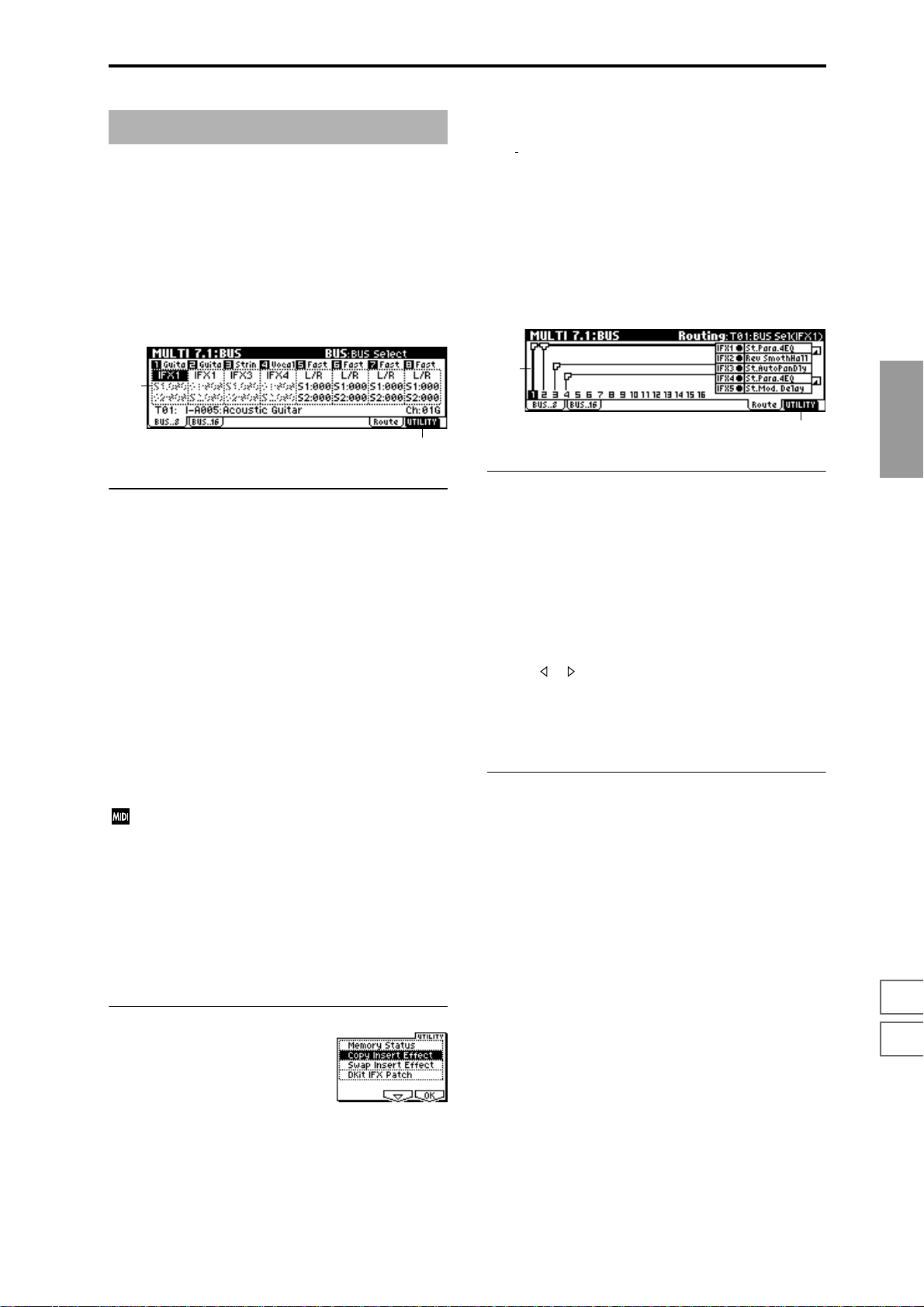
MULTI 7.1: BUS
Specifies the bus to which the program oscillator(s) of each
track 1–8, 9–16 will be sent. You can also set the amount of
signal that will be sent to the master effects.
☞For details on insert effects, refer to “8. Effect Guide”
p.146.
Copy Insert Effect
(☞PROG 7.1–1c)
the MIDI control channel specified in “Control Chan-
Note,
nel” of the 7.2: Insert FX, Setup page will not be copied.
Swap Insert Effect
(☞PROG 7.1–1c)
Note, the MIDI control channel specified in “Control Channel” of the 7.2: Insert FX, Setup page will not be swapped.
7.1–1: BUS..8 (BUS T01–08)
7.1–2: BUS..16 (BUS T09–16)
7.1–1a
7.1–1b
7.1–1(2)a: BUS Select, Send1(MFX1), Send2(MFX2)
BUS Select [DKit, L/R, IFX1...5, 1...4, 1/2, 3/4, Off]
Specifies the output bus for the program oscillators of tracks
1–8 and 9–16.
The state of the settings can be viewed in the Route page.
(
☞COMBI 7.1–1a)
S1 (Send1(MFX1)) [000...127]
S2 (Send2(MFX2)) [000...127]
Here you can adjust the send levels from tracks 1–8, 9–16 to
master effects 1 and 2. This is valid when “BUS Select” is set
either to L/R or Off. If IFX 1, 2, 3, 4, or 5 is selected, the send
level to the master effects 1 and 2 is set by the “S1
(Send1(MFX1))” and “S2 (Send2(MFX2))” parameters
located in the 7.2: Insert FXl, Setup page, after the signal
passes through IFX 1–5.
These settings have no effect if “BUS Select” is set to 1, 2, 3,
4, 1/2 or 3/4.
If “Status” (3.1–1a/2a) is either INT or BTH, CC#93
and #91 can be received to control send 1 and 2 respectively and change their settings. When you switch
multi, tracks whose “Status” is EXT, EX2 or BTH will
transmit these settings via MIDI. This data will be
transmitted on the MIDI channel of each track as set by
“MIDI Channel” (3.1–1a/2a). The actual send level is
determined by multiplying the value of these parameters with the send level settings of the oscillator(s) of
the program used by the track (“S1 (Send1(MFX1))”
and “S2 (Send2(MFX2))” PROG 7.2–1a).
7.1–3: Route (Routing)
7.1–3a
7.1–3b
7.1–3a: Routing Map, BUS Select
This shows the status of the insert effects: the insert effect
routing, the names of the selected effects, the on/off status,
and chaining. The effect type, on/off, and chain settings can
be made in the 7.2: Insert FX, Setup page.
T01...16: BUS Sel
[DKit, L/R, IFX1...5, 1...4,1/2, 3/4, Off]
You can specify the bus to which the program oscillators of
tracks 1–16 will be sent, while viewing a map of the current
settings.
Use the [ ], [ ] keys to select the track, and use the [INC],
[DEC] keys or the [VALUE] dial to set “BUS Select” (7.1–1a/
2a).
These settings can also be made from “BUS Select” (7.1–1/
2).
■ 7.1–3b: UTILITY
☞“Memory Status” (1.1–1c), “Copy Insert Effect,” “Swap
Insert Effect” (7.1–1b/2b), “DKit IFX Patch” (COMBI 7.1–
1b)
MULTI
1.1
2.22.33.13.23.33.44.14.24.34.45.16.17.17.27.3
■ 7.1–1(2)b: UTILITY
☞“Memory Status” (1.1–1c), “DKit IFX Patch” (COMBI 7.1–
1b)
69
Page 77

MULTI 7.2: Insert FX
7.2–1: Setup
Here you can select the type of the insert effects, turn them
on/off, and make chain settings.
7.2–1a
7.2–1c7.2–1b
7.2–1a: Insert FX Setup
IFX1 On/Off — IFX5 On/Off
Insert Effect 1, 5 [000...089: name]
Insert Effect 2, 3, 4 [000...102: name]
Chain [ (Off),
Pan(CC#8) [L000...C064...R127]
BUS Select [L/R, 1, 2, 3, 4, 1/2, 3/4, Off]
S1 (Send1 (MFX1)) [000...127]
S2 (Send2 (MFX2)) [000...127]
These functions are the same as in Program mode. (☞PROG
7.2–1)
However, unlike in Program mode, the “Control Channel”
(7.2–1b) will be the MIDI channel that controls insert effect
dynamic modulation (Dmod) and the “Pan (CC#8),” “Send
1 (MFX1)” and “Send 2 (MFX2)” that follow the insert
effects. The control changes used are the same as in Program
mode.
If “Status” (3.1–1a/2a) is INT or BTH, incoming CC#8,
#93, or #91 will control and change the settings of the
Pan, Send 1, and Send 2 parameters that follow each
insert effect. When you change multis, tracks with a
“Status” of BTH, EXT, or EX2 will transmit and receive
these settings on the MIDI channel specified by “Control Channel” (7.2–1a).
(ON)]
■ 7.2–1c: UTILITY
☞“Memory Status” (1.1–1c), “Copy Insert Effect,” “Swap
Insert Effect” (7.1–1b/2b), “Select by Category” (PROG
7.2–1b)
7.2–2: IFX1
7.2–3: IFX2
7.2–4: IFX3
7.2–5: IFX4
7.2–6: IFX5
Sets the parameters for the effects selected for IFX 1–5 in the
Setup page (
■ 7.2–2(...6)a: UTILITY
☞“Memory Status” (1.1–1c)
☞p.151).
7.2–2a
7.2–7: Route (Routing)
7.2–7a
7.2–7b
7.2–7a: Routing Map
7.2–1b: Control Channel
Control Channel [Ch01...16, All Rt.]
Select the MIDI channel that will control effect dynamic
modulation (Dmod), pan following the insert effect
“Pan (CC#8),” “Send 1 (MFX1),” and “Send 2 (MFX2).”
An asterisk “*” will be displayed at the right of the channel
number Ch01–16 for tracks that are routed to an IFX. If multiple tracks with differing MIDI channel settings are routed,
these channels specify the channel that will be used to control the effect.
All Rt. (All Routed): Control can be performed from any of
the MIDI channels of the tracks that are routed.
If “BUS Select” (7.1–1a/2a) is set to DKit for a track in
which a drum program is selected, the MIDI channel of
that track will be valid if any IFX1–5 is set to All Rt.,
regardless of the drum kit “BUS (BUS Select)” (GLOBAL 5.1–3a) setting or the utility setting “DrumKit IFX
Patch.”
70
This shows the status of the insert effects. This displays the
same contents as the 7.1: BUS, Routing page. (
■ 7.2–7b: UTILITY
☞“Memory Status” (1.1–1c), “Copy Insert Effect,” “Swap
Insert Effect” (7.1–1b/2b), “DKit IFX Patch” (COMBI 7.1–
1b)
☞7.1–3)
Page 78

MULTI 7.3: Master FX
☞For details on the master effects, refer to p.146.
7.3–1: Setup
Here you can select the type of master effects, turn them on/
off, and make chain and master EQ settings.
This is the same as Program mode with the exception of
“MFX1 Control Ch,” “MFX2 Control Ch,” and “MEQ Control Ch.” (
7.3–1a
7.3–1b
7.3–1a: Master FX Setup
☞PROG 7.3: Ed-MasterFX)
7.3–1e7.3–1c7.3–1d
7.3–1d: MEQ Ctrl
MEQ Ctrl (MEQ Control Ch) [Ch01...16, G ch]
Specifies the MIDI channel that will control dynamic
modulation (Dmod) for the master EQ.
G ch: The effect will be controlled on the global MIDI channel “MIDI Channel” (GLOBAL 2.1–1a).
■ 7.3–1e: UTILITY
☞“Memory Status” (1.1–1c), “Select by Category” (PROG
7.3–1d)
Copy Master Effect
(☞PROG 7.3–1d)
Note, the MIDI control channel specified in “Control Channel” of the MFX 1 and 2 pages will not be copied.
MULTI
MFX1 On/Off, MFX2 On/Off [Off, ON]
Master Effect 1, 2 [000...089: name]
Rtn 1, 2 (Return 1, 2) [000...127]
This is the same as in Program mode. Refer to “PROG 7.3–1:
Setup.” However, unlike Program mode, the master effects
will be controlled by the MIDI channel specified by “MFX 1,
2 Control Ch.” The control changes used are the same as in
Program mode.
MFX1, 2 Control Ch [Ch01...16, G ch]
Specifies the MIDI channel that will control dynamic
modulation (Dmod) for the master effects.
G ch: The effect will be controlled on the global MIDI channel “MIDI Channel” (GLOBAL 2.1–1a).
7.3–1b: Master FX Chain
MFX Chain
Direction (Chain Direction)
[MFX1→MFX2, MFX2→MFX1]
Signal (Chain Signal) [LR Mix, L Only, R Only]
Level (Chain Level) [000...127]
This is the same as in Program mode. Refer to “PROG 7.3–1:
Setup.”
Swap Master Effect
(☞PROG 7.3–1d)
Note, the MIDI control channel specified in “Control Channel” of the MFX 1 and 2 pages will not be swapped.
7.3–2: MFX1
7.3–3: MFX2
Here you can set the parameters of the “Master Effect1” and
“Master Effect2” effects that were selected in the Setup page
(
☞p.151).
7.3–2a
■ 7.3–2(3)a: UTILITY
☞“Memory Status” (1.1–1c)
1.1
2.22.33.13.23.33.44.14.24.34.45.16.17.17.27.3
7.3–1c: Master EQ Gain [dB]
Low [–18.0...+18.0]
Mid [–18.0...+18.0]
High [–18.0...+18.0]
This is the same as in Program mode. (☞PROG 7.3–1: Setup)
71
Page 79

7.3–4: Master EQ
The master EQ is a three-band stereo EQ. It is used to perform overall equalizing (tonal adjustment) on the sound
from the L/R bus immediately before it is output to AUDIO
OUTPUT (MAIN OUT) L/MONO and R (
■ 7.3–4a: UTILITY
☞“Memory Status” (1.1–1c)
☞p.203).
7.3–4a
72
Page 80

4. Sampling mode
Sampling mode gives you the capability to record 48 kHz 16
bit samples.
On the TRITON-Rack, “sampling” refers to a process in
which analog audio signals from a mic or audio device connected to the AUDIO INPUT jack are converted into digital
form and recorded into internal memory. The sound that is
converted into digital form can be processed by an insert
effect is being sampled.
The TRITON-Rack comes with 16 Mbytes of sample data
(waveform data). This allows approximately 2 minutes 54
seconds of monaural sampling, or approximately 1 minute
27 seconds of stereo sampling. By installing additional 72
pin SIMM modules, you can expand the memory to a maximum of 96 Mbytes (three 32 Mbyte SIMM modules; the
included 16 Mbyte module must be replaced by a 32 Mbyte
module). In this case, six monaural samples of up to 2 minutes 54 seconds (or stereo samples of up to 1 minute 27 seconds) can be recorded, for a total of 17 minutes 28 seconds of
monaural sampling (or 8 minutes 44 seconds of stereo sampling). (
☞Refer to p.243 for details on installing 72 pin
SIMM modules.)
In Sampling mode, samples that have been sampled or
loaded from storage media can be assigned to an index
(zone) to create a multisample. One multisample can contain
many indexes.
A multisample can easily be converted into a program.(
☞“Conv. To Prog” 1.1–3g). Once the m ultisample is
converted it can be played and programmed like any other
program sound. This program can also be used in Combination or Multi mode.
Samples can also be used as drum samples in a drum kit.
Index001
Top Key
Multisample
Index002
Top Key
Index003
Top Key
Index004
Top Key
When you turn off the power, all multisample and sample data in Sampling mode will be lost. Before you turn
off the power, be sure to save important data to floppy
disk or external SCSI device (
☞BG p.40). If a separately
sold EXB-SCSI option is installed, data can be saved on
an external SCSI device. Immediately after the power is
turned on, memory will contain no multisamples or
samples, so you will first need to load previously-saved
data from a floppy disk or external SCSI device before
you can playback or edit it.
There is no Compare function that allows you to restore
edited data to the state before it was edited. If you wish
to preserve the unedited state of the data, use “Copy
MS” or “Copy SMPL” (1.1–3g) etc. to make a copy of
the multisample or sample before you begin editing.
For some of the utility menu commands in 2.1: Sample
Edit or 3.1: Loop Edit, executing the command without
checking “Overwrite” in the dialog box allows you to
save the unedited sample data while you edit. (
☞2.1–
2e: UTILITY “About Overwrite”)
When executing a sample edit operation or when you
finish recording a stereo sample, you may hear a slight
noise. This does not affect the audio data that has been
edited or sampled.
Cautions regarding sample data
• The sample data memory areas Bank 1–6 each contain
16 MB. Of this 16 MB (8,388,608 samples), sixteen
samples (the first and last eight samples) are used as
internal work area.
• The first and last samples of each sample are used as
internal work area. These two samples are added
automatically when a sample is recorded or when an
.AIFF or .WAVE file is loaded. This means that if you
record a sample of one second, this will result in
48,000 samples of data, but four samples will be added
to this, so that sampling memory will actually contain
48,004 samples of data.
SMPL
1.1
2.13.14.15.15.27.2
Index 001
0000:
Sample A
Multisample
Sample
Index 002
0001:
Sample B
Drum Kit
Index 003
0002:
Sample C
Program OSC (Single/Double)
Program OSC (Drums)
Index 004
0003:
Sample D
Sampling (recording a sample) is performed using the
[F4] (“REC”) and [F5] (“START/STOP”) keys in each
page in the Sampling mode.1.1: Recording of the Sampling mode (For details on sampling procedure, refer to
BG p.68.)
In any page, the selected multisample or sample will
sound when you play the keyboard of a connected
MIDI instrument, letting you hear the results of your
editing in that page.
How the [Audition] key will function in Sampling mode
2.1: Sample Edit, Edit2 page
The sample will be played in one-shot mode in the range
between “S (Edit Range Start)” and “E (Edit Range End)” as
long as you hold down the [AUDITION] key. The sample
will sound at the pitch of the currently selected key (the key
displayed in gray in “Keyboard & Index”: 1.1–1a).
Pages other than the above
The sample of the currently selected “Index” will be played
at the pitch of the currently selected key (the key displayed
in gray in “Keyboard & Index”: 1.1–1a) as long as you hold
down the [AUDITION] key.
Time Slice and Time Stretch dialog boxes
In the Slice Sample dialog box of Utility “Time Slice” (3.1–
2e) and in the Stretch Sample dialog box of Utility “Time
Stretch” (3.1–2e), the sample of the currently selected
“Index” will be played at the original key as long as you
hold down the [AUDITION] key.
73
Page 81

SMPL PAGE MENU
SMPL 1.1: Recording
For details on selecting pages in Sampling mode, refer to
p.1.
Rec 1.1: Recording Record samples. Select the sample or mul-
Smpl 2.1: Sample Edit Perform waveform editing and other editing
Loop 3.1: Loop Edit Set sample playback parameters. Set start,
MS 4.1: Multisample Edit multisamples. Set and edit sample
Mem 5.1: Memory View the remaining memory available for
Ctrl 5.2: Controller Controller settings. (
IFX 7.2: Insert Effect Select the insert effects used for sampling,
tisample to record, and make various
recording settings and AUDIO INPUT set-
☞p.74)
tings. (
on recorded samples or samples that were
loaded into internal memory in Disk mode.
☞p.84)
(
loop start, end address, and turn loop or
reverse playback on/off. (
assign, zone, and original key etc.
☞p.101)
(
multisamples and samples. (
and make settings for them. (
☞p.91)
☞p.103)
☞p.103)
☞p.104)
Here you can set the input level and make other basic settings for sampling (sample recording), and make basic settings for multisamples and samples. Normally you will
record samples in this page.
1.1–1: Sample
Select the multisample and index sample for sampling, and
make basic settings.
1.1–1a
1.1–1b
1.1–1c 1.1–1e
1.1–1a: MS (Multisample Select), Index, Keyboard &
Index
MS (Multisample Select) [000...999]
Selects the multisample.
Each multisample consists of the samples for one or more
indexes (an “index” is a range or zone of keys).
This parameter can also be set from 2.1: Sample Edit–4.1:
Multisample.
Here’s how to create a new multisample.
1 Use numeric keys [0]–[9] to specify the new multisample
number, and press the [ENTER] key to open the “Create
New Multisample” dialog box.
1.1–1d
2 If you wish to create a stereo multisample, check “Ste-
reo.”
3 To create the multisample, press the [F8] (“OK”) key. To
cancel, press the [F7] (“Cancel”) key.
A multisample will be created as follows (example).
Mono 001: NewMS_ _ _ _ _ _001
Stereo 001: NewMS_ _ _ _ _ _001-L,
002: NewMS_ _ _ _ _ _001-R
Index [xxx (001...128)/yyy (001...128)]
Select s the index that you wish to sample, or to which you
wish to assign a sample.
Each zone within a multisample is called an “index.” For
example if a 61-note MIDI keyboard is connected and you
want to divide the multisample into octaves (12 keys), you
would create six zones. Each of these zones is an “index.”
You can assign a sample to each index.
xxx: The selected index. Choose the desired index.
yyy: The total number of indexes in the multisample.
To select an index, hold down the [ENTER] key and
play a note on the keyboard of a connected MIDI instrument. The index that includes the note you played will
be selected. The specified key will be the base key, and
will be displayed in gray in “Keyboard & Index”
(
☞“Keyboard & Index”).
74
Page 82
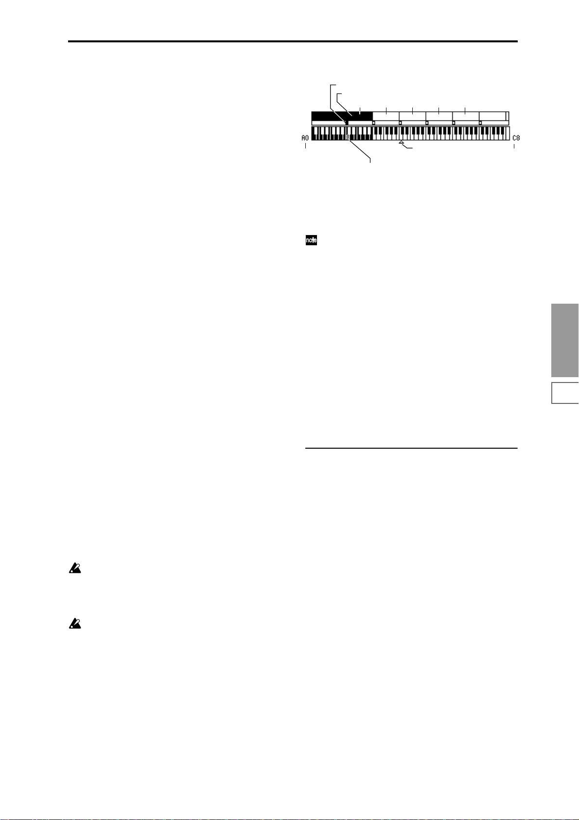
This parameter can also be set in 2.1: Sample Edit–4.1: Multisample. The sampling and editing that you perform in these
pages will apply to the index you select here.
Immediately after the power is turned on, this will be 001/
001. This indicates that only one index exists. T o incr ease the
number of indexes, use “CREATE” in this page. When you
press the [F6] (“CREATE”) key, indexes will automatically
be added from the left-most zone, as 002/002, 003/003, ... The
position, zone width, and original key location of the index
that is created when you press the [F6] (“CREATE”) key can
be set in “Create(Create Zone Preference)” (1.1–3b, 4.1–3a).
You are also free to modify the zone width and original key
location later.
Stereo
A “Stereo” indication will appear at the top right of LCD
display if you have selected a stereo multisample or sample,
or if you recorded a sample with “Mode (Sample Mode)”
(1.1–2a) set to Stereo.
About stereo multisamples and stereo samples
Stereo multisamples: Under the following conditions, two
multisamples will be handled as a stereo multisample.
• If you checked “Stereo” when creating a new
multisample (i.e., selected a new multisample in “MS”
1.1–1a)
• If you executed the Utility “MS To Stereo” (1.1–3g)
• If you sampled with “Mode (Sample Mode)” (1.1–2a) set
to Stereo
In these cases, a stereo multisample that meets the following
conditions will be created automatically.
1. The last two characters of the two multisample names
will be -L and -R respectively, and the earlier portion of
the names are identical.
2. The two multisamples will have the same number of
indexes, and their zone settings are identical.
Stereo samples: Under the following condition, two samples will be handled as a stereo sample.
• When the samples were recorded with a “Mode
(Sample Mode)” (1.1–2a) setting of Stereo.
• If you executed the Utility “SMPL To Stereo” (1.1–3g)
In this case, a stereo sample that meets the following conditions will be created automatically.
1. The last two characters of the sample name will be -L and
-R respectively, and the earlier portion of the names are
identical.
2. Two samples that satisfy condition 1. for stereo multi-
samples are selected.
Stereo multisamples and samples are distinguished
internally by their multisample name or sample name.
If you use Utility “Rename MS” or “Rename SMPL”
(1.1–3g) etc. to modify the multisample name or sample
name, please pay attention to the above conditions.
As a condition of a stereo sample, the sampling rates
must be identical. You can verify the sampling rate of a
sample by using the Utility “Rate Convert” (2.1–2e). Be
aware that if you use Utility “Rate Convert” to convert
the -L and -R samples to differing sampling rates, they
will not be handled as a stereo sample.
Keyboard & Index
Original Key (currently selected Original Key is reversed)
Index zone (currently selected Index is reversed)
Index02 Index03 Index04 Index05
Index01
Lowest note of the
displayed keyboard
By holding down the [ENTER] key and play a note on the keyboard of a
connected MIDI instrument, you can select the corresponding
index, and the specified key will be the base key and will be shown in gray.
C4 key
Highest note of the
displayed keyboard
This shows the zones and original key locations of the currently selected multisample. The white triangle indicates the
C4 key. The note numbers at left and right are the range of
notes displayed.
The key displayed in gray is called the base key, and
functions as follows.
• In the 2.1: Sample Edit, Edit2 page, pressing the
[AUDITION] key will play the sample of the selected
“Index” from “S (Edit Range Start)” to “E (Edit Range
End)” in one-shot mode. At this time, the sample will
sound at the pitch of the base key. In pages other than
the 2.1: Sample Edit, Edit 2 page, the sample of the
currently selected “Index” will continue playing at the
pitch of the base key as long as you hold down the
[AUDITION] key.
• The grid display in 2.1: Sample Edit and the 3.1: Loop
Edit Edit2 page is displayed relative to the playback
pitch at the base key and the specified tempo BPM/
resolution (set in the “Grid” utility).
• The Utility “Pitch BPM Adj.” (4.1–3b) function is
relative to the playback pitch of the base key.
You can use Utility “Keyboard Disp.” (1.1–3g) to change the
displayed range of the keyboard.
1.1–1b: SMPL, Orig.K, TopK
Here you can set the sample, original key, and range of the
selected index.
SMPL (Sample Select)
[----: ---No Assign----, 0000...3999]
Selects a sample that you recorded or that you loaded in
Disk mode. That sample will sound when you play a note
within the index range on a connected MIDI instrument.
This parameter can also be set in 2.1: Sample Edit–4.1: Multisample. The sampling and editing operations that you perform in these pages will affect the sample you select here.
---: ---No Assign----: A sample has not been assigned to the
index. Playing a note on a connected MIDI instrument will
not produce sound.
To record a sample, select a vacant sample such as 0000:.
When you record a sample, data will be loaded into the
selected sample.
The sample name (such as NewSample_0000) will be shown
beside the number. This sample name can be modified using
the Utility “Rename SMPL” (1.1–3g).
You can also record a sample even when ----:---No Assign---is displayed. In this case, a sample number will be selected
automatically.
Even if you record to a sample that already contains data,
the selected sample will not be overwritten –the data will
automatically be sampled to a vacant sample number, and
the newly recorded sample will replace the previous sample
in the index. If you wish to delete a sample, execute the Utility “Delete SMPL” (1.1–3g).
SMPL
1.1
2.13.14.15.15.27.2
75
Page 83
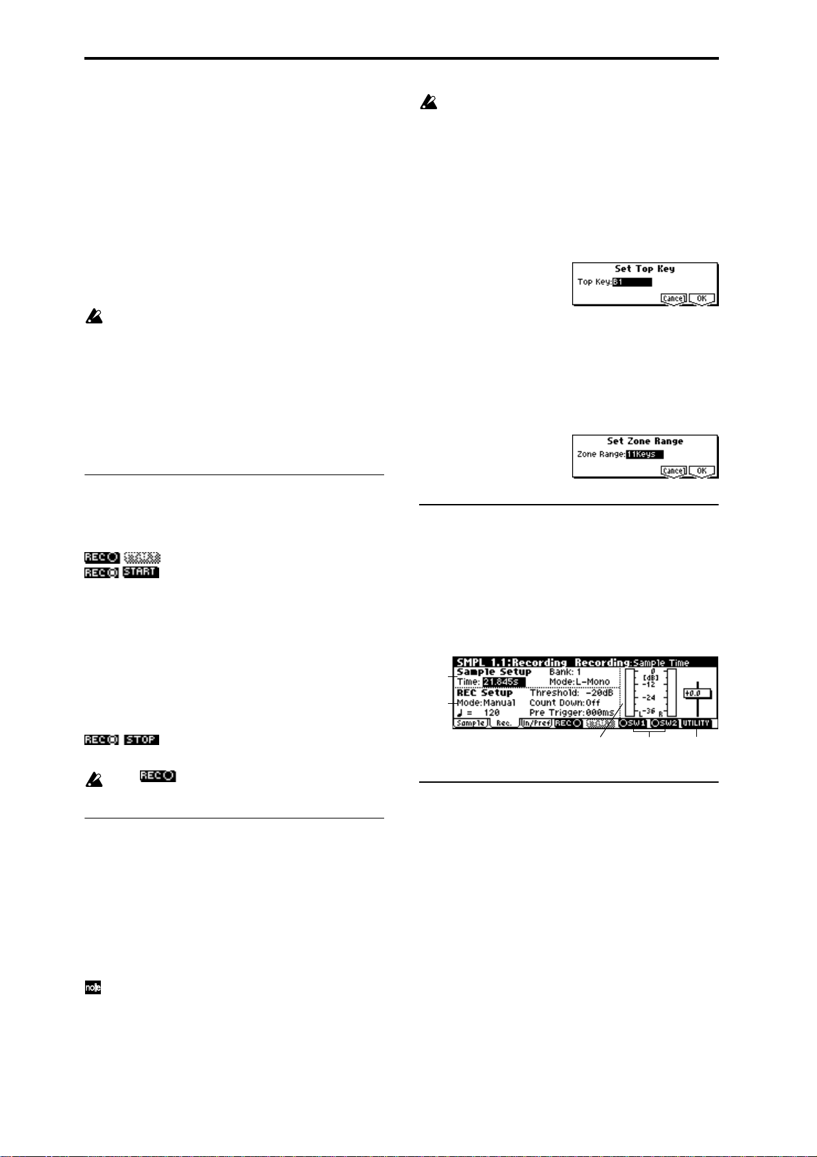
Orig.K (Original Key) [C–1...G9]
Specifies the key that will play the sample at its original
pitch (i.e., the pitch at which it was recorded). The pitch will
change in semitone steps relative to the original key.
For example, suppose that you set “Orig.K” to F2, and
recorded a sample. If the index zone is C2–B2, playing the F2
key on a connected MIDI instrument will sound the sample
at its actual pitch. Playing the F#2 key will sound the sample
a semitone higher. Playing the E2 key will sound the sample
a semitone lower. This sampled sound will change pitch in
semitone steps in the range from B2 down to C2, centered at
F2.
The location of the original key can also be viewed in “Keyboard & Index.”
If “Constant Pitch” (4.1–2a) is checked, the sample will
be sounded at its original pitch by all notes in the zone.
TopK (Top Key) [C–1...G9]
Specifies the highest key in the zone of the index. The zone
is defined by this “TopK.”
For example, suppose that you set a “TopK” of B2 for index
001/002, and a “TopK” of B3 for index 002/002. This means
that the zone of index 001 will be B2 and lower, and the zone
of index 002 will be C3–B3.
■ 1.1–1c: REC, START/STOP
If when you execute “CREATE” (1.1–1d, 4.1–1c) or
“INSERT” (4.1–1c) it is not possible to create a new
index according to your Create (Create Zone Preference) settings, one of the following dialog boxes will
appear. If you wish to create a new index, perform the
following procedure.
• Set Top Key: Select “Index” 001, set “Pstn (Position)”
(1.1–3b, 4.1–3a) to L (Left), and execute “CREATE” or
“INSERT” to open the dialog box. So that a new index
can be created at the left of index 001, reset the “Top
Key” setting, and press the [F8] (“OK”) key.
• Set Zone Range: If you execute “CREATE” when it is
not possible to create a new index according to the
Create (Create Zone Preference) settings, the following
dialog box will appear. This dialog box will also
appear if you execute “INSERT” when it is not
possible to create a new index with the contents of the
“CUT” or “COPY” (4.1–1c). Reset the “Range (Zone
Range)” (1.1–3b, 4.1–3a), and press the [F8] (“OK”) key.
This is where you sample (i.e., record a sample).
Use the [F4] (“REC”) key and [F5] (“START/STOP”) keys to
sample.
: This is the normal state.
: Press the [F4] (“REC”) key to enter sam-
pling standby mode. To cancel recording, press the [F4]
(“REC”) key once again.
When “Mode (REC Mode)” is Manual, pressing the [F4]
(“REC”) key will enter sampling standby mode. Then when
you press the [F5] (“START”) key, recording will begin.
(
☞”Mode (REC Mode),” “Count Down”)
When “Mode (REC Mode)” is Auto, pressing the [F4]
(“REC”) key and then the [F5] (“START”) key will enter
sampling standby mode. Recording will begin when the
input level exceeds the “Threshold” value. (
Mode),” “Threshold”)
: Press the [F5] (“STOP”) key to stop record-
ing.
In the state, it is not possible to edit using the
Utility commands.
■ 1.1–1d: CREATE
Here you can create an index. Use this when you wish to
add a sample to a multisample.
When you press the [F6] (“CREATE”) key, a new index will
be created according to the settings of the Create (Create
Zone Preference) (1.1–3b, 4.1–3a) parameters “Pstn (Position),” “Range (Zone Range),” and “Orig.K (Orig.K Position).”
If you wish to delete an existing index or to exchange indices, use 4.1: Multisample.
“CREATE” will be displayed if the 1.1: Recording, Sample page or the 4.1: Multisample, Edit 1, Edit 2 pages are
selected.
☞”Mode (REC
■ 1.1–1e: UTILITY
☞“Delete SMPL,” “Copy SMPL,” “Move SMPL,” “Rename
SMPL,” “SMPL To Stereo,” “Delete MS,” “Copy MS,”
“Move MS,” “Rename MS,” “MS To Stereo/MS To
Mono,” “Conv. To Prog,” “Keyboard Disp.” (1.1–3g)
1.1–2: Rec. (Recording)
1.1–2a
1.1–2b
1.1–2c
1.1–2a: Sample Setup
Here you can select the memory bank into which you will
sample, specify the sampling time, and select either mono or
stereo sampling.
Time (Sample Time)
Specifies the time that you wish to sample. This can be set in
0.001 second increments. Immediately after the power is
turned on, this will show the remaining memory (available
sampling time) of the selected memory bank. If you record a
sample in this condition (“REC”→“START”→“STOP”), the
change in time will be displayed automatically.
If you have sufficient memory, it is a good idea to set an
ample “Time (Sample Time),” and to use the Utility “Truncate” (2.1–2e, 3.1–2e) after you sample to delete unwanted
portions of the sample and reduce it to the minimum size
necessary. You can also press the [F5] (“START/STOP”) key
to stop recording after you have recorded the desired material (
☞ For details on the sampling procedure, refer to BG
p.67).
1.1–2d 1.1–2e
76
Page 84
The remaining amount of memory will depend on the following conditions.
1. The amount of memory that is installed.
2. Whether the sample is stereo or mono. When the “Mode
(Sample Mode)” (1.1–2a) is set to Stereo, the memory
capacity will be halved.
3. The time specified for “Pre Trigger” (1.1–2b: a function
that automatically samples the sound even before you
begin sampling) will be subtracted from the amount of
memory that actually remains.
Bank (RAM Bank) [1...6]
Selects the memory bank into which you will sample. The
sample data memory is organized into six banks, each with
16 Mbytes. The TRITON-Rack comes with 16 Mbytes of
memory (SIMM) installed as standard. In this case, (RAM)1
will always be selected as the memory bank, and it will not
be possible to select (RAM)2, 3, 4, 5 or 6.
By installing separately sold 72-pin SIMM boards you can
expand the memory to a maximum of 96 Mbytes (three 32
Mbyte SIMM boards) (
Installed SIMM boards and available banks
SIMM Slot No. SIMM Bank (RAM Bank)
Slot1 16 Mbyte (factory-installed) 1
Slot2 16Mbyte 3
Slot3 16Mbyte 5
On the TRITON-Rack, a 16 Mbyte SIMM is factoryinstalled in slot 1. For “Bank (RAM Bank)” you can
select 1. For example if slot 1 contains the factoryinstalled 16 Mbyte SIMM and you have installed a 32
Mbyte SIMM in slot 2 and a 16 Mbyte SIMM in slot 3,
“Bank (RAM Bank)” can be set to 1 (16 Mbyte), 3 (16
Mbyte), 4 (16 Mbyte), or 5 (16 Mbyte). Banks are in 16
Mbyte units.
(If 32 Mbyte SIMMs are installed in slot 1, slot 2, and
slot 3, you will be able to select all banks, and the total
capacity will be 96 Mbytes.)
☞p.243).
32Mbyte 1, 2
32Mbyte 3, 4
32Mbyte 5, 6
Mode (Sample Mode) [L-Mono, R-Mono, Stereo]
Select s the channel(s) to be sampled, to specify whether a
mono or a stereo sample will be recorded.
Depending on the “Input1, Input2” (1.1–3a) settings, the
external source from the AUDIO INPUT 1 and 2 jacks will be
sent, either as direct sound without being routed through an
effect, or as effect-processed sound routed through an insertion effect, to the L/R bus and sampled from the internal L
and R channels.
L-Mono: The sound of the internal L channel will be sampled in mono.
R-Mono: The sound of the internal R channel will be sampled in mono.
Stereo: The sound of the internal L and R channels will be
sampled in stereo. When you sample in stereo, a stereo multisample or sample will be created.
Example 1:
Sampling a monaural source connected to AUDIO INPUT 1
without applying internal effects
Input1 “Lvl (Level)” (1.1–3a) 127
Input1 “Pan” (1.1–3a) L000
Input1 “BUS (BUS(IFX)Select)”(1.1–3a) L/R
“Recording Level” (1.1–2c, 1.1–3e)as appropriate
“Mode (Sample Mode)” (1.1–2a) L-Mono
Example 2:
A monaural source connected to AUDIO INPUT 1 routed
through the internal insertion effect IFX 052: Rev Hall, and
sampled in stereo
Input1 “Lvl (Level)” (1.1–3a) 127
Input1 “Pan” (1.1–3a) C064
Input1 “BUS (BUS(IFX)Select)”(1.1–3a) IFX1
IFX select (7.2) 052: Reverb Hall
and make settings
“Recording Level” (1.1–2c, 1.1–3e)as appropriate
“Mode (Sample Mode)” (1.1–2a) Stereo
Example 3:
A stereo source connected to AUDIO INPUT 1 and 2, and
sampling without applying internal effects
Input1 “Lvl (Level)” (1.1–3a) 127
Input1 “Pan” (1.1–3a) L000
Input1 “BUS (BUS(IFX)Select)”(1.1–3a) L/R
Input2 “Lvl (Level)” (1.1–3a) 127
Input2 “Pan” (1.1–3a) R127
Input2 “BUS (BUS(IFX)Select)”(1.1–3a) L/R
“Recording Level” (1.1–2c, 1.1–3e)as appropriate
“Mode (Sample Mode)” (1.1–2a) Stereo
Example 4:
A stereo source connected to AUDIO INPUT 1 and 2, routed
through internal insertion effect IFX1 008: St.Graphic 7EQ,
and sampled in stereo
Input1 “Lvl (Level)” (1.1–3a) 127
Input1 “Pan” (1.1–3a) L000
Input1 “BUS (BUS(IFX)Select)”(1.1–3a) IFX1
Input2 “Lvl (Level)” (1.1–3a) 127
Input2 “Pan” (1.1–3a) R127
Input2 “BUS (BUS(IFX)Select)”(1.1–3a) IFX1
IFX1 select
“Recording Level” (1.1–2c, 1.1–3e)as appropriate
“Mode (Sample Mode)” (1.1–2a) Stereo
When you finish recording a stereo sample, you may
hear a slight noise. This does not affect the audio data
that has been sampled.
(7.2) 008: St.Graphic
7EQ and make settings
1.1–2b: REC Setup
Mode (REC Mode) [Manual, Auto]
Select s the method by which sampling will be started.
Manual: Sampling will start when you press the [F5]
(“START”) key from the sampling standby condition.
1 Press the [F4] (“REC”) key to enter sampling standby
mode.
2 Use the “Recording Level” (1.1–2c, 1.1–3e) slider to
adjust the sampling level.
Be careful of changes in the monitoring volume level
(
☞“Recording Level”).
SMPL
1.1
2.13.14.15.15.27.2
77
Page 85
3 Sampling will begin when you press the [F5] (“START”)
key. If you use the “Count Down” function, pressing the
[F5] (“START”) key will cause sampling to begin after the
metronome sounds a count-down.
4 To stop sampling, press the [F5] (“STOP”) key once
again. Sampling will end automatically if you continue
sampling to the end of the “Time (Sample Time)” (1.1–
2a).
Auto: Sampling will begin automatically when the input
level exceeds the “Threshold” setting.
1 Perform steps 1 and 2 described above.
2 Adjust the “Threshold” setting. The black triangles at
both sides of the “Recording Level” level bar display will
indicate the “Threshold” level. Normally, this should be
set as low as possible without allowing noise to trigger
sampling.
3 Press the [F5] (“START”) key.
Sampling will automatically begin when the input level
exceeds the “Threshold” setting.
4 To stop sampling, perform step 5 described above.
Threshold [–63dB...0dB]
When performing auto sampling (“Mode (REC Mode)”
Auto), this sets the level at which sampling will begin
(
☞“Mode (REC Mode)” Auto, step 3).
This will not be displayed if “Mode (REC Mode)” is set
to Manual.
Count Down (Count Down REC) [Off, 4, 8, 3, 6]
When you begin sampling with “Mode (REC Mode)” set to
Manual, this parameter specifies whether there will be a
count-down before sampling begins.
Off: When you press the [F5] (“START/STOP”) key from
sampling standby mode, sampling will begin immediately.
4, 8, 3, 6: When you press the [F5] (“START/STOP”) key
from sampling standby mode, sampling will begin after a
count-down of the specified length, based on the tempo of “
(Tempo).” If you specify 4, the count will be 4-3-2-1-0, and
sampling will begin on the count of 0.
This will not be displayed if “Mode” is set to Auto.
(Tempo) [040...240]
This sets the tempo of the count-down when “Count Down”
is used.
The tempo specified here will also be used when the LFO or
delay time of the insert effect is controlled by the BPM/
MIDI SYNC function during sampling (
☞p.212). This can
also be set by the REALTIME CONTROLS C-mode
[TEMPO] knob.
Pre Trigger (Pre Trigger REC) [000...500ms]
When sampling the sound that occurs before sampling is
actually triggered, this setting specifies the time length that
will be “pre-sampled.”
When sampling in auto mode (“Mode (REC Mode)” Auto),
sampling will begin when the input signal exceeds the specified threshold level “Threshold” (1.1–2b). However
depending on the “Threshold” settings, the early portion of
the attack sound may be lost, and in such cases you can use
“Pre Trigger.”
Also, when sampling manually (“Mode (REC Mode)” Man-
ual) and using “Count Down,” you may intend to play your
instrument etc. at precisely the downbeat but actually be
slightly ahead of the beat. In such cases, you can use Pre
Trigger REC to sample without loosing the beginning of the
note.
If you increase this value, you will always be sampling
more than you need. Normally you should leave this
set at 000ms, and set it to a minimal value only when
necessary.
1.1–2c: Recording Level
Recording Level [–inf, –72.0... 0.0...+18.0dB]
Adjust the final level of the signal that will be sampled.
This can also be set in the Input/Pref page.
When you press the [F4] (“REC”) key you will enter sampling standby mode, and you will be able to adjust the signal level.
Initially you should set this to 0.0, and make adjustments so
that the level of the bar is as high as possible without
exceeding 0 dB. If 0 dB is exceeded, “CLIP!” will be displayed. This indicates that the sampling signal level is excessive. Adjust the level so that “CLIP!” does not appear.
In order to sample with the maximum dynamic range,
use the [INPUT] knob to adjust the level as high as possible without making “ADC OVER!” appear. Then set
“Lvl” (Input/Pref page) to 127, and adjust “Recording
Level” (Recording page, Input/Pref page) as high as
possible without making the “CLIP!” indication appear.
In the sampling standby condition after you press the
[F4] (“REC”) key, the sound that is output from the
AUDIO OUTPUT L/MONO, R and from the headphones will be adjusted by the “Recording Level,” but
when you cancel sampling standby condition or cancel
sampling, the sound will be output at the 0 dB level. If
you have lowered the “Recording Level” below 0 dB,
please be careful of sudden changes in volume.
If the sound is still distorted even if you lower the
“Recording Level,” it is possible that distortion is
occurring in the input stage of the AUDIO INPUT, or
that distortion is being caused by the settings of the
internal effect.
Excessive signal levels in the input stage of the AUDIO
INPUT can be verified in the Recording page, Input/
Pref page. If an indication of “ADC OVER!” appears
above the “Recording Level” bar display, the distortion
is due to excessive levels in the input stage of the
AUDIO INPUT. Adjust the [INPUT] knob until the
"ADC OVER!" display no longer appears.
If there is still distortion even after [INPUT] has been
lowered, it is possible that the distortion is being caused
by the settings of the internal effect. Lower the Input 1,
2 “Lvl” (Input/Pref page), or adjust the effect settings.
CLIP!
“Mode” (1.1–2a)
L-Mono
R-Mono
Stereo
AUDIO INPUT
ADC OVER!
INPUT
(MIN...MAX)
Analog to Digital
Converter
ADC
“Lvl” (1.1–3a)
[127=0dB]
“Pan” (1.1–3a)
Insert
Effects
“Recording Level” (1.1–2c)
[–inf ... 0.0dB ... +18.0dB]
If you have sampled at a low input level, you can execute Normalize in Utility “Norm./Level Adj.” (2.1–2e)
to amplify the level to the maximum possible without
clipping.
78
Page 86

■ 1.1–2d: SW1, SW2
1.1–3b: Create (Create Zone Preference)
Effect dynamic modulation for the functions assigned to
“SW1” and “SW2” can be controlled in realtime while you
sample. This setting is made in 5.2: Ctrl Setup.
: On, : Off
■ 1.1–2e: UTILITY
☞“Delete SMPL,” “Copy SMPL,” “Move SMPL,” “Rename
SMPL,” “SMPL To Stereo,” “Delete MS,” “Copy MS,”
“Move MS,” “Rename MS,” “MS To Stereo/MS To
Mono,” “Conv. To Prog,” “Keyboard Disp.” (1.1–3g)
1.1–3: In/Pref (Input/Preference)
Specify the input level from the rear panel AUDIO INPUT 1,
2, and set pan and balance. You can also set other setup
parameters.
1.1–3a
1.1–3b
1.1–3c
1.1–3d 1.1–3e
1.1–3a: Input1, Input2
Here you can make adjustments for the input stage of the
audio signal received at AUDIO INPUT 1 and 2.
These settings are valid only in Sampling mode. These
settings will also be valid when you move from Sampling mode to Global mode.
In modes other than Sampling mode, settings for Audio
Input 1 and 2 are made in “Audio In (Setup for COMBI,
PROG, MULTI)” (GLOBAL 1.1: System, Audio In).
Lvl (Level) [000...127]
Specifies the level of the signal immediately after the analog
audio signal from AUDIO INPUT 1 and 2 is converted into a
digital signal. Normally you will set this to 127.
If you hear distortion even after lowering this level, it is possible that the distortion is occurring before the A/D converter. Adjust the [INPUT] knob or the output level of your
external sound source so that the “ADC OVER!” indication
above the “Recording Level” display does not appear.
Pan [L000...C064...R127]
Sets the panning of the analog audio signal from AUDIO
INPUT 1 and 2. Normally you will set Input 1 to L000 and
Input 2 to R127. This allows you to sample a stereo audio
source in stereo (
☞For example settings, p.77, BG p.68).
BUS (BUS(IFX) Select) [L/R, IFX1...5, Off]
Select s the bus.
L/R: Select this when you wish to sample the incoming analog audio signal without applying an insert effect. Normally
you will select L/R.
IFX1...5: Select one of these when you wish to apply an
insert effect to the incoming audio sample as you sample it
(
☞p.144).
Off: The analog audio signal will not be input.
1.1–3f 1.1–3g
These settings determine the initial state of the indexes that
are created when you press the [F6] (“CREATE”) key (1.1–
1d, 4.1–1c). Each new index will be created according to the
settings you make here, but you are free to modify the settings later.
Pstn (Position) [R, L]
Specifies whether the new index will be created at the right
or left of the selected index.
R (Right): The new index will be created at the right of the
currently selected index.
L (Left): The new index will be created at the left of the currently selected index.
Range (Zone Range) [001...127]
Specifies the key range of the zone of the newly created
index.
001: A single note of the keyboard will be the index. The
sample of the index will sound at its original key when you
play that note. This setting can be used similarly to pad
(keyboard) type samplers.
002...127: The sample will change pitch in semitone steps
across the specified number of keys, centered on the original
key “Orig.K” (1.1–1b, 4.1–1b). If “Constant Pitch” (4.1–2a) is
checked, the pitch will not change.
Orig.K (Original Key Position) [Btm, Cntr, Top]
Specifies where the original key will be located in the zone
(specified by “Zone Range”) for a newly created index.
Btm (Bottom): The lowest key in the zone will be the original key.
Cntr (Center): The middle key in the zone will be the original key.
Top: The top key in the zone will be the original key.
1.1–3c: Auto Loop
Auto Loop (Auto Loop On) [Off, On]
On (Checked): The recorded sample will automatically be
played with looping turned on (
☞“3.1: Loop Edit”).
1.1–3d: Metro (Count Down REC Metronome)
BUS (Metronome BUS) [L/R, 1, 2, 3, 4]
Specifies the output destination of the metronome sound
played by “Count Down” (1.1–2b).
L/R: The metronome will be output from OUTPUT (MAIN)
L/Mono, R, and the headphones.
1, 2, 3, 4: The metronome will be output from OUTPUT
(INDIVIDUAL) 1, 2, 3, or 4 respectively.
Lvl (Metronome Level) [000...127]
Specifies the level of the metronome sound played by
“Count Down.”
1.1–3e: Recording Level
[–inf, –72.0... 0.0...+18.0]
Adjusts the signal level at the final stage of sampling (☞1.1–
2c).
SMPL
1.1
2.13.14.15.15.27.2
79
Page 87

■ 1.1–3f: SW1, SW2
Effect dynamic modulation for the functions assigned to
“SW1” and “SW2” can be controlled in realtime while you
sample. (
☞1.1–2d)
■ 1.1–3g: UTILITY
For details on how to select the desired utility function, refer
to “PROG 1.1–1d: UTILITY.”
Delete SMPL (Delete Sample)
This command deletes the currently selected sample, or
samples that are not mapped to (i.e., used by) any multisample or drum kit, or all samples.
1 Select “Delete SMPL” to open the following dialog box.
2 Use the [INC], [DEC] keys or the [VALUE] dial to select
the sample(s) that you wish to delete.
Selected: The currently selected sample will be deleted.
The sample assignment for “Index” (1.1–1a) will change
to ---No Assign---.
Unmapped Samples: Delete all samples that are not
mapped to (used by) any multisample or drum kit.
All Samples: All samples in memory will be deleted.
The sample assignments of all multisamples will change
to ---No Assign---.
3 To execute the Delete Sample command, press the [F8]
(“OK”) key. To cancel, press the [F7] (“Cancel”) key.
If the sample data (waveform data) of the sample you
delete is being used by another sample, the sample data
itself will not be deleted. Only the sample will be deleted.
Copy SMPL (Copy Sample)
This command copies the currently selected sample to
another sample.
The sample number of the copy destination will automatically be added to the sample name. If necessary,
use “Rename SMPL” (1.1–3g) to rename it. At this time,
be careful that the name is not identical to any other
sample. (The sample name is used to distinguish stereo
samples.
1 Use “SMPL” (1.1–1b) to select the copy source sample.
2 Select “Copy SMPL” to open the following dialog box.
☞p.75)
4 If you check “with Sample Data”: Executing the copy
will simultaneously copy the sample data (waveform
data) as well. The copy source and copy destination samples will exist as completely independent samples. For
example, you would use this when you wish to start with
the same sample data, and edit it separately in 2.1: Sample Edit to create two or more different types of sample.
If you do not check “with Sample Data”: Executing the
copy will not copy the sample data (waveform data). The
newly created sample will share the sample data of the
copy source sample. For example, you would use this
when you wish to use 3.1: Loop Edit to create two or
more versions of the same sample data with different
loop addresses. Sample memory area will not be consumed by this type of copy. If you use 2.1: Sample Edit to
edit the sample data, the results will affect all samples
that share this sample data.
Sample Memory
"Copy SMPL"
with Sample Data
"Copy SMPL"
0000: NewSample_0000
0001: NewSample_0001
0000: NewSample_0000
0001: NewSample_0001
Sample Data
Sample Data
Sample Memory
Sample Data
5 To execute the Copy Sample command, press the [F8]
(“OK”) key. To cancel, press the [F7] (“Cancel”) key.
Move SMPL (Move Sample)
This command lets you move the currently selected sample
to the specified number (i.e., to change the sample number),
or to rearrange the sample numbers so that they start from
0000 after samples have become discontinuous as a result of
creating or editing. (
When you reassign the sample numbers, the sample numbers within the multisamples and drum kits that use these
sample will also be automatically reassigned. (This means
that the samples of the multisamples and drum kits need not
be reassigned following this operation.)
☞Following illustration)
3 Use “To: Sample No.” to specify the copy destination
sample number.
When copying a stereo sample, specify both the L
and R channels for the copy destination sample number.
80
1 Use “SMPL” (1.1–1b) to select the copy source sample.
2 Select “Move SMPL” to open the following dialog box.
3 Use “To” to specify the move destination sample number.
When moving a stereo sample, you must move
the samples individually.
If you wish to reassign (pack) all sample numbers starting at 0000, check “Optimize Empty Sample No.”
Page 88

4 If “Adjust Sample Assign in Drum Kit” is checked, and
if the samples being moved are mapped to (used by) a
drum kit, those sample numbers will also be automatically modified. Normally you will leave this checked.
Samples mapped to (used by) multisamples will be automatically changed to the new sample numbers regardless
of this setting.
5 To execute the Move Sample operation, press the [F8]
(“OK”) key. To cancel without executing, press the [F7]
(“Cancel”) key.
Example)
If data already exists at the move destination sample
number, the sample will not be overwritten; instead, all
subsequent samples will be renumbered upward.
Move 0003 to 0001
Example)
If there is no empty sample number and forward movement is not possible, samples will be renumbered downward.
Move 3996 to 3999
Rename SMPL (Rename Sample)
This command renames the currently selected sample.
1 Use “SMPL” (1.1–1b) to select the sample whose name
you wish to change.
2 Select “Rename SMPL” to open the following dialog box.
3 Press the [F5] (“Name”) key to move to the text dialog
box, and input the sample name (maximum of sixteen
characters).
If the multisample is stereo and a stereo sample is
selected, you can input up to fourteen characters for the
sample name. This is because the last two characters are
reserved for -L and -R. If you rename up to fourteen char acters of the sample of either the L or the R channel, the
other sample will automatically be renamed.
4 To execute the Rename Sample command, press the [F8]
(“OK”) key. To cancel, press the [F7] (“Cancel”) key.
SMPL To Stereo (Change Sample Type)
This command changes a mono sample into a stereo sample.
This can be executed only if the selected sample is mono.
1 Use “SMPL” (1.1–1b) to select the sample that you wish
to convert to stereo.
2 Select “SMPL To Stereo” to open the following dialog
box.
3 To execute the Change Sample Type command, press the
[F8] (“OK”) key. To cancel, press the [F7] (“Cancel”) key.
When you execute this command, the sample type will
change as follows.
• The selected sample will become a stereo sample. “–L”
will be overwritten into the last two characters of the
sample name.
• An identically named sample will be created with “–R”
as the last two characters of the sample name.
Also, if the selected multisample is mono, it will change
to stereo.
• The last two characters of the multisample name will be
overwritten as “–L”.
• A new multisample will be created with the same name,
but whose last two characters are “–R”.
• The stereo sample that was created will be assigned
automatically.
Delete MS (Delete Multisample)
This command deletes the currently selected multisample or
all multisamples.
1 Use “MS” (1.1–1a) to select the multisample that you
wish to delete.
2 Select “Delete MS” to open the following dialog box.
3 All Multisamples: Check this if you wish to delete all
multisamples.
4 Delete Samples too?: Check this if you wish to simulta-
neously delete the samples that are included in the multisample being deleted. However, samples that are
mapped to (used by) other multisamples or drum kits
will not be deleted.
5 To execute the Delete Multisample command, press the
[F8] (“OK”) key. To cancel, press the [F7] (“Cancel”) key.
Even if you also choose to delete the samples that are
included in the deleted multisample(s), any sample
data (waveform data) used by these samples that is
shared with other samples will not be deleted. Only the
sample itself will be deleted.
Copy MS (Copy Multisample)
This command copies the selected multisample to another
multisample.
The copy destination multisample number will automatically be included in the multisample name of the
copy destination. If necessary, use “Rename MS” (1.1–
3g) to rename it. When doing so, make sure that the
name is not identical to any other multisample name.
(The multisample name is used to distinguish stereo
multisamples.
1 Use “MS” (1.1–1a) to select the copy source multisample.
2 Select “Copy MS” to open the following dialog box.
3 Use “To: Multisample No.” to specify the copy destina-
tion multisample number.
When copying a stereo multisample, copy both
the L and R channels of the copy destination multisample
number.
☞p.75)
SMPL
1.1
2.13.14.15.15.27.2
81
Page 89
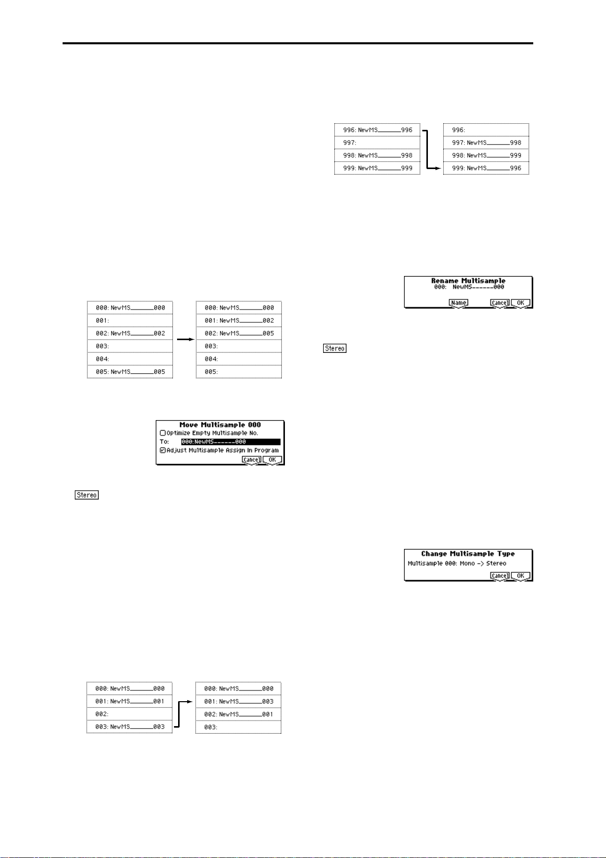
4 To execute the Copy Multisample command, press the
[F8] (“OK”) key. To cancel, press the [F7] (“Cancel”) key.
When a multisample is copied, the samples assigned to
the multisample will also be copied at the same time. At
this time, they will be automatically copied to vacant
sample numbers. The sample data (waveform data) will
be shared between the copy source and copy destination.
(Additional sample memory area will not be consumed.)
Move MS
This command lets you move the currently selected multisample to the specified number (i.e., to change the multisample number), or to rearrange the multisample numbers
so that they start from 000 after multisamples have become
discontinuous as a result of creating or editing. (
illustration)
When you reassign the multisample numbers, the multisample numbers within the programs that use these multisamples will also be automatically reassigned. (This means that
you do not need to reselect the multisamples in Program
mode following this operation.)
1 Use “MS” (1.1–1a) to select the multisample that you
wish to move.
2 Select “Move MS” to open the following dialog box.
☞Following
Example)
If there is no empty multisample number and forward
movement is not possible, multisamples will be renumbered downward.
Move 996 to 999
Rename MS (Rename Multisample)
This command modifies the name of the currently selected
multisample.
1 Use “MS” (1.1–1a) to select the multisample that you
wish to rename.
2 Select “Rename MS” to open the following dialog box.
3 Press the [F5] (“Name”) key to move to the text dialog
box, and input the multisample name (up to sixteen characters).
If the selected multisample is stereo, up to four-
teen characters can be input as the multisample name.
This is because the last two characters are reserved for -L
and -R. If you rename up to fourteen characters of the
multisample of either the L or the R channel, the other
multisample name will automatically be renamed.
4 To execute the Rename Multisample command, press the
[F8] (“OK”) key. To cancel, press the [F7] (“Cancel”) key.
3 In “To,” specify the move destination multisample num-
ber.
When moving a stereo multisample, you will
need to move each part separately.
If you wish to rearrange all multisamples consecutively,
check “Optimize Empty Multisample No.”
4 If “Adjust Multisample Assign in Program” is checked
and if the multisamples being moved are used in programs, the multisample numbers of the programs will
also be reassigned automatically. Normally you will
leave this checked.
5 To execute the Move Multisample command, click the
[F8] (“OK”) key. If you decide not to execute, click the
[F7] (“Cancel”) key.
Example)
If data already exists at the move destination multisample number, the multisample will not be overwritten;
instead, all subsequent multisamples will be renumbered
upward.
Move 003 to 001
MS To Stereo/MS To Mono (Change Multisample Type)
This command converts a mono multisample to stereo, or a
stereo multisample to mono. If the selected multisample is
mono, the dialog box will allow you to execute “MS To Stereo.” If the selected multisample is stereo, the dialog box
will allow you to execute “MS To Mono.”
1 Use “MS” (1.1–1a) to select the multisample that you
wish to change to stereo or mono.
2 Select either “MS To Stereo” or “MS To Mono” to open
the dialog box.
3 To execute the Change Multisample Type command,
press the [F8] (“OK”) key. To cancel, press the [F7] (“Can-
cel”) key.
When you execute this command, the multisample type
and sample assignment will change as follows.
MS To Stereo
• The selected multisample will be converted to stereo.
The last two characters of the multisample name will be
overwritten as -L.
• An identical multisample will be newly created, but
with the last two characters of the multisample name
overwritten as -R.
• Mono samples assigned to the original multisample will
be assigned to both -L and -R multisamples.
• If samples assigned to the original multisample are part
of a stereo pair of samples, the -L and -R samples will be
assigned to the -L and -R multisamples.
82
Page 90

: MS To Mono
• The selected multisample will be converted to mono.
The -L or -R at the end of the multisample name will be
deleted.
• Multisamples that are stereo pairs of the selected
multisample will be deleted.
Conv. To Prog (Convert Multisample To Program)
This command converts the selected multisample into a program.
If you have recorded a sample or created a multisample and
would like to play it in Program mode, Combination mode,
or Multi mode, you must create a program that uses that
multisample for its oscillator.
It is possible to set the Program mode OSC1 and OSC2
parameters “High, Low” (PROG 2.1–2a) to select a RAM
bank, so that a multisample that you created in Sampling
mode can be used in the program, and then to make program settings to specify how the multisample will be
sounded.
However by executing this “Conv. To Prog” command, you
can quickly and easily convert the Sampling mode settings
into the desired program, without having to make Program
mode settings as described above.
1 Use “MS” (1.1–1a) to select the multisample that you
wish to convert to a program.
2 Choose “Conv. To Prog” to open the dialog box.
• If the selected multisample is stereo and the
program pan setting “Pan (Amp1 Pan)” is L000 and
“Pan (Amp2 Pan)” is R127 (PROG 5.1–1b and 5.2–1), the
stereo position of the multisample in Sampling mode
will be reproduced by the program.
5 Use “To” to select the convert destination program. You
can use the [BANK] keys, numeric keys [0]–[9], [VALUE]
dial, and [INC], [DEC] keys to make your selection.
We recommend that you use bank I-E as the program
bank for Sampling mode. Although you can specify any
bank I-A–I-E, E-A–E-H for the convert destination program, the factory-preset preloaded programs and preloaded combinations are stored in banks I-A–I-D. We
also recommend that you use banks E-A–E-H to store
programs/combinations for the separately sold EXBPCM series options. Since the above banks are used for
these specific purposes, you should use bank I-E for
Sampling mode.
6 To execute the Convert Multisample To Program com-
mand, press the [F8] (“OK”) key. To cancel, press the [F7]
(“Cancel”) key.
Keyboard Disp. (Keyboard Display)
This command selects the range of the keyboard display.
Normally you will select 88Key Normal (A0–C8).
1 Select “Keyboard Disp.” to access the dialog box.
SMPL
3 Press the [F5] (“Name”) key to move to the text dialog
box, and input the program name (up to sixteen characters). By default, the multisample name will be specified.
4 If “Use Destination Program Parameters” is unchecked:
Executing the command will replace the multisample of
the convert destination program with the multisample
that is selected here, and will initialize the settings of the
remaining program parameters. The sound that you hear
in Sampling mode will be accurately reproduced by the
program.
A monaural multisample will be converted into a program with an “Mode (Oscillator Mode)” (PROG 2.1–1a)
of Single, and a stereo multisample will be converted
into a Double program.
If “Use Destination Program Parameters” is checked:
Executing this command will replace the multisample of
the convert destination program with the multisample
that is selected here, and will not initialize the settings of
the remaining program parameters. Use this setting if
you wish to use the parameter settings of a preset program, etc.
If you check “Use Destination Program Parameters,” be
aware of the following points.
• If the selected multisample is mono, the “Mode
(Oscillator Mode)” of the convert destination program
must be Single. Conversely, if the selected
multisample is stereo, the “Mode (Oscillator Mode)”
of the convert destination program must be Double. If
you attempt to execute this command when these
conditions are not satisfied, a message will indicate
“Oscillator Mode conflicts.” You will need to change
the “Mode (Oscillator Mode)” setting of the convert
destination program.
2 Use the [INC], [DEC] key to select the displayed range.
3 To execute the Keyboard Display command, press the
[F8] (“OK”) key. To cancel, press the [F7] (“Cancel”) key.
1.1
2.13.14.15.15.27.2
83
Page 91

SMPL 2.1: Sample Edit
Here you can edit the sample data (waveform data) that you
sampled or loaded in Disk mode.
Editing operations such as deleting unwanted portions of
the waveform, reversing the waveform, or lowering the
sampling frequency can be performed in detail while viewing the “sample waveform display.”
2.1–2: Edit2
2.1–2a
2.1–2b
2.1–2c 2.1–2d
2.1–2e
2.1–1: Edit1
2.1–1a
2.1–1b
2.1–1a: MS, Index, Keyboard & Index, SMPL
MS (Multisample Select) [000...999]
Select s the multisample that contains the sample you wish
to edit (
☞1.1–1a).
Index [xxx (001...128)/yyy (001...128)]
Selects the index of the sample you wish to edit. Your editing will affect the sample of the index that you select here,
and the waveform will appear in the “sample waveform display”(2.1–2a) (
To select an index, hold down the [ENTER] key and
play a note on the keyboard of a connected MIDI instrument. The index that includes the note you played will
be selected. The specified key will be the base key, and
will be displayed in gray in “Keyboard & Index”
(
☞“Keyboard & Index” 1.1–1a).
Keyboard & Index
(☞1.1–1a)
SMPL (Sample Select)
Selects the sample for the selected index. When you change
“Sample,” the selected sample will be assigned to the speci-
fied index. (
■ 2.1–1b: UTILITY
☞“Delete SMPL,” “Copy SMPL,” “Move SMPL,” “Rename
SMPL,” “SMPL To Stereo,” “Delete MS,” “Copy MS,”
“Move MS,” “Rename MS,” “MS To Stereo/MS To
Mono,” “Conv. To Prog,” “Keyboard Disp.” (1.1–3g)
☞1.1–1a).
[----: ---No Assign----, 0000...3999]
☞1.1–1b)
2.1–2a: Sample waveform display
Sample waveform display
This displays the waveform of the selected sample. The horizontal axis is the sample address (time axis), and the vertical axis is the sample level.
The bold line in the display indicates the portion of the
entire sample waveform that is currently shown in the
screen. As you zoom-in on the time axis, you will see that a
smaller proportion of the waveform is shown in the screen.
2.1–2b: Edit (Audition Plays), Zero,
S (Edit Range Start) [0000000...]
E (Edit Range End) [0000000...]
This specifies the range (start address and end address) of
the sample that will be edited by UTILITY menu commands.
(This is shown in sample address units.)
The range you specify here will be highlighted in the “sample waveform display.”
To hear the sound of the specified range, press the
[AUDITION] key. The sample will sound from the “S
(Edit Range Start)” to the “E (Edit Range End)” points,
at the pitch of the base key (displayed in gray). (
board & Index” 1.1–1a)
☞”Key-
Zero (Use Zero) [Off, On]
On (Checked): When setting “S (Edit Range Start)” and “E
(Edit Range End),” it will be possible to select these only to
locations where the waveform level is ±0 (i.e., where the
waveform crosses the center line of the “sample waveform
display”). You can use the [VALUE] dial, and [INC], [DEC]
keys to automatically search for zero-cross addresses. By
using the numeric keys [0]–[9] you can search for the zerocross address nearest to the value that you input.
Off (Unchecked): “S (Edit Range Start)” and “E (Edit Range
End)” can be set in increments of one. This is the normal setting.
(Grid Tempo) [040...480(BPM)]
(☞3.1–2b)
■ 2.1–2c: L/R
This is valid only if a stereo sample is selected.
This switches the display between the L channel and R channel of a stereo sample.
Each time you press the [F3] (“L/R”) key, the display will
alternate between the L channel and the R channel.
The currently-displayed channel of the sample is shown in
the upper right of the screen ([L] for the L channel, [R] for
the R channel).
84
Page 92
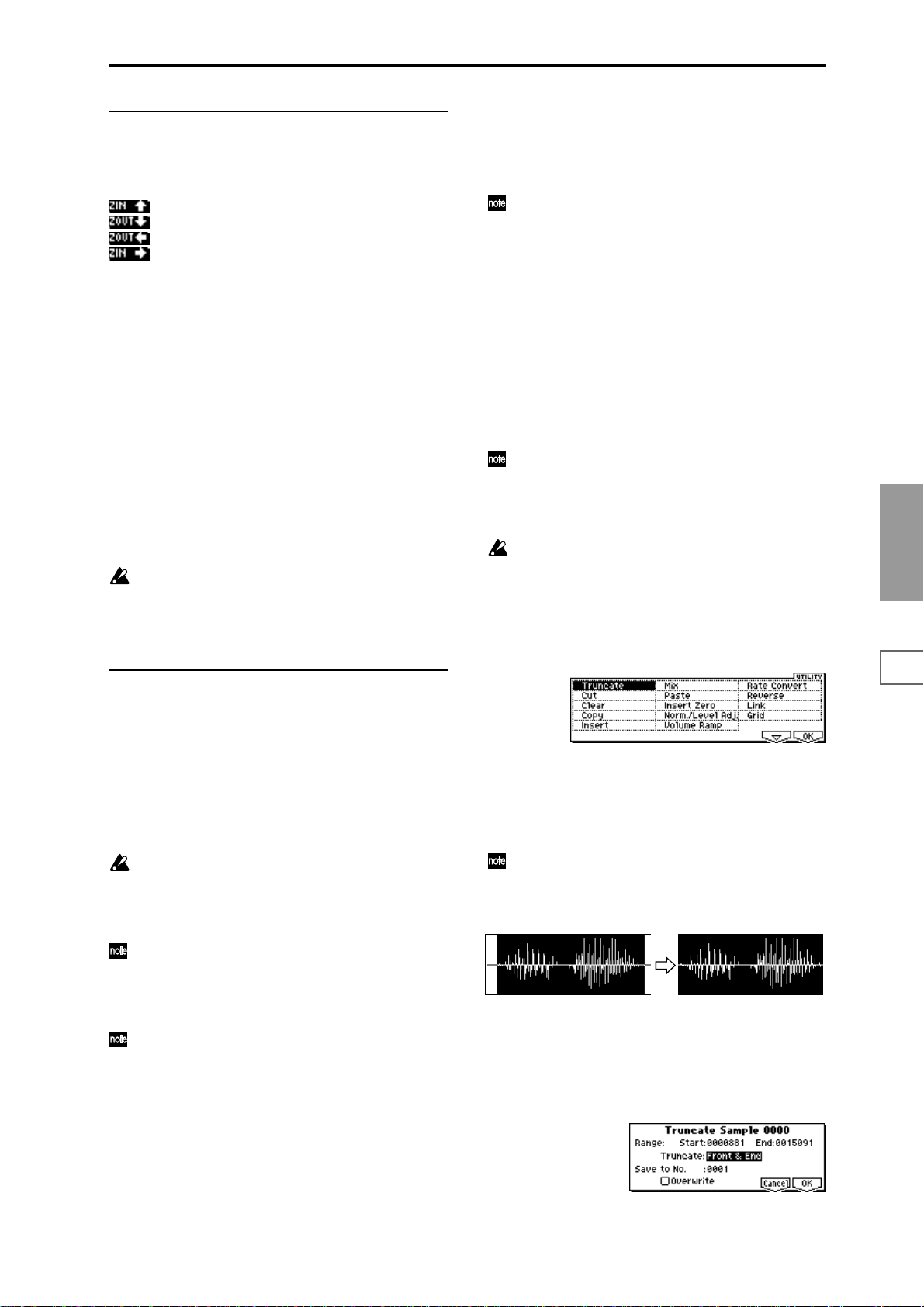
■ 2.1–2d: ZOOM
These buttons let you zoom-in and zoom-out the “sample
waveform display” in the horizontal axis (sample addresses)
or vertical axis (sample level).
: Press the [F4] key to zoom-in vertically.
: Press the [F5] key to zoom-out vertically.
: Press the [F6] key to zoom-out horizontally.
: Press the [F7] key to zoom-in horizontally.
If you continue holding each key, zoom-in/out will occur
repeatedly.
By zooming-in on the horizontal direction, you can move
from the overall display where the waveform is shown as a
solid line (1x magnification) to 2x or 4x magnification. (With
1x magnification, the display resolution of the LCD will be
the same as the resolution of the sample addresses. For
example if you change the sample address by one, the vertical line in the LCD that indicates the sample address will
move in steps of one pixel.) In the vertical axis, you can
zoom-in from 1x (full-range display) to 512x.
Zoom-In/zoom-out will occur starting at the “S (Edit Range
Start)” or “E (Edit Range End)” points you specify. (If a different parameter is selected when you zoom-in or -out, the
zoom-in/out will be based on the last-selected point. If you
re-select the “S (Edit Range Start)” or “E (Edit Range End)”
points when the display is zoomed in or out, the display
range will be adjusted so as to show the selected point.)
If the zoom ratio is low (1x or less), the “sample waveform display” may differ slightly from the displayed
waveform before and after waveform editing, but this
does not affect the playback sound. If this occurs, raising the zoom ratio will make the display accurate.
■ 2.1–2e: UTILITY
You can also use these commands if you wish to monomix a stereo sample and use it as a mono sample. However, be aware that once a sample has been mixed to
mono, it is no longer possible to return it to a stereo
sample.
The playback “S (Start)” (start address), “LpS (Loop
Start)” (loop start address), and “E (End)” (end address)
of the sample waveform data are specified in 3.1: Loop
Edit, Edit2. If the above parameters are within the
range of sample addresses deleted or moved by the
editing command, their addresses will automatically be
moved.
*1
: About “Overwrite”
When “Overwrite” is unchecked: When the command is
executed, the edited sample will be saved in a different sample number. The unedited sample will remain without
change.
When “Overwrite” is checked: When the command is executed, the edited sample will be overwritten onto the original sample (number). The original sample will be modified.
Normally, you will leave “Save to No.” at its default
setting, and execute without checking “Overwrite.”
When you execute, both the data before and after editing will be preserved, and the sample number of the
edited data will be assigned as the sample of that index.
“LpS (Loop Start)” and “E (End)” (3.1–2b) must be
located at least eight addresses apart. If as a result of
executing the Utility “Truncate,” “Cut,” or “Rate Convert” (2.1–2e), the “LpS (Loop Start)” and “E (End)”
would be separated by less than eight addresses, the
display will indicate “Sample length is shorter than
minimum.” Please set the “S (Edit Range Start)” and “E
(Edit Range End)” appropriately.
SMPL
1.1
2.13.14.15.15.27.2
Before using the utility commands “Truncate”–”Volume
Ramp” to edit sample waveform data, you must set “S (Edit
Range Start”) and “E (Edit Range End)” to specify the range
to be edited. Then select the desired utility menu command
and execute it.
The various utilities in this page can be selected from the
Edit2 page “UTILITY.” (They cannot be selected in the Edit1
page.) For the procedure of selecting a utility command,
refer to PROG 1.1–1d: UTILITY.
There is no compare function that lets you return the
edited result to the state before editing. If you wish to
preserve the unedited sample, uncheck the “Over-
*1
write”
item in the dialog box of each UITLITY menu
command before you execute.
For stereo samples, the L channel and R channel sam-
ples are edited simultaneously. If you wish to edit only
the L channel or R channel, select a mono multisample,
and select either the L channel or R channel sample for
editing.
If you “Copy” a mono sample into the buffer, and then
“Insert,” “Mix,” or “Paste” it to a stereo sample, the
data will be inserted, mixed, or pasted into both the L
and R sides. (The result will be that a stereo sample will
be created.)
If you “Copy” a stereo sample into the buffer, and then
“Insert,” “Mix,” or “Paste” it to a mono sample, the Land R-side data in the buffer will be mixed to mono,
and then inserted, mixed, or pasted. (The result will be
that a mono sample will be created.)
Truncate
This command deletes unwanted data that lies beyond the
“S (Edit Range Start)” and “E (Edit Range End).” Use this
command when you wish to delete silence at the beginning
or end of the waveform data.
If you wish to delete unneeded (unplayed) sample data
after setting the start address, loop start address, and
end address, use the Utility “Truncate” found in 3.1:
Loop Edit, Edit2 page.
1 Use “SMPL” (2.1–1a) to select the sample that you wish
to edit, and use “S (Edit Range Start)” and “E (Edit Range
End)” (2.1–1b) to specify the editing range.
You can press the [AUDITION] key to hear the portion
that will be left by the “Truncate” command.
2 Select “Truncate” to open the following dialog box.
85
Page 93
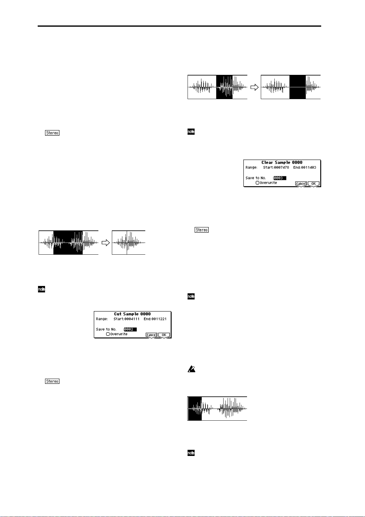
3 The editing range will be shown in Range “Start” and
“End.”
4 Use “Truncate” to select the portion that will be deleted.
Front & End: The sample data that lies before the “S (Edit
Range Start)” and after the “E (Edit Range End)” will be
deleted.
Front: The sample data that lies before the “S (Edit Range
Start)” will be deleted.
End: The sample data that lies after the “E (Edit Range
End)” will be deleted.
5 In “Save to No.,” specify the save destination sample
number. By default, an unused sample number will be
selected. If you have checked “Overwrite,” this cannot be
set.
For a stereo sample, “Save to No.(L)” and “(R)”
will be displayed. Specify the save destination sample
number for the L channel and R channel respectively.
6 If you wish to delete the original sample data and over-
write it with the edited sample data, check “Overwrite”.
Normally, you will leave “Save to No.” at its default setting, and execute without checking “Overwrite.” (
“*”: About “Overwrite”)
7 To execute the Truncate command, press the [F8] (“OK”)
key. To cancel, press the [F7] (“Cancel”) key.
☞p.85
Cut
This command deletes the data between the “S (Edit Range
Start)” and “E (Edit Range End).” Sample data located after
the deleted portion will be moved forward.
1 Use “SMPL” (2.1–1a) to select the sample that you wish
to edit, and use “S (Edit Range Start)” and “E (Edit Range
End)” (2.1–1b) to specify the editing range.
You can press the [AUDITION] key to hear the portion
that will be deleted by the “Cut” command.
2 Select “Cut” to open the following dialog box.
Clear
This command converts the data between “S (Edit Range
Start)” and “E (Edit Range End)” to zero values. Sample
data before and after the edited range will not move.
1 Use “SMPL” (2.1–1a) to select the sample that you wish
to edit, and use “S (Edit Range Start)” and “E (Edit Range
End)” (2.1–1b) to specify the editing range.
You can press the [AUDITION] key to hear the portion
that will be changed to zero-level by the “Clear” command.
2 Select “Clear” to open the following dialog box.
3 The range to be edited is shown by Range “Start” and
“End.”
4 In “Save to No.,” specify the save destination sample
number. By default, an unused sample number will be
selected. If you have checked “Overwrite,” this cannot be
set.
For a stereo sample, “Save to No.(L)” and “(R)”
will be displayed. Specify the save destination sample
number for the L channel and R channel respectively.
5 If you wish to delete the original sample data and over-
write it with the edited sample data, check “Overwrite”.
Normally, you will leave “Save to No.” at its default setting, and execute without checking “Overwrite.” (
“*”: About “Overwrite”)
6 To execute the Clear command, press the [F8] (“OK”)
key. To cancel, press the [F7] (“Cancel”) key.
Normally you will leave “Save to No.” at the default
setting, and execute without checking “Overwrite.”
When you execute, the original data and the edited data
will both be preserved, and the sample number after
editing will be assigned to the sample of the index.
☞p.85
3 The range to be edited is shown by Range “Start” and
“End.”
4 In “Save to No.,” specify the save destination sample
number. By default, an unused sample number will be
selected. If you have checked “Overwrite,” this cannot be
set.
For a stereo sample, “Save to No.(L)” and “(R)”
will be displayed. Specify the save destination sample
number for the L channel and R channel respectively.
5 If you wish to delete the original sample data and over-
write it with the edited sample data, check “Overwrite”.
Normally, you will leave “Save to No.” at its default setting, and execute without checking “Overwrite.” (
“*”: About “Overwrite”)
6 To execute the Cut command, press the [F8] (“OK”) key.
To cancel, press the [F7] (“Cancel”) key.
86
Copy
This command copies the sample data from the area
between “S (Edit Range Start)” and “E (Edit Range End)”
into the sample data buffer. This data can then be used by
the “Insert,” “Mix” or “Paste” commands.
When “Copy” is executed, the data that is loaded into the
buffer simply references the data of the original sample.
After using “Copy,” do not delete the copy source sample
until you “Insert,” “Mix” or “Paste” the copied data.
☞p.85
1 Use “SMPL” (2.1–1a) to select the sample that you wish
to edit, and use “S (Edit Range Start)” and “E (Edit Range
End)” (2.1–1b) to specify the editing range.
You can press the [AUDITION] key to hear the portion
that will be copied by the “Copy” command.
Page 94

2 Select “Copy” to open the following dialog box.
3 The range to be copied is shown by Range “Start” and
“End.”
4 To execute the Copy command, press the [F8] (“OK”)
key. To cancel, press the [F7] (“Cancel”) key.
Insert
When you execute the “Insert” command, the sample data
that was loaded into the buffer by the “Copy” command
will be inserted starting at the “S (Edit Range Start)”
address. The data that had been at that location will be
moved backward.
From the
buffer
1 Use “SMPL” (2.1–1a) to select the sample that you wish
to edit, and set “S (Edit Range Start)” to specify the starting address. The “E (Edit Range End)” (2.1–1b) setting is
ignored.
2 Select “Insert” to open the following dialog box.
3 To “Start” will indicate the starting address at which the
data will be inserted.
4 In “Save to No.,” specify the save destination sample
number. By default, an unused sample number will be
selected. If you have checked “Overwrite,” this cannot be
set.
For a stereo sample, “Save to No.(L)” and “(R)”
will be displayed. Specify the save destination sample
number for the L channel and R channel respectively.
5 If you wish to delete the original sample data and over-
write it with the edited sample data, check “Overwrite”.
Normally, you will leave “Save to No.” at its default setting, and execute without checking “Overwrite.” (
“*”: About “Overwrite”)
6 To execute the “Insert” command, press the [F8] (“OK”)
key. To cancel, press the [F7] (“Cancel”) key.
If the buffer into which data was placed by the “Copy”
command contains no data, the display will indicate
“Source sample is empty.”
☞p.85
2 Select “Mix” to open the following dialog box.
3 To “Start” will indicate the starting address at which the
data will be mixed.
4 In “Save to No.,” specify the save destination sample
number. By default, an unused sample number will be
selected. If you have checked “Overwrite,” this cannot be
set.
For a stereo sample, “Save to No.(L)” and “(R)”
will be displayed. Specify the save destination sample
number for the L channel and R channel respectively.
5 If you wish to delete the original sample data and over-
write it with the edited sample data, check “Overwrite”.
Normally, you will leave “Save to No.” at its default setting, and execute without checking “Overwrite.” (
☞p.85
“*”: About “Overwrite”)
6 To execute the “Mix” command, press the [F8] (“OK”)
key. To cancel, press the [F7] (“Cancel”) key.
If the buffer into which data was placed by the “Copy”
command contains no data, the display will indicate
“Source sample is empty.”
Paste
Beginning at the “S (Edit Range Start)” address, this command places the sample data that was loaded into the buffer
by “Copy” command. The original data will be deleted, and
overwritten by the sample data from the buffer . You can also
place sample data into a blank sample. This is convenient
when you wish to “Copy” part of a sample and create a new
sample based on it.
Pasting to a sample that contains sample data
From the
buffer
1 Use “SMPL” (2.1–1a) to select the sample that you wish
to edit, and set “S (Edit Range Start)” (2.1–1b) to specify
the starting address. The “E (Edit Range End)”setting is
ignored.
2 Select “Paste” to open the following dialog box.
SMPL
1.1
2.13.14.15.15.27.2
Mix
When you execute the “Mix” command, the sample that was
loaded into the buffer by the “Copy” command will be
mixed with the selected sample data. The data will be mixed
starting at the “S (Edit Range Start)” address.
1 Use “SMPL” (2.1–1a) to select the sample that you wish
to edit, and set “S (Edit Range Start)” (2.1–1b) to specify
the starting address. The “E (Edit Range End)” setting is
ignored.
From the
buffer
3 To “Start” will indicate the starting address at which the
data will be pasted.
4 In “Save to No.,” specify the save destination sample
number. By default, an unused sample number will be
selected. If you have checked “Overwrite,” this cannot be
set.
For a stereo sample, “Save to No.(L)” and “(R)”
will be displayed. Specify the save destination sample
number for the L channel and R channel respectively.
5 If you wish to delete the original sample data and over-
write it with the edited sample data, check “Overwrite”.
Normally, you will leave “Save to No.” at its default setting, and execute without checking “Overwrite.” (
☞p.85
“*”: About “Overwrite”)
6 To execute the “Paste” command, press the [F8] (“OK”)
key. To cancel, press the [F7] (“Cancel”) key.
87
Page 95

If the buffer into which data was placed by the “Copy”
command contains no data, the display will indicate
“Source sample is empty.”
Pasting to a sample that contains no sample data
1 Select the vacant sample number that you wish to paste.
If you select ----:---No Assign---- for “Sample” and then
access the dialog box for this command, a vacant sample
number will be selected automatically.
The “S (Edit Start Range)” and “E (Edit Range End)”
(2.1–1b) settings will be ignored, and will have no
effect. The beginning of the sample will be placed at
address 0.
2 Select “Paste” to open the following dialog box.
Norm./Level Adj. (Normalize/Level Adjust)
This command uniformly modifies the data values (volume)
of the data between the “S (Edit Range Start)” and “E (Edit
Range End).” “Normalize” will amplify the level of the sample data as far as possible without allowing it to clip (distort). If the level of the sampled data is too low, you can
execute this command to increase the dynamic range.
“Level” allows you to raise or lower the level as desired.
Normalize
Level Adjust –12dB
3 In “Save to No.,” specify the save destination sample
number. If you wish to change it, re-specify the desired
number.
If the sample data loaded into the buffer by
“Copy” is stereo, the display will indicate “Save to
No.(L)” and “(R).” Specify the save destination sample
number for the L channel and the R channel.
4 To execute the “Paste” command, press the [F8] (“OK”)
key. To cancel without executing, press the [F7] (“Cancel”) key.
Insert Zero
This command inserts zero-level sample data (silence),
beginning at the “S (Edit Range Start)” address. The data
that previously occupied that location will be moved backward.
Size
1 Use “SMPL” (2.1–1a) to select the sample that you wish
to edit, and set “S (Edit Range Start)” (2.1–1b) to specify
the starting address. The “E (Edit Range End)” setting is
ignored.
2 Select “Insert Zero” to open the following dialog box.
3 To “Start” will indicate the starting address at which the
data will be inserted.
4 In “Size,” specify the length of the data that will be
inserted.
5 In “Save to No.,” specify the save destination sample
number. By default, an unused sample number will be
selected. If you have checked “Overwrite,” this cannot be
set.
For a stereo sample, “Save to No.(L)” and “(R)”
will be displayed. Specify the save destination sample
number for the L channel and R channel respectively.
6 If you wish to delete the original sample data and over-
write it with the edited sample data, check “Overwrite”.
Normally, you will leave “Save to No.” at its default setting, and execute without checking “Overwrite.” (
“*”: About “Overwrite”)
7 To execute the “Insert Zero” command, press the [F8]
(“OK”) key. To cancel, press the [F7] (“Cancel”) key.
☞p.85
1 Use “SMPL” (2.1–1a) to select the sample that you wish
to edit, and use “S (Edit Range Start)” and “E (Edit Range
End)” (2.1–1b) to specify the editing range.
You can press the [AUDITION] key to hear the portion
that will be normalized or level-adjusted.
2 Select “Norm./Level Adj.” to open the following dialog
box.
3 The range to be edited is shown by Range “Start” and
“End.”
4 If you check “Normalize” and execute, the data will be
normalized. In this case, the “Level” setting will be
ignored.
If you wish to specify “Level” to modify the level of the
sample data, do not check “Normalize.”
Each increase of +6 dB will approximately double the
height of the waveform shown in the LCD. +12 dB will
be an increase of approximately 4X, and +18 dB will be
approximately 8X. Conversely, each decrease of –6 dB
will halve the level, so that –6 dB will be 1/2X and –12
dB will be approximately 1/4X. Executing the "Level"
command with positive (+) settings may cause the
sound to clip (i.e., distort at the point that amplification
beyond the maximum level is impossible). Once the
sample data has been boosted beyond the clipping
point, re-executing this command with negative (–) settings of “Level” will simply lower the overall level of
the clipped signal –the waveform will remain distorted.
Also, if executing “Level” with negative (–) settings
causes any portion of the sample data to reach a zero
level, the zero data will not return to its original state
even if you re-execute “Level” with positive (+) settings.
5 In “Save to No.,” specify the save destination sample
number. By default, an unused sample number will be
selected. If you have checked “Overwrite,” this cannot be
set.
For a stereo sample, “Save to No.(L)” and “(R)”
will be displayed. Specify the save destination sample
number for the L channel and R channel respectively.
6 If you wish to delete the original sample data and over-
write it with the edited sample data, check “Overwrite”.
Normally, you will leave “Save to No.” at its default set-
88
Page 96
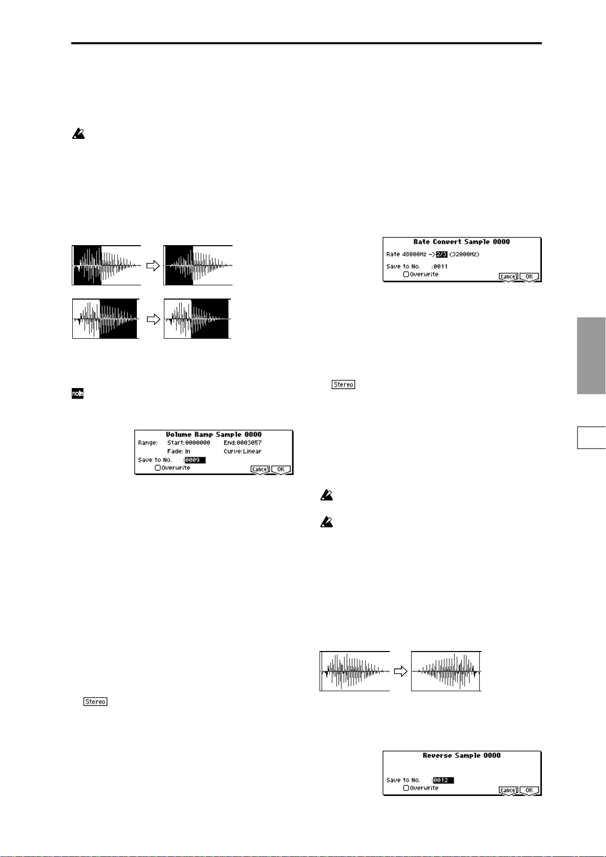
ting, and execute without checking “Overwrite.” (☞p.85
“*”: About “Overwrite”)
7 To execute the Normalize/Level Adjust command, press
the [F8] (“OK”) key. To cancel, press the [F7] (“Cancel”)
key.
Be aware that if sample data of an extremely low level
is normalized, any noise included in the sample will
also be amplified.
Volume Ramp
This command modifies the data values (volume) between
the “S (Edit Range Start)” and “E (Edit Range End).” Y ou
can make the volume gradually increase (Fade In) or
decrease (Fade Out) from the “S (Edit Range Start)” to the “E
(Edit Range End).”
Fade In
Rate Convert
This command lowers the sampling rate (frequency) of the
sampled data by 2/3, 1/2, 1/3, 1/4, or 1/6. The sampling
frequency of input is fixed at 48 kHz, but you can use this
command to create “down-sampling” effects. The sample
data is thinned to convert it into sample data of a lower sampling frequency.
The “Rate Convert” command is always executed on all
waveform data of the selected sample, regardless of the “S
(Edit Range Start)” and “E (Edit Range End)” (2.1–1b) settings.
1 Use “SMPL” (2.1–1a) to select the sample that you wish
to edit.
2 In the Edit2 page “UTILITY,” choose “Rate Convert” to
open the following dialog box.
Fade Out
1 Use “SMPL” (2.1–1a) to select the sample that you wish
to edit, and use “S (Edit Range Start)” and “E (Edit Range
End)” (2.1–1b) to specify the editing range.
You can press the [AUDITION] key to hear the portion
on which “Volume Ramp” will be executed.
2 Select “Volume Ramp” to open the following dialog box.
3 The range to be edited is shown by Range “Start” and
“End.”
4 Use “Fade” to select the type of volume ramp.
In: The volume will be zero at Range “Start,” and will
gradually increase toward the “End” volume.
Out: The volume will gradually decrease from the Range
“Start” volume, and will reach zero at the “End” volume.
5 In “Curve,” specify the way in which the volume will
change.
Linear: The volume will change linearly. For normal
fade-in or fade-out, select Linear.
Power: The volume will change non-linearly. When you
use “Mix” (2.1–2e) to combine a faded-in waveform with
a different faded-out waveform (i.e., crossfade), using a
Linear fade-in/out may produce an impression that the
volume has dropped in the middle of the curve. In such
cases, use Power to perform the fade-in/out.
6 In “Save to No.,” specify the save destination sample
number. By default, an unused sample number will be
selected. If you have checked “Overwrite,” this cannot be
set.
For a stereo sample, “Save to No.(L)” and “(R)”
will be displayed. Specify the save destination sample
number for the L channel and R channel respectively.
7 If you wish to delete the original sample data and over-
write it with the edited sample data, check “Overwrite”.
Normally, you will leave “Save to No.” at its default setting, and execute without checking “Overwrite.” (
“*”: About “Overwrite”)
8 To execute the Volume Ramp command, press the [F8]
(“OK”) key. To cancel, press the [F7] (“Cancel”) key.
☞p.85
3 The sampling rate of the selected sample is shown at the
right of “Rate.” At the right of the “->” you can select the
desired amount of the sampling rate conversion: 2/3, 1/2,
1/3, 1/4, 1/6. The sampling rate following conversion will
be displayed.
4 In “Save to No.,” specify the save destination sample
number. By default, an unused sample number will be
selected. If you have checked “Overwrite,” this cannot be
set.
For a stereo sample, “Save to No.(L)” and “(R)”
will be displayed. Specify the save destination sample
number for the L channel and R channel respectively.
5 If you wish to delete the original sample data and over-
write it with the edited sample data, check “Overwrite”.
Normally, you will leave “Save to No.” at its default setting, and execute without checking “Overwrite.” (
“*”: About “Overwrite”)
6 To execute the Insert Zero command, press the [F8]
(“OK”) key. To cancel, press the [F7] (“Cancel”) key.
This command cannot be executed on a sample whose
sampling rate is less than 11.025 kHz.
Stereo samples must have the same sampling rate.
Although it is possible to select mono multisamples for
-L and -R and convert their sampling rate separately,
they can no longer be handled as a stereo sample in this
case.
☞p.85
Reverse
This command reverses the sample data (i.e., exchanges the
beginning and end).
The “Reverse” command is always executed on all waveform data of the selected sample, regardless of the “S (Edit
Range Start)” and “E (Edit Range End)” (2.1–1b) settings.
1 Use “SMPL” (2.1–1a) to select the sample that you wish
to edit.
2 In the Edit2 page “UTILITY,” choose “Reverse” to open
the following dialog box.
SMPL
1.1
2.13.14.15.15.27.2
89
Page 97
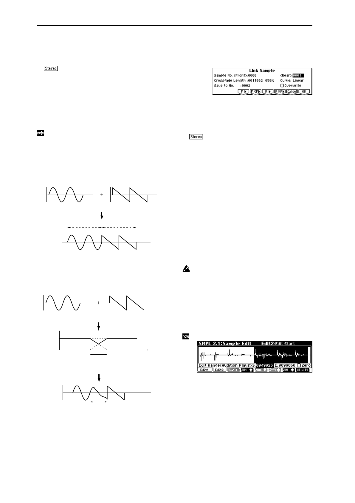
3 In “Save to No.,” specify the save destination sample
number. By default, an unused sample number will be
selected. If you have checked “Overwrite,” this cannot be
set.
For a stereo sample, “Save to No.(L)” and “(R)”
will be displayed. Specify the save destination sample
number for the L channel and R channel respectively.
4 If you wish to delete the original sample data and over-
write it with the edited sample data, check “Overwrite”.
Normally, you will leave “Save to No.” at its default setting, and execute without checking “Overwrite.” (
☞p.85
“*”: About “Overwrite”)
5 To execute the Reverse command, press the [F8] (“OK”)
key. To cancel, press the [F7] (“Cancel”) key.
When you execute this command, the entire sample
data will be rewritten backward. By using 3.1: Loop
Edit “Rev (Reverse)” (3.1–1b), you can reverse the playback direction without affecting the sample data itself.
Link
This command connects the currently selected sample with
another sample.
SOUND A SOUND B
LINK
SOUND A
The volume of the two samples can be changed gradually at
the transition to gradually mix the samples with each other.
This is called crossfade, and can be used to produce a natural-sounding transition between the two sounds.
SOUNDA SOUNDB
CROSSFADELINK
Volume
SOUND B
1 Use “SMPL” (2.1–1a) to select the sample that will be
placed in front by the Link command.
2 In the Edit2 page “UTILITY,” choose “Link” to open the
following dialog box.
3 The sample number selected for “Sample No. (Front)”
will be displayed. When the command is executed, this
sample will be placed in front.
While you hold down the [F3] (“F®”) key, the entire
sample will play back. After the entire sample has played
back, it will stop.
If you select one side of a stereo sample, it will
automatically be detected as a stereo sample, and the
other side of the sample will also be processed by the
Link command.
If the “Front” Sample is mono and the Rear Sample is stereo, the L and R of the “Rear” Sample will be mixed to
mono before linking.
If the “Front” Sample is stereo and the “Rear” Sample is
mono, the identical sample will be placed in L and R of
the “Rear” Sample before linking.
4 Use “Sample No. (Rear)” to select the sample number
that will be linked. When the command is executed, this
sample will be placed in back.
While you hold down the [F5] (“R®”) key, the entire
sample will play back. After the entire sample has played
back, it will stop.
5 In “Crossfade Length,” specify the length over which the
crossfade will occur. If you specify a % value, the proportion in relation to the entire “Front” Sample will be calculated automatically . If you specify 50%, the last half of the
“Front” Sample will crossfaded.
If the rear sample is short, the “Crossfade Length” cannot be set any longer than the length of the “Rear ”sam-
ple. In this case, it will not be possible to specify a value
up to 100%.
If you set “Crossfade Length” to other than 0, “F XF®”
and “R XF®” will be displayed. By holding down one of
these buttons, you can play back just the crossfaded portion of the front or rear sample. Playback will stop after
the length specified by “Crossfade Length.” If you do not
wish to crossfade, set this to 0.
SOUNDA
Crossfaded portion
(Sound A gradually diminishes,
and sound B gradually increases)
Crossfaded portion
(This is called the “Crossfade
Length”)
SOUNDB
Time
“Link” will be executed for all of the selected sample data,
regardless of the “S (Edit Range Start)” and “E (Edit Range
End)” (2.1–1b) settings.
90
After selecting a sample in step
1, you can set “S (Edit
Range Start)” and specify the beginning of the crossfade
while viewing the waveform. Set “E (Edit Range End)” to
the end of the sample. If you specify these, “Crossfade
Length” will indicate the length determined by “S (Edit
Range Start)” and “E (Edit Range End).”
6 In “Curve,” specify how you want the volume to change
in the crossfaded portion.
Linear: The volume will change linearly.
Power: The volume will change non-linearly. In some
cases, “Linear” may sound as though the volume diminishes in the middle of the curve. If this occurs, use
“Power.”
Page 98
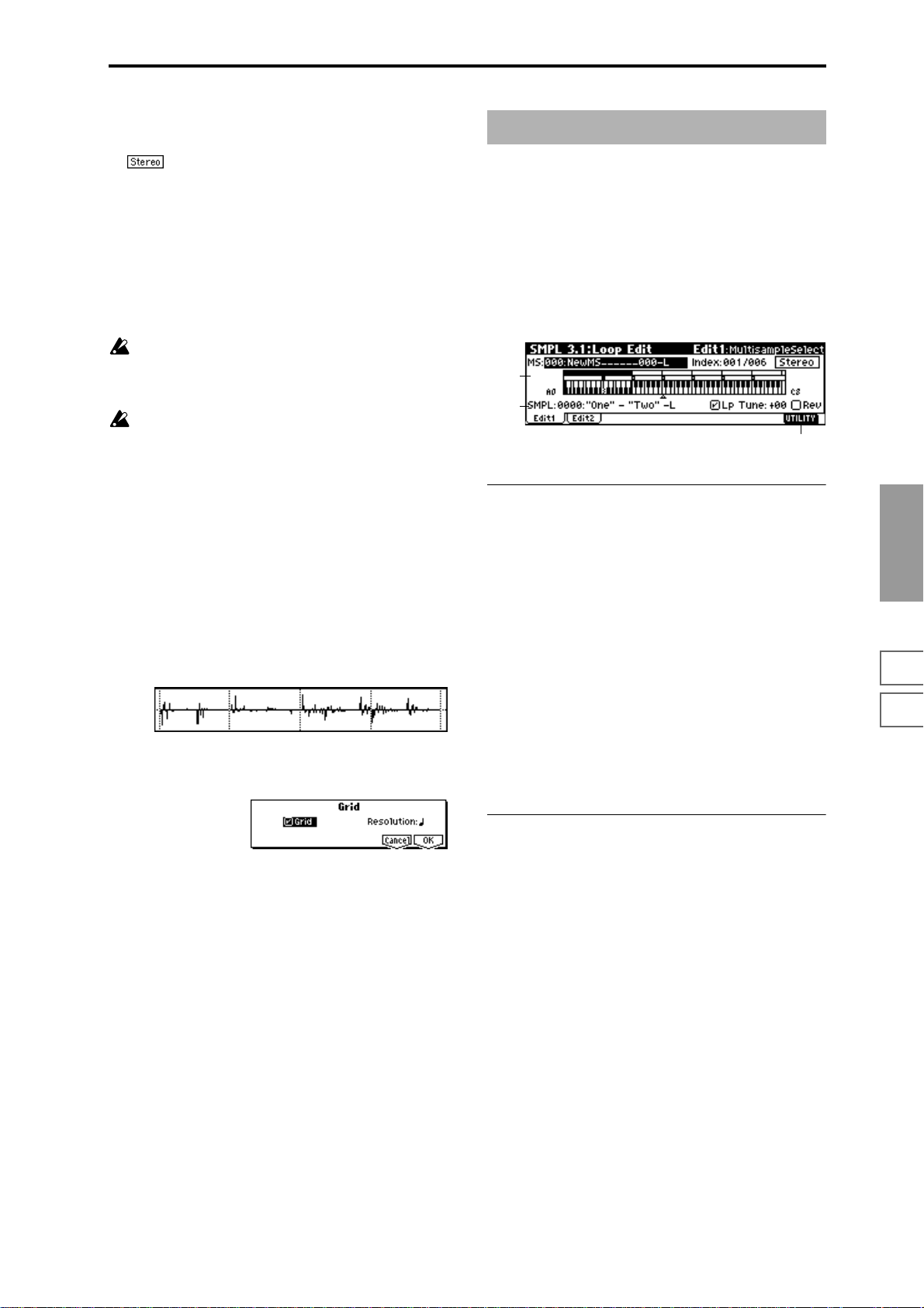
7 In “Save to No.,” specify the save destination sample
number. An unused sample number will be selected by
default. If “Overwrite” is checked, this cannot be set.
In the case of a stereo sample, “Save to No.(L)”
and “(R)” will be displayed. You must specify the save
destination sample for both the L channel and R channel.
8 If you wish to delete the original sample data and over-
write it with the edited sample data, check “Overwrite”.
Normally, you will leave “Save to No.” at its default setting, and execute without checking “Overwrite.” (
“*”: About “Overwrite”)
9 To execute the Link command, press the [F8] (“OK”) key.
To cancel without executing, press the [F7] (“Cancel”)
key.
If you link samples of different sampling rates (such as
created by “Rate Convert”
sample will have the sampling rate of the “Front” sample.
One vacant sample is used in order to execute Link. Be
aware that if there are no vacant samples, an error will
occur.
☞2.1–2e), the newly created
☞p.85
Grid
This command displays a grid in the “sample waveform display.”If you check “Grid” and execute, vertical dotted lines
will appear in the “sample waveform display,” according to
the resolution and tempo specified by “Resolution” and “
(Grid Tempo)” (2.1–2b). You can use this when cutting or
editing sample data according to BPM values or beats. The
vertical dotted lines are displayed starting at the address
specified by the “S (Start)” (when Loop Off) or “LpS (Loop
Start)” (when Loop On) settings of the 3.1: Loop Edit, Edit 2
page, and show the timing when the currently selected key
(displayed in gray) is played. (
1a)
1 Use “SMPL” (2.1–1a) to select a sample.
2 In the Edit2 page “UTILITY,” choose “Grid” to open the
following dialog box.
☞“Keyboard & Index” 1.1–
SMPL 3.1: Loop Edit
Here you can specify the portion of the sample that will be
played back, set sample parameters for playback loop etc.,
and edit the sample. Sample parameters that were loaded
into internal sampling memory in Disk mode can also be
edited in the same way. You can make detailed edits in single-sample steps while watching the sample waveform display.
3.1–1: Edit1
3.1–1a
3.1–1b
3.1–1c
3.1–1a: MS, Index, Keyboard&Index
MS (Multisample Select) [000...999]
Select s the multisample whose loop and other sample
parameters you wish to edit (
Index [xxx (001...128)/yyy (001...128)]
Select s the index whose loop and other sample parameters
you wish to edit. Your edits will apply to the sample of the
index selected here, and the waveform will appear in the
“sample waveform display” (
To select an index, hold down the [ENTER] key and play a
note on the keyboard of a connected MIDI instrument. The
index that includes the note you played will be selected. The
specified key will be the base key, and will be displayed in
gray in “Keyboard & Index.”
Keyboard & Index
(☞1.1–1a)
☞1.1–1a).
☞1.1–1a).
SMPL
1.1
2.13.14.15.15.27.2
3 Check “Grid” to turn on the grid display.
4 Set “Resolution” to the desired grid interval – . The
spacing of the grid will be determined by this setting and
by “ (Grid Tempo)” (2.1–2b).
5 To execute the setting, press the [F8] (“OK”) key. To can-
cel without executing, press the [F7] (“Cancel”) key.
3.1–1b: SMPL, Lp, Tune, Rev
SMPL (Sample Select)
[----: ---No Assign----, 0000...3999]
This shows the sample number and name, and the range of
the selected index. If you change “SMPL,” the sample you
specify will be assigned to this index. The sample you select
here will appear in the “sample waveform display” (
1a).
☞1.1–
Lp (Loop) [Off, On]
Specify whether the sample will be looped.
On (Checked): The sample will play back repeatedly from
“LpS (Loop Start)” to “E (End)”; i.e., “S (Start)” → “E (End)”
→ “LpS (Loop Start)” → “E (End)” → “LpS (Loop Start)” →
... (
☞3.1–2b)
Off (Unchecked): The sample will playback once (“one-
shot”) from “S (Start)” → “E (End).”
This will be checked automatically if “Auto Loop” (1.1–3c)
was checked when you sampled.
91
Page 99
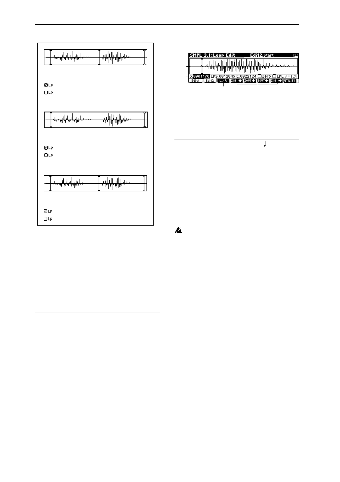
3.1–2: Edit2
"One"
Start Loop Start End
"One" - "Two" - "Two" - "Two" - ...
"One" - "Two"
"One"
Start
Loop Start
"One" - "Two" - "One" - "Two" - "One" - "Two" - ...
"One" - "Two"
"One"
Loop Start
"Two" - "One" - "Two" - "One" - "Two" - "One" -...
"Two"
Start
"Two"
"Two"
End
"Two"
End
Tune (Loop Tune) [–99...+99]
When looping is on (“Lp” is checked), you can adjust the
playback pitch of the loop from “S (Start)” to “E (End)” over
a range of ±99 cents. When you loop data that was sampled
from a musical instrument etc., the pitch of the looped portion may sometimes be incorrect. Use this parameter to compensate for such cases.
Rev (Reverse) [Off, On]
On (Checked): The sample will be played backward, from
“E (End)” (end address) to “LpS (Loop Start)” (loop start
address).
■ 3.1–1c: UTILITY
☞“Delete SMPL,” “Copy SMPL,” “Move SMPL,” “Rename
SMPL,” “SMPL To Stereo,” “Delete MS,” “Copy MS,”
“Move MS,” “Rename MS,” “MS To Stereo/MS To
Mono,” “Conv. To Prog,” “Keyboard Disp.” (1.1–3g)
3.1–2a
3.1–2b
3.1–2c 3.1–2d
3.1–2e
3.1–2a: Sample waveform display
Sample waveform display
The waveform of the “SMPL (Sample)” is displayed here
(
☞2.1–2a).
3.1–2b: Sample Address, Zero, LpL,
S (Start) [0000000...]
Specifies the starting address for sample playback. This
value is in units of a sample address.
LpS (Loop Start) [0000000...]
Specifies the loop start address for sample playback. This is
valid when Loop is On. This value is in units of a sample
address, (
☞“S.Ofs” PROG 2.1–2b).
E (End) [0000000...]
Specifies the ending address for sample playback. This value
is in units of a sample address.
Loop Start Address and End Address must be located at
least eight addresses apart. This setting will be applied
automatically when you set the addresses.
Zero (Use Zero) [Off, On]
On (Checked): “S (Start),” “E (End),” and “LpS (Loop Start)”
parameters can be set only at “zero-cross” addresses where
the waveform level crosses ±0 (the center line of the waveform display). (
Off (Unchecked): “S,” “E,” and “LpS” can be set in steps of
1. This is the normal setting.
☞2.1–2b)
LpL (Loop Lock) [Off, On]
This fixes the length of the loop being edited.
On (Checked): When the “LpS (Loop Start)” or “End”
address is edited, the “E (End)” or “LpS” will be automatically adjusted so that the distance between “LpS” and “E
(End)” (i.e., the loop length) does not change. This is convenient when you are creating a rhythm loop to match a specific tempo.
92
(Grid Tempo) [040...480(BPM)]
This displays vertical dotted lines in the “sample waveform
display” to indicate the resolution and tempo. Use this when
you wish to cut or edit the sample data based on a BPM
value or beat.
The grid will be displayed if you check and execute the
“Grid” (2.1–2e/3.1–2e) utility command. The spacing of the
grid is determined by the “Resolution” setting of the “Grid”
page menu command, relative to the playback pitch of the
base key (the key displayed in gray in “Keyboard & Index”
1.1–1a) at the tempo value you specify here. The grid will
begin at the “S (Start)” address (when looping is off) or at
the “LpS (Loop Start)” address (when looping is on). This
parameter can also be set from the 2.1: Sample Edit, Edit2
page.
Page 100

This is not related to the setting of the REALTIME
CONTROLS C-mode [TEMPO] knob.
■ 3.1–2c: L/R
This is valid only if a stereo sample is selected.
It switches the display between the L channel and R channel
of a stereo sample. (
■ 3.1–2d: ZOOM
These buttons let you zoom-in and zoom-out the “sample
waveform display” in the horizontal axis (sample addresses)
or vertical axis (sample level). (
■ 3.1–2e: UTILITY
For details on selecting utility commands, refer to “2.1–2e:
UTILITY.”
☞“Grid” (2.1–2e)
☞2.1–2c)
☞2.1–2d)
Truncate
This command deletes unwanted data that lies outside of
the “S (Start),” “LpS (Loop Start ),” and “E (End )” (3.1–2d).
After setting the start address, loop start address, and end
address of the sample, use this command to delete
unwanted sample data.
1 Use “SMPL” (3.1–1b) to select the sample that you wish
to edit, and use “S (Start)” or “LpS (Loop Start)” and “E
(End)” (3.1–2b) to specify the editing range.
You can press the [AUDITION] key to hear the portion
that will be left by the “Truncate” command.
2 In the Edit2 page “UTILITY,” choose “Truncate” to open
the following dialog box.
6 If you wish to delete the original sample data and over-
write it with the edited sample data, check “Overwrite”.
Normally, you will leave “Save to No.” at its default setting, and execute without checking “Overwrite.” (
“*”: About “Overwrite”)
7 To execute the Truncate command, press the [F8] (“OK”)
key. To cancel, press the [F7] (“Cancel”) key.
☞p.85
Time Slice
Time Slice detects the attacks (e.g., kick and snare) within a
rhythm loop sample (a sample that loops a drum pattern,
etc.), and automatically divides the sample into individual
percussion instrument notes. The divided percussion instrument notes will be created as individual samples, and automatically assigned as a multisample and program. Song
performance data corresponding to the divided samples will
also be created, so that in Multi mode you can adjust the
tempo of the song to change only the tempo of the rhythm
loop without affecting the pitch. Pattern data and RPPR
assignments for the sliced samples can also be created automatically. The performance data that is created will use
notes D2 and above, corresponding to the newly created
samples of individual percussion instruments.
By means of this function in Multi mode RPPR, multiple
rhythm loop samples of differing tempo can be matched to
the desired tempo without changing their pitch (
75). You can also use the keyboard of a connected MIDI
device to start/stop multiple rhythm loop samples, or use
the REALTIME CONTROLS C-mode [TEMPO] knob to
modify the tempo in realtime.
In addition to changing only the tempo of the rhythm loop
without affecting the pitch, this makes it possible for you to
exchange note numbers, to change the timing, or to edit the
sequence data to freely recreate the original rhythm loop.
The pattern data you create can also be written as SMF data,
allowing you to send note data from an external MIDI
sequencer etc. to the TRITON-Rack to play it.
This command can also be executed on stereo samples.
As an alternative to Utility “Time Slice,” the Utility
“Time Stretch” (3.1–2e) command can also be used to
change the tempo without affecting the pitch of a
rhythm loop sample etc. “Time Stretch” is suitable
when you do not need to divide the sample or to create
multi playback data for the divided sample.
☞BG p.74,
SMPL
1.1
2.13.14.15.15.27.2
3 Range “Start” and “End” will show the range of data that
will be edited.
4 Use “Trancate” to select the portion that will be deleted.
Front & End: The sample data that lies before the “Start”
and after the “End” will be deleted.
Front: The sample data that lies before the “Start” (start
address) will be deleted.
End: The sample data that lies after the “End” (end
address) will be deleted.
5 In “Save to No.,” specify the save destination sample
number. By default, an unused sample number will be
selected.
For a stereo sample, “Save to No.(L), (R)” will be
displayed. Specify the save destination sample number
for the L channel and R channel respectively.
93
 Loading...