

Page 1
3E
Page 2

ii
To ensure long, trouble-free operation,
please read this manual carefully.
Precautions
Location
Using the unit in the following locations can result
in a malfunction.
• In direct sunlight
• Locations of extreme temperature or humidity
• Excessively dusty or dirty locations
• Locations of excessive vibration
Power supply
Please connect the designated AC/AC power supply to an AC outlet of the correct voltage. Do not
connect it to an AC outlet of voltage other than that
for which your unit is intended.
Interference with other electrical devices
This product contains a microcomputer. Radios and
televisions placed nearby may experience reception
interference. Operate this unit at a suitable distance
from radios and televisions.
Handling
To avoid breakage, do not apply excessive force to
the switches or controls.
Care
If the exterior becomes dirty, wipe it with a clean,
dry cloth. Do not use liquid cleaners such as benzene or thinner, or cleaning compounds or flammable polishes.
THE FCC REGULATION WARNING (for U.S.A.)
This equipment has been tested and found to comply with the
limits for a Class B digital device, pursuant to Part 15 of the FCC
Rules. These limits are designed to provide reasonable protection against harmful interference in a residential installation. This
equipment generates, uses, and can radiate radio frequency
energy and, if not installed and used in accordance with the
instructions, may cause harmful interference to radio communications. Ho we ver, there is no guarantee that interference will not
occur in a particular installation. If this equipment does cause
harmful interference to radio or television reception, which can
be determined by turning the equipment off and on, the user is
encouraged to try to correct the interference by one or more of
the following measures:
• Reorient or relocate the receiving antenna.
• Increase the separation between the equipment and receiver.
• Connect the equipment into an outlet on a circuit different
from that to which the receiver is connected.
• Consult the dealer or an experienced radio/TV technician for
help.
Unauthorized changes or modification to this system can void
the user’s authority to operate this equipment.
CE mark for European Harmonized Standards
CE mark which is attached to our company’s products of AC
mains operated apparatus until December 31, 1996 means it
conforms to EMC Directive (89/336/EEC) and CE mark Directive
(93/68/EEC). And, CE mark which is attached after January 1,
1997 means it conforms to EMC Directive (89/336/EEC), CE
mark Directive (93/68/EEC) and Low Voltage Directive (73/23/
EEC).
Also, CE mark which is attached to our company’s products of
Battery operated apparatus means it conforms to EMC Directive
(89/336/EEC) and CE mark Directive (93/68/EEC).
Keep this manual
After reading this manual, please keep it for later
reference.
Keeping foreign matter out of your equipment
• Never set any container with liquid in it near
this equipment. If liquid gets into the
equipment, it could cause a breakdown, fire, or
electrical shock.
• Be careful not to let metal objects get into the
equipment. If something does slip into the
equipment, unplug the AC/AC power supply
from the wall outlet. Then contact your nearest
Korg dealer or the store where the equipment
was purchased.
Data handling
Malfunctions due to incorrect operation may cause the
contents of memory to be lost, so we recommend that
you save important data on a floppy disk. Please be
aware that Korg will accept no responsibility for any
damages which may result from loss of data.
Also, when digitally recording copyrighted audio
material from a DAT or CD etc., you must obtain permission for use. Please be aware that Korg will accept
no responsibility for any copyright violations which
may occur through your use of this product.
* ADAT and Alesis are the trademarks or registered trademarks
of Alesis Inc,.
* mLAN is a trademark of Yamaha Corporation.
* Company names, product names, and names of formats etc.
are the trademarks or registered trademarks of their respective
owners.
Page 3

BG
PG
Thank you for purchasing the Korg TRITON-Rack expandable HI module/sampler . To
ensure trouble-free enjoyment, please read this manual carefully and use the instrument as
directed.
About this manual
The owner’s manuals and how to use
them
The TRITON-Rack come with the following owner’s
manuals.
• Basic Guide
• Parameter Guide
• Voice Name List
Basic Guide
First read this manual carefully to gain a basic understanding of the instrument and to learn basic operation.
“Introduction”
to make connections, basic operation, and gives an
overview of each mode.
“
Setup
” explains how to make connections for power,
audio, and MIDI, and how to play back the demo
songs.
“Quick Start”
convenient functions for performance). If you wish to
begin playing immediately, read this section first.
“Basic Functions”
tions of what you need to know to edit sounds, record
on the sequencer , and recor d samples. This section also
explains how to use the arpeggiator, effects.
“
Appendices
ing, specifications, and various other information.
Parameter Guide
The Parameter Guide contains explanations and other
information regarding the operations of the parameters
and settings on the TRITON-Rack. The explanations
are organized by mode, and page. Explanations and
other information on the effects and their parameters
are also provided for each effect.
Refer to this guide when an unfamiliar parameter
appears in the display, or when you need to know
more about a particular function.
explains the function of each part, how
explains basic topics (selecting sounds,
contains mode-by-mode explana-
” contains information on troubleshoot-
Conventions in this manual
Abbreviations for the manuals BG, PG, VNL
References to the manuals included with the TRITONRack are abbreviated as follows in this document.
: Basic Guide
: Parameter Guide
VNL : Voice Name List
Switches and knobs [ ]
References to the switches, dials, and knobs on the TRITON-Rack’s panel are enclosed in square brackets [ ].
References to buttons or tabs indicate objects in the
LCD display screen.
Parameters in the LCD display screen “ “
Parameters displayed in the LCD screen are enclosed
in double quotation marks “ “.
Boldface type
Parameter values are printed in boldface type.
Content that is of particular importance is also printed
in boldface type.
Procedure steps 1 2 3 ...
Steps in a procedure are listed as 1 2 3 ...
☞
■
☞
p.
,
These symbols indicate a reference page number in the
Basic Guide or in the Parameter Guide.
Symbols
These symbols respectively indicate cautions, advice,
and MIDI-related explanations.
Example screen displays
The values of the parameters shown in the example
screens of this manual are only for explanatory purposes, and may not necessary match the values that
appear in the LCD screen of your instrument.
MIDI-related explanations
CC#
is an abbreviation for Control Change Number.
In explanations of MIDI messages,
brackets [ ]
■
PG p.
, ,
numbers in square
always indicate hexadecimal numbers.
Voice Name List
This lists the multisamples and drumsamples that are
built into the TRITON-Rack, and the factory preset
combinations, programs, drum kits, and user arpeggio
patterns.
Refer to these lists when you wish to know more about
the preloaded sounds.
iii
Page 4

Table of Contents
About this manual . . . . . . . . . . . . . . . . . . . . . . . . iii
The owner’s manuals and how to use them . . . iii
Conventions in this manual. . . . . . . . . . . . . . . . iii
Introduction . . . . . . . . . . . . . . . . .1
Main features . . . . . . . . . . . . . . . . . . . . . . . . . . . 1
Overview of the modes . . . . . . . . . . . . . . . . . . . . 3
Front and rear panel . . . . . . . . . . . . . . . . . . . . . . 4
Front panel . . . . . . . . . . . . . . . . . . . . . . . . . . . . 4
Rear panel. . . . . . . . . . . . . . . . . . . . . . . . . . . . . 7
Objects and functions in the LCD screen . . . . . 9
Setup. . . . . . . . . . . . . . . . . . . . .11
Connecting audio equipment etc. . . . . . . . . . . . . 12
1. Connecting the power cable . . . . . . . . . . . . 12
2. Connecting audio output devices . . . . . . . . 12
3. Connecting audio input devices . . . . . . . . . 13
4. Connecting digital recording equipment . . . 13
Connecting MIDI equipment . . . . . . . . . . . . . . . . 13
Connecting a MIDI keyboard. . . . . . . . . . . . . . 13
Connecting a sequencer (computer). . . . . . . . 14
Rack installation. . . . . . . . . . . . . . . . . . . . . . . . . 14
About separately sold options . . . . . . . . . . . . . . 14
Turning the power on/off. . . . . . . . . . . . . . . . . . 15
1. Turning the power on . . . . . . . . . . . . . . . . . 15
2. Turning the power off . . . . . . . . . . . . . . . . . 15
Listening to the demo songs . . . . . . . . . . . . . . . . 16
Quick Start . . . . . . . . . . . . . . . .17
Playing from a MIDI keyboard (Program,
Combination mode) . . . . . . . . . . . . . . . . . . 18
1. Listening to the sound of a program . . . . . . 18
2. Listening to the sound of a combination . . . 19
3. Using controllers to modify the sound. . . . . 19
4. Using the arpeggiator while you play . . . . . 21
Playing with a computer/sequencer (Multi
mode) . . . . . . . . . . . . . . . . . . . . . . . . . . . . 24
1. Playing in Multi mode . . . . . . . . . . . . . . . . . 24
2. Controlling tracks from your computer/
sequencer . . . . . . . . . . . . . . . . . . . . . . . . . . 25
Using the RPPR (Realtime Pattern Play/Recording)
function. . . . . . . . . . . . . . . . . . . . . . . . . . . . . . . 25
Simple program editing . . . . . . . . . . . . . . . . . . . 26
Performance Edit . . . . . . . . . . . . . . . . . . . . . . 26
Realtime controls . . . . . . . . . . . . . . . . . . . . . . 27
Simple combination editing . . . . . . . . . . . . . . . . 27
An example of editing . . . . . . . . . . . . . . . . . . . 27
Listening to sampled sounds. . . . . . . . . . . . . . . . 29
Sampling (recording a sample). . . . . . . . . . . . . . 29
1. Sample a drum phrase . . . . . . . . . . . . . . . . 29
2. Assign samples to a multisample . . . . . . . . 30
3. Make loop settings . . . . . . . . . . . . . . . . . . . 31
4. Convert to a program . . . . . . . . . . . . . . . . . 32
Basic functions. . . . . . . . . . . . . . 33
Basic operation of the TRITON-Rack . . . . . . . . .34
Selecting modes, pages and tabs; setting
parameters . . . . . . . . . . . . . . . . . . . . . . . . . . . . 34
1. Selecting modes . . . . . . . . . . . . . . . . . . . . . 34
2. Selecting pages and tabs . . . . . . . . . . . . . . 34
3. Selecting parameters . . . . . . . . . . . . . . . . . 35
4. Setting a parameter. . . . . . . . . . . . . . . . . . . 35
Saving data. . . . . . . . . . . . . . . . . . . . . . . . . . .36
Types of data that can be saved. . . . . . . . . . . . . 36
Writing to internal memory . . . . . . . . . . . . . . . . 37
Writing a program or combination. . . . . . . . . . 37
Writing global settings, user drum kits, and
user arpeggio patterns . . . . . . . . . . . . . . . . . . 39
Saving on external media . . . . . . . . . . . . . . . . . 40
MIDI data dump. . . . . . . . . . . . . . . . . . . . . . . . . 41
Restoring the factory settings . . . . . . . . . . . . . .42
Loading the preloaded data and demo songs . . . 42
1. Loading programs, combinations, global
settings, arpeggio patterns, and drum kits . 42
2. Loading the demo songs. . . . . . . . . . . . . . . 42
Program mode . . . . . . . . . . . . . . . . . . . . . . . . 43
How a program is organized . . . . . . . . . . . . . . . 43
Basic program editing . . . . . . . . . . . . . . . . . . . . 43
Oscillator settings 2.1: Ed–Basic . . . . . . 44
Controller settings 2.2: Ed–Ctrl. . . . . . . . 45
Pitch settings 3.1: Ed–Pitch . . . . . . 45
Filter settings 4.1: Ed–Filter1,
4.2: Ed–Filter2 . . . . . 46
Amplifier settings 5.1: Ed–Amp1,
5.2: Ed–Amp2. . . . . . 48
LFO settings 5.3: Ed–LFOs . . . . . . 49
Arpeggiator settings 6.1: Ed–Arp. . . . . . . . 49
BUS settings 7.1: Ed–BUS. . . . . . . 49
Insert Effect settings 7.2: Ed–InsertFX. . . . 49
Master Effect settings 7.3: Ed–MasterFX. . . 49
iv
Page 5

More about Alternate Modulation . . . . . . . . . . . . 50
Combination mode . . . . . . . . . . . . . . . . . . . . . 51
How a combination is organized. . . . . . . . . . . . . 51
Basic combination editing . . . . . . . . . . . . . . . . 51
Timbre 1–8 program, pan and volume
2.1: Ed–Prog/Mix. . . . 52
Controller settings 2.2: Ed–Ctrl. . . . . . . . 53
Settings for status, MIDI channel,
and playing mode 3.1: Ed–Param1 . . . . 53
Note timing and scale settings
3.2: Ed–Param2 . . . . 54
Layer and split settings 3.3: Ed–Key Zone . . . 54
Velocity switch settings 3.4: Ed–Vel Zone . . . 54
MIDI filter settings 4.1: Ed–MIDI Filter1–
4.4: Ed–MIDI Filter4 . 55
Arpeggiator settings 6.1: Ed–Arp. . . . . . . . 55
Bus settings 7.1: Ed–BUS . . . . . . . 55
Insert Effect settings 7.2: Ed–InsertFX. . . . 55
Master Effect settings 7.3: Ed–MasterFX. . . 55
Multi mode . . . . . . . . . . . . . . . . . . . . . . . . . . . 56
Features of the Multi mode . . . . . . . . . . . . . . . . . 56
The oganization of Multi mode . . . . . . . . . . . . . .57
Multis . . . . . . . . . . . . . . . . . . . . . . . . . . . . . . . . 57
Patterns . . . . . . . . . . . . . . . . . . . . . . . . . . . . . . 57
Multi settings . . . . . . . . . . . . . . . . . . . . . . . . . . .58
Program, pan, and volume settings
for each track 1–16 1.1: Play . . . . . . . . . . 58
Controller settings 2.2: Controller . . . . . . 59
Status, MIDI channel, and
note mode settings 3.1: Param1. . . . . . . . 59
Note timing and scale settings
3.2: Param2. . . . . . . . 59
Layer and split settings 3.3: Key Zone . . . . . . 59
Velocity switch settings 3.4: Vel Zone. . . . . . . 59
MIDI filter settings 4.1: MIDI Filter1–
4.4: MIDI Filter4. . . . . 59
Pattern and RPPR settings
5.1: RPPR. . . . . . . . . 60
Arpeggiator settings 6.1: Arp.. . . . . . . . . . . 60
Bus settings 7.1: BUS . . . . . . . . . . 60
Insert effect settings 7.2: InsertFX . . . . . . . 60
Master effect settings 7.3: MasterFX . . . . . . 60
Recording on a pattern . . . . . . . . . . . . . . . . . . . . 60
Realtime recording to a pattern . . . . . . . . . . . . 60
Step recording on a track or pattern . . . . . . . . 62
Editing . . . . . . . . . . . . . . . . . . . . . . . . . . . . . . . .62
Pattern editing . . . . . . . . . . . . . . . . . . . . . . . . . 62
RPPR (Realtime Pattern Play/Recording) function . 63
RPPR settings . . . . . . . . . . . . . . . . . . . . . . . . . 63
RPPR playback . . . . . . . . . . . . . . . . . . . . . . . . 64
Sampling mode. . . . . . . . . . . . . . . . . . . . . . . . 65
Features of sampling mode . . . . . . . . . . . . . . . . . 65
How Sampling mode is organized. . . . . . . . . . . . 66
In Sampling mode . . . . . . . . . . . . . . . . . . . . . . 66
Samples and Multisamples . . . . . . . . . . . . . . . 67
Sampling . . . . . . . . . . . . . . . . . . . . . . . . . . . . . . 68
Preparations for sampling . . . . . . . . . . . . . . . . 68
Manual sampling . . . . . . . . . . . . . . . . . . . . . . . 69
Auto sampling . . . . . . . . . . . . . . . . . . . . . . . . . 70
Creating multisample indexes and sampling. . 70
Loop settings . . . . . . . . . . . . . . . . . . . . . . . . . . . 71
The grid display . . . . . . . . . . . . . . . . . . . . . . . . 72
Sample (waveform data) editing . . . . . . . . . . . . . 73
Multisample editing . . . . . . . . . . . . . . . . . . . . . . 74
Editing the indices . . . . . . . . . . . . . . . . . . . . . . 74
Modifying the settings of an index . . . . . . . . . . 74
Converting a multisample to a program. . . . . . . . 74
Using Time Slice to divide a sample, and playing
it in Multi mode RPPR . . . . . . . . . . . . . . . . . . . . . 75
Global mode . . . . . . . . . . . . . . . . . . . . . . . . . 77
Creating a drum kit . . . . . . . . . . . . . . . . . . . . . . 77
About drum kits . . . . . . . . . . . . . . . . . . . . . . . . 77
Editing a drum kit. . . . . . . . . . . . . . . . . . . . . . . 78
Disk mode . . . . . . . . . . . . . . . . . . . . . . . . . . . 80
How Disk mode is organized . . . . . . . . . . . . . . . 80
Types of media that can be used. . . . . . . . . . . 80
Loading data . . . . . . . . . . . . . . . . . . . . . . . . . . . 81
Types of data that can be loaded . . . . . . . . . . 81
Data loading procedure . . . . . . . . . . . . . . . . . . 81
Saving data . . . . . . . . . . . . . . . . . . . . . . . . . . . . 83
Types of data that can be saved . . . . . . . . . . . 83
Formatting media. . . . . . . . . . . . . . . . . . . . . . . . 84
Cautions when handling floppy disks . . . . . . . . . 84
Arpeggiator settings . . . . . . . . . . . . . . . . . . . . 85
Arpeggiator settings for a program. . . . . . . . . . . 85
Arpeggiator on/off . . . . . . . . . . . . . . . . . . . . . . 85
Arpeggiator settings. . . . . . . . . . . . . . . . . . . . . 85
Linking the arpeggiator to a program. . . . . . . . 87
Arpeggiator settings in Combination and Multi
modes . . . . . . . . . . . . . . . . . . . . . . . . . . . . . . . . 87
Arpeggiator on/off . . . . . . . . . . . . . . . . . . . . . . 87
Arpeggiator settings. . . . . . . . . . . . . . . . . . . . . 87
Linking the arpeggiator to the combination . . . 88
Creating an user arpeggio pattern . . . . . . . . . . . 89
About user arpeggio patterns . . . . . . . . . . . . . 89
Editing a user arpeggio pattern . . . . . . . . . . . . 89
Dual arpeggiator editing. . . . . . . . . . . . . . . . . . 92
About arpeggiator synchronization . . . . . . . . . . . 93
Synchronizing arpeggiators A and B . . . . . . . . 93
Synchronization with pattern playback in Multi
mode, synchronization with RPPR pattern
playback in Multi mode . . . . . . . . . . . . . . . . . . 93
v
Page 6

Synchronization with an external sequencer in
Program, Combination, or Multi mode . . . . . . 93
Effects settings . . . . . . . . . . . . . . . . . . . . . . . . .94
Effects in each mode . . . . . . . . . . . . . . . . . . . . . 94
Routing settings and effect settings . . . . . . . . . . . 95
Effect settings for a program. . . . . . . . . . . . . . 95
Effect settings in Combination, and
Multi modes. . . . . . . . . . . . . . . . . . . . . . . . . . . 96
Effect settings in Sampling mode . . . . . . . . . . 97
Effect settings for the AUDIO INPUT . . . . . . . 97
About dynamic modulation (Dmod). . . . . . . . . . . 98
Other functions . . . . . . . . . . . . . . . . . . . . . . . .99
Tuning to another instrument/Transposing . . . . . 99
Bypassing the effects . . . . . . . . . . . . . . . . . . . . . 99
Adjusting the way in which velocity or after
touch will affect the volume or tone. . . . . . . . . . . 99
Creating original scales . . . . . . . . . . . . . . . . . . . 99
Changing the scale. . . . . . . . . . . . . . . . . . . . . . 100
Setting the function of “SW1” and “SW2”. . . . . 100
Setting the B-mode functions of REALTIME
CONTROLS [1]–[4] . . . . . . . . . . . . . . . . . . . . . . 100
Adjusting the contrast (brightness) of the LCD
screen . . . . . . . . . . . . . . . . . . . . . . . . . . . . . . . 101
Using the TRITON-Rack as a data filer. . . . . . . . 101
Shortcuts . . . . . . . . . . . . . . . . . . . . . . . . . . . . . 101
Appendices . . . . . . . . . . . . . . .103
Troubleshooting. . . . . . . . . . . . . . . . . . . . . . . . 103
Specifications and options . . . . . . . . . . . . . . . . 106
Specifications . . . . . . . . . . . . . . . . . . . . . . . . 106
Options . . . . . . . . . . . . . . . . . . . . . . . . . . . . . 107
MIDI Implementation Chart. . . . . . . . . . . . . . . . 108
Index. . . . . . . . . . . . . . . . . . . . . . . . . . . . . . . . 109
vi
Page 7

Introduction
Main features
Overview
The TRITON-Rack is a expandable Hi-modele/sampler that features the HI (Hyper Integrated) synthesis
system as its tone generator.
Its numerous functions include high-quality preset
multisamples/programs/combinations, an effect section, sampling, multis, a dual polyphonic arpeggiator,
RPPR, analog two-channel audio input/six-channel
audio output, and digital two-channel audio output.
By operating the REALTIME CONTROLS [1]–[4]
knobs you can control filter or effects to vary the
sounds in realtime as you perform. These knobs can
also be used to control the gate and velocity of the
arpeggiator, and the tempo of the arpeggiator and
RPPR.
Options such as a MOSS tone generator, PCM/sampling memory expansions, SCSI port, ADAT digital
output, and mLAN interface board can be installed to
further expand the capabilities of the TRITON-Rack.
The TRITON-Rack is a powerful tool for music production or live performance.
HI (Hyper Integrated) synthesis system
The HI (Hyper Integrated) synthesis system is a PCM
tone generator system with full digital signal processing that guarantees pristine sound, and featuring enormous flexibility in musical extensibility, modulation,
and effect routing.
Tone generator section:
• 32 Mbytes of preset PCM ROM contains 425
multisamples and 413 drumsamples.
Up to eight separately sold EXB-PCM series PCM
expansion boards (16 Mbyte PCM ROM) can
optionally be installed to add even more PCM data.
• 16 Mbytes of RAM is standard (expandable to a
maximum of 96 Mbytes). Samples/multisamples
that you sampled or edited in Sampling mode or
loaded in Disk mode can be used as sound sources.
• The sampling frequency is 48 kHz, and the
maximum polyphony is 60 voices.
Filter/synthesis section:
• 24 dB/oct Low Pass Resonance type or 12 dB/oct
Low Pass & High Pass type filters can be used. A
wide variety of filter effects can be achieved, from
active sounds with aggressive resonance to subtle
tones using a high pass filter.
• A broad range of editing parameters gives you
minute control over every aspect of the sound.
1
Effect section:
• Five insertion effects (stereo-in/stereo-out), two
master effects (mono-in/stereo-out), and a threeband master EQ (stereo-in/stereo-out) can all be
used simultaneously. You can select from 102
types of effect algorithm, and edit them.
• Highly flexible effect routing is possible. Effects
can also be routed freely to the individual outputs.
Alternate Modulation and
Effect Dynamic Modulation:
• The synthesis section (filter etc.) provides Alternate
Modulation functionality, and the effect section
provides Effect Dynamic Modulation functionality.
This allows you to freely apply modulation to
parameters that affect the pitch, filter, amp, EG,
LFO, and effects etc.
• LFO and delay time etc. can be synchronized to
MIDI clock/tempo. You can synchronize sounds or
effects to the tempo of the sequencer or the
arpeggiator.
Programs and combinations
• In Program , the TRITON-Rack provides 1,664 user
programs, and 256 programs + 9 drumsets for
GM2 compatibility. When the separately sold EXBMOSS option is installed, 128 programs for the
Korg MOSS tone generator will also be available.
You can use a wide range of editing parameters,
effects, and arpeggiator settings to create your own
original program, and save it as a user program. For
the oscillator of the program, you can select from
425 PCM ROM multisamples, or use samples/multisamples that you recorded in Sampling mode. You
can also create drum programs using the 144 user
drum kits or the nine GM2-compatible ROM drum
kits. User drum kits can be created using the 413
preset drum samples or samples that you recorded
in Sampling mode.
With the factory settings, 512 user programs suitable for a wide range of styles are preloaded in
banks INT-A–INT-D. For these preloaded programs
and for the preset programs in banks G, g(1)–g(d),
you can use the
gram played using an appropriate riff (phrase). This
provides a convenient way to audition or edit programs.
• The
Combination
combinations.
A combination allows you to use layers, splits, or
velocity switches etc. to combine up to eight programs together with effects and two arpeggiators, in
order to create complex sounds that could not be
Audition function
provides 1,664 user
to hear the pro-
Introduction
Page 8
produced by a program. You can also make settings
that include external tone generators.
With the factory settings, 512 user combinations
suitable for a wide range of styles are preloaded in
banks INT-A–INT-D.
• When one or more separately sold EXB-PCM
options are installed (up to eight boards),
programs and combinations for the corresponding
EXB-PCM can be loaded into user program banks/
user combination banks EXB-A–EXB-H.
Sampling
Rivaling dedicated sampling devices, the TRITONRack features 48 kHz 16-bit linear mono/stereo sampling with a maximum of 96 Mbytes of memory, allowing you to create original sounds from your own audio
material.
For more on the sampling features of the TRITONRack (
☞
p.65).
Multi
Multi-track musical data can be received from an external sequencer etc. to play the TRITON-Rack as a 16track MIDI multi-timbral tone generator. The effects,
two arpeggiators, and the RPPR function can be used
together, allowing the TRITON-Rack to function as a
sophisticated sound-generating system with capabilities far beyond those of conventional tone generator
modules.
For more about the TRITON-Rack’s multis, refer to
p.56.
Dual polyphonic arpeggiator
In addition to providing conventional arpeggiator
functionality, the polyphonic arpeggiator of the TRITON-Rack can respond to the pitches or timing at
which you play the keyboard, and produce a diverse
range of chords or phrases. This can be used to play a
variety of drum phrases, bass phrases, or guitar and
keyboard backing riffs. The arpeggiator is also effective
for use with subtly moving pads, synth sounds, or
sound effects.
Five preset arpeggio patterns and 328 user arpeggio
patterns are provided. With the factory settings, these
contain a wide variety of 200 preloaded user arpeggio
patterns.
In Combination mode, and Multi mode, the TRITONRack provides dual arpeggiators that can simultaneously play two arpeggio patterns. You can apply
separate arpeggio patterns to drum and bass programs, or use keyboard splits or velocity to switch
between arpeggio patterns for an even more dynamic
performance.
RPPR
The TRITON-Rack features a RPPR (Realtime Pattern
Play/Recording) function. In Multi mode, this function
allows you to assign preset patterns or user patterns
(with a specified playback track) to individual notes of
the keyboard, and playback or record that pattern in
realtime simply by pressing the assigned note. The
TRITON-Rack provides 150 preset patterns that can be
shared by all multis. In addition, each multi can use
100 user patterns.
When you execute the Time Slice function of Sampling
mode, a drum phrase or similar sample will be divided
into beats, and simultaneously a corresponding pattern
will be created and assigned to RPPR.
2 channel audio input/6 channel audio output, S/P DIF OUT
• The two channel audio input allows you to record
samples in stereo. The MIC/LINE level select
switch and the level adjustment knob can be used
to support a wide range of external audio sources
from mic level to line level.
The audio inputs can also be routed through the
effects. You can apply effects while sampling, use
the TRITON-Rack as a 2-in/6-out effect processor, or
use it as a vocoder effect that joins the external
source with the TRITON-Rack’s internal sounds.
• In addition to the L/MONO and R main stereo
audio outputs, the TRITON-Rack provides four
individual audio outputs, for a total of six channels
of audio output. The sound from each oscillator,
drum, timbre/track, or insertion effect can be
routed freely to any output.
• S/P DIF OUT is standard, for digital (48 kHz)
output of the same audio signal as the L/MONO
and R main stereo audio outputs.
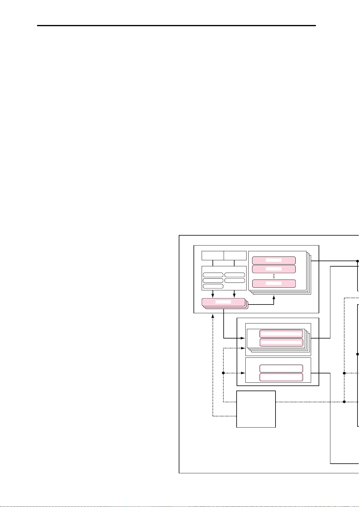
SAMPLING MODE
AUDIO INPUT
1
Insert Effect
IFX 1
IFX 2
IFX 3
Sample
Sample
Sample
AUDIO INPUT
2
IFX 4
IFX 5
Multisample
Multi Sample
Sample
Sample
Sample
GLOBAL MODE
DRUM KIT
Key
Drumsample / Sample - H
Assign
Drumsample / Sample - L
ARPEGGIATOR PATTERN
Preset Arpeggio Pattern:
User Arpeggio Pattern:
U000(I-A/B) – U327(E-H)
DISK MODE
P0 – 4
2
Page 9
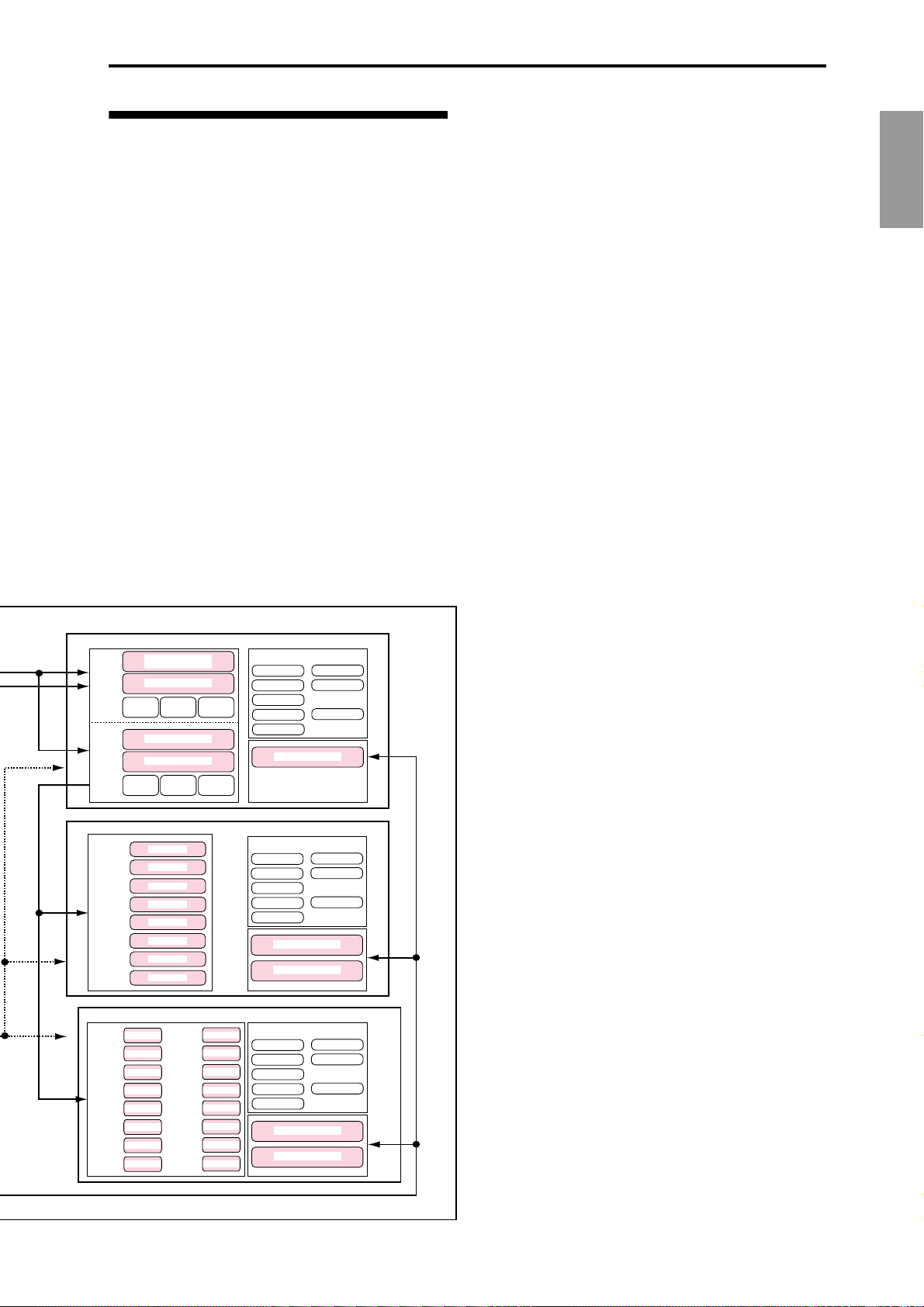
Overview of the modes
The TRITON-Rack has numerous functions: playing
and editing programs, combinations, or multis; recording and playing pattern data; recording samples; and
managing disk data. The largest unit used to organize
these functions is called a mode. The TRITON-Rack
has six modes.
Program mode
• Select and play programs
• Edit a program
Make settings for the oscillator , filter, amp, EG, LFO,
effects, and arpeggiator.
• The Audition function can be used.
Combination mode
• Select and play combinations
• Edit a combination
Make settings for volume, pan, layer/split etc. for
each timbre (program), and make settings for effects
and the two arpeggiators etc.
Multi mode
• The TRITON-Rack will function as a 16-track multitimbral tone generator.
PROGRAM
OSC 1
PITCH1
OSC 2
PITCH2
COMBINATION
TIMBRE 1
TIMBRE 2
TIMBRE 3
TIMBRE 4
TIMBRE 5
TIMBRE 6
TIMBRE 7
TIMBRE 8
MULTI
Program
TRACK 1
Program
TRACK 2
TRACK 3
Program
TRACK 4
Program
TRACK 5
Program
TRACK 6
Program
Program
TRACK 7
TRACK 8
Program
Multisample - H
Drum Kit
Multisample - L
FILTER1 AMP1
Multisample - H
Multisample - L
FILTER2
Program
Program
Program
Program
Program
Program
Program
Program
TRACK 9
TRACK 10
TRACK 11
TRACK 12
TRACK 13
TRACK 14
TRACK 15
TRACK 16
AMP2
Program
Program
Program
Program
Program
Program
Program
Program
Insert / Master Effect
IFX 1
IFX 2
IFX 3
IFX 4
IFX 5
Insert /Master Effect
IFX 1
IFX 2
IFX 3
IFX 4
IFX 5
Arpeggiator - A
Arpeggiatpr - B
Insert /Master Effect
IFX 1
IFX 2
IFX 3
IFX 4
IFX 5
Arpeggiator - A
Arpeggiatpr - B
MFX 1
MFX 2
Arpeggiator
MFX 1
MFX 2
MEQ
MFX 1
MFX 2
MEQ
MEQ
• For each of the 16 tracks, you can select a program,
and make level, pan, and effect settings.
• Up to 200 multis can be used, with 150 preset
patterns shared by all multis, and 100 user patterns
for each multi.
• Your playing can be recorded in a user pattern.
The performance generated by the arpeggiator can
also be recorded.
• You can play and make settings for the RPPR
(Realtime Pattern Play/Recording) function. Song
data included with the EXB-PCM03 etc. that uses
RPPR can also be played.
Sampling mode
• Sample sounds from an external audio device or
mic connected to the rear panel AUDIO INPUT
jacks. Insert effects can be applied to the external
input sound while you sample.
• Edit the waveform data you sampled or waveform
data that you loaded in Disk mode, and set loop
points etc.
• Edit multisamples consisting of two or more
samples.
• A multisample can be converted into a program, so
that a multisample created in Sampling mode can
be used in Program, Combination, or Multi modes.
Global mode
• Make settings that affect the entire TRITON-Rack,
such as master tune and global MIDI channel.
• Create drum kits (144 kits), arpeggio user patterns
(328 patterns), and user scales (16 one-octave scales
and 1 all-note scale).
• Create drum kits using the 413 internal
drumsamples (ROM). You can also use
drumsamples from an optional EXB-PCM series
board (if installed), or samples (RAM) that you
created in Sampling mode.
• Adjust the input level etc. from the AUDIO INPUT
1 and 2. These settings are valid in modes other
than Sampling mode. The TRITON-Rack’s effects
can be applied to the external input sound. (The
settings for Sampling mode are made
independently within Sampling mode.)
• Transmit data dumps of MIDI exclusive data.
Disk mode
• Data of each mode can be saved and loaded using
the floppy disk drive or an external SCSI device
(when the separately sold EXB-SCSI option is
installed).
• Media such as floppy disks or hard disks (when
the separately sold EXB-SCSI option is installed)
can be formatted, and data can be managed by
copying etc.
• Korg format sample data can be loaded and saved.
AKAI, AIFF, and WAVE format sample data can
be loaded. Sample data can be saved in Korg
format, or exported as AIFF or WAVE data.
• Songs that you created in Multi mode can be saved
in SMF format. SMF files can be loaded as Multi
mode patterns.
• You can use the Data Filer function (to save/load
MIDI exclusive data).
Introduction
3
Page 10
Front and rear panel
Front panel
1...10
11 17, 1822, 23
1. [INPUT] knob
This knob adjusts the input level of the AUDIO
INPUT 1 and 2 jacks.
2. [OUTPUT] knob
This knob adjusts the volume of the AUDIO OUTPUT (MAIN) L/MONO and R jacks, as well as the
headphone jack.
3. Headphone jack
A set of headphones (standard 1/4" stereo phone
plug) can be connected here (
The output from the AUDIO OUTPUT (MAIN) L/
MONO and R jacks can be monitored in stereo
through the headphones.
☞p.13).
4. Floppy disk drive
The TRITON-Rack includes a 3.5 inch disk drive,
capable of reading both 2DD (double-side doubledensity) and 2HD (double-side high density)
floppy disks. Edited data can be saved on a floppy
disk, and the factory preset data, SMF data, or
multisampling/sampling data etc. can be loaded
from a floppy disk.
For details on handling floppy disks, refer to “Cautions when handling floppy disks” (
Eject button
To remove a floppy disk, first make sure that the
disk access indicator is dark, and then press this
button. If the disk does not eject when you press
this button, do not attempt to remove the disk by
force. Please contact your dealer.
☞p.84).
12...16 24...2719...21
1
6
2
3
7 8
4
5. REALTIME CONTROLS [1], [2], [3], [4]
knobs
Use the [SELECT] key to select realtime controller
mode A/B/C, and use knobs [1]–[4] to control the
tone, effects, MIDI control changes, and arpeggiator etc. while you perform. (
A-mode
[1] LPF CUTOFF:
Controls the cutoff frequency of the low pass filter.
[2] RESONANCE/HPF:
Controls the filter resonance level or the high pass
filter cutoff frequency.
[3] EG-INTENSITY:
Controls the filter EG intensity.
[4] EG-RELEASE:
Controls the filter/amp release time.
5
910
☞p.19, p.21)
4
Disk access
indicator
Eject button
B-mode
Controls the functions that are assigned in each
mode (Program, Combination, Multi, or Sampling).
Page 11

C-mode
[1] TEMPO:
Controls the tempo of the arpeggiator or of the
Multi mode RPPR.
[2] ARP-GATE:
Controls the gate time (note duration) of the
arpeggiated notes. At the center position (12
o’clock), the setting of the arpeggiator “Gate”
parameter will be used. Rotating the knob toward
the left will shorten the time, and rotating it
toward the right will lengthen the time.
[3] ARP-VELOCITY:
Controls the velocity (playing strength) of the
arpeggiated notes. At the center position (12
o’clock), the setting of the arpeggiator “Velocity”
parameter will be used. Rotating the knob toward
the left will weaken the velocity, and rotating it
toward the right will strengthen the velocity.
[4] ———: not used
12. [F1 1/9], [F2 2/10], [F3 3/11], [F4 4/12],
[F5
5/13], [F6 6/14], [F7 7/15], [F8 8/16]
keys
Function [F1]–[F8] keys
These keys select the tabs that are displayed in
each page. They are also used to execute utilities
and other functions.
Timbre/track select [1/9]–[8/16] keys
By holding down the [TIMBRE/TRACK] key and
pressing a [1/9]–[8/16] key, you can select the
parameter of the corresponding timbre/track.
When the parameters of Combination timbres 1–8
or Multi mode tracks 1–8 or 9–16 are displayed in a
single page, these keys select one of these timbres/
tracks.
13. [TIMBRE/TRACK] key
☞(The above “Timbre/track select [1/9]–[8/16]
keys”)
Introduction
6. [A/B/C] LEDs
The currently selected REALTIME CONTROLS
mode will light. Use the [SELECT] key to select
modes A/B/C.
7. [SELECT] key
This key selects mode A, B, or C for the realtime
controllers. Each time you press the key, the [A/B/
C] indicators at the upper left will light alternately,
and A, B, or C mode will be selected.
The indicator of this key will blink at the currently
specified tempo.
8. [ARP ON/OFF] key
This key turns the arpeggiator on/off. When on,
the LED will light.
9. [AUDITION] key
This key plays a riff (phrase) appropriate for each
of the preloaded or preset program sounds. (Audi-
tion function)
In Program mode, pressing the [AUDITION] key
to make the indicator light will cause the audition
riff to play repeatedly. In Sampling mode, this key
is used to sound the selected sample.
10. [DEMO/SNG] key
This key accesses a page where you can listen to
demo songs.
11. LCD screen
Here you can select pages, and parameters, and set
values. (
☞p.9)
12 13
16 1415
14. [BANK] key
This key switches between internal (INT) and
external (EXB) banks.
15. [INT/EXB] LED
This indicates whether the currently selected program or combination is from an internal (INT) or
external (EXB) bank. The indicator will light if an
external bank (EXB) is selected. Use the [BANK]
key to switch between INT/EXB banks.
16. INT : [A], [B], [C], [D], [E-SMPL], [F-MOSS],
[G-GM] keys
EXB:[A], [B], [C], [D], [E], [F], [G], [H]
keys
In Program mode, these keys select the program
bank.
For the internal banks, pressing the [A], [B], [C],
[D], [E-SMPL], [F-MOSS], [G-GM] keys will select
INT-A (I-A), INT-B (I-B), INT-C (I-C), INT-D (I-D),
INT-E (I-E), INT-F (I-F)*, or G* banks.
* [F-MOSS] can be selected if the EXB-MOSS is
installed. Each time you press the [G-GM] key,
you will successively select G, g(1), g(2)–g(8),
g(9), g(d), G... and GM(2) variation banks and
drum banks.
For the external banks, pressing the [A], [B], [C],
[D], [E], [F], [G], or [H] keys will select the EXB-A
(E-A), EXB-B (E-B), EXB-C (E-C), EXB-D (E-D),
EXB-E (E-E), EXB-F (E-F), EXB-G (E-G), and EXBH (E-H) banks. Normally, the external banks are
used to load the included programs when the
EXB-PCM series options are installed.
In Combination mode, these keys select the combination bank.
For the internal banks, pressing the [A], [B], [C],
[D], and [E-SMPL] keys will select INT-A (I-A),
INT-B (I-B), INT-C (I-C), INT-D (I-D), or INT-E (IE) banks.
For the external banks, pressing the [A], [B], [C],
5
Page 12
[D], [E], [F], [G], or [H] keys will select the EXB-A
23 22
(E-A), EXB-B (E-B), EXB-C (E-C), EXB-D (E-D),
EXB-E (E-E), EXB-F (E-F), EXB-G (E-G), and EXBH (E-H) banks. Normally, the external banks are
used to load the included combinations when the
EXB-PCM series options are installed.
When the program of a Combination mode or
Multi mode timbre/track is selected, these keys
are used to select the program bank.
In dialog boxes such as Write Program or Write
Combination, these keys are used to specify the
program or combination bank that will be the
writing destination, etc.
19. CURSOR keys [ –], [ ], [ ], [ +]
Use these keys to select different parameters on
screen.
By holding down the [MENU] key and using cursor keys [ ], [ ] you can switch pages in the
order of 1.1→2.1→2.2→2.3. (
☞p.10)
20. [EXIT] key
In Program, Combination, Multi, Sampling, and
Global modes, pressing this key from anywhere
other than page 1.1 will take you to page 1.1 of that
mode.
When a dialog box is open, this key will cancel the
settings made in the dialog box and close the dialog box (corresponds to the “Cancel”). If a Utility
menu or page menu is open, pressing [EXIT] will
close the menu.
17 18
17. Mode keys
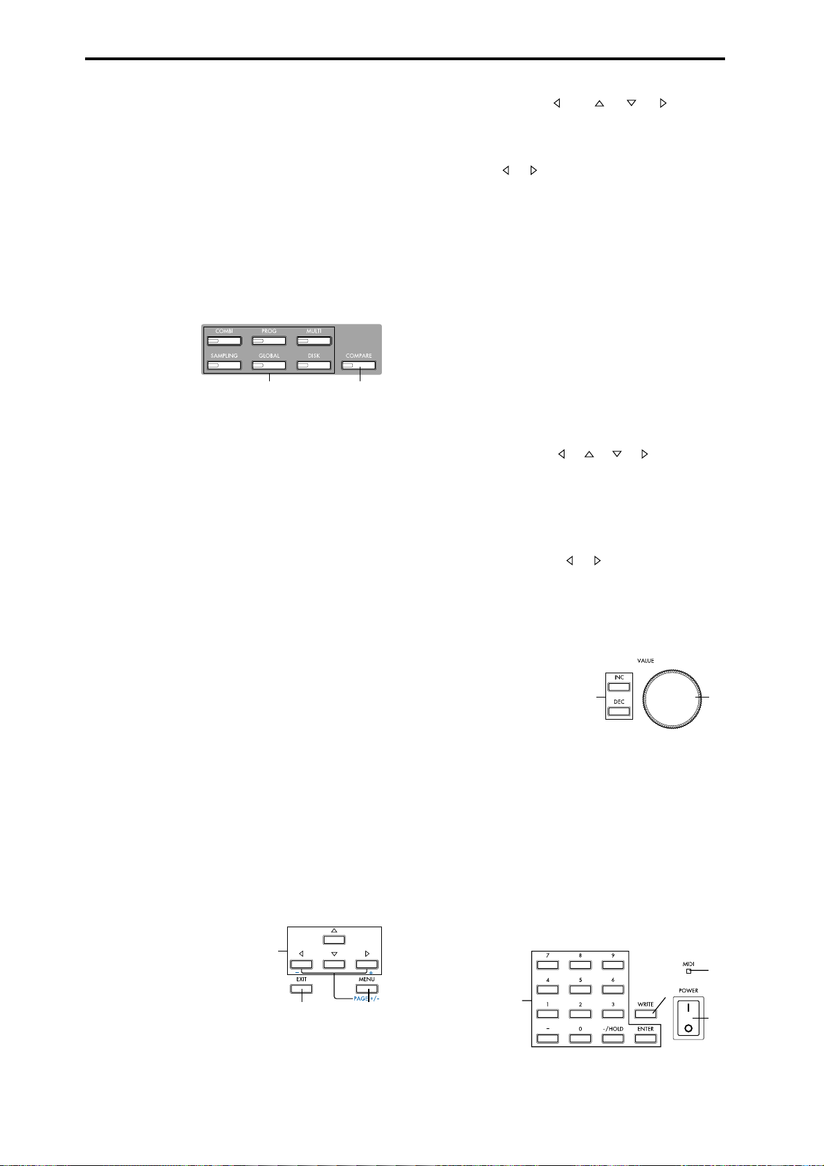
Use these keys to enter the desired mode.
When you press a key, the LED will light, and you
will enter the mode whose key you pressed (
p.34).
[COMBI] key
Combination mode will be selected.
[PROG] key
Program mode will be selected.
[MULTI] key
Multi mode will be selected.
[SAMPLING] key
Sampling mode will be selected
[GLOBAL] key
Global mode will be selected
[DISK] key
Disk mode will be selected.
18. [COMPARE] key
Use this key to compare the edited sound of a program or combination with the sound that was
written into memory before editing. This key is
also used in Multi mode when recording a pattern
and to make before- and after-editing comparisons. (
☞p.35)
☞p.3,
21. [MENU PAGE +/–] key
Use this key to select different pages on screen.
When you press this key, a list of the pages within
the mode will appear in the LCD screen. Use [F1]–
[F7] or cursor keys [ ], [ ], [ ], [ ] to select the
desired page, and press the [F8] key to move to the
selected page.
You can also move to a desired page by holding
down the [MENU] key and using numeric keys
[0]–[9] to enter a two-digit page number.
In addition, you can hold down the [MENU] key
and use cursor keys [ ], [ ] to switch pages in
the order of 1.1→2.1→2.2→2.3. (
☞p.34)
VALUE controllers
The following VALUE controllers are used to set
the value of a selected parameter (
☞p.35).
22. [VALUE] dial
Use this to increase or decrease the value of a
parameter. It is convenient to use the dial when
you wish to change the value of a parameter by a
large amount.
23. [INC], [DEC] keys
Use these keys to increment or decrement a
parameter value in steps of one. It is convenient to
use these keys when you wish to change the value
of a parameter in small steps.
6
19
20
21
24
26
25
27
Page 13
24. Numeric keys [0], [1], [2], [3], [4], [5],
[6], [7], [8], [9]
[–] key
[./HOLD] key
[ENTER] key
Use these keys to numerically input a parameter
value. Use numeric keys [0]–[9], the [–] key, and
the [./HOLD] key to enter the value, and press the
[ENTER] key to confirm it. The [–] key inverts the
sign (+/–) of the parameter value. The [./HOLD]
key lets you input a value with a decimal point.
The [./HOLD] key is also used when you wish to
hold the 10’s place while selecting programs or
combinations. (
By holding down the [ENTER] key and pressing a
numeric key [0]–[9], you can select up to ten Utility menu commands in the current page.
☞PG p.2)
25. [WRITE] key
In Program, Combination, and Global modes, this
key is used to write data into memory. Pressing the
[WRITE] key in these modes will open a dialog
box. Then press the [F8] (“OK”) key to write the
edited content. (
☞p.37, p.39)
26. [MIDI] LED
This will light when the TRITON-Rack receives
MIDI messages.
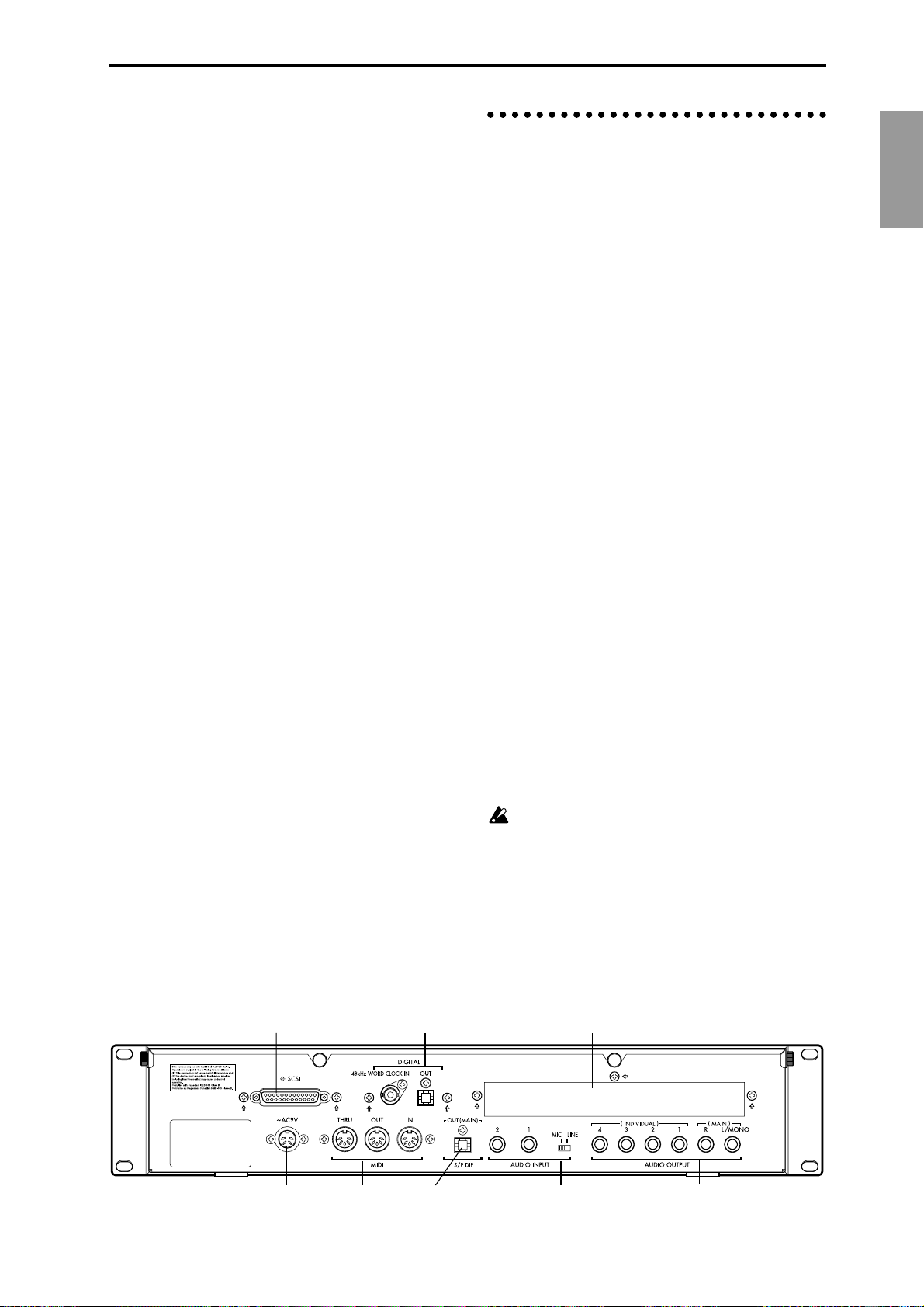
Rear panel
1. AC power supply connector (~AC9V)
Connect this to the included AC/AC power supply.
After connecting the power supply cable to the
TRITON-Rack, connect the other end to an AC
outlet (
☞p.12).
2. MIDI
THRU connector
MIDI data and sound settings etc. that are received
at the MIDI IN connector are re-transmitted without change from the MIDI THRU connector.
You can use this to connect multiple MIDI devices
via MIDI cables.
OUT connector
MIDI data and sound settings etc. are transmitted
from this connector.
Use this to control another connected MIDI device
from the TRITON-Rack.
IN connector
MIDI data and sound settings etc. are received at
this connector.
Use this to play the TRITON-Rack from another
connected MIDI device (
☞p.13).
Introduction
27. [POWER] switch
This switch turns the power on/off (☞p.15).
6 7
3. S/P DIF OUT(MAIN) jack
This is an optical type S/P DIF format (IEC60958,
EIAJ CP-1201) digital output jack (stereo).
It digitally outputs the same audio signal as the
AUDIO OUTPUT (MAIN) L/MONO and R jacks,
at sampling rate of 48 kHz.
Use an optical cable to connect this to the optical
digital input jack of a DAT or MD, etc.
The [OUTPUT] knob does not adjust the output
level of this jack.
4. AUDIO INPUT
These two audio inputs are used when recording a
mono/stereo sample from a mic or external audio
source (
Rack’s internal effects to an external audio source
(
☞p.29), or when applying the TRITON-
☞p.97).
8
1523
4
7
Page 14

The MIC/LINE level select switch ([MIC/LINE]
switch) and the level adjustment knob ([INPUT]
knob) allow you to use a wide range of external
audio sources, from mic level to line level.
AUDIO INPUT 1/2 jacks
These are unbalanced 1/4" phone jacks. (☞p.107).
[MIC/LINE] switch
This switches the input level of the AUDIO INPUT
1/2 jacks (
☞p.107).
5. AUDIO OUTPUT
Connect these outputs to the input jacks of your
amp or mixer. In addition to the L/MONO and R
main stereo audio outputs, the TRITON-Rack provides four individual audio outputs. The sound
from each oscillator, drum, timbre/track, or insertion effect can be freely routed to any output
(
☞p.95–).
By connecting this to the DIGITAL IN jack of an
ADAT Optical format compatible mixer, amp, or
recorder etc., you can send the audio signal output
of the TRITON-Rack in digital form to an external
mixer, amp, or recorder etc. Use an optical cable
made by the Alesis Corporation or an optical cable
for CD/DAT (both sold separately) to make this
connection (
The [OUTPUT] knob does not adjust the output
level of this connector.
☞p.14, PG p.243, p.273).
48 kHz WORD CLOCK IN jack
Connect this to the WORD CLOCK OUT jack of an
ADAT Optical format compatible mixer or remote
controller. Use this when you want the connected
device to be the word clock master and the TRITON-Rack to be the word clock slave for synchronization. Use an BNC coax cable made by the
Alesis Corporation or a video BNC cable (both
sold separately) to make this connection.
(MAIN) L/MONO, R jacks
These are unbalanced phone jacks (☞p.106).
These are the main audio output jacks. By setting
“Bus Select” to L/R, the output from an oscillator,
an insertion effect, an individual drum part, or the
metronome can be output to the (MAIN) L/
MONO and R jacks.
When making connections in stereo, use L/
MONO and R. When making connections in
mono, use the L/MONO jack.
(INDIVIDUAL) 1, 2, 3, 4 jacks
These are unbalanced phone jacks (☞p.106).
These are individual (independent) audio output
jacks. By several times to make the “Bus Select” to
1, 2, 3, 4, 1/2, or 3/4, an oscillator, an insertion
effect, an individual drum part, or the metronome
etc. can be assigned to be output from the (INDIVIDUAL) 1, 2, 3, 4, jacks. The output from the 1, 2,
3, 4 jacks is not affected by the [OUTPUT] knob.
6. SCSI connector (separately sold EXB-SCSI
option)
Use a SCSI cable to connect SCSI-compatible
devices (hard disk drives, CD-ROM drives etc.)
here (
☞p.14, PG p.243).
8. mLAN (separately sold EXB-mLAN
option)
A special cable is used to connect mLAN-compatible devices or computers. (
☞p.14, PG p.243)
mLAN (IEEE 1394) 1, 2, 3 jacks
SERIAL I/O connector
For details refer to the manual included with the
EXB-mLAN.
What is mLAN?
mLAN is a new standard for musical instruments that uses
the general-purpose IEEE 1394 interface (a general-purpose
interface with a wide range of uses including current and digital AV devices) with a special transmission protocol for musical data. It allows high quality digital audio and MIDI data to
be simultaneously transmitted and received over a single
cable. At a transmission speed of 200 Mbps, approximately
100 channels of audio data or 256 ports of MIDI data (i.e., 16
channels x 256 connectors) can be transmitted and received
over a single cable.
mLAN provides unprecedented flexibility, allowing you to
daisy-chain up to 63 devices, and even to reconfigure the
input and output connections between devices without actually disconnecting the mLAN cable. Even sophisticated setups in the studio or on stage are made easy by mLAN.
7. DIGITAL (separately sold EXB-DI option)
OUT jack
This is an ADAT optical format digital output connector.
It outputs the six channels of the TRITON-Rack’s
AUDIO OUTPUT jacks (MAIN) L/MONO, R,
(INDIVIDUAL) 1, 2, 3, 4 (analog audio outputs) as
digital audio with a sampling rate of 48 kHz.
These signals are output as channels 1 through 6 of
the ADAT optical format.
8
Page 15
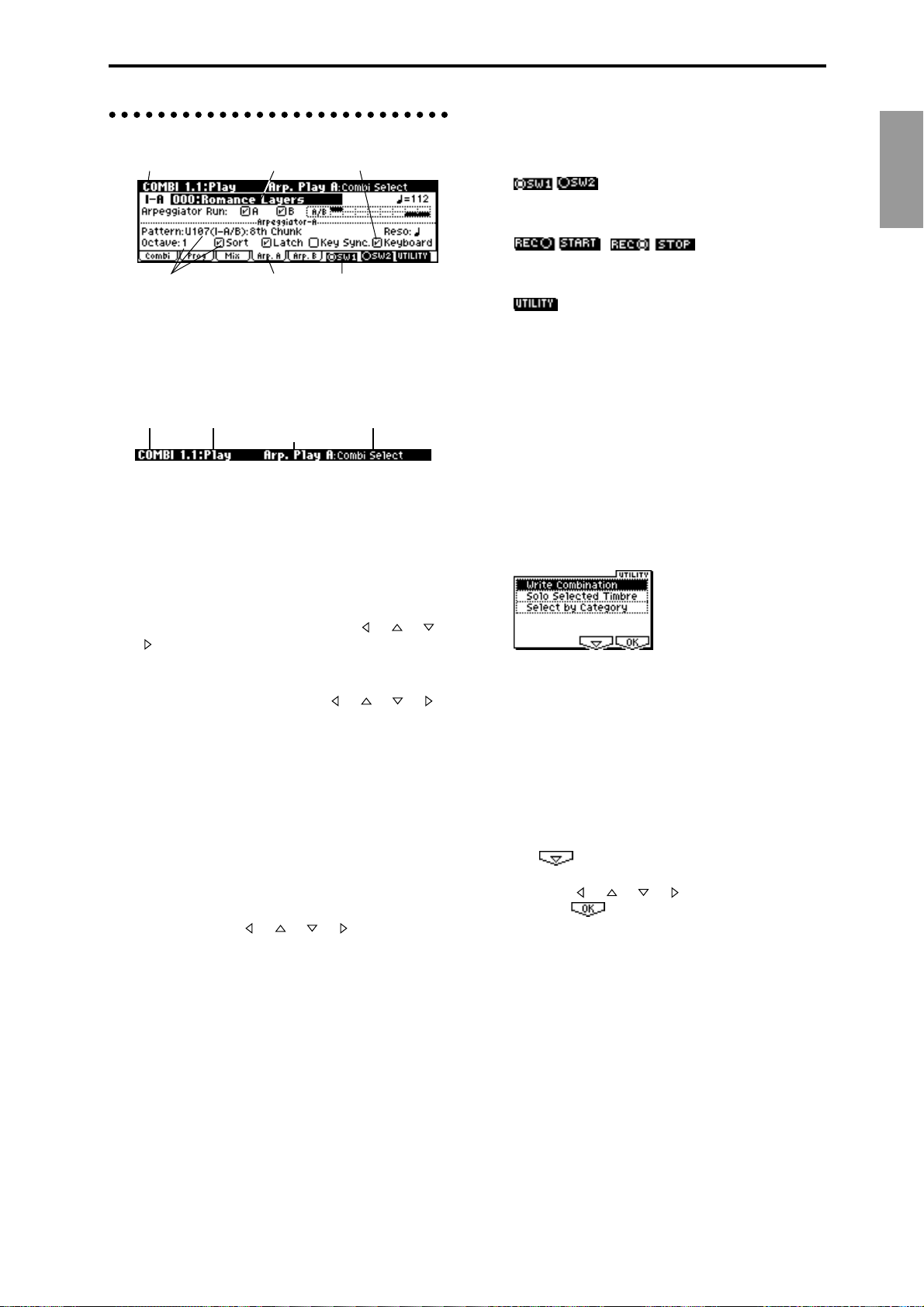
Objects and functions in the LCD screen
a: Current page d: Edit cell e: Check box
c: Parameter f: Function button
a: Current page
This indicates the currently selected page within
the mode. From the left, this area shows the mode
name, page number:name, tab name, and the
parameter name of the edit cell.
Mode name
Page number: name Parameter name
b: Tab
Most pages are divided into two or more tabs. By
pressing the closest function key [F1]–[F7], you can
select a tab to access the corresponding page.
b: T ab
Tab name
f: Function buttons
By pressing the function key [F1]–[F8] nearest this
button, you can turn various functions on/off.
:
SW1 and SW2 in Program, Combination, Multi, or
Sampling modes.
, :
Starts/stops pattern recording in Multi mode,
starts/stops sample recording in Sampling mode.
:
Accesses the utility menu where you can execute
utility menu commands.
Other function buttons examples
Multi mode: REVERT (copy and paste RPPR
settings)
Sampling mode: INSERT, CUT, COPY, CREATE
(create multisample), L/R,
ZOOM
Global mode: TEXT, KEY+, –
Disk mode: UP, OPEN
Demo: START, STOP
* Utility menu
Introduction
c: Parameters
The parameters for various settings are displayed
in the LCD screen. Use cursor keys [ ], [ ], [ ],
[ ] to select the desired parameter.
d: Edit cell
When you use the cursor keys [ ], [ ], [ ], [ ],
the selected parameter will be highlighted in the
LCD screen. This area is called the edit cell, and
your editing will affect the highlighted area.
The parameter value of the edit cell can be modified using VALUE controllers such as the [VALUE]
dial or the [INC], [DEC] keys (
ters that require you to enter a key or a velocity
value, you can input the value by holding down
the [ENTER] key and playing a note on a connected MIDI instrument.
☞p.35). For parame-
e: Check box
Use cursor keys [ ], [ ], [ ], [ ] to select a
check box (edit cell), and use a VALUE controller
such as the [VALUE] dial or the [INC], [DEC] keys
to add or remove the check mark.
When checked, the parameter will function, when
unchecked, the parameter will not function.
In each page, you can press the “UTILITY” function button (the [F8] key) to access the utility
menu. The utility menu contains commands that
can be used in that page. The utility menu that
appears will differ depending on the page that is
selected.
You can also select up to ten utility menu commands by holding down the [ENTER] key and
pressing a numeric key [0]–[9]. Press the [EXIT]
key to close the utility menu.
For , press the [F7] key to select the desired
utility menu command. You can also use the cursor keys [ ], [ ], [ ], [ ] to make your selection. For , press the [F8] key to open the
dialog box of the selected utility menu command.
This key also switches the status of commands that
you check or uncheck.
9
Page 16
* Dialog boxes
When you select a utility menu command etc., a
dialog box will open.
Use the cursor keys [ ], [ ], [ ], [ ] to select
parameters. Use the VALUE controllers (
input the parameter values. When selecting program or combination numbers in a dialog box, you
can use the [BANK] and [A]–[H] keys in addition
to the VALUE controllers.
As in the utility menu, press the function key [F1]–
[F8] nearest etc. (function button 2) to access
the execution or operation screen. In some cases, a
dialog box will appear. Follow the directions
shown in the dialog box.
To execute, select (press the [F8] key). To
cancel without executing, select (press the
[F7] key). The dialog box will close. The [EXIT] key
is equivalent to “Cancel,” “Done,” or “Exit.”
* Function buttons 2
Press the function key [F1]–[F8] nearest this button
to execute the function.
:
Utility menu, etc.
* Text dialog box
When you use the function keys to select , a
text dialog box will appear.
In this dialog box you can rename text (e.g., the
name of a program, combination, or multi).
(
☞p.38)
☞p.35) to
* Page menu
In Combination, Program, Multi, Sampling, or
Global modes, pressing the [MENU] key will display a list of the pages in that mode. (The page in
which you where when you pressed the [MENU]
key will be highlighted.)
To select a page, press the nearest function key
[F1]–[F7]. By pressing the same key you can move
consecutively downward. You can also use cursor
keys [ ], [ ], [ ], [ ] to move left/up/down/
right.
You can also move to the desired page by holding
down the [MENU] key and using numeric keys
[0]–[9] to enter a two-digit page number. In addition, you can hold down the [MENU] key and use
the cursor keys [ ] [ ] to move in steps of one
page; in the example shown below, this would be
Play → P/M → Ctrl → MOSS (if the EXB-MOSS is
installed) → Prm1 → ... etc.
* Other objects
To use slider- or knob-shaped objects, or chain
parameter values, use the cursor keys [ ], [ ],
[ ], [ ] to select the desired item, and use the
VALUE controllers to adjust the value.
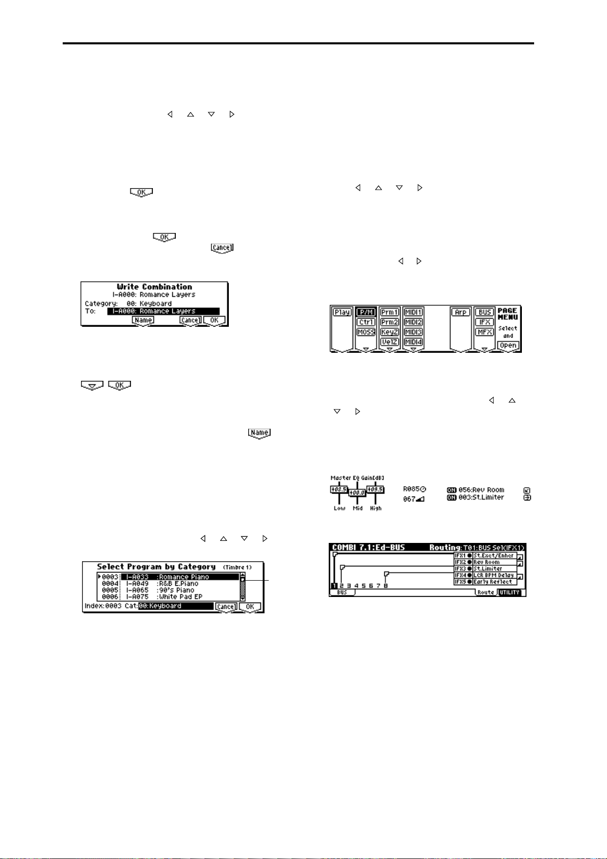
Other types of objects are shown in the effect routing screen. (
☞p.96)
Knobs ChainSliders
* Scroll bar
This indicates that the list contains selections or
parameters that cannot all be shown in the screen
at once. Use the cursor keys [ ], [ ], [ ], [ ] to
move within the list.
Scroll
bar
Routing
10
Page 17

Setup
11
Page 18
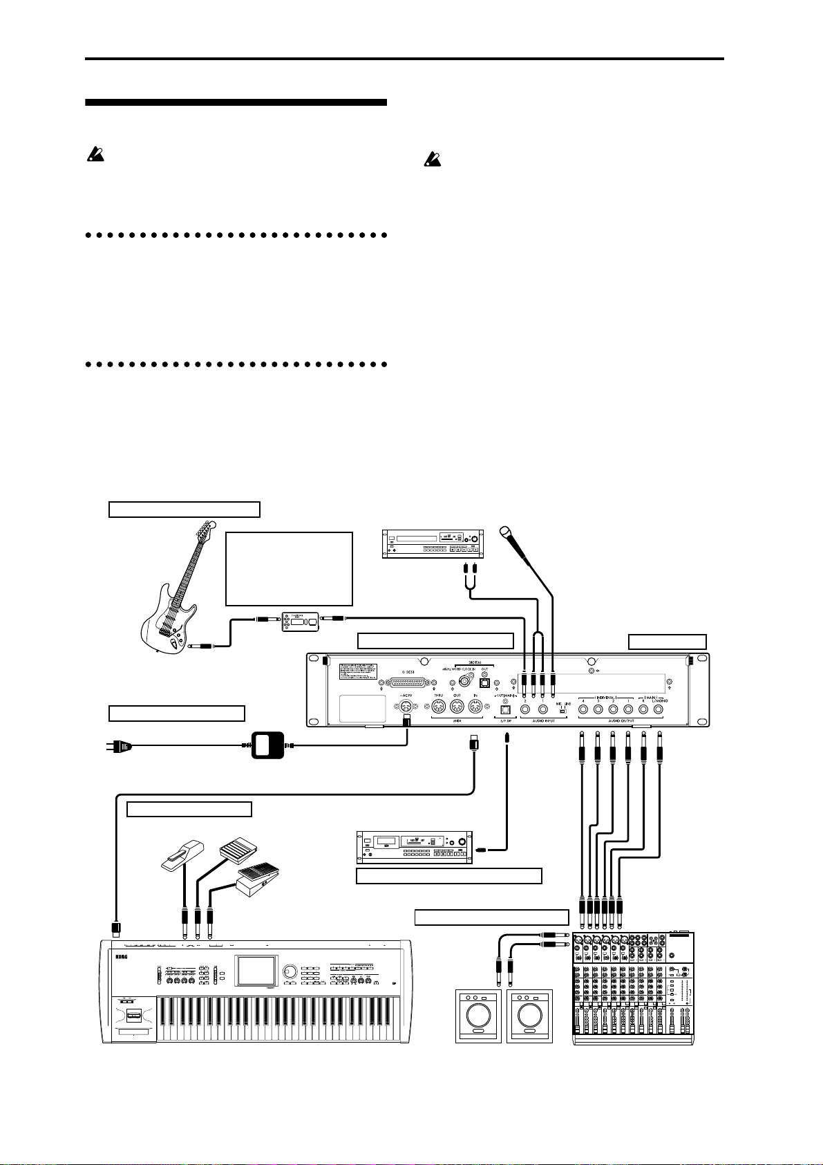
Connecting audio equipment etc.
Connections must be made with the power turned
off. Please be aware that careless operation may
damage your speaker system or cause malfunctions.
1. Connecting the power cable
● Connect the included AC/AC power supply to the
AC power supply inlet of the TRITON-Rack, and
then connect the other end of the cable to an AC
outlet.
2. Connecting audio output devices
AUDIO OUTPUT (MAIN) L/MONO, R
(INDIVIDUAL) 1, 2, 3, 4
Here, you can connect a set of amplified monitor
speakers or your audio system to output the TRITONRack’s sound.
If you wish to use the AUDIO OUTPUT (INDIVIDUAL) 1–4 jacks of the TRITON-Rack, we recommend
that you use a mixer.
If you playback the TRITON-Rack through your
stereo audio system, be aware that high volumes
may damage your speakers. Be careful not to raise
the volume excessively.
● Connect the AUDIO OUTPUT (MAIN) L/MONO
and R jacks to the INPUT jacks of your powered
monitor system, mixer etc.
L/MONO and R are the main outputs. If you are
outputting in stereo, make connections to the
(MAIN) L/MONO jack and the R jack. If you are
outputting in monaural, make connections to the
(MAIN) L/MONO jack. We recommend that you
playback in stereo if possible.
● If you wish to output from the AUDIO OUTPUT
(INDIVIDUAL) 1, 2, 3, 4 jacks, connect these jacks
to your mixer, and then connect the mixer output
to the INPUT of your powered monitor system etc.
For details on the output of each jack (
☞p.95–“Rout-
ing”).
3. Connecting audio input devices
If a passive type guitar (a guitar
without an internal preamp) is
Guitar
connected, it will not be possible to
sample at an appropriate level due
to the impedance mismatch. Such
instruments must be connected via
a preamp or effect unit.
1. Connecting the power cable
to an AC outlet
MIDI cable
Connecting MIDI equipment
DP-1H etc.
MIDI OUT
Effect processor etc.
TRITON-Rack
PS-1 etc.
XVP-10, EXP-2 etc.
MIDI keyboard
AC/AC power supply
Mic
CD player, analog record
player, etc.
AUDIO INPUT
Connecting separately sold options
~ AC9V
MIDI IN
DAT, MD etc.
S/P DIF
DIGITAL IN
4. Connecting digital recording equipment
2. Connecting audio output devices
Powered monitors,
etc.
INPUT
Monitor
OUTPUT
Rack installation
AUDIO
OUTPUT
Mixer
INPUT
MAIN OUTS
TAPE
TAPE
STEREO AUX RETURNS
AUX SEND
MIC4
MIC6
MIC3
MIC5
MIC2
MIC1
BAL
BAL
BAL
BAL
OR
OR
OR
OR
UNBAL
UNBAL
UNBAL
UNBAL
LINE IN 4
LINE IN 3
LINE IN 5
LINE IN 2
LINE IN 1
LOW CUT
LOW CUT
LOW CUT
LOW CUT
75Hz
75Hz
75Hz
75Hz
18dB/OCT
18dB/OCT
18dB/OCT
18dB/OCT
B
d
V
0
B
d
B
B
V
d
d
V
1
V
0
0
0
-
1
1
1
-
-
-
G
A
G
A
G
I
G
C
A
A
N
I
I
C
I
I
C
C
N
N
I
N
I
I
M
M
M
M
U
U
U
U
U
10
60
10
10
60
10
60
60
+10dB
-40dB
+10dB
-40dB
+10dB
+10dB
-40dB
-40dB
TRIM
TRIM
TRIM
TRIM
U
U
U
U
AUX
AUX
AUX
AUX
1
1
1
1
MON/
MON/
MON/
MON/
EFX
EFX
EFX
EFX
+15
+15
+15
+15
U
U
U
U
2
2
2
2
EFX
EFX
EFX
EFX
+15
+15
+15
+15
U
U
U
U
EQ
EQ
EQ
EQ
HI
HI
HI
HI
12kHz
12kHz
12kHz
12kHz
-15
+15
-15
-15
-15
+15
+15
-15
+15
U
U
U
U
MID
MID
MID
MID
2.5kHz
2.5kHz
2.5kHz
2.5kHz
-12
-12
+12
-12
-12
-12
+12
+12
+12
U
U
U
U
LOW
LOW
LOW
LOW
80Hz
80Hz
80Hz
80Hz
+15
-15
-15
+15
+15
+15
-15
-15
-15
PAN
PAN
PAN
PAN
L
R
L
L
L
R
R
R
4
1
3
2
MUTE
MUTE
MUTE
MUTE
ALT 3–4
ALT 3–4
ALT 3–4
ALT 3–4
dB
dB
dB
dB
dB
10
10
10
10
10
SOLO
SOLO
SOLO
SOLO
5
5
5
5
5
U
U
U
U
U
5
5
5
5
5
10
10
10
10
10
20
20
20
20
20
30
30
30
30
30
40
40
40
40
40
50
50
50
50
50
60
60
60
60
60
OUTPUT
L
INPUT
1
1
L
2
R
2
R
BAL/UNBAL
ALL BAL/UNBAL
LEFT(1/MONO)
RIGHT
BAL
BAL
MONO
MONO
MONO
MONO
OR
OR
UNBAL
UNBAL
L
L
L
L
LINE IN 6
BAL
BAL
BAL
BAL
OR
OR
LOW CUT
OR
OR
LOW CUT
75Hz
75Hz
UNBAL
UNBAL
UNBAL
UNBAL
18dB/OCT
18dB/OCT
B
B
d
d
V
V
0
0
1
1
-
-
R
R
R
R
G
A
G
A
I
C
I
C
N
N
I
I
M
M
U
LEVEL
LEVEL
LEVEL
LEVEL
+4
+4
+4
+4
10
10
60
60
+10dB
+10dB
-40dB
-40dB
TRIM
TRIM
U
U
AUX
AUX
1
1
MON/
MON/
EFX
EFX
+15
+15
U
U
2
2
EFX
EFX
+15
+15
U
U
EQ
EQ
HI
HI
12kHz
12kHz
-15
+15
+15
U
U
MID
MID
2.5kHz
2.5kHz
-12
+12
+12
U
U
LOW
LOW
80Hz
80Hz
+15
-15
+15
PAN
PAN
L
R
L
R
6
5
MUTE
MUTE
ALT 3–4
ALT 3–4
dB
10
SOLO
SOLO
5
U
5
10
20
30
40
50
60
PHONES
-10
-10
-10
-10
LINE IN 7-8
LINE IN 13-14
LINE IN 9-10
LINE IN 11-12
U
U
U
U
U
U
AUX
AUX
AUX
AUX
1
1
1
1
MON/
MON/
MON/
MON/
EFX
EFX
EFX
EFX
+15
+15
U
U
2
2
EFX
EFX
+15
+15
U
U
EQ
EQ
HI
HI
12kHz
12kHz
-15
+15
-15
+15
U
U
MID
MID
2.5kHz
2.5kHz
-12
+12
-12
+12
U
U
LOW
LOW
80Hz
80Hz
+15
-15
+15
-15
PAN
PAN
L
R
L
R
9–10
7–8
MUTE
MUTE
ALT 3–4
ALT 3–4
dB
dB
dB
10
10
10
SOLO
SOLO
5
5
5
U
U
U
5
5
5
10
10
10
20
20
20
30
30
30
40
40
40
50
50
60
60
1
+20
+10
+15
+15
NORMALLED
U
U
U
AUX 1 MASTER
2
PRE
2
2
POST
EFX
EFX
AUX
EFX TO
AUX 1
+20
MONITOR
+15
SELECT
+15
RETURNS
U
U
SOURCE
EQ
EQ
LEFT RIGHT
HI
HI
MAIN
CLIP+28
12kHz
12kHz
MIX
+10
-15
+15
-15
+15
+7
U
U
ALT
+4
3-4
MID
MID
2.5kHz
2.5kHz
+2
-12
-12
+12
+12
0
TAPE
U
U
-2
LOW
LOW
80Hz
80Hz
-4
+15
+15
-15
-15
-7
ASSIGN
PAN
PAN
-10
TO MAIN MIX
-20
NORMAL(AFL)
-30
LEVEL SET(PFL)
L
L
R
R
0dB=0dBu
SOLO
MODE
13–14
11–12
MUTE
MUTE
POWER
RUDE SOLO LIGHT
PHANTOM
ALT 3–4
ALT 3–4
CONTROL
/ PHONES
MAIN MIX
ROOM
dB
dB
dB
10
10
10
SOLO
SOLO
5
5
5
U
U
U
5
5
5
10
10
10
20
20
20
30
30
30
40
40
40
50
50
50
50
60
60
60
60
12
Page 19
Headphones
● When using headphones, plug them into the head-
phones jack located on the front panel.
Headphone
Connecting MIDI equipment
The TRITON-Rack produces sound when it receives
MIDI messages from another MIDI device such as a
MIDI keyboard or sequencer (computer).
Use a MIDI cable to make these connections.
Connecting a MIDI keyboard
3. Connecting audio input devices
Here, you can connect or the OUTPUT jacks of external
audio devices to the AUDIO INPUT 1, 2 jacks.
● In Sampling mode these jacks sample the sound
input from an external source.
For details on settings in Sampling mode, refer to
p.29, p.68.
● In Program, Combination, and Multi modes, the
sound input from an external source can be monitored, processed by effects, and output to the OUTPUT jacks.
For details on the settings in these modes for routing sound to the OUTPUT jacks, refer to p.97.
4. Connecting digital recording equipment
● Connect the S/P DIF OUT (MAIN) jack of the TRI-
TON-Rack to a DAT or MD that has an S/P DIF IN
jack.
The S/P DIF OUT (MAIN) jack outputs the same
audio signal as the AUDIO OUTPUT (MAIN) L/
MONO and R jacks, at a sampling frequency of
48 kHz.
Controlling the tone generator of the TRITON-Rack
from a MIDI keyboard
● MIDI OUT connector of the MIDI keyboard →
MIDI IN connector of the TRITON-Rack
MIDI OUT TRITON
TRITON-RackMIDI IN
● MIDI OUT connector of the MIDI keyboard →
MIDI IN connector of the TRITON-Rack (1) →
MIDI THRU connector of the TRITON-Rack (1) →
MIDI IN connector of the TRITON-Rack (2)
MIDI OUT TRITON
MIDI IN
MIDI THRU
MIDI IN
TRITON-Rack (2)
TRITON-Rack (1)
MIDI channel settings
MIDI messages are conveyed when the transmitting
and receiving devices are set to matching MIDI channels. There are sixteen MIDI channels, 1–16. Channels
are handled differently, depending on the mode.
● Initially, select MIDI channel 1 on the MIDI
instrument that is connected to the TRITON-Rack
to control it.
With the factory settings, the global MIDI channel
(GLOBAL 2.1: MIDI “MIDI Channel”) is set to 1. In
Program mode and Sampling mode, MIDI messages
are transmitted and received on the global MIDI channel. With the factory settings, the various combinations
in Combination mode are also set to be operated on
the global MIDI channel. Multi mode is usually used
to receive channel messages transmitted from a
sequencer (computer) so that multiple channels can be
controlled independently. (
☞PG p.221)
Setup
13
Page 20
Connecting a sequencer (computer)
Basic settings for using the TRITON-Rack as the
MIDI tone generator for monitoring and playback
when recording on an external sequencer or computer
● MIDI OUT connector of the MIDI keyboard →
computer with MIDI interface → TRITON-Rack
For details on connecting the computer and MIDI
interface, and making MIDI port settings, refer to
the owner’s manual for your MIDI interface.
Computer
MIDI
interface
MIDI IN
MIDI OUT
* Echo Back is a function by which data received at
MIDI IN is re-transmitted without change from
MIDI OUT.
Computer
MIDI interface
(multi-port)
MIDI IN
MIDI OUTMIDI IN
MIDI OUT
MIDI INMIDI OUT
MIDI keyboard etc.
TRITON-Rack
Rack installation
MIDI OUT
MIDI IN
MIDI keyboard etc.
TRITON-Rack
When recording the MIDI output of the TRITONRack’s controllers, arpeggiator, and RPPR into the
external sequencer or computer
● MIDI OUT connector of the TRITON → MIDI IN
connector of the TRITON-Rack, MIDI OUT connector of the TRITON-Rack → MIDI IN connector
of the MIDI interface
Computer
MIDI
interface
MIDI IN
MIDI OUT
MIDI INMIDI OUT
MIDI keyboard etc.
TRITON-Rack
When recording the MIDI output of the TRITONRack’s controllers, arpeggiator, and RPPR into the
external sequencer or computer, and using the TRITON-Rack as the monitor and playback MIDI tone
generator during recording
● MIDI OUT connector of the MIDI keyboard →
MIDI IN connector of the MIDI interface (multiport), MIDI OUT connector of the MIDI interface
(multi-port) → MIDI IN connector of the TRITONRack, MIDI OUT connector of the TRITON-Rack
→ MIDI IN connector of the MIDI interface
(multi-port)
Make the appropriate settings for the Local Control
parameter of the TRITON-Rack and for the Echo
Back* parameter of the external sequencer (computer), so that the TRITON-Rack’s controllers,
arpeggiator, and RPPR are not applied to the tone
generator in duplicate. (
☞PG p.228)
If you intend to mount the TRITON-Rack in a rack,
insert insulating washers and insulating bushings into
the holes of the TRITON-Rack’s faceplate, as shown
below.
If you place the TRITON-Rack directly on a table
for use, please do not place other racks or a computer etc. on top of it.
Front panel
TRITON-Rack
Bolt
Insulating washer
EIA standard case
Insulating bushing
About separately sold options
The TRITON-Rack can be upgraded withg user installable options, which add feartures.
If the separately sold EXB-SCSI option is installed, you
can connect SCSI devices such as hard disks or CDROM drives.
If the separately sold EXB-DI option is installed, you
can connect ADAT Optical format compatible mixers,
amps, or recorders.
By installing the optional EXB-mLAN, you can connect
the TRITON-Rack to the new digital network designed
specifically for musical applications --- mLAN. This
allows a single IEEE 1394 cable to handle MIDI input/
output signals and all audio output signals of the TRITON-Rack (which would otherwise require eight
cables), for easy connection to another mLAN-compatible device or computer. mLAN makes it easy to construct sophisticated systems that exchange large
volumes of high-quality digital audio data and MIDI
data.
For details on installing the EXB-SCSI, EXB-DI, or
EXB-mLAN refer to PG p.243.
A CD-ROM drive can be connected to only load.
Y ou cannot save to a CD-ROM drive fr om the SCSI
port.
14
Page 21
Turning the power on/off
Before you turn on the power, make sure that the
desired connections have been made as described
in “Setup” (
1. Turning the power on
1 Press the TRITON-Rack’ s [POWER] switch to turn
on the power.
The LCD screen will show the model name and software version of your TRITON-Rack.
(The following graphic shows the factory-set LCD
screen of the TRITON-Rack. The version number is
subject to change without notice.)
2 Turn on your powered monitors or stereo amp.
3 Raise the TRITON-Rack’s [OUTPUT] knob to an
appropriate level, and adjust the volume of your
powered monitors or stereo amp.
2. Turning the power off
1 Set the TRITON-Rack’s [OUTPUT] knob and the
volume of your powered monitor or stereo amp to
zero.
2 Turn off the power of your powered monitor or
stereo amp.
3 Press the TRITON-Rack’ s [POWER] switch to turn
off the power.
Never turn off the power while data is being written into internal memory.
If the power is turned off while processing is being
performed, memory write operations will not be
completed correctly. If this occurs, the TRITONRack will automatically initialize its internal memory so that it will operate correctly. This is not a
malfunction.
Data is written into internal memory by the following operations.
While data is being written, the LCD screen will
indicate “Now writing into internal memory.”
• Writing (updating) a Program, Combination,
Global Setting, Drum Kit, or Arpeggio Pattern
• Loading Program, Combination, Global
Setting, Drum Kit, or Arpeggio Pattern data in
Disk mode
• Receiving a MIDI data dump for Program,
Combination, Global Setting, Drum Kit, or
Arpeggio Pattern data
☞p.12–p.14).
• When using a Sampling mode utility menu
command (“Move Sample,” “Move MS,” “Conv.
To Prog,” “Time Slice” etc.) to simultaneously
modify programs or drum kits.
The mode and page that will be selected when the
power is turned on
The state of the TRITON-Rack when the power is
turned on will depend on the setting of “Power On
Mode” (GLOBAL 1.1: System, Preference page).
If “Power On Mode” is Reset (factory setting), the TRITON-Rack will automatically selects the Combination
mode 1.1: Play.
If “Power On Mode” is Memorize, the TRITON-Rack
will be in the mode and page that were last selected
when the power was turned off.
The Memorize setting will remember the mode and
page that were last selected, the combination number
that was last selected in Combination mode, and the
program number that was last selected in Program
mode. If another mode is selected when the power is
turned on, you can press the [COMBI] key or [PROG]
key to select the 1.1: Play page with the last-selected
combination number or program number.
The LCD screen when separately sold options or
SIMM modules are installed (When the power on)
The TRITON-Rack series allows you to install separately sold options or SIMM (sampling memory)
boards.
When the power is turned on, the type of installed
options will be displayed. After installing an option, be
sure to check this display to verify that the option was
installed correctly. If the option is not displayed here
even though it was installed, it was not installed correctly. Turn off the power and re-install the option.
(
☞For details on installing an option, refer to PG p.243)
OPTIONS
EXB-MOSS: The EXB-MOSS option is installed.
EXB-SCSI: The EXB-SCSI option is installed.
EXB-DI: The EXB-DI option is installed.
EXB-mLAN: The EXB-mLAN option is installed
SIMM
Slot 1...3 (** MB): SIMM’s are installed in SIMM slots
1–3. The capacity of each SIMM is shown in parentheses. When shipped from the factory, a 16 MB SIMM is
already installed in SIMM slot 1.
EXB-PCM
Slot 1...8 (****): PCM expansion boards are installed in
EXB-PCM series slots 1–8. The type of each board is
shown in parentheses.
Setup
15
Page 22
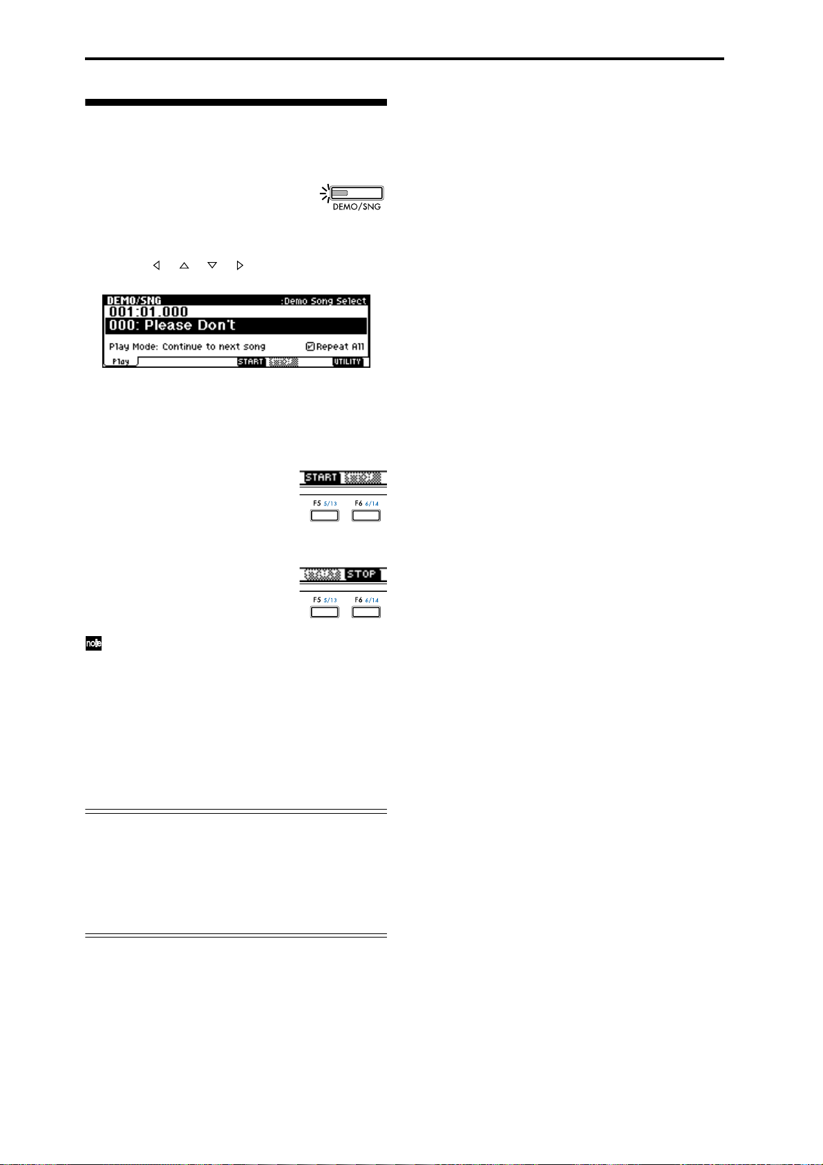
Listening to the demo songs
Here’s how to listen to the demo songs of the TRITONRack.
1 Press the [DEMO/SNG] key. (LED lit)
You will enter the Demo/Song, Play
page.
2 In “Demo Song Select,” select a demo song.
Use the [ ], [ ], [ ], [ ] keys to highlight a song
name in “Demo Song Select.”
3 Use the VALUE controllers ([VALUE] dial, [INC],
[DEC] keys, numeric keys [0]–[9] and the [ENTER]
key) to select the demo song that you wish to hear.
4 Press the [F5] (“START”) key.
Playback will begin.
5 To stop during playback, press the [F6] (“STOP”)
key.
If “Play Mode” is set to “Continue to next song,”
the next demo song will begin playing after the
currently selected demo song finishes playing. If
“Play Mode” is set to “Stop at end of selected
song,” playback will stop when the currently
selected demo song ends.
If “Play Mode” is “Continue to next song ,” check-
ing “Repeat All” will cause all songs to be played
back repeatedly.
Demo song “004: Deep Cut”
For the demo song “004: Deep Cut,” you can load the
included sampling data so that multisampled audio
will be played together with the demo playback.
As described in p.29 1, load the included sampling
data. Then select and play “004: Deep Cut” in the
Demo/Song, Play page.
16
Page 23

Quick Start
17
Page 24
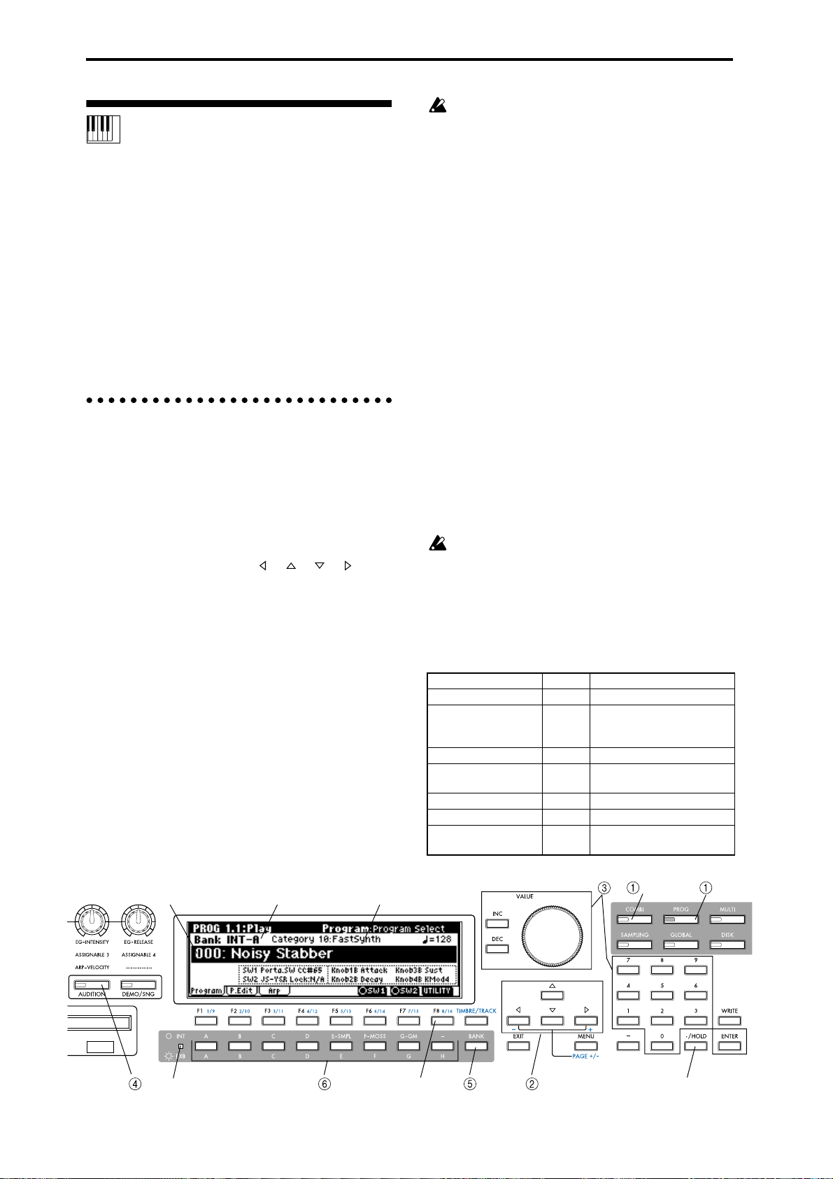
Playing from a MIDI keyboard (Program, Combina-
With the factory settings, the Audition function
can be used only on the preloaded programs of
banks INT-A–INT-D. and the preset programs G,
g(1)–g(d).
tion mode)
When you wish to play the TRITON-Rack from a MIDI
keyboard and take advantage of performance functions such as its realtime controllers or arpeggiator,
you should use Program and Combination modes.
The following section explains how to use Program
and Combination mode.
Before you begin trying the operations described here,
make the appropriate connections etc. as described in
the preceding chapter “Setup.” For “Connecting MIDI
equipment,” follow the instructions for “Connecting a
MIDI keyboard.”
1. Listening to the sound of a program
1 Press the [PROG] key. (LED lit)
You will enter Program mode. Make sure that the
upper line of the LCD screen indicates “PROG 1.1:
Play.”
Selecting a program number
2 Make sure that “Program Select” is selected.
If it is not selected, use the [ ], [ ], [ ], [ ] keys
to highlight the program name in “Program Select.”
3 Use the VALUE controllers to select the program
that you wish to play.
You can use the following methods to select a program.
• Rotate the [VALUE] dial.
• Press the [INC] or [DEC] key.
• Use numeric keys [0]–[9] to specify the number,
and press the [ENTER] key.
4 Audition the sound.
Play a note on the connected MIDI instrument to
hear the sound you selected.
Alternatively, you can press the [AUDITION] key
(the LED will light) to turn on the Audition function
and automatically play a riff (phrase) suitable for
the program.
Selecting a program bank
In Program mode you can select and play programs
from banks INT-A–g(d) and EXB-A–EXB-H. (
☞See the
table below.)
5 Press the [BANK] key to select INT banks or EXB
banks.
INT ([INT/EXB] LED dark): Pressing the [A]–[G]
keys will select banks INT-A–INT-F and G–g(d).
EXB ([INT/EXB] LED lit): Pressing the [A]–[H] keys
will select banks EXB-A–EXB-H.
6 Press one of the [A]–[H] keys to select a bank.
By changing banks you can select programs from
another bank.
With the factory settings, the INT-A–INT-D and G–
g(d) banks contain programs.
The selected bank number is shown in the left of the
LCD screen. For example if you wish to select bank
INT-B, press the [BANK] key to make the [INT/
EXB] LED go dark, and then press the [B] key. (The
upper left of the LCD screen will indicate Bank
INT-B.)
Bank INT-F can be selected if the separately sold
EXB-MOSS option is installed. When bank INT is
selected, the [H] key cannot be used.
When the [INT/EXB] LED is dark, repeatedly pressing the [G-GM] key will cycle through banks in the
following order.
G→g(1)→g(2)→g(3)→g(4)→g(5)→g(6)→g(7)→g(8)
→g(9)→g(d)→G
Bank Prog. No. Explanation
INT-A...INT-D (I-A...I-D) 000...127 Preloaded programs (
INT-E (I-E) 000...127 User programs (programs
INT-F (I-F) 000...127 EXB-MOSS programs
G 001...128 GM2 capital programs
g(1)...(9) (
g(d) (
EXB-A...EXB-H (E-A...E-H) 000...127 User programs, EXB-PCM
☞VNL) GM2 variation programs
☞VNL) GM2 drum programs
that use multisamples created in Sampling mode, etc.)
(
☞VNL)
series programs
☞VNL)
18
"Program Select"
INT/EXB
Bank No.
"Category"
UTILITY "Select by Category" Cat. HOLD, 10's HOLD
: Program : Combination
Page 25
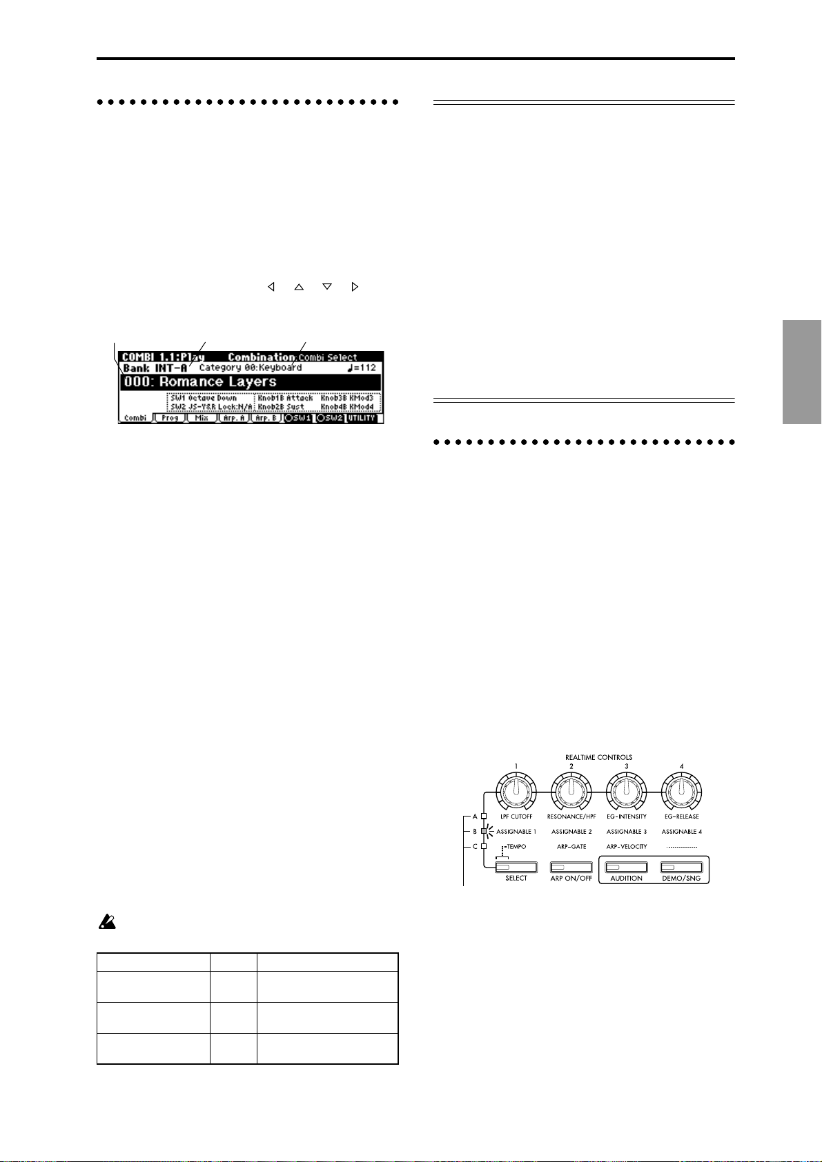
2. Listening to the sound of a combination
1 Press the [COMBI] key. (LED lit)
You will enter Combination mode. Make sure that
the upper line of the LCD screen indicates “COMBI
1.1: Play.”
Selecting a combination number
2 Make sure that “Combi Select” is selected.
If it is not selected, use the [ ], [ ], [ ], [ ] keys
to highlight the combination name in “Combi
Select.”
"Combi Select"
Bank No.
3 Use the VALUE controllers to select the combina-
tion that you wish to play.
☞“1. Listening to the sound of a program” 3
4 Audition the sound.
Play a note on the connected MIDI instrument to
hear the sound you selected.
Selecting a combination bank
In Combination mode, you can select and play combinations from banks INT-A–INT-E and EXB-A–EXB-H.
(
☞Table below)
5 Press the [BANK] key to select either INT banks or
EXB banks.
INT ([INT/EXB] LED dark): Pressing the [A]–[E]
keys will select banks INT-A–INT-E.
EXB ([INT/EXB] LED lit): Pressing the [A]–[H] keys
will select banks EXB-A–EXB-H.
6 Press one of the [A]–[H] keys to select a bank.
By changing banks you can select combinations
from another bank.
With the factory settings, the INT-A–INT-D banks
contain combinations.
The selected bank number is shown in the left of the
LCD screen. For example if you wish to select bank
INT-B, press the [BANK] key to make the [INT/
EXB] LED go dark, and then press the [B] key. (The
upper left of the LCD screen will indicate Bank
INT-B.)
When bank INT is selected, the [F]–[H] keys cannot be used.
Bank Prog. No. Explanation
INT-A...INT-D (I-A...I-D) 000...127 Preloaded combinations
INT-E (I-E) 000...127 User combinations, EXB-
EXB-A...EXB-H (E-A...E-H) 000...127 User combinations, EXB-
"Category"
☞VNL)
(
MOSS combinations
PCM series combinations
Other ways to select programs or combinations
Selecting by category
Programs or combinations can be selected from sixteen
categories.
With the factory settings, these are organized by instrument, such as keyboard, organ, bass, and drums.
(
☞PG p.2 “Cat.HOLD,” “Select by Category”)
Selecting with the 10’s Hold function
You can fix the 10’s place of the program number or
combination number, so that pressing a numeric key
once will change only the one’s place of the program
number and select it accordingly. (
☞PG p.2 “10’s
HOLD”)
Selecting from an external MIDI device
The TRITON-Rack can receive MIDI program change
messages from an external MIDI device to select programs. (
☞PG p.221)
3. Using controllers to modify the
sound
The TRITON-Rack provides numerous controllers that
allow you to control the tone, pitch, volume, effects,
and arpeggiator etc. in realtime while you play.
REALTIME CONTROLS [1], [2], [3], [4]
These knobs can be used to control the filter cutoff frequency and resonance, the amp and filter EG, volume,
portamento time, pan, pitch LFO, or the send levels to
the master effects, etc.
1 Press the [SELECT] key to switch the function of
the realtime controllers to A-mode, B-mode or Cmode.
Each time you press the key, A-mode, B-mode or Cmode will be selected alternately, and the corresponding LED will light.
The selected mode will light.
2 Rotate the desired knob to control the sound, etc.
A-mode controls
In A-mode, knobs [1]–[4] will control/edit the following functions.
Placing the knobs in the center (12 o’clock) position
will produce the values specified by the program
parameters.
Knob [1]: LPF CUTOFF
Adjusts the cutoff frequency of the low pass filter.
Quick Start
19
Page 26
When you adjust the cutoff frequency of the filter, the
brightness of the sound will change. The effect will
depend on the settings of the program parameters, but
normally, rotating the knob toward the left will darken
the sound, and rotating it toward the right will
brighten it.
Level
LPF
Frequency
Cutoff
frequency
HighLow
Knob [2]: RESONANCE/HPF
Adjusts the resonance level of a low pass filter or the
cutoff frequency of a high pass filter.
The content that is controlled will depend on the filter
type specified by the program.
By adjusting the filter resonance level, you can increase
or decrease the resonance level to add a unique character to the sound.
By adjusting the cutoff frequency of a high pass filter,
you can modify the brightness of the sound.
Level
LPF HPF
Cutoff
frequency
Knob [3]: EG-INTENSITY
Adjusts the filter EG intensity (the depth at which the
filter EG is applied).
Rotating the knob will affect the depth of the filter EG.
Normally, rotating the knob toward the left will make
the filter EG apply less deeply, and rotating it toward
the right will make the filter EG apply more deeply.
Since the filter EG will operate based on the cutoff frequency of the filter, knobs [1] and [3] will work
together to control the tonal changes produced by the
filter.
Level
Time
Knob [4]: EG-RELEASE
Adjust the EG release times of the filter and amp. This
will determine the time from note-off until the sound
disappears.
When you operate the knob, the release times of the filter EG and the amp EG will change. Normally, rotating
the knob toward the left will shorten the release time,
and rotating it toward the right will lengthen the
release time.
When the arpeggiator is running, it is effective to use
this in conjunction with the C-mode [ARP-GA TE] knob
to control the arpeggiated notes.
note-on
Level
Attack Level
Decay Time
Attack Time
Start Level
Break Level
Sustain Level
Slope Time
note-off
Release Time
Release Level
Time
B-mode controls
You can control parameters such as volume, portamento time, pan or filter and amp EG, pitch LFO, and
master effect send levels etc.
In each preloaded program, appropriate functions are
assigned to the B-mode knobs.
The B-mode function settings are made for each individual program, combination, or multi. In Sampling
mode, the B-mode functions are set for the entire
mode.
For details on making these settings (
☞p.100).
C-mode controls
You can control the arpeggiator in realtime. For details
on operation, refer to the following page.
Viewing the parameters that are assigned to the Bmode REALTIME CONTROLS and “SW1,” “SW2”
In Program, Combination, and Multi modes, the 1.1:
Play page lets you view the parameters that are
assigned to the B-mode of realtime control knobs [1],
[2], [3], and [4] and to “SW1” and “SW2.”
Functions assigned to
“SW1” and “SW2”
Functions assigned to
B-mode knobs [1]–[4]
“SW1” “SW2”
SW1, SW2
You can use these keys as sources for alternate modulation or effect dynamic modulation to control program
parameters or effect parameters.
These switches can also be used to turn portamento
on/off.
You can specify the way in which the “SW1” and
“SW2” will operate: either Toggle, when the assigned
function will be switched on/off each time the [F6],
[F7] key is pressed, or Momentary, when the assigned
function will be switched on only as long as you hold
down the key.
When you write a program or combination, the
on/off status of the “SW1” and “SW2” is saved.
For details on making these settings, refer to Setting the functions of “SW1” and “SW2” (
☞p.100).
20
Page 27
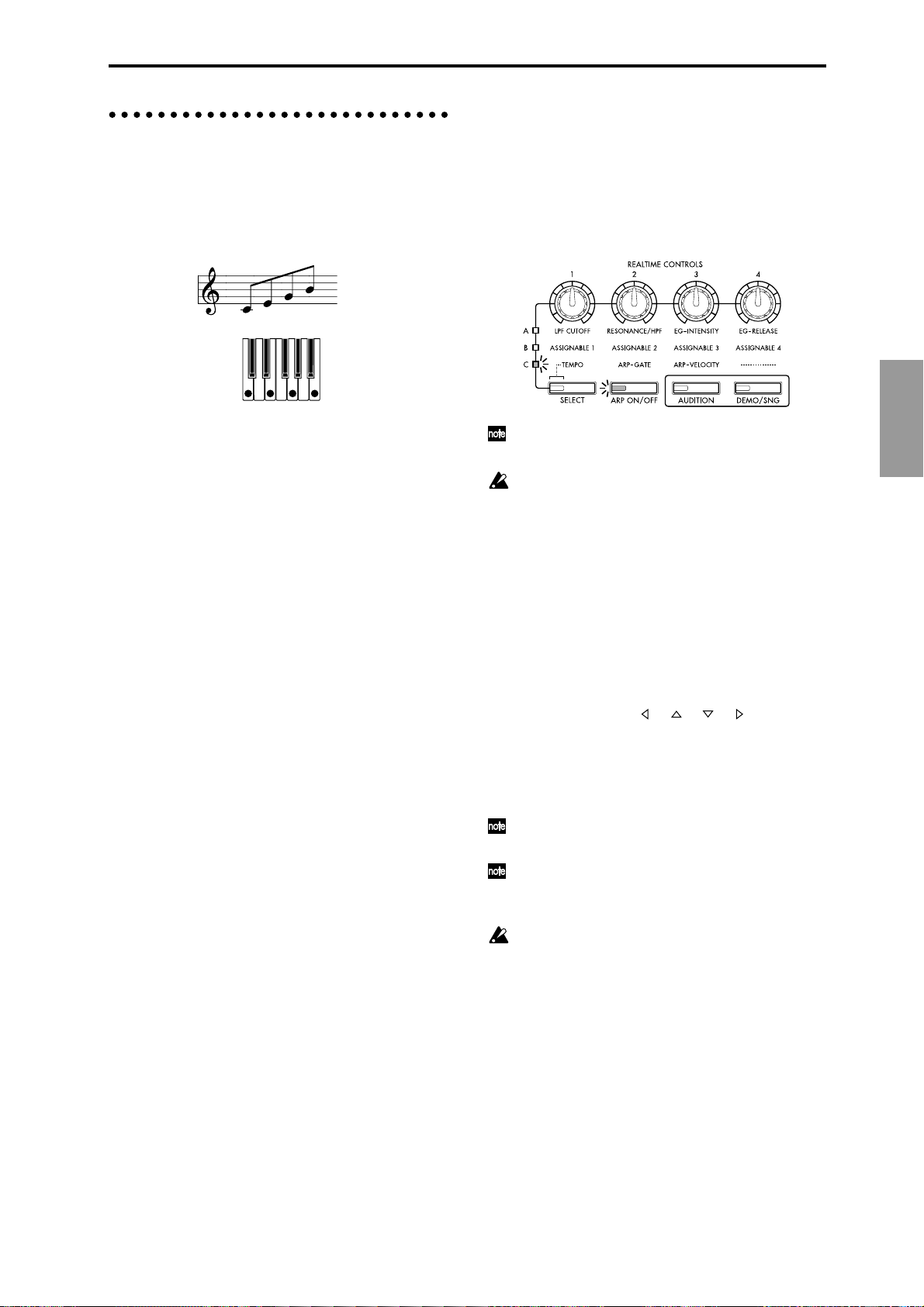
4. Using the arpeggiator while you
play
The arpeggiator is a function that automatically generates arpeggios (broken chords). Most arpeggiators produce an arpeggio when you play a chord on the
keyboard.
The chord you played on
the keyboard is sounded as
an arpeggio (broken chord)
Settings using controllers
Arpeggiator on/off
● Each time you press the [ARP ON/OFF] key, the
arpeggiator will be switched on/off.
When this is on, the LED will light, and playing the
keyboard of a connected MIDI instrument will start
the selected arpeggio pattern.
In addition to this, the TRITON-Rack’s arpeggiator is a
polyphonic arpeggiator that is able to produce a variety of chordal transformations or phrases based on the
pitch or timing of the notes you play on the keyboard.
These functions let you use the arpeggiator to play a
wide range of patterns including drum or bass
phrases, and guitar or keyboard backing riffs. It is also
effective to use the arpeggiator as part of the soundcreating process when creating subtly-moving pads,
synth-sounds, or sound effects.
In addition, the TRITON-Rack features a Dual Arpeggiator that lets you simultaneously use two arpeggio
patterns in Combination mode and Multi mode. You
can take advantage of this in many ways, such as
applying separate arpeggio patterns to a drums program and a bass program, or using keyboard split or
velocity to switch between two arpeggio patterns.
The TRITON-Rack provides five preset arpeggio patterns (the standard UP, DOWN, ALT1, ALT2, and
RANDOM), and lets you program and store 328 user
arpeggio patterns. With the factory settings, these contain a wide variety of preload user arpeggio patterns
(
☞VNL). An arpeggio pattern that you create can also
be stored as a user arpeggio pattern (
☞p.89).
Using the arpeggiator in Program mode
1 Press the [PROG] key to enter Program mode, and
select a program. (
of a program”)
As you select various programs, you will notice that
the [ARP ON/OFF] key LED will light for some
programs. (
tor”) Play the keyboard of the connected MIDI
instrument, and the arpeggio will start.
For other programs, you can press the [ARP ON/
OFF] key (the LED will light) to turn on the arpeggiator. Arpeggios will begin sounding when you
play the keyboard.
2 As described in the following sections “Settings
using controllers” and “Settings in the LCD
screen,” move the controllers or modify the parameters to change the way in which the arpeggios are
played.
☞p.18 “1. Listening to the sound
☞p.23 “Other settings for the arpeggia-
The on/off status is saved when you write the program, Combination.
In Combination and Multi modes, depending on
the arpeggiator A, B settings, the arpeggio may not
start when you press the [ARP ON/OFF] key to
turn it on (
Adjusting the arpeggiator tempo
1 Press the [SELECT] key to make the upper left “C”
LED light.
2 Rotate the [TEMPO] knob to adjust the tempo.
The “ =” value in the upper right of the LCD screen
will change. You can set this in the range of 40–240.
The [SELECT] key LED will blink at quarter-note ( )
intervals.
You can also use the [ ], [ ], [ ], [ ] keys to
select “ =,” input the tempo using numeric keys
[0]–[9], and press the [ENTER] key to set the tempo.
Alternatively, you can set the tempo using the
[VALUE] dial or the [INC], [DEC] keys. The tempo
will blink at the specified tempo.
The knob setting is saved when you write the program.
The arpeggio playback speed is affected by the
“Reso (Resolution)” setting (1.1: Play, Arp. Play
page, 6.1: Ed–Arp., Arpeg. Setup page).
If “MIDI Clock” (GLOBAL 2.1: MIDI) is set to
External, the display will indicate “ =” EXT. The
tempo will be synchronized to an external MIDI
device, and it will not be possible to adjust the
tempo on the TRITON-Rack.
Adjusting the length of the arpeggio notes
1 Press the [SELECT] key to make the upper left “C”
LED light.
2 Rotate the [ARP-GATE] knob to adjust the dura-
tion of the arpeggiated notes.
Rotating the knob toward the left will shorten the
notes, and rotating it toward the right will lengthen
the notes. At the center position (12 o’clock), the
note length will be as specified by the program
parameter “Gate” (6.1: Ed-Arp., Arpeg. Setup page).
☞p.23).
Quick Start
21
Page 28
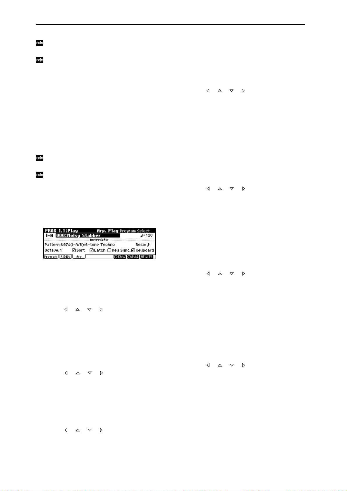
The knob setting is saved when you write the program.
You can control the effect by simultaneously
adjusting the A-mode [EG-RELEASE] knob.
Adjusting the strength of the arpeggio notes
1 Press the [SELECT] key to make the upper left “C”
LED light.
2 Rotate the [ARP-VELOCITY] knob to adjust the
strength of the arpeggiated notes.
Rotating the knob toward the left will make the
notes weaker, and rotating the knob toward the
right will make the notes stronger. At the center
position (12 o’clock), the velocity will be as specified
by the program parameter “Velocity” (6.1: Ed-Arp.,
Arpeg. Setup page).
The knob setting is saved when you write the program.
You can control the tone effectively by simultaneously adjusting the A-mode [LPF CUTOFF],
[RESONANCE/HPF], and [EG-INTENSITY]
knobs.
Settings in the LCD screen
● In PROG 1.1: Play, press the [F3] key to select the
Arp page.
Sounding an arpeggio in the order of the pitches in the
chord you played
You can select whether the notes of the arpeggio will
be sounded in the order of the pitches in the chord you
played (regardless of the order in which you actually
played the notes), or in the order in which you played
the notes.
● Use the [ ], [ ], [ ], [ ] keys to select the “Sort”
check box, and use the [VALUE] dial or the [INC],
[DEC] keys to make the setting.
Checked: the arpeggio will sound each note in the
order of its pitch, regardless of the order in which
you actually played the notes.
Unchecked: the arpeggio will sound each note in
the order in which you actually played the notes.
Letting the arpeggio continue playing even after you
take your hand off the keyboard
You can select whether the arpeggio will continue
playing when you take your hand off the keyboard, or
whether the arpeggio will stop playing when you take
your hand off the keyboard.
● Use the [ ], [ ], [ ], [ ] keys to select “Latch,”
and use the [VALUE] dial or the [INC], [DEC] keys
to make the setting.
Checked: The arpeggio will continue playing even
after you remove your hand from the keyboard.
Unchecked: The arpeggio will stop playing when
you remove your hand from the keyboard.
Selecting an arpeggio pattern
An arpeggio pattern can be selected from preset arpeggio patterns P000–P004 and user arpeggio patterns
U000 (I–A/B)–327 (E–H). With the factory settings,
U000–199 contain a wide variety of preset user arpeg-
gio patterns (
● Use the [ ], [ ], [ ], [ ] keys to select “Pattern,”
and use the [VALUE] dial or the [INC], [DEC] keys
to select the arpeggio pattern. To select a user arpeggio pattern, use numeric keys [0]–[9] to input the
pattern number, and press the [ENTER] key.
Changing the interval of the arpeggio notes
The “Reso (Resolution)” parameter in the LCD screen
lets you set the interval between arpeggio notes in a
range of 3 – .
● Use the [ ], [ ], [ ], [ ] keys to select “Reso,”
and use the [VALUE] dial or the [INC], [DEC] keys
to specify the spacing of the arpeggiated notes.
Selecting the octave range in which the arpeggio is
sounded
Use the “Octave” in the LCD screen to specify the
range of octaves in which the arpeggio will be sounded
(
☞p.86).
● Use the [ ], [ ], [ ], [ ] keys to select “Octave,”
and use the [VALUE] dial or [INC], [DEC] keys to
specify the range of octaves in which the arpeggio
will be sounded.
☞VNL)
Synchronizing the arpeggiator to your keyboard timing
You can specify whether the arpeggio will begin at the
moment you play the keyboard, or whether it will
always play in synchronization to the MIDI clock
tempo.
● Use the [ ], [ ], [ ], [ ] keys to select “Key
Sync.,” and use the [VALUE] dial or the [INC],
[DEC] keys to make the setting.
Checked: When you take your hand completely off
of the keyboard and then play the first note-on, the
arpeggio pattern will start from the beginning. This
setting is suitable when you want the arpeggio to
start from the beginning of the measure as you are
playing in realtime.
Unchecked: The arpeggio will always be synchronized to the MIDI clock tempo.
Sounding both the arpeggio notes and the notes you
play
● Use the [ ], [ ], [ ], [ ] keys to select “Key-
board” check box, and use the [VALUE] dial or the
[INC], [DEC] keys to make the setting.
Checked: The notes you play on the keyboard and
the notes played by the arpeggiator will both sound.
Unchecked: Only the arpeggio notes will sound.
22
Page 29

Using the arpeggiator as you play in Combination mode
In Combination mode the TRITON-Rack provides dual
arpeggiators, allowing you to run two arpeggio patterns simultaneously.
1 Press the [COMBI] key to enter Combination
mode, and select a combination. (
ing to the sound of a combination”)
As you select various combinations, you will notice
that the [ARP ON/OFF] key LED will light for some
combinations. (
tor”) When you press the keyboard, the arpeggiator
will start.
For other combinations, you can press the [ARP
ON/OFF] key (the LED will light) to turn on the
arpeggiator.
2 As described in the preceding section “Settings
using controllers” and the following section “Settings in the LCD screen,” move the controllers or
modify the parameters to change the way in which
the arpeggios are played.
The [ARP ON/OFF] key and the C-mode
[TEMPO], [ARP-GATE], and [ARP-VELOCITY]
knobs are valid for both arpeggiators A and B.
Their state will be memorized when the combination is written.
☞“Other settings for the arpeggia-
Settings in the LCD screen
● In COMBI 1.1: Play, press the [F4] key to select the
Arp. Play A page, and make settings for arpeggiator A.
In COMBI 1.1: Play, press the [F5] key to select the
Arp. Play B page, and make settings for arpeggiator B.
☞p.19 “2. Listen-
• As you can see from the “Timbre Assign” table in
the upper right, arpeggiator A is assigned to
timbre 4, and arpeggiator B is assigned to timbre 2.
When you play the keyboard of a connected MIDI
instrument, the U168 (I-A/B): BigBeats 1 arpeggio
pattern will play the program I-B068: Drum’n’Bass
Kit of timbre 4. The U096 (I-A/B): Stab Rhythm
arpeggio pattern will play the program I-B053:
Funkin’ Guitar of timbre 2.
• If you uncheck “Arpeggiator Run A” or
“Arpeggiator Run B,” the unchecked arpeggiator
will stop.
If you check it once again and play the keyboard,
the arpeggiator will begin running.
• Look at the COMBI 6.1: Ed-Arp., Zone page, and
you will see that the A keys “Btm” and “Top” are
set so that arpeggiator A will operate only for B3
and lower keys, and that the B “Top Key” and
“Bottom Key” are set so that arpeggiator B will
operate only for C4 and higher keys.
Quick Start
Select the arpeggiator(s) that will run
Use the “Arpeggiator Run” check boxes to specify the
arpeggiator(s) that you want to run. The arpeggiator(s)
that are checked here will operate when the [ARP ON/
OFF] key is on.
However , the arpeggiator will play a timbre only if the
table displayed beside the check boxes assigns arpeggiator A or B to a Ttimbre 1–8. These settings are made
in COMBI 6.1: Ed-Arp., Setup page “Assign” (
Arpeggiator-A, Arpeggiator-B
For each arpeggiator A and B, you can make settings
for “Pattern,” “Reso (Resolution),” “Octave,” “Sort,”
“Latch,” “Key Sync,” and “Keyboard.” (
☞p.87).
☞p.85)
Checking the structure of a user arpeggio pattern
Let’s see how combination I-B 063: Echo Jamm is constructed.
1 Select combination I–B 063: Echo Jamm, and look
at the Arp. Play A page and Arp. play B page.
Other settings for the arpeggiator
You can also set “Gate,” “Velocity,” “Swing,” and
“Scan Zone.” These parameters are set in PROG 6.1:
Ed–Arp, COMBI 6.1: Ed–Arp. (
☞p.85).
Linking the arpeggiator to program, combinations
You can specify whether the arpeggiator settings written in a program or combination will also be selected
when you switch programs or combinations, or
whether the arpeggiator status will not change when
you switch programs or combinations.
With the factory settings, the former is selected. Use
the latter when you want to keep the same arpeggio
pattern running, and change only the program sound.
This setting is made in “Auto Arp.” (GLOBAL 1.1: System, Basic).
Creating an user arpeggio pattern
Arpeggio patterns that you create can be written to
U000 (I–A/B)–327 (E–H).
These can be created in GLOBAL 6.1: Arp.Pattern
(
☞p.89).
23
Page 30
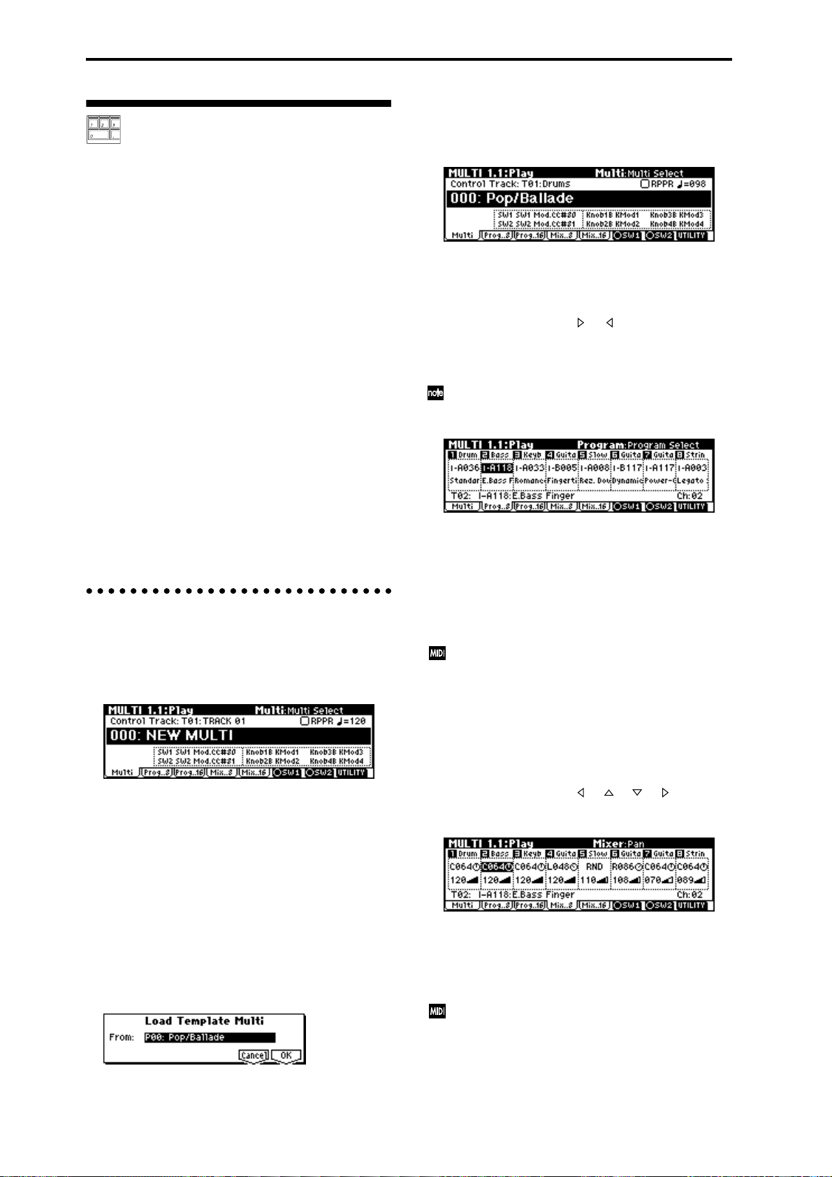
Playing with a computer/ sequencer (Multi mode)
Use Multi mode when you want the TRITON-Rack to
simultaneously play multiple tracks of musical data
sent from your computer/sequencer. This section
explains basic operation of Multi mode.
☞ For details on controlling the TRITON-Rack via
MIDI, refer to “MIDI applications” (
The TRITON-Rack can be used as a 16-channel multitimbral tone generator. It has 16 tracks, and a different
program sound can be assigned to each track. A track
is analogous to a musician in a band. In other words,
the TRITON-Rack is able to play up to 16-member
ensembles. For example, you might assign drums to
track 1, bass to track 2, and piano to track 3, etc.
Settings such as volume and pan can also be adjusted
independently for each track. In addition, the control
track lets you use the realtime controllers or “SW1”
and “SW2” to modify the sounds.
You can also use RPPR (Realtime Pattern Play/Recording) or the arpeggiator to perform in synchronization
with your computer/sequencer.
Before you continue, you should make connections as
described in the preceding chapter, “Setup.” For “Connecting MIDI equipment,” follow the example given
for “Connecting a sequencer (computer).”
1. Playing in Multi mode
1 Press the [MULTI] key. (LED lit)
You will enter Multi mode. Make sure that the
upper line of the LCD screen indicates “MULTI 1.1:
Play.”
2 Specify the program, pan, and volume that you
wish to use for each track.
You can use the “Load Template Multi” utility to
load program, pan, volume, and effect settings etc.
suitable for the desired style of music. Here we will
explain how to use a Template Multi to specify the
program, pan, and volume.
1) Press the [F8] (“UTILITY”) key to open the utility
menu.
2) Press the [F7] key to select “Load Template
Multi.”
3) Press the [F8] (“OK”) key to open the Load Template Multi dialog box.
☞PG p.221).
4) Use the [VALUE] dial or the [INC], [DEC] keys to
select the template multi that you wish to load.
For this example, let’s select P00: Pop/Ballade.
5) Press the [F8] (“OK”) key to load the template.
To change the programs of tracks 1–8, press the
[F2] (“Prog..8”) key. To change the programs of
tracks 9–16, press the [F3] (“Prog..16”) key.
P00: Pop/Ballade assigns the programs as shown
below. By pressing the [ ], [ ] keys you can select
the programs assigned to tracks 1–8.
The full name of the selected program is shown in
the bottom line.
You can directly select parameters by holding
down the [TIMBRE/TRACK] key and pressing the
nearest [F1]–[F8] key.
To change the program assigned to a track, select
the program of that track, and use the [BANK], [A]–
[H] keys, [VALUE] dial, [INC], [DEC] keys, numeric
keys [0]–[9] and the [ENTER] key to specify the
desired program. You can also use the “Select by
Category” utility to select programs by category.
(
☞PG p.2)
If a GM System On system exclusive message is
received, the TRITON-Rack will automatically be
reset to the GM settings.
To change the pan and volume settings of tracks 1–
8, press the [F4] (“Mix..8”) key. To change the pan
and volume settings of tracks 9–16, press the [F5]
(“Mix..16”) key.
P00: Pop/Ballade assigns pan and volume as shown
below. By pressing the [ ], [ ], [ ], [ ] keys you
can change the pan and volume specified for each
track 1–8.
To change the pan and volume settings of a track,
select the pan or volume of that track, and use the
[VALUE] dial, [INC], [DEC] keys, numeric keys [0]–
[9] and the [ENTER] key to specify the desired pan
or volume setting.
Program, pan, and volume can also be changed by
receiving the appropriate MIDI message transmitted from a sequencer (computer). (
3 Transmit musical data from your sequencer (com-
puter) to play the tracks.
☞PG p.221–)
24
Page 31

With the initial settings, tracks 1–16 correspond to
MIDI channels 1–16; i.e., track 1 receives MIDI channel 1, and track 2 receives MIDI channel 2, etc.
Using the RPPR (Realtime Pattern
Play/Recording) function
2. Controlling tracks from your computer/sequencer
MIDI transmit/receive channel
Set the MIDI transmit channel of your computer/
sequencer to match the “MIDI Channel” of the TRITON-Rack track that you wish to play.
When a track receives note data on a MIDI channel that
matches its own channel, the program of that track will
sound. MIDI messages such as control changes will
affect only the track that is receiving the corresponding
MIDI channel. The arpeggiator will operate when it
receives note data within the range of the Scan Zone
setting (
Operating the controllers of the TRITON-Rack will
control the sound etc. of the track that is selected for
“Control Track.”
Control of insert/master effect dynamic modulation or
the pan and send 1 and 2 that follow the insert effects is
performed on the MIDI channel specified for “Control
Channel” (7.2: Insert FX, Setup page). However, effect
on/off and exclusive data is received on the global
MIDI channel “MIDI Channel” (GLOBAL 2.1: MIDI).
(
Selecting the sound number of a part
To select the sound number of a track from your computer/sequencer, transmit a program change message
on the MIDI channel for the corresponding track.
To change the bank, you will have to transmit control
change #0 and 32 bank select messages. The TRITONRack will not change the program sound immediately
when a bank select message is received. The program
sound of the specified bank will be selected when the
program change message is received following the
bank select message.
Transmit bank select [Bn, 00, mm] (control change #00)
and [Bn, 20, bb] (control change #32) (mm: upper byte
of the bank number, bb: lower byte of the bank number, n: channel) and program change [Cn, pp] (pp: program/combination number). Transmission and
reception of bank select messages will vary, depending
on the “Bank Map” (GLOBAL 1.1: System, Pref) setting. (
☞PG p.68) on the MIDI channel of the track.
☞PG p.221)
☞PG p.109)
The functionality for transmitting and specifying
bank select and program numbers will differ
depending on your sequencer or sequencer software. Refer to the owner’s manual for your
sequencer or sequencer software for details on
operation.
The Multi mode of the TRITON-Rack provides an
RPPR (Realtime Pattern Play/Recording) function.
RPPR is a function in which pattern data and a track
that will play it can be assigned to each note of the keyboard, allowing you to play patterns in realtime simply
by pressing a note on a connected MIDI keyboard.
(Internal memory contains preset patterns that are
appropriate for use with drum tracks.)
Here’s how to load and play the RPPR demo .SNG
data.
1 Load “RPPRDEMO.SNG” from the included
“TNRFD-00P” floppy disk.
1) Insert the included “TNRFD-00P” floppy disk
into the floppy disk drive.
2) Press the [DISK] key (LED lit) to enter Disk
mode.
3) Press the [F1] (“Load”) key to select the Load
page.
4) Use the [ ], [ ] keys to select
“RPPRDEMO.SNG.”
5) Press the [F8] (“UTILITY”) key to access the utility menu.
6) Use the [F7] key to choose “Load Selected,” and
press the [F8] (“OK”) key. The following dialog
box will appear.
7) For “.SNG Allocation,” select Clear.
If you load with Clear selected, the multi data in
memory will be erased. (
8) Press the [F8] (“OK”) key to load the data.
Never remove the media while data is being
loaded.
If the “Memory Protected” dialog box appears,
uncheck the memory protect setting, and load the
data once again. (
2 Make sure that 000: FEVER is selected in Multi
mode.
1) Press the [MULTI] key (LED lit) to enter Multi
mode.
2) Press the [F1] (“Multi”) key to select the Multi
page.
☞PG p.126)
☞p.37)
Quick Start
25
Page 32

000: FEVER will be displayed.
3 Make sure that the RPPR check box is checked.
Checked: The selected RPPR (the setting of 5.1:
RPPR, RPPR Setup) will operate.
Unchecked: RPPR will not operate. This is the normal state of Multi mode.
4 Set the “Control Track” MIDI channel and the
channel of the transmitting MIDI device to the
same setting.
In the illustration above, track 1 is the control track.
Since track 1 of 000: FEVER is set to MIDI channel 1,
set the transmitting MIDI device to MIDI channel 1.
5 Start playing patterns via RPPR.
For example if the transmitting MIDI device is a
MIDI keyboard, pressing any key C#2 or above will
start the pattern that is assigned to that key.
Sometimes the pattern will continue playing even
after you release the key, but in such cases you can
stop the pattern by playing the same key once again
or by playing C2 or a lower key.
Simple program editing
Program sounds can be modified and created in PROG
2.1: Ed-Basic–7.3: Ed-MasterFx. However, you can also
use the “Performance Editor” to perform simple editing in PROG 1.1: Play Perform. Edit page as well.
Y ou can also use REALTIME CONTROLS [1]–[4] knobs
to modify the sound.
Program editing refers to the process of modifying the
parameters that make up a program, in order to modify the sound or change the controller or effect settings.
The sound that you edit using the Performance
Editor or using REALTIME CONTROLS knobs
[1]–[4] in A-mode (or B-mode if CC#70–79 are
assigned) can be saved by writing the program.
The edits you make will be lost if you select
another program or turn off the power. If you wish
to keep your edited data, you must write it into
memory. (
Performance Edit
1 Press the [PROG] key (LED lit) to enter Program
mode.
2 Press the [F2] (“P.Edit”) key.
The Perform. Edit page will appear.
☞p.37)
Shutdown Keys *:
When you play a key in the range of C–1 – C2, the currently-playing pattern will stop.
Pattern Assignable **:
A pattern and track can be assigned to each of the 72
keys in the range of C#2–C8. If you do not assign a key,
it can be used to play as usual.
As in the example shown in the following diagram,
you can make one key play a drums pattern, another
key a bass phrase, and yet another key play guitar
chords, all by specifying a different pattern and track
for each key.
88 keys (TRITON proX)
76 keys (TRITON pro)
61 keys (TRITON)
C-1
Shutdown Keys *
C-1 ... C2
Pattern P000 Track01 (Drums Program)
Pattern U000 Track02 (Bass Program)
Pattern P001 Track01 (Drums Program)
Pattern U001 Track02 (Bass Program)
Pattern U002 Track03 (Guitar Program)
Pattern Assignable **
C#2 ... C 8
G9
Performance Editor
3 Use the Performance Editor to adjust the sound.
Use the [ ], [ ], [ ], [ ] keys to select the
desired performance editor slider, and use the
[VALUE] dial or the [INC], [DEC] keys to adjust the
setting.
By using the eight sliders of the Performance Editor ,
you can make overall adjustments to the sound.
When you move a slider, multiple program parameters are adjusted simultaneously.
Depending on the settings of the program parameters, the result may not be noticeable.
Octave
Adjust the octave.
Pitch Stretch
Simultaneously adjust the transpose and tune settings
of the oscillator. This allows you to produce a variety
of tonal changes without losing the character of the
original sound.
This Performance Edit function cannot be used on
bank I–F.
26
Page 33

OSC Balance
Adjusts the level balance between oscillators 1 and 2.
For programs whose “Mode (Oscillator Mode)”
(PROG 2.1: Ed-Basic, Prog Basic page) setting is
Single, oscillator 2 will not sound. Only the level
of oscillator 1 will change. For a Drums program,
this performance editor will have no effect.
Amp Level
Adjusts the amp level. This will adjust the volume of
the entire program.
Attack Time
Adjusts the attack time of the filter EG and amp EG.
This will adjust the speed of the attack from note-on.
In order to maximize the effect of the Attack Time
adjustment, the amp EG Start Level, Attack Level,
Start Level Modulation, and Attack Time Modulation parameters are also adjusted.
Decay Time
Adjusts the decay time and slope time of the filter EG
and amp EG.
IFX Balance
This simultaneously adjusts the “W/D (Wet/Dry)”
balance of all insert effects 1–5.
MFX Balance
This simultaneously adjusts the Return 1 and 2 parameters of the master effects.
Realtime controls
These can be used to edit parameters such as the filter
cutoff frequency, resonance, the amp and filter EG, volume, portamento time, pan, pitch LFO, and master
effect send level etc. (
☞p.19).
Simple combination editing
A combination is a set of multiple (up to eight) programs, and allows you to create complex sounds that
could not be produced by a single program.
Combination editing is the process of modifying the
parameters that make up the combination in order to
change the program used by each timbre, to change the
keyboard range or velocity values that sound each timbre, or to make controller settings etc.
You can edit a combination in COMBI 2.1: Ed-Prog/
Mix–7.3: Ed-MasterFX, but can also make settings for
“Program Select, “Pan,” and “Volume” in COMBI 1.1
Play as well.
The edits you make will be lost if you select
another combination or turn off the power. If you
wish to keep your edited data, you must write it
into memory. (
An example of editing
As an example, here’s how to do some simple editing
on combination Bank I–A064: ModernPiano.
1 Press the [COMBI] key (LED lit) to enter Combina-
tion mode.
2 Select Bank I–A064: ModernPiano.
This combination layers (simultaneously sounds)
the programs of timbre 1 and timbre 2. Timbre 1
sounds I–B001: Attack Piano, a piano with a crisp
attack. Timbre 2 sounds I–B081: Vintage EP, a clas-
sic electric piano. These two programs are layered to
produce a piano-type sound that you may have
heard in various contexts.
A timbre consists a of program together with mul-
tiple parameters that control that program. A combination can use up to eight of these timbres.
☞p.37)
Quick Start
Selecting the program for a timbre
3 Press the Prog page.
Press the [F2] (“Prog”) key. Now you can specify the
programs for timbres 1–8.
4 Now let’s change the program of timbre 2 to a dif-
ferent program.
Use the [ ], [ ], [ ], [ ] keys to select “Program
Select” for timbre 2 (it will be highlighted).
Timbre 2Timbre 1
You can directly select the program for a timbre by
holding down the [TIMBRE/TRACK] key and
pressing the nearest [F1]–[F8] key. Similarly in
steps 6 and 7, you can select pan or volume in
the same way.
“Program Select”
27
Page 34

For this example, select I-A003: Legato Strings . This
is a layered combination with piano and rich
strings. Make sure that the [INT/EXB] LED is dark.
(If it is lit, press the [BANK] key.) Then consecutively press the [A] key, the [3] key, and the [ENTER]
key.
Alternatively, the program for a timbre can be
selected by category.
Choose “Program Select,” press the [F8] (“UTILITY”) to access the utility menu, and press the [F7]
key to choose “Select by Category.” Press the [F8]
(“OK”) key.
The Select Program by Category dialog box will
appear.
Choose “Cat” and use the [INC], [DEC] keys to
select the category. For example if you wish to select
strings programs instead of the “00: Keyboard” cat-
egory shown in the screen above, press the [INC]
key three times to select “03: Strings.”
You can use the [ ], [ ] keys to successively select
string-type programs.
When you are happy with the selected program,
press the [F8] (“OK”) key to finalize your selection.
Listening to the program sound of just one timbre
Use the [VALUE] dial, the [INC], [DEC] keys, or
numeric keys [0]–[9] and the [ENTER] key to
change the value.
A setting of C064 is center, L001 is far left, and R127
is far right. With a setting of RND, the stereo loca-
tion will change randomly between left and right
each time a note is played.
Adjusting the volume
7 Adjust the “Volume” of timbre 2.
Use the [ ], [ ], [ ], [ ] keys to choose “Volume” (highlighted) for timbre 2.
Use the [VALUE] dial, the [INC], [DEC] keys, or
numeric keys [0]–[9] and the [ENTER] key to
change the value.
Adjusting the volume while preserving the volume
balance between timbres
● Press the [F8] (“UTILITY”) key to access the utility
menu, and press the [F7] key to choose “Hold Balance.” Press the [F8] (“OK”) key. The upper right of
the LCD screen will indicate “Hold Bal.”
When you change the “Volume” value of any timbre, the volume of all timbres will also change to
preserve the volume balance at the time you
checked the Hold Balance setting.
To cancel this setting, choose “Hold Balance” once
again and press the [F8] (“OK”) key.
● Press the [F8] (“UTILITY”) key to access the utility
menu, and press the [F7] key to choose “Solo
Selected Timbre.” Press the [F8] (“OK”) key.
Now you will hear only the program sound of the
currently selected timbre. The lower part of the LCD
screen will indicate [Solo]. To cancel this setting,
choose “Solo Selected Timbre” once again and press
the [F8] (“OK”) key.
Adjusting the stereo location of the sound
5 Select the Mixer page.
Press the [F3] (“Mix”) key. Here you can adjust the
pan and volume for timbres 1–8.
6 Adjust the stereo location in “Pan” of timbre 2.
Use the [ ], [ ], [ ], [ ] keys to choose “Pan”
(highlighted) for timbre 2.
28
Page 35

Listening to sampled sounds
Here’s how to load demo multisample data and play it
back in Sampling mode.
1 Load “DCUT_SMP.KSC” from the included
“TNRFD-01P” floppy disk.
1) Insert the included “TNRFD-01P” floppy disk
into the floppy disk drive.
2) Press the [DISK] key (LED lit) to enter Disk
mode.
3) Press the [F1] (“Load”) key to select the Load
page.
4) Use the [ ], [ ] keys to select
“DCUT_SMP.KSC”
5) Press the [F8] (“UTILITY”) key to access the utility menu.
6) Press the [F7] key to choose “Load Selected,” and
press the [F8] (“OK”) key. The following dialog
box will appear.
7) For this example, select Clear for “.KSC Allocation”
When you select Clear and then load, the multisample data and sample data of Sampling mode
will be erased (
8) Press the [F8] (“OK”) key to load the data.
☞PG p.130).
3 Set the channel of the transmitting MIDI device to
match the global MIDI channel.
With the factory settings, the global MIDI channel is
set to channel 1. Set the transmitting MIDI device to
MIDI channel 1.
4 Play the samples of the multisample.
For example if the transmitting MIDI device is a
MIDI keyboard, play any note in the range of C2,
D2–F#2 to sound the sample that is assigned to that
key.
You can also press the [AUDITION] key to hear the
sample played. For “Index,” use the [INC][DEC]
keys to select another sample for assignment to the
multisample, and press the [AUDITION] key.
Using a multisample in a program
Multisample data you sampled in Sampling mode or
sample/multisample data you loaded in Disk mode
can be converted to a program by executing the “Conv.
To Prog” utility. (
Alternatively, a multisample you created in Sampling
mode can be assigned to the Program mode parameters “High MS Bank” and “High Multisample” or
“Low MS Bank” and “Low Multisample,” and used as
a program.
When a multisample you created in Sampling mode is
used as a program, you will be able to process its
sound in various ways by using the filter and effects of
the program.
By selecting the preloaded program I-E 000: Sampler
Waves, you can listen to the various samples of a program that uses the multisample you heard in step 4.
You can hear the result of using the compressor or
delay etc. to process the sound of the multisample.
Samples can be used in a drum kit.
☞p.32, PG p.83)
☞p.78
Quick Start
Never remove the media while data is being
loaded.
2 Make sure that multisample 000: Gospel Vocal L is
selected in Sampling mode.
1) Press the [SAMPLING] key (LED lit) to enter
Sampling mode.
2) If SMPL 1.1: Recording is not selected, press the
[EXIT] key.
3) Press the [F1] (“Sample”) key to select the Sample page.
4) If 000: Gospel Vocal L is not selected, use the [ ],
[ ], [ ], [ ] keys to choose “Multisample
Select,” and use the [INC], [DEC] keys to select it.
The multisamples and samples of Sampling mode
will disappear when the power is turned off. If
you wish to use them after turning the power on
once again, you must reload them.
Sampling (recording a sample)
Here’s how you can use Sampling mode to sample a
drum phrase from an audio CD etc., and convert it into
a program.
1. Sample a drum phrase
Y ou will need to pr ovide a r hythm loop sample such as
a drum phrase from a CD or other audio source. To
start with, let’s use a rhythm loop sample with a relatively simple beat.
As an example here, we will sample two one-measure
drum phrases in 4/4 time at 140 BPM and 100 BPM.
29
Page 36

Connect your external audio device and
make input settings
TRITON-Rack
CD player
L
LINE OUT
R
1 Connect the AUDIO INPUT 1, 2 jacks on the rear
panel of the TRITON-Rack to the AUX OUT L and
R jacks of your CD player.
2 Set the AUDIO INPUT [MIC/LINE] switch to the
LINE position.
3 Press the [SAMPLING] key (LED lit) to enter Sam-
pling mode.
If SMPL 1.1: Recording is not selected, press the
[EXIT] key.
4 Press the [F3] (“In/Pref”) key to select the Input/
Pref page.
5 Set various parameters so that the signal from the
AUDIO INPUT jacks will be input to the TRITON-Rack.
Make the following settings.
• Input 1: “Lvl” 127, “Pan” L000, “BUS” L/R
• Input 2: “Lvl” 127, “Pan” R127, “BUS” L/R
When you change the setting from Off to L/R or
IFX1–5, the volume level of the AUDIO OUT L/
MONO and R jacks or the headphone volume may
rise abruptly. Please use caution.
Manual sampling
There are two ways to record a sample: manual and
auto. In this example we will use manual sampling.
7 Press the [F2] (“Rec.”) key to access the Recording
page.
8 Set “Mode (REC Mode)” to Manual
This will select manual recording mode.
9 Set “Mode (Sample Mode)” to Stereo.
0 Press the [F4] (“REC”) key.
When an input sound is present, the “Recording
Level” L and R meters will move. The TRITONRack is in recording standby condition.
Set “Recording Level” to +0.0.
A At the moment that you wish to start sampling,
press the [F5] (“START”) key.
Sampling will start.
It is a good idea to allow a bit of extra time before
you start and after you stop sampling.
B At the moment that you wish to stop sampling,
press the [F5] (“STOP”) key.
Sampling will stop.
Sampling will stop automatically if the remaining
amount of memory reaches zero.
C Listen to the sound you sampled.
Press the [AUDITION] key or play the C2 note on a
connected MIDI keyboard, and you will hear the
sound that was sampled.
This completes sampling for the 140 BPM drum
phrase. Now repeat steps 0–B to sample the 100
BPM drum phrase.
With these settings, the sound from the AUDIO
INPUT 1 and 2 jacks will be output in stereo from
the AUDIO OUTPUT L/MONO and R jacks, and
from the headphones. The sound from AUDIO
INPUT 1 will be output from the L side, and 2 from
the R side.
6 Adjust the [INPUT] knob to set an appropriate
input level.
Adjust the [INPUT] knob or the output level of the
external audio device so that the level just avoids
triggering the “ADC OVER!” display (i.e., the highest possible level that does not produce an overload).
If an overload occurs in the input stage of the TRITON-Rack, an indication of “ADC OVER!” (AD
converter input overload!) will appear at the right
of the level meter.
30
2. Assign samples to a multisample
1 Press the [F1] (“Sample”) key to access the Sample
page.
2 Assign the first sample in “SMPL.”
Press the [ ] key to select “SMPL,” and use the
[DEC] key to select 0000:NewSample_0000-L (the
140 BPM drum phrase).
Page 37

3 Press the [F6] (“CREATE”) key to create another
index.
Currently selected index/Total
Index2Index1
number of indexes
1 Select 3.1: Loop Edit.
Press the [MENU] key to open the page menu, and
press the [F3] key. Press the [F8] (“Open”) key.
4 Assign the second sample in “SMPL.”
Select “SMPL,” and press the [INC] key to select
0002: NewSample_0002-L (the 100 BPM drum
phrase).
5 Listen to the samples that you assigned to the mul-
tisample.
Press the C2 key on a connected MIDI keyboard and
the 140 BPM drum phrase sample will play. Press
the C3 key and the 100 BPM drum sample will play.
6 Assign a name to each sample.
Choose “Index” in the upper right of the LCD
screen, and press the [DEC] key to select 001.
Press the [F8] (“UTILITY”) key to access the utility
menu, and press the [F7] key to choose “Rename
SMPL.” Press the [F8] (“OK”) key to open the
Rename Sample dialog box.
Press the [F5] (“Name”) key to open the text dialog
box.
Let’s name the 140 BPM drum phrase LOOP1-
140BPM.
Press the [F1] (“Clear”) key. Now we will input the
first character, “L.” Use the [VALUE] dial, [INC],
[DEC], or [ ], [ ], [ ], [ ] keys to select “L.”
Press the [F6] key and input the second character.
Use the [VALUE] dial, [INC], [DEC], or [ ], [ ],
[ ], [ ] keys to select “O.” Repeat these steps to
input all the characters, and then press the [F8]
(“OK”) key twice (
☞p.38).
2 Select “Index” 001, and make sure that “SMPL” is
set to 0000: LOOP1-140BPM-L.
3 Press the [F2] (“Edit2”) key to access the Edit2
page.
The waveform data of the currently selected sample
will be displayed.
Quick Start
The selected sample is a stereo sample. The L and
R waveforms will be displayed alternately when
you press the [F3] (“L/R”) key.
4 Use “S (Start)” to set the start address, “LpS (Loop
Start)” to set the loop start address, and “E (End)”
to set the end address.
The sample will sound as follows.
When looping is on: S → E → LpS → E → (continue
repeating LpS → E)
When looping is off: S → E
Use the [ ], [ ] to select “S (Start)” (highlighted),
and use the [VALUE] dial etc. to specify the location
at which the sample will begin sounding. The vertical line in the display will move accordingly.
As necessary, you can press the [F4]–[F7] keys to
expand or shrink the waveform display. Zoom will
expand/shrink the display starting at the selected
“S (Start),” “LpS (Loop Start),” or “E (End)”
points.
Next, let’s name the 100 BPM drum phrase LOOP2-
100BPM.
Select “Index,” press the [INC] key to select 002, and
use “Rename SMPL” to assign a name using the
same procedure as above.
3. Make loop settings
Next we will delete unwanted portions from the sample, and make settings so that the sample will be
looped smoothly.
By default when the power is turned on, sampled
sounds will be looped automatically. (1.1: Recording, Input/Pref page “Auto Loop On ” On)
If you check “Zero (Use Zero),” locations where
the waveform is at zero will automatically be
found and selected when you use the [VALUE]
dial etc. to set “S (Start),” “LpS (Loop Start),” or “E
(End)” points. This makes it easy to set these
points to addresses that will not produce clicks or
noise.
For this example, set “LpS (Loop Start)” and “S
(Start)” to the same value.
If desired, you can make a dotted vertical line
appear in the sample waveform display to indicate
the BPM. If you use this function with waveforms
that have a specific BPM, it will be easier to make
accurate settings for “E (End).”
31
Page 38

Press the [F8] (“UTILITY”) key to access the utility
menu, and press the [F7] key to select “Grid.”
Press the [F8] (“OK”) key. The following dialog
box will appear.
Check “Grid,” set “Resolution” to , and press the
[F8] (“OK”) key. Set “ (Grid Tempo)” to 140. With
these settings, vertical dotted lines will be displayed at 140 BPM quarter note intervals.
Set “E (End).”
When “Lp (Loop)” is On, the dotted vertical “Grid”
lines will start at “LpS (Loop Start).” If you want to
set “End” at the end of one 4/4 measure, the fourth
vertical line from the “LpS (Loop Start)” line will be
the end of the first measure. Place “E (End)” at this
vertical line.
4. Convert to a program
Next we will convert the samples and multisample to a
program.
1 Press the [F1] (“Edit1”) key to access the Edit1
page.
Alternatively, you may also use the 1.1: Recording
page.
2 Execute the “Conv. To Prog” utility.
Press the [F8] (“UTILITY”) key to access the utility
menu, and press the [F7] key to select “Conv. To
Prog.” Press the [F8] (“OK”) key. The following dialog box will appear.
In “To,” specify the conversion destination program. In the above illustration, the I-E005 initial
program has been selected.
If you execute the Convert operation with “Use Destination Program Parameter” unchecked, the sound
as it was in Sampling mode will be created as a program. If you wish to use the program parameters of
a preloaded program (I-A 000–I-D 127), and execute
this operation with “Use Destination Program
Parameters” checked.
5 Use “Truncate” to delete the unwanted data that is
outside of the start (or loop start) and end
addresses.
Press the [F8] (“UTILITY”) key to access the utility
menu, and press the [F7] key to select “Truncate.”
Press the [F8] (“OK”) key. The following dialog box
will appear.
Set “Truncate” to Front & End. In this example, we
will not change the settings of the “Save to No.” and
“Overwrite” check boxes, so press the [F8] (“OK”)
key to execute. When you execute the operation, the
truncated samples 0004: LOOP1-140B0004-L and
0005: LOOP1-140B0004-R will be automatically
assigned to Index 1.
Please refer to “A note on saving samples” (
for a cautionary note regarding the “Save to No.”
and “Overwrite” check boxes.
6 In the Edit1 page, select “Index” 002, make sure
that “SMPL” is set to 0002:LOOP2-100BPM-L, and
repeat steps 3–5 to make loop settings for the 100
BPM sample.
☞p.73)
When you execute the Convert operation, the convert destination (“To”) program will be overwritten, and replaced by the converted program.
If you wish to execute the conversion with “Use
Destination Program Parameters” checked for a
stereo multisample, you must first set the convert
destination (“To”) program “Mode (Oscillator
Mode)” parameter to Double in the PROG 2.1: EdBasic, Prog Basic page.
If necessary, press the [F5] (“Name”) key to access
the text dialog box, and assign a program name.
Press the [F8] (“OK”) key. A dialog box will appear,
asking you for confirmation. Press the [F8] (“OK”)
key once again to execute the conversion.
3 Listen to the converted program.
Move to Program mode, select the program (I-E 005
in this example), and play the keyboard etc. of the
connected MIDI instrument to hear the sound.
The sample and multisample data you create will
be lost when you turn off the power, but a converted program will automatically be written into
internal memory. If you wish to reproduce these
settings after you turn on the power again, you
will need to first save the samples or multisamples
to external media in Disk mode. Then after turning
on the power again, load the data with Clear
selected for the “.KSC Allocation” parameter.
W e r ecommend that you use “Save All” to save the
data, so that the samples, multisamples, and the
converted programs are saved together. When you
load, load the data together in the same way.
☞p.40, PG p.134)
(
32
Page 39

Basic functions
33
Page 40

Basic operation of the TRITON-Rack
Selecting modes, pages and tabs;
setting parameters
1. Selecting modes
● In order to use a particular function on the TRI-
TON-Rack, you must first select the appropriate
mode. Press one of the front panel mode keys
([COMBI] key – [DISK] key) to enter the corresponding mode.
[COMBI] key: Combination mode
[PROG] key: Program mode
[MULTI] key: Multi mode
[SAMPLING] key: Sampling mode
[GLOBAL] key: Global mode
[DISK] key: Disk mode
In Disk mode there is only one page, so the page
menu will not appear.
3 Press the function key [F1]–[F7] that is nearest the
page you wish to select.
If multiple pages are assigned to one function key,
press the same key to move the cursor downward.
Y ou can also use the [ ], [ ], [ ], [ ] cursor keys
to move.
4 Press the [F8] (“Open”) key.
When you press the [F8] key, you will jump to the
selected page, and that page will appear.
As an example here, press the [F3] key three times to
select “KeyZ,” and then press the [F8] (“Open”) key.
The 3.3: Ed-Key Zone page will appear.
2. Selecting pages and tabs
Each mode has a large number of parameters, which
are grouped into pages. Each page is further divided
into as many as seven groups. These are referred to as
“tabs.”
Selecting a page
1 Make sure that the desired mode is selected.
To select a mode, press the appropriate mode key
([COMBI] – [DISK]). Here we will use Combination
mode as an example for our explanation. Press the
[COMBI] key.
2 Press the [MENU] key.
The page menu will appear.
Y ou can also use the following alternative methods
to select a page.
• Press the [MENU] key, and then use the [ ], [ ]
keys to move forward or backward through the
pages in the order of 1.1→2.1→2.2→2.3 etc.
• Hold down the [MENU] key, and use numeric keys
[0]–[9] to enter a two-digit page number to move
directly to the corresponding page. (To select the
page shown above, you would press [3], [3].)
The page selected at this time will be the page that was
last selected. If there is no corresponding page, nothing
will happen.
When you press the [EXIT] key, you will return to
1.1 from any page.
Selecting a tab
5 Press the function key [F1]–[F7] that is nearest the
tab displayed at the bottom of the LCD screen.
As an example here, we will select the “Review” tab.
Press the [F5] key.
• Some pages have no tabs.
6 To move to another page, press the [MENU] key
and repeat the procedure from step 3.
34
Page 41
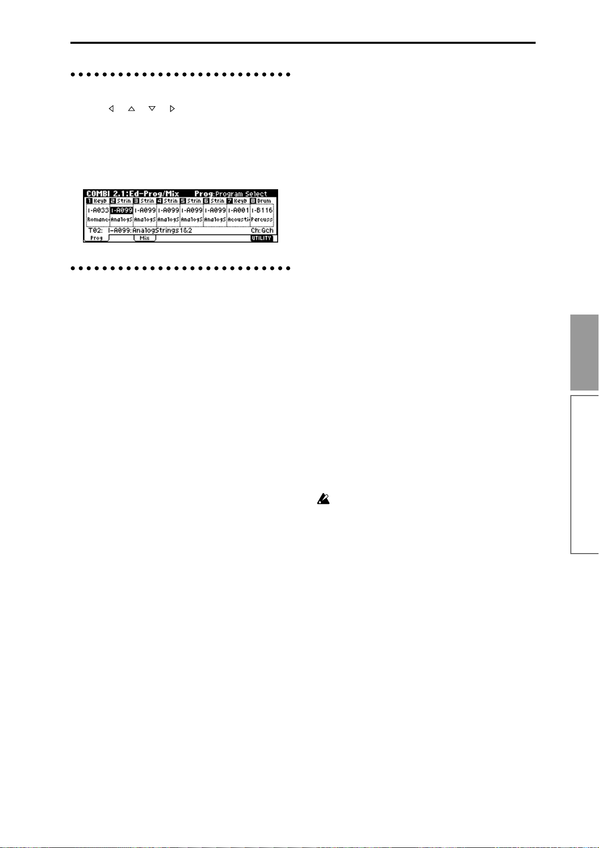
3. Selecting parameters
Use the [ ], [ ], [ ], [ ] cursor keys to select the
parameter that you wish to edit.
In Combination mode pages that display timbres 1–8,
or in Multi mode pages that display tracks 1–8 or 9–16,
you can hold down the [TIMBRE/TRACK] key and
press the nearest function key [F1]–[F8] to select the
desired timbre or track.
4. Setting a parameter
The parameter value in the edit cell can be set by using
the front panel VALUE controllers ([INC] key, [DEC]
key, [VALUE] dial, numeric keys [0]–[9], [–] key, [./
HOLD] key, and [ENTER] key). As necessary, you can
also use the [BANK] keys, [A]–[H] keys, and the
[COMPARE] key.
In the case of parameters that require you to enter a
note or velocity value, you can enter the value by playing a key on a connected MIDI keyboard while holding
down the [ENTER] key.
VALUE controllers
[VALUE] dial
Use this when you wish to make large changes in a
value.
[INC] key, [DEC] key
Use these when you wish to make fine adjustments to
the value.
Numeric keys [0]–[9], [ENTER] key, [–] key,
[./HOLD] key
Use these when you know the parameter value that
you wish to input.
After using the numeric keys [0]–[9] to input a number ,
press the [ENTER] key to finalize the parameter value.
Use the [–] key to enter negative numbers.
Use the [./HOLD] key to enter a decimal point. In Program and Combination mode 1.1: Play page, the [./
HOLD] key performs the 10’s Hold function. (
32)
[BANK] keys, [A]–[H] keys
The [BANK] keys and [A]–[H] keys are used in Program mode to select the program bank and in Combination mode to select the combination bank. In
Combination mode, they are also used to select the program bank for each timbre of the combination. In Multi
mode, these keys are used to select the bank of the program used by each track of the multi.
These keys are also used to specify the bank in dialog
boxes such as Write Program or Write Combination.
☞PG p.2,
[COMPARE] key
Use this key when you wish to compare an edited program or combination sound with the un-edited origi-
nal (i.e., the sound that is written into memory).
When editing a program or combination, press this key.
The LED will light, and the last-written settings for that
program number or combination number will be
recalled. When you press the [COMPARE] key once
again, the LED will go dark and you will return to the
settings that you were editing etc.
If you edit the settings that are recalled by pressing the
[COMPARE] key (i.e., the settings that are written into
memory), the LED will go dark, and it will not be possible to return to the previous settings by pressing the
[COMPARE] key again.
In Multi mode, the [COMPARE] key is used to compare the “before” and “after” states of pattern realtime
recording, step recording, or event editing.
As an example, here’s how you can use Compare when
recording a pattern in realtime.
1 Realtime-record a pattern. (Take 1)
2 Once again, realtime-record on the same pattern.
(Take 2)
3 Press the [COMPARE] key. The LED will light, and
take 1 will be recalled.
4 Press the [COMPARE] key once again. The LED will
go dark, and take 2 will be recalled.
5 If at step 3 you once again realtime-record on the
same pattern (take 3), the object of the Compare
function will now be take 1. If at step 4 you once
again realtime-record on the same pattern (take 3),
the object of the Compare function will be take 2.
In this way, the Compare function lets you recall the
previous recording or the previous state of event editing.
The Compare function is not available in Sampling
or Global modes.
Keyboard input
When inputting a note name or velocity value as the
value of a parameter , you can use a key on a connected
MIDI instrument to input the setting. Hold down the
[ENTER] key and play the note that you wish to enter
as a value. The note name (number) or velocity value
will be input.
When the GLOBAL 5.1: DKit page or MULTI 5.1:
RPPR, RPPR Setup page is displayed, you can hold
down the [ENTER] key and play a note to recall the settings that have been assigned to the note you played.
In Sampling mode, you can hold down the [ENTER]
key and play a note to recall the index that is assigned
to the note you played.
Basic functions
Basic operation of the TRITON-Rack
35
Page 42

Saving data
Types of data that can be saved
On the TRITON-Rack, there are three ways to save
data: writing to internal memory, saving on external
media (floppy disk etc.), and MIDI data dump.
Writing to internal memory
The following data that you edit can be written into
internal memory.
• Program
Programs 0–127 in banks I-A–I-F, E-A–E-H (However , bank I-F is available only if the separately sold
EXB-MOSS option is installed.)
• Combination
Combinations 0–127 in banks I-A–I-E, E-A–E-H
• Global settings (1.1–4.1 page)
• User drum kits 000(I-A/B)–143(E-H)
• User arpeggio patterns U000(I-A/B)–U327(E-H)
• User template multis U00–U15
Song settings such as the multi name and tempo
etc., track settings (☞p.58), arpeggiator settings, and
effect settings can be saved (Write) to internal memory.
Use the Multi mode Utility “Save Template Multi”
to write this data (
If multisamples or samples from the RAM bank
are used in the Multisample or Drum Kit of a pro-
gram, you should be aware that these multisamples or samples cannot be written into memory.
This means that if you turn the power off and then
on once again, programs or combinations that use
such multisamples or samples will not sound as
intended. To reproduce such programs or combinations, the necessary multisamples or samples
must be saved on external media (such as floppy
disk), and then reloaded.
User pattern and RPPR settings for a multi in Multi
mode and the various settings of Sampling mode
cannot be written into internal memory by the
Write operation.
DEMO/SNG song data that you loaded can be written
into internal memory. Execute the Disk mode utility
“Load to Demo Song” to write this data. (☞p.42, PG
p.132)
☞PG p.51).
Saving to external media (floppy disk etc.)
The following data can be saved on external media
(floppy disk etc.). If the separately sold EXB-SCSI
option is installed, this data can also be saved on highcapacity media such as a hard disk etc.
For details on the file format when saving (
• Programs, combinations, global settings, user
drum kits, and user arpeggio patterns from
internal memory
• Multi and user patterns
• Multisamples and sample data created in
Sampling mode
• Standard MIDI Files (SMF)
Save one pattern of Multi mode as SMF data.
• System exclusive data
System exclusive data received by the TRITONRack from an external MIDI device (The TRITONRack can function as a data filer.)
☞PG p.133).
MIDI data dump
The following types of data can be transmitted as a
MIDI data dump and saved on an external data filer or
other device.
• Internal memory programs, combinations, global
settings, user drum kits, and user arpeggio
patterns
• Multis, user patterns
About preloaded data and preset data
Preloaded data is the data that is loaded into memory
at the factory. This data can be rewritten, and is written
into the various locations listed in the preceding section “Writing to internal memory.” This data is also
stored on the included floppy disk.
• Program banks INT-A–INT-D: 000–127, INT-E: 000–
002
• Combination banks INT-A–INT-D: 000–127
• User drum kits 000 (I-A/B)–015 (I-A/B)
• User arpeggio patterns U000 (I-A/B)–U199 (I-A/B)
• Demo songs 000–004
Preset data is data that cannot be rewritten by the
Write operation. This includes the following data.
• Program banks G, g(1)–g(9), g(d) 001–128
• Preset drum kits 144 (GM)–152 (GM)
• Preset arpeggio patterns P000-P004
• Preset template multis P00–P15
• Preset patterns P000–P149
• Program audio riffs 001–382
36
Page 43

Writing to internal memory
Memory protect
To prevent programs, combinations, multis, drum kits
and user arpeggio patterns from being overwritten
accidentally, the TRITON-Rack provides a Memory
Protect setting that prohibits writing to memory.
Before you save edited data or load data from floppy
disk or other external media, use the following procedure to turn off memory protect (uncheck the appropriate check box).
Y ou should also turn memory pr otect off if you want to
load the above data from external media or via MIDI
data dump, or if you wish to record or edit patterns in
Multi mode.
1 Press the [GLOBAL] key to enter Global mode
(LED lit), and press the [EXIT] key to select 1.1:
System.
2 Press the [F2] (“Pref.”) key to access the 1.1: Sys-
tem, Preferences page.
3 Uncheck the appropriate “Memory Protect” check
box for the data that you wish to write into internal
memory.
Writing a program or combination
The programs or combinations that you create by using
the Performance Editor or by editing parameters in the
various edit (Ed) pages can be saved in the internal
memory of the TRITON-Rack. This action is referred to
as “writing a program” or “writing a combination.” If
you want your edited data to be preserved after the
power is turned off, you must write it.
There are two ways to write a program or combination.
Before you write data into memory, you must turn
off the memory protect setting in Global mode.
(
☞“Memory protect”)
The screen shown is for Program mode
2 In “Category,” specify the category of the program/
combination.
If the category you specify here is for a program,
you can use it when selecting by category in the Cat.
Hold function or the “Select by Category” utility in
PROG 1.1: Play, “Program Select” in the COMBI 1.1:
Play, Prog page, the COMBI 2.1: Ed-Prog/Mix.Prog
page, or the MULTI 1.1: Play, Program page utility
“Select by Category.”
In the case of a Combination, the category you specify here can be selected when you use the “Select by
Category” utility or the Cat. Hold function in
COMBI 1.1: Play: (“Combi Select”).
3 Use “To” to specify the bank and number of the
writing destination program/combination.
Use the [VALUE] dial, [BANK], [A]–[H], [INC],
[DEC] keys, or numeric keys [0]–[9] and the
[ENTER] key to specify the destination.
4 If you wish to change the name of the program/
combination, press the [F5] (“Name”) key.
The text dialog box will appear. Input the name of
the program/combination.
(Rename)”
After you have input the name, press the [F8]
(“OK”) key to return to the Write Program/Write
Combination dialog box.
5 To execute the Write operation, press the [F8]
(“OK”) key. To cancel without executing press the
[F7] (“Cancel”) key.
When you press the [F8] (“OK”) key, the display
will ask “Are you sure?” When you press the [F8]
(“OK”) key once again, the data will be written.
☞“Assigning a name
Using the [WRITE] key to write
This method can only be used to write to the selected
program/combination number.
1 Press the [WRITE] key.
The following dialog box will appear.
The screen shown is for Program mode
Basic functions
Saving data
Using a Utility menu command to write
1 Select the Utility “Write Program” or “Write Com-
bination.”
The Write Program/Write Combination dialog box
will appear.
Y ou can also access the same dialog box by holding
down the [ENTER] key and pressing the [0] key.
2 To write the data, press the [F8] (“OK”) key. To
cancel without writing, press the [F7] (“Cancel”)
key.
37
Page 44
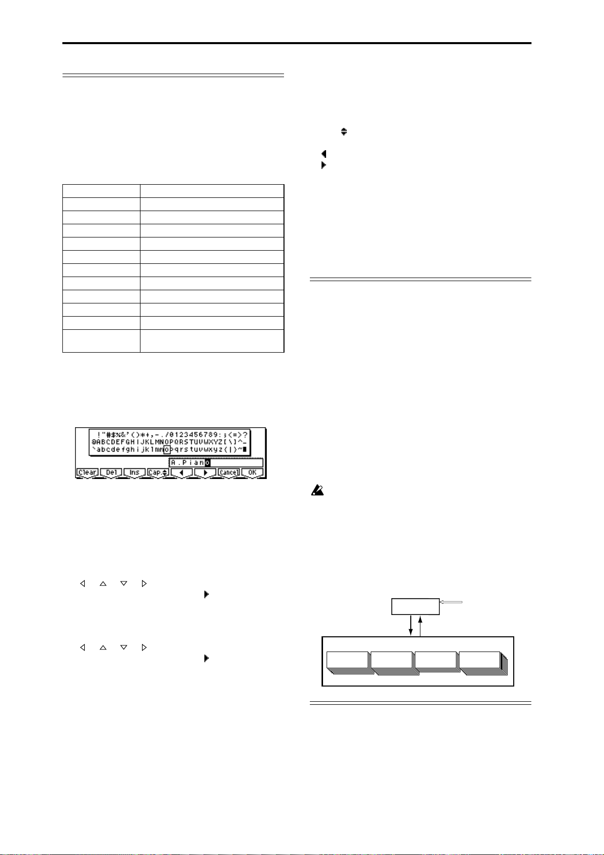
Assigning a name (Rename)
You can modify the name of an edited program, combination, multi, drum kit, user arpeggio pattern, multisample or sample etc.
You can also modify the category names for programs
and combinations.
These renaming operations can be performed in the
following pages.
Programs PROG 1.1...7.3 Utility: Write Program
Combinations COMBI 1.1...7.3 Utility: Write Combination
Multis MULTI 1.1...4.4, 6.1 Utility: Rename Multi
Tracks MULTI 1.1, 5.1 Utility: Rename Track
Patterns MULTI 5.1 Utility: Rename Pattern
Multisamples SMPL 1.1...4.1, 5.2 Utility: Rename MS
Samples SMPL 1.1...4.1, 5.2 Utility: Rename SMPL
Drum kits GLOBAL 5.1 Utility: Rename Drum Kit
User arpeggio patterns GLOBAL 6.1 Utility: Rename Arpeggio Pattern
Program categories GLOBAL 4.1: TEXT
Combination categories GLOBAL 4.1: TEXT
File DISK, Save Utility: Save All...Export Smpl AIF/
WAV
1 Open the text dialog box.
Refer to the above table for the relevant page.
In the utility commands, press “Name” (the [F5]
key) in the dialog box that appears.
In GLOBAL 4.1, select “TEXT” (press the [F5] key).
The function buttons will have the following functions.
Clear: Erase all text.
Del (Delete): Delete the character at the cursor loca-
tion.
Ins (Insert): Insert a space at the cursor location.
Cap. (Capital): Switch between uppercase and
lowercase letters.
: Move the cursor to the left.
: Move the cursor to the right.
The following input operations can also be
performed.
“0”–“9,” “–,” and “.” can be input using the numeric
keys. When you input these, the cursor will advance
automatically.
To input successive spaces (blanks), press the
[ENTER] key at the last-selected text.
About the Edit Buffer
When you select a program or combination in PROG
1.1: Play and COMBI 1.1: Play, the program or combi-
nation data is called into the “edit buffer.”
When you modify the parameters in 1.1: Play or in the
edit pages 2.1–7.3 of Program mode or Combination
mode, the changes you make will affect the data in the
edit buffer.
If you wish to save this modified data into internal
memory, you must perform the Write operation.
When you perform the W rite operation, the data in the
edit buffer is written to the specified program number
or combination number of the specified bank.
If you select another program or combination without
writing, the data of the newly selected program or
combination will be called into the edit buffer, and
your changes will be lost.
For example if you wish to input the text shown in
the screen shown above, you would use the following procedure.
2 Press the [F1] (“Clear”) key.
All text of the text box will be erased.
3 Input “A”
Use the [VALUE] dial, the [INC], [DEC] keys, or
[ ], [ ], [ ], [ ] keys to select “A.”
Press the [ENTER] key or [F6] (“ ”) key. The cursor
will move.
4 Input “.”
Use the [VALUE] dial, the [INC], [DEC] keys, or
[ ], [ ], [ ], [ ] keys to select “.”
Press the [ENTER] key or [F6] (“ ”) key. The cursor
will move.
Repeat this step to input all the characters.
5 Press the [F8] (“OK”) key.
If you selected “Name” in the dialog box of step 1
to access the text dialog box, you will return to the
previous dialog box. Press the [F8] (“OK”) key in
that dialog box to execute the Rename operation.
If you selected “TEXT” in step 1 to access the text
dialog box, the Rename operation will be executed.
When you press the [COMPARE] key in the edit
pages 2.1–7.3 of Program mode or Combination
mode, the data from memory (i.e., the contents
that were written into memory) will be temporarily called into the edit buffer. This allows you to
compare the settings you are editing with the original un-edited settings.
Editing applies to the data in the edit
buffer. Programs or combinations will
play according to the data in the edit
buffer.
Edit
When you select a program or
combination, its data is called from
internal memory into the edit buffer.
Combination
Bank EXB-A 0...127
When you write, the program or
combination settings will be
saved in internal memory.
Program
Bank INT-A 0...127
Bank EXB-A 0...127
Edit Buffer
Write
Internal Memory
Program
Select
Combination
Bank INT-A 0...127
38
Page 45
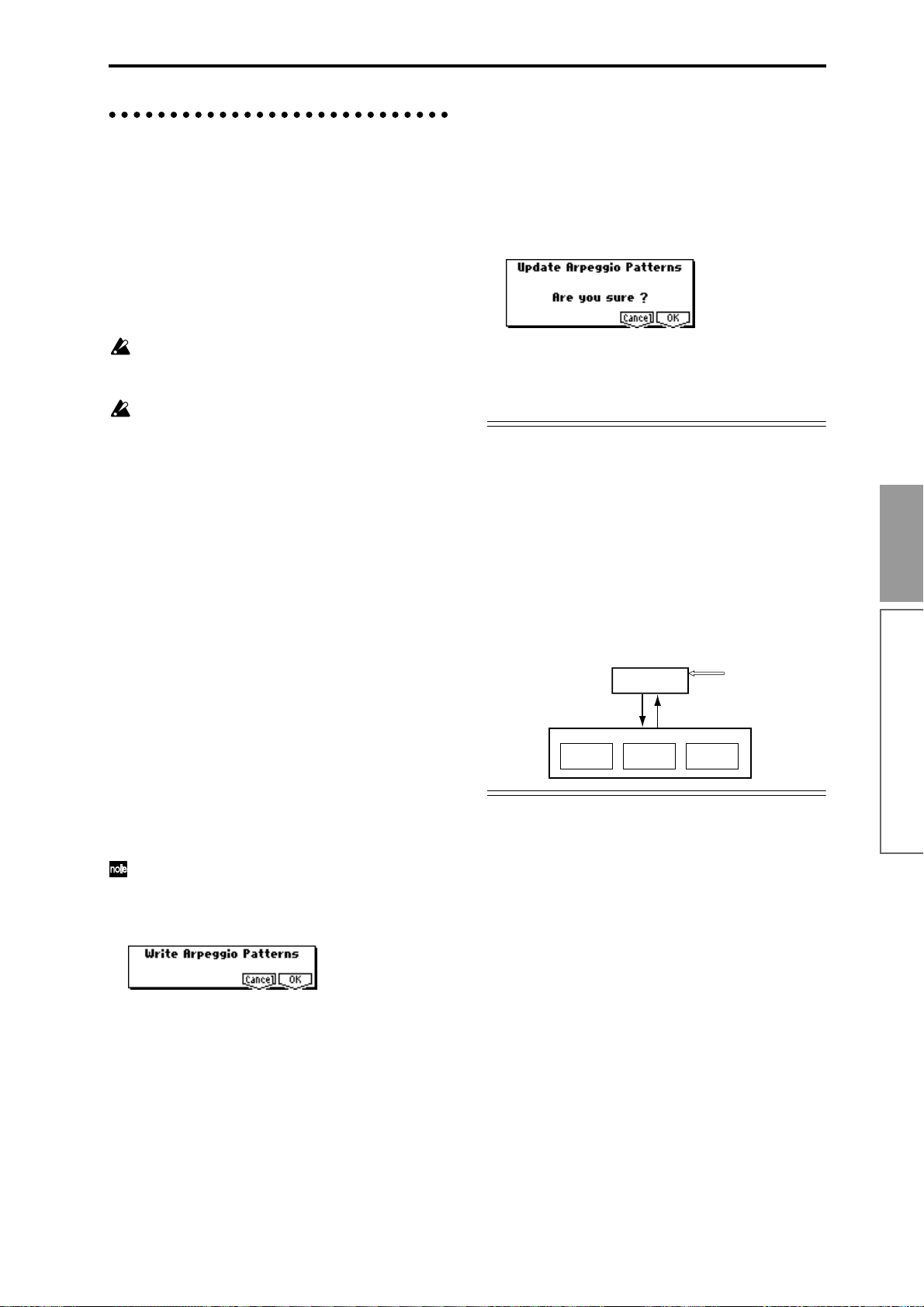
Writing global settings, user drum kits,
and user arpeggio patterns
The settings you edit in Global mode can be written
into internal memory . This is done using the operations
Write Global Setting, Write User Drum Kits, and
W rite User Arpeggio Patterns. If you wish to use these
settings after turning the power off, be sure to write the
data.
There are two ways to write global settings, user drum
kits, and user arpeggio patterns.
Using the [WRITE] key to write
1 In the following pages, press the [WRITE] key. A
dialog box will appear.
Global settings: GLOBAL 1.1–4.1
User drum kits: GLOBAL 5.1
User arpeggio patterns: GLOBAL 6.1
The example shown is for Update Arpeggio Patterns
Before you write a user drum kit or user arpeggio
pattern, the Global mode memory protect setting
must be turned off (
☞“Memory protect”).
The user arpeggio pattern settings “Tempo,” “Pattern,” “Octave,” “Resolution,” “Sort,” “Latch,”
“Key Sync,” and “Keyboard” are parameters that
are set independently in Program, Combination,
and Multi mode. These settings are not saved
when you perform the Write operation described
here.
If you moved from Program or Combination mode
and set these parameters, you must return to the
original mode and write them.
Using a Utility menu command to write
1 To write global settings (the various settings in
GLOBAL 1.1–4.1), select the “Write Global Setting” utility in GLOBAL 1.1–4.1, and press the [F8]
(“OK”) key.
The Write Global Setting dialog box will appear.
To write user drum kits, select the Utility “Write
Drum Kits” in GLOBAL 5.1, and press the [F8]
(“OK”) key.
The Write Drum Kits dialog box will appear.
To write user arpeggio patterns, select the Utility
“Write Arpeggio Patterns” in GLOBAL 6.1, and
press the [F8] (“OK”) key.
The Write Arpeggio Patterns dialog box will appear.
2 To execute the Write operation, press the [F8]
(“OK”) key. To cancel, press the [F7] (“Cancel”)
key.
Memory in Global mode
When the power is turned on, the Global mode data is
called from internal memory into the Global mode
memory area. Then when you modify the parameters
in Global mode, the data in the memory area will be
modified. If you wish to save this modified data in
internal memory, you must write it.
When you write, the data in the memory area will be
written into the global settings, drum kits, and arpeggio patterns of internal memory.
If you turn off the power without writing, the modified
data in the memory area will be lost.
Editing will affect the data that has
When you write, the various
Global mode settings will be
saved in internal memory.
Global Setting
been called into the memory area.
Memory Area
Write
Power On
Internal Memory
Drum Kit
Edit
When the power is turned
on, the settings are called
into the memory area.
Arpeggio
Pattern
Basic functions
Saving data
The same dialog box will also appear if, in each of
the above pages, you hold down the [ENTER] key
and press the [0] key.
The example shown is for Write Arpeggio Patterns
2 To execute the Write operation, press the [F8]
(“OK”) key. To cancel, press the [F7] (“Cancel”)
key.
When you press the [F8] (“OK”) key, the display
will ask “Are you sure?” Press the [F8] (“OK”) key
once again to write the data.
39
Page 46

Saving on external media
For details on the data that can be saved on external
media (floppy disk etc.) (☞p.36 “Types of data that can
be saved”).
6 Select the “Save All” utility.
The user patterns or RPPR settings of Multi mode
and the multisamples and samples of Sampling
mode cannot be written into internal memory. This
data will disappear when the power is turned off.
If you wish to keep this data, you must save it on a
floppy disk or on other external SCSI storage
media (if the separately sold EXB-SCSI option is
installed).
Other types of data can also be saved on a floppy
disk, or (if the separately sold EXB-SCSI option is
installed) on external SCSI storage media (maximum 4 GB), and loaded to restore the original settings even if they have been modified. It is a good
idea to save favorite settings that you create.
As an example, we will explain how to save the
following data.
• Internal memory programs, combinations, global
settings, user drum kits, user arpeggio patterns
• Multi, user patterns
• Multisamples and samples created in Sampling
mode
Multiple floppy disks may be required to save all
requested data.
1 If you wish to save the data on a floppy disk, insert
a floppy disk into the TRITON-Rack’s floppy disk
drive.
For details on floppy disk handling, be sure to refer
to “Cautions when handling floppy disks” (☞p.84).
If the separately sold EXB-SCSI option is installed
and you wish to save the data on a hard disk or
other external SCSI media, refer to the EXB-SCSI
owner’s manual, and make sure that the external
SCSI drive etc. is connected correctly.
Format the disk if necessary (
2 Press the [DISK] key. You will enter Disk mode.
☞PG p.137)
Press the [F8] (“UTILITY”) key to access the utility
menu. Press the [F7] key to select “Save All,” and
then press the [F8] (“OK”) key.
A dialog box will appear. The contents of the dialog
box and the settings etc. will differ depending on the
type of data that you are saving. For details on each
type of file (
7 Press the [F5] (“Name”) key to access the text dia-
log box, and input the name. ☞p.38
8 Press the [F6] (“S.Item”) key, and un-check the
items that you do not need to save.
Select item
Use “Select Item” to select Prog Bank, Combi Bank,
Drum Kit, or Arpeggio Pattern, and select the items
(banks) that you wish to save. The items whose
check boxes are checked will be saved. After making
your selection(s), press the [F8] (“OK”) key.
9 Press the [F8] (“OK”) key to execute the Save oper-
ation.
If the data fits on one volume of media
The data will be saved on the specified media, and
you will return to the Save page. The amount of
time required will depend on the amount of data.
If a file with the same name already exists on the
floppy disk, you will be asked whether you want to
overwrite. If you wish to overwriting, press the [F8]
(“OK”) key. If you wish to save without overwriting,
press the [F7] (“Cancel”) key, re-do the operation from
step 6, and rename the data in step 7 before saving it.
☞PG p.133).
Drive Select
3 Press the [F2] (“Save”) key to access the Save page.
4 When saving to external SCSI media, choose Drive
Select, and specify the save destination drive.
5 If the media contains directories, select the direc-
tory in which you wish to save the data.
To move to a lower directory level, press the [F6]
(“OPEN”) key. To move to a higher level, press the
[F5] (“UP”) key.
40
If the data does not fit on one volume of media
(floppy disk)
The “No space available on medium” dialog box
will appear. (
Y ou can divide the file and save the data on multiple
volumes of media. If you do not want to divide the
data, press the [F7] (“Cancel”) key, and re-save the
data on media that has more free area or on a different drive (if the separately sold EXB-SCSI option is
installed).
☞PG p.133)
Page 47

1) Make sure that you have a sufficient number of
floppy disks, and press the [F8] (“OK”) key. Saving will begin.
2) When the disk is full, the following dialog box
will appear.
Other ways to save
In addition to “Save All,” the Utility menu commands
include “Save PCG” which saves programs, combinations, drum kits, user arpeggio patterns, and global settings; “Save Multi” which saves only multi and user
patterns; and “Save Sampling Data” which saves only
multisamples and samples. Select the appropriate Utility menu command for the data that you wish to save
on external media.
3) Insert the next floppy disk into the TRITONRack’s floppy disk drive.
4) Press a function key etc. to make the TRITONRack detect the next floppy disk.
5) Press the [F8] (“Select”) key. Saving will begin.
6) If the “No Space available on medium” dialog
box appears again, repeat steps 1)–5).
If you decide to cancel the Save operation, press
the [F7] (“Cancel”) key.
The dialog box of step 2) will appear. Press the
[F7] (“Cancel”) key will appear.
The display will ask “Are you sure?” Press the
[F8] (“OK”) key. This will cancel the Save operation.
7) When saving is complete, you will return to the
Save page.
0 When saving ends and you return to the Save
page, the LCD screen will show the file that was
saved.
The data will be saved as the following files.
.PCG file
Programs, combinations, drum kits, user arpeggio
patterns, and global settings that were saved in
internal memory
.SNG file
Multi and user patterns
.KSC file
A file which lists the multisamples and samples
used
Directory
A directory containing the multisamples (.KMP
files) and samples (.KSF files) that are listed in the
.KSC file
When using “Save All,” “Save PCG & Multi,” and
“Save PCG” to save combinations, you should also
remember to save the programs used by each timbre (and the drum kits used by the programs) and
user arpeggio patterns at the same time.
Similarly when saving programs, you should also
remember to save the drum kits and user arpeggio
patterns used by the programs.
If your programs or drum kits use multisamples
and samples that were created in Sampling mode,
we recommend that you use “Save All” to save the
data.
When you use “Save PCG” or “Save Sampling
Data” to individually save a program or drum kit,
or a multisample or sample that you created in
Sampling mode, we recommend that you save
them under the same filename in the same directory.
When you use “Load PCG” to load a .PCG file, the
identically-named .KSC file will also be loaded so
that the correct multisamples/samples will correspond automatically.
MIDI data dump
The programs (I-A–I-F, E-A–E-H)), combinations (I-A–
I-E, E-A–E-H), drum kits, arpeggio patterns and global
settings of internal memory, and multi and user arpeggio patterns can be transmitted as MIDI exclusive data
and saved on a connected MIDI data filer , computer, or
another TRITON-Rack. (
☞PG p.113)
Basic functions
Saving data
When loading files that were saved across multiple
volumes of media, a “Where is a ...” dialog box will
appear during the loading process. Insert the disk
containing the specified file, select the directory,
and press the [F8] (“Select”) key to load the data.
(
☞PG p.125)
41
Page 48
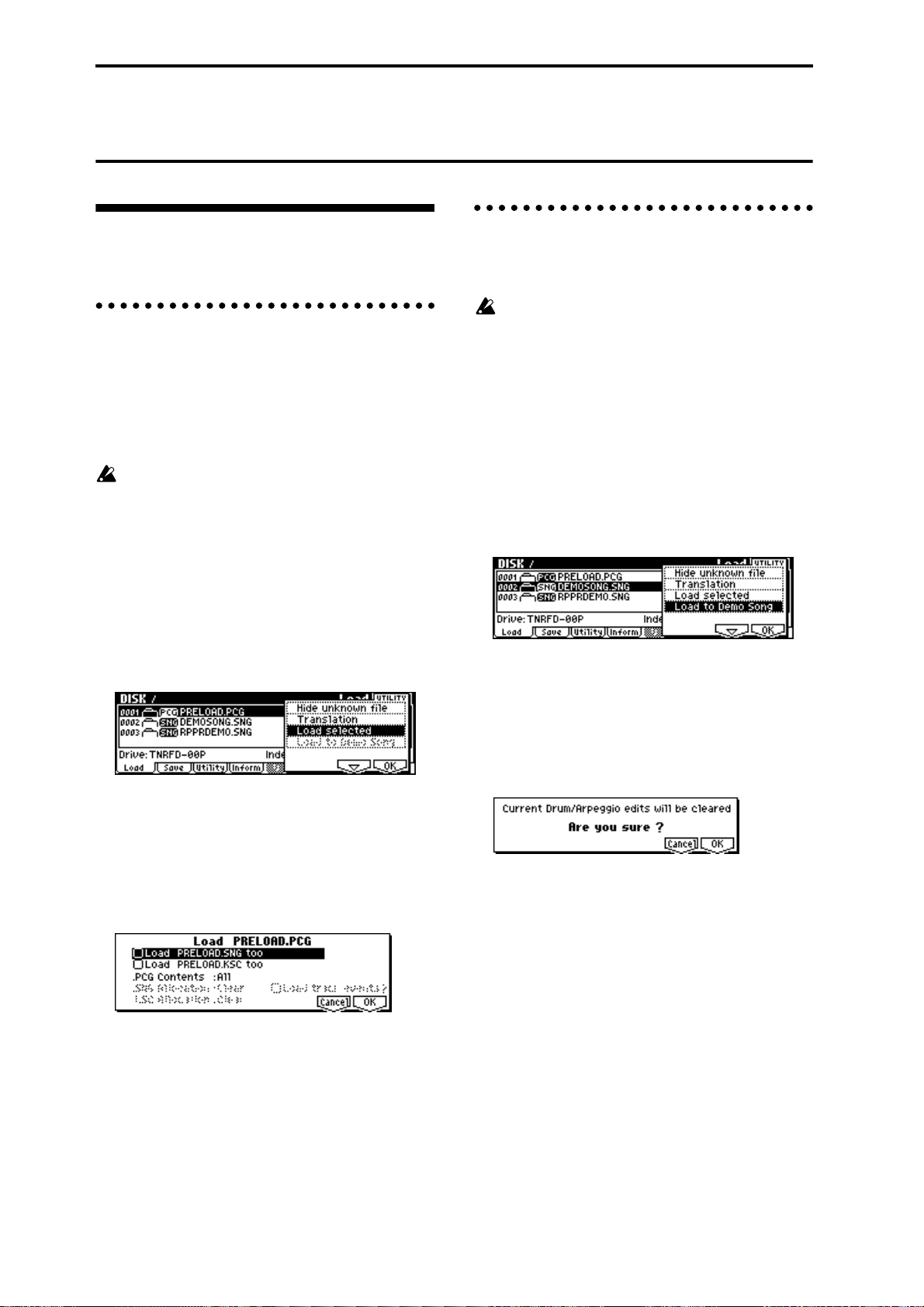
Restoring the factory settings
Loading the preloaded data and demo songs
1. Loading programs, combinations,
global settings, arpeggio patterns,
and drum kits
Here’s how to restore the preloaded data (☞p.36) for
programs, combinations, global settings, user arpeggio
patterns, and user drum kits to the factory settings.
When you perform the Load operation described
below, the data that had been previously written
will be overwritten (and lost).
1 Insert the included TNRFD-00P floppy disk into
the floppy disk drive.
For the contents of the included floppy disks, refer
to p.81. For details on handling and inserting floppy
disks, refer to p.84.
2 Press the [DISK] key to enter Disk mode.
3 Press the [F1] (“Load”) key.
File information will be displayed in the Load page.
4 Select “PRELOAD.PCG”
It will be highlighted.
A .PCG file contains programs, combinations, drum
kits, arpeggio patterns, and global setting data.
5 Press [F8] (“UTILITY”) key, and select Utility
“Load Selected.”
A dialog box will appear.
2. Loading the demo songs
Here’s how to restore the demo song data played in the
DEMO/SNG page to the factory settings.
When you load this data, the multi data in Multi
mode will be overwritten. Please save it before you
continue. Any editing you did on the drum kit or
arpeggio pattern data in the Global mode memory
area will also be lost. (
1 Insert the included TNRFD-00P floppy disk into
the floppy disk drive.
For the contents of the included floppy disks, refer
to p.81. For details on handling and inserting floppy
disks, refer to p.84.
2 Press the [DISK] key to enter Disk mode.
3 Press the [F1] (“Load”) key.
File information will be displayed in the Load page.
4 Select “DEMOSONG.SNG”
It will be highlighted.
The DEMOSONG.SNG file contains demo song
data.
5 Press the [F8] (“UTILITY”) key, and select the
“Load to Demo Song” utility.
The following dialog box will appear.
6 Press the [F8] (“OK”) key to begin loading.
☞PG p.132)
6 Set “.PCG Contents” to All. (☞p.81)
7 Press the [F8] (“OK”) key to begin loading.
42
Page 49

Program mode
In Program mode you can select and edit programs.
Program mode consists of pages 1.1: Play–7.3: Ed–MasterFX.
In 1.1: Play you can select and play programs. You can
also edit the sound in simple ways, and make arpeggiator settings. (☞p.26)
In 2.1: Ed–Basic–7.3: Ed–MasterFX, you can edit the
parameters of the program that was selected in 1.1:
Play.
The TRITON-Rack provides AUDIO INPUT jacks
that allow an external audio source to be input. In
addition to sampling the external audio input in
Sampling mode, you can apply the TRITONRack’s effect section to the external audio input in
other modes such as Program mode, or even use
vocoder effects that combine the sound of an oscillator with an external audio source (☞p.97, PG
p.197)
All transmission and reception of MIDI data in
Program mode is performed on the Global MIDI
channel. The global MIDI channel is set in GLOBAL 2.1: MIDI “MIDI Channel.”
Basic program editing
With the factory settings, the TRITON-Rack’s INT-A–
INT-D contain preloaded programs. You can modify
these programs, or create your own original programs
from an initialized state.
You can also create original programs using samples/
multisamples that you sampled in Sampling mode (or
loaded into memory in Disk mode).
Programs you edit or create can be written to 1,664 program memory locations: bank INT-A–INT-E, and EXBA–EXB-H. Programs can also be saved in Disk mode
on external media such as floppy disk. (☞p.36)
For parameters in 2.1: Ed–Basic–5.3: Ed–LFOs that
are set independently for each oscillator 1 and 2,
you can use the Utility “Copy Oscillator” to copy
settings from one oscillator to the other. This is a
convenient way to make the same settings for two
oscillators, or to copy settings from one oscillator
to the other.
If you wish to save an edited program into internal
memory, be sure to Write the program. (☞p.37)
Basic functions
How a program is organized
A program consists of the many parameters of 2.1: Ed–
Basic–7.3: Ed–MasterFX. The diagram below shows the
structure of a program.
Program Basic : 2.1-1
OSC1 LFO2 : 5
Amp1 Mod. : 5
.3-2
Amp1 Level/Pan : 5.1-1
.1-2
Amp1 EG : 5
.1-3
OSC Basic : 2.1-2, 4
OSC1 Pitch Mod. : 3.1-1/2
OSC1 LFO1 : 5
.3-1
Filter1 Mod. : 4.1-2,3
Filter1 LFO Mod. : 4.1-4
Filter1(A/B) : 4.1-1
Filter1 EG :
4.1-5
If the separately sold EXB-MOSS option is
installed, you will be able to use bank F. The
parameter structure of bank INT–F programs is
different than that of the other banks. Refer to the
EXB-MOSS owner’s manual.
In this section we will give examples of how to modify
representative parameters in each page. For details on
all parameters, refer to in the PG p.1–.
2.1-5
Controller Setup:
2.2
Arpeggiator : 6.1
AUDIO OUTPUT
L/MONO, R
AUDIO OUTPUT
INDIVIDUAL 1,2,3,4
BUS : 7.1-1
OSC1,2
Insert Effect
Master Effect
IndividualOutput
Insert Effect1 ... 5:
7.2
Master Effect 1, 2:
7.3-1...3
Audition:
MasterEQ : 7.3-4
Program mode
Pitch EG : 3.1-5
Oscillator / Pitch
Filter
Ampilfier
OSC 1
OSC 2
Effect
1.1-1 and 2.1-2 etc. indicate the page tab screens used when editing on the TRITON-Rack.
43
Page 50

The three elements of sound
Sound can be broken down into three elements: pitch,
tone, and volume.
On the TRITON-Rack, these elements correspond to
the Pitch, Filter, and Amplifier settings of the program.
In other words you would adjust the Pitch settings to
modify the pitch, the Filter settings to modify the tone,
and the Amplifier settings to modify the volume.
In Oscillator (Oscillator: 2.1: Ed-Basic settings) you
select the waveform multisample that determines the
basic sound, and specify its pitch. This sound is then
modified by the pitch settings (Pitch: 3.1: Ed-Pitch), fil-
ter settings (Filter: 4.1, 4.2: Ed-Filter), and amp settings
(Amplifier: 5.1, 5.2: Ed-Amp) to create the basic sound
of the program.
This basic sound can then be modified further by using
insert effects (7.2: Ed-Insert FX settings), master
effects, and master EQ (7.3: Ed-Master FX settings) to
apply finishing touches. When arpeggiator settings
(6.1: Ed-Arp) and controller settings (2.2: Ed-Ctrl) are
added to this, the final result is called a “program.”
Programs that are used in Combination mode or
Multi mode have insert effect, master effect, master
EQ, arpeggiator, and controller settings that are
separate from those of Program mode.
Basic (Prog Basic) page
Mode (Oscillator Mode)
This sets the mode of the oscillator.
Single uses one oscillator and Double uses two oscillators. In the case of Single the maximum polyphony is
60 notes, and in the case of Double the maximum
polyphony is 30 notes. If you wish to use a Drum Kit to
create a drums program, select Drums. (☞p.50)
Mode (Voice Assign Mode)
Selects whether the program will sound in Poly (poly-
phonically) or Mono (monophonically).
If this is set to Poly, you will be able to play chords
using the program. If this is set to Mono, only one note
will sound even if you play a chord. Normally you will
set this to Poly, but it is effective to use Mono when
you are playing sounds such as analog-synth bass or
synth lead. T ry switching between Poly and Mono, and
listen to the result.
OSC1 page, OSC2 page
The Compare function
When 2.1: Ed–Basic–7.3: Ed–MasterFX are displayed,
you can press the [COMPARE] to make the LED light.
This will recall the sound that had been written before
you started editing. Press the [COMPARE] key once
again and the LED will go dark, and you will return to
the sound that you had been editing. Use this function
when you wish to compare the unedited sound with
the results of your editing.
When the [COMPARE] key LED is lit, editing a
parameter will make the LED go dark, and that
sound will now be the sound that is recalled when
the [COMPARE] key LED is dark.
Oscillator settings 2.1: Ed–Basic
In 2.1: Ed–Basic you can make oscillator-related settings. The TRITON-Rack provides two oscillators, and
for each oscillator you can select a basic waveform
(“multisample”) and set the pitch. The multisamples
provided by the TRITON-Rack include waveforms for
musical instruments such as pianos, as well as special
waveforms unique to synthesizers. Multisamples
reproduce the complex overtone structure and frequency characteristics that allow us to identify a sound
as being “piano-like” or “guitar-like.”
Specifies the multisample for oscillator 1, 2.
Selecting a multisample
The multisample will determine the basic character of
the program.
● Use “High MS Bank” to select the multisample
bank, and use “High Multisample” to select the
multisample.
If the “High MS Bank” is ROM, you can select preset multisamples. “High Multisample” can be
selected from a range of 000–424. (
If the “High MS Bank” is RAM, you can select multisamples that were created in Sampling mode or
loaded in Disk mode. “High Multisample” can be
selected from a range of 000–999.
If “High MS Bank” is EXB*, you can select multisamples from a separately sold EXB-PCM series
option. The type of installed option will be shown in
“*.”
You can use the “Select by Category” utility to
select internal ROM multisamples from 15 categories. (
☞PG p.8)
High Multisample and Low Multisample
If you specify a High and Low multisample for an
oscillator, either the High or the Low multisample will
sound depending on the velocity of the note (i.e., the
strength at which you play the keyboard). This function is called velocity multisample switching.
☞VNL)
44
Page 51

1 Specify different multisamples for “High Multi-
sample” and “Low Multisample.”
2 Specify a velocity value for “Velocity SW L→H.”
Notes played on a connected MIDI keyboard at a
velocity less than the value you specify will sound
the Low multisample; velocities at or above this
velocity value will sound the High multisample.
For example if you set “Velocity SW L→H” to 100,
playing the keyboard softly will sound the “Low”
multisample, and playing strongly will sound the
“High” multisample.
3 Adjust the “Level” for High and Low multisam-
ples to set their volume balance.
If you do not wish to use this function, set the
“Velocity SW L → H” value to 001. Only the High
multisample will sound.
Rev (Reverse) check box
If this is checked, the multisample will be played backward. This can produce interesting results when used
on sound-effects, etc. Normally you will not check this.
When “Oscillator Mode” = Double
To use OSC2, set “Mode (Oscillator Mode)” to Double
in the Basic (Prog Basic) page.
In the same way as for OSC1, you can set High and
Low multisamples for OSC2.
The playback pitch can be set independently. By using
the same multisample with slightly different “Tune”
settings, you can “detune” the oscillators to produce a
richer sound.
It will be convenient to use the Utility “Copy Oscillator” to make the oscillator settings match each
other.
When “Oscillator Mode” = Drums
(It is easy to create programs using samples that
were recorded in Sampling mode, or multisamples/
samples that were loaded in Disk mode.)
• Nine internal drum kits (ROM)
• 143 user drum kits created in Global mode
(Drum samples or original samples you recorded
can be freely assigned to each key to create a drum
kit. For the sound of each key, you can make filter
and amp settings, and specify routing to the effects
and to the individual audio outputs.
• Expansion drum sets (if separately sold EXB-PCM
options are installed)
V.Zone (Velocity Zone) page
Here you can specify the range of velocities that will
sound oscillators 1 and 2. In the example shown above,
the velocity ranges are as follows.
• OSC1 will sound for all velocity values.
• OSC2 will sound only for strongly played notes (64
and above).
• You can use Velocity Multisample Switching in
addition to this (
Multisample”). For this example, set “OSC1” in
“Velocity SW L→H” to 32 and “OSC2” to 96. The
settings are shown as vertical lines in the velocity
zone display.
In this example, the multisamples will sound over
four levels.
Velocity values 001–031:
sound only the OSC1 Low multisample.
Velocity values 032–063:
sound only the OSC1 High multisample.
Velocity values 064–095:
sound the OSC1 High multisample and the OSC2
Low multisample.
Velocity values 096–127:
sound the OSC1 High multisample and the OSC2
High multisample.
☞“High Multisample, Low
Basic functions
Program mode
In the Basic (Prog Basic) page, set “Mode (Oscillator
Mode)” to Drums. When this is set to Drums, you will
be able to create a drum program.
This will select a drum kit instead of a multisample.
The TRITON-Rack provides sixteen factory preset
drum kits that are suitable for a wide variety of music.
(
☞Drumkit name, VNL)
Here you can only select a drum kit. To edit or create a
drum kit, use GLOBAL 5.1: DKit (☞p.78).
The following multisamples or drum kits can be used
for the oscillator.
• 425 internal multisamples (ROM)
• Expansion multisamples (if separately sold EXBPCM options are installed)
• Multisamples created in Sampling mode (RAM)
Controller settings 2.2: Ed–Ctrl
Ctrls (Controls) page
For each program, this tab lets you make settings for
the “SW1” and “SW2,” and for the B-mode of REALTIME CONTROLS knobs [1]–[4] (☞p.100, PG p.10, 213,
214)
Pitch settings 3.1: Ed–Pitch
Here you can specify how the pitch of the multisample
selected for the oscillator will change. Pitch EG and
LFO settings allow the pitch to varied over time.
The parameters of the OSC2 page and OSC2lfo page
are valid if “Mode (Oscillator Mode)” is set to Double.
45
Page 52

OSC1 page
Pitch
The “JS (+X)” and “JS(–X)” settings specify the amount
of pitch change (in semitones) that will occur when
MIDI pitch bend messages are received or when the
joystick etc. of a MIDI-connected TRITON or other
instrument is moved to left or right. A setting of +12
allows the pitch to be controlled a maximum of one
octave upward; a setting of –12 allows the pitch to be
controlled a maximum of one octave downward.
“Ribbon (#16)” specifies the amount of pitch change
(in semitones) that will occur when MIDI control
change (CC) #16 messages are received or when the
ribbon controller of a TRITON or other MIDI-connected instrument is moved to left or right. With a setting of +12, the pitch will rise one octave at the far right
of the ribbon controller, and fall one octave downward
at the far left of the ribbon controller.
Pitch EG
When the “Intensity” value is set to +12.00, the pitch
EG specified in the Pitch EG page will produce a maximum of ±1 octave of pitch change.
Portamento
If “Enable” is checked, portamento will be applied.
Portamento makes the pitch change smoothly when
you play the next note before releasing the previous
note.
The “Time” parameter specifies the portamento time.
As this value is increased, the pitch will change over a
longer time. With a value of 000, there will be no porta-
mento.
If Porta.SW (CC#65) is assigned as the function of
“SW1” or “SW2,” the portamento effect can be
switched on/off by “SW1” or “SW2.”
OS1lfo (OSC1 LFO) page
“Intensity (AMS Intensity)” specifies the depth of
vibrato that will be applied by the LFO when AMS
(Alternate Modulation Source) is operated. For example if “AMS (LFO1 AMS)” is set to AfterT and you set
an appropriate value for “Intensity (AMS Intensity),”
vibrato will be applied when you apply pressure to the
keyboard of a connected MIDI instrument or when
MIDI aftertouch messages are received.
EG (Pitch EG) page
Here you can make settings for the pitch EG.
When you wish to create sound effects etc., set the
pitch EG to make major changes in pitch over time.
To realistically simulate the slight change in pitch that
occurs when a string is plucked or at the attack of a
brass or vocal sound, you can use the EG to create a
subtle change in pitch at the attack (
EG and LFO
By using an EG (envelope generator) to apply timevarying change or by using an LFO (Low Frequency
Oscillator) to apply cyclic change to pitch, filter, or
amp, you can create changes in the pitch, tone, and volume.
EG (Envelope Generator)
The TRITON-Rack provides a Pitch EG, Filter EG, and
Amplifier EG, which produce time-varying changes in
pitch, tone, and volume respectively.
note-on
Level
Attack Level
Decay Time
Attack Time
Start Level
LFO (Low Frequency Oscillator)
For each oscillator, the TRITON-Rack provides two
LFO’s that can be used to apply cyclical change in
pitch, tone, and volume.
Examples of this are vibrato (cyclical change in pitch),
wah (cyclical change in tone), and tremolo or auto-pan
(cyclical change in volume).
Break Level
Sustain Level
Slope Time
☞PG p.12).
note-off
Release Level
Release Time
Time
LFO 1/2
An LFO can be used to cyclically modulate the pitch
(the “vibrato” effect).
“Intensity (LFO Intensity)” sets the depth to which the
LFO specified in 5.3: Ed-LFOs will affect the pitch. With
a setting of +12.00, vibrato will produce a maximum of
±1 octave of pitch change.
“JS+Y Int.” specifies the depth of vibrato that will be
applied by the LFO when a joystick etc. is operated on
a MIDI-connected TRITON or other instrument, or
when CC#1 is received.
46
Filter settings
4.1: Ed–Filter1, 4.2: Ed–Filter2
The filter allows you to diminish or emphasize specified frequency areas of the multisample selected for the
oscillator. The tone of the sound will depend signifi-
cantly on the filter settings.
Page 53

The TRITON-Rack provides Filter 1 for OSC1 and Filter 2 for OSC2. For each of these filters, you can select
from two types (Low Pass Resonance or Low Pass &
High Pass). Filter 2 can be used if “Mode (Oscillator
Mode)” is set to Double.
Level
Overtones included
in the original multisample
Frequency (pitch)
Filter
Level
Filter characteristics
This area of
overtones will
be diminished
Overtones after
passing through
the filter
Frequency (pitch)
Resonance
When “Resonance” is set to a higher value, the overtones in the region of the cutoff frequency will be
boosted as shown in the diagram below, giving a distinctive character to the sound.
When resonance is applied
Low Pass
Level
Basic page
Filter Type, Filter A, Filter B
Selects the type of filter, and specify the “Frequency”
(cutoff frequency) and “Resonance” (resonance level).
• Low Pass Resonance (24 dB/oct low pass filter
with resonance): Make settings for filter A.
• Low Pass & High Pass (12 dB/oct low pass filter
and 12 dB/oct high pass filter in series connection):
Make low pass filter settings in filter A, and high
pass filter settings in filter B.
Low pass filter
This is the most common type of filter, which passes
the low frequency range and cuts the high frequency
range. When the overtones of the high range are cut, a
bright sound will become darker (more mellow).
24 dB/oct and 12 dB/oct refer to the steepness of the
cut. 24 dB/oct means that the gain will decrease 24 dB
in one octave (i.e., as the frequency doubles). A 12 dB/
oct filter would decrease the gain 12 dB in one octave.
The 24 dB/oct filter produces a steeper cut.
Low Pass
Level
12dB/oct
24dB/oct
Frequency
Low resonance value High resonance value
Mod.1, Mod.2 page
Controllers and the filter EG can be used to modulate
the filter cutoff frequency that was specified in the
Basic page. By using a controller to vary the tone or by
using an EG to create time-varying changes, you can
add a rich variety of tonal change to the sound.
Keyboard Track (Mod.1 page)
The cutoff frequency can be adjusted by the position at
which a note is played on a connected MIDI keyboard.
• When Ramp “Low” is set to a positive (+) value,
the cutoff frequency will rise as you play lower on
the keyboard, making the sound brighter. When set
to a negative (–) value, the cutoff frequency will
fall as you play lower on the keyboard, making the
sound darker.
• When Ramp “High” is set to a positive (+) value,
the cutoff frequency will rise as you play higher on
the keyboard, making the sound brighter. When set
to a negative (–) value, the cutoff frequency will
fall as you play higher on the keyboard, making
the sound darker.
• Int. “to A” and “to B” adjust the effect that
keyboard tracking will have on filters A and B
(
☞PG p.15).
Basic functions
Program mode
High pass filter
This type of filter passes the high frequency range and
cuts the low frequency range. Use this when you wish
to make the sound thinner. However if the cutoff frequency (Frequency) is raised excessively high, the volume will become very low.
High Pass
Level
12dB/oct
Frequency
Filter EG (Mod.1 page)
Adjusts the effect produced by the filter EG, whose settings are made in the EG page.
• Use the Int. “to A” and “to B” settings to specify
the depth of the filter EG.
• Use the Vel “to A” and “to B” settings to specify
the effect of velocity on the filter EG.
•“AMS” and “Int to A, B” adjust the effect that
AMS will have on the filter EG depth.
These three settings will determine the depth of the
tonal change produced by the filter EG.
Filter Modulation (Mod.2 page)
Set this when you wish to produce tonal change by
using controllers etc. to vary the cutoff frequency.
47
Page 54

lfoMod (LFO Mod.) page
Indicates settings that allow the LFO to produce cyclic
changes in tone (a “wah” effect).
Intensity: “to A (LFO1 Int. to A)” and “to B (LFO1 Int.
to B)” specify how greatly the LFO will change the
tone.
JS-Y Int.: “to A” and “to B” specify the depth of the
wah effect that will be produced by the LFO when the
joystick of a MIDI-connected TRITON or other instrument is moved toward yourself, or when CC#2 is
received.
“Int. to A” and “Int. to B” specify the depth of the wah
effect that will be produced by the LFO when “AMS”
(Alternate Modulation Source) is operated. For example if “AMS” is set to AfterT, applying pressure to the
keyboard of a connected MIDI instrument (that has
aftertouch) will apply a wah effect.
EG page
Indicates settings for the filter EG, which controls timevariant changes in tone (
the EG here, and set the depth of its effect in the Mod.1
page “Filter EG” parameter.
Filter EG and Amplifier EG
When the Filter EG changes the cutoff frequency, the
tone will change. However depending on the volume
changes produced by the Amplifier EG, this can be
heard in different ways. For example by changing the
speed at which the tone and volume begin (attack) or
decay, you can significantly vary the character of the
tonal change. It is a good idea to adjust the changes of
both the Filter EG (tone) and the Amplifier EG (volume) as you proceed with editing. (
EG page, 5.2: Ed–Amp2, EG page)
☞PG p.17). Make settings for
☞“5.1: Ed–Amp1,
Volume
Piano
Volume decays gradually
Volume
Time
Organ
Volume remains constant
until note is released
Time
Lvl/Pan (Level/Pan) page
Amp1 Level, Amp2 Level
Adjusts the volume of the sound that has passed
through the oscillator, filter, and amp.
Pan
Specifies the pan (stereo position) after the signal has
passed through the oscillator , filter, and amp. Normally
you will set this to C064. If “Mode (Oscillator Mode)”
is Double and you wish to create a sense of stereo, set
the 5.1: Ed-Amp1 and 5.2: Ed-Amp2 parameter “Pan”
to left and right for oscillators 1 and 2 respectively.
With a setting of Random, the pan will change ran-
domly each time you play a note on a connected MIDI
keyboard, producing an interesting effect.
AMS Intensity
“Intensity” specifies the depth of the panning effect
that will occur when “AMS” is operated.
If you set “AMS” to Note No., the pan will change
according to the keyboard position at which you play a
note on a connected MIDI keyboard. With a setting of
LFO1 or 2, the pan will sweep from side to side (auto
pan). Other settings allow you to move the oscillator
pan by operating a controller.
Amplifier settings
5.1: Ed–Amp1, 5.2: Ed–Amp2
These settings affect the volume. Here you can adjust
the way in which the Amp EG and LFO produce timevarying and cyclic changes in volume, and how the
controllers etc. will affect the volume.
Amp1 applies to OSC1, and Amp2 applies to OSC2.
Amp2 can be used if “Mode (Oscillator Mode)” is set to
Double.
For example, the volume of a piano note begins at a
high volume the instant you play the note, and then
decreases gradually. The volume of an organ note
remains constant as long as you continue pressing the
key. The volume of a note on a violin or wind instrument can be varied during the note by the musician
(i.e., by regulating the amount of pressure on the bow
or the force of the breath).
48
Use DKit Setting
This is valid when “Mode (Oscillator Mode)” is set to
Drums. If this is checked, the pan location specified by
the Drum Kit for each drum sound will be used. If this
is unchecked, all drum sounds will sound at the same
location. Preload and GM drum kits are set to stereo
settings. Normally you will leave this checked.
Mod. page
Keyboard Track
This varies the volume according to the keyboard position at which you play a note on a connected MIDI keyboard.
• When Ramp “Low” has a positive (+) value, the
volume will increase as you play lower on the
Page 55

keyboard. With a negative (–) value, the volume
will decrease as you play lower on the keyboard.
• When Ramp “High” has a positive (+) value, the
volume will increase as you play higher on the
keyboard. With a negative (–) value, the volume
will decrease as you play higher on the keyboard.
Amp Mod.
“Velocity Int” is used by most programs to decrease
the volume of softly played notes and increase the volume of strongly played notes, and this Amp Modulation parameter adjusts the depth of this control.
Normally you will set Amp Modulation to positive (+)
values. As this setting is increased, ther e will be greater
volume difference between softly played and strongly
played notes.
LFO1 Mod., LFO2 Mod.
Specify how the LFO’s will produce cyclic changes in
volume (the tremolo effect).
The volume will be affected by the LFO(s) for which
you set an “Intensity (LFO1 Intensity, LFO2 Intensity)”
value.
“Int (AMS Intensity)” adjusts the depth by which the
tremolo effect produced by the LFO will be affected
when you operate an “AMS (LFO1 AMS, LFO2 AMS).”
For example if you set “AMS” to JS-Y #02 , tremolo will
be applied when you move the joystick of a MIDI-connected TRITON etc. toward yourself, or when CC#02 is
received.
EG page
Here you can make settings for the amp EG, which
changes the volume over time.
Every instrument has its own characteristic curve of
volume change. This is part of what gives each instrument its identifiable character . Conversely, by applying
a strings-type Amp EG curve to an organ-type multisample, you can produce a sound with a character
unlike a typical organ.
Piano
Filter1, 4.2: Ed-Filter2, 5.1: Ed-Amp1, and 5.2: EdAmp2 pages.
OSC1 LFO1, OSC1 LFO2, OSC2 LFO1, OSC2 LFO2
“Waveform” selects the type of LFO. You can choose
from a variety of waveforms, including standard waveforms such as Triangle, Saw, Square, and Sine, as well
as Step or Random PG waveforms that pr oduce a sample-and-hold effect (
Y ou can cr eate a wide variety of effects by adjusting the
“Ofs,” “Fade,” and “Dly” settings, and by changing
the sign (+/-) of the “Intensity” setting in the 3.1: EdPitch, 4.1: Ed-Filter1, 4.2: Ed-Filter2, 5.1: Ed-Amp1, and
5.2: Ed-Amp2 pages. “Frequency” specifies the speed
of the LFO.
☞PG p.23).
Freq.Mod (Frequency Modulation)
“AMS” can be used to vary the LFO speed. This lets
you change the LFO speed by operating a controller , or
by the EG or Keyboard Track settings.
MIDI/Tempo Sync.
If “MIDI/Tempo Sync” is checked, the “Frequency”
setting will be ignored, and the LFO will synchronize
to the tempo of the arpeggiator etc. This lets you produce vibrato, wah, auto-pan, or tremolo that is synchronized to the playback speed of the arpeggiator.
Arpeggiator settings 6.1: Ed–Arp.
Here you can make arpeggiator settings (☞p.85).
BUS settings 7.1: Ed–BUS
Basic functions
Program mode
Organ
Strings
LFO settings 5.3: Ed–LFOs
For each oscillator, you can use two LFO (Low Frequency Oscillator) units: LFO1 and LFO2. You are free
to select the type of each LFO and set its speed.
The depth of the LFO1 and LFO2 that you specify here
is adjusted by the settings of the 3.1: Ed-Pitch, 4.1: Ed-
Y ou can specify the oscillator r outing (the signal sent to
the insert effects, master effects, and independent outputs) (☞p.95).
Insert Effect settings 7.2: Ed–InsertFX
Here you can select insert effects and make settings for
them (☞p.95).
Master Effect settings
7.3: Ed–MasterFX
Here you can select master effects and make settings
for them. The master EQ is also set here (☞p.96).
49
Page 56

More about Alternate Modulation
Alternate Modulation is a type of modulation that can
be used to control various aspects of the sound.
AMS (Alternate Modulation Source) refers to any of
the numerous sources that can control alternate modulation, and includes controllers such as the realtime
controller that you physically operate, incoming MIDI
data, as well as modulators such as the EG or LFO.
Since the TRITON-Rack allows you apply modulation
to a modulator, this type of control is referred to as
“alternate modulation.”
Intensity is a parameter that sets the degree (speed or
depth) to which AMS will control alternate modulation.
Combinations of modulations that are frequently used
in on the TRITON etc. performance (such as using the
joystick or ribbon controller to vary the pitch) are also
provided as special parameters separately from alternate modulation.
The TRITON-Rack provides 29 types of alternate modulation.
In single mode you can use 29 alternate modulation
destinations of 29 types, and in double mode you can
use 55 alternate modulation destinations of 29 types.
There are 42 AMS sour ces. (However depending on the
type of modulation, some sources cannot be selected.)
For details on alternate modulation and AMS, refer to
PG p.205.
Suggestions on using alternate modulation
When making settings for alternate modulation, think
of the effect that you wish to produce, what type of
modulation will be necessary to produce that effect,
and what parameter of the oscillator , filter, or amplifier
needs to be controlled. Then select a source (“AMS”)
and set the “Intensity.” If you proceed logically in this
way, you will achieve the desired effect.
For example if you want to “control a guitar-like sound
so that it appears to be approaching feedback when the
joystick is moved away,” you will make settings so that
the joystick controls filter modulation or the resonance
level.
50
Page 57

Combination mode
In Combination mode you select and play combinations and edit them.
Combination mode consists of pages 1.1: Play–7.3: Ed–
MasterFX.
In 1.1: Play you can select and play combinations. You
can also do some overall editing, and make arpeggiator
settings (☞p.27).
In 2.1: Ed–Basic–7.3: Ed–MasterFX you can edit the
parameters of the combination that was selected in 1.1:
Play.
How a combination is organized
A combination consists of a variety of parameters that
can be accessed in 2.1: Ed–Basic–7.3: Ed–MasterFX. The
diagram below shows how a combination is structured.
Basic combination editing
Banks INT-A–INT-D of the TRITON-Rack contain a
wide variety of combinations that use the preloaded
programs (bank INT-A and INT-B) and the preset and
preloaded user arpeggio patterns and effects. You can
edit these combinations, or create your own original
combinations from an initialized state.
Programs using sample waveforms/multisamples that
you sampled in Sampling mode (or loaded into memory in Disk mode) can also be used in a combination.
A combination that you edited or created can be written into one of 1,664 combination memory locations in
banks INT-A–INT-E or EXB-A–EXB-H. Combinations
can also be stored or organized on external media such
as floppy disk in Disk mode. (☞p.36)
If a program being edited in Program mode is used
in a combination, it will sound according to the settings being edited.
If you wish to save an edited combination in internal memory, you must write it. (☞p.37)
If the separately sold EXB-MOSS option is
installed, bank INT-F programs can be used for the
timbres of a combination. For details on the parameters of bank INT-F programs, refer to the EXBMOSS owner’s manual and PG p.251.
Suggestions for editing procedure
The parameters of each timbre are set in 2.1: Ed-Prog/
Mix–4.4: MIDI Filter4. This is where you create the
basic combination consisting of the programs you
select here.
First use 2.1: Ed-Prog/Mix to select the program for
each timbre, and then use 3.3: Ed-Key Zone and 3.4:
Ed-Vel Zone to specify the range in which each program will sound (layer, split, velocity switch, etc.).
Then adjust the volume of each timbre, and set various
other parameters.
To add finishing touches to the sound, you can make
insert effect settings (in 7.2: Ed-Insert FX) and master
effect and master EQ settings (in 7.3: Ed-Master FX)
that are separate from the effect settings of Program
mode. In addition, you can make arpeggiator settings
(in 6.1: Ed-Arp.) and controller settings (in 2.2: Ed-Ctrl)
to create the finished combination.
By using the “Solo Selected Timbre” utility, you
can listen only to the selected timbre. This is a convenient way to audition individual sounds of timbres that are layered. (☞p.28)
In pages that display all timbres 1–8, such as 2.1:
Ed-Prog/Mix, you can use the [ ], [ ] keys to
select timbres. You can also select timbres directly
by holding down the [TIMBRE/TRACK] key and
pressing one of the [F1
1/9]–[F8 8/16] keys.
Basic functions
Combination mode
Timbre1
Program
Timbre2
Program
Timbre3
Program
Timbre4
Program
Timbre8
Program
Parameters
Parameters
Parameters
Parameters
Parameters
BUS : 7.1-1
Timbre
Insert Effect
Master Effect
IndividualOutputs
Insert Effect 1...5
: 7.2
Controller Setup : 2.2
Arpeggiator : 6.1
Master Effect 1, 2
: 7.3-1...3
MasterEQ : 7.3-4
7.1-1 or 7.2 etc. indicate pages or tab screens used on the TRITON-Rack for editing.
AUDIO OUTPUT
L/MONO, R
AUDIO OUTPUT
INDIVIDUAL 1,2,3,4
51
Page 58
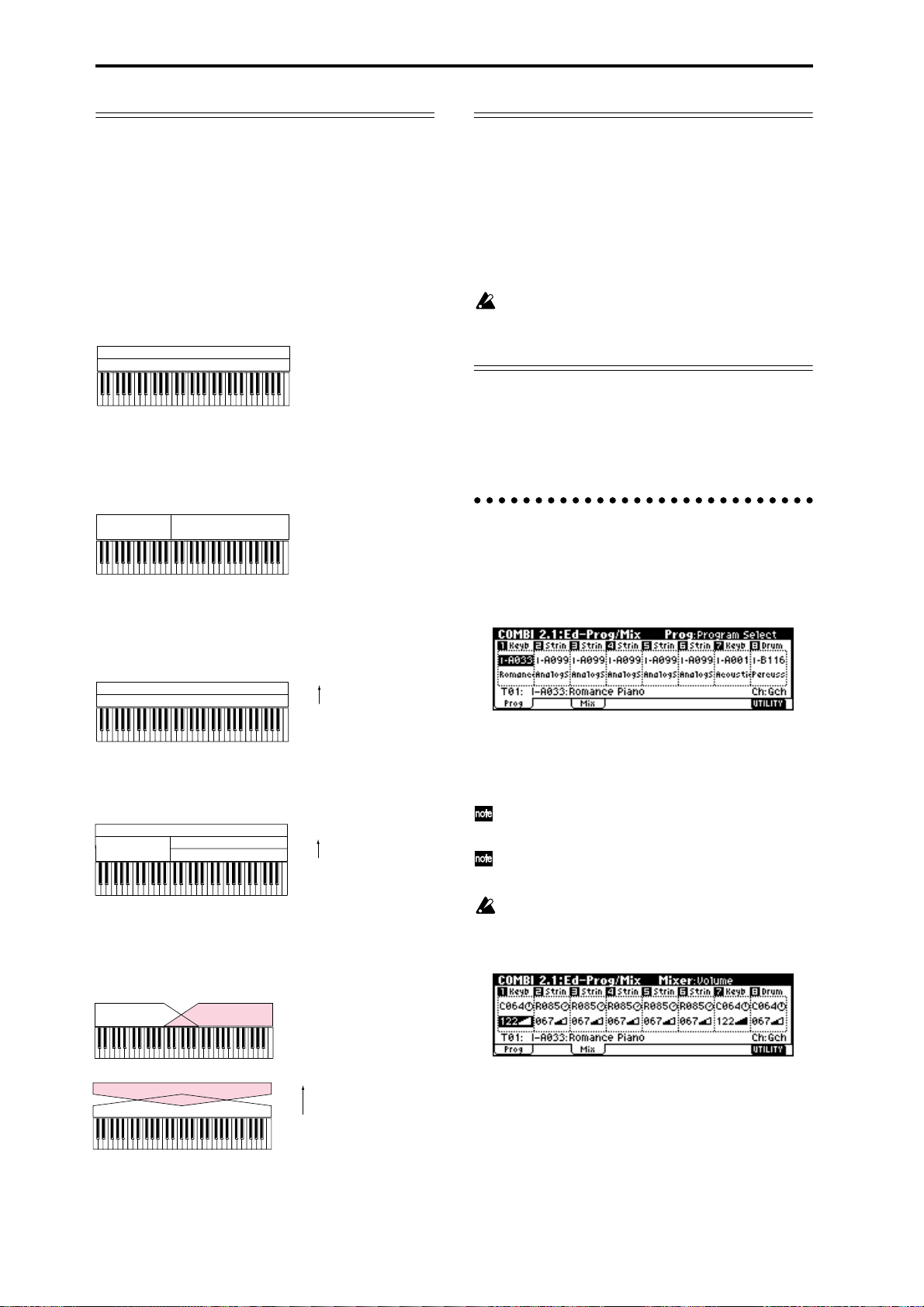
Layer, split, and velocity switch
Within a combination, you can use keyboard location
and velocity to change the program that sounds. The
programs assigned to each timbre can sound in three
ways: as a layer, a split, or a velocity switch. A combi-
nation can be set to use any one of these methods, or to
use two or more of these methods.
Layer
A setting that causes two or more programs to sound
simultaneously when you play a note on a connected
keyboard is called a Layer.
Program A
Program B
Layer:
Two or more programs sound
simultaneously.
Split
A setting that causes different programs to sound
when you play in different areas of a connected keyboard is called a Split.
Program A
Program B
Split:
Different programs will sound in
different areas of the keyboard.
Velocity switch (Velocity SW)
Velocity Switch (Velocity SW) refers to settings which
cause different programs to sound depending on the
velocity (keyboard playing dynamics).
Program B
Program A
In Combination mode, you can use a different program
for each of up to eight timbres, and combine two or
more of the above methods to create even more complex setups.
Program A
Program B
Program D
Program C
As an additional possibility, you can set the slope for a
key zone or velocity zone so that the volume diminishes gradually. This lets you change a split into a key-
board crossfade, or a velocity switch into a velocity
crossfade.
Program A
Program B
Strong
Keyboard playing dynamics
Soft
Velocity Switch:
Keyboard playing dynamics
(velocity) switches between
different programs.
Strong
Keyboard playing dynamics
Soft
Example:
B and C, D are split. In the lower
keyboard range, A and B are
layered. In the higher keyboard
range, C and D are switched by
velocity and layered with A.
Keyboard X-Fade (keyboard crossfade):
As you play from low notes to high notes,
the volume of A will fade out, and the
volume of B will fade in.
The Compare function
When 2.1: Ed–Basic–7.3: Ed–MasterFX are displayed,
you can press the [COMPARE] key to make the LED
light. This will recall the combination that had been
written before you began editing. When you press the
[COMPARE] key once again the LED will go dark, and
you will return to the sound that you had been editing.
Use this when you wish to compare the edited sound
with the un-edited sound.
If you continue editing when the [COMPARE] key
LED is lit, the LED will go dark, and the current
sound will now be the sound that is recalled when
the [COMPARE] key LED is dark.
In the section below, we will edit typical parameters in
each page while listening to the effect of each parameter.
For a more detailed explanation of these parameters,
refer to PG p.31–.
Timbre 1–8 program, pan and volume
2.1: Ed–Prog/Mix
Here you can assign programs to each timbre 1–8, and
set pan and volume for each. (These settings can also
be made in the Prog and Mix pages of 1.1: Play.)
Prog page
Program Select
Assigns a program to each timbre.
You can use the “Select by Category” utility to
select programs from 16 categories. (☞p.28)
You can also use the [BANK] and [A]–[H] keys to
select the bank of the program.
If you wish to select programs by receiving MIDI
program changes, do so in P1.1: Play.
Mix (Mixer) page
52
Program B
Program A
Strong
Keyboard playing dynamics
Soft
Velocity X-Fade (velocity crossfade):
As you play with increasingly stronger
velocity, the volume of A will fade out, and
the volume of B will fade in.
Pan
Specifies the panning (stereo location) for each timbre.
A setting of C064 will reproduce the oscillator pan set-
ting of the program. Moving this to left or right will
move the sound to left or right while preserving the
pan relationship between the oscillators. A setting of
L000 is far left, and R127 is far right. (
☞PG p.34)
Page 59
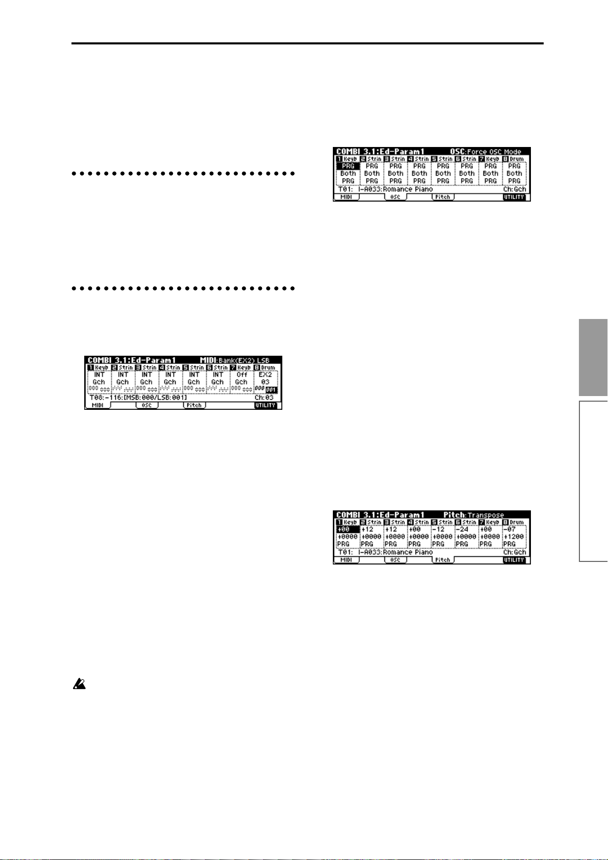
Volume
Adjusts the volume of each timbre.
Create the overall sound by adjusting the volume balance between timbres. The “Volume” setting is an
important aspect of creating the sound, and this setting
will have a significant effect on the overall impression
produced by the combination.
Controller settings 2.2: Ed–Ctrl
Bank(EX2) MSB, Bank(EX2) LSB
This setting is valid when “Status” is set to EX2. It specifies the Bank Select message that will be transmitted
from the TRITON-Rack.
OSC page
Ctrls (Controls) page
For each combination, you can specify the functions of
the B-mode functions of REALTIME CONTROLS
knobs [1]–[4], and the “SW1” and “SW2.” (☞p.100, PG
p.36, 213, 214)
Settings for status, MIDI channel, and
playing mode 3.1: Ed–Param1
MIDI page
Status
Here you can specify the state of MIDI and the internal
tone generator for each timbre. Normally when sounding the internal tone generator of the TRITON-Rack,
you will set this to INT. Set this to Off for timbres that
you are not using. With settings of Off, EXT, or EX2,
the TRITON-Rack will not sound. With settings of EXT
or EX2, you can control an external tone generator connected via MIDI. (
☞PG p.36)
Force OSC Mode
Normally you will set this to PRG.
If you wish to force a polyphonic program to sound
monophonically, set this either to Mono or LGT
(Legato). Conversely, set this to Poly if you wish to
force a monophonic program to play polyphonically
(
☞PG p.37).
OSC Select
Normally you will set this to Both.
If the timbre is using a program whose “Mode (Oscillator Mode)” is Double, and you want only OSC1 or
OSC2 (not both) to sound, set this to OSC1 (only OSC1
will sound) or OSC2 (only OSC2 will sound).
Portamento
Normally you will set this to PRG.
If you want the portamento setting specified for the
program of the timbre to be forced off, set this parameter to Off. Conversely, if you want to forcibly turn the
portamento on, or to change the portamento time, set
this to a value of 001–127 to specify the portamento
time.
Pitch page
Basic functions
Combination mode
MIDI Channel
Sets the MIDI channel of the timbres that you wish to
sound to match the MIDI channel of the transmitting
device. When note data is received on a matching channel, the corresponding channel of the TRITON-Rack
will sound (if “Status” is set to INT).
Normally, you will set the MIDI channel of the transmitting device to match the global MIDI channel of the
TRITON-Rack, and set this “MIDI Channel” parameter
to Gch. If this parameter is set to Gch, the MIDI channel of the timbre(s) will always match the global MIDI
channel even if you change the global MIDI channel.
On some preloaded combinations that use the arpeggiator , timbres assigned to the arpeggiator may not
have a “Status” of INT and “MIDI Ch” of Gch.
The reason for this is that these settings are for timbres that sound only when the arpeggiator is on.
This is a very useful technique for creating combinations that use the arpeggiator. Refer to “Arpeggiator settings in Combination and Multi modes”
(☞p.87, PG p.43), and study the relationship
between arpeggiator assignments, “Status,” and
“MIDI Channel.”
Transpose, Detune (BPM Adj.)
These parameters adjust the pitch of the timbre.
• In a layer-type combination, you can set two or
more timbres to the same program, and create a
richer sound by using “Transpose” to shift their
pitch apart by an octave or by using “Detune” to
create a slight difference in pitch between the two.
• In split-type combinations, you can use
“Transpose” to shift the pitch (in semitone units) of
the programs specified for each key zone.
• If you wish to change the playback pitch of a drum
program, use “Detune.” If you change the
“Transpose” setting, the correspondence between
notes and drum sounds will change.
53
Page 60

Adjusting the BPM of multisamples or samples created in Sampling mode
If a timbre program uses multisamples or samples that
you created in Sampling mode (or loaded in Disk
mode) to a specific BPM value, you can use the
“Detune BPM Adj.” utility with a specified BPM
value. This changes the BPM by changing the playback
pitch. (
☞PG p.38)
Note timing and scale settings
3.2: Ed–Param2
Other page
Delay [ms]
Specifies the timing at which the program of each timbre will sound.
Select the preload combination INT–A127: One Fin-
gerTVShow, and play a single note on a connected
MIDI instrument. Timbres will sound consecutively,
according to their Delay setting. If you select KeyOff
for this parameter , the timbre will sound when the note
is released.
Use Prog’s Scale, Combi’s Scale
Specifies the scale for each timbre. If you check “Use
Prog’s Scale,” the scale specified by the program will
be used. Timbres for which this is not checked will use
the “Combi’s Scale” setting.
Layer and split settings
3.3: Ed–Key Zone
Indicates settings such as layer, split, and keyboard
crossfade.
Timbres 2 and 3 create a layer. Timbre 1 and timbres 2/
3 are split between the B3 and C4 note numbers.
Timbre 3
Timbre 2
As an example here, we will explain how to create a
combination like the one shown above.
1 In 1.1: Play or 2.1: Ed-Prog/Mix, select the pro-
grams that timbres 1–3 will use.
Select a piano program for timbre 1.
Select a brass program for timbre 2.
Select a strings program for timbre 3.
2 In the MIDI page of 3.1: Ed-Param1, set “Status” to
INT for all the timbres that you wish to use, and
set “MIDI Channel” to either Gch or to match the
global MIDI channel (a “G” will be displayed
after the channel number).
3 In the Key page of 3.3: Edit-Key Zone, set “Top
Key” and “Bottom Key.”
Set timbre 1 to a “Top Key” of G9 and a “Bottom
Key” of C4.
Set timbres 2 and 3 to a “Top Key” of B3 and a “Bottom Key” of C–1.
Y ou can also enter these values by holding down the
[ENTER] key and playing a note on a connected
MIDI instrument.
Strings
Brass
PianoTimbre 1
C–1 C4 G9B3
Slope page
Here you can specify the range of keys over which the
original volume will be reached, starting at the top key
and bottom key.
In the case of the above example, you could set the key
zones so that a portion of timbres 1 and 2 overlaps (i.e.,
is layered) with timbre 3, and set “Top Slope” and
“Bottom Slope” so that the sound changes gradually,
instead of changing suddenly between B3 and C4.
Velocity switch settings
3.4: Ed–Vel Zone
Key page
Specifies the range of notes that will sound each timbre.
Each area that sounds a timbre is referred to as a Key
Zone. By setting key zones, you can create a combination in which different programs sound in different
areas of the keyboard.
By combining key zones specified for each timbre, you
can create layered or split combinations.
The upper and lower limits for the key zone of each
timbre are set by the “Top Key” and “Bottom Key”
respectively.
For example in the following diagram, timbres 1–3 are
set to create a layered and split combination. This is
specified by the key zone settings.
54
Here you can make settings for velocity switching and
velocity crossfading.
Vel (Velocity) page
For each timbre, you can specify a range of velocities
for which it will sound. The range of velocities for
which a timbre will sound is called the Velocity Zone.
By setting a velocity zone, you can set up a timbre
which will be sounded only by notes played at a certain strength, and not by stronger or weaker notes.
By combining timbres that have differing velocity zone
settings, you can create velocity switched combina-
tions.
The upper and lower limits of the velocity zone of each
timbre are determined by the “T op Velocity” and “Bot-
tom Velocity” respectively. The following diagram
Page 61

shows an example of a velocity switched combination
in velocity will switch between timbres 1 and 2 to play
different programs. Such combinations are created by
setting the velocity zone.
Timbre 1
Timbre 2
As an example, we will explain how to create a combination like the one shown above.
1 In 1.1: Play or 2.1: Ed-Prog/Mix, select the pro-
grams that timbres 1–2 will use.
Select a brass program for timbre 1.
Select a strings program for timbre 2.
2 In the MIDI page of 3.1: Ed-Param1, set “Status” to
INT for all the timbres that you wish to use, and
set “MIDI Channel” to either Gch or to match the
global MIDI channel (a “G” will be displayed
after the channel number).
3 In 3.4: Ed–Vel Zone Vel page, set the “Top Veloc-
ity” and “Bottom Velocity.”
Set timbre 1 to a “Top Velocity” of 127 and a “Bottom Velocity” of 64.
Set timbre 2 to a “Top Velocity” of 63 and a “Bottom
Velocity” of 1.
Y ou can also enter these values by holding down the
[ENTER] key and playing a note on a connected
MIDI instrument.
Brass
Strings
127
64
Velocity
63
switch
1
Slope page
Here you can specify the range of values over which
the original volume will be reached, starting from the
top velocity and bottom velocity.
In the case of the above example, you could set the
velocity zones of the two timbres so that they partially
overlap, and set “Top Slope” and “Bottom Slope” so
that the sound changes gradually, instead of changing
suddenly between velocity values of 63 and 64.
For example if you selected a bass program for timbre 1
and a piano program for timbre 2 to create a split-type
combination, you could make the following settings so
that pressing the damper pedal of a connected MIDI
keyboard would apply the damper effect only to the
piano program of timbre 2.
● Set “Damper CC#64” in 4.1: Ed-MIDI Filter1,
MIDI 1-2 page.
Timbre 1 “Damper CC#64”: unchecked
Timbre 2 “Damper CC#64”: checked
Arpeggiator settings
6.1: Ed–Arp.
Indicates settings for the arpeggiator (☞p.87).
Bus settings
7.1: Ed–BUS
Specifies the routing for each timbre (i.e., how it is sent
to the insert effects, master effects, and individual outputs). (☞p.96)
Basic functions
Insert Effect settings
7.2: Ed–InsertFX
Selects insert effects, and make settings for them.
(☞p.95, p.97).
Master Effect settings
7.3: Ed–MasterFX
Combination mode
Selects master effects, and make settings for them. Here
you can also make master EQ settings (☞p.96, p.97).
MIDI filter settings
4.1: Ed–MIDI Filter1–4.4: Ed–MIDI Filter4
For each MIDI Filter item, you can specify whether or
not the corresponding MIDI message will be transmitted and received. The checked items will be transmit-
ted and received.
The MIDI Filter settings do not switch the corresponding function on/off, but merely specify
whether or not that MIDI message is transmitted
and received. Some of the MIDI filters apply only
to reception. (
☞PG p.41)
55
Page 62

Multi mode
In Multi mode the TRITON-Rack functions as a MIDI
multi-timbral tone generator that receives multiple
tracks of musical data from an external MIDI sequencer
and plays them. Up to sixteen tracks of musical data
can be played.
In addition, the RPPR or arpeggiator functions of the
TRITON-Rack can be used simultaneously with this
playback, which is useful in a variety of music production or live performance situations.
When you turn off the power, the Multi mode settings and user pattern data you recorded will be
lost. If you wish to keep this data, you must save it
on a floppy disk or external SCSI device (if the separately sold EXB-SCSI option is installed) before
turning off the power, or perform a MIDI data
dump to save the data on an external data filer etc.
If you wish to save the programs, track parameters
and effects etc. selected for a multi as a template
multi, use the Utility “Save Template Multi.”
Immediately after the power is turned on, the TRITON-Rack will contain no multi data, so if you
wish to play back patterns or RPPR, you must first
load the necessary data or receive it via MIDI data
dump. (☞p.36, PG p.113)
Features of the Multi mode
• You can use up to 200 multis, 100 user patterns
(maximum of 99 measures) for each multi, and a
maximum of 140,000 events (note data etc.).
• The RPPR (Realtime Pattern Play/Recording)
function can be used for playback.
• The dual polyphonic arpeggiator can be used for
playback or pattern recording.
• Sixteen different template multis are built-in, and
contain program and effect settings suitable for
various musical styles. Up to sixteen original
templates that you create can be registered as user
template multis.
• Five stereo insertion effects, two master effects,
and a stereo master EQ can be used for each song.
• Programs that were converted from sample
waveforms sampled in Sampling mode or sample
files loaded in Disk mode can be used in a multi.
• If the separately sold EXB-MOSS option is
installed, MOSS tone generator programs can be
played multi-timbrally. (For example, you could
use two bass voices and four electric piano voices.
However, effect settings cannot be made
separately.)
• 150 preset patterns ideal for drum tracks are built
in. In addition, you can create up to 100 user
patterns for each multi. These patterns can be used
as musical data within a multi, or can be played by
the RPPR function.
• Patterns can be recorded in two ways: realtime
recording in which the performance you play using
the keyboard and controllers of a connected MIDI
instrument (including the various MIDI control
events) is recorded in realtime, and step recording
in which you can individually input the note
timing, note duration and velocity etc. in the LCD
screen and enter the pitches from a keyboard. The
maximum resolution is /192.
• The musical data and control events that you
recorded can be edited in various ways (including
event editing etc.).
• When the “Status” of a track is set to INT or BTH,
an external sequencer can be used to play the
TRITON-Rack as a multi-timbral tone generator.
When the “Status” of a track is set to BTH, EXT, or
EX2, the RPPR of the TRITON-Rack can play exter-
nal tone generators.
• RPPR or the arpeggiator can be synchronized to an
external MIDI device.
• The TRITON’s AMS (Alternate Modulation)
capability lets you use control changes for realtime
control of the parameters of the programs used in a
program. Its MIDI Sync. functionality lets you
synchronize the LFO speed to changes in the
tempo.
• Dmod (Dynamic Modulation) functionality lets
you control effect parameters in realtime. You can
also use MIDI Sync. to synchronize the LFO speed
or delay time to changes in the tempo.
• You can assign names not only to the multi, but
also to each pattern and track.
• Combination settings can be copied to a multi.
• A multi pattern or RPPR data that you create can
be saved in the TRITON-Rack’s native format, or
transmitted as a MIDI data dump.
• Programs or sample files can be linked and saved
on external media. This data can be loaded when
desired.
• Musical data from a SMF (Standard MIDI File) can
be loaded into a user pattern. A user pattern can
also be saved on external media as an SMF.
• Using the Time Slice function of Sampling mode,
rhythm loop samples of differing tempo can
automatically be assigned to RPPR. This lets you
use the RPPR function to simultaneously play
multiple rhythm loop samples of different tempo
without changing their pitch, or to change the
tempo in realtime. The playback can also be
switched on/off in realtime from a connected MIDI
keyboard.
Data that can be loaded into a multi
The following types of song data can be loaded from
floppy disk or other external media into the TRITONRack’s multi.
• .SNG data saved on the TRITON-Rack
All multi data (parameter settings such as program,
pan, volume, and status; user pattern data, RPPR
56
Page 63

settings, effect settings etc.) of the TRITON-Rack can
be loaded.
• .SNG data saved on the TRITON/TRITON pro/
TRITON proX (keyboard models)
Parameter settings of the TRITON-Rack that are
shared with the keyboard models and user pattern
data can be loaded. Unsupported settings such as
“Meter” and “Tempo Mode” will be loaded, but
cannot be used. Cue list data will not be loaded
(
☞PG p.235). If “Load track events?” is checked in
the Load dialog box when you load the data, track
data (events of all tracks of the sequencer) of the
keyboard model will be loaded, but cannot be used
in Multi mode. However by executing the DEMO/
SNG utility “Make Demo Data,” you will be able to
play back this data in DEMO/SNG.
• Standard MIDI Files (.MID)
Standard MIDI Files of 99 measures or less can be
loaded into a user pattern. Conversely, a user pattern can be saved as a Standard MIDI File. This
allows compatibility with another device that supports SMF.
The files listed above are loaded from floppy disk
or other media in Disk mode. For details on saving
multi data refer to PG p.134. For details on the contents of the keyboard model data that will be
loaded/saved, refer to PG p.235.
Memory Protect
Before you record a pattern, or edit the musical data,
you will need to turn off the memory protect setting in
Global mode. (☞p.37)
The Compare function
This function lets you compare the before-and-after
states when realtime-recording, step-recording, or editing a pattern. (☞p.35)
If you continue editing when the [COMPARE] key
LED is lit, the LED will go dark. That musical data
will now be the data that is selected when the
[COMPARE] key LED is dark.
Operations for which Compare can be used
• Pattern recording
• Pattern Edit
All commands other than the “Memory Status,”
“Rename Pattern,” and “Rename Track” utilities of
the 5.1: RPPR, Pattern page
• Multi Edit
The “Delete Multi” and “Copy From Multi” utilities
of the 1.1–4.4, and 6.1 pages
In general, the pattern event data will return to its previous state.
Multi parameters can be compared only in Multi Edit
(when executing a utility menu command).
Operations for which Compare cannot be used
• Multi parameter editing
• Utility menu commands other than those listed in
“Operations for which Compare can be used”
The oganization of Multi mode
Multi mode is structured as shown in the diagram at
the bottom of the following page.
Multis
A multi consists of tracks 1–16, multi parameters such
as the multi name, effect parameters, arpeggiator and
RPPR parameters, and 100 user patterns.
A maximum of 200 such multis can be created on the
TRITON-Rack.
Tracks 1–16 consist of the following setting parame-
ters.
Bank/Program No.*, Pan*, Volume*, Status, MIDI
Channel, Bank(EX2) MSB/LSB, Force OSC Mode, OSC
Select, Portamento*, Transpose**, Detune**, Bend
Range**, Delay, Use Program's Scale, MIDI Filter, Key
Zone, Velocity Zone, Track Name, Arpeggiator Assign,
IFX/Indiv.Out BUS Select, Send1(MFX1)*,
Send2(MFX2)*
* You can use performance data (MIDI program
changes, MIDI control changes) from an external
sequencer etc. to change the setting parameters of a
track during a performance.
T rack setting parameters other than the above-listed
“Track Name,” scale-related parameters (3.2
“Multi’s Scale,” “Key,” “Random”), Controls parameters (2.2), arpeggiator parameters (6.1), effect
parameters (7.2, 7.3) can be modified during a performance by transmitting data (system exclusive
parameter change data) from an external sequencer
etc. to change the parameter settings of the multi.
For details on using system exclusive messages,
refer to PG p.226 “About system exclusive messages.”
** Performance data from an external sequencer etc.
(MIDI RPN data) can be used to change the track
setting parameter values during a performance.
For details on control changes and RPN, refer to PG
p.222, p.225.
Patterns
There are two types of patterns: preset patterns and
user patterns.
• Preset patterns (P000–P149): Patterns suitable for
drum tracks are preset in internal memory, and can
be selected for any multi.
• User patterns (U00–U99): Each multi can have up
to 100 patterns. When using a pattern in a different
multi, use the Utility “Copy Pattern” etc. to copy
the pattern. The pattern length can be specified in
units of a measure.
Basic functions
Multi mode
57
Page 64

Each pattern consists of musical data for one track. It is
not possible to create patterns that contain multiple
tracks.
These patterns are used by the RPPR function.
Multi settings
The RPPR (Realtime Pattern Play/Recording)
function:
For each multi, you can assign a pattern to each note of
a connected MIDI keyboard, and play multiple patterns in realtime by playing notes on the keyboard.
(☞p.25, p.63)
Program, pan, and volume settings for
each track 1–16 1.1: Play
Here you can receive and play performance data from
an external sequencer. Select a multi, and make program, pan, and level settings. (☞p.24)
If the separately sold EXB-MOSS option is
installed, bank INT-F programs can also be used in
Multi mode. For details on the parameters of bank
INT-F programs, refer to the EXB-MOSS owner’s
manual and PG p.251.
Template Multi
The TRITON-Rack contains sixteen template multis.
These contain program and effect settings etc. that are
suitable for various styles of music. You can load these
settings into a multi. See p.24 for the loading procedure.
You can also modify the settings of a template multi
that you load, or save frequency-used settings as a user
template multi. See PG p.51 for the saving procedure.
User patterns and RPPR settings are not saved in a
user template multi.
Track 1
Track 2
Track 3
Track 4
Track 5
Track 6
Track 7
Track 8
Setup Parameters
Setup Parameters
Setup Parameters
Setup Parameters
Setup Parameters
Setup Parameters
Setup Parameters
Setup Parameters
BUS : 7.1
Track
Insert Effect
Master Effect
Individual Outputs
Insert Effect 1 ... 5 : 7.2
Copying combination sounds to multiple tracks
You can copy combination sounds to multiple tracks
and use them. See PG p.51 for the copy procedure.
If you wish to play the arpeggiator using arpeggiator settings from a combination you copied, set the
MIDI channel of the external MIDI device to match
the global MIDI channel. When you play the keyboard of the external MIDI device, it will sound
simultaneously with the combination.
Master Effect 1, 2 : 7.3
Pattern U00 ... U99
RPPR Setup
: 5.1
MasterEQ : 7.3
Controller Setup : 2.2
Arpeggiator : 6.1
AUDIO OUTPUT
L/MONO, R
AUDIO OUTPUT
INDIVIDUAL 1,2,3,4
58
Track 16
Setup Parameters
Page 65

Controller settings 2.2: Controller
For each multi, specify the functions for the B-mode of
the REALTIME CONTROLS knobs [1]–[4] and for
“SW1” and “SW2.” (☞p.100, PG p.53, 213, 214)
Pitch page
Transpose, Detune (BPM Adj.)
For each track, specify the pitch of the program. (☞PG
p.55)
Status, MIDI channel, and note mode
settings 3.1: Param1
MIDI page
Status
If you are using the TRITON-Rack in Multi mode as a
16-track multi-timbral tone generator, set the Status to
either INT or BTH. (
If the track “Status” is set to INT, the internal tone gen-
erator will sound when you play RPPR or the arpeggiator. When you operate the controllers of the TRITONRack, they will control the track selected for “Control
Track.”
If the track status is set to EXT or EX2, an external tone
generator will sound when you play RPPR or the
arpeggiator. When you operate the controllers of the
TRITON-Rack, they will control the external tone generator on the track selected for “Control Track.” You
will need to set the MIDI channel of the external tone
generator to match the “MIDI Channel” of the EXT and
EX2 tracks of the TRITON-Rack.
If the status is set to BTH, the operations of both INT
and EXT will occur. Both the external tone generator
and the TRITON-Rack’s tone generator will sound and
be controlled simultaneously.
MIDI Channel
Sets the MIDI channel of the track you wish to play so
that it matches the MIDI channel of the transmitting
device. For example if note data is received on MIDI
channel 01, the track(s) set to “MIDI Channel” 01 will
sound (if “Status” is INT).
Bank (EX2) MSB, Bank (EX2) LSB
These settings are valid if “Status” is EX2; they specify
the bank select messages that will be transmitted from
the TRITON-Rack.
OSC page
☞PG p.54)
Note timing and scale settings
3.2: Param2
Other page
Delay [ms]
Use Prog’s Scale, Multi’s Scale
Specifies the timing at which the program of each track
will sound, and the scale that it will use. (
☞PG p.56)
Layer and split settings
3.3: Key Zone
Specifies the range of keys for which each track will
sound, and the range of keys over which the original
volume will be reached from the top key and bottom
key. (
☞PG p.56)
Velocity switch settings
3.4: Vel Zone
Specifies the range of velocities for which each track
will sound, and the range of velocity values over which
the original volume will be reached from the top velocity and bottom velocity. (
☞PG p.57)
MIDI filter settings
4.1: MIDI Filter1–4.4: MIDI Filter4
For each MIDI filter, specify whether MIDI messages
will be received. Messages that are checked will be
received.
The MIDI filter does not turn the corresponding
function on/off, but simply specifies whether that
MIDI message will be received. (
For tracks whose “Status” is BTH, EXT, or EX2,
these settings will apply to the MIDI messages that
are transmitted when you change the settings of
the program, pan, volume, portamento, or send 1/
2 parameters.
☞PG p.58)
Basic functions
Multi mode
Force OSC mode
OSC Select
Portamento
For each track, specify whether the program will be
polyphonic/monophonic, the oscillator(s) that will be
sounded, and the portamento time. (
☞PG p.54)
59
Page 66

Pattern and RPPR settings 5.1: RPPR
Recording on a pattern
Here you can record and play user patterns, and make
RPPR settings. Refer to the subsequent sections
“Recording a pattern,” “Editing,” and “RPPR (Realtime Pattern Play/Recording) function.”
If you wish to keep the user patterns and RPPR
settings, you must save them on external media
such as a floppy disk. This data cannot be written
to a template multi.
Arpeggiator settings 6.1: Arp.
Indicates arpeggiator settings. (☞p.87)
Bus settings 7.1: BUS
Specifies the routing for each timbre (i.e., how it is sent
to the insert effects, master effects, and individual outputs). (☞p.96)
Insert effect settings 7.2: InsertFX
Selects insert effects and make settings for them.
(☞p.95, p.97)
Your performance on the keyboard of a connected
MIDI instrument and/or the controllers of the TRITON-Rack can be recorded as pattern data.
There are two ways to record on a pattern: realtime
recording and step recording. Realtime recording a
method of recording in which your playing on the keyboard and your operations of controllers such as the
REALTIME CONTROLS are recorded in realtime.
Step recording a method of recording where you specify the note timing, note length, and velocity etc. in the
LCD screen, and use the keyboard to input the pitches.
Only note-on/off data can be recorded with this
method.
In addition, you can use event edit operations to modify data that has been recorded or to insert data. Event
editing allows you to edit the recorded data, or add to
it. In addition to note data, you can also insert data
such as control changes.
Realtime recording to a pattern
Before you begin recording a pattern, turn off the
protect setting in Global mode (☞p.37).
When realtime-recording a pattern, a pattern of the
specified number of measures will playback repeatedly, allowing you to continue adding musical data to
it.
Master effect settings 7.3: MasterFX
Selects master effects and make settings for them. You
can also make master EQ settings. (☞p.97)
Track settings
1 Select the MULTI 5.1 RPPR, Pattern page.
2 Use “Control Track” to select a track.
The pattern will sound using the program and settings of the selected track.
3 If you will be recording a performance from a
MIDI-connected keyboard, set the MIDI channel
transmitted from the keyboard so that it matches
the “Control Track” MIDI channel.
You can verify the MIDI channel of the track by
checking the “MIDI Channel” parameter in 3.1:
Param1, MIDI.
Select the pattern to record
4 Set “Pattern Bank” to User, and use “Pattern
Select” to select a user pattern number U00–U99.
60
Page 67

5 Use the “Pattern Parameter” utility to specify the
number of measures in the pattern and its time signature.
When you have finished making these settings,
press the [F8] (“OK”) key.
6 Use “ (Tempo)” to specify the recording tempo.
7 Use “Resolution” to specify the recording resolu-
tion. (“Realtime quantize “Resolution””)
Realtime quantize “Resolution”
The TRITON-Rack provides a realtime quantize “Res-
olution” setting (step 7) that lets you correct the tim-
ing of performance data recorded using realtime
recording.
For example, suppose that during realtime recording
you intended to play eighth notes, but that the rhythm
was slightly inaccurate, as shown in figure 1 below. In
such cases, you could set “Reso” (resolution) to , so
that when you realtime-record, the notes will automatically be adjusted to the correct timing as shown in figure 2.
Metronome settings
8 Set “Metronome Sound,” “Precount,” “Level,” and
“Bus Select.”
These settings specify how the metronome will
sound during recording and playback. (
☞PG p.61)
Recording
9 Press the [F4] (“REC”) key.
You will enter recording standby mode.
0 Press the [F5] (“START”) key.
Pattern recording will begin. Play the keyboard of a
connected MIDI instrument or operate controllers
such as the REALTIME CONTROLS to record the
desired performance.
When you record to the end of the pattern, you will
return to the beginning of the pattern, and recording
will continue.
The newly recorded data will be added to the data
that was previously recorded in the pattern.
A You can erase specific data during pattern record-
ing.
While still in pattern recording, you can press the
[F4] (“REC”) key to erase all the data that is played
while you continue holding down the key.
Alternatively , if you check the “Remove Data” check
box and hold down a key on a connected MIDI
instrument, that note (note number) will be deleted
from the data that is played back while you continue
holding the key.
Similarly, the corresponding controller data will be
deleted while you operate one of the following controllers. Ribbon controller (CC#16) data will be
deleted while the data value is other than 64 (center), and other controller data will be deleted while
the data value is other than 0 (zero).
Modulation 1 (CC#01), modulation 2 (CC#02),
damper (CC#64), ribbon controller (CC#16), aftertouch, bender change
If you wish to add data to the pattern, uncheck this
box.
B To stop pattern recording, press the [F5] (“STOP”)
key.
Recording the performance of the arpeggiator
The performance of the arpeggiator can be recorded
into a pattern.
If arpeggiator A or B is assigned to the track selected as
the “Control Track,” and the arpeggiator is set to run,
the notes generated by the arpeggiator can be recorded.
Preset template multis and preset patterns
A drum category program is specified for track 1 of all
sixteen preset template multis. (For preset template
multis P02, P04, P08 and P15, drum category programs
are specified for more than one track.)
The pattern names of the 150 preset patterns indicate
the musical genre and part of the program name of the
most suitable drum category. (
lowing page)
For example in the case of P00: Pop&Balad 1/Std,
“Pop&Balad 1” indicates the musical genre, and “Std”
is part of the program name of the most suitable drum
category.
You can use this as a guideline when making RPPR settings with preset template multis and preset patterns.
Loading SMF (Standard MIDI File) performance
data into a user pattern
By using the “Load Selected” utility in the Load page
of Disk mode, you can load SMF data (filename extension .MID) into a user pattern. You can also save a user
pattern on external media as SMF data.
☞Lower diagram on fol-
Basic functions
Multi mode
61
Page 68

Recording controllers such as the REALTIME CONTROLS
Although you may operate controllers etc. to record
control data in a pattern, you should restore the control
data to its normal value within the pattern. If you fail
to restore the normal value, unnecessary control data
may remain in a “stuck” position when you place the
pattern in a song or use the RPPR function to play the
pattern. However, the following control data will be
automatically reset to the following values when the
song or RPPR function finishes playing the pattern, or
when playback is halted.
Control data Reset value
Modulation 1 (CC#01) 00 (zero)
Modulation 2 (CC#02) 00 (zero)
Expression (CC#11) 127 (max)
Ribbon controller (CC#16) 64 (center)
Damper (CC#64) 00 (zero)
Sostenuto switch (CC#66) 00 (zero)
Soft switch (CC#67) 00 (zero)
EG sustain level (CC#70) 64 (center)
Resonance level (CC#71) 64 (center)
EG release time (CC#72) 64 (center)
EG attack time (CC#73) 64 (center)
Low pass filter cutoff (CC#74) 64 (center)
EG decay level (CC#75) 64 (center)
LFO1 speed (CC#76) 64 (center)
LFO1 depth (pitch) (CC#77) 64 (center)
LFO1 delay (CC#78) 64 (center)
Filter EG intensity (CC#79) 64 (center)
SW1 modulation (CC#80) 00 (zero)
SW1 modulation (CC#81) 00 (zero)
Channel after touch 00 (zero)
Bender change 00 (zero)
Step recording on a track or pattern
To step record on a pattern, use the 5.1: RPPR, Pattern
Utility “Step Recording (Loop).”
For details on step recording on a pattern, refer to PG
p.62.
Editing
Pattern editing
Using the Utility menu commands of the 5.1: RPPR,
Pattern, you can use event editing to modify the
recorded data or insert new data, and execute commands to delete, copy, or bounce patterns (
☞PG p.63).
Preset Template Song Track No.: Name Program Corresponding Preset Pattern No.: Name
P00: Pop/Ballade Track01: Drums A036:Standard Kit P00: Pop&Balad 1/Std ... P10: Pop(6/8) 3/Std
P01: Rock/Metal Rock Track01: Drums B020:Processed Kit P11: Rock 1/Process ... P21: Rock11/Process
P02: R & B Track01: Drums 1(Std 2) B036:Standard Kit 2 P22: R&B 1/Std2 ... P27: R&B 6/Std2
Track09: Drums 2(Std) A036:Standard Kit P28: R&B 7/Std ... P32: R&B11/Std
P03: Jazz Track01: Drums B004:Jazz/Brush Kits P33: Jazz 1/Jazz ... P39: Jazz 7/Jazz
P04: Latin Track01: Drums B004:Jazz/Brush Kits P40: Latin 1/Jazz ... P42: Latin 3/Jazz
P46: Latin 7/Jazz ... P47: Latin 8/Jazz
Track08: Percussion B116:Percussion Kit P43: Latin 4/Perc ... P45: Latin 6/Perc
P05: Reggae Track01: Drums B068:Drum'nBass Kit P48: Reggae 1/D'n'B ... P53: Reggae 6/D'n'B
P06: Country Track01: Drums A036:Standard Kit P54: Country 1/Std ... P57: Country 4/Std
P07: Folk Track01: Drums A036:Standard Kit P58: Folk 1/Std ... P61: Folk 4/Std
P08: European Trad. Track01: Drums A036:Standard Kit P62: E.Trad 1/Std ... P67: E.Trad(3/4)2/Std
Track08: Percussion B116:Percussion Kit —
P09: Orchestral Track01: Percussion A116:Orchestra&Ethnic —
P10: Techno/Euro Beat Track01: Drums A020:House Kit P68: Techno 1/House ... P78: Techno11/House
P11: House Track01: Drums A020:House Kit P79: House 1/House ... P92: House14/House
P12: Drum'n'Bass Track01: Drums B068:Drum'n'Bass Kit P93: Drum'nBs 1/D'n'B ... P108: Drum'nBs16/D'n'B
P13: Acid Jazz Track01: Drums B036:Standard Kit 2 P109: AcidJazz 1/Std2 ... P120: AcidJazz12/Std2
P14: Hip Hop/Rap Track01: Drums A068:HipHop Kit P121: HipHop 1/HipHop ... P135: HipHop15/HipHop
P15: Big Beats Track01: Drums 1(Hip/Hop) A068:HipHop Kit P136: Bigbeat 1/HipHop ... P143: Bigbeat 8/HipHop
Track09: Drums 2(Tricky) A004:! {Tricky} Kit! P144: Bigbeat 9/Tricky ... P149: Bigbeat14/Tricky
62
Page 69

RPPR (Realtime Pattern Play/ Recording) function
For details on the RPPR function, refer to “Playing with
the RPPR function” (☞p.25). Here we will give an
example of how to make RPPR settings, and how to
playback and record.
RPPR settings
RPPR settings are made individually for each multi. To
use RPPR playback, check the 1.1: Play Multi page
“RPPR” check box. If this is checked, the RPPR function will be turned on, and playing the keyboard on a
connected MIDI instrument will cause patterns to playback according to the RPPR settings. If the “RPPR”
check box is not checked, the multi will play normally
even if RPPR settings have been made.
1 Specify multi settings such as program, pan, and
level for the track that will use RPPR. (
The illustration in step 2 shows an example of
using the “Load T emplate Multi” utility to load P00:
Pop/Ballade.
2 Select the 5.1 RPPR, RPPR Setup page
In this page, the RPPR function will automatically
be on.
3 In “Control Track,” select the track that will trigger
the RPPR patterns.
When note data is received on the MIDI channel of
the selected track, the specified pattern will play
back. Set this to match the MIDI channel of the
external MIDI device.
4 Use “KEY” to select the note number to which you
wish to assign a pattern.
Y ou can also enter these values by holding down the
[ENTER] key and playing a note on a connected
MIDI instrument.
☞p.24)
5 Check the “Assign” check box.
You can make assignments for keys C#2–C8. Keys
C2 and below are used for stopping the pattern
playback, and cannot be assigned.
6 Select the pattern that will playback when you
press the key selected in step 4.
Use “Pat (Pattern Bank)” to select the pattern type
(either Pre (Preset) or User), and use “Pattern
Select” to select the pattern.
A user pattern (User) selected here must have
already been recorded or copied in the 5.1: RPPR,
Pattern page.
7 Select the track that will play this pattern.
The pattern will play according to the program and
other settings of the track that you specified in
“Track.”
If you wish to play a drum pattern, choose a track
for which a drum program is selected. If you wish to
play a bass pattern, select a track for which a bass
program is selected.
8 Set “M (Mode),” “Shift” and “Sync” to specify
how the pattern will play, and how it will synchronize.
The method of stopping playback will depend on
the “M (Mode)” setting, but pressing the C2 or
lower key will stop all patterns.
For keys whose “Sync” setting is Beat or Measure,
the pattern playback will synchronize with the pattern playback of the first key. For keys that are set to
ARP (SEQ), the pattern playback will synchronize
to the arpeggiator.
For details on these parameters and on how to stop
the playback, refer to PG p.64.
The assigned keys will be shown as a keyboard
graphic in the LCD screen.
9 When a key to which to a pattern is assigned is
played on a connected MIDI instrument, that pattern will begin playing.
Play a key corresponding to the “KEY” note number , on the MIDI channel of the “Contr ol Track” that
you selected in step 3.
Keys to which RPPR is not assigned can be used for
normal keyboard performance. If you wish to
change the track used for normal keyboard performance, set the MIDI channel of your MIDI keyboard
Basic functions
Multi mode
Preset Patterns
Multi
5.1: RPPR, RPPR Setup
RPPR
RPPR
RPPR function is on
Normal multi playback
and recording
U00: PATTERN 00
User Pattern U00 - U99
63
Page 70

etc. to match the MIDI channel of the track you wish
to play. Also set the “Control Track” to match the
track you wish to play.
For example you might assign backing patterns
such as drums and bass to the C#2–B2 keys and
use these keys to control pattern playback, and use
keys C3 and above to play solos in realtime. It is a
good idea to keep the assigned keys together in
this way.
RPPR playback
Here’s how you can use the RPPR function to perform
in the 1.1: Play, Multi page.
1 Select the 1.1 Play, Multi page.
Using REVERT to copy RPPR settings
By using “REVERT” (press the [F4] key), you can copy
the “Pat (Pattern Bank),” “Pattern Select,” and “Track”
settings of the previously-edited “KEY” whose
“Assign” was checked. This allows you to work more
efficiently when the patterns you are assigning to the
keys are numbered consecutively or are nearby each
other, and you are using them in the same track.
For example if you have started from the state shown
in the foregoing illustration for step 2 and followed
the steps through 7, the settings will be as follows.
“KEY”: C#2
“Pat (Pattern Bank)”: Pre
“Pattern Select”: P00: Pop&Balad 1/Std
“Track”: T01: Drums
Now let’s suppose that we want to make the following
settings.
“KEY”: D2
“Pat (Pattern Bank)”: Pre
“Pattern Select”: P01: Pop&Balad 2/Std
“Track”: T01: Drums
1 Follow steps 1–9 of “RPPR settings” to assign
the first RPPR to “KEY” C#2.
2 Assign the second RPPR to “KEY” D2.
Set “KEY” to D2.
3 Press the [F4] (“REVERT”) key.
The settings of 1 for “Pat (Pattern Bank),” “Pattern
Select,” and “Track” will be copied.
4 Set “Pattern Select” to P01: Pop& Balad 2/Std.
By repeating steps2–4 in this way, you can make
RPPR settings more efficiently.
2 Check the “RPPR” check box.
The RPPR function will be turned on.
The on/off setting is memorized for each multi.
3 Play the keyboard on a connected MIDI instru-
ment, and patterns will begin playing according to
the RPPR settings.
4 To turn off the RPPR function, uncheck the RPPR
check box.
RPPR performance techniques
The pattern will start accurately if you play the note on
the connected MIDI instrument slightly ahead of the
beat or measure. Also, even if the timing of the note
you play is slightly after the beat or measure (but
within a 32nd note of it), the pattern will be played as
though it started on the beat or measure, but the beginning of the pattern will be “squeezed” by the amount
of this delay.
Recording RPPR performance on an external
sequencer
A multi-track performance played using RPPR can be
recorded on an external sequencer.
For tracks whose track status is set to BTH, EXT, or
EX2, the pattern playback will be transmitted via MIDI.
The playback will be recorded on the tracks of the
sequencer whose channels match the MIDI channels of
the tracks being used for RPPR. (
☞PG p.228)
64
Page 71

Sampling mode
The TRITON-Rack provides high-performance mono/
stereo sampling.
None of the multisample or sample data in Sampling mode is backed up when the power is turned
off. If you wish to keep this data, you must save it
onto a floppy disk or external SCSI device (if the
separately sold EXB-SCSI option is installed)
before turning off the power.
Immediately after the power is turned on, memory
will not contain multisample or sample data. You
must first load previously-saved data before you
can play back or edit it.
Features of sampling mode
• 48 kHz 16 bit linear mono/stereo sampling.
• 16 Mbytes of sample (waveform) data memory is
standard, allowing you to sample for
approximately 2 minutes 54 seconds in monaural,
or approximately 1 minute 27 seconds in stereo. By
installing 72 pin SIMM modules, you can expand
the memory to a maximum of 96 Mbytes, which
will allow you to record up to six 2 minute 54
second samples in mono (or four 1 minute 27
second samples in stereo), for a maximum total of
approximately 17 minutes 28 seconds of sampling
time. (For details on expansion, refer to PG p.243.)
•A maximum of 1,000 multisamples and 4,000
samples can be created.
• In Disk mode you can load multisample/sample
data from a floppy disk or SCSI media (when the
separately sold EXB-SCSI option is installed).
• Korg format or Akai (S1000/3000) format sample
data, and AIFF or WAVE format sample data can
be loaded. (Once data has been loaded into the
TRITON-Rack, it will all be treated as Korg format
sample data.)
Sample data created on the TRITON-Rack can be
exported (output) as an AIFF or WAVE format sample file.
• The external audio source that you are sampling
can be processed by the five insertion effects to
apply effects such as compressor, EQ, or lo-fi. The
LFO frequency or delay time of the effect can be
specified as a BPM value, which is highly effective
when sampling phrase loops etc.
• Both auto sampling and manual sampling can be
performed. With auto sampling, recording will
begin automatically when the input level exceeds a
specified threshold. In either method of sampling,
you can make pre-trigger settings.
• The audio input supports both mic and line level
signals.
• Data you sampled can be played immediately from
the keyboard of a connected MIDI instrument or by
pressing the [AUDITION] key. It is also easy to
convert sampled data into a program, and use it as
material for the TRITON-Rack’s HI synthesis
system. Multisamples/samples that have been
converted into a program can be used in a
combination or multi.
• The waveform can be viewed in the LCD screen,
and edited by a variety of waveform editing
commands that include rate convert (downsampling) and reverse playback.
The following commands are also provided.
Time Slice
This automatically detects the attack portions of a
kick or snare etc. in a rhythm loop sample (a looped
pattern of drums etc.), and divides it into separate
rhythm instrument sounds. A pattern corresponding to the divided samples is created automatically,
so that you can immediately use the Multi mode
RPPR function to play the pattern and adjust the
tempo without changing the pitch. You can also do
things such as adjusting the pitch of only the snare,
replacing it with a different sample, or changing the
playback timing on the sequencer, in this way creating a new rhythm loop based on the rhythm loop
you started with. (Stereo samples are supported.)
Time Stretch
This lets you modify the tempo without changing
the pitch of a sample. You can select either Sustain-
ing (suitable for sustain-type instruments such as
strings or vocals), or Slice (suitable for rhythm loops
on decay-type instruments such drums). Stereo samples are supported.
Crossfade Loop
An important looping tool that helps smooth out
irregularities in long loops which contain complex
material. By executing Crossfade Loop, you can
eliminate this problem and create natural-sounding
loops.
Link (with Crossfade)
This allows you to join two samples into a single
sample. You can also crossfade the overlapping portion of the samples at this time, so that the volume
changes gradually, producing a natural-sounding
transition.
• The BPM Adjust function (playback pitch adjust)
lets you adjust the playback pitch of each index so
that the loop frequency matches the desired BPM
value.
• Start, loop start, and end addresses can be specified
in units of a single sample. Loop tune, reverse
playback, and loop lock functions are also
supported.
• The Use Zero function automatically searches for
zero-cross points, making it easy to find the
beginning or end of the waveform, or locations that
will not produce noise when the sample is played
back.
Basic functions
Sampling mode
65
Page 72

• The grid function displays a BPM-based grid on
the waveform display, helping you to create loops
or make waveform edits that match the desired
BPM.
• Each multisample allows you to create up to 128
indices. Each index consists of a sample
assignment, a key zone, an original key, a playback
pitch, and settings such as level.
• The “Keyboard & Index” display lets you edit a
multisample while viewing the assignments and
zones of each sample.
• Sample names and multisample names of up to 16
characters can be assigned. Sample names and
multisample names can also be viewed in Disk
mode (
☞PG p.124 “Translation”).
How Sampling mode is organized
In Sampling mode
• An external audio signal from an external audio
device or microphone connected to the AUDIO
INPUT 1 and 2 jacks is passed through an analog/
digital convertor, and recorded (sampled).
• You can edit the waveform and loop settings etc. of
sample data that you sampled or that you loaded
from a floppy disk, CD-ROM etc., in Disk mode.
• You can assign samples to the keyboard to create a
multisample. These samples and multisamples can
be easily converted to a program using the Utility
“Conv. To Program,” and these programs can be
used immediately in a combination or multi.
Sampling frequency and bit resolution
As shown in the diagram, sampling reads the level of
the analog signal at fixed intervals along the time axis,
and stores the levels in memory as digital data.
Level
AUDIO INPUT jack
Analog signal
Analog/digital
convertor
ADC
Insert Effects
Insert Effects
Digital signal
Analog waveform
Sampled digital
waveform
The “fixed intervals” mentioned above are generally
expressed as the “sampling frequency.” 48 kHz (kilohertz) means that sampling is performed 48,000 times
each second, and that the interval is 1 (second)/48,000
(times) = approximately 0.00002083 (seconds) =
approximately 0.02083 mS (millisecond).
RAM (SIMM memory):
16 MB (expandable to 96 MB)
Sample 0000 ... 3999
Level
Digital signal
48kHz
= 48,000 times every second
= 0.0208 mS cycle
Digital/analog
convertor
DAC
Analog signal
Time
16bit
=65,536 levels
Time
of data
AUDIO OUTPUT
jack
66
Used by combinations
and multis
Program
Program
Multisample 000 ... 999
RAM (internal memory)
Floppy disk, SCSI media (Disk mode)
Page 73

The higher the sampling frequency is, the closer to the
original analog signal the waveform in memory will
be.
Each level is read, and converted into digital data. The
accuracy at this time is determined by the bit resolution. This process converts an analog signal with infinite resolution into a digital signal with finite
resolution. With 16 bit resolution, each level is indicated in 65,536 steps (the sixteenth power of two).
The greater the bit resolution is, the closer to the original analog signal the waveform in memory will be.
48 kHz 16 bit sampling is the same quality as in audio
devices such as DAT. A CD uses 44.1 kHz 16 bit sampling, which is a slightly lower sampling frequency.
Samples and Multisamples
Samples
The data that is recorded (sampled) into internal memory or loaded from a file is referred to as a sample or
sample file. Samples consist of the actual waveform
data, and parameters that specify how the data will be
played back, such as Start, Loop Start, and End
Address. Samples can be used by multisamples and
drum kits.
The TRITON-Rack can hold a maximum of 4,000 samples in its internal memory.
The TRITON-Rack can share a single waveform
among multiple samples. This allows you to create
multiple samples with different playback
addresses from the same waveform without wasting internal memory. For example, suppose that
you have waveform data that records a voice saying “One-Two-Three.” This single piece of waveform data could be shared by three samples, with
the playback of sample A producing “One-TwoThree,” sample B producing “One-Two,” and sample C producing “Two-Three.” (
☞PG p.80).
record one sample per octave, and assign each of these
samples to an index (keyboard area). All of the instrumental sounds in the TRITON-Rack’s internal preset
ROM multisamples are constructed in this way.
By assigning multiple samples such as phrase samples
or rhythm loops to a multisample and arranging them
across the keyboard, you can play multiple samples
simultaneously. Since a different phrase could be
assigned to each key, you can perform just as though
you were using a pad-type sampler. Alternatively,
these samples could be assigned at one-octave intervals, and played as phrase variations with different
playback pitches.
The TRITON-Rack can hold a maximum of 1,000 multisamples in its internal memory.
A multisample can be selected as the oscillator for a
program, and played as a program. In a combination,
they can be combined with preset programs, and used
in a multi. They can be used with the arpeggiator to
produce interesting results (for example, by using the
arpeggiator to automatically play sound effects or spoken samples).
Index 001
0000:
Sample A
Multisample
Sample
Index001
Top Key
Index 002
0001:
Sample B
Drum Kit
Multisample
Index002
Top Key
Index003
Top Key
Index 003
0002:
Sample C
Program OSC (Single/Double)
Program OSC (Drums)
Index 004
0003:
Sample D
Index004
Top Key
Basic functions
Sampling mode
Multisamples
A multisample consists of settings that make one or
more samples sound in different areas of the keyboar d.
A multisample consist of between one and 128
“indexes.” Each index contains parameters that specify
the sample that will playback, the zone for which it will
playback, the original pitch key, the playback pitch,
and level etc.
Using multisamples
When sampling an instrument that is able to produce a
wide range of pitches, such as a piano, recording just
one sample and using it (playing it back) over the
entire pitch range will not produce a natural-sounding
result. By using a multisample you can record separate
samples for each pitch range, and assign these samples
to their respective pitch ranges to avoid any unnatural
sounds during playback. For example, you might
67
Page 74
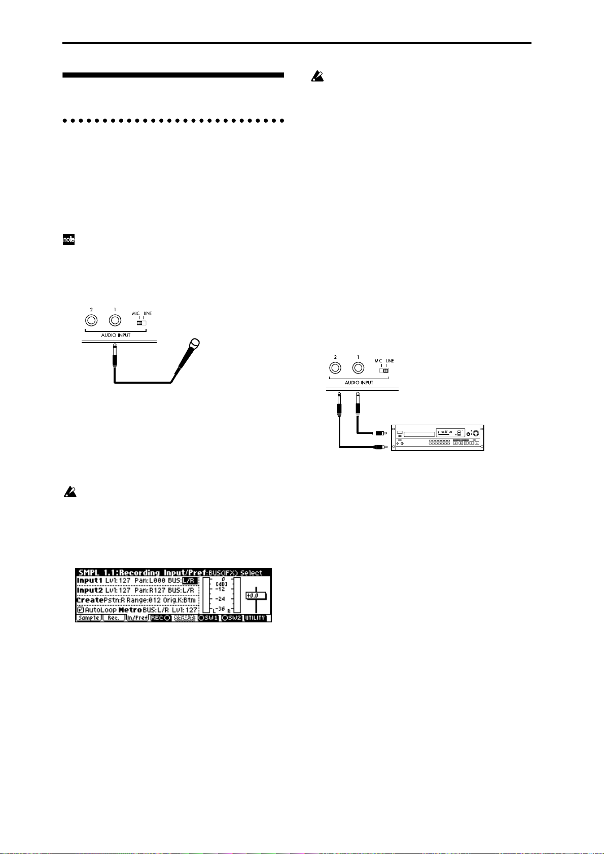
Sampling
Be aware that when you change the setting from
Off to L/R or IFX1–5, the volume level in the
AUDIO OUTPUT L/MONO and R jacks and in
the headphones may rise excessively.
Preparations for sampling
Connections and settings for a monaural
source
When sampling in monaural from a mic, the output of
an external audio device or mixer, or an instrumental
sound such as guitar or synthesizer , connect the sour ce
to the AUDIO INPUT 1 or 2.
Guitars and other instruments with active pickups
can be input directly, but instruments with passive
pickups (i.e., without internal preamps) cannot be
recorded at an appropriate level, due to impedance
mismatching. When connecting such instruments,
use a preamp or effect device.
TRITON-Rack
Mic
1 Connect the mic or external audio device to the
AUDIO INPUT 1 jack.
2 Set the AUDIO INPUT [MIC/LINE] switch to
match the input source. For input sources with a
low input level, such as a microphone, select the
MIC position. For other sources, select the LINE
position.
The AUDIO INPUT [MIC/LINE] switch affects
both the AUDIO INPUT 1 and 2 jacks.
3 The [INPUT] knob will be adjusted later. For now,
set it near the center.
4 In Sampling mode 1.1 Recording, select the Input/
Ptef page.
“Input 1” controls the AUDIO INPUT 1 jack, and
“Input 2” controls the AUDIO INPUT 2 jack.
The settings up to this point will cause the sound
from the AUDIO INPUT 1 jack to be output from the
AUDIO OUTPUT L/MONO jack and from the L
channel of the headphones.
6 Use the [INPUT] knob to set an appropriate level.
If an overload occurs in the input stage of the TRITON-Rack, “ADC OVER!” (AD converter overload!)
will be displayed above the “Recording Level”
slider. Adjust the [INPUT] knob or the output level
of the external audio device just low enough so that
the “ADC OVER!” does not appear (i.e., the maximum level that does not cause an overload).
Connections and settings for a stereo source
When sampling in stereo from a stereo mic, the output
of an external audio device or mixer, or synthesizer,
connect the source to the AUDIO INPUT 1 and 2 jacks.
TRITON-Rack
CD player,
analog record player etc.
L
LINE OUT
R
1 Connect the L source to AUDIO INPUT jack 1, and
the R source to jack 2.
2 Make the settings described in steps 2–4 of
“Connections and settings for a monaural source.”
3 Set the “Input 1” and “Input 2” parameters to spec-
ify how the signal from the AUDIO INPUT jacks
will be input to the TRITON-Rack.
• “Lvl” adjusts the volume. Set both Input 1 and
Input 2 to 127.
• “Pan” adjust the panning. Set Input 1 to L000, and
Input 2 to R127.
• Set “BUS.” For this example, select L/R for both
Input 1 and Input 2.
5 In “Input 1,” set various parameters to specify how
the signal from the AUDIO INPUT jacks will be
input to the TRITON-Rack.
• “Lvl” adjusts the volume. Normally you will set
this to 127.
• “Pan” adjust the panning. For this example set it to
L000.
• Set “BUS.” If you wish to use the TRITON-Rack’s
insert effects to process the incoming sound, select
IFX1–5 here. For this example, select L/R. The input
sound will be sampled just as it is.
68
The settings up to this point will cause the sound
from the AUDIO INPUT 1 and 2 jacks to be output
in stereo from the AUDIO OUTPUT L/MONO and
R jacks and from the headphones. The sound of
AUDIO INPUT 1 will be output from the left, and
AUDIO INPUT 2 from the right.
4 Use the [INPUT] knob to adjust a suitable input
level. (Refer to step 6 of “Connections and settings for a monaural source”)
The [INPUT] knob adjusts both AUDIO INPUT 1
and 2.
Page 75

Using an insert effect
The TRITON-Rack’s insert effects can be applied to the
sound that is being input from the AUDIO INPUT 1
and 2 jacks, allowing you to record a sample with
effects applied. As an example, we will explain the procedure for applying an insert effect to a stereo source
and sampling the result.
1 Make the settings of step 1 and 2 in “Connec-
tions and settings for a stereo source.”
2 Set the various “Input 1” and “Input 2” parame-
ters.
• Set “BUS” to IFX1 for both Input 1 and 2.
• Set “Lvl” and “Pan” to the same settings as in step
3 of “Connections and settings for a stereo
source.” With these settings, the stereo source will
be sent to insert effect 1 (IFX 1).
3 Use the [INPUT] knob to adjust a suitable input
level. (Refer to step 6 of “Connections and settings for a monaural source.”)
4 Select the 7.2: Insert Effect, Setup page.
Up to five insert effects can be connected in series.
Make settings for “Insert Effect,” “Chain,” and the
“Pan (CC#8)” of the sound after it has passed
through the insert effect. (
Examples of settings using the insert effects are
given in “Mode (Sample Mode)” (
☞PG p.28, 104)
☞PG p.77).
Manual sampling
Immediately after the power is turned on, 000:
NewMS______000 will be created automatically.
Use the numeric keys [0]–[9] to input the multisample number that you wish to record, and press the
[ENTER] key.
If you select a new number, the Create New Multisample dialog box will appear . Press the [F8] (“OK”)
key, and the new multisample will be created.
To specify the name, use the Utility “Rename MS.”
5 In “SMPL (Sample Select),” select the sample that
you wish to record. For this example, select ----: --No Assign----.
Immediately after the power is turned on, this will
be set to ----: ---No Assign----. You may sample even
in this condition. The sample will be automatically
recorded to a vacant sample number.
If you wish to start by specifying the sample number to be sampled, use the [INC], [DEC] keys or
numeric keys [0]–[9] and [ENTER] key to specify the
desired number.
A sample will be created when you record. A sample name such as 0000: NewSample_0000 will be
assigned automatically. This name can be edited
using the Utility “Rename SMPL.”
If you execute sampling when an existing sample
such as 0000: NewSample_0000 is selected, the new
sample will be sampled to a vacant sample number .
You do not need to be concerned with this setting
even when you continue recording successive samples.
6 Select the 1.1: Recording, Recording page.
Basic functions
There are two methods of sampling: manual and auto.
In manual mode, sampling is started by pressing the
[F5] (“START”) key from the recording standby condition (entered by pressing the [F4] (“REC”) key once).
For the sampling procedure in auto mode, refer to
“Auto sampling” (☞p.70).
1 Select the 1.1: Recording, Recording page.
2 For “Mode (REC Mode),” select Manual.
This will select manual recording mode.
3 Select the 1.1: Recording, Sample page.
4 For “MS (Multisample Select),” select 000:
NewMS____000.
Sampling mode
7 Set the “Mode (Sample Mode).”
Monaural source: If the “Input1” setting “Pan” is
L000, set “Mode (Sample Mode)” to L-Mono. If
“Pan” is R127, set “Mode (Sample Mode)” to RMono.
Stereo source: Set the “Mode (Sample Mode)” to
Stereo.
8 Press the [F4] (“REC”) key.
If an input signal is present, the Recording Level
[dB] meter will move according to the Pan setting in
“Input1” and “Input2.” This is the recordingstandby condition.
In the case of “Connections and settings for a monaural source,” the L meter will move. In the case of
69
Page 76

“Connections and settings for a stereo source,” the L
and R meters will move.
Use the “Recording Level [dB]” slider to adjust the
level. For this example, set the slider to the 0.0 set-
ting (
☞PG p.78).
9 At the moment that you wish to begin sampling,
press the [F5] (“START”) key.
Sampling will begin.
0 Sampling will stop when you press the [F5]
(“STOP”) key.
Sampling will stop automatically when the
remaining amount of memory reaches zero.
A Either press the [AUDITION] key, or press the C2
key on a connected MIDI keyboard.
The sample you recorded will play back.
If you wish to continue recording samples, repeat
steps 7–0.
Auto sampling
There are two ways to record a sample: manual and
auto.
With auto, sampling will begin when the input signal
exceeds the specified threshold level.
1 Select the 1.1: Recording, Recording page.
9 Press the [F4] (“REC”) key.
0 Press the [F5] (“START”) key.
When the input signal exceeds the “Threshold”
level, sampling will begin automatically.
A Sampling will stop when you press the [F5]
(“STOP”) key.
Sampling will end automatically if the remaining
amount of memory reaches zero.
B Either press the [AUDITION] key, or press the C2
key on a connected MIDI keyboard.
The sample you recorded will play back.
Creating multisample indexes and
sampling
Here’s how to create indexes for a multisample, and
assign a sample to each index.
If desired, you can first create several indexes for a
multisample, and then record a sample for each index.
1 Select the 1.1: Recording, Sample page.
Keyboard & Index
Index MS(Multisample Select)
2 For “Mode (REC Mode),” select Auto.
This will select auto recording mode.
3 Set the “Threshold.”
When the input signal exceeds the “Threshold”
level, sampling will begin automatically. The black
triangles at both sides of the Recording Level [dB]
meter display will indicate the specified level.
When you use auto sampling, the attack portion of
the sampled input sound may be lost, depending
on the “Threshold” setting. If this occurs, you can
use “Pre Trigger” to sample the sound that occurs
before sampling actually begins. Normally you
will set this to 0, and use it only when necessary.
4 Select the 1.1: Recording, Sample page.
5 Select the “MS (Multisample Select).”
☞“Manual sampling” step 4)
(
6 Select the sample in “SMPL (Sample Select)” that
you wish to record.
☞“Manual sampling” step 5)
(
7 Select the 1.1: Recording, Recording page.
8 Set the “Mode (Sample Mode).”
☞“Manual sampling” 6 7)
(
Create
2 Select “MS (Multisample Select),” and create a
multisample. (Refer to “Manual sampling” 4 )
3 Press the [F6] (“Create”) key to create an index.
Immediately after the power is turned on, the
“Index” will be indicated as 001/001. This means
that there is only one index. The range that is highlighted in the keyboard & Index is the range of the
selected index.
Press the [F6] (“Create”) key several times. Each
time you press it, an index will be created. The keyboard display will indicate the zone and original
key location of each index. The highlighted area is
the currently selected index.
The index that is created when you press the [F6]
(“Create”) key is created according to the “Create
(Create Zone Preference)” settings of the 1.1:
Recording, Input/Pref page. (
☞PG p.79, p.102).
70
Page 77

Immediately after the power is turned on, “Pstn
(Position)” will be R (Right), “Range (Zone
Range)” will be 012(Keys), and “Orig.K (Original
Key Position)” will be Btm (Bottom), so that
indexes will be created as shown below.
If you set “Range (Zone Range)” to 1(Key), an
index will be created for each note of the keyboard
and a sample assigned to in index. You can then
continue sampling. It is convenient to use 1(Key)
when you wish to sample numerous takes in succession, such as when recording phrases or rhythm
loops.
Loop settings
With the default settings after the power is turned on,
the sounds you sample will automatically be looped
(1.1: Recording, Input/Pref page “AutoLoop (Auto
Loop On)” On)
T o edit the loop and other playback address settings for
the sample, use the 3.1: Loop Edit, Edit2 page.
1 Select the sample for which you wish to make loop
settings.
To select the sample, use the “SMPL (Sample
Select)” or “Index” parameters of 3.1: Loop Edit,
Edit 1 page or of the 1.1: Recording, Sample page.
(☞p.70)
If you use “SMPL (Sample Select)” to select the
sample, be aware that the assignment to the index
will also change.
4 Select “Index.”
“Index” can also be selected by holding down the
[ENTER] key and playing a note on a connected
MIDI keyboard. For this example, select 001.
5 If you have been sampling previously and one or
more samples already exist, use “SMPL (Sample
Select)” to select the sample that you wish to
assign.
Repeat steps 4 and 5 to assign a sample to each
index. Complete the multisample in this way.
To hear the sampled sound, play a note on a connected MIDI keyboard in the range of the index to
which the sample is assigned, or press the [AUDITION] key.
6 Alternatively, you can create several indexes for
the multisample before you begin sampling, and
then sample for each index.
In step 4, select the index for which you wish to
sample, and use either manual sampling or auto
sampling to record a sample. (
“Auto sampling”)
Create a multisample by selecting an index and then
sampling.
The number and order of the indexes in the multisample, the zone of each index, and the original
key location can be edited later if desired (☞p.74
“Multisample editing”).
☞“Manual sampling,”
2 In the 3.1: Loop Edit, Edit1 page, use the “Lp
(Loop)” check box to turn loop playback on/off for
the sample.
Looping will be turned on if the box is checked.
This will operate between the addresses you specify
in step 4.
Loop On: S→E→LpS→E→ (LpS→E is repeated)
Loop Off: S→E
3 Select the 3.1: Loop Edit, Edit2 page.
The waveform data of the currently selected sample
will be displayed. You can play back the sample by
playing a note on a connected MIDI keyboard in the
range of keys to which the sample is assigned (the
keyboard area highlighted in “Keyboard & Index”).
You can also play the sample by pressing the
[AUDITION] key.
In the case of a sample that was sampled with a
“Mode (Sample Mode)” setting of Stereo, the
waveform display will alternate between L and R
each time you press the [F3] (“L/R”) key. At this
time, the upper right of the display will indicate
[L] or [R].
Basic functions
Sampling mode
4 Specify the start address in “S (Start),” the loop
start address in “LpS (Loop Start),” and the end
address in “E (End).”
Select “S (Start)” (highlighted), and use the [V ALUE]
dial or other V ALUE contr ollers to modify the value.
The corresponding vertical line will move. Set “LpS
(Loop Start)” and “E (End)” in the same way. In the
example shown below , “S (Start)” is set immediately
71
Page 78

before the first waveform, “LpS (Loop Start)” is set
immediately before the second waveform, and “E
(End)” is set as desired.
S (Start) LpS (Loop Start) E (End)
Check “Grid,” set “Resolution” as desired, and
press the [F8] (“OK”) key. The dotted grid lines will
appear.
By using the ZOOM ([F4] key–[F7] key) you can
change the range that is displayed. When “S
(Start)” is highlighted, zoom will be performed
from the start address (
If the “Zero (Use Zero)” check box is checked, only
those addresses where the waveform data crosses
the zero level will be found automatically when
searching, and can be set. This lets you easily make
address settings where noise is less likely to occur
when looping.
5 If necessary, use the Utility “Truncate” to delete
unwanted data that falls outside the start (or loop
start) and end addresses.
Set the parameters, and press the [F8] (“OK”) key
to execute the operation. (
☞PG p.85).
☞PG p.93)
2 Set “ (Grid Tempo)” to the desired BPM tempo
value.
3 Set the end address so that it coincides with a dot-
ted line of the grid.
This will cause the loop interval to be the same
length as the BPM value.
The grid display will be based at “LpS (Loop Start)”
if looping is on. If looping is off, the grid will be
based at “S (Start).”
4 To hide the grid display, select the “Grid” utility,
uncheck “Grid,” and press the [F8] (“OK”) key.
The grid is displayed according to the playback
pitch of the base key (the key shown in gray in the
“Keyboard & Index” area).
You can select the base key by holding down the
[ENTER] key and playing a note on the keyboard
of a connected MIDI instrument.
For cautions on the “Save to No.” and “Overwrite”
check boxes, refer to “A note on saving samples”
(☞p.73).
The grid display
The Utility “Grid” overlays the waveform display with
a grid based on the BPM tempo value. This makes it
easy to make loop settings that are synchronized to the
tempo.
In the same way, the grid display can also be used
in 2.1: Sample Edit, Edit2 page. The grid can help
you to edit the waveform in synchronization with
the tempo.
1 Select the “Grid” Utility.
The following dialog box will appear.
72
Page 79

Sample (waveform data) editing
Editing the waveform data of the sample is done in 2.1:
Sample Edit. You can use commands such as cut, copy,
and normalize to edit the waveform data.
1 Select the sample that you wish to edit.
Use “SMPL (Sample Select) or “Index” in the 2.1:
Sample Edit, Edit 1 page or the 1.1: Recording, Sample page to select the sample. (☞p.70)
If you use “SMPL Sample Select)” to select the
sample, be aware that the index assignment will
also change.
2 Select the 2.1: Sample Edit, Edit2 page.
The waveform data of the currently selected sample
will be displayed.
The waveform display of a sample that was sampled with a “Mode (Sample Mode)” setting of Ste-
reo can be switched between the L and R
waveforms by pressing the [F3] (“L/R”) key. When
you do so, [L] or [R] will be displayed alternately
in the upper right.
A note on saving samples
In the dialog boxes of some Utility menu, there is a
“Save to No.” setting that lets you specify the sample
number to which the edited sample will be saved. At
this time, a vacant sample number will be selected
automatically, so you will change the setting only if
you want to specify the save destination number.
If you check “Overwrite” in the dialog box of the command, the data prior to editing will be deleted, and will
be overwritten by the edited data. Normally, you will
execute the Write operation without checking this, so
that the unedited data is preserved. When you are completely finished with your editing, you can use the
“Delete SMPL” utility to delete unneeded samples.
In Sampling mode, there is no Compare function
that lets you compare the data before and after
editing.
If you wish to preserve the unedited state of the
multisample or sample, use “Copy SMPL” or
“Copy MS” (
ple or sample before you begin editing it.
For some Utility menu commands in 2.1: Sample
Edit or 3.1: Loop Edit, you can execute without
checking the “Overwrite” setting in the dialog
box, so that the sample data previous to editing
will be preserved.
☞PG p.80, 81) to copy the multisam-
Basic functions
3 Use “Edit S (Edit Range Start)” and “Edit E (Edit
Range End)” to specify the range that you wish to
edit.
The selected range will be highlighted.
If you wish to hear the sound of the selected range,
press the [AUDITION] key. The selected range will
play back at the pitch of the base key (the key shown
in gray on the keyboard display). You can select the
base key by holding down the [ENTER] key and
playing a note on your keyboard.
On your connected MIDI instrument, play a key to
which the sample is assigned (the highlighted range
of the keyboard displayed in “Keyboard & Index”),
and the sample will be played back according to its
loop settings.
The procedure for using the ZOOM and “Zero
(Use Zero)” check boxes is the same as for 3.1:
Loop Edit.
4 From the list of Utility menu, select the desired
editing command. Make the appropriate settings
in the dialog box, and press the [F8] (“OK”) key to
execute.
For details on each command (
☞PG p.84).
Sampling mode
73
Page 80

Multisample editing
Editing a multisample is accomplished with a number
of operations i.e. creating indexes for the multisample
and assigning a sample to each index, editing operations such as deleting, copying, and inserting indexes,
and detailed settings such as sample level and pitch for
each index.
Multisample editing is performed in 4.1: Multisample.
Basic settings such as creating indexes and assigning samples can also be made in the 1.1: Recording,
Sample page.
Editing the indices
To change the number or order of the indexes, use the
Insert, Cut, Copy, and Create.
1 Select 4.1: Multisample.
2 Use “MS (Multisample Select)” to select the multi-
sample that you wish to edit.
3 Select the “Index.”
You can also select this by holding down the
[ENTER] key and playing a note on a connected
MIDI instrument.
4 Press the keys corresponding to the following
function buttons to edit the multisample by changing the number or order of the indexes.
To delete the selected index, press the “Cut.”
The “Insert” is used in conjunction with the Cut and
“Copy.” The contents of the index that was Cut or
Copied will be inserted.
The “Create” has the same function as the “Create”
in 1.1 Recording, Sample (☞p.70 “Creating multisample indexes and sampling”).
Adj.” to set the loop interval to a desired BPM
value (
☞PG p.102).
Converting a multisample to a program
The “Conv. To Prog” utility can be selected and executed in the various pages of 1.1: Recording, in 2.1:
Sample Edit, in Edit 1 of 3.1: Loop Edit, in the various
pages of 4.1: Multisample, and in 5.2: Ctrl Setup. When
you execute this utility, the state of the currently
selected multisample will be converted into a program.
In Program mode you can make filter, amp and effect
settings etc., and play the sample as a program. The
resulting program can be used in a combination or
multi.
For details on using the “Conv. To Pr og” utility, refer to
p.32 and PG p.83.
Using samples in a drum kit
A sample you created in Sampling mode can be used as
one of the instruments in a drum kit. In the GLOBAL
5.1: DKit, High Sample page and Low Sample page, set
“Drumsample Bank” to RAM, and use “Drumsample”
to select the sample that you created.
Modifying the settings of an index
1 Make the settings described in steps 1–3 of
“Editing the indices.”
2 Set parameters for the selected index.
☞PG p.101)
(
• Changing the Edit1 page “Top K (Top Key)” will
change the upper limit of the zone. Simultaneously,
the lower limit of the next-numbered index will
also change.
• If you check “Constant Pitch” in the Edit2 page,
playing any note on a connected MIDI instrument
within the zone of an index will always sound the
original pitch.
• Edit2 page “Pitch” adjusts the sample pitch for
each index. You can use the Utility “Pitch BPM
74
Page 81

Using Time Slice to divide a sample, and playing it in Multi mode
RPPR
Press the [F8] (“OK”) key. The Set Sample Tempo
dialog box will appear.
Time Slice is a function that detects the attack of the
kick or snare etc. in a rhythm loop sample (a sample
consisting of a looped pattern of drums etc.), and automatically divides it into separate instrumental sounds.
Each of the divided instrumental sounds is made a
sample of its own, and then automatically expanded
into a multisample and program. Pattern playback data
for Multi mode and RPPR settings for the divided samples are also created automatically. (
The time-slices sample can be used in the following
ways by the RPPR function of Multi mode.
• Multiple rhythm loop samples of differing tempo
can be matched to the same tempo without
changing their pitch.
• You can change the tempo in realtime without
affecting the pitch.
• Multiple rhythm loop samples can be turned on/
off in realtime from the keyboard of a connected
MIDI instrument.
As an example, we will explain the procedure for using
Sampling mode to time-slice two rhythm loop samples,
and using the RPPR function of Multi mode to play
them as rhythm loop samples.
☞PG p.93)
Time Slice
You will need to provide rhythm loop samples of
drums etc. You can either record these on the TRITONRack, or load them in Disk mode. Initially, you should
try this using a one-measure pattern in 4/4 time with a
fairly simple beat, and record the pattern as a monaural
rhythm loop sample.
For this example, we will use a 140 BPM rhythm loop
sample and a 100 BPM rhythm loop sample.
1 Select “SMPL (Sample Select)” 140 BPM rhythm
loop sample.
4 Specify the number of quarter-note beats in the
sample, and its tempo.
If you know the BPM, set “Source BPM.”
If you do not know the BPM, set “Beat” and the
BPM will be calculated automatically. Since in this
example we do know the beat, set “Source BPM” to
140.
5 Press the [F8] (“OK”) key.
The sample will automatically be sliced, and a dialog box will appear.
When you play the keyboard of a connected MIDI
instrument, C2 will play the original sample
(Source), and D2 and subsequent keys will play the
divided sample. You can change “Index” and press
the [AUDITION] key to play the sample that is
selected by “Index.”
While listening to each divided sample, adjust “Sensitivity” so that each drum strike or other rhythm
instrument sound is divided into its own sample. In
some cases, it may not be possible to slice the sample cleanly even if you adjust “Sensitivity.” If the
attack of the next sound is included in the end of the
preceding sample, or if one sample contains two
notes, you will need to edit the samples. (
6 Press the [F6] (“Save”) key.
The save dialog box will appear.
☞PG p.95)
Basic functions
Sampling mode
2 Access the SMPL 3.1: Loop Edit, Edit 2 page.
3 Select and execute the “Time Slice” utility.
Press the [F8] (“UTILITY”) key to access the Utility
menu, and press the [F7] key to select “Time Slice.”
Here you can save the time-sliced sample and the
automatically-created multisample. You can set the
“With” items to specify the save destination for the
program that uses the samples and multisample,
and the pattern data for the rhythm loop sample
used by the RPPR function of Multi mode.
For this example, set the “With” items as shown in
the illustration.
Set “Program,” “Seq. Event,” “RPPR” to On
(checked)
Program: I-E010
Multi: 000, Pattern: U00
RPPR Key: C#2, Track: 01
Press the [F8] (“Save”) key to execute the save
operation, and you will return to the dialog box of
step 5. Press the [F7] (“Exit”) key to return to the
screen of step 2.
75
Page 82

7 Next use “SMPL” to select the 100 BPM rhythm
loop sample.
Repeat steps 2–5 to execute Time Slice and make
any necessary adjustments.
In step 4, set “Source BPM” to 100.
8 As in step 6, press the [F6] (“Save”) key.
The save dialog box will appear.
•5.1: RPPR, RPPR KEY: D2, Assign: On, Pattern:
User U01, Track: 02 (set in step
8)
After making sure that RPPR is turned on, play C#2
and D2 on the keyboard of the connected MIDI
instrument, and the time-sliced samples will play
back at the tempo specified by “ (Tempo)” without
their pitch being changed.
For example if you set “ (Tempo)” to 120, the 140
BPM rhythm loop sample of C#2 and the 100 BPM
rhythm loop sample of D2 will both play at a tempo
of 120 BPM.
Set the MIDI channel of the connected MIDI
instrument to match the MIDI channel selected for
“Control Track.” By default, the multi will use
channel 1.
If, when you change the tempo, the beat of the
rhythm loop sample is not reproduced correctly or
noise is obtrusive, the slice has not been sliced
optimally in step 5. The precision at which the
rhythm instruments are divided will have a major
impact on the quality of the playback. Please
adjust the divisions of each sample in step 5.
(
☞PG p.95)
For this example, set the “With” items as shown in
the illustration.
Set “Program,” “Seq. Event,” “RPPR” to On
Program: I-E011
Multi: 000, Pattern: U01
RPPR Key: D2, Track: 02
Press the [F8] (“Save”) key to execute the save
operation, and you will return to the dialog box of
step 5. Press the [F7] (“Exit”) key to return to the
screen of step 2.
RPPR (Multi mode)
9 Press the [MULTI] key to enter Multi mode, and
select Multi: 000.
The following multi data that you specified in steps
6 and 8 will be specified and created automatically.
•1.1: Play, Multi Multi: 000, “RPPR On/Off” On
•1.1: Play, Prog..8 Track 01 Program: I-E010 (set in
step 6)
•1.1: Play, Prog..8 Track 02 Program: I-E011 (set in
step 8)
•5.1: RPPR, Pattern Pattern: U00 (created in step 6)
•5.1: RPPR, Pattern Pattern: U01 (created in step 8)
•5.1: RPPR, RPPR KEY: C#2, Assign: On, Pattern:
User U00, Track: 01 (created in
step 6)
If the silent portion between the samples is obtrusive when you play back at a slower tempo, or if
noise occurs between the samples when you play
back at a faster tempo, the result may sound
unnatural. To avoid such problems, you can execute Time Stretch to adjust the length of the individual samples to match the desired playback
tempo in steps 6 and 8. (
Depending on the end address settings etc. of the
sample to be sliced, the number of measures in the
pattern may increase, or the pattern playback in
Multi mode may not loop accurately. In such cases,
use the Multi mode utility “Pattern Parameter”
(
☞PG p.64) to re-specify “Length.”
0 Settings for the RPPR function are made in the
MULTI 5.1 RPPR, RPPR Setup page.
Use “M (Mode)” to specify the pattern playback
mode that will be used when you play a note on a
connected MIDI instrument, and set “Sync” to specify the pattern playback timing/synchronization
mode when multiple keys are pressed. “Shift” is
normally set to +00. (
☞PG p.96 9)
☞PG p.65)
76
Page 83

Global mode
In Global mode you can make settings that affect the
entire TRITON-Rack, such as user scales, category
names, drum kits, and user arpeggio patterns (
p.107).
This chapter will describe the procedure for editing a
drum kit. For the procedure of editing an user arpeggio
pattern, refer to “Arpeggiator settings” (☞p.85). For
details on the parameters of other pages (☞p.99).
In Global mode, playing the keyboard of a connected MIDI instrument will cause the TRITONRack to sound in the state of the previouslyselected mode. If you move from Sampling mode
to Global mode when sample memory is empty
(such as immediately after the power is turned on),
be aware that the TRITON-Rack will not produce
sound.
The settings that you edit in Global mode are preserved as long as the power remains on, but will be
lost when the power is turned off.
The data handled in Global mode can be classified
into three types: drum kit settings (GLOBAL 5.1),
user arpeggio pattern settings (GLOBAL 6.1), and
all other global settings (GLOBAL 1.1–4.1). Each
of these three types of data can be written into the
memory area. In Disk mode, this data can also be
saved on external media such as a floppy disk
(☞p.40).
☞PG
Creating a drum kit
About drum kits
A drum kit assigns a drumsample (PCM waveform
data for a drum) to each key, and specifies adjustments
in pitch and level etc. for each sample.
The TRITON-Rack contains 144 drum kit memory
areas. With the factory settings, 00 (I–A/B) – 15 (I–A/B)
contain preloard drum kits suitable for various styles
of music. ROM memory areas 144 (GM) – 152 (GM)
contain nine different preset drum kits compatible with
the GM2 sound map.
For the factory preset drum kits, refer to the separate
“VNL.”
In GLOBAL 5.1: DKit you can modify these drum kits,
or create your own original drum kit from an initialized condition. You can also create original drum kits
using sample waveforms that you sampled in Sampling mode or loaded into memory in Disk mode.
A drum kit that you edit or create can be written into
one of the user drum kit memory areas 00 (I–A/B) – 143
(E–H). In Disk mode, you can save drum kits on external media such as a floppy disk.
Basic functions
Global mode does not provide a Compare function
that lets you make before-and-after comparisons of
your editing. Before editing user drum kits, or user
arpeggio patterns, you may wish to use “Copy
Drum Kit” or “Copy Arpeggio Pattern” to copy the
user drum kit or user arpeggio pattern to an
unused number.
Multisample programs and drum kit programs
There are two types of programs: those whose oscillator uses a multisample, and those whose oscillator
uses a drum kit.
This selection is made by the PROG 2.1 Ed-Basic, Prog
Basic page “Mode (Oscillator Mode)” setting. To use a
multisample for the program, set “Mode (Oscillator
Mode)” to Single or Double. To use a drum kit, set
“Mode (Oscillator Mode)” to Drums.
About program parameters
Just as the character and effect processing of a melodic
instrument such as piano, organ, trumpet, and strings
is fundamentally different from that of percussion
instruments such as drums or timpani, the program
parameter structure of a multisample program (“Mode
(Oscillator Mode)” to Single or Double) is fundamentally different from that of a drum kit pr ogram (“Mode
(Oscillator Mode)” to Drums).
The program parameters of a multisample specify filter
and amp settings etc. appropriate for a multisample.
For this reason, it is difficult to change such a program
for use with a drum kit. Thus if you wish to edit a
drum kit, you should first use Program mode to select
a program that uses a drum kit (“Mode (Oscillator
Mode)” = Drums), and then move to the GLOBAL 5.1:
DKit page. Programs that use a drum kit have filter,
amp, and effect settings suitable for drum sounds. It is
Global mode
77
Page 84

best to first select a drum kit program in Program
mode, and then do your editing in Global mode.
Editing a drum kit
Before editing a drum kit, uncheck the Memory
Protect (☞p.37).
1 In PROG 1.1: Play, select the program that you
wish to use while editing the drum kit.
Select a drum kit program from the preload programs etc. If the drum kit that you will be editing is
already being used by a program, select that program. (In the separate “VNL,” programs that use a
drum kit are marked by a symbol.)
Set “Octave” to +0 [8']. W ith a setting other than +0
[8'], the relation between the keys and the sounds
will be incorrect.
The effects will sound using the settings of the lastselected program.
When you edit a drum kit, all programs that use
that drum kit will be affected.
2 Access the High Sample page of GLOBAL 5.1:
DKit.
d
5 Use “Assign” to specify whether a drum sample
will be assigned to the note number.
If this is checked, a drum sample will be assigned to
that note number. Normally you will check this.
If this is not checked, no drum sample will be
assigned to that note number . That note number will
sound the drum sample assigned at its right, but a
semitone lower. Use this setting when you want
only to change the pitch, such as with tom or cymbal
sounds.
6 Use “Drumsample Bank” and “Drumsample” to
select the drum sample that will be assigned to the
note number.
Set the High Drumsample in the High Sample page,
and the Low Drumsample in the Low Sample page.
If you specify a Low Drumsample, use “Vel.SW
L→H” to specify how velocity will switch between
the High Drumsample and the Low Drumsample.
(
☞7)
By setting “Drumsample Bank” to ROM you can
select ROM drum samples, to RAM to select sampled or loaded samples, or to EXB* to select drum
samples from a separately sold EXB-PCM series
option.
Some EXB-PCM series boards do not contain
drumsamples.
3 In “Drum Kit,” select the drum kit that you wish to
edit.
If necessary, use the Utility “Copy Drum Kit” to
copy settings from a preload drum kit or a GM
drum kit.
GM drum kits 144 (GM) – 152 (GM) cannot be
selected here. (It is not possible to edit or write a
GM drum kit.) If you wish to modify the settings
of one of the drum kits 144 (GM) – 152 (GM), you
can use “Copy Drum Kit” to copy it to 00 (I–A/B) –
143 (E–H), and then edit the copy.
4 Use “Key” to select the note number that you wish
to edit.
The drum sample parameters for the selected note
number will be displayed in the High Sample, Low
Sample, and Voice/Mix pages. In addition to using
the VALUE controllers, you can also use the following methods to select the note number.
• Hold down the [ENTER] key and play a key on a
connected MIDI keyboard to input that note
number.
• Use the [F6](“Key–”) and [F7](“Key+”) keys to
increment or decrement the note numbers.
About ROM drumsamples
The TRITON-Rack contains 413 drumsamples in its
internal ROM memory.
You can use the “Select by Category” utility to select
ROM drum samples from fifteen categories.
For the drumsample names, refer to the separate
“VNL.”
7 Use “Vel. SW L→H” to specify how velocity will
switch between drumsamples.
The drumsample that sounds when you perform
will depend on the velocity (keyboard playing
strength) of the incoming note. This is called veloc-
ity drumsample switching.
If you set this to 001, only the High Drumsample
will sound.
☞ This is the same type of function as the Velocity
Multisample Switching in a program. (☞p.44 “High
Multisample and Low Multisample”)
8 Set the parameters of the drumsamples that you
assigned.
Set the High Drumsample parameters in the High
Sample page, and the Low Drumsample parameters
in the Low Sample page.
You can set parameters such as volume level
(“Level”), pitch (“Trans,” “Tune”), and tone (“Fc,”
“Reso”).
For details on each parameter, refer to PG p.116.
9 As necessary, repeat steps 4–8 to set drumsample
parameters for each note number.
78
Page 85

If you wish to use the settings of another “KEY,”
select the “Copy Key Setup” utility.
0 Select the Voice/Mixer page in GLOBAL 5.1: DKit.
A Set the “Excl Group.”
The “Excl Group” setting is used when you wish to
group drumsamples of the same type.
For example if the note number to which a open hihat and a closed hi-hat drumsample are assigned are
set to the same exclusive group number , they will be
grouped so that the open hi-hat and closed hi-hat
can not be sounded simultaneously, ensuring that
the hi-hat performance will sound natural.
B Use “BUS” to specify the output routing.
Set this when you wish to send the output of the
drumsample assigned to each note number to its
own insert effect or AUDIO OUTPUT (INDIVIDUAL) jack 1–4.
For example you might set snare-type sounds to
IFX1 and kick sounds to IFX2, so that these sounds
would be sent to insert effects 1 and 2 respectively. If
you wish to send only specific drumsamples to
AUDIO OUTPUT (INDIVIDUAL) jacks 1–4, select
1–4, 1/2, or 3/4.
These settings are valid if “Use DKit Setting” (PROG
7.1: Ed-BUS, BUS page) is checked in the Routing
tab of Program P8 for the program that uses this
drum kit (
C Use “Pan” to specify the stereo output position.
The setting you make here is valid if the “Use DKit
Setting” is checked (PROG 5.1: Ed-Amp1, Level/
Pan page) for the program that uses this drum kit.
D Use “S1 (Send1(MFX1))” and “S2 (Send2(MFX2))”
to set the send levels to the master effects.
The settings you make here are valid if the “ Use
DKit Setting” is checked (PROG 7.1: Ed-BUS, BUS
page) for the program that uses this drum kit.
E Use the “Write Drum Kits” utility to save the data.
If you wish to change the name of the drum kit
before you save it, use the “Rename Drum Kit” utility (☞p.38).
If you turn off the power before writing the data into
memory, your edits will be lost (☞p.39 “Memory in
Global mode”).
☞PG p.27, 143, 144).
Basic functions
Global mode
79
Page 86

Disk mode
How Disk mode is organized
In Disk mode you can use floppy disks or a connected
external SCSI device (if the separately sold EXB-SCSI is
installed) to save or load various types of data. You can
also make settings related to saving and loading functionality.
For details on connecting an external SCSI device and
setting the SCSI ID etc., refer to the owner’s manual for
the separately sold EXB-SCSI option.
Types of media that can be used
Floppy disks
The TRITON-Rack can use MS-DOS format 3.5 inch
2HD or 2DD floppy disks. The capacity of a floppy
disk after formatting will be 1.44 MB (18 sectors/track)
for a 2HD disk, or 720 KB (9 sectors/track) for a 2DD
disk. (
☞For details on formatting, refer to PG p.137.)
We recommend that you use 2HD floppy disks.
External SCSI storage media (when the separately sold EXB-SCSI option is installed)
If the separately sold EXB-SCSI option is installed, the
TRITON-Rack can save data on external SCSI media
(maximum 4 GB) such as a hard disk, Zip, Jaz, ORB, or
MO drive.
When the EXB-SCSI option is installed, an external
SCSI device of up to 4 GB can be formatted.
When you insert media for the first time after turning on the power, or after changing disks, you
must press a function key etc. to make the TRITON-Rack detect the media. When the disk (or
other media) is recognized, media information will
appear in the LCD screen.
Y ou can also make the TRITON-Rack r ecognize the
media by pressing the [SELECT], [ARP ON/OFF],
[AUDITION], or [DEMO/SNG] keys, or any key
other than the mode keys.
If more than one volume of media is currently recognized, select “Drive” and use the [INC], [DEC]
keys to switch between media.
The TRITON-Rack cannot format media with a format of other than 512 bytes/block (such as 640 MB,
1.3 GB MO disks etc.).
Files that can be loaded
DOS files
.PCG file
.SNG file
DOS directory Undefined DOS file
All programs
All combinations
All drum kits
All user arpeggio
patterns
Global settings
1 multi
[000–199]
1 program
bank [I-A–I-F, E-A–E-H]
1 combination
bank [I-A–I-E, E-A–E-H]
1 drum kit group
I-A/B, E-A–E-H]
1 user arpeggio
pattern group
[I-A/B, E-A–E-H]
Track
1 user pattern
[000–99]
Up Open
1 combination
1 user arpeggio
1 program
1 drum kit
pattern
DOS file
.MID file
.EXL file
.KMP file
.KSF file
.KSC file
.AIF file
.WAV file
AKAI format program file
AKAI format sample file
80
Page 87

Loading data
Types of data that can be loaded
The data that can be loaded from external media (e.g.,
floppy disk) is shown in the diagram at the bottom of
the previous page. (
refer to PG p.123)
If the separately sold EXB-SCSI option is installed, data
can also be loaded from media such as a hard disk or
CD-ROM.
Data loading procedure
Loading Programs, Combinations, Drum
kits, User arpeggio patterns, and Global settings (loading a .PCG file)
Select this when you wish to reload programs or combinations that you created and saved using “Save All”
or “Save PCG,” or when you wish to restore the preloaded data (factory settings) from the included floppy
disks.
Before loading programs, combinations, multis,
user drum kits, and user arpeggio patterns, you
must turn off memory protect in Global mode
(☞p.37).
Here, as an example, we will load the PRELOAD.PCG
file from the included floppy disk. A .PCG file contains
programs, combinations, drum kits, user arpeggio patterns, and global settings. (
ous page)
1 Insert the floppy disk “TNRFD-00P” into the
floppy disk drive of the TRITON-Rack.
For details on handling floppy disks, please be sure
to read “Cautions when handling floppy disks”
(☞p.84)
2 Enter Disk mode, and press a function key etc. to
make the TRITON-Rack detect the disk.
☞For details on each type of data,
☞lower diagram on previ-
When you load a .PCG file, the data in the internal
memory of the TRITON-Rack will be overwritten
with the data of that .PCG file (programs, combinations, drum kits, user arpeggio patterns, global
settings). If you wish to keep the data that is currently in internal memory, you must execute “Save
All” or “Save PCG” to save it before you load other
data.
5 From the utility menu, choose “Load Selected.”
A dialog box will appear. The dialog box and its settings and operation will differ depending on the
type of file that you load. For details on each file,
refer to PG p.123.
If you check “Load ********.SNG too” when loading, the .SNG file of the same name as the .PCG file
will also be loaded. If you check “Load
********.KSC too” when loading, the .KSC file of the
same name as the .PCG file will also be loaded.
(
☞PG p.125)
6 In “.PCG Contents,” specify the data that will be
loaded.
1)If you wish to load all the data of the .PCG file,
select All.
Normally you will select All. If you load PRELOAD.PCG from the included floppy disk using
All, all the data of the .PCG file will be loaded as follows.
Programs
• Bank I-A file: loaded to bank I-A
• Bank I-B file: loaded to bank I-B
• Bank I-C file: loaded to bank I-C
• Bank I-D file: loaded to bank I-D
• Bank I-E file: loaded to bank I-E
Basic functions
Disk mode
3 Select the Load page.
File information will be displayed in the LCD
screen.
4 Select a PRELOAD .PCG file.
The selected file will be highlighted in the display.
If the data you wish to load is located in a lower or
higher directory level, use [F6] (“OPEN”) or [F5]
(“UP”) keys to display the desired data, and then
select it.
Combinations
• Bank I-A file: loaded to bank I-A
• Bank I-B file: loaded to bank I-B
• Bank I-C file: loaded to bank I-C
• Bank I-D file: loaded to bank I-D
Drum Kits
• 00–15 (I-A/B) file: loaded to banks I-A/B
Arpeggio Patterns
• 000–199 (I-A/B) file: loaded to banks I-A/B
2)If you wish to load the data of the .PCG file by individual banks, use “.PCG Contents” to select the
load source bank, and “To” to select the load destination bank.
When you execute the load operation, only the pro-
grams, combinations, drum kits, and user arpeggio
patterns of the specified bank will be loaded to the
81
Page 88

specified load destination bank. Global setting data
will not be loaded.
If you set “.PCG Contents” to Bank I-A, and set
“To” to Bank I-A, the data will be loaded as follows.
When you load PRELOAD.PCG, any data that you
had written previously will be overwritten and
lost. If you do not want to lose your data, you must
first save it on a floppy disk etc. (☞p.40)
Programs
• Bank I-A file: loaded to bank I-A
Combinations
• Bank I-A file: loaded to bank I-A
Drum Kits
• 00–15 (I-A/B) file: loaded to banks I-A/B
Arpeggio Patterns
• 000–199 (I-A/B) file: loaded to banks I-A/B
If you specify different banks as the load source
and load destination, the data listed below will be
automatically reassigned so that the various types of
data will correspond correctly in each mode after
being loaded.
Even if “Load .SNG too” is checked when you load,
the data will automatically be reassigned so that the
multi data will correspond correctly.
• Program bank used by the combinations
• Pattern number of the user arpeggio pattern
used by the combinations/programs/multi
• Kit number of the drum kit used by the program
• Program bank used by each track of a multi
• If there are track/pattern events, the program
bank within the events
7 Press the [F8] (“OK”) key to execute the Load oper-
ation.
If the specified data does not exist in the file, the
load operation will be halted. (
Never remove the media while data is being
loaded.
☞PG p.125)
Contents of the included floppy disks
The TRITON-Rack comes with two floppy disks
(TNRFD-00P, TNRFD-01P).
The contents of these disks are as follows.
“TNRFD-00P”
PRELOAD.PCG (already loaded with the factory
settings)
• Programs (Bank I-A, I-B, I-C, I-D, I-E)
• Combinations (Bank I-A, I-B, I-C, I-D)
• Drum Kits (I-A/B: 16 kits)
• Arp Patterns (I-A/B: 200 patterns)
This is the preloaded data (programs, combinations,
drum kits, arpeggio patterns, and global settings).
Program bank I-E contains only I-E000–I-E004.
I-E000: Sampler Waves is a multisample program
used by the demo song. I-E001–I-E004 are programs
that use the vocoder effect (093: Vocoder).
PRELOAD.PCG can be loaded into the TRITONRack by the Disk mode utility “Load Selected.” This
data is preserved even when the power is turned off.
DEMOSONG.SNG (already loaded with the factory
settings)
• Demo songs (000...004)
This is demo song data for loading to DEMO/SNG.
It can be loaded into internal DEMO/SNG memory
by the Disk mode utility “Load to Demo Song.”
(☞p.42, PG p.132)
When you load DEMOSONG.SNG, the DEMO/
SNG and Multi data in the TRITON-Rack’s internal memory will be overwritten. If you do not
want to lose your data, you must first save it on a
floppy disk etc. (☞p.40). Since the arpeggio patterns and drum kit data in memory will also be
erased, you should write this data if you do not
want to lose it.
RPPRDEMO.SNG
• FEVER
This is RPPR data for loading into a multi. It can be
loaded into a TRITON-Rack multi by the Disk mode
utility “Load Selected.” (☞p.25, PG p.128)
When you load RPPRDEMO.SNG, the Multi data
in the TRITON-Rack’s internal memory will be
overwritten. If you do not want to lose your data,
you must first save it on a floppy disk etc. (☞p.40)
“TNRFD-01P”
DCUT_SMP.KSC
DCUT_SMP-folder
This is multisample and sample data used by the
demo song “Deep Cut.” (☞p.16, 29)
When DCUT_SMP.KSC is loaded, the “Select .KSC
Allocation” setting will affect how the data is
loaded into sample memory. (
☞PG p.130)
Loading .PCG files or .SNG files from the floppy
disks included with the separately sold EXB-PCM
series options
The floppy disk included with each EXB-PCM series
option contains PCG files and SNG files that match the
bank structure of the TRITON/TRITONpro/TRITONproX (keyboard models of the TRITON).
(As of July 2000)
C_BANK.PCG (.SNG) and D_BANK.PCG (.SNG) have
the same content, but use different banks.
C_BANK.PCG (.SNG) is for loading into bank C of a
keyboard model TRITON, and D_BANK.PCG (.SNG)
is for loading into bank D.
When loading these EXB-PCM series files into the TRITON-Rack, we recommend that you load them into
banks EXB-A–EXB-H.
As an example, here’s how to load the files of the
floppy disks included with the EXB-PCM01–04 into
banks E-A, E-B, E-C, and E-D of the TRITON-Rack as
follows.
82
Page 89

• Load the EXB-PCM01 file for bank C of the
TRITON keyboard model into bank E-A.
• Load the EXB-PCM02 file for bank C of the
TRITON keyboard model into bank E-B.
• Load the EXB-PCM03 file for bank C of the
TRITON keyboard model into bank E-C.
• Load the EXB-PCM04 file for bank C of the
TRITON keyboard model into bank E-D.
The loading destination banks can be ordered in a
way other than as shown above. It is best to load
the data into the bank(s) E-A–E-H that will be most
convenient for you.
EXB-PCM boards can be installed in any slot 1–8.
(
☞PG p.249)
1 If you have modified the settings or the order of
the programs of banks I-A or I-B, load banks I-A
and I-B from the disk included with the TRITONRack.
The EXB-PCM01, 02, and 04 combinations are created using programs for the EXB-PCM as well as
preloaded programs from banks I-A and I-B. For
this reason, you must also load the preloaded program banks I-A and I-B if you load EXB-PCM01, 02,
or 04. (☞p.81 “Data loading procedure”)
2 Load C_BANK.PCG from the floppy disk included
with EXB-PCM01–04.
As described in steps 1–5 of “Data loading procedure,” select “C_BANK.PCG,” and access the Load
C_BANK.PCG dialog box.
Next, select “.PCG Contents” and “To” as described
in step 6 part 2). Set these items as follows.
EXB-PCM01:
“.PCG Contents”: Bank I-C, “To”: Bank E-A
EXB-PCM04:
“.PCG Contents”: Bank I-C, “To”: Bank E-D
“Load C_BANK.SNG too”: On (checked)
“.SNG Allocation”: Append
When you check “Load C_BANK.SNG too” for
EXB-PCM03 and 04, the RPPR settings and patterns will be loaded into Multi mode. If you set
“.SNG Allocation” to Append for EXB-PCM04, the
C_BANK.SNG (multi data) that had been loaded
for EXB-PCM03 will be retained when the (additional) data is loaded.
3 Press the [F8] (“OK”) key to execute the Load oper-
ation.
If you execute with “.PCG Contents” to set to All,
the programs and combinations of banks I-A, I-B,
I-C (or I-D), all drum kits, all user arpeggio patterns, and the global settings will be overwritten.
If you wish to keep the data currently in the internal memory area, use “Save All” or “Save PCG” to
save it beforehand.
Basic functions
Saving data
For the procedure of saving data to a floppy disk or to
external SCSI media, refer to “Saving on external
media” (☞p.40).
EXB-PCM02:
“.PCG Contents”: Bank I-C, “To”: Bank E-B
EXB-PCM03:
“.PCG Contents”: Bank I-C, “To”: Bank E-C
“Load C_BANK.SNG too”: On (checked)
“.SNG Allocation”: Clear
Types of data that can be saved
The following types of data can be saved on external
media (floppy disk etc.). If the separately sold EXBSCSI option is installed, data can also be saved on highcapacity media such as a hard disk.
• .PCG files
Programs, combinations, global settings, drum kits,
user arpeggio patterns (the data specified by the
“S.Item” (Select Save Items) check boxes when saving will be saved).
• .SNG files
Multis
• .KSC files
Script file (KSC files) listing the multisamples and
samples created in Sampling mode, with multisamples (KMP files) and samples (KSF files)
• Standard MIDI files (SMF)
A single pattern of Multi mode can be saved as SMF
data (.MID file).
• System exclusive data
System exclusive data received by the TRITONRack from an external MIDI device (the TRITONRack can be used as a data filer).
Disk mode
83
Page 90

• .WAVE files, .AIFF files
Samples you created in Sampling mode can be
exported and saved as .WAVE files or .AIFF files.
For details on each type of file and the icon associated with it, refer to the lower diagram on page
p.80.
Floppy disk write protect
Floppy disks have a small write protect hole that can be
used to prevent data from being erased or rewritten
accidentally.
After saving data to disk, move the write protect tab so
that the hole is uncovered. This will prohibit writing to
the disk, and will prevent the data from being
destroyed accidentally.
Formatting media
The TRITON-Rack can format a floppy disk or external
SCSI media.
Newly purchased media or media that has been used
by another device cannot be used as it is. Such media
must be formatted before using it on the TRITON-Rack
for the first time.
For the formatting procedure, refer to “Format” (
p.137).
In the case of a floppy disk, the formatting operation
can be performed on a MS-DOS compatible computer.
In the case of SCSI media, you must use the TRITONRack to format the media.
The TRITON-Rack cannot format media with a format of other than 512 bytes/block (such as 640 MB,
1.3 GB MO disks etc.).
☞PG
Cautions when handling floppy
disks
When handling floppy disks, please observe the following points. Data loss may occur if a floppy disk is
handled improperly.
Floppy disk type and format
The TRITON-Rack can use 2HD or 2DD 3.5 inch floppy
disks.
Floppy disk handling
• Do not open the shutter of a floppy disk or touch
the magnetic surface inside the disk. If the
magnetic disk becomes soiled or scratched, it will
no longer be possible to read data format.
• Never transport the TRITON-Rack with a floppy
disk in the disk drive. Vibration may cause the disk
drive heads to scratch the floppy disk, making it
unusable.
• Do not allow a floppy disk to be placed near a
device that emits a magnetic field, such as a
television, computer, computer display, speaker, or
power supply transformer. This can erase data on
the disk.
• Do not use or store floppy disks in locations of
excessive temperature or humidity, in direct
sunlight, or in dusty or dirty locations.
• Do not place objects on top of a floppy disk.
• While the disk drive is operating, do not attempt to
remove the floppy disk, and do not subject the
TRITON-Rack to physical shock.
Write prohibit: Move the tab
so that the write protect hole
is open.
Write permit: Move the tab
so that the write protect hole
is covered.
Inserting a floppy disk
With the label of the floppy disk facing upward, insert
it into the disk drive. Press the disk inward until it
clicks into place.
Malfunctions will occur if you use excessive force to
insert the disk. Disks must be inserted gently, and
straight in.
Disk access
indicator
Removing a floppy disk
To remove a floppy disk, first make sure that the disk
access indicator is dark. Then press the eject button and
remove the disk.
If the disk does not come out when you press this button, do not attempt to remove the disk by force. Please
contact your dealer.
Disk access
indicator
Eject button
Head cleaning
If the heads of the disk drive are become soiled, errors
may occur during saving, loading or formatting. It is
important to clean the heads regularly using a commercially available wet-type 3.5 inch double-sided
head cleaning disk. For the cleaning procedure, refer to
the owner’s manual for the cleaning disk.
84
Page 91
Arpeggiator settings
This chapter describes the procedure for making arpeggiator settings in each mode. For details on the arpeggiator function, refer to “4. Using the arpeggiator while
you play” (☞p.21).
Arpeggiator settings for a program
Arpeggiator on/off
Each time you press the [ARP ON/OFF] key, the
arpeggiator will be switched on or off. When on, the
LED will light. When you play the keyboard of a connected MIDI instrument, an arpeggio will play according to the selected arpeggio pattern.
The on/off setting is stored when the program is
written.
Arpeggiator settings
P000: UP
UP
P001: DOWN
DOWN
P002: ALT1
ALT1
Basic functions
1 Select the PROG 6.1: Ed-Arp., Arpeg. Setup page.
2 Use “ (Tempo)” to set the tempo.
You can adjust the tempo by rotating REALTIME
CONTROLS C-mode [TEMPO] knob. The [SELECT]
key LED will blink at the specified tempo.
3 In “Pattern,” select the arpeggio pattern.
You can select from preset arpeggio patterns P000–
P004 and user arpeggio patterns U000 (I-A/B)–327
(E-H).
The way in which the pattern is played will depend
on settings such as “Octave” and “Sort.” P000–P004
in the following diagrams show how the arpeggio
will be played when “Octave” is set to 1, and “Sort”
is checked. P004: RANDOM is one possibility.
P003: ALT2
ALT2
P004: RANDOM
RANDOM
U000(I–A/B)–U199 (I–A/B)
With the factory settings, various arpeggio patterns
are preloaded. These include a variety of patterns
such as drum or bass phrases, or guitar or keyboard
backing riffs (
☞VNL).
Arpeggiator settings
85
Page 92

U200 (E–A) – U327 (E–H)
With the factory settings, these do not contain patterns.
If certain separately sold EXB-PCM series option
boards are installed and the included disk is loaded,
other arpeggio patterns will be added.
4 Make settings for the various parameters.
“Octave”: Select the octave range in which the
arpeggio will be played.
If this is unchecked, the arpeggio will be sounded in
the order in which the notes were played on the connected MIDI instrument (Off).
Sort
OFF, UP
Sort
ON, UP
Octave: 4
UP
If a user arpeggio pattern is selected, the “Octave
Motion” setting (GLOBAL 6.1: Arp.Pattern, Setup
page) will affect the way in which the arpeggio is
played.
“Reso”: Specifies the spacing of the arpeggio notes
over a range of 3 – .
“Gate”: Specifies the length (gate time) of each note in
the arpeggio. If a user arpeggio pattern is selected, you
can set this to Step. In this case, the value of the “Gt”
setting for each step (GLOBAL 6.1: Arp.Pattern, Edit
page) will be used.
This value will be in effect when the REALTIME
CONTROLS C-mode [ARP-GATE] knob is in the
center position (12 o’clock). Be sure that the knob is
in the center position when you make this setting.
“Velocity”: Specifies the velocity of the notes in the
arpeggio. If this is set to Key, the velocity with which
you actually played the note on the connected MIDI
instrument will be used. If a user arpeggio pattern is
selected, you can set this to Step. In this case, the value
of the “Vel” setting for each step (GLOBAL 6.1:
Arp.Pattern, Edit page) will be used.
① ③ ② ④
“Latch”: If this is checked, the arpeggio will continue playing even after you take your hand off the
keyboard of the connected MIDI instrument. If this
is unchecked, the arpeggio will stop playing when
you take your hand off the keyboard of the connected MIDI instrument.
“Key Sync.”: If this is checked, the arpeggio pattern
will start from the beginning when you play a note
after having released all notes. This setting is suitable when you are playing in realtime, and want the
arpeggio to start at the beginning of the measure.
If this is unchecked, the arpeggio pattern will
always be synchronized to the tempo of the MIDI
clock. For details on synchronization, refer to
“About arpeggiator synchronization” (☞p.93).
“Keyboard”: If this is checked, the notes you play
on the keyboard will be heard as well as the arpeggiated notes.
If this is unchecked, only the arpeggiated notes will
be heard.
The same setting can be made by editing the parameter of the same name (or abbreviation) in the PROG
1.1: Play, Arp.Play page.
You can use the Utility “Copy Arpeggiator” to
copy arpeggiator settings from another program or
combination (
☞PG p.25).
5 In the Scan Zone page, specify the range in which
the arpeggiator will operate.
This value will be in effect when the REALTIME
CONTROLS C-mode [ARP-VELOCITY] knob is in
the center position (12 o’clock). Be sure that the
knob is in the center position when you make this
setting.
When a preload user arpeggio pattern is selected,
setting the “Gate” or “Velocity” to Step will add a
sense of groove to the arpeggio pattern.
“Swing”: This adjusts the timing of the even-numbered notes in the arpeggio (counting from the first
note), to give the pattern a sense of “swing.”
“Sort”: If this is checked, the arpeggio will be
sounded in order of pitch, regardless of the order in
which notes were played on the connected MIDI
instrument (On).
86
“Key Btm,” “Key Top”: The arpeggiator will operate when you play keys within the specified range.
Keys outside of this range can be played in the normal manner, and will not be affected by the arpeggiator on/off.
For example if you set “Pattern” to P000: UP, check
“Latch,” set “Key Top” to B3, and “Key Btm” to C-
1, playing a note B3 or lower will trigger the arpeggiator. Since “Latch” is on, the arpeggio will continue even after you release the keys. You can use
the C4 and higher keys to play conventionally
along with the arpeggio sounded by the B3 and
lower keys. To change the arpeggio, play keys in
the range of B3 and below.
Page 93

“Vel Btm,” “Vel Top”: The arpeggiator will operate
when you play notes with a velocity (playing
strength) that is within the specified range. Notes
played with a velocity outside this range will be
sounded normally, without regard to the arpeggiator on/off.
6 If you wish to save the edited program settings to
internal memory, turn off memory protect in Global mode (☞p.37), and write the program (☞p.38).
Linking the arpeggiator to a program
If you want the arpeggiator settings written in a program to be selected when that program is selected,
check Program for “Auto Arp.” (GLOBAL 1.1: System,
Basic page).
Arpeggiator settings in Combina-
Arpeggiator settings
1 Select COMBI 2.1: Ed-Prog/Mix, Prog page.
Select programs for the timbres that you wish to use.
For this example, select any desired program for
timbres 1–4.
2 Select COMBI 3.1: Ed-Paraml. MIDI page.
For the timbres that you will be using, set “Status”
to INT, and set “MIDI Channel” to Gch or to the
global MIDI channel (set in GLOBAL 2.1: MIDI
“MIDI Channel”).
For this example, set timbres 1–4 to a “Status” of
INT, and timbres 5–8 to a “Status” of Off. Set the
“MIDI Channel” of timbres 1–4 to Gch.
tion and Multi modes
In Combination and Multi modes, the TRITON-Rack
provides dual arpeggiator functionality that lets you
use two arpeggio patterns simultaneously. The settings
in each of these modes are made in the similar way.
As an example, the following explanation shows how
to make settings in Combination mode. For a detailed
explanation and example settings (
The dual arpeggiator functionality lets you do the following things.
• Assign an arpeggiator for each timbre. Choose
from Off, (arpeggiator) A, or (arpeggiator) B.
☞step5
• Independently specify whether A and B will
operate.
• Select an arpeggio pattern and set parameters
independently for A and B.
• Make Scan Zone page settings so that you can use
keyboard range or playing velocity to switch
between normal playing and arpeggiated playing,
or to switch between arpeggiators A and B.
• Make settings for timbres that will be silent when
the arpeggiator is Off, and will sound only when
the arpeggiator is On.
Arpeggiator on/off
Each time you press the [ARP ON/OFF] key, the
arpeggiator will be switched on or off. When on, the
LED will light. The selected arpeggio pattern will begin
when you play the keyboard on the connected MIDI
instrument. The on/off setting is saved when the combination is written into memory.
If “Assign” is Off or “Arpeggiator Run” is not
checked, the arpeggiator will not operate even if
this key is on.
☞PG p.43, 67).
☞step6
☞step7
☞step8
☞step0
3 Select COMBI 6.1: Ed-Arp., Setup page.
4 Set “ (Temp)” to specify the tempo.
This is the same as for a program ( ☞p.85). However,
the tempo is shared by both arpeggiators A and B.
5 Make “Assign” settings.
Assign arpeggiator A or B to the desired timbres.
Each timbre will be played by the arpeggiator that
has been assigned to it.
6 Make “Arpeggiator Run” settings.
Check the arpeggiator(s) that you want to operate.
The arpeggiator(s) checked here will run when the
[ARP ON/OFF] key is turned on.
With the settings shown in the LCD screen for steps
2 and 3, turning the [ARP ON/OFF] key on will
cause arpeggiator A to operate for timbres 1 and 2,
and arpeggiator B to operate for timbre 3. When the
[ARP ON/OFF] key is turned off, timbres 1–4 will
sound as a layer.
If all timbres “Assign” are Off, or if neither “Arpeg-
giator Run” A or B is checked, the arpeggiator will
not function.
7 In the Arp. A and Arp. B pages, set the parameters
for arpeggiators A and B.
The parameters for A and B are the same as for a
program (☞p.85).
8 In the Scan Zone page, specify the range in which
arpeggiators A and B will operate.
The parameters for A and B are the same as for a
program (☞p.86).
Basic functions
Arpeggiator settings
87
Page 94
You can use keyboard ranges or playing velocity to
operate the arpeggiator , or to switch between arpeggiators A and B. By setting the COMBI 3.3: Ed-Key
Zone, Key page and COMBI 3.4: Ed-Vel Zone, Vel
page to set keyboard ranges and velocity ranges in
conjunction with each other, you can create even
more variations.
9 If you wish to save the edited combination settings
in internal memory, turn off memory protect in
Global mode (☞p.37), and write the combination.
(☞p.38).
0 The “Status,” “MIDI Channel” and “Assign” set-
tings shown in the LCD screen of steps 2 and 3
can be made so that certain timbres will sound
only when the arpeggiator is On, and will be silent
when the arpeggiator is not Off.
Although this is a somewhat sophisticated editing
technique, we will describe the settings of one of the
preset combinations as an example.
Combination I–A003: Drum’n’Bass Set
Select combination I–A003: Drum’n’Bass Set , and play
it.
Before you play, make sure that the global MIDI channel (GLOBAL 2.1: MIDI “MIDI Channel”) is set to 01.
• Arpeggiator A is assigned to T (timbre) 7 and 8.
When you play the keyboard, the arpeggio pattern
U158 (I-A/B): Drum’n’Bass 6 will sound only the
T8 program I-B068: Drum’n’Bass Kit.
• The arpeggio pattern uses the Fixed Note setting,
which is appropriate when playing a drum
arpeggio. (“Fixed Note” is checked in, GLOBAL
6.1: Arp.Pattern, Setup page.) With this setting, the
arpeggio pattern will always play the specified
pitches regardless of the note numbers received
from the keyboard. (
• The A “Key Btm” and “Key Top” (COMBI 6.1: Ed-
Arp. Scan Zone page) are set so that arpeggiator A
will operate only for notes B3 and lower.
• Arpeggiator A is also assigned to T7, but this is so
that the T8 program I–B068: Drum’n’Bass Kit will
sound only when the arpeggiator is on.
☞PG p.121)
arpeggiator A. Since the “Status” of T7 is Off, it
will not sound.
• Since the “Status” of T7 is Off, it will not sound,
regardless of whether the arpeggiator is on or off. It
is a dummy timbre that causes T8 to sound only
when the arpeggiator is on.
Combination I–B086: [<Moon Jam>]
Select and play combination I–B086: [<Moon Jam>].
Before you play, make sure that the global MIDI chan-
nel (GLOBAL 2.1: MIDI “MIDI Channel”) is set to 01.
• Arpeggiator A is assigned to T3, and arpeggiator B
is assigned to T6 and 7. When you play the
keyboard, the T3 program I–A012: Smooth Sine
Lead will be sounded by the arpeggio pattern P000:
UP. The T6 program I–A020: House Kit will be
sounded by the arpeggio pattern U161 (I–A/B):
House 1 BD&SD.
• The A and B “Key Btm” and “Key Top” (COMBI
6.1: Ed-Arp., Scan Zone page) are set so that
arpeggiators A and B will operate only for the C4
note and above.
• Arpeggiator B is assigned to T7 as well, but this
setting is so that the T6 program I–A020: House
Kit will sound only when the arpeggiator is on.
Refer to the preceding section “Select and play
Combination I–A003: Drum’n Bass Set.”
Linking the arpeggiator to the combination
If you want the arpeggiator settings of a combination
to become active when that combination is selected,
check “Combi” for “Auto Arp” (GLOBAL 1.1: System,
Basic page).
Notice the timbre settings for T7 and T8
Status MIDI Channel Assign
T7 Off Gch A
T8 INT 02 A
• If the arpeggiator is off, playing the keyboard will
sound the timbre(s) that are set to Gch or to the
global MIDI channel (in this case, 01). Since the
“MIDI Channel” of T8 is set to 02, it will not sound.
T7 is set to Gch, but since “Status” is Off it will not
sound.
• Any MIDI channel that is assigned to a timbre will
trigger the arpeggiator. In this case, these will be
“MIDI Channel” 02 and Gch (global MIDI
channel). When the arpeggiator is on, playing the
keyboard will trigger arpeggiator A which is
assigned to T7 (Gch). T8 will be sounded by
88
Page 95
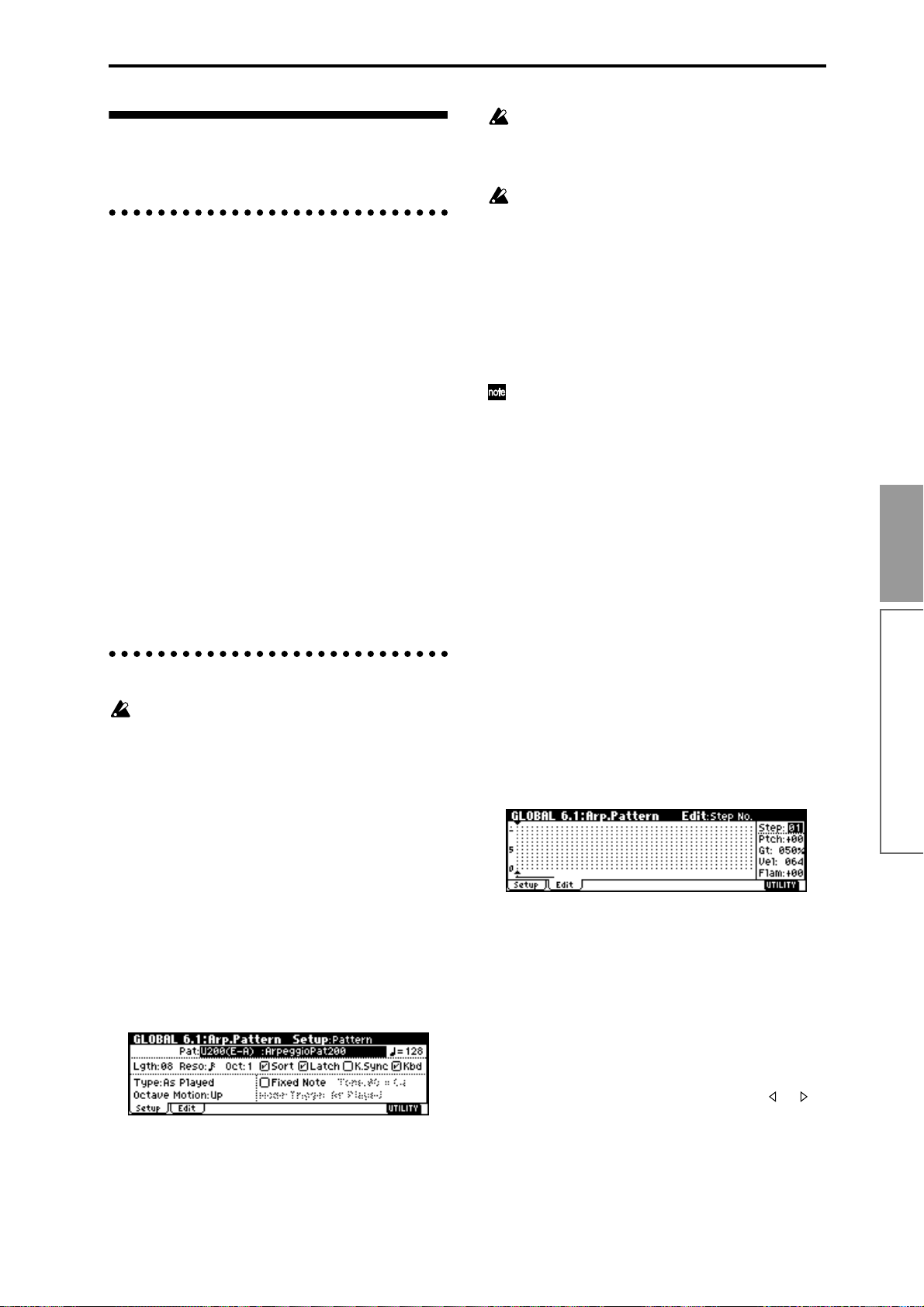
Creating an user arpeggio pattern
About user arpeggio patterns
The patterns that can be selected on the TRITONRack’s arpeggiator are called “arpeggio patterns.”
There are two types of arpeggio patterns: preset arpeggio patterns and user arpeggio patterns.
Preset arpeggio patterns: There are five patterns; UP,
DOWN, ALT1, ALT2, and RANDOM.
The operation of these patterns is fixed, and cannot be
edited.
User arpeggio patterns: There are 328 patterns U000(I–
A/B)–U327(E–H)
Which can develop chords or phrases in a wide variety
of ways, based on the pitches that you play on the keyboard connected MIDI instrument or the timing at
which you play them.
In GLOBAL 6.1: Arp.Pattern you can modify these user
arpeggio patterns, or create a new user arpeggio pattern from an initialized condition. Edited user arpeggio
patterns can be written to internal memory areas
U000(I–A/B)–U327(E–H). In Disk mode, they can also
be saved on external media such as a floppy disk.
(☞p.40)
Editing a user arpeggio pattern
When you wish to edit an user arpeggio pattern,
first turn off memory protect by unchecking the
Memory Protect “Arp. UsrPat” check box in the
Preference page of GLOBAL 1.1: System.
If you move here from Program mode, your editing
will apply to the arpeggio pattern specified for the
selected program.
1 In Program mode, select a program for which the
arpeggio pattern you wish to edit is selected, or a
program that you wish to use as a basis for editing
the arpeggio pattern.
2 Press the [ARP ON/OFF] key to turn on the arpeg-
giator (the LED will light).
Even if you moved to Global mode from a program
in which the arpeggiator was turned off, you can
use the [ARP ON/OFF] key to turn it on.
3 Select the GLOBAL 6.1: Arp.Pattern, Setup page.
4 In “Pattern,” select the arpeggio pattern that you
wish to edit.
For this example, select an empty user arpeggio pattern.
If a blank pattern is selected, playing the keyboard
will not start an arpeggio. Although preset arpeggio patterns P000–P004 can be selected, they cannot be edited.
When you edit a user arpeggio pattern, the
changes will have an effect anytime that this pattern is used in Program, Combination, or Multi.
5 In “Lgth (Length),” specify the length of the pat-
tern.
After the pattern has played for the length specified
here at the note interval specified by “Reso,” it will
return to the beginning. This setting can also be
changed during or after editing. For this example,
set it to 8.
For the preload arpeggio patterns U000(I–A/B)–
U199(I–A/B), simply changing the “Lgth” can significantly change the character of the pattern. Try
changing the length and listening to the result.
6 Make settings for the “ (Tempo),” “Reso (Resolu-
tion),” “Oct (Octave),” “Sort,” “Latch,” “K.Sync
(Key Sync.),” and “Kbd (Keyboard)” parameters.
These are program parameters, but can be set from
here as well.
If after moving here from Program mode, you modify these parameters and wish to keep your changes,
return to Program mode and write the program.
These parameters are not saved by “Write Arpeggio
Pattern.”
For this example, make the settings shown in the
illustration 3.
7 The “Type (Arpeggio Type),” “Octave Motion,”
and “Fixed Note” parameters specify how the
arpeggio will be developed.
These settings can be changed during or after editing (
☞PG p.120).
8 Select the Edit page.
A pattern consists of Steps and Tones.
• Step: A user arpeggio pattern can have a
maximum of 48 steps. The arpeggiator will play
from the first step, at intervals of the note value
specified by “Reso (Resolution).” The vertical
lines of the grid shown in the center of the LCD
screen indicate the steps.
Use “Step (Step No.)” to select the step. For each
step, specify “Ptch (Pitch Offset),” “Gt (Gate),”
“Vel (Velocity)” and “Flam.”
To change Step, you can either use the [ ], [ ]
keys or select “Step (Step No.)” and use the
[VALUE] dial or the [INC], [DEC] keys.
Basic functions
Arpeggiator settings
89
Page 96

• Tone: At each step, a chord consisting of up to
12 tones (Tone No. 00–11) can be sounded.
To input tones, select “Step (Step No.)” and then
use numeric keys [0]–[9], [–], and [./HOLD] to
input tones. The “Tone No.” corresponds to the
[0]–[9], [–], and [./HOLD] keys as shown below.
Each time you press a [0]–[9], [–], or [./HOLD]
key, the corresponding tone will be turned on/
off. The horizontal lines of the grid shown in the
center of the LCD screen indicate the tones.
Tone00–09: [0]–[9] keys
Tone10: [–] key
Tone11: [./HOLD] key
Tone No.
4
3
2
1
0
01 05 Step No.
Lgth(Length)
Creating an example pattern
“Gt (Gate)”: Specify the length of the arpeggio note
for each step. With a setting of LGT, the note will
continue sounding either until the next note of the
same tone or until the end of the pattern. With a setting of Off, the note will not sound.
“Vel (Velocity)”: Specify the strength of the note.
With a setting of Key, the note will sound at the
strength with which it was actually played.
The “Gt (Gate)” and “Vel (Velocity)” settings you
make here will be valid if the “Gt (Gate)” and “Vel
(Velocity)” parameters (PROG 6.1: Ed–Arp.,
Arpeg. Setup page) of the program selected in Program mode are set to Step. If these parameters
have a setting other than Step, the “Gt (Gate)” and
“Vel (Velocity)” that were specified for each individual step will be ignored, and all notes of the
arpeggio will sound according to the settings in
PROG 6.1: Ed-Arp. Be sure to verify the settings of
the program.
Before you set “Gt (Gate),” move the REALTIME
CONTROLS C-mode [ARP-GATE] knob to the
center position (12 o’clock).
Before you set “Vel (Velocity),” move the REALTIME CONTROLS C-mode [ARP-VELOCITY]
knob to the center position (12 o’clock).
1 Set “Step (Step No.)” to 01, and press the [0] key.
2 Set “Step (Step No.)” to 02, and press the [1] key.
3 Set “Step (Step No.)” to 03, and press the [2] key.
4 Set “Step (Step No.)” to 04, and press the [1] key.
5 Set “Step (Step No.)” to 05, and press the [3] key.
6 Set “Step (Step No.)” to 06, and press the [1] key.
7 Set “Step (Step No.)” to 07, and press the [2] key.
8 Set “Step (Step No.)” to 08, and press the [1] key.
9 When you play the keyboard as shown in the illus-
tration, the arpeggiator will begin playing.
Tone 0 corresponds to the pitch of the lowest key of
chord you play on the keyboard. (If “Sort” is
unchecked, it will correspond to the pitch of the first
note you play.)
0 For steps 01–08, make settings for “Ptch (Pitch Off-
set),” “Gt (Gate),” “Vel (Velocity),” and “Flam.”
“Ptch (Pitch Offset)”: This offsets the pitch of the
arpeggio note in semitones up or down. You can
input the same tone for each step, and change the
“Ptch (Pitch Offset)” value for each to create a melody using a single tone. (
☞“Melody pattern”)
A To change the user arpeggio pattern name, use the
Utility “Rename Arpeggio Pattern” (☞p.38).
B If you wish to save the edited user arpeggio pat-
tern to internal memory, be sure to Write the user
arpeggio pattern (☞p.39).
If you turn off the power without writing, the edited
contents will be lost.
C If you wish to save the state of the program at the
same time, return to Program mode and write the
program (☞p.37).
Other examples of creating a user arpeggio pattern
Melody pattern
1 Set “Step (Step No.)” to 01, and press the [0] key.
Set “Ptch (Pitch Offset)” to +00.
2 Set “Step (Step No.)” to 02, and press the [0] key.
Set “Ptch (Pitch Offset)” to +10.
90
Page 97

3 Set “Step (Step No.)” to 03, and press the [0] key.
Set “Ptch (Pitch Offset)” to +00.
4 Set “Step (Step No.)” to 04, and press the [0] key.
Set “Ptch (Pitch Offset)” to +00.
5 Set “Step (Step No.)” to 05, and press the [0] key.
Set “Ptch (Pitch Offset)” to +12.
6 For “Step (Step No.)” 06, do not enter a tone.
7 Set “Step (Step No.)” to 07, and press the [0] key.
Set “Ptch (Pitch Offset)” to +00.
8 Set “Step (Step No.)” to 08, and press the [0] key.
Set “Ptch (Pitch Offset)” to –02.
Chordal pattern
Drum pattern
You can use the arpeggiator to play a rhythm pattern
by using “Fixed Note” with a drum program.
1 Select a drum kit program.
For this example, select preset program I-A036:
Standard Kit.
2 Select the GLOBAL 6.1: Arp.Pattern, Setup page,
and set the parameters.
Check “Fixed Note.” If this is checked, tones will
always sound at the specified pitch.
If you set “Mode (Fixed Note Mode)” to Trigger All
Tones, playing a single note will cause all Tones to
sound.
If you set “Mode (Fixed Note Mode)” to Trigger As
Played, the notes you play will determine how
Tones are sounded.
1 Set “Step (Step No.)” to 01, and press the [0] key.
Set “Gt (Gate)” to LGT.
2 For “Step (Step No.)” 02, do not enter a tone.
3 Set “Step (Step No.)” to 03, and press the [1], [2],
[3], [4] keys.
4 Set “Step (Step No.)” to 04, and press the [1], [2],
[3], [4] keys.
5 For “Step (Step No.)” 05, do not enter a tone.
6 Set “Step (Step No.)” to 06, and press the [1], [2],
[3], [4] keys.
Set “Gt (Gate)” to LGT.
7 For “Step (Step No.)” 07, do not enter a tone.
8 Set “Step (Step No.)” to 08, and press the [1], [2],
[3], [4] keys.
To simulate the timing nuances of a strummed
guitar chord, select “Flam.” In Program mode,
select an acoustic guitar program, and choose the
user arpeggio pattern that you created here. In the
Setup page of PROG 6.1: Ed-Arpeg., set “Gate” to
Step.
Then return to the GLOBAL 6.1: Arp.Pattern, Edit
page. For odd-numbered steps, set “Flam” to a
positive (+) value. For even-numbered steps, set
“Flam” to a negative (–) value.
Fixed Note
Mode(Fixed Note Mode)
Tone No. Fixed Note No.
If “Fixed Note” is checked, you will be able to set
“Tone No.” and “Fixed Note No.”
Select “Tone No.,” and then set “Fixed Note No.” to
specify the note number that the tone will sound.
Here, set “Tone No.” and “Fixed Note No.” as follows.
Tone No. Fixed Note No.
00 C2 (kick)
01 F2 (snare)
02 F#3 (closed hi-hat)
03 A#3 (open hi-hat)
The drumsamples that correspond to each note
number will differ depending on the drum kit. You
will find it convenient to audition the drum sounds
from the keyboard of a connected MIDI instrument,
and then input the “Fixed Note No.” by holding
down the [ENTER] key and playing the desired
note.
3 Select the Edit page.
Each Tone in the display will be shown as a small
circle.
For each horizontal line (Tone) in the display, you
will specify a drumsample (note number) of the
drum kit.
Next we will input a rhythm pattern.
Basic functions
Arpeggiator settings
91
Page 98

4 Input the kick (Tone00).
Set “Step (Step No.)” to 01, and press the [0] key.
Then set “Step (Step No.)” to 05, and press the [0]
key.
5 Input the snare (Tone01).
Set “Step (Step No.)” to 03, and press the [1] key.
Then set “Step (Step No.)” to 07, and press the [1]
key.
6 Input the closed hi-hat (Tone02).
Set “Step (Step No.)” to 01, 02, 03, 05, 06, and 07,
and press the [2] key for each.
7 Input the open hi-hat (Tone03).
Set “Step (Step No.)” to 04, and press the [3] key.
Then set “Step (Step No.)” to 08, and press the [3]
key.
If “Mode (Fixed Note Mode)” is set to Trigger All
Tones, playing a single note on the keyboard will
cause the rhythm pattern to play.
If “Mode (Fixed Note Mode)” is set to Trigger As
Played, playing a single note on the keyboard will
cause only the kick (Tone00) to play. Playing two
notes on the keyboard will cause only the kick
(Tone00) and snare (Tone01) to play. In this way, the
number of keys that you play will be played by the
same number of tones.
8 Set the parameters for each step.
Use “Vel (Velocity)” etc. to add accents to the
rhythm pattern.
The “Gt (Gate)” and “Vel (Velocity)” settings you
make here will be valid if the “Gate” and “Velocity” parameters (PROG 6.1: Ed–Arp., Arpeg. Setup
page) of the program selected in Program mode
are set to Step.
If these parameters have a setting other than Step,
the “Gt (Gate)” and “Vel (Velocity)” that were
specified for each individual step will be ignored,
and all notes of the arpeggio will sound according
to the specified gate and velocity.
Before you set “Gate,” move the REALTIME CONTROLS C-mode [ARP-GATE] knob to the center
position (12 o’clock).
Before you set “Velocity,” move the REALTIME
CONTROLS C-mode [ARP-VELOCITY] knob to
the center position (12 o’clock).
Dual arpeggiator editing
Here we will use a combination as an example in our
explanation.
The same procedure applies when editing an arpeggio
pattern in Multi mode.
If you have moved from Combination mode, the arpeggio pattern selected by the combination will be affected
by your editing.
1 In Combination mode, select a combination that
uses the arpeggio pattern you wish to edit.
For this example, select a combination to which
arpeggiators A and B is assigned.
2 Press the [ARP ON/OFF] key to turn on the arpeg-
giator (the LED will light).
Even if the arpeggiator had been turned off when
you moved here, you can use the [ARP ON/OFF]
key to turn it on. However, if “Arpeggiator Run” A
or B are not checked, and if no timbres have been
assigned in “Assign,” then the arpeggiator will not
operate.
3 Select the GLOBAL 6.1: Arp.Pattern, Setup page.
4 If you moved here from Combination mode, use
the “Arp (Arpeggio Select)” A and B to select the
arpeggiator that you wish to edit.
If this is A, your editing will apply to the parameters
and user arpeggio pattern of arpeggiator A.
If this is B, your editing will apply to the parameters
and user arpeggio pattern of arpeggiator B.
5 Switch between arpeggiators A and B, and edit
their respective user arpeggio patterns.
If you wish to stop one of the arpeggiators, return to
Combination mode, and in COMBI 1.1: Play, select
the Arp. A or the Arp. B page and uncheck the
“Arpeggiator Run” check box.
6 To modify the name of a user arpeggio pattern, use
the Utility “Rename Arpeggio Pattern” (☞p.38).
7 If you wish to save the edited user arpeggio pat-
tern in internal memory, you must write the user
arpeggio pattern.
In this case, both user arpeggio patterns will be written simultaneously. If you turn off the power without writing, the edited contents will be lost (☞p.39).
8 If you wish to save the state of the combination at
the same time, return to Combination mode and
write the combination (☞p.37).
When you edit a user arpeggio pattern, pay attention to the MIDI transmission channel of the connected MIDI instrument, the global MIDI channel,
the channel of each track, and the arpeggiator
assignments, and make sure that the arpeggiator
you are hearing is playing the pattern that you
wish to edit.
If you moved here from Sampling mode, the
arpeggiator will not turn on. Nor will it be possible
to edit arpeggio patterns.
92
Page 99

About arpeggiator synchronization
The note timing of the arpeggiator will depend on the
setting of its “Key Sync.” check box.
If this is checked, the arpeggiator will begin operating
at the moment that you play the first note-on after having released all notes on the connected MIDI instrument.
If this is unchecked, the arpeggiator will synchronize
to the timing of the internal/external MIDI clock.
The following paragraphs explain how synchronization occurs when the “Key Sync.” check box is
unchecked. (Synchronization for Pattern Start and
MIDI realtime command “Start” is an exception to
this.)
Synchronizing arpeggiators A and B
In Combination, or Multi modes, the two arpeggiators
can be operated simultaneously.
At this time if one arpeggiator is running and the other
arpeggiator (whose “Key Sync.” is not checked) is
started, the second arpeggiator will synchronize to the
“ (Tempo) ” based on the timing of the first arpeggiator.
Synchronization with an external
sequencer in Program, Combination,
or Multi mode
When “ (Tempo) ” is set to EXT (GLOBAL 2.1: MIDI,
“MIDI Clock”), the arpeggiator will synchronize to
MIDI Clock or Start messages etc. received from an
external MIDI sequencer etc. connected via a MIDI
cable.
Synchronization with external MIDI clock
• The arpeggiator will synchronize to the
“ (Tempo)” based on the timing of the external
MIDI clock.
Synchronization to the MIDI realtime command
“Start”
• If the MIDI realtime command “Start” is received
while the arpeggiator is running, the arpeggiator
will be reset to the beginning of the arpeggio
pattern. (This is not affected by the “Key Sync.”
setting.)
Basic functions
If “Key Sync.” is checked, arpeggiators A and B
will operate with independent timing.
Synchronization with pattern playback in Multi mode, synchronization
with RPPR pattern playback in Multi
mode
Synchronization with pattern playback
• If you start pattern playback while the arpeggiator
is running, the arpeggiator will be reset to the
beginning of the arpeggio pattern. (This is not
affected by the “Key Sync.” setting.)
• If “Key Sync.” is not checked for pattern recording,
you can turn on the [ARP ON/OFF] key and play
the keyboard of a connected MIDI instrument
during the recording pre-count so that the arpeggio
pattern will start from the beginning at the instant
that recording begins, and will be recorded.
Synchronization with RPPR pattern playback
• If you trigger the arpeggiator while a pattern is
playing, the arpeggiator will synchronize to the
beat of the pattern playback.
• If you want pattern playback to synchronize to the
already-running arpeggiator, set “Sync” (MULTI
5.1: RPPR, RPPR Setup page) to ARP (SEQ).
Pattern playback will synchronize to the
“ (Tempo)” timing of the arpeggiator.
Arpeggiator settings
93
Page 100

Effects settings
The effect section of the TRITON-Rack provides five
insert effects, two master effects, one master EQ (ste-
reo 3-band EQ), and a mixer that contr ols the routing of
these components.
You can choose from 102 types of full-digital effects for
each insert effect, and from 89 types for each master
effect. The effects are categorized as follows.
Categories of the 102 effect types
001–015 Filter and dynamics effects, such as EQ and com-
pressor
016–031 Pitch and phase modulation effects, such as chorus
and phaser
032–040 Other modulation and pitch-shift effects such as
rotary speaker and pitch shifter
041–051 Early reflection and delay effects
052–057 Reverb effects
058–089 Mono and mono-chain effects in which two mono
effects are connected in series
090–102 Double-size effects
Effects 000–089 can be selected for IFX1, 2, 3, 4, 5,
or MFX 1 or 2. Effects 090–102 are double-size
effects, and will use twice the processing area of
other effects. They can be selected for IFX2, IFX3 or
IFX4.
Effects in each mode
In Program mode, insert effects can be used as part of
the sound-creating process, in the same way that the
output sound of the oscillator (OSC) is processed by
the filter and amp to create the final sound. Then the
master effects can be used to apply spatial-type effects
such as reverb. The stereo 3-band master EQ located
immediately before the OUTPUT (MAIN) L/MONO
and R outputs is used to make final adjustments in
tone. These settings can be made independently for
each program.
Master Effect 1,2
Insert Effect 1-5
Filter
Amplifier
Oscillator
In Combination mode, and Multi mode , insert effects
can be used to help create the sound of each timbre/
track. The master effects are used to apply overall spatial processing, and the master EQ is used to make
overall adjustments in tone.
These settings are made in Combination mode independently for each combination, and in Multi mode for
each multi the entire mode.
Master Effect 1,2
Timbre 1 / Track 1
Timbre 2 / Track 2
Timbre 8 / Track 16
Insert Effect 1-5
ReturnSend
ReturnSend
Master EQ
Master EQ
OUTPUT
L/MONO, R
OUTPUT
L/MONO, R
In Sampling mode, the sound of an external source
that is input from AUDIO INPUT 1 and 2 can be processed by the insert effects as the sound is sampled.
Sampling mode settings are made by the “Input 1” and
“Input 2” parameters of the SMPL 1.1: Recording,
Input/Pref page. The settings here are valid only
within Sampling mode.
AUDIO INPUT 1, 2
Insert Effect 1-5
Sample
Recording
The external input from AUDIO INPUT 1 and 2 can be
used outside of Sampling mode. In Program, Combination, and Multi modes, the external input sound can be
processed by the insert effects, master effects, and
master EQ.
This means that you can use the TRITON-Rack as a 2in/6-out effect processor. When 093: Vocoder is
selected, the TRITON-Rack can be used as a vocoder
effect processor in which its internal sounds are controlled by an external mic input.
ReturnSend
Master EQ
OUTPUT
L/MONO, R
Oscillator
AUDIO INPUT 1, 2
Filter
Amplifier
Master Effect 1,2
Insert Effect 1-5
94
 Loading...