

Page 1
2E
Page 2
Thank you for purchasing the Korg TRITON Extreme music workstation/sampler .
To ensure trouble-free enjoyment, please read this manual carefully and use the instrument
as directed.
About this manual
The owner’s manuals and how to use
them
The TRITON Extreme come with the following
owner’s manuals.
• Quick Start
• Operation Guide
• Parameter Guide
• Voice Name List
Quick Start
Read this manual first. This is an introductory guide
that will get you started using the TRITON Extreme. It
explains how to play back the demo songs, select
sounds, use convenient performance functions, and
perform simple editing. It also gives examples of using
sampling and the sequencer.
Operation Guide
This manual describes each part of the TRITON
Extreme and what it does, how to make connections,
basic operation, and a summary of each mode. It also
explains, for each mode, the basics of editing your
sounds, recording on the sequencer , and sampling. The
arpeggiator, effects, and MIDI are also explained.
This manual also contains other information such as a
troubleshooting guide and specifications.
Parameter Guide
The Parameter Guide contains explanations and other
information regarding the operations of the parameters and settings on the TRITON Extreme. The explanations are organized by mode, and page.
Explanations and other information on the effects and
their parameters are also provided for each effect.
Refer to this guide when an unfamiliar parameter
appears in the display, or when you need to know
more about a particular function.
Voice Name List
This lists the multisamples and drumsamples that are
built into the TRITON Extreme, and the factory preset
combinations, programs, drum kits, and user arpeggio
patterns.
Refer to these lists when you wish to know more about
the preloaded sounds.
Conventions in this manual
References to the TRITON Extreme
The TRITON Extreme is available in 88-key, 76-key and
61-key models, but all three models are referred to
without distinction in this manual as “the TRITON
Extreme.” Illustrations of the front and rear panels in
this manual show the 61-key model, but the illustrations apply equally to the 88-key and 76-key models.
Abbreviations for the manuals QS, OG, PG, VNL, EM
The names of the manuals are abbreviated as follows.
QS:
Quick Start
OG:
Operation Guide
PG:
Parameter Guide
VNL:
Voice Name List
EM:
EXB-MOSS Owner’s Manual
EXB-MOSS option)
Keys and knobs [ ]
References to the keys, dials, and knobs on the TRITON Extreme’s panel are enclosed in square brackets
[ ]. References to buttons or tabs indicate objects in
the LCD display screen.
Parameters in the LCD display screen “ ”
Parameters displayed in the LCD screen are enclosed
in double quotation marks “ ”.
Boldface type
Parameter values are printed in boldface type.
Content that is of particular importance is also printed
in boldface type.
Procedure steps
Steps in a procedure are listed as
☞
p.
■
These indicate pages or parameter numbers to which
you can refer.
Symbols
These symbols respectively indicate cautions, advice,
and MIDI-related explanations.
Example screen displays
The values of the parameters shown in the example
screens of this manual are only for explanatory purposes, and may not necessary match the values that
appear in the LCD screen of your instrument.
1
2
3
, ,
...
(included with the
1
2
3
...
MIDI-related explanations
CC# is an abbreviation for Control Change Number.
In explanations of MIDI messages, numbers in square
brackets [ ] always indicate hexadecimal numbers.
ii
Page 3

Table of Contents
About this manual.......................................ii
Introduction................................................ 1
Main features......................................................................1
Front and rear panel.......................................................... 3
Names and functions of objects in the LCD screen......8
Overview of the TRITON Extreme’s modes................10
About polyphony ............................................................12
Basic operation.................................................................13
Setup....................................................... 15
Connections......................................................................15
Turning the power on/off.............................................. 18
Playing and editing programs
(Program Mode)....................................... 19
Program structure............................................................19
Playing a program P0: Play............................................ 20
Program editing...............................................................23
Oscillator settings P1: Edit-Basic...................................24
Pitch settings P2: Edit-Pitch ...........................................26
Filter settings P3: Edit-Filter...........................................27
Amplifier settings P4: Edit-Amp...................................28
LFO settings P5: Edit-Common LFO............................29
Arpeggiator settings P7: Edit-Arpeggiator..................30
Insert Effect settings P8: Edit-Insert Effect................... 30
Master Effect and Valve Force settings
P9: Edit-Master Effect.................................................. 30
More about Alternate Modulation................................30
Auto Song Setup function.............................................. 30
Playing and editing combinations
(Combination Mode)................................. 31
Combination structure....................................................31
Playing a combination P0: Play.....................................32
Combination editing ....................................................... 33
Timbre 1–8 program, pan and volume
P1: Edit-Program/Mixer.............................................34
Settings for status, MIDI channel, and pitch parameters
P2: Edit-Trk Param ......................................................35
MIDI filter settings P3: Edit-MIDI Filter ......................36
Layer, split, and velocity switch settings/Controller
settings P4: Edit-Zone/Ctrl........................................36
Arpeggiator settings P7: Edit-Arp. ...............................37
Insert Effect settings P8: Edit-Insert FX........................37
Master Effect and Valve Force settings
P9: Edit-Master FX.......................................................37
Auto Song Setup function.............................................. 38
Producing songs (Sequencer mode) ...........39
Features of the sequencer............................................... 39
The structure of Sequencer mode................................. 40
Preparations for recording.............................................41
Recording methods......................................................... 43
Song editing methods..................................................... 50
Creating and playing a Cue List ................................... 53
Creating and recording RPPR (Realtime Pattern Play/
Record).......................................................................... 55
Recording the sound of a combination or program...58
Caution and other functions in Sequencer mode....... 59
Sampling (Open Sampling System)............61
Features of sampling on the TRITON Extreme .......... 61
How Sampling mode is organized............................... 62
Samples and Multisamples............................................ 63
Preparations for sampling ............................................. 64
Sampling and editing in Sampling mode.................... 68
Sampling in Program, Combination, or Sequencer
modes............................................................................ 80
SMF (Standard MIDI File) playback............ 85
How Song Play mode is structured..............................85
Playing SMF data ............................................................ 86
Playback using the Jukebox function........................... 87
Playing along with SMF data ........................................ 88
Settings for the entire TRITON Extreme
(Global mode) ..........................................89
How Global mode is structured.................................... 89
Basic Setup P0: Basic Setup............................................89
MIDI-related settings P1: MIDI.....................................90
Pedal and other controller settings P2: Controller..... 90
Creating original scales P3: User Scale......................... 91
Drum kit settings P5: Drum Kit .................................... 92
Arpeggiator settings P7: Edit-Arpeggiator.................. 94
Effect and Valve Force settings ................103
Routing settings and effect settings............................ 104
Valve Force settings...................................................... 109
Loading and saving data, creating audio CDs,
and editing Wave files
(Media mode, etc.)..................................113
Types of data that can be saved .................................. 113
Writing to internal memory......................................... 114
The pages of Media mode............................................ 116
Saving on media Media, Save ..................................... 117
File copying, deleting, and formatting
(Media, Utility) .......................................................... 119
Loading data Media, Load........................................... 121
iii
Page 4

Use sampled Wave files to create an audio CD and play
it: Media, Make Audio CD, Play Audio CD.......... 123
Editing a Wave file: Media, Edit WAVE....................125
Viewing information about media: Media,
Media Info...................................................................125
Handling CompactFlash and Microdrive media...... 125
Restoring the factory settings...................127
Restoring the factory settings...................................... 127
Loading the EXB-MOSS data....................................... 128
Other functions.......................................129
Setting the function of [SW1] and [SW2] ...................129
Setting the B-mode functions of REALTIME
CONTROLS [1]–[4].................................................... 129
Adjusting the contrast (brightness) of the
LCD screen ................................................................. 129
Using tap tempo control............................................... 130
Shortcuts......................................................................... 130
Appendices.............................................131
Troubleshooting ............................................................ 131
Media that can be used with the TRITON Extreme. 137
Specifications and options ........................................... 138
Options............................................................................ 139
System requirements for computer connection........ 139
MIDI implementation chart......................................... 140
Index................................................................................ 141
iv
Page 5

Introduction
Main features
The TRITON Extreme is a music workstation/sampler
that features the
as its tone generator.
It provides high-quality preset multisamples/programs/
combinations together with a broad range of integrated
features such as an effect section, 16-track MIDI
sequencer, sampling, dual polyphonic arpeggiators,
RPPR, four-channel audio input/six-channel audio out-
put, and song play functionality.
You can modify the sound in realtime by using a wide
range of performance controllers such as the joystick, rib-
bon controller, REALTIME CONTROLS and ARPEGGIA-
TOR knobs, and pedals that you connect.
You can also expand the TRITON Extreme’s capabilities
by installing the MOSS modeling synthesizer or by add-
ing more sample memory (RAM).
The TRITON Extreme music workstation is a powerful
tool for music production or live performance.
HI (Hyper Integrated) synthesis system
The HI (Hyper Integrated) synthesis system is a PCM tone
generator system with full digital signal processing that
guarantees pristine sound, and featuring enormous flexi-
bility in musical expression, modulation, and effect rout-
ing.
* The TRITON Extreme contains an analog vacuum tube
circuit (Valve Force). When you use Valve Force, the
signal is converted into analog form at that point.
Tone generator section:
• 160 Mbytes of preset PCM ROM contains 962
multisamples and 1,175 drumsamples.
• The TRITON Extreme is shipped with 16 Mbytes of
RAM (you can expand this to a maximum of 96
Mbytes), letting you use samples or multisamples you
sampled/resampled or loaded in Media mode.
• The sampling frequency is 48 kHz, and the maximum
polyphony is 60 voices (a maximum of 120 voices can
be used depending on the PCM sounds you use).
Filter/synthesis section:
• Either a 24 dB/oct Resonant Low Pass or a 12 dB/oct
Low Pass & High Pass type filter can be used. A wide
variety of filter effects can be achieved, from active
sounds with aggressive resonance to subtle tones
using a high pass filter.
•A broad range of editing parameters gives you precise
control over every aspect of the sound.
Effect section:
• Five insert effects (stereo-in/stereo-out), two master
effects (mono-in/stereo-out), and a three-band master
EQ (stereo-in/stereo-out) can all be used
simultaneously. You can select and edit any of 102
types of effect algorithms.
• The effect routing is highly flexible. Effects can be
routed freely to the individual inputs and outputs.
HI (Hyper Integrated) synthesis system
Alternate Modulation and
Effect Dynamic Modulation:
• The synthesis section (filter etc.) provides Alternate
Modulation capabilities, and the effect section
provides Effect Dynamic Modulation. This allows you
to freely apply modulation to parameters that affect
the pitch, filter, amp, EG, LFO, and effects etc.
• LFO, delay time and other effect parameters can be
synchronized to an external MIDI clock. You can also
synchronize sounds and effects to the tempo of the
internal sequencer or the arpeggiator.
Valve Force circuit:
• This section includes an analog low-frequency boost
circuit plus a vacuum tube amp that uses a 12AU7
(ECC82) vacuum tube. One vacuum tube is used to
support stereo-in/stereo-out. Proprietary Korg
technology is used to generate warm and powerful
sound with the rich overtones and smooth distortion
typical of vacuum tubes, while retaining clarity and
definition.
Programs and combinations
Programs:
• In addition to 1,536 user programs, 256 programs (and
9 drum kits) for GM2 compatibility are provided as
ROM presets.
You can use a rich array of editing parameters, effects,
Valve Force, and the arpeggiator to modify the 1,536
user programs and create your own original programs.
When the TRITON Extreme is shipped from the factory, user memory contains 1,344 high-quality programs that cover a wide range of needs. When the
EXB-MOSS option is installed, 128 programs for use
with the Korg MOSS tone generator will also be available.
• The TRITON Extreme provides 144 user drum kits as
well as 9 ROM drum kits compatible with GM2. The
factory settings contain 50 preloaded drum kits that
cover a wide range of musical styles.
You can create your own drum kits by assigning each
key to any one of the 1,175 drum samples or to an original sample that you sampled or loaded in from media.
For the sound assigned to each key , you can make filter
and amp settings, and even route the sound to effects
or individual audio outputs.
• You can easily create programs using multisamples or
samples that you yourself sampled/resampled or
loaded in Media mode. You can then use these
programs in combinations and songs. You can also use
samples as drum instruments in a drum kit.
Combinations:
• The TRITON Extreme provides 1,536 user
combinations. Each combination can combine up to
eight layered/split/velocity-switched programs,
together with settings for effects, the Valve Force
circuit, and the two arpeggiators. Combinations let
you create very complex sounds that could not be
produced by a program alone. You can also use an
external sound module as part of a combination.
When the TRITON Extreme is shipped, user memory
contains a versatile range of 1,280 preloaded
combinations.
Introduction
Program
Combination
SequencerSamplingSong PlayGlobalEffectMedia, etcPresetOther
1
Page 6

Sequencer
A sophisticated 16-track MIDI sequencer is built in.
• The TRITON Extreme combines dual arpeggiators,
RPPR, time slice, in-track sampling, and many other
functions, giving you an integrated music production
environment with even more potential than an
external sequencer would provide. MIDI exclusive
message recording/playback is also supported.
• The Cue List function lets you play up to 99 songs in
the order you specify. For example you could create
separate songs for the intro, melody A, melody B, and
the break, etc., and easily try out different song
structures using the same material. You can also
specify the number of times that each song will repeat.
Songs can also be played back consecutively in jukebox
style.
•A completed song can be resampled as a Wave file
and burned to a CD-R/RW drive (sold separately)
connected to the USB A connector to create an original
audio CD.
Sampling
The TRITON Extreme features our Open Sampling System that allows sampling and resampling to be performed
not only in Sampling mode, but also in Program, Combination, or Sequencer modes.
48 kHz 16-bit linear mono/stereo sampling is supported.
Sample memory (RAM) of 16 Mbytes is factory-
•
installed, allowing approximately 2 minutes 54
seconds of mono sampling (or approximately 1 minute
27 seconds of stereo sampling). Sample memory can
be expanded to a maximum of 96 Mbytes, which
allows you to record up to six samples of
approximately 2 minutes 54 seconds each (mono) or
approximately 1 minute 27 seconds each (stereo), for a
total 17 minutes 28 seconds of sampling time.
media (Option) lets you record up to 80 minutes
• The
as a single sample file in either mono or stereo
(monaural: approximately 440 Mbytes, stereo:
approximately 879 Mbytes). This will create a WAVE
file. (In order to play a media sample from the
TRITON Extreme’s keyboard, it must be able to be
loaded into the sampling memory (RAM).)
In order to sample to media on the TRITON Extreme,
you will need to obtain media of the recommended
☞
type (sold separately). (
p.137)
Song Play
In Song Play mode you can play SMF (Standard MIDI
File) data directly from media. You can also play the keyboard along with the SMF playback, and use the arpeggiator in synchronization with the playback tempo of the
SMF. Format 0 and 1 are supported, and you can also use
the Jukebox function to edit the playback order of the
songs.
Dual polyphonic arpeggiator
• Five preset arpeggio patterns (UP, DOWN, ALT1,
ALT2, RANDOM) and 507 user arpeggio patterns are
built-in.
• With the factory settings, these contain a wide variety
of preload user patterns (489).
• In addition to providing conventional arpeggiator
functions, the polyphonic arpeggiator of the TRITON
Extreme can respond to the pitches or timing at which
you play the keyboard, and produce a diverse range of
chords or phrases. This can be used to play a variety of
drum phrases (using the “Fixed Note Mode” that is
ideal for drums), bass phrases, or guitar and keyboard
backing riffs. The arpeggiator is also effective for use
with subtly moving pads, synth sounds, or sound
effects.
• In Combination mode, Sequencer mode, and Song
Play mode, the TRITON Extreme provides dual
arpeggiators that can simultaneously play two
arpeggio patterns. You can apply separate arpeggio
patterns to drum and bass programs, or use keyboard
splits or velocity to switch between arpeggio patterns
for an even more dynamic performance.
RPPR
• The TRITON Extreme features Korg’s RPPR (Realtime
Pattern Play/Recording) function.
In Sequencer mode, this function allows you to assign
preset patterns or user patterns (with a specified playback track) to individual notes of the keyboard, and
playback that pattern in realtime simply by pressing
the assigned note. Numerous preset patterns, including patterns ideal for drum tracks, are built into the
internal memory.
4-channel audio input/
6-channel audio output
• Both analog (2 channel) and digital (2 channel) audio
inputs are standard, allowing you to record stereo
samples.
The analog inputs have a MIC/LINE level select
switch and a level knob, accommodating a wide range
of audio sources from mic level to line level.
The built-in digital input supports 48 kHz S/P DIF format digital audio.
The audio input can be routed through effects and/or
Valve Force. During sampling, you can apply effects or
Valve Force, use the TRITON Extreme as a 4-in/6-out
effect processor, or use a vocoder effect that combines
the audio input with internal sounds.
• Six channels of audio output are provided.
For analog output, you have the L/MONO and R main
stereo output, as well as four independent audio outputs (INDIVIDUAL) 1, 2, 3, and 4. Individual oscillators, drums, timbres/tracks, or the output of an insert
effect can be freely routed to any of these outputs.
For digital output, there’s an S/P DIF connector (two
channels; L/MONO and R) that supports a sampling
frequency of 48 kHz.
TouchView user interface
As its user interface, the TRITON Extreme features the
×
TouchView system with a large 320
touch-panel that lets you perform functions simply by
touching the screen – a revolutionary leap in operability
and practicality.
240 pixel LCD
USB connectors allow connection to a CD-R/
RW drive and computer
The TRITON Extreme provides a USB A connector and a
USB B connector, allowing you to save data on USB storage media (hard disks, removable disks, CD-R/RW
drives).
You can back-up data from media in the CF card slot to
your computer, or edit data on your computer and load it
into the TRITON Extreme.
2
Page 7
Front and rear panel
Front panel
8
16
17
5
4
6
1
2
3
7101118
1. [SW1] key, [SW2] key
These keys are on/off switches, their function can be
assigned in Program, Combination, Sequencer, Song Play,
☞
and Sampling modes. When on, the key will light (
2. Joystick
Various program parameters and effect parameters will
determine what is being controlled by the joystick.
Move the joystick up/down and left/right (+Y, –Y, –X,
☞
☞
p.21).
p.21).
+X) to vary the effect (
3. Ribbon controller
Various program parameters and effect parameters will
determine what is controlled by the ribbon controller.
Slide your finger to the left or right on this ribbon controller to vary the effect (
4. [VOLUME] slider
This adjusts the volume that is output from the AUDIO
OUTPUT (MAIN) L/MONO, R jacks and the headphone
jack.
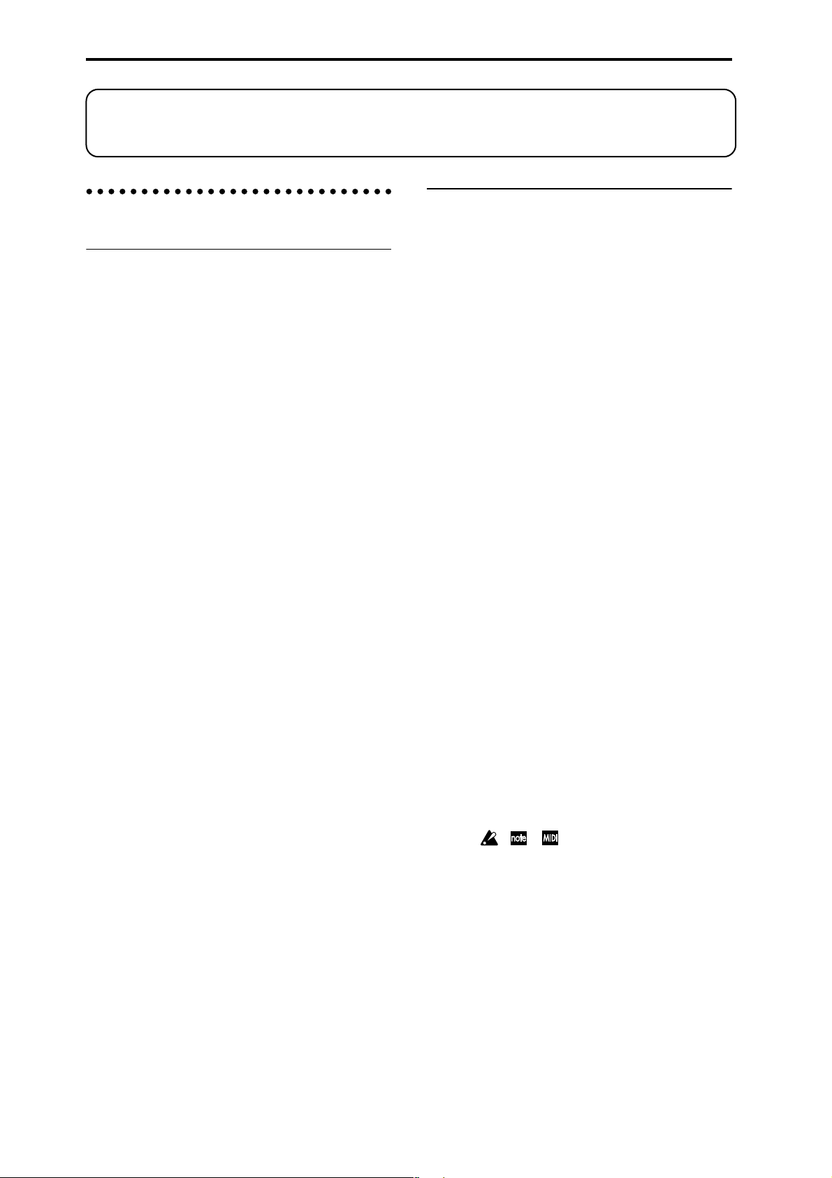
5. REALTIME CONTROLS
p.21).
9
12
13 14 15
Use the [REALTIME CONTROLS] key to select either the
the A mode, B mode or VALVE FORCE functions for the
realtime controllers, and use knobs [1]–[4] to control the
tone, effects, MIDI control changes and Valve Force in
☞
realtime (
[REALTIME CONTROLS] key
This key selects either A, B or Valve Force mode for the
realtime controllers. The selected mode will light.
VALVE FORCE [ON/OFF] key
Switches the Valve Force function on/off. When on, this
key will light.
[1] knob, [2] knob, [3] knob, [4] knob
In A mode , the function of each knob is fixed. [1] is the
low pass filter cutoff frequency, [2] is the filter resonance
level or the cutoff frequency of the high pass filter, [3] is
the filter EG intensity, and [4] is the filter/amp release
time.
B mode , each knob will control the function that was
In
assigned to it in the Program, Combination, Sequencer,
Song Play, or Sampling modes.
The
controls the input level to Valve Force, knob [2] controls
the mix level of the Valve For ce analog ultra-low boost circuit, knob [3] controls input gain to the vacuum tube, and
knob [4] controls the output level from Valve Force.
p.22, QS p.6).
Valve Force functions of the knobs are fixed; knob [1]
Depending on the sound you are using, you may hear
noise if you turn the Valve Force knobs or edit Valve
Force parameters while sound is being produced.
Introduction
Program
Combination
SequencerSamplingSong PlayGlobalEffectMedia, etcPresetOther
3
Page 8
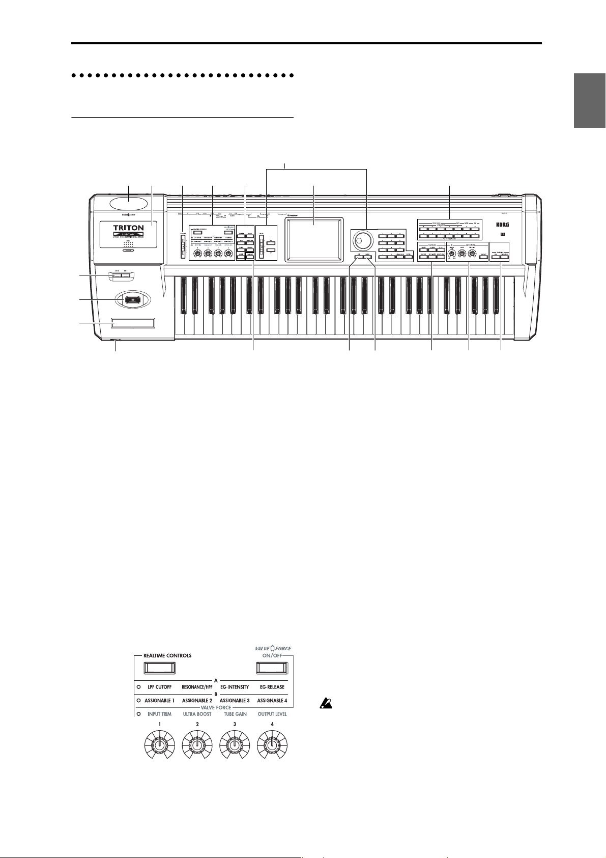
6. Mode keys
Use these keys to enter the desired mode.
When you press a key, the key will light, and you will
☞
enter the mode whose key you pressed (
p.10).
[COMBI] key
Combination mode will be selected.
[PROG] key
Program mode will be selected.
[SEQ] key
Sequencer mode will be selected.
[SAMPLING] key
Sampling mode will be selected.
[S.PLAY] key
Song Play mode will be selected.
[GLOBAL] key
Global mode will be selected.
[MEDIA] key
Media mode will be selected.
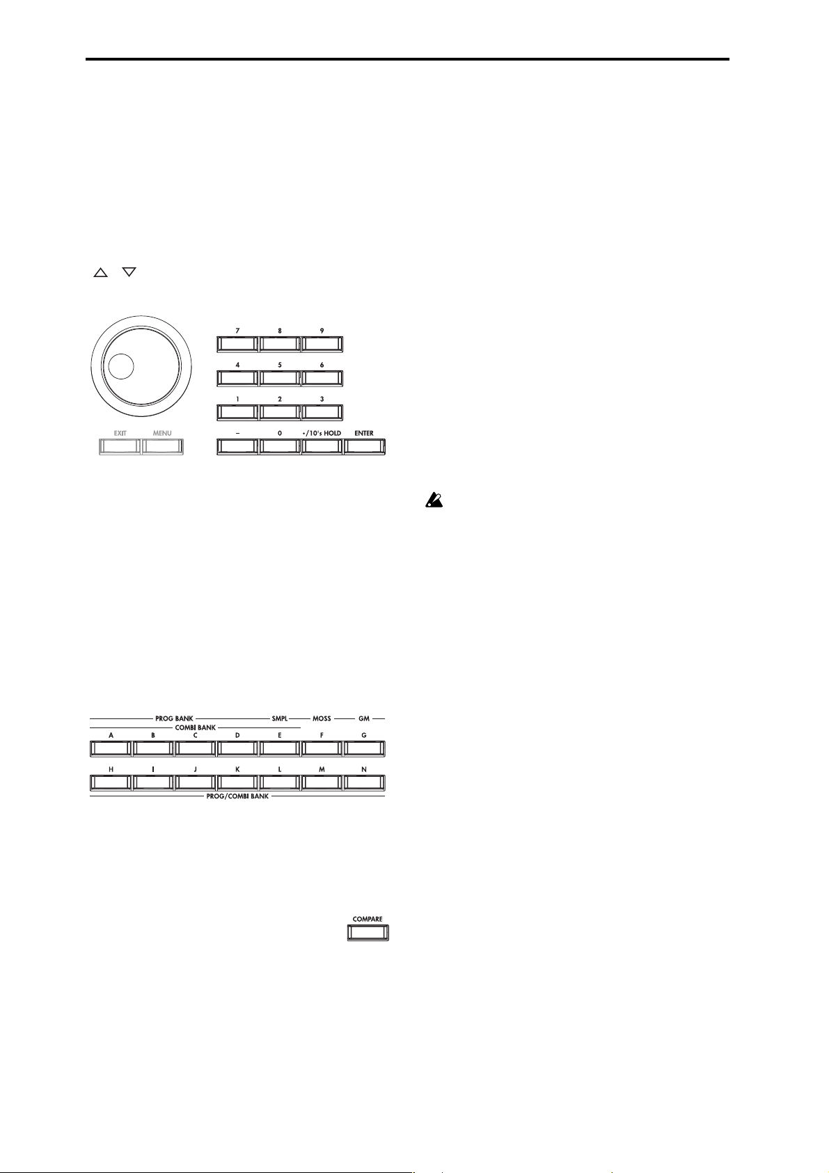
7. [COMPARE] key
Use this key when you wish to compare the sound of the
program or combination that you are currently editing
with the un-edited sound already in memory . You can also
use this key to make “before and after” comparisons
☞
when recording or editing in Sequencer mode (
p.14).
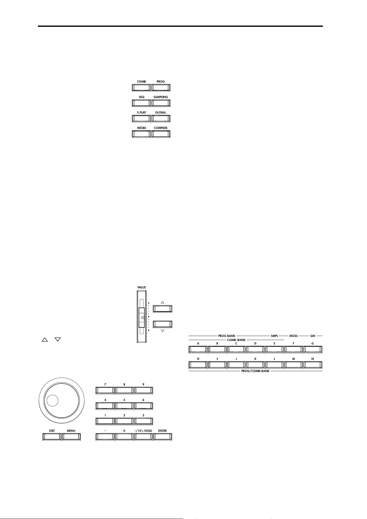
Numeric keys [0] – [9], [ENTER] key, [–] key
[./10’s HOLD] key
Use these keys to numerically input a parameter value.
Use numeric keys [0]–[9], the [–] key, and the [./10’s
HOLD] key to enter the value, and press the [ENTER] key
to confirm it. The [./10’s HOLD] key lets you input a
value with a decimal point. The [–] key inverts the sign
(+/–) of the parameter value.
The [./10’s HOLD] key is also used when you wish to
hold the 10’s place while selecting programs or combinations.
By holding down the [ENTER] key while you press a
numeric key [0]–[9] you can select up to ten page menu
commands from the current page. In Program and Combination modes, you can hold down the [ENTER] key and
press the SEQUENCER [REC/WRITE] key to turn on the
☞
Auto Song Setup function. (
p.58)
9. LCD screen
The TRITON Extreme features our exclusive TouchView
graphic interface, based on a touch-panel LCD screen.
By touching on objects that are shown in the LCD screen,
you can select pages, tabs, and parameters, and set values
☞
p.8).
(
10. [EXIT] key
When in P (page) 1–9 of each mode, pressing the [EXIT]
key will move to P (page) 0 of that mode.
When a dialog box is open, this key will cancel the settings made in the dialog box and close the dialog box (corresponds to the Cancel button). If a popup menu or page
menu is open, pressing [EXIT] will close the menu.
8. VALUE controllers
The following V ALUE controllers ar e used to set the value
☞
of the selected parameter (
p.14).
[VALUE] slider
Use this to modify the value of a parameter. This controller is convenient when
you wish to make large changes in the
value.
This slider can also be used as a modulation source.
[][] keys
These are used to increase or decrease the parameter
value in steps of one. These keys are convenient for making fine parameter adjustments.
[VALUE] dial
Use this dial to modify the value of the parameter.
11. [MENU] key
Use this key to move between pages. When you press the
[MENU] key, a list of the pages in the mode will appear in
the LCD screen. Press the desired page, and you will
move to that page. You can also move to a page by holding down the [MENU] key and pressing the corresponding numeric key [0]–[9] (☞p.9, 13).
12. BANK keys
These keys are used to switch the program/combination
bank.
PROG BANK:
[A], [B], [C], [D], [E] (SMPL), [F] (MOSS), [G] (GM), [H],
[I], [J], [K], [L], [M], [N]
COMBI BANK:
[A], [B], [C], [D], [E], [H], [I], [J], [K], [L], [M], [N]
In Program mode, these keys select the program bank.
In Combination mode, these keys select the combination
bank. When assigning a program to the various timbres in
a combination, then these keys will select the program
bank. In this case, the key of the program bank selected
for the timbre will light.
In Sequencer and Song Play modes when the edit cell
(highlighted area) is located on the program name of a
track, these keys will select the program bank, just as in
Combination mode.
4
Page 9
Each time you press the [G] key when selecting a program, the bank selection will step to the next GM(2) bank
or GM drum bank in the following order: G, g(1), g(2)–
g(8), g(9), g(d), G, g(1) etc ...
The F bank can be only be selected in Program mode, and
only if the EXB-MOSS option is installed.
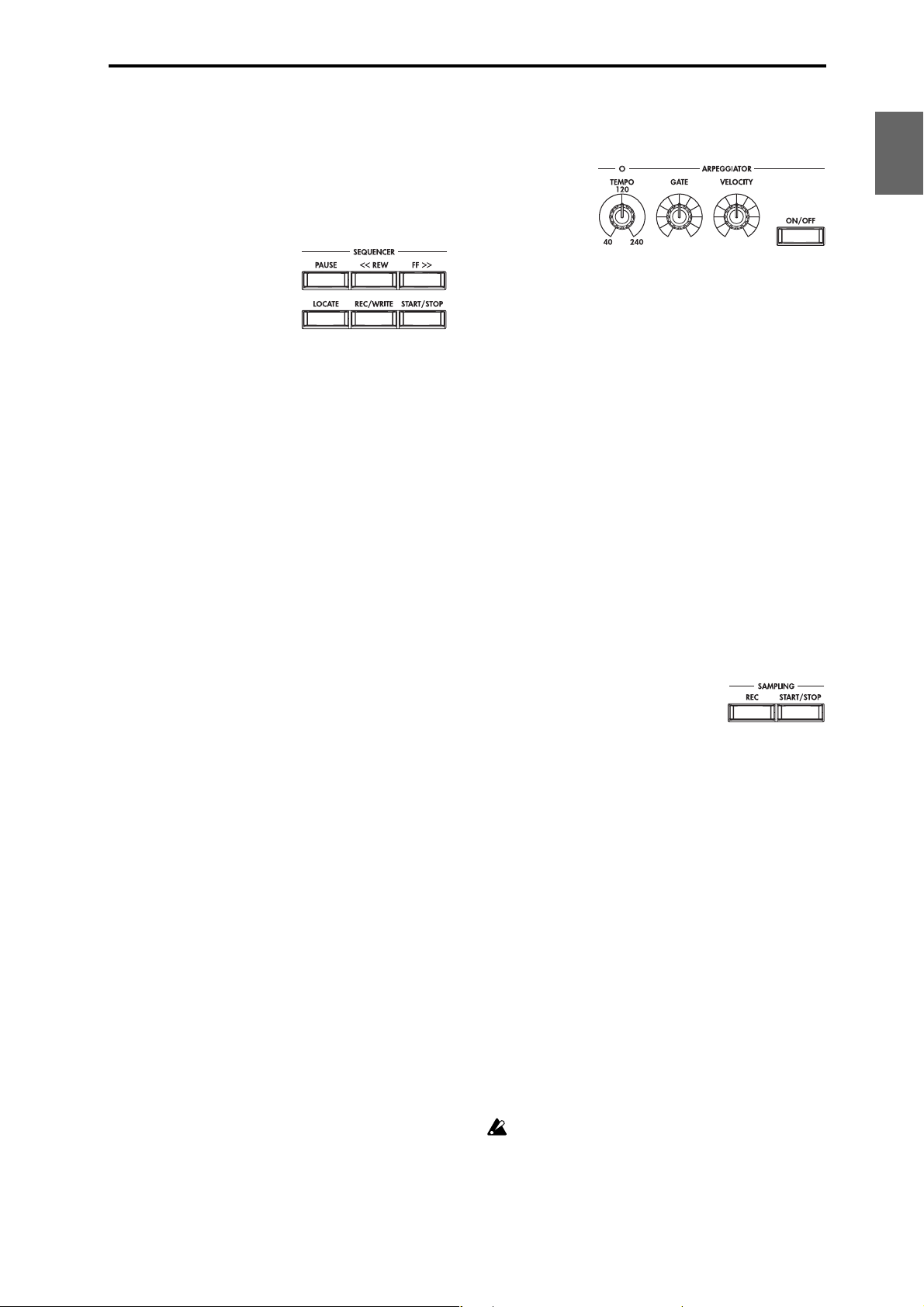
13. SEQUENCER
[PAUSE] key
In Sequencer mode, this key pauses the playback of the
song or cue list. In Song Play mode, this key pauses SMF
playback. When paused, the key will light. Press [PAUSE]
once again to resume playback; the key will turn off.
[<<REW] key
In Sequencer mode, this key will rewind the song or cue
list. When you press and hold this key, the key will light,
and the playback will rewind. (This key will not function
during recording.)
[FF>>] key
In Sequencer mode, this key will fast-forward the song or
cue list. When you press and hold this key, the key will
light, and the playback will fast-forward. (This key will
not function during recording.)
[LOCATE] key
In Sequencer mode, this key will advance or rewind the
song or cuelist playback to a specified point. In Song Play
mode, this key moves to the specified playback location
within the SMF data.
SEQUENCER [REC/WRITE] key
In Sequencer mode, pressing this key will make the key
light, and if you then press the SEQUENCER
STOP] key, recording will begin (☞p.43).
In Program, Combination and Global modes, pressing this
key will open a dialog box, and if you then press the OK
button, the edited contents will be written (☞p.114, 116).
In Program or Combination mode, you can hold down the
[ENTER] key and press this key to turn on the Auto Song
Setup function. (☞p.58)
[START/
SEQUENCER [START/STOP] key
This is the start/stop key for song or cue list recording
and playback in Sequencer mode, and SMF playback in
Song Play mode.
During recording and playback, the key will blink at the
current tempo.
These keys are also used to play an audio CD in the USBconnected CD-R/RW drive.
SEQUENCER [START/STOP] key : Play/Stop
[FF>>] key : Fast-forward
[<<REW] key : Rewind
[PAUSE] key : Pause
[LOCATE] key
: Move to the specified
location
14. ARPEGGIATOR
These knobs control the performance of the arpeggiator in
realtime (☞QS p.11).
[TEMPO] knob
This adjusts the base tempo of the arpeggiator and
sequencer. The LED will blink at quarter-note intervals of
the current tempo.
[GATE] knob
This adjusts the gate time (note duration) of the arpeggiated notes. At the center position (12 o’clock), the gate
time will be the same as the “Gate” parameter of the
arpeggiator. Rotating the knob toward the left will shorten
the gate time, and rotating it toward the right will
lengthen the gate time.
[VELOCITY] knob
This adjusts the velocity (playing strength) of the arpeggiated notes. At the center position (12 o’clock), the velocity
will be the same as the “Velocity” parameter of the arpeggiator. Rotating the knob toward the left will decrease the
velocity, and rotating it toward the right will increase the
velocity.
[ON/OFF] key
This switches the Arpeggiator function on/off. When on,
the key will light.
15. SAMPLING
SAMPLING [REC] key
In Sampling, Program, Combination, and Sequencer
modes, pressing this key will make the key light, and
when you continue by pressing the SAMPLING [START/
STOP] key, sampling will either begin or you will enter
the sample-ready mode.
SAMPLING [START/STOP] key
In Sampling, Program, Combination, and Sequencer
modes, pressing this key after pressing the SAMPLING
[REC] key will either cause sampling to begin, or it will
access the sample-ready mode.
In the Sampling P1: Sample Edit page, pressing this key
will sound the selected sample.
This key is also used to play back a WAVE file from the
media. This function can be used in the directory window
of various Media mode pages, in the Media mode Make
Audio CD page, and in the “Select Directory” page menu
dialog box of the Program, Combination, Sequencer, and
Sampling modes.
16. Valve cover
A 12AU7 (ECC82) vacuum tube (a.k.a. “valve”) is built-in.
The valve cover may break if subjected to impact. Be
particularly careful not to subject it to direct impact,
since this may also break the vacuum tube. If the
valve cover breaks, have it repaired immediately,
since failing to do so may cause the vacuum tube or
other parts to malfunction.
Introduction
Program
Combination
SequencerSamplingSong PlayGlobalEffectMedia, etcPresetOther
5
Page 10

17. Sample memory (RAM) slot cover
You can open this cover and install SIMM boards to
expand the sample memory (RAM). A maximum of three
32 Mbyte SIMM boards can be installed as sample memory (RAM). (☞PG p.321)
18. Headphone jack
A set of headphones can be connected here (stereo 1/4"
jack).
This allows stereo monitoring of the same signal as the
OUTPUT L/MONO and R jacks.
Rear panel
1. AC power supply connector
Connect the included power supply cable here.
After connecting the power supply cable to the TRITON
Extreme, connect the other end to an AC outlet (☞p.16).
2. [POWER] switch
This switch turns the power on/off (☞p.18).
3. AUDIO OUTPUT
Connect these outputs to the input jacks of your amp or
mixer. In addition to the L/MONO and R main stereo
audio outputs, the TRITON Extreme provides four individual audio outputs. The sound from each oscillator,
drum, timbre/track, or insert effect can be freely routed to
any output (☞p.104–).
(MAIN) L/MONO, R
These are unbalanced phone jacks.
These are the main audio output jacks. By setting “BUS
Select” to L/R, the output from an oscillator, an insert
effect, an individual drum part, or the metronome can be
output to the (MAIN) L/MONO and R jacks.
When making connections in stereo, use L/MONO and R.
When making connections in mono, use the L/MONO
jack.
(INDIVIDUAL) 1, 2, 3, 4
These are unbalanced phone jacks.
These are individual (independent) audio output jacks. By
setting the “BUS Select” to 1, 2, 3(Tube), 4(Tube), 1/2, or
3/4(Tube), an oscillator, an insert effect, an individual
drum part, or the metronome etc. can be assigned to be
output from the (INDIVIDUAL) 1, 2, 3, 4, jacks.
The output from the 1, 2, 3, 4 jacks is not affected by the
[VOLUME] slider.
4. AUDIO INPUT
These two audio inputs are used when recording a mono/
stereo sample from a mic or external audio source, or
when applying the TRITON Extreme’s internal effects to
an external audio source (☞p.64, 107, 111).
The MIC/LINE level select switch ([MIC/LINE] switch)
and the level adjustment knob ([LEVEL] knob) allow you
to use a wide range of external audio sources, ranging
from mic level to line level.
AUDIO INPUT 1/2 jacks
These are unbalanced phone jacks.
[LEVEL] knob
This adjusts the input level of the AUDIO INPUT 1/2
jacks.
[MIC/LINE] switch
This switches the input level of the AUDIO INPUT 1/2
jacks.
5. S/P DIF
OUT(MAIN) jack
This is an optical type S/P DIF format (IEC60958, EIAJ
CP-1201) digital output jack.
It outputs a digital version of the same audio signal as the
AUDIO OUTPUT (MAIN) L/MONO and R jacks, at sampling rates of 48 kHz.
6
Page 11

2
7 116 98 10
Introduction
1
Use an optical cable to connect this to the optical digital
input jack of a DAT or MD, etc.
The [VOLUME] slider does not adjust the output level of
this jack.
IN jack
This is an optical S/P DIF format (IEC 60958, EIAJ CP-
1201) digital input jack.
Digital audio at a sample rate of 48 kHz can be input here.
Use an optical cable to connect this jack to the optical digital output jack of a DAT or other device.
6. USB
USB A connector (for connecting a CD-R/RW drive,
etc.)
You can connect an external USB device to this connector.
Use this connector to connect storage media such as a
hard disk, MO, or CD-RW drive. (☞PG p.325)
USB B connector (for connecting to a computer)
You can connect your computer to this connector. This lets
you use your computer to access data on the TRITON
Extreme’s CompactFlash (Microdrive) card. This connection also lets you send and receive MIDI data between the
TRITON Extreme and your computer. (☞PG p.325)
What is USB?
USB stands for Universal Serial Bus, and is an interface
for transferring data between a computer, a keyboard
and/or peripheral devices.
7. MIDI
MIDI THRU connector
Musical data and sound settings etc. that are received at
the MIDI IN connector are re-transmitted without change
from the MIDI THRU connector.
You can use this to connect multiple MIDI devices (☞PG
p.288).
MIDI OUT connector
Musical data and sound settings etc. are transmitted from
this connector.
Use this to control another MIDI device connected via this
port to the TRITON Extreme (☞PG p.288).
345
8. DAMPER jack
An optional switch-type pedal such as the Korg DS-1H
damper pedal can be connected here.
If a DS-1H is connected, it will function as a half-damper
pedal. If another switch-type pedal is connected, it will
function as a damper switch. In order to ensure that the
pedal functions correctly, please adjust the polarity and
the half-damper sensitivity (☞PG p.157, 165).
9. ASSIGNABLE
SWITCH jack
An optional on/off foot switch such as the Korg PS-1 foot
switch can be connected here.
In Global mode you can specify the function of this
switch. For example, you can use it as a modulation controller, to select programs or combinations, to start/stop
the sequencer, or to set the tap tempo. (☞p.90).
PEDAL jack
An optional Korg EXP-2 or XVP-10 expression pedal can
be connected here.
Its function can be assigned in Global mode, allowing you
to use the pedal to control the volume etc. (☞p.90)
10. [Contrast adjustment] knob
This adjusts the contrast of the LCD screen.
The optimal setting will depend on the height or angle
from which you view the screen display, so please adjust
as necessary.
11. CF card slot
You can insert a CompactFlash or Microdrive into this
slot. The power must be off when inserting or removing
media. For details on how to handle these types of media,
refer to p.125.
Eject button
After making sure that the TRITON Extreme’s power is
turned off, press this button to remove the media. If the
media does not eject when you press this button, do not
attempt to remove the media by force. Contact a nearby
musical instrument dealer.
Program
Combination
SequencerSamplingSong PlayGlobalEffectMedia, etcPresetOther
MIDI IN connector
Musical data and sound settings etc. are received at this
connector.
Use this to play the TRITON Extreme from another MIDI
device connected to this port (☞PG p.288).
7
Page 12
Names and functions of objects in the LCD screen
The TRITON Extreme uses Korg’s TouchView graphical
user interface.
By touching objects displayed in the LCD screen, you can
select pages, set parameter values, rename programs and
combinations, write data, and perform many other operations.
References in the TRITON Extreme’s owner’s manual
to the “... button” or “... tab” refer to objects displayed
on the LCD screen. References to the “[...] key,” “[...]
knob,” “[...] dial,” or “[...] slider” refer to controls on
the front or rear panel of the TRITON Extreme.
a: Current page
b: Edit cell
d: Popup button (2)
f: Check box
c: Popup button (1)
g: Radio buttons
h: Tab
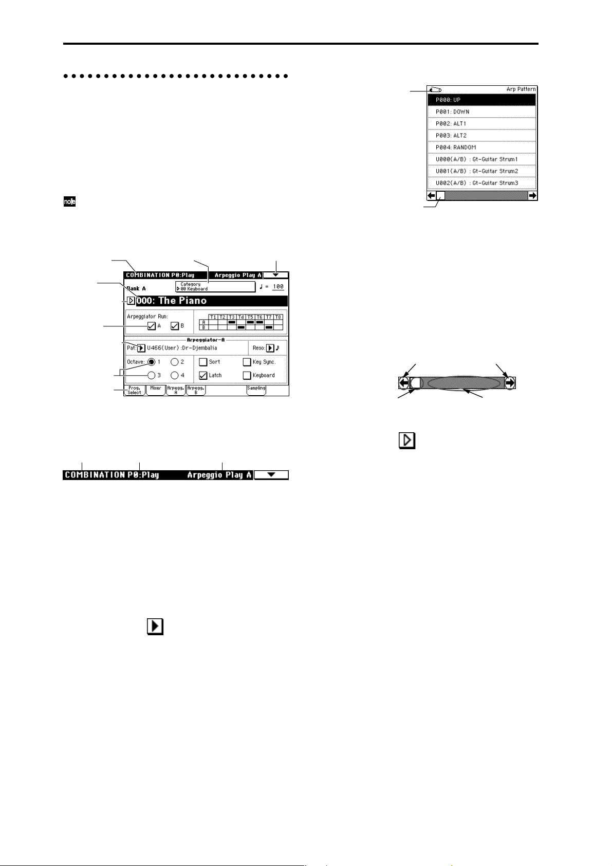
a: Current page
This indicates the selected page within the current mode.
From the left, this shows the mode name, page number,
and page name.
Mode name Page namePage number
b: Edit cell
When you press a parameter in the LCD screen, the
parameter or parameter value will sometimes be highlighted (displayed in inverse video). This is called the edit
cell, and the highlighted item will be subject to editing.
The parameter value of the edit cell can be modified using
the VALUE controllers (☞p.14) or by using a popup button in the LCD screen. For parameters that accept a note
number or a velocity value, you can also hold down the
[ENTER] key and play a note on the keyboard to enter the
note number or velocity value.
c: Popup button (1)
When this button is pressed, a popup menu will appear,
showing the parameter values that are available for selection.
To input the parameter value, press the desired value in
the popup menu.
When a popup menu is displayed, operating a VALUE
controller (☞p.14) will close the popup menu. If the
popup menu is unlocked (☞“Pin”), it will close if you
touch a location outside the popup menu.
i: Page menu buttone: (category) Popup button
* Popup menu
Pin
Scroll bar
Pin
This switches the popup menu display between locked
and unlocked.
When locked, the pin will be shown closed, and the
popup menu will remain displayed even after you press a
parameter value. When unlocked, the pin will be shown
opened, and the popup menu will close immediately
when you press a parameter value.
Scroll bar
Use this when you wish to see parameter values that
extend beyond what can be displayed in the screen at one
time.
Press here to scroll to left or right.
Press here and slide to left
or right to scroll to the
desired location.
Press here to scroll to
the corresponding
location.
d: Popup button (2)
When you press this button, a tabbed popup menu will
appear, allowing you to perform the following selections.
• “Bank/Program Select,” “Bank/Combination Select”:
Select programs or combinations by bank
• “Multisample Select”: Select a multisample for a
program oscillator by category (ROM multisamples
only)
• “Category/Effect Select”: Select an insert effect or
master effect by category
To close the tabbed popup menu, press the OK button
or Cancel button.
e: (Category) popup button
When you press this button, a tabbed popup menu will
appear, allowing you to perform the following selections.
• “Category/Program Select,” “Category/Combination
Select”: Select programs or combinations by category
To close the tabbed popup menu, press the OK button
or Cancel button.
8
Page 13
f: Check box
Each time you press a check box, a check mark will be
added or removed.
When checked, the parameter will function; when
unchecked, the parameter will not function.
g: Radio buttons
Press a radio button to select one value from two or more
choices.
h: Tab
Press the tab to select a page.
* Page jump menu
Introduction
i: Page menu button
When this button is pressed, a list of page menu commands will appear.
The page menu commands that appear will depend on
the currently selected page.
You can also select up to ten page menu commands by
holding down the [ENTER] key and pressing a numeric
key [0]–[9].
The page menu will close when you press the LCD screen
at a location other than the page menu, or when you press
the [EXIT] key.
* Dialog box
The dialog box that appears will depend on the currently
selected page menu command.
When selecting a program or combination number in a
dialog box, use the VALUE controllers (☞p.14) to input
the number.
To execute, press the OK button. To cancel without executing, press the Cancel button. (The operation will occur
when you press and release the button.) The dialog box
will close. The [EXIT] key corresponds to the Cancel button, Done button, and Exit button.
Text edit button
In Combination, Program, Sequencer, Sampling, Song
Play, or Global modes, you can press the front panel
[MENU] key to view a list of the pages in that mode. (As a
reminder, the page you were in before you pressed the
[MENU] key will have its top right corner bent over.) By
pressing one of the pages shown, you can move to that
page. (You can also move to the corresponding page by
pressing a numeric key [0]–[9].)
When you press the [EXIT] key, P0 will be displayed.
* Other objects
To modify the parameter value of an object shaped like a
slider or knob, press it to move the edit cell to that object,
and use the VALUE controllers to modify the value. In
addition, there are also buttons similar to the OK button
and Cancel button explained in “* dialog box” which execute an operation when they are pressed and released,
such as the Done button, Copy button, and Insert button.
Toggle buttons
This type of button will change its function or switch on/
off each time it is pressed.
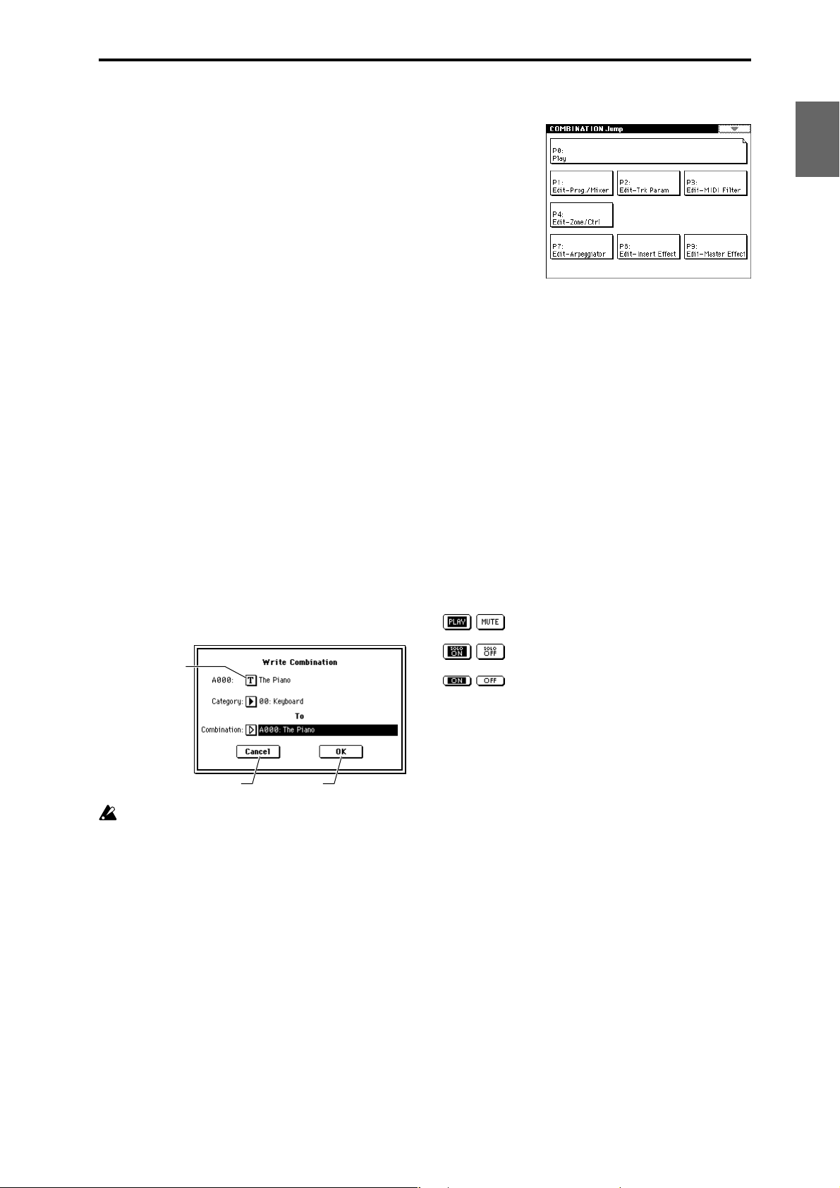
PLAY/MUTE/REC button in Sequencer
and Song Play mode
SOLO ON/OFF button in Sequencer and
Song Play mode
ON/OFF button for Insert Effect and Master Effect
Program
Combination
SequencerSamplingSong PlayGlobalEffectMedia, etcPresetOther
Cancel button OK button
After some commands are executed, the previouslylocked page menu will be unlocked automatically,
and the page menu will be closed.
* Text edit button
When you press this button, a text edit dialog box will
appear.
Here you can rename text (such as the name of a program,
combination, or song etc.) (☞p.115).
9
Page 14
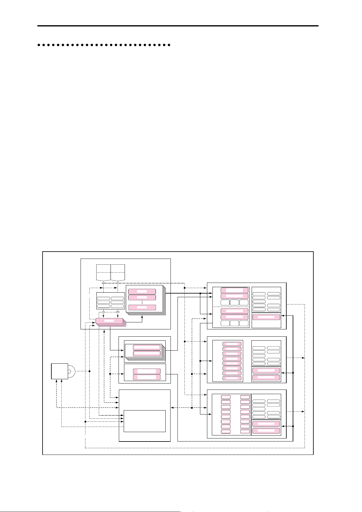
Overview of the TRITON Extreme’s modes
The TRITON Extreme has a large number of functions
that let you play and edit programs and combinations,
record and play sequence data, record and play back samples, and manage data on media. The largest unit used to
organize these functions is called a mode.
The TRITON Extreme has seven modes.
Program mode
• Select and play programs
You can choose programs from rewritable banks A–F
and H–N which contain a total of 1,664 programs, and
non-rewritable bank G (256 programs compatible with
the GM2 standard, and nine drum programs).
(The 128 programs of bank F can be selected only if the
EXB-MOSS option has been installed.)
• Sample or resample.
For example you can sample an external audio source
while listening to the performance of the arpeggiator,
or resample a performance you play using a program.
• Edit a program
Make settings for the oscillator, filter, amp, EG, LFO,
effects, valve force, and arpeggiator.
The following multisamples are available for the oscillator.
• 962 internal multisamples (160 Mbytes)
• Multisamples (RAM) that you sampled on the
TRITON Extreme or loaded in from media
(maximum of 96 Mbytes)
• Create drum programs using a drum kit (created in
Global mode)
Combination mode
• Select and play combinations
A combination is a set of two or more programs (up to
a maximum of eight), and allows you to produce complex sounds that could not be created by an individual
program.
You can choose combinations from rewritable banks
A–E and H–N which contain a total of 1,536 combinations.
• Sample or resample.
For example you can sample an external audio source
while listening to the performance of the arpeggiators,
or resample a performance you play using a combination.
• Edit a combination
Make settings for volume, pan, layer/split etc. for each
timbre (program), and make settings for effects, valve
force and the two arpeggiators.
CD-R/RW
CD-ROM Write Audio CD
Ripping
SAMPLING MODE
Resampling
Resampling
AUDIO INPUT
AUDIO INPUT
1
S/P DIF IN
S/P DIF IN
L
Insert Effect / Valve Force
IFX 4
IFX 1
IFX 5
IFX 2
IFX 3
Valve Force
Sample
Sample
Sample
Sample
2
R
Multisample
GLOBAL MODE
DRUM KIT
Key
Assign
ARPEGGIATOR PATTERN
MEDIA MODE
Multisample
Sample
Sample
Sample
Drumsample / Sample - H
Drumsample / Sample - L
Preset Arpeggio
Pattern: P0 - 4
User Arpeggio
Pattern: U00 - 506
Media
PROGRAM
OSC 1
Multisample - H
Drum Kit
Multisample - L
FILTER1 AMP1
PITCH1
OSC 2
Multisample - H
Multisample - L
FILTER2
PITCH2
COMBINATION
TIMBRE 1
PROGRAM
TIMBRE 2
PROGRAM
TIMBRE 3
PROGRAM
TIMBRE 4
PROGRAM
TIMBRE 5
PROGRAM
TIMBRE 6
PROGRAM
TIMBRE 7
PROGRAM
TIMBRE 8
PROGRAM
SEQUENCER / SONG PLAY
TRACK 1
TRACK 2
TRACK 3
TRACK 4
TRACK 5
TRACK 6
TRACK 7
TRACK 8
PROGRAM
PROGRAM
PROGRAM
PROGRAM
PROGRAM
PROGRAM
PROGRAM
PROGRAM
TRACK 9
TRACK 10
TRACK 11
TRACK 12
TRACK 13
TRACK 14
TRACK 15
TRACK 16
AMP2
PROGRAM
PROGRAM
PROGRAM
PROGRAM
PROGRAM
PROGRAM
PROGRAM
PROGRAM
Insert / Master Effect /
Valve Force
MFX 1
IFX 1
MFX 2
IFX 2
IFX 3
MEQ
IFX 4
IFX 5
Valve Force
Arpeggiator
Insert / Master Effect /
Valve Force
MFX 1
IFX 1
MFX 2
IFX 2
IFX 3
MEQ
IFX 4
Valve Force
IFX 5
Arpeggiator - A
Arpeggiator - B
Insert / Master Effect /
Valve Force
MFX 1
IFX 1
MFX 2
IFX 2
IFX 3
MEQ
IFX 4
Valve Force
IFX 5
Arpeggiator - A
Arpeggiator - B
Only SEQ
10
Page 15

Sequencer mode
• Use the 16-track MIDI sequencer to record and play
songs.
• Record onto the sixteen MIDI tracks individually or all
sixteen tracks at once. Exclusive messages can also be
recorded and edited.
• Perform sampling/resampling.
An external audio input source can be sampled in synchronization with the song playback. When doing so,
you can automatically create a note event that will be
used to trigger the resulting sample, letting you record
an external audio source just as if you were recording
onto an audio track. (This is called the “In-track Sampling” function.)
You can also resample the playback of a song. After
resampling your song to media, you can then use
Media mode to write the song to a CD-R/RW drive
connected to the TRITON Extreme’s USB A connector,
creating your own audio CD.
• Make effect and Valve Force settings for a song.
• You can record a performance that uses the
arpeggiator(s) into a song or pattern.
• You can use a cue list to create an arrangement using
individual songs for each verse, chorus, bridge, etc.,
and specify the number of repeats for each song.
• You can use a maximum of 20 cue lists, 200 songs, and
100 preset patterns. One song can use as many as 100
patterns.
• The TRITON Extreme can be used as a 16-part
multitimbral tone generator.
• Perform using the RPPR (Realtime Pattern Play/
Recording) function, and adjust the various settings.
Song Play mode
• SMF (Standard MIDI File) data can be played back
from a media, and you can perform along with the
playback.
• Make effect and valve force settings for use in Song
Play mode.
• The arpeggiator can be used while you play along
with the SMF playback.
• SMF songs can be played back in succession.
You can use the jukebox function to playback songs in
any specified order.
Global mode
• Make settings that affect the entire TRITON Extreme,
such as master tune and global MIDI channel.
• Create user drum kits (144 kits), user arpeggio
patterns (507 patterns), and user scales (16 one-octave
scales and 1 all-note scale).
• Create drum kits using the 1,171 internal drum
samples (ROM). You can also use RAM samples that
you created on the TRITON Extreme or loaded from
media.
• Rename program and combination categories.
• Set the function of the assignable pedals and
assignable switches.
• Transmit data dumps of MIDI exclusive data.
Media mode
• Data of each mode can be saved and loaded using
CompactFlash or Microdrive media.
• Format the above types of media. You can also
manage data by copying it, etc.
• Korg, AKAI, AIFF, and WAVE format sample data can
be loaded. Sample data can also be saved in Korg
format, or exported in AIFF or WAVE formats.
• Songs that you created in Sequencer mode can be
saved in SMF format. SMF files can be loaded as
Sequencer mode songs.
• You can use the Data Filer function (to save/load
MIDI exclusive data).
• Edit Wave files.
• Specify the song order of Wave files and use a CD-R/
RW drive connected to the USB A connector to create
an audio CD. You can also play back audio CDs.
• Use a computer connected to the USB B connector to
manage (e.g., copy or delete) data on media inserted in
the TRITON Extreme’s CF card slot. (USB storage
mode)
Introduction
Program
Combination
SequencerSamplingSong PlayGlobalEffectMedia, etcPresetOther
Sampling mode
• Sample external audio sources (i.e., record samples).
Insert effects, valve force can be applied to the external
input sound while you sample.
• Edit the waveform data you sampled or waveform
data that you loaded in from media, and set loop
points etc.
• Edit multisamples consisting of two or more samples.
•A multisample can be converted into a program, so
that a multisample created in Sampling mode can be
used in the Program, Combination, Sequencer, or Song
Play modes.
• “Rip” (directly sample) digital data from an audio CD
in a CD-R/RW drive connected to the USB A
connector. You can also play back audio CDs.
11
Page 16
About polyphony
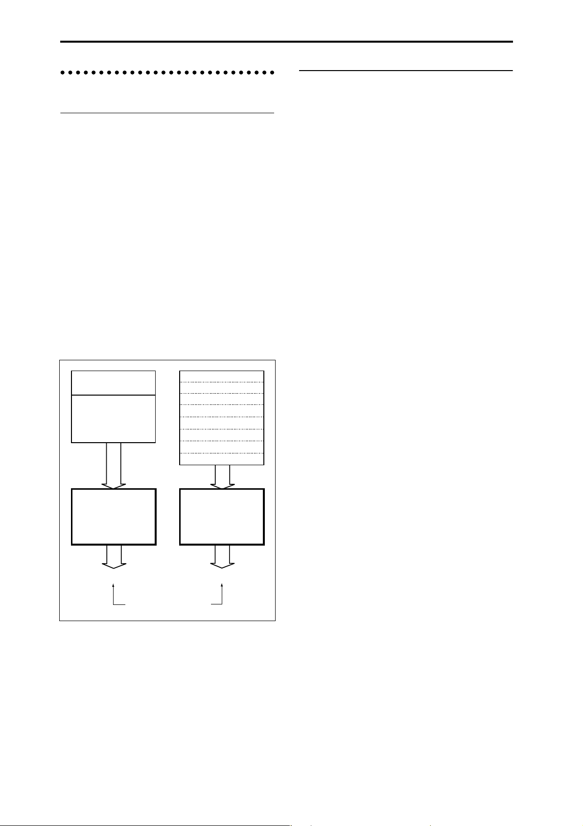
Tone generators and oscillators
Each oscillator in the TRITON Extreme is sounded by one
of two Tone Generators.
Each tone generator is connected to the various PCM
memories as shown in the diagram below.
Tone Generator 1
• ROM: Internal PCM ROM (32 Mbytes)
• RAM: User sample memory (16 Mbytes, expandable
to a maximum of 96 Mbytes)
Tone Generator 2
• Piano:
• New1:
• New2:
• Best:
• OrchS:
• OrchB:
•Vint:
• Synth:
Internal PCM ROM (128 Mbytes)
Number of voices in each mode
The maximum number of voices that can be played simultaneously will depend on the oscillator mode of the program.
• For a Single/Drum-mode program, 1 oscillator = 1
voice
• For a Double-mode program, 2 oscillators = 1 voice
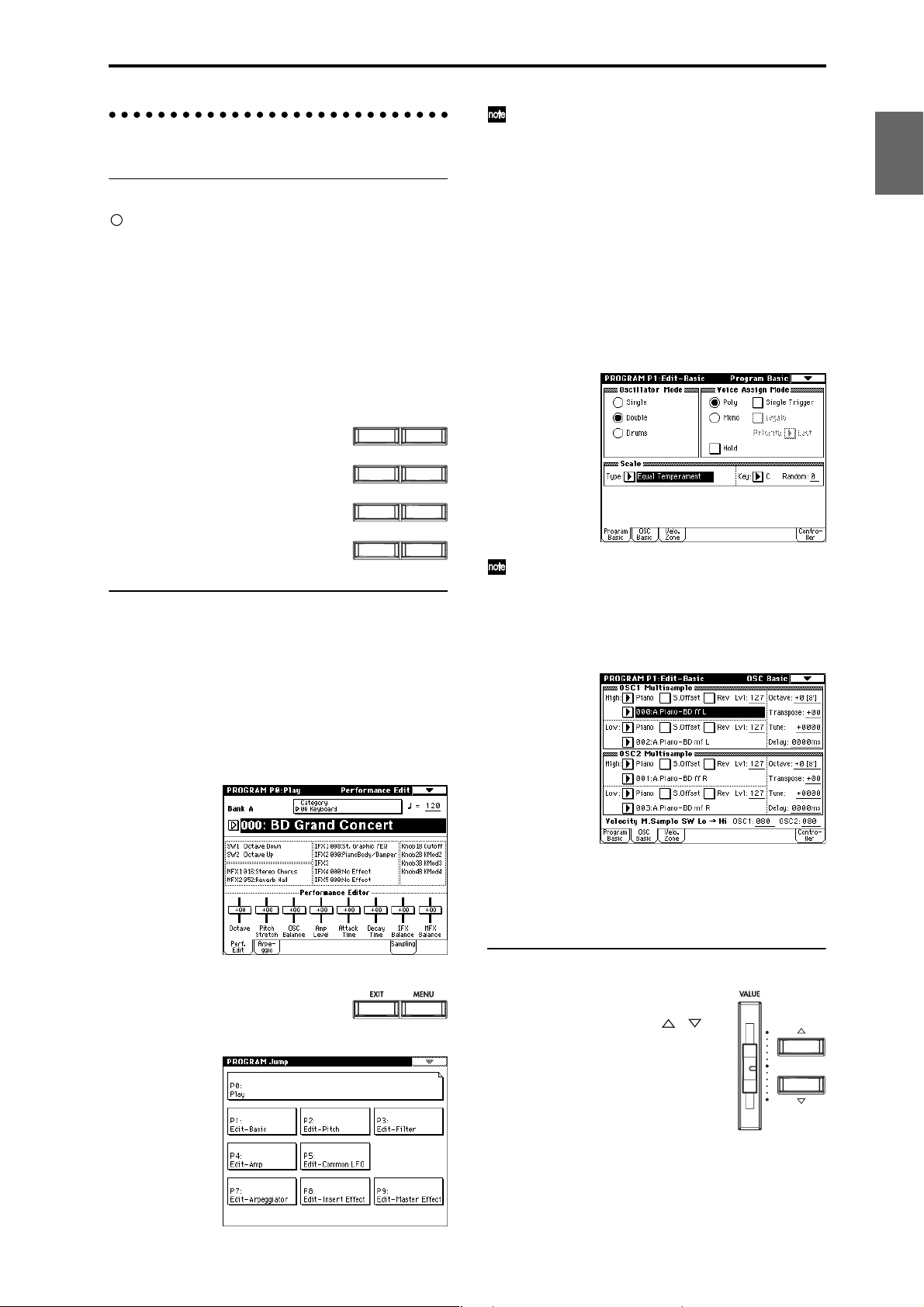
Program mode
Single/Drums (“Oscillator Mode”)
Normally, 60 voices can be used.
However a maximum of 120 voices will be available if, for
example, ROM or RAM is used for the High MS, and
Piano–Synth is used for the Low MS, and you use velocity
switching to play the two tone generators.
Double (“Oscillator Mode”)
Normally, 30 voices can be used.
However if OSC1 is sounded by one tone generator and
OSC2 is sounded by the other tone generator (e.g.,
OSC1=ROM, OSC2=Piano–Synth), a maximum of 60
voices can be used. If OSC1 and OSC2 use one tone generator (e.g., OSC1=ROM, OSC2=ROM), then a maximum of
30 voices can be used.
This can also be increased by velocity switch and velocity
zone settings.
PCM memory
ROM (Internal PCM ROM)
RAM
(User sample memory)
Tone Generator 1
Maximum 60 oscillators
32 Mbytes
96 Mbytes*
* = Expandable to a maximum.
Factory settings is 16 Mbytes
Total maximum 120 oscillators
PCM memory
Piano (Internal PCM ROM)
New1 ( " )
New2 ( " )
Best ( " )
OrchS( " )
OrchB( " )
Vint ( " )
Synth ( " )
Tone Generator 2
Maximum 60 oscillators
16 Mbytes
16 Mbytes
16 Mbytes
16 Mbytes
16 Mbytes
16 Mbytes
16 Mbytes
16 Mbytes
Total 128 Mbytes
Each tone generator is able to simultaneously sound up to
60 oscillators (i.e., to play the PCM data connected to that
tone generator). Together, the two tone generators are able
to sound up to 120 oscillators.
For example up to 60 oscillators can use the ROM, and up
to 60 oscillators can use the Piano, making a total of 120
oscillators. However, you can’t play 61 or more oscillators
from the ROM alone.
Combination, Sequencer, and Song Play modes
Depending on the oscillator mode of the programs you
are using, the maximum number will vary between 60
voices and 120 voices.
(Example)
For single-mode programs that use ROM or RAM, a total
maximum of 60 voices
For single-mode programs that use Piano–Synth, a total
maximum of 60 voices
Total 120 voices
For double-mode programs that use ROM or RAM, a total
maximum of 30 voices
For double-mode programs that use Piano–Synth, a total
maximum of 30 voices
Total 60 voices
Sampling mode
Tone generator 1 is always used in Sampling mode.
Mono samples/multisamples
60 voices.
Stereo samples/multisamples
30 voices.
12
Page 17
Basic operation
1. Selecting modes
In order to use a particular function on the TRITON
Extreme, you must first select the appropriate mode.
Press one of the front panel mode keys ([COMBI] key
– [MEDIA] key) to enter the corresponding mode.
[COMBI] key: Combination mode
[PROG] key: Program mode
[SEQ] key: Sequencer mode
[SAMPLING] key: Sampling mode
[S.PLAY] key: Song Play mode
[GLOBAL] key: Global mode
[MEDIA] key: Media mode
In Media mode there is only one page, so the page
jump menu will not appear.
3 In the LCD screen, press the desired page.
You will jump to the selected page, and it will appear
in the display. As an example here, press P1: Edit-Basic.
• As a reminder, the page that was selected before you
pressed the [MENU] key will have its top right corner
bent over.
• You can also jump to the corresponding page by
pressing a numeric key [0]–[9]. (P0–P9 correspond to
numeric keys [0]–[9].)
• By holding down the [MENU] key and pressing a
numeric key [0]–[9], you can jump directly to the
corresponding page without displaying the page jump
menu.
PROGCOMBI
Introduction
Program
Combination
SAMPLINGSEQ
GLOBALS.PLAY
COMPAREMEDIA
2. Selecting pages
Each mode has a large number of parameters, which are
organized into pages.
These are further subdivided by tabs into up to eight tab
pages.
1 Make sure that the desired mode is selected.
To select a mode, press the appropriate mode key
([COMBI] key – [MEDIA] key).
Here we will use Program mode as an example for our
explanation. Press the [PROG] key.
2 Press the [MENU] key.
The page jump menu will appear.
SequencerSamplingSong PlayGlobalEffectMedia, etcPresetOther
When you press the [EXIT] key, you will return to P0
from any page.
4 Press one of the tabs located at the bottom of the
page.
As an example here, press the OSC Basic tab which is
the second from the left.
• Some pages have no tabs.
5 To move to a page with a different ‘P’ number, press
the [MENU] key and continue from step 2 of this
procedure.
3. Setting a parameter
The parameter value in the edit cell can
be set by using the front panel VALUE
controllers ([VALUE] slider, [ ][ ]
keys, [V ALUE] dial, numeric keys [0]–[9],
[–] key, [ENTER] key, and [./10’s HOLD]
key). As necessary, you can also use the
[BANK] keys and the [COMPARE] key.
For some parameters, the value can be set
by pressing a popup button to display
the popup menu and then selecting a
parameter value, or by holding down the [ENTER] key
and playing a note on the keyboard to input a note number or velocity value.
13
Page 18
VALUE controllers
[VALUE] slider
Use this when you wish to make major changes in the
value.
In Program mode and Combination mode, this slider can
also be used as a control source for alternate modulation
or dynamic modulation. (This is active in Program or
Combination P0: Play when the “Program Select” or
“Combination Select” (the large characters in the upper
part of the LCD) is selected).
[][] keys
Use these when you wish to make small changes in the
value.
[VALUE] dial
Use this when you wish to make large changes in a value.
Numeric keys [0]–[9], [ENTER] key, [–] key,
[./10’s HOLD] key
Use these when you know the parameter value that you
wish to input.
After using the numeric keys [0]–[9] to input a number,
press the [ENTER] key to finalize the parameter value.
Use the [–] key to enter negative numbers.
Use the [./10’s HOLD] key to enter a decimal point.
In Program and Combination mode P0: Play page other
than the Sampling page, the [./10’s HOLD] key performs
the 10’s Hold function. (☞p.21, 32)
BANK [A]–[G], [H]–[N] keys
If you edit the settings that are recalled by pressing the
[COMPARE] key (i.e., the settings that are written into
memory), the LED will go dark, and it will not be possible
to return to the previous edits by pressing the [COMPARE] key again.
In Sequencer mode, you can use the [COMPARE] key to
make “before and after” comparisons immediately after
using realtime recording or step recording to record a
song, or after performing a track edit operation.
For example, this can be used effectively when realtimerecording a track for a song.
1 Realtime-record a MIDI track. (Take 1)
2 Once again, realtime-record on the same track. (Take 2)
3 Press the [COMPARE] key. The LED will light, and
take 1 will be recalled.
4 Press the [COMP ARE] key once again. The LED will go
dark, and take 2 will be recalled.
5 If at step 3 you once again realtime-record on the
same track (take 3), the object of the Compare function
will now be take 1. If at step 4 you once again realtime-record on the same track (take 3), the object of the
Compare function will be take 2.
In this way, the Compare function lets you recall the previous recording or the previous state of event editing.
The Compare function is not available Sampling,
Song Play, Global, or Media modes.
Popup buttons and popup menus
You can press a popup button to access a popup menu,
and then set parameter values (☞p.8).
Keyboard input
When inputting a note number or a specific velocity as the
value of a parameter, you can use the keyboard to input
the setting. Hold down the [ENTER] key and play the
note that you wish to enter as a value. The note number or
velocity value will be input.
When the Global P5: Drum Kit page is displayed, you can
hold down the [ENTER] key and play a note to recall the
settings that have been assigned to that note.
In Sampling mode, you can hold down the [ENTER] key
and play a note to recall the index that is assigned to that
note.
The BANK [A]–[G], [H]–[N] keys are used in Program
mode to select the program bank and in Combination
mode to select the combination bank. In combination,
Sequencer and Song Play modes, these keys are used to
select the bank of the program used by each timbre/track.
[COMPARE] key
Use this key when you wish to compare the edits you
have made to a program or combination’s sound with the
un-edited original (i.e., the sound that is written into
memory).
When editing a program or combination, press this key.
The LED will light, and the last-written settings for that
program number or combination number will be recalled.
When you press the [COMP ARE] key once again, the LED
will go dark and you will return to the settings that you
were editing.
14
Page 19
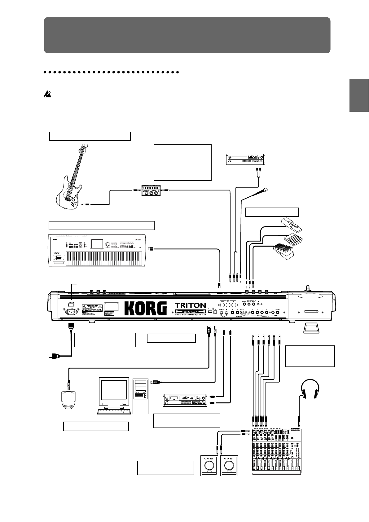
Connections
Connections must be made with the power turned
off. Please be aware that careless operation may damage your speaker system or cause malfunctions.
3. Analog audio input connections
Effect processor etc.
Setup
If a passive type guitar (a guitar
without an internal preamp) is
connected, it will not be possible
to sample at an appropriate level
due to the impedance mismatch.
Such instruments must be
connected via a preamp or effect
unit.
CD player,
analog record player, etc.
AUDIO OUTPUT/
AUX OUT etc.
SetupProgram
Combination
Mic
8. Connections to MIDI equipment/computers
Power Switch
AC power supply
1. Connecting the power
cable
Power cable (Included)
to an AC outlet
MIDI OUT
9. Installing options
Option EXB-MOSS
SIMM
USB cable
DAT etc.
MIDI cable
USB A B
DIGITAL IN
MIDI IN
AUDIO
INPUT 1, 2
S/P DIF
OUT IN
5. Connecting pedals
DAMPER
ASSIGNABLE
SWITCH
PEDAL
AUDIO OUTPUT
(INDIVIDUAL) (MAIN)
4321RL/MONO
CF
CompactFlash
Microdrive card
6. Inserting and
removing CF card
slot media
SequencerSamplingSong PlayGlobalEffectMedia, etcPresetOther
CD-R/RW, hard disk,
removable disks etc.
7. Connecting a USB device
Computer
4. Digital audio input/output
connections
2. Analog audio output
connections
DIGITAL OUT
INPUT
Powered monitors,
etc.
Monitor
OUTPUT
MIC1
BAL
BAL
BAL
OR
OR
OR
UNBAL
UNBAL
UNBAL
LINE IN 3
LINE IN 2
LINE IN 1
LOW CUT
LOW CUT
LOW CUT
75Hz
75Hz
75Hz
18dB/OCT
18dB/OCT
18dB/OCT
B
d
V
B
B
d
d
V
V
0
0
0
1
1
1
-
-
-
G
A
G
G
A
A
I
C
I
I
C
N
C
N
N
I
I
I
M
M
M
U
U
U
10
10
60
10
60
60
+10dB
-40dB
+10dB
+10dB
-40dB
-40dB
TRIM
TRIM
TRIM
U
U
U
AUX
AUX
AUX
1
1
1
MON/
MON/
MON/
EFX
EFX
EFX
+15
+15
+15
U
U
U
2
2
2
EFX
EFX
EFX
+15
+15
+15
U
U
U
EQ
EQ
EQ
HI
HI
HI
12kHz
12kHz
12kHz
-15
-15
+15
+15
-15
+15
U
U
U
MID
MID
MID
2.5kHz
2.5kHz
2.5kHz
-12
-12
-12
+12
+12
+12
U
U
U
LOW
LOW
LOW
80Hz
80Hz
80Hz
+15
+15
+15
-15
-15
-15
PAN
PAN
PAN
L
L
L
R
R
R
1
3
2
MUTE
MUTE
MUTE
ALT 3–4
ALT 3–4
ALT 3–4
dB
dB
dB
10
10
10
SOLO
SOLO
SOLO
5
5
5
U
U
U
5
5
5
10
10
10
20
20
20
30
30
30
40
40
40
50
50
50
60
60
60
1
1
INPUT
L
2
2
R
ALL BAL/UNBAL
LEFT(1/MONO)
RIGHT
BAL
BAL
BAL
MONO
MONO
OR
OR
OR
UNBAL
UNBAL
UNBAL
L
L
LINE IN 4
LINE IN 6
LINE IN 5
BAL
BAL
LOW CUT
OR
LOW CUT
OR
LOW CUT
75Hz
75Hz
75Hz
UNBAL
UNBAL
18dB/OCT
18dB/OCT
18dB/OCT
B
d
V
0
B
B
d
V
d
V
0
1
0
1
-
1
-
-
R
R
G
A
G
A
G
A
I
C
N
I
I
I
C
C
N
N
I
I
M
M
M
U
U
U
LEVEL
LEVEL
+4
+4
10
60
10
10
60
60
-10
-10
+10dB
-40dB
+10dB
-40dB
+10dB
-40dB
TRIM
LINE IN 7-8
LINE IN 9-10
LINE IN 11-12
TRIM
TRIM
U
U
U
U
U
U
AUX
AUX
AUX
AUX
AUX
1
1
1
1
1
MON/
MON/
MON/
MON/
MON/
EFX
EFX
EFX
EFX
EFX
+15
+15
+15
+15
+15
U
U
U
U
U
U
2
2
2
2
2
EFX
EFX
EFX
EFX
EFX
+15
+15
+15
+15
+15
U
U
U
U
U
U
EQ
EQ
EQ
EQ
EQ
HI
HI
HI
HI
HI
12kHz
12kHz
12kHz
12kHz
12kHz
-15
+15
-15
-15
+15
-15
-15
+15
+15
-15
+15
U
U
U
U
U
U
MID
MID
MID
MID
MID
2.5kHz
2.5kHz
2.5kHz
2.5kHz
2.5kHz
-12
+12
-12
-12
+12
-12
-12
-12
+12
+12
+12
U
U
U
U
U
U
LOW
LOW
LOW
LOW
LOW
80Hz
80Hz
80Hz
80Hz
80Hz
+15
-15
+15
-15
-15
+15
+15
+15
-15
-15
-15
PAN
PAN
PAN
PAN
PAN
L
R
L
L
R
L
L
L
R
R
R
9–10
11–12
6
7–8
4
5
MUTE
MUTE
MUTE
MUTE
MUTE
MUTE
ALT 3–4
ALT 3–4
ALT 3–4
ALT 3–4
ALT 3–4
ALT 3–4
dB
dB
dB
dB
dB
dB
10
10
10
10
10
10
SOLO
SOLO
SOLO
SOLO
SOLO
5
5
5
5
5
5
U
U
U
U
U
U
5
5
5
5
5
5
10
10
10
10
10
10
20
20
20
20
20
20
30
30
30
30
30
30
40
40
40
40
40
40
50
50
50
50
50
50
60
60
60
60
60
60
INPUT
TAPE
STEREO AUX RETURNS
AUX SEND
MIC4
MIC6
MIC3
MIC5
MIC2
PHONES
MAIN OUTS
TAPE
L
OUTPUT
MICRO SERIES 1402-VLZ
14-CHANNEL MIC/LINE MIXER
R
BAL/UNBAL
MONO
MONO
L
L
BAL
BAL
OR
OR
UNBAL
UNBAL
R
R
LEVEL
LEVEL
+4
+4
PHONES
-10
-10
LINE IN 13-14
U
U
U
AUX
AUX
1
1
MON/
MON/
EFX
EFX
1
+20
+10
+15
+15
NORMALLED
U
U
AUX 1 MASTER
2
PRE
2
2
POST
EFX
EFX
AUX
EFX TO
AUX 1
+20
MONITOR
+15
SELECT
+15
RETURNS
U
SOURCE
EQ
EQ
LEFT RIGHT
HI
HI
MAIN
CLIP+28
12kHz
12kHz
MIX
+10
-15
+15
+15
+7
U
ALT
+4
3-4
MID
MID
2.5kHz
2.5kHz
+2
-12
+12
+12
0
TAPE
U
-2
LOW
LOW
80Hz
80Hz
-4
+15
+15
-15
-7
ASSIGN
PAN
PAN
-10
TO MAIN MIX
-20
NORMAL(AFL)
-30
LEVEL SET(PFL)
L
R
R
SOLO
0dB=0dBu
MODE
13–14
MUTE
POWER
RUDE SOLO LIGHT
PHANTOM
ALT 3–4
CONTROL
/ PHONES
MAIN MIX
ROOM
dB
dB
dB
10
10
10
SOLO
SOLO
5
5
5
U
U
U
5
5
5
10
10
10
20
20
20
30
30
30
40
40
40
50
50
50
60
60
60
Mixer
15
Page 20
1. Connecting the power cable
1 Turn off the power of the TRITON Extreme.
2 Plug the included power cable into the AC power
supply connector located on the back of the TRITON
Extreme.
3 Connect the other end of the power cable to an AC
outlet.
Use only the power cable that is included with the
TRITON Extreme. Using another power cable may
cause malfunctions.
Make sure that your AC outlet is the correct voltage
for your instrument.
2. Analog audio output connections
Connect a set of amplified monitor speakers or your audio
system to the TRITON Extreme.
If you play back the TRITON Extreme through your
stereo audio system, be aware that high volumes may
damage your speakers. Be careful not to raise the volume excessively.
Connecting the AUDIO OUTPUT (MAIN) L/MONO,
R, (INDIVIDUAL) 1, 2, 3, and 4 jacks to the INPUT
jacks of your mixer or powered monitor system.
L/MONO and R are the main outputs. If you are outputting in stereo, make your connections using the
(MAIN) L/MONO jack and the R jack. If you are outputting in mono, make your connection to the (MAIN)
L/MONO jack.
The (INDIVIDUAL) 1, 2, 3, and 4 jacks are used to output specific sounds independently. For example, you
can use these to apply an external effect to the snare
sound of a drum kit.
When you are sampling, and want to hear the sounds
played by the TRITON Extreme’s sequencer while you
sample only the external audio source, send the source
to (INDIVIDUAL) 1 and 2. If you want to monitor this
sound, you can connect (INDIVIDUAL) 1 and 2 jacks
to your mixer, and monitor the sound via your mixer.
Headphones
If you are using headphones, connect them to the
headphone jack of the TRITON Extreme.
The TRITON Extreme’s headphone jack will output the
same signal as (MAIN) L/MONO and R.
If you are using (INDIVIDUAL) 1, 2, 3, and 4, connect
these jacks to your mixer, and use the headphone jack
of your mixer to monitor the sound.
3. Analog audio input connections
You can input external analog audio sources, and sample
them or process them with the internal effects and output
them from the OUTPUT jacks.
Connect mics or the OUTPUT jacks of your external
audio equipment to the AUDIO INPUT 1 and 2 jacks.
4. Digital audio input/output connections
Digital audio output
The same audio signal present at the TRITON Extreme’s
AUDIO OUTPUT (MAIN) L/MONO and R jacks can be
output in digital format to a DAT, MD, or digital multitrack recorder that can accept a digital audio input with a
sample frequency of 48 kHz.
Use an optical cable to connect the S/P DIF OUT
(MAIN) jack to the optical digital input jack of your
DAT, MD, or digital multitrack recorder.
The [VOLUME] slider does not affect the volume of
this output jack.
Digital audio input
TRITON Extreme can accept a digital audio input from a
DAT or other digital device that can output digital audio
at a sampling frequency of 48 kHz. This signal can be
input to the L and R channels, then sampled or processed
by the internal effects and output from the OUTPUT jacks.
Use an optical cable to connect the optical digital output jacks of your DAT etc. to the S/P DIF IN jack.
5. Connecting pedals
Foot pedal connections
A foot pedal can be used to control various synthesis and
effect parameters.
Connect an optional expression pedal such as the Korg
XVP-10 or EXP-2 to the rear panel ASSIGNABLE PEDAL
jack.
The function controlled by the foot pedal is specified in
Global: P2 “Foot Pedal Assign” (☞p.90, PG p.165, 282)
Foot switch connections
A foot switch controls sostenuto, soft pedal on/off, arpeggiator on/off, to select programs or combinations, and to
start/stop the sequencer and tap tempo etc.
Connect an optional foot switch such as the Korg PS-1 to
the rear panel ASSIGNABLE SWITCH jack.
The function assigned to the foot switch and the polarity
of the foot switch can be set in Global: P2 “Foot Switch
Assign,” and “Foot Switch Polarity” (☞p.90, PG p.165,
281)
16
Damper pedal connections
This pedal applies a piano style damper effect as you play .
Connect an optional footswitch to the DAMPER jack of
the TRITON Extreme. If a Korg DS-1H is connected, halfdamper effects can be produced.
The polarity of the pedal is set in Global P2: Controller
“Damper Polarity” and the sensitivity is set in Global P0
“Half Damper Calibration.” (☞PG p.157, 165)
Page 21
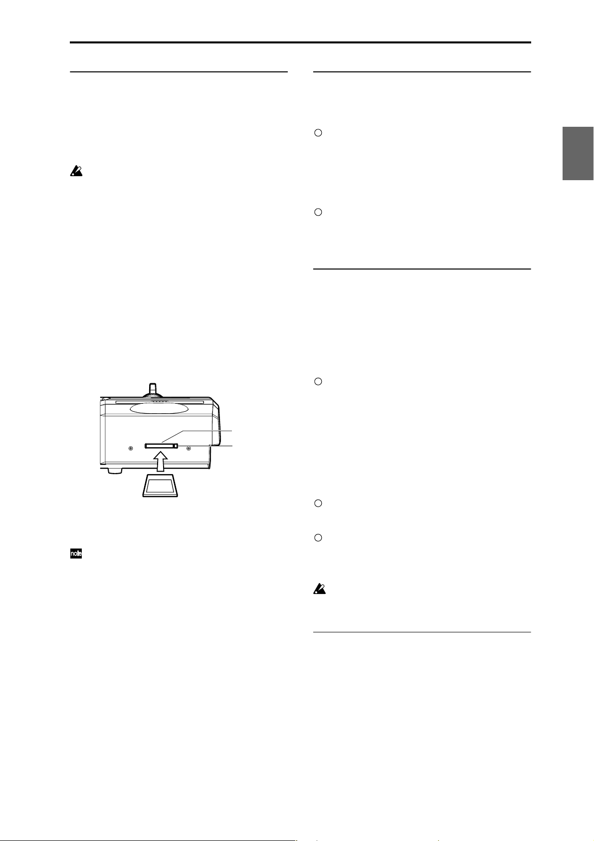
6. Inserting and removing CF card slot
media
You can insert a CompactFlash or Microdrive card into the
CF card slot, and use it to save or load song data or sample data.
When using a Microdrive, you can save the sampled data
directly to media.
The TRITON Extreme’s CF card slot does not support
hot-plugging. You must turn off the power before
inserting or removing CF card slot media. T urning off
the TRITON Extreme to insert media into the CF slot
will cause your unsaved sequence and sample data to
be lost; so we suggest you always insert your media
before you turn the TRITON Extreme on, in case you
want to save any of the data you create.
Inserting media
1 Turn off the power of the TRITON Extreme.
2 Make sure that the CF card slot eject button located
on the rear panel is pressed inward.
If the eject button is in the outward position, press it in.
3 Insert your CompactFlash or Microdrive card into the
CF card slot.
Make sure that the card is oriented correctly; the label
should be upward, and the connector end inserted
first.
CF card slot
Eject button
CompactFlash
Microdrive
4 Push the card in until the media is inserted all the
way into the slot.
5 Turn on the power.
To verify that the media was recognized correctly,
check that the Media mode “Media Select” display
shows CF (CompactFlash) or MD (Microdrive).
(☞p.119)
If the display indicates Unformatted, you will need to
format the card. Newly purchased media or media
that has been used by another device must also be
formatted before you use it on the TRITON Extreme
for the first time. For the formatting procedure, refer
to p.119.
Removing media
1 Turn off the power of the TRITON Extreme.
2 Press the CF card slot eject button located on the rear
panel, and pull the button outward.
3 Press the CF card slot eject button inward, and then
pull the media out of the connector inside the slot.
4 Remove the media from the slot.
Store the media correctly as described in the instructions included with the media.
7. Connecting a USB device
You can connect an external USB device such as a hard
disk or CD-R/RW drive to the USB A connector, and
transfer data to and from the device.
Connect the TRITON Extreme’s USB A connector to
the USB connector of your external USB device.
If you connect the TRITON Extreme’s USB B connector to
your computer, you will be able to transfer data to and
from your computer. You can also send and receive MIDI
data to/from your sequencer software or similar application.
Connect the TRITON Extreme’s USB B connector to
the USB connector of your computer.
☞ For details on connecting USB devices, refer to PG
p.325.
8. Connections to MIDI equipment/
computers
Connections to MIDI equipment
The keyboard, controllers, and sequencer etc. of TRITON
Extreme can be used to control an external MIDI tone generator. Conversely, another MIDI keyboard or sequencer
can control the tone generator of TRITON Extreme to produce sound.
Use MIDI cables to connect the MIDI connectors of
TRITON Extreme with the MIDI connectors of your
external device.
☞ PG p.288 “MIDI applications – Connecting MIDI
devices/computers”
Connections to a computer
Your performance on the TRITON Extreme, as well as
controller and sequencer data, can be sent to a computer
(connected via MIDI interface), and the tone generator of
TRITON Extreme can be played from the computer.
Use a MIDI interface to connect the MIDI connectors
of TRITON Extreme to the MIDI connectors of your
computer.
Connect the TRITON Extreme’s USB B connector to
the USB connector of your computer.
☞ PG p.288 “MIDI applications – Connecting MIDI
devices/computers”
Some USB-MIDI interfaces may not be able to transmit or receive the TRITON Extreme’s MIDI exclusive
messages.
9. Installing options
The functionality of the TRITON Extreme can be extended
by installing option boards and/or sample memory. The
following two types of options can be installed. For details
on installation, refer to PG p.319.
• EXB-MOSS (DSP synthesizer board)
• DRAM SIMM (Memory boards for sample data)
SetupProgram
Combination
SequencerSamplingSong PlayGlobalEffectMedia, etcPresetOther
17
Page 22
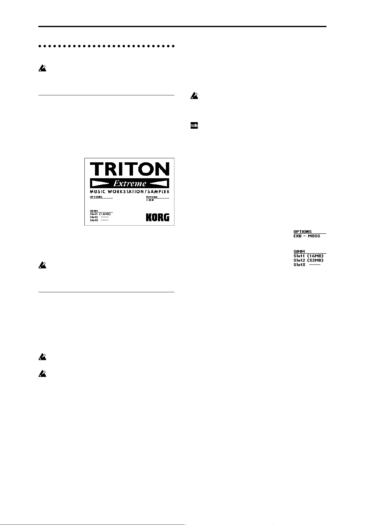
Turning the power on/off
Before you turn on the power, make sure that the
desired connections have been made as described in
“Connections” (☞p.15).
1. Turning the power on
1 Press the rear panel [POWER] switch to turn on the
power.
The LCD screen will display the name of your model,
and the software version.
(The following graphic shows the factory-set LCD
screen. The version number is subject to change without notice.)
2 Turn on your powered monitors or stereo amp.
3 Raise the TRITON Extreme’s [VOLUME] slider to an
appropriate level, and adjust the volume of your
powered monitors or stereo amp.
You must turn off the power before inserting media
into the CF card slot. The TRITON Extreme’s CF card
slot does not support hot-plugging.
2. Turning the power off
1 Set the front panel [VOLUME] slider and the volume
of your powered monitor or stereo amp to zero.
2 Turn off the power of your powered monitor or stereo
amp.
3 Press the TRITON Extreme’s [POWER] switch to turn
off the power.
Never turn off the power while data is being written
into internal memory.
If the power is turned off while processing is being
performed, memory write operations will not be
completed correctly. If this occurs, TRITON Extreme
will automatically initialize its internal memory so
that it will operate correctly. This is not a malfunction.
While data is being written, the LCD screen will indicate “Now writing into internal memory.” Data is
written into internal memory by the following operations.
• Writing (updating) a Program, Combination, Global
Setting, Drum Kits, or Arpeggio Patterns
• Loading Program, Combination, Global Setting, Drum
Kit, or Arpeggio Patterns data in Media mode
• Receiving a MIDI data dump for Program,
Combination, Global Setting, Drum Kit, or Arpeggio
Patterns
• When using Sampling mode page menu commands
(“Move Sample,” “Move MS,” “Convert To Program,”
“Time Slice,” etc.) to simultaneously modify programs
or drum kits.
• When sampling to RAM in Program, Combination, or
Sequencer mode, if you simultaneously convert the
sample to a program.
Never turn off the power while the CompactFlash etc.
media is being accessed. If you turn off the power
while media is being accessed, the media may
become unusable.
You can set the “Power On Mode” (Global P0: System
Preference page) so that the mode and page that had
been selected when you turned the power off will
appear when the power is turned on. (
☞p.90
)
Information displayed in the LCD screen when various options or SIMM modules are installed
The TRITON Extreme allows you to install separately sold
options or sample memory (RAM) boards.
When the power is turned on, the type of installed options
will be displayed. After installing an option, be sure to
check this display to verify that the option was installed
correctly. If the option is not displayed here even though it
was installed, it was not installed correctly. Turn off the
power and re-install the option. (☞For details on installing an option, refer to PG p.319)
OPTIONS
EXB-MOSS: The EXB-MOSS option is installed.
SIMM
Slot 1...3 (** MB): Sample memory (RAM)’s are installed
in SIMM slots 1–2. The capacity of each SIMM is shown in
parentheses. When shipped from the factory, a 16 MB
SIMM is installed in SIMM slot 1.
18
Page 23
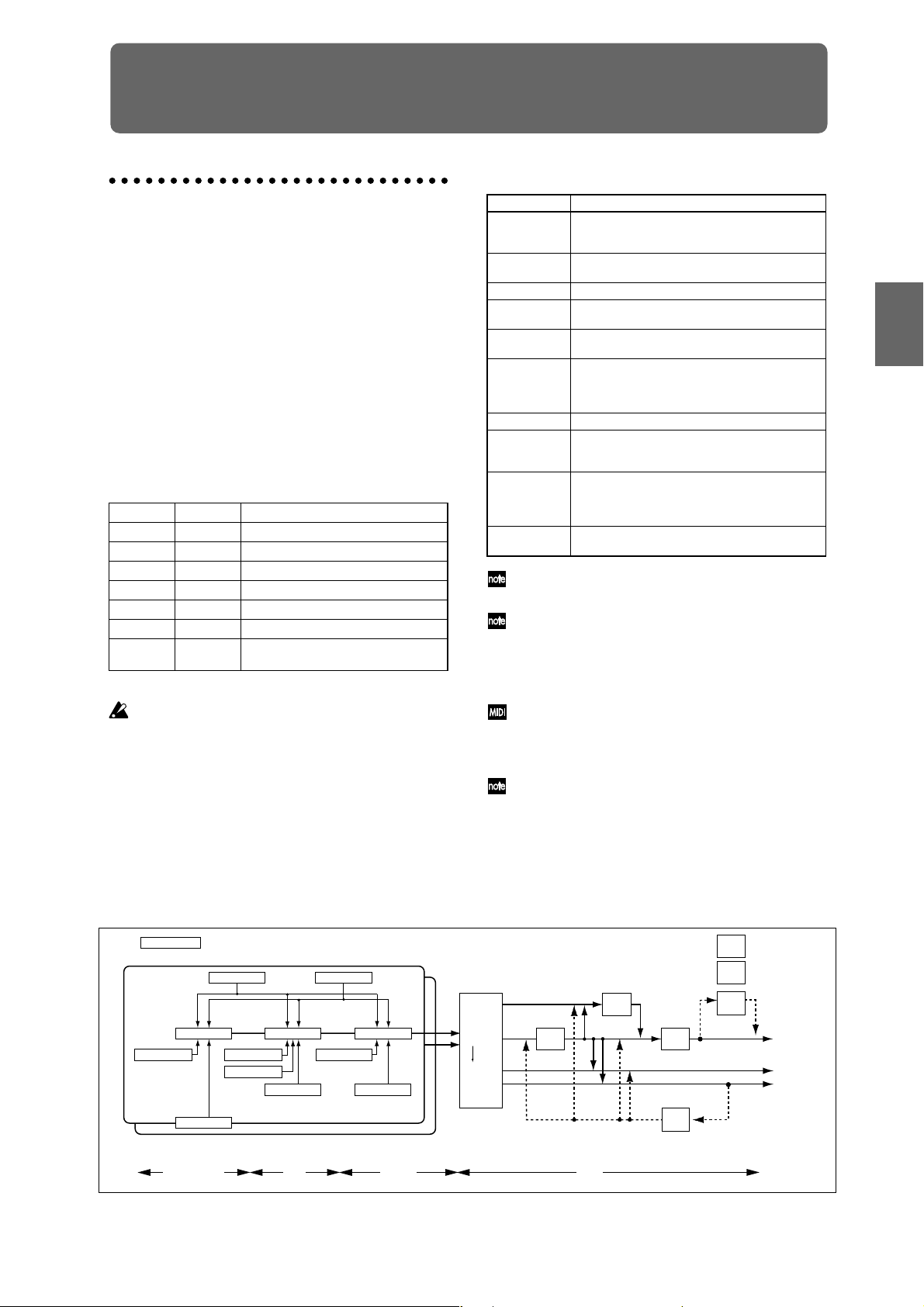
Playing and editing programs
OSC Basic : P1 - 2,3
Filter1(A/B) : P3 - 1
Amp1 Level/Pan : P4 - 1
Pitch EG : P2 - 3
Filter1 EG : P3 - 4
Amp1 EG : P4 - 3
OSC1 LFO1 : P5 - 1
OSC 1
OSC 2
Filter1 Mod. : P3 - 2
Filter1 LFO Mod. : P3 - 3
OSC1 Pitch Mod. : P2 - 1
OSC1 LFO2 : P5 - 2
Amp1 Mod. : P4 - 2
Program Basic : P1 - 1
AUDIO OUTPUT
L/MONO, R
Master
Effect
1, 2 : P9
Master
EQ : P9
Insert
Effect
1 ... 5 : P8
Oscillator / Pitch
Filter
Amplifier
Effect
Controller
Setup:
P1 - 4
Arpeggiator : P7
OSC1,2
Insert Effect
Master Effect
Individual Output
Routing : P8-1
P1–1 and P2–2 etc. indicate the page tab screens used when editing on the TRITON Exterme.
AUDIO OUTPUT
INDIVIDUAL
3, 4
1, 2
Valve
Force
: P9
Placement:
Insert(Use Indiv.3/4 BUS)
Valve
Force
: P9
Placement:
Final
(Program Mode)
Program structure
When the TRITON Extreme is shipped from the factory, it
contains 1,344 programs (excluding the GM2 variation
programs). You can create your own original programs by
editing these factory-set programs, or by initializing a program and starting “from scratch.” You can also create programs using RAM multisamples that you have sampled
or loaded in Media mode. In addition, you can play a program and resample your performance, or sample an external audio source while listening to the sound of a
program.
Each of the rewritable banks A–E and H–N contain 128
programs (total 1,536). There are also non-rewritable bank
G (GM2 capital programs), banks g(1)–g(9) (variation programs), and bank g(d) (drums). When shipped, banks A–
D and H–N contain preloaded programs.
Program banks
Bank Prog. No. Explanation
A...D, H...M 000...127 Preloaded programs
E 000...127 User (initial) programs
F 000...127 MOSS programs
G 001...128 GM2 capital programs
g(1)...g(9) (☞VNL) GM2 variation programs
g(d) (☞VNL) GM2 drum programs
N 000...127 Preloaded programs,
user (initial) programs
☞ For details on the factory-set programs, refer to “VNL.”
You can select programs from bank F only if the EXBMOSS option is installed.
P0: Play is where you select and play programs, make
simple adjustments using the Performance Editor, and
adjust the arpeggiator settings.
In the P1: Edit-Basic–P9: Edit-Master Effect pages you can
modify the sound by editing the various parameters of the
program you selected in P0: Play.
Program mode page structure
Page Explanation
P0: Play
Select programs, use the Performance Editor to perform easy editing, select and make settings for
arpeggio patterns, make settings for sampling.
P1: Edit-Basic Set basic program parameters such as oscillator
and multisample. Set scale and controllers.
P2: Edit-Pitch Settings related to the pitch, including the pitch EG.
P3: Edit-Filter Settings related to the filter (tone), including the fil-
ter EG.
P4: Edit-Amp Settings related to the amplifier (volume), including
amp EG and pan.
P5: Edit-
Common
LFO
For each of the two LFO’s pro vided for each oscilla-
tor, select the LFO type and speed, etc. (Settings in
the pitch, filter, and amp pages will determine how
deeply the LFO that you specify here is applied.)
P6: --P7: Edit-
Arpeggiator
P8: Edit-Insert
Effect
Settings for the arpeggiator. (Some of these are
shared with the arpeggiator settings of P0, and you
may edit them in either location.)
Select insert effects and make settings for them.
Specify the oscillator routing (send levels to the
insert effects, master effects, and independent out-
puts), make settings for Valve Force.
P9:
Edit-Master
Effect
Select master effects and make settings for them.
Make settings for the master EQ and Valve Force.
For details on how to access each mode and page,
refer to “Basic operation” (☞p.13).
Bank F is available only if the EXB-MOSS option is
installed. The page structure and parameter structure
of bank F programs are different than for the programs of other banks. Refer to the EXB-MOSS
owner’s manual.
All transmission and reception of MIDI data in Program mode is performed on the global MIDI channel.
The global MIDI channel is set in Global P1: MIDI
“MIDI Channel.”
You can perform sampling/resampling in Program
mode (☞p.80, QS p.22). You can also apply the TRITON Extreme’s effects to an external audio input, for
a wide range of possibilities. (☞p.107, 111)
Program
Combination
SequencerSamplingSong PlayGlobalEffectMedia, etcPresetOther
Program structure and corresponding pages
19
Page 24
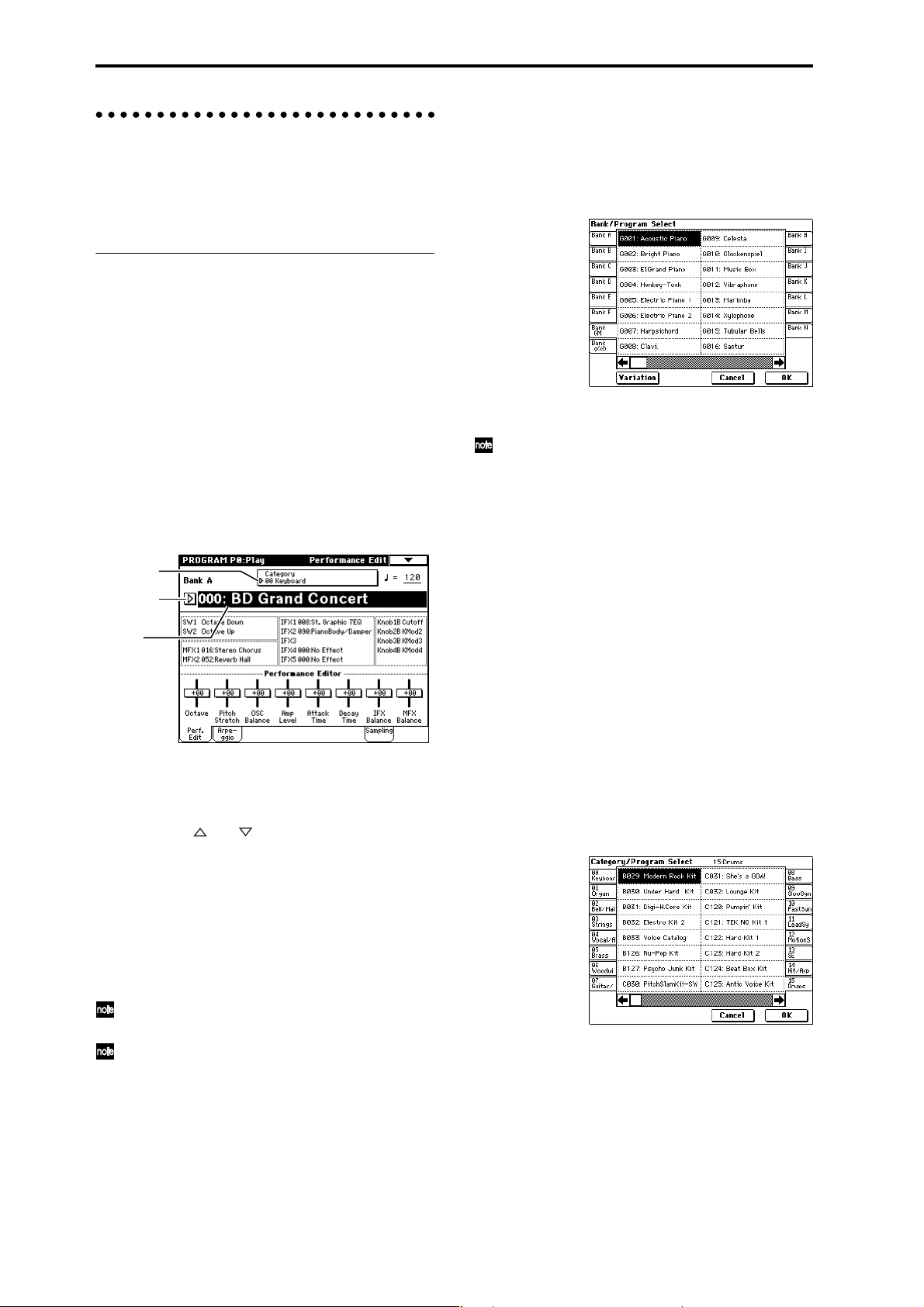
Playing a program P0: Play
Here you can select and play programs. You can use the
Performance Editor to make simple edits, and also make
settings for the arpeggiator, external audio input, and
sampling.
Selecting a program
There are three ways to select a program. For the procedure, refer to the appropriate page.
• Using the controls of the TRITON Extreme
Selecting by bank/program number
Selecting by program category
Selecting by using 10’s Hold
• Using a connected switch
• Receiving MIDI program change messages
Selecting a program on the TRITON Extreme
Selecting by bank/program number
1 Make sure that “Program Select” is selected.
If it is not selected, access the PROGRAM P0: Play page
and press the “Program Select” area to highlight it.
Category
popup button
Program
Select popup
button
Program
Select
2 Use the VALUE controllers to select the program
number that you wish to play.
You can use the following methods to select a program.
• Turn the [VALUE] dial.
• Press the [ ] or [ ] key.
• Use numeric keys [0]–[9] to specify the number,
and press the [ENTER] key.
3 Press a BANK [A]–[N] key to switch banks.
By switching banks you can access programs in different banks. (The key will light, and the selected bank
will appear in the left side of the LCD screen.)
For example to select bank B, press the BANK [B] key.
(The [B] key will light, and an indication of Bank B will
appear in the upper left of the LCD screen.)
The [F] key is only available if the EXB-MOSS option
is installed.
Each time the [G] key is pressed, it will advance to the
next GM bank in the following order:
G→g(1)→g(2)→g(3)→g(4)→(5)→g(6)→g(7)→g(8)
→g(9)→g(d)→G ... (The LED will light, and an indication of Bank G, g(1)–g(9), or g(d) will appear in the
upper left of the LCD screen.)
Selecting by bank
You can select programs from a list organized by program
bank.
1 Press the “Program Select” popup button.
A tabbed “Bank/Program Select” popup menu will
appear.
In the illustration above, bank G is selected. The center
area shows the programs contained in that bank.
The Variation button will be displayed only when
bank G is selected. Each time you press this button,
the bank will change in the following order:
G→g(1)→g(2)...g(8)→g(9)→G...
2 Press the tabs located to the left and right sides of the
display to select a bank.
3 Press one of the program names in the center area to
select a program.
The selected program will be highlighted.
4 When you are satisfied with the selected program,
press the OK button to close the popup menu.
If you press the Cancel button, the selection you made
here will be discarded, and you will return to the program that had been selected before you opened the
popup menu.
Selecting by category
You can select programs from within a category, such as
keyboard, organ, bass, and drums. When shipped from
the factory, the preloaded programs are organized into
sixteen categories.
1 Press the Category popup button.
A tabbed “Category/Program Select” popup menu
will appear.
In the illustration above, category 15: Drums is
selected. The center area shows the programs contained in that category.
2 Press the tabs located to the left and right sides of the
display to select a different category.
The name of the selected category will be displayed in
full in the upper right.
3 Press one of the program names in the center area to
select a program.
The selected program will be highlighted.
20
Page 25
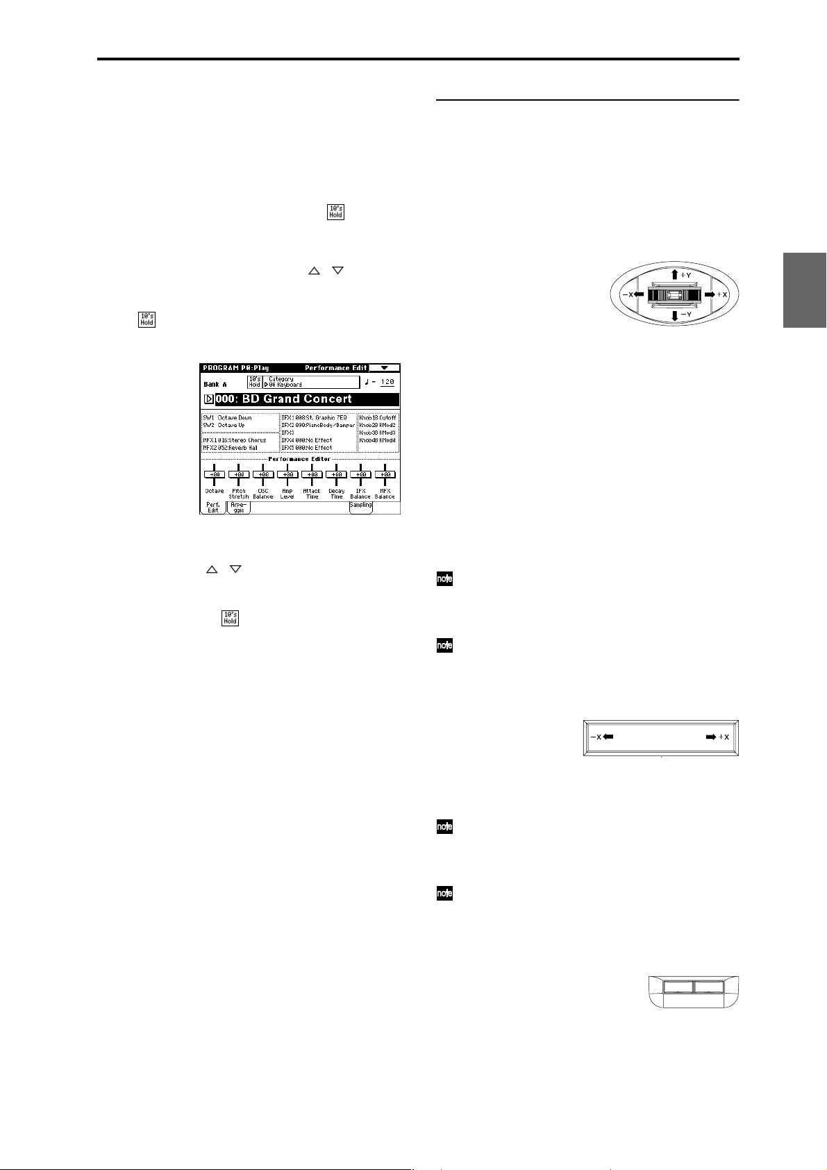
4 When you are satisfied with the selected program,
press the OK button to close the popup menu.
If you press the Cancel button, your selection will be
discarded, and you will return to the program that had
been selected when you opened the popup menu.
Using 10’s HOLD when selecting programs
If you press the [./10’s HOLD] key to turn on the 10’s
Hold function (the LCD screen will indicate ), the ten’s
place of the program number will be fixed, and you will
be able to switch programs simply by pressing a single
numeric key . Each time you press a numeric key, the one’s
place will change. You can also use the [ ][ ] keys to
change the value of the ten’s place.
1 Press the [./10’s HOLD] key to make the display indi-
cate .
The ten’s place of the program number will be held
(fixed).
2 By pressing a numeric key [0]–[9], you can input the
one’s place in a single action.
3 You can use the [ ][ ] keys to change the value of
ten’s place.
4 To cancel the 10’s HOLD function, press [./10’s
HOLD] to erase the
display.
Using a footswitch to select programs
You can assign the Program Up/Down function to an on/
off type foot switch (such as the optional PS-1) connected
to the rear panel ASSIGNABLE SWITCH jack, and use it
to switch combinations. (☞p.90)
Using controllers to modify the sound
The TRITON Extreme provides various controllers – a joystick, the ribbon controller, the SW1 and SW2 switches,
and the REALTIME CONTROL [1], [2], [3], [4] knobs –
that let you modify the tone, pitch, volume, or effects in
realtime while you play.
You can use these controllers to modify the sound while
you are playing a program.
Joystick
JS(+X): Move the joystick toward the right to apply an
effect.
Normally this is used to control the pitch (bend
up).
JS(–X): Move the joystick toward the left to apply an
effect.
Normally this is used to control the pitch (bend
down).
JS(+Y): Move the joystick away from yourself to apply
an effect.
Normally this is used to control the oscillator
LFO (vibrato).
JS(–Y): Move the joystick toward yourself to apply an
effect.
Normally this is used to control filter LFO (wah).
You can use the Lock function of [SW1] or [SW2] keys
to hold the effect in the current position of the joystick. For the procedure, refer to “The lock function”
on the following page.
You can use the joystick as a source for alternate modulation or effect dynamic modulation, to control program parameters or effect parameters.
Ribbon controller
Program
Combination
SequencerSamplingSong PlayGlobalEffectMedia, etcPresetOther
Selecting programs from a MIDI device
MIDI program change messages can be transmitted from
an external MIDI device, and received by TRITON
Extreme to select programs.(☞PG p.290)
0
Move your finger to the left and right on the ribbon controller to apply an effect.
Normally, this is used to control pitch, volume or filter etc.
You can use the Lock function of [SW1] or [SW2] keys
to hold the effect even after you release your finger
from the ribbon controller . For the pr ocedur e, refer to
“The Lock function” on the following page.
You can use the ribbon controller as a source for alternate modulation or effect dynamic modulation, to
control program parameters or effect parameters.
SW1, SW2
SW 1 SW 2
You can use these keys as sources for alternate modulation
or effect dynamic modulation to control program parameters or effect parameters.
These switches can also be used to switch the octave, to
turn portamento on/off, or to lock the position of the ribbon controller or after touch lock function.
21
Page 26
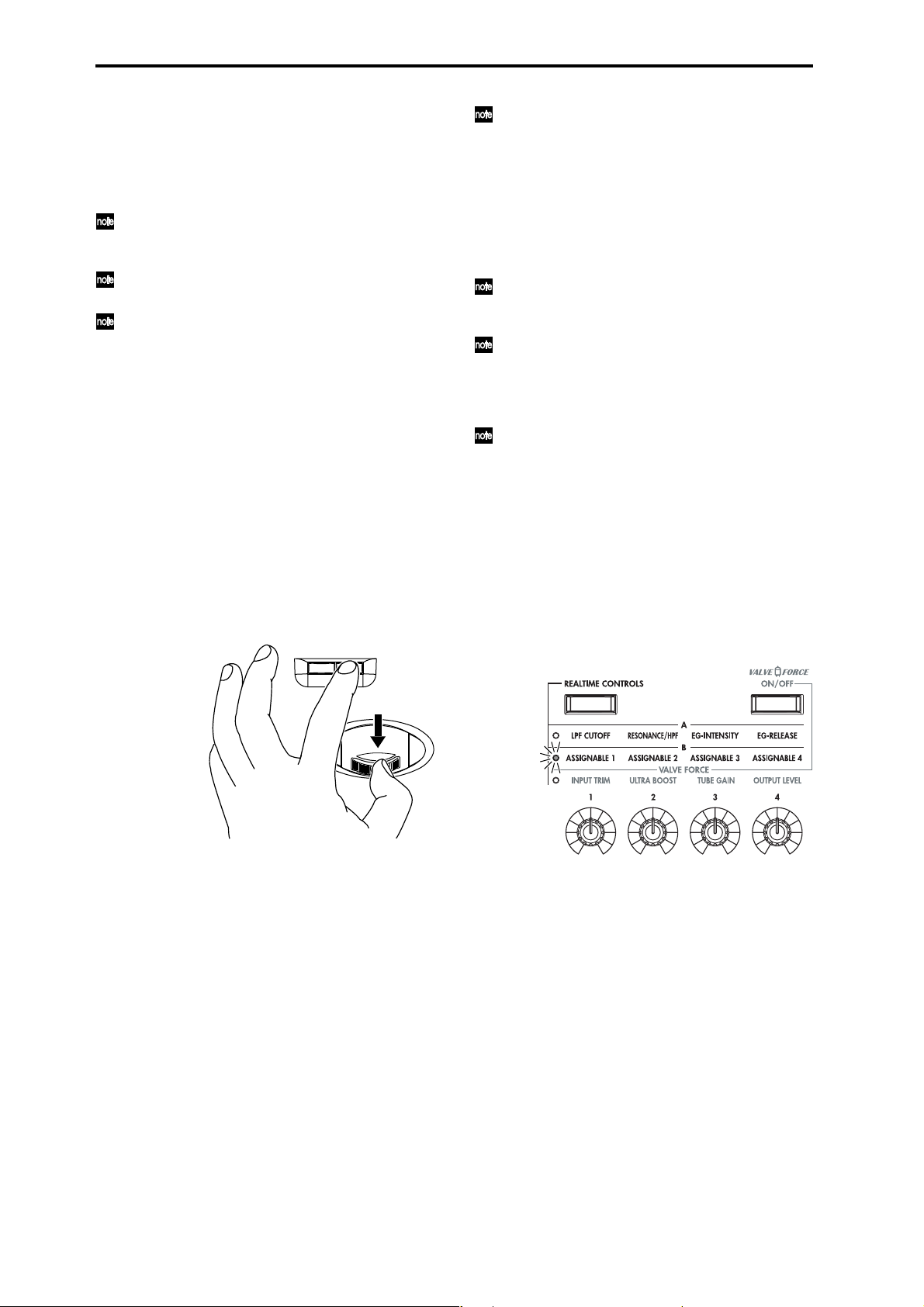
You can specify the way in which the [SW1] and [SW2]
keys will operate: either Toggle, when the assigned func-
tion will be switched between on and off each time the
key is pressed, or Momentary, when the assigned function
will be active on only as long as you hold down the
switch.
In Program mode, the function of the [SW1] and
[SW2] keys can be checked in the P0: Play, Performance Edit page.
When you write a program or combination, the on/
off status of the [SW1] and [SW2] keys is saved.
For details on making these settings, refer to “Setting
the function of [SW1] and [SW2]” (☞p.129).
Using the Lock function (examples)
Joystick
1 Select program bank J001: Acoustic Piano, and play
the keyboard.
To select a program, make sure that you are in Program
mode, and press the BANK [J] key, numeric key [1],
and then the [ENTER] key.
2 Move the joystick toward yourself (the –Y direction).
The modulation will deepen, and at the same time, resonance will be applied to give a unique character to the
sound.
3 While holding the joystick toward yourself, press the
[SW2] switch (The [SW2] key will light).
The modulation effect at this point will be maintained.
(Lock function)
SW 1 SW 2
In the LCD screen, SW2 indicates JS–Y & Ribbon
Lock. This means that the [SW2] key is assigned to
control the Lock function for the joystick –Y direction
and the ribbon controller (☞PG p.279). The key will
operate in Toggle mode.
If you move the joystick in the –Y direction, press the
[SW2] key to turn on the Lock function, then operate
the ribbon controller, and finally release both controllers, the sound you modified by the two controllers
will be maintained.
In many programs and combinations, the [SW2] key
is assigned to control the Lock function for the joystick –Y direction and the ribbon controller.
The Lock function can also be applied to aftertouch. If
the [SW1] or [SW2] switch is assigned to After Touch
Lock, the effect produced by pressing down on the
keyboard can be held by turning on the [SW1] or
[SW2] switch.
For details on the [SW1] and [SW2] switch functions,
refer to PG p.279.
REALTIME CONTROLS [1], [2], [3], [4]
These knobs can be used to control the filter cutoff frequency and resonance, the amp and filter EG, volume,
portamento time, pan, pitch LFO, or the send levels to the
master effects, etc. You can also use these knobs to control
the Valve Force parameters.
1 Press the [REALTIME CONTROLS] key to switch the
function of the realtime controllers.
Each time you press the key, A-mode, B-mode or Valve
Force will be alternately selected, and the corresponding LED will light.
4 Release the joystick, and play the keyboard.
The modulation will stay the same as it was when the
[SW2] key was pressed. Moving the joystick toward
yourself will not affect the sound.
5 Press the [SW2] key once again to release the Lock
function.
Ribbon controller
Make sure that the J001: Acoustic Piano program is
selected.
1 Press the [SW2] key. (The [SW2] key will light.)
2 Touch the ribbon controller, and move your finger to
left and right.
Movement in the +X direction will brighten the tone,
and movement in the –X direction will darken the tone.
3 Take your finger away from the ribbon controller.
The sound will remain as it was before you removed
your finger. (Lock function)
4 Press the [SW2] key once again to release the Lock
function.
22
2 Rotate the desired knob to control the sound, etc.
☞ For details about what is controlled, refer to QS p.6.
[VALUE] slider
When a program number is selected in Program P0: Play
page, or when a combination number is selected in Combination mode page P0: Play page, you can use the
[VALUE] slider as a source for alternate modulation or
effect dynamic modulation, and control program parameters or effect parameters.
Keyboard
Velocity
The force with which you initially strike a note can apply
an effect.
Normally this is used to control volume, or the speed or
sensitivity of the EG.
After Touch
This effect can be applied by varying the pressure on a key
that is already being held down.
Normally this is used to control volume, tone (cutoff frequency), or LFO sensitivity etc.
Page 27
Note Number
Varying amounts of an effect will be applied depending
on the position of the key on the keyboard.
Normally this is used to control volume, tone (cutoff frequency), LFO sensitivity, and EG sensitivity etc.
This can be used as a source for alternate modulation
or effect dynamic modulation, to control program
parameters or effect parameters.
Foot pedals/Switch
Damper Pedal
An optional switch-type damper pedal such as the Korg
DS-1H can be connected to TRITON Extreme. If a DS-1H
is connected, it will function as a half-damper pedal. The
half-damper function cannot be controlled by other pedals.
Assignable Foot Switch
If an optional foot switch such as the Korg PS-1 is connected to the rear panel ASSIGNABLE SWITCH jack, an
assigned function can be switched on/off using the foot
switch.
The function of the foot switch is assigned in Global P2:
Controller “Foot Switch Assign” (☞p.90).
Assignable Foot Pedal
An optional expression pedal such as the Korg EXP-2 foot
controller or Korg XVP-10 EXP/VOL pedal can be connected to the rear panel ASSIGNABLE PEDAL jack, and
used to apply an effect.
The function of the foot pedal is assigned in Global P2:
Controller “Foot Pedal Assign” (☞p.90).
Easy program editing
Performance Edit (the Performance Edit tab)
You can use the eight Performance Editor sliders to make
overall adjustments to the major parameters of Program
P1–9.
☞ For details on what is controlled, refer to QS p.6 or PG
p.2.
REALTIME CONTROLS [1], [2], [3], [4]
☞ For details on what is controlled, refer to QS p.6.
Easy arpeggiator editing
Program editing
You can edit the preloaded programs (banks A–D, H–N)
that the TRITON Extreme is shipped with, or you can start
with an initialized program (banks E, N) to create an original program.
The P0: Play page lets you perform basic editing, but more
detailed editing can be done in the P1: Edit-Basic–P9: EditMaster Effect pages.
If you wish to save an edited program into internal
memory, be sure to Write the program. (☞p.114)
You can write programs to the 1,536 program memory areas (internal memory) of banks A–E and H–N.
You can also save and manage programs on various
types of media. (☞p.117)
The P1: Edit-Basic–P5: Edit Common LFO parameters
are shared by oscillators 1 and 2, and can be copied
using the page menu command “Copy Oscillator.”
This command is useful when you want to set both
oscillators to the same settings, or when you want to
copy settings from a different program.
The three elements of sound
Sound can be broken down into three elements: pitch,
tone, and volume.
On TRITON Extreme, these elements correspond to the
Pitch, Filter, and Amplifier settings of a program. In other
words you would adjust the Pitch settings to modify the
pitch, the Filter settings to modify the tone, and the
Amplifier settings to modify the volume.
In Oscillator (Oscillator: P1: Edit-Basic settings) you
select the waveform multisample that determines the
basic sound, and specify its pitch. This sound is then modified by the pitch settings (Pitch: P2: Edit-Pitch), filter set-
tings (Filter: P3: Edit-Filter), and amp settings (Amplifier:
P4: Edit-Amp) to create the basic sound of the program.
This basic sound can then be modified further by using
the insert effects (P8: Edit-Insert Effect settings), master
effects, master EQ, and Valve Force (P9: Edit-Master
Effect settings) to apply finishing touches.
When arpeggiator settings (P7: Edit-Arpeggiator.) and
controller settings (P1: Edit: Basic, Control Setup) are
added to this, the final result is called a “program.”
Program
Combination
SequencerSamplingSong PlayGlobalEffectMedia, etcPresetOther
Arpeggio tab
Here you can select the arpeggio pattern, and make realtime adjustments to the arpeggio parameters while you
perform.
ARPEGGIA TOR [ON/OFF] key, [TEMPO] knob, [GA TE]
knob, [VELOCITY] knob
Use the ARPEGGIATOR [ON/OFF] key to turn the arpeggiator on/off.
The ARPEGGIA TOR [TEMPO], [GATE], and [VELOCITY]
knobs control the tempo, duration, and strength of the
arpeggiated notes.
The Compare function
When P1–P9 are selected, pressing the [COMPARE] key
(the key will light) will recall the sound as it was written
before you edited it.
Pressing [COMPARE] again (the light goes dark) returns
you to the version you are editing.
If you edit while the [COMPARE] key is lit, the key will
again go dark and your previous unsaved edits will be
lost.
23
Page 28
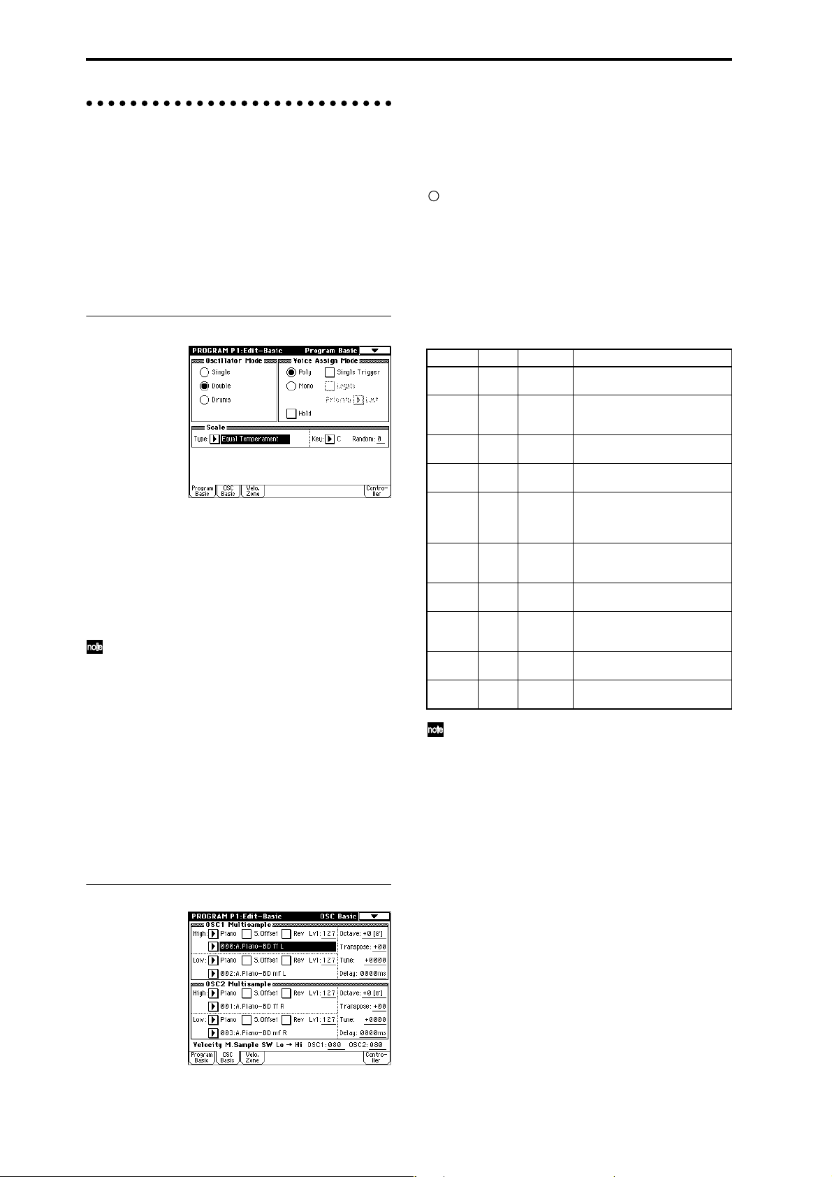
Oscillator settings P1: Edit-Basic
Basic settings for the oscillator are made in the P1: EditBasic page. The TRITON Extreme provides two oscillators, and for each oscillator you can select a basic waveform (“multisample”) and set the pitch.
The multisamples provided by the TRITON Extreme
include waveforms for musical instruments such as
pianos, as well as special waveforms unique to synthesizers. Multisamples reproduce the complex overtone structure and frequency characteristics that allow us to identify
a sound as being “piano-like” or “guitar-like” etc..
Program Basic page
Oscillator Mode
This sets the mode of the oscillator. Single uses one oscillator and Double uses two oscillators. In the case of Sin-
gle the maximum polyphony is 60 notes, and in the case
of Double the maximum polyphony is 30 notes. If you
wish to use a Drum Kit to create a drums program, select
Drums. In the case of Drums, the polyphony is normally
60 notes.
Depending on the multisamples that are selected for
each oscillator, the maximum polyphony can be up to
120 notes for Single, up to 60 notes for Double, and
up to 120 notes for Drums. (☞p.12)
Voice Assign Mode
Select whether the program will sound in Poly (polyphon-
ically) or Mono (monophonically). If this is set to Poly,
you will be able to play chords using the program. If this
is set to Mono, only one note will sound even if you play a
chord. Normally you will set this to Poly, but it is effective
to use Mono when you are playing sounds such as a solo
instrument, an analog-synth bass or a synth lead. Try
switching between Poly and Mono, and listen to the
results.
OSC Basic page
In this page you can select the multisample for each oscillator. The TRITON Extreme contains 962 different multisamples. (☞VNL)
24
Data sampled on the TRITON Extreme can also be used as
a multisample.
Selecting a multisample
The multisample will determine the basic character of the
program.
Use “High MS Bank” to select the multisample bank,
and use “High Multisample” to select the multisample.
You can select preset multisamples if “High MS Bank”
is set to other than RAM.
If “High MS Bank” is RAM, you can select multisamples that were sampled on the TRITON Extreme or
loaded in from media. Select from 000–999 for “High
multisample.”
Multisample bank
MS Bank Mbyte No. Explanation
ROM32000–424 TRITON Classic preset multisam-
ples
RAM 96 000–999 RAM multisamples (created in
Sampling mode or loaded in Media
mode)
Piano 16 000–003 Preset multisamples for stereo
piano
New1 16 000–007 Preset multisamples for stereo
piano and choir
New2 16 000–048 Preset multisamples for organ,
solo brass, electric guitar, acoustic guitar, electric bass, acoustic
bass, etc.
Best 16 000–046 Preset multisamples for electric
piano, clavi, brass, woodwinds,
choir, drums, etc.
OrchS 16 000–112 Preset multisamples for orchestral
strings
OrchB 16 000–079 Preset multisamples for orchestral
brass, woodwinds, percussion,
and harp etc.
Vint 16 000–157 Preset multisamples for vintage
analog synths
Synth 16 000–077 Preset multisamples for house and
trance music
If “High MS Bank” is set to ROM, pressing the “High
Multisample” popup button will display all internal
ROM multisamples, organized into 15 categories. Use
the tabs located at the left and right to select the
desired category, and select a multisample from
within that category.
High Multisample and Low Multisample
If you specify a High and Low multisample for an oscillator, either the High or the Low multisample will sound
depending on the velocity of the note (i.e., the strength at
which you play the keyboard). This function is called
velocity multisample switching.
1 Specify different multisamples for “High Multisam-
ple” and “Low Multisample.”
2 Specify a velocity value for “Velocity M.Sample SW
Lo→Hi.”
Notes played on the keyboard at a velocity less than
the value you specify will sound the Low multisample;
velocities at or above this velocity value will sound the
High multisample.
For example if you set “Velocity M.Sample SW
Lo→Hi” to 100, playing the keyboard softly will sound
the “Low multisample,” and playing strongly will
sound the “High multisample.”
Page 29
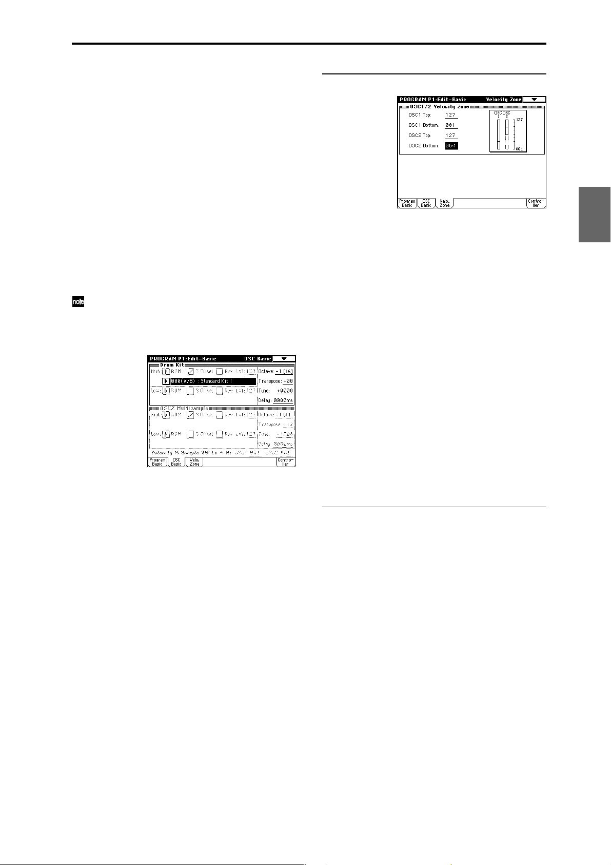
3 Adjust the “Lvl” (Level) for High and Low multisam-
ples to set their volume balance.
If you do not wish to use this function, set the “Velocity M.Sample SW Lo→ Hi” value to 001. Only the
High multisample will sound.
Rev (Reverse) check box
If this is checked, the multisample will be played backward. This can produce interesting results when used on
sound-effects, etc. Normally you will not check this.
● When “Oscillator Mode” = Double
To use OSC2, set “Oscillator Mode” to Double in the Program Basic page.
In the same way as for OSC1, you can set High and Low
multisamples for OSC2.
The playback pitch can be set independently. By using the
same multisample with slightly different “Tune” settings,
you can “detune” the oscillators to produce a richer
sound.
It will be convenient to use the page menu command
“Copy Oscillator” to make the oscillator settings
match each other.
● When “Oscillator Mode” = Drums
In the Program Basic page, set “Oscillator Mode” to
Drums. When this is set to Drums, you will be able to cre-
ate a drum program.
This will select a drum kit instead of a multisample. TRITON Extreme provides 50 factory preset drum kits that
are suitable for a wide variety of music. (☞VNL)
Here you can only select a drum kit. To edit or create a
drum kit, use Global P5: Drum Kit (☞p.92).
Velocity Zone page
Here you can specify the range of velocities for each oscillator. In the example shown above, the velocity ranges are
as follows.
• OSC1 will sound at all velocity values.
• OSC2 will sound only on strongly played notes (64
and above).
• You can use Velocity Multisample Switching in
addition to this parameter (☞“High Multisample, Low
Multisample”). For this example, set “OSC1” in
“Velocity M.Sample SW Lo→Hi” to 032 and “OSC2”
to 096. The settings are shown as vertical lines in the
velocity zone display.
In this example, the multisamples will sound over four
levels.
Velocity values 001–031: sounds only the OSC1 Low
multisample.
Velocity values 032–063: sounds only the OSC1 High
multisample.
Velocity values 064–095: sounds the OSC1 High multi-
sample and the OSC2 Low
multisample.
Velocity values 096–127: sounds the OSC1 High multi-
sample and the OSC2 High
multisample.
Controller Setup page
For each program, this tab lets you make settings for the
[SW1] and [SW2] key, and for the B-mode of REALTIME
CONTROLS knobs [1]–[4] (☞p.129, PG p.14, 279, 280)
Program
Combination
SequencerSamplingSong PlayGlobalEffectMedia, etcPresetOther
The following multisamples or drum kits can be used
for the oscillator.
• Preset multisamples (see the table on the preceding
page)
• Multisamples that you sampled (RAM)
(Programs can be created from multisamples/samples
that you sampled in Sampling mode etc. or loaded
from media in Media mode.)
• Nine internal drum kits (ROM)
• 144 user drum kits created in Global mode
(Drum samples can be freely assigned to each key to
create a drum kit. For the sound of each key, you can
make filter and amp settings, and specify routing to the
effects and to the individual audio outputs.)
25
Page 30
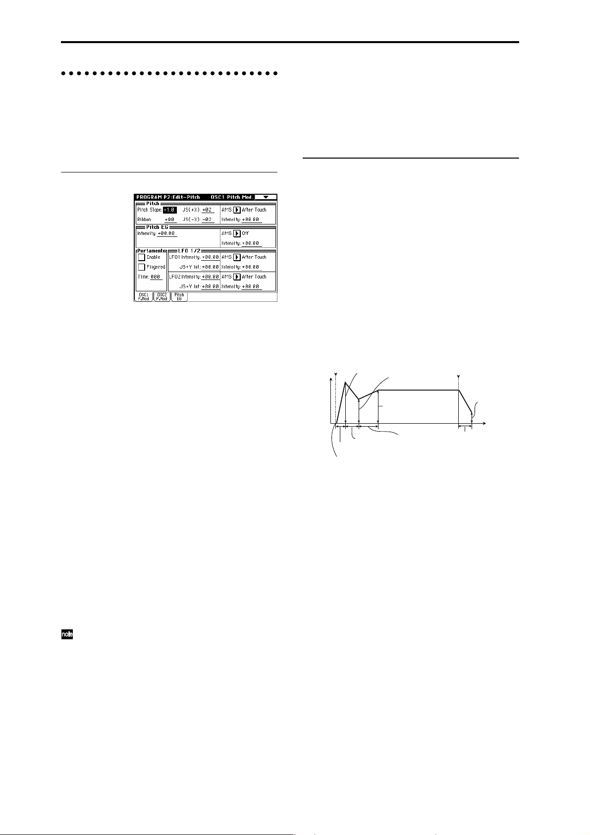
Pitch settings P2: Edit-Pitch
Here you can specify how the pitch of the multisample
assigned to each oscillator will change. Pitch EG and LFO
settings allow the pitch to varied over time. The OSC1
P.Mod page is valid when “Oscillator Mode” is set to Sin-
gle or Drums.
OSC1 Pitch Mod. page
Pitch
The “JS (+X)” and “JS(–X)” settings specify the amount of
pitch change (in semitones) that will occur when MIDI
pitch bend messages are received or when the joystick is
moved to left or right. A setting of +12 allows the pitch to
be controlled a maximum of one octave upward; a setting
of –12 allows the pitch to be controlled a maximum of one
octave downward.
“Ribbon” specifies the amount of pitch change (in semitones) that will occur when MIDI control change (CC) #16
messages are received or when the ribbon controller of a
TRITON Extreme or other MIDI-connected instrument is
moved to left or right. With a setting of +12, the pitch will
be raised one octave at the far right of the ribbon controller, and will be lowered by one octave at the far left of the
ribbon controller.
Pitch EG
When the “Intensity” value is set to +12.00, the pitch EG
specified in the Pitch EG page will produce a maximum of
±1 octave of pitch change.
Portamento
If “Enable” is checked, portamento will be applied.
Portamento makes the pitch change smoothly when you
play the next note before releasing the previous note.
The “Time” parameter specifies the portamento time. As
this value is increased, the pitch will change over a longer
time. With a value of 000, there will be no portamento.
If Porta.SW CC#65 is assigned as the function of
[SW1] or [SW2] key, the portamento effect can be
switched on/off by [SW1] or [SW2] key.
“Intensity (AMS Intensity)” specifies the depth of vibrato
that will be applied by the LFO when an AMS (Alternate
Modulation Source) is used. For example if “AMS (LFO1
AMS)” is set to After Touch and you set an appropriate
value for “Intensity (AMS Intensity),” vibrato will be
applied when you apply pressure to the keyboard or
when MIDI aftertouch messages are received.
Pitch EG page
Here you can adjust the settings for the pitch EG.
When you wish to create sound effects etc., set the pitch
EG to make major changes in pitch over time.
To realistically simulate the slight change in pitch that
occurs when a string is plucked or at the attack of a brass
or vocal sound, you can use the EG to create a subtle
change in pitch at the attack (☞PG p.16).
● EG and LFO
By using an EG (envelope generator) to apply time-varying change or by using an LFO (Low Frequency Oscillator) to apply cyclic change to pitch, filter, or amp, you can
create changes in the pitch, tone, or volume.
EG (Envelope Generator)
TRITON Extreme provides a Pitch EG, Filter EG, and
Amplifier EG, which produce time-varying changes in
pitch, tone, and volume respectively.
Attack Level
note-on note-off
Level
Decay Time
Attack Time
Start Level
LFO (Low Frequency Oscillator)
For each oscillator, TRITON Extreme provides two LFO’s
that can be used to apply cyclical change in pitch, tone,
and volume.
Examples of this are vibrato (cyclical change in pitch),
wah (cyclical change in tone), and tremolo or auto-pan
(cyclical change in volume).
Break Level
Sustain Level
Slope Time
Release Time
Release Level
Time
LFO 1/2
An LFO can be used to cyclically modulate the pitch (a
“vibrato” effect).
“LFO 1/2 Intensity” sets the depth to which the LFO spec-
ified in P5: Edit-Common LFO will affect the pitch. With a
setting of +12.00, vibrato will produce a maximum of ±1
octave of pitch change.
“JS+Y Int” specifies the amount of vibrato that the LFO
will produce when the joystick is pushed away from yourself.
26
Page 31

Filter settings P3: Edit-Filter
The filter allows you to diminish or emphasize specified
frequency areas of the multisample selected for the oscillator.
The tone of the sound will depend significantly on the
filter settings.
TRITON Extreme provides Filter 1 for OSC1 and Filter 2
for OSC2. For each of these filters, you can select from two
types (Low Pass Resonance or Low Pass & High Pass).
Filter 2 can be used if “Oscillator Mode” is set to Double.
Level
Filter1 page
Overtones included
in the original multisample
Frequency (pitch)
Level
Filter
Filter characteristics
This area of
overtones will
be diminished
Overtones after
passing through
the filter
Frequency (pitch)
High pass filter
This type of filter allows the high frequency range to pass
and cuts the low frequency range. Use this when you wish
to make the sound thinner. However if the cutoff frequency (Frequency) is raised excessively high, the volume
will become very low.
High Pass
Level
12dB/oct
Frequency
Resonance
When “Resonance” is set to a higher value, the overtones
in the region of the cutoff frequency will be boosted as
shown in the diagram below, giving a distinctive character to the sound.
When resonance is applied
Low Pass
Level
Program
Combination
Filter Type, Filter A, Filter B
Selects the type of filter, and specify the “Frequency” (cutoff frequency) and “Resonance” (resonance level).
• Low Pass Resonance (24 dB/oct low pass filter with
resonance): Make settings for filter A.
• Low Pass & High Pass (12 dB/oct low pass filter and
12 dB/oct high pass filter in series connection): Make
low pass filter settings in filter A, and high pass filter
settings in filter B.
● Filter Type
Low pass filter
This is the most common type of filter, which allows the
low frequency range to pass and cuts the high frequency
range. When the overtones of the high range are cut, a
bright sound will become darker (more mellow).
24 dB/oct and 12 dB/oct refer to the steepness of the cut.
24 dB/oct means that the gain will decrease 24 dB in one
octave (i.e., as the frequency doubles). A 12 dB/oct filter
would decrease the gain 12 dB in one octave. The 24 dB/
oct filter produces a steeper cut.
Low Pass
Level
12dB/oct
24dB/oct
Frequency
Low resonance value High resonance value
Filter1 Mod. page
Controllers and the filter EG can be used to modulate the
filter cutoff frequency that was specified in the Filter1
page. By using a controller to vary the tone or by using an
EG to create time-varying changes, you can add a rich
variety of tonal change to the sound.
Keyboard Track
This varies the cutoff frequency according to the position
of the key on the keyboard that you play.
• When “Ramp Low” is set to a positive (+) value, the
cutoff frequency will rise as you play lower on the
keyboard, making the sound brighter. When set to a
negative (–) value, the cutoff frequency will fall as you
play lower on the keyboard, making the sound darker.
• When “Ramp High” is set to a positive (+) value, the
cutoff frequency will rise as you play higher on the
keyboard, making the sound brighter. When set to a
negative (–) value, the cutoff frequency will fall as you
play higher on the keyboard, making the sound
darker.
•“Intensity to A” and “Intensity to B” adjust the effect
that keyboard tracking will have on filters A and B
(☞PG p.18).
SequencerSamplingSong PlayGlobalEffectMedia, etcPresetOther
27
Page 32

Filter EG
Adjusts the effect produced by the filter EG, whose settings are made in the EG page.
• Use the “Velocity to A” and “Velocity to B” settings to
specify the effect of velocity on the filter EG.
• Use the “Intensity to A” and “Intensity to B” settings
to specify the depth of the filter EG.
•“Into A (AMS Int. to A)” and “Into B (AMS Int. to
B)” adjust the effect that AMS will have on the filter
EG depth.
These three settings will determine the depth of the
tonal change produced by the filter EG.
Filter A/B Modulation
Set this when you wish to produce tonal change by using
controllers etc. to vary the cutoff frequency.
Filter1 LFO Mod. page
Indicates settings that allow the LFO to produce cyclic
changes in tone (a “wah” effect).
“Intensity to A (LFO Int. to A)” and “Intensity to B (LFO
Int. to B)” specify by how much the LFO will change the
tone.
“JS-Y Intensity to A” and “JS-Y Intensity to B” specify
the depth of the wah effect that will be produced by the
LFO when the joystick of TRITON Extreme is moved
toward yourself, or when CC#2 is received.
“Intensity to A (LFO1 AMS Int.to A)” and “Intensity to B
(LFO1 AMS Int. to B)” specify the depth of the wah effect
that will be produced by the LFO when “AMS (LFO1
AMS)” is used. For example if “AMS (LFO1 AMS)” is set
to After Touch, applying pressure to the keyboard of the
TRITON Extreme, will produce a wah effect.
Amplifier settings P4: Edit-Amp
These settings affect the volume. Here you can adjust the
way in which the Amp EG and LFO produce time-varying
and cyclic changes in volume, and how the controllers etc.
will affect the volume.
Amp1 applies to OSC1, and Amp2 applies to OSC2.
Amp2 can be used if “Oscillator Mode” is set to Double.
For example, the volume of a piano note begins at a high
volume the instant you play the note, and then decreases
gradually. The volume of an organ note remains constant
as long as you continue pressing the key. The volume of a
note on a violin or wind instrument can be varied during
the note by the musician (i.e., by regulating the amount of
pressure on the bow or the force of the breath).
Volume
Piano
Volume decays gradually
Time
Amp1 Level/Pan page
Volume
Organ
Volume remains constant
until note is released
Time
Filter1 EG page
Indicates settings for the filter EG, which controls timevariant changes in tone. Make settings for the EG here,
and set the depth of its effect in the Filter1 Mod. page Fil-
ter EG parameter (☞PG p.20).
● Filter EG and Amplifier EG
When the Filter EG changes the cutoff frequency, the tone
will change. However depending on the volume changes
produced by the Amplifier EG, this can be heard in different ways. For example by changing the speed at which the
tone and volume begin (attack) or decay, you can significantly vary the character of the tonal change. It is a good
idea to adjust the changes of both the Filter EG (tone) and
the Amplifier EG (volume) as you proceed with editing.
(☞“Amp1 EG page”)
28
Amp Level
Adjusts the volume of the sound that has passed through
the oscillator, filter, and amp.
Pan
Specifies the pan (stereo position) after the signal has
passed through the oscillator, filter, and amp. Normally
you will set this to C064. If “Oscillator Mode” is Double
and you wish to create a sense of stereo, set the Amp1
Level/Pan page and Amp2 Level/Pan page parameter
“Pan” to left and right for oscillators 1 and 2 respectively.
With a setting of Random, the pan will change randomly
each time you play a note on TRITON Extreme, producing
an interesting effect.
AMS (Pan AMS), Intensity
“Intensity” specifies the depth of the panning effect that
will occur when “AMS (Pan AMS)” is in use.
If you set “AMS (Pan AMS)” to Note Number, the pan
will change according to the keyboard position at which
you play a note on a TRITON Extreme. With a setting of
LFO1 or 2, the sound will sweep from side to side (auto
pan). Other settings allow you to move the oscillator pan
by operating a controller.
Use DKit Setting
This is valid when “Oscillator Mode” is set to Drums. If
this is checked, the pan location specified by the Drum Kit
for each drum sound will be used. If this is unchecked, all
drum sounds will sound at the same location. Preload and
GM drum kits are set to stereo settings. Normally you will
leave this checked.
Page 33

Amp1 Mod. page
Piano
Organ
Strings
Keyboard Track
This lets you vary the volume relative to the position of
the key you are playing on the keyboard.
• When “Ramp Low” has a positive (+) value, the vol-
ume will increase as you play lower on the keyboard.
With a negative (–) value, the volume will decrease as
you play lower on the keyboard.
• When “Ramp High” has a positive (+) value, the vol-
ume will increase as you play higher on the keyboard.
With a negative (–) value, the volume will decrease as
you play higher on the keyboard.
Amp Modulation
“Velocity Intensity” is used by most programs to
decrease the volume of softly played notes and increase
the volume of strongly played notes, and the Amp Modulation parameter adjusts the depth of this control. Normally you will set Amp Modulation to positive (+) values.
As this setting is increased, there will be greater volume
difference between softly played and strongly played
notes.
LFO1/2
Specifies how the LFO’s will produce cyclic changes in
volume (tremolo effect).
The volume will be affected by the LFO(s) for which you
set an “LFO1 Intensity”, “LFO2 Intensity” value.
“Intensity (AMS Intensity)” adjusts the depth by which
the tremolo effect produced by the LFO will be affected
when you assign an “AMS (LFO1 AMS, LFO2 AMS).”
For example if you set “AMS” to JS-Y: #02, tremolo will
be applied when you move the joystick of TRITON
Extreme toward yourself, or when CC#02 is received.
Amp1 EG page
Here you can make settings for the amp EG, which
changes the volume over time.
Every instrument has its own characteristic curve of volume change. This is part of what gives each instrument its
identifiable character. Conversely, by applying a stringstype Amp EG curve to an organ-type multisample, you
can produce a sound with a character unlike a typical
organ.
LFO settings P5: Edit-Common LFO
For each oscillator, you can use two LFO (Low Frequency
Oscillator) units: LFO1 and LFO2. You ar e free to select the
type of each LFO and set its speed.
The depth of the LFO1 and LFO2 that you specify here is
adjusted by the settings of the P2: Edit-Pitch, P3: Edit-Filter and P4: Edit-Amp pages.
OSC1 LFO1, OSC1 LFO2,
OSC2 LFO1, OSC2 LFO2
“Waveform” selects the type of LFO. You can choose from
a variety of waveforms, including standard waveforms
such as Triangle, Saw, Square, and Sine, as well as Step
or Random PG waveforms that produce a sample-andhold effect (☞PG p.26).
You can create a wide variety of effects by adjusting the
“Offset,” “Fade,” and “Delay” settings, and by changing
the sign (+/–) of the “Intensity” setting in the P2: EditPitch, P3: Edit-Filter and P4: Edit-Amp pages. “Fre-
quency” specifies the speed of the LFO.
Frequency Modulation
“AMS” can be used to vary the LFO speed. This lets you
change the LFO speed by operating a controller, or by the
EG or Keyboard Track settings.
Frequency MIDI/Tempo Sync.
If “MIDI/Tempo Sync” is checked, the “Frequency” set-
ting will be ignored, and the LFO will synchronize to the
tempo of the sequencer and arpeggiator. This lets you produce vibrato, wah, auto-pan, or tremolo effects that
remain synchronized to the playback speed of the
sequencer or arpeggiator, even if you adjust this playback
speed.
Program
Combination
SequencerSamplingSong PlayGlobalEffectMedia, etcPresetOther
29
Page 34

Arpeggiator settings P7: Edit-Arpeggiator
Here you can make arpeggiator settings (☞p.94).
Insert Effect settings P8: Edit-Insert Effect
Here you can select insert effects and make settings for
them. You can also specify the oscillator routing (the signal sent to the insert effects, master effects, and independent outputs) (☞p.104).
Suggestions on using alternate
modulation
When making settings for alternate modulation, think of
the effect that you wish to produce, what type of modulation will be necessary to produce that effect, and what
parameter of the oscillator, filter, or amplifier needs to be
controlled. Then select a source (“AMS”) and set the
“Intensity.” If you proceed logically in this way, you will
achieve the desired effect.
For example if you want to “control a guitar-like sound so
that it appears to be approaching feedback when the joystick is moved away,” you will make settings so that the
joystick controls filter modulation or the resonance level.
Auto Song Setup function
Master Effect and Valve Force settings P9: Edit-Master Effect
Here you can select master effects and make settings for
them. The master EQ is also set here (☞p.105, 109).
More about Alternate Modulation
Alternate Modulation is a type of modulation that can be
used to control various aspects of the sound.
AMS (Alternate Modulation Source) refers to any of the
numerous sources that can provide alternate modulation,
and includes controllers that you operate physically such
as the joystick and realtime controllers, incoming MIDI
data, as well as modulators such as the EG or LFO.
Since TRITON Extreme allows you to apply modulation
to a modulator, this type of control is referred to as “alternate modulation.”
Intensity is a parameter that sets the degree (speed or
depth) to which AMS will control alternate modulation.
Combinations of modulations that are frequently used in
synthesizer performance (such as using the joystick to
vary the pitch) are also provided as special parameters
separate from alternate modulation.
TRITON Extreme provides 29 types of alternate modulation.
In single mode you can use 29 alternate modulation destinations of 29 types, and in double mode you can use 55
alternate modulation destinations of 29 types.
There are 42 AMS sources. (However depending on the
type of modulation, some sources cannot be selected.)
For details on alternate modulation and AMS, refer to PG
p.271.
This function automatically applies the settings of the current program to a song.
If inspiration for a phrase or song strikes you while you’re
playing a program or combination, you can use this function to start recording immediately.
Hold down the [ENTER] key and press the SEQUENCER
[REC/WRITE] key . The “Setup to Record” dialog box will
open and ask “Are you sure?”. Press “OK”. You will automatically enter Sequencer mode, and will be in the recordready state. Press the [START/STOP] key to start the
sequencer and begin recording.
30
Page 35

Playing and editing combinations
(Combination Mode)
Combination structure
When the TRITON Extreme is shipped from the factory, it
contains 1,280 combinations. You can create your own
original combinations by editing these factory-set combinations, or by initializing a combination and starting
“from scratch.”
You can play a combination and resample your performance, or sample an external audio source while listening
to the sound of a combination.
Each of the rewritable banks A–E and H–N contain 128
combinations (total 1,536). When shipped, banks A–D and
H–M contain preloaded combinations.
Combination banks
Bank Combi. No. Explanation
A...D, H...M 000...127 Preloaded combinations
E 000...127 User (initial) combinations
EXB-MOSS combinations
N 000...127 User (initial) combinations
☞ For details on the factory-set combinations, refer to
“VNL.”
P0: Play is where you select and play combinations. Here
you can also make changes to the contents of each timbre,
adjust the volume and pan, and make simple adjustments
to the arpeggiator settings.
In the P1: Edit-Prog./Mixer–P9: Edit-Master FX pages you
can modify the sound by editing the various parameters
of the combination you selected in P0: Play.
Combination mode page structure
Page Explanation
P0: Play Select a combination; select a program for
each timbre; set the status, pan, and level;
select and set the arpeggio pattern, make settings for sampling.
P1: Edit-program/
Mixer
Select a program for each timbre, and set pan
and level. (These are common to the parameters in P0, and can be edited from either
page.)
P2: Edit-Trk Param Set various parameters for each timbre, such
as MIDI, OSC, Pitch etc.
P3: Edit-MIDI Filter MIDI transmission/reception filter settings for
each timbre.
P4: Edit-Zone/Ctrl Key zone and velocity zone settings for each
timbre. Make controller settings. If the separately sold EXB-MOSS option is installed, set
related parameters.
P5: --P6: --P7: Edit-
Arpeggiator
Arpeggiator settings. (These are common to
the parameters in P0, and can be edited from
either page.)
P8: Edit-Insert FX Select insertion effects and make settings.
Specify the timbre routing (send levels to the
insertion effects, master effects, and indepen-
dent outputs).
P9: Edit-Master FX Select master effects and make settings.
Make settings for the master EQ and Valve
Force.
For details on how to access each mode and page,
refer to “Basic operation” (☞p.13).
If the EXB-MOSS option is installed, bank F programs
will be available for you to select as a timbre in the
combination. For details on the parameters of bank F
programs, refer to the EXB-MOSS owner’s manual.
You can perform sampling/resampling in Combination mode (☞p.80). You can also apply the TRITON
Extreme’s effects to an external audio input, for a
wide range of possibilities. (☞p.107, 111)
Program
Combination
SequencerSamplingSong PlayGlobalEffectMedia, etcPresetOther
Combination structure and corresponding pages
Timbre1
Timbre2
Timbre3
Timbre4
Timbre8
Program
Program
Program
Program
Program
Parameters
Parameters
Parameters
Parameters
Parameters
Routing : P8-1
Timbre
Insert Effect
Master Effect
Individual Outputs
Controller
Setup :
P4- 4
Arpeggiator : P7
Master
Effect
1, 2 : P9
Insert
Effect
1 ... 5 : P8
P1–1 and P2–2 etc. indicate the page tab screens used when editing on the TRITON Exterme.
Master
EQ : P9
Placement:
Insert (Use Indiv.3/4 BUS)
Valve
Force
: P9
Valve
Force
: P9
Placement:
Final
AUDIO OUTPUT
L/MONO, R
AUDIO OUTPUT
INDIVIDUAL
1, 2
3, 4
31
Page 36

Playing a combination P0: Play
Here you can select and play combinations. Y ou can select
the program for each timbre 1–8 and set its status, pan,
and level. You can also make settings for the arpeggiator,
external audio input, and sampling.
Selecting a combination
You can select a combination in any of the following three
ways.
• From the TRITON Extreme
Selecting by bank/combination number
Selecting by combination category
Selecting by using 10’s Hold
• From a connected foot switch
• By receiving MIDI program changes
Selecting a combination on the TRITON
Extreme
Selecting by bank/combination number
1 Make sure that “Combination Select” is selected.
If it is not, select the COMBINATION P0: Play page
and press “Combination Select” to highlight it.
Category
popup button
Combination
Select popup
button
Combination
Select
Bank/Program
(Program Select)
Status
2 Use the VALUE controllers to select the combination
number that you want to play.
You can use any of the following methods.
• Turn the [VALUE] dial.
• Use the [ ][ ] keys.
• Use numeric keys [0]–[9] to specify a number, and
press the [ENTER] key.
3 Press a BANK [A]–[E] or [H]–[N] key to select a bank.
By switching banks you can select combinations from
other banks. (The key will light, and the upper left of
the LCD screen will indicate the selected bank.)
For example to select bank [B], press the BANK [B] key .
(The [B] key lights, and the upper left of the LCD
screen indicates Bank B.)
Selecting a combination by bank
When you press the “Combination Select” popup button,
a list of the combinations in each bank will appear, allowing you to choose one of these combinations. (☞Refer to
the corresponding example for programs on p.20.)
Selecting a combination by category
When you press the Category popup button, a list of combination categories such as keyboard, organ, bass, or
drums will appear, allowing you to select a combination
from a specified category. With the factory settings, the
combinations are organized into sixteen categories. (Refer
to the corresponding example for programs on p.20.)
Using 10’s HOLD when selecting a combination
When you press the [./10’s HOLD] key to turn on the 10’s
HOLD function (the LCD screen will indicate ), the
ten’s digit of the combination number will be held, and
you will able to switch combinations simply by pressing a
single numeric key. In this case only the one’s place of the
number will change. You can use the [ ][ ] keys to
switch the ten’s place. (☞Refer to the corresponding
example for programs on p.21.)
Selecting a combination using a footswitch
You can assign the Combination Up/Down function to an
on/off type foot switch (such as the optional PS-1) connected to the rear panel ASSIGNABLE SWITCH jack, and
use it to switch combinations. (☞p.90)
Selecting a combination from an external MIDI device
You can transmit a MIDI program change message from
an external MIDI device to the TRITON Extreme to switch
combinations. (☞PG p.290)
☞ For details on the factory-set combinations, refer to the
VNL.
Using controllers to modify the sound
You can use the joystick, ribbon controller, SW1, SW2,
Realtime Controls [1]–[4], [VALUE] slider, keyboard, and
a foot pedal/switch to control the sound.
☞ Refer to the corresponding explanation for programs
on p.21.
Easy combination editing
Selecting a program for each timbre 1–8
(Program Select tab)
Switching the program assigned to each timbre 1–8 will
change the sound of the combination.
There are three ways to switch programs. For details on
each procedure, refer to the appropriate page of explanations.
• Selecting a program from the TRITON Extreme
by bank/program number
by program category
• Selecting a program by receiving a MIDI program
change
MIDI program changes cannot switch programs for a
Timbre whose “Status” is set to other than INT.
☞ For details on the factory-set program names, refer to
the VNL.
Status
This specifies the status of MIDI and the internal tone generator for each timbre 1–8. Normally, you will set this to
INT if you want the TRITON Extreme’s internal tone generator to sound. Set this to Off for timbres you are not
using. If the status is set to Off, EXT, or EX2, that timbre
will not sound. The EXT and EX2 settings allow the timbre
to control a connected external MIDI device. (☞QS p.8, PG
p.38)
Mixer tab
Here you can adjust the pan and level for each timbre 1–8.
(☞QS p.9, PG p.40)
32
Page 37

Easy arpeggiator editing
Arpeggio Play A/Arpeggio Play B tabs
• You can switch arpeggiators A and B on/off
independently.
To turn both arpeggiators on/off, use the ARPEGGIATOR [ON/OFF] key.
The arpeggiator will operate only on timbres to which
arpeggiator A or B is assigned.
• The ARPEGGIATOR [TEMPO], [GATE], and
[VELOCITY] knobs control the tempo, duration, and
strength of the arpeggiated notes. (☞QS p.11)
Combination editing
You can edit the preloaded combinations (banks A–D, H–
M) with which the TRITON Extreme is shipped, or start
with an initialized combination (banks E, N) to create
your own original combination.
You can perform simple editing even in the P0: Play page,
but the P1: Edit-Program/Mixer–P9: Edit-Master FX
pages let you perform more detailed editing.
Original programs using sample waveforms/multisamples you sampled on the TRITON Extreme (or
loaded into memory via Media mode) can also be
used in a combination.
If a program being edited in Program mode is used in
a combination, it will sound according to the settings
being edited.
If you wish to save an edited combination in internal
memory, you must write it. (☞p.114)
You can write combinations to the 1,536 combination
memory areas (internal memory) of banks A–E and
H–N. Y ou can also save and manage combinations on
various types of media. (☞p.117)
Suggestions for editing procedure
First use P1: Edit-Program/Mixer to select the program
for each timbre, and then use P4: Edit-Zone/Ctrl to specify the range in which each program will sound (layer,
split, velocity switch, etc.). Then adjust the volume of each
timbre, and set various other parameters.
To add finishing touches to the sound, you can assign
insert effect settings (in P8: Edit-Insert FX) and master
effect, master EQ and Valve Force settings (in P9: EditMaster FX) that are different from the effect settings of
Program mode. In addition, you can make arpeggiator
settings (in P7: Edit-Arp.) and controller settings (in P4:
Edit-Zone/Ctrl) to create the finished combination.
By using the page menu command “Solo Selected
Timbre”, you can listen to the selected timbre only.
This is a convenient way to audition the individual
sounds of timbres that are layered. (☞PG p.39)
Program
Combination
SequencerSamplingSong PlayGlobalEffectMedia, etcPresetOther
Layer, split, and velocity switch
Within a combination, you can use key position and velocity to determine which program will sound.
The programs assigned to each timbre can sound in three
ways: as part of a layer, a split, or a velocity switch. A
combination can be set to use any one of these methods,
or to use two or more of these methods.
33
Page 38

Layer
Layer refers to settings which cause two or more programs to sound simultaneously when a note is played.
Program A
Program B
Layer:
Two or more programs sound
simultaneously.
Split
Split refers to settings which cause different programs to
sound on different areas of the keyboard.
Program A
Program B
Split:
Different programs will sound in
different areas of the keyboard.
Velocity switch
Velocity Switch refers to settings which cause different
programs to sound depending on the velocity (keyboard
playing dynamics).
Program B
Program A
On TRITON Extreme, you can use a different program for
each of up to eight timbres, and combine two or more of
the above methods to create even more complex setups.
Program A
Program B
Program D
Program C
As an additional possibility , you can set the slope for a key
zone or velocity zone so that the volume diminishes gradually. This lets you change a split into a keyboard crossfade, or a velocity switch into a velocity crossfade.
Program A
Program B
Strong
Keyboard playing
dynamics
Soft
Velocity Switch:
Keyboard playing dynamics
(velocity) switches between
different programs.
Strong
Keyboard playing
dynamics
Soft
Example:
B and C/D are split. In the lower
keyboard range, A and B are
layered. In the higher keyboard
range, C and D are switched by
velocity and layered with A.
Keyboard X-Fade (keyboard
crossfade):
As you play from low notes
to high notes, the volume of
A will fade out, and the
volume of B will fade in.
Timbre 1–8 program, pan and volume P1: Edit-Program/Mixer
Here you can assign programs to each timbre 1–8, and set
the pan and volume for each one.
These settings can also be made in the Program Select
and Mixer pages of P0: Play.
Edit-Program/Mixer page
Category, Program Select (Bank/Program)
Assigns a program to each timbre.
When the “Bank/Timbre Program” select menu is
displayed, you can select programs by bank.
When the “Category/Timbre Program” select menu
is displayed, you can select programs from the 16 categories. (☞p.32)
You can also use the BANK [A]–[N] keys to select the
bank of the program.
If you wish to select programs by receiving MIDI program changes, do so in P0: Play.
Pan
Specifies the panning (stereo position) for each timbre. A
setting of C064 will reproduce the oscillator pan setting of
the program. Adjusting this parameter will move the
sound to left or right while preserving the pan relationship between the oscillators. A setting of L001 is far left,
and R127 is far right.
The Compare function
When one of the P1–P9 pages is selected, you can press
the [COMPARE] key (the key will light) to recall the
sound that was last written before editing. As you are
editing a combi, you can use the [COMPARE] key to listen
to the previously saved version (as it was before you
began editing). Pressing [COMP ARE] again (the light goes
dark) returns you to the version you are editing.
If you continue editing when the [COMPARE] key is lit,
the key will go dark, and the current setting will now be
the sound that is recalled when the [COMPARE] key is
dark.
34
Volume
Adjusts the volume of each timbre.
Create the overall sound by adjusting the volume balance
between timbres. The “Volume” setting is an important
aspect of creating the sound, and this setting will have a
significant effect on the overall impression produced by
the Combination.
Page 39

Settings for status, MIDI channel, and pitch parameters P2: Edit-Trk Param
MIDI Ch page
OSC page
Status
Here you can specify the MIDI status of the internal tone
generator assigned to each timbre. Normally when playing the internal tone generator of TRITON Extreme, you
will set this to INT. Set this to Off for timbr es that you are
not using. With settings of Off, EXT, or EX2, TRITON
Extreme will not sound. With settings of EXT or EX2, you
can control an external tone generator connected via
MIDI. (☞PG p.38, 43)
MIDI Channel
Timbres that you wish to play from TRITON Extreme’s
keyboard must be set to the global MIDI channel. Your
playing on the keyboard is transmitted on the global MIDI
channel, and will sound any timbre that matches this
channel. Normally you will set this to Gch. When this is
set to Gch, the MIDI channel of the timbre will always
match the global MIDI channel, even if you change the
global MIDI channel.
On some preloaded combinations that use the arpeggiator, timbres assigned to the arpeggiator may not
have a “Status” of INT and “MIDI Ch” of Gch.
The reason for this is that these settings are for timbres that sound only when the arpeggiator is on. This
is a very useful technique for creating combinations
that use the arpeggiator. Refer to “Arpeggiator settings in Combination and Sequencer modes” (☞p.96,
PG p.49), and study the relationship between arpeggiator assignments, “Status,” and “MIDI Channel.”
Force OSC Mode
Normally you will set this to PRG (the oscillator will play
as set by the program settings).
If you wish to force a polyphonic program to sound
monophonically in this combination, without re-writing
the program itself, set this either to MN (Mono) or LGT
(Legato). Conversely , set this to Poly if you wish to force a
monophonic program to play polyphonically (☞PG p.43).
OSC Select
Normally you will set this to BTH (Both).
If the timbre is using a program whose “Oscillator Mode”
is Double, and you want only OSC1 or OSC2 (not both) to
sound, set this to OSC1 (only OSC1 will sound) or OSC2
(only OSC2 will sound).
Portamento
Normally you will set this to PRG.
If you want to override the portamento setting specified in
the program assigned to the timbre to be forced off, set
this parameter to Off. Conversely, if you want to force the
portamento to be on, or to change the portamento time,
set this to a value of 001–127 to specify the portamento
time.
Pitch page
Program
Combination
SequencerSamplingSong PlayGlobalEffectMedia, etcPresetOther
Bank Select (when status=EX2)
This setting is valid when “Status” is set to EX2. It specifies that Bank Select messages will be transmitted from
TRITON Extreme.
Transpose, Detune (BPM Adjust)
These parameters adjust the pitch of the timbre.
• In a layer-type combination, you can set two or more
timbres to the same program, and create a richer
sound by using “Transpose” to shift their pitch apart
by an octave or by using “Detune” to create a slight
difference in pitch between the two.
• In split-type combinations, you can use “Transpose”
to shift the pitch (in semitone units) of the programs
specified for each key zone.
• If you wish to change the playback pitch of a drum
program, use “Detune.” If you change the “Trans-
pose” setting, the relationship between notes and
drum sounds will change.
35
Page 40

● Adjusting the BPM of multisamples or samples created in Sampling mode
If a timbre’s program uses multisamples or samples that
you created in Sampling mode (or loaded in Media mode)
at a specific BPM value, you can use the page menu command “Detune BPM Adjust” to call up a new BPM value.
This changes the BPM by adjusting the playback pitch.
(☞PG p.44)
Other page
Delay [ms]
Specifies the amount of time before the program assigned
to each timbre will sound. Specifies the time from when
you play the keyboard until the program will sound.
If you select KeyOff for this parameter, the timbre will
sound when the note is released.
Use Program’s Scale, Scale
Specifies the scale for each timbre. If you check “Use Pro-
gram’s Scale,” the scale specified by the program will be
used. Timbres for which this is not checked will use the
Scale setting.
MIDI filter settings
P3: Edit-MIDI Filter
For example if you selected a bass program for timbre 1
and a piano program for timbre 2 to create a split-type
combination, you could make the following settings so
that pressing the connected damper pedal would apply
the damper effect only to the piano program of timbre 2.
Set the P3: Edit-MIDI Filter-1 “Enable Damper”
parameter
Timbre 1 “Enable Damper”: unchecked
Timbre 2 “Enable Damper”: checked
Layer, split, and velocity switch settings/Controller settings P4: Edit-Zone/Ctrl
Key Zone page (Key zone settings)
Indicates settings such as layer, split, and keyboard crossfade.
Specifies the range of notes that will be sounded by each
timbre. Each area that sounds a timbre is referred to as a
Key Zone. By setting key zones, you can create a combination in which different programs sound in different
areas of the keyboard.
By combining key zones specified for each timbre, you
can create layered or split combinations.
The upper and lower limits for the key zone of each timbre are set by the “Top Key” and “Bottom Key” respec-
tively.
For example in the following diagram, timbres 1–3 are set
to create a layered and split combination. This is specified
by the key zone settings.
Timbres 2 and 3 create a layer. Timbre 1 and timbres 2/3
are split between the B3 and C4 note numbers.
Timbre 2
Timbre 3
Brass
Strings
PianoTimbre 1
For each MIDI Filter item, you can specify whether or not
the corresponding MIDI message will be transmitted and
received. The checked items will be transmitted and
received.
MIDI filter does not turn the function itself on/off,
but specifies whether or not that MIDI message will
be transmitted and received. For example if portamento is on, portamento will be applied to the sound
of TRITON Extreme even if “Portamento SW CC#65”
is unchecked.
36
C–1 C4 G9B3
As an example here, we will explain how to create a combination like the one shown above.
1 In the P0: Play, Program Select page or the P1: Edit-
Program/Mixer page, use the “Program Select” area to
select the program that will be used for each timbre
1–3.
Select a piano program for timbre 1.
Select a brass program for timbre 2.
Select a strings program for timbre 3.
2 In the MIDI Ch page of P2: Edit-Trk Param, set “Sta-
tus” to INT for all the timbres that you wish to use,
and set “MIDI Channel” to either Gch or to match the
global MIDI channel (a “G” will be displayed after
the channel number).
3 In the Key Zone page of P4: Edit-Zone/Ctrl, set “Top
Key” and “Bottom Key.”
Set timbre 1 to a “Top Key” of G9 and a “Bottom Key”
of C4.
Set timbres 2 and 3 to a “T op Key” of B3 and a “Bottom
Key” of C–1.
Page 41

You can also enter these values by holding down the
[ENTER] key and playing a note on the keyboard.
Set timbre 1 to a “Top Velocity” of 127 and a “Bottom
Velocity” of 64.
Set timbre 2 to a “Top Velocity” of 63 and a “Bottom
Velocity” of 1.
Key Zone Slope
Here you can specify the range of keys over which the
original volume will be reached, starting at the top key
and bottom key.
In the example above, you could set the “Bottom Key” of
timbre 1 to G3, and set the “T op Key” of timbre 2 to G4, so
that these two timbres overlap. Next if you set the “Bot-
tom Slope” of timbre 1 to 12, and set the “Top Slope” of
timbre 2 to 12 the sound will change gradually, instead of
changing suddenly between B3 and C4.
Vel Zone page (Velocity zone settings)
Here you can make settings for velocity switching and
velocity crossfading.
For each timbre, you can specify a range of velocities for
which it will sound. The range of velocities for which a
timbre will sound is called a Velocity Zone. By setting a
velocity zone, you can set up a timbre which will be
sounded only by notes played within a certain range of
velocities, and not by notes played outside this Velocity
Zone.
By combining timbres that have differing velocity zone
settings, you can create velocity switched combinations.
The upper and lower limits of the velocity zone of each
timbre are determined by the “Top Velocity” and “Bot-
tom Velocity” respectively.
The following diagram shows an example of a velocity
switched combination in velocity will switch between
timbres 1 and 2 to play different programs. Such combinations are created by setting the velocity zone.
Timbre 1
Timbre 2
As an example, we will explain how to create a combination like the one shown above.
1 In the P0: Play, Program Select page or the P1: Edit-
Program/Mixer, Prog page, use the “Program Select”
area to select the program that will be used for each
timbre 1 and 2.
Select a brass program for timbre 1.
Select a strings program for timbre 2.
2 In the MIDI Ch page of P2: Edit-Trk Param, set “Sta-
tus” to INT for all the timbres that you wish to use,
and set “MIDI Channel” to either Gch or to match the
global MIDI channel (a “G” will be displayed after
the channel number).
3 In P4: Edit-Zone/Ctrl, Vel Zone page, set the “Top
Velocity” and “Bottom Velocity.”
Brass
Strings
127
64
Velocity
63
switch
1
Velocity Zone Slope
Here you can specify the range of values over which the
original volume will be reached, starting from the top
velocity and bottom velocity.
In the case of the above example, you could set the velocity zones of the two timbres so that they partially overlap,
and set the “Top Slope” and “Bottom Slope” so that the
sound changes gradually, instead of changing suddenly
between velocity values of 63 and 64.
Control page (Controller settings)
For each combination, you can specify the functions of the
B-mode functions of REALTIME CONTROLS knobs [1]–
[4], and the [SW1] and [SW2.] (☞p.129, PG p.48, 279, 280)
Arpeggiator settings P7: Edit-Arp.
Indicates settings for the arpeggiator (☞p.96).
Insert Effect settings P8: Edit-Insert FX
Indicates the insert effects, and allows you to adjust their
settings.
Specifies the routing for each timbre (i.e., how it is sent to
the insert effect, master effects, and individual outputs).
(☞p.105)
Master Effect and Valve Force settings P9: Edit-Master FX
Indicates the master effects, and allows you to adjust their
settings. Here you can also make master EQ and Valve
Force settings (☞p.106).
Program
Combination
SequencerSamplingSong PlayGlobalEffectMedia, etcPresetOther
37
Page 42

Auto Song Setup function
This function automatically applies the settings of the current combination to a new song.
If inspiration for a phrase or song strikes you while you’re
playing a combination, you can use this function to start
recording immediately.
Hold down the [ENTER] key and press the SEQUENCER
[REC/WRITE] key . The “Setup to Record” dialog box will
open and ask “Are you sure?”. Press “OK”. You will automatically enter Sequencer mode, and will be in the recordready state. Press the [START/STOP] key to start the
sequencer and begin recording.
38
Page 43

Producing songs (Sequencer mode)
TRITON Extreme contains a 16-track MIDI sequencer. The
sequencer acts as a hub, integrating TRITON Extreme’s
numerous functions.
When you turn off the power, the settings made in
Sequencer mode and the song data, cue list data, and
any user pattern data that you recorded will not be
backed up. If you wish to keep this data, you must
save it on media before turning off the power, or perform a MIDI data dump to save the data on an external data filer etc.
If you wish to save the programs, track parameters,
effects, and arpeggiator function settings etc. selected
for a song as a template song, use the page menu
command “Save Template Song.”
Immediately after the power is turned on, TRITON
Extreme will not contain any cue list data or song
data, so if you wish to playback a song on the
sequencer, you must first load data from media or
receive a MIDI data dump from a MIDI filer (☞p.121,
PG p.163, 176)
Features of the sequencer
• The sequencer lets you record a maximum of 200,000
events (note data etc.), up to 200 songs, and as many
as 999 measures per song.
• Up to 20 cue lists can be created.
A cue list is an arrangement of up to 99 songs that will
be played as a chain. You can specify the number of
times that each song will repeat. A cue list can also be
converted into a single song.
• The arpeggiator function can be used during playback or recording.
• The RPPR (Realtime Pattern Play/Recording) func-
tion can be used during playback or recording.
• Sixteen different template songs are built-in, and contain program and effect settings suitable for various
musical styles. Up to sixteen original templates that
you create can be saved as user template songs.
• Five stereo insert effects, two master effects, stereo
master EQ, and a Valve Force can be used for each song.
• Timing resolution is a maximum of /192.
• Sixteen tracks are provided for MIDI data, and a master track contains time signature and tempo data that
controls the playback.
•A track play loop function lets you loop specified
measures independently for each track.
• 150 preset patterns ideal for drum tracks are built in.
In addition, you can create up to 100 user patterns for
each song. These patterns can be used as musical data
within a song, or can be played by the RPPR function.
• Various methods of recording are supported, including realtime recording in which your performance on
the keyboard and controllers (including MIDI control
events, MIDI exclusive messages) is recorded just as
you play, and step recording in which the timing,
length, and velocity of each note can be specified in
the LCD as you input the pitches from the keyboard.
• The musical data and control events that you recorded
can be edited in various ways (including event editing and many other edit commands).
• Exclusive messages (including XG and GS format
data) received from an external MIDI device, or
parameter changes you create by editing track param-
eters, can now be recorded in realtime on any track.
You can also use the page menu command “Put Effect
Setting (MIDI Exclusive) to Track” to record effect
parameter settings into the desired location.
During playback, you can send this data to an external
MIDI device or use it to control song track parameters
or effect parameters. Standard MIDI Files (SMF) containing system exclusive messages can be loaded in
from disk, preserving the exclusive data.
•“Tone Adjust” parameter let you make temporary
adjustments to the sound of the program used by a
track, while leaving the original program unchanged.
While creating a song, you can use this capability to
make changes in realtime by (for example) softening
the tone of the bass sound or sharpening the attack of
the strings without having to return to Program mode
and edit the program itself.
• When the “Status” of a track is set to INT or BTH, an
external sequencer can be used to play TRITON
Extreme as a multi-timbral tone generator.
When the “Status” of a track is set to BTH, EXT, or
EXT2, the sequencer of TRITON Extreme can play
external tone generators.
• Playback can be synchronized with an external MIDI
device.
• TRITON Extreme’s AMS (Alternate Modulation)
capability lets you use control changes for realtime
control of the parameters of the programs used in a
program. Its MIDI Sync abilities let you synchronize
the LFO speed to changes in the tempo.
• Dmod (Dynamic Modulation) functionality lets you
control effect parameters in realtime. You can also use
MIDI Sync to synchronize the LFO speed or delay
time to changes in the tempo.
• You can assign names not only to the song, but also to
each pattern and track.
• Combination and Program settings can be copied to a song.
• Sequencer data such as a song or cue list that you create can be saved in TRITON Extreme’s native format,
or transmitted as a MIDI data dump.
•A song you created can be converted into SMF (Standard MIDI File) data. SMF songs can also be loaded.
• The “PLAY/MUTE/REC” and “SOLO On/Off” let
you instantly play/mute any desired track on the fly.
• You can rewind or fast-forward while listening to the
sound.
• The [LOCATE] key lets you move quickly to a desired
location.
• Multisamples you create can be played back together
with internal programs in Sequencer mode.
The Time Slice function of Sampling mode lets you
divide a rhythm loop sample and create performance
data that corresponds to the divided samples. In
Sequencer mode you can play this performance data,
and adjust the playback tempo without affecting the
pitch of the rhythm loop sample. You can also
exchange the note numbers of the data, or modify the
timing to freely re-create new rhythm loops.
• The TRITON Extreme provides an In-Track Sampling
function which lets you sample an external audio
source while the song plays back, and will automatically create note data to trigger that sample at the
appropriate point during the playback of the track.
• When you’ve created a song, you can resample it to
media and turn it into an original audio CD by using
Media mode to burn the song to a CD-R/RW drive
connected to the USB A connector.
Program
Combination
SequencerSamplingSong PlayGlobalEffectMedia, etcPresetOther
39
Page 44

The structure of Sequencer mode
Sequencer mode is structured as follows.
Songs
A song consists of MIDI tracks 1–16, a master track, song
parameters such as the song name, effect, arpeggiator and
RPPR parameters, and 100 user patterns.
A maximum of 200 such songs can be created on TRITON
Extreme.
MIDI tracks 1–16 and the master track each consist of
setup parameters located at the start location, and musical data within the track.
Setup parameters
MIDI tracks 1–16
Bank/Program No.*, PLAY/MUTE/REC, Pan*, Volume*, Track Play Loop, Loop Start Measure, Loop End
Measure, Play Intro, Status, MIDI Channel, Bank Select
(When Status=EX2), Force OSC Mode, OSC Select, Portamento*, T ranspose**, Detune**, Bend Range**, Delay,
Use Program's Scale, MIDI Filter, Key Zone, Velocity
Zone, T rack Name, Arpeggiator Assign, IFX/Indiv.Out
BUS Select, Send1(MFX1)*, Send2(MFX2)*
Master track
Time signature*, Tempo*
Musical data
MIDI tracks 1–16
Note On/Off, Program Change (including Bank
Select), Pitch Bend, After Touch (Poly After), Control
Change, Pattern No., System Exclusive
* When you change the setting during realtime-
recording, this will be recorded as musical data.
This allows the starting settings to be modified during the playback.
** Musical data (MIDI RPN data) can be used to
change the starting settings during playback.
For details on control changes and RPN, refer to PG
p.285, 293.
Of the above parameters, those that can be edited
during realtime recording can be recorded as exclusive data.
Patterns
There are two types of patterns: preset patterns and user
patterns.
• Preset patterns: Patterns suitable for drum tracks are
preset in internal memory, and can be selected for any
song.
• User patterns: Each song can have up to 100 patterns.
When using a pattern in a different song, use the
Utility menu commands “Copy Pattern” or “Copy
From Song” etc. to copy the pattern. The pattern
length can be specified in units of a measure.
Each pattern consists of musical data for one track. It is
not possible to create patterns that contain multiple tracks.
These patterns can be used as track musical data by being
placed in a track (page menu command “Put to T rack”) or
copied to a track (page menu command “Copy to T rack”).
Alternatively, you can use a pattern with the RPPR function of a song.
Cue List
A cue list allows you to playback multiple songs in suc-
cession. The TRITON Extreme allows you to create 20 cue
lists. Each cue list allows you to connect a maximum of 99
songs in any order, and to specify the number of times
that each song will repeat.
The page menu command “Convert to Song” lets you
convert the two or more songs in a cue list into a single
song. This allows you to use a cue list to create the backing, then convert the cue list into a song and add solo
phrases on unused tracks.
Sequencer structure and corresponding pages
In-Track Sampling
Sampling memory (RAM)
Parameter
Track 1
Track 2
Track 3
Track 4
Track 5
Track 6
Track 7
Track 8
Track 16
Master
Track
Make Audio CD
Musical
settings
data
Parameter
Musical
settings
data
Parameter
Musical
settings
data
Parameter
Musical
settings
data
Parameter
Musical
settings
data
Parameter
Musical
settings
data
Parameter
Musical
settings
data
Musical
Parameter
data
settings
Parameter
Musical
settings
data
Tempo, Time signature data
WAVE (Stereo) Media
40
Sample
Routing : P8-1
Track
Insert Effect
Master Effect
Individual Outputs
Resampling (L/R 2ch Mix)
Insert
Effect
1 ... 5 : P8
Master
Effect
1, 2 : P9
Placement:
Insert(Use Indiv.3/4 BUS)
Valve
Force
: P9
Pattern
U00 ... U99
RPPR
Setup: P6
Master
EQ
: P9
Controller
Setup
: P4- 4
Arpeggiator
: P7
Valve
Force
: P9
Placement:
Final
AUDIO OUTPUT
L/MONO, R
AUDIO OUTPUT
INDIVIDUAL
1, 2
3, 4
Page 45

Sequencer mode page structure
Page Explanation
P0: Play/REC Play/record songs, and make associated set-
tings. Select the program for each track. Pan
and level settings. Settings for sampling.
P1: Cue List Play, create, and make settings for cue lists.
P2: Trk Param Parameter settings for each track of a song.
MIDI, OSC, Pitch, etc.
P3: MIDI Filter MIDI message transmission/reception filter
settings for each track of a song.
P4: Zone/Ctrl Key Zone and Velocity Zone settings for each
track of a song. Controller settings. If the sepa-
rately sold EXB-MOSS expansion is installed,
settings for related parameters.
P5: Track Edit Edit musical data for song tracks. Specify trac k
names. Tone settings for the program of each
track.
P6: Pattern/RPPR Record and edit patterns for a song. Specify
pattern names. RPPR function settings for a
song.
P7: Arpeggiator Arpeggiator settings.
P8: Insert Effect Select and make settings for insert effects. Set
the routing, insert effects, master effects, and
individual output send amounts for each track
of the song.
P9: Master Effect Select and make settings for the master
effects. Master EQ and Valve Force settings.
For details on how to access each mode and page,
refer to “Basic operation” (☞p.13).
If the separately sold EXB-MOSS option is installed,
bank F programs can also be used in Sequencer
mode. For details on the parameters of bank F programs, refer to the EXB-MOSS owner’s manual.
The MIDI transmit/receive settings for each track are
made in “MIDI Channel” (P2: Edit-Trk Param, MIDI
Ch page).
Insert effects, master effects, and Valve Force settings
are controlled on the “Ctrl Ch” (P8, P9).
Sampling or resampling can be performed in
Sequencer mode (☞p.80). You can also apply the TRITON Extreme’s effects to an external audio input
source, for a wide range of possibilities. (☞p.107, 111)
Track settings
Since we’re going to record a new song in this example,
we will start by explaining how to assign a program to
each MIDI track, and make basic settings such as volume.
By loading a template song, you can easily make
appropriate settings for various styles of music.
1 Assign a program to each MIDI track.
In the Sequencer P0: Play/REC, Program T01–08/T09–
16 page, use “Program Select” to assign a program to
each MIDI track.
At this time you can press the “Category” popup and
select programs by category.
You can copy settings from a combination or program
(☞p.58).
When assigning a program, you can use “Track
Select” to select the track for which you are making
assignments, and try playing the sound.
Song Select
Track Select
2 Set the pan and volume of each MIDI track.
In the Sequencer P0: Play/REC, Mixer T01–08/T09–16
page, “Pan” sets the pan of each track, and “Volume”
sets the volume of each track.
Program
Combination
SequencerSamplingSong PlayGlobalEffectMedia, etcPresetOther
Preparations for recording
Before you begin recording, make sure that the memory protect setting in Global mode is turned off.
(☞p.90)
Creating a Song
Before we can begin this example, we need to create an
empty song where we can record. First, press the [SEQ]
key to enter Sequencer mode. Next, press the “Song
Select” popup button to the left of the Song number and
name (S000: NEW SONG). Press the number corresponding to the first unnamed song. A dialog box will appear.
Press OK to create the new song (or press Cancel to exit).
3 Specify the tone generator and MIDI channel that
will be played by each MIDI track.
In the Sequencer P2: Trk Param, MIDI Ch T01–08/T09–
16 page, “Status” specifies whether each track will
sound the internal tone generator or an external tone
generator. “MIDI Channel” specifies the MIDI channel
for each track.
If the track “Status” is set to INT, playing the track data
or operating the TRITON Extreme’s keyboard or controllers will cause the TRITON Extreme’s internal tone
generator to be played.
If “Status” is set to EXT, EX2, or BTH, playing the track
data or operating the TRITON Extreme’s keyboard or
controllers will cause an external tone generator to be
sounded and controlled. (The MIDI channel of the
external tone generator must be set to match the “MIDI
Channel” of TRITON Extreme tracks that are set to
EXT, EX2 or BTH.)
If “Status” is set to BTH, both the external tone generator and the TRITON Extreme’s own tone generator will
be sounded and controlled.
41
Page 46

If you are using the TRITON Extreme’s Sequencer
mode as a 16-track multi-timbral tone generator, set
this parameter to INT or BTH. (☞”Status” PG p.72)
In general, you should set “MIDI Channel” to different
channels 1–16 for each track. Tracks that are sent to the
same MIDI channel will sound simultaneously when
either is recorded or played.
4 Adjust the effect settings.
Make settings for each effect in Sequencer P8: Insert
Effect and P9: Master Effect. (☞p.105, PG p.95, 98)
5 Set the tempo and time signature.
Make these settings in Sequencer P0: Play/REC.
“ (Tempo)” sets the tempo, and “Meter” sets the time
signature. (☞PG p.55)
6 As necessary, set “Reso” to specify the quantization
resolution. (☞PG p.57)
7 Make other settings as necessary.
As necessary , make arpeggiator settings (Sequencer P7:
Arpeggiator), MIDI filter settings (Sequencer P3: MIDI
Filter) and Valve Force (Sequencer P9: Master Effect).
(☞PG p.55–102)
When you are finished making these settings, the basic
setup is complete. Record as described in “Recording
methods” and following sections.
You can use the Tone Adjust page (Sequencer P5:
Track Edit, Tone 1.2–5.6) to make adjustments to each
program as appropriate for your song, for example
by making the bass a bit more mellow, or by speeding
up the attack of the strings. This lets you adjust the
sound and keep those changes as part of the song
data without having to move back to Program mode
to edit and write the settings.
[LOCATE] settings
By pressing the [LOCATE] key you can move to a specified location.
The location is specified by the Utility menu command
“Set Location.” You can also hold down the [ENTER] key
and press the [LOCATE] key to set the location even during playback (☞PG p.61).
When you select a song, the “LOCATE” setting will automatically be set to 001:01.000.
Normally you will leave this set to 001:01.000., to return
you to the beginning of the song.
Monitoring just a specific track/Muting
just a specific track (Solo/Mute functions)
The TRITON Extreme provides a Solo function that lets
you listen to only specific tracks, and a Mute function that
can silence specific tracks. These functions can be used in
various ways. For example you can intentionally mute or
solo specific tracks, or listen only to the rhythm section of
the previously-recorded tracks while you record new
tracks. Let’s try out the Mute and Solo functions.
1 Load a song.
As described on QS p.2, load the demo songs, and
select any song.
2 Access the Sequencer P0: Play/REC, Program T01–08/
T09–16 page.
Press the SEQUENCER [START/STOP] key.
3 Press track 1 “PLAY/MUTE/REC.”
The display will change from “PLAY” to “MUTE,” and
the playback of track 1 will no longer be heard. In this
way, the “mute” function allows you to silence a specified track until the track is un-muted.
Press track 2 “PLAY/MUTE/REC.”
The display will change, and the playback of track 2
will also be muted.
To cancel muting, press “PLAY/MUTE/REC” once
again.
4 Press track 1 “SOLO ON/OFF.”
The display will change from “SOLO OFF” to “SOLO
ON,” and this time, only the performance of track 1
will be heard. To play back only a specified track by
itself in this way is known as “soloing” the track (turning Solo on).
If both Mute and Solo are used, the Solo function will
be given priority.
Press track 2 “SOLO ON/OFF.”
The display will change, and only the playback of
tracks 1 and 2 will be heard.
To switch Solo off, press “SOLO ON/OFF” once
again. Press “SOLO ON/OFF” for both tracks 1 and 2.
The display will change, and the playback of tracks 1
and 2 will be muted. If the Solo function is turned off
for all tracks, playback will be according to the “PLA Y/
MUTE/REC” settings.
By using the page menu command “Solo Selected
Track,” you can listen to the sound of only the
selected track. This is convenient when you want to
set track parameters or to make effect settings. (☞PG
p.58)
42
Page 47

Recording methods
This section describes the ways in which you can record
on the TRITON Extreme.
Recording a track
There are two ways to record to a MIDI track: realtime
recording and step recording. You can choose from six
types of realtime recording.
On MIDI tracks you can edit the recorded data in various
ways. You can use Event Editing to insert data, and perform T rack Edit operations such as Create Control data to
insert data such as pitch bend, aftertouch, and control
change.
Recording a pattern
There are two ways to record a pattern: realtime recording and step recording. For realtime recording, only one
recording type (loop) is available.
In addition, you can use event edit operations to modify
data that has been recorded or to insert data.
The page menu command “Get From Track” can be used
to take musical data from a desired area of a track, and use
it as the musical data for a pattern. Conversely, the page
menu commands “Put to T rack” and “Copy to Track” can
be used to place or to copy the musical data of a pattern in
a track.
Realtime recording on a MIDI track
This is a method of recording in which your playing on
the keyboard and your operations of controllers such as
the joystick are recorded in realtime.
This method of recording is normally used one track at a
time, and is called single track recording.
As an alternative, multitrack recording allows you to
simultaneously record multiple channels of data onto
multiple tracks. This is the method you will use when
using the RPPR function and the arpeggiator function to
record multiple tracks of musical data at once, or when
you playback existing sequence data on an external
sequencer and record it onto TRITON Extreme’s
sequencer in realtime.
These settings are made in Sequencer P0: Play/REC,
Preference page “Recording Setup.”
2 Set the “Recording Mode” to Over Write.
3 In “Location,” specify the location at which you wish
to begin recording.
4 Press the SEQUENCER [REC/WRITE] key, and then
press the SEQUENCER [START/STOP] key.
If the “Metronome Setup” is still set to the default settings, the metronome will sound for a two-measure
pre-count, and then recording will begin.
Play the keyboard and move controllers such as the
joystick to record your performance.
5 When you finish playing, press the SEQUENCER
[START/STOP] key.
Recording will end, and the location will return to the
point at which you begin recording.
If you press the [PAUSE] key instead of the
SEQUENCER [START/STOP] key, recording will
pause. When you press the [PAUSE] once again,
recording will resume. When you are finished, press
the SEQUENCER [START/STOP] key to stop recording.
• Overdub
With this method, the newly recorded musical data is
added to the existing data.
When you perform overdub recording on a previouslyrecorded track, the newly recorded data will be added
to the previously-recorded data.
It is best to select this mode if you will be recording
additional control data, recording a drum pattern, or
recording the tempo in the master track. With this
mode, data can be added without erasing the existing
performance data.
1 Use “Track Select” to select the track that you want to
record.
2 Set the “Recording Mode” to Over Dub.
Program
Combination
SequencerSamplingSong PlayGlobalEffectMedia, etcPresetOther
• Overwrite
With this method, the musical data previously
recorded on a track is overwritten by the newly
recorded data. When you perform overwrite recording
on a previously-recorded track, its musical data will be
deleted and replaced by the newly recorded data.
Normally you will use this method to record, and then
modify the results by using other types of realtime
recording or event editing.
1 Use “Track Select” to select the track that you want to
record.
3 For the rest of the procedure, refer to steps 3–5 of
“Overwrite.”
• Manual punch-in
While the song is playing, you can press the
SEQUENCER [REC/WRITE] key or a connected pedal
switch at the desired location to start or stop recording.
With this method, the musical data previously on the
track is overwritten by the newly recorded data.
1 Use “Track Select” to select the track that you want to
record.
2 Set the “Recording Mode” to Manual Punch In.
43
Page 48

3 In “Location,” specify a location several measures
earlier than the point at which you wish to begin
recording.
4 Press the SEQUENCER [START/STOP] key.
Playback will begin.
5 At the point at which you wish to begin recording,
press the SEQUENCER [REC/WRITE] key.
Recording will begin. Play the keyboard and operate
controllers such as the joystick to record your performance.
6 When you finish recording, press the SEQUENCER
[REC/WRITE] key.
Recording will end (playback will continue).
Instead of pressing the SEQUENCER [REC/WRITE]
key in steps 5 and 6, you can use a foot switch connected to the ASSIGNABLE SWITCH jack.
Set the Global P2: Controller page “Foot Switch
Assign” to Song Punch In/Out (☞p.90).
7 Press the SEQUENCER [START/STOP] key.
Playback will stop, and you will return to the location
that you specified in step 3.
• Auto punch-in
First you must specify the area that will be re-recorded.
Then recording will occur automatically at the specified area.
With this method, the musical data previously on the
track is overwritten by the newly recorded data.
1 Use “Track Select” to select the track that you want to
record.
2 Set the “Recording Mode” to Auto Punch In.
3 In “M (Auto Punch In Start Measure), “M (Auto
Punch In End Measure)” specify the area that you
wish to record.
For example if you specify M005–M008, recording will
occur only from measure 5 to measure 8.
4 In “Location,” specify a location several measures
earlier than the point at which you wish to begin
recording.
5 Press the SEQUENCER [REC/WRITE] key, and then
press the SEQUENCER [START/STOP] key.
Playback will begin.
When you reach the starting location you specified in
step 3, recording will begin. Play the keyboard and
operate controllers such as the joystick to record your
performance. When you reach the ending location you
specified in step 3, recording will end. (Playback will
continue.)
6 Press the SEQUENCER [START/STOP] key.
Playback will stop, and you will return to the location
you specified in step 4.
• Loop All Tracks
This method lets you continue recording as you add
musical data.
The specified region can be recorded repeatedly. This is
ideal when recording drum phrases, etc.
1 Use “Track Select” to select the track that you want to
record.
2 Set the “Recording Mode” to Loop All Tracks.
If “Multi REC” is checked, it will not be possible to
select Loop All Tracks.
3 In “M (Loop Start Measure), “M (Loop End Mea-
sure)” specify the area that you wish to record.
For example if you specify M004–M008, recording will
occur repeatedly (as a loop) from measure 4 to measure
8.
4 In “Location,” specify a location several measures
earlier than the point at which you wish to begin
recording.
5 Press the SEQUENCER [REC/WRITE] key, and then
press the SEQUENCER [START/STOP] key.
Playback will begin. When you reach the starting location you specified in step 3, recording will begin. Play
the keyboard and operate controllers such as the joystick to record your performance.
When you reach the ending location you specified in
step 3, you will return to the starting location, and
continue recording.
The musical data that is loop-recorded will be added to
the previously-recorded data.
6 You can also erase specific data even while you con-
tinue loop recording.
If you press the SEQUENCER [REC/WRITE] key during loop recording, all musical will be removed from
the currently selected track as long as you continue
pressing the key.
By checking the “Remove Data” check box you can
erase only the specified data. During loop recording,
press the note that you wish to delete, and only the
data of that note number will be deleted from the keyboard as long as you continue pressing that note.
Similarly, bender data will be deleted as long as you
tilt the joystick in the X (horizontal) direction, and
after touch data will be deleted as long as you apply
pressure to the keyboard.
When you are once again ready to record musical data,
uncheck the “Remove Data” check box.
7 Press the SEQUENCER [START/STOP] key.
Playback will end, and you will return to the recording
start location that you specified in step 4.
If Loop All Tracks is selected, normal playback will be
looped as well.
• Multi (multitrack recording)
Multitrack recording allows you to simultaneously
record onto multiple tracks, each with a different channel. This method can be used with overwrite, overdub,
manual punch-in, and auto punch-in recording.
Using the arpeggiator to record multiple tracks
simultaneously
A multi-track performance using the arpeggiator function
can be recorded using multi recording.
44
Page 49

When simultaneously recording multiple tracks using the
RPPR function
You can use multitrack recording to simultaneously
record the playback of multiple tracks that are being triggered by the RPPR function. For the procedure, refer to
“Realtime-recording an RPPR performance” (☞p.56).
When simultaneously recording multiple tracks of MIDI
data from an external sequencer.
1 Make sure that the TRITON Extreme’s MIDI IN and
the external sequencer’s MIDI OUT are connected by
a MIDI cable.
If they are not connected, turn off the power, make the
connection, and then turn the power back on again.
(☞PG p.288)
2 Set the MIDI Clock (Global P1: MIDI page “MIDI
Clock”) to External MIDI, so that TRITON Extreme
will synchronize to the MIDI clock of the external
sequencer.
Make sure that “Receive Ext. Realtime Commands” is
checked.
3 Create a new song, and in the Sequencer P0: Play/
REC, Preference page, check the “Multi REC” check
box. Set the “Recording Mode” to Over Write.
0 Playback.
In the Global P1: MIDI page, set “MIDI Clock” to
Internal.
Set “Tempo Mode” to Auto.
When you press the SEQUENCER [START/STOP]
key, playback will begin.
If the correct sounds do not play immediately after
playback is started, you may be able to solve the
problem by using the page menu command “Event
Edit” (Sequencer P5: Track Edit) to edit the Program
Change data.
Step recording
This is a method of recording where you specify the note
timing, note length, and velocity etc. in the LCD screen,
and use the keyboard to input the pitches. (☞QS p.27, PG
p.78)
Only note-on/off data can be recorded with this method.
Event Edit and Create Control Data
Note data is the only type of data that can be recorded in
step recording. However there are ways to record other
types of data, aside from the realtime mode. You can use
the Event Edit and Create Control Data functions.
Event Edit is intended as a way to edit previouslyrecorded data, but you can also use it to modify program
numbers or insert control changes.
Create Control Data is a function that lets you create and
insert controller data that changes smoothly between two
specified values over the specified length of time. This is
used to pitch bend, after touch, and control change data
etc.
Program
Combination
SequencerSamplingSong PlayGlobalEffectMedia, etcPresetOther
4 Select the P0: Play/REC, Program T01–08/T09–16
page.
For the tracks that you are not recording, set “PLAY/
MUTE/REC” to PLAY or MUTE.
5 In P2: Trk Param, MIDI Ch page “MIDI Channel,”
specify the MIDI channel for each track.
Set the MIDI channel of each external sequencer track
to match the MIDI channel of each TRITON Extreme
track. Data of the corresponding channel will be
recorded on each TRITON Extreme track.
Make sure that “Status” is set either to INT or BTH.
6 Press the [LOCATE] key to set the location to
001:01.000.
7 Press the SEQUENCER [REC/WRITE] key to enter
recording-standby mode.
8 Start the external sequencer.
The TRITON Extreme’sequencer will receive the MIDI
Start message transmitted by the external sequencer,
and will automatically begin recording.
9 When the song ends, stop the external sequencer.
TRITON Extreme’s sequencer will receive the MIDI
Stop message transmitted by the external sequencer,
and will automatically stop recording. You can also
press the SEQUENCER [START/STOP] key on TRITON Extreme itself to stop recording.
45
Page 50

Recording exclusive events
Exclusive messages received from an external MIDI
device or the parameter changes produced when you edit
a track parameter or effect parameter can be realtimerecorded on any track. You can adjust the realtime controllers, the arpeggiator, make changes to the program volume/pan/mute settings, and adjust the tone – all in
realtime.
During playback, the exclusive messages you recorded
will control the track parameters and effect parameters of
the song, and can be sent to external MIDI devices.
You can use the page menu command “Put Effect Setting to Track” to insert an exclusive event containing
the parameter settings for an insert effect or master
effect into the desired location of a track, so that these
settings will automatically switch during playback.
GM, XG, and GS exclusive messages can be recorded
on a track, but the TRITON Extreme’s tone generator
will not respond to these messages.
Recording internal parameter changes
As an example, here’s how to record internal parameter
changes using the preset template song “Acid Jazz.”
In this example, we’ll use an empty track to record parameter changes for the insert effects (IFX1, IFX2) assigned to
track 1 (drums).
In order to record system exclusive messages, the
Global P1: MIDI, MIDI Filter setting “Enable Exclu-
sive” must be checked. Go to Global mode and make
sure that this parameter is checked.
3 At the appropriate time while recording, adjust the
parameter(s) that you want to realtime-record.
For example, you might use the Sequencer P8: Insert
Effect, Insert FX page to adjust the IFX1 and IFX2
effects, or use the P5: Track Edit, Tone Adjust page to
adjust the sounds in realtime.
For details on the parameters that you can realtimerecord, refer to PG p.101.
4 Stop recording.
Exclusive messages are always recorded on the current track selected by “Track Select.” In this example,
they are recorded on track 9.
In the event edit screen you can view the recorded
exclusive events and their location. Exclusive events
are displayed as “EXCL”.
To view these events, go to the Sequencer P5: Track
Edit page, and select the page menu command
“Event Edit.” Then in the Set Event Filters dialog box,
check Exclusive and press the OK button.
1 Use the page menu command “Load Template Song”
to load Acid Jazz. In the dialog box, check the “Copy
Pattern to Track too?” setting, and copy a pattern of
about 16 measures. (☞QS p.24)
2 Move to Sequencer mode, use “Track Select” to select
Track 09, and begin recording.
For this example, select an empty track.
If you want to record onto a track that already contains data, set the “Recording Setup” parameter
“Recording Mode” to Over Dub (☞p.43).
Event display
Location
Exclusive events cannot be changed to a different
type of event. Nor can other events be changed into
exclusive events.
5 If you go to the page (e.g., Sequencer P8: Insert Effect)
that shows the parameters you adjusted in realtime,
you can watch the recorded changes be reproduced
while the song plays back.
Exclusive messages that can be realtime-recorded
The following exclusive messages can be realtime
recorded.
• Exclusive messages received from an external MIDI
device
• Parameter changes in Sequencer mode (☞PG p.101)
• Master Volume universal exclusive messages assigned
to the foot pedal or a knob
46
Page 51

Using “Put Effect Setting to Track” to switch effects
The page menu command “Put Effect Setting to Track”
places effect settings into a track as exclusive events.
As an example, we will use the preset template song
“Acid Jazz” to explain how to use the “Put Effect Setting
to Track” page menu command. In this example we will
switch the insert effect for Track 03: Elec.Piano from 023:
Stereo Phaser to 020: Stereo Flanger at the beginning of
measure 9. We will explain two ways in which you can do
this: method 1) and method 2).
This command works by inserting MIDI parameter
change system exclusive messages directly into a
sequencer track. Because this requires a number of
messages to be read and processed, it can take a little
time for the effect to change. You may find it necessary to “anticipate” where you want the effect change
to take place and insert the change slightly earlier.
Also, notes that are already sounding as the transition
takes place may not play smoothly.
Only effect type and effect parameter events can be
inserted. You must use realtime recording to record
effect on/off settings or bus settings.
1. Inserting effect settings at the beginning of the song
and at a specified measure
For the insert effect (IFX3) used by track 3, we will use
023: Stereo Phaser for measures 1 through 8 (as specified
by the template song) and then switch to 020: Stereo
Flanger for measures 9 and following by using the page
menu command “Put Effect Setting to Track” to insert
MIDI parameter change system exclusive messages.
1 Enter Sequencer mode, and use “Song Select” to
choose song S000.
2 Use the page menu command “Load Template Song”
to load Acid Jazz.
5 Specify the effect for which you will insert an exclu-
sive message, and specify the location at which it will
be inserted.
“Effect”: IFX3
To: “Song”: 000
“Track”: 03
“Measure”: 001
“Beat.Tick”: 01.000
6 Press the OK button.
7 Specify the effect that you will use for measure 9 and
the measures that follow.
In the Sequencer P8: Insert Effect, Insert FX page, set
IFX3 to 020: Stereo Flanger.
8 In the Sequencer P8: Insert Effect, IFX3 page, set the
parameters as desired.
Program
Combination
SequencerSamplingSong PlayGlobalEffectMedia, etcPresetOther
3 Use “Track Select” to select Track 03: Elec.Piano, and
record a performance as desired. (☞QS p.26)
4 In Sequencer P8: Insert Effect, choose page menu
command “Put Effect Setting to Track” to open the
dialog box.
9 In the Sequencer P8: Insert effect, Insert FX page,
choose the page menu command “Put Effect Setting
to Track” to open the dialog box.
0 Specify the effect for which you will insert an exclu-
sive message, and specify the location at which it will
be inserted.
“Effect”: IFX3
To: “Song”: 000
“Track”: 03
“Measure”: 009
“Beat.Tick”: 01.000
A Press the OK button.
Now when you play back the song, the track 3 effect
will switch to 020: Stereo Flanger from measure 9.
47
Page 52

B If you press the [COMPARE] key (the key will light)
and play back, you will hear the state of the track
prior to executing “Put Effect Setting to Track.”
Use the [COMPARE] key when you want to make a
before-and-after comparison of the track.
C In the Sequencer P5: Track Edit page, set “Track
Select” to Track03. Then choose the page menu command “Event Edit” to access the event edit screen. (In
the Set Event Filters dialog box, check the “Exclusive” setting.)
Notice that a MIDI parameter change system exclusive
message is inserted at the beginning and at measure 9
of track 3.
3 In “Track Select,” select Track 03: Elec.Piano, and
record a performance as desired. (☞QS p.26)
4 Make the effect settings for the second half of the
song in another (copied) song.
1)Create song S001.
2)Use the page menu command “Copy From Song” to
copy Song 000 as the copy-source. (☞PG p.58 “Copy
From Song”)
5 In song 001, make the effect settings that you want to
use at measure 9. In the Sequencer P8: Insert Effect,
Insert FX page, select 020: Stereo Flanger for IFX3.
6 In the Sequencer P8: Insert Effect, IFX3 page, make
the desired parameter settings.
2. Using the effect specified by the song itself from the
beginning of the song, and inserting the effect
settings from another song at the middle of the song
For the insert effect (IFX3) used by track 3, we will use
023: Stereo Phaser (specified by the template song) from
the beginning of the song, and insert MIDI parameter
change system exclusive messages at measure 9 to switch
to the 020: Stereo Flanger settings from another song.
1 Enter Sequencer mode, and use “Song Select” to
select song S000.
2 Use the page menu command “Load Template Song”
to load Acid Jazz.
7 Choose “Put Effect Setting to Track” to open the dia-
log box.
8 Insert the effect settings from song 001 into song 000.
“Effect”: IFX3
To: “Song”: 000
“Track”: 03
“Measure”: 009
“Beat.Tick”: 01.000
48
Page 53

9 Press the OK button.
Now when you select song 000 and play it back, the
track 3 effect will switch to 020: Stereo Flanger from
measure 9.
0 Using the [COMPARE] key, you can listen to the pre-
vious version, before you performed the “Put Effect
Setting to Track” operation.
Processing the data placed in a track by the “Put
Effect Setting to T rack” command may take a little bit
of time. As your song becomes filled with more and
more data, it may take longer to complete the effect
change. When listening to the playback in step
you notice the effect change does not take place
smoothly at the desired location, use the [COMPARE]
key (lit) to return to the previous state and try the
operation again. This time, change the “Beat.Tick:”
settings so that the change takes place a little bit (40 100 “Ticks”) earlier or later in the song.
9, if
Realtime-recording to a pattern
Here’s how you can use realtime recording to create a pattern. User patterns can be accessed by the RPPR function
in the same way as preset patterns, and can be copied to
or placed in a song. Playback data from a track can also be
copied to a pattern.
When realtime-recording a pattern, a pattern of the specified number of measures will playback repeatedly, allowing you to continue adding musical data to it.
1 Create a new song, and as described in “Preparations
for recording,” set the track to the program that will
be used by the pattern. (☞p.41)
2 Access the Sequencer P6: Pattern/RPPR, Pattern Edit
page.
Program
Combination
SequencerSamplingSong PlayGlobalEffectMedia, etcPresetOther
3 Use “T rack Select” to select the track that you will use
to record the pattern.
The pattern will sound with the program and other settings of the selected track.
4 Set “Pattern (Pattern Bank)” to User, and set “Pattern
Select” to U00.
User patterns U00–U99 can be created for each song.
5 Select the page menu command “Pattern Parameter”.
A dialog box will appear.
6 Set the number of measures in the pattern to a
“Length” of 04 (four measures), and set “Meter” to a
time signature of 4/4. Press the OK button.
7 As necessary, set “Resolution” to apply realtime
quantization.
8 Begin realtime recording.
You can record in the same way as you did when
recording tracks with Loop All Tracks. (☞p.44)
Press the SEQUENCER [REC/WRITE] key, and then
press the SEQUENCER [START/STOP] key.
After the pre-count, pattern recording will begin. Play
the keyboard and operate the joystick and other controllers to record your performance.
When you reach the end of the pattern, the sequencer
will return to the beginning of the pattern and continue
recording. If you continue recording, the newly
recorded data will be added to the previously-recorded
data.
49
Page 54

9 If you want to delete specific data while you continue
pattern recording, you can press the SEQUENCER
[REC/WRITE] key or check the “Remove Data” check
box.
For details refer to step 6 of “Loop All Tracks”
(☞p.44).
0 Press the SEQUENCER [START/STOP] key to stop
recording.
If you made a mistake or decide to re-record, press the
SEQUENCER [START/STOP] key to stop recording,
and press the [COMPARE] key. Then begin the pattern
recording procedure again as in step 8.
Control data in pattern recording
To record control data in a pattern, you should restore
the control data to its normal value within the pattern. If you fail to restore the normal value, unnecessary control data may remain in a “stuck” position
when you place the pattern in a song or use the RPPR
function to play the pattern. However, the following
control data will be automatically reset to the following values when the song or RPPR function finishes
playing the pattern, or when playback is halted.
Controller Reset value
Modulation 1 (CC#01) 00 (zero)
Modulation 2 (CC#02) 00 (zero)
Expression (CC#11) 127 (max)
Ribbon controller (CC#16) 64 (center)
Damper switch (CC#64) 00 (zero)
Sostenuto switch (CC#66) 00 (zero)
Soft switch (CC#67) 00 (zero)
EG sustain level (CC#70) 64 (center)
Resonance level (CC#71) 64 (center)
EG release time (CC#72) 64 (center)
EG attack time (CC#73) 64 (center)
Low pass filter cutoff (CC#74) 64 (center)
EG decay time (CC#75) 64 (center)
LFO1 speed (CC#76) 64 (center)
LFO1 depth (pitch) (CC#77) 64 (center)
LFO1 delay (CC#78) 64 (center)
Filter EG intensity (CC#79) 64 (center)
SW1 modulation (CC#80) 00 (zero)
SW2 modulation (CC#81) 00 (zero)
Channel after touch 00 (zero)
Pitch bender 00 (zero)
Song editing methods
A variety of editing operations can be performed on a
song.
Song editing
In addition to copying and renaming a song, other operations such as Delete can be performed from the Utility
menu commands in pages such as Sequencer P0: Play/
REC (☞PG p.58).
Track editing
You can move/insert/delete individual events of data
such as the notes and control changes in a MIDI track, and
copy/move/insert/delete specified measures or tracks.
Use the Sequencer P5: Track Edit, Track Edit page menu
commands to perform these editing operations. (☞PG
p.79).
Pattern editing
Using the page menu commands of the Sequencer P6: Pattern/RPPR, Pattern page, you can use event editing to
modify the recorded data or insert new data, and execute
commands to delete, copy , or bounce patterns (☞PG p.89).
The explanations in the sections that follow are based
on an example of editing a song. Create a song of several measures as described in QS p.24. We will
describe various examples of editing operations on
the song you create, and will then assemble songs in a
cue list.
The subsequent explanation assumes that the song
you created is loaded into S000.
1. Copying a song
Here’s how to copy a song. This is convenient when you
want to create different variations based on a song.
1 Create a new song.
Access the Sequencer P0: Play/REC, Program T01–08
page.
Choose “Song Select,” use the numeric keys to input
the song number that you want to newly create, and
press the [ENTER] key. (For example, press the [1] key
and then the [ENTER] key.)
A dialog box will appear.
Using the arpeggiator for pattern recording
If the arpeggiator is set to operate for the track that is
selected for “Track Select,” you can turn on the ARPEGGIATOR [ON/OFF] key and record the performance of
the arpeggiator into the pattern.
For details on arpeggiator settings, refer to p.96 and PG
p.93.
50
Page 55

Decide on the number of measures, input the number
in “Set Length,” and press the OK button.
A new song will be created. Next we will copy the song
settings and playback data of another song into this
newly created song.
2 Select the page menu command “Copy From Song.”
3. Setting the number of measures in the
song
Here’s how to specify the number of measures in the song.
By default, this is set to 64 measures. If you realtimerecord for more measures than this, the song length will
be the amount of measures you have recorded.
1 Select song S000: INTRO.
2 Select the Sequencer P5: Track Edit, Track Edit page.
In the P5: Track Edit page, press the [MENU] key to
access the page jump page. Press the P5: Track Edit.
Program
Combination
A dialog box will appear. Select the song that you want
to copy (i.e., the copy source). If you select All, all song
settings and playback data will be copied from that
song. If you select Without Track/Pattern Events, settings other than Play Loop and RPPR will be copied.
For this example, select All.
Press the OK button to execute the copy.
3 As described in steps 1 and 2, create one more new
song (S002), and copy song S000 to it.
2. Naming a song
Here’s how to assign a name to a song you created.
1 Choose “Song Select,” to select a song.
For this example, select song 002.
2 In the Sequencer P0: Play/REC, Program T01–08 page,
select the page menu command “Rename Song.”
A dialog box will appear. Press the text edit button to
access the text dialog box.
Press the Clear button, and input CHORUS (☞p.115).
When you are finished inputting the name, press the
OK button.
Press the OK button once again to execute the Rename
operation.
3 As described in steps 1 and 2, assign a name of
INTRO to S000, and VERSE to S001.
3 Access the page menu.
This contains various commands for editing tracks and
measures.
Press the “Set Song Length.”
A dialog box will appear.
Input the number of measures for the song. For this
example, select 008 (8 measures) and press the OK button.
The performance data from measures 1–8 will remain,
and the data of subsequent measures will be deleted.
When you press the SEQUENCER [START/STOP] key
to play the song, playback will stop at the end of the
8th measure.
If you are using Track Play Loop, check whether the
measures specified for “Loop Start Measure” and
“Loop End Measure” would be deleted. If they
would be deleted, use “Move Measure” (☞PG p.83)
etc. to move the data into the playback area before
you execute this operation.
SequencerSamplingSong PlayGlobalEffectMedia, etcPresetOther
51
Page 56

4 Mute tracks.
Press the [EXIT] key to select P0: Play/REC, and access
the Program T01–08/T09–16 page.
Mute all tracks other than tracks 3 and 4. When you
play back, you will hear only the electric piano and
guitar performances.
5 As described in steps 1–4, set song S001: VERSE to
008 (8 measures), making it an eight measure song.
Then mute all tracks other than tracks 1–3. When you
play back, you will hear only the drums, bass, and electric piano.
6 As described in steps 1–4, set song S002: CHORUS
to 008 (8 measures), making it an eight measure song.
4. Changing the key (transposing/
modulating)
Here’s how to change the key of a song.
1 Select song S002: CHORUS.
2 Select the Sequencer P5: Track Edit page.
3 Use “Track Select” to select T02 as the track whose
pitch will be changed.
4 Specify the measures for which the key will be
changed.
Select “From Measure,” and use the V ALUE contr ollers
to set this to 001. Next select “To End of Measure,” and
specify 008.
Turn on the Replace radio button, and set “Shift
Note” to +003. (☞PG p.84)
Press the OK button. The pitch of track 2 will be raised
three semitones.
6 Use the same procedure to raise the pitch three semi-
tones for each track on which performance data is
recorded. However, do not change the key of track 1
which uses a drum kit.
If you change the key of a track that is using a drum
kit, the relationship between the notes and the instruments of the drum kit will be shifted, and the
sequence will not play the correct rhythm instruments.
5 Select the page menu command “Shift/Erase Note.”
A dialog box will appear. If you did not specify the
range of measures in step 4, set “From Measure”–“To
Measure” to specify the range that will be edited.
52
Page 57

Creating and playing a Cue List
A cue list allows you to play multiple songs in succession.
For example you can create a separate song for each portion (introduction, melody A, melody B, chorus, and ending) of a composition, and use the cue list to specify the
order of each portion and the number of times that it will
be repeated to complete the song. If you want to change
the structure of the song, the cue list lets you do so in an
efficient way.
You can also use this as a jukebox function that will playback completed songs in the order you specify.
Cue List
Step
01
02
03
04
05
06
07
08
09
10
S000: Intro
S001: A
S002: B
S003: Chorus
S001: A
S002: B
S003: Chorus
S001: A (Solo)
S003: Chorus
S004: Ending
Song
Repeat
02
02
01
02
02
01
02
01
03
02
Intro
Intro A A B Chorus
AA
Chorus
A(Solo) Chorus Chorus Chorus
B Chorus
Ending
Chorus
Ending
4 In “Repeat,” specify the number of times that the
song for that step will be repeated. For this example,
set Step 02 S001: VERSE to 02.
5 Specify whether effect settings will also be switched
when the song at each step is played back. If you
want to effect settings to change, check the “FX”
check box.
For this example, check the “FX” check box for Step 01,
which loads the effects.
6 To play back at the tempo that was specified for each
song, set “Tempo Mode” to Auto.
If this is set to Manu (Manual), playback will use the
tempo specified by “ =”.
Program
Combination
1. Creating a cue list
Each unit in a cue list is called a “step,” and each step contains a song number and the number of repeats.
Here we will use a cue list to combine the previously-created songs S000: INTRO, S001: VERSE, and S002: CHORUS.
1 Select Sequencer P1: Cue List.
With the default settings, song S000 will be selected for
“Step” 01, and End will be selected for “Step” 02.
2 Add a song to the Step area.
Select the “Song” for Step 02, and press the Insert
button. A song will be added to step 02. Use the
VALUE controller to select S001: VERSE.
In the same way, select the Step 03 “Song,” and press
the Insert button to add a song to Step 03. Set this to
S002: CHORUS.
If you press Cut button, the selected step will be
deleted. If you press the Insert button, the deleted step
will be inserted.
If you press the Copy button, the selected step will be
copied. If you press the Insert button, the copied step
will be inserted.
3 Set the last step to End.
If you set this to Continue to Step01, the cue list will
play back repeatedly.
7 When you press the SEQUENCER [START/STOP]
key, playback will begin from the step that is specified as the “Current Step.”
•“Step”: The arrow will indicate the currently playing
step. indicates the currently selected “Step.” If you
set “Current Step” while stopped, the display will
change.
•“M****”: Indicates the starting measure of that step.
•“Meter”: Indicates the currently-playing time signa-
ture. This cannot be changed.
• The name of a cue list can be specified by the “Rename
Cue List” page menu command.
• When you play the keyboard, the program of the track
selected by “Track Select” will sound. If a different
program is selected for each song, the program specified for the currently playing song will sound.
● What to do when playing back a cue list and the
songs do not transition smoothly
If the effect settings differ between songs, and depending
on the playback data within the song, there may be cases
in which there is a time lag between songs during playback. Also, the playback data at the transition between
songs may not play at the correct timing. In such cases,
use “Convert to Song” to convert the cue list into a single
song. When you play back this song, there will be no time
lag at the transition, and the data will play at the correct
timing.
If the effect settings differ between songs, and you want to
smooth the transition between songs, check “FX” for Step
01. This way, the effect settings will be made before play-
back begins, and there will be no time lag when cue list
SequencerSamplingSong PlayGlobalEffectMedia, etcPresetOther
53
Page 58

playback is started or when switching from song to song.
Although it will not be possible to change effect types
within the cue list, you can use dynamic modulation or
MIDI control changes such as Effect Control to control the
effects within the cue list, for example applying reverb
more deeply on certain songs, or raising the LFO speed
for a specific song. We r ecommend this method if you will
be using a cue list to construct the song.
When you execute the page menu command “Convert to
Song”, the effect settings of the “Step” 01 song will be
specified for the song that results from the conversion.
Even if “FX” is not checked, there may be cases in which a
time lag in the transition between songs, depending on
the musical data of the song. Also, there may be cases in
which the musical data is not played at the correct timing
at the transition between songs. If this occurs, you can edit
the musical data of the song, or convert the cue list to a
song for playback. If you use “Convert to Song” to convert the cue list to a song, there will be no time lag during
playback at the transition between songs, and the musical
data will be played at the correct timing.
● Creating multiple songs for use in a cue list
If you want to create multiple songs for use in a cue list, it
is a good idea to make the various necessary settings (program and other settings for each track, effect settings, etc.)
for one song (e.g., S000), and then use the page menu command “Copy From Song” in SEQ 1.1 etc. to copy it to
other songs so that the settings will be consistent.
2. Converting a cue list into a song
Although it is not possible to record additional material
onto tracks in a cue list, you can convert a cue list to a
song, and then record solos etc. on vacant tracks. You will
also need to convert a cue list to a song if you wish to save
it on a media as SMF data.
1 Select the page menu command “Convert to Song”.
A dialog box will appear.
2 In “To Song,” specify the destination song number
for the converted data.
The cue list name will automatically be assigned as the
song name of the converted data. (For details and cautions regarding “Convert to Song,” refer to PG p.70.)
If you select a new song as the conversion destination,
it is not necessary to specify “Set Length” in the dialog
box that appears. The number of measures in the converted song will be used. Press the OK button, and the
Convert Cue List dialog box will appear.
3 Press the OK button.
The cue list will be converted into a song. Access the
P0: Play/REC page, select the song number that you
specified as the conversion destination, and check the
results.
After your cue list is finished and you convert it into a
song, the track settings (program, pan, volume, etc.)
of each step will be converted into playback data and
will be reproduced, but if the MIDI channel settings
from song to song do not match, it may not be possible to convert the playback state of the cue list into a
song.
● Using a foot switch to switch the Step
You can use a foot switch to switch the Step.
If you set “Repeat” to FS, a foot switch connected to the
ASSIGNABLE SWITCH jack will control the timing at
which the song stops repeating. Set “Foot Switch Assign”
(Global P2: Controller page) to Cue Repeat Control.
54
Page 59

Creating and recording RPPR (Realtime Pattern Play/Record)
This section explains how to assign a pattern to RPPR,
and how to play and record. (☞QS p.3 “Performing with
the RPPR function”)
Creating RPPR data
1 Create a new song. (☞p.50)
2 Specify the program for each track.
For this example we will use a template song. Use the
Utility menu command “Load Template Song” to load
P14: Hip Hop/Rap. It is not necessary to copy the patterns. (☞QS p.24)
3 Select the Sequencer P6: Pattern/RPPR, RPPR Setup
page.
In this page, the RPPR function is automatically turned
on.
4 Use “KEY” to select the key to which the pattern will
be assigned.
Select C#2. This can also be selected by holding down
the [ENTER] key and playing a note.
C2 and lower keys are used to stop playback, and cannot be assigned.
5 Check the “Assign” check box.
6 Set Pattern Bank to the Preset pattern type, and set
“Pattern Select” to pattern P121: HipHop 1/HipHop.
7 Set “Track” to Track01: Drums.
The selected pattern will be played according to the
settings (program, etc.) of the track you select here.
8 Assign patterns to other keys.
For “KEY,” press the [ ] key to select D2.
Press the Revert button.
The settings for “Assign,” “Pattern (Pattern Bank),”
“Pattern Select,” and “Track” will be set to the values
that were specified earlier (in steps 5–7).
Choose “Pattern Select,” and press the [ ] key to
select P122: HipHop 2/HipHop.
By using “Revert” in this way, you can work efficiently when the patterns to be assigned have consecutive or nearby numbers, or use the same track.
Use the above method to assign several patterns from
the range of P123: HipHop 3/HipHop–P135: HipHop
15/HipHop.
9 Press the C#2 key.
The assigned pattern will play.
Take your finger off the C#2 key, and press the D2
key.
The pattern will change, and playback will begin. At
this time, the pattern operation will depend on the
“Sync” and “Mode” setting.
Set “KEY” to C#2, and set “Sync” to Measure. Make
the same setting for D2.
Now press the notes consecutively. Notice that the
patterns operate in a different way.
With the “Measure” setting, patterns will be handled
in one-measure units. The second and subsequent patterns will start in sync with the end of previously
played pattern.
If you change the “Mode” setting to Once, the entire
pattern will playback to the end even if you release
your finger from the keyboard immediately.
To stop playback, either press the same key once
again, or press the C2 or lower key.
For details on “Sync,” “Mode,” and “Shift,” refer to
PG p.92.
The assigned keys will be shown as a keyboard graphic
in the LCD screen.
Unassigned keys can be used for normal keyboard
performance. Use “Track Select” to select the track
that will be played from the keyboard. For example
you might assign backing patterns such as drums and
bass to the C#2–B2 keys and use these keys to control
pattern playback, and use keys C3 and above to play
solos in realtime. It is a good idea to keep the
assigned keys together in this way.
Program
Combination
SequencerSamplingSong PlayGlobalEffectMedia, etcPresetOther
P00: Pop&Balad 1/Std
Song
P6: Rattern/RPPR, RPPR Setup
RPPR
RPPR
RPPR function is on
Normal song playback
and recording
U00: R&B Suffle1
User Pattern U00 - U99Preset Pattern P00 - P149
55
Page 60

RPPR playback
Let’s use the RPPR you created to perform in the
Sequencer P0: Play/REC page.
1 Select Sequencer P0: Play/REC.
2 Check the “RPPR” check box.
The RPPR function will be turned on. Set the on/off for
each song.
3 Play the keyboard, and patterns will begin playing
according to the RPPR settings.
• Pattern playback for a key with a “Sync” setting of
Beat or Measure will sync to the playback of the first
pattern. (☞PG p.92 “Sync”)
• If you are playing the pattern in synchronization
(when “Sync” is Beat, Measure, or SEQ), the pattern
will start accurately if you play the note slightly earlier than the timing of the beat or measure. Even if you
play the note slightly later than the beat or measure
(but no later than a 32nd note), it will be considered to
have started at the beat or measure, and the beginning
of the pattern will be compressed so that the remainder of the playback will be correct.
If you wish to trigger the RPPR function from an
external MIDI device, use the MIDI channel that is
selected for “Track Select.”
4 To turn off the RPPR function, uncheck the RPPR
check box.
Play RPPR while a song plays back
RPPR can be played in synchronization with the playback
of a song.
Pattern playback for a key with a “Sync” setting of SEQ
will synchronize to the playback of the song. (☞PG p.92
“Sync”)
Start the song playback, and then press the key. The pattern playback will start in synchronization with the measures of the song.
Synchronization will be lost if you use the [<< REW]
or [FF >>] keys while a song is playing.
If you want RPPR pattern playback to begin at the
moment that song playback begins, it is a good idea
to insert an empty measure containing no musical
data before the song playback begins.
If the song is stopped, the pattern will synchronize to
the timing of the arpeggiator function.
Realtime-recording an RPPR performance
An RPPR performance can be recorded in realtime. If you
are using only one track (Track01: Drums) as in “Creating
and recording RPPR” (☞p.55), set “Track Select” to
Track01: Drums, and use single track recording in which
only one track will be recorded.
Even if RPPR uses only one track, use multi-track recording if you will be selecting another track in “Track Select”
and recording its performance at the same time.
You should also select multi-track recording if you created
the RPPR data using multiple tracks rather than just a single track, and want to simultaneously record the performance of multiple tracks.
The RPPR pattern will be recorded as performance
data on the tracks used by the pattern.
Here we will explain how you can simultaneously record
a performance that uses both RPPR and the arpeggiator.
1 For each RPPR pattern, set “Sync” to SEQ.
With a setting of SEQ, patterns played by the RPPR
function while the sequencer is playing or recording
will start in synchronization with the measures of the
sequencer.
2 We will use the arpeggiator to play the bass pattern.
Follow these settings.
Set “Track Select” to Track02: Bass.
Select the Sequencer P7: Arpeggiator, Setup T01–08
page, and set the track 2 “Arpeggiator Assign” to A.
(Make sure that A is checked for “Arpeggiator Run.”)
Select the Sequencer P7: Arpeggiator, Arpeggiator A
page, and set “Pattern” to U038 (A/B).
56
Page 61

Set “Gate” and “Velocity” to Step.
Do not check “Key Sync.”
Press the ARPEGGIATOR [ON/OFF] key. (The key will
light.)
3 In the Sequencer P0: Play/REC, Preference page,
check the “Multi REC” check box.
If “Recording Mode” is set to Loop All Tracks,” it will
not be possible to select Multi REC. Set the “Recording
Mode” to Over Write.
4 Select the P0: Play/REC, Program T01–08 page.
For all tracks, the “PLA Y/MUTE/REC” indication will
show REC.
The track played by RPPR will be recorded simultaneously with the track played by the arpeggiator. Set
“PLAY/MUTE/REC” to PLAY or MUTE for all tracks
other than tracks 1 and 2, which we will be recording.
Make sure that “Track Select” is set to Track02: Bass.
Your keyboard playing on keys not assigned to the
RPPR function can be recorded on the track specified
by “Track Select.”
8 When you are finished performing, press the
SEQUENCER [START/STOP] key.
Recording will end, and the sequencer will return to
the location at which recording began.
If you made a mistake during your performance or
would like to re-record, you can use the Compare function (press the [COMPARE] key) to re-record as many
times as you wish.
9 If you want to record other tracks, un-check the
“Multi REC” or “RPPR” check boxes as necessary.
In step 3, uncheck the “Multi REC” check box to
defeat multi-track recording.
In step 5, uncheck the “RPPR” check box to turn off
the RPPR function.
Program
Combination
SequencerSamplingSong PlayGlobalEffectMedia, etcPresetOther
5 Make sure that the “RPPR” check box is checked.
6 Press the [LOCATE] key to set the location to
001:01.000.
7 Press the SEQUENCER [REC/WRITE] key, and then
press the SEQUENCER [START/STOP] key.
Press a key that plays an RPPR pattern, and one or
more keys that play the arpeggiator.
If you press a key during the pre-count before recording, the pattern playback and arpeggio performance
will begin simultaneously when recording begins, and
will be recorded.
Record the RPPR pattern playback and arpeggio performance.
When recording the playback of patterns triggered by
RPPR, the timing of the recorded events may be
slightly skewed. If this occurs, try setting “Reso”
(Realtime Quantize Resolution) to a setting other
than Hi.
57
Page 62

Recording the sound of a combination or program
Here’s how you can easily copy the settings of a combination or program, and then record.
There are two ways to do this. While playing in Program
or Combination mode, you can use the Auto Song Setup
function to automatically set up a song using the current
settings of the program or combination. Or, you can use
the page menu command in Sequencer mode to copy the
settings of a program or combination create the sequencer
setup.
Auto Song Setup function
The explanation of the Auto Song Setup function given
here follows the procedure from Combination mode.
1 Enter Combination mode.
Settings that are automatically copied from the combination
The settings that will be automatically copied will be the
same settings as if you had executed the page menu command “Copy From Combi” (☞PG p.58) and had made the
following settings in the dialog box.
• “with Effects” checked
• “To” set to Track 1 to 8
• “Auto Adjust Arp setting for Multi REC” checked
Settings that are automatically copied from the program
The settings that will be automatically copied will be the
same settings as if you had executed the page menu command “Copy From Program” (☞p.39) and had made the
following settings in the dialog box.
• “with Effects” checked
• “with Arpeggiator” checked
• “To” set to Track 01
• “Arpeggiator” set to A
Copy From Program/Copy From Combi
(Sequencer mode page menu commands)
Here’s how to use the Copy From Program/Copy From
Combi page menu commands in Sequencer mode.
Make sure that the global MIDI channel (Global P1:
MIDI, “MIDI Channel”) is set to 01.
1 Create a new song. (☞p.50)
2 If you change any of the settings in the combination.
Such as volume, panning, effect routings and arpeggiator setting (including Arpeggiator On/Off) you must
first save the edited settings using “Update Combination” or “Write Combination.”
The combination (or program) must be saved with
the Arpeggiator On/Off set to On in order for the
“Auto Adjust Arp settings for Multi REC” (see step
4) to work properly.
3 Hold down the [ENTER] key and press the
SEQUENCER [REC/WRITE] key.
The “Setup to Record” dialog box will appear.
4 Press the OK button to perform the Auto Song Setup.
The TRITON Extreme will automatically switch to
Sequencer mode, and the combination’s settings will
be applied to a new song. The new song will be the first
unused song.
5 You will automatically enter record-ready mode, and
the metronome will begin sounding according to the
settings in Sequencer mode 0–8: Preference.
(☞PG p.68 “0–8b: Metronome Setup”)
6 Press the [START/STOP] key, and realtime recording
will begin.
When you’re finished recording, press the [START/
STOP] key once again.
(☞p.43 “Realtime recording on a MIDI track”)
2 Execute the page menu command “Copy From Pro-
gram” or “Copy From Combi.”
A dialog box will appear.
Select the program or combination that you want to
copy (i.e., the copy source).
For this example, press the COMBI BANK [I] key, then
press numeric keys [4], [0], and finally press the
[ENTER] key. I040: Steely Keys will be selected.
We will copy the effect settings of the combination as
well, so check the “With Effects” check box.
Since we want to copy the settings of the combination’s
eight timbres to tracks 1–8, select Track 1 to 8.
If you have selected Track 1 to 8, you will be able to
select “Auto adjust Arp setting for Multi REC.” If you
check this check box, the MIDI channel etc. of some of
the tracks will automatically be adjusted to ensure that
the same sound as was used during recording will be
reproduced by the playback when you perform multitrack recording with the arpeggiator turned on.
58
Page 63

When using the “Copy From Program” page menu
command, the dialog box will be different. You can
specify any track as the copy destination, and “Auto
adjust Arp setting for Multi REC” will be replaced by
a simple “with Arpeggiator” check-box.
Depending on the combination settings, it may be
necessary to make additional changes to the track settings.
In order to use the “Auto adjust Arp setting for Multi
REC” function, the combination to be copied must
have been written to memory with the ARPEGGIATOR [ON/OFF] key turned on.
Press the OK button to execute the copy.
Notice that when you execute this command, the
“PLAY/REC/MUTE” setting of each track will be set
automatically.
In the Sequencer P0: Play/REC, Preference page, the
“Multi REC” check box will be checked.
If you are using the arpeggiator, press the ARPEGGIATOR [ON/OFF] key to turn it off, and then turn it on
again.
3 Begin recording.
Press the [LOCATE] key to set the location to
001:01.000.
Press the SEQUENCER [REC/WRITE] key, and then
press the SEQUENCER [START/STOP] key.
If you play a B3 note or lower during the pre-count
before recording, the arpeggio pattern will start from
the beginning at the moment that recording begins.
Record your performance.
4 When you are finished performing, press the
SEQUENCER [START/STOP] key.
If you made a mistake or want to re-record, you can
use the Compare function (press the [COMPARE] key)
to re-record as many times as you want. (The “MultiREC” check box will be unchecked when you use
Compare, so you will need to check it again.)
Caution and other functions in Sequencer mode
TRITON Extreme song data and its
compatibility
The following two types of song data can be loaded from
Media into TRITON Extreme’s sequencer.
• Song data saved in TRITON Extreme’s own format
This data is only for this instrument.
However, it is partially compatible with the TRITON
STUDIO, TRITON-Rack and TRITON/TRITONpro/
TRITONproX (☞PG p.309).
Since the performance will be faithfully reproduced,
including detailed settings of this instrument, you
should use this format to save song data that is
intended for playback on this instrument.
• Standard MIDI Files
This format is not able to provide a totally faithful
reproduction of the performance on TRITON Extreme
in the way that TRITON Extreme’s own format does
(although there will be no problem for normal playback), but does provide compatibility with other SMFcompatible devices.
To load or save song data etc., use Media mode.
(☞p.117, 121, PG p.181, 189)
• Data including exclusive events
Exclusive messages (including XG or GS data) received
from an external MIDI device, and parameter changes
produced by editing track parameters (☞PG p.101) can
now be recorded in realtime on the desired track. You
can also use the page menu command “Put Effect Setting to Track” to place insert effect or master effect
parameter settings as exclusive events in the desired
location of a track.
Recorded GM, XG, or GS exclusive messages do not
affect the TRITON Extreme when they are played
back.
Since the recorded data is embedded in the song data
as exclusive events, it can be saved or loaded to/from
media in the same way as before. Exclusive messages
can also be saved and loaded as SMF (Standard MIDI
File) data (“Load Standard MIDI File,” “Save Song as
Standard MIDI File”). This means that you can save
recorded exclusive events as SMF data, or convert
exclusive messages from an SMF file into song data.
Program
Combination
SequencerSamplingSong PlayGlobalEffectMedia, etcPresetOther
59
Page 64

The Compare function
When you perform realtime recording, step recording, or
track editing, this function allows you to make beforeand-after comparisons.
If you continue editing when the [COMPARE] key is
lit, the key will go dark. This now becomes the musical data that will be selected when the [COMPARE]
key is dark. Any previous unsaved edits will be lost.
Operations for which Compare is available
• Recording to a track
• Track Edit
All commands except for the Utility menu commands
“Memory Status” and “Rename Track” of the
Sequencer P5: Track Edit page.
• Recording to a pattern
• Pattern Edit
All commands except for the page menu commands
“Memory Status,” “Rename Pattern,” “FF/REW
Speed,” and “Rename Track” of the Pattern/Sequencer
P6: RPPR, Pattern Edit page.
• Song Edit
Sequencer P0–P4 and P7–P9 pages: Page menu commands “Delete Song” and “Copy From Song”
Sequencer P1: Cue List page: Page menu commands
“Convert to Song” and “Copy Song”
• After in-track sampling
The Compare operation will also apply to the multisamples and samples that were sampled with the
“Convert to” item Seq.Event checked in “Select Bank &
Sample No.” (☞PG p.63). This means that if you want
to re-do your sampling, you can press the [COMP ARE]
key to return the multisample and samples to the state
prior to sampling, and unwanted samples will not
remain.
The program will not be affected by the Compare,
and will not return to its prior state.
In general, track and pattern event data can not be
returned to its original state.
Comparing song parameters is possible only during song
editing (when executing a page menu command).
About MIDI
Track status “status”
You can specify whether the TRITON Extreme’s
sequencer will sound the internal tone generator or an
external tone generator.
When Track Status “Status” (P2: Trk Param, MIDI Ch
T01–08/T09–16) is set to INT, operating TRITON
Extreme’s keyboard and controllers will sound and control TRITON Extreme’s own tone generator.
When “Status” is set to EXT, EX2 or BTH, operating TRITON Extreme’s keyboard and controllers will sound and
control the external tone generator. (The MIDI channel of
the external tone generator must match the “MIDI Channel” of the track that is set to EXT, EX2 or BTH.) With a
setting of BTH, both the external tone generator and TRITON Extreme’s tone generator will sound and be controlled.
If you wish to use the Sequencer mode of the instrument
as a 16-track multi-timbral tone generator, select INT or
BTH. (☞PG p.72)
Synchronizing the sequencer with an external MIDI
device
The record/playback tempo of TRITON Extreme’s
sequencer can be synchronized to an external MIDI device
such as a sequencer or rhythm machine (☞PG p.296).
Operations for which Compare is not available
• Editing song parameters
• Page menu commands other than those listed above
(in Operations for which Compare is available)
Memory Protect
Before you record a track or pattern, or edit the musical
data, you will need to turn off the memory protect setting
in Global mode. (☞p.90)
60
Page 65

Sampling (Open Sampling System)
Features of sampling on the TRITON Extreme
• The TRITON Extreme features our Open Sampling
System that lets you use sampling/resampling not
only in Sampling mode but also in Program,
Combination, and Sequencer modes, with
functionality optimized for the specific mode that you
are currently in.
• You can perform 48 kHz 16-bit linear mono or stereo
sampling.
• The TRITON Extreme is shipped with 16 Mbytes of
sample memory (RAM). When you sample, the data is
written into this sample memory (RAM) or to media.
(For details on the types of media you can use, refer to
p.137.)
The 16 Mbyte sample memory (RAM) allows approximately 2 minutes 54 seconds of mono sampling (or
approximately 1 minute 27 seconds of stereo sampling). By installing 72-pin SIMM boards, you can
expand sample memory to a maximum of 96 Mbytes
(three 32 Mbyte SIMM boards; replacing the factoryinstalled 16 Mbyte SIMM with a 32 Mbyte SIMM).
With the sample memory maxed out, the total sampling time is 17 minutes 28 seconds of mono sampling
(approximately 8 minutes 44 seconds in stereo). However, because the TRITON Extreme RAM is addressed
as six individual 16 Mbyte banks, the maximum length
for any individual sample remains approximately 2
minutes 54 seconds (mono) or approximately 1 minute
27 seconds (stereo). Samples you record into sample
memory (RAM) can be used as tone generator waveforms. However, this data will be lost when the TRITON Extreme’s power is turned off, so you must save
any sample data that you want to keep.
The Media lets you record up to 80 minutes as a single
sample file in either mono or stereo (monaural: approximately 440 Mbytes, stereo: approximately 879
Mbytes). This will create a WAVE file.
If a sample (W AVE file) that was sampled to the media
is loaded into sample memory (RAM), it can be used as
a tone generator waveform. A sample (WAVE file) of
up to 16 Mbytes (mono) or 32 Mbytes (stereo) (if sample memory has been expanded to 32 Mbytes or
greater) can be loaded into sample memory (RAM).
You can create an audio CD by writing Wave files to a
CD-R/RW drive connected to the USB A connector.
•A maximum of 1,000 multisamples and 4,000 samples
can be created.
• In Media mode, you can load multisample/sample
data from various types of media.
• Korg format or Akai (S1000/3000 samples, mapped
multisamples only) format sample data, and AIFF or
WAVE format sample data can be loaded. (Once data
has been loaded into the TRITON Extreme, it will all
be treated as Korg format sample data.)
Sample data created on the TRITON Extreme can be
exported (output) as an AIFF or WAVE format sample
file.
• The external audio source that you are sampling can
be processed by the five insertion effect to apply
effects such as a compressor or EQ. The LFO
frequency or delay time of the effect can be specified
as a BPM value, which is highly effective when
sampling phrase loops etc.
(In Sampling mode, only the insert effects can be used.
In Program, Combination, and Sequencer modes, the
master effects can also be used.)
• You can apply Valve Force to the external audio
source you are sampling.
• Sampling can be initiated by the SAMPLING [START/
STOP] key, note-on, threshold, or the SEQUENCER
[START/STOP] key. (The available methods will
depend on the mode.) Threshold allows you to initiate
sampling when the input signal exceeds the threshold
level you specify. In Sampling mode, you can also
specify a pre-trigger setting.
• The analog audio inputs support mic and line level
signals. Digital audio input via S/P DIF IN supports
the 48 kHz sample rate.
• You can digitally sample (i.e., “rip”) audio data from
an audio CD in a CD-R/RW drive connected to the
USB A connector.
• Sampled data can be converted automatically (or
manually, using an easy operation) into a program
and used with the TRITON Extreme’s HI synthesis
system. (In Sampling mode, use “Convert MS To
Program.” In Program, Combination, or Sequencer
mode, use “Select Bank & Smpl No.”) Once a
multisample/sample has been converted into a
program, you can make filter, amp, and effect settings
and play it as a program. Such a program can also be
used in Combination mode or Sequencer mode.
Samples you record can also be used as drum samples
in a drum kit.
Sampling in Program, Combination, and Sequencer modes
•A performance in Program, Combination, or
Sequencer modes can be resampled internally, with all
audio remaining in digital form. This lets you
resample a performance that uses the TRITON
Extreme’s filters, effects, arpeggiator, and sequencer
etc.
• External audio sources from the various input jacks
can be sampled. A performance played on the
TRITON Extreme can be mixed with the external
audio source and sampled, or you can sample just the
external audio source while monitoring the
performance played on the TRITON Extreme. The
master effects can also be applied to the signal being
sampled.
• In Sequencer mode when you sample an external
audio source while listening to the playback of the
song, note data will be automatically created in the
track. This “In-Track Sampling” function lets you
sample vocals or guitar while you play the sequencer –
just as if you were recording on a multi-track recorder.
• Song playback in Sequencer mode can be resampled to
media. You can use Media mode to edit the song
order, and burn your songs to an audio CD in a CDR/RW drive connected to the USB A connector.
Program
Combination
SequencerSamplingSong PlayGlobalEffectMedia, etcPresetOther
61
Page 66

Editing in Sampling mode
• In Sampling mode, the sample data you sampled or
loaded from various media (including WAVE and
AIFF formats) can be assigned to an index (zone) to
create a multisample.
• The waveform can be viewed in the LCD screen, and
edited by a variety of waveform editing commands
that include rate convert (down-sampling) and reverse
playback.
• Start, loop start, and end addresses can be specified in
units of a single sample. Loop tune, reverse playback,
and loop lock functions are also supported.
• The Use Zero function automatically searches for zerocross points, making it easy to find the beginning or
end of the waveform, or locations that will not
produce noise when the sample is played back.
• The grid function displays a BPM-based grid on the
waveform display, helping you to create loops or
make waveform edits that match the desired BPM.
• Each multisample allows you to create up to 128
indices. Each index consists of a sample assignment, a
key zone, an original key, a playback pitch, and
settings such as level.
• The “Keyboard & Index” display lets you edit a
multisample while viewing the assignments and zones
of each sample.
• Sample names and multisample names of up to 16
characters can be assigned. Sample names and
multisample names can also be viewed in Media mode
(☞PG p.177 “Translation”).
• The Time Slice function automatically detects the
attack portions of a kick or snare etc. in a rhythm loop
sample (a looped pattern of drums etc.), and divides it
into separate rhythm instrument sounds. A pattern
corresponding to the divided samples is created
automatically, so that you can immediately use the
Sequencer mode RPPR function to play the pattern
and adjust the tempo without changing the pitch. You
can also do things such as adjusting the pitch of only
the snare, replacing it with a different sample, or
changing the playback timing on the sequencer, in this
way creating a new rhythm loop based on the rhythm
loop you started with. (Stereo samples are supported.)
• The Time Stretch function lets you modify the tempo
without changing the pitch of a sample. You can select
either Sustaining (suitable for sustain-type
instruments such as strings or vocals), or Slice
(suitable for rhythm loops on decay-type instruments
such drums). Stereo samples are supported.
• The Crossfade Loop function is an important looping
tool that helps smooth out irregularities in long loops
which contain complex material. By executing
Crossfade Loop, you can eliminate this problem and
create natural-sounding loops.
• The Link (with Crossfade) function allows you to join
two samples into a single sample. You can also
crossfade the overlapping portion of the samples at
this time, so that the volume changes gradually,
producing a natural-sounding transition.
• The BPM Adjust function (playback pitch adjust) lets
you adjust the playback pitch of each index so that the
loop frequency matches the desired BPM value.
• You can use resampling (auto) to automatically apply
effects to a sample and create a new sample.
How Sampling mode is organized
This section describes how sampling on the TRITON
Extreme is organized. (☞see the lower diagram on the following page)
Sampling frequency and bit resolution
As shown in the diagram, sampling reads the level of the
analog signal at fixed intervals along the time axis, and
stores the levels in memory as digital data.
Level
Analog waveform
48kHz
= 48,000 times every second
= 0.0208 mS cycle
Sampled digital
waveform
Level
The “fixed intervals” mentioned above are generally
expressed as the “sampling frequency.” 48 kHz (kilohertz)
means that sampling is performed 48,000 times each second, and that the interval is 1 (second)/48,000 (times) =
approximately 0.00002083 (seconds) = approximately
0.02083 mS (millisecond).
The higher the sampling frequency is, the closer to the
original analog signal the waveform in memory will be.
Each level is read, and converted into digital data. The
accuracy at this time is determined by the bit resolution.
This process converts an analog signal with infinite resolution into a digital signal with finite resolution. With 16
bit resolution, each level is indicated in 65,536 steps (the
sixteenth power of two).
The greater the bit resolution is, the closer to the original
analog signal the waveform in memory will be.
48 kHz 16 bit sampling is the same quality as in audio
devices such as DAT. A CD uses 44.1 kHz 16 bit sampling,
which is a slightly lower sampling frequency.
Time
Time
16bit
=65,536 levels
of data
62
Page 67

Samples and Multisamples
Samples
The data that is recorded (sampled) into internal memory
or loaded from a file is referred to as a sample or sample
file. Samples consist of the actual waveform data, and
parameters that specify how the data will be played back,
such as Start, Loop Start, and End Address. Samples can
be used in multisamples and drum kits.
The TRITON Extreme can hold a maximum of 4,000 samples in its internal memory.
The TRITON Extreme can share a single waveform
among multiple samples. This allows you to create
multiple samples with different playback addresses
from the same waveform without wasting internal
memory. For example, suppose that you have waveform data that records a voice saying “One-TwoThree.” This single piece of waveform data could be
shared by three samples, with the playback of sample
A producing “One-Two-Three,” sample B producing
“One-Two,” and sample C producing “Two-Three.”
(☞PG p.108).
Multisamples
A multisample consists of settings that make one or more
samples sound in different areas of the keyboard. A multisample consist of between one and 128 “indexes.” Each
index contains parameters that specify the sample that
will playback, the zone in which it will playback, the original pitch key, the playback pitch, and level etc.
● Using multisamples
When sampling an instrument that is able to produce a
wide range of pitches, such as a piano, recording just one
sample and applying it (playing it back) over the entire
pitch range will not produce a natural-sounding result. By
using a multisample you can record separate samples for
each pitch range, and assign these samples to their respec-
tive pitch ranges to avoid any unnatural sounds during
playback.
All of the instrumental sounds in the TRITON Extreme’s
internal preset ROM multisamples are constructed in this
way. For example, you might record one sample per
octave, and assign each of these samples to an index (keyboard area).
By assigning multiple samples such as phrase samples or
rhythm loops to a multisample and arranging them across
the keyboard, you can play multiple samples simultaneously . Since a differ ent phrase could be assigned to each
key, you can perform just as though you were using a
pad-type sampler. Alternatively, these samples could be
assigned at one-octave intervals, and played as phrase
variations with different playback pitches.
The TRITON Extreme can hold a maximum of 1,000 multisamples in its internal memory.
A multisample can be selected as the oscillator for a program, and played as a program. In a combination, they
can be combined with preset programs, and used in a
multi. They can be used with the arpeggiator to produce
interesting results (for example, by using the arpeggiator
to automatically play sound effects or spoken samples).
Index 001
0000:
Sample A
Multisample
Sample
Index001
Top Key
Index 002
0001:
Sample B
Drum Kit
Multisample
Index002
Top Key
Index003
Top Key
Index 003
0002:
Sample C
Program OSC (Single/Double)
Program OSC (Drums)
Index 004
0003:
Sample D
Index004
Top Key
Program
Combination
SequencerSamplingSong PlayGlobalEffectMedia, etcPresetOther
Conceptual diagram of the Open Sampling System
Resampling
AUDIO INPUT jack
Analog signal
USB A connector CD-R/RW
(Audio CD)
Analog signal
S/P DIF IN jack
Used by combinations
and songs
Program, combinations and
songs
Analog/digital
convertor
ADC
Insert Effects
(Master Effects)
Digital signal
ADC
Valve Force
DAC
Placement:
Insert (Use Indiv.3/4 BUS)
Program
(Ripping)
Analog signal
RAM (SIMM memory):
16 MB (expandable to 96 MB)
Sample 0000 ... 3999
Multisample 000 ... 999
RAM (internal memory)
Digital/analog
convertor
DAC
Media
WAVE File
VALVE FORCE
Analog signalDigital signal
Placement: Final
AUDIO
OUTPUT
jack
63
Page 68

Preparations for sampling
The multisample and sample data in the sample
memory (RAM) is not backed up when the power is
turned off. If you wish to keep this data, you must
save it onto a media before turning off the power.
When the power is first turned on, memory will not
contain any multisample or sample data. You must
first load previously-saved data before you can playback or edit any sample data (☞p.121).
1. Connecting an input device and making
Input settings
Connecting an input device
Here’s how to connect an external audio source. On the
TRITON Extreme you can input audio signals to the
AUDIO INPUT 1 and 2 jacks, or the S/P DIF IN jack.
1 Connect the audio source that you want to input.
• Input from the AUDIO INPUT 1 and 2 jacks
Connect a mic, guitar, or CD player etc. to the rear
panel AUDIO INPUT 1 and 2 jacks.
Set the AUDIO INPUT [MIC/LINE] switch as appropriate for the device you are inputting.
If a mic is connected, set this to the MIC position.
If a guitar or analog audio device is connected, set this
to the LINE position.
Guitars with active pickups can be input directly.
However if your guitar has a passive-type pickup
(i.e., without a built-in preamp), the mismatch in
impedance levels will make it difficult to sample at an
appropriate level. Such instruments should be routed
through a preamp or effect unit before they are connected.
These settings can be made in the following pages.
Mode Page
Sampling Sampling P0: Recording, Input/Setup
Combination,
Program,
Sequencer,
Song Play,
Media
Sampling can be performed in Sampling, Combination, Program, and Sequencer modes.
2 Select the page for making Input settings.
As an example, here’s how to make settings in Sampling mode and in Program mode.
• Sampling mode
Press the [SAMPLING] key to enter Sampling mode.
Press the Input Setup tab to access the P0: Recording,
Input/Setup page.
• Program mode
Press the [PROG] key to enter Program mode. Press the
Sampling tab to access the P0: Play, Sampling page.
Combination P0: Play, Sampling
Program P0: Play, Sampling
Sequencer P0: Play/REC, Sampling
Global P0: Basic Setup, Input/Sampling
Media, Play Audio CD
• Input from the S/P DIF IN jack
Connect the optical digital output jack of your DAT etc.
to the rear panel S/P DIF IN jack.
If you want to input from the S/P DIF IN jack, set the
Global mode “System Clock” to S/P DIF. (☞PG
p.158)
Input settings
One set of Input settings are maintained by Sampling
mode, and a different set of Input settings are shared by
Combination, Program, Sequencer, Song Play, and Media
mode. This latter set is saved as Global mode parameters.
Normally you will set these in Global mode; however,
these same settings can also be made from the other
modes.
64
3 Use “Input” to select the input source.
If you want to sample the input connected to the
AUDIO INPUT 1 and 2 jacks, set “Input” to Analog.
If you want to sample the signal being input via the
S/P DIF IN jack, set “Input” to S/P DIF.
If “Input” is set to S/P DIF, an “Obey Copyright
Rules” dialog box will appear. Carefully read “About
copyright” (☞QS p.iii), and if you accept the terms,
press the OK button to continue with settings. If you
do not accept the terms, press the Cancel button to
cancel the setting.
For the best sound quality, adjust the level as high as
possible without making the “ADC OVERLOAD !!”
warning appear.
Page 69

4 For Input1 and Input2, set “BUS (IFX/Indiv.) Select”
to specify the destination to which the external audio
signal you selected in “Input” will be sent.
L/R: Send to the L/R bus.
IFX1–IFX5: Send to the corresponding insert effect.
1, 2, 3(Tube), 4(Tube), 1/2, 3/4(Tube): Send to the jINDI-
VIDUAL 1–4, 1/2, or 3/4 bus(es).
Use “Level” to adjust the signal level. Normally you
will set this to 127. Use “Pan” to specify the stereo position.
In the Input section (COMBI, PROG, SEQ, S.PLAY,
MEDIA) you can specify the send levels “Send1
(MFX1)” and “Send2 (MFX2)” to master effects 1 and 2.
These settings can be made if “BUS (IFX/Indiv.)
Select” is L/R or Off.
“Send1 (MFX1)” and “Send2 (MFX2)” cannot be set
in Sampling mode.
• The input from the AUDIO INPUT 1 jack is set by
Input1, and the input from the AUDIO INPUT 2 jack is
set by Input2.
• The L channel of the input from the S/P DIF IN jack is
set by Input1, and the R channel is set by Input2.
Example:
Send the signal from the AUDIO INPUT 1 jack in mono
to the L/R bus
Input1 “BUS (IFX/Indiv.) Select” L/R, “Level” 127,
“Pan” L000
Example:
Send the signal from the AUDIO INPUT 1 and 2 jacks
in stereo to the L/R bus
Input1 “BUS (IFX/Indiv.) Select” L/R, “Level” 127,
“Pan” L000
Input2 “BUS (IFX/Indiv.) Select” L/R, “Level” 127,
“Pan” R127
When “BUS (IFX/Indiv.) Select” is changed from Off
to L/R or IFX, please be aware that the volume level
of the AUDIO OUT L/MONO and R jacks and the
headphones may rise excessively.
An easy way to make these settings is to use the Auto
Sampling Setup “REC Audio Input” function. You
can do this in Sampling P0: Recording or in Program
P0: Play, Sampling.
2. Setting the recording level (Recording
Level [dB])
1 Produce sound at the volume that you want to record.
If you are inputting via the AUDIO INPUT 1 and 2
jacks, gradually turn the [LEVEL] knob from the MIN
position toward MAX. Set the level immediately below
the point where the display indicates “ADC OVERLOAD !!” (AD converter input overload).
The best audio quality will be obtained at a level
immediately below the point where “ADC OVERLOAD !!” is displayed (i.e., the highest level that does
not produce an overload).
2 Press the SAMPLING [REC] key.
Produce sound at the volume that you want to record.
Watch the level meters to check the input volume.
Use the “Recording Level” slider to adjust the recording level.
The output volume will not change at this time, but
your adjustment will affect the data that will be sampled.
If “CLIP!!” is displayed, lower the “Recording Level”
(located at the right of the display) to an appropriate
level.
We recommend that you set the “Recording Level” as
shown below , depending on whether you are sampling
only an external input source, or resampling the playback of a song or a performance played on a program,
combination, or sample.
At this time you can also set “Auto +12 dB On”
(☞p.67) so that the recorded sample will play back at
an appropriate level.
When sampling only an external input source:
“Recording Level”: +0.0 (dB)
“Auto +12 dB On”: off (unchecked)
When resampling (sampling the playback of a song, or
your keyboard performance using a program, combination, or sample) or
When simultaneously resampling and sampling an
external audio source:
“Recording Level”: –12.0 (dB)
“Auto +12 dB On”: on (checked)
(☞p.67 “The recording level and “Auto +12 dB On””)
3 When you have finished making adjustments, press
the SAMPLING [REC] key.
3. Specifying the recording method
(Recording Setup/Sampling Setup)
1 In “Source BUS,” select the source that you want to
sample.
The sound being sent to the bus you select here will be
sampled.
L/R: The sound being sent to the L/R bus will be sampled.
Indiv.1/2: The sound being sent to the Individual 1, 2
bus will be sampled.
For examples of these settings, refer to the various
examples of sampling. (☞p.67, 70, 75, 82, 83, QS p.19,
22)
Program
Combination
SequencerSamplingSong PlayGlobalEffectMedia, etcPresetOther
65
Page 70

2 Use “Trigger” to specify how sampling will begin.
The available trigger methods will differ depending on
the mode.
Sampling mode:
Sampling START SW, Note On, Threshold
Program, Combination modes:
Sampling START SW, Note On
Sequencer mode:
Sampling START SW, Note On, Threshold, Sequencer
START SW
Here we will describe the Sampling START SW and
Note On that can be used in all modes. For details on
trigger methods suitable for various purposes, refer to
the various examples of sampling on p.80, 82, 83, QS
p.18, 22 or PG p.5, 41, 63, and 115.
Sampling START SW: When you press the SAMPLING [REC] key, you will enter sampling-standby
mode, and sampling will begin when you press the
SAMPLING [START/STOP] key.
Note On: When you press the SAMPLING [REC] key
and then the SAMPLING [STAR T/STOP] key, you will
enter sampling-standby mode, and sampling will
begin when you play the keyboard.
4. Making settings for the sample to be
recorded (REC Sample Setup/Sampling
Setup)
Next we will specify the location into which the data will
be sampled, select mono or stereo sampling, and specify
the sampling time.
REC Sample Setup settings are made in Sampling mode,
and Sampling Setup settings are made in Combination,
Program, or Sequencer mode. These settings are maintained independently for each mode.
Use the following pages to set them.
Mode Page
Sampling Sampling P0: Recording, Recording
Combination Combination P0: Play, Sampling
Program Program P0: Play, Sampling
Sequencer Sequencer P0: Play/REC, Sampling
• Sampling mode
• Program mode
1 Use “Save to” to specify the location into which the
data will be sampled.
RAM: The sample will be written into sample memory
(RAM).
If you select RAM, you can also specify the writing-
destination RAM bank.
In Sampling mode, this is specified by “Bank.”
In other modes, this is specified by the page menu
command “Select Bank & Smpl No.”
When you select “Select Bank & Smpl No.,” the following dialog box will appear.
Specify the “Bank” in this dialog box.
“Sample No.” specifies the writing-destination sample
number. If “Sample Mode” is set to Stereo, specify L
and R.
If you check “Program” in the “Convert to” area, the
sample will automatically be converted to a program
immediately after the sample has been written into
RAM. This is convenient when you want to hear the
sampled sound immediately.
At the right, use “Program” and “MS” to specify the
program number and multisample number of the program that will be created by the conversion.
Use “Orig.Key” to specify the key that will play the
sample at its original pitch. “Orig.Key” will increment
by one after you sample, so that the next sample you
record will be assigned to the next higher note.
Press the OK button to finalize the settings.
Set the “Auto +12 dB On” parameter. If you check
“Auto +12 dB On,” the sample playback level will
automatically be increased by +12 dB after sampling.
(☞“The recording level and “Auto +12 dB On””)
In Sampling mode, you can set this parameter in the
P0: Recording, Preference page.
66
Page 71

In Program, Combination, and Sequencer modes, you
can set this parameter using the Sampling page menu
command “Select Bank & Smpl. No.”.
MEDIA: The sample will be written to the media.
If you select MEDIA, you can also select the writing-
destination drive.
In all modes, this is specified by the page menu command “Select Directory.”
Media Select
In the “Media Select” field, select the drive. Use the
Open and Up buttons to move between levels of the
directory hierarchy to select the desired directory. Press
the Done button to finalize the settings.
If you sampled to the media as a WAVE file, the
“Auto +12 dB On” setting will be ignored. The playback level of the WAVE file is set by “WAVE File Play
Level” (☞PG p.158).
2 In “Sample Time,” specify the length of time that you
want to sample.
This can be set in units of minutes and seconds.
If you are sampling to RAM (sample memory), you
can sample a maximum of approximately 2 minutes 54
seconds in mono, or approximately 1 minute 27 seconds in stereo.
If you are sampling to MEDIA, you can sample a maximum of 80 minutes in either mono or stereo (mono:
approximately 440 Mbytes, stereo: approximately 879
Mbytes).
3 Set “Sample Mode” to specify whether a mono or a
stereo file will be created.
L-Mono: The sound of the internal L channel will be
sampled in mono.
R-Mono: The sound of the internal R channel will be
sampled in mono.
Stereo: The sound of the internal L and R channels will
be sampled in stereo.
The recording level and “Auto +12 dB On”
When you resample the playback of a song, or your keyboard performance using a program, combination, or
sample, or if you mix your performance with an external
audio source and sample the result, you should normally
set “Recording Level” to –12.0 (dB). If you resample at
–12.0 (dB), the sample data will be recorded at the optimum level, but the playback level will be lower than the
level during sampling (if “+12 dB” is off). In such cases,
you can check “Auto +12 dB On” when you resample, so
that “+12 dB” (Sampling mode Loop Edit page) will automatically be turned on, and the recorded sample will play
back at the same level at during resampling.
When you sample an external audio source, you should
normally set “Recording Level” to +0.0 (dB). The sample
data will be recorded at the optimum level. If you sample
with “Auto +12 dB On” turned off at this time, “+12 dB”
(Sampling mode Loop Edit page) will be off, and the sample will play back at the same level at which it was sampled.
When the power is turned on, “Recording Level” and
“Auto +12 dB On” will default to the following settings.
Program, Combination, Sequencer modes
“Recording Level”: –12.0 (dB), “Auto +12 dB On”: on
Sampling mode
“Recording Level”: +0.0 (dB), “Auto +12 dB On”: off
These settings assume that you will mainly be resampling
in Program, Combination, and Sequencer modes (listed
above), and performing conventional sampling in Sampling mode (listed below).
Optimizing the sample memory (RAM)
If RAM has been specified as the destination to which
data will be written during sampling, you can specify that
sample memory (RAM) be automatically optimized after
the data is written. When optimization is performed,
unused areas that are occupying memory space will be
reorganized to increase the available free space. In the
Global mode P0: Basic Setup, Input/Sampling page, you
can check “Auto Optimize RAM” so that RAM will automatically be optimized when sampling ends. In this case,
you will always be able to sample without any wasted
RAM area, but the sound will stop for a time when sampling ends. If a song is being played back in Sequencer
mode, the playback will stop.
If you are playing back a song, or if you are repeatedly
recording multiple samples in various locations while listening to audio input from a CD etc., you can sample with
“Auto Optimize RAM” unchecked, and then execute the
page menu command “Optimize RAM” (found in the
Sampling page of Program, Combination, or Sequencer
modes, and in P0–P4 of Sampling mode) to optimize the
RAM when the remaining amount of memory begins to
decrease. The remaining amount of sample memory
(RAM) can be checked in Sampling mode P0: Memory
Status.
Examples of sampling settings
Resampling only the sound of the TRITON Extreme
(e.g., arpeggiator and/or keyboard performance)
“Input”: Analog
Input1 “BUS Select”: Off
Input2 “BUS Select”: Off
“Source BUS”: L/R
“Recording Level”: –12.0
“Auto +12dB On”: On (checked) ☞PG p.6, 64
Resampling the sound of the TRITON Extreme
(arpeggiator and/or keyboard performance) together
with the input sound from the AUDIO INPUT 1 jack
“Input”: Analog
Input1 “BUS Select”: L/R, “Pan”: C064 or as desired
Input2 “BUS Select”: Off
“Source BUS”: L/R
“Recording Level”: –12.0
“Auto +12dB On”: On (checked) ☞PG p.6, 64
Program
Combination
SequencerSamplingSong PlayGlobalEffectMedia, etcPresetOther
67
Page 72

Sampling only the stereo input sound from the
AUDIO INPUT 1 and 2 jacks while you listen to the
sound of the TRITON Extreme (arpeggiator etc.)
“Input”: Analog
Input1 “BUS Select”: 1/2, “Pan”: L000
Input2 “BUS Select”: 1/2, “Pan”: R127
“Source BUS”: Indiv.1/2
“Recording Level”: 0.0
“Auto +12dB On”: Off (unchecked) ☞PG p.6, 64
In this case, the sound that is input to AUDIO INPUT 1
and 2 will be output only to AUDIO OUTPUT (INDIVIDUAL) 1 and 2.
Using the metronome
It is convenient to use the metronome when you want to
play a program or combination at a specific tempo and
sample your performance.
To access the metronome settings, use the Program or
Combination P0: Play, Sampling page menu command
“Metronome Setup.” We recommend that you set “BUS
(OUTPUT) Select” to either 3 or 4, and connect the (INDIVIDUAL) 3 or 4 jack to your mixer so that the metronome
can be monitored via your mixer.
Automatically setting-up for the desired
sampling method (Auto Sampling Setup)
In each mode, Auto Sampling Setup automatically makes
the appropriate settings for the sampling-related parameters so you don’t have to perform steps 1–4 described
above. For example in Program mode you can use this to
make the necessary settings for resampling your playing
on a program, or to make settings for sampling only an
external audio source while you monitor your playing on
a program. However, these automatic settings assume
typical situations, so you’ll need to adjust the parameters
to meet your situation.
This function is available in the following pages.
Mode Page
Sampling Sampling P0: Recording
Combination Combination P0: Play, Sampling
Program Program P0: Play, Sampling
Sequencer Sequencer P0: Play/REC, Sampling
For examples of the settings, refer to p.80, 82, 83, QS p.18,
22. For a detailed explanation, refer to PG p.7, 42, 64, 112.
Sampling and editing in Sampling mode
In Sampling mode, you can record samples, and edit sample data that you sampled or loaded from media (including WAVE and AIFF formats). You can also assign the
edited samples to indexes (zones) to create a multisample.
Sampling mode page structure
Page Explanation
P0: Recording Record samples. Select the sample or multi-
P1: Sample Edit Perform waveform editing etc. on samples
P2: Loop Edit Set sample playback parameters: Start,
P3: Multisample Edit multisamples. Set and edit the sample
P4: Controller Setup Controller settings.
P5: Audio CD Audio CD playback and ripping.
P6: --P7: --P8: Insert Effect Select and make settings for insert effects.
P9: Valve Force Valve Force settings.
For details on how to access each mode and page,
refer to “Basic operation” (☞p.13).
Sampling can be performed in any page P0–P8 of
Sampling mode by using the [REC/WRITE] key and
the [START/STOP] key. Recording-related settings
such as input level are made by the parameters of P0:
Recording, and these settings are valid for the other
pages as well.
The selected multisample or sample can be played
from the keyboard in any page, allowing you to hear
the results of your editing in each page.
For an example of sampling, refer to ☞QS p.18–.
On the following page we will explain sampling operations that are specific to Sampling mode, and how to edit a
multisample or sample.
sample to record, make various recording
settings and AUDIO INPUT settings. View
the memory status.
that were sampled or loaded in Media mode.
Loop Start, End Address, Loop on/off, and
Reverse on/off. Editing operations such as
Time Slice and Time Stretch.
assignments, zone, and original key etc.
68
Page 73

Creating multisample indexes and
sampling
Here’s how to create indexes for a multisample, and how
to assign a sample to each index.
1 Select the P0: Recording, Recording page.
Index
MS
(Multisample Select)
Sample Select
2 Select “MS (Multisample Select),” and create a multi-
sample.
To create a new multisample, press the “MS (Multi-
sample Select)” popup button. Then press a Multisample No. in the list for which no name has been entered,
or use the numeric keys [0]–[9] to input a number and
then press the [ENTER] key.
A dialog box will appear.
If you want to create a stereo multisample, check the
“Stereo” box, and press the OK button.
If you want to create a monaural multisample, uncheck
the “Stereo” box, and press the OK button.
3 Press the Create button to create an index.
Immediately after the power is turned on, the “Index”
will be indicated as 001/001. This means that there is
only one index.
The range that is highlighted in the keyboard & Index
is the range of the selected index.
Press the Create button several times. Each time you
press it, an index will be created. The keyboard display
will indicate the zone and original key location of each
index.
The index that is created when you press the Create
button will be created according to the P0: Recording,
Preference page Create Zone Preference settings. (These
settings can also be made in P3: Multisample, Preference page Create Zone Preference. ☞PG p.116, 137)
Immediately after the power is turned on, “Position”
will be Right (to selected index), “Zone Range” will
be 12 Keys, and “Original Key Position” will be Bot-
tom, so that indexes will be created as shown below.
If you set “Zone Range” to 1 Key, an index will be
created for each note of the keyboard. It is convenient
to use 1 Key when you wish to sample numerous
takes in succession, such as when recording phrases
or rhythm loops.
4 Select “Index.”
“Index” can also be selected by holding down the
[ENTER] key and playing a note on keyboard. For this
example, select 001.
5 Assign a sample to the “Index.”
If sample memory (RAM) already contains samples,
use “Sample Select” to select the sample and assign
it.
If you want to record a new sample, you can sample it
now.
The sample you record will be automatically assigned
to the index you selected in step 4.
The assigned sample will sound when you play the
keyboard in the range of the index to which the sample
is assigned.
6 Repeat steps 4 and 5 to assign a sample to each
index.
The number and order of the indexes in a multisample, the range of each index, and the original key
position can be freely changed later if desired. (“Multisample editing” ☞p.77)
Creating multiple samples
In the example procedure described above, several
indexes were created (by pressing the Create button several times), and then samples were assigned to each
“Index.”
As an alternative method, it is also possible to create one
index, sample into it, and then repeat these two steps.
1 Press the Create button once to create an index.
2 Record a sample.
The recorded sample will automatically be assigned to
the index you created in step 1.
3 Repeat steps 1 and 2.
This is an efficient way to record multiple samples.
(☞QS p.20)
Program
Combination
SequencerSamplingSong PlayGlobalEffectMedia, etcPresetOther
69
Page 74

Applying an insert effect to a sample and
resampling it
The process of applying an insert effect etc. to a sampled
sound and then sampling it once again is called “resampling.”
1 In the P0: Recording, Recording page, assign the sam-
ple that you want to resample to “Sample Select.”
When the power is first turned on, the assigned sample
will be set to “Orig.Key” C2.
2 Press the page menu button, and choose “Auto Sam-
pling Setup” from the menu.
A dialog box will appear.
3 Choose “Auto Resample through IFX,” and select the
effect that you want to use.
“Key”: C2
Use “Key” to specify the sample that will be resampled.
“Recording Level”: –12.0
This is the default setting for resampling.
“Save to”: RAM
The data will be written to sample memory (RAM).
“Sampling Mode”: Stereo
The sound of the internal L/R channels will be sampled in stereo.
“Auto +12dB On”: On
The “+12 dB” setting will automatically be turned on
for the samples you record.
“BUS (IFX) Select”: IFX1
The output of the sample will be sent to IFX1. (☞step
6)
Be aware that if you change the “BUS” setting from
Off to L/R or IFX1–5, the volume level sent to the
AUDIO OUT L/MONO and R jacks and the headphones may rise excessively.
5 In P2: Loop Edit, check the “+12 dB” setting.
4 Press the OK button to execute the command.
Sampling settings will be made automatically.
Let’s take a look at the settings that were made automatically.
Input 1 “BUS (IFX/Indiv.) Select”: Off
Input 2 “BUS (IFX/Indiv.) Select”: Off
Input from the INPUT 1, 2 jacks is turned off.
“Source BUS”: L/R
The sound sent to the L/R will be sampled.
“Trigger”: Sampling START SW
After you’ve pressed the SAMPLING [REC] key to
enter sampling-ready mode, resampling will begin
when you press the SAMPLING [START/STOP] key.
“Resample”: Auto
The sample assigned to the index will be resampled
automatically.
By making the following settings, you will be able to
resample at the optimal level.
If “+12 dB” is not checked:
“Recording Level”: +0.0 (dB)
(P0: Recording, Recording page)
“Auto +12 dB On”: Off (unchecked)
(P0: Recording, Preference page)
If “+12 dB” is checked:
“Recording Level”: –12 dB (dB)
(P0: Recording, Recording page)
“Auto +12 dB On”: Off (checked)
(P0: Recording, Preference page)
6 In the P8: Insert Effect, Routing page, you can see that
“BUS (IFX) Select” is set to IFX1.
70
Page 75

7 In the P8: Insert Effect, Insert FX page, set “IFX1” to
052: Reverb Hall, and turn “IFX On/Off” ON.
Press the C2 key, and verify that reverb is applied.
8 Press the SAMPLING [REC] key, and then the SAM-
PLING [START/STOP] key.
The sample assigned to C2 will play automatically, and
resampling will begin.
When the sample finishes playing, resampling will
end.
The sample that was created by resampling will automatically be assigned to “Sample Select.”
9 Press the C2 key, and verify that reverb is applied.
In Sampling mode, the P8: Insert Effect, Routing page
“BUS (IFX) Select” parameter will automatically be
set to L/R when resampling ends. This prevents an
insert effect from being applied in duplicate when
you monitor the results of resampling through an
insert effect.
If you want to apply an insert effect once again, reselect IFX1.
As an alternative to automatically resampling as
described above (“Resample” Auto), you can simply
sample the sounds that you play from the keyboard
(“Resample” Manual).
In “Sample Select,” assign the sample that you will
resample, and set “Resample” to Manual. Set “Trigger” to Note On, and set “Sample Mode” to Stereo as
desired. Then set the bus and effect as described in
steps 2 and 7, press the SAMPLING [REC] and then
the [START/STOP] key, and then press the C2 key to
start resampling. When you want to stop resampling,
press the SAMPLING [START/STOP] key.
Ripping
Data from an audio CD in a CD-ROM or CD-R/RW drive
connected to the USB A connector can be loaded into the
TRITON Extreme as sample data. You can do this in either
of two ways; you can play back the audio CD and capture
the sound via the AUDIO INPUT, or you can load (“rip”)
it directly as digital data.
If you are using a CD-ROM or CD-R/RW drive connected to the USB A connector, use an audio cable to
connect the audio output of your drive to the TRITON Extreme’s AUDIO INPUT 1, 2 jacks. If you’re
using a drive that does not have audio output jacks or
a headphone jack, you won’t be able to monitor the
sound.
Ripping digital data from an audio CD as a sample
Here’s how digital data from an audio CD track can be
captured as a sample.
1 Insert an audio CD into the USB A connector CD-
ROM or CD-R/RW drive. (☞PG p.325)
2 In the Sampling mode P0: Recording, Input/Setup
page, make Input settings so that you can monitor the
audio that you want to rip.
“Input”: Analog
Input1 “BUS (IFX/Indiv.) Select” L/R, “Level” 127,
“Pan” L000
Input2 “BUS (IFX/Indiv.) Select” L/R, “Level” 127,
“Pan” R127
Ripping will not be affected by these inputs.
3 Access the Sampling mode P5: Audio CD, Ripping
page.
4 In “Media” (media select), select the drive that con-
tains the audio CD, and use “T rack” to select the track
that you want to rip.
Raise the “Volume.”
Program
Combination
SequencerSamplingSong PlayGlobalEffectMedia, etcPresetOther
5 Press the SEQUENCER [START/STOP] key to play
back the audio CD track.
6 During playback, press the [ENTER] key at the
points where you want ripping to begin and end.
This will set “Range Start” and “Range End.”
If you press the [ENTER] key three or more times,
“Range Start” and “Range End” will respectively be set
to the next-to-last point at which you pressed the key,
and the last point at which you pressed the key.
You can use the method described above when the
edit cell is located at other than “Range Start” or
“Range End.”
If the edit cell is located at “Range Start” or “Range
End,” the setting will be reset each time you press the
[ENTER] key.
71
Page 76

If the edit cell is located at “Range Start” or “Range
End,” this region will play back.
When you finish making settings, press the
SEQUENCER [START/STOP] key to stop playback of
the audio CD.
7 Verify the region that will be ripped.
Select either “Region Start” or “Region End” (the display will be highlighted), and press the SEQUENCER
[START/STOP] key. The CD will play from “Range
Start” to “Range End” and then stop.
If you want to adjust the location, use the VALUE
controllers to modify the “Range Start” or “Range
End” settings, or move the cursor to a parameter
other than “Range Start” and “Range End” and
repeat step 5 to make the setting once again.
If you want to move the track playback start location
to the beginning of the track, press the [LOCATE] key.
8 When you have finished setting “Range Start” and
“Range End,” select the page menu command “Destination.”
A dialog box will appear.
Specify the destination to which the ripped sample will
be written.
Select RAM if you want to rip the sample into sample
memory (RAM). In this case, you can also set Sample
No. (L), (R) to specify the sample number that will be
written. Normally you can leave this unchanged.
Reading the analog audio output of an audio CD into
a sample
Here’s how analog audio data from an audio CD track can
be loaded into a sample.
In the same way as when inputting the output of your CD
player to the TRITON Extreme’s AUDIO IN 1, 2 jacks, use
audio cables to connect the audio output of the CD-ROM
or CD-R/RW drive connected to the USB A connector to
the TRITON Extreme’s AUDIO INPUT 1, 2.
You can use the TRITON Extreme’s SEQUENCER
[START/STOP] key etc. to control operations such as
playback and stop on your CD-ROM or CD-R/RW drive.
1 Use audio cables to connect the audio outputs of your
CD-ROM or CD-R/RW drive (connected to the USB A
connector) to AUDIO INPUT 1, 2 of the TRITON
Extreme.
2 Insert an audio CD.
3 Access the Sampling mode P5: Audio CD, Ripping
page.
4 Use “Media” (media select) to select the drive that
contains the audio CD, and use “Track” to select the
track that you want to read.
Raise the “Volume.”
Some USB A connector CD-ROM or CD-R/RW
drives cannot be controlled in this way , so this setting
may not affect the volume.
Select MEDIA if you want to rip the sample to media.
Use drive select to select the drive, and use the Open
and Up buttons to select the directory in which the
data will be saved. Also specify a name for the WAVE
file that will be saved.
9 Press the OK button to execute ripping, or press the
Cancel button to cancel without executing.
When you press the OK button, the “Obey Copyright
Rules” dialog box will appear.
Carefully read “About copyright” (☞QS p.iii), and if
you consent to the terms, press the OK button to
begin ripping. If you do not consent to the terms,
press the Cancel button to cancel the operation.
5 In the P0: Recording, Input/Setup page, make Input
settings as follows.
“Input” Analog
Input1 “Level” 127, “Pan” L000, “BUS Select” L/R
Input2 “Level” 127, “Pan” R127, “BUS Select” L/R
6 Specify the recording method in Recording Setup.
“Source BUS” L/R
“Trigger” Sampling START SW
Sampling will start when you press the SAMPLING
[START/STOP] key.
“Resampling” Manual
7 In REC Sampling Setup, make settings for the sample
that will be recorded.
“Save to” RAM: if you want to write the sample into
sample memory (RAM)
“Save to” MEDIA: if you want to write the sample to
media
“Sample Mode” Stereo
“Sample Time” maximum
72
Page 77

8 Adjust the recording level.
Press the SAMPLING [REC] key.
When you press the SEQUENCER [START/STOP] key
to play back the audio CD, the level meter will indicate
the volume that will be sampled. If the display indicates “ADC OVERLOAD !!,” adjust the “Volume” in
the P5: Audio CD, Ripping page.
You can also adjust the level from the volume control
of your USB drive or the [LEVEL] knob located on the
rear panel of the TRITON Extreme.
If the display indicates “CLIP!!,” use the VALUE controllers to lower the “Recording Level” slider below
+0.0 until an appropriate level is reached.
When you finish making adjustments, press the
SEQUENCER [START/STOP] key to stop playback of
the audio CD. Press the [LOCATE] key to return the
location to the beginning of the track.
Press the SAMPLING [REC] key once again.
9 Execute sampling.
Press the SAMPLING [REC] key.
Press the SEQUENCER [START/STOP] key to start
playback of the audio CD track.
At a point slightly earlier than where you want to sample, press the SAMPLING [STAR T/ST OP] key to begin
sampling.
At the point where you want to stop sampling, press
the SAMPLING [START/STOP] key to stop sampling.
Loop settings
Using the default settings after the TRITON Extreme is
first turned on, the sounds you sample will automatically
be looped (P0: Recording, Preference page “Auto Loop
On” On)
To edit the loop and other playback address settings for
the sample, use the P2: Loop Edit page.
1 Select the sample for which you wish to make loop
settings.
To select the sample, use the “Sample Select” or
“Index” parameters of P2: Loop Edit page or of the P0:
Recording, Recording page. (☞p.69)
If you use “Sample Select” to select the sample, be
aware that the assignment to the index will also
change.
2 In the P2: Loop Edit page, use the “Loop” check box
to turn loop playback on/off for the sample.
Looping will be turned on if the box is checked.
This will operate between the addresses you specify in
step 3.
Loop On: Start→End→LoopS→End→ (LoopS→End is
repeated)
Loop Off: Start→End
Program
Combination
SequencerSamplingSong PlayGlobalEffectMedia, etcPresetOther
To play the sample, press the key to which the sample
is assigned (the key range that is highlighted in “Keyboard & Index”).
A sample waveform that was sampled with “Sample
Mode” set to Stereo will be displayed in two levels.
The upper level is the L channel, and the lower level
is the R channel.
3 Specify the start address in “Start,” the loop start
address in “LoopS (Loop Start),” and the end address
in “End.”
Select “Start” (highlighted), and use the [VALUE] dial
or other VALUE controllers to modify the value. The
corresponding vertical line will move. Set “LoopS
(Loop Start)” and “End” in the same way. In the example shown below, “Start” is set immediately before the
first waveform, “LoopS (Loop Start)” is set immediately before the second waveform, and “End” is set as
desired.
Start LoopS (Loop Start) End
By using the ZOOM button you can change the range
that is displayed. When “S (Start)” is highlighted,
zoom will be performed from the start address.
73
Page 78

If the “Use Zero” check box is checked, only those
addresses where the waveform data crosses the zero
level will be found automatically when searching,
and can be set. This lets you easily make address settings where noise is less likely to occur when looping.
4 If necessary, use the page menu command “Truncate”
to delete unwanted data that falls outside the start (or
loop start) and end addresses.
Set the parameters, and press the OK button to execute the operation. (☞PG p.119)
For cautions on the “Save to No.” and “Overwrite”
check boxes, refer to “About “Overwrite”” (☞PG
p.119).
The grid display
The page menu command “Grid” overlays the waveform
display with a grid based on the BPM tempo value. This
makes it easy to make loop settings that are synchronized
to the tempo.
In the same way, the grid display can also be used in
P1: Sample Edit page. The grid can help you to edit
the waveform in sync with the tempo.
1 Select the page menu command “Grid”.
The following dialog box will appear.
3 Set the end address so that it coincides with a dotted
line of the grid.
This will cause the loop interval to be the same length
as the BPM value.
The grid display will be based at “LoopS (Loop Start)”
if looping is on. If looping is off, the grid will be based
at “Start.”
4 To hide the grid display, select the page menu com-
mand “Grid”, uncheck “Grid,” and press the OK button.
The grid is displayed according to the playback pitch
of the base key (the key shown in gray in the “Keyboard & Index” area).
You can select the base key by holding down the
[ENTER] key and playing a note on the keyboard.
Sampling and looping a drum phrase
Here’s how you can sample a drum phrase (or similar
phrase) from an audio CD, and loop the playback.
You will need to provide a drum rhythm loop sample. Initially, it is a good idea to begin with a rhythm loop sample
that has a fairly simple beat.
As an example, we will sample one measure of a 140 BPM
drum phrase in a 4/4 time signature. In this example we
will use a CD player. For details on how you can digitally
sample or “rip” from the USB A connector CD-ROM or
CD-R/RW, refer to p.71.
This explanation assumes that you are starting from
the default state immediately after power-on.
If necessary, create a new multisample before you
begin this procedure. (☞p.69)
1 Connect the AUDIO INPUT 1, 2 jacks on the rear
panel to the LINE OUT L and R jacks of your CD
player.
Set the AUDIO INPUT [MIC/LINE] switch to the
LINE position, and set the [LEVEL] knob near the
center.
Turn “Grid” On, set the desired “Resolution,” and
press the OK button. Dotted grid lines will appear.
2 Set “Grid” to the desired BPM tempo value.
In P0: Input Setup, you can use the tap tempo function to set the tempo. Press the [ENTER] key several
times while the sample plays, and the corresponding
tempo will be set for “Metronome Precount.” Setting
“Grid” to this value will make it easy to set the BPM
setting.
R
AUX OUT
CD player
L
2 Press the [SAMPLING] key.
You will enter Sampling mode. Make sure that the
Sampling P0: Recording page is displayed. In this
example, choose the Input/Setup page.
If this is not displayed, press the [EXIT] key and then
press the InputSetup tab.
3 Press the page menu button, and choose “Auto Sam-
pling Setup” from the menu.
The dialog box will appear.
74
Page 79

4 Choose “REC Audio Input.”
5 Make the following settings for REC Audio Input.
Set “Source Audio” to Analog. The external audio
input source (the analog audio output of an instrument
or other device connected to the INPUT 1, 2 jacks) will
be sampled.
Set “Mono-1/Mono-2/Stereo” to Stereo. The input
from the INPUT 1, 2 jacks will be sent to the internal
L,R channels, and sampled in stereo.
Set “Save to” to RAM. The sampled data will be written to sample memory (RAM).
Set “IFX” to Off. Insert effects will not be applied while
sampling.
6 Press the OK button to execute the command.
Preparations for sampling are now completed.
Let’s check the settings that were made.
Input 1 “Level”: 127, “Pan”: L000
“BUS (IFX/Indiv.) Select”: L/R
Input 1 “Level”: 127, “Pan”: R127
“BUS (IFX/Indiv.) Select”: L/R
These settings specify the input level from the INPUT
1, 2 jacks, the panning, and select the L/R bus as the
destination.
“Source BUS”: L/R
The sound sent to the L/R bus will be sampled.
“Trigger”: Sampling START SW
After you press the SAMPLING [REC] key to enter
sampling-ready mode, recording will begin when
you press the SAMPLING [START/STOP] key.
“Recording Level”: +0.0
This is the default setting for recording an external
input.
“Save to”: RAM
The sampled data will be written to sample memory
(RAM).
“Mode”: Stereo
The sound of the internal L/R channels will be sampled in stereo.
When you change the Bus setting from Off to L/R or
IFX, the volume level of the AUDIO OUT L/MONO
and R jacks or the headphone volume may rise
abruptly. Please use caution.
7 Play back the audio source that you want to record.
If the display indicates “ADC OVERLOAD !!” (AD
converter input overload!), lower the level by turning
the rear panel [LEVEL] knob to an appropriate position. Alternatively, lower the level of the output source.
The best audio quality will be obtained at a level
slightly lower than when the “ADC OVERLOAD !!”
indication appears (i.e., the highest level that does not
cause an input overload).
8 Press the SAMPLING [REC] key.
The level meter allows you to check the volume of the
input.
If the display indicates “CLIP!!,” use the VALUE controller to lower the “Recording Level” slider (located in
the right of the display) from the +0.0 position to an
appropriate level.
9 When you have finished making adjustments, once
again press the SAMPLING [REC] key. Also stop the
playback of your audio source.
0 Press the SAMPLING [REC] key to enter record-
ready mode.
A Play back your audio source. At the moment you
want to start sampling, press the SAMPLING
[START/STOP] key.
Sampling will start.
It is a good idea to allow a bit of extra time before you
start and after you stop sampling.
B At the moment that you wish to stop sampling, press
the SAMPLING [START/STOP] key.
Sampling will stop.
A 140 BPM drum phrase has now been sampled. The
sample will automatically be assigned to “Sample
(Sample select).”
Sampling will stop automatically if the remaining
amount of memory reaches zero.
C Listen to the sound that was sampled.
You can play the “OrigKey” note to hear the sound that
was sampled.
After you have verified the sound, assign a name to
the sample (☞p.115) (e.g., LOOP1-140 BPM). Up to 14
characters can be input as the name of a stereo sample (the two characters -L and -R at the end are fixed).
When you assign a name to either the L or R channel,
the other sample will be named automatically.
D Press the [MENU] key to access the page jump menu,
and press P2: Loop Edit.
The P2: Loop Edit page will appear. Make settings to
delete the unwanted portions at the beginning and end
of the sample, to ensure a natural-sounding loop transition.
Program
Combination
SequencerSamplingSong PlayGlobalEffectMedia, etcPresetOther
75
Page 80

E Notice that 0000: LOOP1-140BPM-L is selected for
“Sample (Sample Select),” and that the sample waveform data is displayed.
The selected sample is a stereo sample. The L and R
waveforms will be shown in the upper and lower parts
of the sample waveform display.
F Use “Start” to set the start address, “LoopS (Loop
Start)” to set the loop start address, and “End” to set
the end address.
The sample will sound as follows.
When looping is on: S → E → LoopS → E → (continue
repeating LoopS → E)
When looping is off: S → E
Select “Start” (highlighted), and use the [VALUE] dial
etc. to specify the location at which the sample will
begin sounding. The vertical line in the display will
move accordingly.
If necessary, you can press the ZOOM buttons to
expand or shrink the waveform display. Zoom will
expand or contract the display beginning at the
“Start,” “LoopS (Loop Start),” or “End” point that is
selected.
Zoom-in vertically
G Select the page menu command “Grid” to access the
dialog box.
Check “Grid,” set “Resolution” to , and press the OK
button.
Set “Grid” to 140. With these settings, vertical dotted
lines will be displayed at 140 BPM quarter note intervals.
Set “End.”
When “Loop” is On, the dotted vertical “Grid” lines
will start at “LoopS (Loop Start).” If you want to set
“End” at the end of one 4/4 measure, the fourth vertical line from the “LoopS (Loop Start)” line will be the
end of the first measure. Place “End” at this vertical
line.
Zoom-out horizontally
Maximum
horizontal zoom-out
Zoom-out vertically
Zoom-in horizontally
1x horizontal zoom-in
If you check “Use Zero,” locations where the waveform is at zero will automatically be found and
selected when you use the [VALUE] dial etc. to set
“Start,” “LoopS (Loop Start),” or “End” points. This
makes it easy to set these points to addresses that will
not produce clicks or noise in the loop.
For this example, set “LoopS (Loop Start)” and
“Start” to the same value.
If desired, you can make a dotted vertical line appear
in the sample waveform display to indicate the BPM.
If you use this function with waveforms that have a
specific BPM, it will be easier to make accurate settings for “End.”
H Use “Truncate” to delete the unwanted data that is
outside of the start (or loop start) and end addresses.
Select the page menu command “Truncate” to access
the dialog box.
Select the Front & End radio button.
In this example, we will not change the settings of the
“Save to No.” and “Overwrite” check boxes, so press
the OK button to execute. When you execute the operation, the truncated samples 0002: LOOP1-140B0002-L
and 0003: LOOP1-140B0002-R will be automatically
assigned to Index 1.
Please refer to “A note on saving samples” (☞p.77)
for a cautionary note regarding the “Save to No.” and
“Overwrite” check boxes.
76
Page 81

Sample (waveform data) editing
Editing the waveform data of the sample is done in P1:
Sample Edit. You can use commands such as cut, copy,
and normalize to edit the waveform data.
1 Select the sample that you wish to edit.
Use “Sample Select” or “Index” in the P1: Sample Edit
page or the P0: Recording, Recording page to select the
sample. (☞p.69)
If you use “Sample Select” to select the sample, be
aware that the index assignment will also change.
2 Select the P1: Sample Edit page.
The waveform data of the currently selected sample
will be displayed.
Sample waveforms that were recorded with a “Sampling Mode” of Stereo will be shown in two lines. The
upper line is the L channel waveform, and the lower
line is the R channel waveform.
3 Use “Edit Range Start” and “Edit Range End” to spec-
ify the range that you wish to edit.
The selected range will be highlighted.
● A note on saving samples
In the dialog boxes of some page menu, there is a “Save to
No.” setting that lets you specify the sample number to
which the edited sample will be saved. At this time, a
vacant sample number will be selected automatically, so
you will change the setting only if you want to specify the
save destination number.
If you check “Overwrite” in the dialog box of the command, the data prior to editing will be deleted, and will be
overwritten by the edited data. Normally, you will execute the Write operation without checking this, so that the
unedited data is preserved. When you are completely finished with your editing, you can use the page menu command “Delete Sample” to delete unneeded samples.
In Sampling mode, there is no Compare function that
lets you compare the data before and after editing.
If you wish to preserve the unedited state of the multisample or sample, use “Copy Sample” or “Copy
MS” (☞PG p.108, 109) to copy the sample or multisample before you begin editing.
For some page menu commands in P1: Sample Edit
or P2: Loop Edit, you can execute without checking
the “Overwrite” setting in the dialog box, so that the
sample data previous to editing will be preserved.
Multisample editing
Editing a multisample is accomplished with a number of
operations i.e. creating indexes for the multisample and
assigning a sample to each index, editing operations such
as deleting, copying, and inserting indexes, and detailed
settings such as sample level and pitch for each index.
Multisample editing is performed in P3: Multisample.
Basic settings such as creating indexes and assigning
samples can also be made in the P0: Recording,
Recording page.
Program
Combination
SequencerSamplingSong PlayGlobalEffectMedia, etcPresetOther
If you wish to hear the sound of the selected range,
press the SAMPLING [STAR T/STOP] key. The selected
range will play back at the pitch of the base key (the
key shown in gray on the keyboard display). You can
select the base key by holding down the [ENTER] key
and playing a note on keyboard.
When you play a key to which the sample is assigned
(the highlighted range of the keyboard displayed in
“Keyboard & Index”), the sample will be played back
according to its loop settings.
The procedure for using the ZOOM and “Use Zero”
check boxes is the same as for P2: Loop Edit.
4 From the list of page menu, select the desired editing
command. Make the appropriate settings in the dialog box, and press the OK button to execute.
For details on each command (☞PG p.119).
Editing the indices
To change the number or order of the indexes, use the
Insert, Cut, Copy, and Create buttons.
1 Select the P3: Multisample.
2 Use “Multisample (MS)” to select the multisample
that you wish to edit.
3 Select the “Index.”
You can also select an index by holding down the
[ENTER] key and playing a note on the keyboard.
4 Press the buttons to modify the number or order of
the indices, and edit them.
To delete the selected index, press the Cut button.
The Insert button is used in conjunction with the Cut
and Copy buttons. The contents of the index that was
Cut or Copied will be inserted.
77
Page 82

The Create button has the same function as the Create
button in P0: Recording (“Creating multisample
indexes and sampling” ☞p.69).
Modifying the settings of an index
1 Make the settings described in steps 1–3 of “Edit-
ing the indexes.”
2 Set parameters for the selected index.
(☞PG p.135)
• Changing the “Top Key” will change the upper limit
of the zone. Simultaneously, the lower limit of the
next-numbered index will also change.
• If you check “Constant Pitch,” all notes in the index
zone will sound the sample at its original pitch.
•“Pitch” adjusts the sample pitch for each index. You
can use the “Pitch BPM Adjust” page menu command
to set the loop interval to a desired BPM value (☞PG
p.136).
Converting a multisample to a program
In pages P0: Recording–P4: Controller Setup, you can
select and execute the “Convert MS To Program” page
menu command. When you execute this command, the
settings of the currently selected multisample will be converted into a program. In Program mode you can make filter, amp and effect settings etc., and play the sample as a
program. The resulting program can be used in a combination or song.
For details on the “Convert MS To Program” page menu
command (☞PG p.110).
● Using samples in a drum kit
A sample you created in Sampling mode can be used as
one of the instruments in a drum kit. In the Global P5:
Drum Kit, Sample Setup page and Low Sample page, set
“Drumsample Bank” to RAM, and use “Drumsample” to
select the sample that you created.
Using Time Slice to divide a sample, and
playing it in Sequencer mode
Time Slice is a function that detects the attack of the kick
or snare etc. in a rhythm loop sample (a sample consisting
of a looped pattern of drums etc.), and automatically
divides it into separate instrumental sounds. Each of the
divided instrumental sounds is made into a sample of its
own, and then automatically expanded into a multisample and program. Pattern playback data for the Sequencer
mode using the divided samples is also created automatically.
The time-slices sample can be used in the following ways
by the song of Sequencer mode.
• Multiple rhythm loop samples of differing tempo can
be matched to the same tempo without changing their
pitch.
• You can change the tempo in realtime without
affecting the pitch.
As an example, we will describe how a rhythm loop sample can be time-sliced in Sampling mode, and then how
the rhythm loop sample can be played in Sequencer
mode.
You will need to provide rhythm loop samples of drums
etc. You can either record these on the TRITON Extreme,
or load them in Media mode. Initially, you should try this
using a one-measure pattern in 4/4 time with a fairly simple beat, and record the pattern as a mono rhythm loop
sample.
For this example, we will use a 120 BPM rhythm loop
sample.
1 Select “Sample Select” 120 BPM rhythm loop sample.
Play back the sample, and verify that the beats that
you want to loop are played cleanly. If they are not
played cleanly, make the appropriate settings for the
start address “Start” and end address “End,” and execute the page menu command “Truncate” (☞p.74,
76).
2 Access the P2: Loop Edit page.
78
3 Select the page menu command “Time Slice.”
The Set Sample Tempo dialog box will appear.
4 Specify the number of quarter-note beats in the sam-
ple, and its tempo.
If you know the BPM, set “Source BPM.”
If you do not know the BPM, set “Beat” and the BPM
will be calculated automatically. Since in this example
we know the beat, set “Source BPM” to 120.
Page 83

5 Press the OK button.
The sample will automatically be sliced, and a dialog
box will appear.
Turn “Program” and “Seq.Event” On (checked)
Program: E102
Pattern: On
Song: 001, Pattern: U00, Meter: 4/4
RPPR: On (checked), Key: C#2, Track: 01
When you play the keyboard, C2 will play the original
sample (Source), and D2 and subsequent keys will play
the divided samples.
While listening to each divided sample, adjust “Sensitivity” so that each drum strike or other rhythm instrument sound is divided into its own sample. In some
cases, it may not be possible to slice the sample cleanly
even if you adjust “Sensitivity .” If the attack of the next
sound is included in the end of the preceding sample,
or if one sample contains two notes, you will need to
edit the samples.
If you want to edit, hold down the [ENTER] key and
select the “Index” that is assigned to the note that you
want to edit. (This portion of the waveform display
will be highlighted.) Then you can make adjustments
by adjusting “Start” or “End,” and by using Divide to
separate or Link to combine. (☞PG p.128)
6 Press the Save button.
The Save Samples & MS dialog box will appear.
Here you can save the time-sliced samples and the
multisample.
At this time, set the items in the Save With area to specify the conversion destination for the program that will
use the samples and multisample, and for the performance data (track or pattern) that will be used in
Sequencer mode to “recreate” the rhythm loop sample.
• If you want to create the performance data in a track
Turn “Program” and “Seq.Event” On (checked)
Program: E101
Track: On
Song: 000, Track: 01, Meter: 4/4
Start Measure: 001, Time: 008
Press the Save button to save the data.
You will return to the dialog box of step 5.
7 Press the Exit button to return to the screen of step 2.
8 Press the [SEQ] key to enter Sequencer mode, and
select 000 for “Song Select.”
The following song data has been set/created automatically as you specified in step 6.
• P0: Play/REC page
Song: 000, Meter: 4/4, Tempo: 120
• P0: Play/REC, Program T01–08 page
Track01 Program: E101
• P5: Track Edit, Track Edit page
Track01: track data: 8 measures (D2–)
Program
Combination
SequencerSamplingSong PlayGlobalEffectMedia, etcPresetOther
Press the Save button to save the data.
You will return to the dialog box of step 5.
• If you want to create the performance data in a
pattern
In order to audition the performance data as it would
be if created as a pattern, press the Save button once
again to access the Save Samples & MS dialog box.
Press the SEQUENCER [START/STOP] key to start
playback.
As an example, set “ (Tempo)” to 100. Notice that the
pitch does not change when you play back at a different tempo.
If the beat of the original rhythm loop sample is not
reproduced correctly when you change the tempo, or
if obtrusive noise is heard, this is because the sample
was not sliced appropriately in step 5. The way in
which the percussion instrument sounds were
divided will have a major impact on the quality of the
playback when the tempo is changed. You will need
to adjust the way in which the samples are divided in
step 5.
79
Page 84

The silence between samples may become obtrusive
if you play back at a slower tempo, or noise may
occur between samples if you play back at a faster
tempo. To avoid such problems, you can set Stretch
“New BPM” or “Ratio” in step 6 to the tempo at
which you want to play back, and execute time
stretch to adjust the length of each sample. (☞PG
p.130 9)
9 In “Song Select,” choose 001.
The following song data has been set/created automatically as you specified in step 6.
• P0: Play/REC page
Song: 001, Meter: 4/4, Tempo: 120, RPPR: On
• P0: Play/REC, Program T01–08 page
Track01 Program: E102
• P6: Pattern/RPPR, RPPR Setup page
Key: C#2, Assign: On,
Pattern: User, U00, Track: Track01
Pattern data: 1 measure (D2–)
In the P6: Pattern/RPPR, Pattern Edit page, press the
SEQUENCER [START/STOP] key to start playback of
pattern U00.
When you press the C#2 key in the P6: Pattern/RPPR,
RPPR Setup page, the RPPR function will start playing
pattern U00.
In the same way as in step 8, changing the playback
tempo will not affect the pitch.
Sampling in Program, Combination, or Sequencer modes
External audio sources can be sampled from the various
input jacks in Program, Combination, and Sequencer
modes as well.
A performance in the above modes can also be internally
resampled in digital form. You can resample a performance that uses the TRITON Extreme’s full range of features (filters, effects, arpeggiator, and sequencer).
You can also sample the TRITON Extreme’s performance
together with audio from an external input source, or
monitor the performance of the TRITON Extreme’s arpeggiator and sequencer etc. while you sample only the external audio from the input jacks.
In Sequencer mode, you can sample external audio while
listening to a song play back, and automatically create
note data in the track that will play the sample when the
track is played back. This allows you to sample vocals or
guitar while the sequencer runs, just as though you were
using a multitrack recorder. (This function is called “InTrack Sampling.”)
☞ For examples of sampling in Program and Combina-
tion modes, refer to QS p.22. The sampling procedure
in Combination mode is the same as in Program mode.
Sample an arpeggiated drum phrase
together with an externally-input guitar
Here’s how you can resample an arpeggiated performance together with an external audio input source.
In this example, we will explain how a guitar connected to
the AUDIO INPUT jack can be played along to a drum
pattern played by the TRITON Extreme, and how both
can be sampled together.
Sampling can be performed in a similar way in Combination and Sequencer modes as well as in Program
mode.
In this example we will send the external audio input
source to INDIVIDUAL 1, so if you want to monitor
the sound being sampled, connect AUDIO OUTPUT
(MAIN) L/MONO, R, and (INDIVIDUAL) 1 to your
mixer, and use headphones etc. to monitor the output
of the mixer.
1 Press the [PROG] key to enter Program mode, and
select the K020: Processed Kit program.
2 Turn on the arpeggiator (ARPEGGIATOR [ON/OFF]
key is lit), and play the keyboard to make sure that a
drum phrase is sounded.
Press the Arpeggio tab, and make sure that “Latch” is
checked.
Also adjust the arpeggiator tempo “” as desired.
3 Press the ARPEGGIATOR [ON/OFF] key to turn off
the arpeggiator.
80
Page 85

4 Connect your guitar to the rear panel AUDIO INPUT
1 jack.
Set the AUDIO INPUT [MIC/LINE] switch to the LINE
position, and set the [LEVEL] knob to approximately
the center position.
Guitar
If you are using a guitar with passive pickups (i.e.,
without an internal pre-amp), the mismatch of
impedance levels will make it difficult to sample at an
appropriate level. You should route the signal from
the guitar through a pre-amp or effect unit.
5 Use “Auto Sampling Setup” to make settings.
We’ll start by making settings to sample a drum
phrase. Make settings as described in “Resampling an
arpeggiated phrase in Program mode” (☞QS p.22),
steps 3–9.
6 Modify the settings so that the input signal from the
AUDIO INPUT 1 jack will be sent to the L channel.
Input 1 “Level”: 127, “Pan”: as desired
“BUS (IFX/Indiv.) Select”: L/R
7 Specify how recording will be initiated.
For this example, make settings so that recording will
begin after a metronome count-in.
“Trigger”: Sampling START SW
Sampling will begin when you press the SAMPLING
[START/STOP] key.
“Metronome Precount”: 4
After you press the SAMPLING [REC] key to enter
record-ready mode and then press the SAMPLING
[START/STOP] key, recording will begin after a fourmeasure count-in.
9 Press the SAMPLING [REC] key.
Play your guitar, and the level meter will indicate the
volume at which the guitar will be sampled.
Press the ARPEGGIATOR [ON/OFF] key to turn it on,
play the keyboard to start the arpeggio, and play your
guitar while adjusting the final volume.
Adjust the recording level as necessary, using the
“Recording Level” slider located at the right of the dis-
play.
If the balance between instruments is not to your liking, use the [LEVEL] knob or the performance editor
“Amp Level” to adjust the balance.
0 When you have finished making adjustments, press
the SAMPLING [REC] key.
Press the ARPEGGIATOR [ON/OFF] key to turn off
the arpeggiator.
A Press the ARPEGGIATOR [ON/OFF] key to turn it
on, and then press the SAMPLING [REC] key to
enter record-ready mode.
When you press the SAMPLING [STAR T/STOP] key, a
count-down will begin. Play the keyboard during the
count-down.
After a four-beat count-down, recording will start.
Play your guitar. The arpeggiator will also start after
the count-down.
B Press the SAMPLING [START/STOP] key to stop
recording.
C Press the ARPEGGIATOR [ON/OFF] key to turn it
off.
D Listen to the sound that was sampled.
Press the Perf.Edit tab to select the P0: Play, Performance Edit page, and select the convert-destination
program.
Program
Combination
SequencerSamplingSong PlayGlobalEffectMedia, etcPresetOther
8 Play your guitar at the volume that you will be
recording.
If the display indicates “ADC OVERLOAD !!” (AD
converter input overload), turn the rear panel [LEVEL]
knob toward MIN to adjust the level appropriately.
The best audio quality will be obtained at the highest
possible level that does not cause an overload; i.e., a
level that is slightly below the point where “ADC
OVERLOAD !!” is displayed.
81
Page 86

Record an external audio input source
while a song plays, and create event data
at the same time (In-Track Sampling
function)
As an example, here’s how the sound of a guitar connected to the AUDIO INPUT 1 jack can be added to a song
you created.
In this example we will send the external audio input
source to INDIVIDUAL 1, so if you want to monitor
the sound being sampled, connect AUDIO OUTPUT
(MAIN) L/MONO, R, and (INDIVIDUAL) 1 to your
mixer, and use headphones etc. to monitor the output
of the mixer.
1 In Sequencer mode, select the song to which you
want to add the guitar sound.
You can either create a song, or use Media mode to
load a previously-created song.
2 Connect your guitar to the rear panel AUDIO INPUT
1 jack.
Set the AUDIO INPUT [MIC/LINE] switch to the LINE
position, and set the [LEVEL] knob near the center
position.
If you connect a passive-type guitar (without an
internal preamp), the impedance mismatch will make
it difficult to sample at an appropriate level. This type
of guitar should be sent through a preamp or effect
processor.
3 Access the Sequencer P0: Play/REC, Sampling page.
4 Press the page menu button, and choose “Auto Sam-
pling Setup” from the menu.
The dialog box will appear.
5 Choose “In-Track Sampling.”
7 Press the OK button to execute the command.
Preparations for In-Track Sampling are now completed.
Let’s take a look at the settings that were made.
Input 1 “Level”: 127, “Pan”: L000
“BUS (IFX/Indiv.) Select”: 1/2
These settings specify the input level from the INPUT
1 jack and the panning, and select the 1/2 bus as the
destination.
“Source BUS”: Indiv 1/2
The sound sent to the 1/2 bus will be sampled.
“Trigger”: Sampling START SW
After you press the SAMPLING [REC] key to enter
sampling-ready mode, recording will begin when
you press the SAMPLING [START/STOP] key.
“Recording Level”: +0.0
This is the default setting for recording an external
input.
“Save to”: RAM
The sampled data will be written to sample memory
(RAM).
“Mode”: Stereo
The sound of the internal L/R channels will be sampled in stereo.
Be aware that if you change the “BUS” setting from
Off to L/R or IFX1–5, the volume level sent to the
AUDIO OUT L/MONO, R jacks and to the headphones may rise excessively.
8 For this example, change the settings as follows.
“Pan”: C64
“Trigger”: Threshold, “Level”: as desired
“Sample Time”: as desired
6 Make the following settings for “In-Track Sam-
pling.”
Set “Source Audio” to Analog. The external audio
input source (the analog audio output of an instrument
or other device connected to the INPUT 1, 2 jacks) will
be sampled.
Set “Mono-1/Mono-2/Stereo” to Stereo. The sound
will be sampled in stereo.
Set “To” to the track you want to use for In-Track Sampling. A MIDI note for triggering the sample will be
recorded in the track you specify.
Set “Program” to the convert-destination program
number. When sampling is completed, a new multisample will be automatically created, converted to a
program, and assigned as the program for the track.
82
9 Set the recording level.
Play your guitar at the volume at which you will
record.
If the display indicates “ADC OVERLOAD !!” (AD
converter input overload), adjust the rear panel
[LEVEL] knob toward MIN until the level is appropriate.
Press the SAMPLING [REC] key.
When you play your guitar, the level meter will indicate the volume at which the guitar will be sampled.
If the display indicates “CLIP!!,” use the VALUE controllers to lower the “Recording Level” slider (in the
Page 87

right of the display) below +0.0 to an appropriate level.
This adjustment will not affect the output volume, but
will affect the data that will be sampled.
When you have finished making adjustments, press
the SAMPLING [REC] key.
0 Begin sampling.
Press the SAMPLING [REC] key, and then the SAMPLING [START/STOP] key to enter recording-standby
mode.
Press the [LOCATE] key to reset the song playback
location to the beginning of the song, and press the
SEQUENCER [START/STOP] key to play back.
If you want to verify the location, press the Prog.9–16
tab to access the Program T09–16 page.
Begin playing at the point where you want to record.
Sampling will begin when the Threshold “Level” volume is exceeded.
A At the point where you want to stop sampling, press
the SEQUENCER [START/STOP] key.
Song playback and sampling will end.
Sampling will also stop if the specified “Sample Time”
is reached.
Event data and a program will be assigned to the track
you specified in “Select Bank & Smpl No.”
B Press the [LOCATE] key to return to the beginning of
the song, and press the SEQUENCER [START/STOP]
key. Notice that the sampled audio is played back
along with the song.
For details on how the Compare function works for
In-Track Sampling, refer to p.60.
Resampling a song to create a Wave file
Here’s how you can resample your song to media.
A Wave file you resampled to media can be burned to
a CD-R/RW drive connected to the USB A connector
to create an audio CD, refer to p.123.
For details on the types of media you can use, refer to
p.137.
1 In Sequencer mode, select the song from which you
want to create a WAVE file.
Either create a song, or use Media mode to load a previously-created song.
A maximum of 80 minutes for either mono or stereo
can be written to media in one sampling operation
(mono: approximately 440 Mbytes, stereo: approximately 879 Mbytes).
2 Access the Sequencer P0: Play/REC, Sampling page.
3 Press the page menu button, and choose “Auto Sam-
pling Setup” from the menu.
A dialog box will appear.
4 Choose “2ch Mix to Media.”
Program
Combination
SequencerSamplingSong PlayGlobalEffectMedia, etcPresetOther
5 Press the OK button to execute the command.
Preparations for In-Track Sampling are now complete.
Let’s take a look at the settings that were made.
Input 1 “BUS (IFX/Indiv.) Select”: Off
Input 2 “BUS (IFX/Indiv.) Select”: Off
Nothing will be input from the INPUT 1, 2 jacks.
“Source BUS”: L/R
The sound sent to the L/R bus will be sampled.
“Trigger”: Sequencer START SW
After you press the SAMPLING [REC] key and the
[START/STOP] key to enter record-ready mode,
recording will begin when you press the sequencer
[START/STOP] key.
“Recording Level”: –12.0
This is the default setting for resampling.
“Save to”: MEDIA
The resampled data will be written to media.
“Mode”: Stereo
The sound of the internal L/R channels will be sampled in stereo.
83
Page 88

6 Select the page menu command “Select Directory,”
and specify the destination to which the WAVE file
will be written.
Use media select and the Open and Up buttons to
select the directory in which the WAVE file will be
saved.
If you want to create a new directory, access the Media
mode Utility page, and execute the page menu command “Create Directory.”
Press the text edit button to access the text edit dialog
box, and input a filename (up to six characters).
Leave “Take No.” checked. The number at the right of
“Take No.” will be input as the last two characters of
the filename.
This number will increment each time you sample,
ensuring that the filename will not be the same even if
you sample repeatedly.
After you have made the settings, press the Done but-
ton to close the dialog box.
7 Set “Sample Time” to the length that you want to
sample.
Set this to a length slightly greater than the length of
the song.
8 Set the recording level.
Press the SAMPLING [REC] key.
It will take between several seconds to nearly a
minute from the moment you press the SAMPLING
[REC] key until the TRITON Extreme enters standby
mode (i.e., until the SAMPLING [REC] key changes
from blinking to lit). This time is required in order to
allocate sufficient space on the media.
Press the SEQUENCER [START/STOP] key to play
back the song, and adjust the resampling volume while
you watch the level meters.
If the level meter indication is too low, use the VALUE
controller to raise the level from –12.0 as far as possible
without causing the “CLIP!!” indicator to appear. The
output volume will not change at this time, but your
adjustment will affect the data that will be sampled.
(☞p.67)
The power-on default setting is –12.0 dB. At the –12.0
dB setting, CLIP!! will not appear even if the song is
played back at the maximum level.
When you finish making adjustments, press the SAMPLING [REC] key.
Press the SEQUENCER [START/STOP] key to stop the
song playback. Then press the [LOCATE] key.
9 Start sampling.
Press the SAMPLING [REC] key and then the SAMPLING [START/STOP] key to enter recording-standby
mode.
Press the SEQUENCER [START/STOP] key to play
back the song. Sampling will begin at the same time.
0 When the song finishes playing back, press the SAM-
PLING [START/STOP] key to stop sampling.
Use the page menu command “Select Directory” to
verify that the WAVE file was created. Select the file
and press the SAMPLING [STAR T/ST OP] key to listen
to the sound that was sampled.
The pickup level of a WAVE file is specified by the
“WAVE File Play Level” (☞PG p.158).
84
Page 89

SMF (Standard MIDI File) playback
In Song Play mode you can load and play Standard MIDI
File (SMF) data directly from media. If you’re playing
SMF data, using Song Play mode will provide a higher
degree of reproducibility than using Sequencer mode to
play the data.
For details on the types of media you can use, refer to
p.137.
How Song Play mode is structured
Song Play mode is structured as follows.
This mode consists of tracks 1–16, song parameters such
as song name etc., effects, and the arpeggiator.
Song Play mode page structure
Page Explanation
P0: Program/Mix Play SMF data and make settings. Specify
P1: Track Make MIDI and scale settings for each tr ack.
P2: Controller Setup Controller settings.
P3: Select Directory/
Jukebox
P4: --P5: --P6: --P7: Arpeggiator Arpeggiator settings
P8: Insert Effect Select and make settings for insert effects.
P9: Master Effect Select and make settings for the master
For details on how to access each mode and page,
refer to “Basic operation” (☞p.13).
If the separately sold EXB-MOSS is installed, the special bank F can be used in Song Play mode as well.
For details on the bank F parameters, refer to the
EXB-MOSS owner’s manual.
the program, pan, and level for each track.
If the separately sold EXB-MOSS option is
installed, set related parameters.
Select the directory that contains the desired
SMF, and select the playback order of SMF
files. Create jukebox lists.
Make settings for the routing, insertion
effects, master effects, and individual output
assignments of each track in the song.
effects. Master EQ and Valve Force settings.
The parameter settings of Song Play mode are not
backed up when the power is turned off. If you wish
to save the program, track parameter, and effect settings of the song, use the page menu command “Save
Template Song” to save them.
● About Standard MIDI Files (SMF)
Song Play mode will play SMF Format 0 or Format 1 data.
Only files with an extension of .MID are recognized as
SMF by the TRITON Extreme.
● About MIDI
Track status settings in Song Play mode
You can select whether the musical data played by a track,
or the data produced by operating the TRITON Extreme’s
keyboard and controllers will sound the TRITON
Extreme’s internal tone generator, and/or will sound an
external tone generator.
When the “Status” of a track is set to INT, the data played
back by that track and the data produced by operating the
keyboard or controllers of the TRITON Extreme will play
and control the TRITON Extreme’s internal tone generator. When the “Status” of a track is set to EXT or BTH, the
data played back by that track and the data produced by
operating the keyboard or controllers of the TRITON
Extreme will play and control an external tone generator.
(The MIDI channel of the external tone generator must
match the “MIDI channel” of the TRITON Extreme track
that is set to EXT or BTH.) With a setting of BTH, the
external tone generator and the TRITON Extreme’s own
tone generator will be played and controlled simultaneously. (☞PG p.146)
Synchronization with external devices
In Song Play mode, the TRITON Extreme will be the master (the controlling device) regardless of the MIDI Clock
setting (Global P1: MIDI “MIDI Clock”).
● Effects and Valve Force
You can use the TRITON Extreme’s insert effects, master
effects, and Valve Force in the same way as in Sequencer
mode. (☞p.105, 107, 110, 111, PG p.151)
Program
Combination
SequencerSamplingSong PlayGlobalEffectMedia, etcPresetOther
Track 1
Track 2
Track 3
Track 4
Track 5
Track 6
Track 7
Track 8
Track 16
Parameter settings
Parameter settings
Parameter settings
Parameter settings
Parameter settings
Parameter settings
Parameter settings
Parameter settings
Parameter settings
Musical data
Musical data
Musical data
Musical data
Musical data
Musical data
Musical data
Musical data
Musical data
Routing : P8-1
Track
Insert Effect
Master Effect
Individual Outputs
Insert
Effect
1 ... 5 : P8
Master
Effect
1, 2 : P9
Controller
Setup
: P2
Master
EQ
: P9
Placement:
Insert (Use Indiv.3/4 BUS)
Valve
Force
: P9
Arpeggiator
: P7
Valve
Force
: P9
Placement:
Final
AUDIO OUTPUT
L/MONO, R
AUDIO OUTPUT
INDIVIDUAL
1, 2
3, 4
85
Page 90

Playing SMF data
4 Press the “File Select” popup button. From the file
list, choose the filename that you wish to play back.
Direct playback from media
When you wish to playback SMF data that is compatible with the GM/GS/XG standards, set “Bank Map”
(Global P0: Basic Setup, System Preference page) to
GM(2).
If you want to play back from media inserted in the
TRITON Extreme’s CF card slot, you must turn off
the power before inserting the media.
1 Press the [S.PLAY] key to enter Song Play mode.
2 Press the [EXIT] key to display the P0: Prog/Mix page.
3 Make sure that the media containing the SMF data
can be detected.
If there is no SMF data in the media, or if there is no
SMF data in the currently selected directory, no filename will be displayed (as shown below).
To move to a directory that contains SMF data, press
the [MENU] key, and then press “P3: Select Directory” to display P3: Select Directory.
File Select
5 Press the SEQUENCER [START/STOP] key.
Playback will begin. At this time, all songs displayed in
the “File Select” popup button will playback consecutively (if “Auto Start” is checked).
6 Press the SEQUENCER [START/STOP] key once
again to stop playback.
Starting/stopping playback for each song
In the P0: Prog/Mix, Preference page, uncheck “Chain to
next file” or “Auto Start,” and press the SEQUENCER
[START/STOP] key. Playback will begin, and will stop
when each song ends. For details on these settings (☞PG
p.145).
Media Select
Use “Media Select” to choose the drive containing the
data you want to play. Then use the Open button and
Up button to move between directories to find the
desired SMF.
When the SMF file (make sure that the extension is
.SMF) appears in the LCD screen, press the [EXIT] key,
and move to P0: Prog/Mix.
“File Select” will show the SMF filenames.
If no jukebox list has been created, no filenames will
be displayed if the “Jukebox” check box is checked.
Uncheck the “Jukebox” check box.
Mute/Solo function
In P0: Prog/Mix, the Program T01–08 and T09–16 pages
provide PLAY/MUTE buttons and SOLO ON/OFF but-
tons that allow you to play and mute tracks 1–16 in the
same way as in Sequencer mode.
You can use these when you wish to mute the melody
track and play the part yourself on the keyboard (“minusone play”), or when you wish to audition a track (☞p.88).
You can use the “Solo Selected Track” page menu command to audition only the currently selected track. This
provides a convenient way to hear the parameter settings
and effect settings of a track (☞PG p.58, 144).
86
Page 91

Playback using the Jukebox function
The TRITON Extreme provides a Jukebox function that
can be used to playback SMF data.
This function allows you to specify the order in which
files in the same directory will be played.
Any jukebox list you create will be erased when the
power is turned off, and cannot be recovered. If you
wish to keep your jukebox list, refer to the section
“Saving a Jukebox list,” and save it onto media.
Playing back in the order of the jukebox
list
1 Press the [EXIT] key to display the P0: Prog/Mix page.
2 Check the “Jukebox” check box.
Saving a Jukebox list
Saving procedure
1 Use the procedure described above to create a juke-
box list.
2 If you want to save the jukebox list on the media, use
the P3: Jukebox drive select button to select the drive
on which you want to save the data.
3 In P3: Jukebox, select the “Save Jukebox List” page
menu command.
4 Use the text edit button to enter a name for the juke-
box list (☞p.115).
5 Press the OK button.
The jukebox list will be saved to the media.
Program
Combination
3 Select P3: Jukebox.
Media Select
Press the media select popup button, and select the
drive that contains the data that you want to play back.
4 Use the scroll bar to display the SMF (filename exten-
sion .MID) that will be played first, and select that
file.
5 Press the Add button.
The filename you specified in step 4 will appear in the
Jukebox list.
6 Select the file that will be played second, and press
the Add button.
Add files to the Jukebox list in the order that they will
be played. A maximum of 100 files (00–99) can be registered in the Jukebox list.
To delete a file from the Jukebox list, press the Delete
button.
7 Press the [EXIT] key to display P0: Prog/Mix.
8 Press the SEQUENCER [START/STOP] key.
The files will playback in the order in which they were
registered.
9 Press the SEQUENCER [START/STOP] key once
again to stop playback.
Only files in the same directory can be registered in a
jukebox list.
If you perform the following operations while creating a jukebox list, the jukebox list will be lost.
• Change the directory
• Exchanging the media
• Change drives
Loading procedure
1 In the Jukebox page, select a jukebox list (filename
extension .JKB).
2 Press the “Load Jukebox List” page menu command.
The jukebox list will be loaded into the TRITON
Extreme.
SequencerSamplingSong PlayGlobalEffectMedia, etcPresetOther
87
Page 92

Playing along with SMF data
Minus-one play
You can enjoy “minus-one” play by playing back SMF
data, muting a specific part, and playing that part yourself.
1 Playback the SMF data, identify the track whose part
you wish to play, and stop playback (☞p.86).
2 In P0: Prog/Mix, select the Prog. 1–8 tab or Prog. 9–16
tab.
3 Use “Play Track Select” to select the track for the part
that you want to play from the keyboard.
When you play the keyboard, the program of the
selected track will be heard.
4 Press the “PLAY/MUTE” button to set the track
selected in step 3 to MUTE.
If you want the musical data of the track to playback in
addition to your own playing on the keyboard, set
“Play/Mute” to PLAY.
5 Press the SEQUENCER [START/STOP] key to begin
playback, and play along on the keyboard with the
song.
Arpeggiator
You can use the arpeggiator for your keyboard performance (☞p.96, PG p.149).
88
Page 93

Settings for the entire TRITON Extreme
(Global mode)
How Global mode is structured
In Global mode you can make overall settings that apply
to the entire TRITON Extreme, such as master tune, key
transpose, effect global switch, global MIDI channel, and
system clock.
In addition, you can create user drum kits, user arpeggio
patterns, and scales, make settings for the damper pedal
and assignable foot switches/pedals, and specify category
names for programs and combinations.
Song Play mode page structure
Page Explanation
P0: Basic Setup Basic settings for the entire TRITON
P1: MIDI MIDI-related settings for the entire TRITON
P2: Controller Controller settings for the pedals etc. con-
P3: User Scale User registered scale settings. Specify 16
P4: Category Name Edit category names for programs and com-
P5: Drum Kit Edit drum kits.
P6: User Arpeggio Edit user arpeggio patterns.
P7: --P8: --P9: ---
For details on how to access each mode and page,
refer to “Basic operation” (☞p.13).
The edits you perform in Global mode will be preserved until the power is turned off, but will not be
preserved after the power is turned off unless you
first save your settings. Three types of data are handled in Global mode: user drum kit settings (Global
P5), user arpeggio pattern settings (Global P6), and
all other global settings (Global P0–P4). Each of these
can be written into their respective memory area. This
data can also be saved to various types of media in
Media mode. (☞p.116, 117)
Global mode does not provide a “Compare” function.
Extreme. Audio input settings f or use outside
of Sampling mode.
Extreme.
nected to the rear panel.
octave scales, and one all-note scale.
binations.
Basic Setup P0: Basic Setup
Basic Page
Tuning to another instrument/Transposing
“Master Tune” adjusts the overall pitch. Edit this setting
when you are playing the TRITON Extreme with other
instruments, or when playing along with music on CD or
tape. You can adjust the pitch in a range of ±50 cents (one
semitone = 100 cents).
“Key Transpose” shifts the pitch in semitone steps. Edit
this setting when you want to transpose the sound of the
entire TRITON Extreme. You can adjust the transposition
in a range of ±1 octave.
Adjusting the way in which velocity or
after touch will affect the volume or tone
You can adjust the way in which changes in velocity or
after touch will affect the volume or tone. By changing
this, you can (for example) make the volume of the notes
more consistent even when they are played with varying
velocities (dynamics). Each curve has its own character, so
you can select the curve that is appropriate for your own
playing dynamics, playing style, and the effect that you
wish to obtain (☞PG p.155).
“Velocity Curve” selects the velocity curve, and “After
Touch Curve” selects the aftertouch curve.
Bypassing the effects
You can bypass the insert effects and master effects for the
entire TRITON Extreme. For example if you’ve connected
the TRITON Extreme’s outputs to an external mixer and
are using an external effect processor to apply reverb or
chorus to the sound along with other audio sources, you
can turn off the TRITON Extreme’s master effects.
If the Effect Global SW “IFX 1–5 Off,” “MFX1 Off,” and
“MFX2 Off” items are checked, the insert effects, master
effect 1, and master effect 2 will respectively be bypassed.
Program
Combination
SequencerSamplingSong PlayGlobalEffectMedia, etcPresetOther
89
Page 94

Linking the arpeggiator to programs and
combinations
You can specify whether the arpeggiator settings written
into a program or combination will also be selected when
you select a program or combination, or whether the current arpeggiator settings will be retained even if you
switch programs or combinations.
When shipped from the factory, the former setting is
selected. Choose the latter setting if you want to keep the
same arpeggio pattern running while you switch only the
program or combination.
If the Auto Arpeggiator “Program” or “Combination” box
is checked, the arpeggio settings will also change when
you select a program or combination respectively.
System Preference page
Recalling the last-selected mode and page
at power-on
Input/Sampling page
Making audio input settings for other than
Sampling mode
☞ Refer to p.107 and PG p.159.
MIDI-related settings P1: MIDI
MIDI Setup, MIDI Filter
☞ Refer to PG p.161.
The state of TRITON Extreme when the power is turned
on will depend on the setting of “Power On Mode”.
If “Power On Mode” is Reset (factory setting), TRITON
Extreme will automatically selects the Combination mode
P0: Play.
If “Power On Mode” is Memorize, TRITON Extreme will
power on using the same mode and page that were last
selected when the power was turned off.
The Memorize setting will remember the mode and page
that were last selected, the combination number that was
last selected in Combination mode, and the program
number that was last selected in Program mode. If
another mode is selected when the power is turned on,
you can press the [COMBI] key or [PROG] key to select
the P0: Play page with the last-selected combination number or program number.
Sounding a beep when you press the LCD
screen
If the “Beep Enable” check box is checked, a beep will
sound when you press an object in the LCD screen.
Uncheck this item if you don’t want a beep to sound.
Protecting the memory
If one or more of the Memory Protect check boxes are
checked, operations such as writing, loading, or song
recording will be prohibited for the corresponding type of
memory.
Pedal and other controller settings P2: Controller
Specifying the function of the ASSIGNABLE
Switch and ASSIGNABLE Pedal
Sets the function of an assignable switch such as the
optional Korg PS-1 connected to the ASSIGNABLE
SWITCH jack.
• This is set by “Foot Switch Assign.”
This switch can act as a source for alternate modulation or
effect dynamic modulation, or switch portamento on/off,
control the sostenuto effect, turn the soft pedal effect on/
off, turn the arpeggiator on/off, select programs or combinations (up/down), start/stop the sequencer, punch-in/
out on the sequencer, or be a trigger and tap tempo to
advance the cue list step (☞PG p.281).
You can specify the function that will be performed by an
assignable pedal (the optional XVP-10 or EXP-2) connected to the ASSIGNABLE PEDAL jack.
• This is set by “Foot Pedal Assign.”
This pedal can be used to control master volume, alternate
modulation or effect dynamic modulation, portamento
90
Page 95

pitch change speed, volume, the pan following an insert
effect, pan, volume, or send levels to the master effects
(☞PG p.282).
You can use this as a source for alternate modulation
or effect dynamic modulation, and use it to control
program parameters or effect parameters. In this case,
set “Foot Switch Assign” to Foot SW (CC#82), and
“Foot Pedal Assign” to Foot Pedal (CC#04).
Here we will show how to make settings that allow an
assignable switch to change programs or combinations.
1 Press the “Foot Switch Assign” popup button, and
press either Program Up or Program Down.
Program Up will cause the next higher program num-
ber to be selected each time you press the foot switch.
Program Down will cause the next lower program
number to be selected each time you press the foot
switch.
2 Set the “Foot Switch Polarity” to the polarity of the
foot switch you have connected.
If you have connected a Korg PS-1 pedal switch, set
this to (–) KORG Standard. If the polarity is not set
correctly, the pedal will not function appropriately.
3 Either press the [PROG] key to enter Program P0:
Play , or press the [COMBI] key to enter Combination
P0: Play. When you press the foot switch, the program/combination will change.
Creating original scales P3: User Scale
Creating a scale and assigning it to a
program etc.
You can create your own original scales. You can create
sixteen different User Octave Scales in which the pitch of
each note of the octave is repeated for all octaves, and one
User All Note Scale in which the pitch of each of the 128
notes can be specified independently.
By adjusting the pitch of each key in the range of ±99, you
can raise or lower it by as much as approximately one
semitone relative to the normal pitch.
The user scales you create here can be used by specifying
the scale for a program, for each timbre of a combination,
or for each track of a song (Sequencer/Song Play).
These settings are made by the Scale “Use Prog’s Scale”
parameters in the following pages.
Program mode Program P1: Edit-Basic, Program Basic
Combination mode Combination P2: Edit-Trk Param, Other
Sequencer mode Sequencer P2: Trk Param, Other
Song Play mode Song Play P1: Track, Status/Scale
Program
Combination
SequencerSamplingSong PlayGlobalEffectMedia, etcPresetOther
Here is how to set the scale type for each timbre in
Sequencer mode.
1 Create a user octave scale or a user all notes scale.
Select a key , and use the VALUE controller to adjust the
pitch. The range of ±99 raises or lowers the pitch
approximately one semitone above or below the standard pitch.
You can also select a key by holding down the
[ENTER] key and playing the desired note on the
keyboard.
You can copy one of the preset scales and edit it to
create an original scale. Execute the page menu command “Copy Scale.”
2 Press the [SEQ] key to enter Sequencer mode.
3 After pressing the [MENU] key, press the P2: Trk
Param.
4 Press the Other 1–8 tab or Other 9–16 tab to select the
Sequencer P2: Trk Param, Other page.
5 If you wish the program assigned to a track to use the
scale saved with that individual program check the
“Use Program’s Scale” check box for that track.
Tracks that are not checked will use the scale specified
by Scale “Type (Song’s Scale).”
6 Set “Type (Song’s Scale)” to select the scale for the
currently selected song.
91
Page 96

Drum kit settings P5: Drum Kit
What is a drum kit?
A drum kit assigns a different drum sample (PCM waveform data for drum sounds) to each note.
If you set a program’s oscillator (specified by “Oscillator
Mode”) to Drums, the program will use a drum kit
instead of a multisample.
The TRITON Extreme has 144 drum kit memory areas.
When shipped from the factory, some of the 000 (A/B)–
045 (I) and 128 (User)–131 (User) areas contain preloaded
drum kits suitable for various musical styles.
144 (GM)–152 (GM) contain nine different preset drum
kits that are compatible with the GM2 sound map. (☞For
details on the factory-set drum kits, refer to “VNL”.)
In the Global P5: Drum Kit page you can create your own
original drum kit by changing the drum sample assigned
to each key of a drum kit, and adjusting the pitch and
level of each assigned drum sample. You can also create
original drum kits using sample waveforms that you sampled on the TRITON Extreme or loaded into sample memory (RAM) in Media mode.
A drum kit that you edited or created can be written into
one of the user drum kit memory areas 000 (A/B)–143
(User). Drum kits can also be saved to various types of
media in Media mode.
1 In Program P0: Play, select the program that you wish
to use while editing the drum kit
Select a drum kit program from the preload programs
etc. If the drum kit that you will be editing is already
being used by a program, select that program. Otherwise, assign the drum kit you wish to edit to the program in the Program P1: Edit-Basic, OSC Basic page (In
the separate “VNL,” programs that use a drum kit are
marked by a “d” symbol.)
Set “Octave” (Program P1: Edit-Basic, OSC Basic
page) to +0 [8']. With a setting other than +0 [8'], the
relationship between the keys and the sounds will be
incorrect.
The effects will sound using the settings of the lastselected program.
When you edit a drum kit, all programs that use that
drum kit will be affected.
2 Access the Sample Setup page of Global P5: Drum
Kit.
High Drumsample
High Drumsample
Low Drumsample
Low Drumsample
Key
Bank
Bank
●
Multisample programs and drum kit programs
There are two types of programs: those whose oscillator
uses a multisample, and those whose oscillator uses a
drum kit.
This selection is made by the Program P1: Edit-Basic, Program Basic page “Oscillator Mode” setting. To use a multisample for the program, set “Oscillator Mode” to Single
or Double. To use a drum kit, set “Oscillator Mode” to
Drums.
● About program parameters
Just as the character and effect processing of a melodic
instrument such as piano, organ, trumpet, or strings is
fundamentally different from that of percussion instruments such as drums or timpani, the program parameter
structure of a multisample program (“Oscillator Mode” =
Single or Double) is fundamentally different from that of
a drum kit program (“Oscillator Mode” = Drums).
The program parameters of a multisample specify filter
and amp settings etc. appropriate for a multisample. For
this reason, it is difficult to convert such a program for use
with a drum kit. Thus if you wish to edit a drum kit, you
should first use Program mode to select a program that
uses a drum kit (“Oscillator Mode” = Drums), and then
move to the Global P5: Drum Kit page.
Editing a drum kit
Here’s the procedure for editing a drum kit.
Before editing a drum kit, uncheck the Memory Protect (☞p.90).
3 In “Drum Kit,” select the drum kit that you wish to
edit.
If necessary, use the page menu command “Copy
Drum Kit” to copy settings from a preload drum kit or
a GM drum kit.
GM drum kits 144 (GM) – 152 (GM) cannot be
selected here. (It is not possible to edit or write a GM
drum kit.) If you wish to modify the settings of one of
the drum kits 144 (GM) – 152 (GM), you can use
“Copy Drum Kit” to copy it to 000 (A/B) – 143 (User),
and then edit the copy.
4 Use “Key” to select the note number that you wish to
edit.
The drum sample parameters for the selected note
number will be displayed in the High Drumsample, Low
Drumsample, and Voice/Mixer pages.
To select a note number, you can use the VALUE controllers, or you can hold down the [ENTER] key and
press a note on the keyboard.
5 Use the “Assign” check box to specify whether a
drum sample will be assigned to the note number.
If this is checked, a drum sample will be assigned to
that note number. Normally you will check this.
If this is not checked, no drum sample will be assigned
to that note number. That note number will sound the
drum sample assigned at its right, but a semitone
lower. Use this setting when you want only to change
the pitch, such as with tom or cymbal sounds.
If you uncheck the “Assign” check box so that the
drum sample at the right will be played at a pitch one
semitone lower, access the Program P2: Edit-Pitch,
OSC1 Pitch Mod. page, and set “Pitch Slope” to +1.0
before you enter Global mode.
92
Page 97

6 Use “High Drumsample Bank,” “High Drumsam-
ple,” “Low Drumsample Bank,” and “Low Drumsample” to specify the drum sample that will be assigned
to this note number.
If you have selected a Low Drumsample, use “Velocity
Sample SW Lo→Hi” to specify how velocity will
switch between the High Drumsample and Low
Drumsample. (☞7)
If you set “High/Low Drumsample Bank” to ROM,
you’ll be able to select ROM drum samples. If you set it
to RAM, you’ll be able to select samples you sampled
on the TRITON Extreme or loaded in Media mode.
About the ROM drum samples
The TRITON Extreme contains 1,175 different drum
samples in ROM. When you press the popup button,
you will be able to select ROM drum samples from 15
categories. (☞For a list of the drum sample names,
refer to “VNL”)
7 Use “Velocity Sample SW Lo→Hi” to specify how
velocity will switch between drumsamples.
The drumsample that sounds when you perform will
depend on the velocity (keyboard playing strength) of
the incoming note. This is called velocity drumsample
switching.
If you set this to 001, only the High Drumsample will
sound.
☞ This is the same type of function as the Velocity Multi-
sample Switching in a program. (“High Multisample
and Low Multisample” ☞p.24)
8 Set the parameters of the drumsamples that you
assigned.
Set the parameters for the High Drumsample and Low
Drumsample.
You can set parameters such as volume level (“Level”),
pitch (“Transpose,” “Tune”), and tone (“Cutoff,” “Resonance”). (☞For details on each parameter, refer to PG
p.168.)
9 As necessary, repeat steps 4–8 to set drumsample
parameters for each note number.
If you wish to use the settings of another “KEY,” select
the page menu command “Copy Key Setup”.
0 Select the Voice/Mixer page in Global P5: Drum Kit.
A Set the “Exclusive Group.”
The “Exclusive Group” setting is used when you wish
to group drumsamples of the same type.
For example if the note number assigned to an open hihat drumsample and a closed hi-hat drumsample are
set to the same exclusive group number, the open hihat and closed hi-hat can not be sounded simultaneously, ensuring that the hi-hat performance will
sound natural.
B Use “BUS Select” to specify the output routing.
Set this when you wish to send the output of the drumsample assigned to each note number to its own insert
effect or AUDIO OUTPUT (INDIVIDUAL) jack 1–4.
For example you might send all snare sounds to IFX1,
all kick sounds to IFX2, and the remaining sounds to L/
R. You can also specify 1, 2, 3, 4, 1/2, or 3/4 so that specific drum samples will be sent to the AUDIO OUTPUT
(INDIVIDUAL) 1–4 jacks.
The settings you make here are used if “Use DKit Set-
ting” (Program P8: Edit-Inert Effect, Routing page) is
checked for the program that uses this drum kit. (☞PG
p.30, 207)
C Use “Pan” to specify the stereo output position.
The setting you make here is valid if the “Use DKit
Setting” is checked (Program P4: Edit-Amp., Amp1
Level/Pan page) for the program that uses this drum
kit (☞PG p.23).
D Use “Send1(MFX1)” and “Send2(MFX2)” to set the
send levels to the master effects.
The settings you make here are valid if the “Use DKit
Setting” is checked (Program P8: Edit-Insert Effect,
Routing page) for the program that uses this drum kit.
E Use the page menu command “Write Drum Kits” to
save the data.
If you wish to change the name of the drum kit before
you save it, use the page menu command “Rename
Drum Kit” (☞p.115, 116).
If you turn off the power before writing the data into
memory, your edits will be lost (“Memory in Global
mode” ☞p.116).
When you play the keyboard in Global mode, the
TRITON Extreme will sound as in the previous mode
in which you were previously. Be aware that if you
moved from Sampling mode to Global mode in a
state where the sample memory (RAM) contained no
data (such as immediately after the power is turned
on), playing the keyboard will not produce sound.
When you move from Sequencer to Global mode,
playing the keyboard will sound the program or
arpeggiator that corresponds to the global MIDI
channel (set in Global P1).
The settings that you edit in Global mode are preserved as long as the power remains on, but will be
lost if not written to memory before the power is
turned off. The data handled in Global mode can be
classified into three types: user drum kit settings
(Global P5), user arpeggio pattern settings (Global
P6), and all other global settings (Global P0–P4). Each
of these three types of data can be written into the
memory area. This data can also be saved to various
types of media in Media mode. (☞p.116, 117)
Global mode does not provide a Compare function
that lets you make before-and-after comparisons of
your editing. Before editing user drum kits, or user
arpeggio patterns, you may wish to use “Copy Drum
Kit” or “Copy Arpeggio Pattern” to copy the user
drum kit or user arpeggio pattern to an unused number.
Program
Combination
SequencerSamplingSong PlayGlobalEffectMedia, etcPresetOther
93
Page 98

Arpeggiator settings P7: Edit-Arpeggiator
This chapter describes the procedure for making arpeggiator settings in each mode.
P000: UP
UP
Arpeggiator settings for a program
Arpeggiator on/off
Pressing the ARPEGGIATOR [ON/OFF] key will turn the
arpeggiator on or off. When on, the ARPEGGIATOR
[ON/OFF] key will light. When you play the keyboard, an
arpeggio will play according to the selected arpeggio pattern.
The on/off setting is stored when the program is
written.
Arpeggiator settings
1 Select the Program P7: Edit-Arpeggiator, Arpeg.
Setup page.
2 Use “ (Tempo)” to set the tempo.
You can adjust the tempo by rotating ARPEGGIATOR
[TEMPO] knob. The LED will blink at the specified
tempo.
If “MIDI Clock” (Global P1: MIDI) is set to External
MIDI or External USB, the display will indicate “ =
EXT.” This setting lets you synchronize the tempo
with an external MIDI device. In this case, it will not
be possible to change the tempo on the TRITON
Extreme.
3 In “Pattern,” select the arpeggio pattern.
You can select from preset arpeggio patterns P000–
P004 and user arpeggio patterns U000 (A/B)–U506
(User).
The way in which the pattern is played will depend on
settings such as “Octave” and “Sort.” P000–P004 in the
following diagrams show how the arpeggio will be
played when “Octave” is set to 1, and “Sort” is
checked. P004: RANDOM is only one possibility.
P001: DOWN
DOWN
P002: ALT1
ALT1
P003: ALT2
ALT2
P004: RANDOM
RANDOM
U000 (A/B)–U199 (A/B)
With the factory settings, various arpeggio patterns are
preloaded. These include a variety of patterns such as
drum or bass phrases, or guitar or keyboard backing riffs
(☞VNL).
U200 (H) – U506 (User)
When the TRITON Extreme is shipped from the factory,
arpeggio patterns are preloaded in some of these memories (☞VNL).
94
Page 99

4 Adjust the settings of the various parameters.
“Octave”: Selects the octave range in which the arpeg-
gio will be played.
Octave: 4
UP
If a user arpeggio pattern is selected, the “Octave
Motion” setting (Global P6: Arpeggio, Pattern Setup
page) will affect the way in which the arpeggio is
played.
“Resolution”: Specifies the timing value of the arpeggio notes over a range of 3 – .
“Gate”: Specifies the length (gate time) of each note in
the arpeggio. If a user arpeggio pattern is selected, you
can set this to Step. In this case, the value of the “Gate”
setting for each step (Global P6: User Arpeggio, Pattern
Edit page) will be used.
This value will be in effect when the ARPEGGIATOR
[GATE] knob is in the center position (12 o’clock). Be
sure that the knob is in the center position when you
make this setting.
“Velocity”: Specifies the velocity of the notes in the
arpeggio. If this is set to Key, the velocity with which
you actually played each note will be used. If a user
arpeggio pattern is selected, you can set this to Step. In
this case, the value of the “Vel” setting for each step
(Global P6: User Arpeggio, Pattern Edit page) will be
used.
This value will be in effect when the ARPEGGIATOR
[VELOCITY] knob is in the center position (12
o’clock). Be sure that the knob is in the center position
when you make this setting.
When a preload user arpeggio pattern is selected, setting the “Gate” or “Velocity” to Step will add a sense
of groove to the arpeggio pattern.
“Swing”: This adjusts the timing of the even-numbered notes in the arpeggio (counting from the first
note), to give the pattern a sense of “swing.”
“Sort”: If this is checked, the arpeggio will be sounded
in order of pitch, regardless of the order in which notes
were played on keyboard (On). If this is unchecked,
the arpeggio will be sounded in the order in which the
notes were played on keyboard (Off).
Sort
OFF, UP
Sort
ON, UP
“Latch”: If this is checked, the arpeggio will continue
playing even after you take your hand off the keyboard. If this is unchecked, the arpeggio will stop playing when you take your hand off the keyboard.
“Key Sync.”: If this is checked, the arpeggio pattern
will start from the beginning when you play a note
after having released all notes. This setting is suitable
when you are playing in realtime, and want the arpeggio to start at the beginning of the measure. If this is
unchecked, the arpeggio pattern will always be synchronized to the tempo of the MIDI clock. For details
on synchronization, refer to “Synchronizing the arpeggiator” (☞p.102).
“Keyboard”: If this is checked, the notes you play on
the keyboard will be heard as well as the arpeggiated
notes. If this is unchecked, only the arpeggiated notes
will be heard.
The same setting can be made by editing the parameter
of the same name (or abbreviation) in the Program P0:
Play , Arpeggio page.
You can use the page menu command “Copy Arpeggiator” to copy arpeggiator settings from another
program or combination (☞PG p.29).
5 In the Scan Zone page, specify the range in which the
arpeggiator will operate.
“Bottom Key,” “Top Key”: The arpeggiator will oper-
ate when you play keys within the specified range.
Keys outside of this range can be played in the normal
manner, and will not be affected by the arpeggiator
on/off.
For example if you set “Pattern” to P000: UP, check
“Latch,” set “Top Key” to B3, and “Bottom Key” to C1, playing a note B3 or lower will trigger the arpeggiator. Since “Latch” is on, the arpeggio will continue
even after you release the keys. You can use the C4
and higher keys to play conventionally along with
the arpeggio sounded by the B3 and lower keys. To
change the arpeggio, play keys in the range of B3 and
below.
“Bottom Velocity” “Top Velocity”: The arpeggiator
will operate when you play notes with a velocity (playing strength) that is within the specified range. Notes
played with a velocity outside this range will be
sounded normally, without regard to the arpeggiator
on/off.
6 If you wish to save the edited program settings to
internal memory, turn off memory protect in Global
mode, and write the program (☞p.115, 116).
Linking the arpeggiator to a program
If you want the arpeggiator settings written in a program
to be selected when that program is selected, check Pro-
gram for “Auto Arpeggiator” (Global P0: Basic Setup,
Basic page).
Program
Combination
SequencerSamplingSong PlayGlobalEffectMedia, etcPresetOther
95
Page 100

Arpeggiator settings in Combination and
Sequencer modes
In Combination, Sequencer and Song Play modes, the
TRITON Extreme provides dual arpeggiator functionality
that lets you use two arpeggio patterns simultaneously.
The settings in each of these modes are made in the similar way.
As an example, the following explanation shows how to
make settings in Combination mode. For a detailed explanation and example settings (☞PG p.50, 93, 149).
The dual arpeggiator functionality lets you do the following things.
• Assign an arpeggiator for each timbre. Choose from
Off, (arpeggiator) A, or (arpeggiator) B. ☞step5
• Independently specify whether A and B will operate.
☞step6
• Select an arpeggio pattern and set parameters
independently for A and B. ☞step7
• Make Scan Zone page settings so that you can use
keyboard range or playing velocity to switch between
normal playing and arpeggiated playing, or to switch
between arpeggiators A and B. ☞step8
• Make settings for timbres that will be silent when the
arpeggiator is Off, and will sound only when the
arpeggiator is On. ☞step0
Arpeggiator on/off
Each time you press the ARPEGGIATOR [ON/OFF] key,
the arpeggiator will be switched on or off. When on, the
ARPEGGIATOR [ON/OFF] key will light. The selected
arpeggio pattern will begin when you play the keyboard.
The on/off setting is saved when the combination is written into memory.
If “Assign” is Off or “Arpeggiator Run” is not
checked, the arpeggiator will not operate even if this
key is on.
Arpeggiator settings
1 Select Combination P1: Edit-Program/Mixer page.
Select programs for the timbres that you wish to use.
For this example, select any desired program for timbres 1–4.
2 Select Combination P2: Edit-Trk Param, MIDI Ch
page.
For the timbres that you will be using, set “Status” to
INT, and set “MIDI Channel” to Gch or to the global
MIDI channel (set in Global P1: MIDI “MIDI Channel”).
For this example, set timbres 1–4 to a “Status” of INT,
and timbres 5–8 to a “Status” of Off. Set the “MIDI
Channel” of timbres 1–4 to Gch.
3 Select Combination P7: Edit-Arp., Setup page.
4 Set “ (Temp)” to specify the tempo.
This is the same as for a program (☞p.94). However,
the tempo is shared by both arpeggiators A and B.
5 Make “Arpeggiator Assign” settings.
Assign arpeggiator A or B to the desired timbres. Each
timbre will be played by the arpeggiator that has been
assigned to it.
6 Make “Arpeggiator Run” settings.
Check the arpeggiator(s) that you want to operate. The
arpeggiator(s) checked here will run when the ARPEGGIATOR [ON/OFF] key is turned on.
With the settings shown in the LCD screen for steps 2
and 3, turning the ARPEGGIATOR [ON/OFF] key on
will cause arpeggiator A to operate for timbres 1 and 2,
and arpeggiator B to operate for timbre 3. When the
ARPEGGIATOR [ON/OFF] key is turned off, timbres
1–4 will sound as a layer.
If all timbres “Assign” are Off, or if “Arpeggiator
Run” A or B is unchecked, the arpeggiator will not
function.
7 In the Arpeggiator A and Arpeggiator B pages, set the
parameters for arpeggiators A and B.
The parameters for A and B are the same as for a program (☞p.94).
8 In the Scan Zone A/B page, specify the range in
which arpeggiators A and B will operate.
The parameters for A and B are the same as for a program (☞p.94).
You can use keyboard ranges or playing velocity to
operate the arpeggiator, or to switch between arpeggiators A and B. By using the Combination P4: Edit-Zone/
Ctrl, Key Zone page, and Vel Zone page to set keyboard ranges and velocity ranges in conjunction with
each other, you can create even more variations.
9 If you wish to save the edited combination settings in
internal memory, turn off memory protect in Global
mode, and write the combination. (☞p.114, 115).
0 The “Status,” “MIDI Channel” and “Assign” settings
shown in the LCD screen of steps 2 and 3 can be
made so that certain timbres will sound only when
the arpeggiator is On, and will be silent when the
arpeggiator is Off.
96
 Loading...