

Page 1
KORG INC.
4015-2 Yanokuchi, Inagi-city , Tokyo 206-0812 Japan
© 2004 KORG INC. 1506 EH
CE mark for European Harmonized Standards
Warning
When installing, servicing, or replacing parts for this product, do not perform any
action that is not prescribed in the owner's manual.
Do not apply excessive force to the electronic components or connectors on the
circuit board, and do not disassemble it. Electrical shock, fire, or malfunction may
result.
Before installing this product, disconnect the power supply cable of the device in
which it is being installed, and disconnect any cables that connect peripheral
devices. Failure to do so may cause electrical shock or malfunctions.
CE mark which is attached to our company’s products of AC mains operated
apparatus until December 31, 1996 means it conforms to EMC Directive (89/
336/EEC) and CE mark Directive (93/68/EEC).
And, CE mark which is attached after January 1, 1997 means it conforms to
EMC Directive (89/336/EEC), CE mark Directive (93/68/EEC) and Low Voltage
Directive (73/23/EEC).
Also, CE mark which is attached to our company’s products of Battery operated
apparatus means it conforms to EMC Directive (89/336/EEC) and CE mark
Directive (93/68/EEC).
IMPORTANT NOTICE TO CONSUMERS
Caution
Do not allow this product to become wet, and do not place objects on top of it.
Doing so will cause malfunctions.
Before touching this product, touch a metal part of the device into which it will be
installed, so that any static electricity in your body will be discharged. Failure to do
so will risk damaging the electronic components by static electricity.
When handling this product, be careful not to touch the leads (wires protruding
from the electronic components) on the rear side of the circuit board. Injury may
result.
When installing this product, do not touch any unrelated parts or circuit boards.
Electric shock or malfunction may result.
When installing this product, be careful not to cut yourself on any sharp edges or
parts of this product or of the device into which this product is being installed.
When installing this product, be careful not to drop screws etc. into the device into
which this product is being installed.
The manufacturer makes no warrantee regarding possible malfunctions or
damage that may result from improper use or modification. The manufacturer
also will take no responsibility for any damages that may result from loss or
disappearance of data.
THE FCC REGULATION WARNING (for U.S.A.)
This equipment has been tested and found to comply with the limits for a Class
B digital device, pursuant to Part 15 of the FCC Rules. These limits are
designed to provide reasonable protection against harmful interference in a
residential installation. This equipment generates, uses, and can radiate radio
frequency energy and, if not installed and used in accordance with the
instructions, may cause harmful interference to radio communications.
However, there is no guarantee that interference will not occur in a particular
installation. If this equipment does cause harmful interference to radio or
television reception, which can be determined by turning the equipment off and
on, the user is encouraged to try to correct the interference by one or more of
the following measures:
• Reorient or relocate the receiving antenna.
• Increase the separation between the equipment and receiver.
• Connect the equipment into an outlet on a circuit different from that to which
the receiver is connected.
• Consult the dealer or an experienced radio/TV technician for help.
Unauthorized changes or modification to this system can void the user’s
authority to operate this equipment.
This product has been manufactured according to strict specifications and
voltage requirements that are applicable in the country in which it is intended
that this product should be used. If you have purchased this product via the
internet, through mail order, and/or via a telephone sale, you must verify that
this product is intended to be used in the country in which you reside.
WARNING: Use of this product in any country other than that for which it is
intended could be dangerous and could invalidate the manufacturer's or
distributor's warranty.
Please also retain your receipt as proof of purchase otherwise your product
may be disqualified from the manufacturer's or distributor's warranty.
Installing this product
For the procedure of installing this product, refer to the owner's manual of the
device into which the product is being installed. If you have any questions, please
contact your local Korg distributor.
Cautions when installing an option board
In order to install the board correctly, please pay attention to the following points.
Be careful of static electricity, which may damage components inside the product
or on the board. Before beginning the installation, touch an unpainted metal part of
the chassis or the grounding terminal of a grounded device to discharge any static
electricity that may be present in your body.
Perform the installation according to the steps given in the directions, making sure
that the board is installed correctly and in the correct orientation.
Verify that the option board has been installed correctly. If installation is incorrect,
faulty connections or a shorted power supply can cause malfunctions.
All the screws that are removed will be used, so be careful not to lose any.
Using screws of the incorrect shape or length can cause malfunctions or damage
to the product. Use only the screws that were included with the option board or the
screws that were fastened in the instrument.
When installing or removing the board, be careful not to drop parts or the option
board into the instrument.
Make sure that the attaching screws are tightened firmly, and are not loose.
Handle the board with care. Subjecting it to physical shock (by dropping or
pressing it) may cause damage or malfunctions.
Be careful not to touch any exposed metal portions of the circuit board, or any
parts that are not essential to the installation process.
This device complies with Part 15 of the FCC Rules.
Operation is subject to the following two conditions: (1) This
device may n ot cause harmful interference, and (2) this
device must accept any interference received, including
interference that may cause undesired operation.
Complies with Canadian ICES-003 Class B.
Conforme au Reglement Canadian NMB-003 classe B.
Printed in Japan
Page 2
Introduction
Thank you for purchasing the Korg TPB-2 Dual Tube Preamp Board w/
Optical Compression. In order to enjoy long and trouble-free use, please
read this owner’s manual carefully and use your TPB-2 only as directed.
Features
The TPB-2 is a dual-channel preamp featuring two 12AX7 vacuum
tubes, plus fast operating and transparent optical compression and
limiting circuitry. Designed to accept a variety of sources over a wide
range of levels, it is ideal for your most critical and demanding recording applications.
Using a specially tuned version of our acclaimed Valve Force circuit, the
TPB-2 delivers the robust, musical warmth and mid-low region presence
typical of vacuum tubes. The optical compression responds quickly and
transparently, providing a distinctly full analog body without adversely
coloring the sound. In addition, the optical compressor’s gain reduction
and limiting circuitry allow you to avoid any audio clipping while
you’re recording.
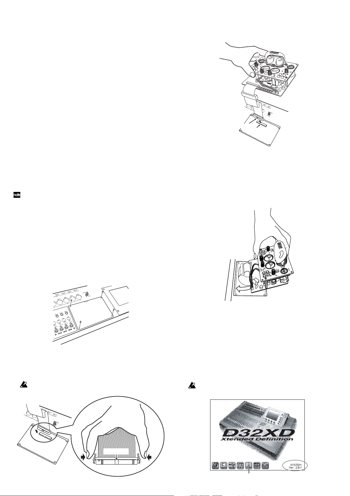
5. Insert the TPB-2's flat cable into the connector.
Make sure that the connector is oriented correctly, and press it firmly
in until the connector lock engages.
Protrusions
Tab
Installing the TPB-2
Before you install the TPB-2, make sure that your D32XD/D16XD’s
operating system is version of 2.0 or higher. The system version is
displayed in the LCD screen when you turn on the power (see the
illustration in step 8).
For details on how to update the system, refer to page 95 “Updating the
system” in the D32XD/D16XD owner’s manual.
1. You will need a Phillips (+) screwdriver.
2. Turn off the power of the D32XD/D16XD, and disconnect all
cables.
The interior of the D32XD/D16XD reaches high temperatures during
operation. Before you perform this operation, turn off the power and
wait at least 30 minutes for the interior to cool down.
3. Use the screwdriver to remove the four screws that fasten
the AIB-8 cover (or AIB-8).
Be careful not to lose these screws; you will need them to install the
TPB-2.
AIB-8 cover
or AIB-8
4. Remove the AIB-8 cover (or AIB-8).
If the AIB-8 is installed, release the flat cable of the AIB-8 from the
connector lock by squeezing in on the tabs on the side of the cable
(see the illustration below), and remove it.
The flat cable and the AIB-8 will be damaged if you forcibly pull the cable
without releasing the lock.
6. Install the AIB-8 in the D32XD/D16XD.
First, insert the front edge (the edge where the cable is located) into
the opening that had been covered by the AIB-8 cover (or AIB-8), so
that the flat cable is folded inside the D32XD/D16XD. Next, lower
the back edge into place.
7. Fasten the AIB-8 in place, using the four screws that you
removed and remembered not to lose in step 3.
8. When you are finished, turn on the power and verify that
the TPB-2 is installed correctly.
If it is installed correctly, the TPB-2 icon will appear in the LCD
screen when you turn on the power.
If this icon is not displayed, it may be that the TPB-2 was not
installed correctly. Immediately turn off the power, and verify that it
was installed correctly.
Even if the TPB-2 is installed correctly, the TPB-2 icon will not appear if
the D32XD/D16XD system version is not 2.0 or higher.
Protrusions
Locking connector
TPB-2 icon
System version
Page 3

1. Parts and their function
1
2
3
4
5
7
6
1. INPUT 9, INPUT 10 jacks
These are balanced inputs that combine XLR jacks and 1/4” TRS
phone jacks.
Unbalanced phone plugs may also be connected to the 1/4” jacks.
If you are using a condenser mic requiring phantom power, connect it
to the XLR jack.
1/4" TRS phone jack
If you are using a guitar or the line output from an instrument,
connect it to the TRS phone jack.
Balanced phone plug Unbalanced phone plug
2. Phantom power switch/LED
This switch supplies +48V phantom power to condenser mics. The
LED will light if +48V power is being supplied. Power is supplied
only to the XLR jack. Turn this off (LED dark) if you’re using a
dynamic mic.
If a condenser mic is connected or disconnected with the phantom power
switch on, damage to your equipment may occur. For this reason, always
turn the phantom power switch off before connecting or disconnecting a
condenser mic.
3. Gain trim knob
This knob adjusts the input gain. If the PAD switch is on (pushed in),
the range is +14 – –34 dBu. If the PAD switch is off, the range is –12 –
–60 dBu.
4. Hi-Z switch
This switch changes the impedance level of the TRS phone jack to
high impedance. It is on when the switch is pushed in. Turn this
switch on when connecting a high output impedance device such as
guitar or bass.
5. PAD switch
This switch lowers the level of the input signal by 26 dB. The pad is
on when the switch is pushed in. When a line level input source is
connected, turning the pad on will allow the gain trim knob to have a
wider useful range of adjustment.
6. Compressor mode switch
This switch changes the compressor’s response speed. Use the Fast
setting for short sounds such as drums or percussion, and the Slow
setting (press the switch in) for more sustained sounds, such as
vocals.
7. Low cut switch
This switch activates a 70 Hz –6 dB/oct low cut filter.
Use this to reduce unwanted low-frequency content. The filter is on
when the switch is pressed in.
891110
XLR jack
GND
COLD
HOT
2: HOT
1: GND
3: COLD
GND HOT
8. Level meter
The meter shows the audio level. If the needle moves into the red
area above 0 dB, this indicates that digital clipping is occurring.
Set the gain trim knob and the compressor sensitivity knob to prevent
the needle from exceeding 0 dB.
9. Gain reduction LED
This LED will light when gain reduction is being applied by the
compressor.
10. Compressor sensitivity knob
This specifies the audio level where the compressor begins to kick in.
Turning the knob toward the right will increase the sensitivity, so that
compression will be applied even at low levels.
If you don’t want to apply compression, turn this knob all the way to
the left.
11. Link switch
Press this switch in to link the two channels together for use with
stereo sources. When linked, compression will be applied equally to
both channels whenever either channel exceeds the compressor’s
sensitivity threshold, preserving the stereo imaging.
2. Operation
2-1. Assigning the input
The inputs of the TPB-2 will show up as Input 9 and Input 10 on your
D32XD/D16XD. The audio sources connected to the TPB-2’s inputs can
be assigned to any of the mixer channels. (See D32XD/D16XD owner’s
manual, p.42 “1. Inputting audio to the mixer”)
Preamp input INPUT 9 is shown as the icon, and INPUT10 is shown
as the icon.
•Access the MIXER, INPUT/OUTPUT/CH ASSIGN, “Ch Assign”
tab page.
•Select “SOURCE” for the channel you want to assign, and use the
buttons to select . You can also use the value dial or the
+/– keys to make this selection. In the same way, select for
another channel.
2-2. Adjusting the input level
When you’ve finished making your connections, watch the TPB-2’s level
meter while you use the gain trim knob to adjust the level. Set the trim
knob so that the level meter needle does not exceed 0 dB when the
loudest sound is input.
If the level meter goes beyond 0 dB even when the gain trim knob is
turned all the way toward the left, press the PAD switch and then use
the gain trim knob to adjust the level.
Normally if the needle goes beyond 0 dB, digital clipping has occurred, causing distortion. You should set the level so that it does not exceed 0 dB.
2-3. Using the compressor
urn the compressor sensitivity knob all the way to the left so that the
compressor is not being applied.
Use the gain trim knob to raise the level so that the meter slightly
exceeds 0 dB during the loudest input passages.
Slowly turn the compressor sensitivity knob toward the right. The gain
reduction LED will begin to light, indicating that the compressor is
being applied.
While watching the level meter, continue turning the compressor
sensitivity knob until the level does not exceed 0 dB during the loudest
input passages.
If you want to apply a lot of compression to intentionally “squash” a
vocal, use the gain trim knob to raise the input level further, and turn the
compressor sensitivity knob toward the right to increase the compression.
By using the gain trim knob to raise the preamp level appropriately , you can
saturate the vacuum tube, generating analog overtones to enrich the sound
in conjunction with the compressor.
Page 4

2-4. Using the link switch
Turn on the link switch if you want to use stereo compression.
When you’re recording a stereo source, and the level of one channel rises
to the point where compression is being applied to only that one
channel, then the relative volume of the other channel will increase,
producing the impression that the stereo image has shifted to one side.
In such cases, turning on the link switch will automatically apply
compression to both channels at the same time, whenever either channel
reaches the compressor’s threshold level.
So that the compressors for both channels will function in the same way,
select the same compressor mode setting for both channels (either Fast
or Slow). You should also set the compressor sensitivity knob to about
the same setting for both channels.
3. A note about the vacuum tubes
This device contains vacuum tubes. We recommend that you allow the
tubes to warm up for about ten minutes after you turn on the power,
before you begin running any audio signals through the TPB-2.
If you begin using this device immediately after turning on the power,
this may cause malfunctions and/or shorten the life of the vacuum
tubes.
In order to maximize reliability, avoid placing this device above or
below heat-producing equipment such as a power amp.
Do not attempt to remove, replace or change the tubes in the TPB-2. The
tubes are not a user serviceable part.
Vacuum tubes generate heat. Do not allow your skin to contact the vacuum
tube cover for an extended period of time. Doing so can cause low-temperature burns.
4. Specifications
Input connectors: XLR-3-31 type (+48 V phantom power, switchable),
1/4” TRS phone jack (balanced / unbalanced is Hi-Z)
Input impedance: 4 k (XLR-3-31), 10 k (TRS phone Jacks),
1 M (TRS phone Jacks is Hi-Z)
Nominal level: –60 dBu to –12 dBu @ TRIM=max. — min PAD OFF
–34 dBu to +14 dBu @ TRIM=max. — min PAD ON
Maximum level: –48 dBu to 0 dBu @ TRIM=max. — min PAD OFF
–22 dBu to +26 dBu @ TRIM=max. — min PAD ON
Hi-Z
– 48 dBu to 0 dBu @ TRIM=max. — min PAD OFF
– 22 dBu to +12 dBu @ TRIM=max. — min PAD ON
Source impedance: ..................................................................................... 600
Vacuum tubes used:................................................................................. 12AX7
Compression method: Vacuum tube compression using a photocoupler
Principal specifications
Frequency response:
10 Hz - 20 kHz ±1 dB @ fs 44.1 kHz, +4 dBu, 10 k load
10 Hz - 22 kHz ±1 dB @ fs 48 kHz, +4 dBu, 10 k load
10 Hz - 44 kHz ±1 dB @ fs 96 kHz, +4 dBu, 10 k load
S/N: ............................................................................................. 93 dB (typical)
TPB-2 [ Tube Preamp Option ] for D32XD/D16XD
10
9
GAIN
TRIM
GAIN
TRIM
GR
GR
HI-Z
HI-Z
PHASE
PHASE
PAD
PAD
HA
HA
LOWCUT
LOWCUT
INPUT
PHANTOM
+48V
INPUT
PHANTOM
+48V
LEVEL METER
TUBE
COMP
SENS
LINK
LEVEL METER
TUBE
COMP
SENS
AD
AD
 Loading...