

Korg SDD-200 Owner's Manual
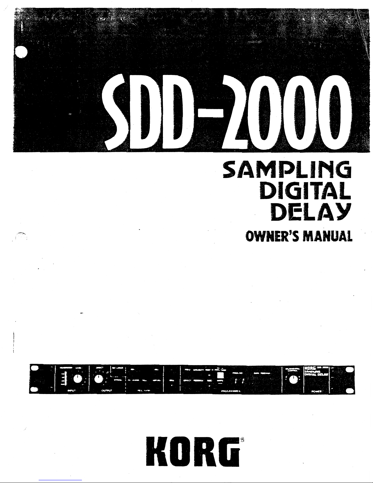
SAMPLING
DIGITAL
DELAY
OWNER'S
MANUAL
KORG
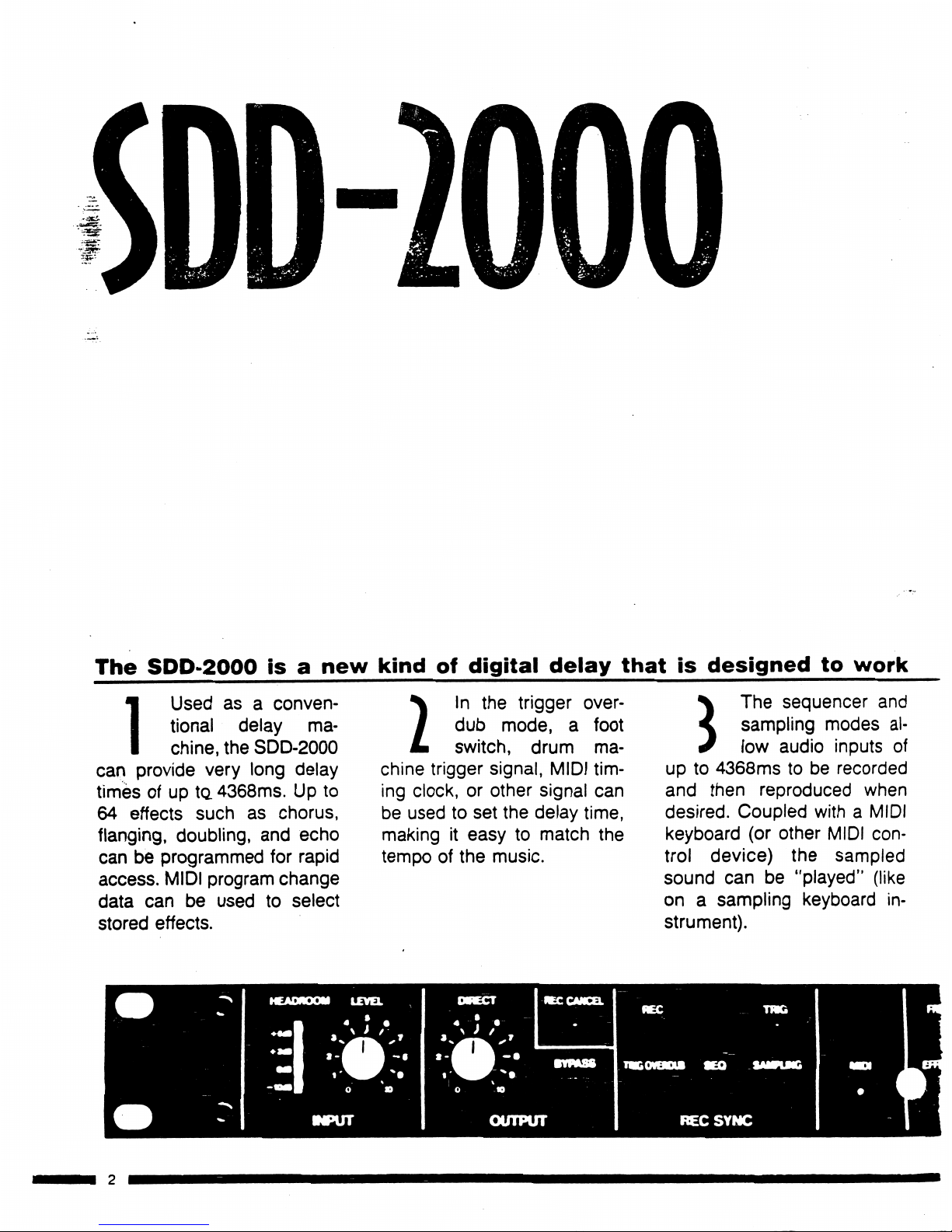
The
SDD-2000
isanew
kind
of
digital
delay
that
is
designed
to
work
IUsed
asaconven
tional
delay
ma
chine,
the
SDD-2000
can
provide
very
long
delay
timesofup
to.
4368ms.Upto
64
effects
suchaschorus,
flanging,
doubling,
and
echo
canbeprogrammed
for
rapid
access.
MIDI
program
change
data
canbeusedtoselect
stored
effects.
N
In
the
trigger
over-
I
dub
mode,afoot
L
switch,
drum
ma
chine
trigger
signal,
MIDI
tim
ing
clock,orother
signal
can
be
usedtoset
the
delay
time,
makingiteasytomatch
the
tempoofthe
music.
The
sequencer
and
sampling
modes
al-
low
audio
inputs
of
upto4368mstobe
recorded
and
then
reproduced
when
desired.
Coupled
withaMIDI
keyboard
(or
other
MIDI
con
trol
device)
the
sampled
sound
canbe"played"
(like
onasampling
keyboard
in
strument).
n
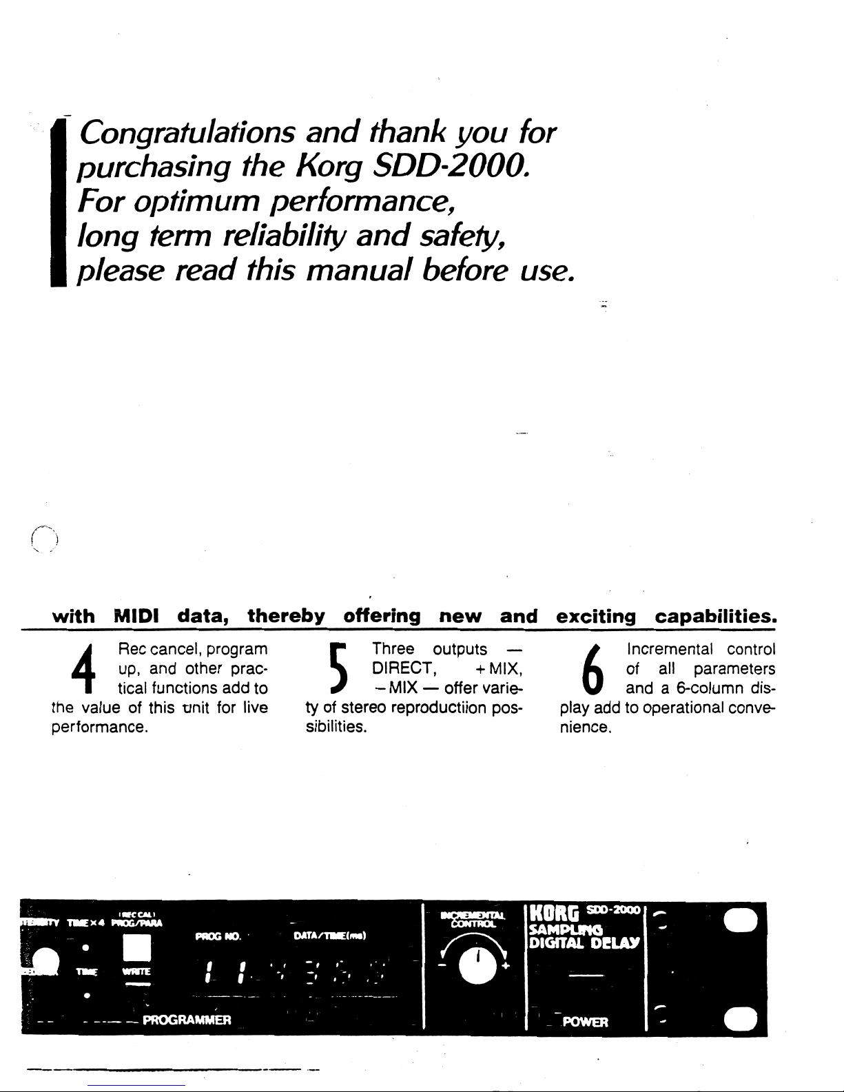
Congratulations
and
thank
you
for
purchasing
the
Korg
SDD-2000.
For
optimum
performance,
long term
reliability
and
safety,
please
read
this
manual
before
use.
with
MIDI
data,
thereby
offering
new
and
exciting
capabilities.
4
Rec
cancel,
program
up,
and
other
prac
tical
functions
add
to
the
valueofthis
tjnit
for
live
performance.
Three
outputs
—
DIRECT,
+MIX,
-
MIX—offer
varie
tyofstereo
reproductiion
pos
sibilities.
6
Incremental
control
of
all
parameters
anda6-column
dis
play
addtooperational
conve
nience.
(■KCAll
MTV
TMEX4
PWOG/HUU
:
—
■■■
PROG
NO.
*
eHV
twe
wwte
'
'
•^
•
;•
-..
[_-
'
PROGRAMMER
—■
OATA/TME(mt)
•ssss*
DIGITAL
DELAY
POWER
To
avoid
malfunction
do
not
use
this
unit
in
the
follow
ing
locations
for
long
periods
of
time:
•
In
direct
sunlight
^^^^«S
•
Exposed
to
extrernes
of
temperature
or
humidity;
•
In
sandy
or
dusty
places.
POWER
SUPPLY
■•
Useonly
with
rated
AC
voltage.
If
you
will
be
using
this
unit
ina
country
having
a
different
voltage,
be
sure
to
obtain
the
proper
transformer
to
convert
to
•
To
helpiprevent
rioiseand
diBgraded
sound
quality,
avoid
usingthe
sam&outletas
other
equipment
or
branching
off
extension
cords
shared
by
other
equipment
HANDLE
GENTLY
Knobs
and
switches
are
designed
to
provide
positive
operation withalight
touch.
Excessive
force
may
cause
damage:
MAINTENANCE
Wipe
the
exterior
withasoft,
dry
cloth.
Never
use
paint
thinner,
benzene
or
other
solvents.
■
■.■•■■•'■I•■■"■
.■■'*"
PREVENTING
ELECTRICAL
INTERFERENCE
Erratic
performance
may
be
caused
by
electrical
in-
terference
from
nearby
appliances
(radio,
TA/,
etc:)rOT
especially
those
with
motors.
Avoid
operating
this
unit
near
possible
sources
of
interference.
KEEP
THIS
MANUAL
Store
this
manual
inasafe
place
of
future
reference.
MM
Id
ipireyi^
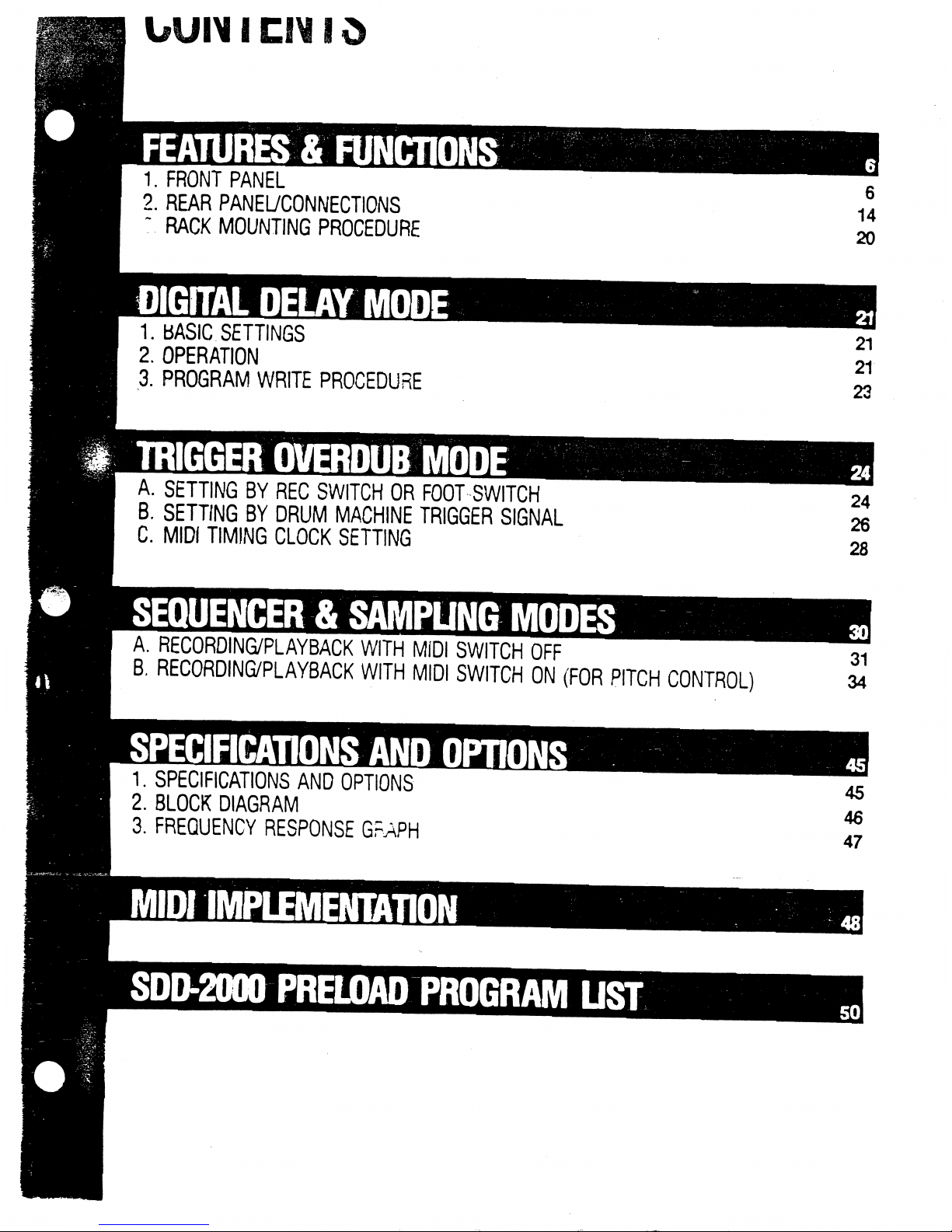
FEATURES
&
FUNCTIONS
1.
FRONT
PANEL
2.
REAR
PANEL/CONNECTIONS
:.
RACK
MOUNTING
PROCEDURE
DIGITAL
DELAY
MODE
1.
BASIC
SETTINGS
2.
OPERATION
3.
PROGRAM
WRITE
PROCEDURE
6
14
20
21
21
23
A.
SETTING
BY
REC
SWITCH
OR
FOOT
SWITCH
B.
SETTING
BY
DRUM
MACHINE
TRIGGER
SIGNAL
C.
MIDI
TIMING
CLOCK
SETTING
24
26
28
A.
RECORDING/PLAYBACK
WITH
MIDI
SWITCH
OFF
B.
RECORDING/PLAYBACK
WITH
MIDI
SWITCH
ON
(FOR
PITCH
CONTROL)
1.
SPECIFICATIONS
AND
OPTIONS
2.
BLOCK DIAGRAM
3.
FREQUENCY
RESPONSE
GRAPH
45
46
47
SDD-2000
PRELOAD
PROGRAM
UST

1
FRONT
PANEL
INPUT
SECTION
OUTPUT
SECTION
2
Input
LEVEL
Control—
1
HEADROOM
Indicator-
o
HEAOFDOM
♦
6dB
008
-KWB
2+
\U
0
10
INPUT
OWECT
4
j
i.
*9
-3
DIRECT
Volume
Control
-4
BYPASS
Switch
-5
REC
CANCEL
LED
/
|RPCCLNC£L|
C)
REC
TWG
10
BYPASS
ME
OUTPUT
•RKOVSOue
SEO
SAMPUNG
recSync
REC
SYNC
SECTION
6
REC
Switch
7
TRIG
OVERDUB
Switch-
8
SEQ
Switch
9
SAMPLING
Switch-
10
TRIG
LED
Mia
Ef
f
PROGRAMMER
SECTION
-ism
-
if
PROG
NO
)ATA/flME(ms)
\
PROGRAMMER
-12
FREQ
Switch
-14
EFFECT
Switch
-13
INTENSITY
Switch
-15
FEEDBACK
Switch
-16TIMEX4Switch
-17
TIME
Switch
-18
PROG/PARA
(REC
CAL)
-19
WRITE
Switch
-20
DISPLAY
-21
INCREMENTAL
CONTROL
INCREA
ENTAL
CONTROL
KORC*»t00°
SAMPLIMG
DIGITAL
DCLAV
POWER
Switch
-22POWER
Switch
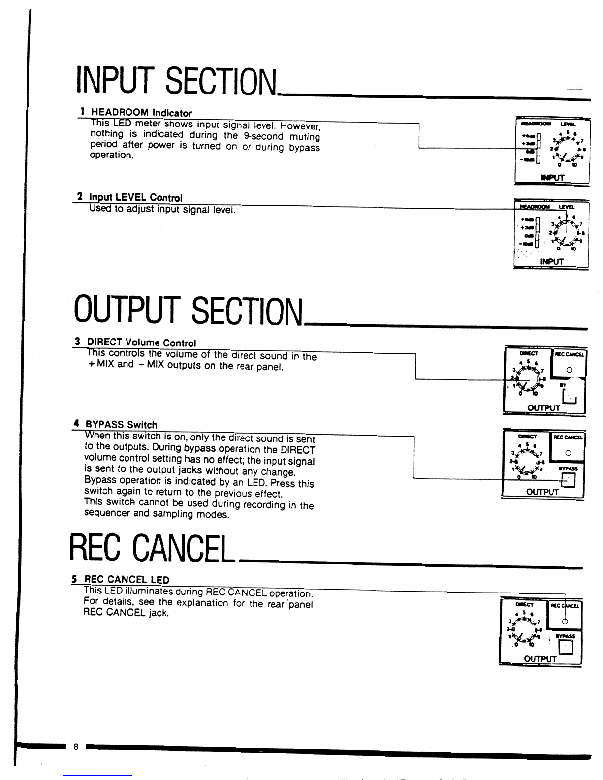
INPUT
SECTION.
I
HEADROOM
Indicator
This
LED
meter
s
ihows
input
signal
level.
However,
nothingisindicated
during
the
9-second
muting
period
after
poweristurnedonor
during
bypass
operation.
2
Input
LEVEL
Control
Usedtoadjust
input
signal
level.
OUTPUT
SECTION.
3
DIRECT
Volume
Control
is
controls
the
volumeofthe
direct
soundinthe
+
MIX
and-MIX
outputsonthe
rear
panel.
4
BYPASS
Switch
J
this
switchison,
only
the
direct
soundissent
to
the
outputs.
During
bypass
operation
the
DIRECT
volume
control
setting
has
no
effect;
the
input
signal
is
sent
to
the
output
jacks
without
any
change.
Bypass
operation
is
indicated
by
an
LED.
Press
this
switch
againtoreturntothe
previous
effect.
This
switch
cannot
be
used
during
recording
in
the
sequencer
and
sampling
modes.
REC
CANCEL
5
REC
CANCEL
LED
This
LED
illuminates
during
REC
CANCEL
operation.
For
details,
see
the
explanation
for
the
rear
panel
REC
CANCEL
jack.
O*ECT
|REC
CANCEL
|
« ?
•
O
BYPASS
OUTPUT
■a
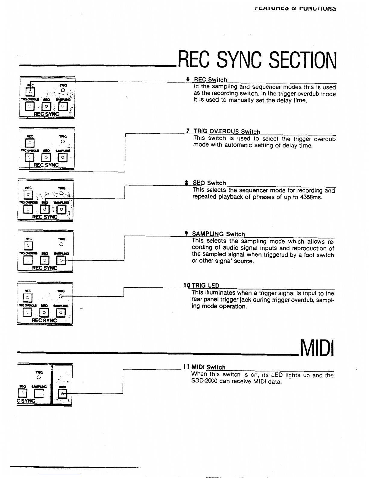
REC
SYNC
SECTION
mo
saotlmq
SEE
RECSYNC
6
REC
Switch
In
the
sampling
and
sequencer
modes
thisisused
as
the
recording
switch.Inthe
trigger
overdub
mode
itisusedtomanually
set
the
delay
time.
7
TRIG
OVERDUB
Switch
This
switchisusedtoselect
the
trigger
overdub
mode
with
automatic
setting of
delay
time.
t
SEQ
Switch
This
selects
the
sequencer
mode
for
recording
and
repeated
playbackofphrasesofupto4368ms.
SAMPLING
Switch
This
selects
the
sampling
mode
which
allows
re
cordingofaudio
signal
inputs
and
reproduction
of
the
sampled
signal
when
triggered
byafoot
switch
or
other
signal
source.
10
TRIG
LED
This
illuminates
whenatrigger
signalisinputtothe
rear
panel
trigger
jack
during
trigger
overdub,
sampl
ing
mode
operation.
csync
MIDI
11
MIDI
Switch
When
this
switchison,
its
LED
lightsupand
the
SDD-2000
can
receive
MIDI
data.
PROGRAMMER
SECTION.
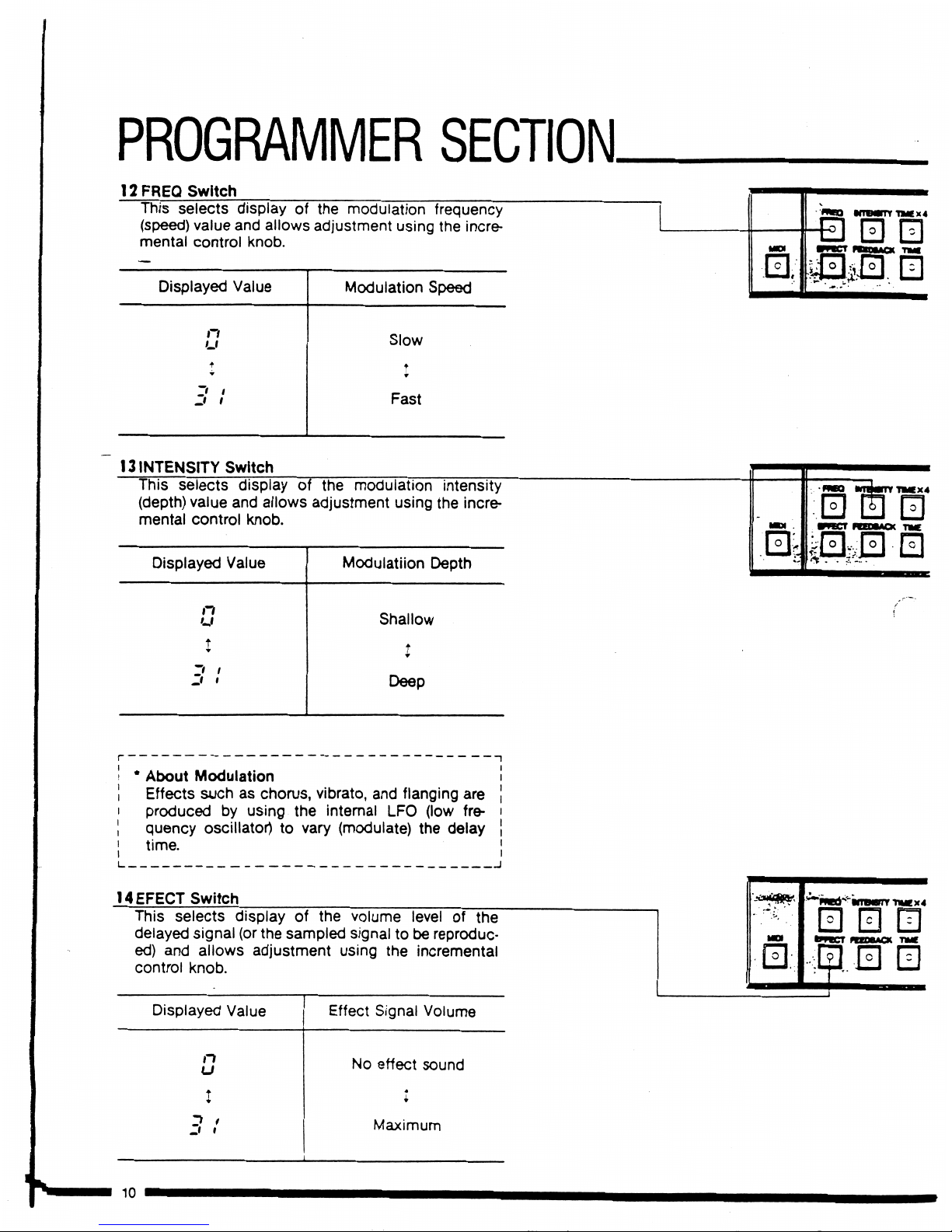
12
FREQ
Switch
This
selects
displayofthe
modulation
frequency
(speed)
value
and
allows
adjustment
using
the
incre
mental
control
knob.
Displayed
Value
n
u
Z*
i
Jf
t
Modulation
Speed
Slow
♦
Fast
13
INTENSITY
Switch
This
selects
displayofthe
modulation
intensity
(depth)
value
and
allows
adjustment
using
the
incre
mental
control
knob.
Displayed
Value
n
u
I
Z*
i
ji
i
Modulation
Depth
Shallow
t
Deep
B
TKX4
IOI
*
About
Modulation
Effects
suchaschorus,
vibrato,
and
flanging
are
producedbyusing
the
internal
LFO
(low
fre
quency
oscillator)
to
vary
(modulate)
the
delay
time.
14EFECT
Switch
This
selects
displayofthe
volume
levelofthe
delayed
signal
(or
the
sampled
signaltobe
reproduc
ed)
and
allows
adjustment
using
the
incremental
control
knob.
Displayed
Value
n
u
Effect
Signal
Volume
No
effect
sound
Maximum
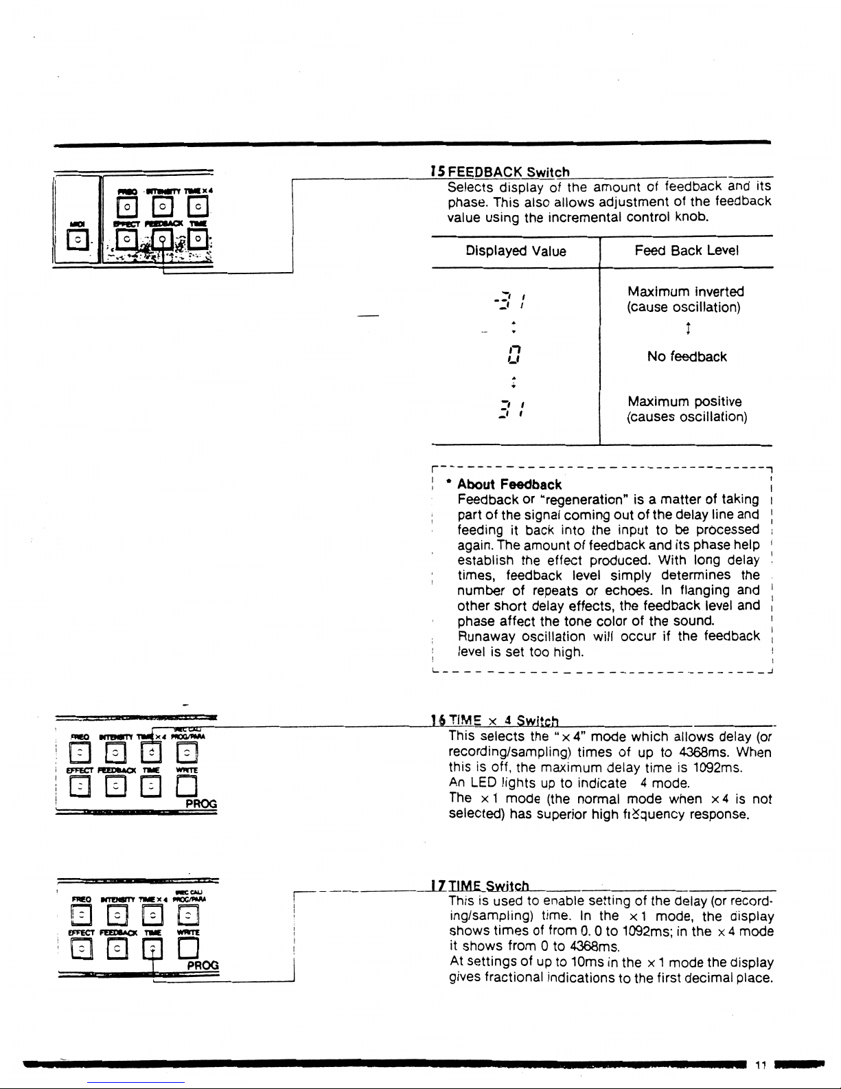
15
FEEDBACK
Switch
Selects
displayofthe
amountoffeedback
and
its
phase.
This
also
allows
adjustmentofthe
feedback
value
using
the
incremental
control
knob.
Displayed
Value
.I'
i
A
—
-9
n
u
I
Z*
t
Feed
Back
Level
Maximum
inverted
(cause
oscillation)
I
No
feedback
Maximum
positive
(causes
oscillation)
About
Feedback
Feedbackor"regeneration"
isamatteroftaking
partofthe
signal
coming
outofthe
delay
line
and
feedingitback
into
the
inputtobe
processed
again.
The
amountoffeedback
and
its
phase
help
establish the
effect
produced.
With
long
delay
times,
feedback
level
simply
determines
the
numberofrepeatsorechoes.Inflanging
and
other
short
delay
effects,
the
feedback
level
and
phase
affect
the
tone
colorofthe
sound.
Runaway
oscillation
will
occurifthe
feedback
levelisset
too
high.
16
TIMEx4
Switch
This
selects
the
"x4"
mode
which
allows
delay
(or
recording/sampling)
timesofupto4368ms.
When
thisisoff,
the
maximum
delay
timeis1092ms.
An
LED
lightsupto
indicate4mode.
Thex1mode
(the
normal
mode
whenx4is
not
selected)
has
superior
high
frequency
response.
17TIME
Switch
Thisisusedtoenable
settingofthe
delay
(or
record
ing/sampling)
time.Inthex1mode,
the
display
shows
timesoffrom0.0to1092ms;inthex4
mode
it
shows
from0to
4368ms.
At
settingsofupto10msinthex1
mode
the
display
gives
fractional
indications
to
the
first
decimal
place.
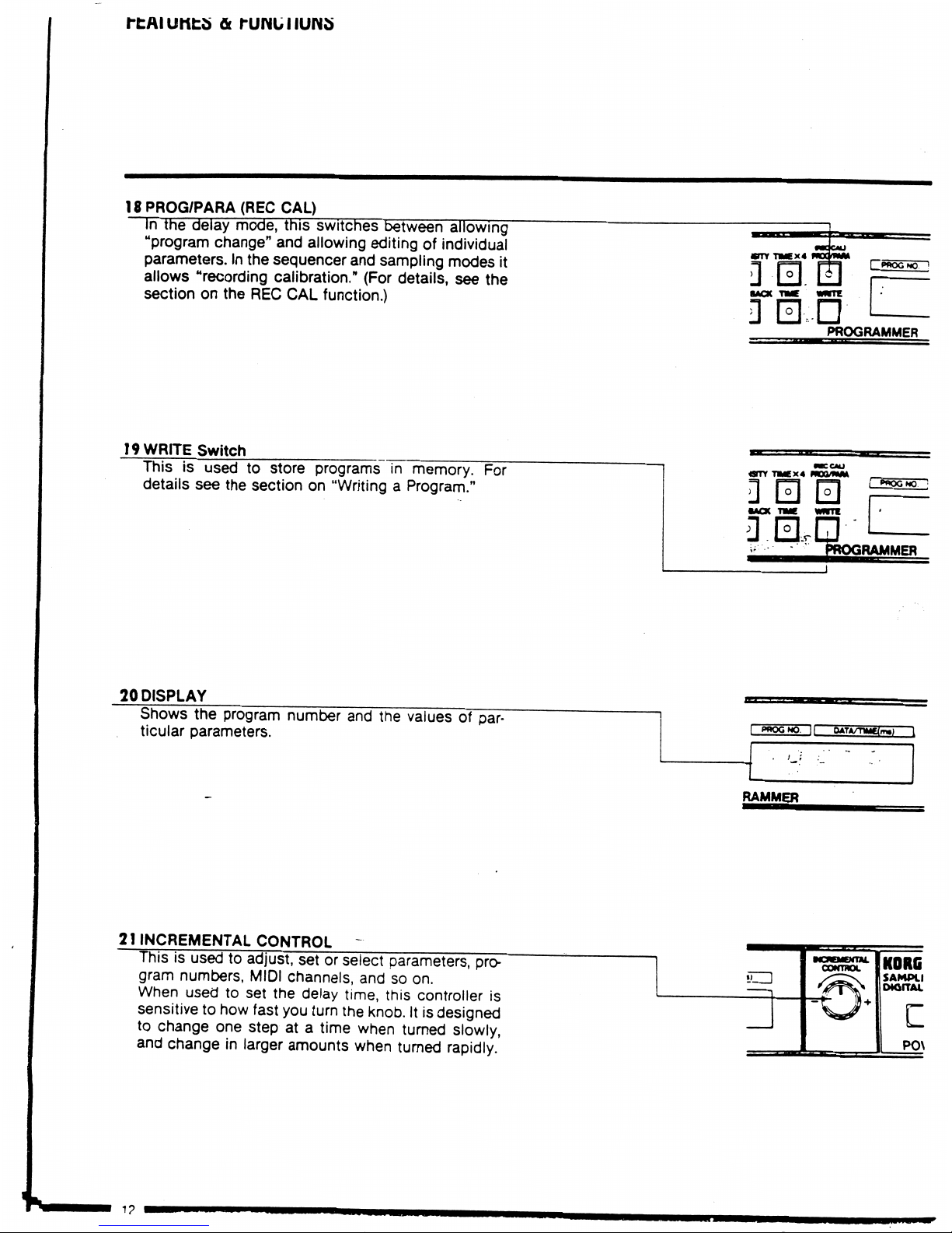
18
PROG/PARA
(RECCAL)
In
the
delay
mode,
this
switches
between
allowing
"program
change"
and
allowing
editingofindividual
parameters.
In
the
sequencer
and
sampling
modes
it
allows
"recording
calibration."
(For
details,
see
the
sectiononthe
REC
CAL
function.)
19
WRITE
Switch
Thisisusedtostore
programsinmemory.
For
details
see
the
sectionon"WritingaProgram."
OTY-nMEx4
mum*
0
0 0
I
PWQGNQ.
3
;
oi
Is*
MER
20
DISPLAY
Shows
the
program
number
and
the
valuesofpar-
ticular
parameters.
RAMMER
21
INCREMENTAL
CONTROL
-
Thisisusedtoadjust,
setorselect
parameters,
pro-
gram
numbers,
MIDI
channels,
andsoon.
When
usedtoset
the
delay
time,
this
controller
is
sensitive
to
how
fast
you
turn
the
knob.Itis
designed
to
change
one
stepata
time
when
turned
slowly,
and
changeinlarger
amounts
when
turned
rapidly.
POWER
{MENTAL
•rraoc
KOMi
■M000
SAMPLING
MOfTAL
DCLAy
POWER
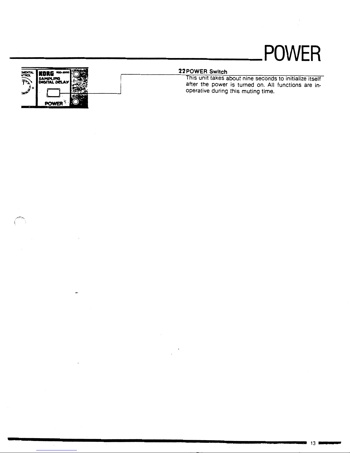
22
POWER
Switch
This
unit
takes
about
nine
secondstoinitialize
itself
after
the
poweristurned
on.
All
functions
are
in
operative
during
this
muting
time.
I
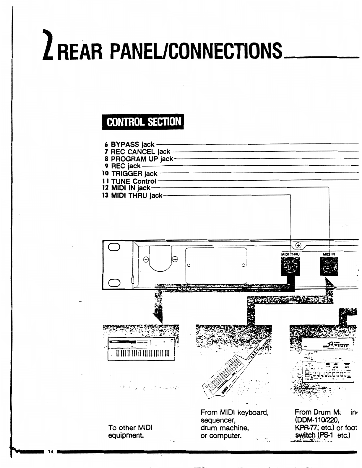
REAR
PANEL/CONNECTIONS
CONTROL
SECTION
6
BYPASS
jack
7
REC
CANCEL
jack-
8
PROGRAMUPjack-
9
REC
jack
10
TRIGGER
jack—
11
TUNE
Control—
12
MIDIINjack
13
MIDI
THRU
jack-
wmmmm
To
other
MIDI
equipment
From
MIDI
keyboard,
sequencer,
drum
machine,
or
computer.
From
Drum
Mi
in<
(DDM-1107220,
KPR-77,
etc.)
or
foot
switch
(PS-1
etc.)
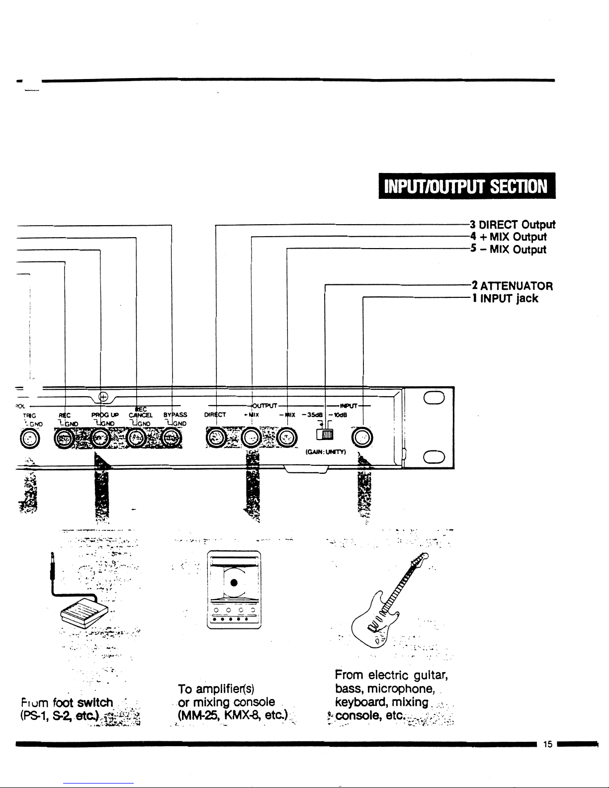
INPUT/OUTPUT
SECTION
<£>
TRIG
R«C
PRXjUP
CANCEL
BYf>ASS
"-GNO
1-bNO
"UGNO
UGNO
-3
DIRECT
Output
-4+MIX
Output
-5-MIX
Output
-2
ATTENUATOR
1
INPUT
jack
hum
foot
switch
To
amplifier(s)
or
mixing
console
(MM-25,
KMX-8,
etc)
From
electric
guitar,
bass,
microphone,
keyboard,
mixing.
.-
,
etc..-..:,-:
15
 Loading...