

Page 1

73key
88key
Owner’s manual
Manuel d’utilisation
Bedienungsanleitung
Page 2

Page 3
Precautions
Location
Using the unit in the following locations can result in a
malfunction.
• In direct sunlight
• Locations of extreme temperature or humidity
• Excessively dusty or dirty locations
• Locations of excessive vibration
• Close to magnetic fields
Interference with other electrical devices
Radios and televisions placed nearby may experience reception interference. Operate this unit at a suitable distance
from radios and televisions.
Handling
To avoid breakage, do not apply excessive force to the
switches or controls.
Care
If the exterior becomes dirty, wipe it with a clean, dry cloth.
Do not use liquid cleaners such as benzene or thinner, or
cleaning compounds or flammable polishes.
Keep this manual
After reading this manual, please keep it for later reference.
Keeping foreign matter out of your equipment
Never set any container with liquid in it near this equipment. If liquid gets into the equipment, it could cause a
breakdown, fire, or electrical shock. Be careful not to let
metal objects get into the equipment.
Notice regarding disposal (for EU)
If this “crossed-out wheeled bin” symbol is shown
on the product or in the operating manual, you
must dispose of the product in an appropriate
way. Do not dispose of this product along with
your household trash. By disposing of this product
correctly, you can avoid environmental harm or
health risk. The correct method of disposal will depend on your locality, so please contact the appropriate local authorities for details.
THE FCC REGULATION WARNING (for USA)
This equipment has been tested and found to comply
with the limits for a Class B digital device, pursuant to
Part 15 of the FCC Rules. These limits are designed to
provide reasonable protection against harmful interference in a residential installation. This equipment generates, uses, and can radiate radio frequency energy and,
if not installed and used in accordance with the instructions, may cause harmful interference to radio communications. However, there is no guarantee that interference will not occur in a particular installation. If this
equipment does cause harmful interference to radio or
television reception, which can be determined by turning the equipment off and on, the user is encouraged to
try to correct the interference by one or more of the following measures:
• Reorient or relocate the receiving antenna.
• Increase the separation between the equipment and
receiver.
• Connect the equipment into an outlet on a circuit different from that to which the receiver is connected.
• Consult the dealer or an experienced radio/TV technician for help.
Unauthorized changes or modification to this system
can void the user’s authority to operate this equipment.
* Company names, product names, and names of formats
etc. are the trademarks or registered trademarks of their
respective owners.
3
Page 4
KKS (KORG Komponent System)
This instrument is part of the KORG Komponent System.
This versatile system keeps all of the sound generating circuitry, all of the external connectors and even the power
supply together inside of the sound module (subsequently
referred to as the modsë). In this way, the instrument may
be played with the module section tilted up or lying flat. In
addition, the module section may be completely removed
and operated as an independent tone module, or used with
other KKS products for further convenience.
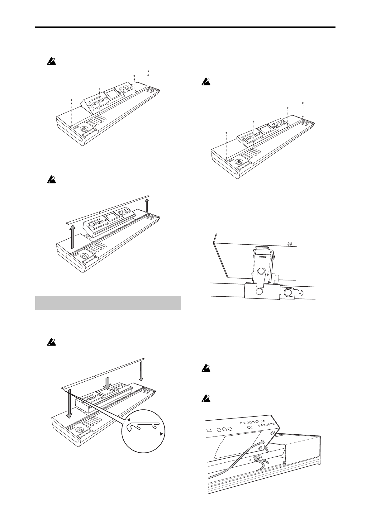
Parts and their functions
Keyboard Assembly
4
3
2
1
5
9
6.
TO MODULE connector/TO MODULE(2nd) connector
One end of the connecting cable (8) will plug into this jack,
and the other end will plug into the module’s TO KYBD
port. When connected, you’ll be able to use the keyboard
assembly’s keyboard, joystick, ribbon controller and
switches to control the module. If you’re using only one
module, connect it to the TO MODULE connector.
Certain modules may not support all of the controllers found on the keyboard assembly.
7. Connecting cable
This cable connects the keyboard assembly to the module.
8. Locking support
This part fastens the module to the keyboard assembly. The
support arm allows the rear of the module to be raised,
providing easy access to the panel controls, or lowered to
lie flat. In addition, the entire locking support can be moved
to any location along the rear rail, allowing the module to
be freely positioned.
9. Cover panels
When using a single module, these covers can be attached
to the keyboard assembly to provide a more finished look.
Locking support
6
7
8
9
TO MODULE(2nd) connector
TO MODULE connector
Expanded view of 6.
Connector area
1. Retaining bar
This part keeps the sound module and the cover panels
attached to the keyboard assembly. Four screws (M3 x 8)
with it locks.
2. Keyboard
73-key: semi-weighted
88-key: RH-3 (Real Weighted Hammer Action 3)
3. Ribbon controller
By touching or rubbing your finger on this ribbon you can
control various program and effect parameters on the connected module.
4. Joystick
By moving the joystick up/down/left/right you can control various program and effect parameters on the connected module.
5. SW1/SW2
You can use these switches to control various program or
effect parameters on the connected module, or to turn the
joystick or ribbon controller’s Lock function on/off.
6
2
1
3
Rear rail
5
4
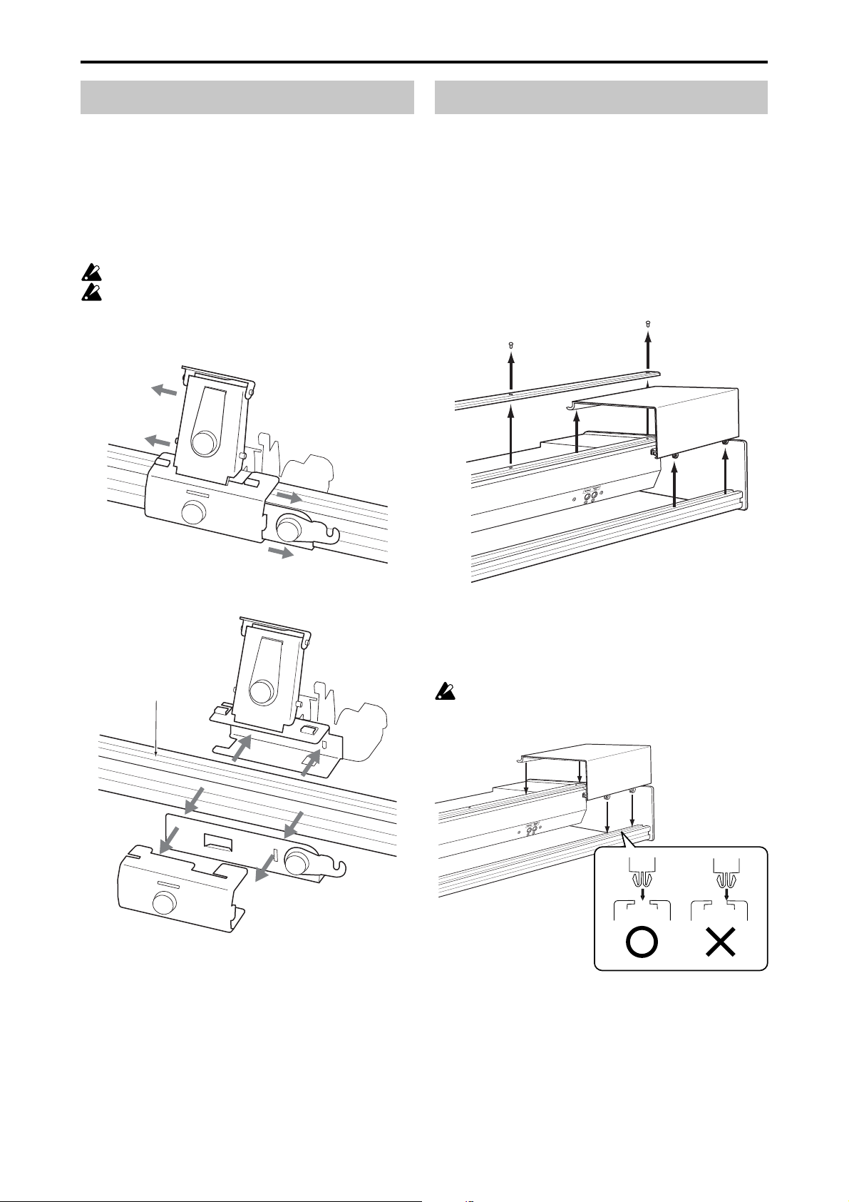
1. Bracket
This part is attached to the rear rail of the keyboard assembly. It can be moved horizontally so that you can re-position the module.
2. Support arm
This part supports the module when it’s in the raised position.
3. Lock plate
This secures the arm when you’re using the module in the
raised position.
4. Latch
This secures the module when it’s in the lowered/stored
position, lying flat on the keyboard assembly.
5. Screws A
These fasten their respective parts.
6. Screws B
These are two screws (M4 x 6) that attach the support arm
to the module.
4
Page 5
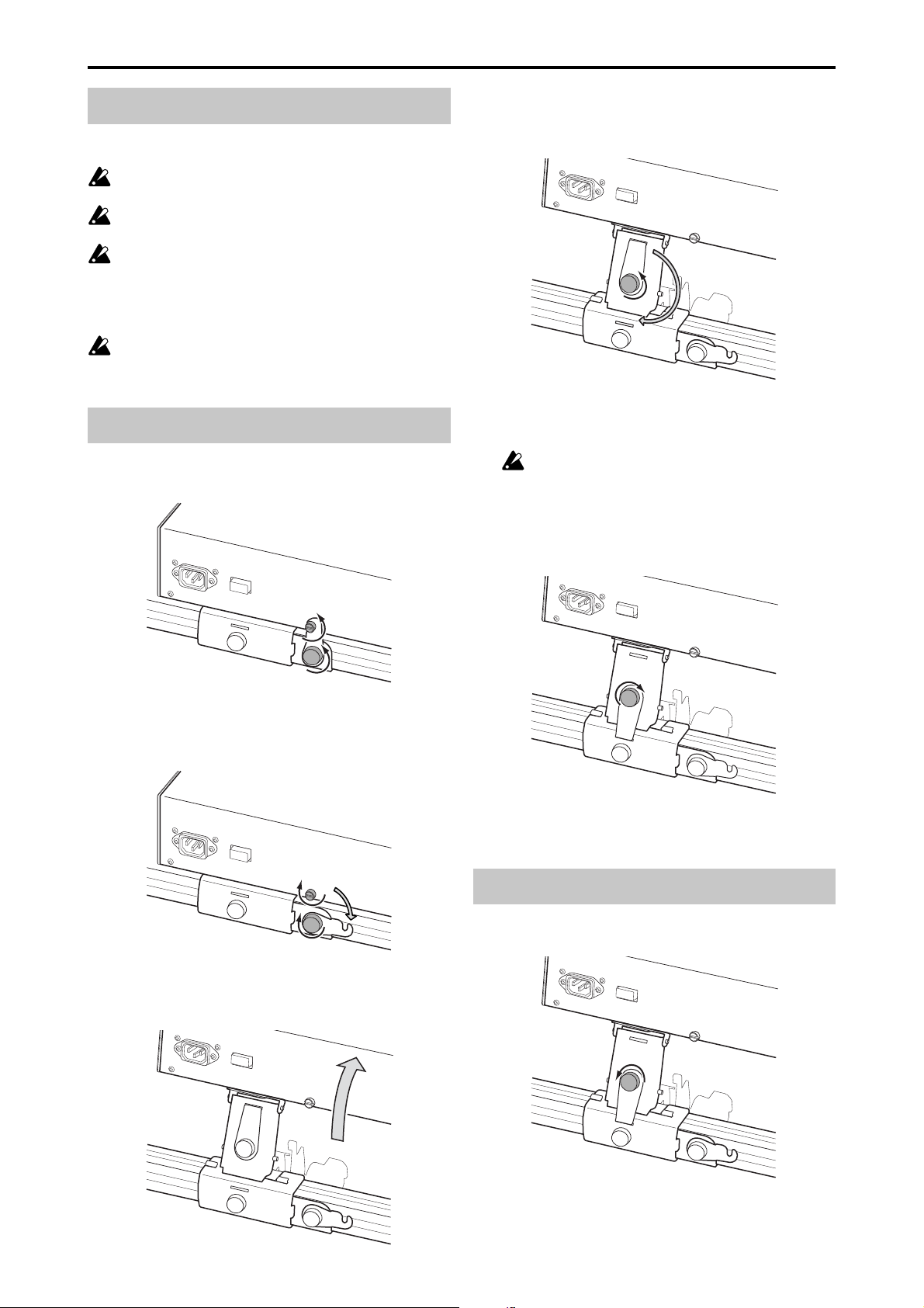
Caution when adjusting the module
4. Loosen the screw A that holds the lock plate, turn the lock
Please observe the following cautions in order to ensure
safe and correct assembly and disassembly.
Please observe the following cautions in order to ensure safe and correct use, assembly and disassembly.
Be careful not to pinch your hands or fingers while
raising or lowering the module.
Be sure that the module is powered-off when you connect or disconnect the cable between the keyboard
assembly and the module. If you connect or disconnect this cable while the power is on, the module may
stop operating correctly.
Before you proceed, be sure to read and follow the
“Safety precautions” found earlier in this manual.
plate 180 degrees as shown, and fit it into the slot in the
bracket.
Raising the module
1. Loosen both of the latch screws; the one securing the latch
to the module, and the one connected to the bracket.
2. Rotate the latch to the side as shown in the illustration,
and tighten the screw A to fasten it in place. Also tighten
the screw on the module so that it does not fall out.
5. Tighten the lock plate screw A to secure it in place.
This step is very important. If you move the keyboard assembly or apply excessive force to the
module without fastening the lock plate to the
bracket, the module may fall down resulting in
damage or injury. For safety, fit the lock plate into
the bracket and fasten it with the screw A.
3. Using the handle located on the rear panel, lift the mod-
ule until it stops; and release the handle.
Lowering the module
1. Loosen the screw A securing the lock plate.
5
Page 6
2. Rotate the lock plate 180 degrees, fit it into the slot of the
support arm, and tighten the screw to fasten it.
5. As shown in the illustration, rotate the latch to the verti-
cal position and slide it under the screw on the module.
Then tighten both screws.
3. As shown in the illustration, lightly press in on the screw
A securing the lock plate to the arm, then gently lift the
module using the handle located on the rear panel and
release it. The module will slowly pivot down.
Be careful not to pinch your hand between the
module and the keyboard assembly.
4. Loosen the screw on the module and the screw A that
secures the latch.
Module removal
1. If the module is lying flat in the storage position, raise it
as described in steps 1–5 of “Raising the module.”
2. Disconnect the cable plug (L-shaped plug) connected to
the TO KYBD connector located on the bottom of the
module.
3. As shown in the illustration, use your Phillips (+) screw-
driver to remove the two screws B that attach the support
arm to the module.
Be careful not to lose the screws you remove.
6
Page 7
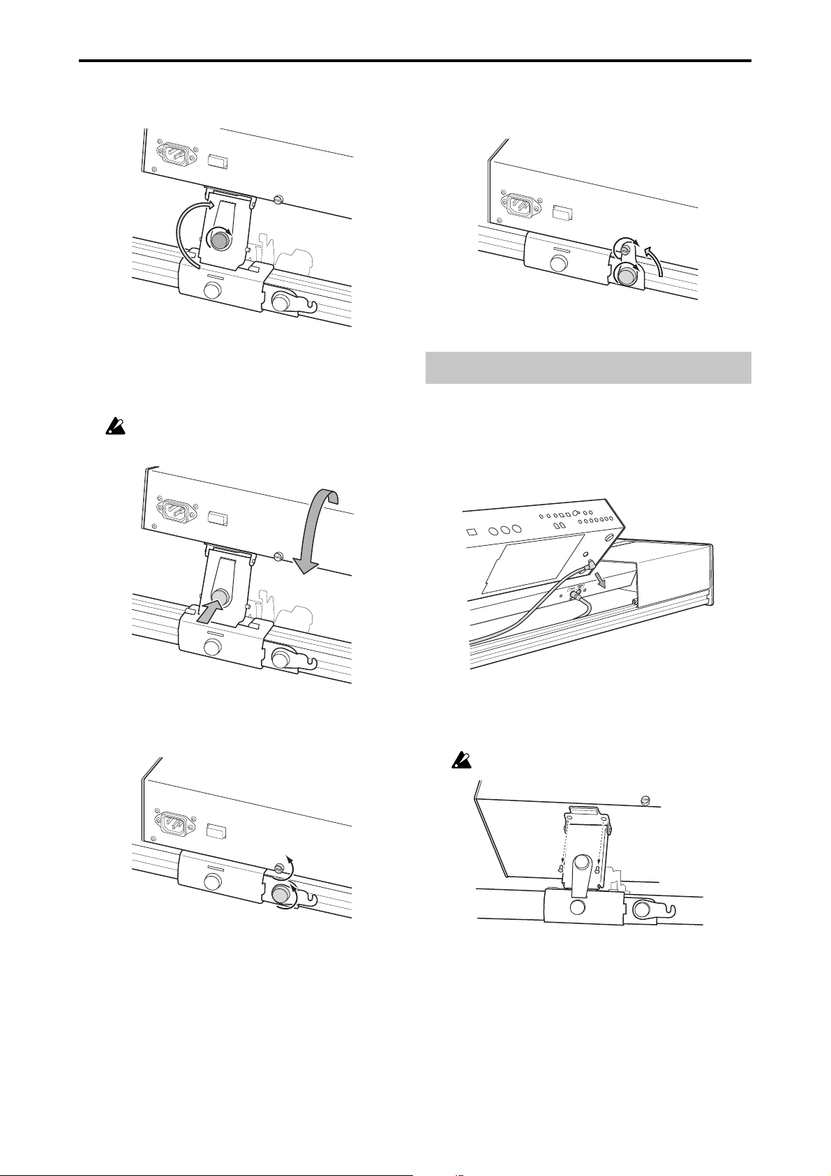
4. Use your Phillips (+) screwdriver to remove the four
screws that hold the retaining bar to the keyboard assembly.
Be careful not to lose the screws you remove.
5. Remove the retaining bar, and then lift the module using
both hands and remove it from the keyboard assembly.
Be careful not to pinch your hand between the
module and keyboard assembly.
2. Orient the retaining bar correctly as shown in the illustra-
tion, and place it on top of the module.
Align the screw holes in the retaining bar with the screw
holes in the keyboard assembly, and finger-tighten the
four screws. Finally, use your Phillips (+) screwdriver to
firmly tighten the four screws.
Don’t attempt to forcibly tighten the screws if the
screw holes are not aligned. Doing so may cause
damage to the unit.
3. Using the handle located on the rear panel, lift the mod-
ule up, align the screw holes in the module with the screw
holes in the support arm, and use your Phillips (+) screwdriver to install the two screws B that you removed when
detaching the module.
Module installation
1. Make sure that the support arm is folded down. Hold the
module in both hands and carefully place it on the keyboard assembly.
Be careful not to pinch your hand between the
module and keyboard assembly.
toward module
toward keyboard
Cross-section of
keyboard cover
4. Connect the included cable.
Connect the L-shaped plug of the cable to the TO KYBD
connector on the module, and connect the straight plug
to the TO MODULE connector on the keyboard assembly. If the TO MODULE connector is already being used
to connect another module, then use the TO MODULE
(2nd) connector.
The included cable is only for connecting the TO
KYBD connector to the TO MODULE or TO
MODULE (2nd) connector. Do not connect it to
any other connector.
If you’re using only one module, connect it to the
TO MODULE connector.
7
Page 8
Locking support assembly
Cover panels
As shown in the illustration, the support arm, bracket and
latch parts fit together around the rear rail to form the locking support assembly. The raised tabs on the support arm
slide into the slots on the top of the bracket to hold everything together. To attach the locking support assembly, fasten the bracket to the support arm by sliding it horizontally (to the left) and tightening the screw on the bracket.
To r emove the locking support assembly, loosen the screw
and slide the bracket to the right to release the two pieces.
Make sure that the bracket is oriented correctly.
When performing this step, be careful not to cut your
hand on the metal parts.
The keyboard assembly can be used with or without the these
decorative “filler” panels. The cover panels will need to be
removed when using two modules. As shown in the illustration, the front edge of the cover panels are held in place
by the retaining bar. The back edge of the cover panels fit
into the channel on the top of the keyboard assembly’s rear
rail. To remove the cover panels, remove the retaining bar as
shown in step 4 of “Module removal” and lift off the cover
panels. Replace the retaining bar as described in step 2 of
“Module installation.” To replace the cover panels, remove
the retaining bar, place the back edge of the cover panels on
the top of the rear rail, and replace the retaining bar.
Rear rail
Caution when attaching the cover panel
Align the projections of the cover panel with the slot of the
rear rail, and press the cover panel into place.
If you press the cover panel when the projections are
not aligned with the slot, you may damage the projections.
8
Page 9

If the cover panel comes open as shown below after you’ve
attached it, apply gentle pressure to the rear side and fit
the projections of the cover panel into the slot of the rear
rail.
Moving precautions
If you transport the keyboard assembly with the module in
the raised position, the lock plate must be fitted into the
slot on the bracket and secured in place by tightening the
lockplate screw. If you transport the keyboard assembly
with the module in the lowered (storage) position, the latch
must be connected to the module, with both the module
and bracket screws securely fastened.
If you transport the system without fastening these
screws, the module may move abruptly, causing damage or injury.
Caution when using multiple modules
■ When using more than one module, be sure both modules are turned off before connecting or disconnecting
either of the cables connected to the TO MODULE and
TO MODULE (2nd) connectors.
■ When using more than one module, the module connected to the TO MODULE connector must be turned on
in order for the module connected to the TO MODULE
(2nd) connector to be detected by the keyboard assembly and to function properly.
■ The lit/dark status of SW1/SW2 will reflect the state of
the module connected to the TO MODULE connector.
The SW1/SW2 lit/dark status of the module connected
to the TO MODULE (2nd) connector will not be reflected.
Be aware that the state of the TO MODULE (2nd) unit
may not necessarily match the SW1/SW2 status. If you
want the lit/dark indication to match the state of the TO
MODULE (2nd) unit, you would need to set the On/Off
and Toggle/Momentary setting of each Program, Combination, or Song of the module connected to the TO
MODULE (2nd) connector to be identical to the settings
of the module connected to the TO MODULE connector.
■ The Global mode menu command “After Touch Calibration” cannot be selected from an M3-M connected to the
TO MODULE (2nd) connector. In order to execute this
command, the M3-M must be connected to the TO MODULE connector.
Module raised
Module lowered (storage position)
Specifications
Keyboard 73-key: semi-weighted
88-key: RH-3 (Real Weighted
Hammer Action 3)
Controllers Joystick
Ribbon controller
SW1/SW2
Control connector TO MODULE connector
TO MODULE(2nd) connector
Dimensions (W x D x H) 73-key: 1189 x 371 x 128 mm
46.8 x 14.6 x 5.0 inches
88-key: 1425 x 442 x 128 mm
56.1 x 17.4 x 5.0 inches
Weight 73-key: 12.5 kg / 27.6 lbs.
(including cover panels and locking support)
88-key: 21.7 kg / 47.8 lbs.
(including cover panels and locking support)
Included items Connection cable x 1
* Appearance and specifications of this product are subject
to change without notice.
9
Page 10

Précautions
Emplacement
L’utilisation de cet instrument dans les endroits suivants
peut en entraîner le mauvais fonctionnement.
• En plein soleil
• Endroits très chauds ou très humides
• Endroits sales ou fort poussiéreux
• Endroits soumis à de fortes vibrations
•A proximité de champs magnétiques
Interférences avec d’autres appareils électriques
Les postes de radio et de télévision situés à proximité peuvent par conséquent souffrir d’interférences à la réception.
Veuillez dès lors faire fonctionner cet appareil à une distance raisonnable de postes de radio et de télévision.
Maniement
Pour éviter de les endommager, manipulez les commandes et les boutons de cet instrument avec soin.
Entretien
Lorsque l’instrument se salit, nettoyez-le avec un chiffon
propre et sec. Ne vous servez pas d’agents de nettoyage
liquides tels que du benzène ou du diluant, voire des produits inflammables.
Conservez ce manuel
Après avoir lu ce manuel, veuillez le conserver soigneusement pour toute référence ultérieure.
Evitez toute intrusion d’objets ou de liquide
Ne placez jamais de récipient contenant du liquide près de
l’instrument. Si le liquide se renverse ou coule, il risque de
provoquer des dommages, un court-circuit ou une électrocution. Veillez à ne pas laisser tomber des objets métalliques dans le boîtier (trombones, par ex.).
* Les noms de sociétés, noms de produits et noms de for-
mats, etc. dans ce manuel sont des marques de fabrique
ou des mar-ques déposées de leurs propriétaires respectifs.
Notice concernant l’élimination du produit (UE seulement)
Si ce symbole “Poubelle barrée” est imprimé sur le
produit ou dans le manuel de l’utilisateur, vous
devez vous débarrasser du produit de la manière
appropriée. Ne jetez pas ce produit avec vos ordures ménagères. En vous débarrassant correctement du produit, vous préviendrez les dommages
environnementaux et les risques sanitaires. La méthode correcte d’élimination dépendra de votre
lieu d’habitation, aussi veuillez contacter les autorités locales concernées pour les détails.
10
Page 11

KKS (KORG Komponent System)
Cet instrument fait partie du KORG Komponent System.
Ce système extrêmement flexible loge tous les circuits de
génération de sons, tous les connecteurs externes et même
l’alimentation dans le module générateur de sons (dit le
“module”). Ce système vous permet de jouer avec le module horizontal ou incliné. De plus, le module peut être
extrait de l’instrument et utilisé comme module indépendant ou installé dans d’autres produits KKS.
6.
Prise TO MODULE/prise TO MODULE(2nd)
Une extrémité du câble de connexion (8) est branchée à cette
prise et l’autre extrémité à la prise TO KYBD du module.
Cette connexion vous permet d’utiliser le clavier, le joystick,
le ruban et les commutateurs pour piloter le module. Si vous
n’utilisez qu’un seul module, branchez-le à la prise TO
MODULE.
Certains modules ne sont pas compatibles avec certains contrôleurs de l’ensemble clavier.
7. Câble de connexion
Ce câble relie le clavier au module.
Description et fonction des éléments
Ensemble clavier
4
3
2
1
6
7
8
9
Prise TO MODULE
Prise TO MODULE(2nd)
Vue élargie de la
zone des prises
5
9
8. Fixation
Cette fixation attache le module à l’ensemble clavier. Le bras
permet de soulever l’arrière du module pour l’incliner et
faciliter l’accès aux commandes ou d’abaisser le module.
L’ensemble de fixation peut être placé à n’importe quel
endroit sur le rail arrière, ce qui vous permet d’installer le
module où bon vous semble.
9. Caches
Si vous n’utilisez qu’un seul module, ces caches peuvent
être fixés à l’ensemble clavier pour offrir une finition plus
élégante.
Fixation
6
2
3
Rail arrière
1. Barre de retenue
Cette barre maintient le module et les caches à l’ensemble
clavier. Quatre vis (M3 x 8) de fixation sont fournies.
2. Clavier
73 touches: semi-pondéré
88 touches: RH-3 (touches à mécaniques lestées de type
marteau)
3. Ruban
En touchant ou en frottant le ruban du doigt, vous pouvez
piloter divers paramètres de Programs et d’effets du module branché.
4. Joystick
En actionnant le joystick vers le haut, le bas, la gauche ou
la droite, vous pouvez piloter divers paramètres de
Programs et d’effets du module branché.
5. SW1/SW2
Ces commutateurs vous permettent de piloter divers paramètres de Programs et d’effets du module branché ou d’activer et de couper la fonction “Lock” du joystick ou du ruban.
1
5
4
1. Support
Cet élément est fixé au rail arrière de l’ensemble clavier. Il
peut être déplacé le long du rail pour changer la position
du module.
2. Bras de fixation
Cet élément soutient le module lorsque ce dernier est incliné.
3. Dispositif de blocage
Cet élément bloque le bras lorsque le module est incliné.
4. Crochet
Ce crochet bloque le module lorsqu’il est abaissé (en position de rangement) sur l’ensemble clavier.
5. Vis A
Ces vis maintiennent divers éléments.
6. Vis B
Ces deux vis (M4 x 6) attachent le bras de fixation au module.
11
Page 12

Précautions pour le réglage du module
Pour votre sécurité, veuillez prendre les précautions suivantes lors du montage et du démontage.
Pour votre sécurité, veuillez prendre les précautions
suivantes lors de l’utilisation, du montage et du démontage.
Veillez à ne pas vous coincer la main ou les doigts en
soulevant ou en abaissant le module.
Veillez à mettre le module hors tension avant de connecter ou de déconnecter le câble reliant le clavier au
module. Si vous établissez ou rompez la connexion
alors que le module est sous tension, vous risquez
d’endommager ce dernier.
Avant de commencer, lisez et suivez les consignes
données dans la section “Précautions” au début de ce
manuel.
Relever le module
1. Desserrez les deux vis du crochet: celle fixant le crochet
au module et celle attachée au support.
3. En vous servant de la poignée en face arrière, soulevez le
module jusqu’à ce qu’il s’arrête et relâchez la poignée.
4. Dévissez la vis A qui maintient le dispositif de blocage,
tournez ce dernier de 180 degrés comme illustré et insérez-le dans la fente du support.
2. Basculez le crochet sur le côté comme indiqué dans l’il-
lustration puis serrez la vis A pour la maintenir en place.
Resserrez également la vis du module pour qu’elle ne
tombe pas.
5. Serrez la vis A du dispositif de blocage pour le maintenir
en place.
Cette opération est très importante. Si vous déplacez l’ensemble clavier ou exercez une pression
excessive sur le module sans avoir fixé préalablement le dispositif de blocage au support, le
module risque de tomber et de blesser quelqu’un.
Par mesure de sécurité, insérez donc le dispositif
de blocage dans le support et fixez-le avec la vis
A.
12
Page 13

Abaisser le module
1. Desserrez la vis A fixant le dispositif de blocage.
2. Faites tournez le dispositif de blocage de 180 degrés, in-
sérez-le dans la fente du bras de fixation et serrez la vis
pour l’y maintenir.
4. Desserrez la vis A du module et la vis maintenant le cro-
chet.
5. Comme illustré, ramenez le crochet en position verticale
et glissez-le sous la vis du module. Serrez ensuite les deux
vis.
3. Comme indiqué dans l’illustration, appuyez légèrement
sur la vis A fixant le dispositif de blocage au bras et soulevez doucement le module en vous servant de la poignée
en face arrière puis abaissez-le. Le module s’abaisse lentement.
Veillez à ne pas vous coincer la main entre le
module et l’ensemble clavier.
Extraction du module
1. Si le module est horizontal, inclinez-le en effectuant les
opérations décrites aux étapes 1–5 de la procédure “Relever le module”.
2. Débranchez la fiche du câble (fiche en L) branchée à la
prise TO KYBD située sous le module.
13
Page 14

3. Comme indiqué dans l’illustration, utilisez un tournevis
en croix (+) pour retirer les deux vis B fixant le bras au
module.
Ne perdez pas les vis que vous retirez.
Installation du module
1. Vérifiez que le bras de fixation est replié. Tenez le module
des deux mains et placez-le avec précaution sur l’ensemble clavier.
Veillez à ne pas vous coincer la main entre le
module et l’ensemble clavier.
4. Utilisez un tournevis en croix (+) pour retirer les quatre
vis de la barre de retenue maintenant le module à l’ensemble clavier.
Ne perdez pas les vis que vous retirez.
5. Retirez la barre de retenue puis soulevez le module des
deux mains et extrayez-le de l’ensemble clavier.
Veillez à ne pas vous coincer la main entre le
module et l’ensemble clavier.
vers le module
vers le clavier
Vue en coupe du
cache du clavier
2. Orientez correctement la barre de retenue (voyez l’illus-
tration) et placez-la au-dessus du module.
Alignez les orifices pour vis de l’ensemble clavier avec
les orifices de la barre de retenue et serrez doucement les
quatre vis avec les doigts. Utilisez ensuite le tournevis en
croix (+) pour visser convenablement les quatre vis.
Ne serrez pas les vis avec force si les orifices ne
sont pas alignés. Cela risque d’endommager le
produit.
14
3. En vous servant de la poignée en face arrière, soulevez le
module, alignez les orifices pour vis du module avec ceux
du bras de fixation et utilisez un tournevis en croix (+)
pour visser les deux vis B que vous avez retirées lorsque
vous avez détaché le module.
Page 15

4. Branchez le câble fourni.
Branchez la fiche en “L” du câble à la prise TO KYBD du
module et la fiche droite à la prise TO MODULE de l’ensemble clavier. Si la prise TO MODULE est déjà branchée
à un autre module, servez-vous de la prise TO MODULE
(2nd).
Le câble fourni ne sert qu’à relier la prise TO
KYBD à la prise TO MODULE ou TO MODULE
(2nd). Ne le branchez à aucune autre prise.
Si vous n’utilisez qu’un seul module, branchezle à la prise TO MODULE.
Ensemble de fixation
Comme vous le voyez dans l’illustration, le bras de fixation, le support et l’élément du crochet sont assemblés
autour du rail pour constituer l’ensemble de fixation. Les
onglets verticaux du bras de fixation se glissent dans les
fentes pratiquées sur le dessus du support pour maintenir
le tout. Pour attacher l’ensemble de fixation, attachez le
support au bras de fixation en le faisant glisser horizontalement (vers la gauche) et en serrant la vis sur le support.
Pour retirer l’ensemble de fixation, desserrez la vis et faites
glisser le support vers la droite pour libérer les deux éléments.
Vérifiez que le support est correctement orienté.
En effectuant cette opération, veillez à ne pas vous
couper la main avec les parties métalliques.
Rail arrière
Caches
L’ensemble clavier peut être pourvu de caches de finition.
Si vous utilisez deux modules, il faut retirer les caches.
Comme vous le voyez dans l’illustration, le bord avant des
caches est maintenu par la barre de retenue. Le bord arrière des caches s’adapte dans la rainure pratiquée sur le
haut du rail arrière de l’ensemble clavier. Pour retirer les
caches, retirez la barre de retenue comme expliqué à l’étape
4 de la section “Extraction du module” et soulevez les caches pour les extraire. Rattachez ensuite la barre de retenue conformément aux consignes de l’étape 2 de la section
“Installation du module”. Pour installer les caches, retirez
la barre de retenue, placez le bord arrière des caches sur le
dessus du rail arrière et rattachez la barre de retenue.
Prudence lors de la fixation du cache
Alignez les saillies du cache avec la rainure du rail arrière
et appuyez sur le cache pour le fixer.
Si vous appuyez sur le cache alors que les saillies ne
sont pas alignées avec la rainure, vous risquez d’endommager les saillies.
15
Page 16

Module abaissé (position de rangement)
Si, après son installation, le cache s’ouvre comme indiqué
plus bas, appuyez doucement sur l’arrière et insérez les
saillies du cache dans la rainure du rail arrière.
Précautions pour le transport
Si vous transportez l’ensemble clavier alors que le module
est incliné, le dispositif de blocage doit être inséré dans la
fente du support et maintenu en place par le serrage de la
vis du dispositif. Si vous transportez l’ensemble clavier avec
le module abaissé, le crochet doit être fixé au module. Les
vis du module et du support doivent être bien serrées.
Si vous transportez l’instrument sans serrer ces vis, le
module risque de bouger brutalement et d’entraîner
des blessures ou des dommages matériels.
Précautions pour l’utilisation de plusieurs modules
■ Quand vous utilisez plus d’un module, veillez à éteindre les deux modules avant de brancher ou de débrancher un des deux câbles branchés aux prises TO MODULE et TO MODULE (2nd).
■
Quand vous utilisez plus d’un module, le module branché
à la prise TO MODULE doit être sous tension pour que le
module branché à la prise TO MODULE (2nd) soit détecté
par l’ensemble clavier et puisse fonctionner normalement.
■ L’état allumé/éteint de SW1/SW2 indique l’état du module branché à la prise TO MODULE. L’état allumé/
éteint de SW1/SW2 ne reflète pas l’état du module branché à la prise TO MODULE (2nd).
L’état du module branché à la prise TO MODULE (2nd)
ne correspond donc pas nécessairement à l’état allumé/
éteint de SW1/SW2. Si vous voulez que l’état allumé/
éteint reflète l’état du module branché à la prise TO
MODULE (2nd), il faut que les réglages activé/coupé et
“Toggle/Momentary” de chaque Program, Combination
ou morceau du module branché à la prise TO MODULE
(2nd) soient identiques aux réglages du module branché
à la prise TO MODULE.
■ La commande de menu du mode Global “After Touch
Calibration” ne peut pas être sélectionnée à partir d’un
M3-M branché à la prise TO MODULE (2nd). Pour exécuter cette commande, le M3-M doit être branché à la
prise TO MODULE.
16
Module incliné
Fiche technique
Clavier 73 touches: semi-pondéré
88 touches: RH-3 (touches à mécaniques lestées de type marteau)
Contrôleurs Joystick
Ruban
SW1/SW2
Prise de connexion Prise TO MODULE
Prise TO MODULE(2nd)
Dimensions (L x P x H) 73 touches: 1189 x 371 x 128 mm
88 touches: 1425 x 442 x 128 mm
Poids 73 touches: 12,5 kg
(fixation et caches compris)
88 touches: 21,7 kg
(fixation et caches compris)
Accessoires fournis Câble de connexion x 1
* Ces caractéristiques et l’apparence du produit sont suscep-
tibles d’être modifiées sans avis préalable.
Page 17

Vorsichtsmaßnahmen
Aufstellungsort
Vermeiden Sie das Aufstellen des Geräts an Orten, an denen
• es direkter Sonneneinstrahlung ausgesetzt ist;
• hohe Feuchtigkeit oder Extremtemperaturen auftreten
können;
• Staub oder Schmutz in großen Mengen vorhanden sind;
• das Gerät Erschütterungen ausgesetzt sein kann.
• in der Nähe eines Magnetfeldes.
Störeinflüsse auf andere Elektrogeräte
Dieser kann bei in der Nähe aufgestellten Rundfunkempfängern oder Fernsehgeräten Empfangsstörungen
hervorrufen. Betreiben Sie solche Geräte nur in einem geeigneten Abstand von diesem Erzeugnis.
Bedienung
Vermeiden Sie bei der Bedienung von Schaltern und Reglern unangemessenen Kraftaufwand.
Reinigung
Bei auftretender Verschmutzung können Sie das Gehäuse
mit einem trockenen, sauberen Tuch abwischen. Verwenden Sie keinerlei Flüssigreiniger wie beispielsweise
Reinigungsbenzin, Verdünnungs- oder Spülmittel. Verwenden Sie niemals brennbare Reiniger.
Bedienungsanleitung
Bewahren Sie diese Bedienungsanleitung gut auf, falls Sie
sie später noch einmal benötigen.
Flüssigkeiten und Fremdkörper
Stellen Sie niemals Behältnisse mit Flüssigkeiten in der
Nähe des Geräts auf. Wenn Flüssigkeit in das Gerät gelangt,
können Beschädigung des Geräts, Feuer oder ein elektrischer Schlag die Folge sein. Beachten Sie, daß keinerlei
Fremdkörper in das Gerät gelangen.
* Die ubrigen in dieser Bedienungsanleitung erwahnten
Firmen-, Produkt-, Formatnamen usw. sind Warenzeichen
oder eingetra-gene Warenzeichen der rechtlichen
Eigentumer und werden ausdrucklich anerkannt.
Hinweis zur Entsorgung (nur EU)
Wenn dieses „durch gestrichener Müllkübel“ Symbol auf dem Produkt oder in der Bedienungsanleitung erscheint, müssen Sie dieses Produkt sachgemäß als Sondermüll entsorgen. Entsorgen Sie dieses Produkt nicht im Haushaltsmüll. Durch richtige Entsorgung verhindern Sie Umwelt- oder Gesundheitsgefahren. Die geltenden Vorschriften für
richtige Entsorgung sind je nach Bestimmungsland
unterschiedlich. Bitte informieren Sie sich bei der
zuständigen Behörde über die bei Ihnen geltenden
Vorschriften zur Entsorgung.
17
Page 18

KKS (KORG Komponent System)
Dieses Instrument ist Bestandteil des „KORG Komponent
Systems“. Dieses flexible System beruht auf einer Einheit
(im folgenden kurz das „Modul“ genannt), die außer der
Klangerzeugung auch alle externen Anschlüsse und die
Stromversorgung enthält. Bei Bedarf kann das Modul zum
Spielen hochgeklappt werden. Das Modul lässt sich übrigens komplett entfernen und als herkömmlicher Klangerzeuger bzw. gemeinsam mit anderen KKS-Produkten
nutzen.
Komponenten und Funktionen
Tastatureinheit
4
3
2
1
6
7
8
9
5
9
6.
TO MODULE-Buchse/TO MODULE(2nd)-Buchse
Hier muss das eine Ende des Verbindungskabels (8) angeschlossen werden. Das andere Ende dieses Kabels muss mit
dem TO KYBD-Port des Moduls verbunden werden. Nach
Herstellen der Verbindung können Sie die Tastatur, den
Joystick, den Ribbon Controller und die Taster zum Ansteuern des Moduls verwenden. Wenn Sie nur ein Modul
verwenden, müssen Sie es an die TO MODULE-Buchse
anschließen.
Nicht alle Module unterstützten alle Spielhilfen der
Tastatureinheit.
7. Anschlusskabel
Über dieses Kabel wird die Tastatur mit dem Modul verbunden.
8. Riegelstütze
Hiermit kann das Modul an der Tastatureinheit befestigt
werden. Der Trägerarm erlaubt das Hochklappen der
Modulrückseite für einen schnelleren Zugriff auf die Rückplatte. Man kann das Modul aber auch flach legen. Die
Riegelstütze kann entlang der Schiene nach links oder rechts
geschoben werden, so dass sich das Modul an der für Sie
optimalen Position befindet.
9. Blenden
Bei Verwendung nur eines Moduls können Sie die Blenden
auf der Tastatureinheit anbringen, um einen ansprechenderen Look zu erzielen.
Riegelstütze
TO MODULE(2nd)-Buchse
TO MODULE-Buchse
Ausschnitt des
Anschlussgebiets
1. Halterungsleiste
Hiermit können das Modul und die Blenden an der
Tastatureinheit befestigt werden. Vier Schrauben (M3 x 8)
für die Befestigung.
2. Tastatur
73er: leicht gewichtet
88er: RH-3 („Real Weighted Hammer Action 3“)
3. Ribbon Controller
Mit Fingerbewegungen auf diesem Streifen können mehrere Program- und Effektparameter des angeschlossenen
Moduls in Echtzeit beeinflusst werden.
4. Joystick
Der Joystick lässt sich in alle Richtungen bewegen (auf/
ab/links/rechts). Damit können Program- und Effektparameter des angeschlossenen Moduls in Echtzeit
beeinflusst werden.
5. SW1/SW2
Mit diesen Tastern können verschiedene Program- und
Effektparameter des angeschlossenen Moduls in Echtzeit
beeinflusst werden. Außerdem kann man hiermit die
„Lock“-Funktion des Joysticks oder Ribbons aktivieren bzw.
ausschalten.
6
2
1
3
Hintere Schiene
5
4
1. Halterung
Diese Partie muss an der hinteren Schiene angebracht werden. Bei Bedarf können Sie sie entlang der horizontalen
Achse verschieben, um das Modul woanders anzuordnen.
2. Trägerarm
Hiermit wird das Modul abgestützt, wenn es hochgeklappt
wurde.
3. Klemme
Stützt den Arm ab, wenn das Modul in der angehobenen
Position verwendet wird.
4. Arretierhalterung
Arretiert das Modul, wenn Sie es hinunterklappen (d.h.
wenn es flach auf der Tastatureinheit liegt).
5. Schrauben A
Hiermit werden die verschiedenen Partien arretiert.
18
Page 19

6. Schrauben B
Mit diesen beiden M4 x 6-Schrauben wird der Trägerarm
am Modul befestigt.
Vorsicht beim Einstellen des Moduls
Im Sinne einer sicheren und richtigen Montage oder Demontage beachten Sie bitte folgende Punkte.
Bitte beachten Sie folgende Dinge, um eine sichere und
richtige Montage oder Demontage zu gewährleisten.
Seien Sie vorsichtig, um sich beim Anheben bzw. Absenken des Moduls nicht die Finger zu klemmen.
Schalten Sie das Modul aus, bevor Sie das Verbindungskabel zwischen der Tastatureinheit und dem
Modul anschließen bzw. lösen. Wenn Sie die Verbindung nämlich bei eingeschaltetem Modul herstellen
bzw. lösen, verhält sich das Modul nicht mehr erwartungsgemäß.
Lesen Sie sich zunächst die „Sicherheitsvorkehrungen“ durch.
Anheben des Moduls
3. Verwenden Sie den Griff auf der Rückseite zum Anhe-
ben des Moduls, bis es sich nicht mehr bewegt. Geben Sie
den Griff anschließend wieder frei.
4. Lösen Sie Schraube A, mit der die Klemme arretiert wird.
Drehen Sie die Klemme um 180˚ (siehe Abbildung) und
schieben Sie sie in die Aussparung der Halterung.
1. Lösen Sie beide Arretierschrauben. Mit der einen wird
die Arretierhalterung am Modul und mit der anderen die
Halterung befestigt.
2. Schieben Sie die Arretierhalterung zur Seite (siehe die
Abbildung) und drehen Sie Schraube die A fest. Drehen
Sie außerdem die Schraube am Modul fest, damit sie nicht
herausfallen kann.
5. Drehen Sie die Schraube A fest, um sie zu arretieren.
Dieser Schritt muss unbedingt ausgeführt werden. Wenn Sie die Tastatureinheit verschieben
bzw. stark auf das Modul drücken, bevor Sie die
Halterung arretieren, kann das Modul fallen und
Verletzungen verursachen bzw. beschädigt werden. Zu Ihrer eigenen Sicherheit müssen Sie die
Arretierung daher in die Aussparung schieben
und mit Schraube der A arretieren.
19
Page 20

Absenken des Moduls
1. Lösen Sie die Schraube A, mit der die Arretierung gehal-
ten wird.
2. Drehen Sie die Arretierung um 180˚, schieben Sie sie in
die Aussparung des Trägerarms und drehen Sie die
Schraube wieder fest.
4. Lösen Sie die Schraube A des Moduls und die Schraube,
mit der die Arretierung befestigt ist.
5. Drehen Sie die Arretierung wie in der Abbildung gezeigt
in die vertikale Position und schieben Sie sie unter die
Schraube am Modul. Drehen Sie beide Schrauben anschließend wieder fest.
3. Drücken Sie leicht gegen die Schraube A, mit der die Ar-
retierung am Arm befestigt ist (siehe Abbildung). Heben
Sie das Modul anschließend behutsam mit dem Griff an
seiner Rückseite an und geben Sie den Griff frei. Das
Modul neigt sich jetzt langsam.
Gehen Sie behutsam vor, um sich nicht die Finger zwischen dem Modul und der Tastatureinheit
zu klemmen.
Ausbau des Moduls
1. Wenn das Modul momentan flach auf der Tastatureinheit
liegt, müssen Sie es anheben (siehe die Schritte 1–5 unter
“Anheben des Moduls”).
2. Ziehen Sie den „L“-förmigen Stecker aus der TO KYBD-
Buchse an der Modulunterseite.
3. Verwenden Sie einen Kreuzschlitzschraubenzieher (+)
zum Entfernen der beiden Schrauben B, mit denen der
Trägerarm am Modul befestigt ist.
Die Schrauben werden später wieder benötigt.
Verlegen Sie sie also nicht.
20
Page 21

4. Lösen Sie die vier Schrauben, mit denen die Halterungs-
leiste an der Tastatureinheit befestigt ist, mit Hilfe eines
Kreuzschlitzschraubenziehers (+).
Die Schrauben werden später wieder benötigt.
Verlegen Sie sie also nicht.
5. Entnehmen Sie die Halterungsleiste, heben Sie das Mo-
dul mit beiden Händen an und holen Sie es aus der
Tastatureinheit.
Gehen Sie behutsam vor, um sich nicht die Finger zwischen dem Modul und der Tastatureinheit
zu klemmen.
Zum Modul
Zur Tastatur
Querschnitt der
Tastaturblende
2. Drehen Sie die Halterungsleiste wie in der Abbildung
gezeigt und legen Sie sie auf das Modul.
Ordnen Sie die Halterungsleiste so an, dass sich ihre Bohrungen über jenen der Tastatureinheit befinden und drehen Sie die Schrauben leicht mit den Fingern fest. Verwenden Sie anschließend einen Kreuzschlitzschraubenzieher
(+), um die vier Schrauben komplett festzudrehen.
Ve rsuchen Sie niemals, die Schrauben mit Gewalt
festzudrehen, wenn sie sich genau in den Bohrungen befinden. Sonst könnten Sie die Einheit
nämlich beschädigen.
Einbau des Moduls
1. Klappen Sie den Trägerarm bei Bedarf hinunter. Halten
Sie das Modul mit beiden Händen fest und legen Sie es in
die Tastatureinheit.
Gehen Sie behutsam vor, um sich nicht die Finger zwischen dem Modul und der Tastatureinheit
zu klemmen.
3. Heben Sie das Modul mit Hilfe seines Griffs an der Rück-
seite an, sorgen Sie dafür, dass sich die Bohrungen des
Moduls auf gleicher Höhe mit den Aussparungen des
Trägerarms befinden und drehen Sie die beiden Schrauben B, die Sie bei der Entnahme des Moduls entfernt hatten, mit einem Kreuzschlitzschraubenzieher (+) fest.
4. Schließen Sie das beiliegende Kabel an.
Verbinden Sie den „L“-förmigen Stecker des
Anschlusskabels mit der TO KYBD-Buchse des Moduls.
Der gerade Stecker muss an die TO MODULE-Buchse der
Tastatureinheit angeschlossen werden. Wenn an die TO
MODULE-Buchse bereits ein anderes Modul angeschlossen ist, müssen Sie die TO MODULE (2nd)-Buchse verwenden.
21
Page 22

Das beiliegende Kabel eignet sich nur für die Verbindung der TO KYBD- mit der TO MODULEbzw. TO MODULE (2nd)-Buchse. Schließen Sie
es nie an eine andere Buchse an.
Wenn Sie nur ein Modul verwenden, müssen Sie
es an die TO MODULE-Buchse anschließen.
Riegelstützeinheit
Wie aus der Abbildung hervorgeht, müssen der Trägerarm,
die Halterung und die Laschen an der hinteren Schiene
befestigt werden. Diese Teile bilden gemeinsam die „Riegelstützeinheit“. Die angehobenen Partien des Trägerarms
müssen in die Aussparungen an der Oberseite der Halterung geschoben werden, um einen sicheren Halt zu gewährleisten. Zum Arretieren der Riegelstützeinheit müssen Sie
die Halterung am Trägerarm befestigen, indem Sie sie horizontal nach links schieben und die Schraube der Halterung festdrehen. Um die Riegelstützeinheit zu entfernen,
müssen Sie die Schraube lösen und die Halterung nach
rechts schieben, um beide Partien voneinander zu trennen.
Die Halterung richtig herum drehen.
Gehen Sie mit äußerster Vorsicht vor, um sich nicht
an den Metallpartien zu schneiden.
Hintere Schiene
Blenden
Die Blenden haben lediglich eine optische Funktion und
brauchen daher nicht zwingend angebracht zu werden. Vor
dem Einbau eines zweiten Moduls müssen sie allerdings
entfernt werden. Wie aus der Abbildung hervorgeht, wird
die Vorderseite der Blenden von der Halterungsleiste arretiert. Die Rückseite der Blenden muss in den Kanal über
der hinteren Schiene der Tastatureinheit geschoben werden. Um die Blenden zu entnehmen, müssen Sie die
Halterungsleiste entfernen. Siehe Schritt 4 unter “Ausbau
des Moduls”. Bringen Sie die Halterungsleiste anschließend
wieder an. Siehe Schritt 2 unter “Einbau des Moduls”. Wenn
Sie die Blenden später wieder installieren möchten, müssen Sie ihre Rückseite auf die hintere Schiene legen und
danach die Halterungsleiste installieren.
22
Vorsicht beim Anbringen der Blende
Sorgen Sie dafür, dass sich die Laschen über den Aussparungen der hinteren Schiene befinden und drücken Sie die
Blende hinunter.
Wenn Sie die Blende hinunterdrücken, während sich
die Laschen nicht über den Aussparungen befinden,
werden die Laschen eventuell beschädigt.
Page 23

Modul abgesenkt (Lagerungsposition)
Wenn sich die Blende nach dem Anbringen wieder wie
unten gezeigt öffnet, müssen Sie ihre Rückseite behutsam
hinunterdrücken. Achten Sie dabei darauf, dass die Laschen
in die Aussparungen der hinteren Schiene gleiten.
Vor sichtsmaßnahmen für den Transport
Wenn Sie die Tastatureinheit bei angehobenem Modul transportieren möchten, müssen Sie die Arretierung unbedingt
in die Aussparung der Halterung schieben und mit der
Schraube arretieren. Wenn Sie die Tastatureinheit bei abgesenktem Modul transportieren (Lagerungsposition) möchten, muss die Arretierung am Modul befestigt werden.
Außerdem müssen Sie sowohl die Modul- als auch die
Arretierschraube komplett festdrehen.
Wenn Sie die Einheit transportieren, während diese
Schrauben noch locker sind, kann das Modul fallen
und beschädigt werden bzw. Verletzungen verursachen.
Vorsicht bei Verwendung mehrerer Module
■
Wenn Sie mehr als ein Modul verwenden, müssen Sie
beide ausschalten, bevor Sie eines von beiden mit der TO
MODULE- oder TO MODULE (2nd)-Buchse verbinden.
■ Wenn Sie mehr als ein Modul verwenden, müssen Sie
immer zuerst das an die TO MODULE-Buchse angeschlossene einschalten. Sonst wird das mit der TO MODULE (2nd)-Buchse verbundene Modul nicht erkannt.
■
Der Status von SW1/SW2 (an oder aus) bezieht sich immer
auf das mit der TO MODULE-Buchse verbundene Modul.
Der SW1/SW2-Status des mit der TO MODULE (2nd)-Buchse verbundenen Moduls kann nicht angezeigt werden.
Beachten Sie, dass man den Status des an TO MODULE
(2nd) angeschlossenen Moduls nicht an SW1/SW2 ablesen kann. Um dafür zu sorgen, dass der Leuchtstatus auch
den Einstellungen des an TO MODULE (2nd) angeschlossenen Moduls entspricht, müssen Sie die „On/Off“- und
„Toggle/Momentary“-Parameter jedes Programs, jeder
Combination und jedes Songs des TO MODULE (2nd)Moduls exakt den Einstellungen ihrer Pendants auf dem
TO MODULE-Gerät entsprechend einstellen.
■ Der Menübefehl „After Touch Calibration“ (Global-Modus) eines an TO MODULE (2nd) angeschlossenen M3M kann nicht gewählt werden. Dieser Befehl ist nur belegt, wenn Sie den M3-M mit der TO MODULE-Buchse
verbinden.
Technische Daten
Modul angehoben
Tastatur 73er: leicht gewichtet
88er: RH-3 („Real Weighted
Hammer Action 3“)
Spielhilfen Joystick
Ribbon Controller
SW1/SW2
Steueranschluss TO MODULE-Buchse
TO MODULE(2nd)-Buchse
Abmessungen
Gewicht 73er: 12,5 kg
Lieferumfang Anschlusskabel x 1
* Änderungen der technischen Daten und Funktionen ohne
vorherige Ankündigung vorbehalten.
(B x T x H) 73er: 1189 x 371 x 128 mm
88er: 1425 x 442 x 128 mm
(inklusive Blenden und Riegelstütze)
88er: 21,7 kg
(inklusive Blenden und Riegelstütze)
23
Page 24

IMPORTANT NOTICE TO CONSUMERS
This product has been manufactured according to strict specifications and voltage requirements that are applicable in
the country in which it is intended that this product should be used. If you have purchased this product via the internet,
through mail order, and/or via a telephone sale, you must verify that this product is intended to be used in the country in
which you reside.
WARNING: Use of this product in any country other than that for which it is intended could be dangerous and could
invalidate the manufacturer’s or distributor’s warranty.
Please also retain your receipt as proof of purchase otherwise your product may be disqualified from the
manufacturer’s or distributor’s warranty.
REMARQUE IMPORTANTE POUR LES CLIENTS
Ce produit a été fabriqué suivant des spécifications sévères et des besoins en tension applicables dans le pays où ce
produit doit être utilisé. Si vous avez acheté ce produit via l’internet, par vente par correspondance ou/et vente par
téléphone, vous devez vérifier que ce produit est bien utilisable dans le pays où vous résidez.
ATTENTION: L’utilisation de ce produit dans un pays autre que celui pour lequel il a été conçu peut être dangereuse et
annulera la garantie du fabricant ou du distributeur. Conservez bien votre récépissé qui est la preuve de votre achat,
faute de quoi votre produit ne risque de ne plus être couvert par la garantie du fabricant ou du distributeur.
WICHTIGER HINWEIS FÜR KUNDEN
Dieses Produkt wurde unter strenger Beachtung von Spezifikationen und Spannungsanforderungen hergestellt, die im
Bestimmungsland gelten. Wenn Sie dieses Produkt über das Internet, per Postversand und/oder mit telefonischer
Bestellung gekauft haben, müssen Sie bestätigen, dass dieses Produkt für Ihr Wohngebiet ausgelegt ist.
WARNUNG: Verwendung dieses Produkts in einem anderen Land als dem, für das es bestimmt ist, verwendet wird,
kann gefährlich sein und die Garantie des Herstellers oder Importeurs hinfällig lassen werden. Bitte bewahren Sie
diese Quittung als Kaufbeleg auf, da andernfalls das Produkt von der Garantie des Herstellers oder Importeurs
ausgeschlossen werden kann.
2007 KORG INC.
4015-2 Yanokuchi, Inagi-city, Tokyo 206-0812 Japan
1905 DTHDH
Printed in Japan
 Loading...