

Page 1

61key
Owner’s manual
Manuel d’utilisation
Bedienungsanleitung
Page 2

Page 3
Precautions
Location
Using the unit in the following locations can result in a
malfunction.
• In direct sunlight
• Locations of extreme temperature or humidity
• Excessively dusty or dirty locations
• Locations of excessive vibration
• Close to magnetic fields
Interference with other electrical devices
Radios and televisions placed nearby may experience reception interference. Operate this unit at a suitable distance
from radios and televisions.
Handling
To avoid breakage, do not apply excessive force to the
switches or controls.
Care
If the exterior becomes dirty, wipe it with a clean, dry cloth.
Do not use liquid cleaners such as benzene or thinner, or
cleaning compounds or flammable polishes.
Keep this manual
After reading this manual, please keep it for later reference.
Keeping foreign matter out of your equipment
Never set any container with liquid in it near this equipment. If liquid gets into the equipment, it could cause a
breakdown, fire, or electrical shock. Be careful not to let
metal objects get into the equipment.
Notice regarding disposal (for EU)
If this “crossed-out wheeled bin” symbol is shown
on the product or in the operating manual, you
must dispose of the product in an appropriate
way. Do not dispose of this product along with
your household trash. By disposing of this product
correctly, you can avoid environmental harm or
health risk. The correct method of disposal will depend on your locality, so please contact the appropriate local authorities for details.
THE FCC REGULATION WARNING (for USA)
This equipment has been tested and found to comply
with the limits for a Class B digital device, pursuant to
Part 15 of the FCC Rules. These limits are designed to
provide reasonable protection against harmful interference in a residential installation. This equipment generates, uses, and can radiate radio frequency energy and,
if not installed and used in accordance with the instructions, may cause harmful interference to radio communications. However, there is no guarantee that interference will not occur in a particular installation. If this
equipment does cause harmful interference to radio or
television reception, which can be determined by turning the equipment off and on, the user is encouraged to
try to correct the interference by one or more of the following measures:
• Reorient or relocate the receiving antenna.
• Increase the separation between the equipment and
receiver.
• Connect the equipment into an outlet on a circuit different from that to which the receiver is connected.
• Consult the dealer or an experienced radio/TV technician for help.
Unauthorized changes or modification to this system
can void the user’s authority to operate this equipment.
* Company names, product names, and names of formats
etc. are the trademarks or registered trademarks of their
respective owners.
3
Page 4
KKS (KORG Komponent System)
This instrument is part of the KORG Komponent System.
This versatile system keeps all of the sound generating circuitry, all of the external connectors and even the power
supply together inside of the sound module (subsequently
referred to as the module). In this way, the instrument may
be played with the module section tilted up or lying flat. In
addition, the module section may be completely removed
and operated as an independent tone module, or used with
other KKS products for further convenience.
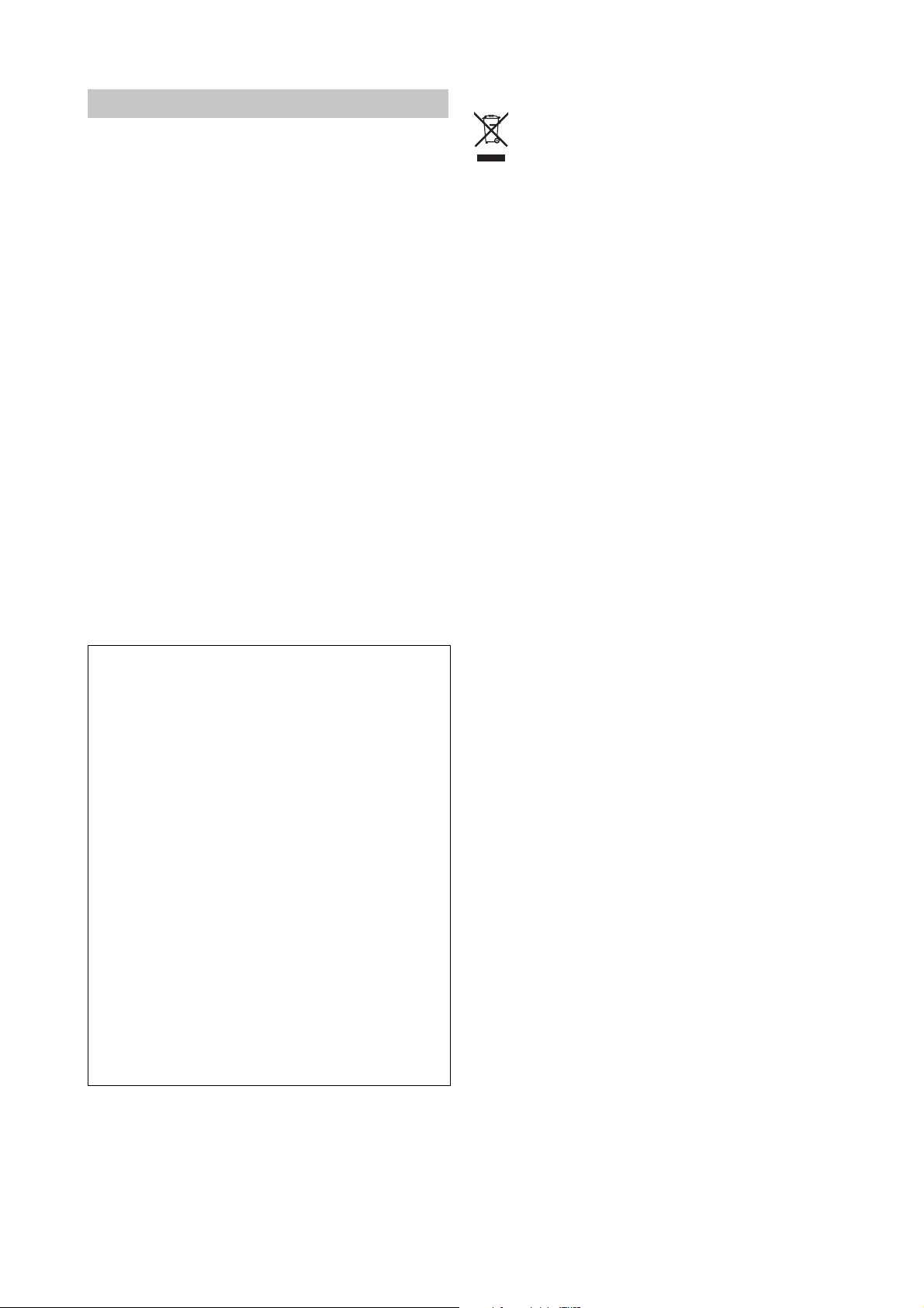
Parts and their functions
3
2
6
1
4
5
8
7
8. Connecting cable
This cable connects the keyboard assembly to the module.
Caution when adjusting the module
Please observe the following cautions in order to ensure
safe and correct assembly and disassembly.
Perform the steps in the correct order, making sure that each
part is oriented correctly.
Be careful not to pinch your hand while raising or lowering
the module.
Be sure that the module is powered-off when you connect
or disconnect the cable between the keyboard assembly and
the module. If you connect or disconnect this cable while
the power is on, the module may stop operating correctly.
Before you proceed, be sure to read and follow the “Safety
precautions” found earlier in this manual.
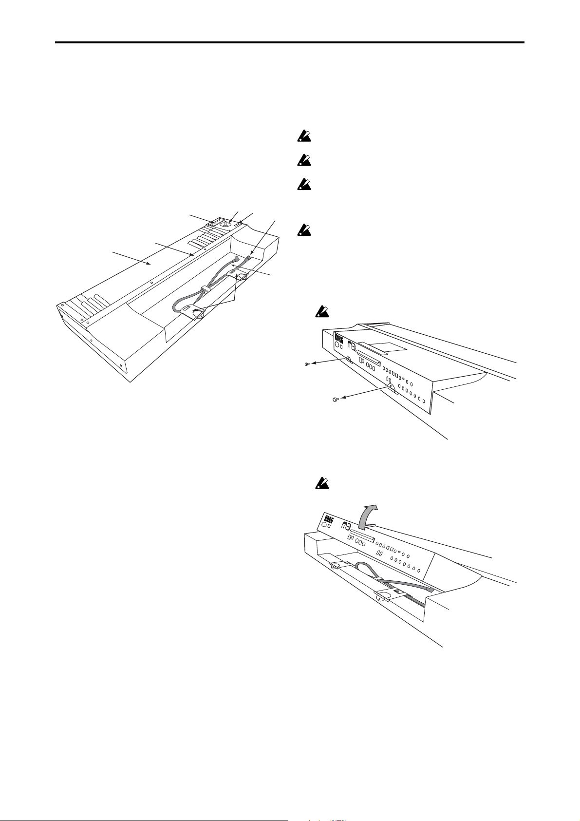
Raising the module
1. Remove the two screws (M3 x 8) that fasten the module’s
rear panel to the keyboard assembly.
Don’t lose these screws!
1. Keyboard
The keyboard features 61 semi-weighted keys.
2. Ribbon controller
By touching or rubbing your finger on this ribbon you can
control various program and effect parameters on the connected module.
3. Joystick
By moving the joystick up/down/left/right you can control various program and effect parameters on the connected module.
4. SW1/SW2
You can use these switches to control various program or
effect parameters on the connected module, or to turn the
joystick or ribbon controller’s Lock function on/off.
5. TO MODULE connector
One end of the connecting cable (8) will plug into this jack,
and the other end will plug into the module’s TO KYBD
port. When connected, you’ll be able to use the keyboard
assembly’s keyboard, joystick, ribbon controller and
switches to control the module.
M
U
S
I
C
W
O
R
K
S
T
A
T
I
O
N
/
S
A
M
P
L
E
R
2. Grasp the handle affixed to the module’s rear panel, and
gently tilt the module up.
Don’t tilt the module too far, since this will subject the
keyboard assembly to excessive strain.
M
U
S
I
C
W
O
R
K
S
T
A
T
I
O
N
/
S
A
M
P
L
E
R
6. Sound module retaining bar A (subsequently
“retaining bar A”)
This is used to lock the module to the keyboard assembly.
Four screws (M3 x 8) with it locks.
7. Sound module locking supports B (subsequently
“locking supports B”)
These supports lock the module to the keyboard assembly.
They also support the module when it is used in the tilted
position.
4
Page 5
3. As shown in the illustration, fold in the tab portion of
M
U
S
I
C
W
O
R
K
S
T
A
T
I
O
N
/
S
A
M
P
L
E
R
each locking support “B” that had been used to attach the
module to the keyboard assembly in step 1.
M
U
S
I
C
W
O
R
K
S
T
A
T
I
O
N
/
S
A
M
P
L
E
R
4. Raise each of the locking supports “B” to the appropriate
position as shown in the illustration below.
M
U
S
I
C
W
O
R
K
S
T
A
T
I
O
N
/
S
A
M
P
L
E
R
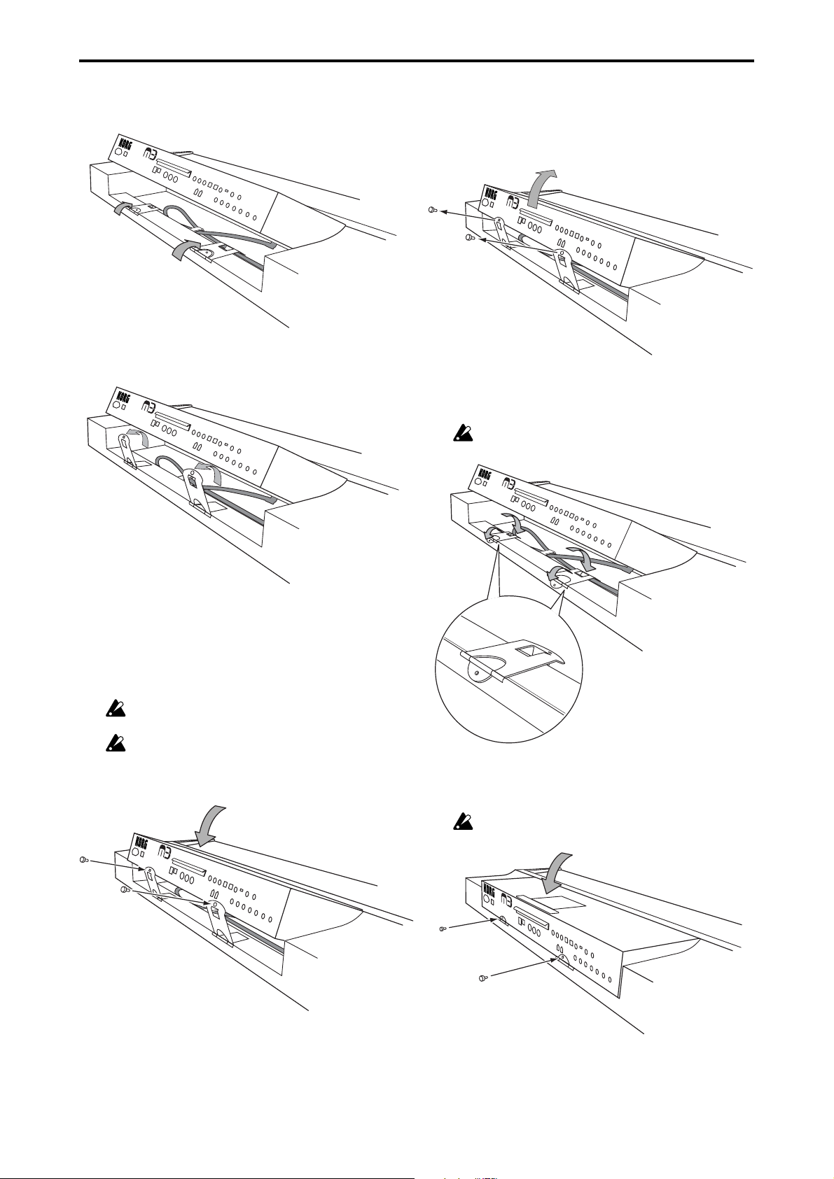
Lowering the module
1. Remove the two screws that fasten the module’s rear panel
to the keyboard assembly. Then grasp the handle affixed
to the module’s rear panel, and lift the module up.
M
U
S
IC
W
O
R
K
S
T
A
T
IO
N
/
S
A
M
P
L
E
R
2. While supporting the module with one hand, fold in each
of the locking supports “B”, and fold out the tab portion
that had been inside.
Be careful not to pinch your hand between locking supports “B” and the module.
M
U
S
I
C
W
O
R
K
S
T
A
T
I
O
N
/
S
A
M
P
L
E
R
5. Slowly lower the module onto the locking supports “B,”
ensuring that the screw hole of each locking support “B”
is aligned with the screw holes on the rear of the module.
At this time, the protrusion of each locking support “B”
will fit into a notch on the bottom of the module, helping
to hold the module in place as you perform the next step.
Be careful not to pinch your hand between locking supports “B” and the module.
If you move the keyboard assembly or apply excessive
force to the module before you’ve fastened the module
in place with the screws, the module may fall down,
causing injury.
M
U
S
I
C
W
O
R
K
S
T
A
T
I
O
N
/
S
A
M
P
L
E
R
3. Gently lower the module, and fasten the tab portion of
each locking support “B” to the module’s rear panel using the screws you removed in step 1.
Be careful not to pinch your hand between the module
and keyboard assembly.
5
Page 6
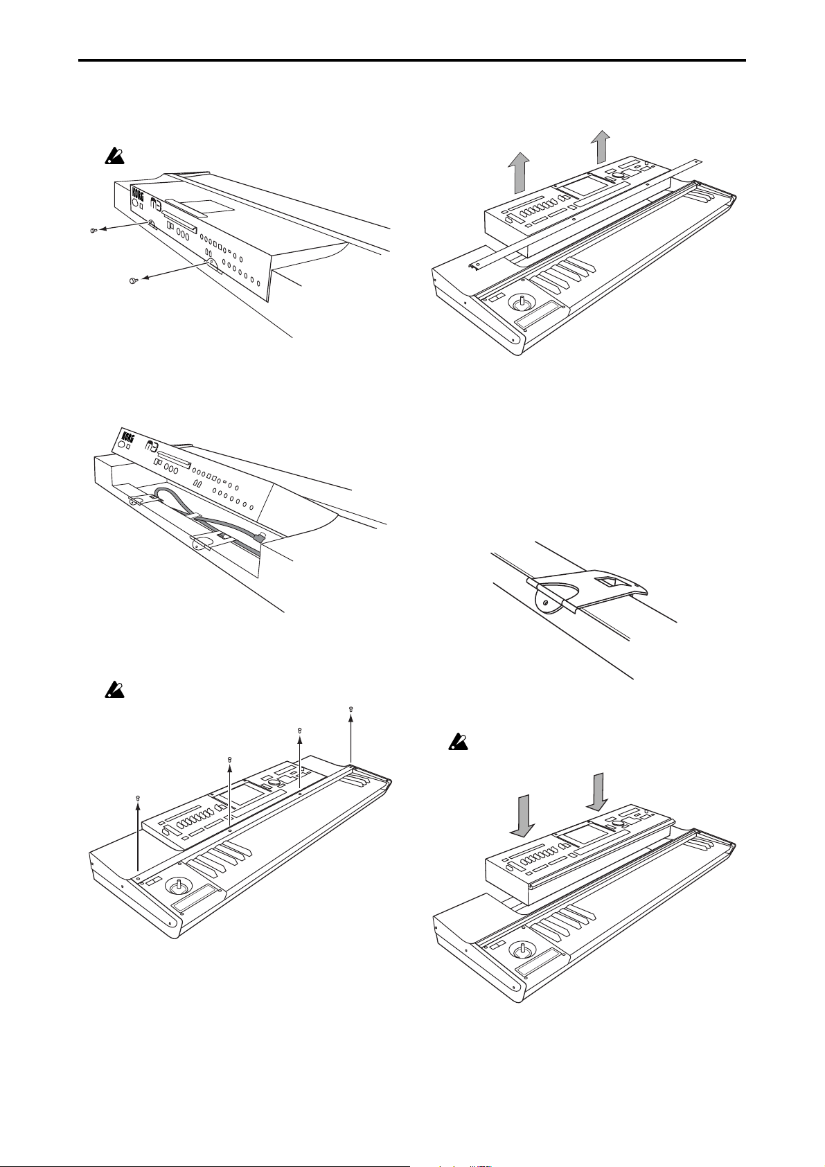
Removing the module
1. Remove the two screws that fasten the module’s rear panel
to the keyboard assembly.
Don’t lose these screws!
M
U
S
I
C
W
O
R
K
S
T
A
T
IO
N
/
S
A
M
P
L
E
R
2. While using one hand to raise the module, unplug the
cable (the “L” shaped plug) that’s connected to the TO
KYBD connector on the bottom of the module, and gently lower the module.
M
U
S
I
C
W
O
R
K
S
T
A
T
I
O
N
/
S
A
M
P
L
E
R
4. Raise the module slightly, and then use both hands to lift
it up, removing the module and retaining bar “A” from
the keyboard assembly.
5. Re-attach the retaining bar “A” using the screws you re-
moved in step 3. This will keep the screws and retaining
bar “A” safe for future use.
Attaching the module
1. Make sure that locking supports “B” are in the position
shown below, with the main supports folded in, and the
tab portion folded out. Remove retaining bar “A” from
the keyboard assembly.
3. Using your Philips (+) screwdriver, remove the four
screws from retaining bar “A” that holds the module to
the keyboard assembly.
Don’t lose these screws!
2. Using both hands, lift the module and gently place it on
the keyboard assembly as shown below.
Be careful not to pinch your hand between the module
and keyboard assembly.
6
Page 7

3. Making sure that retaining bar “A” is oriented correctly
as shown below, lay it gently over the module.
Align the screw holes of the keyboard assembly with the
screw holes of retaining bar “A,” and lightly fasten the
four screws using only your fingers. Then use your Philips
(+) screwdriver to firmly tighten all four screws.
Don’t tighten the screws by force if they are misaligned.
Doing so may damage the screws.
toward module
toward keyboard
Cross-section of
retaining bar “A”
Other cautions
Transportation
Before you transport the completed system (the keyboard
assembly and attached module), you must be sure to tighten
the two screws that fasten locking supports “B” to the module.
Specifications
Keyboard 61 notes
Controllers Joystick
Ribbon controller
SW1/SW2
Control connector TO MODULE connector
Dimensions (W x D x H) 1016 x 372 x 101 mm
40.0 x 14.6 x 3.9 inches
Weight 9.3 kg / 20.5 lbs.
* Appearance and specifications of this product are subject
to change without notice.
4. While using one hand to raise the module, connect the
included cable. Connect the “L” shaped plug of the cable
to the module’s TO KYBD connector, and connect the
straight plug to the TO MODULE connector of the keyboard assembly.
The included cable is only for the purpose of connecting the TO KYBD connector with the TO MODULE
connector. Do not connect it to any other connector.
5. Raise the tab portion of the locking supports “B” to the
position shown in the illustration below, and fasten the
module to the keyboard assembly using the two screws
you removed in step 1 of “Removing the module.”
M
U
S
IC
W
O
R
K
S
T
A
T
IO
N
/
S
A
M
P
L
E
R
7
Page 8

Précautions
Emplacement
L’utilisation de cet instrument dans les endroits suivants
peut en entraîner le mauvais fonctionnement.
• En plein soleil
• Endroits très chauds ou très humides
• Endroits sales ou fort poussiéreux
• Endroits soumis à de fortes vibrations
•A proximité de champs magnétiques
Interférences avec d’autres appareils électriques
Les postes de radio et de télévision situés à proximité peuvent par conséquent souffrir d’interférences à la réception.
Veuillez dès lors faire fonctionner cet appareil à une distance raisonnable de postes de radio et de télévision.
Maniement
Pour éviter de les endommager, manipulez les commandes et les boutons de cet instrument avec soin.
Entretien
Lorsque l’instrument se salit, nettoyez-le avec un chiffon
propre et sec. Ne vous servez pas d’agents de nettoyage
liquides tels que du benzène ou du diluant, voire des produits inflammables.
Conservez ce manuel
Après avoir lu ce manuel, veuillez le conserver soigneusement pour toute référence ultérieure.
Evitez toute intrusion d’objets ou de liquide
Ne placez jamais de récipient contenant du liquide près de
l’instrument. Si le liquide se renverse ou coule, il risque de
provoquer des dommages, un court-circuit ou une électrocution. Veillez à ne pas laisser tomber des objets métalliques dans le boîtier (trombones, par ex.).
* Les noms de sociétés, noms de produits et noms de for-
mats, etc. dans ce manuel sont des marques de fabrique
ou des mar-ques déposées de leurs propriétaires respectifs.
Notice concernant l’élimination du produit (UE seulement)
Si ce symbole “Poubelle barrée” est imprimé sur le
produit ou dans le manuel de l’utilisateur, vous
devez vous débarrasser du produit de la manière
appropriée. Ne jetez pas ce produit avec vos ordures ménagères. En vous débarrassant correctement du produit, vous préviendrez les dommages
environnementaux et les risques sanitaires. La méthode correcte d’élimination dépendra de votre
lieu d’habitation, aussi veuillez contacter les autorités locales concernées pour les détails.
8
Page 9

KKS (KORG Komponent System)
Cet instrument fait partie du KORG Komponent System.
Ce système extrêmement flexible loge tous les circuits de
génération de sons, tous les connecteurs externes et même
l’alimentation dans le module générateur de sons (dit le
“module”). Ce système vous permet de jouer avec le module horizontal ou incliné. De plus, le module peut être
extrait de l’instrument et utilisé comme module indépendant ou installé dans d’autres produits KKS.
Description et fonction des éléments
3
2
4
5
Précautions pour le réglage du module
Pour votre sécurité, veuillez prendre les précautions suivantes lors du montage et du démontage.
Effectuez les opérations dans le bon ordre en veillant à orienter correctement chaque élément.
Veillez à ne pas vous coincer la main en soulevant ou en
abaissant le module.
Veillez à mettre le module hors tension avant de connecter
ou de déconnecter le câble reliant le clavier au module. Si
vous établissez ou rompez la connexion alors que le module
est sous tension, vous risquez d’endommager ce dernier.
Avant de commencer, lisez et suivez les consignes données
dans la section “Précautions” au début de ce manuel.
1
6
8
7
1. Clavier
Le clavier dispose de 61 touches semi-pondérées.
2. Ruban
En touchant ou en frottant le ruban du doigt, vous pouvez
piloter divers paramètres de Programs et d’effets du module branché.
3. Joystick
En actionnant le joystick vers le haut, le bas, la gauche ou
la droite, vous pouvez piloter divers paramètres de
Programs et d’effets du module branché.
Relever le module
1. Retirez les deux vis (M3 x 8) fixant la face arrière du mo-
dule à l’ensemble clavier.
Ne perdez pas ces vis!
M
U
S
I
C
W
O
R
K
S
T
A
T
I
O
N
/
S
A
M
P
L
E
R
2. Attrapez la poignée en face arrière du module et soule-
vez doucement le module.
Ne soulevez pas trop le module car cela soumettrait
l’ensemble clavier à une contrainte excessive.
M
U
S
I
C
W
O
R
K
S
T
A
T
IO
N
/
S
A
M
P
L
E
R
4. SW1/SW2
Ces commutateurs vous permettent de piloter divers paramètres de Programs et d’effets du module branché ou d’activer et de couper la fonction “Lock” du joystick ou du ruban.
5. Prise TO MODULE
Une extrémité du câble de connexion (8) est branchée à cette
prise et l’autre extrémité à la prise TO KYBD du module.
Cette connexion vous permet d’utiliser le clavier, le joystick,
le ruban et les commutateurs pour piloter le module.
6. Barre de retenue “A” du module (appelée
“barre de retenue A”)
Cette barre rattache le module à l’ensemble clavier. Quatre
vis (M3 x 8) de fixation sont fournies.
7.
Fixations “B” du module (appelées “fixations B”)
Ces fixations attachent le module à l’ensemble clavier. Elles soutiennent également le module quand il est incliné.
8. Câble de connexion
Ce câble connecte le clavier au module.
9
Page 10

3. Comme le montre l’illustration, repliez l’onglet de cha-
que fixation “B” ayant servi à attacher le module à l’ensemble clavier à l’étape 1.
M
U
S
IC
W
O
R
K
S
T
A
T
I
O
N
/
S
A
M
P
L
E
R
Abaisser le module
1. Retirez les deux vis fixant la face arrière du module à l’en-
semble clavier. Prenez la poignée en face arrière du module et soulevez doucement le module.
M
U
S
IC
WO
R
K
S
TA
TI
ON
/
S
AM
PL
E
R
4. Relevez les fixations “B” et placez-les en position appro-
priée, comme le montre l’illustration ci-dessous.
M
U
S
IC
W
O
R
K
S
T
A
T
IO
N
/
S
A
M
P
L
E
R
5. Abaissez doucement le module sur les fixations “B” en
veillant à aligner l’orifice pour vis des fixations “B” avec
les orifices se trouvant en face arrière du module. Le relief des fixations “B” s’imbrique alors dans une ouverture pratiquée en face inférieure du module et contribue
à maintenir le module en place pour l’opération suivante.
Veillez à ne pas vous coincer la main entre les fixations
“B” et le module.
Si vous déplacez l’ensemble clavier ou exercez une pression excessive sur le module sans l’avoir fixé préalablement avec les vis, le module risque de tomber et de
blesser quelqu’un.
2. Tout en soutenant le module d’une main, repliez les fixa-
tions “B” et dépliez les onglets qui avaient été repliés.
Veillez à ne pas vous coincer la main entre les fixations
“B” et le module.
M
U
S
I
C
W
O
R
K
S
T
A
T
I
O
N
/
S
A
M
P
L
E
R
3. Abaissez doucement le module et fixez les onglets des
fixations “B” à la face arrière du module en utilisant les
vis retirées à l’étape 1.
Veillez à ne pas vous coincer la main entre le module et
l’ensemble clavier.
10
M
U
S
I
C
W
O
R
K
S
T
A
T
I
O
N
/
S
A
M
P
L
E
R
MUSIC WORKSTATION
/
SAMPLER
Page 11

Retirer le module
1. Retirez les deux vis fixant la face arrière du module à l’en-
semble clavier.
Ne perdez pas ces vis!
M
U
S
I
C
W
O
R
K
S
T
A
T
I
O
N
/
S
A
M
P
L
E
R
2. Soulevez le module d’une main et débranchez le câble (la
fiche en “L”) connecté à la prise TO KYBD en face inférieure du module puis abaissez doucement le module.
M
U
S
I
C
W
O
R
K
S
T
A
T
I
O
N
/
S
A
M
P
L
E
R
4. Relevez légèrement le module puis soulevez-le des deux
mains afin de retirer le module et la barre de retenue “A”
de l’ensemble clavier.
5. Rattachez la barre de retenue “A” avec les vis retirées à
l’étape 3. Vous êtes sûr ainsi de conserver les vis et la barre
de retenue “A” pour un usage ultérieur.
Fixer le module
1. Vérifiez que les fixations “B” sont dans la position illus-
trée ci-dessous: les supports principaux repliés et les onglets dépliés. Retirez la barre de retenue “A” de l’ensemble clavier.
3. Utilisez un tournevis cruciforme pour dévissez les qua-
tre vis de la barre de retenue “A” maintenant le module à
l’ensemble clavier.
Ne perdez pas ces vis!
2. Prenez le module des deux mains et placez-le doucement
sur l’ensemble clavier comme indiqué ci-dessous.
Veillez à ne pas vous coincer la main entre le module et
l’ensemble clavier.
11
Page 12

3.
Vérifiez que la barre de retenue “A” est orientée de la façon illustrée ci-dessous et posez-la sur le module.
Alignez les orifices pour vis de l’ensemble clavier avec les
orifices de la barre de retenue “A” et serrez doucement
les quatre vis avec les doigts. Utilisez ensuite le tournevis
cruciforme pour visser convenablement les quatre vis.
Ne serrez pas les vis de force si leur alignement n’est
bon. Cela les endommagerait.
vers le module
vers le clavier
Coupe de la barre
de retenue "A"
Autres précautions
Transport
Avant de transporter tout le système (l’ensemble clavier et
le module fixé), veillez à serrer les deux vis rattachant les
fixations “B” au module.
Fiche technique
Clavier 61 touches
Contrôleurs Joystick
Ruban
SW1/SW2
Prise de connexion Prise TO MODULE
Dimensions (L x P x H) 1016 x 372 x 101 mm
Poids 9,3 kg
* Ces caractéristiques et l’apparence du produit sont suscep-
tibles d’être modifiées sans avis préalable.
4. En soulevant le module d’une main, branchez le câble
fourni. Branchez la fiche en “L” du câble à la prise TO
KYBD du module et la fiche droite à la prise TO MODULE de l’ensemble clavier.
Le câble fourni ne sert qu’à relier la prise TO KYBD à
la prise TO MODULE. Ne le branchez à aucune autre
prise.
5. Relevez l’onglet des fixations “B” de la façon illustrée ci-
dessous et fixez le module à l’ensemble clavier avec les
deux vis que vous avez retirées à l’étape 1 de la section
“Retirer le module”.
12
M
U
S
I
C
W
O
R
K
S
T
A
T
IO
N
/
S
A
M
P
L
E
R
Page 13

Vor sichtsmaßnahmen
Aufstellungsort
Vermeiden Sie das Aufstellen des Geräts an Orten, an denen
• es direkter Sonneneinstrahlung ausgesetzt ist;
• hohe Feuchtigkeit oder Extremtemperaturen auftreten
können;
• Staub oder Schmutz in großen Mengen vorhanden sind;
• das Gerät Erschütterungen ausgesetzt sein kann.
• in der Nähe eines Magnetfeldes.
Störeinflüsse auf andere Elektrogeräte
Dieser kann bei in der Nähe aufgestellten Rundfunkempfängern oder Fernsehgeräten Empfangsstörungen
hervorrufen. Betreiben Sie solche Geräte nur in einem geeigneten Abstand von diesem Erzeugnis.
Bedienung
Vermeiden Sie bei der Bedienung von Schaltern und Reglern unangemessenen Kraftaufwand.
Reinigung
Bei auftretender Verschmutzung können Sie das Gehäuse
mit einem trockenen, sauberen Tuch abwischen. Verwenden Sie keinerlei Flüssigreiniger wie beispielsweise
Reinigungsbenzin, Verdünnungs- oder Spülmittel. Verwenden Sie niemals brennbare Reiniger.
Bedienungsanleitung
Bewahren Sie diese Bedienungsanleitung gut auf, falls Sie
sie später noch einmal benötigen.
Flüssigkeiten und Fremdkörper
Stellen Sie niemals Behältnisse mit Flüssigkeiten in der
Nähe des Geräts auf. Wenn Flüssigkeit in das Gerät gelangt,
können Beschädigung des Geräts, Feuer oder ein elektrischer Schlag die Folge sein. Beachten Sie, daß keinerlei
Fremdkörper in das Gerät gelangen.
* Die ubrigen in dieser Bedienungsanleitung erwahnten
Firmen-, Produkt-, Formatnamen usw. sind Warenzeichen
oder eingetra-gene Warenzeichen der rechtlichen
Eigentumer und werden ausdrucklich anerkannt.
Hinweis zur Entsorgung (nur EU)
Wenn dieses „durch gestrichener Müllkübel“ Symbol auf dem Produkt oder in der Bedienungsanleitung erscheint, müssen Sie dieses Produkt sachgemäß als Sondermüll entsorgen. Entsorgen Sie dieses Produkt nicht im Haushaltsmüll. Durch richtige Entsorgung verhindern Sie Umwelt- oder Gesundheitsgefahren. Die geltenden Vorschriften für
richtige Entsorgung sind je nach Bestimmungsland
unterschiedlich. Bitte informieren Sie sich bei der
zuständigen Behörde über die bei Ihnen geltenden
Vorschriften zur Entsorgung.
13
Page 14

KKS (KORG Komponent System)
Dieses Instrument ist Bestandteil des „KORG Komponent
Systems“. Dieses flexible System beruht auf einer Einheit
(im folgenden kurz das „Modul“ genannt), die außer der
Klangerzeugung auch alle externen Anschlüsse und selbst
die Stromversorgung enthält. Bei Bedarf kann das Modul
zum Spielen hochgeklappt werden. Das Modul lässt sich
übrigens komplett entfernen und als herkömmlicher Klangerzeuger bzw. gemeinsam mit anderen KKS-Produkten
nutzen.
Komponenten und Funktionen
3
2
6
1
4
5
8
7
7. Halterungen „B“ für das Modul (im folgenden
„Halterungen B“)
Mit diesen Halterungen wird das Modul an der Tastatureinheit verriegelt. Außerdem dienen sie als Stützen zum
Neigen des Moduls.
8. Anschlusskabel
Über dieses Kabel wird die Tastatur mit dem Modul verbunden.
Vorsicht beim Einstellen des Moduls
Im Sinne einer sicheren und richtigen Montage oder Demontage beachten Sie bitte folgende Punkte.
Führen Sie alle Schritte in der angegebenen Reihenfolge aus.
Alle Komponenten müssen richtig herum gehalten werden.
Seien Sie vorsichtig, um sich beim Anheben bzw. Absenken
des Moduls nicht die Finger zu klemmen.
Schalten Sie das Modul aus, bevor Sie das Verbindungskabel zwischen der Tastatureinheit und dem Modul anschließen bzw. lösen. Wenn Sie die Verbindung nämlich bei eingeschaltetem Modul herstellen bzw. lösen, verhält sich das
Modul nicht mehr erwartungsgemäß.
Lesen Sie sich zunächst die „Sicherheitsvorkehrungen“
durch.
1. Tastatur
Die Tastatur umfasst 61 leicht gewichtete Tasten.
2. Ribbon Controller
Mit Fingerbewegungen auf diesem Streifen können mehrere Program- und Effektparameter des angeschlossenen
Moduls in Echtzeit beeinflusst werden.
3. Joystick
Der Joystick lässt sich in alle Richtungen bewegen (auf/
ab/links/rechts). Auch damit können Program- und Effektparameter des angeschlossenen Moduls in Echtzeit
beeinflusst werden.
4. SW1/SW2
Mit diesen Tastern können verschiedene Program- und
Effektparameter des angeschlossenen Moduls in Echtzeit
beeinflusst werden. Außerdem kann man hiermit die
„Lock“-Funktion des Joysticks oder Ribbons aktivieren bzw.
ausschalten.
5. TO MODULE-Buchse
Hier muss das eine Ende des Verbindungskabels (8) angeschlossen werden. Das andere Ende dieses Kabels muss mit
dem TO KYBD-Port des Moduls verbunden werden. Nach
Herstellung der Verbindung können Sie die Tastatur, den
Joystick, den Ribbon Controller und die Taster zum Ansteuern des Moduls verwenden.
Anheben des Moduls
1. Lösen Sie die beiden Schrauben (M3 x 8), mit denen die
Modulrückseite an der Tastatureinheit befestigt ist.
Diese Schrauben dürfen Sie nicht verlieren!
M
U
S
I
C
W
O
R
K
S
T
A
T
I
O
N
/
S
A
M
P
L
E
R
2. Halten Sie den Griff auf der Modulrückseite fest und zie-
hen Sie das Modul behutsam hoch.
Ziehen Sie das Modul nie zu weit hoch, um die Tastatureinheit nicht zu beschädigen.
M
U
S
I
C
W
O
R
K
S
T
A
T
I
O
N
/
S
A
M
P
L
E
R
6. Halterungsleiste „A“ für das Modul (im
folgenden kurz „Halterungsleiste A“ genannt)
Hiermit kann das Modul an der Tastatureinheit befestigt
werden. Vier Schrauben (M3 x 8) für die Befestigung.
14
Page 15

3. Klappen Sie die Öse der beiden Halterungen „B“ wie in
M
U
S
I
C
W
O
R
K
S
T
A
T
I
O
N
/
S
A
M
P
L
E
R
der Abbildung gezeigt nach innen (die Ösen enthalten
normalerweise die Schrauben, die Sie in Schritt 1 gelöst
haben).
M
U
S
I
C
W
O
R
K
S
T
A
T
I
O
N
/
S
A
M
P
L
E
R
4. Heben Sie die Halterungen „B“ in die passende Position
(siehe die Abbildung).
M
U
S
IC
W
O
R
K
S
T
A
T
IO
N
/
S
A
M
P
L
E
R
Absenken des Moduls
1. Lösen Sie die beiden Schrauben, mit denen die Modul-
rückseite an der Tastatureinheit arretiert ist. Halten Sie
den Griff auf der Modulrückseite fest und ziehen Sie das
Modul behutsam hoch.
MUSIC W
O
RKS
TATIO
N
/
S
AMPLER
2. Stützen Sie das Modul mit einer Hand ab, klappen Sie
die Halterungen „B“ nach innen und ihre beiden Ösen
nach außen.
Gehen Sie behutsam vor, um sich nicht die Finger zwischen den Halterungen „B“ und dem Modul zu klemmen.
5. Senken Sie das Modul behutsam ab, bis es auf den Halte-
rungen „B“ aufliegt. Die Ösen der beiden Halterungen
„B“ müssen sich auf gleicher Höhe mit den Schrauben
der Modulrückseite befinden. Der Vorsprung der beiden
Halterungen „B“ passt in die Aussparungen an der
Modulunterseite und stützt das Modul während der
Ausführung des nächsten Schritts ab.
Gehen Sie behutsam vor, um sich nicht die Finger zwischen den Halterungen „B“ und dem Modul zu klemmen.
Wenn Sie die Tastatureinheit verschieben bzw. stark auf
das Modul drücken, bevor Sie es arretieren, kann das
Modul fallen und Verletzungen verursachen.
M
U
S
I
C
W
O
R
K
S
T
A
T
I
O
N
/
S
A
M
P
L
E
R
M
U
S
I
C
W
O
R
K
S
T
A
T
I
O
N
/
S
A
M
P
L
E
R
3. Senken Sie das Modul behutsam ab und befestigen Sie
die Öse der beiden Halterungen „B“ mit Hilfe der in
Schritt 1 entfernten Schrauben an der Modulrückseite.
Gehen Sie behutsam vor, um sich nicht die Finger zwischen dem Modul und der Tastatureinheit zu klemmen.
15
Page 16

Entnehmen des Moduls
1. Lösen Sie die beiden Schrauben, mit denen die Modul-
rückseite an der Tastatureinheit befestigt ist.
Diese Schrauben dürfen Sie nicht verlieren!
M
U
S
I
C
W
O
R
K
S
T
A
T
I
O
N
/
S
A
M
P
L
E
R
2. Heben Sie das Modul mit einer Hand an und ziehen Sie
den „L“-förmigen Stecker aus der TO KYBD-Buchse an
der Modulunterseite. Senken Sie das Modul anschließend
wieder ab.
M
U
S
I
C
W
O
R
K
S
T
A
T
I
O
N
/
S
A
M
P
L
E
R
4. Heben Sie das Modul leicht an und ziehen Sie es anschlie-
ßend mit beiden Händen hoch. Dabei löst sich auch die
Halterungsleiste „A“ von der Tastatureinheit.
5. Befestigen Sie die Halterungsleiste „A“ wieder mit den
in Schritt 3 entfernten Schrauben. So ist sichergestellt, dass
Sie sowohl die Schrauben als auch die Halterungsleiste
„A“ zu einem späteren Zeitpunkt erneut verwenden können.
Installieren des Moduls
3. Lösen Sie die vier Schrauben der Halterungsleiste „A“,
welche das Modul in der Tastatureinheit verankert, mit
einem Kreuzschlitzschraubenzieher (+).
Diese Schrauben dürfen Sie nicht verlieren!
1. Klappen Sie die Halterungen „B“ in die unten gezeigte
Position. Die Hauptarme müssen nach innen, die Ösen
hingegen nach außen geklappt sein. Lösen Sie die
Halterungsleiste „A“ von der Tastatureinheit.
2. Halten Sie das Modul mit beiden Händen fest, während
Sie es wie nachstehend gezeigt in die Tastatureinheit gleiten lassen.
Gehen Sie behutsam vor, um sich nicht die Finger zwischen dem Modul und der Tastatureinheit zu klemmen.
16
Page 17

3. Halten Sie die Halterungsleiste „A“ wie in der Abbildung
gezeigt, während Sie sie behutsam auf das Modul legen.
Ordnen Sie die Halterungsleiste „A“ so an, dass sich ihre
Bohrungen über jenen der Tastatureinheit befinden und
drehen Sie die Schrauben leicht mit den Fingern fest. Verwenden Sie anschließend einen Kreuzschlitzschraubenzieher (+), um die Schrauben komplett festzudrehen.
Wenn sich die Schrauben nur schwer festziehen lassen,
dürfen Sie keine Gewalt anwenden. Sonst werden die
Schrauben nämlich beschädigt.
5. Schieben Sie die Ösen der Halterungen „B“ in die unten
gezeigte Position und befestigen Sie das Modul mit den
beiden in Schritt 1 unter „Entnehmen des Moduls“ gelösten Schrauben an der Tastatureinheit.
M
U
S
I
C
W
O
R
K
S
T
A
T
I
O
N
/
S
A
M
P
L
E
R
Weitere Vorsichtsmaßnahmen
Transport
Vor dem Transport des gesamten Systems (Tastatureinheit
und Modul) müssen Sie sich davon überzeugen, dass die
beiden Schrauben, mit denen die Halterungen „B“ am
Modul befestigt sind, noch festsitzen.
Zum Modul
Zur Tastatur
Querschnitt der
Halterungsleiste "A"
4. Heben Sie das Modul mit einer Hand an und schließen
Sie mit der anderen das Kabel an. Verbinden Sie den „L“förmigen Stecker des Anschlusskabels mit der TO KYBDBuchse des Moduls. Der gerade Stecker muss an die TO
MODULE-Buchse der Tastatureinheit angeschlossen werden.
Das beiliegende Kabel eignet sich nur für die Verbindung der TO KYBD- mit der TO MODULE-Buchse.
Schließen Sie es nie an eine andere Buchse an.
Technische Daten
Tastatur 61 noten
Spielhilfen Joystick
Ribbon Controller
SW1/SW2
Steueranschluss TO MODULE-Buchse
Abmessungen (B x T x H) 1016 x 372 x 101 mm
Gewicht 9,3 kg
* Änderungen der technischen Daten und Funktionen ohne
vorherige Ankündigung vorbehalten.
17
Page 18

IMPORTANT NOTICE TO CONSUMERS
This product has been manufactured according to strict specifications and voltage requirements that are applicable in
the country in which it is intended that this product should be used. If you have purchased this product via the internet,
through mail order, and/or via a telephone sale, you must verify that this product is intended to be used in the country in
which you reside.
WARNING: Use of this product in any country other than that for which it is intended could be dangerous and could
invalidate the manufacturer’s or distributor’s warranty.
Please also retain your receipt as proof of purchase otherwise your product may be disqualified from the
manufacturer’s or distributor’s warranty.
REMARQUE IMPORTANTE POUR LES CLIENTS
Ce produit a été fabriqué suivant des spécifications sévères et des besoins en tension applicables dans le pays où ce
produit doit être utilisé. Si vous avez acheté ce produit via l’internet, par vente par correspondance ou/et vente par
téléphone, vous devez vérifier que ce produit est bien utilisable dans le pays où vous résidez.
ATTENTION: L’utilisation de ce produit dans un pays autre que celui pour lequel il a été conçu peut être dangereuse et
annulera la garantie du fabricant ou du distributeur. Conservez bien votre récépissé qui est la preuve de votre achat,
faute de quoi votre produit ne risque de ne plus être couvert par la garantie du fabricant ou du distributeur.
WICHTIGER HINWEIS FÜR KUNDEN
Dieses Produkt wurde unter strenger Beachtung von Spezifikationen und Spannungsanforderungen hergestellt, die im
Bestimmungsland gelten. Wenn Sie dieses Produkt über das Internet, per Postversand und/oder mit telefonischer
Bestellung gekauft haben, müssen Sie bestätigen, dass dieses Produkt für Ihr Wohngebiet ausgelegt ist.
WARNUNG: Verwendung dieses Produkts in einem anderen Land als dem, für das es bestimmt ist, verwendet wird,
kann gefährlich sein und die Garantie des Herstellers oder Importeurs hinfällig lassen werden. Bitte bewahren Sie
diese Quittung als Kaufbeleg auf, da andernfalls das Produkt von der Garantie des Herstellers oder Importeurs
ausgeschlossen werden kann.
2007 KORG INC.
4015-2 Yanokuchi, Inagi-city, Tokyo 206-0812 Japan
1902 COH
Printed in Japan
 Loading...