

Page 1
1E
Page 2

KARMA™ (Kay Algorithmic Realtime Music Architecture) Technology has been licensed from Stephen Kay, and
is protected by U.S. Patents 5,486,647, 6,084,171, 6,087,578,
6,103,964, 6,121,532, and 6,121,533. Other patents pending.
KARMA™, the KARMA Logo, Generated Effect™ (GE),
Melodic Repeat™, Direct Index™, Manual Advance™,
and SmartScan™ are trademarks of Stephen Kay, Karma
Lab LLC, www.karma-lab.com. This manual copyright
2000-2001 by KORG Inc. and Stephen Kay. All rights
reserved.
Screen shots from the KARMA software that appear
throughout this guide are
Karma Lab LLC. Used by permission. All rights reserved.
1994-2001 by Stephen Kay,
©
©
Page 3
About this manual
The “KARMA GE Guide” explains the GE parameters of
the KARMA function built into this KARMA Music
Workstation, organized according to the groups that make
up the Generated Effects.
The KARMA Music Workstation provides more than one
thousand preset GE’s (Generated Effects). For each GE,
up to sixteen of the more than four hundred GE parameters have been selected for optimal control from the
KARMA Music Workstation.
The GE parameters and ranges that can be controlled will
differ for each GE.
Some GE parameters are related to other parameters, and
are affected by them. In this case, the parameters that are
producing the effect may not always be displayed, since
they may already be preset for that GE.
Furthermore, the KARMA-related parameters in pages
6.1–6.4 of each mode may also function differently or not
at all, depending on the settings of these GE parameters.
Some of the internal parameters of each GE are displayed
in the Voice Name List. (☞VNL)
In order to explain the GE parameters, this document
includes example settings using these parameters that
cannot be viewed or set, and examples of pattern settings
using pattern grids that cannot be displayed in the LCD
screen of the KARMA Music Workstation.
How to read the “GE Guide”
The GE’s (Generated Effects) are organized into 14 groups.
Each group has GE parameters. (☞p.3 diagram)
The 6.3: Ed-KARMA GE (or KARMA GE) page shows the
group name, parameter name, and parameter value of the
GE parameters.
You can use the 6.3: Ed-KARMA GE (or KARMA GE) page
to check the group name and parameter name of the GE
parameter you wish to look up, and then find it in the GE
Guide.
Here’s an example from Program mode.
Access the PROG 6.3: Ed-KARMA GE page, and display
the GE parameters in the LCD screen. (☞PG p.32 PROG
6.3: Ed-KARMA)
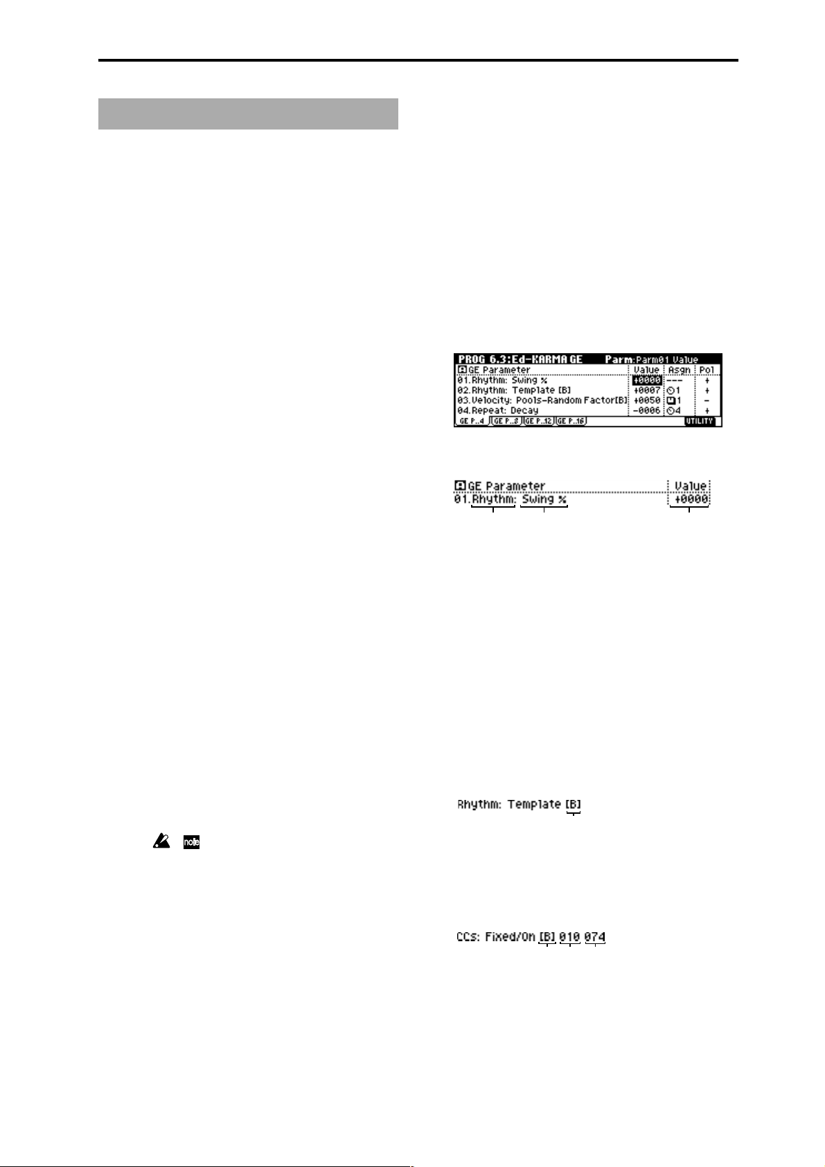
The GE parameters displayed in the LCD screen show the
group name and parameter name.
Group name Parameter name Parameter value
Printing conventions in this document
Abbreviations for the owner’s manuals: PG, VNL
The included owner’s manuals are abbreviated as follows.
PG: Parameter Guide
VNL: Voice Name List
Parameters “ ”
Parameters are enclosed in “double quotation marks.”
Bold type
Parameter values are printed in bold type.
Bold type is also used for text that is being emphasized.
☞p. ■ ■, ☞PG p. ■ ■
These respectively indicate a GE Guide page or Parameter
Guide page to which you can refer.
Symbols ,
These symbols respectively indicate cautions or advice.
Illustrations in this manual
Pattern grid screens etc. in this manual are provided to
supplement the explanation.
They are not displayed in the LCD screen of the KARMA
Music Workstation.
For example in the case of 01. Rhythm: Swing %, the
group is Rhythm Group and the parameter is “Swing %.”
The explanation for “Swing %” is given on p.13 “Rhythm
Group”Swing %.”
The parameter value is displayed by “Value” at the right
of the parameter name.
The default value and editing range of the parameter is
preset for each GE. Depending on the selected GE, the
same GE parameter may have a different default value
and a different editing range.
For some GE parameters, the following information is
displayed in addition to the parameter name.
• Parameter name [Phase]
This indicates the phase for which the parameter is valid.
(For details refer to p.53)
Display example
[Phase]
• CCs: parameter name #No. #No.
Parameters of the CCs group also indicate the MIDI
message that is controlled by the CCs. (For details refer to
p.53)
Display example
[Phase]
#No. #No.
MIDI-related listings
CC# is an abbreviation for Control Change Number.
iii
Page 4

• Env: parameter name [ENV] #No. #No. #No.
Parameters of the Env (Envelope) Group also indicate the
envelope for which that GE parameter is valid, and
indicate the parameter or MIDI message that is controlled
by the Envelope. (For details refer to p.53)
Display example
[Env] #No.
• Drum: parameter name [Pat]
Parameters of the Drum group also indicate the drum
pattern for which that GE parameter is valid. (Some
parameters in the Drum Group that are not related to the
individual Drum Patterns will not display this information.) (For details refer to p.53)
Display example
[Pat]
iv
Page 5

Table of Contents
About KARMA................................. 2
Overview................................................. 2
Theory Of Operation.............................. 2
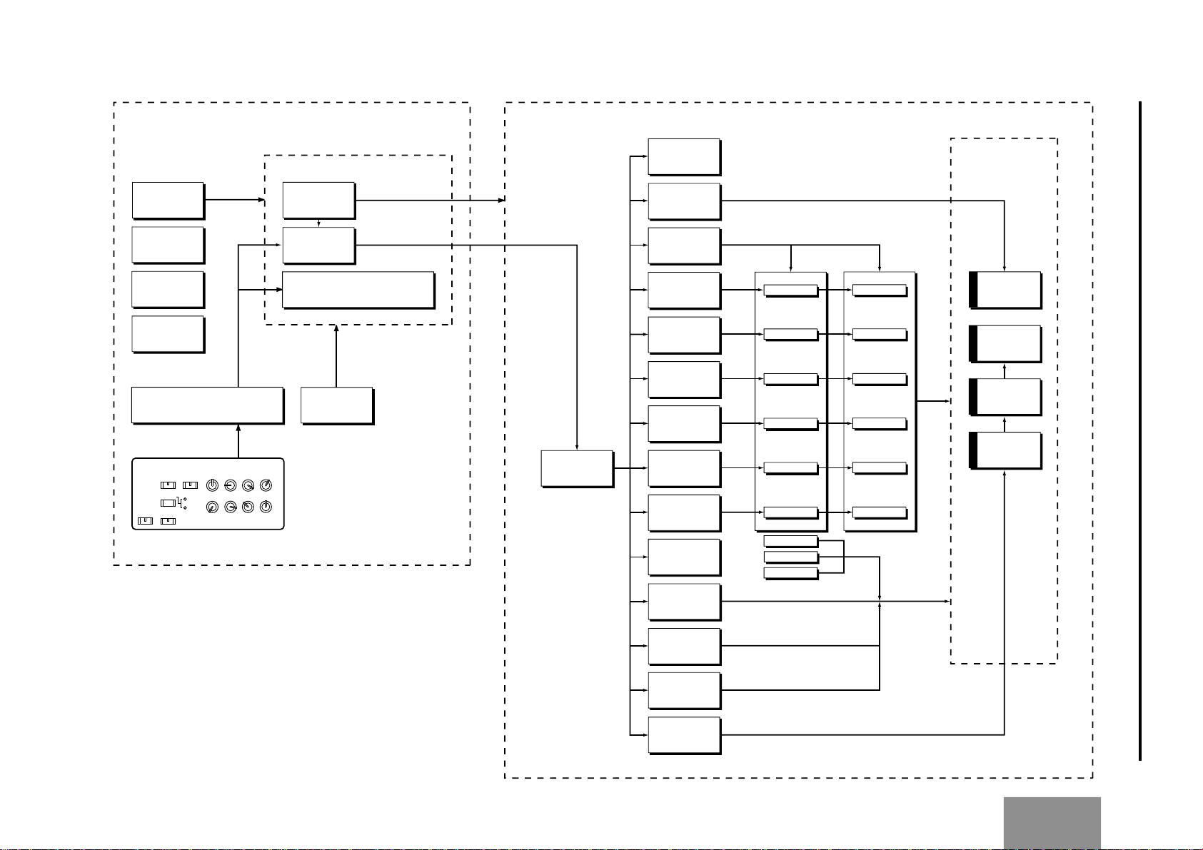
KARMA Architecture (Diagram) ........... 3
GE (Generated Effect) Group ............ 4
Overview................................................. 4
Octave Transpose ............................................. 11
Oct/5th Transpose ............................................ 11
Events............................................................... 11
TSig Numerator ................................................11
TSig Denominator ............................................ 11
Beginning Offset % .......................................... 11
End Offset % .................................................... 11
End Loop Parameters.......................... 11
End Loop On/Off .............................................. 11
End Loop Start Step ......................................... 11
End Loop Length ..............................................11
GE Global Parameters........................... 4
GE Type .............................................................. 4
Gate Type ........................................................... 4
Gate CC Number................................................ 5
Note Series Group........................... 6
Overview................................................. 6
Parameters ............................................. 6
Note Type............................................................ 6
Input Sort ............................................................6
Inversion ............................................................. 7
Replications ........................................................ 7
Max ..................................................................... 7
Symmetry ........................................................... 7
Interval ................................................................ 7
Chord Shift ......................................................... 7
Wrap Bottom ...................................................... 7
Wrap Top ............................................................ 7
Voicing ................................................................ 7
Filter Dupes ........................................................ 8
Filter Fixed .......................................................... 8
Filter Template .................................................... 8
Phase Group ................................... 9
Overview................................................. 9
About Phase Patterns ........................... 9
General Parameters............................... 9
Total Steps.......................................................... 9
Start % ................................................................ 9
Start Mode ..........................................................9
Length Mode ...................................................... 9
Cycle Mode ...................................................... 10
Phase Specific Parameters................. 10
Direction ........................................................... 10
Transpose .........................................................10
Pattern Parameters .............................. 12
Pattern Items ....................................................12
Pattern Step1…16 ............................................ 12
Template Parameters .......................................12
Template (All Steps) .........................................12
Template Steps 1…4 ........................................ 12
Template Steps 5…8 ........................................ 12
Template Steps 9…12 ...................................... 12
Template Steps 13…16 .................................... 12
Rhythm Group............................... 13
Overview............................................... 13
About Rhythm Patterns....................... 13
Global Parameters............................... 13
Humanize ......................................................... 13
Swing Note Value ............................................. 13
Swing %............................................................ 13
Swing Use Multiplier......................................... 13
Pattern Grid & Associated Parameters .....
Rhythm Pattern ........................................ 14
Random Weighting Parameters - Pools ....
Pools-Random Factor....................................... 14
Pools-WeightingCurve (Pools-Weighting Curve) .....
Random Weighting Parameters - Ties ...
Ties-Random Factor......................................... 15
Ties-Weighting Curve....................................... 15
Associated Parameters....................... 15
Rhythm Multiplier.............................................. 15
Straight Multipliers............................................ 15
Straight/Trip Mults ............................................ 15
Strt/Dot/Trip Mults ............................................ 16
Template ........................................................... 16
14
14
14
15
v
Page 6

Duration Group ............................. 17
Cluster Group................................ 22
Overview............................................... 17
About Duration Patterns ..................... 17
Pattern Grid & Associated Parameters .....
Duration Pattern....................................... 17
Associated Parameters ........................... 17
Duration Mode .................................................. 17
Duration Value .................................................. 18
Random Weighting Parameters - Pools ....
Pools-Randm Factor (Pools-Random Factor) ..........
Pools-Weight Curve (Pools-Weighting Curve) ....
Random Weighting Parameters - Ties .......
Ties-Randm Factor (Ties-Random Factor) ......18
Ties-Weight Curve (Ties-Weighting Curve) ..... 18
17
18
18
18
18
Associated Parameters....................... 18
Template ........................................................... 18
Index Group ................................. 19
Overview............................................... 19
About Index Patterns........................... 19
Pattern Grid & Associated Parameters .....
19
Overview............................................... 22
About Cluster Patterns........................ 22
Global Parameters............................... 22
Strum ................................................................ 22
Pattern Grid & Associated Parameters .....
Cluster Pattern ......................................... 22
22
Random Weighting Parameters.......... 22
Pools-Random Factor....................................... 22
Pools-Weight Curve (Pools-Weighting Curve).........
23
Associated Parameters....................... 23
Template ...........................................................23
Velocity Group .............................. 24
Overview............................................... 24
About Velocity Patterns....................... 24
Global Parameters............................... 24
Velocity Mode ................................................... 24
Velocity Value ................................................... 24
Randomize Bottom ........................................... 24
Randomize Top................................................. 24
Index Pattern ............................................ 19
Associated Parameters ........................... 19
Pattern Type ..................................................... 19
Random Walk Max Step ................................... 19
Random Weighting Parameters.......... 20
Pools-Random Factor....................................... 20
Pools-Weighting Curve ..................................... 20
Associated Parameters....................... 20
Cluster Mode ....................................................20
Invert ................................................................. 20
Double .............................................................. 21
Double Amount................................................. 21
Template ........................................................... 21
Pattern Grid & Associated Parameters .....
Velocity Pattern ........................................ 24
24
Random Weighting Parameters.......... 25
Pools-Randm Factor (Pools-Random Factor) ..........
Pools-Weight Curve (Pools-Weighting Curve) ....
25
25
Associated Parameters....................... 25
Cluster Mode ....................................................25
Scale ................................................................. 25
Template ...........................................................25
CCs Group .................................... 26
Overview............................................... 26
About CC Patterns............................... 26
Pattern Grid & Associated Parameters .....
CC Pattern ................................................ 26
Associated Parameters ........................... 26
Fixed/On ...........................................................26
Pattern Type .....................................................26
Polarity.............................................................. 26
26
vi
Page 7

Random Weighting Parameters.......... 27
Pools-Rand Fact (Pools-Random Factor) ................
Pools-WeightCrv (Pools-Weighting Curve) ...... 27
27
Global Parameters............................... 27
CC-A .................................................................27
CC-B .................................................................27
Associated Parameters....................... 27
Cluster Mode ....................................................27
Template ...........................................................27
Env (Envelope) Group .................... 28
Overview............................................... 28
About Envelopes ................................. 28
Parameters ........................................... 28
Env On/Off (Envelope On/Off) ......................... 28
Env Type (Envelope Type) ................................ 28
Start Level ........................................................ 29
Attack Time .......................................................29
Attack Lvl (Attack Level) ................................... 29
Decay Time....................................................... 29
Sustain Lvl (Sustain Level)...............................29
Rel. Time (Release Time)................................. 29
Rel. Level (Release Level) ............................... 29
Amp Amount (Amplitude Amount) ................... 29
Time Scale ....................................................... 29
Att Smooth (Attack Smooth) ............................ 29
Loop Mode ....................................................... 29
Tempo Reltv (Tempo Relative) ......................... 30
Note Trig (Note Trigger) .................................... 30
Level Combinations............................. 30
Sta/Att Lvl (Start/Attack Level) .........................30
Sta/Sus Lvl (Start/Sustain Level) ..................... 30
Sta/Rel Lvl (Start/Release Level) ..................... 30
Att/Sus Lvl (Attack/Sustain Level).................... 30
Att/Rel Lvl (Attack/Release Level) ................... 30
Sus/Rel Lvl (Attack/Release Level)..................30
St/At/Su Lvl (Start/Attack/Sustain Level) ......... 30
St/At/Rl Lvl (Start/Attack/Release Level) .........30
St/Su/Rl Lvl (Start/Sustain/Release Level) ......31
At/Su/Rl Lvl (Attack/Sustain/Release Level) .... 31
All Levels .......................................................... 31
Time Combinations ............................. 31
Att/DecTime (Attack/Decay Time) .................... 31
Att/RelTime (Attack/Release Time)..................31
Dec/RelTime (Decay/Release Time)................ 31
All Times ........................................................... 31
Repeat Group (Melodic Repeat) ...... 32
Overview............................................... 32
General Parameters............................. 32
Rhythm Value ................................................... 32
Straight Rhythm Values .................................... 32
Dotted Rhythm Values...................................... 32
Triplet Rhythm Values....................................... 33
Selected Rhythm Values .................................. 33
Use Swing ........................................................ 33
Repetitions ....................................................... 33
Decay................................................................33
Initial Volume .................................................... 33
Transpose .........................................................33
Chord Shift ....................................................... 33
Stop Mode ........................................................ 33
Rebound ...........................................................34
Tempo Lock ...................................................... 34
Range Parameters ............................... 34
Range Mode .....................................................34
Wrap Bottom .................................................... 34
Wrap Top .......................................................... 34
Vel. Range Bottom............................................35
Vel. Range Top ................................................. 35
Real-Time Parameters......................... 35
Duration Mode (RT).......................................... 35
Duration Value (RT).......................................... 35
Key Mode (RT) ................................................. 35
Chord Quantize (RT) ........................................ 35
Bend Group .................................. 37
Overview............................................... 37
General Parameters............................. 37
On/Off ...............................................................37
Amount ............................................................. 37
Shape ............................................................... 37
Alternation ........................................................ 38
Step .................................................................. 38
Length............................................................... 38
Fixed-ms ...........................................................38
Start .................................................................. 38
End ................................................................... 38
Width ................................................................ 38
Drum Bend Mode ............................................. 39
Bend Range ..................................................... 39
vii
Page 8

Real-Time Parameters......................... 39
Key Mode (RT) ................................................. 39
Direction (RT) ...................................................39
Rel. Delay Length (RT) ..................................... 39
Rel. Delay Damping (RT) ................................. 39
Drum Group.................................. 40
Overview............................................... 40
Direct Index Group ........................ 44
Overview............................................... 44
General Parameters............................. 44
Index Shift......................................................... 44
Trill Mode .......................................................... 44
Held Note Trig Mode ......................................... 44
Transpose .........................................................45
Vel. Sensitivity .................................................. 45
About Drum Patterns........................... 40
Pattern Editing Grid &
Associated Parameters...................... 40
Drum Pattern ............................................ 40
Associated Parameters ........................... 40
Play On/Off ....................................................... 40
On/Off Combinations........................................ 40
Row1…7 Note .................................................. 41
Row1…7 Vel. Offset ......................................... 41
Rhythm Multiplier.............................................. 41
Straight Multiplier ............................................. 41
Straight/Trip Mults ............................................ 41
Strt/Dot/Trip Mults ............................................ 41
Velocity Offset .................................................. 41
Velocity Scale ................................................... 41
Pattern Transpose ............................................ 41
Octave Transpose ............................................. 41
Oct/5th Transpose ............................................ 42
Use Riff Length................................................. 42
Random Weighting Parameters - Pools ....
Pools-Random Factor....................................... 42
Pools-WeightingCurve (Pools-Weighting Curve) .....
42
42
Duration Parameters ........................... 45
Duration Control ............................................... 45
Duration Mode .................................................. 45
Duration ms ...................................................... 45
Repeat Parameters .............................. 45
Melodic Rpt On/Off........................................... 45
Bend Parameters ................................. 46
Bend On/Off ..................................................... 46
Bend Amount .................................................... 46
Bend Shape ...................................................... 46
Bend Alternation ............................................... 46
Bend Step ......................................................... 46
Bend Length ..................................................... 47
Bend Fixed-ms ................................................. 47
Bend Start ........................................................ 47
Bend End .......................................................... 47
Bend Width ....................................................... 47
Appendices ................................... 48
Using Auto-Bend ................................. 48
Next Note/Previous Note Bends............. 48
viii
Random Weighting Parameters - Rests ....
Rests-Random Factor ...................................... 42
Rests-WeightingCurve (Rests-Weighting Curve) ....
42
42
Associated Parameters....................... 43
Pools/Poly ......................................................... 43
Track Keyboard ................................................. 43
NTT (Note Table Transposition) ........................43
Link To Next ...................................................... 43
Wrap Bottom .................................................... 43
Wrap Top .......................................................... 43
Template ........................................................... 43
Length Of Bends...................................... 48
The Different Bend Shapes..................... 49
Random Weighting Curves................. 50
Weighting Curve Shapes and
Their Effects ............................................ 50
Comparison of Exponential and
Logarithmic Curves ................................ 51
How GE parameter names are
displayed ............................................. 53
Page 9

About KARMA
GE Group
Note Series Group
Phase Group
Velocity Group
CCs Group
Env (Envelope) Group
Repeat Group
Rhythm Group
Duration Group
Index Group
Cluster Group
Bend Group
Drum Group
Direct Index Group
Appendices
Page 10

About KARMA
Overview
KARMA stands for Kay Algorithmic Realtime Music
Architecture, named after its inventor, Stephen Kay.
The KARMA function generates MIDI data, using many
different complex algorithms seamlessly integrated to
provide a powerful “music generation engine”. Based on
the notes and chords you play, KARMA generates phrases
and patterns in real-time, generating not just notes but
MIDI control data as well. The KARMA architecture allows
the various algorithms to be reconfigured and varied in
realtime, as you play them.
For example, you can create spectacular cascades of
complex interweaving notes, techno arpeggios and effects,
dense rhythmic and melodic textures, natural sounding
glissandos for acoustic instrument programs, guitar
strumming and finger-picking simulations, random
effects, auto-accompaniment effects, gliding and swooping portamento and pitch bend effects, and new sound
design possibilities. KARMA lets you produce phrases and
patterns far beyond the level provided by conventional
arpeggiators or pattern playback functions.
randomized grooves and accompaniment backings. Up
until now there have been two basic types of backing
track generation. The traditional method used in all autoaccompaniment keyboards is a system which analyzes
notes played on a keyboard (chord recognition) and then
plays back patterns stored in memory through transposition tables. The second method is the one used by some
algorithmic software products that create new patterns
each time the algorithm is called. In general, the first
method is static and repetitive, while the second method
cannot be modified in real-time.
KARMA combines the algorithmic diversity of the second
method with the real-time control and immediate access
of the first method to create a new form of interactive
groove generation, where the user is in more direct
control, since what is produced is directly related to which
notes are pressed. Furthermore, extensive aspects of the
rhythm, velocity, chord size and other parameters can be
randomly varied in real-time to allow the user to control
the complexity and density of the resulting performance.
The new KARMA function is the heart of the KARMA Music
Workstation.
Whether you are playing programs or combinations,
performing with the KARMA Realtime Controls knobs,
switches, and [CHORD TRIGGER] keys, giving a live
performance, or recording new music using the onboard
sequencer, you can take full advantage of the KARMA
function at any time.
Theory Of Operation
A performance of a musical phrase can be thought of as
having many different “attributes” which determine the
overall effect of the resulting music. For example, a
musical phrase has a “rhythm” attribute, which is the
rhythm with which the notes are being played. The
number of notes (“chords”) being played at the same time
in various places of the musical phrase could be called a
“cluster” attribute. The velocity (accent) with which the
notes are played is a “velocity” attribute. The spatial
location in a stereo field where the notes are played is a
“pan” attribute, etc.
Typically, music that has been recorded or sequenced has
all of these attributes predetermined and fixed in relation
to each other. A specific note is to be played with a specific
rhythmic value for a specific period of time, at a specific
volume level, at a specific location in a stereo field, with
the sound of a specific musical instrument, and these
relationships remain fixed no matter how many times you
play back the performance. For example, in most if not all
auto-accompaniment instruments, to achieve a variation
in the accompaniment pattern the instrument essentially
switches to a different pre-recorded sequence of musical
events (again with specific relationships that are fixed in
the data).
In KARMA, every aspect of a musical phrase has been
separated into independently controllable attributes. Each
of these attributes is controlled by a separate group of
parameters, which can be individually varied or changed
in groups by the user in real-time as the music is being
generated; or changed all at once with the selection of a
program or combination.
KARMA can also be used to generate infinitely variable
2
Page 11
1
2
3
4
5
6
7
8
12
SCENE
1
2
ON/OFF LATCH
KARMA REALTIME CONTROLS
GE
Note Series
Phase
Rhythm
Duration
Index
Cluster
Velocity
CCs
Envelope
Repeat
Bend
Direct Index
Drum
Group / Parameters
GE Parameters
Env 2
Env 1
Env 3
Phase 1
Phase 1
Phase 1
Phase 1
Phase 1
Phase 1
Phase 2
Phase 2
Phase 2
Phase 2
Phase 2
Phase 2
Note
Series
Drum
Pattern 1
Drum
Pattern 2
Drum
Pattern 3
DATA to be
read out of
GE
(Generated Effect)
KARMA
Module A
KARMA
Module B
KARMA
Module C
KARMA
Module D
GE Parameters
KARMA Module Parameters
GE Number
KARMA Module
RT Parm (Realtime Parameters)
Dynamic MIDI
Program : KARMA Module A
Combination/Song/Song Play Mode: KARMA Module A/B/C/D
KARMA Architecture (Diagram)
3
About
KARMA
Page 12
GE (Generated Effect) Group
Overview
The phrases and patterns produced by a KARMA module
are generated by a GE (Generated Effect).
Based on note data from the keyboard or external MIDI
device, the GE uses various internal parameters to control
how the note data will be developed, and how rhythm,
chord structure, and velocity etc. will be controlled to
generate a phrase or pattern. MIDI control changes and
pitch bend data can also be generated in synchronization
with the phrase or pattern, making it possible to create
phrases and patterns in which the tone color and note
pitches change independently.
This instrument contains over 1000 preset GEs that can be
used with a wide range of instruments, playing styles, and
musical genres.
GE Global Parameters
GE Type [0…3]
0: Generated-Riff 2: Generated-Drum
1: Generated-Gated 3: Real-Time
Chooses one of several different overall algorithm
configurations for the current Generated Effect. This
setting determines some basic modes of operation, and
also which parameters are available within the various GE
Groups.
0: Generated-Riff
Produces riffs, arpeggios, and chord clusters based on the
notes given as input source material. The notes are
expanded, transposed, replicated, and otherwise altered
to form a Note Series by the parameters in the Note Series
Group. Effects are generated based on the Rhythm Pattern
as it relates to the clock source or tempo envelope.
1: Generated-Gated
Retriggers the actual notes given as input source material
according to the parameters. While the Note Series is still
created, the generated notes do not extend beyond the
actual notes played. Effects are generated based on the
Rhythm Pattern as it relates to the clock source or tempo
envelope. The notes themselves can be generated, or a
sustained set of notes which is then “sliced and diced” by
a selected controller value. This can be used to simulate
several types of popular techno effects, such as gating a
synth pad with a hi-hat track and an external audio gate/
compressor.
2: Generated-Drum
Uses special patterns of predetermined pitches rather than
the Note Series to generate notes. These can be used not
only to create Drum Patterns, but to create controlled
musical patterns. Effects are generated based on the
Rhythm Pattern as it relates to the clock source or tempo
envelope. Riffs based on the notes in the Note Series can
be applied as pitch bend, to create wave-sequence and
other unique effects, and also to control other things such
as the length of Phases.
3: Real-Time
Different from the previous types in that the actual notes
given as input source material are used as a starting point,
from which effects are generated over time according to
time calculations. Examples include glissandos and
arpeggios which start with the note(s) given as input
(Melodic Repeat), and Auto-Bending an input note a
certain amount or to another note.
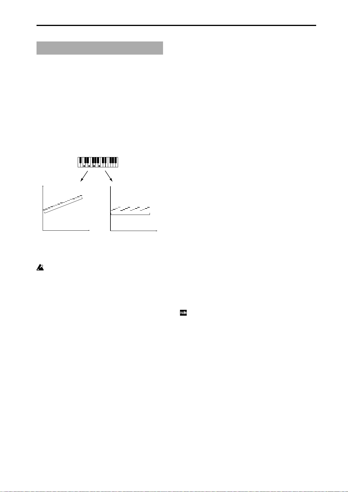
Gate Type [0…4]
0: [Vel]-retrigger notes with velocity
1: CC [T]-sustain notes; retrigger only if Phase
Transpose is different
2:
CC [1]-sustain notes; retrigger when entering Phase1
3:
CC [2]-sustain notes; retrigger when entering Phase2
4:
CC [A]-sustain notes; retrigger when entering any Phase
Available only when “GE Type” (☞p.4)= 1: Generated-Gated.
0: [Vel]-retrigger notes with velocity
The actual notes given as input source material are
generated repetitiously as note-ons and note-offs according to the parameters. This produces a “gated” effect
where each cluster of notes possesses the attack portion of
the program being used, as if someone was repeatedly
striking a keyboard very quickly.
CC - 4 different CC Gate Types
When one of the 4 “CC Gate Types” is chosen, “Gate CC
Number” becomes available. The actual notes given as
input source material are then generated as note-ons only
once at the beginning of the effect; the rest of the note-ons
are turned into the specified CC controller value with the
same value as the velocity of the note-on; the note-offs are
turned into CC values of 0. Essentially, this means that a
pad will be sustained, having the attack portion triggered
only once. For example, if the selected CC was #11
(Expression) or #07 (Volume), the pad will be repeatedly
turned on and off, simulating the popular techno effect of
gating a synth pad with a hi-hat track and an external
audio gate/compressor. In KARMA however, the Velocity
Pattern can be used to control the value of each CC that is
generated for a note-on (the volume of each “slice”), and
the Duration Pattern (☞p.17) can be used to control the
duration of each “slice.”
Other CCs can produce other interested stepped and
wave-sequence like effects. For example, using a CC to
control Filter Cutoff Frequency can produce interesting
“Sample & Hold” effects.
1: CC [T]-sustain notes; retrigger only if Phase Trans-
pose is different
When this first CC option is chosen, the “pad” will only
be triggered manually (i.e. when you strike the keyboard),
or only if there is a Phase Change and the Phase Transpose (☞p.10) is different, requiring that the generated
notes be transposed. Therefore, if the Phase Transposes
are the same, the “pad” will never retrigger unless you
trigger it manually.
4
Page 13
2:
CC [1]-sustain notes; retrigger when entering Phase1
Same as CC [T] above, with the exception that the “pad”
will be retriggered when striking the keyboard, and every
time that the Phase Pattern enters a step containing Phase
1. You can use this to have the notes retriggered occasionally while moving through the Phase Pattern.
3:
CC [2]-sustain notes; retrigger when entering Phase2
Same as CC [T] above, with the exception that the “pad”
will be retriggered when striking the keyboard, and every
time that the Phase Pattern enters a step containing Phase
2. You can use this to have the notes retriggered occasionally while moving through the Phase Pattern.
4:
CC [A]-sustain notes; retrigger when entering any Phase
Same as CC [T] above, with the exception that the “pad”
will be retriggered when striking the keyboard, and every
time that the Phase Pattern causes a Phase Change. You
can use this to have the notes retriggered occasionally
while moving through the Phase Pattern.
Gate CC Number [0…127]
Available only when “Gate Type” is one of the 4 CC
options. Chooses which CC will be transmitted
instead of the note-ons and note-offs of the generated
notes. For example, for “chopping” effects, set to 12
(CC#11).
0: Off
1…96: MIDI CC #00…95
97…127: N/A (Not available)
G E
5
Page 14
Note Series Group
Overview
The Note Series Group controls the creation of a “Note
Series” in memory , which is the foundation of nearly all
Generated Ef fects. The Note Series is a collection of
pitches and corresponding velocities, created from initial
notes coming from input source material (i.e. a keyboard).
The various parameters control how these initial notes are
replicated, shifted, sorted, filtered, and otherwise
arranged into the Note Series. The Note Series is then
used as the basic collection of pitches and velocities from
which notes are generated, as controlled by most of the
other parameters of the Generated Ef fect.
note
C9
C8
C7
C6
C5
C4
C3
C2
C1
C0
C-1
s
rie
S
te
o
N
note
C9
C8
C7
C6
C5
C4
C3
C2
C1
C0
C-1
step
Note Sries
2: Scalic 2
Same as 1: Scalic (above), except an attempt is made to
keep a seven note scale for each chord type. In other
words, there will be more passing tones, and it will sound
more “modal” in nature. For a good example of the
difference, play a 4 note diminished chord with each one.
This can be of use for creating a bass line that is more
predictable when changing chords, or jazzy soloing kinds
of ef fects.
3: Chromatic
The 12 steps of a chromatic scale will be used as input
source material. The first note of the Note Series is based
on the lowest note received as input source material.
4: WholeTone
The 6 steps of a whole tone scale will be used as input
source material. The first note of the Note Series is based
on the lowest note received as input source material.
5: Diminished
The 4 steps of a diminished chord will be used as input
source material. The first note of the Note Series is based
on the lowest note received as input source material.
6: Augmented
The 3 steps of an augmented chord will be used as input
source material. The first note of the Note Series is based
on the lowest note received as input source material.
7: Fourths
step
3 steps of stacked fourths will be used as input source
material. The first note of the Note Series is based on the
lowest note received as input source material.
Parameters
When “GE Type” (☞p.4) = 2: Generated-Drum, the
effect of changing most of these parameters is only
apparent if the Note Series is being applied as pitch
bend in the Phase Group/Bend Group, or riff length is
being used in the Drum Group.
Note Type [0…9]
0: Regular 4: WholeTone 8: Tritones
1: Scalic 5: Diminished 9: Fifths
2: Scalic2 6: Augmented
3: Chromatic 7: Fourths
Selects one of several modes for supplying the initial
notes from which the Note Series is created.
0: Regular
The Note Series created in memory will be produced based
on the actual notes given as input source material (i.e. a
keyboard).
1: Scalic
The Note Series created in memory will be produced
based on chord analysis of the input source material; then
a group of notes corresponding to the analyzed chord will
be used instead of the actual notes. The initial octave is
based on the lowest note received as input source
material. This can be used so that one finger chords
produce scalic rif fs, or to supply notes that are not present
in the source material.
8: Tritones
2 steps of a tritone (augmented fourth) will be used as
input source material. The first note of the Note Series is
based on the lowest note received as input source
material.
9: Fifths
2 steps (root and fifth) will be used as input source
material. The first note of the Note Series is based on the
lowest note received as input source material.
If “Root Position” is on (checked) in (☞ PG p.30), then
the pitches of the Note Series will be shifted so that
different inversions of the same chord produce the
same set of pitches.
Input Sort
0: Up 1: Down 2: Actual 3: Random
How the notes (and corresponding velocities) from the input
source material are arranged prior to creating the Note
Series.
0: Up
notes are arranged from lowest to highest.
1: Down
notes are arranged from highest to lowest.
2: Actual
notes are left in the order received.
3: Random
notes are randomly arranged.
6
Page 15

Inversion [–24…+24]
Allows dif ferent “inversions” of the notes prior to creation
of the Note Series. For example, if the notes {C, E, G, B}
were received in that order as a chord and Inversion was
1, then the notes would be shifted to {E, G, B, C 8va}
before creation of the Note Series (thus playing the 1st
inversion). This is especially useful for setting multiple
modules to play dif ferent inversions of the same ef fect,
such as natural harp glissandos or rif fs in harmony .
Normally used with Input Sort set to 0: Up or 1: Down.
The ef fect of this parameter when Input Sort is 2: Actual
or 3: Random is less predictable, although potentially
useful for some ef fects.
Replications [0…4000]
0…4000: range 0.0…40.0
How many times the input notes will be replicated
according to the Interval. For example, 3 “Replications”
with an “Interval” of 12 will give you a 3 octave arpeggio.
Can be a fraction to achieve only a portion of the last
replication. The value is represented as being x100 - so 350
is 3.5, 475 is 4.75, etc. Note that if “GE T ype” (☞p.4) = 1:
Generated-Gated, this has no audible ef fect on the pitches
of the Generated Ef fect; however this still af fects the
overall range of the available notes for Direct Indexing of
the Note Series (described elsewhere).
Interval [–24…+24]
The number of semitones to offset each replication of the
input notes by. For example, if set to +12 or -12, the Arpeggio
will repeat in octaves (most normal). If set to 2, and “Replications” to 3, then playing a CMaj {C, E, G} will produced a
CMaj, then DMaj {D, F#, A}, then EMaj {E, G#, B} as each
replication is shifted by a whole-tone. Settings other than
multiples of 12 are extremely useful in conjunction with
“Chord Shift,” described below, so that atonal notes are
shifted to musically correct pitches.
Chord Shift [0…2]
0: Off 1: Scalic 2: Scalic2
0: Off
The Note Series is created with no further modification
from this setting.
1: Scalic
Chord analysis is performed on the input source material,
and as the Note Series is created, notes which may be
“atonal” based on the analyzed chord (due to being
shifted by non-octave values of “Interval”) are shifted to
tonal notes. Especially useful when “Interval” (discussed
above) is set to something other than multiples of 12. The
note tables used to shift the notes are the same as the ones
used in “Note Type” (☞p.6) : 1: Scalic, described above.
Note Series
Max [1…255]
Sets an overall “final place” in the Note Series, beyond which
indexes will never be chosen during playback, even if other
settings might allow it. This is a playback only parameter
which does not affect the creation of the Note Series.
Symmetry [0, 1]
0: Off 1: On
When turned 1: On, additional notes are extrapolated at
the end of the Note Series beyond the number specified by
the “Replications” setting, which are accessed when
clusters are generated in that area of the Note Series, or
when the Index Group “Double/Invert” parameters
(☞p.20, 21) are used. This primarily allows dif ferent
cluster sizes to be used without af fecting the length and
shape of the resulting rif f. This interacts with Cluster
Patterns and the Index Pattern Cluster Advance Mode,
discussed elsewhere. Note that when this is 0: Off,
clusters will “wrap around” at the end of a phase, or
cause Phase Changes or cycling. Doubled notes caused by
the use of the “Double” parameter in the Index Group will
also be wrapped around at the top of the Note Series
when this is of f.
0: Off
The notes determined by the Repetitions setting (described above) are used as the range within which to
generate notes.
1: On
Extra notes may be extrapolated at the end of the range
depending on the cluster size at that point. The result will
be a widening of the apparent range of the rif f.
2: Scalic2
Same as 1: Scalic (above), except that the note tables used
to shift the notes are the same as the ones used in “Note
Type”: 2: Scalic2, described above. Scalic2 is more modal
in nature and has more passing tones than 1: Scalic.
Wrap Bottom [0…127] Wrap Top [0…127]
0…127: range C-1…G9
Sets an overall range for the pitches in the Note Series.
Notes created beyond this range are wrapped around
(dropped or raised an octave, depending on which end).
Mainly intended to limit the Note Series to useable
ranges, these settings can also be used creatively to force a
riff to cycle around inside a certain range.
Voicing [0…8]
0: Closed 3: Open2A 6: Open3B
1: Open1A 4: Open2B 7: Open4A
2: Open1B 5: Open3A 8: Open4B
0: Closed
The Note Series is created with no further modification
from this setting.
1…8: Open 1A…4B
The Note Series has certain notes shifted up by an octave
as it is created, then may be re-ordered according to the
setting of the “Input Sort” ( ☞p.6) . Can be used to create
different types of wider voiced chords for simulating
guitar or string section voicings.
7
Page 16
Filter Dupes [0…2]
0: Of 1: Adjacent 2: All
0: Off
The Note Series is created with no further modification
from this setting.
1: Adjacent
As the Note Series is being created, notes which are the
same as the immediately preceding note are discarded.
2: All
After the Note Series has been created, any notes which
are duplicates of any others are removed.
Not available if “GE T ype” (☞p.4) = 1: Generated-
Gated.
Filter Fixed [0, 1]
0: Off 1: On
When Filter Steps is used (described below),
allows the resulting tonality of the Note Series to be
“Filter Fixed” in relation to the key of C. For example,
assume that “Note Type” (☞p.6) is set to Chromatic and
“Chord Shift” is Off, so that the Note Series is essentially
a chromatic scale. If you play a single C (and “Inversion”
(☞p.7) is set to 0), you will get a chromatic scale starting
with C. If you then set up Filter Steps so that you are
filtering steps {1, 3, 6, 8, 10} you would have a C Major
diatonic scale. With “Filter Fixed” set to Off, if you then
play a D on the keyboard, the whole scale will shift to
become a D Major diatonic scale. With “Filter Fixed” set
to On, the scale stays fixed to the key of C, but you are
starting on the D; essentially , you have a D minor scale.
You will be playing dif ferent modal scales starting with
different pitches. Note that this is always related to the
key of C; so if you want to put the resulting filtered, fixed
Note Series into another key , you can use the Transpose
(6.2–1a) KARMA Module parameter to do so. For
example, if you set the transpose to +4, you would still
play notes in the key of C, but the resulting generated
notes would be in the key of E. In the above example,
playing a C would result in a E diatonic scale, playing a D
results in an F# minor scale (F# Dorian mode) and so on.
if {C, E, G, B} was the input material, CMaj7 would be
the analyzed chord; if step #4 “3rd” was selected on the
grid, all occurrences of E would be removed from the
Note Series. Useful for creating complex grooves where
several modules are all supplied with the same source
material, where for example you might not want the bass
line to play the 3rd even if it is supplied from the
keyboard, might want to remove all chance of 7ths from
a comping guitar part, etc.
Selecting all steps to be filtered will result in a single
note in the Note Series, determined by the settings
of other parameters such as “Input Sort”, “Inver sion”, etc.
To “fix” the resulting filtered collection of notes with
regards to a specific key , use “Filter Fixed” (described above).
Not available if “GE T ype” (☞p.4) = 1: Generated-
Gated.
The following 3 parameters will have an ef fect on
when Phases change if the Phase “Length Mode”
(☞p.9) is set to 0: AC-Actual: “Replications” ( ☞ p.7) ,
“Filter Steps” (Filter T emplate), and “Filter Dupes”.
See Phase Group.
Not available if “GE T ype”(☞p.4) = 1: Generated-
Gated.
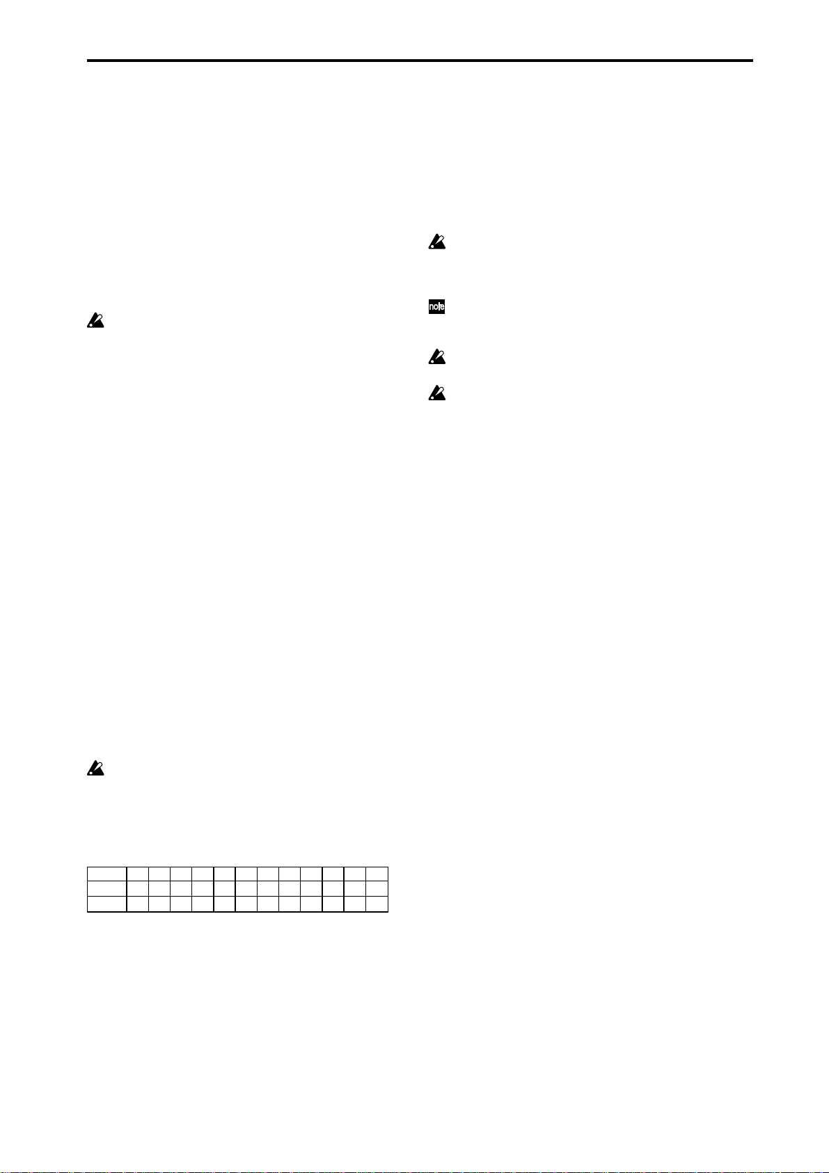
Filter Template [0…77]
Selects from 78 dif ferent combinations of preset “Filter
Steps” settings.
Step #1 #2 #3 #4 #5 #6 #7 #8 #9 #10 #11 #12
Key: C C C# D D# E F F# G G# A A# B
Key: E E F F# G G# A A# B C C# D D#
[Filter Steps]
A 12 step grid corresponds to the scale tones with regard
to a current “key,” which is determined by Chord Analysis
of the input source material. For example, if the key is
determined to be C, then the steps 1 through 12 correspond to C, C#, D to B; if the key is determined to be “ E,”
then steps 1 through 12 correspond to E, F, F# to D#. After
the Note Series is created, notes belonging to the chosen
steps are removed, thus “filtering” them out. For example,
8
Page 17
Phase Group
Overview
A Generated Effect has two different “Phases.” Each of
them is a separate collection of certain parameters
including Rhythm, Velocity, Cluster, Pan and Index
Patterns, among others. As the effect is generated, a Phase
Pattern controls switching between the two Phases, so that
completely different collections of parameters can be used
for a period of time. The Phase Group contains parameters
which control the length, direction, and various other
attributes of each Phase, the number of times and in what
order the Phases will play, and whether or not a portion
will be looped.
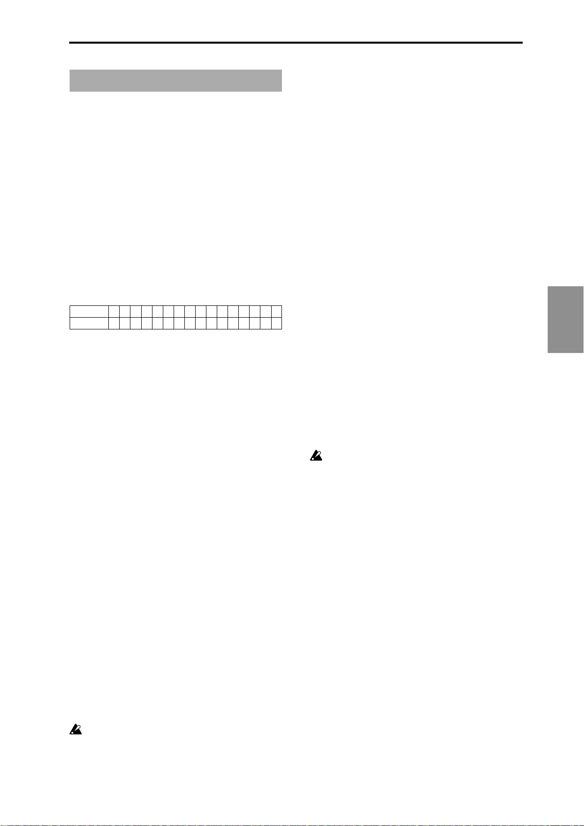
About Phase Patterns
Phase Pattern = 8
Step
Phase1/2 1 1 1 1 1 1 1 2
The Phase Pattern allows a pattern of switching between
the 2 Phases of a Generated Effect to be constructed. The
resulting Phase Pattern may have a minimum of 1 step
and a maximum of 16 steps. The example above shows an
8 step Phase Pattern: 7 times through Phase 1 followed by
once through Phase 2. After completing the 8 steps,
execution may loop back to Step 1. Note that the actual
number of steps performed and whether it loops back at
the end will be determined by other settings described in
this chapter.
General Parameters
This group of parameters affects some overall characteristics of Phase performance.
1 2 3 4 5 6 7 8 9 10111213141516
Start Mode [0…3]
0: T-only when Triggered
1: 1-when entering Phase1
2: 2-when entering Phase2
3: A-when entering any Phase
Controls how the “Start %” described above is applied to the effect as it is being generated.
0: T-only when Triggered
The “Start %” is applied only when the effect is triggered,
i.e. from the keyboard or through Dynamic MIDI. When
other steps of the Phase Pattern are entered during
subsequent playback, the Note Series will reset to either
the top or bottom depending on the Phase “Direction”
setting and Phase “Beginning/End Offset” settings.
1: 1-when entering Phase1
Each time that playback of a Phase Pattern step containing
Phase 1 begins, the “Start %” will be applied. This can be
used to start a phase somewhere in the middle of the Note
Series from which the indexes can be chosen in either
direction according to the Index Pattern.
2: 2-when entering Phase2
Each time that playback of a Phase Pattern step containing
Phase 2 begins, the “Start %” will be applied. This can be
used to start a phase somewhere in the middle of the Note
Series from which the indexes can be chosen in either
direction according to the Index Pattern.
3: A-when entering any Phase
Each time that playback of any Phase Pattern step begins,
either Phase 1 or Phase 2, the “Start %” will be applied.
This can be used to start a phase somewhere in the middle
of the Note Series from which the indexes can be chosen
in either direction according to the Index Pattern.
Not available when “GE Type” (☞p.4) = 1: Gener-
ated-Gated . If 2: Generated-Drum , the Note Series
can be applied as pitch bend, discussed elsewhere.
Length Mode [0…2]
Phase
Total Steps [0…32]
0: (infinity) 1...32: number of steps
Sets the total number of steps of the Phase Pattern that will
be played before stopping. The infinity sign 0: (infinity) sets
it to loop forever; otherwise the setting represents a number
of steps of the selected Phase Pattern. For example, if the
Phase Pattern is a simple 2-step pattern of {1, 2}, and the Total
Steps menu is {4}, then 4 Phases would be played in the
following order before stopping: {1, 2, 1, 2}.
Start % [0…100 (%)]
Controls the location in the Note Series at which the effect
will start when it is triggered. Closer to 0% starts nearer
the beginning while closer to 100% starts nearer the end;
beginning/end relates to highest/lowest depending on
the Phase “Direction” (☞p.10) setting. This can be applied
just once when first triggering the effect, or as various
steps of the Phase Pattern are entered, in conjunction with
the Start Mode described below.
Not availabF when “GE Type” (☞p.4) = 1: Gener-
ated-Gated . If 2: Generated-Drum , the Note Series
can be applied as pitch bend, discussed elsewhere.
0: AC-Actual 1: TS-Time Signature 2: EV-Events
Determines when a Phase Change from the current step to
the next step of the Phase Pattern will occur. Note that this
has a certain interaction with the Cycle Mode parameter,
described below.
0: AC-Actual
Causes the Phase Change to be completely dependent on
the length of the Note Series and the Phase “Beginning/
End Offsets.” The portion of the Note Series to be used as
specified by the Phase “Beginning/End Offsets” (described below) is referred to as the “playback portion” of
the Note Series. The notes are generated by moving
through the Note series according to the Index Group
settings; when either end of the playback portion has been
reached, a Phase Change occurs (depending on the setting
of the “Cycle Mode” parameter (☞p.10) , described
below). Therefore, if more or less notes are played, the
Phases will change sooner or later and bear no relation to
any time signatures or specific number of events.
This is useful for GEs that model the behavior of most
simple arpeggiators.
9
Page 18
Not available if “GE Type ” ( ☞p.4) = 1: Generated-
Gated .
1: TS-Time Signature
Makes the Time Signature parameters (“Tsig Numerator/
Denominator” ☞p.11) available in the Phase Specific
Parameter area of each Phase (described below). These
allow setting each Phase to various time signatures, which
cause the Phase to playback a certain number of beats
regardless of any other circumstances which might trigger a
Phase Change. When moving through the Note Series, if
either end of the playback portion is reached (specified by
the “Phase Beginning/End Of fsets” ☞p .11) before the
amount of beats specified has occurred, then the movement
either freezes and repeats at that point, or cycles back and
continues (depending on the setting of the “Cycle
Mode”parameter, described below). Useful for groove
generation and constraining ef fects to certain time signatures.
2: EV-Events
Makes the "Events" parameter available in the Phase
Specific Parameter area of each Phase (described below).
This is used to set the Phase to perform a certain number
of events before changing Phases (an event being a note or
cluster). When moving through the Note Series, if either
end of the playback portion is reached (specified by the
“Phase Beginning/End Offsets” ☞p.11) before the number
of events specified has occurred, then the movement
either freezes and repeats at that point, or cycles back and
continues (depending on the setting of the “Cycle Mode”
parameter, described below). Useful for constraining
effects to a certain number of specific events, such as 4
strums per Phase.
Cycle Mode [0…3]
0: OFF
1: B-Beginning Of Phase
2: E-End Of Phase
3: BE-Beginning & End Of Phase
Determines what will happen when either end of the
playback portion of the Phase (specified by the “Phase
Beginning/End Offsets”) is reached during note generation.
This has a dif ferent ef fect depending on the setting of the
Phase “Length Mode” (above). If 1: TS-Time Signature or 2:
EV-Events Mode, “cycling” can be allowed to occur; if 0: AC-
Actual, an immediate Phase Change will occur .
Not available if “GE Type” ( ☞p.4) = 1: Generated-
Gated . If 2: Generated-Drum , the Note Series can be
applied as pitch bend, discussed elsewhere.
0: OFF
If the Phase “Length Mode” is 1: TS-Time Signature or 2:
EV-Events, when either end of the playback portion of the
Phase is reached, the movement freezes and repeats at
that point until the specified number of events or beats of
a time signature are generated; then a Phase Change
occurs. Settings of the Index Pattern which would cause
movement beyond that point have no effect. If the Phase
“Length Mode” is 0: AC-Actual, then when the end of the
playback portion is reached no Phase Change occurs. Note
that this means the Phase will never change, and has
mainly been allowed only for completeness with the more
normal uses below.
1: B-Beginning Of Phase
If the Phase Length Mode is 1: TS-Time Signature or 2: EVEvents, allows “cycling” to occur at the beginning of the
playback portion of the Phase. For example, if the movement
specified by the Index Pattern causes the index to go
backwards beyond the beginning of the playback portion,
“cycling” will occur (the index will automatically be jumped
back into the playback portion by a calculated amount). If
the Phase “Length Mode” is 0: AC-Actual, then if the
movement specified by the Index Pattern causes the index to
go backwards beyond the beginning of the playback portion,
a Phase Change will immediately occur .
2: E-End Of Phase
If the Phase “Length Mode” is 1: TS-Time Signature or 2:
EV-Events, allows “cycling” to occur at the end of the
playback portion of the Phase. For example, if the movement
specified by the Index Pattern causes the index to go
forwards beyond end of the playback portion, “cycling” will
occur (the index will automatically be jumped back into the
playback portion by a calculated amount). If the Phase
“Length Mode” is 0: AC-Actual, then if the movement
specified by the Index Pattern causes the index to go
forwards beyond the end of the playback portion, a Phase
Change will immediately occur . This is probably the most
“normal” and easily understood setting.
3: BE-Beginning & End Of Phase
Allows the behaviour described above at both ends of the
playback portion of the Phase.
Phase Specific Parameters
For each of the 2 Phases, a group of Phase Specific
Parameters allow control of some performance characteristics within each Phase. If settings of the Phase Pattern
indicate a particular Phase is not being used, the Phase
Specific Parameters for that Phase will not be available.
Direction [0, 1]
0: Forward 1: Backward
Selects the direction for general movement through the
Note Series in a particular phase. Works in conjunction
with the parameters in the Index Group, which control
how the index(es) move through the Note Series. For
example, when the Direction is 0: Forward , the Index
Pattern values are added to the index to move it through
the Note Series from left to right; when Direction is 1:
Backward , the Index Pattern values are subtracted to
move the index through the Note Series from right to left.
Not available when “GE Type” (☞p.4) = 1: Gener-
ated-Gated . If 2: Generated-Drum , the Note Series
can be applied as pitch bend, discussed elsewhere.
Transpose [–36…+36 (semitones)]
Allows each Phase to be transposed individually. Has no
effect on Direct Indexing effects, which have a separate
Transpose parameter (see Direct Index Group).
Not available when “GE Type”(☞p.4) = 2: Generated-
Drum .
10
Page 19
Octave Transpose [–36…+36]
Allows the Phase’s Transpose value to be quantized to the
nearest octave, so that when being changed in real-time,
only transposition by octaves is possible. In this case, the
value of the parameter changes by semitones, but the
actual transpose value will only change at certain points
within the range:
-36 to -31 = -36 (-3 octaves)
-30 to -19 = -24 (-2 octaves)
-18 to -7 = -12 (-1 octave)
-6 to +5 = 0 (no transpose)
+6 to +17 = +12 (+1 octave)
+18 to +29 = +24 (+2 octaves)
+30 to +36 = +36 (+3 octaves)
Oct/5th Transpose [–36…+36]
Allows the Phase’s Transpose value to be quantized to the
nearest octave or fifth, so that when being changed in realtime, only transposition by octaves or fifths is possible. In
this case, the value of the parameter changes by
semitones, but the actual transpose value will only change
at certain points within the range:
-36 to -33 = -36 (-3 octaves)
-32 to -27 = -29 (-3 octaves +5th)
-26 to -21 = -24 (-2 octaves)
-20 to -15 = -17 (-2 octaves +5th)
-14 to -9 = -12 (-1 octave)
-8 to -3 = -5 (-1 octave +5th)
-2 to +3 = 0 (no transpose)
+4 to +9 = +7 (+5th)
+10 to +15 = +12 (+1 octave)
+16 to +21 = +19 (+1 octave +5th)
+22 to +27 = +24 (+2 octaves)
+28 to +33 = +31 (+2 octaves +5th)
+34 to +36 = +36 (+3 octaves)
Events [1…96]
TSig Numerator [0…31]
0…31: 1…32
TSig Denominator [0…4]
0: 16 1: 12 2: 8 3: 6 4: 4
The availability of these parameters vary according to the
setting of the Phase “Length Mode” (☞p.9), described in
General Parameters above. When the Phase “Length
Mode” is 1: TS-Time Signature, “TSig Numarator” and
“TSig Denominator” are available which allow you to
specify various time signatures for each Phase. A certain
number of beats is then performed in the Phase, regardless of any other circumstances which might trigger a
Phase Change. When the Phase “Length Mode” is 2: EV-
Events, a events is available which allows you to specify a
certain number of events (an event being a note or cluster
of notes). The specified number of events is then performed in each Phase, regardless of any other circumstances which might trigger a Phase Change. When the
Phase “Length Mode” is 0: AC-Actual , then these
parameters are not available. The Phases will then change
according to the movement through the Note Series.
0: AC-Actual not available when GE Type (☞p.4) = 1:
Generated-Gated .
Beginning Offset % [0…100 (%)] End Offset % [0…100 (%)]
Sets an overall beginning and end range in the Note Series
for note generation within the Phase. Even though
settings in the Note Series Group may have created a very
long Note Series, these can be used to select just a portion
of the Note Series from which to generate notes over the
length of a particular Phase.
For example, if the “Beginning Offset” is 25% and the
“End Offset” is 75% , note generation within the Phase
would be restricted to coming from the portion of the
Note Series 1/4 to 3/4 of the way from the beginning.
Not available when “GE Type” (☞p.4) = 1: Gener-
ated-Gated . If 2: Generated-Drum , the Note Series
can be applied as pitch bend, discussed elsewhere.
End Loop Parameters
Determines whether a portion of the effect will loop, after
a certain number of steps of the Phase Pattern have been
completed. Note that once the loop has started, it
continues using the Phase Pattern, and current Phase
“Length Mode”.
End Loop On/Off [0, 1]
0: Off 1: On
Enables/disables this feature, and the following two
parameters.
End Loop Start Step [1…17]
Chooses a step of the Phase Pattern after which looping
begins. For example, if the Phase Pattern was set to a 2
step pattern of {1, 2} and the Start Step menu to 4 , the loop
would be entered after the 2nd time through the Phase
Pattern, at the end of the 4th step in total. Not available if
the “End Loop On/Off” is set to 0: Off .
End Loop Length [1…96]
1…96: events
Determines how many events (notes or clusters) will be
moved forward/backward while looping, according to
various other parameters such as the Index Pattern. Not
available if the “End Loop On/Off” is set to 0: Off .
Phase
11
Page 20

Pattern Parameters
Pattern Items [1…16 (steps)]
Sets the number of steps in the Phase Pattern.
Pattern Step1…16 [0, 1]
0: Phase1 1: Phase2
Sets which phase (Phase 1 or Phase 2) will be used for
generating data when a specific step of the Phase Pattern
is entered during playback. For each step that is enabled,
the step may be set to either Phase 1 or Phase 2.
Note that if the number of steps in the Phase Pattern
(Pattern Items) is less than the step being edited, this will
produce no audible results.
Template Parameters [0…15]
The following 5 parameters select 1 of 16 templates (each
having 4 steps) that can be applied to all or parts of the
Phase Pattern. They specify 16 different combinations of
Phase 1 and Phase 2 within a 4 step section:
0: 1-1-1-1 6: 1-2-1-1 12: 1-2-2-2
1: 2-2-2-2 7: 2-1-1-1 13: 2-2-2-1
2: 1-2-1-2 8: 1-1-2-2 14: 2-2-1-2
3: 2-1-2-1 9: 1-2-2-1 15: 2-1-2-2
4: 1-1-1-2 10: 2-2-1-1
5: 1-1-2-1 11: 2-1-1-2
Template (All Steps)
The chosen template is applied to all steps of the Phase
Pattern, regardless of how many there are. For example, if
you selected 6: 1-2-1-1 (Template 6), then the following
would happen to the Phase Pattern:
If the Phase Pattern had 1 step: 1
If the Phase Pattern had 2 steps:
If the Phase Pattern had 4 steps:
If the Phase Pattern had 7 steps:
If the Phase Pattern had 16 steps:
1-2
1-2-1-1
1-2-1-1 1-2-1
1-2-1-1 1-2-1-1 1-2-1-1 1-2-1-1
Template Steps 1…4
Applies the selected template only to the first 4 steps of
the Phase Pattern.
If there are more steps, they will remain unchanged.
Template Steps 5…8
Applies the selected template only to steps 5-8 of the
Phase Pattern. If there are more steps, they will remain
unchanged. Steps 1–4 will remain unchanged.
Template Steps 9…12
Same as above, except for steps 9–12.
Template Steps 13…16
Same as above, except for steps 13–16.
Note that if the number of steps in the Phase Pattern
(Pattern Items) is less than the steps for which Templates
are being changed, these will produce no audible results.
12
Page 21

Rhythm Group
Overview
The Rhythm Group controls the rhythmic characteristics
of the Generated Ef fect. It can also have an influence on
when “Auto Bend” pitch bending ef fects (set up on the
Bend Group) are generated.
About Rhythm Patterns
Rhythm Patterns control how often and when exactly
notes will be generated. A value derived from a Rhythm
Pattern is the size of the step between each generated
note. Choices can be made from “Random Pools” ( ☞p.14)
of values as described in detail later on. Furthermore,
values can be tied to each other; the ties can be absolute or
random.
Rhythm Patterns may be multiplied by the “Rhythm
Multiplier ,” which gives them many more variations, in
addition to providing easy ways to experiment with
fractal and poly-rhythmic ef fects. A Rhythm Pattern of
{8th, 16th, 16th} with a “Rhythm Multiplier” ( ☞p.15) of
200% will play {Quarter, 8th, 8th}.
A Rhythm Pattern will loop as long as note generation
continues. It normally will not reset to the beginning of
the Pattern unless a new T rigger is received, or the Phase
Pattern has been configured to restart it at the beginning
of certain Phases. That means that a 4 step Rhythm
Pattern can be looping while an 8 step V elocity Pattern
and a 12 step Cluster Pattern are also independently
looping, for example.
Global Parameters
Humanize [0…255 (ms)]
Sets a range in milliseconds within which each note/
cluster may be randomly shifted in time. For example, if
set to 10 ms, then each cluster or note as it is generated
has a possibility of a random of fset in time of between 0 to
10 ms. This af fects all of the notes in the cluster at the
same time. This can be used to impart a more “human,”
less machine-like precision to generated notes. This can
also be used to totally destroy the timing!
Swing % [0…100 (%)]
Percentage of swing/hip-hop feeling to be applied. 0% =
no swing, 50% = triplets, while 100% pushes the swung
notes all the way to the next value of half the note length
set by the “Swing Note V alue”. For example, if swinging
straight 1: 16th notes, 100% would push the swung notes
to 32nds. Note that triplet rhythm values are not af fected
by swing.
Swing Use Multiplier [0…3]
0: Off 2: P1-Phase1
1: Ind-Independently 3: P2-Phase2
The “Rhythm Multiplier” (explained later on in this
chapter) causes the values in the Rhythm Pattern to be
increased or decreased by a percentage. The “Swing Use
Multiplier” specifies several options for selectively
applying (or not applying) the Rhythm Multiplier(s) to the
“Swing Note V alue” also, thereby af fecting the resulting
swing feel.
0: Off-do not use Multipliers for Swing
The “Rhythm Multipliers” in each Phase do not have any
affect on the “Swing Note Value”. For example, if generating
16th notes with a “Rhythm Multiplier” of 100% and “Swing
Note Value” set to 1: 16th note, the resulting 16th notes will
be swung with a 16th note feel. If the “Rhythm Multiplier” is
changed to 50%, the resulting 32nd notes will still be swung
with a 16th note feel. If the “Rhythm Multiplier” is changed
to 200%, the resulting 8th notes will also be swung with a
16th note feel, resulting in no perceptible swing (unless the
rhythm is syncopated).
1: Ind-independently use each Phase’s Multiplier
Each Phase’s “Rhythm Multiplier” ( ☞p.15) will independently af fect swing calculations while generating rhythms
within that Phase. In other words, the “Swing Note V alue”
will also have the “Rhythm Multiplier” applied to it. For
example, if generating 16th notes with a “Rhythm
Multiplier” of 100% and “Swing Note V alue” set to 1: 16th
note, the resulting 16th notes will be swung with a 16th
note feel. If the “Rhythm Multiplier” is changed to 50%,
the resulting 32nd notes will be swung with a 32nd note
feel. If the “Rhythm Multiplier” is changed to 200%, the
resulting 8th notes will be swung with an 8th note feel.
With this setting, it is possible to swing with dif ferent note
values in the two Phases, such as swinging with an 8th
note feel in one phase and swinging with a 16th note feel
in the other .
Rhythm
Swing Note Value [0…3]
0: 32th note 2: 8th note
1: 16th note 3: 4th note
The base note value to be used in calculating swing. For
example, if you want to add a swing feel to a steady string
of 16th notes, you would select a 1: 16th note. Straight 8th
notes would exhibit no change with this setting, since they
do not swing in such a feel unless they are syncopated. On
the other hand, if you swing 16th notes with a 2: 8th note
Swing Note selected, the 16th notes are swung in an 8th
note feel. While this is not necessarily natural “swing,”
interesting shiftings of timings can be produced. Note that
the setting of this parameter can be modified by the
“Swing Use Multiplier” parameter , explained below .
2: P1-always use Phase1’s Multiplier
Same as 1: Ind above, except that Phase 1’s “Rhythm
Multiplier” will always be used, regardless of which
Phase is currently generating rhythms. This allows the
Rhythm Multiplier to be varied in Phase 1 while af fecting
the overall swing settings for the whole ef fect. For
example, if generating 16th notes in both phases with both
Phase’s “Rhythm Multipliers” set to 100% and “Swing
Note Value” set to 1: 16th note, the resulting 16th notes
will be swung with a 16th note feel. If Phase 1’s “Rhythm
Multiplier” is changed to 200%, the resulting 8th notes in
Phase 1 and 16th notes in Phase 2 will all be swung with
an 8th note feel. If the “Rhythm Multiplier” in Phase 1 is
100% and changed to 50% in Phase 2, the resulting 16th
notes in Phase 1 and 32nd notes in Phase 2 will all be
swung with a 16th note feel.
13
Page 22

3: P2-always use Phase2’s Multiplier
Same as 2: P1 described above, except utilizing Phase 2’s
“Rhythm Multiplier .”
Pattern Grid & Associated Parameters
Rhythm Pattern
A Rhythm Pattern controls the rhythm that the notes are
generated with according to a grid of rhythmic values. It
has any number of steps up to 32, with each step being
represented by one column on the grid. The first column
always contains at least one value; unused columns
appear disabled. The top part of the grid corresponds to
18 different rhythmic values; the bottom 3 rows are special
purpose rows:
[ties: rand] - Random Tie: randomly ties the rhythmic
value in the same column to the previous column’ s
rhythmic value. For example, a 16th note in the first
column followed by a 16th note and a random tie in the
2nd column yields either an 8th note or two 16th notes.
When at least one random tie has been selected, a
weighting curve is available which allows choices to be
slanted towards more ties or less ties, as described later .
[ties: abs] - Absolute T ie: always ties the rhythmic value in
same column to the previous column’ s rhythmic value.
For example, a 16th note in the first column followed by a
16th note and an absolute tie in the 2nd column yields an
8th note.
The 2 tie rows are mutually exclusive; only one at a time
can be used in any given column.
[no bend] - No Bend: af fects when Automatic Pitch
Bending ef fects can occur , as set up in the Bend Group.
These ef fects will normally be triggered with every single
generated note or cluster; by using the “no bend” row ,
bends can be prevented from occurring on various steps
of the Rhythm Pattern.
Pattern grids cannot viewed and edited in the
KARMA Music Workstation.
Random Weighting Parameters - Pools
The Random W eighting Parameters - Pools are made
available when at least one step (column) in the Rhythm
Pattern has multiple rhythmic values selected (constituting a “random pool” of values).
Whenever a random pool is encountered in playing
through the pattern, a random choice is made from the
rhythmic values in that step. Certain areas of the random
pool can be favored by the use of a weighting table, with
various shaped curves. Using the curves, you can
influence certain choices to be made more or less often
than others, allowing very musical real-time control of the
randomness.
Whether or not a certain random sequence will repeat for
a number of times is controlled by settings in the Phase
Pattern.
Pools-Random Factor [–99…+99]
Controls the degree of slope to the W eighting Curve. 0 = a
Linear Curve with any Weighting Curve. Negative values
not only invert but rotate the curve. When the value is
either +99 or -99, the choices are “locked” to the highest or
lowest values in the columns, and there are no random
choices at all. (The only exception to this is an S-shaped
curve with a value of -99. In this case, a random choice
will be made between the highest and lowest values only .)
For more information, see the Appendices: “Random
Weighting Curves.” ( ☞p.50)
Pools-WeightingCurve (Pools-Weighting Curve)
[0…3]
0: Exponential 2: Exp-S
1: Logarithmic 3: Log-S
4 different shapes are available, which act to favor certain
areas of the pool over others when each random choice is
made. For more information, see the “Appendices
Random Weighting Curves.” ( ☞p.50)
0: Exponential
With a positive Factor (+), choices will be exponentially
weighted towards the shorter rhythms. W ith a negative
Factor (-), choices will be exponentially weighted towards
the longer rhythms.
1: Logarithmic
With a positive Factor (+), choices will be logarithmically
weighted towards the shorter rhythms . W ith a negative
Factor (-), choices will be logarithmically weighted
towards the longer rhythms.
14
2: Exp-S (Exponential S)
With a positive Factor (+), choices will be exponentially
weighted towards the middle rhythms , and away from
the shorter and longer rhythms. W ith a negative Factor (-),
choices will be exponentially weighted towards the
shorter and longer rhythms , and away from the middle
rhythms.
Page 23

3: Log-S (Logarithmic S)
With a positive Factor (+), choices will be logarithmically
weighted towards the middle rhythms , and away from
the shorter and longer rhythms. W ith a negative Factor (-),
choices will be logarithmically weighted towards the
shorter and longer rhythms, and away from the middle
rhythms.
A Factor of 0 with any shaped curve yields a linear
table (straight diagonal line), and each of the values
in the pool will have an equal chance of getting
chosen.
While exponential and logarithmic curves may seem
to have a similar shape, they have slight dif ferences
which can af fect the outcome of the random choices.
For more information, see the Appendices: “Random
Weighting Curves.” ( ☞p.50)
The following table summarizes the ef fect of the various
Weighting Curves and the Factor field on the choices from
the Rhythm Pools:
Rhythm Pool values that receive priority:
Weighting Factor
Curve + (Positive) - (Negative)
Exp/Log longer shorter
Exp-S/Log-S middle shorter/longer
0: Exponential
With a positive Factor (+), choices will be exponentially
weighted towards rhythm values more often. W ith a
negative Factor (-), choices will be exponentially weighted
towards ties more often.
1: Logarithmic
With a positive Factor (+), choices will be logarithmically
weighted towards the rhythm values more often. W ith a
negative Factor (-), choices will be logarithmically
weighted towards the ties more often.
While exponential and logarithmic curves may seem
to have a similar shape, they have slight dif ferences
which can af fect the outcome of the random choices.
For more information, see the Appendices: “Random
Weighting Curves.” ( ☞p.50)
A Factor of 0 with any shaped curve yields a linear
table (straight diagonal line), and a random tie or a
rhythm value in the pool will have an equal chance of
getting chosen.
The following table summarizes the ef fect of the various
Weighting Curves and the Factor field on random ties:
Values that receive priority:
Weighting Factor
Curve + (Positive) - (Negative)
Exp/Log less ties more ties
Random Weighting Parameters - Ties
The Random W eighting Parameters - T ies are made
available when at least one step in the Rhythm Pattern
contains a Random T ie. Whenever this step is encountered
in playing through the pattern and a random choice must
be made, the likelihood of a tie occurring can be favored
by the use of a weighting table.
Ties-Random Factor [–99…+99]
Controls the degree of slope to the W eighting Curve. 0 = a
Linear Curve with any W eighting Curve. Negative values
not only invert but rotate the curve. When the value is
+99, the choices are “locked” to no ties whatsoever; when
the value is -99, the choices are “locked” to ties always
(and the ef fect is the same as if absolute ties were
selected). For more information, see the Appendices:
“Random Weighting Curves.” ( ☞p.50)
Ties-Weighting Curve [0, 1]
0: Exponential 1: Logarithmic
2 different shapes are available, which affect the likelihood of
a tie occurring when a random choice is made. For more
information, see the Appendices: “Random Weighting
Curves.” (☞p.50)
Associated Parameters
Rhythm Multiplier [1…800 (%)]
Multiplies the selected Rhythm Pattern by the percentage.
Useful for poly-rhythmic and fractal effects, such as using
the same Rhythm Pattern at different multiplications. For
example, if a Pattern is {16th, 8th, 8th}, then using a “Rhythm
Multiplier” of 50% changes it to {32nd, 16th, 16th}; using a
“Multiplier” of 200% changes it to {8th, Quarter, Quarter}.
Straight Multipliers [0…5]
0: 25% 2: 100% 4: 400%
1: 50% 3: 200% 5: 800%
Selects from a quantized set of “straight” values for the
Rhythm Multiplier field. In other words, when applied to
a Rhythm Pattern containing values such as 16th notes,
the resulting rhythmic values will be straight values such
as 8th notes, quarter notes, etc.
Straight/Trip Mults [0…10]
0: 25% 4: 100% 8: 400%
1: 34% 5: 136% 9: 544%
2: 50% 6: 200% 10: 800%
3: 68% 7: 272%
Selects from a quantized set of “straight & triplet” values
for the Rhythm Multiplier field. In other words, when
applied to a Rhythm Pattern containing values such as
16th notes, the resulting rhythmic values will be straight
values such as 8th notes, quarter notes, etc. or various
triplet values.
Rhythm
15
Page 24

Strt/Dot/Trip Mults [0…15]
0: 25% 4: 68% 8: 150% 12: 400%
1: 34% 5: 75% 9: 200% 13: 544%
2: 37% 6: 100% 10: 272% 14: 600%
3: 50% 7: 136% 11: 300% 15: 800%
Selects from a quantized set of “straight, triplet & dotted”
values for the Rhythm Multiplier field. In other words,
when applied to a Rhythm Pattern containing values such
as 16th notes, the resulting rhythmic values will be
straight values such as 8th notes, quarter notes, etc.,
various triplet values, or various dotted values.
Template [0…63]
Selects from 64 dif ferent Rhythm Pattern T emplates
(shared by both Phase 1 and 2), and loads the parameters
into the current Phase’ s Pattern Grid and associated
parameters.
A Rhythm Pattern T emplate consists of:
• the configuration of the Rhythm Pattern Grid;
• Random Weighting Parameters - Pools
• Random Weighting Parameters - T ies
16
Page 25

Duration Group
Overview
The Duration Group contains the parameters that control
the duration of the notes in a Generated Ef fect.
About Duration Patterns
Duration Patterns control the duration of notes for each
“rhythm event” that is generated according to the settings
in the Rhythm Group. Choices can be made from
“Random Pools” of values as described in detail later on.
Furthermore, values can be tied to each other; such ties
can be absolute or random.
A Duration Pattern will loop as long as note generation
continues. It normally will not reset to the beginning of
the Pattern unless a new T rigger is received, or the Phase
Pattern has been configured to restart it at the beginning
of certain Phases. That means that a 4 step Duration
Pattern can be looping while an 8 step V elocity Pattern
and a 12 step Cluster Pattern are also independently
looping, for example.
Pattern Grid & Associated Parameters
The 2 tie rows are mutually exclusive; only one at a time
can be used in any given column.
If the “Duration Mode” is 3: Timed, 4: Rhythm
Overlap, or 5: Rhythm %, the Duration Pattern Grid
is not utilized.
Pattern grids cannot viewed and edited in the
KARMA Music Workstation.
Associated Parameters
Duration Mode [0…7]
0: Poly Extend 4: Rhythm Overlap
1: Poly Extend/Damped 5: Rhythm %
2: Mono Extend 6: Pattern Overlap
3: Timed 7: Pattern %
Selects one of several modes of operation for generating
durations in the current Phase:
Based on the current setting, Duration V alue,
Duration Pattern Grid, and Random W eighting
Parameters may not be available.
0: Poly Extend
Each note will sustain until the next generation of the
same note, or until that note is no longer a part of the
Note Series (caused by playing a new chord, for example).
For example, if the notes to a CMaj chord are sustaining
and the chord is changed to a CMinor , only the Es will be
damped. Especially useful for finger -picked and
strummed guitar ef fects. Certain steps may be “damped”
by using the Duration Pattern to indicate a duration value
shorter than the current Rhythm Pattern value. For
example, if the Rhythm Pattern is generating quarter
notes, any step in the Duration Pattern shorter than a
quarter note will cause the notes (and all sustaining notes
at that time) to have the selected duration. This is useful
for simulating the technique of strumming and damping
certain chords within the progression. Any value in a
Duration Pattern step that is longer than the current
Rhythm Pattern value will be ignored, and the notes will
sustain as described above.
Duration
Duration Pattern
A Duration Pattern controls the durations that the notes
are generated with according to a grid of rhythmic values.
It has any number of steps up to 32, with each step being
represented by one column on the grid. The first column
always contains at least one value; unused columns
appear disabled. The top part of the grid corresponds to
18 different rhythmic values; the bottom 2 rows are special
purpose rows:
[ties: rand] - Random Tie: randomly ties the rhythmic
value in the same column to the previous column’ s
rhythmic value. For example, a 16th note in the first
column followed by a 16th note and a random tie in the
2nd column yields either an 8th note or two 16th notes.
When at least one random tie has been selected, a
weighting curve is available which allows choices to be
slanted towards more ties or less ties, as described later .
[ties: abs] - Absolute T ie: always ties the rhythmic value in
same column to the previous column’ s rhythmic value.
For example, a 16th note in the first column followed by a
16th note and an absolute tie in the 2nd column yields an
8th note.
1: Poly Extend/Damped
The same as above, except all sustaining notes will be
damped when the chord changes, not just notes that are
no longer in the Note Series.
2: Mono Extend
Each note or cluster is sustained until the next note or
cluster (of any pitch or pitches) is generated.
3: Timed [“Duration Value”: 1…5000 (ms)]
Makes available the “Duration Value” parameter, (☞p.18)
where you specify in milliseconds the duration of the
generated notes. All notes will therefore have the same length.
Note that this is independent of the current tempo - if it is set
to 50 ms, it will always be 50 ms, regardless of tempo.
4: Rhythm Overlap [“Duration Value”: –500…+500 (ms)]
Makes available the "Duration V alue" parameter, where
you specify in milliseconds an amount by which each note
or cluster will overlap or be separated from the next note
or cluster. Note that this relates to the Rhythm Pattern
values. Positive values cause overlapping; negative
values cause separation. For example, a setting of -20
17
Page 26

18
ensures that all notes will extend and be separated from
the next notes by 20 ms regardless of the actual rhythm
the notes are generated with, or the current tempo. Note
that while the Rhythm Pattern values themselves are
relative to tempo, the value specified here is not. Using
the example setting of -20, there will always be a gap of 20
ms between notes regardless of the tempo.
5: Rhythm % [“Duration Value”: 1…800 (%)]
Makes available the “Duration V alue” parameter , where
you specify a percentage of the rhythmic value a note is
generated with to use as a duration. Note that this relates
to the Rhythm Pattern values. The actual time is then
calculated on the fly , taking into account the current
tempo. For example, with a setting of 50%, if the Rhythm
Pattern specifies a string of 8th notes, they will appear to
be generated as a string of 16th notes separated by 16th
note rests (each 8th note will have the duration of a 16th
note, or 50%). Note that this value is therefore relative to
tempo.
6: Pattern Overlap [“Duration Value”: –500…+500 (ms)]
The Duration Pattern is used to construct a Duration
Pattern, in a similar fashion to the Rhythm Pattern. Each
step in the pattern indicates the duration for notes that are
currently to be generated. Makes available the “Duration
Value” parameter, where you specify in milliseconds an
amount by which to increase or decrease the pattern
values. This can be used to set up a certain Duration
Pattern, and then vary in real-time the “gate-time” of each
note in the pattern simultaneously . For example, if the
Duration Pattern is generating 16th - 8th at a tempo of 120
BPM, the notes would have the durations of 125 ms, 250
ms, etc. If the “Duration V alue” parameter , (☞p.17 ) is -20,
they would be generated as 105 ms, 230 ms, etc. Note that
while the Duration Pattern values themselves are relative
to tempo, the value specified here is not. Using the
example setting of -20, the notes will always be 20 ms
shorter regardless of the tempo.
7: Pattern % [“Duration Value”: 1…800 (%)]
The Duration Pattern is used to construct a Duration
Pattern, in a similar fashion to the Rhythm Pattern. Each
step in the pattern indicates the duration for notes that are
currently to be generated. Makes available the “Duration
Value” parameter, where you specify a percentage by
which to increase or decrease the pattern values. This can
be also be used to set up a certain Duration Pattern, and
then vary in real-time the “gate-time” of each note in the
pattern simultaneously , similar to the previous option. For
example, if the Duration Pattern is generating 16th - 8th at
a tempo of 120 BPM, the notes would have the durations
of 125 ms, 250 ms, etc. If the “Duration V alue” is 80%,
they would be generated as 100 ms, 200 ms, etc. Note that
this value is therefore relative to tempo.
Duration Value [–500…+5000]
The range and function of this parameter depend on the
setting of Duration Mode.
See the descriptions above under “Duration Mode”. When
the Duration Mode menu is changed, this value will be set
to a default value appropriate for the mode (if it is out of
range).
Not available if “Duration Mode” = 0: Poly Extend, 1:
Poly Extend/Damped, or 2: Mono Extend.
Random Weighting Parameters - Pools
The Random W eighting Parameters - Pools are made
available when at least one step (column) in the Duration
Pattern has multiple rhythmic values selected (constituting a “random pool” of values).
☞ p.14 Rhythm Group: Random W eighting Parameters -
Pools
Pools-Randm Factor (Pools-Random Factor)
[–99…+99]
☞ p.14 Rhythm Group: “Pools-Random Factor”
Pools-Weight Curve (Pools-Weighting Curve)
0: Exponential 2: Exp-S
1: Logarithmic 3: Log-S
☞ p. 14 Rhythm Group: “Pools-W eightingCurve”
The following table summarizes the ef fect of the various
Weighting Curves and the Factor field on the choices from
the Duration Pools:
Duration Pool values that receive priority:
Weighting Factor
Curve + (Positive) - (Negative)
Exp/Log longer shorter
Exp-S/Log-S middle shorter/longer
[0…3]
Random Weighting Parameters - Ties
☞ p.15 Rhythm Group: Random W eighting Parameters -
Ties
Ties-Randm Factor (Ties-Random Factor)
☞ p.15 Rhythm Group: “T ies-Random Factor”
[–99…+99]
Ties-Weight Curve (Ties-Weighting Curve) [0, 1]
0: Exponential 1: Logarithmic
☞ p.15 Rhythm Group: “T ies-Weighting Curve”
The following table summarizes the ef fect of the various
Weighting Curves and the Factor field on random ties:
Values that receive priority:
Weighting Factor
Curve + (Positive) - (Negative)
Exp/Log less ties more ties
Associated Parameters
Template [0…63]
Selects from 64 dif ferent Duration Pattern T emplates
(shared by both Phase 1 and 2), and loads the parameters
into the current Phase’ s Pattern Grid and associated
parameters.
A Duration Pattern T emplate consists of:
• the configuration of the Duration Pattern Grid;
• Random Weighting Parameters - Pools
• Random Weighting Parameters - T ies
Page 27

Index Group
Overview
The Index Group controls the order of the pitches as they
are generated, and some other characteristics which can
affect the number of notes generated at a time.
About Index Patterns
Pattern Grid & Associated Parameters
Index Patterns describe a way of moving through the
Note Series in memory and consequently controls the
order of the pitches as they are generated. The Note Series
has an index associated with it that indicates the current
position, and the next Index to be generated. The Index
Pattern values indicate how the index will be moved after
generating the Index at the current position. A positive
value moves forward from the current position; a negative
value moves backwards; a value of 0 repeats a Index.
Choices can be made from “Random Pools” of values as
described in detail later on. When the Phase “Direction” is
set to 1: Backwards, the values operate in inverted
fashion.
Since the first value in the Index Pattern is not used until
after the first Index has been generated, a Index Pattern of
{1, 1, 1, -2} will cause the generation of the first 4 notes in
the Notes Series, after which it jumps back to the 2nd note
in the Note Series and so on.
Note Series: C4 → E4 → G4 → B4 ....
Index Pattern: → 1 → 1 → 1 →
←←-2 ←←
Note : C4 → E4 → G4 → B4 → E4 ...
Note that it is possible to create Index Patterns that will
not move ahead or will actually move backwards, given
that you can start from a position that is somewhere in the
middle of a Note Series by using either the “Start %”
(☞P.9) or “Beginning/End Offset %” parameters (☞p.11)
in the Phase Group. If you do create a Index Pattern that
simply stays in one place (i.e. {1, -1}, or {0}), a Phase
Change will only occur if the Phase “Length Mode”
(☞p.9) is not set to 0: AC-Actual, since in this mode it
waits for the end of the Note Series to be reached, and this
will never happen if there is no forward movement.
A Index Pattern will loop as long as note generation
continues. It normally will not reset to the beginning of
the Pattern unless a new Trigger is received, or the Phase
Pattern has been configured to restart it at the beginning
of certain Phases. That means that a 4 step Index Pattern
can be looping while an 8 step Velocity Pattern and a 12
step Cluster Pattern are also independently looping, for
example.
Besides using Index Patterns, several other means of
moving through the Note Series are provided. These
options are controlled by the Index Pattern Type parameter, as described below.
Index Pattern
A Index Pattern has any number of steps up to 32, with
each step being represented by one column on the grid.
The first column always contains at least one value;
unused columns appear disabled. The 15 rows represent
forward and backward movement from the current index
as each note or cluster of notes is generated.
Pattern grids cannot viewed and edited in the
KARMA Music Workstation.
Associated Parameters
Pattern Type [0…2]
0: Pattern 1: Random Walk 2: Random
0: Pattern
Movement through the Note Series will be controlled by a
Index Pattern constructed in the pattern grid.
1: Random Walk [“Random Walk Max Step”: 1...9]
Makes available the “Random Walk Max Step” parameter.
Causes the pitches to meander from the start pitch in a
random fashion, with the largest step that can be taken in
any direction controlled by the “Random Walk Max Step”
parameter. For example, if “Random Walk Max Step” is
set to 2, then the “pool” of possible choices for movement
from the current Index is {-2, -1, 1, 2}. Note that {0} is not
allowed as a possible choice. This is good for creating riffs
which sound a bit like improvisation, especially when you
use the Phase Group to ensure that random phrases will
be repeated a number of times before new ones are
chosen.
2: Random
Causes the pitches to be chosen at random from the
applicable portion of the Note Series. Unlike most
arpeggiators, the random algorithm used here does not
allow notes to happen twice in a row, which sounds less
machine-like and more musical.
Random Walk Max Step [1...9]
Sets the largest step that can be taken when Index Pattern
Type is set to 1: Random Walk, as described above.
Not available unless Index “Pattern Type” is 1:
Random Walk.
Index
19
Page 28

Random Weighting Parameters
The Random Weighting Parameters are made available
when at least one step in the Index Pattern has multiple
values selected (constituting a “random pool” of values).
☞ p.14 Rhythm Group: Random Weighting Parameters -
Pools
Pools-Random Factor [–99…+99]
☞ p.14 Rhythm Group: “Pools-Random Factor”
Pools-Weighting Curve [0…3]
0: Exponential 2: Exp-S
1: Logarithmic 3: Log-S
☞ p.14 Rhythm Group: “Pools-WeightingCurve”
p.50 Appendices: “Random Weighting Curves”
The following table summarizes the effect of the various
Weighting Curves and the Factor field on the choices from
the Index Pattern Pools:
Index Pool values that receive priority:
Weighting Factor
Curve + (Positive) - (Negative)
Exp/Log higher in grid lower in grid
Exp-S/Log-S middle higher/lower
Associated Parameters
Cluster Mode [0, 1]
Index pattern= 2, Cluster size = 6
Note Series : C2 E2 G2 B2 C3 E3 G3 B3 C4 E4 G4 B4
Step1 : C2 E2 G2 B2 C3 E3
Step2 : G2 B2 C3 E3 G3 B3
Step3 : C3 E3 G3 B3 C4 E4
Step4 : G3 B3 C4 E4 G4 B4
1: Multi-1 Step For Each Note In Cluster
For every note in a cluster or group of drum notes
generated simultaneously, a separate Index Pattern Value
will be chosen after which the Index Pattern advances to
the next value. For example, a cluster of 6 notes will be
generated with the next 6 Index Pattern Values (with a net
advance of 6 steps). This means that each note in the
cluster will not necessarily be the adjacent note in the
Note Series (or Drum Pattern), but a certain distance from
the previous note as specified by the pattern value. This is
useful for creating clusters of notes with different
voicings, or randomizing Drum Patterns in a manner
different than above. Another effect of this is that after
each cluster, the next cluster starts where the previous
cluster left off, in effect advancing through the Phase and
the Note Series (or Drum Pattern) much more quickly.
Index pattern= 2, Cluster size = 6
Note Series:
C2 E2 G2 B2 C3E3 G3 B3 C4 E4 G4 B4 C5 E5 G5 B5 C6 E6G6 B6 ...
Step1 :
C2 G2 C3 G3 C4 G4
Step2 :
When the “GE T ype” (☞p.4) is 0: Generated - Riff,
setting this to 1: Multi will have no ef fect unless there is
a Cluster Pattern containing values of more than just 1.
When the “GE Type” is 2: Generated-Drum, setting
this to 1: Multi will have no effect unless at least one
Drum Pattern has the “[c] (clusters)” button turned
on in the Phase Pattern and there is a Cluster Pattern
containing values of more than just 1.
C5 G5 C6 G6
..
0: Single 1: Multi
0: Single-1 Step Per Cluster
Each time a note, cluster of notes, or group of drum notes
is generated one Index Pattern Value will be chosen for
the resulting note or cluster of notes, after which the Index
Pattern advances to the next value. For example, a cluster
of 6 notes will all be generated from the next 6 adjacent
notes in the Note Series (or Drum Pattern) and advance
the pattern by 1 to the next step. In other words, when a
cluster is about to be generated, the index in the Note
Series will first move an amount determined by the
previous Step’s Index Pattern Value; then all the notes in
the cluster will be generated from adjacent indexes, after
which the Pattern will again advance by 1. This is useful
for creating clusters of notes which jump around following the Index Pattern exactly; the bottom note of each
cluster essentially follows the path that would be taken by
a cluster size of 1, with the effect that cluster size has no
effect on how quickly the Index Pattern moves through
the Note Series and Phase (or Drum Pattern). Also useful
for randomizing Drum Patterns, since it will cause the
index into the Drum Pattern to jump around and not
move forward in a linear fashion.
Invert [0, 1]
0: Off 1: On
When On, the index will be inverted with regards to the
overall Note Series (taking into consideration the
“Beginning and End Offsets” in the Phase Group) and
used to generate an additional note, thereby generating
twice as many notes at a time. This will also cause any
clusters to be inverted.
0: Off
Index pattern = 2, Cluster size= 2
Note Series: C2 E2 G2 B2 C3 E3 G3 B3
Step1 : C2 E2
Step2 : G2 B2
Step3 : C3 E3
Step4 : G3 B3
1: On
Index pattern = 2, Cluster size= 2
Note Series: C2 E2 G2 B2 C3 E3 G3 B3
Step1 : C2 E2 G3 B3
Step2 : G2 B2 C3 E3
Step3 : G2 B2 C3 E3
Step4 : C2 E2 G3 B3
20
Page 29

Double [0, 1]
0: Off 1: On
When 1: On, the “Double Amount” parameter becomes
available, and the index will be doubled by the interval
indicated and generated again, thereby generating twice
as many notes at a time. This will also cause any clusters
to be doubled.
When using “Double” and “Invert” (☞p.19) at the
same time, 4 times as many notes will be generated.
Double Amount [0…12]
0: Auto 1…12: indexes
When “Double” is 1: On, the “Double Amount” parameter
becomes available, and the index will be doubled as
explained above. When set to 0: Auto, a pleasing interval is
automatically calculated depending on the number of notes
in the Note Series. The other settings specify exact distances
from the current index (forward) within the Note Series, at
which to generate the additional note.
“Double”: 1: On, ”Double Amount”: 2
Note Series: C2 E2 G2 B2 C3 E3 G3 B3 C4 E4 G4 B4
Step1: C2 G2
Step2: E2 B2
Step3: G2 C3
Step4: B2 E3
Template [0…63]
Selects from 64 different Index Pattern Templates. (shared
by both Phase 1 and 2), and loads the parameters into the
current Phase’s Pattern Grid and associated parameters.
An Index Pattern Template consists of:
• the configuration of the Index Pattern Grid;
• Random Weighting Parameters
Index
21
Page 30

Cluster Group
Overview
The Cluster Group contains the parameters that control
the “clustering” characteristics of the Generated Ef fect
(the number of notes to generate simultaneously each
time a rhythm event occurs).
About Cluster Patterns
A “cluster” is a group of notes that will be generated at
the same time, with a size ranging from 1 to 10. Cluster
Patterns control how many notes at a time will be
generated each time the Rhythm Pattern determines that it
is time to produce some notes (each “rhythm event”). This
can be used to cause chords to be generated at certain
times; the resulting chords may optionally be strummed.
Random choices of cluster sizes can be made from
“Random Pools” of values as described in detail later on.
If the Cluster Pattern is 1, then single notes are produced
(when “GE Type” (☞p.4) = 0: Generated-Riff). A CMaj7
as input source material might produced the following
Rif f:
Global Parameters
Strum [0…1000 (ms)]
Sets the value in milliseconds that each cluster will be
“strummed.” Note that a single note cannot be strummed,
so this only has an ef fect on cluster sizes greater than 1.
This is the total time for each cluster , so each note in a
cluster of 5 notes will be closer together than a cluster of 3
notes with the same strum value. This maintains a proper
degree of “looseness” while changing cluster sizes. Strums
are presently alternated in the up and down direction. By
setting this to high values (so there are not really strums,
but arpeggiations happening), interesting overlappings of
each cluster over subsequent clusters can be made to
occur.
Not available if “GE T ype” (☞p.4) = 2: Generated-
Drum. Not available if “GE T ype” = 1: GeneratedGated and “Gate Type” = Expression.
Pattern Grid & Associated Parameters
Cluster Pattern [1]
Input 1 1 1 1 1 1 1
If the Cluster Pattern was {3, 1, 1, 3, 1, 2} (and the Index
Pattern “Cluster Mode” 0: Single ☞p.20), then the
following result wouldbe produced by the same input
notes:
Cluster Pattern {3, 1, 1, 3, 1, 2}
Input 3 1 1 3 1 2 3 etc.
Note that the number of notes in a cluster can be ef fectively doubled or quadrupled if “Invert,” “Double”
(☞p.19, 20) or both are being used in the Index Group.
A Cluster Pattern will loop as long as note generation
continues. It normally will not reset to the beginning of
the Pattern unless a new T rigger is received, or unless the
Phase Pattern has been configured to restart it at the
beginning of certain Phases. That means that a 4 step
Rhythm Pattern can be looping while an 8 step V elocity
Pattern and a 12 step Cluster Pattern are also independently looping, for example.
etc.
Cluster Pattern
A Cluster Pattern represents a series of values indicating
the size of clusters of notes to be generated (chords). It has
any number of steps up to 32, with each step being
represented by one column on the grid. The first column
always contains at least one value; unused columns
appear disabled. The 10 rows represent the number of
notes to be generated at a time, from 1 to 10.
Pattern grids cannot viewed and edited in the
KARMA Music Workstation.
Random Weighting Parameters
The Random W eighting Parameters are made available
when at least one step (column) in the Cluster Pattern has
multiple values selected (constituting a “random pool” of
values).
☞ p.14 Rhythm Group: Random W eighting Parameters -
Pools
Pools-Random Factor [–99…+99]
☞ p.14 Rhythm Group: “Pools-Random Factor”
22
Page 31

Pools-Weight Curve (Pools-Weighting Curve)
[0…3]
0: Exponential 2: Exp-S
1: Logarithmic 3: Log-S
☞ p.14 Rhythm Group: “Pools-W eightingCurve”
p.50 Appendices: “Random W eighting Curves”
The following table summarizes the ef fect of the various
Weighting Curves and the Factor field on the choices from
the Cluster Pattern Pools:
Cluster Pool values that receive priority:
Weighting Factor
Curve + (Positive) - (Negative)
Exp/Log larger smaller
Exp-S/Log-S middle smaller/larger
Associated Parameters
Template [0…63]
Selects from 64 dif ferent Cluster Pattern T emplates
(shared by both Phase 1 and 2), and loads the parameters
into the current Phase’ s Pattern Grid and associated
parameters.
A Cluster Pattern Template consists of:
• the configuration of the Cluster Pattern Grid;
• Random Weighting Parameters
23
Cluster
Page 32

Velocity Group
Overview
The Velocity Group controls most of the aspects that
affect the velocities of the notes in the Generated Ef fect.
About Velocity Patterns
A Velocity Pattern represents amounts to be subtracted
from the initial velocities of notes as they are about to be
generated. This can therefore be used to provide patterns
of accents in the generated notes, while retaining some of
the original velocity information if desired. Choices can be
made from “Random Pools” of values as described in
detail later on.
Initial velocity is determined by the setting of the
“Velocity Mode,” and how hard the notes are played
when providing input notes. If “V elocity Mode” was set to
Constant - 124, then all of the generated notes would have
an Initial V elocity of 124. Playing them with a V elocity
Pattern of {0, - 20, - 40} would produce the following
accented velocities:
124, 104, 84, 124, 104, 84 etc...
Velocity Patterns are additive to V elocity Envelopes, and
are compressed to the degree that the envelope approaches zero. In other words, a wide V elocity Pattern will
become less wide as the envelope approaches zero to
prevent notes from disappearing.
A Velocity Pattern will loop as long as note generation
continues. It normally will not reset to the beginning of
the Pattern unless a new T rigger is received, or the Phase
Pattern has been configured to restart it at the beginning
of certain Phases. That means that a 4 step Note Pattern
can be looping while an 8 step V elocity Pattern and a 12
step Cluster Pattern are also independently looping, for
example.
1: Average
The notes received as input have their velocities averaged,
and this is then used as the initial velocity at which to
generate notes. (The “V elocity Value” parameter) allows
you to scale the amount of sensitivity , where the value
entered is the bottom of the range and the top of the range
is 127. For example, if the value is 1, then the velocity
average would be calculated exactly as played. If the
value is 64, the velocities would be half as sensitive,
because the calculated velocity average 1–127 will be
scaled into the range of 64–127.
Using this mode allows the velocities received as input to
control the overall volume of the resulting ef fect. For
example, you might use this mode so that playing chords
hard make the strumming of a guitar a bit louder overall,
but where the resulting velocities in each note of a cluster
are the same.
2: Constant
The velocities of the notes received as input are ignored;
the initial velocity value at which to generate notes is
directly entered in the number field. For example,
entering 124 will generate all notes with an initial velocity
of 124.
Velocity Value [1…127]
Controls how the actual velocities of the notes received as
input source material af fect the velocities of the notes as
they are generated. This parameter has dif ferent functions
depending on which “V elocity Mode” is selected, as
described above.
Randomize Bottom [–12…+12] Randomize Top [–12…+12]
Sets a range of randomization to be applied to each note’s
velocity as it is generated. Note that this can be used to
make the velocity of each note in a cluster slightly
different, while using the V elocity Pattern to generate
random velocities applies to each cluster as a whole.
Useful for more human-sounding ef fects, with less
machine-like precision.
24
Global Parameters
Velocity Mode [0…2]
0: Actual 1: Average 2: Constant
0: Actual
The actual velocities received are used as the “initial
velocity” for each note as they are generated. Loud notes
(and their generated counterparts) will play loud, and
vice versa. (The “V elocity Value” parameter) allows you to
scale the amount of sensitivity , where the value entered is
the bottom of the range and the top of the range is 127.
For example, if the value is 1, then the velocities would be
exactly as played. If the value is 64, the velocities would
be half as sensitive, because any velocity received from 1–
127 will be scaled into the range of 64–127.
Pattern Grid & Associated Parameters
Velocity Pattern
A Velocity Pattern has any number of steps up to 32, with
each step being represented by one column on the grid.
The first column always contains at least one value;
unused columns appear disabled. The 16 rows represent
increasing amounts of velocity of fsets to be subtracted
from the initial velocity specified by the V elocity Mode,
Page 33

starting from the top. It is important to note that the
reason the pattern operates with negative, subtractive
values rather than absolute positive values is so that it can
be applied to the actual initial velocities of the input
source material, thereby superimposing a pattern of
accents while not destroying already existing velocity
nuances (if desired).
Pattern grids cannot viewed and edited in the
KARMA Music Workstation.
1: Multi-1 Step For Each Note In Cluster
For every note in a cluster or group of drum notes generated
simultaneously, a separate Velocity Pattern Value will be
chosen after which the Velocity Pattern advances to the next
value. For example, a cluster of 6 notes will be generated
with the next 6 Velocities indicated by the pattern, with a net
advance of 6 steps. This means that each note in a cluster or
each note of a drum pattern that is generated simultaneously
can be given its own velocity. This is useful for more subtly
shifting accents within clusters of notes, and adding more
human-like velocity randomness to drum patterns.
Velocity
Random Weighting Parameters
The Random W eighting Parameters are made available
when at least one step (column) in the V elocity Pattern has
multiple values selected (constituting a “random pool” of
values).
☞ p.14 Rhythm Group: Random W eighting Parameters -
Pools
Pools-Randm Factor (Pools-Random Factor)
[–99…+99]
☞ p.14 Rhythm Group: “Pools-Random Factor”
p.50 Appendices: “Random W eighting Curves”
Pools-Weight Curve (Pools-Weighting Curve)
0: Exponential 2: Exp-S
1: Logarithmic 3: Log-S
☞ p.14 Rhythm Group: “Pools-W eightingCurve”
The following table summarizes the ef fect of the various
Weighting Curves and the Factor field on the choices from
the Velocity Pools:
Velocities that receive priority:
Weighting Factor
Curve + (Positive) - (Negative)
Exp/Log louder softer
Exp-S/Log-S middle louder/softer
[0…3]
Associated Parameters
Cluster Mode [0, 1]
0: Single-1 Step Per Cluster
1: Multi-1 Step For Each Note In Cluster
0: Single-1 Step Per Cluster
Each time a note, cluster of notes, or group of drum notes
is generated one V elocity Pattern Value will be chosen for
the current step, after which the V elocity Pattern advances
to the next step. For example, a cluster of 6 notes will all
be generated with the same velocity and advance the
Velocity Pattern by 1 to the next step. This is useful for
creating very noticeable “accented patterns” within ef fects
using large clusters of notes such as gated techno ef fects.
When the “GE T ype” (☞p.4) is 0: Generated-Riff,
setting this to 1: Multi will have no ef fect unless there
is a Cluster Pattern containing values of more than
just 1.
When the“ GE T ype” is 1: Generated-Gated, the
number of notes being generated is considered the
Cluster Size, and setting this to 1: Multi will cause
the pattern to advance by the number of notes being
generated.
When the“ GE T ype” is 2: Generated-Drum, setting
this to 1: Multi will have no ef fect unless at least one
Drum Pattern has the “[c] (clusters)” button turned
on in the Phase Pattern and there is a Cluster Pattern
containing values of more than just 1, or more than
one drum note is being generated at a time (by using
Drum Patterns in “Poly” mode).
Scale [–999…+999 (%)]
Sets a percentage by which the chosen V elocity Pattern is
scaled before being applied. Notes can be made to
disappear or drop out using large positive values; large
negative values with a very soft initial velocity can create
interesting “reversed” ef fects.
Note that this can be used to “increase the resolution” of
the Velocity Pattern Grid; for example, at +100% the
offsets match the values displayed on the vertical axis; at
+50% the offsets would be divided by 2, for a dif ference of
4 between each value rather than 8 and an overall range of
0 to -60; at +25% the offsets would be divided by 4 for a
difference of 2 between each value and an overall range of
0 to -30. Conversely, at +200% the offsets would be
multiplied by 2, for a dif ference of 16 between each value
and an overall range of 0 to -240, meaning that some notes
will drop out and leave “holes” in the sequence of notes
(since any note with a velocity less than 1 is ignored).
Not available if “GE T ype” (☞p.4) = 2: Generated-
Drum; each pattern in the Drum Group has a
separate Velocity Scaling parameter .
Template [0…63]
Selects from 64 dif ferent V elocity Pattern Templates
(shared by both Phase 1 and 2), and loads the parameters
into the current Phase’ s Pattern Grid and associated
parameters.
An Velocity Pattern T emplate consists of:
• the configuration of the V elocity Pattern Grid;
• Random Weighting Parameters
25
Page 34

CCs Group
Overview
The CCs Group allows the editing of parameters that
control generation of CC (Control Change) messages. For
example, this can control the panning (CC #10) of the
notes in the Generated Ef fect (stereo placement left to
right). Any other CC data may also be generated to
control any MIDI controllable characteristic of your
synthesizer , such as resonance, filter frequency , vibrato,
etc. You may also use the CC Pattern to generate stepped
Pitch Bend messages, technically not a “CC.”
About CC Patterns
A value derived from a CC Pattern is a MIDI Control
Change value from 0–127 (or Pitch Bend, if selected). The
values are sent out as each note or cluster of notes is
generated. Choices can be made from “Random Pools” of
values as described in detail later on.
If the selected CC is 10 (Pan), a CC Pattern such as {0, 127}
would cause every other note to pan to the opposite side of
the stereo spectrum. A CC Pattern of {0, 0, 0, 0, 127, 127, 127,
127} would play 4 notes left, then 4 notes right. A CC Pattern
may be nverted at any time (causing the values to “flip
around,” 127–0) by using the “Polarity” Parameter, which is
an easy way to invert the direction of the pattern.
A CC Pattern will loop as long as note generation
continues. It normally will not reset to the beginning of
the Pattern unless a new T rigger is received, or unless the
Phase Group has been configured to restart it at the
beginning of certain Phases. That means that a 4 step CC
Pattern can be looping while an 8 step V elocity Pattern
and a 12 step Cluster Pattern are also independently
looping, for example.
columns appear disabled. Each row represents a CC or
Pitch Bend value in multiples of 4 (0, 4, 8, 12 etc.). The
special bottom row (“inv”) indicates whether or not to
invert the Random W eighting Curve (discussed later on)
for any pools within that column.
Pattern grids cannot viewed and edited in the
KARMA Music Workstation.
Associated Parameters
Fixed/On [0…128]
0…127: fixed CC value 128: Pattern
When set to 128, the Pattern Grid becomes operative, and
the Pattern is sent out. When set to any other value, a
single CC or Pitch Bend value corresponding to the fixed
value is sent, and the Pattern Grid becomes inoperative.
This allows you to override the Pattern with a fixed value.
Pattern Type
0: Pattern 3: Note# 32…96
1: Note# 0…127 4: Note# 0…64
2: Note# 24…108 5: Note# 64…127
0: Pattern
The Pattern Grid will be operative.
Note Number
The pitch of a note (about to be generated) is compared to
the minimum and maximum notes in the Note Series, and
scaled into a value from 0–127 so that low notes generate 0
and high notes generate 127, with notes in between being
scaled accordingly. The “Polarity” prameter can invert this
for the opposite ef fect (127–0). Can be useful for simulating stereo miking of an instrument like a piano or harp
(with Pan data), or for simply tracking the pitch of the
notes with any other CC data. The Pattern Grid will not be
operative.
26
Pattern Grid & Associated Parameters
CC Pattern
A CC Pattern represents a series of values indicating a
MIDI Control Change (or Pitch Bend) value to be
generated. It has any number of steps up to 64, with each
step being represented by one column on the grid. The
first column always contains at least one value; unused
1: Note# 0…127
Scales generated notes into CC or Pitch Bend values 0–127.
2: Note# 24…108
Scales generated notes into CC or Pitch Bend values 24–108.
3: Note# 32…96
Scales generated notes into CC or Pitch Bend values 32–96.
4: Note# 0…64
Scales generated notes into CC or Pitch Bend values 0–64.
5: Note# 64…127
Scales generated notes into CC or Pitch Bend values 64–127.
Polarity [0, 1]
0: Regular (+) 1: Inverted (–)
0: Regular (+)
The CC Pattern is sent out as originally created.
1: Inverted (–)
The CC Pattern is inverted; i.e. 0 is sent out as 127, 127 is
sent out as 0, 96 is sent out as 32, etc. This allows the same
pattern to be used in two dif ferent directions.
Page 35

Random Weighting Parameters
The Random W eighting Parameters are made available
when at least one step (column) in the CC Pattern has
multiple values selected (constituting a “random pool” of
values).
☞ p.14 Rhythm Group: Random W eighting Parameters -
Pools”
Pools-Rand Fact (Pools-Random Factor)
[–99…+99]
☞ p.14 Rhythm Group: “Pools-Random Factor”
Pools-WeightCrv (Pools-Weighting Curve) [0…3]
0: Exponential 2: Exp-S
1: Logarithmic 3: Log-S
☞ p.14 Rhythm Group: “Pools-W eightingCurve”
p.50 Appendices: “Random W eighting Curves”
The following table summarizes the ef fect of the various
Weighting Curves and the Factor field on the choices from
the CC Pools:
CC Pool values that receive priority:
Weighting Factor
Curve + (Positive) - (Negative)
Exp/Log higher in grid lower in grid
Exp-S/Log-S middle higher/lower
Note: turning on the W eighting Curve Inversion Row
button causes the opposite behavior specified above (in
that step).
Global Parameters
CC-A [–1…126] CC-B [–1…126]
–1: Off 96…125: [N/A]
0…95: CC#00…CC#95 126: Pitch Bend
Selects one of the supported Control Change messages, in
addition to 126: Pitch Bend.
CC-A and CC-B may be generated simultaneously ,
with the same or dif ferent values, in alternation, and
other variations depending on internal settings of the
GE.
Even if CC-A or CC-B are properly activated, you
may not be hearing any ef fects if the “TxFilter: GE
CC-A/CC-B” parameters (☞PG p.29) have been set to
filter out the data that KARMA is generating.
Associated Parameters
Cluster Mode [0, 1]
0: Single 1: Multi
0: Single-1 Step Per Cluster
Each time a note, cluster of notes, or group of drum notes
is generated one CC Pattern V alue will be chosen for the
current step, after which the CC Pattern advances to the
next value. For example, a cluster of 6 notes will be
generated with a single CC value preceding it, and
advance the pattern by 1 to the next step.
1: Multi-1 Step For Each Note In Cluster
For every note in a cluster or group of drum notes
generated simultaneously , a separate CC Pattern V alue
will be chosen after which the CC Pattern advances to the
next value. For example, a cluster of 6 notes will be
generated with each note preceded by the next 6 CC
values indicated by the pattern, with a net advance of 6
steps. This means that each note in a cluster or each note
of a drum pattern that is generated simultaneously can be
given its own CC value - but only if your synth supports
this type of behaviour .
This will also af fecting the “Note Number” Pattern T ype
options. If 0: Single, a cluster of notes will be preceded by
one CC value according to the pitch of the first note; if 1:
Multi, each note will get a corresponding CC value. For
example, if generating pan data, this can be used to pan
each note of a cluster across the selected range according
to its pitch (but only if your synth supports this type of
behavior).
When the “GE T ype” (☞p.4) is 1: Generated-Gated,
the number of notes being generated is considered
the Cluster Size.
When the “GE T ype” is 0: Generated-Riff, setting this
to 1: Multi will have no ef fect unless there is a Cluster
Pattern containing values of more than just 1.
When the “GE T ype” is 2: Generated-Drum, setting
this to 1: Multi will have no ef fect unless at least one
Drum Pattern has the “[c] (clusters)” button turned
on in the Phase Pattern and there is a Cluster Pattern
containing values of more than just 1, or more than
one drum note is being generated at a time (by using
more than one Drum Pattern, or by using a single
Drum Pattern in “Poly” mode).
Template [0…63]
Selects from 64 dif ferent CC Pattern T emplates (shared by
both Phase 1 and 2), and loads the parameters into the
current Phase’ s Pattern Grid and associated parameters.
An CC Pattern Template consists of:
• the configuration of the CC Pattern Grid;
• Random Weighting Parameters
• “Polarity”.
CCs
27
Page 36

Env (Envelope) Group
Parameters
The parameters are the same for all three of the envelopes,
and are discussed below.
Overview
Each Generated Effect has 3 envelopes which can be
applied to various options such as Velocity, Tempo, Pitch
Bend, Duration, and any CC (Control Change).
About Envelopes
For those of you familiar with synthesizer envelopes,
these are standard ADSR Envelopes, with the addition of
a Start Level. For those who are not, ADSR stands for
“Attack, Decay, Sustain, Release”. When the envelope is
triggered in some fashion like a key being depressed, the
envelope starts at the Start Level and moves to the Attack
Level in the amount of time specified by Attack Time. This
is the “Attack Phase” of the envelope. Once the envelope
reaches the Attack Level, it then immediately continues to
the Sustain Level in the amount of time specified by
Decay Time. This is the “Decay Phase”. When it reaches
the Sustain Level, it will remain there until some event
causes it to enter the “Release Phase”, typically a key
being released. The envelope then moves to the Release
Level in the amount of time specified by Release Time.
An envelope simply describes the shape of some function,
and the time that it takes. In the case of KARMA GE, the
function is either a crescendo/decrescendo of the velocity
levels of the notes in the phrase, an accelerando/ritard of
the speed at which the notes are generated, an overall
sweeping of the pitch, a continuous varying of a selected
CC (Control Change), etc.
Note that in the case of Velocity Envelopes, the envelope’s
shape is subtractive to the Initial Velocity Level generated
according to the “Velocity Mode” Parameter. (☞p.24) The
loudest value the envelope will produce is the Initial
Velocity received. However, when low Initial Velocities
are received, the Envelope is automatically scaled so that a
consistent shape is maintained regardless of the value. In
other words, the Envelope will be compressed to the
degree that the Initial Velocity is less than 127. For more
information on Initial Velocity, see Velocity Group/
“Velocity Mode.”
When and how the Envelopes will be triggered is
determined by the Envelope Trigger Parameters (“Env1
Trigger/Env2 Trigger/Env3 Trigger”) in the KARMA
Module parameters. (☞PG p.31 6.2–2a)
In addition to being triggered by the keyboard, the
envelopes can also be selectively triggered at Phase
Changes according to settings in the Phase Group.
Env On/Off (Envelope On/Off) [0, 1]
0: Off 1: On
Turns on the corresponding envelope, and makes its
parameters operative.
Note that even if the envelope is properly activated, you
may not be hearing any effect if the “TxFilter: GE Env.1/
Env.2/Env.3” parameters (☞PG p.29)have been set to filter
out the data that KARMA is generating.
Env Type (Envelope Type) [0…127]
0: [VE] Velocity
1: [TA] Tempo-Absolute
2: [TR] Tempo-Relative
3: [PB] Pitch Bend
4: [DU] Duration
5…100: [#00…#95] CCs (Control Changes)
101…127: [N/A]
0: [VE] Velocity
Controls the crescendo and decrescendo of the phrase, much
like an Amplitude Envelope controls the volume on a
synthesizer . The envelope’s range of 0–99 is scaled into 0 –
127, which is then combined with the actual velocities of the
notes being generated, to impart an overall velocity shape
while maintaining the accents within the individual notes.
1: [TA] Tempo-Absolute
Controls the speed of the phrase, for accelerando and
ritard effects. When active, the effect does not sync to the
Internal Master Clock or External Sync, but runs on its
own clock, controlled by the Tempo Envelope. This means
that the envelope is in absolute control of the tempo, and
changing the KARMA Tempo has no effect.
2: [TR] Tempo-Relative
Controls the speed of the Riff, for accelerando and ritard
effects. When active, the effect does not sync to Internal or
External MIDI Clock, but runs on its own clock, controlled
by the Tempo Envelope. However, this option takes into
account the KARMA Tempo, so if the tempo is slower the
Tempo Range of the envelope will also be slower. Note
that this does not mean the time over which the envelope
operates, which is a different option discussed below
under the “Tempo Relative” parameter. (☞p.30)
3: [PB] Pitch Bend
Controls an overall pitch bend on the entire effect. Note
that the overall range of the Pitch Bend is set in the Bend
Group.
28
4: [DU] Duration
Controls an overall shortening of durations of generated
notes. In other words, the normal calculated duration of the
note becomes the maximum duration length, and the shape
of the envelope scales the durations between 0 –100% of the
minimum duration length and that value. The minimum and
maximum duration values depend on the “Duration Mode”
setting in the Duration Group. ( ☞p.17)
Page 37

5…100: [#00…#95] CCs (Control Change)
Send the selected CC value according to the shape of the
envelope - the envelope’s range of 0–99 is scaled into 0–
127 and sent as the selected controller. This is especially
useful when you loop the envelopes to get slow, sweeping
LFO effects, for controlling various tone generation
characteristics on synthesizers and effects devices that
support this type of control. Note that for looping to
work, you must set the Loop On and Envelope Latch
modes (6.2–2a: “Env1 Latch/Env2 Latch/Env3 Latch”
☞PG p.31) properly - see the “Loop Mode” parameter
below.
The following Level and Time parameters may also be
controlled in various combinations by parameters
discussed later on in this section.
Start Level [0…99]
The level at which the envelope begins.
Attack Time [0…99]
The time it will take to reach the “Attack Lvl (Attack
Level).” The overall time for each segment is specified by
the “Time Scale” parameter described below.
Time Scale [0…10]
0: R-Riff Length
1…10: 1 to 10 seconds in 1 second increments
Specifies the overall amount of time that each segment
will take when set to its maximum value. The envelopes
in KARMA GE are 3 segment envelopes; they have an
attack segment, decay segment, and release segment. For
example, if the attack segment time (“Attack time”) was
set to 99 and the “Time Scale” to 1 second, the attack
segment will take 1000 ms; if “Attack time” was set to 50,
then the attack segment will take 500 ms. If the times of all
3 segments were set to 99, the total time of the envelope
would be approximately 3 seconds (not taking into
account any time spent at the sustain level). When set to 0:
R-Riff Length, the Time Scale is automatically scaled to
the length of the Generated Effect. This can be useful for
such things as harp glissandos, where supplying more/
less notes as input will cause the resulting envelopes to be
slower/faster. Note that if the Phase “Length Mode” is set
to 1: TS-Time Signature, then the length of a Phase is
determined by the Time Signature and not the number of
notes played, so the results of setting this to 0: R-Riff
Length may not be noticeable in that case.
Envelope
Attack Lvl (Attack Level) [0…99]
The first level which the envelope reaches in the amount
of time specified by “Attack Time.”
Decay Time [0…99]
The time it will take to reach the “Sustain Lvl (Sustain
Level).” The overall time for each segment is specified by
the “Time Scale” parameter described below.
Sustain Lvl (Sustain Level) [0…99]
The second level which the envelope reaches in the
amount of time specified by “Decay Time.” The envelope
will remain at this level until the keys depressed on the
keyboard are released, or some other function causes the
envelope to enter the Release Phase.
Rel. Time (Release Time) [0…99]
The time it will take to reach the “Rel. Level (Release
Level).” The overall time for each segment is specified by
the “Time Scale” parameter described below.
Rel. Level (Release Level) [0…99]
The final level the envelope reaches in the amount of time
specified by “Rel. Time (Release Level).”
Amp Amount (Amplitude Amount) [0…99]
Represents the maximum level that the envelope will
reach. The rest of the envelope is scaled accordingly.
Att Smooth (Attack Smooth) [0, 1]
0: Off 1: On
When set to 0: Off, retriggering an envelope will start it at
its preset Start Level regardless of its current position.
When set to 1: On, the envelope will restart from its
current position, not the Start Level. This can be used to
“smooth” the repeated retriggerings of the envelope.
Loop Mode [0…3]
0: Off
1: S-Start Level
2: R-Start Level
3: A-Attack Level
0: Off
Envelope will proceed through all its segments in a
normal fashion.
1: S-Start Level ↔ Sustain Level
Upon reaching the Sustain Level, the envelope will loop back
to the Start Level and start over . Requires Envelope Latch
Mode (“Env1 Latch/Env2 Latch/Env3 Latch” in the
KARMA Module parameters) to be set to Off, Sus1, or Sus2.
For continuous looping after key release, you must have
Sus2 selected - see the table below . (☞PG 6.2–2a)
2: R-Start Level ↔ Release Level
Upon reaching the Release Level, the envelope will loop back
to the Start Level and start over . Requires Envelope Latch
Mode (“Env1 Latch/Env2 Latch/Env3 Latch” in the
KARMA Module parameters) to be set to Rel1 or Rel2. For
continuous looping after key release, you must have Rel2
selected - see the table below . (☞PG 6.2–2a)
↔ Sustain Level
↔ Release Level
↔ Release Level
29
Page 38

3: A-Attack Level ↔ Release Level
Upon reaching the Release Level, the envelope will loop back
to the Attack Level and start over . Requires Envelope Latch
Mode (“Env1 Latch/Env2 Latch/Env3 Latch” in the
KARMA Module parameters ☞PG p.31) to be set to Rel1 or
Rel2. For continuous looping after key release, you must
have Rel2 selected - see the table below . (☞PG 6.2–2a)
The following table illustrates the relationship between
the 3 Envelope Loop Modes described above, and the
Envelope Latch Modes (set in the KARMA Module
parameters ☞PG 6.2–2a)
Tempo Reltv (Tempo Relative) [0, 1]
0: Off 1: On
Makes the selected envelope’s time scale relative to
tempo. This means that the envelope can “track” the notes
being generated, or a particular length of time. If you have
it set to make a particular shape over 1 bar of 4/4, then
changing the tempo will maintain this relationship by
scaling the tempo range of the envelope accordingly.
For example, assume you have an envelope timed to
produce a sweep over 1 bar of 4/4 at 120 BPM. If you change
the tempo to 60 and the “Tempo Reltv“ parameter is 0: Off,
the envelope will still operate for the same length of time,
therefore sweeping over 1/2 of the bar of 4/4. If you set
tempo to 240, it would sweep over 2 measures of 4/4.
With “Tempo Reltve” 1: On, the time scale of the envelope
is changed according to the tempo. Therefore, it will
always sweep over 1 bar of 4/4 regardless of the tempo.
Note that you can use this with the 2: [TR] Tempo -
Relative Envelope Type (described above), so that it not
only has a range that is influenced by the tempo, but its
“Time Scale” is also influenced by the tempo.
The following parameters control various combinations of
the Levels or Times for a selected Envelope.
Level Combinations
Sta/Att Lvl (Start/Attack Level) [0…99]
Controls an Envelope’s Start and Attack Levels at the
same time - both will be set to the same value.
Sta/Sus Lvl (Start/Sustain Level) [0…99]
Controls an Envelope’s Start and Sustain Levels at the
same time - both will be set to the same value.
Sta/Rel Lvl (Start/Release Level) [0…99]
Controls an Envelope’s Start and Release Levels at the
same time - both will be set to the same value.
Att/Sus Lvl (Attack/Sustain Level) [0…99]
Controls an Envelope’s Attack and Sustain Levels at the
same time - both will be set to the same value.
30
Note Trig (Note Trigger) [0, 1]
0: Off 1: On
When set to 0: Off, the envelope is triggered normally as
specified by the settings of the Envelope Trigger (“Env1
Trigger/Env2 Trigger/Env3 Trigger” ☞PG p.31) in the
KARMA Module parameters, Dynamic MIDI, and the
Envelope Triggering settings of the Phase Pattern. When
set to 1: On, every single note that is generated will
retrigger the selected envelope. For example, this can be
useful for adding Vibrato to individual notes (using an
envelope set to CC #01 (Mod Wheel)), or fading in/out
individual notes (using an envelope Type of CC #07
(Volume) or CC #11 (Expression)).
Att/Rel Lvl (Attack/Release Level) [0…99]
Controls an Envelope’s Attack and Release Levels at the
same time - both will be set to the same value.
Sus/Rel Lvl (Attack/Release Level) [0…99]
Controls an Envelope’s Sustain and Release Levels at the
same time - both will be set to the same value.
St/At/Su Lvl (Start/Attack/Sustain Level) [0…99]
Controls an Envelope’s Start, Attack and Sustain Levels at
the same time - all will be set to the same value.
St/At/Rl Lvl (Start/Attack/Release Level) [0…99]
Controls an Envelope’s Start, Attack and Release Levels at
the same time - all will be set to the same value.
Page 39

St/Su/Rl Lvl (Start/Sustain/Release Level) [0…99]
Controls an Envelope’s Start, Sustain and Release Levels
at the same time - all will be set to the same value.
At/Su/Rl Lvl (Attack/Sustain/Release Level)
Controls an Envelope’s Attack, Sustain and Release Levels
at the same time - all will be set to the same value.
[0…99]
All Levels [0…99]
Controls an Envelope’s Start, Attack, Sustain and Release
Levels at the same time - all will be set to the same value.
Time Combinations
Att/DecTime (Attack/Decay Time) [0…99]
Controls an Envelope’s Attack and Decay Times at the
same time - both will be set to the same value.
Att/RelTime (Attack/Release Time) [0…99]
Controls an Envelope’s Attack and Release Times at the
same time - both will be set to the same value.
Dec/RelTime (Decay/Release Time) [0…99]
Controls an Envelope’s Decay and Release Times at the
same time - both will be set to the same value.
All Times [0…99]
Controls an Envelope’s Attack, Decay and Release Times
at the same time - all will be set to the same value.
Envelope
31
Page 40

Repeat Group (Melodic Repeat)
Overview
Melodic Repeat allows any note to be repeated in a delaylike fashion, with many additional features and enhancements.
Melodic Repeat allows any note to be repeated in a delaylike fashion, with many additional features and enhancements. Based on a familiar technique know as “MIDI
Delay,” MIDI notes are repeated at certain time intervals
while their velocities decrease, thus imitating the effect of
delay in an external effects processor. However, as
typically implemented, this causes severe polyphony
problems, and the creative options are few. In KARMA,
many sophisticated enhancements and improvements
have been added, including:
• Slow down the Master Tempo and the repeated notes
can remain in time with the original notes.
• Use a Tempo envelope to create drastic accelerandos
and ritards and then lock the repeated notes to the
envelope.
• Unique “Duration Modes” not only save polyphony,
but create interesting performance options.
• Delayed pitches may be transposed and melodically
shifted using Chord Recognition.
• Transposed notes may be rebounded or wrapped
around within a range. The range may be an absolute
range, or a “sliding” range that tracks the input notes.
• Only notes within certain a certain velocity range can
trigger repeated notes, while others will not.
• The Rhythm Patterns, Index Patterns, Velocity Patterns,
etc. may be used to control when and how the repeated
notes are generated.
When the “GE Type” (☞p.4) is one of the Generated types
(i.e. 0: Generated-Riff), the notes as they are generated
may each start strings of repeating notes. When the “GE
Type” is 3: Real-Time, the actual input notes may each
start strings of repeating notes.
Repeats can not be generated when “GE Type” = 1:
Generated-Gated and “Gate Type” (☞p.4) is one of the
CC Types, since notes are not actually generated in this
mode, but a sustained set of notes is manipulated by a
selected CC, i.e. “chopped” by CC #11 (Expression).
General Parameters
Rhythm Value [0…25]
0:
None (Instant)
1: 64th triplet 11: 8th 21: Whole dotted
2: 64th 12: 8th dotted 22: 2 bars
3: 64th dotted 13:
4: 32th triplet
5: 32th 15:
6: 32th dotted 16: Half triplet
7: 16th triplet 17: Half
8: 16th 18: Half dotted
9: 16th dotted 19: Whole triplet
Sets the rhythm (repeat time) for each repeated note (16th
note, dotted 16th, etc.). When one of the note rhythms is
chosen, the same rhythmic value is used for each repeated
note. When 25: Pattern is selected, the Rhythm Pattern in
the Rhythm Group is used, so that repeated notes can
have different rhythms. All rhythms chosen here lock to
the Global Tempo, or to the Tempo Envelope if “Te mp o
Lock” (☞p.34) is 1: On, described below. When the first
item in the menu is chosen (0: None), the repeated notes
are put out simultaneously with the generated/input
notes, without any delay. This can be used to generate
clusters of repeated notes, while using Repeat “Transpose” (☞p.33) to change the pitch intervals between them,
for creating harmonies and other effects.
Straight Rhythm Values [0…11]
0:
None (Instant)
1: 64th 5: Quarter 9: 3 Wholes
2: 32nd 6: Half 10: 4 Wholes
3: 16th 7: Whole 11:
Selects a setting for the “Rhythm Value” parameter from a
subset of the entire range. The subset consists of the
straight values (no triplets or dotted values) along with 0:
None and 11: Rhythm Pattern. This is used to provide
real-time control of the “Rhythm Value” parameter while
excluding certain of the in-between values.
Dotted Rhythm Values [0…8]
0:
None (Instant)
1: 64th Dotted 4: 8th Dotted 7: Whole Dotted
2: 32nd Dotted 5:
Selects a value for the “Rhythm Value” parameter from a
subset of the entire range. The subset consists of the
dotted values along with 0: None and 8: Rhythm Pattern.
This is used to provide real-time control of the “Rhythm
Value” parameter while excluding certain of the inbetween values.
10: 8th triplet 20: Whole
Quarter triplet
14: Quarter
Quarter dotted
23: 3 bars
24: 4 bars
25: Pattern
4: 8th 8: 2 Wholes
Rhythm Pattern
3: 16th Dotted 6: Half Dotted
Quarter Dotted
8: Rhythm Pattern
32
Page 41

Triplet Rhythm Values [0…8]
0:
None (Instant)
3: 16th Triplet 6: Half Triplet
1: 64th Triplet 4: 8th Triplet 7: Whole Triplet
2: 32nd Triplet 5:
Selects a setting for the “Rhythm Value” parameter from a
subset of the entire range. The subset consists of the triplet
values along with 0: None and 8: Rhythm Pattern. This is
used to provide real-time control of the “Rhythm Value”
parameter while excluding certain of the in-between
values.
Quarter Triplet
8: Rhythm Pattern
Selected Rhythm Values [0…13]
0:
None (Instant)
5: 8th dotted 10: 2 Wholes
1: 64th 6: Quarter 11: 3 Wholes
2: 32nd 7:
Quarter dotted
12: 4 Wholes
3: 16th 8: Half 13: Rhythm Pattern
4: 8th 9: Whole
Same as “Straight Rhythm Values,” except adds the two
most musically useful dotted values also.
Use Swing [0, 1]
0: Off 1: On
Sets whether the repeated notes will take on the swing
feel that is set in the Rhythm Group. If 0: Off, the
generated notes may be swung but the repeated notes will
not be. Note that triplet rhythm values are not affected by
swing.
When the Rhythm Group “Swing %” parameter
(☞p.13) is 0, this parameter has no effect.
Repetitions [0…100, 101: ]
The maximum number of repeated notes to generate. Note
that due to other settings and circumstances, not all of
them may actually be generated. A setting of 101:
causes the notes to repeat indefinitely, unless something
else stops them.
Decay [–126…+126]
The amount by which each successive repeated note
changes in velocity. Negative numbers cause the delayed
notes to decrease in volume (more common), while
positive numbers cause the delayed notes to increase in
volume. Interesting effects can be created by a combination of a high negative “Initial Velocity” (i.e. -120) and a
small positive “Decay” (i.e. +4). Note that this operates in
conjunction with the Velocity Pattern specified in the
Velocity Group.
Initial Volume [–126…+126]
The velocity above or below the original note that the first
repeated note is generated at, after which the “Decay”
parameter is added to them with each successive repetition. Note that this operates in conjunction with the
Velocity Pattern specified in the Velocity Group.
Transpose [–24…25]
–24...24: –24...+24 semitones
25: Index Pattern
The amount by which each successive repeated note is
transposed in pitch. When one of the semitone values is
selected, the same value is used for each repeated note.
When the Pattern option is selected, the 25: Index Pattern
in the Index Group is used, so that each repeated note can
transpose a different amount from the previous repeated
note. Depending on the input notes, anything other than 0
or multiples of 12 may produce atonal results; these can
be shifted to tonal results using “Chord Shift,” described
below.
Chord Shift [0…2]
0: Off 1: Scalic 2: Scalic2
When repeated notes are being transposed in pitch, atonal
results may occur depending on the “Transpose” setting.
When “Chord Shift” is 0: Off, no change occurs in the
transposition. Setting "Chord Shift" to 1: Scalic or 2: Scalic2
causes chord recognition algorithms to shift the notes to
musically correct ones, even in pending repeated notes that
haven’t yet sounded.
Note that a certain area of the keyboard may need to be
assigned as a Control Area for Chord Scan (in the
Dynamic MIDI) to produce the desired results.
0: Off
The transposed notes are repeated with no further
modification from this setting.
1: Scalic
As the notes are repeated, notes which may be “atonal”
based on the analyzed chord (due to being transposed) are
shifted to tonal notes. Especially useful when “Transpose”
(discussed above) is set to something other than 0 or
multiples of 12. The note tables used to shift the notes
have fewer passing tones than 2: Scalic2 (described
below), and therefore, may produce more pleasing results.
2: Scalic2
Same as 1: Scalic (above), except that the note tables used
to shift the notes have more passing tones for each chord;
therefore, 2: Scalic2 sounds more modal in nature.
Stop Mode [0…3]
0: Off
1: Any-Any Note
2: AKR-1st Note After Key Release
Allows pending repeated notes which haven’t sounded
yet to be discarded (stopped) by various actions, such as
playing the keyboard.
0: Off
Playing new chords or notes do not affect pending
repeated notes - they will continue repeating as the
parameters specify. This allows previously started repeats
to overlap newly started repeats.
1: Any-Any Note
Playing any new chords or notes will cause all pending
repeated notes to be discarded, and only the new notes
will be repeated.
Repeat
33
Page 42

2: AKR-1st Note After Key Release
Playing any new notes while still sustaining at least one
note will not cause any repeats to be discarded; all keys
must first be released, and then the next chord/note will
discard any pending repeated notes.
A MIDI Controller can also be assigned to perform
the stopping of Repeats by using the “Repeat Stop”
Dynamic MIDI Destination (☞PG p.237) When a
Dynamic MIDI destination (6.4–3: “Destination”) is
set to “Trig Notes” or “Trig Nt&Env”, Stop Mode also
applies to whether the repeats will be stopped when
triggered by the Dynamic MIDI action.
Rebound [0…2]
0: Off 1: Wrap 2: Rebound
When using “Transpose” (☞p.33) with repeated notes and
many repetitions, eventually the pitches of the repeated
notes may go beyond a certain range. This can be an
absolute overall range, or a small range designed to track
the hands around the keyboard. The range and functioning of it is determined by the settings of the “Range Mode”
and “Range Bottom/Top” parameters described above.
When the pitches of the repeated notes go beyond the
selected range, one of several options may be selected:
0: Off
When repeated notes go beyond the specified range, they
will cease to repeat, regardless of the number of repetitions left.
1: Wrap
When repeated notes go beyond the specified range, they
will drop up or down an algorithmiclly determined
interval (depending on which end of the range they
exceed) and continue until the required number of
repetitions have been generated. This will cause an up/
down back-and-forth “cycling” effect over the entire
range.
2: Rebound
When repeated notes go beyond the specified range, they
will reverse their direction (essentially by inverting the
current Transpose values) and continue in the opposite
direction until the required number of repetitions have
been generated. This will cause an up/down back-andforth “cycling” effect over the entire range.
Tempo Lock [0, 1]
0: Off 1: Lock
When a Tempo Envelope is being used (in the Env
(Envelope) Group), setting this to 1: Lock causes the
repeated notes to lock their rhythms to the Tempo
Envelope; i.e. as the Tempo Envelope speeds up the times
between them get smaller. Setting this to 0: Off causes the
size to remain relative to the KARMA Tempo; even
though the Tempo Envelope may be speeding up or
slowing down the effect, the repeat times remain the
same.
When a Tempo Envelope is “Off” or not in use, this
parameter has no effect.
Range Parameters
Range Mode [0…3]
0: Absolute
Lowest Note Relative
1:
2: Highest Note Relative
Lowest/Highest Note Relative
3:
Selects one of several options for how the “W rap Bottom”
and “Wrap Top” values are used, which specify a range
within which repeated notes will be maintained. This can be
either an “absolute range,” or a “sliding range” that tracks
your hands around the keyboard. When notes go beyond
this range, they will either stop repeating, wrap around or
rebound, as determined by the “Rebound” setting.
0: Absolute
The “Wrap Bottom” and “Wrap Top” parameters are Note Number values that specify the absolute bottom and top of the pitch range for repeated notes. For example, 36 is C2 and 72 is C5.
1: Lowest Note Relative
The “Wrap Bottom” and “Wrap Top” parameters define a
“sliding range” with regards to the lowest noteplayed,
represented as +/- semitones. For example, if you set
bottom to -12 and top to +12, this means that the notes
will be kept in range from an octave below the lowest note
played to an octave above the lowest note played.
2: Highest Note Relative
The same as above, but relates to the highest note played.
3: Lowest/Highest Note Relative
The “Wrap Bottom” parameter relates to the lowest note
played, and the “Wrap Top” parameter relates to the
highest note played. Therefore, you control the overall
range according to the spread of the notes that are played.
For example, if you set both “Wrap Bottom” and “Wrap
To p” to 0 in this mode, then repeated notes would never
be generated outside of the range of the lowest to highest
note that were provided as input.
Wrap Bottom [0…127/–64…+63] Wrap Top [0…127/–64…+63]
0…127: C-1…G7 when Range Mode is 0: Absolute
–64…+63: otherwise
Chooses a pitch range within which to keep repeated
notes which are being transposed. The values selected
here have different meanings depending on the Range
Mode described above. When the pitches of repeated
notes exceed this range, the setting of the “Rebound”
comes into effect.
34
Page 43

Vel. Range Bottom [1…127] Vel. Range Top [1…127]
When “GE Type” (☞p.4) is 3: Real-Time, these specify a
velocity range within which input notes will trigger the
generation of repeated notes. Notes outside of the velocity
range will not generate repeats. This is an easy way to
allow the velocity with which you play to control the
triggering of repeated notes.
When “GE Type” is any of the other options, these specify
a velocity range within which generated notes (such as
notes from the Note Series, or Drum Pattern notes) will
trigger the generation of repeated notes. Notes outside of
the velocity range will not generate repeats. This allows
only certain notes within certain velocity ranges to trigger
the generation of repeated notes, while others will not.
Repeats can not be generated when “GE Type” (☞p.4)
= 1: Generated-Gated and “Gate Type” (☞p.4) is one
of the CC Types, since notes are not actually generated in this mode, but a sustained set of notes is
manipulated by a selected CC, i.e. “chopped” by
CC#11 (Expression).
Real-Time Parameters
If the“ GE Type” is 3: Real-Time, these additional
parameters are also available.
Duration Mode (RT) [0…4]
3: Fixed-No Overlap
If the original note is longer than the repeat time, it will be cut-off by the first repeated note. Furthermore, each repeated note will have a fixed value in milliseconds, set by the “Duration Value (RT)” parameter.
4: As Played-Delay No Overlap
The original note will have the duration as played, and so
will the delays, as long as they are shorter than the repeat
time. If the original note is longer than the repeat time, it
will not get cut-off, but the delays will limit their lengths
to the repeat time.
0: AS PLAYED
Original
Repeats (4)
1: FIXED
Original
Repeats (4)
2: AS PLAYED, NO OVERLAP
Original
Repeats (4)
3: FIXED - NO OVERLAP
Original
Repeats (4)
4: AS PLAYED, REPEATS NO OVERLAP
Original
Repeats (4)
Repeat
0: As Played
1: Fixed
2: As Played-No Overlap
3: Fixed-No Overlap
4: As Played-Delay No Overlap
Chooses one of 5 different modes for the durations of the
repeated notes, which not only can greatly reduce
problems with polyphony, but provide some interesting
performance options.
0: As Played
Each delayed note will have the same duration as the
initial note, with the exception that if “Transpose” (☞p.33)
is 0, then notes of the same pitch will not overlap. If
“Transpose” is other than 0, and many notes are sus-
tained, this can quickly eat up a lot of the polyphony of
your sound modules.
1: Fixed
The original note will have the duration as played, but
each repetition will have a fixed length, set by the
“Duration Value (RT)” parameter, in milliseconds. This
can be used so that holding long notes will have repeated
notes with short durations, saving polyphony or creating
useful effects.
2: As Played-No Overlap
If the original note is shorter than the repeat time, each
delayed note will have the same duration as the initial
note. If the original note is longer than the repeat time, it
will be cut-off by the first repeat, and each repeat will cutoff the preceding one. Therefore, all notes including the
original one will not have a duration longer than the
repeat time.
Duration Value (RT) [2…1000 (ms)]
Specifies the length of the durations of the repeated notes
(in milliseconds).
Only available when the “Duration Mode (RT)” is 1:
Fixed or 3: Fixed-No Overlap.
Key Mode (RT) [0, 1]
0: Down 1: Up
0: Down (Key down)
Generation of the repeated notes starts immediately upon
receiving a note according to the settings of the parameters.
1: Up (Key up)
Generation of the repeated notes is not started until the input
source note(s) are released. This allows you to trigger the
start of a repeated ef fect with the release of the keys.
Chord Quantize (RT) [0, 1]
0: Off 1: On
Causes one of two different types of behavior, depending
on the setting of the “Key Mode (RT)” parameter above.
When “Key Mode (RT)” is 0: Down:
When a chord is played on the keyboard, there is a certain
amount of "slop" associated with hitting the keys: the
fingers arrive at slightly different times, there is a built in
amount of MIDI timing inaccuracy, etc. When using
Melodic Repeat to repeat the chord a number of times,
you will hear the same slop it was received with repeated
exactly. This corresponds to the “Chord Quantize (RT)”
setting of 0: Off. This may or may not be desirable;
35
Page 44

sometimes you may want it, other times you may not.
When “Chord Quantize (RT)” is set to 1: On, the notes in
the first repeat of the chord will be hard quantized so that
they generate simultaneously. All subsequent repeats will
be based on those quantized notes, and therefore will also
be quantized.
When “Key Mode (RT)” is 1: Up:
The repeats will be triggered when the key(s) are released,
so they will be quantized together at that point to occur
simultaneously anyway, with no “slop.” But depending
where you released them overall in time, they may be
“out of sync” with the rhythm or groove that may be
being generated. This corresponds to the “Chord Quantize
(RT)” setting of 0: Off. When “Chord Quantize (RT)” is set
to 1: On, the release (and generation of the first repeats)
will be quantized to correspond to the nearest rhythmic
division of note generation. This will either be a 16th note,
or the rhythm value chosen in the “Rhythm Value”
parameter, whichever is longer.
36
Page 45

Bend Group
Overview
The Bend Group allows various shapes of automatic pitch
bending to be applied to notes as they are generated.
However, no bending will actually occur unless the Phase
Pattern has been configured to allow it. This allows effects
to be set up where bending only occurs in one or more
steps of the Phase Pattern, while other steps have no
bending.
Bending is also affected by the Rhythm Pattern’s “no
bend” row. Bending will normally be triggered with every
single generated note or cluster within a Phase Pattern
step where bending is activated; by using the “no bend”
row, you can specify that bends will not occur on various
steps of the Rhythm Pattern. See Rhythm Group: “Pattern
Grid & Associated Parameters”. (☞p.14)
Note that even if bending is properly activated, you may not
be hearing any bending ef fects if the “TxFilter: GE-Bend”
parameter (☞PG p.29, 60) has been set to filter out the pitch
bend that KARMA is generating.
General Parameters
On/Off [0, 1]
0: Off 1: On
Allows the bending effects to be turned on or off. While
there are several other ways to disable bending effects,
this is mainly provided to allow the RT Parms to control
this in real-time. Note that this has no effect if there are no
Phase Pattern Steps with bending enabled, or every step
of the Rhythm Pattern has a “no bend” row activated.
Amount [–12…18]
0: Random
–12…12: –12…+12 Semitones
13: Next Note
14: Next Note +1
15: Next Note +2
16: Prev Note
17: Prev Note –1
18: Prev Note –2
Sets the size in semitones of the bends, or selects one of
several special bending options. Note that the actual
resulting size of the bend also depends on the setting of
the “Bend Range” parameter, described later on. The
following descriptions apply when the “Bend Range”
(☞p.39) value is 12 (an octave). If the “Bend Range” was 6,
the semitones would actually be half-semitones; if the
“Bend Range” was 24, the semitones would actually be
whole tones.
0: Random (–12…12)
Each bend selects a random semitone size from -12–12
(excluding 0).
13: Next Note
Bends each note to what will be the next note. For example, if
the notes to be generated were {C, E, G, B, C...}, then the C
will bend to the E, the E will bend to the G, etc. This is very
useful for simulation of portamento, or ef fects like sliding
from one bass note to another within a phrase.
14: Next Note +1
Bends each note to what will be the note 2 notes from the
current note. For example, if the notes to be generated
were {C, E, G, B, C...}, then the C will bend to the G, the E
will bend to the B, etc.
15: Next Note +2
Bends each note to what will be the note 3 notes from the
current note. For example, if the notes to be generated
were {C, E, G, B, C...}, then the C will bend to the B, the E
will bend to the second C, etc.
16: Prev Note
Bends each note to what was the previous note. For
example, if the notes to be generated were {C, E, G, B,
C...}, then the E would bend to the C, the G would bend to
the E, the B would bend to the G, etc. In this case, if C was
the first note to be generated, a bend to E would be
calculated since there is no actual “previous” note.
17: Prev Note –1
Bends each note to the note that was two notes previous. For
example, if the notes to be generated were {C, E, G, B, C...},
then the G will bend to the C, the B will bend to the E, etc.
18: Prev Note –2
Bends each note to the note that was three notes previous.
For example, if the notes to be generated were {C, E, G, B,
C...}, then the B will bend to the C, the second C will bend
to the E, etc.
For the 3 Previous Note settings, when no notes have yet
been played, KARMA extrapolates what it thinks the
bends would have been for the first few notes, based on
various settings. Most of the time this will produce a
“musical-sounding” bend.
For the Next and Previous Note settings, a bend of 0 is not
allowed, even if the next or previous notes to be generated
are the same pitch. In this case, a bend to the next or previous
note in the Note Series will be used, in order to preserve the
illusion of continuous bending. If all possibilities are
exhausted, a bend of an octave (12) will be used.
13, 14, 15, 17 & 18 not available when “GE Type”
(☞p.4) is 3: Real-Time.
Shape [0…2]
0: Bend 1: Hammer 2: Hammer Bend
Choose one of 3 different overall shapes for the resulting
bend. See the Appendices: “Using Auto Bend”. (☞p.48)
0: Bend
Bends the current note to whichever note or by whichever
semitone size is selected in the “Amount” parameter. The
timing and length of the bend is determined by the
“Length,” “Start” and “End” parameters. (☞p.38) Useful
for portamento simulation and ethnic bending effects,
among others.
Bend
–12…12: –12…+12 (Semitones)
Bends each note the selected semitone size.
37
Page 46

1: Hammer
Bends the current note to whichever note or by whichever
semitone size is selected in the “Amount” parameter, then
back to the current pitch. The timing and length of the
bend is determined by the “Length”, “Start” and “End”
parameters, and the “Width” parameter. Useful for guitar
hammer-on effects, among others.
2: Hammer Bend
Bends the current note to whichever note or by whichever
semitone size is selected in the “Amount” parameter
(☞p.36), then back to the current pitch, then again to the note
or pitch selected in the “Amount” parameter . The timing and
length of the bend is determined by the “Length,” “Start”
and “End” parameters, and the “Width” parameter . Useful
for ethnic bending ef fects, among others.
Alternation [0, 1]
0: Off 1: Alternating
When set to 1: Alternating, causes alternate bends to flip
back and forth between the + and -. For example, if the
“Amount” parameter is set to +12, then the bends
produced with a series of notes will be {+12, -12, +12, -
12...} etc. When Next/Previous Note Bending is selected,
it will alternate between Next and Previous. For example,
if 13: Next Note is selected in the size Menu, then the
bends will be {Next, Prev, Next, Prev...} etc.
0…23: Note Values
Sets the overall length of each bend window to the
selected rhythm value; each bend will be therefore be the
same length. Note that this is tempo dependent, so
changing tempo changes the length of the bend and keeps
the effect locked to tempo. If the length of the bend is
longer than the actual duration of the note with which it is
generated, part or all of the bend will not be heard.
24: Fixed-ms
Makes available the “Fixed-ms” parameter . A length of absolute time may then be specified in milliseconds for each bend window. Note that this is independent of any tempo settings. You might use this to keep the same length and speed of a bend regardless of the tempo.
25: Note Duration
The duration of the note as it is generated is used as the
bend window, with the “Start” and “End” parameters
specifying where in the note’s duration the bend will start
and end. Each bend may therefore be a different length,
depending on the durations of the notes. A 16th note
duration will have a bend that is half the length and twice
as fast as an 8th note duration.
Not available when “GE Type” (☞p.4) is 3: Real-
Time, since the duration of the note is determined by
actually playing the keyboard. If selected, this setting
will act the same as 7: 16th.
Step [0…12]
0: Smooth 1…12: 1 ST…12 ST
0: Smooth
Bends will be continuous, with a value sent out every “n”
milliseconds as specified by the Rate parameter.
1…12: 1 ST…12 ST (Semitones)
Bends will be quantized to the semitone step size selected,
producing “glissando” bends. For example, if the “Amount”
parameter is set to 12 and Step Mode is set to 2: 2 ST, then
the resulting bend will be quantized to 6 steps of 2
semitones each. When one of the Semitone settings is
selected, the Rate parameter is not available.
Length [0…25]
0: 64th triplet 9: 8th triplet 18:
1: 64th 10: 8th 19: Whole
2: 64th dotted 11: 8th dotted 20:
3: 32th triplet 12:
Quarter triple
4: 32th 13: Quarter 22: 3 bars
5: 32th dotted 14:
Quarter dotted
6: 16th triplet 15: Half triplet 24: Fixed-ms
7: 16th 16: Half 25: Note Duration
8: 16th dotted 17: Half dotted
Specifies an overall length for a “bend window” within
which the bend will take place, based on the “Start” and
“End” parameters. See the Appendices: “Using Auto
Bend”. (☞p.48)
Whole triplet
Whole dotted
t 21: 2 bars
23: 4 bars
Fixed-ms [0…5000 (ms)]
A fixed length of absolute time may be specified in
milliseconds for each bend window. Note that this is
independent of any tempo settings. You might use this to
keep the same length and speed of a bend regardless of
the tempo. Has no effect unless the 24: Fixed-ms setting is
selected for the “Length” parameter.
Start [0…100 (%)]
Specifies the start point of the bend in the overall bend
window (set by the “Length” parameter). The value is a
percentage of the overall bend window. For example, if
0%, the bend will start as soon as the note begins to play;
other values will cause a certain “delay” before the start of
the bend.
End [0…100 (%)]
Specifies the end point of the bend in the overall bend
window (set by the “Length” parameter). The value is a
percentage of the overall bend window . For example, if
100%, the bend will extend all the way to the end of the bend
window; other values will cause the bend to reach the
destination pitch and “hang there” for a period of time.
Width [0…100 (%)]
Specifies the width of the “hammer” when the 1: Hammer
or 2: Hammer Bend shape is selected. This controls the
amount of bend at each end of the hammer (the “back-
and-forth” bend). For example, 0% creates a triangle wave
shape, and 100% creates a square wave shape, with other
values somewhere in between. Width also controls the
length of the final bend when the Hammer Bend shape is
selected. See the Appendices: “Using Auto Bend”. (☞p.48)
Has no effecte when 0: Bend is selected in the
“Shape” parameter.
38
Page 47

Drum Bend Mode [0, 1]
Direction (RT) [0, 1]
0: Generated 1: Arpeggiated
If the “GE T ype” (☞p.4) is 2: Generated-Drum, the “Drum
Bend Mode” parameter specifies one of two dif ferent
bending ef fects:
0: Generated-generate shape for each note
Causes bending to be generated for each drum note the
same as with any other “GE Type”. All of the parameters
described above operate as described.
1: Arpeggiated-use Note Series for stepped bends
Disables most of the other bend parameters, and instead
uses the pitches of the notes in the Note Series to generate
stepped “pitch bend sequences.” The riff or arpeggio that
would normally be being produced if the “GE Type” was
0: Generated-Riff is still being generated internally, even
though the Drum Pattern(s) are being played. This
internal riff or arpeggio can be applied to the resulting
drum rhythms as Pitch Bend values. The Index Pattern
controls the order of the pitch bend values, which are
selected from within the Note Series, just as if the “GE
Type” was 0: Generated-Riff. This results in “Wave-
Sequencing” effects and other unique sounds.
Not available when “GE Type” is not 2: Generated-
Drum.
Bend Range [0…24 (semitones)]
Sets the overall bending range of the whole GE. This also
affects pitch bend envelopes, CC-A/CC-B if generating
pitch bend, etc. Note that this must be set to 12 for the
semitone-related bend parameters described above to
actually be semitones.
Real-Time Parameters
If the “GE Type” is 3: Real-Time, the following param-
eters will also be available.
0: From 1: To
0: From
The bend starts at a pitch of fset equal to the Amount setting,
and ends at the current pitch (i.e. Joystick center). For
example, if “Amount” = -12 and “Shape” = 0: Bend, it would
be the same as starting a note with the Joystick all the way in
the pitch down position, and then moving it to the center .
1: To
The bend starts at the current pitch (i.e. Joystick center), and
ends at a pitch of fset equal to the Amount setting. For
example, if “Amount” = -12 and “Shape” = 0: Bend, it would
be the same as starting a note with the Joystick in the center
position, and then moving it all the way to the pitch down
position.
For more information on practical uses for this, see the
Appendices “Using Auto Bend: Next/Previous Note
Bending: Realtime”. (☞p.48)
Rel. Delay Length (RT) [0…24]
0: 64th triplet 9: 8th triplet 18: Whole triplet
1: 64th 10: 8th 19: Whole
2: 64th dotted 11: 8th dotted 20: Whole dotted
3: 32th triplet 12:
4: 32th 13: Quarter 22: 3 bars
5: 32th dotted 14:
6: 16th triplet 15: Half triplet 24: Off
7: 16th 16: Half
8: 16th dotted 17: Half dotted
Allows the release (note-offs) of notes to be delayed by
certain amounts (various rhythmic durations at the
current tempo). This is mainly to allow bends to be
produced when you release the keys (with “Key Mode
(RT)” set to 1: Up). When Off, no delay is added.
Quarter triplet
Quarter dotted
21: 2 bars
23: 4 bars
Bend
Key Mode (RT) [0, 1]
0: Down 1: Up
0: Down
The bend window specified by the “Length” (☞p.38)
setting starts immediately upon receiving a note according to the settings of the parameters.
1: Up
The bend window is not started until the input source
note is released. Note that for this kind of bend effect to be
audible, you must either be using a synth program with a
long release, or set the “Rel. Delay Length (RT)” parameter below to something other than 0: Off.
Rel. Delay Damping (RT) [0, 1]
0: Off 1: On
When 1: On, starting new notes while others are still
sustaining (because of a delayed note-off from the “Rel.
Delay Length (RT)” parameter above) will shut the
sustaining notes off. This is useful for creating monophonic style bending effects using “Key Mode (RT)” and “Rel.
Delay Length (RT)”. When 0: Off, the notes are allowed to
overlap.
39
Page 48

40
Drum Group
Overview
The Drum Group allows up to 3 separate Drum or
Melodic Patterns (of equal or dif ferent lengths) to be
created, edited, and simultaneously looped, while being
separately modified by various other parameters. Many of
these modifications are controlled by settings in the Phase
Group. This allows you to set up ef fects where various
things happen only on certain steps of the Phase Pattern;
such as a 4 bar Drum Pattern which is randomized with a
Cluster Pattern every 4th time through (bars 13–16).
About Drum Patterns
A Drum Pattern is a special type of “fixed” pattern that
contains Note Numbers. These can be used to construct
Drum and Percussion Patterns, or Melodic Patterns of a
more fixed nature than what is generated by using the
Note Series Group.
Drum Patterns with more than one sound turned on in a
column can operate either “polyphonically” (generating
more than one drum note at a time) or as random “pools”,
where a random choice will be made from one of the
drum sounds in the column. The bottom row of each grid
allows a rest to be placed as a step, or added to the pools
for the possibility of a rest.
A Drum Pattern consists of only Note Numbers and rests;
there are no durations, no velocities, no rhythms. The
other information is supplied by the Rhythm, V elocity,
Cluster, and other Patterns.
A Drum Pattern will loop as long as note generation
continues. The 3 separate Patterns are independently
loopable, so they can be of dif ferent lengths; a 4 bar Kick/
Snare Pattern can be used with a 2 bar Hi-hat Pattern and
a 3 bar Percussion Pattern, etc. They normally will not
reset to the beginning of the Pattern unless a new T rigger
is received, or unless the Phase Pattern has been configured to restart them at the beginning of certain Phases.
This also means that a 64 step Drum Pattern can be
looping while an 8 step V elocity Pattern and a 12 step
Cluster Pattern are also independently looping, for
example.
The rif f or arpeggio that would normally be being
produced if the “GE T ype” (☞p.4) was 0: Generated-Riff
is still being generated internally . Therefore, if Index
Patterns, Cluster Patterns, or V elocity Patterns are being
used by the GE, these can be applied to the Drum Patterns
with very interesting results, causing randomization and
quasi-improvisational ef fects. These randomizations are
controlled by settings in the Phase Pattern. This allows
effects where various things happen only on certain steps
of the Phase Pattern; such as a 4 bar Drum Pattern which
is randomized with a V elocity Pattern every 4th time
through (bars 13–16).
Also, the same rif f or arpeggio can be applied to the
resulting drum rhythms as Pitch Bend values, on the Bend
Group. This results in “W ave-Sequencing” ef fects and
other unique sounds. Each step in the Phase Pattern can
have Pitch Bend activated for that particular step. This
means that you can do something like have no Pitch Bend
through 3 steps and then have Pitch Bend on the 4th step.
Pattern Editing Grid & Associated Parameters
Drum Pattern
A Drum Pattern is a grid of 8 rows by 64 columns. The
bottom row of the grid is the “Rest” row; the other 7 rows
correspond to 7 Drum Sounds or Notes that have been
chosen to construct the pattern. A Drum Pattern may have
any number of steps up to 64, with each step being
represented by one column on the grid; unused columns
appear disabled.
The example above shows a kick, snare, toms and maracas
pattern, where the bottom two rows in the top part of the
grid have their corresponding Drum Sound menus set to
kick and snare. The bottom row of rests are interleaved
with the kick and snare choices to form a groove to be
played with a straight 32nd note Rhythm Pattern.
Therefore, the entire grid represents a 2 bar phrase of 4/4
time, with every 8 columns representing 8 32nd notes (1
quarter note).
Also shown above is a 65th column, known as the
“Always Column” and indicated by the abbreviation “a”
underneath it. When a row is selected in this column, it
will cause any values in that row of the Drum Pattern to
always be played, regardless of any randomization that is
going on, or regardless of the “Poly/Pools” setting
(discussed later on).
Pattern grids cannot viewed and edited in the
KARMA Music Workstation.
Associated Parameters
Play On/Off [0, 1]
0: Off 1: On
When 1: On, the Drum Pattern is played during Note
Generation. When 0: Off, the Grid may contain values but
will not be played during Note Generation. This can be
used to temporarily “mute” one or more patterns during
playback.
On/Off Combinations [0…7]
Controls all 3 Drum Pattern On/Of f at the same time, in
various combinations. The values 0–7 select one of 8
different combinations, shown in the following table:
Value
0
1
2
3
4
5
6
7
Pattrn 1
Off
On
Off
Off
On
Off
On
On
Pattern 2
Off
Off
On
Off
On
On
Off
On
Pattern 3
Off
Off
Off
On
Off
On
On
On
Page 49

Row1…7 Note [0…127]
Strt/Dot/Trip Mults [0…15]
0…127: C-1…G9
Selects a Drum Sound/MIDI Note Number for each of the
7 rows of the selected Drum pattern.
Row1…7 Vel. Offset [–127…+127]
Allows the velocity for notes from that row only to be
offset with regards to other rows. For example, you can
use this to make a snare softer overall than a kick. Note
that this is subtractive/additive: “0” leaves velocities at
the Initial V elocity they would normally be generated
with based on the V elocity Group settings. So setting
positive amounts may interfere with the V elocity control
that you have specified elsewhere. One example is
controlling the velocity sensitivity of the Drum Pattern
with the keyboard. Regardless of your V elocity Group
settings, if the Row V elocity Of fset here was a large
positive value, you would get no apparent velocity
sensitivity from the keyboard for this row , since this value
would be added and ef fectively cancel out the ef fects of
the Velocity Mode and V alue.
Rhythm Multiplier [1…800 (%)]
Multiplies the current Rhythm Pattern. Note that this is
entirely independent of the same parameter in the Rhythm
Group. This means that each Drum Pattern can have a
different “Rhythm Multiplier.” (☞p.15) For example, if you
set the Rhythm Pattern to 32nds, you could drive one Drum
Pattern with a “Rhythm Multiplier” of 100% at 32nd note
speed, and another Drum Pattern at 200% for 16th note
speed. If they were the same number of steps, it would take
twice as long to perform the entire 16th-based pattern as the
32nd-based pattern. This also means that the Rhythm Pattern
driving the underlying Riff (that may be applied as Pitch
Bend or used to randomize the Drum Patterns) can be
operating at a different rhythmic relationship. For example, if
the Rhythm Pattern was set to 16ths, and the Drum Pattern
“Rhythm Multiplier” to 50%, the Drum Pattern would be
generated as 32nd-based, while any arpeggiated pitch bend
would be 16th-note based, or 1 bend every 2 steps of the
Drum Pattern.
Straight Multiplier [0…5]
0: 25 % 2: 100 % 4: 200 %
1: 50 % 3: 200 % 5: 800 %
Selects from a quantized set of “straight” values for the
“Rhythm Multiplier” field of the associated Drum
Pattern(s). In other words, when applied to a Rhythm
pattern containing values such as 16th notes, the resulting
rhythmic values will be straight values such as 8th notes,
quarter notes, etc.
Straight/Trip Mults [0…10]
0: 25 % 3: 68 % 6: 200 % 9: 544 %
1: 34 % 4: 100 %
2: 50 % 5: 136 % 8: 400 %
Selects from a quantized set of “straight & triplet” values
for the “Rhythm Multiplier” field of the associated Drum
Pattern(s). In other words, when applied to a Rhythm
pattern containing values such as 16th notes, the resulting
rhythmic values will be straight values such as 8th notes,
quarter notes, etc. or various triplet values.
7: 272 %
10: 800%
0: 25 % 4: 68 % 8: 150 % 12: 400 %
1: 34 % 5: 75 % 9: 200 % 13: 544 %
2: 37 % 6: 100 % 10: 272 % 14: 600 %
3: 50 % 7:
Selects from a quantized set of “straight, triplet & dotted”
values for the “Rhythm Multiplier” field of the associated
Drum Pattern(s). In other words, when applied to a
Rhythm pattern containing values such as 16th notes, the
resulting rhythmic values will be straight values such as
8th notes, quarter notes, etc., various triplet values, or
various dotted values.
136 %
11: 300 %
15: 800 %
Velocity Offset [–127…+127]
Subtracts or adds a constant amount to the velocities for
each Drum Pattern. Allows a Pattern’ s relative volume to
be raised or lowered with regard to the other Patterns.
Note that this is subtractive/additive: 0 leaves velocities
at the Initial V elocity they would normally be generated
based on the V elocity Group settings. So setting positive
amounts may interfere with the V elocity control that you
have specified elsewhere. One example is controlling the
velocity sensitivity of the Drum Pattern with the keyboard. Regardless of your V elocity Group settings, if the
Pattern Velocity Of fset here was a large positive value,
you would get no apparent velocity sensitivity from the
keyboard, since this value would be added and ef fectively
cancel out the ef fects of the V elocity Mode and V alue.
Velocity Scale [–999…+999 (%)]
A percentage by which the V elocity Pattern selected in the
Velocity Group is scaled before being applied. Notes can
be made to disappear or drop out using large positive
values; large negative values with a very soft Initial
Velocity can create interesting “reversed” ef fects. The
same field in the V elocity Group itself is disabled for
Drum Effects, since each Pattern here has its own
“Velocity Scale.”
Pattern Transpose [–36…+36]
Allows each Drum Pattern to be individually transposed
in semitones. This is additive to the transpose in the
KARMA Module. ( ☞PG 6.2–1a)
Octave Transpose [–36…+36]
Allows the Drum Pattern T ranspose value to be quantized
to the nearest octave, so that when being changed by a
KARMA Realtime Control, only transposition by octaves
is possible. In this case, the value of the parameter
changes by semitones, but the actual transpose value will
only change at certain points within the range:
-36 to -31 = -36 (-3 octaves)
-30 to -19 = -24 (-2 octaves)
-18 to -7 = -12 (-1 octave)
-6 to +5 = 0 (no transpose)
+6 to +17 = +12 (+1 octave)
+18 to +29 = +24 (+2 octaves)
+30 to +36 = +36 (+3 octaves)
Drum
41
Page 50

Oct/5th Transpose
Allows the Drum Pattern T ranspose value to be quantized
to the nearest octave or fifth, so that when being changed
by a KARMA Real-time Control, only transposition by
octaves or fifths is possible. In this case, the value of the
parameter changes by semitones, but the actual transpose
value will only change at certain points within the range:
-36 to -33 = -36 (-3 octaves)
-32 to -27 = -29 (-3 octaves +5th)
-26 to -21 = -24 (-2 octaves)
-20 to -15 = -17 (-2 octaves +5th)
-14 to -9 = -12 (-1 octave)
-8 to -3 = -5 (-1 octave +5th)
-2 to +3 = 0 (no transpose)
+4 to +9 = +7 (+5th)
+ 10 to +15 = +12 (+1 octave)
+16 to +21 = +19 (+1 octave +5th)
+22 to +27 = +24 (+2 octaves)
+28 to +33 = +31 (+2 octaves +5th)
+34 to +36 = +36 (+3 octaves)
Use Riff Length [0, 1]
0: Off 1: On
When 1: On, the Pattern uses the GE’s actual Note Series
Length as the length of the Drum Pattern. For example, if
the Note Series Group was set to “Replications” ( ☞p.7) 4.0
with “Symmetry” ( ☞p.7) Off, and 4 notes were played, a
16 note Note Series would normally be created. The Drum
Pattern would restart after 16 steps of it have been played.
Playing 1 note would changed the Note Series Length to 4,
and the Drum Pattern would restart after 4 steps. This can
be used to change the apparent length or time signature of
the groove or phrase in real-time. When this is 0: Off, the
Drum Pattern loops through its full length.
Random Weighting Parameters - Pools
The Random W eighting Parameters - Pools are made
available when at least one step (column) in the Drum
Pattern Grid contains multiple buttons turned on in the
upper 7 rows (not counting the “rest” row), and the
“pools” button is on. This step then constitutes a “random
pool” of Drum Sounds/Notes.
For example, you can influence whether a tom will be
played at a certain step more often than a snare.
☞ p.14 Rhythm Group: Random W eighting Parameters -
Pools
Pools-Random Factor [–99…+99]
☞ p.14 Rhythm Group: “Pools-Random Factor”
The following table summarizes the ef fect of the various
Weighting Curves and the Factor field on Drum Sound
choices:
Drum Pool values that receive priority:
Weighting Factor
Curve + (Positive) - (Negative)
Exp/Log higher in grid lower in grid
Exp-S/Log-S middle higher/lower
Random Weighting Parameters - Rests
The Random W eighting Parameters - Rests are made
available when at least one column in the grid has a rest
and at least one other Drum Sound turned on. This will
happen with either the 1: pool or 2: poly selected, since
you can have random rests in both modes; they just
operate dif ferently (see description above under “Pools/
Poly”).
Whenever this step is encountered in playing through the
pattern and a random choice must be made, the likelihood
of a rest occurring can be favored by the use of a separate
weighting curve.
Rests-Random Factor [–99…+99]
Controls the degree of slope to the W eighting Curve. 0 = a
Linear Curve with any Weighting Curve. Negative values
not only invert but rotate the curve. For examples, see the
Appendices: “Random W eighting Curves”. ( ☞p.50)
Rests-WeightingCurve (Rests-Weighting Curve)
0: Exponential 1: Logarithmic
2 different shapes are available, which af fect the likelihood of a rest occurring when a random choice is made.
For more information, see the Appendices: “Random
Weighting Curves”. ( ☞p.50)
0: Exponential
With a positive Factor (+), choices will be exponentially
weighted towards the Drum Sounds/Notes more often.
With a negative Factor (-), choices will be exponentially
weighted towards the rests more often.
1: Logarithmic
With a positive Factor (+), choices will be logarithmically
weighted towards the Drum Sounds/Notes more often.
With a negative Factor (-), choices will be logarithmically
weighted towards the rests more often.
A Factor of 0 with any shaped curve yields a linear
table (straight diagonal line), and each of the values
in the pool will have an equal chance of getting
chosen.
[0, 1]
42
Pools-WeightingCurve (Pools-Weighting Curve)
[0…3]
0: Exponential 2: Exp-S
1: Logarithmic 3: Log-S
☞ p.14 Rhythm Group: “Pools-W eightingCurve”
p.50 Appendices: “Random W eighting Curves”
The following table summarizes the ef fect of the various
Weighting Curves and the Factor field on random rests:
Values that receive priority:
Weighting Factor
Curve + (Positive) - (Negative)
Exp/Log less rests more rests
Page 51

Associated Parameters
Pools/Poly [0, 1]
0: Poly 1: Pools
Chooses one of 2 modes of operation for the entire grid
when columns contain more than one Drum Sound and/
or a rest.
0: Poly
If there is more than one Drum Sound selected in a
column (and no rest), then all of the Drum Sounds at that
step will be played; if you had a kick, snare, and hi-hat in
the same column, all 3 would be played when that step
was reached. This is the typical operation of most gridbased rhythm pattern software. However , if a rest is also
selected, then there will be a random possibility of a rest
or a Drum Sound for each of the Drum Sounds; in other
words, if you had a kick, snare, hi-hat and rest in the same
column, for each of the 3 Drum Sounds a choice between
the sound and the rest would be made (subject to the
Random Rest W eighting Curve described previously).
This would result in one of 8 possible combinations:
kick, snare, hi-hat → kick, snare, hi-hat
(rest), snare, hi-hat → snare, hi-hat
kick, (rest), hi-hat → kick, hi-hat
kick, snare, (rest) → kick, snare
(rest), snare, (rest) → snare
(rest), (rest), hi-hat → hi-hat
kick, (rest), (rest) → kick
(rest), (rest), (rest) → rest (nothing)
1: Pools
If there is more than one Drum Sound selected in a
column, then those sounds form a “pool” of choices from
which only one will be chosen at random. If a rest is also
selected, then there will be a possibility of a rest or only
one of the Drum Sounds. For example, if you had a kick,
snare, hi-hat and rest in the same column, there would
first be a choice of one of the 3 Drum Sounds (subject to
the Random Pool W eighting Curve described previously),
then a choice as to whether to play the single chosen
Drum Sound or a rest (subject to the separate Random
Rest Weighting Curve described previously). This would
result in one 4 possible choices:
kick
snare
hi-hat
rest
Track Keyboard [0, 1]
0: Off 1: On
When set to 0: Off, the Drum or Melodic Pattern is “fixed”
- it doesn't matter what notes you play on the keyboard.
The pattern will always produce the same pitches,
according to the settings of the Drum Sound/Note
settings. This is most typical for Drum Patterns. When 1:
On, the pitches of the notes generated “track” the lowest
key played on the keyboard (or other input device),
related to C2 (MIDI Note #36). This is most useful for
Melodic Patterns. In other words, when you play a C2, the
pattern will be produced using the Note Numbers as
specified by the Drum Sound/Note settings, and any
other applicable parameters. If you then play an E2, the
notes being generated will be transposed up by 4 steps.
Assuming the Notes that are assigned are in the key of C,
this puts the resulting pattern in the Key of E. This is
often useful in conjunction with the “NTT - Note T able
Transposition” parameter , described next.
NTT (Note Table Transposition) [0, 1]
0: Off 1: On
When 0: Off, different chords played on the keyboard (or
other input device) have no ef fect on the pitches of the
notes. When 1: On, Chord Analysis is performed on the
input chord, and certain pitches as they are generated
may be shifted to other notes to fit the chord. This is
useful in conjunction with the “T rack Keyboard” parameter described above. If you have created a Melodic
pattern that is being transposed, you can also have the
tonality of the pattern shift to match dif ferent chords as
you play them, similar to popular auto-accompaniment
keyboards. In other words, you can write a pattern that
plays a musical phrase in a major key , and have it change
to a minor key when you play minor chords, automatically.
Link To Next [0, 1]
0: Off 1: On
The 3 Drum Patterns can be linked together to form longer
Drum Patterns; in this case, they do not play simultaneously, but “back-to-back.” Drum Pattern 1 can be linked
to Drum Pattern2. Drum Pattern 2 can be linked to Drum
Pattern 3. If both Drum Pattern 1 and 2 are linked, then all
3 are linked. This can be used to create lengthy drum
grooves or melodic phrases, have drum kits change for
parts of a phrase, have melodic patterns change to using
different pitches or octaves, etc.
Wrap Bottom [0…127] Wrap Top [0…127]
0…127: C-1…G9
Sets an overall range within which notes from all 3 Drum
Patterns will be limited. Notes going beyond the range
will be transposed by however many octaves necessary to
keep them within the specified range. This is mainly
intended for use with melodic patterns that are being
transposed by using the Keyboard T rack feature.
Template [0…191]
Selects from 192 dif ferent Drum Pattern T emplates, and
loads the parameters into the selected Drum Pattern Grid
and associated parameters.
A Drum Pattern Template consists of:
• the configuration of the Drum Pattern Grid;
• “poly/pools” setting;
• the 7 choices in the Drum Sounds menus;
• Random Weighting Parameters - Pools (if applicable)
• Random Weighting Parameters - Rest (if applicable)
• the setting of the “Always Column.”
Drum
43
Page 52

Direct Index Group
Overview
Direct Index means to take a controller and map it into
the Note Series directly , so that notes can be directly
indexed and generated in real-time. One use is to take an
area of a keyboard and map it into the Note Series, so that
when you play the keys you are not generating the true
note, but are selecting notes from within the Note Series.
You can set up one area of the keyboard to supply the
input notes to the Note Series, and another area to
perform the Direct Indexing. This can allow you to “solo”
with musically correct notes, without really thinking
about what you are doing. Another use is to take a
controller like a Joystick and map it into the Note Series,
so that sweeping the controller sweeps through the Note
Series and generates glissandos and flurries of notes. This
can be done in addition to the normal ef fect that the GE
may be programmed to generate.
Note that to perform Directing Indexing, a controller must
be selected as a “Source” in 6.4: DynMIDI page , and one
of two dif ferent options selected as a “Destination”:
• Direct Index
• DI & MdlStop (Direct Index & Module Stop)
For more information, see “Dynamic MIDI Sources &
Destinations”. ( ☞PG p.234)
General Parameters
Index Shift [0…3]
0: Top 2: Center
1: Bottom 3: Skip
Selects one of several options for shifting the indexes
coming from the controller , if the Note Series at any given
time is longer than the range of the selected controller . For
example, if you specified an octave of keys (12 keys) as a
controller, and there were 24 notes in the Note Series,
those 12 potential indexes can be directed to dif ferent
areas of the Note Series.
If the number of steps in the range of the selected
controller is less than or equal to the number of notes in
the Note Series, this parameter has no ef fect and KARMA
automatically maps the indexes to the proper notes. If the
number of steps is equal, there will be a predictable oneto-one correspondence between the controller and the
Direct Index notes. If there are fewer notes in the Note
Series than, KARMA automatically maps the indexes in a
way that prevents adjacent controller indexes from
selecting the same note. Also, in the case of using a CC to
sweep through the Note Series, values that would cause
duplicate notes will be filtered out. This means you can
comfortably use a CC with a range of 0–127 to sweep
through a 15 note Note Series.
0: Top
If the length of the Note Series is greater than the range of
the selected controller , the índexes will be shifted to the
top, so that the highest Direct Index note will be the
highest note in the Note Series.
1: Bottom
If the length of the Note Series is greater than the range of
the selected controller , the indexes will be shifted to the
bottom, so that the lowest Direct Index note will be the
lowest note in the Note Series.
2: Center
If the length of the Note Series is greater than the range of
the selected controller , the indexes will be centered
around the middle note of the Note Series.
3: Skip
If the length of the Note Series is greater than the range of
the selected controller , the indexes will be scaled into the
Note Series so that the lowest Direct Index note will be the
lowest note in the Note Series, the highest Direct Index
note will be the highest note in the Note Series, and the
other indexes will be spread out over the Note Series,
resulting in one or more notes in the Note Series being
skipped (cannot be indexed from the controller).
Trill Mode [0…5]
0: Off 3: 3 Note Or More
1: 1 Note Or More 4: 4 Notes Or More
2: 2 Notes Or More 5: 5 Notes Or More
When holding down a certain number of Direct Index
notes, an automatic randomized trill/arpeggio can be
produced. The rate at which the notes are generated is
automatically calculated based on the tempo. This can be
used to simulate fast soloing rif fs while performing Direct
Indexing.
0: Off/DynMIDI
No trill ef fect will be introduced, no matter how many
Direct Indexing notes are held down simultaneously .
1…5: 1 Note Or More…5 Notes Or More
Specifies the required number of notes that must be held
down before the trill/arpeggio starts. When set to “1 Note
Or More,” playing even a single note causes it to start
repeating at the automatically calculated rate. Other notes
may then be added to become part of the trill/arpeggio.
Held Note Trig Mode [0…3]
0: Off 2: Retrigger
1: Bend/Retrigger 3: Mute
Selects one of several options for deciding what happens
when you are sustaining Direct Index note(s), and the
chord is changed so that the sustained note(s) no longer
“fit” with that chord (i.e. are no longer are part of the Note
Series). Part of the concept with this parameter is to allow
soloing only within a “correct” key or Note Series.
0: Off
Nothing is done. The note(s) remain sustained, even if
they are “wrong.”
1: Bend/Retrigger
If only one Direct Index note is being sustained, it is bent
(with pitch bend) down to the nearest pitch in the new
Note Series (if it is no longer present in the Note Series). If
more than one note is being sustained, they will all be
changed to the nearest notes in the new Note Series and
retriggered. If several are sustained, and only one is
“incorrect,” they will all be retriggered.
44
Page 53

2: Retrigger
All sustaining Direct Index notes will be changed to the
nearest notes in the new Note Series and retriggered. If
several are sustained, and only one is “incorrect,” they
will all be retriggered.
2: Kbd-Mono
Same as 1: Kbd - Poly above, except the keys act mono-
phonically - you cannot play more than one note at a time.
Useful for certain types of simulations such as saxophone
and synthesizer solos.
3: Mute
Any sustaining Direct Index notes not present in the new
Note Series will be shut of f.
Transpose [–36…+36 (semitones)]
Transposes the pitch of the Direct Indexing notes as they
are selected from the Note Series. This separate setting
allows you to choose the octave for Direct Indexing
independent of where the rest of the current GE is
designed to work. Note that this is completely separate
from the “Transpose” setting in the KARMA module
parameters, so changing the octave there will have no
effect on Direct Indexing.
Vel. Sensitivity [1…127 - bottom of range]
Sets the overall velocity sensitivity range for the indexes
received from the controller source (when it is a note
range type such as notes from a keyboard range). This
controls the velocities of the Direct Index notes as they are
generated. The value entered is the bottom of the range
and the top of the range is 127. For example, if the value is
1, then the velocities would be exactly as played. If the
value is 64, the velocities would be half as sensitive,
because any velocity received from 1–127 will be scaled
into the range of 64–127. Therefore, if you want the
velocities of the Direct Index notes to be exactly as played
by a keyboard, set this value to 1. Note that if the
controller is a CC such as a joystick, there is no velocity
associated with moving it, so the last received keyboard
velocity is used, or a default.
Duration Parameters
Duration Control [0…2]
0: GE 1: Kbd-Poly 2: Kbd-Mono
Determines whether the durations of the Direct Index
notes will be controlled by the other parameters in this
section, or by the user (through the controller doing the
Direct Indexing). The notes that may be generated
normally by the GE are still independently controlled by
the settings in the Duration Group.
0: GE
Direct Index notes will have the duration specified by the
other two parameters in this section, the “Duration Mode”
and the “Duration ms” (if applicable). The actual duration
of the controller keys are not taken into account. For
example, you might set up an ef fect with a short duration
which then uses Melodic Repeat to generate further notes;
setting this to “GE” ensures that the user's release of a key
has no ef fect on the actual durations.
1: Kbd-Poly
Direct Index notes will have the actual duration of the
controller keys - pressing a key starts a note and releasing
it ends a note. The “Duration Mode” and “Duration ms”
become unavailable. This allows the user to control the
duration, especially useful for simulating soloing. The
controller will act polyphonically - multiple notes can be
played and held down simultaneously .
Duration Mode [0…3]
0: Poly Extend 2: Mono Extend
1: Poly Extend/Damped 3: Timed
Selects one of several modes of operation for controlling
durations of the Direct Index notes, when the “Duration
Control” parameter is set to 0: GE.
0: Poly Extend
Each note will sustain until the next generation of the
same note, or until that note is no longer a part of the
Note Series (caused by playing a new chord, for example).
For example, if the notes to a CMaj chord are sustaining
and the chord is changed to a CMinor , only the Es will be
shut of f.
1: Poly Extend/Damped
The same as above, except all sustaining notes will be
damped when the chord changes, not just notes that are
no longer in the Note Series.
2: Mono Extend
Each note is sustained until the next note (of any pitch) is
generated.
3: Timed (1…5000 ms)
Makes available the “Duration ms” parameter , where you
specify in milliseconds the duration of the generated
notes. All notes will therefore have the same length. Note
that this is independent of the current tempo - if it is set to
50 ms, it will always be 50 ms, regardless of tempo.
Not available if “Duration Control” is not set to 0: GE.
Duration ms [1…5000 (ms)]
When the “Duration Mode” above is 3: Timed, specifies in
milliseconds the duration of the generated notes. All notes
will therefore have the same length. Note that this is
independent of the current tempo - if it is set to 50ms, it
will always be 50ms, regardless of tempo.
Not available if “Duration Control” is not set to 0: GE,
or Mode is not set to 3: Timed.
Repeat Parameters
Melodic Rpt On/Off [0, 1]
0: Off 1: On
Allows Melodic Repeat to be independently controlled for
Direct Indexing. When this is 1: On, the Direct Index notes
will have Repeat Group. The settings for Melodic Repeat
in the Phase Pattern do not af fect Direct Indexing. This
allows you to have a GE set up where the normally
generated ef fect has Melodic Repeat while Direct Indexing
does not, and vice versa, or other variations.
Direct Index
45
Page 54

Bend Parameters
Most of the following parameters have the same functionality as those described in the Bend Group. However , the
bend specified here will only happen for Direct Indexing
notes. This means that a GE can have one type of Auto
Bend ef fect for notes that are being generated, and a
different Auto Bend ef fect for Direct Index notes. Or
Direct Indexing notes can have bending while notes
generated by the same GE do not, etc.
There are several dif ferences between Direct Index Auto
Bend and Auto Bend for generated notes (set in the Bend
Group):
• It is not possible for the length of the bend to be set to
“Note Duration” since in most cases the duration is not
known ahead of time. Therefore, this option is not
available in the Bend Group “Length” parameter .
• The Next and Prev Note bending options are replaced
with Next and Prev Index options. The dif ference is
that when notes are being generated, it is possible to
calculate ahead of time what will be the next note. W ith
Direct Indexing, it is impossible to know what the next
note is since you chose it yourself. Therefore, when set
to Next Index, it will bend from the currently chosen
index in the Note Series to the next adjacent index in the
Note series. The same dif ference applies for Prev Index.
These dif ferences are explained further below .
3: Next Index
Bends each note to the next index in the Note Series (note
that his may be an up or down bend depending on how
the Note Series is constructed and sorted). For example, if
the Note Series contains {C, E, G, B, C...}, then when the E
is Direct Indexed it will bend to the G.
4: Next Index+1
Bends each note to the index in the Note Series that is 2
indexes forward (note that his may be an up or down
bend depending on how the Note Series is constructed
and sorted). For example, if the Note Series contains {C, E,
G, B, C...}, then when the E is Direct Indexed it will bend
to the B.
5: Next Index+2
Bends each note to the index in the Note Series that is 3
indexes forward (note that his may be an up or down
bend depending on how the Note Series is constructed
and sorted). For example, if the Note Series contains {C, E,
G, B, C...}, then when the E is Direct Indexed it will bend
to the second C.
6: Prev Index
Bends each note to the previous index in the Note Series
(note that his may be an up or down bend depending on
how the Note Series is constructed and sorted). For
example, if the Note Series contains {C, E, G, B, C...}, then
when the B is Direct Indexed it will bend to the G.
Bend On/Off [0, 1]
0: Off 1: On
When set to 0: Off, Direct Index notes will have no
bending, but the GE can still generate Auto Bend
according to the Bend Group settings when triggered
normally. When set to 1: On, Direct Index notes will have
bending according to the parameters in this Group - the
settings in the Bend Group do not af fect them (other than
Bend Range).
Bend Amount [–12…18]
0: Random
–12…12: –12…+12 Semitones
13: Next Index
14: Next Index+1
15: Next Index+2
16: Prev Index
17: Prev Index–1
18: Prev Index–2
☞ p.37 Bend Group: “Amount”
0: Random
☞ p.37 Bend Group: “Amount”
1: –12…12: –12…+12 Semitones
☞ p.37 Bend Group: “Amount”
7: Prev Index–1
Bends each note to the index in the Note Series that is 2
indexes backward (note that his may be an up or down
bend depending on how the Note Series is constructed
and sorted). For example, if the Note Series contains {C, E,
G, B, C...}, then when the B is Direct Indexed it will bend
to the E.
8: Prev Index–2
Bends each note to the index in the Note Series that is 3
indexes backward (note that his may be an up or down
bend depending on how the Note Series is constructed
and sorted). For example, if the Note Series contains {C, E,
G, B, C...}, then when the B is Direct Indexed it will bend
to the first C.
Bend Shape [0…2]
0: Bend 1: Hammer 2: Hammer Bend
☞p.37 Bend Group: “Shape”
Bend Alternation [0, 1]
0: Off 1: Alternating
☞p.38 Bend Group: “Alternation”
Bend Step [0, 1]
0: Smooth 1…12: 1 ST…12 ST
☞p.38 Bend Group: “Step”
46
Page 55

Bend Length [0…25]
0: 64th triplet 9: 8th triplet 18:
1: 64th 10: 8th 19: Whole
2: 64th dotted 11: 8th dotted 20:
3: 32th triplet 12:
4: 32th 13: Quarter 22: 3 bars
5: 32th dotted 14:
6: 16th triplet 15: Half triplet 24: Fixed (ms)
7: 16th 16: Half 25: Note Duration
8: 16th dotted 17: Half dotted
☞p.38 Bend Group: “Length”
Quarter triple
Quarter dotted
Whole triplet
Whole dotted
t 21: 2 bars
23: 4 bars
Bend Fixed-ms [0…5000 (ms)]
☞p.38 Bend Group: “Fixed-ms”
Bend Start [0…100 (%)]
☞p.38 Bend Group: “Start”
Bend End [0…100 (%)]
☞p.38 Bend Group: “End”
Bend Width [0…100 (%)]
☞p.38 Bend Group: “W idth”
Direct Index
47
Page 56

Appendices
Using Auto-Bend
Auto-Bend refers to a feature of KARMA that can generate
a bend along with every generated note. It can be used to
create gliding effects between notes (simulating
portamento), to automatically bend each note to a preset
step size, to produce guitar “hammer-on” effects (where a
fret is pressed with a finger to a new note after the note
has already been picked, without restriking the note),
ethnic bending, and other unique effects.
There are several other ways of producing Pitch Bend
data in KARMA, including using Pitch Bend
Envelopes, and generating stepped Pitch Bend with
the CCs Group. This chapter does not apply to those
additional methods.
Next Note/Previous Note Bends
Generated
When the “GE Type”(☞p.4) is 0: Generated-Riff or 1:
Generated-Gated , Next Note Bending allows the current
note to bend to what will be the next note, the note two
away, or the note three away. Previous Note Bending
allows the current note to bend to what was the previous
note, the note two notes previous, or the note three notes
previous.
When beginning a riff with Previous Note bends selected,
since the first notes have not actually been played yet,
KARMA extrapolates what they would have been based
on the settings of various parameters. Most of the time
this will produce a correct bend.
When using Next Note bend with Random Modes,
KARMA actually does know what the next Note(s) will
be, even though they are “Random”.
If the note to be bent to is the same note as the current
note (a bend of 0 ) KARMA automatically chooses a bend
to another note nearby to maintain the illusion of
continuous bending.
The maximum bend size is controlled by the Bend
Range setting (usually 12 semitones), even if the
next/previous note is farther away.
Also, although KARMA knows what the next notes will
be while it is playing a riff, it can’t know when you are
going to change a chord and start a new riff. Therefore,
the last notes before a chord change may not bend to the
correct notes at the start of a new riff, since they will bend
to what would be the next note if you hadn’t changed
chords. Most of the time this is not a problem and still
sounds musically correct.
When using Next/Prev Note Bending with Clusters,
Clusters will appear to bend from their bottom note to
whatever the next/previous note is.
Real-Time
When the “GE Type”(☞p.4) is 3: Real-Time , only
Previous Note bending is available, since KARMA cannot
know which note you will play next. However, by using
the Bend Direction parameter, you can bend either “To”
the previous note, or “From” the previous note to the one
you are playing now. The Bend Shape you are using
probably determines which one makes more sense. For
example, for Hammer-ons you will probably want to bend
“To ” the previous note (because the Hammer Shape bends
it back afterwards); while for the Bend Shape, you will
probably want to bend “From” the previous note to the
one you have played now, since that is where the bend
will end up to the ear. However, it’s up to you!
Length Of Bends
“GE Type” 0: Generated-Riff, 1: Generated-Gated,
or 2: Generated-Drum
Bend Group “Length” is 0...23: Note Values
The bend length is determined by the chosen note value
and will be the same regardless of the actual duration or
rhythm of the notes. For example, if the Bend Group
“Length” is 7: 16th , then the overall Bend will be within a
16th note, even if you are generating a pattern with
quarter notes, eighth notes, and 16th notes mixed
together. This allows each bend to be the same length, yet
maintain a relationship to tempo, since slowing down the
tempo will also lengthen the bend, for example. This also
allows the durations of the notes to be varied in real-time
without changing the position or length of the bends.
Bend Group “Length” is 24: Fixed-ms
The overall bend is determined by a fixed value in
milliseconds, and will be the same length regardless of the
tempo setting. For example, this allows an absolute bend
length to be determined that does not change with the
tempo, so that a guitar line with a bend in it will play
slower at a slower tempo, but not bend any slower. This
also allows the durations of the notes to be varied in realtime without changing the position or length of the bends.
Bend Group “Length” is 25: Note Duration
The length of the bend is a percentage of the note's
duration. Therefore, if you have the Duration Group
parameters set to produce very short durations, then very
short bends (almost inaudible) will be produced. However, with normal length durations, using this mode
allows the bend to be scaled with each note - longer notes
get longer bends, shorter notes get shorter bends, etc.
Changing the durations of the notes in real-time changes
the length and position of the bends.
Note that a bend will never be longer than the rhythm of
the generated note itself, even if you are creating overlapping notes. In other words, the start of a new note stops
the current bend, and potentially starts another one. The
diagram in the next section illustrates the resulting bend
when the shape is “Bend”, and shows the difference
between using Note Duration and one of the other “Bend
Length” settings.
48
Page 57

“GE Type” 3: Real-Time
Since the duration of the note is determined by actually
playing the keyboard, Bend Group “Length” 25: Note
Duration is not available for this GE Type, and will act the
same as 7: 16th if selected. The other Bend Length settings
operate as described above.
The Different Bend Shapes
Bend
When the “Bend” Shape is selected in the Shape Parameter, the Start Parameter specifies where in the note’s
duration the bend will start, and the End Parameter
specifies where in the note’s duration the bend will end.
The following diagram illustrates the resulting bend when
the shape is “Bend”, and also the difference between Note
Duration and Fixed/Note Values settings.
The following diagrams illustrate the shape of a Hammer
Bend. A Hammer is the same thing, without the final 3rd
bend at the end. Hammers and Hammer Bends follow the
same behavior with Duration as discussed in the previous
section Length Of Bends.
+12 Bend Hammer Bend with various Widths
Bend +12
Bend 0
Start
30%
Start
30%
100%
100%
Width 100%
Note Duration
100%
100%
End
65%
End
65%
+12 Bend with Note Duration
100% 100%
Bend +12
Bend 0
Start
40%
Quarter Note Eighth Note
End
90%
Start
40%
90%
+12 Bend with Note Value/Fixed (ms) Duration 100ms
100% 100%
Start
40%
100ms
End
90%
Bend +12
Bend 0
End
Start
90%
40%
100ms
Quarter Note Eighth Note
Hammer, Hammer Bend
When the “Hammer” or “Hammer Bend” Shape is
selected, the Start and End Parameters function a bit
differently. Start specifies where in the note’s duration the
1st bend will start and go to the bend’s highest value
(Hammer-On), and End specifies where in the note’s
duration the 2nd bend will start and return to zero
(Hammer-Off). Additionally, a 3rd bend is generated for
Hammer Bends.
Also, when the “Hammer” or “Hammer Bend” Shape is
selected, the Width Parameter is available. Width is a
percentage of the amount of time between the Start and
End points, and therefore controls how long the HammerOn and Hammer-Off bends will be. You can also think of
Width as being the amount of time the bend stays at it’s
highest value before returning to zero. A Width of 100%
gives you a Square Shape, while a Width of 0% gives you
a Triangle Shape.
In a Hammer Bend, the 3rd bend starts at a point in the
note’s duration following the End setting, and is determined
by a ratio of the W idth. Even when W idth is at 100% and the
Hammer-On and Hammer -Off Bends are instantaneous, the
final 3rd bend will still be an audible bend.
End
Bend +12
Bend 0
Bend +12
Bend 0
Start
30%
Width 50%
Note Duration
100%
100%
Width 0%
Note Duration
End
65%
Appendices
49
Page 58

Random Weighting Curves
Weighting Curve Shapes and Their Effects
When using the various grid-based Patterns, more than one value selected in a column creates a “pool” of random choices.
Different areas of the pool may be selectively favored using a Weighting Curve. 4 different shapes are available, which act to
favor certain areas of the pool over others when each random choice is made. The actual shape of the curve depends on the
setting of the “Factor” parameter.
Exponential Curves with Positive/Negative Factors
Exp (+Factor) - choose from upper values more often
Exp-S (+Factor) - choose from center values more often
upper
Y Axis =
The Pool
Any table, factor 0 -equal
chance of any choice in pool
Exp-S (-Factor) - choose from upper and lower values more often
Exp (-Factor) - choose from lower values more often
lower
min
X Axis =
Random choice with equal probability
between min and max
max
Exponential (Exp)
With a positive Factor (+) , choices will be exponentially
weighted towards the upper values in the pool. With a
negative Factor (-) , choices will be exponentially weighted
towards the lower values in the pool.
Logarithmic (Log)
With a positive Factor (+) , choices will be logarithmically
weighted towards the upper values in the pool. With a
negative Factor (-) , choices will be exponentially weighted
towards the lower values in the pool.
Exponential S (Exp-S)
With a positive Factor (+) , choices will be exponentially
weighted towards the center values in the pool, and away
from the lower and upper values in the pool. With a
negative Factor (-) , choices will be exponentially weighted
towards the lower and upper values in the pool, and away
from the values in the center of the pool.
Logarithmic S (Log-S)
With a positive Factor (+) , choices will be logarithmically
weighted towards the center values in the pool, and away
from the lower and upper values in the pool. With a
negative Factor (-) , choices will be logarithmically
weighted towards the lower and upper values in the pool,
and away from the values in the center of the pool.
Using negative Factors not only inverts but rotates
the curve.
The following table summarizes the effect of the Factor
field on the curves and the pools:
Pool values that receive priority:
Weighting Factor
Curve + (Positive) - (Negative)
Exp/Log upper lower
Exp-S/Log-S center lower/upper
50
Page 59

Comparison of Exponential and Logarithmic Curves
Exponential Curves and Logarithmic Curves have similar shapes. They are different, however, as the following diagram
illustrates:
CURVE: LOG
Y
CURVE: EXP
Y
Factor +40
Factor +20
X
Factor +40
Factor +20
Factor +10
Factor +10
Factor 0
Factor -10
Factor -20
Factor -40
Factor 0
Factor -10
Factor -20
Factor -40
CURVE: LOG-S
Y
CURVE: EXP-S
Y
Factor +40
Factor +20
Factor +10
Factor 0
Factor -10
Factor -20
Factor -40
X
Factor +40
Factor +20
Factor +10
Factor 0
Factor -10
Factor -20
Factor -40
X
X Axis = random choice with equal probability between min and max. Y Axis = the Pool.
X
Appendices
51
Page 60

This characteristic can be used to even more finely tune the effect you are trying to achieve. For example, the top and bottom
curves in both the Log and Exp diagrams (Factor 40 and -40) above are shown together below:
Log (Factor +40)
Exp (Factor +40)
Upper
Y Axis =
The Pool
Log (Factor –40)
Exp (Factor –40)
Lower
X Axis =
Random choice with equal probability
between min and max.
maxmin
With a Positive Factor (+40):
Exponential Curve (Exp)
75% chance of a choice from the upper 10% of the pool;
25% chance of a choice from the lower 90% of the pool.
Logarithmic Curve (Log)
90% chance of a choice from the upper 25% of the pool;
10% chance of a choice from the lower 75% of the pool.
In general, as the positive factor increases, the Exp Curve
will produce choices more from the very highest part of
the pool, with a choice from the remaining portion more
likely to occur than with the Log Curve. In contrast, the
Log Curve will produce choices more from the mid high
to highest part of the pool, with a choice from the
remaining portion less likely to occur than with the Exp
Curve.
Therefore, while both curves will weight the random
choices toward the upper values in the pool, the Log
Curve provides less of a chance of the lower and center
values ever occuring, while allowing a more even
distribution among the upper values. The Exp Curve
provides more certainty that the highest values will be
chosen, while still allowing a more even distribution
among the center and lower values than the Log Curve.
With a Negative Factor (-40):
Exponential Curve (Exp)
75% chance of a choice from the lower 10% of the pool;
25% chance of a choice from the upper 90% of the pool.
Logarithmic Curve (Log)
90% chance of a choice from the lower 25% of the pool;
10% chance of a choice from the upper 75% of the pool.
In general, as the negative factor decreases, the Exp Curve
will produce choices more from the very lowest part of the
pool, with a choice from the remaining portion more
likely to occur than with the Log Curve. In contrast, the
Log Curve will produce choices more from the mid low to
lowest part of the pool, with a choice from the remaining
portion less likely to occur than with the Exp Curve.
Therefore, while both curves will weight the random
choices toward the lowest values in the pool, the Log
Curve provides less of a chance of the higher and center
values ever occuring, while allowing a more even
distribution among the lower values. The Exp Curve
provides more certainty that the lowest values will be
chosen, while still allowing a more even distribution
among the center and upper values than the Log Curve.
A Factor of 0 with any shaped curve yields a linear
table (straight diagonal line), and each of the values
in the pool will have an equal chance of getting
chosen.
52
Page 61

How GE parameter names are displayed
[Env]#No.
For some GE parameters, the following information is
shown in addition to the parameter name.
• CCs: parameter name #No. #No.
Parameters of the CCs Group also indicate the MIDI
message that are controlled by CC-A and CC-B.
Display example
• Parameter name [Phase]
This indicates the phase for which the parameter is valid.
Display example
[Phase]
[1]: Phase 1 is valid
[2]: Phase 2 is valid
[B]: Both phases 1 and 2 are valid
This is shown for the following parameters.
Phase Group:
Direction Transpose
Octave Transpose Oct/5th Transpose
TSig Numerator TSig Denominator
Beginning Offset % End Offset %
Events
Rhythm Group:
Swing Use Multiplier Pools-Random Factor
Pools-WeightingCurve Ties-Random Factor
Ties-Weighting Curve Rhythm Multiplier
Straight Multipliers Straight/Trip Mults
Strt/Dot/Trip Mults Template
Duration Group:
Duration Mode Duration Value
Pools-Randm Factor Pools-Weight Curve
Ties-Randm Factor Ties-Weight Curve
Template
Index Group:
Pattern Type Random Walk Max Step
Pools-Random Factor Pools-Weighting Curve
Cluster Mode Invert
Double Double Amount
Template
Cluster Group:
Pools-Random Factor Pools-Weight Curve
Template
Velocity Group:
Pools-Randm Factor Pools-Weight Curve
Cluster Mode Scale
Template
CCs Group:
Fixed/On Pattern Type
Polarity Pools-WeightCrv
Pools-Rand Fact Cluster Mode
Template
[Phase]
#No. #No.
000…125: CC#000…CC#125
PB: Pitch Bend
• Env: parameter name [Env] #No. #No. #No.
Parameters of the Env (Envelope) Group also indicate the
envelope for which that GE parameter is valid, and
indicate the parameter or MIDI message that is controlled
by the Envelope.
Display example
[Env]:
[1]: Valid for Envelope 1
[2]: Valid for Envelope 2
[3]: Valid for Envelope 3
[1, 2]: Valid for Envelopes 1 and 2
[2, 3]: Valid for Envelopes 2 and 3
[1, 3]: Valid for Envelopes 1 and 3
[A]: Valid for all Envelopes 1, 2, and 3
#No.:
VE: Velocity
TA : Tempo-Absolute
TR: Tempo-Relative
PB: Picth Bend
DU: Duration
000…122: CC#000…122
• Drum: parameter name [Pat]
Parameters of the Drum Group also indicate the drum
pattern for which that GE parameter is valid. (Some
parameters in the Drum Group that are not related to the
individual Drum Patterns will not display this information.)
Display example
[Pat]
[1]: Valid for Pattern 1
[2]: Valid for Pattern 2
[3]: Valid for Pattern 3
[1, 2]: Valid for Patterns 1 and 2
[2, 3]: Valid for Patterns 2 and 3
[1, 3]: Valid for Patterns 1 and 3
[A]: Valid for all Patterns
[B]: Valid for Patterns 1 and 2 (displayed only
for Link to Next)
Appendices
53
 Loading...