

Page 1

i40M
User’s
Guide
Interactive Music Module
AI2 Synthesis System
Page 2
IMPORTANT SAFETY INSTRUCTIONS
WARNING — When using electrical products, basic precautions should be f ollowed, including the f ollowing:
1. Read all the instructions before using the
product.
2. Do not use this product near water — for
example, near a bathtub , washbowl, kitchen sink,
in a wet basement, or near a swimming pool, or
the like.
3. This product should be used only with the cart or
stand that is recommended by the manufacturer.
4. This product, either alone or in combination with
an amplifier and headphones or speakers, may
be capable of producing sound levels that could
cause permanent hearing loss. Do not operate
for a long period of time at a high volume le v el or
at a level that is uncomf ortable. If you e xperience
any hearing loss or ringing in the ears, you
should consult an audiologist.
5. The product should be located so that its location
or position does not interfere with its proper
ventilation.
6. The product should be located away from heat
sources such as radiators, heat registers, or
other products that produce heat.
7. The product should be connected to a power
supply of the type described in the operating
instructions or as marked on the product.
8. The power-supply cord of the product should be
unplugged from the outlet when left unused for a
long period of time.
9. Care should be taken so that objects do not fall
and liquids are not spilled into the enclosure
through openings.
10.The product should be serviced by qualified
personnel when:
A. The power-supply cord or the plug has been
damaged; or
B. Objects have f allen, or liquid has been spilled
into the product; or
C. The product has been exposed to rain; or
D. The product does not appear to operate
normally or exhibits a marked change in
performance; or
E. The product has been dropped, or the
enclosure damaged.
11.Do not attempt to service the product beyond
that described in the user-maintenance
instructions. All other servicing should be
referred to qualified service personnel.
SA VE THESE INSTRUCTIONS
The lightning flash with the arrowhead symbol
CAUTION
RISK OF ELECTRIC SHOCK
DO NOT OPEN
CAUTION: TO REDUCE THE RISK OF
ELECTRIC SHOCK, DO NOT REMOVE
COVER (OR BACK). NO USER-SERVICEABLE
PARTS INSIDE. REFER SERVICING TO
QUALIFIED SERVICE PERSONNEL.
GROUNDING INSTRUCTIONS
This product must be grounded (earthed). If it should malfunction or breakdown, grounding
provides a path of least resistance for electric current to reduce the risk of electric shock.
This product is equipped with a cord having an equipment-grounding conductor and a
grounding plug. The plug must be plugged into an appropriate outlet that is properly installed
and grounded in accordance with the local codes and ordinances.
DANGER – Improper connection of the equipment-grounding conductor can result in a risk
of electric shock. Check with a qualified electrician or serviceman if you are in doubt as to
whether the product is properly grounded. Do not modify the plug pro vided with the product
– if it will not fit the outlet, have a proper outlet installed by a qualified electrician.
within an equilateral triangle, is intended to alert
the user to the presence of uninsulated
“dangerous voltage” within the product’s
enclosure that may be of sufficient magnitude to
constitute a risk of electric shock to persons.
The exclamation point within an equilateral
triangle is intended to alert the user to the
presence of important operating and
maintenance (servicing) instructions in the
literature accompanying the product.
Page 3
THE FCC REGULATION WARNING (FOR THE U.S.A. AND CANADA ONLY)
This equipment has been tested and found to comply with the limits for a Class B digital device,
pursuant to Part 15 of the FCC Rules. These limits are designed to provide reasonable protection
against harmful interference in a residential installation. This equipment generates, uses, and can
radiate radio frequency energy and, if not installed and used in accordance with the instructions, may
cause harmful interference to radio communications. However, there is no guarantee that interference
will not occur in a particular installation. If this equipment does cause harmful interference to radio or
television reception, which can be determined by turning the equipment off and on, the user is
encouraged to try to correct the interference by one or more of the following measures:
• Reorient or relocate the receiving antenna.
• Increase the separation between the equipment and receiver.
• Connect the equipment into an outlet on a circuit different from that to which the receiver is connected.
• Consult the dealer or an experienced radio/TV technician for help.
CANADA
THIS APPARATUS DOES NOT EXCEED THE “CLASS B” LIMITS FOR RADIO NOISE EMISSIONS
FROM DIGITAL APPARATUS SET OUT IN THE RADIO INTERFERENCE REGULATION OF THE
CANADIAN DEPARTMENT OF COMMUNICATIONS.
LE PRESENT APPAREIL NUMERIQUE N’EMET PAS DE BRUITS RADIOELECTRIQUES
DEPASSANT LES LIMITES APPLICABLES AUX APPAREILS NUMERIQUES DE LA “CLASSE B”
PRESCRITES DANS LE REGLEMENT SUR LE BROUILLA GE RADIOELECTRIQUE EDICTE PAR LE
CE mark for European Harmonized Standards
CE mark which is attached to our company’s products of A C mains operated apparatus until December
31, 1996 means it conforms to EMC Directive (89/336/EEC) and CE mark Directive (93/68/EEC).
And, CE mark which is attached after January 1, 1997 means it conforms to EMC Directive
(89/336/EEC), CE mark Directive (93/68/EEC) and Low Voltage Directive (73/23/EEC).
Also, CE mark which is attached to our company’s products of Battery operated apparatus means it
conforms to EMC Directive (89/336/EEC) and CE mark Directive (93/68/EEC).
IMPORTANT NOTICE FOR THE UNITED KINGDOM
Warning-THIS APPARATUS MUST BE EARTHED
As the colours of the wires in the mains lead of this apparatus may not correspond with the coloured
markings identifying the terminals in your plug,proceed as follows:
• the wire which is coloured green and yellow must be connected to the terminal in the plug which is marked with
the letter E or by the earth symbol ,or coloured green or green and yellow.
• the wire which is coloured blue must be connected to the terminal which is marked with the letter N or coloured
black.
• the wire which is coloured brown must be connected to the terminal which is marked with the letter L or coloured
red.
Data Handling
Data in memory may sometimes be lost due to incorrect user action. Be sure to save important
data to floppy disk. Korg will not be responsible for damages caused by data loss.
LCD Display
Some pages of the manuals show LCD screens along with an explanation of functions and
operations. All sound names, parameter names, and values are merely examples and may not
always match the actual display you are working on.
Trademarks
Macintosh is a registered trademark of Apple Computer, Inc. MS-DOS and Windows are
registered trademarks of Microsoft Corporation. All trademarks or registered trademarks are the
property of their respective holders.
Page 4

Disclaimer
The information contained in this manual has been carefully revised and checked through. Due to
our constant efforts to improve our products, the specifications might dif fer to those in the manual.
Korg is not responsible for any eventual differences found between the specifications and the
contents of the instruction manual - the specifications being subject to change without prior notice
Liability
KORG products are manufactured under strict specifications and voltages required by each
country . These products are warranted by the K ORG distrib utor only in each country . An y K ORG
product not sold with a warranty card or carrying a serial number disqualifies the product sold
from the manufacturer's/distributor's warranty and liability. This requirement is for your own
protection and safety.
Service and User’s Assistance
For service, please contact your nearest Authorized K ORG Service Center. For more information
on KORG products, and to find software and accessories for your piano, please contact your local
Authorized KORG distributor.
Web servers
• Home page Korg Italy: “http://www.korg.it”
• Home page Korg.net: “http://www.korg.net”
• Home page Korg USA.: “http://www.korg.com”
• Home page Korg Inc.: “http://www.korg.co.jp”
Copyright © 1999 Korg Italy Spa. Printed in Italy.
Page 5

How to...
How to…
Demo
Listening ☞P. 20
MIDI
Connecting a master keyb. ☞P. 47
Connecting a sequencer ☞P. 53
Connecting a digital piano ☞P. 48
Connecting an accordion ☞P. 49
Connecting a MIDI guitar ☞P. 52
Connecting other instrum. ☞P. 54
MIDI channel programming ☞P. 109, ☞P. 137
Arrangements and automatic
accompaniments
Selecting ☞P. 25
Starting & stopping ☞P. 26
Fill, intro, ending ☞P. 27
Changing the volume ☞P. 3
Loading from disk ☞P. 129
Creating new arrangements ☞P. 56
Programs (single sounds)
Selecting ☞P. 30
Assigning to the keyboard ☞P. 29
Editing (Perf. Edit) ☞P. 42, ☞P. 154
Standard MIDI Files (SMF, Songs)
Loading ☞P. 22
Saving ☞P. 35, ☞P. 124
Listening ☞P. 22
Erasing from memory ☞P. 120
Disk
Loading files ☞P. 128
Saving files ☞P. 131
Formatting a disk ☞P. 133
v
Page 6
Summary
Summary
Introduction . . . . . . . . . . . . . . . . . . .2
User’s guide. . . . . . . . . . . . . . . . . . . . . . . . . . . . . . . . . . . . . . . . . . . .2
Safety Instructions. . . . . . . . . . . . . . . . . . . . . . . . . . . . . . . . . . . . . . . .2
Before you begin.... . . . . . . . . . . . . . . . . . . . . . . . . . . . . . . . . . 2
Accessories . . . . . . . . . . . . . . . . . . . . . . . . . . . . . . . . . . . . . . . . . . . .2
Connecting an external amplifying system. . . . . . . . . . . . . . . . . . . . .2
Connecting the power cable . . . . . . . . . . . . . . . . . . . . . . . . . . . . . . .3
Turning on the power . . . . . . . . . . . . . . . . . . . . . . . . . . . . . . . . . . . .3
Adjusting the general volume. . . . . . . . . . . . . . . . . . . . . . . . . . . . . . .3
Adjusting the volume of the Vocal/Guitar section . . . . . . . . . . . . . . .3
The headphones . . . . . . . . . . . . . . . . . . . . . . . . . . . . . . . . . . . . . . . .4
Connecting a MIDI controller. . . . . . . . . . . . . . . . . . . . . . . . . . . . . . .4
Front and Rear Panels . . . . . . . . . . . 6
Front Panel. . . . . . . . . . . . . . . . . . . . . . . . . . . . . . . . . . . . . . . . 6
Display. . . . . . . . . . . . . . . . . . . . . . . . . . . . . . . . . . . . . . . . . .12
Rear panel . . . . . . . . . . . . . . . . . . . . . . . . . . . . . . . . . . . . . . . 13
Operative modes . . . . . . . . . . . . . .15
Arrangement Play mode . . . . . . . . . . . . . . . . . . . . . . . . . . . . 15
Backing Sequence mode . . . . . . . . . . . . . . . . . . . . . . . . . . . . 16
Program mode. . . . . . . . . . . . . . . . . . . . . . . . . . . . . . . . . . . . 17
Song Play mode. . . . . . . . . . . . . . . . . . . . . . . . . . . . . . . . . . . 17
Song Edit mode . . . . . . . . . . . . . . . . . . . . . . . . . . . . . . . . . . . 17
Disk/Global mode. . . . . . . . . . . . . . . . . . . . . . . . . . . . . . . . . 18
Display pages. . . . . . . . . . . . . . . . . . . . . . . . . . . . . . . . . . . . . 18
Recording a display page . . . . . . . . . . . . . . . . . . . . . . . . . . . . . . . 18
Subpages . . . . . . . . . . . . . . . . . . . . . . . . . . . . . . . . . . . . . . . . . . . 19
Programming a parameter value. . . . . . . . . . . . . . . . . . . . . . . . . . 19
Tutorial . . . . . . . . . . . . . . . . . . . . .20
Demo. . . . . . . . . . . . . . . . . . . . . . . . . . . . . . . . . . . . . . . . . . . 20
Listening to the Demo. . . . . . . . . . . . . . . . . . . . . . . . . . . . . . . . . . . 20
The Backing Sequence demo. . . . . . . . . . . . . . . . . . . . . . . . . . . . . 21
Listening to the songs . . . . . . . . . . . . . . . . . . . . . . . . . . . . . . . . . . . 22
The arrangements . . . . . . . . . . . . . . . . . . . . . . . . . . . . . . . . . 25
What are styles and arrangements . . . . . . . . . . . . . . . . . . . . . . . . 25
How to program the MIDI . . . . . . . . . . . . . . . . . . . . . . . . . . . . . . . 25
Selecting an arrangement . . . . . . . . . . . . . . . . . . . . . . . . . . . . . . . 25
Starting the accompaniment . . . . . . . . . . . . . . . . . . . . . . . . . . . . . 26
Synchro start e stop . . . . . . . . . . . . . . . . . . . . . . . . . . . . . . . . . . . . 26
Fill . . . . . . . . . . . . . . . . . . . . . . . . . . . . . . . . . . . . . . . . . . . . . . . . . 27
Intro/ending . . . . . . . . . . . . . . . . . . . . . . . . . . . . . . . . . . . . . . . . . 27
Variations . . . . . . . . . . . . . . . . . . . . . . . . . . . . . . . . . . . . . . . . . . . 27
All the tracks, at once! . . . . . . . . . . . . . . . . . . . . . . . . . . . . . . . . . . 27
Fade in/out . . . . . . . . . . . . . . . . . . . . . . . . . . . . . . . . . . . . . . . . . . 27
Varying the tempo. . . . . . . . . . . . . . . . . . . . . . . . . . . . . . . . . . . . . 28
The real time tracks (Upper 1, Upper 2, Lower) . . . . . . . . . . . 29
What are the real time tracks?. . . . . . . . . . . . . . . . . . . . . . . . . . . . 29
Assigning the real time tracks to the keyboard. . . . . . . . . . . . . . . . 29
Activating and deactivating the real time tracks . . . . . . . . . . . . . . . 29
Blocking the programs of the real time tracks. . . . . . . . . . . . . . . . . 30
Changing the sounds of the real time tracks . . . . . . . . . . . . . . . . . . 30
Transposition . . . . . . . . . . . . . . . . . . . . . . . . . . . . . . . . . . . . . . . . . 31
Selecting a Keyboard Set . . . . . . . . . . . . . . . . . . . . . . . . . . . . . . . . 31
Recording a Keyboard Set . . . . . . . . . . . . . . . . . . . . . . . . . . . . . . . 31
The backing sequences . . . . . . . . . . . . . . . . . . . . . . . . . . . . . 32
What are the backing sequences? . . . . . . . . . . . . . . . . . . . . . . . . . 32
Recording the Backing Sequences . . . . . . . . . . . . . . . . . . . . . . . . . 32
Saving the Backing Sequences on disk. . . . . . . . . . . . . . . . . . . . . . 33
Deleting the Backing Sequences. . . . . . . . . . . . . . . . . . . . . . . . . . . 34
The Songs . . . . . . . . . . . . . . . . . . . . . . . . . . . . . . . . . . . . . . . 34
What are the Songs? . . . . . . . . . . . . . . . . . . . . . . . . . . . . . . . . . . . 34
Recording a song. . . . . . . . . . . . . . . . . . . . . . . . . . . . . . . . . . . . . . 34
Saving the Song as Standard MIDI File (SMF) . . . . . . . . . . . . . . . . 35
Editing Standard MIDI Files (SMF) . . . . . . . . . . . . . . . . . . . . . . . . . 36
The Vocal/Guitar section. . . . . . . . . . . . . . . . . . . . . . . . . . . . 39
Connecting a microphone or a guitar. . . . . . . . . . . . . . . . . . . . . . . 39
Using the Vocal/Guitar section. . . . . . . . . . . . . . . . . . . . . . . . . . . . 39
Changing the settings of the Vocal/Guitar section . . . . . . . . . . . . . 40
Programming the Vocal/Guitar section . . . . . . . . . . . . . . . . . . . . . 40
The programs. . . . . . . . . . . . . . . . . . . . . . . . . . . . . . . . . . . . . 42
Editing the programs . . . . . . . . . . . . . . . . . . . . . . . . . . . . . . . . . . . 42
MIDI . . . . . . . . . . . . . . . . . . . . . . . 44
What is MIDI? . . . . . . . . . . . . . . . . . . . . . . . . . . . . . . . . . . . . 44
The special channels. . . . . . . . . . . . . . . . . . . . . . . . . . . . . . . . 45
The Global channel . . . . . . . . . . . . . . . . . . . . . . . . . . . . . . . . . . . . 45
The Chord 1 and Chord 2 channels. . . . . . . . . . . . . . . . . . . . . . . . 45
The Keyboard Set channel . . . . . . . . . . . . . . . . . . . . . . . . . . . . . . . 45
The Arrangement channel . . . . . . . . . . . . . . . . . . . . . . . . . . . . . . . 46
What is General MIDI? . . . . . . . . . . . . . . . . . . . . . . . . . . . . . 46
What are Standard MIDI Files? . . . . . . . . . . . . . . . . . . . . . . . 46
Connecting the i40M to a MIDI keyboard . . . . . . . . . . . . . . . 47
Connecting the i40M to a digital piano . . . . . . . . . . . . . . . . . 48
Connecting the i40M to a MIDI accordion. . . . . . . . . . . . . . . 49
Connecting the i40M to a MIDI guitar . . . . . . . . . . . . . . . . . . 52
Connecting the i40M to an external sequencer . . . . . . . . . . . 53
Controlling another instrument with the i40M. . . . . . . . . . . . . 54
Arrangement Play mode. . . . . . . . 56
Tempo and chord scanning. . . . . . . . . . . . . . . . . . . . . . . . . . 56
Page 1: Performance monitor . . . . . . . . . . . . . . . . . . . . . . . . 57
Page 2: Style select. . . . . . . . . . . . . . . . . . . . . . . . . . . . . . . . . 58
Page 3: Track settings (1). . . . . . . . . . . . . . . . . . . . . . . . . . . . 59
Page 4: Track settings (2). . . . . . . . . . . . . . . . . . . . . . . . . . . . 60
Page 5: Ensemble/Variation change. . . . . . . . . . . . . . . . . . . 61
Page 6: Drum Mapping. . . . . . . . . . . . . . . . . . . . . . . . . . . . . 62
Page 7: Kick & Snare Designation. . . . . . . . . . . . . . . . . . . . . 62
Page 8: Keyboard scale. . . . . . . . . . . . . . . . . . . . . . . . . . . . . 63
Page 9: Effect select . . . . . . . . . . . . . . . . . . . . . . . . . . . . . . . . 64
Page 10: Effect modulation . . . . . . . . . . . . . . . . . . . . . . . . . . 64
Page 11: Effect placement . . . . . . . . . . . . . . . . . . . . . . . . . . . 64
Page 12: Effect 1 settings . . . . . . . . . . . . . . . . . . . . . . . . . . . . 64
Page 13: Effect 2 settings . . . . . . . . . . . . . . . . . . . . . . . . . . . . 64
Page 14: Vocal/Guitar mode/ Assigned parameters . . . . . . 65
vi
Page 7

Summary
Page 15: Vocal effects (1) (Vocal mode). . . . . . . . . . . . . . . . .66
Page 16: Vocal Effects (2) (Vocal mode). . . . . . . . . . . . . . . . . 66
Page 17: Mixer (Vocal mode) . . . . . . . . . . . . . . . . . . . . . . . . 67
Page 18: Tone programming (Vocal mode). . . . . . . . . . . . . . 67
Page 19: Drive programming . . . . . . . . . . . . . . . . . . . . . . . . 68
Page 20: FX1 programming (Vocal mode) . . . . . . . . . . . . . . 69
Page 21: FX2 programming (Vocal mode) . . . . . . . . . . . . . . 70
Page 15: Guitar effects (1) (Guitar mode). . . . . . . . . . . . . . . .71
Page 16: Guitar effects (2) (Guitar mode). . . . . . . . . . . . . . . .72
Page 17: Mixer (Guitar mode). . . . . . . . . . . . . . . . . . . . . . . .72
Page 18: Tone programming (Guitar mode) . . . . . . . . . . . . . 73
Page 19: Drive programming (Guitar mode) . . . . . . . . . . . . . 73
Page 20: Modulation programming (Guitar mode) . . . . . . . .75
Page 21: Ambience programming (Guitar mode) . . . . . . . . .77
Page 22: NR and CR programming (Guitar mode) . . . . . . . .78
Page 23: Rename Arrangement. . . . . . . . . . . . . . . . . . . . . . . 79
Page 24: Write Arrangement. . . . . . . . . . . . . . . . . . . . . . . . . 79
Page 25: Write Keyboard Set . . . . . . . . . . . . . . . . . . . . . . . . 80
Backing Sequence mode . . . . . . . . 81
• Saving the backing sequences before turning off. . . . . . . . .81
Page 1: Playback . . . . . . . . . . . . . . . . . . . . . . . . . . . . . . . . . .81
Page 1: Recording . . . . . . . . . . . . . . . . . . . . . . . . . . . . . . . . .82
Recording all the tracks in one go in real time. . . . . . . . . . . . . . . . . 82
Recording a track at a time in real time . . . . . . . . . . . . . . . . . . . . . 85
Page 2: Step recording. . . . . . . . . . . . . . . . . . . . . . . . . . . . . .89
Page 3: Erase Backing Sequence . . . . . . . . . . . . . . . . . . . . . . 92
Page 4: Copy Backing Sequence . . . . . . . . . . . . . . . . . . . . . .92
Page 5: Edit 1. . . . . . . . . . . . . . . . . . . . . . . . . . . . . . . . . . . . . 93
5-1. Delete measures . . . . . . . . . . . . . . . . . . . . . . . . . . . . . . . . . . . 93
5-2. Insert measures . . . . . . . . . . . . . . . . . . . . . . . . . . . . . . . . . . . . 93
5-3. Erase measures. . . . . . . . . . . . . . . . . . . . . . . . . . . . . . . . . . . . 94
Page 6: Edit 2. . . . . . . . . . . . . . . . . . . . . . . . . . . . . . . . . . . . . 95
6-1. Copy measures. . . . . . . . . . . . . . . . . . . . . . . . . . . . . . . . . . . . 95
6-2. Bounce tracks . . . . . . . . . . . . . . . . . . . . . . . . . . . . . . . . . . . . . 96
6-3. Quantize. . . . . . . . . . . . . . . . . . . . . . . . . . . . . . . . . . . . . . . . . 96
Page 7: Shift note (Transposition) . . . . . . . . . . . . . . . . . . . . . .97
Page 8: Event edit. . . . . . . . . . . . . . . . . . . . . . . . . . . . . . . . . .97
Page 9: Extra Track settings (1). . . . . . . . . . . . . . . . . . . . . . .101
Page 10: Extra Track settings (2). . . . . . . . . . . . . . . . . . . . . .102
Page 11: Effect select . . . . . . . . . . . . . . . . . . . . . . . . . . . . . .103
Page 12: Effect modulation. . . . . . . . . . . . . . . . . . . . . . . . . .103
Page 13: Effect placement . . . . . . . . . . . . . . . . . . . . . . . . . .103
Page 14: Effect 1 settings . . . . . . . . . . . . . . . . . . . . . . . . . . .103
Page 15: Effect 2 settings . . . . . . . . . . . . . . . . . . . . . . . . . . .103
Page 16: Next Backing Sequence . . . . . . . . . . . . . . . . . . . .104
Page 17: Rename Backing Sequence. . . . . . . . . . . . . . . . . .105
Page 18: SMF converter. . . . . . . . . . . . . . . . . . . . . . . . . . . .105
Song Play mode . . . . . . . . . . . . . 106
Page 1: Performance monitor. . . . . . . . . . . . . . . . . . . . . . . .107
Page 2: Channel settings . . . . . . . . . . . . . . . . . . . . . . . . . . .109
Page 3: Transpose position. . . . . . . . . . . . . . . . . . . . . . . . . .110
Page 4: Effect select . . . . . . . . . . . . . . . . . . . . . . . . . . . . . . .111
Page 5: Effect modulation. . . . . . . . . . . . . . . . . . . . . . . . . . .111
Page 6: Effect placement. . . . . . . . . . . . . . . . . . . . . . . . . . . .111
Page 7: Effect 1 settings . . . . . . . . . . . . . . . . . . . . . . . . . . . .111
Page 8: Effect 2 settings . . . . . . . . . . . . . . . . . . . . . . . . . . . . 111
Page 9: Song Play Harmony . . . . . . . . . . . . . . . . . . . . . . . . 112
Song Edit mode . . . . . . . . . . . . . . 113
• Saving a song before turning off. . . . . . . . . . . . . . . . . . . . 113
Page 1: Load . . . . . . . . . . . . . . . . . . . . . . . . . . . . . . . . . . . . 113
Page 2: Playback. . . . . . . . . . . . . . . . . . . . . . . . . . . . . . . . . 114
Page 2: Recording . . . . . . . . . . . . . . . . . . . . . . . . . . . . . . . . 115
Page 3: Track parameters . . . . . . . . . . . . . . . . . . . . . . . . . .117
Page 4: Event edit. . . . . . . . . . . . . . . . . . . . . . . . . . . . . . . . . 118
Event filter . . . . . . . . . . . . . . . . . . . . . . . . . . . . . . . . . . . . . . . . . . .118
Event types . . . . . . . . . . . . . . . . . . . . . . . . . . . . . . . . . . . . . . . . . .118
Page 5: Shift notes (Transposition) . . . . . . . . . . . . . . . . . . . .120
Page 6: Erase song . . . . . . . . . . . . . . . . . . . . . . . . . . . . . . . 120
Page 7: Edit . . . . . . . . . . . . . . . . . . . . . . . . . . . . . . . . . . . . . 121
7-1. Delete measures. . . . . . . . . . . . . . . . . . . . . . . . . . . . . . . . . . .121
7-2. Insert measures . . . . . . . . . . . . . . . . . . . . . . . . . . . . . . . . . . .121
7-3. Erase measures . . . . . . . . . . . . . . . . . . . . . . . . . . . . . . . . . . .122
Page 8: Effect select . . . . . . . . . . . . . . . . . . . . . . . . . . . . . . . 123
Page 9: Effect modulation. . . . . . . . . . . . . . . . . . . . . . . . . . . 123
Page 10: Effect placement . . . . . . . . . . . . . . . . . . . . . . . . . . 123
Page 11: Effect 1 settings . . . . . . . . . . . . . . . . . . . . . . . . . . . 123
Page 12: Effect 2 settings . . . . . . . . . . . . . . . . . . . . . . . . . . . 123
Page 13: Save . . . . . . . . . . . . . . . . . . . . . . . . . . . . . . . . . . . 124
Disk/Global mode . . . . . . . . . . . . 125
• “Parameter modified - Write?” message. . . . . . . . . . . . . .125
Introduction to disks . . . . . . . . . . . . . . . . . . . . . . . . . . . . . . . 126
Write protection . . . . . . . . . . . . . . . . . . . . . . . . . . . . . . . . . . . . . .126
Inserting a disk . . . . . . . . . . . . . . . . . . . . . . . . . . . . . . . . . . . . . . .126
Removing a disk . . . . . . . . . . . . . . . . . . . . . . . . . . . . . . . . . . . . . .126
Cleaning the heads. . . . . . . . . . . . . . . . . . . . . . . . . . . . . . . . . . . .127
Precautions . . . . . . . . . . . . . . . . . . . . . . . . . . . . . . . . . . . . . . . . . .127
Possible problems . . . . . . . . . . . . . . . . . . . . . . . . . . . . . . . . . . . . .127
The disk supplied with the instrument. . . . . . . . . . . . . . . . . . . . . . .127
Page 1: DISK functions. . . . . . . . . . . . . . . . . . . . . . . . . . . . .128
1. Load . . . . . . . . . . . . . . . . . . . . . . . . . . . . . . . . . . . . . . . . . . . . .128
1-1. Load all . . . . . . . . . . . . . . . . . . . . . . . . . . . . . . . . . . . . . . . . .128
1-2. Load one . . . . . . . . . . . . . . . . . . . . . . . . . . . . . . . . . . . . . . . .129
1-3. Load global . . . . . . . . . . . . . . . . . . . . . . . . . . . . . . . . . . . . . .131
1-4. Load keyboard set. . . . . . . . . . . . . . . . . . . . . . . . . . . . . . . . .131
2. Save . . . . . . . . . . . . . . . . . . . . . . . . . . . . . . . . . . . . . . . . . . . . .131
3. Utility. . . . . . . . . . . . . . . . . . . . . . . . . . . . . . . . . . . . . . . . . . . . .132
Compatibility with Korg i30 data . . . . . . . . . . . . . . . . . . . . . . . . .133
Page 2: Echo Back / MIDI IN Octave. . . . . . . . . . . . . . . . . . 135
Page 3: MIDI Settings. . . . . . . . . . . . . . . . . . . . . . . . . . . . . .136
Page 4: Global MIDI parameters . . . . . . . . . . . . . . . . . . . . . 137
Page 5: MIDI channel settings (1). . . . . . . . . . . . . . . . . . . . . 139
Page 6: MIDI channel settings (2). . . . . . . . . . . . . . . . . . . . . 139
Page 7: MIDI channel settings (3). . . . . . . . . . . . . . . . . . . . . 140
Page 8: MIDI filter. . . . . . . . . . . . . . . . . . . . . . . . . . . . . . . . . 141
Page 9: Arrangement Harmony. . . . . . . . . . . . . . . . . . . . . . 142
Page 10: Backing Sequence Harmony. . . . . . . . . . . . . . . . . 142
Page 11: Song Play Harmony . . . . . . . . . . . . . . . . . . . . . . . 143
Page 12: Assignable pedal/switch . . . . . . . . . . . . . . . . . . . 143
Setting quarter tones . . . . . . . . . . . . . . . . . . . . . . . . . . . . . . . . . . .144
Page 13: EC5 external controller . . . . . . . . . . . . . . . . . . . . . 145
Page 14: Lower memory . . . . . . . . . . . . . . . . . . . . . . . . . . . 146
vii
Page 8

Summary
Page 15: Chord recognition mode. . . . . . . . . . . . . . . . . . . .147
Page 16: Auto chord scanning/Damper polarity. . . . . . . . . 148
Page 17: Main scale . . . . . . . . . . . . . . . . . . . . . . . . . . . . . .149
Page 18: Sub scale. . . . . . . . . . . . . . . . . . . . . . . . . . . . . . . .149
Page 19: User scale . . . . . . . . . . . . . . . . . . . . . . . . . . . . . . .150
Page20: MIDI data dump. . . . . . . . . . . . . . . . . . . . . . . . . . .150
Page 21: Joystick settings . . . . . . . . . . . . . . . . . . . . . . . . . . .151
Page 22: Write Global. . . . . . . . . . . . . . . . . . . . . . . . . . . . . 152
Page 23: Assignable pedal/footswitch calibration. . . . . . . .152
Program mode. . . . . . . . . . . . . . .153
How to recover lost changes . . . . . . . . . . . . . . . . . . . . . . . . . . . . 153
Page 1: Program play . . . . . . . . . . . . . . . . . . . . . . . . . . . . .153
Performance Edit . . . . . . . . . . . . . . . . . . . . . . . . . . . . . . . . . . . . . 154
Page 2: Oscillator basic/Oscillator 2 relative . . . . . . . . . . . . 155
Page 3: Oscillator tone. . . . . . . . . . . . . . . . . . . . . . . . . . . . . 156
Page 4: Pitch EG . . . . . . . . . . . . . . . . . . . . . . . . . . . . . . . . . 157
Page 5: VDF. . . . . . . . . . . . . . . . . . . . . . . . . . . . . . . . . . . . . 159
Page 6: VDF EG. . . . . . . . . . . . . . . . . . . . . . . . . . . . . . . . . . 160
Page 7: VDF keyboard tracking. . . . . . . . . . . . . . . . . . . . . .161
Page 8: VDF velocity sensitivity. . . . . . . . . . . . . . . . . . . . . . .163
Page 9: VDA EG . . . . . . . . . . . . . . . . . . . . . . . . . . . . . . . . . 164
Page 10: VDA keyboard tracking . . . . . . . . . . . . . . . . . . . . 165
Page 11: VDF velocity sensitivity. . . . . . . . . . . . . . . . . . . . . .167
Page 12: Vibrato . . . . . . . . . . . . . . . . . . . . . . . . . . . . . . . . .168
Page 13: Vibrato controller . . . . . . . . . . . . . . . . . . . . . . . . .169
Page 14: VDF MG. . . . . . . . . . . . . . . . . . . . . . . . . . . . . . . .170
Page 15: VDF MG controller/VDA level . . . . . . . . . . . . . . .171
Page 16: Controllers. . . . . . . . . . . . . . . . . . . . . . . . . . . . . . . 172
Page 17: Effect select . . . . . . . . . . . . . . . . . . . . . . . . . . . . . . 173
Page 18: Effect modulation. . . . . . . . . . . . . . . . . . . . . . . . . .173
Page 19: Effect placement . . . . . . . . . . . . . . . . . . . . . . . . . .173
Page 20: Effect 1 settings . . . . . . . . . . . . . . . . . . . . . . . . . . .173
Page 21: Effect 2 settings . . . . . . . . . . . . . . . . . . . . . . . . . . .173
Page 22: Rename program. . . . . . . . . . . . . . . . . . . . . . . . . 174
Page 23: Write program. . . . . . . . . . . . . . . . . . . . . . . . . . . 174
Effects. . . . . . . . . . . . . . . . . . . . . 175
Effect type. . . . . . . . . . . . . . . . . . . . . . . . . . . . . . . . . . . . . . . 175
“Effect select” pages. . . . . . . . . . . . . . . . . . . . . . . . . . . . . . . 175
“Effect modulation” pages . . . . . . . . . . . . . . . . . . . . . . . . . . 176
“Effect placement” pages. . . . . . . . . . . . . . . . . . . . . . . . . . . 177
Effect 1 settings pages . . . . . . . . . . . . . . . . . . . . . . . . . . . . . 178
Effect 2 settings pages . . . . . . . . . . . . . . . . . . . . . . . . . . . . . 178
Dynamic modulation . . . . . . . . . . . . . . . . . . . . . . . . . . . . . . 178
Shelving equalizer . . . . . . . . . . . . . . . . . . . . . . . . . . . . . . . . 179
Settings for each effect . . . . . . . . . . . . . . . . . . . . . . . . . . . . . 179
Appendices. . . . . . . . . . . . . . . . . 194
Messages. . . . . . . . . . . . . . . . . . . . . . . . . . . . . . . . . . . . . . . 194
Troubleshooting . . . . . . . . . . . . . . . . . . . . . . . . . . . . . . . . . . 198
General problems . . . . . . . . . . . . . . . . . . . . . . . . . . . . . . . . . . . . 198
Floppy disk related problems . . . . . . . . . . . . . . . . . . . . . . . . . . . . 199
List of detected chords. . . . . . . . . . . . . . . . . . . . . . . . . . . . . . 200
MIDI Implementation chart. . . . . . . . . . . . . . . . . . . . . . . . . . 202
MIDI Setup. . . . . . . . . . . . . . . . . . . . . . . . . . . . . . . . . . . . . . 203
Styles . . . . . . . . . . . . . . . . . . . . . . . . . . . . . . . . . . . . . . . . . . 204
Arrangements . . . . . . . . . . . . . . . . . . . . . . . . . . . . . . . . . . . 205
Programs. . . . . . . . . . . . . . . . . . . . . . . . . . . . . . . . . . . . . . . 207
Multisamples . . . . . . . . . . . . . . . . . . . . . . . . . . . . . . . . . . . . 211
Drum kits . . . . . . . . . . . . . . . . . . . . . . . . . . . . . . . . . . . . . . . 214
Drum samples . . . . . . . . . . . . . . . . . . . . . . . . . . . . . . . . . . . 220
Technical specifications . . . . . . . . . . . . . . . . . . . . . . . . . . . . 221
Index . . . . . . . . . . . . . . . . . . . . . 222
viii
Page 9

GETTING STARTED
Page 10
Getting Started • Introduction
1. Introduction
Thank you for choosing Korg i40M, the interactive
music workstation created for even the most demanding musicians! Given the legendary Korg sound and
the most sophisticated automatic accompaniment
functions, the i40M is the ideal instrument for those
who play professionally and those who play just for
pleasure.
The i40M is not only an instrument with great sound,
great design and easy to use, it is also a flexible instrument that allows you to read and save Standard MIDI
Files, program new arrangements, and create new
sounds. On the whole, it is a complete instrument
which enhances the musician’s creativity!
We wish you years and years of great music with the
i40M!
User’s guide
The quickest and easiest way to obtain the best from
your new instrument is to read the instruction guide.
This guide is divided into two parts:
Getting Started - For those who want to start playing
straight away without too much theory. Follow the
instructions step by step and start playing now!
Reference - This is a more detailed look at the instrument and is for those who want to exploit all its potentiality to the full and become a real music programmer.
Safety Instructions
Before turning the instrument on, read carefully the
“Safety Instructions” on the inside cover. Done that?
Then let’s make way for the music!
Before you begin...
Accessories
The following accessories are supplied with the instrument. Check that you have all of them and if any are
missing contact your retailer.
√ User’s guide
√ Floppy disk “Accessory Disk”
√ Power cable
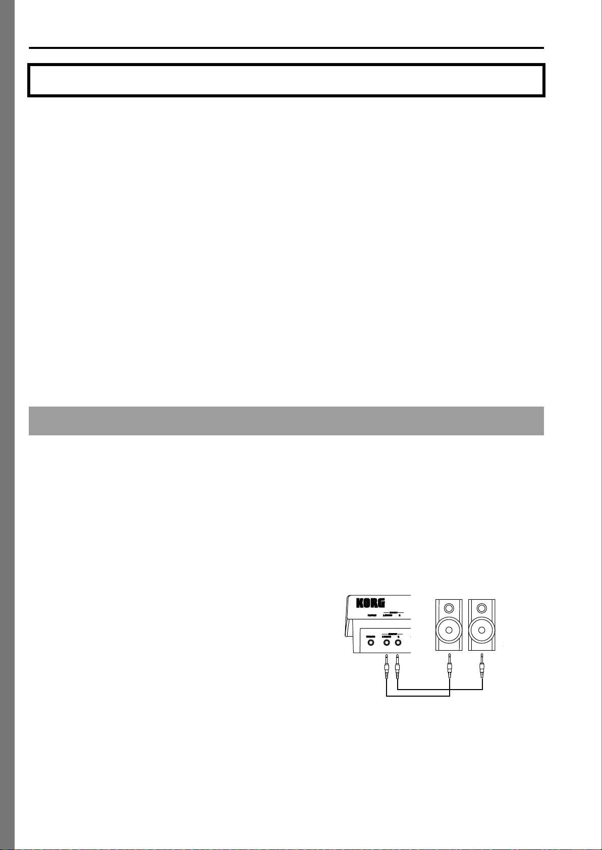
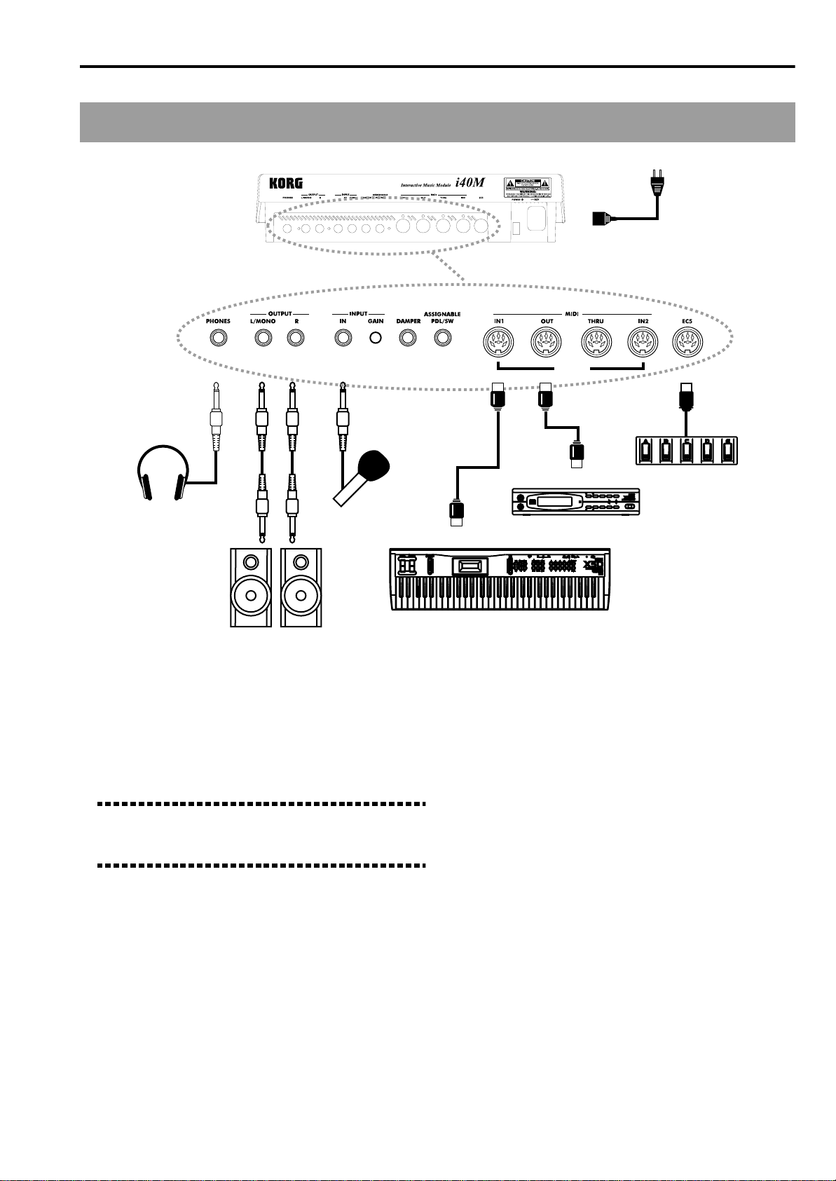
Connecting an external
amplifying system
You can connect the i40M to a professional amplifying
system (mixer or amplified speakers) or to a hi-fi system. For more information see “Rear panel” on
page 13.
Connecting the i40M to a mixer (or to
two amplified diffusers)
Connect the OUTPUT jacks of the i40M to two mono
inputs of the mixer (or to the speaker inputs) using
two audio cables with mono jacks. To take the signal in
mono, connect the LEFT/MONO output only and one
channel of the mixer using an audio cable. For more
information refer to the user’s guide of the mixer (or
the speakers).
2
Page 11
Getting Started • Introduction
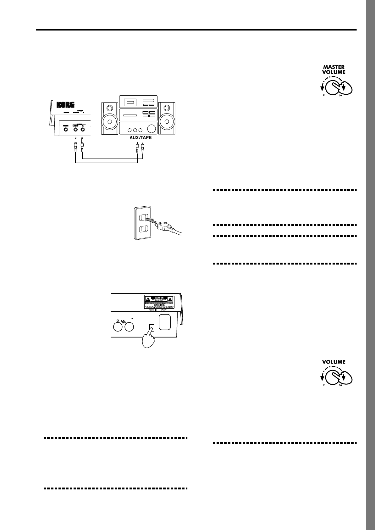
Connecting the i40M to a hi-fi system
Connect the OUTPUT jacks of the i40M to the AUX or
TAPE inputs of the amplifier using two audio cables
with a mono jack at one end and an RCA connector at
the other end (do not use the PHONE or TUNER
inputs).
Connecting the power cable
●Plug the power cable into
the power socket.
Make sure that the mains
voltage is suitable for the
instrument (the voltage is
indicated next to the AC
power inlet).
Adjusting the general volume
●Use the MASTER VOLUME knob
to adjust the general volume of
the internal sound generation.
Moving the knob towards “10” will
increase the volume, and moving it
towards the “0” will decrease the
volume. In the “0” position the instrument will be
mute.
If you are connected to an external amplifying system, you should at this point turn the volume of the
mixer or the speakers up and then adjust both the
volume of the i40M and that of the speakers.
The MASTER VOLUME knob controls the level of
the internal sound generation both of the OUTPUT
jacks and the headphones.
Note: This knob does not control the volume of the
VOCAL/GUITAR section (input signal from the INPUTIN jack). Use the VOLUME knob to adjust the level of
this section.
Warning: At the maximum volume the sound can be
distorted. Should this happen, decrease the volume of
the i40M.
Turning on the power
●Press the POWER
switch to turn the
instrument on.
On turning on, the
instrument will be in
the Arrangement
Play mode. If you
are connected to an
external amplifying
system, turn the speakers on only after having
switched on the i40M.
●To turn the instrument off, press the POWER
switch again.
In order to save on electricity, turn the instrument
off when you are not using it. Do not turn the
power off while the disk indicator is lit or while a
message such as “Loading”, “Saving” or “Formatting” is shown on the LCD display.
Note: When the instrument is turned off, all the data
contained in the RAM memory will be lost (e.g. backing sequence and song). On the contrary, USER styles,
USER arrangements and USER programs are
retained. Before turning the instrument off, save backing sequence (☞P. 33) and song (☞P. 35) on disk.
Adjusting the volume of the
Vocal/Guitar section
The VOCAL/GUITAR section takes the input signal
from the INPUT-IN jack and process it with dedicated
effects. The processed signal is combined with the
sounds generated by the internal sound generation
and comes out from the OUTPUT jacks.
●Use the VOLUME knob to adjust
the volume of the section.
Moving the knob towards “10” will
increase the volume, and moving it
towards the “0” will decrease the
volume. In the “0” position the VOCAL/GUITAR
section does not reach the OUTPUT jacks.
The VOLUME knob controls the level of the
VOCAL/GUITAR section both of the OUTPUT
jacks and the headphones.
Note: Use the GAIN knob located next to the INPUTIN jack to adjust the input level at best. Connect the
instrument, start playing and check the color of the
SIGNAL led on the control panel: if it is red, distortion
is present and the gain must be decreased; if it is
orange, distortion is close and the gain should be
3
Page 12
Getting Started • Introduction
decreased slightly; if it is green, the level is correct. If
the led does not light up, the input level is too low and
the gain must be increased.
Suggestion: If the INPUT-IN jack is not used, set the
volume on zero to avoid any interference or residual
noise.
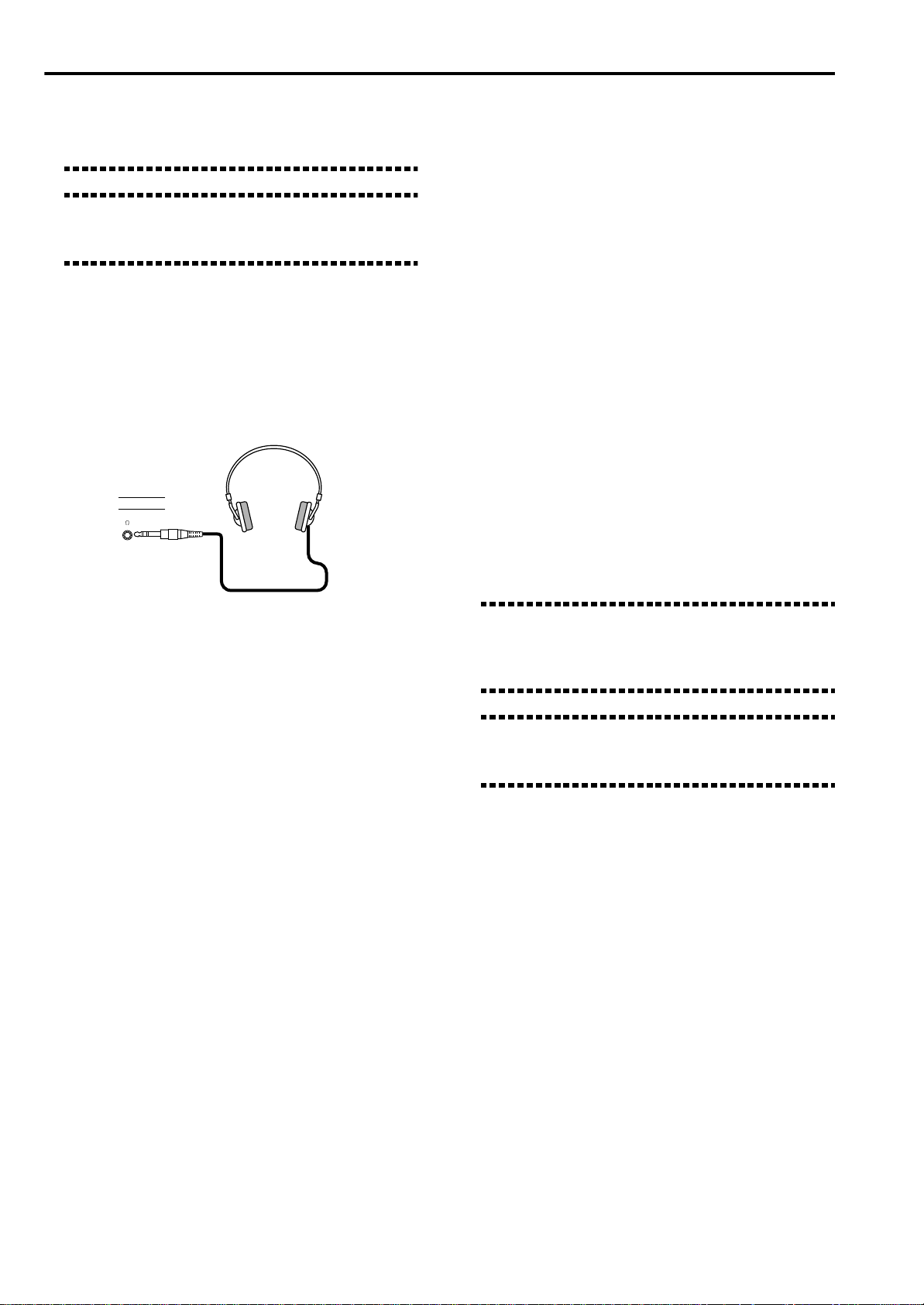
The headphones
●Connect the headphones to the PHONES jack
located on the rear panel.
Use stereo headphones with a standard jack. Adjust
the volume with the MASTER VOLUME knob.
page 44. Let’s now illustrate two of the most common
situations: connecting a MIDI keyboard and connecting a MIDI accordion.
Connecting a MIDI keyboard
The i40M can be controlled with any MIDI keyboard,
such as a master keyboard or a synthesizer with MIDI
OUT jack.
1 Connect the MIDI OUT jack of the MIDI key-
board to the MIDI IN 1 jack of the i40M using a
standard MIDI cable.
2 Program the keyboard to transmit over the MIDI
1 channel.
According to the factory settings, the MIDI 1 channel is the channel used by the i40M to receive most
information. For example, channel 1 corresponds to
Global that allows for using all the functions
related to the split point (Keyboard Mode section).
For more information on Global programming, see
“MIDI” on page 44 and the “GLB (Global)” on
page 139.
Connecting a MIDI controller
For live performances the i40M must be connected to a
MIDI controller, such as a MIDI keyboard, a digital
piano, a MIDI accordion, a guitar controller, a wind
controller, a set of percussion pads or an external
sequencer. For detailed information see “MIDI” on
Note: If the keyboard transmits over the MIDI channel dedicated to the i40M Global, the keyboard
becomes the integrated keyboard of the i40M. The
i40M becomes virtually your keyboard instrument.
Suggestion: If the keyboard does not transmit over
the Global channel, see “MIDI” on page 44 for more
information.
4
Page 13
Getting Started • Introduction
Connecting a MIDI accordion
You can connect a MIDI accordion and play a track of
the i40M with each section.
1 Connect the MIDI OUT jack of the MIDI accor-
dion to the MIDI IN 1 jack of the i40M using a
standard MIDI cable.
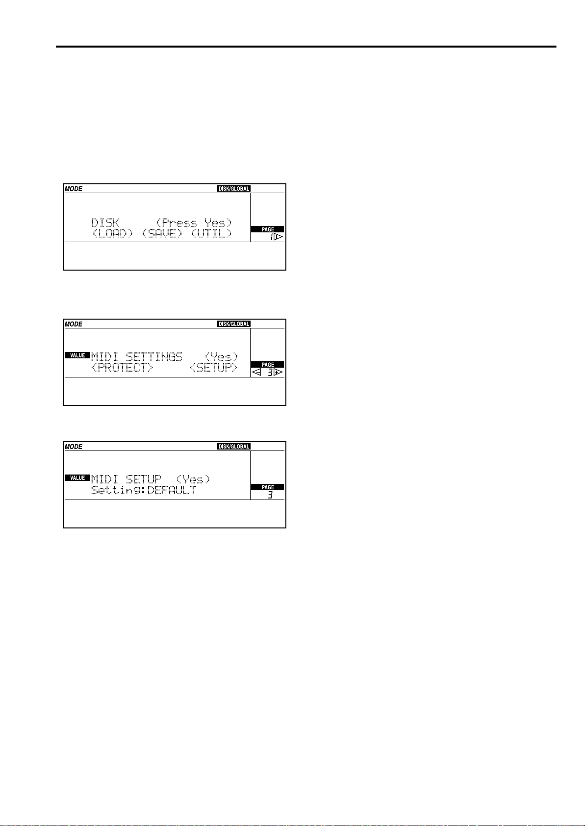
2 Press DISK/GLOBAL.
3 Press the PAGE [+] button repeatedly to access
the MIDI Settings page.
MIDI SETTINGS (Yes)
<PROTECT> <SETUP>
• “Accordion 1” is designed for those who have an
accordion with three fixed channels. This setup is
also suitable for backing sequence recording.
• “Accordion 2” is designed for those who have an
accordion with two channels on the right hand and
do not want to play the bass of the i40M.
• “Accordion 3” is designed for those who have an
accordion with two channels on the right hand,
want to play the bass of the i40M and have another
channel to change the Arrangements of the i40M
with Program Change.
For more information on the MIDI Setups, see
“MIDI” on page 44 and the “Page 3: MIDI Settings”
on page 136.
6 Press ENTER/YES twice to confirm the MIDI
Setup selection.
The configuration of the MIDI channels and of the
other parameters selected with the MIDI Setup will
be retained until the configuration is manually
changed.
7 Press REC/WRITE/LYRICS and then ENTER/YES
twice.
The automatic settings of the MIDI Setup are saved
in Global and will be available also after turning
the instrument off and on again.
4 Press CURSOR [>] to select <SETUP>.
MIDI SETUP (Yes)
Setting:DEFAULT
5 Press the TEMPO/VALUE [+] to select one of the
MIDI “Accordion” setups.
There are three “Accordion” setups.
Connecting other MIDI controllers
The MIDI configuration may vary according to the
type of controller connected to the i40M. To automatically re-configure the i40M select a MIDI Setup (see
“MIDI” on page 44 and the “Page 3: MIDI Settings” on
page 136).
5
Page 14
Getting Started• Front and Rear Panels
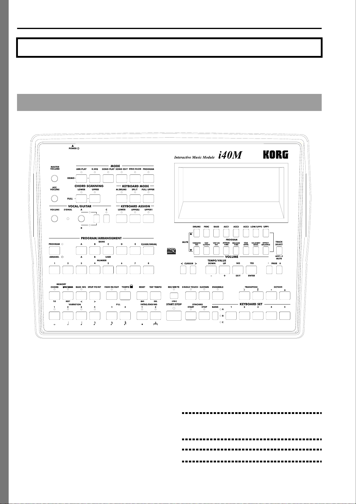
2. Front and Rear Panels
Front Panel
4
6
5
@
7
8
9
A
IJKL MN OP
WXY
B
DEFGH
Q
RST U V
Z[
1
C
3
2
\
1 Display
The editing pages, parameters and messages for the
user will appear in this display.
2 Floppy disk drive slot
3.5 inch double-sided double density (2DD) or double-sided high density (HD) floppy disks can be
inserted in this drive. You can use Korg i-series formatted floppy disks and standard Ms-Dos® formatted floppy disks.
The i40M incorporates a disk drive without auditory
feedback (i.e. the “click” when the disk has been
pressed all the way in).
3 Disk eject button
Press this button to remove a floppy disk from the
drive. If pressing this button does not eject the disk,
6
do not try to force it out. Contact your dealer or
nearest Korg Service Station.
4 MASTER VOLUME knob
Output level of internal sound generation (OUTPUT
outlets and headphones).
This control does not adjust the level of the VOCAL/
GUITAR section (input signal through INPUT-IN).
Warning: Volume that is too high can cause serious
harm to your hearing. Keep the volume at a moderate
level.
Note: At higher volumes the sound can be distorted.
Page 15

Getting Started • Front and Rear Panels
5 ACC.VOLUME knob (Accompaniment Volume)
Automatic accompaniment volume. In Song Play
and Song Edit modes it controls the volume of all
tracks, except the one selected (whose volume
remains constant).
6 MODE section
The buttons in this section activate the operating
modes of the instrument (see chapter “Operative
modes” on page 15).
• ARR. PLAY (Arrangement Play) button
This button accesses the Arrangement Play mode.
(The instrument is automatically in this mode when
it is turned on). With this mode you can use the automatic accompaniments.
• B.SEQ (Backing Sequence) button
This button accesses the Backing Sequence mode.
With this mode you can record or playback musical
performances played with automatic accompaniments.
• SONG PLAY button
This button accesses the Song Play mode. With this
mode you can directly playback musical performances in Standard MIDI File (SMF) format without
loading them from disk.
You can also read the SMF lyrics in the display (Lyrics function). The display mode can be selected with
the REC/WRITE/LYRICS button.
• SONG EDIT button
This button accesses the Song Edit mode. With this
mode you can record, playback, edit and save a Standard MIDI File (SMF).
• DISK/GLOBAL button
This button accesses the Disk/Global mode. With
this mode you can load and save data from a floppy
disk, and program some of the instrument’s general
settings (e.g. pedals and MIDI channels).
• PROGRAM button
This button accesses the Program mode. With this
mode you can play and edit the single programs
(single sounds).
PROGRAM/ARRANG to light up the ARRANG led,
and press a NUMBER 1-8 button.
To select a demo from 9 to 16, press PROGRAM/
ARRANG to light up the PROGRAM led and press a
NUMBER 1-8 button.
Press START/STOP to stop the demo playback.
How to exit the Demo mode. To exit the Demo
mode either press EXIT/NO or the button of one of
the operating modes (MODE section).
7 CHORD SCANNING section
Arrangement Play and Backing Sequence modes:
this section specifies which area of the keyboard will
be used to detect chords for the automatic accompaniment. To activate the FULL mode it is necessary to
light the leds of both LOWER and UPPER buttons.
• LOWER button
Chords will be detected in the Lower range (below
the split point). The chord recognition mode is
defined by the “ChordRecog (Chord recognition
mode)” parameter of the Disk/Global mode (see
page 147).
• UPPER button
Chords will be detected in the Upper range (above
and including the split point). The recognition mode
is automatically set at Fingered 2 (see page 147).
• FULL (LOWER + UPPER) buttons
Chords will be detected in the entire range. The recognition mode is automatically set at Fingered 2 (see
page 147).
• OFF (unlit leds)
Chords are not detected. If the leds are off, when
pressing START/STOP to start the accompaniment,
you can only listen to the Drum and Perc tracks. The
other accompaniment tracks do not play.
8 KEYBOARD MODE section
If the i40M is connected to a keyboard through the
Global channel, these buttons can be used to select
the set-up of the tracks on the keyboard in the
Arrangement Play e Backing Sequence modes.
• DEMO buttons
Press both ARR.PLAY and B.SEQ to access the Demo
mode where you can listen to 16 demo pieces.
How to listen to all demos consecutively. To listen
to all demo pieces consecutively access the Demo
mode and press START/STOP. To stop the demo
playback press START/STOP.
How to listen to a single demo. To listen to a single
demo, access the Demo mode and select it. The
demo playback starts immediately.
To select a demo use the buttons of the PROGRAM/
ARRANG section. To select a demo from 1 to 8, press
Note: This section is particularly dedicated to the connection of the i40M to a MIDI keyboard. It only works if
the MIDI controller transmits over the special Global
channel (see page 45).
• M.DRUM button
A different percussion sound is assigned to each
note of the keyboard.
• SPLIT button
The right hand (Upper 1 and Upper 2) and the left
hand (Lower) play different sounds and are separated by the split point. The Upper 2 and Lower
tracks are alternative, one excludes the other on the
keyboard.
7
Page 16
Getting Started• Front and Rear Panels
• FULL UPPER button
One or two tracks (Upper 1 and/or Upper 2) play on
the entire keyboard.
9 KEYBOARD ASSIGN section
These buttons select the realtime tracks (Upper 1,
Upper 2, Lower) in the Arrangement Play and Back-
ing Sequence modes. The Upper 2 and Lower are
alternative, one excludes the other on the keyboard.
10 VOCAL/GUITAR section
The VOCAL/GUITAR section applies effects to the
signal of a microphone, a guitar or a line source
(mono) coming to the INPUT-IN connector. The signal is then mixed with the sound of the internal
sound generation and sent to the OUTPUT outlets.
In Vocal mode it harmonizes the voice with the notes
received over the MIDI channel dedicated to harmonisation. According to the factory settings, the
notes are received over channel 5.
The VOCAL/GUIT AR section works in the Arrangement Play, Backing Sequence and Song Play modes.
The settings are saved in the Keyboard Set. See “The
Vocal/Guitar section” on page 39.
• VOLUME knob
It controls the level of the VOCAL/GUITAR section
on the OUTPUT outlets.
Note: When you turn the instrument on, the VOCAL/
GUITAR section is deactivated. Select one of the Keyboard Sets to activate it. If you have connected a microphone, choose a Keyboard Set in the bank A. If you
have connected a guitar, choose a Keyboard Set in the
bank B (clean settings) or C (overdrive settings).
11 PROGRAM/ARRANGEMENT section
These buttons are used to select programs and
arrangements.
To select a program (single sound) press PROGRAM/ARRANG to light the PROGRAM led. Press
one of the BANK (A, B, C, D, E, F) buttons to choose
the bank, then select a two-digit number between 11
and 88 using the NUMBER buttons to choose the
program.
To select the DRUM bank press twice the F(USER/
DRUM) button until the abbreviation “Dr” shows in
the display. The Drum programs range from Dr11 to
Dr28.
To select an arrangement, press PROGRAM/
ARRANG to light the ARRANG led. Press one of the
BANK (A, B, USER) buttons to choose the bank, then
select a two-digit number between 11 and 88 using
the NUMBER buttons to choose the arrangement.
• SIGNAL led
The SIGNAL led changes color according to the signal level. If it is off, there is no signal or the signal
level is very low. If it is green the signal is present. If
it is orange, the signal is close to saturation. If it is
red, the signal is saturated.
Warning: The signal cannot be saturated. If the led is
red, adjust the input gain with the GAIN knob in the
control panel.
• A/B switch button
It selects the operating mode of the A/B switch
between A and B.
• A/B knob
Programmable knob. It controls the value of the
parameter assigned to the A or B function (see
page 65). The A or B operating mode can be selected
with the A/B switch button.
Note: The knob does not work until the last value of
the controlled function is reached. For example, if the
knob is on “0” and the current parameter value is “5”,
the knob will not work until it reaches “5”.
• C button
Programmable button. It can act as “mute” for the
VOCAL/GUITAR section, the effects or the harmonisation.
If the program or arrangement to be selected belongs
to the same bank of the selected program or arrangement, only select the two-digit number without
pressing the BANK button.
In the Arrangement Play mode you can use the
Arrangement Preview and Program Preview functions to show the program or arrangement name in
the display before selecting it.
Press a BANK button, if necessary press a NUMBER
button to select the tens, then select the program or
arrangement using the TEMPO/VALUE buttons
and press ENTER/YES to confirm.
12 VOLUME/PROGRAM buttons
These buttons are normally used to adjust the track
volume of the tracks and to mute it. To raise the volume press the upper button, to lower it press the
lower button. To mute a track press the upper and
lower button together. To take off the mute, press
one of the buttons briefly.
Arrangement Play mode: these buttons select the
tracks and change the volume. When a track has
been selected you can set a different program for
that track (see PROGRAM/ARRANG section).
Backing Sequence mode: these buttons select the
tracks and change the volume. To select the Extra
Tracks first press the TRACK SELECT button and
then the VOLUME buttons.
Song Play mode: these buttons select the MIDI channels (tracks) of the SMF and change the volume. To
8
Page 17

Getting Started • Front and Rear Panels
go from channels 1-8 to channels 9-16 (and vice
versa) press the TRACK SELECT button.
Song Edit mode: these buttons select the tracks and
change the volume. To go from tracks 1-8 to tracks 916 (and vice versa) press the TRACK SELECT button.
Program mode: these buttons modify the value of
the parameters indicated under each button.
13 TRACK SELECT button
Arrangement Play mode: mutes the ACC1, ACC2,
ACC3 tracks.
Backing Sequence mode: switches between the
arrangement tracks and the Extra Track.
Song Play mode: switches between the channels 1-8
and the channels 9-16 of the SMF. (In Song Play
mode channels and tracks are the same).
Song Edit mode: switches between tracks 1-8 and
tracks 9-16.
14 CURSOR buttons
These buttons move the cursor among the parameters that appear in the display. Before modifying the
value of a parameter, the cursor must be positioned
on the value that needs to be modified (flashing
text).
17 ENTER/YES button
By pressing this button you can give a positive reply
to questions that may appear in the display and to
start some operations in the Disk/Global mode
(Load, Save, Format, MIDI Setup…).
Song Play mode: by pressing this button when the
cursor is on the name of a song, the song will be
inserted in the JukeBox list and the JukeBox mode
activated.
18 PAGE buttons
These buttons select the previous (-) or the next (+)
page in the current mode. The page number appears
on the right of the display. Two arr ows appear befor e
or after the number to indicate the presence of previous (<) or next (>) pages.
If no arrows appear before and after the page number, you are in a subpage of the Disk/Global mode.
To exit press EXIT/NO (see page 19).
19 MEMORY-CHORD/TIE button
Arrangement Play and Backing Sequence modes:
keeps the accompaniment chord after taking your
hand off the keyboard.
Backing Sequence-Step Recording mode: inserts a
tie (ties the last note played to the next note that is
going to be played).
15 TEMPO/VALUE buttons
These buttons modify the tempo or the parameter
value selected in the display. The TEMPO or VALUE
indicators show up in the display when they are
functioning.
16 EXIT/NO button
This button is used to go back to Page 1 of the current operative mode and to return to the higher level
from the subpages (pages in which the indication of
previous or next page is not shown next to the number page).
The second function (NO) is to be used to give a negative reply to questions that may appear in the display.
Arrangement Play, Backing Sequence and Song
Play modes: takes you back to Page 1 of the mode.
Page 1 of the Arrangement Play mode: calls up the
settings of the realtime tracks saved in the Arrangement.
Song Play mode: takes you back to the previous
page after pressing a VOLUME/PROGRAM button
to choose a track.
Song Play-JukeBox mode: makes you exit from the
JukeBox mode.
Song Edit mode: calls up Page 2 of the mode.
Disk/Global mode subpages: takes you back to the
top page.
20 MEMORY-LOW/HAR/REST button
Arrangement Play and Backing Sequence modes: if
the Lower track is controlled by the Global channel,
this button keeps the Lower track notes after taking
your hands off the keyboard. (See “Page 14: Lower
memory” in the Disk/Global mode).
Arrangement Play, Backing Sequence, Song Play
modes: keeps the harmonization notes coming over
the Harmony channel (see page 142 and following).
Backing Sequence-Step Recording mode: creates a
pause.
21 BASS INV./< (Bass Inversion/backwards) button
Arrangement Play and Backing Sequence modes:
with this function the lowest note of a chord played
in inverted form will always be detected as the main
note of the chord. Thus, you can specify to the
arranger composite chords such as Am7/G or “F/
C”. When the Chord Scanning is FULL, the bass note
will not change until another bass note is played.
Backing Sequence-Step Recording mode: this button is used to go to the previous step.
22 SPLIT POINT/> (Split Point/Forward) button
Arrangement Play and Backing Sequence modes:
selects the split point (division of the keyboard).
Hold down the button and play the note you wish to
become the split point. This note and all the notes to
the right of it are part of the Upper range, the notes
to its lefts are part of the Lower range.
9
Page 18
Getting Started• Front and Rear Panels
The split point can be saved in the Global in order to
remain available also after you turn the instrument
off and on again. (See “Page 22: Write Global” on
page 152).
Note: The split point is particularly useful when the
i40M is connected to a MIDI keyboard. It only works if
the MIDI controller transmits through the special Global
channel (see page 45).
Backing Sequence-Event Editing mode: goes to the
next step.
23 FADE IN/OUT button
If the accompaniment is not playing, this button
fades it in (the volume gradually increases from zero
to the maximum value). If the accompaniment is
playing, this button fades it out (the volume gradually decreases from the maximum value to zero). You
do not need to press START/STOP to start or stop
the accompaniment.
24 TEMPO (Tempo Lock) button
Led lit up: when you change the arrangement the
tempo will not change. The tempo can be manually
changed by using the TEMPO/VALUE buttons.
25 RESET/INS button
Backing Sequence, Song Play, Song Edit modes:
this button returns the sequencer to the first measure.
Arrangement Play and Backing Sequence modes:
restarts the chord scanner and returns to the beginning of the measure.
The second function of the (INS) button is to insert a
Step Recording event, or an empty space where the
cursor is positioned when you wish to write a name.
Note: In any situation this button can be used as “MIDI
Panic”. Press it when a note gets stuck to unblock it.
26 TAP TEMPO/DEL button
You can set the tempo with this button. The tempo is
updated in the display.
The second function of the (DEL) button is to cancel
the event that has been selected in Step Recording,
or to cancel a letter where the cursor is positioned
when you wish to write a name.
27 REC/WRITE/LYRICS
(Recording/Writing/Lyrics) button
Backing Sequence and Song Edit modes: this button enters the record mode.
Arrangement Play and Program modes: this will
access the W rite page where you can save your modified Arrangement, Keyboard Set o program.
Song Play mode: switches through the display
modes Lyrics 1 (lyrics 1), Lyrics 2 (lyrics 2), Play
(standard execution information).
Note: The Lyrics modes are only available if the SMF
contains the lyrics. The Lyrics 2 mode is only available
with some SMF.
Global mode: recalls the Write Global page.
28 SINGLE TOUCH button
Led lit up: when an arrangement is changed, the
programs of Upper 1, Upper 2 and Lower tracks are
recalled and saved in the new arrangement.
29 SUSTAIN button
Arrangement Play, Backing Sequence, Program,
Song Play modes: increases the length of the notes
(by extending the program sustain).
30 ENSEMBLE button
Arrangement Play and Backing Sequence modes:
harmonizes the melody played with your right hand
with the chords played with your left hand. The
Chord Scanning must be LOWER.
31 TRANSPOSE buttons
These buttons change the transposition (in semitones) of the instrument. The transposition value
temporarily appears on the right side of the display.
In order to cancel the transposition you must press
both buttons together.
32 OCTAVE buttons
These buttons change the transposition (in octaves)
of the track selected in the display. In order to cancel
the transposition you must press both buttons
together.
33 VARIATION 1, 2, 3, 4 buttons
Arrangement Play and Backing Sequence modes:
these buttons select one of the four style variations.
Backing Sequence-Step Recording mode: these button are used to specify the length of the note being
input (the value of the notes is shown under the buttons).
34 FILL 1/2 (Fill-in) buttons
Arrangement Play and Backing Sequence modes:
pressing one of these buttons during performance
will add a fill-in.
Backing Sequence-Step Recording mode: these buttons are used to specify the length of the note being
input (the value of the notes is shown under the buttons).
35 INTRO/ENDING buttons
Arrangement Play and Backing Sequence modes:
pressing one of these buttons before you begin playing will cause an introduction to be played after you
press START/STOP. Pressing one of these buttons
during a performance will cause an ending to be
10
Page 19

Getting Started • Front and Rear Panels
played, after which the performance will end automatically.
Backing Sequence-Step Recording mode: these buttons are used to specify the length of the note being
input (the value of the notes is shown under the buttons).
36 START/STOP button
Arrangement Play, Song Play and Demo modes:
this button starts or stops the automatic accompaniment or playback.
Backing Sequence and Song Edit modes: it starts or
stops playback. If the REC/WRITE/LYRICS led is lit
up, it starts or stops recording.
37 SYNCHRO-START and SYNCHRO STOP buttons
The SYNCHRO-START button makes the accompaniment start when you play a note or chord in the
chord detection area of the keyboard, without having to press START/STOP.
The SYNCHRO-STOP button makes the accompaniment stop when the hand playing the notes in the
chord detection area of the keyboard is taken off the
keyboard.
select the set-up of the realtime tracks (Upper 1,
Upper 2 and Lower), the effects and the settings of
the VOCAL/GUITAR section.
In Song Play mode the Keyboard Set only select the
settings of the VOCAL/GUITAR section (and not
the track set-up).
To choose a Keyboard Set you have to press once, or
repeatedly BANK to choose bank A, B or C, then you
must press one of the number buttons to choose the
Keyboard Set.
In Arrangement Play you can save the current set-
up of the realtime tracks, the effects and the settings
of the VOCAL/GUITAR section in a Keyboard Set.
1. Press REC/WRITE/LYRICS.
2. Press one of the buttons in the KEYBOARD SET
section to recall the Write Keyboard Set page.
3. Press once, or repeatedly BANK to choose the
bank (A, B or C).
4. Press the number button which corresponds to
the Keyboard Set where you wish to save the setup.
38 KEYBOARD SET section
By pressing only one button in Arrangement Play
and Backing Sequence modes the Keyboard Set
5. Press ENTER/YES twice to confirm.
11
Page 20

Getting Started• Front and Rear Panels
Display
1
6
2
7
8
1 Mode
The first line of the display indicates the operative
mode: ARR.PLAY, BACKING SEQ., SONG PLAY,
SONG EDIT, DISK/GLOBAL, PROGRAM.
2 Tempo/Value
The two indicators TEMPO and VALUE show in
alternation. They show the functioning of the
TEMPO/VALUE buttons. If these buttons act as
tempo controls the display shows TEMPO. If they
act as modifiers of the selected parameter the display
shows VALUE.
3 Split
Indicates that the SPLIT POINT button is currently
pressed, and the note shown below in the display is
the currently selected split point.
4 Transpose/Octave
The two indicators TRANSPOSE and OCT AVE show
in alternation. According to which one shows, the
value below indicates the transposition value by
semitones or octaves.
5 Page
Indicator of the current page. If [>] shows, there are
pages to follow. If [<] shows there are previous
pages. Go through the pages with the PAGE [+] and
[-] buttons.
6 Tempo
Current tempo. If the TEMPO indicator is showing,
you can vary the tempo with the TEMPO/VALUE
buttons.
7 Tempo mode/Clock (synchronization)
Tempo mode and type of synchronization.
3
4
5
9
10
AUTO means that the sequencer is reading the
tempo recorded in the song.
EXT means that the i40M is synchronized with the
metronome of an external device connected to its
MIDI IN. Only one of the MIDI IN connectors of the
i40M can receive the synchronism (see page 137).
You can choose the kind of synchronism you require
on “Page 4: Global MIDI parameters” of the Disk/
Global mode.
8 Chord name
9 Modifiable parameters
Two lines of characters that show the parameters of
the various edit pages. You can move through the
parameters with the CURSOR buttons and modify
the values with the TEMPO/VALUE buttons.
10 Volume indicators
Track volume. The tracks that are selected are shown
at the top and on the left:
none = accompaniment and realtime tracks shown
above the PROGRAM/VOLUME buttons
(Arrangement Play, Backing Sequence)
ET = Extra Track (Backing Sequence)
ch = channels (Song Play)
1-8 = tracks/channels 1-8 (Song Play, Song Edit)
9-16 = tracks/channels 9-16 (Song Play, Song Edit)
To select the hidden tracks press TRACK SELECT. If
all the indicators are off, the realtime and accompaniment tracks indicated above the VOLUME/PROGRAM buttons are shown.
12
Page 21
Rear panel
Getting Started • Front and Rear Panels
9@
1 2 3456
1 PHONES jack
You can connect a stereo headphones here.
2 OUTPUT connectors
Audio outlets. You can connect an amplifier here.
You can connect the i40M to a mixer, two amplified
speakers or the AUX/TAPE inlet of an hi-fi system.
If the amplifier is mono, only connect the L/MONO
connector.
78
MIDI IN
MIDI OUT
The signal can never be saturated. If the red led
lights up, adjust the GAIN knob in order to reduce
the input gain.
4 GAIN knob
Adjusts the gain of the INPUT-IN inlet. Turn it
towards the left to reduce the gain (e.g. when the
SIGNAL led is orange or red), and towards the right
to increase it.
EC5
Warning: Volume that is too high can cause serious
damage to your hearing. Keep the volume at a moderate level.
3 INPUT-IN connector
Audio inlet for microphone, guitar or mono line signal. The signal goes through the effects and the harmonizer of the VOCAL/GUIT AR section, and comes
out from the OUTPUT outlets (together with the
sounds of the internal sound generation of the
i40M).
Set the input level with the GAIN knob. The presence of the signal lights up the green SIGNAL led. If
the signal is close to saturation, the led becomes
orange. If the signal is saturated, the led becomes
red.
5 DAMPER connector
You can connect a damper pedal here, such as Korg
DS-1 or similar. The damper pedals can have a different polarity; choose the polarity of your pedal on
“Page 16: Auto chord scanning/Damper polarity” in
the Disk/Global mode (see page 148).
6 ASSIGNABLE PDL/SW connector
You can connect an expression pedal here, such as
Korg XVP-10 or EXP-2, or a PS-1 or PS-2 type footswitch. You can program the function assigned to
the pedal on “Page 12: Assignable pedal/switch” in
the Disk/Global mode (see page 143).
7 MIDI connectors
You can connect other MIDI devices (keyboards or
computers) here. For the connection you need the
special MIDI cables which you can purchase from
your Korg dealer. (See chapter “MIDI” on page 44).
13
Page 22

Getting Started• Front and Rear Panels
• MIDI IN 1 and MIDI IN 2 connectors
Receive MIDI data from external devices. The two
connectors are identical and can be used, for
instance, to simultaneously connect a keyboard to
MIDI IN 1 and an accordion to MIDI IN 2. The synchronism signal (MIDI Clock) can only be received
by one connector at a time (see “Clock (Clock
source)” on page 137).
• MIDI OUT connector
Transmits the MIDI data generated by the i40M to
other devices.
• MIDI THRU connector
Re-transmits the MIDI data received by the MIDI IN
1 and 2 ports.
8 EC5 connector
You can connect an optional Korg EC5 external controller here. You can program the EC5 on “Page 13:
EC5 external controller” in the Disk/Global mode,
assigning a function to each of the five pedal
switches.
9 POWER switch
On/off switch.
10 Power supply connector
Plug the power cable supplied with the instrument
here.
Warning: Always connect the instrument to a power
socket with ground.
14
Page 23

3. Operative modes
Getting Started • Operative modes
The instrument can function in different “modes”,
each of which groups together functions that are for its
Arrangement Play mode
Arrangement Play is the main operative mode. When
the instrument is turned on, it is always in this mode,
where you can select the arrangements and the Keyboard Set you wish to use.
There are 192 arrangements in total, organized as 64
arrangements in each of the three banks A, B, and
USER. The arrangements in the USER bank are freely
modifiable and can be used to load new data from a
disk.
The 15 Keyboard Set are all freely modifiable and
divided in three banks with 5 Keyboard Set each. The
Keyboard Set are designed to immediately change the
programs of the real time tracks and the settings of the
VOCAL/GUITAR section.
Each arrangement is composed of a style and three
real time tracks (Upper 1, Upper 2, and Lower). The
real time tracks can be played “live” with the accompaniment of the style tracks.
The way in which the real time tracks are arranged on
a MIDI keyboard and their activation/deactivation
state are set in the KEYBOARD MODE and KEYBOARD ASSIGN sections.
The styles are made up of patterns (musical structures)
used to create the automatic accompaniments. Each
style contains four variations, two intros (introductions), two endings and two fill-ins (passages).
The style selected by the arrangement detects the type
of chord played in a section known as “chord detection section” and adapts its pattern to that chord. For
example, if the pattern is in C major, playing a F major
own particular use. In order to choose a mode you
need to press a button in the MODE section.
chord in the chord detection section will cause the pattern transposition to F major.
The way in which patterns are affected by chords is of
course more complex than what indicated above. Korg
instruments are renowned for their refinement in
detecting the chords.
The styles consist of six tracks: drums, percussion,
bass, accompaniment tracks ACC1, ACC2 and ACC3.
These six tracks are referred to as the Backing Tracks,
since they provide the rhythmical and harmonic backing of the song.
Whilst playing you can modify several arrangement
parameters (e.g. the volume of the instrumental parts),
however if you stop the accompaniment, or decide to
select a different arrangement, your edits will be lost.
To save the changes in the USER bank use the Write
Arrangement of the “Page 24: Write Arrangement”
(see page 79).
To save the changes in the Keyboard Set use the Write
Keyboard Set function of the “Page 25: Write Keyboard Set” (see page 80).
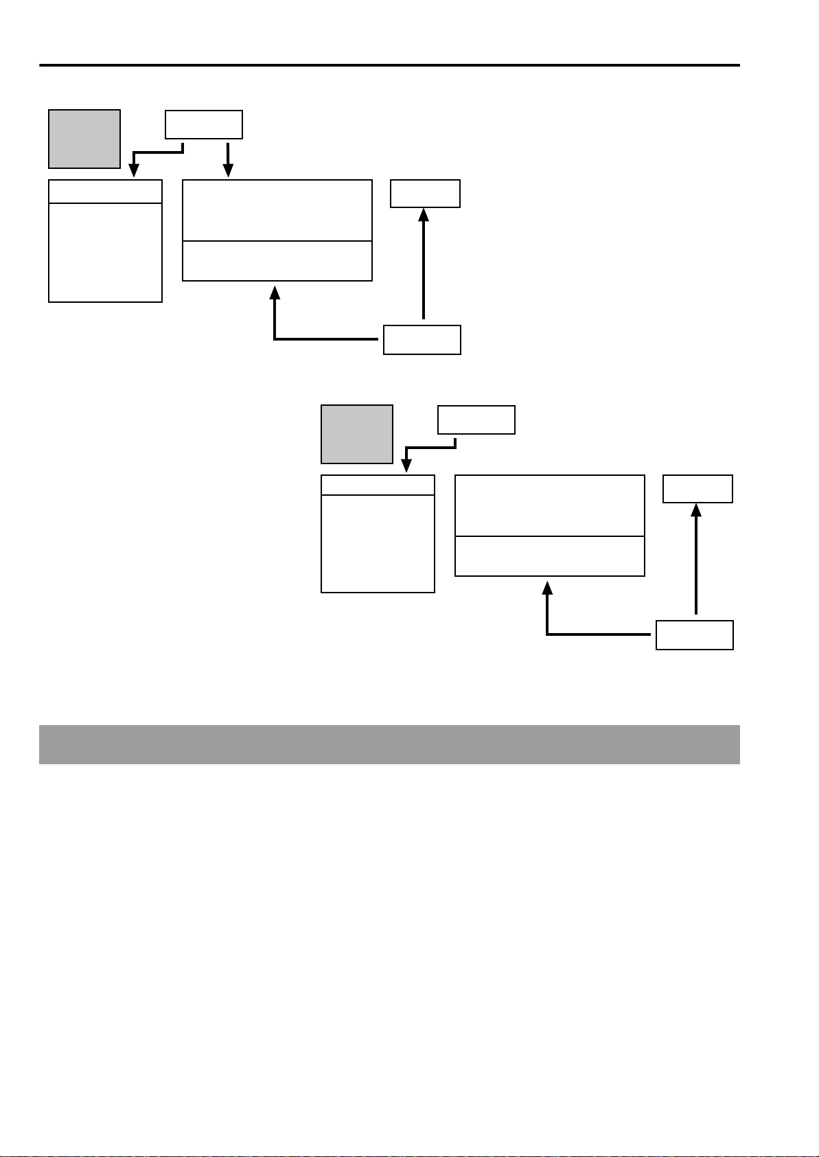
The following scheme shows the parameters that are
automatically changed when selecting an arrangement
or Keyboard Set:
• if the SINGLE TOUCH led is on, the arrangement
can also change the parameters of the real time
tracks;
• if the SINGLE TOUCH led is off, the arrangement
can only change the parameters of the accompaniment tracks.
15
Page 24
Getting Started • Operative modes
SINGLE
TOUCH
ON
Style
Acc. tracks (prog, vol,
pan, fx send, octave)
Outputs
Wrap around
Drum map
Snare/kick designation
Ensemble
Fill mode
Tempo
Arrangement
Keyboard assign
Keyboard mode
Chord scanning
Keyboard scale
Master fx
Upper 1 (prog, vol, pan, fx send, octave)
Upper 2 (prog, vol, pan, fx send, octave)
Lower (prog, vol, pan, fx send, octave)
Vocal/Guitar
Keyboard Set
SINGLE
TOUCH
OFF
Style
Acc. tracks (prog, vol,
pan, fx send, octave)
Outputs
Wrap around
Drum map
Snare/kick designation
Ensemble
Fill mode
Tempo
Arrangement
Keyboard assign
Keyboard mode
Chord scanning
Keyboard scale
Master fx
Upper 1 (prog, vol, pan, fx send, octave)
Upper 2 (prog, vol, pan, fx send, octave)
Lower (prog, vol, pan, fx send, octave)
Vocal/Guitar
Backing Sequence mode
The Backing Sequence mode allows you to create a
song in a simple way, by recording it in real time with
the arrangements. You can playback the song in this
way or convert it in SMF and playback it in Song Play
or Song Edit mode.
The main parts of a backing sequence are the three
arrangement tracks (keyboard track, controls track
and chord track). The controls track records the button
Keyboard Set
selections of the front panel; the chord track records
the sequence of the chords; the keyboard track records
whatever is played in real time. Of course, you can
leave the keyboard track empty and play it live.
In addition to the arrangement tracks, there are eight
tracks referred to as Extra Tracks that can be used to
record other free parts for a customized arrangement.
16
Page 25

Program mode
Getting Started • Operative modes
The individual sounds played on the i40M are called
programs. The instrument has a total of 384 programs,
organized into six banks (A, B, C, D, E, F-USER) with
64 programs each, plus a DRUM bank which contains
16 Drum programs (14 ROM + 2 USER).
The programs are based on a multisample and are pr ocessed with an envelope (EG) and a digital filtering
(VDF) stage.
Song Play mode
The Song Play mode allows you to listen to songs in
Standard MIDI File format (SMF), by directly reading
them from disk, with no waiting time for loading.
The Song Play mode allows you to listen to songs
made up of 16 MID channels and is perfectly compatible with the General MIDI (GM).
This operative mode allows you to listen to new songs,
not to record them. You can change the program of the
MIDI channels, and adjust the volume, pan, effects,
In the Program mode you can edit previously recor ded
programs in order to create new programs and save
them in the USER locations. You can then use the new
programs in the arrangements, songs and backing
sequences.
In the Program mode only the special Global channel
is enabled to receive messages from an external MIDI
controller.
effect send, tempo and transpose settings. However,
the changes are not saved in memory or on disk.
In this operative mode you can read the lyrics of the
SMF in Solton, M-live (Midisoft), Tune1000 and compatible (Roland Edirol, GEM GMX, KAR, HitBit, and
Yamaha XF) format on the display. You can also read
the chord abbreviations of the SMF in Solton, M-live
(Midisoft), and GEM GMX format.
Song Edit mode
This operative mode allows you to record a new song
with the typical functions of a sophisticated sequencer.
The Song Edit mode is basically a sequence with 16
tracks. The produced SMF can be compatible with the
General MIDI (GM).
The new song can be saved on disk in Standard MIDI
File (SMF) in format 0. You can use this operative
mode to convert an SMF in format 1 into an SMF in
format 0 (that is faster to load in Song Play mode).
In addition, the Song Edit mode allows you to load
into memory, modify and save any existing SMF.
When you turn the instrument off, the song will be
canceled from memory. Therefore, before turning off
you need to save any modifications on disk (see
page 124).
17
Page 26

Getting Started • Operative modes
Disk/Global mode
The Disk/Global mode allows you to load or save
data, and modify the parameters which affect the
operation of the instrument. The operations you can
carry out are:
• Save on disk data contained in memory and load
into memory data from disk
• Tune the keyboard
• Modify MIDI settings
• Program pedals and external controllers
• Program Lower Memory
• Select a Scale (temperament)
• Control transmission/reception of MIDI messages
(data filtering)
Display pages
The parameters and functions of the various operative
modes are grouped into several pages, which appear
on the display. The page number is always indicated
on the right-hand side of the display. To move through
the display pages use the PAGE [+] and [–] buttons.
• Calibrate the pedal/footswitch
• Program the MIDI channels of the VOCAL section.
Apart from the Local Control and Clock Source
parameters, all the settings (including the split point)
can be saved in Global (with the W rite Global function,
see page 152) and will be retained when the instrument is turned off.
Global can be saved on disk and will be saved with
each Save All and Save Global operation. The split
point is not saved or loaded.
Note: The i40M can read disks from other Korg i-Series
instruments, of which it can re-use the data (see
page 133).
BER button combination from number [1] to number
[8]. To record these pages under different numbers,
use the following procedure.
1 Access the display page that you wish to record.
If you wish to go directly to a page number you know,
hold down the operative mode button the page which
you wish to go to belongs to and enter the number
using the buttons of the PROGRAM/ARRANG. section.
To go directly to a page from 1 to 8, press the PROGRAM/ARRANG button to light up the ARRANG led
and then press a NUMBER button from number [1] to
number [8].
To go directly to a page from 9 to 16, press the PROGRAM/ARRANG button to light up the PROGRAM
led and then press a NUMBER button from number [1]
to number [8].
Recording a display page
When the instrument is new, pages from 1 to 8 are
assigned to the ARRANG + NUMBER button combination from number [1] to number [8], and the pages
from 9 to 16 are assigned to the PROGRAM + NUM-
2 Hold down the current operative mode button
and press the REC/WRITE/LYRICS button.
3 Release the REC/WRITE/LYRICS button (continue
pressing the operative mode button).
4 Press in sequence the button combination where
you want to record the current display page.
Press the PROGRAM/ARRANG button to light up
the PROGRAM or ARRANG led and then a NUMBER button from [1] to [8].
5 Release the operative mode button and the but-
ton that you have recorded.
You may find it convenient to record the same type
of page in the various operative modes to the same
button. For example, the effect selection page could
be found under the PROGRAM + NUMBER button
number [7] both in the Song Play and Arrangement
Play mode.
18
Page 27
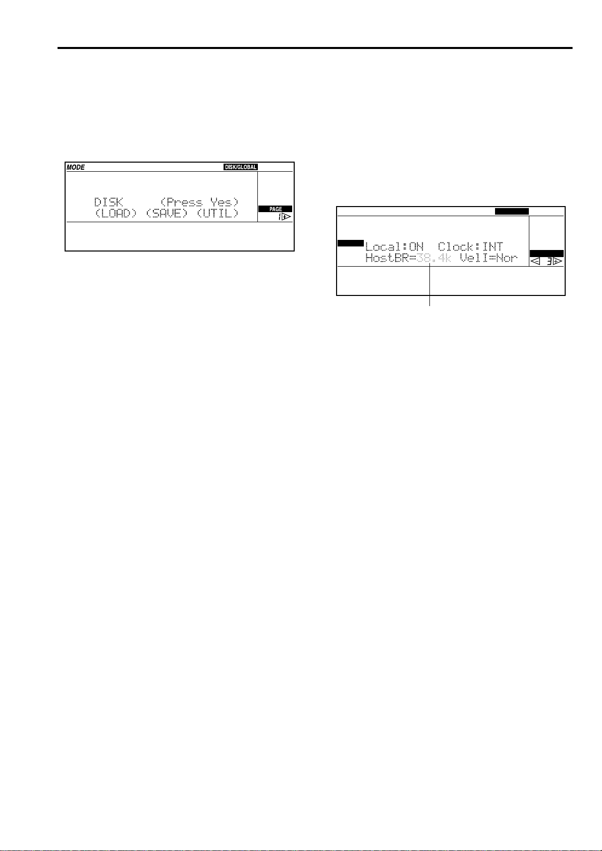
Getting Started • Operative modes
Subpages
Some of the display pages allow you to select secondary pages, referred to as “subpages”. The subpages are
indicated by two round brackets ( ) which contain the
option. In the display shown below, the (LOAD),
(SAVE) and (UTIL) items access the relative subpages.
Use the CURSOR buttons to place the cursor on the
name of the desired page and press the ENTER/YES
button to access the selected subpage. To return from a
subpage to the higher page press the EXIT/NO button.
Programming a parameter
value
In order to modify the value of a parameter that
appears on the display, first of all you need to select
the value with the cursor. The cursor is indicated by
the flashing of the value or the text line selected. Move
the cursor in the display with the CURSOR buttons
and modify the value with the TEMPO/VALUE. buttons.
MODE
VALUE
Cursor
DISK/GLOBAL
PAGE
19
Page 28
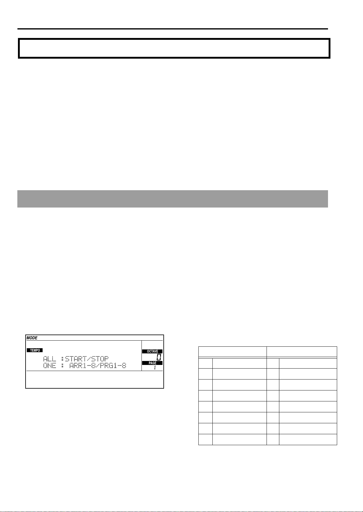
Getting Started • Tutorial
4. Tutorial
This chapter is a practical guide to the use of the i40M
that illustrates some real examples. All you need to do
is follow these simple “lessons” and you will master
the main functions of the instrument in a very short
time.
Whilst using the instrument you may find yourselves
in trouble, without knowing how to get out of a particular situation or edit page you have accessed by mistake. Remember that:
• EXIT/NO returns to the main pages of the vari-
ous operative modes;
Demo
Listening to the Demo
The Demo is a selection of demonstrative songs contained in memory that cannot be erased (ROM). Let’s
listen to them to get an idea of the sound capabilities
of the instrument.
• START/STOP stops the accompaniments;
• RESET interrupts all the notes you are playing;
• turn the instrument off and on again to return to
the initial situation (songs and backing
sequences in memory are lost).
The names of the programs, styles and arrangements
that appear in the next pages may be slightly different
from those of the actual instrument—Don’t worry,
they are only examples!
2 Press START/STOP again to stop the demo.
To listen to a single demo
1 Select the demo with the buttons of the PRO-
GRAM/ARRANG section.
Entering the Demo mode
●Press the ARR.PLAY and B.SEQ (DEMO) buttons
together
The “Demo” page will appear.
To listen to all the demo
1 Press START/STOP.
The demo songs will playback one after the other.
If you wish to select a demo from number 1 to 8,
press the PROGRAM/ARRANG button to light up
the ARRANG led and then a button [1]–[8] of the
NUMBER section. If you wish to select a demo
from number 9 to number 16 press the PROGRAM/ARRANG button to light up the PROGRAM led and then a button [1]–[8] of the
NUMBER section.
ARRANGEMENT NO. PROGRAM NO.
1 Synth World 1 Classic Piano
2 Jazz 2 Contemp. Piano
3 Latin 3 Bolero
4 Rock 4 Dance
5 Gospel 5 Jungle
6 Quick Step 6 Garage
7 German Polka 7 Progressive
8 Valzer 8 Modern Beat
2 Press START/STOP again to stop the demo.
20
Page 29
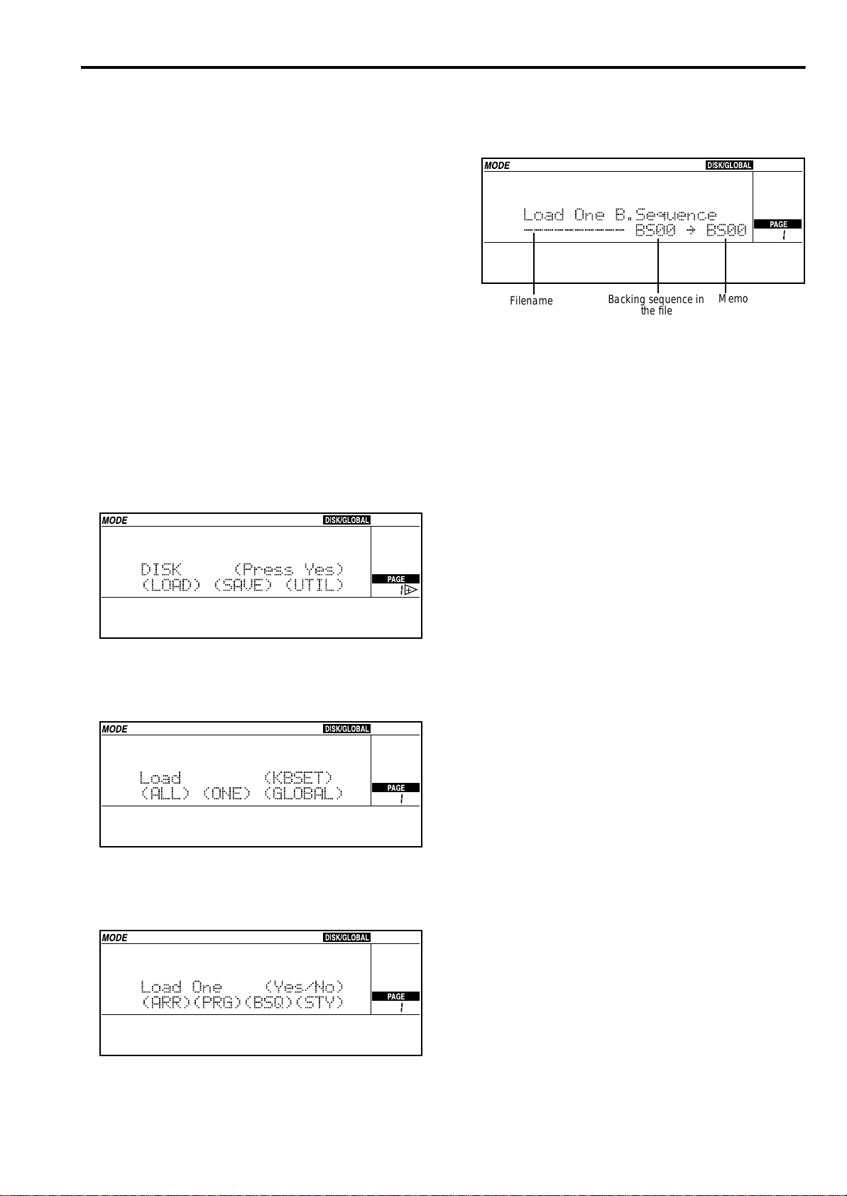
Getting Started• Tutorial
To exit the Demo mode
●Press EXIT/NO or one of the buttons of the
MODE section.
By pressing EXIT/NO you go back to the Arrangement Play mode. by pressing a button of the MODE
section you go to the selected mode.
The Backing Sequence demo
The Accessory Disk supplied with the instrument contains the demonstration backing sequences. Reading
them on disk will help us understand how the backing
sequences work.
1 Insert the Accessory Disk into the disk drive.
2 Press DISK/GLOBAL to enter the Disk/Global
mode.
The DISK/GLOBAL led will light up. The DISK/
GLOBAL indicator will appear on the display.
5 Move the cursor on (BSQ), and press ENTER/
YES view the files contained in the disk.
Filename
The display shows the name of the file which contains the backing sequence to be loaded, the backing sequence number and the location number in
the memory where to load it.
Backing sequence in
the file
Memory loca-
tion
6 Use the TEMPO/VALUE buttons to select the file
you wish to load.
7 Select the backing sequence you wish to load
and the memory location where to load it.
3 While the cursor is on (LOAD), press ENTER/YES
to enter the “Load” subpage.
Load (KBSET)
(ALL) (ONE) (GLOBAL)
4 Move to cursor on (ONE), and press ENTER/YES
to enter the “Load One” subpage.
In the figure the backing sequence 00 will be loaded
in location 00. Each file can contain up to ten backing sequences and there are ten backing sequence
locations in the memory, numbered from 00 to 09.
To select a different backing sequence or load it in a
different location, move the cursor to the “BS00”
parameters and select different numbers and locations.
We do not need to make any change in the example, since we want to load the backing sequence 00
in location 00.
8 Press ENTER/YES to load the selected backing
sequence.
9 When “Completed” appears on the display,
press B.SEQ to enter the Backing Sequence
mode.
The B.SEQ button led will light up. The BACKING
SEQUENCE indicator will appear on the display.
0 Use the CURSOR buttons to move the cursor to
the back sequence name. Use the TEMPO/
VALUE buttons to select the backing sequence
you wish to listen to.
We do not need to make any change in the example, since the backing sequence 00 is already
selected when switching to the Backing Sequence
mode.
1 Press START/STOP to start the playback.
21
Page 30
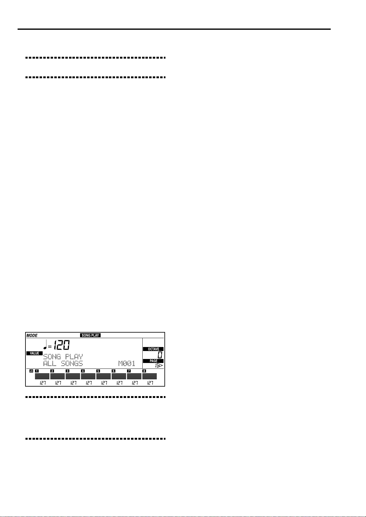
Getting Started • Tutorial
0 Press START/STOP again to stop the playback.
Note: When the instrument is turned off, the backing
sequences in memory will be canceled.
Listening to the songs
The songs are musical pieces with sixteen tracks available in the form of Standard MIDI Files (SMF). The
i40M is able to playback SMF format 0 without having
to load them in memory, and SMF format 1 after a
short loading.
If the SMF is in Solton, M-live (Midisoft), Tune1000 or
compatible (Edirol, GMX, KAR, HitBit, XF) format and
contains lyrics, the lyrics are viewed in time with the
music.
If the SMF is in Solton, M-live (Midisoft), or GMX format and contains chord abbreviations, the abbreviations are viewed in time with the music.
You can playback a single song, or create a list to playback with just one command (for example with the
JukeBox function).
To listen to a song
1 Inser t the disk containing the song into the disk
drive.
2 Press SONG PLAY to enter the Song Play mode
(Lyrics 1 mode).
The SONG PLAY led and the REC/WRITE/LYRICS led will light up.
If the file has a number between 1 and 8, press the
PROGRAM/ARRANG button to light up the
ARRANG led, then press the BANK [A] button and
a NUMBER button from [1] to [8].
If the file has a number between 9 and 16, press the
PROGRAM/ARRANG button to light up the
ARRANG led, then press the BANK [B] button and
a NUMBER button from [1] to [8].
If the file has a number between 17 and 24, press
the PROGRAM/ARRANG button to light up the
ARRANG led, then press the BANK [USER] button
and a NUMBER button from [1] to [8].
4 After selecting the song, press START/STOP.
If the selected song is in M-live (MidiSoft), Solton,
or Tune1000 or compatible (Edirol, GMX, KAR,
HitBit, XF) format and contains lyrics, the lyrics
appear on the display in time with the music. If not,
the display shows the standard information.
If the song is format 1, the red START/STOP led
will flash for a few seconds, while the data is being
loaded from the disk. When loading ends, playback
will begin. If some backing sequences or songs are
already loaded in the Song Edit mode, a message
will appear asking you if it is OK to erase this data.
If you don’t mind losing the data in the memory,
press ENTER/YES to start playback.
If you wish to retain the data, press EXIT/NO to
cancel loading. Switch to the Disk/Global mode
and save the song and backing sequences on
another disk (see page 131). Then go back to the
Song Play mode and repeat the operation.
●If the song is in Tune1000 or compatible (Edirol,
GMX, KAR, HitBit, XF) format, press REC/
WRITE/LYRICS to switch to the Lyrics 2 mode.
Note: In the Song Play mode the REC/WRITE/LYRICS led will automatically light up to indicate that you
are in the Lyrics 1 mode and that the lyrics of the song
can be viewed. If the led is off, you are in Play mode
(standard executive information).
3 Select the song with the TEMPO/VALUE buttons.
You can also select the song by entering its position
number on the disk.
22
If the song is in a different format, pressing REC/
WRITE/LYRICS will display the executive information page (Play mode).
With the Tune1000 and compatible (Edirol, GMX,
KAR, HitBit, XF) format there are two ways to view
the lyrics:
• Lyrics 1 (the whole line will appear at once on
the display);
• Lyrics 2 (the words appear one at a time, in time
with the music). Press REC/WRITE/LYRICS to
switch to the Lyrics 2 mode.
●Press REC/WRITE/LYRICS to change the viewing
mode from the lyrics (Lyrics modes) to the standard executive information (Play mode).
The REC/WRITE/LYRICS led will go off.
●Press REC/WRITE/LYRICS again to view the lyr-
ics (Lyrics 1 mode).
Page 31

Getting Started• Tutorial
The REC/WRITE/LYRICS led will light up.
5 To stop the song, press START/STOP.
Listening to all the song on a disk
1 Inser t the disk containing the songs in SMF for-
mat 0 or 1.
2 Press SONG PLAY to enter the Song Play mode.
The SONG PLAY and REC/WRITE/LYRICS leds
will light up.
3 If the name of a song appears on the display,
press EXIT/NO to display “ALL SONGS”.
●If the played song is in Tune1000 or compatible
(Edirol, GMX, KAR, HitBit, XF) format, press
REC/WRITE/LYRICS to switch to the Lyrics 2
mode.
●Press REC/WRITE/LYRICS to change the viewing
mode from the lyrics (Lyrics modes) to the standard executive information (Play mode).
●Press REC/WRITE/LYRICS again to view the lyr-
ics (Lyrics 1 mode).
5 Press START/STOP to stop the playback.
JukeBox
The JukeBox allows you to create a list of songs to
be played back with just one command, choosing
among the songs contained on the disk.
1 Inser t the disk containing the songs in SMF for-
mat 0 or 1 into the disk drive.
2 Press SONG PLAY to enter the Song Play mode.
The SONG PLAY led will light up.
Now all the songs contained in the disk are
selected. Press EXIT/NO to go back to ALL SONG
after selecting a single song.
4 Press START/STOP to start the playback of all
songs.
The songs in SMF format 0 are played back at once.
If the song is in M-live (MidiSoft), Solton, or
T une1000 or compatible (Edir ol, GMX, KAR, HitBit,
XF) format and contains lyrics, the lyrics appear on
the display in time with the music. If not, the display shows the standard information.
If the song is in M-live (MidiSoft), Solton, or GMX
format and contains chord abbreviations, the
abbreviations appear on the display in time with
the music.
The songs in SMF format 1 must be loaded in memory first, then after a few seconds wait they are
played back. If some backing sequences or songs
are already loaded in the Song Edit mode, a message will appear asking you if it is OK to erase this
data. If you don’t mind losing the data in memory,
press ENTER/YES to start playback.
3 Choose the first song with the TEMPO/VALUE
buttons.
4 Press ENTER/YES to insert the song in the list.
The name of the song, alongside its position number on the list, will appear on the display. Number
1 will appear after you have inserted the first song.
Position on the list
If you wish to retain the data, press EXIT/NO to
cancel loading. Switch to the Disk/Global mode
and save the song and backing sequences in
another disk. Then go back to the Song Play mode
and repeat the operation.
Selected song
23
Page 32

Getting Started • Tutorial
5 Choose the second song to be added in the list
with the TEMPO/VALUE buttons.
6 Press ENTER/YES to confirm the second song on
the list.
7 Add other songs to the list by following steps 5-
6.
8 Once the list is complete, press START/STOP to
play back all the selected songs.
The songs in SMF format 0 are played back at once.
If the song is in M-live (MidiSoft), Solton, or
T une1000 or compatible (Edir ol, GMX, KAR, HitBit,
XF format and contains lyrics, the lyrics appear on
the display in time with the music. If not, the display shows the standard information.
If the song is in M-live (MidiSoft), Solton, or GMX
format and contains chord abbreviations, the
abbreviations appear on the display in time with
the music.
The songs in SMF format 1 must be loaded in memory first, then after a few seconds wait they are
played back. If some backing sequences or a song
are already contained in the Song Edit mode, a
message will appear asking you if it is OK to erase
this data. If you don’t mind losing the data in memory, press ENTER/YES to start playback.
If you wish to retain the data, press EXIT/NO to
cancel loading. Switch to the Disk/Global mode
and save the song and backing sequences on
another disk. Then go back to the Song Play mode
and repeat the operation.
9 Press START/STOP to stop playback.
0 Press START/STOP again to re-start playback.
A Press EXIT/NO to exit the JukeBox mode.
24
Page 33

The arrangements
Getting Started• Tutorial
What are styles and
arrangements
The i40M features an automatic accompaniment system based on styles and arrangements. Playing with
this system is just as if you had a real band backing
you with six instruments: three harmonic instruments,
bass, drums and a percussion set.
The styles provide the musical structure of the accompaniment, while the arrangements provide the
sounds, effect and some general parameters. Generally
speaking, the style is the “music style”, while the
arrangement is its “instrumentation”.
During the playback you can select the arrangements
and play live with the three real time tracks Upper 1,
Upper 2 and Lower (two tracks at a time: Upper 2 and
Lower exclude one other).
How to program the MIDI
The i40M need to receive the chords from a controller
(MIDI keyboard, digital piano, MIDI accordion, MIDI
guitar etc.). Then the arranger will transform the
chords in accompaniment patterns according to the
selected arrangement and style.
The chords must get at least to one of these special
MIDI channels: Global, Chord 1, and Chord 2. For
information on the connection of the MIDI controller
see the detailed description contained in “MIDI” on
page 44.
1 Press ARR. PLAY to enter the Arrangement Play
mode.
The ARR.PLAY led will light up. The ARR.PLAY
indicator will appear on the display.
2 Press the PROGRAM/ARRANG button to light
up the ARRANG led.
3 Press one of the BANK [A], [B] or [USER] but-
tons.
4 Enter a two-digit number between 11 and 88
using the buttons of the NUMBER section.
If the arrangement is contained in the same bank as
the selected arrangement, you only need to enter a
two-digit number, without pressing a BANK button.
Arrangement Preview. In the Arrangement Play
mode the Arrangement Preview function allows
you to view the arrangement name on the display
before selecting it.
Press a BANK button, use a NUMBER button to
select the tens – if necessary – then select the
arrangement with the TEMPO/VALUE buttons
and confirm with ENTER/YES.
Once the selection has been completed, the name of
the selected arrangement will appear on the display:
Tempo of selected arrangement
The KEYBOARD MODE section of the control panel
works only if the controller is connected through the
Global channel. This channel is generally used when
connecting a master keyboard. For more information
on the Global channel see “The Global channel” on
page 45.
Selecting an arrangement
The i40M includes 192 arrangements divided into
three banks of 64 each (64 in bank A, 64 in bank B, and
64 programmable in bank USER).
The arrangement families are listed in the top section
of the control panel. The complete list of the arrangements is contained at the end of this guide (see
page 205).
Selected arrangement
The style (and the accompaniment patterns)
changes and:
• if the SINGLE TOUCH led is on, also the real
time programs (Upper 1, Upper 2, and Lower
tracks) change;
• if the TEMPO led is off, also the metronome
time changes.
25
Page 34

Getting Started • Tutorial
Note: The arrangement can memorize the status of
the control buttons. Therefore when changing the
arrangement, you can also select one of the two fills,
one of the two intros or one of the four variations.
Starting the accompaniment
After selecting an arrangement, you can start the automatic accompaniment.
1 Press RESET/INS to reset the values.
RESET erases the chords that are still in memory.
2 Press START/STOP.
Rhythm play will start. The START/STOP red led
will light up on the first beat, the green led on the
other beats, according to the time signature of the
style.
3 Play a progression of chords.
The keyboard area and the way in which chords ar e
detected will depend on the type of connection, on
the split point, on the status of the CHORD SCANNING section, and on the “ChordRecog (Chord
recognition mode)” parameter of the Disk/Global
mode (see page 147).
Once the chord has been detected, the rhythm will
be joined by the bass and the other accompaniment
tracks that play following the detected chords.
If the MEMORY-CHORD button led is on, the
chords will remain in memory also after releasing
the notes.
The chord name is shown on the display:
Recognized chord
4 Continue playing the chords and play the mel-
ody.
5 Press START/STOP to stop the accompaniment.
Synchro start e stop
You can make the accompaniment start or stop without pressing START/STOP.
When the i40M is connected with a MIDI key-
board through the special Global channel,
• if the CHORD SCANNING is LOWER, the
chords played with the left hand below the split
point will be detected;
• if the CHORD SCANNING is UPPER or FULL,
the chords played above the split point or with
two hands on the entire keyboard will be
detected.
Note: If the option assigned to the “ChordRecog
(Chord recognition mode)” parameter is “Fingered
1”, you only need to play a note to detect a major
chord.
When the i40M is connected with a MIDI controller
through channels other than Global (for example,
when a MIDI accordion is connected), chords must
come through the Chord 1 and Chord 2 channels
with no extension limits.
The MIDI Setup (see page 136) selected when connecting the controller will always create the suitable condition to send the chords in the correct way
through the appropriate channels.
1 With the accompaniment stopped, light up the
SYNCHRO-START led.
The Synchro Start makes the accompaniment start
when the notes for the chord recognition chords ar e
played.
2 Play a chord in the chord recognition area to
start the accompaniment.
3 Light up the SYNCHRO-STOP led.
The Synchro Start makes the accompaniment stop
when the notes for the chord recognition chords ar e
released.
4 Release the chord recognition notes to stop the
accompaniment.
The accompaniment stops at once.
5 Play a chord again in the chord recognition
area to restart the accompaniment.
6 Turn off the SYNCHRO-STOP led.
If the SYNCHRO-STOP led is off and the MEMORY-CHORD led is on, the accompaniment will
continue playing also when the chord recognition
notes are released.
26
Page 35

Getting Started• Tutorial
7 Continue playing, then press START/STOP to
stop the accompaniment.
Fill
The fill is an interlude that breaks the rhythm continuity. Each style of the i40M has two different fillins.
1 Start the automatic accompaniment (with
START/STOP or SYNCHRO-START + played
notes).
2 Whilst playing press one of the FILL [1] or [2]
keys.
A fill-in will be played. When the fill finishes, a different variation may be selected (see “Page 5:
Ensemble/Variation change” in the Arrangement
Play mode).
3 Press START/STOP to stop the accompaniment.
1 Start the accompaniment (with START/STOP,
INTRO/ENDING + START/STOP, or SYNCHROSTART + played notes).
2 Press one button in the VARIATION section.
The led of the selected variation will start flashing.
At the end of the measure the pattern will change.
The led of the new variation will stay lit.
3 Press one of the FILL buttons and straight away
afterwards one button in the VARIATION section.
The fill-in will play. The led of the variation that is
going to play at the end of the fill-in will flash. At
the end of the fill-in the new variation will play.
4 Press START/STOP or INTRO/ENDING to stop
the accompaniment.
Note: On “Page 5: Ensemble/Variation change” in
the Arrangement Play mode, you can connect each
FILL button to a variation that will be selected automatically after the fill-in has finished.
Intro/ending
“Intro” means introduction, “ending” means end.
Each style has two intros and two endings, which are
selected by one of the two buttons in the INTRO/
ENDING section.
1 With the accompaniment stopped, press one of
the INTRO/ENDING [1] or [2] buttons.
2 Start the automatic accompaniment with ST ART/
STOP (or SYNCHRO-START + played notes).
The introduction will be played, then the normal
accompaniment pattern will begin (“Variation”).
Note: The Intro 1 can play different chords, while the
Intro 2 only plays with the recognized chord.
3 Play normally, then press one of the INTRO/
ENDING [1] or [2] buttons.
The ending will be played and the accompaniment
will stop.
Note: The Ending 1 can play different chords, while
the Ending 2 only plays with the recognized chord.
All the tracks, at once!
1 With the SYNCHRO-START led off, play a chord
in the chord recognition area.
2 Press START/STOP (or INTRO/ENDING +
START/STOP) to start the accompaniment.
The accompaniment tracks (Drum, Percussion,
Bass, Acc1, Acc2, Acc3) will start playing.
3 Press START/STOP or INTRO/ENDING to stop
the accompaniment.
Fade in/out
1 With the accompaniment stopped, play a chord
in the chord recognition area, then press FADE
IN/OUT to start the accompaniment.
The accompaniment will start. The volume of the
accompaniment tracks and the real time tracks will
be set at zero, and will gradually increase to full.
2 While the accompaniment is playing, press
FADE IN/OUT to stop the accompaniment.
Variations
Variations are different versions of the same style Each
style has four variations.
The volume of the accompaniment tracks and the
real time tracks will gradually decrease to zero. At
the end, the accompaniment will stop and the volume will come back to full.
27
Page 36

Getting Started • Tutorial
Varying the tempo
●With the accompaniment stopped, use the
TEMPO/VALUE buttons to vary the tempo.
In order for these controls to work as tempo controls, the TEMPO indication must appear on the
left-hand side of the display.
There is an easier way to vary the tempo, which is
as follows:
1 Set (beat) the tempo on the TAP TEMPO button.
The tempo shown on the display will change
according to the tempo beaten.
2 Start the accompaniment.
3 Vary the tempo with the TEMPO/VALUE buttons.
4 Stop the accompaniment with START/STOP or
INTRO/ENDING.
28
Page 37

The real time tracks (Upper 1, Upper 2, Lower)
Getting Started• Tutorial
What are the real time tracks?
The real time tracks (Upper 1, Upper 2 e Lower) can be
used to play “live” over the automatic accompaniment
tracks.
You can have two tracks at the same time, since Upper
2 and Lower exclude one other.
If the real time tracks are managed through the special
Global channel, the split point – and the KEYBOARD
MODE section in general – are taken into consideration. In this case:
• if the Keyboar d Mode is SPLIT, the Upper tracks
can play above the split point and the Lower
track below the split point;
• if the Keyboard Mode is FULL UPPER, the
Upper tracks can play on the entire extension.
Note: If notes are received from channels other than
Global, the tracks will ignore the split point. If the
channel assigned to the track coincides with Global,
Global has the priority and the split point is taken into
consideration. For the assignation of the MIDI channels to the tracks and Global, see page 139.
3 Press FULL UPPER to play the Upper 1 and/or
Upper 2 tracks on the entire keyboard.
Use the buttons in the KEYBOARD ASSIGN section to activate or deactivate the tracks.
4 Press SPLIT to split the keyboard in two parts
again.
Activating and deactivating the
real time tracks
The real time tracks can be activated or deactivated in
two ways:
• using the buttons in the KEYBOARD ASSIGN
section (the led lights up when the track is playing);
• using the UP1 and UP2/LOW buttons in the
PROGRAM/VOLUME section (press two buttons together to mute the track; press one button
to activate it again).
Note: The Upper 2 and Lower tracks exclude one other.
When UPPER 2 is selected, LOWER is automatically deactivated, and vice versa.
Assigning the real time tracks
to the keyboard
If the i40M is connected to a MIDI keyboard through
the special Global channel (see pages 45 and 47), you
can assign the real time tracks to the keyboard areas
with the buttons in the KEYBOARD MODE section.
1 Press M.DRUM to play the dr um kit on the key-
board.
2 Press SPLIT to split the keyboard in two parts.
The Upper 1 and/or Upper 2 tracks can play on the
right-hand side of the split point, while the Lower
track can play on its left-hand side.
Use the buttons in the KEYBOARD ASSIGN section to activate or deactivate the tracks.
Note: The Upper 2 and Lower tracks exclude one
other.
1 Light up the UPPER 1 led (KEYBOARD ASSIGN
section) to activate the Upper 1 track.
Press the button to select the Upper 1 track.
2 Light up the UPPER 2 led (KEYBOARD ASSIGN
section) to activate the Upper 2 track.
Press the button to select the Upper 2 track. The
Lower track is deactivated.
3 Light up the SPLIT led (KEYBOARD MODE sec-
tion) to split the keyboard, then light up the
LOWER led (KEYBOARD ASSIGN section) to activate the Lower track.
Press the button to select the Lower track. The
Upper 2 track is deactivated.
Note: The Lower track can only be activated when
the KEYBOARD MODE is SPLIT.
29
Page 38

Getting Started • Tutorial
Blocking the programs of the
real time tracks
When you change an arrangement, you usually
change also the programs assigned to the real time
tracks. If you wish to change the accompaniment, but
not the programs of the real time tracks, turn off the
SINGLE TOUCH button led. With the SINGLE
TOUCH led on, the arrangement will also change the
programs and the volume of the real time tracks.
Changing the sounds of the
real time tracks
You can assign one of the i40M programs to each real
time track.
1 If the i40M is connected to a keyboard, press
the SPLIT button to split the keyboard in two
parts.
2 Select the Upper 1 track by pressing one of the
UPP1 buttons in the PROGRAM/VOLUME section.
The abbreviation “UP1” will appear on the second
text line of the display, followed by the bank number, name and number of the program assigned to
the Upper 1 track.
loaded from disk or directly programmed by the
user.
5 Using the buttons of the NUMBER section select
a two-digit number between 11 and 88.
To select a drum kit, press the [F/USER/DRUM]
button twice, until the abbreviation “Dr” appears
on the display.
If the program you wish to select is in the same
bank as the selected program, you only need to
select the two-digit number, without pressing a
BANK button.
After selecting the bank and indicating a two-digit
number, the program will be selected and assigned
to the Upper 1 track.
Program Preview. In the Arrangement Play mode
you can use the Program Preview function to view
the name of the program on the display before
selecting it.
Press a BANK button, use a NUMBER button to
select the tens – if necessary – then select the program with the TEMPO/VALUE buttons and confirm with ENTER/YES.
6 Select the Upper 2 track by pressing one of the
LOW/UPP2 buttons in the PROGRAM/VOLUME
section and activating UPPER 2 in the KEYBOARD ASSIGN section.
If active, the Lower track will be deactivated. The
abbreviation “UP2” will appear on the display, followed by the bank number, name and number of
the program assigned to the Upper 2 track.
Bank Number
Name
3 Press the PROGRAM/ARRANG button to light
up the PROGRAM led.
4 Press one of the BANK [A], [B], [C], [D], [E],
[F(USER/DRUM)] buttons.
The A and B banks contain the 128 programs of the
General MIDI standard. The A bank contains the
first 64 programs, the B bank contains the other 64
programs. The C and D banks contain programs
that are more or less organized as in the General
MIDI banks, however there are some differences.
The E bank contains layered programs and fantasia
sounds, while the F(USER) bank contains programs
7 Select a program with the procedure illustrated
for the Upper 1 track.
8 Select the Lower track, by pressing one of the
LOW/UPP2 buttons in the PROGRAM/VOLUME
section and activating LOWER in the KEYBOARD
ASSIGN section.
If active, the Upper 2 track will be deactivated. The
abbreviation “LOW” will appear on the display,
followed by the bank number , name and number of
the program assigned to the Lower 2 track.
9 Select a program with the procedure illustrated
for the Upper 1 track.
0 Select the Upper 1 track again (press one of the
UPP1 buttons in the VOLUME section).
The abbreviation “UP1” will appear on the display.
All the next selections of programs will be assigned
to the Upper 1 track.
30
Page 39

Getting Started• Tutorial
Transposition
You can change the pitch of the real time tracks with
the semitone transposition.
Note: If the accompaniment is playing during the modification, the transposition will enter at the beginning of the
next measure.
●To lower the real time track pitch by one or
more semitones press the TRANSPOSE [ ] button
once or more.
The sound pitch will be lowered by a semitone
each time the button is pressed.
●To raise the real time track pitch by one or more
semitones press the TRANSPOSE [ ] button
once ore more.
The sound pitch will be raised by a semitone each
time the button is pressed.
●To cancel the transposition press both TRANS-
POSE buttons together.
1 Press the BANK button in the KEYBOARD SET
section a few times, to turn on the C bank led.
Each time you press the BANK button, one of the
banks is selected in cyclic mode:
A ⇒ B ⇒ C ⇒ A…
2 Press button 1 of the KEYBOARD SET section.
Keyboard Set 1 of the C bank will be selected. The
programs of the real time tracks will change and
the status of Chord Scanning, Keyboard Assign,
Keyboard Mode, the effects, etc. could change, too
(depending on the data saved in the Keyboard Set).
Recording a Keyboard Set
It is possible to record the status of the real time tracks,
the effect and the VOCAL/GUITAR section in a Keyboard Set. Let’s try to record the current status in Keyboard Set 5 of the B bank.
1 Press REC/WRITE/LYRICS and press one of the
buttons in the KEYBOARD SET section.
Selecting a Keyboard Set
By selecting a Keyboard Set in the Arrangement Play
mode, you can select the programs of the real time
tracks, the Keyboard Mode, the Keyboard Assign, the
Chord Scanning, the effects, as well as other characteristics that would otherwise have to be programmed
one at a time.
In Arrangement Play and Song Play, the Keyboard Sets
also recall the settings of the VOCAL/GUITAR section.
There are three banks (A, B, C) with five Keyboar d Sets
each (1, 2, 3, 4, 5). Let’s try to select Keyboard Set 1 of
the C bank.
The Write Keyboard Set page will appear.
2 Press a few times the BANK button in the KEY-
BOARD SET section to light up the B led.
3 Press button 5 in the KEYBOARD SET section.
4 Press ENTER/YES twice to save (or EXIT/NO to
cancel).
The status of the real time tracks, the effects and the
VOCAL/GUITAR section is saved in Keyboard Set
5 of the B bank. You can save the Keyboard Sets
with the Save functions in the Disk/Global mode
(see page 131).
Note: To retrieve the original Keyboard Sets, load the
Keyboard Set contained in the Accessory Disk supplied.
31
Page 40

Getting Started • Tutorial
The backing sequences
What are the backing
sequences?
The backing sequences are musical pieces created by
playing the real time tracks and the arrangement
accompaniment.
The creation of a new song in the Backing Sequence
mode consists in recording a standard playing with
the arrangements, just like if you were playing normally in the Arrangement Play mode.
Apart from the tracks available in the Arrangement
Play mode, the Backing Sequence mode contains other
eight tracks (Extra T racks) wher e you can record fr eely.
The backing sequences can be saved on disk as backing sequences or Standard MIDI File (see “Page 18:
SMF converter” on page 105).
Recording the Backing
Sequences
2 If the i40M is connected to a keyboard or to
another controller, program it to transmit over
the special Global channel.
Note: The backing sequence must receive the real
time tracks over the Global channel and the chords
over the Global and/or the Chord 1 and Chord 2
channels.
3 Press B.SEQ to enter the Backing Sequence
mode.
The B.SEQ led will light up. The following display
will appear.
Tempo
Measure number
With the i40M you can create new songs exploiting the
wealth of material in the automatic accompaniment.
This type of songs is known as Backing Sequence.
Note: While recording, you cannot select some of the
buttons, e.g. the Keyboard Sets.
1 If the i40M is connected to a MIDI accordion,
switch to the Disk/Global mode and select the
MIDI Setup “Accordion 1”.
See “Connecting the i40M to a MIDI accordion” on
page 49. “Accordion 1” allows you to transmit the
right hand over the special Global channel and the
chords over the Chord 1 and Chord 2 channels.
Note: The backing sequence must receive the real
time tracks over the Global channel and the chords
over the Global and/or the Chord 1 and Chord 2
channels.
Arrangement
Backing Sequence name
4 Select the backing sequence you wish to record
with the TEMPO/VALUE buttons.
For this example, let’s select BSQ3. (If BSQ3 is
recorded, select another backing sequence).
5 Select an arrangement with the buttons of the
PROGRAM/ARRANG section.
Press the PROGRAM/ARRANG button to light up
the ARRANG led, then one of the BANK [A], [B] or
[USER] buttons to select the bank. Finally, press
two NUMBER button in sequence to choose a twodigit number between 11 and 88.
6 If necessary, change the split point, the Key-
board Mode, the Keyboard Assign and the
Chord Scanning.
Split point: hold down SPLIT POINT and play the
note that you wish to be the new split point. Key-
board Mode: use the buttons in the KEYBOARD
MODE section. Keyboard Assign: use the buttons
of the KEYBOARD ASSIGN section. Chord Scan-
ning: use the buttons of the CHORD SCANNING
section.
32
Page 41

Getting Started• Tutorial
7 Press REC/WRITE/LYRICS to enter the recording
mode.
The REC/WRITE/LYRICS led will light up and the
recording page will appear. If the “ATr” (arrangement tracks) tracks are selected, you can record
both the real time and the accompaniment tracks in
real time.
Tempo
Real time track
Selected track(s)
Control track
Quantize value
Chord track
Metronome
8 Press START/STOP (or one of the INTRO/END-
ING buttons + START/STOP) to start the accompaniment.
After a two-measure pre-count, recording will
begin and the accompaniment will start playing.
non-copy protected and must have space enough to
contain the new data.
2 Press Disk/Global to enter the Disk/Global
mode.
The following display will appear:
3 If you have inser ted a blank disk, you need to
format it.
1. Move the cursor to (UTIL) using the CURSOR
buttons. Press ENTER/YES to enter the “Utilities” subpage.
2. Move the cursor to (FORMAT) using the CURSOR buttons. Press ENTER/YES to enter the
“Format disk” subpage.
3. Press ENTER/YES to start formatting. After a
couple of minutes the disk will be ready to use.
9 You can now play freely. During the recording
you can use the FILL, VARIATION, ENDING buttons freely.
0 Press START/STOP (or one of the INTRO/END-
ING buttons) to stop the accompaniment and
the recording.
The recording will stop and the REC/WRITE/LYRICS led will go off. The sequencer will go back to
measure 001.
A Press START/STOP to listen to the song that you
have just recorded.
Saving the Backing Sequences
on disk
The backing sequences contained in memory will be
lost when you turn the instrument off, therefore you
need to save them on disk. The following procedure
allows you to save all the back sequences contained in
memory (max 10) in a new file.
4. Press EXIT/NO to go back to the main page in
the Disk/Global mode.
4 Move the cursor to (SA VE) and press the ENTER/
YES button to enter the “Save” subpage.
5 Move the cursor to (BSQ) and press the ENTER/
YES button.
The following display appears:
Note: If you have used arrangements and programs
from the USER bank, choose (ALL) instead of (BSQ).
This operation will save the entire contents on memory, including the USER arrangements and the USER
programs used by the backing sequence.
1 Insert an empty disk into the disk drive.
The i40M uses 3.5” 2DD/HD (double density or
high density) disks. The disk must be formatted in
MS-DOS® format, compatible with Windows™,
Macintosh® and other systems. The disk must be
6 Assign a new filename.
1. Select the character you wish to change with the
CURSOR buttons.
33
Page 42

Getting Started • Tutorial
2. Change the character using the TEMPO/
VALUE buttons.
3. Press INS to insert a new character and DEL to
delete the character indicated by the cursor.
7 Press ENTER/YES to save the file on disk.
To cancel the operation press EXIT/NO.
8 When the message “Completed” appears on
the display, press the B.SEQ button to go back
to the Backing Sequence operative mode.
Deleting the Backing
Sequences
If you don’t mind losing the backing sequence and
you need space in memory, you can delete it. The
backing sequences use up space in memory, taking it
away from other data (e.g. songs in Song Edit, other
backing sequences).
1 Press B.SEQ to enter the Backing Sequence
mode.
2 Press PAGE [+] repeatedly to get to “Page 3:
Erase Backing Sequence” in the Backing
Sequence mode.
3 Press ENTER/YES twice to delete the backing
sequence from memory.
4 Press EXIT/NO to go back to the first page of
the Backing Sequence mode.
The Songs
What are the Songs?
The songs are musical pieces with sixteen tracks that
can be saved on disk in the form of Standard MIDI File
(SMF). There are two operative modes dedicated to the
songs: the first one is used to read the songs live (Song
Play) and the second one is used to create new songs
or edit the existing songs (Song Edit).
Unlike the backing sequences, the songs are made up
of completely free tracks that cannot be created with
the arrangements. You can however convert a backing
sequence into a standard song (see “Page 18: SMF converter” on page 105).
The i40M is compatible with most of the songs found
on the market. You can convert songs created with the
computer sequencer into songs that can be read by the
i40M, and vice versa.
1 Press SONG EDIT to enter the Song Edit mode.
2 Press PAGE [+] to go to Page 2.
Track
Tempo mode
Recording mode
Quantize Metronome
Starting measure
Ending measure
Recording a song
In the Song Edit mode you can record a new song
freely and save it on disk as a Standard MIDI File
(SMF).
34
Page 43

Getting Started• Tutorial
3 Whilst on Page 2, press REC/WRITE/LYRICS to
enter the recording mode.
4 Select the track you wish to record with the but-
tons of the PROGRAM/VOLUME section. Use the
TRACK SELECT button to switch between the 1-8
and 9-16 tracks.
5 Program the MIDI controller to transmit over the
channel of the track you wish to record.
The tracks need to receive channeled information
and not over the special Global channel. Each track
of the song usually corresponds to a MIDI channel
with the same number as the track. For example,
track 1 usually corresponds to channel 1, track 2 to
channel 2 and son on.
Suggestion: if it is not possible to change the MIDI
channel used by the MIDI controller for transmission, follow this procedure:
1. Go to “Page 3: Track parameters” in the Song
Edit mode.
2. Modify the “Ch” parameter by assigning the
number of the MIDI channel used by the MIDI
controller for transmission.
8 Move the cursor to the Q parameter and select
a quantize value.
The quantize corrects the rhythmical mistakes
made during the recording. The quantize value is
expressed in musical values. Very high values can
deeply change the recording.
9 Move the cursor to the M parameter and acti-
vate or deactivate the metronome.
OFF means that the metronome is deactivated. ON
means that it is active both during the recording
and playback. REC means that it is active only during the recording.
0 Press START/STOP to start the recording.
Play freely.
A At the end press START/STOP to stop the record-
ing.
B Repeat the procedure with the other tracks.
Saving the Song as Standard
3. Go back to the recording page and record the
track.
4. Go to “Page 3: Track parameters” in the Song
Edit mode and assign the original MIDI channel
to the “Ch” parameter.
5. Select a different track and repeat the pr ocedur e,
assigning the MIDI channel used by the controller for transmission to the track you wish to
record.
6 Move the cursor to the Recording Mode param-
eter and select the recording mode.
You can select the OVRW option to delete the old
data and record the new data of the track.
Otherwise, in particular to record the drum track
one instrument a time, you can select OVDB, where
you can add new notes to existing notes.
The more complex AUTOP and MANP modes are
described on page 115
7 Move the cursor to the Tempo parameter and
program the metronome tempo.
MIDI File (SMF)
The songs and backing sequences contained in memory will be lost when you turn the instrument off,
therefore you need to save them on disk.
1 Insert a new disk into the disk drive.
The disk must be formatted, non copy-protected,
and must have space enough for the song you are
saving. To format the disk see “FORMAT (Format
disk)” on page 133.
2 If you are not already in the Song Edit mode,
press SONG EDIT.
3 Press repeatedly PAGE [+] to get to “Page 13:
Save” in the Song Edit mode.
If you select the AUT option, the tempo is the current one indicated by TEMPO/VALUE. If you
select the TEMPO-REC option, the tempo variations during the recording are recorded.
4 Assign a name to the song.
Move the cursor with the CURSOR buttons and
change the character indicated by the cursor using
the TEMPO/VALUE buttons.
35
Page 44

Getting Started • Tutorial
Be careful: If you are saving a file that was previ-
ously loaded from the disk, you need to change the
name of the file to avoid overwriting the existing file
on disk. A disk cannot contain two files with the same
name (in the same directory). A message will inform
you that you are overwriting an existing file.
5 Press ENTER/YES twice to confirm and the name
and save.
After pressing ENTER/YES the “Are you sure?”
will appear. Press ENTER/YES again to save the
Standard MIDI File on disk. When finished, the
message “Completed” will appear.
Editing Standard MIDI Files
(SMF)
A SMF can be modified, for example by adding a solo
or changing the program played by the track. Let’s try
to edit the song “iS-Lands” contained in the disk supplied with the instrument.
Loading and listening to the song
5 Press PAGE [+] to get to “Page 2: Playback”.
6 Press START/STOP to listen to the song.
The song will be played from beginning to end.
When it stops, the sequencer will go back to measure number 001. You can stop playback halfway
through the song by pressing START/STOP; in this
case, press RESET to get back to measure number
001.
Changing the sound of a track
Let’s replace the pan flute of the melody line with an
alto sax.
1 Press PAGE [+] repeatedly to get to “Page 4:
Event edit”.
1 Inser t the disk supplied with the instr ument into
the disk drive.
2 Press SONG EDIT to enter the Song Edit mode.
3 Select the file “ISLANDS” with the TEMPO/
VALUE buttons.
4 Press ENTER/YES twice to load the song.
The message “Now loading” will appear. When
finished, the message “Completed” will appear.
Selected track
2 Select track 6 (Tr06) using the TEMPO/VALUE
buttons.
The pan flute is to be found in track 6 (Tr06).
3 Press REC/WRITE/LYRICS, then START/STOP to
access Event Edit.
36
Page 45

Getting Started• Tutorial
4 Use the CURSOR buttons to move the cursor to
M001#00.
M001#00 indicates the measure number and the
step inside the measure (001 = measure 1, #00 =initial step of the measure).
5 Press TEMPO/V ALUE [UP/+] to select M001#01.
The #01 step is the first measure step that contains
performable data (for example, notes). There will
be a message showing the change of program on
the second line of the display text.
Message type
(“status”)
Bank
Select LSB
Program
Change
Program
6 Move the cursor to “075” using the CURSOR
buttons.
Deleting parts of a song
In this example we will delete the marimba accompaniment from the first four measures.
1 Press PAGE [+] repeatedly to get to “Page 7:
Edit”.
2 Move the cursor to (ERASE) using the CURSOR
buttons,
3 Press ENTER/YES.
Number “075” is the value of the MIDI Program
Change message. A program can be selected
through the combination of two Bank Select (usually abbreviated in BS MSB and BS LSB) and Program Change (usually abbreviated in PC). In the
i40M the message sequence BS MSB=000, BS
LSB=000 and PC=075 corresponds to program B24
(bank B, program 24) which is the pan flute.
7 Change the number to “065” using the TEMPO/
VALUE buttons.
The program change number “65” corresponds to
the B12 program (Alto Sax).
8 Press START/STOP to exit Event Edit.
9 Press EXIT/NO to get back to page 2 (Play).
0 Press START/STOP to listen to the edited song.
The melody will now be played by an alto sax.
4 Move the cursor to “Tr01”.
5 Press TEMPO/VALUE [UP/+] to select “Tr05”.
The marimba part is on track 5 (Tr05).
6 Moves the cursor to “001” located at the right
of the arrow.
As we want to delete the first four measures, measure 001 should be to the left of the arrow and measure 004 to the right of it.
7 Press TEMPO/V ALUE [UP/+] repeatedly to select
measure number “004”.
8 Press ENTER/YES twice.
The message “Completed” will appear on the display. The first four measures of the marimba part
will be deleted.
9 Press EXIT/NO to get to page 2 (Play).
0 Press START/STOP to listen to the song.
The marimba part will not play at the beginning of
the song anymore.
37
Page 46

Getting Started • Tutorial
Adding parts to a song
In this example, we shall add a counterpoint melody
to the song, recording it onto track 7 (Tr07).
1 If you are not already at page 2 (Play), press
EXIT/NO, or hold down SONG EDIT and press
ARRANGEMENT NUMBER [2].
(This is a shortcut to get directly to a page – see
page 18).
2 Press REC/WRITE/LYRICS.
3 Move the cursor to “Tr01” using the CURSOR
buttons.
with the same number as the track. For example,
track 1 usually corresponds to channel 1, track 2 to
channel 2 and son on.
6 Press PROGRAM/ARRANG to light up the PRO-
GRAM led, then press BANK [A], and finally
NUMBER [7] and [1].
This will assign the “A71 Strings” program to track
7 (Tr07).
7 Press START/STOP to start recording. Play the
new part.
After a two-measure precount, recording will
begin.
4 Press TEMPO/V ALUE [UP/+] repeatedly to select
“Tr07”.
5 Program the MIDI controller to transmit over the
channel of the track you wish to record.
The tracks need to receive channeled information
and not over the special Global channel. Each track
of the song usually corresponds to a MIDI channel
8 When finished press START/STOP to stop the
recording.
If you have made any mistakes, press RESET and
begin recording again, following the instructions
from step 2 to step 7.
9 Press START/STOP to listen to the song.
38
Page 47

The Vocal/Guitar section
Getting Started• Tutorial
Connecting a microphone or a
guitar
You can connect a microphone or a guitar to the
INPUT-IN jack. You can also connect a mono instrument with output at line level (such as a synthesizer).
The input level of the signal can be adjusted with the
GAIN knob located next to the INPUT-IN jack. After
you connected the instrument or the microphone, play
or sing and adjust the knob until you obtain the
desired level. Check the level with the assistance of the
SIGNAL led situated in the VOCAL/GUITAR section.
The input signal is processed by the harmonizer and
the effect processors of the VOCAL/GUITAR section.
The processed signal is sent to the OUTPUT audio
jacks of the i40M, together with the sounds generated
by the internal sound generator.
The signal level is indicated by the SIGNAL led,
located in the control panel of the VOCAL/GUITAR
section. If it is off, the signal is not present; if it is
green, the signal is present, if it is orange, the signal is
close to saturation; if it is red, the signal is saturated.
The presence of the signal will light up the green
SIGNAL led. If the signal is close to saturation the
led will turn orange. If the signal is saturated, the
led will turn red.
2 If necessary, press ARR.PLAY to go to the
Arrangement Play mode.
3 Select Keyboard Set A1 to activate the VOCAL/
GUITAR section.
When you turn the instrument on, the VOCAL/
GUITAR section is inactive. To activate it you need
to select a Keyboard Set.
4 Adjust the general volume of the VOCAL/GUI-
TAR section with the VOLUME slider.
5 Use the A/B button to select the operating mode
A of the A/B knob.
Be careful: the signal must never be saturated. If this
happens, reduce the input gain with the GAIN knob.
Note: When you turn the instrument on, the VOCAL/
GUITAR section is deactivated. Select one of the Keyboard Sets to activate it. If you have connected a microphone, select a Keyboard Set in the A bank; if you have
connected a guitar, select a Keyboard Set in the B (clean
settings) or C (overdrive settings) bank.
Using the Vocal/Guitar section
In this example we will see how to use the settings of
the VOCAL/GUITAR section saved in Keyboard Set
A1 (if it was not modified).
1 Connect the guitar or the microphone to the
INPUT-IN jack of the i40M.
Connect the guitar using a cable ending with mono
jacks. Connect the microphone with a cable ending
with a mono jack.
Light up the led A of the A/B button and knob.
6 Start singing and adjust the Harmony volume
(parameter A) with the A/B knob.
el
7 Use the A/B button to select the operating mode
B of the A/B knob.
Light up the led B of the A/B button and knob.
Adjust the input level with the GAIN knob. The
correct adjustment will optimize the background
noise caused by the connections with the microphone or the guitar.
39
Page 48

Getting Started • Tutorial
8 Start singing and adjust the effect level (param-
eter B) with the A/B knob.
9 Press the C button to mute the entire VOCAL/
GUITAR section.
0 Press the C button again to cancel the mute.
Changing the settings of the
Vocal/Guitar section
The Keyboard Sets contain the settings of the
VOCAL/GUITAR section. Select a Keyboard Set to
automatically change the settings. The default settings
of the Keyboard Sets supplied with the instrument are:
Bank Type of settings
A Vocal
B Guitar clean
C Guitar distorted
As the Keyboard Sets are modifiable, you can edit and
save the settings of the section. You only need to make
the modifications as described in the following paragraph and save the Keyboard Set as described on a
page 31.
4 According to the connected device, assign the
Guitar (for the guitar) or the Vocal (for the
microphone) option to the “VOC/GTR MODE”
parameter.
Note: Each mode offers effects that are especially
dedicated to the guitar or vocal. For example, the harmonizer is only available in the Vocal mode, while the
amplifier simulator only works in the Guitar mode.
Other effect with the same name, such as the compressor, work differently in each mode.
5 Go to the next pages to select the effects.
You can have different effects according to the
selected mode (Vocal or Guitar). Now it is important to select the effects, to assign the control of two
of their parameters to the A/B knob, and the mute
to the C button.
6 Go back to “Page 14: Vocal/Guitar mode/
Assigned parameters”. Move the cursor to “A”
to select the parameter assigned to the A/B
knob. Select the parameter you wish to control
with the A/B knob in A mode.
ARR.PLAY
MODE
VOC/GTR MODE=Guitar
A:CHORUS Depth
CHORD
M
7
OCTAVETEMPO
PAGE
Programming the V ocal/Guitar
section
1 If necessary, press ARR.PLAY to go to the
Arrangement Play mode.
2 Select a Keyboard Set to activate the VOCAL/
GUITAR section.
When you turn the instrument on, the VOCAL/
GUITAR section is deactivated. You need to select a
Keyboard Set to activate it.
3 Press PAGE [+] repeatedly to get to “Page 14:
Vocal/Guitar mode/ Assigned parameters”.
ARR.PLAY
MODE
VOC/GTR MODE=Guitar
A:CHORUS Depth
CHORD
M
7
OCTAVETEMPO
PAGE
7 Press CURSOR [<] to select the “A” parameter.
Press TEMPO/VALUE [+] to change the “A”
parameter to “B”.
ARR.PLAY
MODE
VOC/GTR MODE=Guitar
B:DIST Depth
CHORD
M
7
OCTAVETEMPO
PAGE
8 Press CURSOR [>] to select the parameter
assigned to the A/B knob. Select the parameter
40
Page 49

Getting Started• Tutorial
MODE
ARR.PLAY
OCTAVETEMPO
PAGE
CHORD
VOC/GTR MODE=Guitar
C:Vocal/Guitar Mute
M
7
you wish to control with the A/B knob in B
mode.
ARR.PLAY
MODE
VOC/GTR MODE=Guitar
B:DIST Depth
CHORD
M
7
OCTAVETEMPO
PAGE
9 Press CURSOR [<] to select the “B” parameter.
Press TEMPO/VALUE [+] to change the “B”
parameter to “C”.
ARR.PLAY
MODE
VOC/GTR MODE=Guitar
C:Vocal/Guitar Mute
CHORD
M
7
OCTAVETEMPO
PAGE
0 Press CURSOR [>] to select the parameter
assigned to the C button. Select the parameter
you wish to control with the C button.
The C button is used to mute the effects, the harmonization or the entire VOCAL/GUITAR section.
A Save the settings of the VOCAL/GUITAR section
in a Keyboard Set.
To save the settings, save the Keyboard Set as
described in “Recording a Keyboard Set” on
page 31.
41
Page 50

Getting Started • Tutorial
The programs
Editing the programs
The i40M has a vast selection of Korg sounds, the same
sounds that you hear on records and in concerts of
many famous artists. However, it is also your creativity that needs suitable sounds, these you can create in
Performance Edit by changing the fundamental
parameters of the sounds. You can start from a program that is close to what you wish to create, perform
the changes and save the program in the F(USER)
bank. In this example we shall start with a digital
piano.
DRUMS
MUTE
Vibrato intensity
Makes the sound brighter or mellower
Modifies the sound quality over the time
Modifies the sound quality during time
Makes the sound disappear faster or
more slowly, after a key has been
VIBRATO
INT.
CUTOFF
1 Program the MIDI controller to transmit over the
special Global channel of the i40M.
For information on the Global channel, see page 45.
For information on programming the Global channel, see page 132.
2 Press PROGRAM to enter the Program mode.
In this situation the PROGRAM/VOLUME buttons
are used to select the editable parameters of the
selected program. The upper button of each pair
increases the value of the parameter, while the
lower button decreases it. In the display the volume indicators change to indicators of the parameter value.
VOLUME
PERC BASS ACC1 ACC2 ACC3 LOW/UPP2 UPP1
PROGRAM
VDF
VDF EG
ATTACK
RELEASE
VDA
INT.
TIME
VELOCITY
TIME
LEVEL
SENS.
BALANCE
EFFECT
Effects intensity
Keyboard touch responsiveness
Program volume
3 Select the program you wish to edit.
In this case, we want to select the A16 program, so
press PROGRAM/ARRANG to light up the PROGRAM led, then BANK [A], and finally NUMBER
[1] [6].
4 Press the upper PROGRAM [VIBRATO INT.] but-
ton to increase the vibrato.
5 Press the lower PROGRAM [VDF CUTOFF] but-
ton for a few moments to make the sound less
brilliant.
If you have closed the sound too much, press the
upper button to reopen the filter. VDF means Variable Digital Filter.
6 Press the upper PROGRAM [ATTACK TIME] but-
ton for a few moments to make the sound
attack slower.
7 Press the upper PROGRAM [RELEASE TIME] but-
ton for a few moments to make the sound disappear more slowly when releasing the note.
If the sound lasts too long, press the lower button
to slightly shorten the release time.
8 Adjust the program volume using the PRO-
GRAM [VDA LEVEL] buttons.
VDA means Variable Digital Amplifier.
42
Page 51

Getting Started• Tutorial
9 Adjust the effect level using the PROGRAM
[EFFECT BALANCE] buttons.
0 If you wish to save the program you have
edited, press REC/WRITE/LYRICS to go to “Page
23: Write program” (see page 174).
Selected USER location
0 Using the TEMPO/V ALUE buttons select the loca-
tion in the F(USER) bank where you wish to save
the program.
A Press ENTER/YES to save the program.
Press EXIT/NO if you wish to cancel the operation.
Warning: The program you are saving will substitute and therefore delete the existing program. Don’t’
press ENTER/YES if you are not sure that you want to
lose the program.
43
Page 52

Getting Started • MIDI
What is MIDI?
5. MIDI
The MIDI protocol. The MIDI is a standard protocol
that defines the hardware and software for the communication between musical instruments and computers. The hardware is represented by the interface with
multipolar connectors located on the back of the i40M.
The connectors are:
• MIDI IN (to receive data),
• MIDI OUT (to send data)
• MIDI THRU (to re-transmit the data received over
the MIDI IN).
The MIDI IN 1 and MIDI IN 2 connectors of the i40M
are identical. As a rule, if only one instrument is connected, it is recommended to use the MIDI IN 1 connector.
The software of the MIDI protocol is represented by a
series of “messages” that the controller instrument
(master) sends to the controlled instrument (slave) to
“instruct” it to emit a sound or somehow modify it.
For example, if a MIDI keyboard is connected to the
i40M, pressing a key on the keyboard will cause the
transmission of a note activation message (Note On).
The message will go through one of the MIDI channels
and reach the i40M, that will convert the note message
into a sound.
The same occurs with other messages: fox example,
pressing the sustain pedal will cause the transmission
of the Sustain/Damper message; editing the volume
will cause the transmission of the Volume message,
and so on.
The MIDI messages. There are “general” MIDI mes-
sages (metronome tempo, Start/Stop, Local Off) and
“channel” messages that only refer to one of the sixteen MIDI channels.
The channel messages include the Note On (note activation), Program Change (selection of program,
arrangement, Keyboard Set), and Control Change.
Most of the control messages, such as Sustain/Damper
and Volume, is sent in the form of a Control Change
message. This message consists in two parts: the Control Change number (0-127), that determines the control type, and the control value (0-127).
For instance, the activation of the Sustain/Damper
pedal is a Control Change #64, with value 127. A
“standard” volume is a Control Change #07, with
value 90.
Some important controllers are:
CC# Name Notes
In combination with CC#32 selects
00 Bank Select MSB
01 Modulation Activates modulation.
07 Volume Selects volume.
10 Pan Selects the pan value.
32 Bank Select LSB
91 Effect 1 send Effect 1 send
93 Effect 2 send Effect 2 send
the program bank. In the i40M its
value is always 0.
In combination with CC#00, selects
the program bank. In the i40M the
possible values are:
Banks A-B = 00
Banks C-D = 01
Bank E = 02
Bank F = 03
Bank Dr = 04
The list of the messages sent via MIDI can be found in
the Appendix.
Connections. In order to connect two musical instru-
ments, you need standard MIDI cables that can be
found in any musical instrument store.
Each cable must be used to connect two connectors of
different instruments. Never connect two connectors
of the same instrument with the same cable.
The simplest connection is the connection between the
MIDI OUT connector of the controller and the MIDI
IN connector of the controlled instrument.
The MIDI channels. The MIDI messages are sent from
one instrument to the other over 16 separate channels.
Each message must be sent over a specific MIDI channel.
For example, if the keyboard transmits over channel 1,
the controlled instrument must receive over channel 1.
If not, the controlled instrument will not play or will
play the sound of a different channel.
The special channels. Some MIDI channels of the
i40M can be assigned to “special channels” that are
used for special functions. These channels are Global,
Chord 1, Chord 2, Arrangement and Keyboard Set. A
detailed description of these channels is contained in
the following pages.
44
Page 53

Getting Started• MIDI
Other information. The MIDI is a vast, articulated
world. This guide will only refer to the use of the MIDI
The special channels
The Global channel
The Global is a special channel that allows you to simulate a keyboard integrated into the i40M. When the
i40M is connected to a keyboard, the keyboard should
transmit over the Global channel of the i40M.
According to the factory settings, the Global is programmed over channel 1 when the instrument is
turned on. Since most of the MIDI controllers transmit
over channel 1 when turned on, if no modifications
have been made, a MIDI controller and the i40M are
immediately connected over the Global channel.
The Global channel has the priority over the other
channels. For example, if the Global is programmed
over channel 1 and a track is programmed over channel 1 as well, the Global (with its settings and characteristics) will control the track, not the standard
channel 1.
The MIDI messages received over the Global and not
over a standard channel are affected by the buttons of
the KEYBOARD MODE section (such as the split
point). Therefore, if the SPLIT button led is lit up, the
notes that arrive to the i40M over this channel will be
divided by the split point into the Upper (above the
split point) and Lower (below the split point) parts.
The notes that arrive to the Global channel are used for
the chord detection of the automatic accompaniment.
If the KEYBOARD MODE is SPLIT, only the notes
below the split point will be used. These notes will be
combined with the ones of the special Chord 1 and
Chord 2 channels.
The Global channel does not work in Song Play, Song
Edit, and Backing Sequence when the Extra Tracks are
selected. The reason is that in these operative mode the
information need to be channeled separately.
The Global channel works in Arrangement Play and
Backing Sequence when the arrangement tracks are
selected. It also works in Program mode, where all the
other channels are deactivated.
For information on the programming of the Global
channel, see “GLB (Global)” on page 139.
with the i40M. For more information, refer to specialized books and magazines.
The Chord 1 and Chord 2
channels
The notes that go through the Chord 1 and 2 channels
are used for the chord detection of the automatic
accompaniment. The notes will be combined with the
notes that go through the Global channel (under the
split point if the SPLIT led is lit up).
The Chord channels are not affected by the split point
and the KEYBOARD MODE section of the control
panel. All the notes – both above and below the split
point – will be sent to the chord detection.
The buttons of the CHORD SCANNING section have
a particular effect on the Chord channels:
• if you have selected LOWER, the chord detection
mode will be set by the “ChordRecog (Chord recognition mode)” parameter in the Global mode (see
page 147);
• if you have selected UPPER or FULL, the chord
detection mode will always be Fingered 2 (you
need to play at least three notes in order for the
chord to be detected).
These two channels are especially useful for accordion
players to assign a different Chord channel to the
chords and the bass played with the left hand. In this
way, chords and bass will participate to the creation of
chords for the chord detection of the automatic accompaniment.
For information on the programming of the Chord
channels, see “CHORD 1” and “CHORD 2” on
page 140.
The Keyboard Set channel
The Keyboard Set channel is used to receive the program change messages for the Keyboard Sets. The
reception of a program change message over this channel will cause the selection of a Keyboard Set.
For information on the programming of the Keyboard
Set channel, see “KBSET (Keyboard Set)” on page 140.
45
Page 54

Getting Started • MIDI
The Arrangement channel
The Arrangement channel is used to receive the program change messages for the arrangement. The
What is General MIDI?
General MIDI (abbreviated GM) is a series of added
MIDI specifications, that allow you to play a song on
different instruments without any modifications.
Until General MIDI appeared, there were no standar ds
that governed the organization of sounds and how to
select them. When a song was played by a different
MIDI instrument to the original, the sound could differ entirely from the original ones. For example, a
snare might play instead of a hi-hat, a crash cymbal
instead of a bass drum, or a synth brass instead of a
piano, and so on.
Therefore, in order to play a song on a different instrument, you needed to prepare a comparison table,
which allowed you to identify the sounds on the new
instrument that corresponded to those on the old one.
In addition to the sounds, you also had to adjust other
parameters, for example the volume and the effects.
reception of a program change message will cause the
selection of an Arrangement.
For information on the programming of the Arrangement channel, see “ARNG (Arrangement)” on
page 140.
General MIDI standardizes the organization of
sounds, in such a way that the piano track is always
played by a piano and the drum kit track by a drum
kit; it also standardizes the setup of the drums in a
drum kit, the main sound parameters (attack, sustain,
release…), volume values and controls for the effects
and effect send functions. The song can be played in
the same way on any General MIDI compatible instrument.
In the i40M the General MIDI sounds are contained in
the A and B banks. There are 128 General MIDI sounds
altogether; the A bank contains programs 0-63,
whereas the B contains programs 64-127. There are
two General MIDI compatible Drum kits (Dr11 and
Dr12).
To program MIDI songs compatible with any GM
instrument, you need to use these programs and these
Drum kits.
What are Standard MIDI Files?
“Standard MIDI File” format (abbreviated as SMF) is a
standard that allows you to exchange songs between
different sequencers, meaning incorporated sequencers in musical instruments, or computer software. SMF
are not necessarily GM compatible.
The i40M sequencer is compatible with SMF 0 and 1
formats. It can read SMF in the Song Play mode (see
page 106) and edit them in the Song Edit mode (see
page 113). In the Backing Sequence mode it can save a
backing sequence in standard SMF format 0 (see
page 105).
The i40M can also show on the display the lyrics of the
SMF in Solton, M-Live (Midisoft), Tune1000 and compatible (Edirol, GMX, KAR, HitBit, XF) format (see
page 22).
46
Page 55

Connecting the i40M to a MIDI keyboard
Getting Started• MIDI
The easiest way to control the i40M is by connecting a
master keyboard. You only need to connect the MIDI
OUT connector of the keyboard to the MIDI IN 1 connector of the i40M. If the master keyboard transmits
over the Global channel of the i40M, the master keyboard becomes the equivalent of the i40M integrated
keyboard.
MIDI IN
MIDI OUT
ARRANGEMENT BANK A
ARRANGEMENT BANK B
8 BEAT
LATIN 3
POP
DISCO 1
11 - 18
51 - 58
11 - 18
51 - 58
16 BEAT
LATIN 4
21 - 28
JAZZ 1
21 - 28
DISCO 2
61 - 68
61 - 68
31 - 38
LATIN 1
31 - 38
WALTZ
JAZZ 2
ROCK 2
71 - 78
71 - 78
41 - 48
41 - 48
LATIN 2
TRADITIONAL
ROCK 1
ROCK 3
81 - 88
81 - 88
MODE
MASTER
ACC.
VOLUME
VOLUME
MEMORY
ARRANGEMENT
BANK
NUMBER
VARIATION
FILL INTRO/ENDING
•
MUTE
VDF VDF EG ATTACK RELEASE VDA VELOCITY EFFECT
VOLUME TEMPO/VALUE
PROGRAM
SYNCHRO TRANSPOSE OCTAVE
START/STOP
PROGRAM BANK A (GENERAL MIDI)
51 - 58
PIANO
BASS
11 - 18
61 - 68
CHROMATIC PERC.
STRINGS
21 - 28
71 - 78
ORGAN
ENSEMBLE
31 - 38
81 - 88
GUITAR
BRASS
41 - 48
CHORD SCANNING
KEYBOARD ASSIGN KEYBOARD MODE
PROGRAM
BANK
NUMBER
KEYBOARD SET
A
B
C
PROGRAM BANK B (GENERAL MIDI)
11 - 18
21 - 28
31 - 38
41 - 48
REED
SYNTH SFX
51 - 58
PIPE
ETHNIC
61 - 68
SYNTH LEAD
PERCUSSIVE
71 - 78
SYNTH PAD
SFX
81 - 88
Interactive Music Workstation
iS40
If the keyboard transmits over the Global channel, the
split point and the status of the Keyboard Mode and
Keyboard Assign sections in the control panel will
affect the notes.
According to the factory settings, the Global channel
of the i40M is the MIDI 1 channel when the instrument
is turned on. When turned on, most of the keyboards
will transmit over this channel and therefore no programming is usually necessary.
1 Connect the MIDI OUT connector of the key-
board to the MIDI IN 1 connector of the i40M.
2 Program the keyboard so that the keyboard
transmits over the Global channel of the i40M
(see “GLB (Global)” on page 139)
3 Press DISK/GLOBAL to go to the Disk/Global
mode.
4 Press the PAGE [+] button repeatedly to get to
“Page 3: MIDI Settings” (see page 136).
5 Press CURSOR> to select SETUP, then press
ENTER/YES to enter the MIDI Setup page.
6 Select the desired setup using the TEMPO/
VALUE buttons. Select the “Master keyboard”
setup and press ENTER/YES twice to confirm the
selection.
This setup is illustrated below.
Note: The settings can change when new data is
loaded from disk. To protect the settings from loading,
use the PROTECT function (see page 136).
7 Press one of the buttons in the MODE section to
go to the desired operative mode.
The MIDI “Master keyboard” Setup
You can automatically configure the i40M for the connection to a MIDI keyboard by selecting the MIDI
“Master keyboard” Setup (see page 136).
Connections and settings
To connect the keyboard to the i40M use this procedure:
This MIDI Setup will configure the i40M for the connection to a master keyboard. The Keyboard Assign,
Keyboard Mode and Chord Scanning Mode sections
will affect the notes played.
The special Global channel is programmed over the
MIDI 1 channel. You can change arrangement or Keyboard Set by sending a program change message to
channel 2 (special Arrangement channel) or 3 (special
Keyboard Set channel), respectively.
The chord detection mode is determined by the status
of the Chord Recognition Mode section and the “ChordRecog (Chord recognition mode)” parameter in the
Global mode (see page 147).
47
Page 56

Getting Started • MIDI
Connecting the i40M to a digital piano
The digital piano can be used as a MIDI keyboard to
control the i40M. The keyboard is generally divided
into two parts; the left part is muted, to play the piano
with the right hand and the chords for the automatic
accompaniment with the left hand.
If the left part of the keyboard was not muted, the left
hand would have to play very low, compact chords
with a very bad sound. The Echo Back function of the
i40M allows you to divide the keyboard at the split
point of the module.
When the Echo Back function is active, the i40M sends
a Local Off message to the piano. This message disconnects the piano keyboard from its internal sound generator. The notes played on the keyboard are sent to
the i40M that uses the notes below the split point for
the chord detection and retransmits the notes above
the split point to the piano to allow it to play its internal sound. At this stage, the left hand only plays the
accompaniment chords and the right hand plays the
piano sound.
CHORD 1
(GLOBAL)
MIDI OUT
Chords
(Lower)
MIDI OUT
If you select the “Digital Piano 1” setup, the right hand
will only play the piano. If you select the “Digital
Piano 2” setup, the right hand can also play the Upper
1 and Upper 2 parts, where the left hand plays the
Lower part of the i40M.
Piano
(Upper 1)
(Upper 2)
3 Turn the digital piano on.
Note: When the Echo Back function is active, when
turned on, the i40M transmits a Local Off message
over the MIDI OUT connector. Always turn on the
piano before the i40M.
4 Program the piano to transmit over channel 1
that corresponds to the special Chord 1 and (in
“Digital Piano 2”) Global channels in the i40M.
At this stage, the left hand will play the chords for
the accompaniment and the right hand will play
the digital piano. If you have selected “Digital
Piano 2”, you can use the buttons of the Keyboard
Assign sections to add the Upper 1, Upper 2 and
Lower section of the i40M to the piano.
5 Press DISK/GLOBAL to go to the Disk/Global
mode.
6 Press the PAGE [+] button repeatedly to get to
“Page 3: MIDI Settings” (see page 136).
7 Press CURSOR> to select SETUP, the press
ENTER/YES to enter the MIDI Setup page.
8 Select the desired setup using the TEMPO/
VALUE buttons. Select one of the “Digital piano”
setups and press ENTER/YES twice to confirm
the selection.
At this stage the Echo Back function will be activated (see page 135) and a Local Off message will
be sent to the piano. The piano keyboard will be
disconnected from its internal sound generation.
The MIDI messages will be sent to the i40M that
will send again them to the internal sound generator of the piano, taking the split point into consideration.
This setup is illustrated below.
Connection and settings
To connect the piano to the i40M follow this procedure:
1 Connect the MIDI OUT connector of the piano to
the MIDI IN 1 connector of the i40M.
2 Connect the MIDI IN connector of the piano to
the MIDI OUT connector of the i40M.
In this way the i40M and the piano are connected in
a “MIDI loop”.
48
Note: The settings can change when new data is
loaded from disk. To protect the settings from loading,
use the PROTECT function (see page 136).
9 Press a button in the MODE section to go to the
desired operative mode.
Page 57

Getting Started• MIDI
The MIDI “Digital piano” Setups
You can automatically configure the i40M for the connection to a digital piano by selecting the MIDI “Digital piano 1” or “Digital piano 2” Setup (see page 136).
Digital piano 1. This MIDI Setup allows you to play
the chords of the automatic accompaniment with your
left hand and the sound of the digital piano with your
right hand.
The special Chord 1 channel is programmed over the
MIDI 1 channel. The Lower part of the piano is muted.
The chords for the accompaniment are detected on the
left-hand side of the split point. If the Chord Scanning
selected in the control panel is LOWER, the chord
detection mode is the one indicated by the “ChordRecog (Chord recognition mode)” parameter in the
Global mode (see page 147). If it is UPPER or FULL,
the chord detection mode is always “Fingered 2”.
Digital piano 2. This MIDI Setup allows you to play
the chords of the automatic accompaniment with your
left hand and the sound of the digital piano with your
right hand. Moreover, you can use the buttons of the
Keyboard Assign section to activate or deactivate the
Lower part (left hand) and the Upper 1 and Upper 2
parts (right hand) of the i40M.
Suggestion: If you only wish to play the i40M parts,
and not the piano sound, set the piano volume to zero.
Global and Chord 1 are programmed over channel 1.
The settings of the Global channel have the priority
over the settings of the other channels.
The chord detection mode is determined by the status
of the CHORD SCANNING section in the control
panel and the “ChordRecog (Chord recognition
mode)” parameter in the Global mode (see page 147).
Connecting the i40M to a MIDI accordion
There are different types of MIDI accordion and each
type requires a different configuration of the i40M.
Select one of the MIDI “Accordion” Setups to configure the module properly (see page 136).
Connection and settings
To connect the accordion to the i40M follow this procedure:
1 Connect the MIDI OUT connector of the accor-
dion to the MIDI IN 1 connector of the i40M.
2 Press DISK/GLOBAL.
3 Press PAGE+ twice to get to the MIDI Settings
page.
4 Press CURSOR> to select SETUP, then press
ENTER/YES to enter the MIDI Setup page.
5 Select the desired setup using the TEMPO/
VALUE buttons. Select one of the “Accordion”
setups and press ENTER/YES twice to confirm
the selection.
6 Press a button in the MODE section to go the
desired operative mode.
7 Only with “Accordion 1”: if your right hand
plays some notes in the Lower part, or if the
lower part is muted, hold down SPLIT POINT
and play the lowest note of the right hand, then
release SPLIT POINT.
The different types of MIDI accordion
Programmable / non-programmable. The MIDI
accordions can be programmable or non-programmable. The programmable accordions offer the possibility
of selecting the MIDI channel assigned to each part of
the accordion, whereas the non-programmable accordions feature a fixed relationship between parts and
MIDI channels.
For example, in the most common case of a non-programmable accordion, the right hand will transmit
over channel 1, the chords over channel 2 and bass
over channel 3.
These setups will be described in the following
pages.
Note: The settings can change when new data is
loaded from disk. To protect the settings from loading,
use the PROTECT function (see page 136).
Number of MIDI channels. Accordions transmit over
a minimum of three MIDI channels. The most sophisticated accordions can transmit over a higher number of
channels, normally five (four plus one special part for
the arrangement change).
In the three-channel type of accordions, the right hand
transmits over channel 2, the chords over channel 2
49
Page 58

Getting Started • MIDI
and bass over channel 3. In the five-channel type of
accordions (usually programmable) the standard setting is right hand over channels 1 and 4, chords over
channels 2, bass over channel 3, special part dedicated
to the arrangement change over channel 16 or 10.
Bass Inversion
Bass Inversion causes the lowest note sent to the chord
detection to be always detected as the chord root. The
lowest note is usually the note played with bass.
Since in some accordions bass and chords can play in
the same octave in some accordions, bass may not be
the lowest note sent to the MIDI. Therefore this note
would not be recognized as the chord root.
bass
?
˙
real bass
chords
˙
˙
˙
actually detected bass
?
˙
detected
chord
?
To solve this problem, you need to transpose an octave
below the accordion bass.
bass
?
˙
C/E
˙
˙
˙
chords
˙
˙
˙
˙
real bass
actually detected bass
?
˙ ˙
C/G
?
detected
chord
˙
˙
˙
˙
Dynamics
Not all accordions can transmit Velocity messages (e.g.
the dynamics, or intensity, notes are played with).
However, in the i40M you can select the fixed dynamics value used to receive the notes sent by the accordion.
The MIDI “Accordion 1” and “Accordion 2” setups
automatically select a fixed dynamics value. If the
value is not appropriate for your accordion, you can
edit the “Velocity Input” parameter in the Disk/Global
mode (see page 138).
The MIDI “Accordion” Setups
The following table shows the i40M tracks that correspond to each of the 16 MIDI channels according to the
selected MIDI “Accordion” setup. It also shows the
value of the “Velocity Input” parameter.
With the MIDI programmable accordions, you can
select the MIDI channel used to send the different
parts, that is the correspondence between the i40M
parts and the accordion parts.
Accordion 1 Accordion 2 Accordion 3
Chan. Track Track Track
1 Global
2 Lower + Chord 1 +
3 Bass +
4 – Upper 2 Upper 2
5 –––
6 –––
7 –––
8 –––
9 –––
10 Drum Drum Arrangement
11 Perc Perc Perc
12 Bass Drum
13 Acc1 Acc1 Acc1
14 Acc2 Acc2 Acc2
15 Acc3 Acc3 Acc3
16 – Global Global
Velocity
Input
(Upper 1 + Upper
2)
Harmony
Chord 2
110 110 Normal
Upper 1 Upper 1
Lower + Chord 1 +
Harmony
Chord 2 Bass +
Lower + Chord 1 +
Harmony
Chord 2
50
Accordion 1. The “Accordion 1” setup is dedicated to
those who have an accordion with three fixed channels
(with no assignable MIDI channel). With this setup
you can play Upper 1 and Upper 2 with your right
hand, Lower with the chords and the i40M bass with
the accordion bass.
Page 59

Getting Started• MIDI
The chords for the automatic accompaniment will be
sent by the right hand, chords (Chord 1) and bass
(Chord 2).
Accordion part Channel i40M track
Right hand 1 Global (Upper 1 + Upper 2)
Chords 2 Lower + Chord 1 + Harmony
Bass 3 Bass + Chord 2
Use this setup to program the backing sequences
(Backing Sequence mode) and the programs (Program
mode).
Accordion 2. The “Accordion 2” setup is dedicated to
those who have an accordion with two channels on the
right hand and do not want to play the i40M bass.
With this setup you can play Upper 1 and Upper 2
with your right hard, Lower with the chords, but not
the i40M bass.
Since the Upper 1 and Upper 2 parts are controlled by
two MIDI independent channels, you can send different volume, program change, and modulation values,
etc.
The chords for the automatic accompaniment are sent
by the chords (Chord 1) and the bass (Chord 2).
Accordion part Channel i40M channel
Right hand 1 1 Upper 1
Right hand 2 4 Upper 2
Chords 2 Lower + Chord 1 + Harmony
Bass 3 Chord 2
– 12 Bass
Accordion 3. The “Accordion 3” setup is dedicated to
those who have an accordion with two channels on the
right hand, want to play the i40M bass and has
another channel to change the i40M Arrangements
with Program Change. With this setup you can play
Upper 1 and Upper 2 with your right hand, Lower
with the chords and the i40M bass with the accordion
bass.
The chords for the automatic accompaniment are sent
by the chords (Chord 1) and the bass (Chord 2). If the
accordion is provided with a special channel to send
the program change message, you can select the i40M
arrangements (with a program change over channel
10).
Suggestion: if you wish to change arrangement, but
not the sounds of the Upper 1, Upper 2 and Lower tracks,
turn the SINGLE TOUCH led off.
Suggestion: if you wish to change the programs of the
Upper 1, Upper 2 and Lower parts in one go, select a
Keyboard Set via MIDI or in the control panel (see
page 140).
This setup does not set a fixed dynamics value. If your
accordion does not transmit dynamics messages, select
a fixed value with the “Velocity Input” parameter (see
page 138).
Accordion part Channel i40M track
Right hand 1 1 Upper 1
Right hand 2 4 Upper 2
Chords 2 Lower + Chord 1 + Harmony
Bass 3 Bass + Chord 2
Special 10 Arrangement
51
Page 60

Getting Started • MIDI
Connecting the i40M to a MIDI guitar
The i40M includes some special functions that allow
you to connect a MIDI guitar and at the same time
send chords for the automatic accompaniment and
melody notes. In order to use this function you only
need a standard footswitch, such as Korg PS-1 or Korg
PS-2. The use of the Korg EC5 pedal keyboard is particularly recommended.
Connection and settings
To connect a guitar to the i40M follow this procedure:
1 Connect the MIDI OUT connector of the guitar to
the MIDI IN 1 connector of the i40M.
2 Press DISK/GLOBAL.
3 Press PAGE+ twice to get to the MIDI Settings
page.
4 Press CURSOR> to select SETUP, then press
ENTER/YES to enter the MIDI Setup page.
5 Select the desired setup using the TEMPO/
VALUE buttons. Select the “Guitar” setup and
press ENTER/YES twice to confirm the selection.
This setup is illustrated below.
Note: The settings can change when new data is
loaded from disk. To protect the settings from loading,
use the PROTECT function (see page 136).
7 Press REC/WRITE/LYRICS to save the Global.
The “Write Global?” message will appear.
8 Press ENTER/YES twice to confirm saving the
Global.
9 Press a button in the MODE section to go to the
desired operative mode.
0 Press FULL UPPER in the KEYBOARD MODE sec-
tion to extend the Upper 1 and/or Upper 2
tracks to the entire extension of the guitar keyboard.
A Turn off the SINGLE TOUCH led to avoid editing
the Keyboard Mode with an arrangement
change.
Using the 40M with a MIDI guitar
1 Play the melody.
After selecting the MIDI “Guitar” setup and the
FULL UPPER Keyboard Mode, the guitar will
transmit over the special Global channel on the
entire keyboard. The melody can be played by
Upper 1, Upper 2 or both tracks.
2 Hold down the pedal programmed for the “Gui-
tar Pedal” function and play the chord for the
automatic accompaniment.
6 Activate the “Guitar pedal” function.
• If you have connected a footswitch, go to “Page
12: Assignable pedal/switch” (see page 143) and
select the “Guitar Pedal” option.
• If you have connected a EC5 pedal keyboard, go
to “Page 13: EC5 external controller” (see page 145)
and assign the “Guitar Pedal” option to a pedal.
When pressing the pedal programmed for the
“Guitar pedal” function, the i40M will receive the
accompaniment chords over the Global channel.
3 Release the pedal and star t playing the melody
again.
4 When releasing the pedal, the i40M will receive
the melody notes from the Upper 1 and/or
Upper 2 tracks over the Global channel.
52
Page 61

Connecting the i40M to an external sequencer
Getting Started• MIDI
Even though the i40M has a built-in sequencer, there
are computer sequencers that have more powerful
editing functions. In general, it is easier to use the
internal sequencer of the i40M to compose songs that
are based on the automatic accompaniments (i.e. a
backing sequence), and to use a computer sequencer to
make Standard MIDI Files (SMF).
MIDI connections
In order to connect the i40M to a computer you need to
have a computer with the MIDI interface.
Connect the i40M, a MIDI keyboard, the computer and
another sound module (expander), if any, as in the following diagram.
MIDI IN
MIDI THRU
MIDI IN
MIDI OUT
MIDI IN
in the i40M and /or the additional module. The channel is the one that corresponds to the selected track in
the computer sequencer.
The “MIDI Thru” function of the sequencer causes the
notes to be received by the sequencer on a channel (the
channel on which the MIDI controller transmits). The
notes are sent to the i40M (and/or the additional module) over the channel assigned to the track selected in
the computer.
For instance, if the master keyboard transmits over
channel 1 and you must program the drum track
assigned to channel 10, the data transmission will be
as follows:
• The master keyboard transmits to the sequencer
over the MIDI 1 channel.
• The track selected in the sequencer is the “Drum”
track (or other name), to which the MIDI 10 channel is assigned (see the manual of the sequencer).
• The sequencer transmits the data received from the
master keyboard to the MIDI 10 channel of the
i40M, that usually corresponds to the drum track
(according to the General MIDI specifications).
MIDI OUT
ARRANGEMENT BANK B
ARRANGEMENT BANK A
51 - 58
11 - 18
DISCO 1
51 - 58
LATIN 3
11 - 18
POP
8 BEAT
61 - 68
DISCO 2
61 - 68
21 - 28
LATIN 4
JAZZ 1
21 - 28
16 BEAT
71 - 78
ROCK 2
71 - 78
WALTZ
JAZZ 2
31 - 38
LATIN 1
31 - 38
81 - 88
ROCK 3
81 - 88
TRADITIONAL
ROCK 1
41 - 48
LATIN 2
41 - 48
MODE
MASTER
ACC.
VOLUME
VOLUME
MEMORY
ARRANGEMENT
BANK
VOLUME TEMPO/VALUE
NUMBER
MUTE
PROGRAM
VDF VDF EG ATTACK RELEASE VDA VELOCITY EFFECT
FILL INTRO/ENDING
SYNCHRO TRANSPOSE OCTAVE
START/STOP
•
VARIATION
PROGRAM BANK A (GENERAL MIDI)
51 - 58
PIANO
11 - 18
61 - 68
CHROMATIC PERC.
21 - 28
71 - 78
ORGAN
31 - 38
81 - 88
GUITAR
41 - 48
CHORD SCANNING
KEYBOARD ASSIGN KEYBOARD MODE
PROGRAM
NUMBER
A
B
C
PROGRAM BANK B (GENERAL MIDI)
REED
SYNTH SFX
BASS
51 - 58
11 - 18
PIPE
ETHNIC
STRINGS
61 - 68
21 - 28
SYNTH LEAD
PERCUSSIVE
ENSEMBLE
71 - 78
31 - 38
SYNTH PAD
SFX
BRASS
81 - 88
41 - 48
BANK
KEYBOARD SET
Interactive Music Workstation
iS40
The notes that are played on the keyboard come from
the MIDI OUT connector and are sent to the MIDI IN
connector of the MIDI interface, which then transmits
them to the computer.
The notes that are generated by the computer (for
example playing back a song by its sequencer) are sent
to the MIDI interface, and transmitted from the MIDI
OUT to the i40M MIDI IN.
The notes that arrive at the MIDI IN connector of the
i40M are played and immediately retransmitted to the
additional sound module, with no modifications;
therefore the module receives the same data received
by the i40M.
It is advisable to mute some of the i40M channels
(tracks) and mute the channels enabled to play in the
i40M in the additional module. In this way you will
avoid the superposition of the sounds coming from the
two instruments.
Performing a song from computer
1 Press SONG PLAY to enter the Song Play mode.
When in the Song Play mode, the i40M supplies 16
MIDI channels to an external sequencer. There is a
corresponding i40M MIDI channel for every MIDI
channel of a song that is played back by the external sequencer.
Each MIDI channel can play a different program,
has its own effect send and its own panpot (positioning between the stereo channels). You should
imagine every MIDI channel as an instrument in a
band or orchestra: for example, you can have the
piano on channel 1, sax on channel 2, strings on
channel 3… You are fr ee to set them wher e you like,
except for channel 10 which is reserved for the
drum kit.
Along with the notes, a song can contain control
events called MIDI controllers (or Control Change
messages), which can regulate parameters such as
volume, vibrato, pan, pedal, etc. The list of the
MIDI controllers transmitted and received by the
i40M can be found in the Appendix.
If the “MIDI Thru” function is activated in the computer sequencer (normally active; the name can be different according to the sequencer), the notes played on
the keyboard are immediately sent to a MIDI channel
It is possible however, to directly program the general parameters of each channel (program, pan,
effect send) from the i40M control panel. (See
page 109).
53
Page 62

Getting Started • MIDI
The control data of the VOCAL/GUITAR section
must be received over the channel set on “Page 11:
Song Play Harmony” in the Disk/Global mode (see
page 143).
2 Load the song into the computer sequencer, and
put it onto playback.
The external sequencer controls the Start/Stop
functions. At this stage, the i40M will become a
simple expander.
Note: The i40M is a General MIDI compatible instrument. If the song you are playing back is General
MIDI compatible, the correct sounds will be selected, if
not the sounds might not correspond. See the following paragraph.
The programs
The song that is played back by the computer
sequencer can select the i40M programs through the
two MIDI messages Bank Select (bank selection) and
Program Change (program selection). The first column
in the chart indicates the Bank Select number, the second column indicates the Program Change number,
and the third column the i40M selected program number.
Bank Select
No.
0
1
2 0-63 E11-E88
30–63 F11–F88
40–127 Dr11–Dr28
Program Change
No.
0–63 A11–A88
64–127 B11–B88
0–63 C11–C88
64–127 D11–D88
i40M Program
In the i40M the Bank Select is represented by the Control Change message #00 with value 0 and by the Control Change message #32 with value from 0 to 4 (see
table above).
A suggestion for those who program songs on computer: Even though it is not essential, you usually set
the bass on channel 2, melody on channel 4, drum kit
on channel 10, control of the i40M voice harmonizer on
channel 5.
Controlling another instrument with the i40M
You can use the i40M as an arrangement module for
other instruments. Connect a MIDI cable to the i40M
MIDI OUT connector to the MIDI IN connector of an
expander or another keyboard.
As regards the sounds, if the controlled instrument
(“slave”) is General MIDI compatible, there will be no
problems with arrangements that only use General
MIDI programs (A and B banks).
If the slave is not General MIDI compatible, the name
of the i40M programs does not match the name of the
slave programs. You need to edit the i40M arrangements, by assigning the program change number that
corresponds to the desired sound in the slave to the
tracks.
54
Page 63

REFERENCE
Page 64

Reference • Arrangement Play mode
6. Arrangement Play mode
Tempo and chord scanning
The tempo and recognized chords are always shown
at the top of the display.
Tempo Chord name
= (Tempo)
[40…240]
Adjust the tempo using the TEMPO/VALUE buttons.
Alternatively, you can define the tempo by tapping it
on TAP TEMPO.
40-240 Normal metronome tempo expressed
in BPM (Beat Per Minute).
EXT External Synchronism. Automatically
selected if the Clock Source parameter in the Disk/Global mode is on
MIDI IN 1 or MIDI IN 2. Start/Stop
and tempo are controlled by an
external device connected via MIDI
(sequencer, keyboards).
Name of the chords
When the instrument detects a chord, its abbreviation
appears on the display. The chords control the
arrangement patterns.
The notes for chord detection must be received over
the special Global, Chord 1 and Chord 2 channels (see
“The special channels” on page 45).
The notes for the chord detection that arrive on Chord
1 and Chord 2 channels have no extension limits. The
notes that arrive on the Global channel are affected by
the split point and the status of the CHORD SCANNING section.
• Chord Scanning LOWER: detects chords below the
split point. The detection mode depends on the
“ChordRecog (Chord recognition mode)” parameter (see page 147).
• Chord Scanning UPPER: detect chords above the
split point. The detection mode is always “Fingered
2” (see page 147), that requires chords of at least
three notes.
• Chord Scanning FULL: detect chords on the entire
keyboard. The detection mode is always “Fingered
2” (see page 147), that requires chords of at least
three notes.
In order to program the split point, hold down the
SPLIT POINT button and play the note you with to set
as split point.
56
The detected chord stays in memory, even if you
change the arrangement while the accompaniment is
playing. You can reset the chord scanning by pressing
RESET, or by selecting an arrangement with the
accompaniment stopped.
Page 65

Page 1: Performance monitor
Reference • Arrangement Play mode
Press the ARR.PLAY button to enter the Arrangement
Play mode. In this page you can select the arrangement and assign programs to the tracks.
Arrangement
Track
Program
ARR (Arrangement)
[A11…A88, B11…B88, U11…U88]
The display will show the bank, number and name of
the selected arrangement. Use the buttons in the PROGRAM/ARRANG section to choose an arrangement
(see “Selecting an arrangement” on page 25). Press
PROGRAM/ARRANG to light up the ARRANG led.
First select a bank (A, B, USER), then enter a two-digit
number with the numeric buttons. If the arrangement
is in the same bank, you only need to enter the twodigit number.
Arrangement Preview. Alternatively, you can press
one of the BANK button, enter the tens number if necessary, select the arrangement using the TEMPO/
VALUE buttons and confirm the selection with
ENTER/YES.
If you choose a new arrangement while you are performing, the new arrangement will start playing at the
beginning of the next measure, and the tempo will
change accordingly. If you do not want the tempo to
change when you switch from one arrangement to the
other, press the TEMPO button to enlighten its led.
If, when selecting an arrangement you wish to change
the keyboard programs as well, press SINGLE
TOUCH to enlighten its led.
You can also select the arrangements by using a footswitch such as Korg PS-1 or PS-2 or an external controller KORG EC5 (optionals). For more information
see “Page 12: Assignable pedal/switch” or “Page 13:
EC5 external controller” in the Disk/Global mode.
Track
[DRUM, PERC, BASS, ACC1…ACC3, UP1, LOW/UP2]
Select the track you wish to edit using the PROGRAM/VOLUME buttons. The buttons are arranged
in pairs and you can use either the upper or lower button to select the track. The track name is indicated
above each pair of buttons.
Note: The Upper 2 and Lower tracks exclude one other.
• To select the Upper 1 track press one of the UPP1
buttons.
• To select the Upper 2 track press one of the LOW/
UPP2 buttons and activate UPPER2 in the KEYBOARD ASSIGN section.
• To select the Lower track press one of the LOW/
UPP2 buttons, activate SPLIT in the KEYBOARD
MODE section and activate LOWER in the KEYBOARD ASSIGN section.
Program
[A11…U88, Dr11…Dr28]
Before selecting a program, you must select the track
you want to assign the program to (unless it is already
selected). Select the program using the buttons in the
PROGRAM/ARRANG section (see “Changing the
sounds of the real time tracks” on page 30). Press PROGRAM/ARRANG to light up the PROGRAM led.
Select a bank first (A, B, C, D, E, F-USER/DRUM), then
enter a two-digit number , using the number buttons. If
the program is in the same bank, you only need to
select the two-digit number.
Program Preview. Alternatively, you can press one of
the BANK button, enter the tens number if necessary,
select the program using the TEMPO/VALUE buttons
and confirm the selection with ENTER/YES.
In order to select a Drum program (Dr11–28), press the
F(USER/DRUM) button repeatedly in the PROGRAM
section, until the abbreviation “Dr” appears, then
select a two-digit number with the number buttons.
57
Page 66

Reference • Arrangement Play mode
Page 2: Style select
In this page you can select the style played by the
arrangement. The style contains the patterns played
by the arrangement. To change the programs of the
accompaniment tracks, see “Page 3: Track settings (1)”
on page 59.
Arrangement
Style
ARR (Arrangement)
[A11…A88, B11…B88, U11…U88]
For more information about selecting the arrangements, see “Page 1: Performance monitor”.
STY (Style)
[A11…A88, B11…B58, U11…U28]
Select the style using the buttons in the PROGRAM/
NUMBER section. First press PROGRAM/ARRANG
to enlighten the ARRANG led. Then select a bank (A,
B), finally enter a two-digit number with the NUMBER
buttons. There are 128 styles in total, in the A and B
banks, so you can select A11-A88 and e B11-B88.
If you want to select a style loaded from disk, choose
the USER bank, and enter a two-digit number using
the number buttons. There are a maximum of 16 USER
styles, so you can only select U11-U28.
If you change the style while the accompaniment is
stopped, the style programs will be assigned to the
accompaniment tracks, transpositions deleted and the
“wrap around” parameter will be set on ORG. For
more information about these parameters, see “Page 4:
Track settings (2)” on page 60.
If you change the style while the accompaniment is
playing, the accompaniment patterns will change,
whereas the programs and the track parameters will
not. If the TEMPO led is off, the tempo of the new
style will be selected.
In order to create a new arrangement, select a style
that is close to what you have in mind, then change the
programs, volume, pan, tempo, effects. Finally, save
the new arrangement in the USER bank. USER styles
and arrangements will stay in memory even when the
instrument is turned off.
You can also select styles by using an optional footswitch or KORG EC5 external controller. For more
information refer to see “Page 12: Assignable pedal/
switch” or “Page 13: EC5 external controller” in the
Disk/Global mode.
58
Page 67

Page 3: Track settings (1)
Reference • Arrangement Play mode
In this page you can choose the program (sound), pan
(stereo position), and effect send (send levels) for each
of the eight tracks in the arrangement.
Track
Pan
Program
Effect sends
Track
[DRUM, PERC, BASS, ACC1…ACC3, UP1, LOW/UP2]
For more information about selecting the tracks, see
see “Page 1: Performance monitor”.
Program
[A11…U88, Dr11…Dr28]
For more information about selecting programs, see
see “Page 1: Performance monitor”.
Pan (Channels A and B)
[OFF, L15…L01, CENT, R01…R15, PROG]
Track position in the stereo “panorama”. The pan corresponds to the A and B channels of the internal sound
generation (see chapter “Effects”). The A and B channels usually form the direct signal (A=Left, B=Right).
If the effect setup is not Parallel 3, the A and B channels can function as effect send. See see “Page 11:
Effect placement”.
CNT In the center.
L values On the left (channel Left, A).
R values On the right (channel Right, B).
OFF No output of track from channels A
and B.
PROG Pan of program used.
C=/D= (Effect send, channels C and D)
[0…9, P]
Signal level sent to the effects. Normally, channel C is
the reverb effect setting, channel D is the modulating
effect setting (chorus, flanger...). If the effect placement
is not on Parallel 3, the C and D channels can function
in different ways. See see “Page 11: Effect placement”.
0-9 Effect level. 0: there will be no output
of the track from channels C/D.
P The program level will be used.
59
Page 68

Reference • Arrangement Play mode
Page 4: Track settings (2)
For each track in the arrangement, you can set the
damper pedal and the parameters related to keyboard
range (octave, wrap around) for each arrangement
track. The parameters can be different according to the
selected track.
Track
Track status
Program
Wrap-around
Track
[DRUM, PERC, BASS, ACC1…ACC3, UP1, LOW/UP2]
For information about selecting tracks, see “Page 1:
Performance monitor”.
Program
[A11…U88, Dr11…Dr44]
For information about selecting programs, see “Page 1:
Performance monitor”.
Damper
[DIS, ENA]
This enables or disables the damper effect on the keyboard tracks. This parameter will only appear if track
UP1 or LOW/UP2 is selected.
ENA Enabled.
DIS Disabled.
Track status
instrument connected via MIDI. It will only appear if
you select one of the DRUM, PERC, BASS, or ACC1–
ACC3 tracks.
OFF The track will not play.
INT Normal setting. The track will only
play the internal tone generator, and
will not transmit data to the MIDI
OUT connector.
EXT The track will not be played by the
internal tone generator, but will
transmit data to external devices
through the MIDI OUT connector.
BOTH The track will be played by the inter-
nal tone generator, and transmit data
to the MIDI OUT connector.
Wrap (wrap-around point)
[ORG, 1…12]
The wrap-around point is the highest register limit for
the backing track. The accompaniment patterns will be
transposed according to the detected chord. If the
chord is too high, the backing track might play in a
register that is too high, and therefore unnatural. If,
however, it reaches the wrap-around point, it will
automatically be transposed an octave lower. This
parameter will only appear when you select the BASS
or ACC1–3 tracks.
The wrap-around point can be set for each track in
semitone steps up to a maximum of 12 semitones, relative to the chord keynote. This value will be the interval between the key specified by the Chord Variation
and the wrap-around point. It would be better not to
program all the tracks at the same wrap-around point,
to avoid them all jumping by an octave the same time.
In order to find the best wrap around point for the
track you are editing, mute all the other tracks and try
experimenting on each track.
ORG The track will use wrap-around point
of the style.
1-12 Number of semitones relative to the
Chord variation pitch.
[OFF, INT, EXT, BOTH]
This determines whether the track should be played
by the internal tone generator and/or an external
60
Page 69

Page 5: Ensemble/Variation change
Reference • Arrangement Play mode
In this page you can choose the kind of Ensemble you
want, and latch the FILL buttons to a variation.
Ensemble
Fill 1
Fill 2
Ensemble
[DUET…REED ENS]
This enables you to set the Ensemble function thus
activating the ENSEMBLE button.
DUET Add a third to the melody.
CLOSE “Closed” chord harmonization.
OPEN 1 “Open” chord harmonization.
OPEN 2 The same as the above, but with a
different algorithm.
OCTAVE Add one or more octaves to the mel-
ody.
POWER ENS Add a fifth and an octave to the mel-
ody, typical hard rock harmonization.
4THS Add a fourth and a minor seventh to
the melody (two layered fourths), typical jazz harmonization.
BLOCK “Block” harmonization, typical jazz
piano harmonization.
BRASS ENS Typical brass section harmonization.
REED ENS Typical reed section harmonization.
Fill 1/Fill 2
[OFF, →1…→4, 1&2…3&4, UP, DOWN]
These parameters determine the variation to be
selected at the end of the fill-in. Fill 1 will program the
FILL [1] button and Fill 2 will program the FILL [2]
button.
OFF At the end of the fill-in the initial vari-
ation will resume playing.
Values →1 - →4 At the end of the fill-in, the indicated
variation will play. For example, if
the parameter or Fill 1 has been set
on “→2”, after Fill 1, variation 2 will
be selected.
Values 1&2–3&4 Each time a fill-in ends, one of the
two indicated variations will be
selected. For example, if the Fill 1
parameter is set on “2&3”, after the
first Fill 1 playback, variation 2 will
be selected, after the second fill-in
playback, variation 3 will be selected
3.
UP and DOWN These settings increase or decrease
the variation respectively. For example, if the Fill 1 parameter is set on
UP, starting form variation 1, after
the Fill 1, variation 2 will be selected.
After variation 4, variation 1, before
variation 1, variation 4 will be
selected. Thus the cycle is:
→3→4→1→2→
2
…
61
Page 70

Reference • Arrangement Play mode
Page 6: Drum Mapping
The Drum Mapping function allows you to edit the
Drum part of the Style with only one operation. The
Drum Mapping will replace some instruments in the
drum kit without changing the notes.
The settings will only affect the selected Arrangement
and will be memorized by saving the modifications in
a new Arrangement USER.
Drum mapping VAR1…VAR4
[1…8]
Selected Drum Map. You can select a different Drum
Map for each Variation of the Style. There are eight
Drum Maps (1…8). Drum Map 5 corresponds to the
original pattern programming.
Page 7: Kick & Snare Designation
The Kick & Snare Designation function allows you to
replace the programmed Bass Drum (Kick) and the
Snare Drum (Snare) with a different Bass Drum or
Snare Drum from the same drum kit with only one
operation.
The settings will only affect the selected Arrangement
and will be memorized by saving the modifications in
a new Arrangement USER.
Kick designation
[A…D]
Designation for the Bass Drum (Kick). There are four
designations (A…D). Designation A corresponds to
the original pattern programming.
Snare designation
62
[A…D]
Designation for the Snare Drum. There are four designations (A…D). Designation A corresponds to the
original pattern programming.
Page 71

Page 8: Keyboard scale
Reference • Arrangement Play mode
In this page you can choose the keyboard scale (or
temperament) automatically assigned by the arrangement to the tracks when selected.
Scale type
Key
Scale type
[EQUAL TEMP…USER SCALE 4]
EQUAL TEMP. Equal temperament. This scale is nor-
mally used nowadays, in traditional
Western music. Consists of 12 absolutely identical semitones.
EQUAL TEMP. 2 The same as the previous setting, but
with some irregularities in pitch, consenting a more realistic imitation of
acoustic instruments.
PURE MAJOR The major chords of the selected key
will be perfectly tuned.
PURE MINOR The minor chords of the selected key
will be perfectly tuned.
ARABIC Arabic scale, with quarter tones. The
Key parameter should be set to C for
“rast C/bayati D”, to D for “rast D/
bayati E”, to F for “rast F/bayati G”,
to G for “rast G/bayati A”, to A# for
“rast B b/bayati C”.
PYTHAGOREAN Pythagorean scale, based on ancient
Greek theory. It is suitable for play-
ing melodies.
WERCKMEISTER Late baroque/classical scale.
KIRNBERGER 18th century harpsichord scale.
SLENDRO Indonesian gamelan scale. The
octave is divided into 5 notes (C, D,
F, G, A). The remaining notes will
play equal temperament notes.
PELOG Indonesian scale. The octave is
divided into 7 notes (all the white
keys, if the key parameter is assigned
to C tonic). The black keys will play
equal temperament.
USER SCALE 1…4 One of the 4 scales that you create
on “Page 19: User scale” of the
Disk/Global mode.
Note: When a scale other than Equal Temperament
or Equal Temperament 2 is selected, the TRANSPOSE
buttons may cause undesired chords to be recognized.
Key (Tonic)
[C…B]
This parameter selects the key for the scales where it is
necessary to indicate the key as well.
63
Page 72

Reference • Arrangement Play mode
Page 9: Effect select
The instrument has two incorporated digital effect
processors for the sounds produced by the internal
sound generator. In this page, you can choose which
Page 10: Effect modulation
In this page you can connect the effects to controls,
which allow you to dynamically modulate their intensity. For more details, see page 176.
Page 11: Effect placement
In this page you can choose the effect setup of the
arrangement, and program pan and levels for channels C and D. Pan and sending of arrangement tracks
effects you wish to assign to an arrangement and turn
them on or off. For more details, see page 175.
are programmed on “Page 3: Track settings (1)”. For
more details, see page 177.
Page 12: Effect 1 settings
Page 13: Effect 2 settings
These pages contain the effect parameters selected on
“Page 9: Effect select”, that will be used for the
selected arrangement. The parameters contained in
these pages will depend on the effects you have
selected. For more information on programming
effects, see page 178.
64
Page 73

Reference • Arrangement Play mode
Page 14: Vocal/Guitar mode/ Assigned parameters
This page allows you to select the operating mode of
the VOCAL/GUITAR section. It also allows you to
select the operation of the A/B knob and of the C button in the VOCAL/GUITAR section.
Vocal/Guitar mode
ARR.PLAY
MODE
VOC/GTR MODE=Guitar
A:CHORUS Depth
A/B or C button
CHORD
Assigned parameter
M
7
OCTAVETEMPO
PAGE
VOC/GTR MODE
[Guitar/Vocal]
Operating mode of the VOCAL/GUITAR section.
Select “Guitar” when connecting a guitar. Select
“Vocal” when connecting a microphone.
Assigned parameter (A/B, Vocal mode)
[ALL VOCAL PARAMETERS]
Parameter assigned to the A function of the A/B knob
in the Guitar mode.
A/B (Vocal): MIXER Harmony
MIXER Lead
MIXER FxSend
Assigned parameter (C, Vocal mode)
[Vocal/Guitar Mute, Effect Mute, Harmony&Fx Mute, Harmony Mute]
Voc/Gtr Mute Mute of the Vocal/Guitar section
Effect Mute Effect mute of the Vocal/Guitar sec-
tion.
Harmony&Fx Mute Harmony and effect mute of the
Vocal/Guitar section.
Harmony Mute Harmony mute of the Vocal/Guitar
section.
Note: The effects of the VOCAL/GUITAR section will
change if the Vocal or Guitar mode is selected.
A, B, C
[A, B, C]
Selection of the function you wish to program. “A”
and “B” are functions assigned to the A/B knob. You
can switch from mode A to mode B by pressing the A/
B button.
“C” is the function assigned to the C button, which
acts as “mute” of the entire VOCAL/GUITAR section,
effects or harmonization only.
Assigned parameter (A/B, Guitar mode)
[ALL GUITAR PARAMETERS]
Parameter assigned to the A function of the A/B knob
in the Guitar mode.
A/B (Guitar): OFF
Assigned parameter (C, Guitar mode)
[Vocal/Guitar Mute, Effect Mute]
Voc/Gtr Mute Mute of the Vocal/Guitar section.
Effect Mute Effect mute of the Vocal/Guitar sec-
tion.
65
Page 74

Reference • Arrangement Play mode
Page 15: Vocal effects (1) (Vocal mode)
First page for effect selection in the Vocal mode of the
VOCAL/GUITAR section.
ARR.PLAY
MODE
Vocal FX
HARMONY:ON TONE:ON
Harmony Tone (equalization)
CHORD
M
7
OCTAVETEMPO
PAGE
HARMONY
[OFF/ON]
Activates/deactivates the harmony of the vocal part,
which can be used in the Arrangement Play, Backing
Sequence and Song Play modes.
The harmony notes must be received over a dedicated
MIDI channel, which is different for each operative
mode.
For more information, see
• “Page 9: Arrangement Harmony” on page 142
• “Page 10: Backing Sequence Harmony” on
page 142
• “Page 11: Song Play Harmony” on page 143.
TONE
[OFF/ON]
Activates/deactivates the Tone section (equalizer). For
information about programming see page 67.
Page 16: Vocal Effects (2) (Vocal mode)
Second page for effect selection in the Vocal mode of
the VOCAL/GUITAR section.
ARR.PLAY
MODE
Vocal FX DRV:COMP
FX1:CHORUS FX2:HALL
CHORD
M
7
OCTAVETEMPO
PAGE
DRV
[OFF, COMP]
Drive effect type, consisting in a compressor. The compressor cuts down the vocal dynamics, reducing on
one hand the background noise and the sibilant
sounds (“s”, “f”), and on the other hand the excessive
dynamics, such as the explosive sounds (“p”, “t”).
For information about programming see page 68.
FX1
[OFF, CHORUS, DELAY]
Effect type 1 (chorus, delay). This type of effects must
be used to increase the sound depth. The delay creates
a distance between the original sound and its reflection from the walls, whereas the chorus makes the
sound softer and seems to multiply it in the space.
For information about programming see page 69.
FX2
[OFF, HALL, ROOM]
Effect type 2 (reverb). This type of effects inserts the
sound in a particular setting. For example, if you are
singing in a very dry room, with no reverb at all, you
can add one of these effects to give the impression of
singing in a room or concert hall with strong reflections.
For information about programming see page 70.
66
Page 75

Page 17: Mixer (Vocal mode)
Reference • Arrangement Play mode
In this page you can program the mixing of the
VOCAL/GUITAR section (Vocal mode).
Harmony volume
ARR.PLAY
MODE
MIXER Harmony=100
Lead=100 FxSend=060
CHORD
Vocal volume Effects send
M
7
OCTAVETEMPO
PAGE
Harmony
[0…127]
Level of harmonization notes.
Lead
[0…127]
Microphone level.
FxSend
[0…127]
Effect send. It corresponds to the signal level from the
VOCAL/GTR connector sent to the FX1 and FX2
effects.
Page 18: Tone programming (Vocal mode)
This page contains the programming of the Tone effect
selected in “Page 15: Vocal effects (1) (Vocal mode)”
(see page 66).
Note: These parameters can only be accessed if the
TONE parameter is not set on OFF in “Page 15: Vocal
effects (1) (Vocal mode)”.
The Tone section is composed of an equalizer with
three fixed bands. The bands are Lo, Md, and Hi.
ARR.PLAY
MODE
TONE
Lo=-02 Md=+00 Hi=+01
CHORD
M
7
OCTAVETEMPO
PAGE
Lo
[-15…0…+15]
Low frequency band. With positive values the band is
boosted (level increase), whereas with negative values
the band is cut (level reduction).
Md
[-15…0…+15]
Medium frequency band. With positive values the
band is boosted (level increase), whereas with negative values the band is cut (level reduction).
Hi
[-15…0…+15]
High frequency band. With positive values the band is
boosted (level increase), whereas with negative values
the band is cut (level reduction).
67
Page 76

Reference • Arrangement Play mode
Page 19: Drive programming
This page contains the programming of the DRV
(Drive) effect selected in “Page 16: Vocal Effects (2)
(Vocal mode)”.
Note: These parameters can only be accessed if the DRV
parameter is not set on OFF in “Page 16: V ocal Effects (2)
(Vocal mode)”.
Compressor
The compressor cuts down the vocal dynamics, reducing on one hand the background noise and the sibilant
sounds (“s”, “f”), and on the other hand the excessive
dynamics, such as the explosive sounds (“p”, “t”).
ARR.PLAY
MODE
COMPRESSOR Sens=15
Attack=05 Rel.=07
CHORD
M
7
OCTAVETEMPO
PAGE
Sens (Sensitivity)
[0…30]
Sensitivity. With low values, the compressor will only
eliminate the sounds at a low level (background noise,
sibilant and explosive sounds). With high values, the
compressor will also eliminate the sounds at a higher
level (notes in piano or pianissimo).
Attack
[0…10]
Compressor speed in the activation phase.
Rel. (Release)
[0…10]
Compressor speed in the deactivation phase.
68
Page 77

Page 20: FX1 programming (Vocal mode)
MODE
ARR.PLAY
OCTAVETEMPO
PAGE
CHORD
DELAY Level=24
Time=21 F.Back=11
M
7
Reference • Arrangement Play mode
This page shows the parameters of the FX1 effect
selected in “Page 16: Vocal Effects (2) (Vocal mode)”.
The parameters are different according to the selected
effect.
Note: These parameters can only be accessed if the FX1
parameter is not set on OFF in “Page 16: V ocal Effects (2)
(Vocal mode)”.
Chorus
The chorus effect is a delay modulated by an LFO
(Low Frequency Oscillator) and produces a slight variance in pitch. When it is combined with the direct signal, an effect as though multiple instruments were
playing in unison is produced. The chorus effect
makes the sound wider and deeper.
ARR.PLAY
MODE
CHORUS Level=15
Speed=10 Depth=15
CHORD
M
7
OCTAVETEMPO
PAGE
Depth
[0…30]
Chorus intensity.
Delay
The delay sends the effected signal in feedback to the
input of the delay, thus creating repetitions of the original note. Each repetition has a lower sound level than
the previous one until the sound dies away.
Level
Note: The chorus effect will not be noticed if (1) if the
output signal is taken in mono or (2) the signal is taken in
stereo, but in the external mixer the pan of the two channels has the same setting. In order to notice it, the signal
must be taken in stereo and the pan sliders of the two
channels must be turned in the opposite direction.
Level
[0…30]
Chorus level.
Speed
[0…30]
Chorus speed modulation.
[0…30]
Delay level.
Time
[0…30]
Delay time. It will determine the duration of each repetition.
F.Back (FeedBack)
[0…30]
The feedback (return of the signal sent back in the
delay) will determine the number of repetitions.
69
Page 78

Reference • Arrangement Play mode
Page 21: FX2 programming (Vocal mode)
This page shows the parameters of the FX2 effect
selected in “Page 16: Vocal Effects (2) (Vocal mode)”.
The parameters are different according to the selected
effect.
Note: These parameters can only be accessed if the FX2
parameter is not set on OFF in “Page 16: V ocal Effects (2)
(Vocal mode)”.
The FX2 effects in the Vocal mode are reverb effects.
Hall, Room
The Hall reverb simulates the sound refractions in a
concert hall.
ARR.PLAY
MODE
HALL Level=15
Time=09 Tone=05
CHORD
M
7
OCTAVETEMPO
PAGE
ARR.PLAY
MODE
ROOM Level=18
Time=07 Tone=07
Level
[0…30]
Reverb level.
Time
[0…30]
Reverb duration.
CHORD
M
7
OCTAVETEMPO
PAGE
The Room reverb simulates the sound refractions in a
room.
Tone
[0…30]
Reverb tone. This parameter will determine the high
frequency attenuation. Higher values will give a
higher attenuation.
70
Page 79

Page 15: Guitar effects (1) (Guitar mode)
Reference • Arrangement Play mode
First page for effect selection in the Guitar mode of the
VOCAL/GUITAR section.
Drive effect
ARR.PLAY
MODE
Guitar FX DRV:OvDrv
MOD:FLANGR AMB:HALL
Modulation effect
CHORD
7
M
Ambience effect
OCTAVETEMPO
PAGE
DRV
[OFF, OvDrv, DIST, COMP]
Drive effect type. This type of effect simulates the
functions of a guitar preamplifier.
Overdrive is a saturation with warm, dense sounds.
(For information about programming see page 73).
Distorsion is an electronically simulated saturation,
with colder, buzzing sounds. (For information about
programming see page 74).
The compressor cuts down the instrument dynamics.
With low values it will reduce the background noise
and the “dirty” notes. With high values it will also
reduce the notes played in pianissimo. (For information about programming see page 74).
MOD
[OFF, CHORUS, FLANGR, PHASER, TRMOLO, PAN, PITCH,
WAH]
Modulation effect type. This type of effects creates a
modulation that gives more life and space feeling to
the sound.
Chorus increases the sound depth, creating the
impression of a sound multiplication in the space. The
sound becomes softer. (For information about programming see page 75).
Flanger is similar to chorus, but varies the harmonic
contents of the sound in cyclic mode. (For more information about programming see page 75).
Phaser is similar to flanger, but with a faster modulation. The signal becomes slightly out of tune. (For
more information about programming see page 75).
Tremolo varies the volume in cyclic mode, making the
sound tremble. (For information about programming
see page 76).
Pan moves the sound from one stereo channel to the
other in cyclic mode. (For information about programming see page 76).
Pitch modulation varies the pitch in cyclic mode. (For
information about programming see page 76).
The wah enhances the upper harmonics of the sound,
making it more nasal. (For information about programming see page 76).
AMB
[OFF, DELAY, HALL, ROOM]
Ambience effect type (delay/reverb). For information
about programming see page 77.
71
Page 80

Reference • Arrangement Play mode
Page 16: Guitar effects (2) (Guitar mode)
Second page for effect selection in the Guitar mode of
the VOCAL/GUITAR section.
Noise Reduction
ARR.PLAY
MODE
Guitar FX NR:ON
TONE:ON CR:ON
Tone (equalization)
CHORD
7
M
Cabinet Resonator
(amplifier simulation)
OCTAVETEMPO
PAGE
TONE
[OFF/ON]
Activates/deactivates the Tone section (equalizer). For
information about programming see page 73.
NR
[OFF/ON]
Activates/deactivates the Noise Reduction. For information about programming see page 78.
CR
[OFF/ON]
Activates/deactivates the Cabinet Resonator (amplifier simulator). For information about programming
see page 78.
Page 17: Mixer (Guitar mode)
(There is no Page 17 in Guitar mode.)
72
Page 81

Reference • Arrangement Play mode
MODE
ARR.PLAY
OCTAVETEMPO
PAGE
CHORD
OVER DRIVE
Gain=10 Level=10
M
7
Page 18: Tone programming (Guitar mode)
This page contains the programming of the Tone effect
selected in “Page 16: Guitar effects (2) (Guitar mode)”
(see page 66).
Note: These parameters can only be accessed if the
TONE parameter is not set on OFF in “Page 16: Guitar
effects (2) (Guitar mode)”.
The Tone section is composed of an equalizer with
three fixed bands. The bands are Lo, Md, and Hi.
ARR.PLAY
MODE
TONE
Lo=-02 Md=+00 Hi=+01
CHORD
M
7
OCTAVETEMPO
PAGE
Lo
[-15…0…+15]
Low frequency band. With positive values the band is
boosted (level increase), whereas with negative values
the band is cut (level reduction).
Md
[-15…0…+15]
Medium frequency band. With positive values the
band is boosted (level increase), whereas with negative values the band is cut (level reduction).
Hi
[-15…0…+15]
High frequency band. With positive values the band is
boosted (level increase), whereas with negative values
the band is cut (level reduction).
Page 19: Drive programming (Guitar mode)
This page shows the parameters of the DRV (Drive)
effect selected in “Page 15: Guitar effects (1) (Guitar
mode)”. The parameters are different according to the
selected effect.
Note: These parameters can only be accessed if the DRV
parameter is not set on OFF in “Page 15: Guitar effects
(1) (Guitar mode)”.
Overdrive
The overdrive is a distorsion with warm dense sounds,
obtained by simulating the saturation of the preamplification stage of the amplifier.
Gain
[0…30]
Gain (overdrive saturation).
Level
[0…30]
Effect level.
73
Page 82

Reference • Arrangement Play mode
Distorsion
The distorsion is obtained by simulating the saturation
of the amplifier distorsion circuit. The sounds are
colder and more buzzing than in the overdrive.
ARR.PLAY
MODE
DISTORTION
Gain=10 Level=10
Gain
[0…30]
Gain (distorsion saturation).
Level
[0…30]
Effect level.
CHORD
M
7
OCTAVETEMPO
PAGE
values it will also reduce the notes played in pianissimo.
ARR.PLAY
MODE
COMPRESSOR Sens=05
Attack=03 Level=20
CHORD
M
7
OCTAVETEMPO
PAGE
Sens (Sensitivity)
[0…30]
Sensitivity. With low values, the compressor will only
eliminate the sounds at a low level (typically, background noise and “dirty” notes). With high values, the
compressor will also eliminate the sounds at a higher
level (notes in piano or pianissimo).
Attack
[0…10]
Compressor speed in the activation phase.
Compressor
The compressor cuts down the instrument dynamics,
reducing the signal peaks and increasing the signal
level in the lower level. With low values it will reduce
the background noise and the “dirty” notes. With high
Level
[0…30]
Compressor level.
Rel. (Release)
[0…10]
Compressor speed in the deactivation phase.
74
Page 83

Reference • Arrangement Play mode
MODE
ARR.PLAY
OCTAVETEMPO
PAGE
CHORD
FLANGER F.Back=03
Speed=05 Depth=05
M
7
MODE
ARR.PLAY
OCTAVETEMPO
PAGE
CHORD
PHASER F.Back=03
Speed=12 Depth=15
M
7
Page 20: Modulation programming (Guitar mode)
This page shows the parameters of the MOD (Modulation) effect selected in “Page 15: Guitar effects (1) (Guitar mode)”. The parameters are different according to
the selected effect.
Note: These parameters can only be accessed if the
MOD parameter is not set on OFF in “Page 15: Guitar
effects (1) (Guitar mode)”.
Chorus
The chorus effect is a delay modulated by an LFO
(Low Frequency Oscillator) and produces a slight variance in pitch. When it is combined with the direct signal, an effect as though multiple instruments were
playing in unison is produced. The chorus effect
makes the sound wider and deeper.
ARR.PLAY
MODE
CHORUS Level=15
Speed=10 Depth=15
CHORD
M
7
OCTAVETEMPO
PAGE
Depth
[0…30]
Effect intensity.
Flanger
Flanger is similar to chorus, but has a shorter delay. It
varies its harmonic contents in cyclic mode, with the
feeling of getting closer and farther in cyclic mode.
F.Back (Feedback)
[0…30]
The feedback is the effect quantity that is sent back to
the flanger and modulated again.
Note: The chorus effect will not be noticed if (1) if the
output signal is taken in mono or (2) the signal is taken in
stereo, but in the external mixer the pan of the two channels has the same setting. In order to notice it, the signal
must be taken in stereo and the pan sliders of the two
channels must be turned in the opposite direction.
Level
[0…30]
Chorus level.
Speed
[0…30]
Chorus modulation speed.
Speed
[0…30]
Effect modulation speed.
Depth
[0…30]
Effect intensity.
Phaser
The phaser is similar to the flanger, but with a faster
modulation. The signal becomes slightly out of tune.
75
Page 84

Reference • Arrangement Play mode
F.Back (Feedback)
[0…30]
The feedback is the effect quantity that is sent back to
the phaser and modulated again.
Speed
[0…30]
Effect modulation speed.
Depth
[0…30]
Effect intensity.
Tremolo
Tremolo varies the volume in cyclic mode, making the
sound tremble.
ARR.PLAY
MODE
CHORD
PAN
Speed=20
Speed
[0…30]
Effect modulation speed.
Pitch modulation
ARR.PLAY
MODE
PITCH MODULATION :
Pitch=+07 Level=28
CHORD
M
M
7
7
OCTAVETEMPO
PAGE
OCTAVETEMPO
PAGE
ARR.PLAY
MODE
TREMOLO
Speed=17 Depth=07
CHORD
M
7
OCTAVETEMPO
PAGE
Speed
[0…30]
Effect modulation speed.
Depth
[0…30]
Effect intensity.
Pan
The pan moves the sound from one stereo channel to
the other in cyclic mode.
Pitch
[-24…0…+24]
Maximum distance from the base note, expressed in
semitones. With the value +24, the pitch oscillates
between the base note and the two upper octaves.
With the value -24, the pitch oscillates between the
base note and the two lower octaves.
Level
[0…30]
Effect level.
Wah
The wah enhances the upper harmonics of the sound,
making it more nasal.
76
Page 85

Reference • Arrangement Play mode
MODE
ARR.PLAY
OCTAVETEMPO
PAGE
CHORD
HALL Level=15
Time=09 Tone=05
M
7
ARR.PLAY
MODE
CHORD
WAH Sens=13
Attack=07 Pol.=DOWN
M
7
OCTAVETEMPO
PAGE
Attack
[0…10]
Attack speed.
Pol. (Polarity)
[UP/DOWN]
Wah polarity.
Sens (Sensitivity)
[0…30]
Sensitivity.
Page 21: Ambience programming (Guitar mode)
This page shows the parameters of the AMB (Ambience) effect selected in “Page 15: Guitar effects (1)
(Guitar mode)”. The parameters are different according to the selected effect.
Note: These parameters can only be accessed if the
AMB parameter is not set on OFF in “Page 15: Guitar
effects (1) (Guitar mode)”.
Time
[0…30]
Delay time. It determines the duration of each repetition.
F.Back (FeedBack)
Delay
The delay sends the effected signal in feedback to the
input of the delay, thus creating repetitions of the original note. Each repetition has a lower sound level than
the previous one until the sound dies away.
ARR.PLAY
MODE
DELAY Level=24
Time=21 F.Back=11
Level
[0…30]
Delay level.
CHORD
M
[0…30]
The feedback (return of the signal sent back in the
delay) determines the number of repetitions.
Hall, Room
The Hall reverb simulates the refractions of a concert
hall.
7
OCTAVETEMPO
PAGE
The Room reverb simulates the refractions of a room.
77
Page 86

Reference • Arrangement Play mode
ARR.PLAY
MODE
CHORD
ROOM Level=18
Time=07 Tone=07
M
7
OCTAVETEMPO
PAGE
Time
[0…30]
Reverb length.
Tone
[0…30]
Reverb tone. This parameter will determine the high
Level
frequency attenuation. Higher values will give a
higher attenuation.
[0…30]
Reverb level.
Page 22: NR and CR programming (Guitar mode)
This page shows the parameters of the NR (Noise
Reduction) and CR (Cabinet Resonator) effects. These
effects can be activated in “Page 16: Guitar effects (2)
(Guitar mode)”.
Note: These parameters will only be accessed if the NR
and CR parameters are not set on OFF in “Page 16: Guitar effects (2) (Guitar mode)”.
NR: Threshold
[0…30]
Level threshold under which the signal must be cut.
With too high values even the guitar sound can be cut.
CR: Size
NR/CR
(Noise Reduction/Cabinet Resonator)
The Noise Reduction reduces the level of the background noise (noise captured by the pick-ups, empty
strings touched by mistake). The Cabinet Resonator
simulates a guitar amplifier.
ARR.PLAY
MODE
NR:Threshold=06
CR:Size=24 Depth=13
CHORD
M
7
OCTAVETEMPO
PAGE
[0…30]
This parameter determines the size of the simulated
amplifier cabinet.
Depth
[0…30]
Effect intensity.
78
Page 87

Page 23: Rename Arrangement
Reference • Arrangement Play mode
The “Rename Arrangement” page allows you to modify the arrangement name. The name can be made up
of a maximum of 10 characters.
Selected
arrangement
Move the cursor to the character you wish to
change
Page 24: Write Arrangement
The “Write Arrangement” page allows you to save the
arrangement in a location of the USER bank. Press
REC/WRITE/LYRICS to directly enter this page while
you are in Arrangement Play mode. Along with the
arrangement, the status of the Chord Scanning and
Keyboard Assign settings will be saved.
The following characters can be used.
ABCDEFGHIJKLMNOPQRSTUVWXYZ
abcdefghijklmnopqrstuvwxyz
0123456789?!.,:;'`"+-=#&@$
¥%(){}[]<>*/_|^˘¯
Use the CURSOR buttons to move the cursor to the
character you wish to change and the TEMPO/
VALUE buttons to choose a character.
Press INS to insert a new character at the cursor location. Press DEL to delete the character at the cursor
location.
Along with the location number, the arrangement
name currently existing in the location you selected
previously will be shown. Make sure that you are
not working with important data without having
first made a copy.
Warning: Once you have saved a new arrangement, it will not be possible to recover the erased
arrangement.
1 Select the location where the arrangement will
be saved using the TEMPO/VALUE buttons.
It is not possible to use the buttons in the
ARRANGEMENT section to choose a location.
2 Press ENTER/YES.
The USER arrangements will stay in memory even
when the instrument is switched off. It is possible
to save them on disk or with one of the Save operations in the Disk/Global setting: “Save All”
(page 132) or “Save Arr” (page 132).
79
Page 88

Reference • Arrangement Play mode
Page 25: Write Keyboard Set
This page allows you to save the current situation of
the real time tracks, effects and VOCAL/GUITAR section in a Keyboard Set.
Keyboard Set location
1 Press REC/WRITE/LYRICS and one of the but-
tons in the KEYBOARD SET section.
The Write Keyboard Set page will appear.
2 Press the BANK button repeatedly, in the KEY-
BOARD SET section, to turn on the led of the
bank you wish to use (A, B,C).
3 Press the button in the KEYBOARD SET that cor -
responds to the location you wish to use.
4 Press ENTER/YES twice to save.
80
Page 89

Reference • Backing Sequence mode
7. Backing Sequence mode
• Saving the backing sequences before turning off
Warning: When the instrument is turned off, the backing sequences in memory will be erased. Before turning off the instrument, save the backing sequences on
Page 1: Playback
1 Press B.SEQ to enter the Backing Sequence
mode.
This page (Page 1) allows you to select a backing
sequence and play it.
Note: If Page 1 in the Backing Sequence mode is not
displayed, press EXIT/NO to load it.
2 Move the cursor to BSQ and use the TEMPO/
VALUE buttons to select the la backing sequence
you wish to playback.
3 Press START/STOP to start playback.
4 Press START.STOP to stop playback.
disk (see “2. Save” on page 131, and “Saving the Backing Sequences on disk” on page 33).
BSQ (Backing sequence)
[0…9]
Selected backing sequence. In theory, the memory
could contain up to a maximum of 10 backing
sequences; in practice, the number of backing
sequences you can fit into memory depends on their
size and complexity. If a song was loaded in Song Edit,
the free memory available for the backing sequences
will be reduced further.
Warning: Backing sequences are not saved on memory
when the instrument is turned off. Before turning off the
instrument, save the backing sequences on disk (see a “2.
Save” on page 131).
5 Press RESET to go back to the beginning (mea-
sure 001).
Backing Sequence
Arrangement
Measure
M (Measure number)
[001…999]
This is the measure at which playback will begin. Each
track of a backing sequence can record up to 999 measures. By pressing RESET, the indicator will go back to
001. If the backing sequence reaches the end, the indicator will automatically go back to 001.
81
Page 90

Reference • Backing Sequence mode
Page 1: Recording
The backing sequence can be recorded in different
ways:
• In real time, all the tracks in one go (see “Recording
all the tracks in one go in real time” on page 82).
• In real time, a track at a time (see “Recording a
track at a time in real time” on page 85).
• In step mode (see “Page 2: Step recording” on
page 89).
While you are at Page 1 of the Backing Sequence
mode, press REC/WRITE/LYRICS to enter the recording mode. In order to go back to the playback mode,
press REC/WRITE/LYRICS or EXIT/NO.
Recording all the tracks in one
go in real time
This mode allows you to create a new song by recording the playback in real time with the arrangements.
You only need to put the backing sequence in the
recording mode, start playing with the arrangements
and the new song is ready.
For instructions on this recording mode see on
page 32.
1 If the i40M is connected to a MIDI accordion, go
to the Disk/Global mode and select the MIDI
Setup “Accordion 1”.
See “Connecting the i40M to a MIDI accordion” on
page 49. “Accordion 1” allows you to transmit the
right hand over the special Global channel and the
chords over the Chord 1 and Chord 2 channels.
2 If the i40M is connected to a keyboard or to
another controller, program it to transmit over
the special Global channel.
3 Press B.SEQ to enter the Backing Sequence
mode.
4 If necessary, press EXIT/NO to get to Page 1.
5 Press REC/WRITE/LYRICS to activate the record-
ing.
The Backing Sequence-Realtime Recording page
will appear (see below), where you can select the
track you wish to record, choose the quantize in
recording and program the metronome.
6 Program the parameters.
7 Press START/STOP (or INTRO/ENDING +
START/STOP) to start the recording.
8 Play freely, using any control button of the
arrangement.
9 Press START/STOP (or INTRO/ENDING) to stop
the arrangement.
0 Press START/STOP to stop the recording.
Details of the Backing Sequence-Realtime Recording page
Tempo
Chord name
Note: For this recording mode, the backing sequence
must receive over the special Global, Chord 1 and
Chord 2 channels.
82
Tempo mode
Page 91

Reference • Backing Sequence mode
Control track
Selected
track/s
Record mode
Selected
track
Real time tracks
Quantize value
Starting measure
Quantize value
Chord track
Metronome
Ending measure
Metronome
Tempo
Metronome tempo (playing speed) of the backing
sequence expressed in quarters per minute (1/4 =
).
Tempo mode
[REC, AUT, 40…240]
This indicates the mode used to record or playback the
tempo. Move the cursor to the “Tempo” parameter
(the note with the equal symbol and the numeric
value), then change the mode with the TEMPO/
VALUE buttons.
• To go to TEMPO-REC press together the two
TEMPO/VALUE buttons.
• To go to AUTO press together the two TEMPO/
VALUE buttons and press TEMPO/VALUE
[UP/+].
only be chosen if you are recording
(REC/WRITE/LYRICS led lit up).
AUTO Recorded tempo playback. It auto-
matically appears in playback. The
tempo will be the one recorded in the
backing sequence.
Values 40-240 Metronome value. The tempo can be
adjusted manually during recording
or playback, using the TEMPO/
VALUE buttons.
Chord name
When the instrument detects a chord, its abbreviation
will appear on the display. The chords control the
arrangement patterns.
The notes for the recognition of chords must be
received over the special Global, Chord 1 and Chord 2
channels (see “The special channels” on page 45).
The notes for the recognition of chords arriving over
the Chord 1 and Chord 2 channels are affected by the
Chord Scanning, but have no extension limits (the split
point does not affect these channels). The notes arriving over the Global channel are affected both by the
Chord Scanning and the split point.
• Chord Scanning LOWER: chord detected below the
split point. The recognition mode depends on the
“ChordRecog” parameter (see page 147).
• Chord Scanning UPPER: chord detected above the
split point. The recognition mode is always “Fingered 2” (see page 147), that requires chords of at
least three notes.
• Chord Scanning FULL: chord detected on the entire
keyboard. The recognition mode is always “Fingered 2” (see page 147), that requires chords of at
least three notes.
In order to program the split point, hold down the
SPLIT POINT button and play the note you wish to set
at split point.
The detected chord will remain in memory even if you
change the arrangement while the accompaniment is
playing back. To start the chord recognition again,
press RESET or select an arrangement with the accompaniment stopped.
• To go back to the numeric values, press again
TEMPO/VALUE [UP/+].
Suggestion: if you want to simplify the recording of a
quick song, record with a slower tempo and choose a
normal tempo only after recording.
TEMPO-REC Tempo changes are recorded whilst
you are recording. This option can
Selected track
Track you wish to record. If the option AT r is selected,
all the arrangement tracks are recorded in one go
(accompaniment, keyboard, controls, chords).
In order to record the ATr track, the MIDI controller
must transmit over the Global channel of the i40M.
83
Page 92

Reference • Backing Sequence mode
The ETr1-ETr8 tracks are the Extra Tracks 1-8, used to
add freely recorded parts (non-automatic). See
“Recording a track at a time in real time” on page 85.
To record the Extra Tracks, the MIDI controller must
transmit over the channel of the Extra Tracks. The
Extra Tracks usually are not connected to the MIDI
and a MIDI channel must be assigned to them (see
“Page 9: Extra Track settings (1)” on page 101).
Track status
[– – – –, REC, (KBTr/CTRL/CHRD), MUTE]
These settings will appear if you select track ATr. They
determine the status of the keyboard, control and
chord tracks.
Hyphens (– – – –) An empty track. It will only possible
to select REC.
REC The track is recording. The data
already contained in the track will be
deleted.
MUTE The track will be mute.
KBTr, CTRL, CHRD Play status of the keyboard, control
and chord tracks, respectively.
Recording mode
[OVWR, OVDB, AUTP, MANP]
This parameter will appear when you select an Extra
Track (ETr1–8). It indicates how the extra track you
have selected will be recorded.
OVWR (Overwrite). Data previously
recorded onto the track will be
erased.
OVDB (Overdub). New data will be added
to data previously recorded onto the
track.
AUTP (Auto Punch). This option allows you
to demarcate the area, between a
start measure and an end measure,
where you wish to record. When this
option is selected, the “First measure”
(first autopunch measure) and “Last
measure” (last autopunch measure)
parameters appear. Recording
occurs in overwrite mode.
MANP (Manual Punch). This option allows
you to manually specify the area
where you wish to record.
How to carry out Manual
Punch. Playback the song. When
you get to the beginning of the area
where you wish to record, press
REC/WRITE/LYRICS. Press REC/
WRITE/LYRICS again when you get
to the area you wanted to record.
Instead of pressing the REC/WRITE/
LYRICS button, you can use a pedal
which has been especially set for the
PUNCH IN/OUT function. see “Page
12: Assignable pedal/switch” on
page 143 or “Page 13: EC5 external
controller” on page 145.
Q (Recording quantize)
[HI, … ]
Quantization is the correction of timing imprecisions.
The notes are moved during recording, so that the timing of the song is more regular, without any notes off
time.
Since the continuous controllers (like pitch bend) are
quantized, if you use these controls heavily, it would
be better to record with the HI option set, and use the
quantize function later on (see “6-3. Quantize” on
page 96).
HI No quantize; the notes will be
recorded exactly as they were performed (with a precision of 1/96th
of a quarter note).
Other options All the notes are brought to ideal
intervals, determined by the value
you have selected. For example, if
you have selected the option , the
beginning of all the notes you play
will be moved to the nearest quarter
note.
M (Metronome)
[OFF, ON, REC]
Metronome options.
OFF The metronome will only sound dur-
ing the pre-count, before recording.
ON The metronome will sound during
recording and playback.
REC The metronome will only sound dur-
ing recording.
84
Page 93

Reference • Backing Sequence mode
Recording a track at a time in
real time
This method allows you to create a backing sequence
by recording a track at a time.
The backing sequence tracks may corresponds to various tracks of the i40M. Some of the backing sequence
tracks do not correspond to real tracks of the i40M, but
to special control tracks.
Abbrev. BSQ track i40M track
Upper 1, Upper 2,
A Tr Arrangement T rac ks
KBT r Real Time Tracks
ET r Extra T racks
CHRD Chord T r ack
Lower, Drum, Percussion, Bass, Acc1, Acc2,
Acc3, chords, controls
Upper 1, Upper 2,
Lower
Channels not used by
real time and accompaniment tracks
Accompaniment
(Drum, Perc, Bass,
Acc1, Acc2, Acc3)
the tempo. If this information does not appear,
press EXIT/NO to go to Page 1 of the Backing
Sequence mode.
Tempo
Arrangement
Measure number
Backing Sequence name
4 Move the cursor to the backing sequence name
with the CURSOR buttons, then select the backing sequence you wish to record using the
TEMPO/VALUE buttons.
In this example select BSQ4. (If BSQ4 is recorded,
select another backing sequence).
5 Select an arrangement with the buttons of the
PROGRAM/ARRANG section.
Accompaniment control buttons (Fill, Varia-
CTRL Control Trac k
tion, Style selection,
Arrangement selection,
etc.)
Preparing the recording
1 If the i40M is connected to a MIDI accordion, go
the Disk/Global mode and select the MIDI Setup
“Accordion 1”.
See “Connecting the i40M to a MIDI accordion” on
page 49. “Accordion 1” allows you to transmit the
right hand over the special Global channel and the
chords over the Chord 1 and Chord 2 channels.
Note: The backing sequence must receive the real
time tracks over the Global channel and the chords
over the Global and/or Chord 1 and Chord 2 channels.
2 If the i40M is connected to a keyboard or
another controller, program it to transmit over
the special Global channel.
Press the PROGRAM/ARRANG button to light up
the ARRANG led. Then press one of the BANK [A],
[B] or [USER] buttons to select the bank. Press two
NUMBER buttons in a sequence to enter a twodigit number from 11 to 88.
6 If necessary, change the split point, the Key-
board Mode, the Keyboard Assign and the
Chord Scanning.
7 Press REC/WRITE/LYRICS to enter the recording
mode.
The REC/WRITE/LYRICS will light up and the
recording page will appear. The arrangement
tracks (A Tr) are selected. The display shows the status of the backing sequence tracks (REC = recording).
Tempo
Real time tracks
Controls track
Chord track
3 Press B.SEQ to enter the Backing Sequence
mode.
The B.SEQ led will light up. The display shows the
backing sequence name, the measure number and
Selected track/s
Quantize value
Metronome
85
Page 94

Reference • Backing Sequence mode
8 To hear the metronome during the recording,
move the cursor to “M” (metronome) and select
the option REC using the TEMPO/VALUE buttons.
9 To record the tempo changes, move the cursor
to the “Tempo” parameter and press the
TEMPO/VALUE buttons together to select the
option TEMPO-REC.
Recording the chords
To record the chord track, the MIDI controller must
transmit over the Global, Chord 1 and/or Chord 2
channel.
1 Use the CURSOR buttons to move the cursor to
the real time track. Use the TEMPO/VALUE buttons to select the status “----” (deactivated
track).
2 Move the cursor to the control track and select
the status “----” (deactivated track).
Now only the chord track is in recording mode
(REC status).
Recording the control track
In order to record the contr ol track, the MIDI contr oller
must transmit over the Global channel.
1 Press REC/WRITE/LYRICS to go back to the
recording mode.
The REC/WRITE/LYRICS will light up and the
recording page will appear.
Selected track/s
Real time tracks
Tempo mode
2 Move the cursor to the chord track and set the
CHRD status (e.g. already recorded).
Control track
Quantize value
Chord track
Metronome
3 Press START/STOP to start the recording and the
accompaniment.
After a two-measure pre-count, the recording will
start.
4 Play the chords in the chord detection area.
The accompaniment will start playing.
5 At the end of the chords, press START/STOP to
stop the recording.
The recording will stop and the REC/WRITE/LYRICS led will go off. The sequencer will go back to
measure 001.
6 Press START/STOP again to listen to the chords
you have just recorded.
The song will be played from the beginning to the
end. When finished, the sequencer will go back to
measure 001. You can stop the playback halfway by
pressing START/STOP; in this case, press RESET to
return to measure 001.
3 Move the cursor to the control track and select
the REC status (e.g. recording the track).
Now the real time track is in the “---” status (deactivated), the control track is in the REC status
(recording), the chord track is in the CHRD status
(already recorded and played back). Only the control track is being recorded.
4 Press START/STOP to start the recording. Press
immediately one of the INTRO/ENDING buttons
to book the intro.
After a two-measure pre-count, the arrangement
will start playing and the recording will start with
an introduction.
5 Before the end of the intro, press one of the
VARIATION [1]–[4] buttons to select the variation.
6 To insert a fill-in, press one of the FILL [1] or [2]
button.
The fill-in will be played and then the variation will
start again.
86
7 At the end, press one of the INTRO/ENDING
buttons to play the ending. Press ST ART/STOP to
stop the recording.
The recording will stop and the REC/WRITE/LYRICS led will go off. The sequencer will go back to
measure 001.
Page 95

Reference • Backing Sequence mode
8 Press START/STOP to listen to the song you have
just recorded.
The song will be played from the beginning to the
end. When finished, the sequencer will go back to
measure 001. You can stop the playback halfway by
pressing START/STOP; in this case, press RESET to
return to measure 001.
Recording the solo part
In order to record the real time tracks, the MIDI controller must transmit over the Global channel. The
MIDI channels assigned to the real time tracks in the
Disk/Global are not active in the Backing Sequence
mode.
1 Press REC/WRITE/LYRICS to go back to the
recording mode.
The REC/WRITE/LYRICS led will light up and the
recording page will appear.
Selected track(s)
Real time tracks
Control track
Chord track
6 When finished, press START/STOP to stop the
recording.
The recording will stop and the REC/WRITE/LYRICS will go of. The sequencer will go back to measure 001.
7 Press START/STOP again to listen to the song
you have just recorded.
The song will be played from the beginning to the
end. When finished, the sequencer will go back to
measure 001. You can stop the playback halfway by
pressing START/STOP; in this case, press RESET to
return to measure 001.
Recording the Extra Tracks
Apart from the arrangement tracks, the song has other
eight tracks (Extra Track, abbreviated in ETr) where
you can freely record a string pad, reinforcement parts
and solos, to enhance and personalize the arrangement. In the example we will record the Extra Track 8.
1 Press the PAGE [+] button repeatedly to get to
“Page 9: Extra Track settings (1)”.
Tempo mode
Quantize value
Metronome
2 Move the cursor to the control track and set the
CTRL status (already recorded).
3 Move the cursor to the real time track and set
the REC status (recording).
Now the real time track is in the REC status, the
control track in the CTRL status (already recorded),
the chord track in the CHRD status (already
recorded). Only the real time track of the backing
sequence is being recorded (Upper 1, Upper 2, and
Lower tracks).
4 Press START/STOP to start the recording.
After a two-measure pre-count, the arrangement
will start playing and the recording will start.
5 Play the solo part.
If the selected Keyboard Mode is SPLIT, the solo
part must be played above the split point.
2 In the PROGRAM/VOLUME section press one
button in the last pair of buttons on the righthand to select the Extra Track 8 (ETr8).
In this page you can select one of the eight Extra
Tracks by pressing a button in the PROGRAM/
VOLUME section.
3 Move the cursor to the upper line with the CUR-
SOR buttons.
4 Use the buttons of the PROGRAM/ARRANG sec-
tion to select the program you wish to assign to
the Extra Track 8.
Press the PROGRAM/ARRANG button to light up
the PROGRAM led. Then press one of the BANK
[A], [B], [C], [D], [E] or [F(USER/DRUM)] buttons
to select the bank. Finally press two NUMBER buttons in a sequence to enter a two-digit number
between 11 and 88.
87
Page 96

Reference • Backing Sequence mode
5 Move the cursor to the “Ch” parameter and
assign a MIDI channel to the Extra Track.
The Extra Track usually are not connected to the
MIDI.
6 Program the MIDI controller to transmit over the
channel of the Extra Track you wish to record.
The Extra Tracks must receive the notes over their
own channel, and not over the special Global channel.
7 Press EXIT/NO to go back to page 1. Then press
REC/WRITE/LYRICS to enter the recording
mode.
0 Press START/STOP to start the recording.
After a two-measure pre-count, the arrangement
will start playing and the recording will start.
A Play freely.
Selected track(s)
Real time tracks
Tempo mode
Control track
Quantize value
Chord track
Metronome
8 Move the cursor to the track (Atr) selected for
the recording using the CURSOR buttons.
9 Use the TEMPO/VALUE or PROGRAM/VOLUME
buttons to select ETr8 instead of ATr.
This operation will program the recording of the
Extra Track 8.
B When finished, press START/STOP to stop the
recording.
The recording will stop and the REC/WRITE/LYRICS led will go off. The sequencer will go back to
measure 001.
C Press START/STOP again to listen to the song
you have just recorded.
The song will be played from the beginning to the
end. When finished, the sequencer will go back to
measure 001. You can stop the playback halfway by
pressing START/STOP; in this case, press RESET to
return to measure 001.
D Repeat the procedure to record other Extra
Tracks.
88
Page 97

Page 2: Step recording
Reference • Backing Sequence mode
Step recording (recording step by step) allows you to
insert an event at a time. It can be used for all the
tracks (keyboards, chords, controls, extra tracks). Step
recording erases the data of the measures you are
recording on.
Track in record
When in this page, first select the track to be recorded,
then press REC/WRITE/LYRICS and START/STOP.
To go out of the step recording sub-pages and go back
to this page, press START/STOP. To playback the new
backing sequence go back to Page 1 and press START/
STOP.
Measure
Track in record
[KBTr, CHRD, CTRL, ETr1…ETr8]
Track to be recorded.
KBTr Real time tracks.
CHRD Chord track.
CTRL Control track.
ETr1–ETr8 Extra tracks 1-8.
Measure
Chord
1. Select the chord using the CURSOR and the
TEMPO/VALUE buttons, or play it with the MIDI
controller connected over the Global, Chord 1 and/
or Chord 2 channels.
2. Press ENTER/YES to enter the chord. The chord
will be input at eighth-note steps ( = 48 tic). If
you need a greater precision, input the events and
then adjust their location with “Page 8: Event edit”.
3. If necessary, move to a different location using the
< and > buttons. You can replace the chord you
have already entered.
Warning: If you go back with the < button and input
or edit data, the remaining part of the track will be
erased.
4. When finished, press START/STOP to go back to
Page 2 of the Backing Sequence mode. To listen to
the new backing sequence, go back to Page 1 and
press START/STOP.
Tension
Location
Bass note
M (Measure number)
[001…999]
This indicates the measure where recor ding will begin.
Each track of a backing sequence can record up to 999
measures. Press RESET to bring the measure indicator
back to 001.
Step recording the chord track
In order to step record the control track go to page 2 of
the Backing Sequence mode, select the CTRL track,
press REC/WRITE/LYRICS, and then START/STOP.
The following page will appear.
M (Measure number)
Current measure.
Location
This indicates the location where the next chord will
be entered. The number to the left of the colon (:) indicates the beat within the measure. The number to the
right of the colon (:) indicates the position within the
beat, in 1/96th quarter note units.
Chord
Chord to be entered.
89
Page 98

Reference • Backing Sequence mode
Tension
Tension adds notes that have actually been played to
the accompaniment, even if they haven't been written
in the style pattern.
Bass note
You can indicate a bass note that is different to the
chord root (e.g. C/E to indicate the first reverse of the
C chord).
Step recording the control track
In order to step record the control track go to page 2 of
the Backing Sequence mode, select the CTRL track,
press REC/WRITE/LYRICS, and then START/STOP.
The following page will appear.
Measure
Position
Position
This indicates the position where the next chord will
be entered. The number to the left of the colon (:) indicates the beat within the measure. The number to the
right of the colon (:) indicates the position within the
beat, in 1/96th quarter note units.
Type of event
This indicates the type of event you wish to input on
the control track. The following events can be input.
Type of event Values
ARRANGEMENT * U11–88, A11–88, B11–88
STYLE A11–88, B11–58, U1–16
STY, ELEMENT (style
element)
KB MODE/ASSIGN
(keyboard mode/
assign) **
OFF, VAR1–VAR4, INT1, INT2,
END1, END2, FIL1, FIL2
FUL-UP1, FUL UP1&2, SP UP1&L,
DRUM, FUL-MUTE, FUL-UP2, SP-
MUTE, SP-UP1, SP-UP2, SP-
UP1&2, SP-LOW
Type of event
Value
1. Select the type of event and the value using the
CURSOR and TEMPO/VALUE buttons.
2. Press ENTER/YES to enter an event.
3. Move to a different location using the < and > buttons. The event will be input at eighth-note steps
( = 48 tic). If you need a greater precision, input
the events and then adjust their location with “Page
8: Event edit”.
Warning: If you go back with the < button and input
or edit data, the next part of the track will be erased.
4. When finished, press START/STOP to go back to
Page 2 of the Backing Sequence mode. To listen to
the new backing sequence, go back to Page 1 and
press START/STOP.
M (Measure number)
Current measure.
CHORD SCAN (chord
scanning)
CHORD MEMORY OFF, ON
BASS INV. (bass
inversion)
TRANSPOSE –11… –1, 00, +1… +11
DRUM MUTE
PERC MUTE
BASS MUTE
ACC1 MUTE
ACC2 MUTE
ACC3 MUTE
UP1 PROG (Upper 1
program) *
UP2/LOW PROG
(Upper 2/Lower
program) *
UP1 OCT. (Upper 1
octave)
UP2/LOW OCT. (Upper
2/Lower octave)
OFF, LOWER, UPPER, FULL
OFF, ON
PLAY, MUTE
A11–A88, B11–B88, C11–C88,
D11–D88, E11–E88, Dr11–Dr28,
F11–F88
–2, –1, 0, +1, +2
* These events can also be input using the PRO-
GRAM/ARRANG buttons.
90
Page 99

Reference • Backing Sequence mode
** The KB MODE/ASSIGN parameter controls the
KEYBOARD ASSIGN and KEYBOARD MODE sections:
Option Keyboard Assign Keyboard Mode
FUL-UP1 UPPER1 FULL
FUL UP1&2 UPPER1, UPPER2 FULL
SP UP1&L UPPER1, LOWER SPLIT
DRUM --- DRUM
FUL-MUTE --- FULL
FUL-UP2 UPPER2 FULL
SP-MUTE --- SPLIT
SP-UP1 UPPER1 SPLIT
SP-UP2 UPPER2 SPLIT
SP-UP1&2 UPPER1, UPPER2 SPLIT
SP-LOW LOWER SPLIT
Step recording the real time track
1. Press EXIT/NO to get to Page 2 in the Backing
Sequence mode.
2. Select the KBTr track.
3. Press REC/WRITE/LYRICS and then START/
STOP. The following page will appear.
Note
This indicates the name of the most-recently entered
note. This parameter will appear if you have selected
track KBTr or ETr1–8.
M (Measure number)
Current measure.
Position
This indicates the position where the next event will be
entered. The number to the left of the colon (:) indicates the beat within the measure. The number to the
right of the colon (:) indicates the position within the
beat, in 1/96th quarter note units.
Time signature
[1/4…16/16]
Initial time signature of the backing sequence. This
parameter will appear if you have selected track KBTr
or ETr1–8. To enter time signature changes during the
backing sequence go to “Page 8: Event edit” on
page 97.
Position
Duration
Metro
Note
Step
Measure
Velocity
4. Move the cursor to the parameters you wish to
modify, using the CURSOR buttons, and change
the values using the TEMPO/VALUE buttons.
5. Select the step using the buttons with the notes (or
with the TEMPO/VALUE buttons) and play the
note to be entered.
6. When finished, press START/STOP to go back to
Page 2 of the Backing Sequence mode.
7. To playback the new backing sequence, go back to
Page 1 and press START/STOP.
Step
[]
This specifies the length of the step by which you will
move forward each time a note is entered (or other
event). This will appear if you have selected KBTr or
ETr1–8 as the track. The value will be indicated by a
musical symbol. You can select any musical value from
(whole note) and (32nd note), including length-
ened (dotted) notes (.) and triplet notes (3).
You can select the step by using either the TEMPO/
VALUE buttons or the VARIATION, FILL, INTRO/
ENDING buttons.
Velocity
[002…126, KEY]
This indicates the strength (dynamics) of the note. If
the value is KEY, the velocity with which the note was
actually played will be input. This will only appear if
you have selected KBTr or ETr1–8 as the track.
91
Page 100

Reference • Backing Sequence mode
Duration
[001…100%]
This specifies the duration of the note, relative to the
length of the step.
100 Duration of the step.
Lower values Staccato (sharply detached) notes.
Higher values Legato (smooth flowing) notes.
Step recording the extra tracks
In order to step record an extra track, go to Page 2 of
the Backing Sequence mode, select the extra track
Page 3: Erase Backing Sequence
This function erases all the data from the selected
backing sequence.
(ETr1-ETr8), press REC/WRITE/LYRICS and then
START/STOP. This page will appear.
Position
Duration
Step
Measure
Velocity
Note
Metro
The extra track recording pages are the same as the
keyboard track recording page.
Select the backing sequence you wish to erase using
the TEMPO/VALUE buttons. Press ENTER/YES
twice to erase it.
Backing Sequence to be erased
Page 4: Copy Backing Sequence
This function copies the entire contents of the selected
backing sequence to another backing sequence.
Source (the selected backing
sequence)
Target
Select the target backing sequence using the TEMPO/
VALUE buttons, and press ENTER/YES twice.
92
 Loading...