

Page 1
Thank you for purchasing the Korg Digital Recording
Studio D8 .
In order to enjoy many years of trouble-free use, please
read this manual carefully and use the unit correctly.
Page 2
About this owner’s manual
This owner’s manual is organized as follows.
Chapter 1 Introduction
This chapter explains the main features of the D8,
its front and rear panel, and basic operation.
Chapter 2 Operation
This chapter explains various methods of recording and playback, and the procedures for mixdown
and editing.
Chapter 3 Reference
This chapter explains the parameters which appear
in the display when you press each of the D8’s
keys, and the operation of the keys and faders.
Chapter 4 Appendices
This chapter contains information such as the D8’s
specifications, error messages, block diagrams, and
lists of effect programs and metronome types.
Display
Some pages of the manual show display screens
along with an explanation of functions and operations. All song names, parameter names, and values are merely examples and may not always
match the actual display you are working on.
Table of Contents
Precautions ..........................................................................ii
Data handling......................................................................ii
About this owner’s manual..............................................iii
Handling of the internal hard disk .................................iii
Chapter 1 Introduction
Main features of the D8 ..................................................... 1
Front and rear panel........................................................... 2
About the display............................................................... 6
Chapter 2 Operation
STEP1 Connections, Power-on, Demo
1. Connections to your audio system etc. .....................7
2. Power on/off................................................................. 8
3. Listening to the demo songs....................................... 8
STEP2 Creating and selecting songs
1. Creating a new song .................................................... 9
2. Naming a song.............................................................. 9
Selecting another song....................................................... 9
.................... 1
........................... 7
................. 7
..................... 9
Handling of the internal hard disk
Do not apply physical shock to this device. In particular, you must be very careful to avoid moving the
device or jarring the device while it is powered-on.
Such actions can cause part or all of the data on disk
to be lost, and may damage the hard disk or the interior mechanism.
Do not repeatedly turn the unit on and off. This can
damage not only the device itself, but also any other
SCSI devices which are connected.
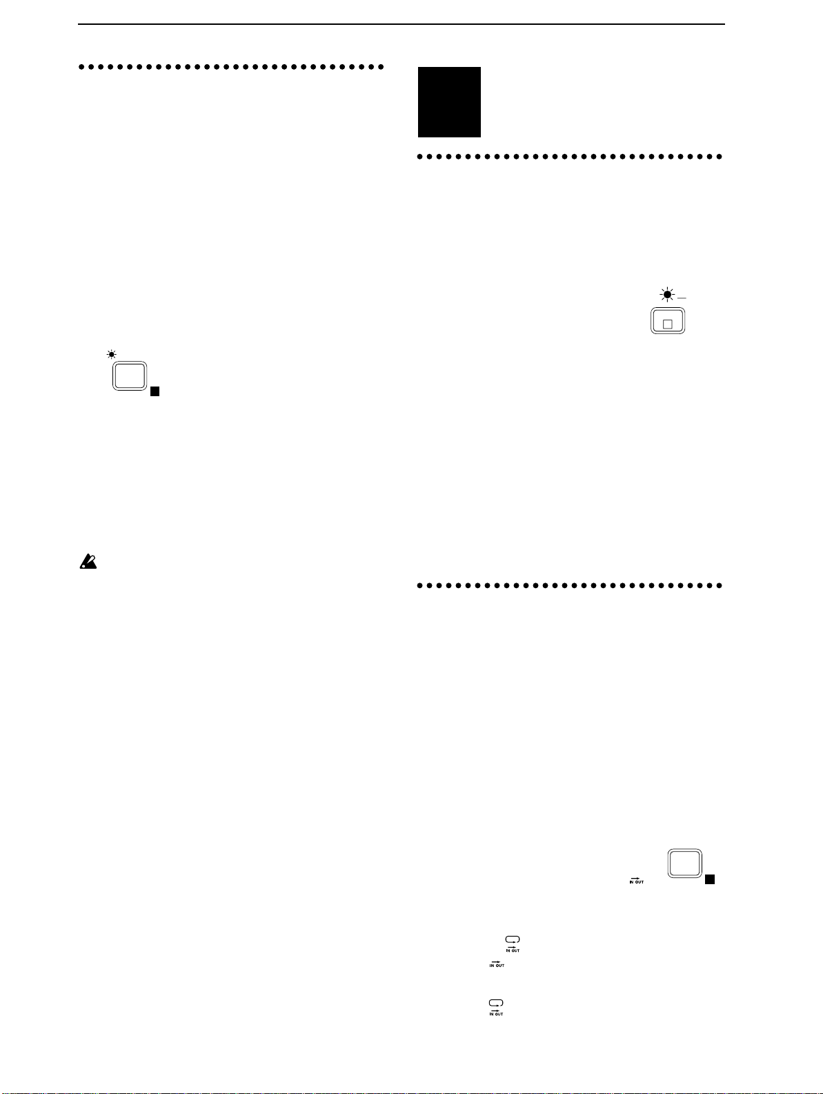
Never turn off the power when the HDD access indicator is lit or blinking. This can damage part or all of
the data on disk, or cause malfunctions such as damage to the hard disk.
■
This device will begin accessing the hard disk immediately after the power is turned on. At this time, the
HDD access indicator will blink, and the display
will indicate “Working.”
until the song name appears in the display and the
HDD access indicator goes dark. The length of time
that the hard disk is accessed after power-on will
depend on the capacity of the hard disk and on
the amount of data on the disk.
If hard disk access continues (e.g., sound contin-
■
ues to be heard) even after playback or recording
operations have been halted, do not turn off the
power until the HDD access indicator has
stopped blinking. In such cases, it is possible that
access may not stop for several minutes or several
tens of minutes.
If damage to the hard disk occurs due to incorrect operation, a power failure, or an accidental interruption of the
power supply, a fee may be charged for repair even if the
unit is still under warrantee.
Never turn off the power
STEP3 Recording
1. Recording (analog recording)................................... 10
2. Recording (digital recording)................................... 11
3. Using EQ to modify the tone as you record........... 11
4. Applying an effect to the input sound
as you record............................................................... 12
5. Applying an effect to the input sound
and recording only the input sound........................ 13
6. Applying the dedicated delay
to the input sound...................................................... 14
7. Listening to recorded tracks while
you record another track (Overdubbing) ............... 14
8. Manually re-recording part
of the performance (Manual Punch In/Out).......... 15
Canceling a recording or editing operation
(Undo/Redo)..................................................................... 15
9. Automatically re-recording part
of the performance (Auto Punch In/Out)..............16
10. Combining multiple tracks into one or two tracks
(Bounce)....................................................................... 17
11. Listening to the metronome while you record ...... 19
12. Trigger recording ....................................................... 20
STEP4 Playback
1. Playback....................................................................... 20
2. Playing a specified area of a song once
or repeatedly............................................................... 20
3. Applying an effect to the playback sound.............. 21
4. Applying an external effect
to the playback sound................................................ 21
5. Program playback of songs....................................... 22
6. Switching scenes during playback........................... 22
....................................................... 10
......................................................... 20
iii
Page 3

STEP5 Moving and storing time locations
1. Moving the current time............................................22
2. Finding a precise time location.................................23
3. Locate points (LOC1, LOC2, LOC3) ........................23
4. Mark points .................................................................24
STEP6 Adjusting and storing mixer settings
1. Pairing settings ...........................................................25
2. Adjusting the volume of each channel....................25
3. Adjusting the stereo location....................................26
4. Using the EQ to adjust the tone................................ 26
5. Adjusting the Effect Send, AUX Send
and Track Status .........................................................26
6. Scene.............................................................................27
STEP7 Mixdown
1. Recording a master tape (Mixdown).......................28
2. Applying an effect during mixdown.......................28
STEP8 Track editing
1. Storing IN, OUT and TO times.................................29
2. Copying track data (Track Copy).............................29
3. Inserting a blank space into the track data
(Insert Track)...............................................................31
4. Erasing data from a track (Erase Track)..................31
5. Deleting data from a track (Delete Track)...............32
6. Exchanging data between tracks (Swap Track) .....32
STEP9 Song editing
1. Copying a song........................................................... 33
2. Deleting a song ...........................................................33
3. Moving a song.............................................................33
4. Song Recover...............................................................33
STEP10 Tempo settings
1. Tempo map settings...................................................34
2. Recording MIDI Clock data from a sequencer.......34
3. Recording tap tempo..................................................35
4. Selecting the tempo source........................................35
..........................................................28
...................................................29
...................................................33
.............................................34
..........22
.....25
STEP13 Saving to and loading from DAT
1. Saving a song to a DAT recorder (Backup) ............41
2. Loading a backed-up song from a DAT recorder
(Restore).......................................................................42
Chapter 3 Reference
1. SONG/TRACK...........................................................44
2. EDIT SONG/TRACK.................................................44
3. SYSTEM .......................................................................47
4. EDIT SYSTEM.............................................................48
5. DISPLAY MODE ........................................................51
6. REC MODE..................................................................51
7. PLAY MODE...............................................................51
8. EDIT PLAY MODE.....................................................52
9. TRIGGER .....................................................................52
10. EDIT TRIGGER...........................................................53
11. TEMPO......................................................................... 53
12. EDIT TEMPO ..............................................................54
13. METRONOME............................................................54
14. EDIT METRONOME..................................................55
15. IN/LOC1, OUT/LOC2, TO/LOC3..........................55
16. SCENE..........................................................................56
17. EDIT SCENE................................................................56
18. STORE..........................................................................57
19. SCRUB..........................................................................57
20. UNDO ..........................................................................57
21. TRACK STATUS.........................................................58
22. EQ .................................................................................58
23. EFFECT SEND ............................................................58
24. PAN/BALANCE........................................................59
25. FADER .........................................................................59
26. PAIR On/Off...............................................................60
27. REC SELECT ...............................................................60
28. EFFECT ........................................................................61
29. EDIT EFFECT..............................................................63
30. EFFECT ASSIGN ........................................................64
31. EDIT EFFECT ASSIGN..............................................64
...........................43
.............41
STEP11 Synchronization and control with a MIDI
sequencer
1. Using MIDI Clock to synchronize
a MIDI sequencer to the D8.......................................36
2. Using MTC to synchronize
a MIDI sequencer to the D8.......................................36
3. Using MMC to control the D8
from a MIDI sequencer..............................................37
STEP12 Using external drives
1. Connecting an external drive....................................37
2. Turning the power on/off
when an external drive is connected .......................38
3. Initializing and formatting a drive...........................38
4. Exchanging disks on a removable disk drive.........38
5. Saving a song on a removable disk drive
(Backup).......................................................................39
6. Loading a song that was backed up
on a removable disk drive (Restore)........................40
.......................................................36
...................................37
iv
Chapter 4 Appendices
1. Troubleshooting..........................................................65
2. Various messages .......................................................67
3. MIDI Implementation Chart.....................................68
4. Block Diagram.............................................................69
5. Effect Program List.....................................................71
6. Effect Parameter List..................................................72
7. Metronm Type List.....................................................75
8. Demo Song List...........................................................75
9. D8 Specifications.........................................................76
Functions added to the D8
Bouncing tracks 1–8..........................................................77
.....................65
..........77
Page 4

7
Chapter 2 Operation
This chapter explains the operation of each of the D8’s functions, in logical order.
Operation
Chapter 2
Connections,
Power-on,
Demo
Page 5
8
1
2
3
4
5
6
7
8
9
Connections,
STEP1
1. Connections to your
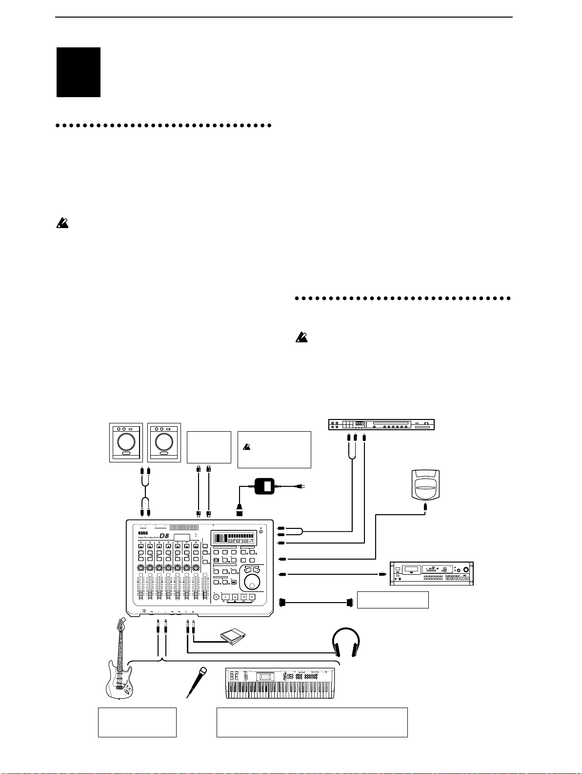
The following diagram shows a basic example of a
D8 recording system. Modify the connections
shown below as needed for your particular setup,
and connect your equipment to the D8.
Be sure to turn off the power before making connections. Failure to do so can damage your speaker
system or cause malfunctions.
Connect the included AC/AC power supply to the
power supply connector of the D8. Then plug the
power supply into an AC outlet.
Connect your audio equipment.
Use an RCA phono cable to connect the OUTPUT
L/R jacks to your amplification system.
If you wish to use headphones for monitoring, con-
nect the phone plug of your headphones to the
PHONES jack. The volume can be adjusted by the
[PHONES] knob located at the left.
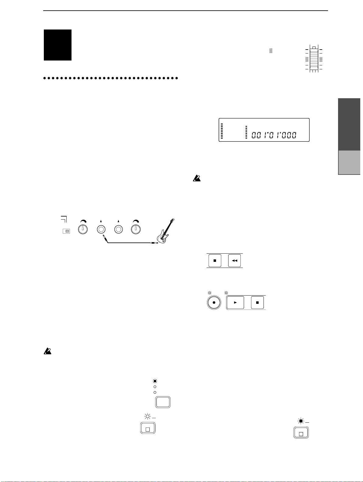
For analog recording, connect the phone plug of
your guitar or mic cable to the INPUT 1 jack. (Refer
to p.11) If you will be doing analog recording in
stereo, connect the cables from the output of your
Power-on, Demo
Here’s how to connect the D8 to your audio
system, and listen to the demo songs.
audio system etc.
stereo device to the INPUT 1 and INPUT 2 jacks.
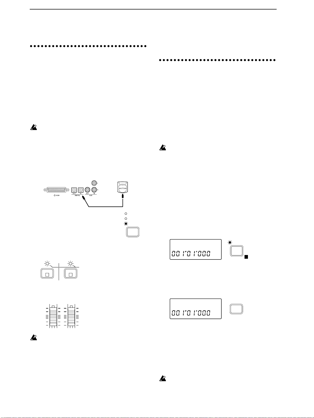
For digital recording, use an optical cable to con-
nect the DIGITAL OUT of your instrument, CD,
MD or DAT player to the DIGITAL IN connector.
(Refer to p.12)
For mixdown to a digital recording device (DAT,
MD etc.), use an optical cable to connect the DIGITAL IN of your recording device to the DIGITAL
OUT of the D8. (Refer to p.30)
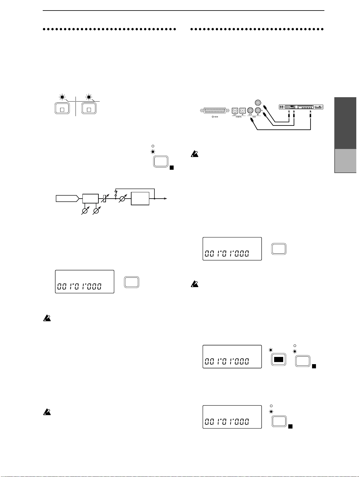
If you wish to use an external effect via AUX IN/
OUT, connect the input of the effect to the AUX
OUT jack, and the outputs of the effect to the AUX
IN jacks. (Refer to p.23)
If you wish to use a foot switch to perform auto
punch in/out, to start/stop playback, or to record
tap tempo, connect a pedal switch PS1 <sold separately> to the FOOT SW jack. (Refer to p.47)
If you wish to synchronize a MIDI sequencer etc. to
the D8, use a MIDI cable to connect the MIDI OUT
of the D8 to the MIDI IN of your sequencer. If you
will be using MMC, connect the MIDI OUT of your
MIDI sequencer. to the MIDI IN jack of the D8.
(Refer to p.38)
2. Power on/off
When the power is turned on, never move the
device or allow it to be jarred. Also, never turn off
the power while the HDD access indicator is blinking (immediately after the power is turned on, during recording or playback, or during track/song
editing). This can damage part or all of the data on
Powered monitors etc.
INPUT
OUTPUT L
·R
RINL OUT
L
EFFECT
EFFECT
SEND
SEND
PAN
D8
PAN PAN PAN PAN PAN BALANCE
LRLRLRLRLRLRLR
GUITAR
TRIM 1 TRIM 2 PHONES FOOT SWINPUT 1 INPUT 2
LINE/MIC
INPUT 1 2
Guitar
Effect device
PROGRAM
MIDI
sequencer
Power supply connection
Use only the included AC/AC power
supply.
OUTPUT
L
WRITE
EDIT
DISPLAY
UTILITY
SELECT
·R
ACHAIN/EFFECT
[BYPASS]
BCDEF
INDIVIDPROGRAM BYPASS
INPUT
Keyboard (digital output),
CD, DAT, MD etc.
POWER
CARD
to the AC outlet
MIDI
IN·OUT
~AC9V
MIDIOUTPUT
TRACK STATUS
GREEN :PLAY
RED :REC
ORANGE
:REC (DIGITAL)
OFF :MUTE
PAIR ON / OFFPAIR ON / OFFPAIR ON / OFF
EFFECT
EFFECT
EFFECT
SEND
SEND
SEND
POWER
HDD
MIDI
(ANALOG)
INPUT 1/2
MASTER
DIGITAL IN
7 / 8LR6R5L4R3L2R1
REC
SELECT
IN/
EFFECT
EQEQEQEQEQEQ
EQ
LOC 1
INPUT 1/2
EFFECT
EFFECT
MASTER
SEND
SEND
STORE
EFFECT
ASSIGN
REHEARSAL
AUTO PUNCH
REC
MODE
TEMPO / MOTRONOME
10
9
8
TEMPO EDIT
7
6
5
4
3
2
REC PLAY
1
0
MASTER7 / 8654321
FOOT SW
AC/AC power supply connector
LOCATOR / SCENE
MODE
SONG/
TO/
OUT/
SYSTEM
TRACK
LOC 3
LOC 2
READ
DISPLAY
UNDO
SCRUBSCENE
MODE
REC / PLAY
PLAY
MODE
METRO
NOME
TRIGGER
STOP REW FF
YES
NO
AUX IN L
·R
AUX OUT
DIGITAL IN
DIGITAL OUT
SCSI
DIGITAL IN
SCSI
DIGITAL OUT
Hard Disk
Removable Disk
Master recorder
(DAT, MD etc.)
Drive
Pedal switch PS-1
PHONES
Mic
Headphones
Keyboard
A guitar or bass can be
directly connected only
to INPUT 1.
If you will be recording only on one track, connect your instrument to INPUT 1.
INPUT 2 is used only when simultaneously recording two tracks.
Page 6

9
1
2
3
4
5
1
2
3
4
5
1
0 . 2
3
4
5
6
-
disk, or cause malfunctions such as damage to the
hard disk or internal mechanism.
3. Listening to the demo
Turning the power on
■
Turn on the power of the connected devices.
Set the volume of all devices to the minimum position, and turn on the power switches starting with
the first device in the signal chain. If external
drives are connected, refer to p.40.
Turn down the D8’s master fader. Set
the volume controls of all connected
devices to the minimum position.
Turn on the power of your input devices and master recorder (DAT etc.).
Press the [POWER] switch of the D8 to turn on the
power.
POWER
ON OFF
The display will shown an opening message for a
brief time, and then the song which was last selected
when the power was turned off will appear.
Turn on the power of your powered monitor speakers, and raise the volume of the connected equipment to an appropriate level.
■ Turning the power off
Before turning the power off, make sure that all
song recording or playback has been completed.
The audio that you record to the D8 will be saved
automatically. However, if you edit effect settings
or adjust the mixer, these settings will be lost
unless they are saved. For the saving procedures,
refer to p.13, for saving effect settings, and to p.29
for saving mixer settings (scenes).
Lower the volume of each connected device to the
minimum position and turn the power off starting
with the last device in the signal chain. If external
drives are connected, refer to p.40.
If you wish to keep any edits you have made to the
effects or to the mixer settings, store them.
Turn off the power of your amplification system.
Press the [POWER] switch to turn off the power of
the D8.
Turn off the power of the audio input devices etc.
10
9
8
7
6
5
4
3
2
1
0
MASTER
songs
When shipped from the factory, the D8 contains
pre-recorded demo songs. Playback to the demo
songs to experience the dynamic and clear sound
of the D8.
Move the D8’s [CHANNEL] faders 1–7/8 to the
unity gain position (the “ ” symbol in the fader calibrations), and set the [MASTER] fader to
3
2
1
0
MASTER7 / 81
Select the song that you wish to playback.
01:Scukyll
✧
To select the next song, hold down the [STOP] key
and press the [FF] key. If there is no subsequent
song, the display will indicate “NoDATA”.
To select the previous song, if you are at the begin-
✧
ning of the song (“001
[STOP] key and press the [REW] key. If you are
located elsewhere than the beginning of the song,
move to the beginning of that song. Then hold
down the [STOP] key and press the [REW] key to
move to the previous numbered song.
PLAY STOP REW FF
Make sure that the indicators above the [TRACK
STATUS] keys of tracks 1–7/8 are lit green. If they
are off or lit with a different color, press that
[TRACK STATUS] key as many times as necessary
to make each indicator light green.
lit green
1
L
Press the [PLAY] key to begin playback.
Gradually move the [MASTER] fader upward to
adjust the volume to an appropriate level.
As the song plays back, you can move the [CHAN-
NEL] faders and [PAN] knobs, and adjust the EQ
(refer to p.27, p.28) and effect send amount (refer to
p.23), or change the effect program (refer to p.13) to
see how the sound of the song is altered.
When the demo song finishes playing, press the
[STOP] key to stop playback.
01:Scukyll Express
02:Moonlit sea
(Refer to p.75)
M
B
01
000” etc.) hold down the
To next song/
Create new song
To beginning of song/
To previous song
7 / 8
LR
Operation
Chapter 2
Creating
and select
ing songs
Page 7
10
1
2
1
2
3
4
2
1
2
3
P1
P1
P1
Creating and
STEP2
to create and name a song, and how to select songs in
EDIT SONG/TRACK .
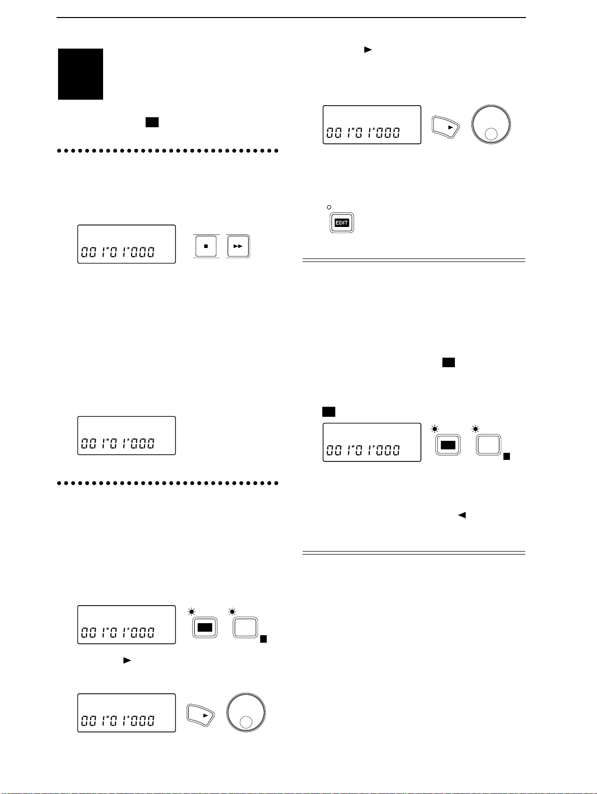
1. Creating a new song
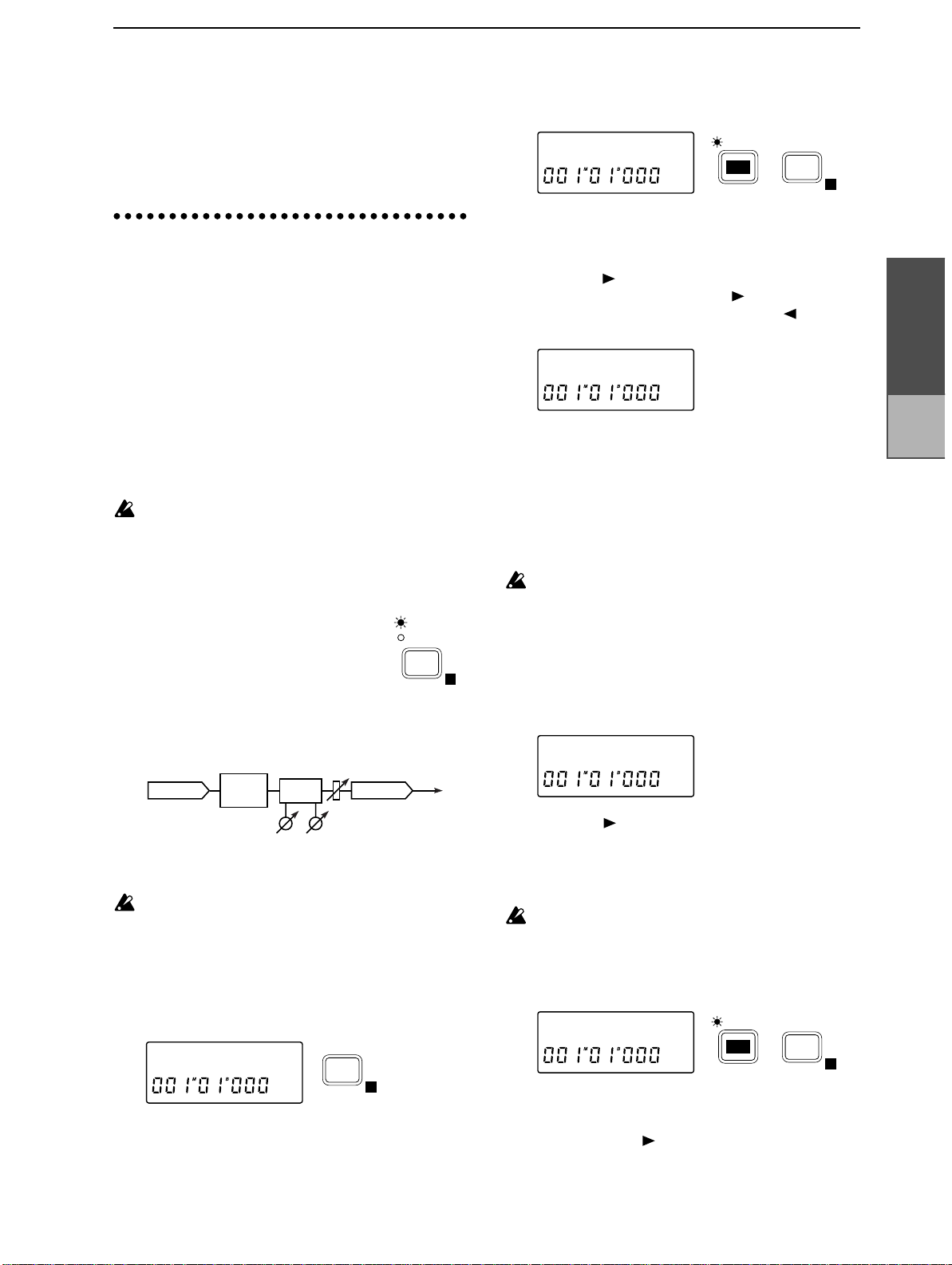
After selecting the last-numbered song, hold down
the [STOP] key and press the [FF] key.
The display will indicate “NoDATA”.
Use one of the following procedures to create a
song.
•
•
•
selecting songs
To record a new song, you must first create a new song. This section explains how
STOP FF
03:NoDATA
Change the song name from “NoDATA”.
In our example here, we will create a song by
changing the song name. Refer to “2. Naming a
song”.
Record audio data on a track. The display will
indicate “NEWSONG” as the song name.
Specify the tempo or time signature. A tempo
map will be created in the tempo track, and the
display will indicate “NEWSONG” as the song
name.
Press the [ ] key several times to move the cursor
to the location where you wish to change the name,
and use the [VALUE] dial to input alphabetical
characters or symbols to specified the desired
name.
KORG1 œ
When you finish inputting the name, press the
[EDIT] key (the indicator will go off) to exit the
EDIT SONG/TRACK page. The name will be finalized when you exit this page.
YES
Selecting another song
There are two ways to select songs. One way is to
hold down the [STOP] key and press the [FF] key
to select the next song number , or to hold down the
[STOP] key and press the [REW] key to select the
previous song number (refer to “Listening to the
demo songs”, step
song in EDIT SONG/TRACK .
After pressing the [EDIT] key, press the [SONG/
TRACK] key several times to get a song name display such as “I04:KORG1”. (EDIT SONG/TRACK
)
). The other way is to select the
03:NEWSONG
2. Naming a song
In order to distinguish your new song from other
songs, it is recommended that you give it a name.
Press the [EDIT] key (the indicator will light), and
then press the [SONG/TRACK] key to access the
“Edit Song” display.
If this display does not appear, press the [SONG/
TRACK] key until the “Edit Song” appears.
EditSong ˙
Press the [ ] key, and then press the [SONG/
TRACK] key several times to get the “Renam” display.
Renam˘I03˙
EDIT
YES
SONG /
TRACK
I03:KORG1
Rotate the [VALUE] dial to select the song number.
If you have connected an external drive such as a
hard disk drive or removable disk drive and wish
to select a song from it, press the [ ] key and then
rotate the [VALUE] dial to select the connected
drive.
E
EDIT
SONG /
TRACK
E
Page 8
11
1.
1
2
3
4
5
6
7
8
9
10
11
12
13
d
Recording
STEP3
Normally you will record rhythm instruments such
as drums first, and then listen to these instruments
playback as you record bass, guitar and vocals.
As basic recording procedures, we will explain
how to record a single track, and how to record
two tracks simultaneously.
■
Connecting the input device and adjusting
the level
Turn down the [MASTER] fader of the D8, and
connect your instrument to the INPUT 1 jack. If
you are recording a single track, you must use the
INPUT 1 jack for connections. The INPUT 2 jack is
active only when two tracks are being recorded
simultaneously.
GUITAR
LINE/MIC
✧
If you wish to record two tracks simultaneously,
make connections to the INPUT 1 and INPUT 2 jacks.
If you are using an electric guitar or bass, connect it to
the INPUT 1 jack (in preference to the INPUT 2 jack).
If you are recording in stereo, connect the left channel
output of the instrument to the INPUT 1 jack, and the
right channel output to the INPUT 2 jack.
Use the [GUITAR-LINE/MIC] switch to select the
appropriate input impedance for the instrument
connected to INPUT 1 jack.
GUITAR : Select this position when inputting an
MIC/LINE : Select this position when inputting a
The [GUITAR-LINE/MIC] switch is only for the
INPUT 1 jack. If you wish to connect a guitar/bass
to the INPUT 2 jack, route it through a compact
effect unit etc.
Press the [REC SELECT] key several
times to select
Press the channel 1 [TRACK
STATUS] key several times to
select
tor blinking red) to choose it as
the recording track.
If you are recording two tracks simultaneously,
✧
press the [TRACK STATUS] keys for two adjacent
odd/even tracks (1-2, 3-4, 5-6, 7/8) to select
This section explains the various methods
of recording that are available on the D8.
Use the recording method that is appropriate for your needs.
Recording (analog recording)
TRIM 1 TRIM 2INPUT 1 INPUT 2
instrument that has a high output
impedance, such as guitar or bass.
mic or a line instrument (keyboard,
mixer etc.).
INPUT 1/2 (indicator lit).
REC (ANALOG) (indica-
1
L
INPUT 1/2
MASTER
DIGITAL IN
REC
SELECT
blinking re
REC
(ANALOG)
(indicator lit red), to choose them as
the recording tracks.
Set the [CHANNEL] fader to the
unity gain position (the “ ” symbol
in the fader calibrations).
Raise the volume of the instrument connected to
the INPUT 1 jack as high as possible, and while
watching channel level 1 in the display, rotate the
[TRIM 1] knob toward the right to adjust the
recording level.
CLIP
–3
03:KORG1
–6
–12
–18
–24
1 2 3 4 5 6 7 8
If you are recording two tracks simultaneously, set
✧
–40
dB
E L R
the [CHANNEL] faders of both tracks you wish to
record to the unity gain position, and use the [TRIM
1]/[TRIM 2] knobs to adjust the recording level.
Adjust the settings so that the input level is as high
as possible without causing the “CLIP” indicator
to light.
■
Starting and stopping recording
Record from the beginning of the track. Make sure
that the location counter reads “001
M
01
B
000”. If a
different time is selected, hold down the [STOP]
key and press the [REW] key to return the current
time to the beginning of the song.
STOP REW
Press the [REC] key (the [REC] and [PLAY] indicators will blink) to enter record ready mode.
REC PLAY STOP
Press the [PLAY] key and recording will begin (the
[REC] and [PLAY] indicators will light). Begin
playing your instrument.
When you finish playing, press the [STOP] key to
stop recording. (The [PLAY] and [REC] indicator
will go off.)
Listening to the recorded performance (Play-
■
back)
Now let’s listen to the performance that was
recorded.
Hold down the [STOP] key and press the [REW]
key to return to the beginning of the song.
Press the [TRACK STATUS] key
for the track(s) that you
recorded to select
PLAY (indica-
tor lit green), to select playback.
Press the [PLAY] key to begin playback (indicator
is lit).
1
L
1
lit green
Operation
Chapter 2
Recording
Page 9
12
14
2.
When playback ends, press the [STOP] key to stop
playback (the [PLAY] indicator is off).
Recording (digital recording)
Here’s how to record digitally from an instrument
which has a digital output or from an external digital device such as a CD or DAT player. Since the
digital input of the D8 provides a sampling rate
converter, 48 kHz and 32 kHz sources will be converted to 44.1 kHz as they are recorded.
As an example, we will record in stereo to tracks 3
and 4. When recording two tracks simultaneously,
you will use an odd/even pair of adjacent tracks
(1-2, 3-4, 5-6, 7/8).
During digital recording, the effect will be off, and it
will not be possible to use effects on any other track.
■ Connecting the input device and adjusting
the level
1 Turn down the [MASTER] fader or the D8, and
connect the digital output of your keyboard, CD or
DAT to the D8’s DIGITAL IN connector.
2 Press the [REC SELECT] key to
select DIGITAL IN (indicator lit).
INPUT 1/2
MASTER
DIGITAL IN
REC
SELECT
back)
6 Refer to “1. Recording (analog recording), ■ Listening
to the recorded performance (Playback)”, and listen to the playback.
3. Using EQ to modify the
tone as you record
Here’s how the built-in 2-band equalizer (EQ) can
be applied to the input sound to modify the tone,
so that the modified tone can be recorded.
■ Connecting the input device and adjusting
the level
1 Referring to the previous section “1. Analog
recording” or “2. Digital recording”, connect the
device that you wish to record, and adjust the level.
During analog recording, if the input level adjusted
by [TRIM 1] and [TRIM 2] is inappropriate, the input
sound may distort, or there may be unwanted noise.
When the Channel Level Meter Select (refer to p.47) is
set to Post, the channel level meters will indicate the
volume level between the EQ and the [CHANNEL]
faders. This means that if you apply EQ or set the faders to a position other than unity gain (or if you set
the effect [EFFECT ASSIGN] to INPUT 1/2), it will
not be possible to check just the input level.
✧ Press the [SYSTEM] key several times to make the
display read “ChMtr”, and rotate the [VALUE] dial to
select Pre. Rotate the [TRIM 1] and [TRIM 2] knobs to
adjust the input level as high as possible without
causing the “CLIP” indicator of the channel level
meters to light. After making adjustments, rotate the
[VALUE] dial to return the “ChMtr” setting to Post.
3 Press the [TRACK STATUS] keys of channels 3 and
4 to select REC (DIGITAL) (indicator blinking
orange), to choose tracks 3 and 4 for recording.
blinking orange
3
L
4 Watch the channel level meters in the display, and
raise or lower the [CHANNEL] faders of channels 3
and 4 to adjust the recording level of tracks 3 and 4.
Adjust the settings so that the input level is as high as
possible without causing the “CLIP” indicator to light.
4
R
43
■ Starting and stopping recording
5 Refer to “1. Recording (analog recording),
■ Starting and stopping recording”, and record
your performance.
■ Listening to the recor ded perf ormance (Play-
ChMtr:Pre
SYSTEM
E
■ Adjusting the EQ
2 Press the [EQ] key of the channel whose tone you
wish to adjust, to make the display read “LEQ✽”
or “HEQ✽” (✽ is the channel number). Then rotate
the [VALUE] dial to adjust the EQ.
HEQ1 :+03
EQ
■ Starting and stopping recording
3 Refer to “1. Recording (analog recording) ■ Start-
ing and stopping recording” to record.
■ Chec king the recorded material (Pla yback)
4 When you finish recording, refer to “1. Recording
(analog recording) ■ Listening to the recorded performance (Playback)” and playback your performance.
If the Input Monitor (refer to p.47) is set to AUTO,
the EQ and fader will affect only the input sound
for tracks whose [TRACK STATUS] is set to REC,
and will not affect the playback sound. By playing
Page 10
13
back with the [TRACK STATUS] left at REC, you
will be able to audition the sound just as it was
actually recorded.
If you set the [TRACK STATUS] to PLAY and play-
back without changing the EQ settings the EQ will
be applied double, so remember to set the EQ
value back to 0.
4. Applying an effect to the
input sound as you record
You can apply the internal effect of the D8 to the
instrument connected to the INPUT 1/2 jack, and
record the sound that has been processed by the
effect.
■ Connecting the input device and adjusting
the level
1 Refer to “■ Connecting the input device and adjusting
the level” (p.11, p.12), to connect the input device and
adjust the level.
It is not possible to use the effect when recording
digitally.
■ Selecting the location at which the eff ect will
be inserted
2 Press the [EFFECT ASSIGN] key
several times to select INPUT 1/2
(indicator lit).
With a setting of INPUT 1/2, the internal effect will
be inserted between the input and the EQ of the
mixer channel whose [TRACK STATUS] is set to
REC.
FADER
INPUT
Effect
[EQ]
RecTrack
INPUT 1/2
MASTER
EFFECT
ASSIGN
OUTPUT
E
(Refer to p.61) After pressing the [EDIT] key, press
the [EFFECT] key several times to select the effect
that you wish to edit.
DISTORT:o˙
7 Rotate the [VALUE] dial to specify whether the
effect you selected in step 6 will be used “o” (on) or
not “-” (off).
8 Press the [ ] key to select the effect parameter that
you wish to edit. Pressing the [ ] key will move to
the next parameter, and pressing the [ ] key will
move to the previous parameter. (Refer to p.72)
EDIT
EFFECT
E
TYPE:DIST˙
9 Rotate the [VALUE] dial to modify the value.
■ Saving the effect program
If you wish to use the edited effect program in this
song, or to use it in more than one song as a general-purpose effect, you must save the effect program in the user bank.
An edited effect which has not been saved will be
lost if you perform one of the following actions.
• Select another effect program
• Select another song
• Turn off the power
10 Press the [EFFECT] key several times to make the
display read “Ren
name).
→✽✽✽” (✽ is the effect program
Ren˘ROCK
Operation
Chapter 2
Recording
HEQ LEQ
3 Adjust the following effect settings while listening to
the input sound of the instrument or other source.
Adjust the [TRIM] knob so that the effect (“E”)
level meter does not light all the way to CLIP.
■ Selecting the effect program
4 Press the [EFFECT] key several times to access the
display page for selecting an effect program, as
shown below.
EG1:ROCK
5 Rotate the [VALUE] dial to select an ef fect program.
EFFECT
E
■ Editing the effect
6 Each effect program consists of up to four effects.
11 Press the [ ] key several times to move the cursor
to the location where you wish to modify the
name, and rotate the [VALUE] dial to enter alphabetical characters or symbols to assign the desired
name.
is a special symbol. Once this display is modi-
œ
fied, it cannot be selected newly.
12 Press the [EFFECT] key to access the “Write
display. (U indicates the user bank area, and ✽✽ is
the effect number.)
Write˘U01?
13 Rotate the [VALUE] dial to select the save destina-
tion in which the effect program will be saved.
14 Hold down the [ ] key for approximately one sec-
ond to save the effect program and its name. When
the data has been saved, the display will indicate
“Completed”.
EDIT
→U✽✽”
EFFECT
E
Page 11
14
When you execute the Save operation, the effect
program that previously occupied that memory
will be overwritten and lost.
■ Starting and stopping recording
15 Press the [REC] key, and then press the [PLAY] key
to begin recording. Press the [STOP] key to stop
recording. (Refer to ■ “Starting and stopping
recording”, p.11)
■ Listening to the recor ded perf ormance (Play-
back)
16 Move the current time to a location earlier than the
point at which you began recording. Then set the
[TRACK ST ATUS] of the recorded track to PLAY, and
press the [PLAY] key to begin playback. Press the
[STOP] key to stop playback. (Refer to “■ Listening
to the recorded performance (Playback)”, p.1 1)
5. Applying an effect to the
input sound and recording only the input sound
Here’s how you can apply the D8’s internal effect
to the sound of an instrument or other sound
source connected to the INPUT 1 jack or INPUT 2
jack. In this section, only the input sound is
recorded. Use this method when you wish to try a
variety of effects during playback and decide on
the final sound later.
■ Connecting the input device and adjusting
the level
1 Refer to “■ Connecting the input device and
adjusting the level” (p.11, p.12), to connect the
input device and adjust the level.
It is not possible to use the effect when recording
digitally.
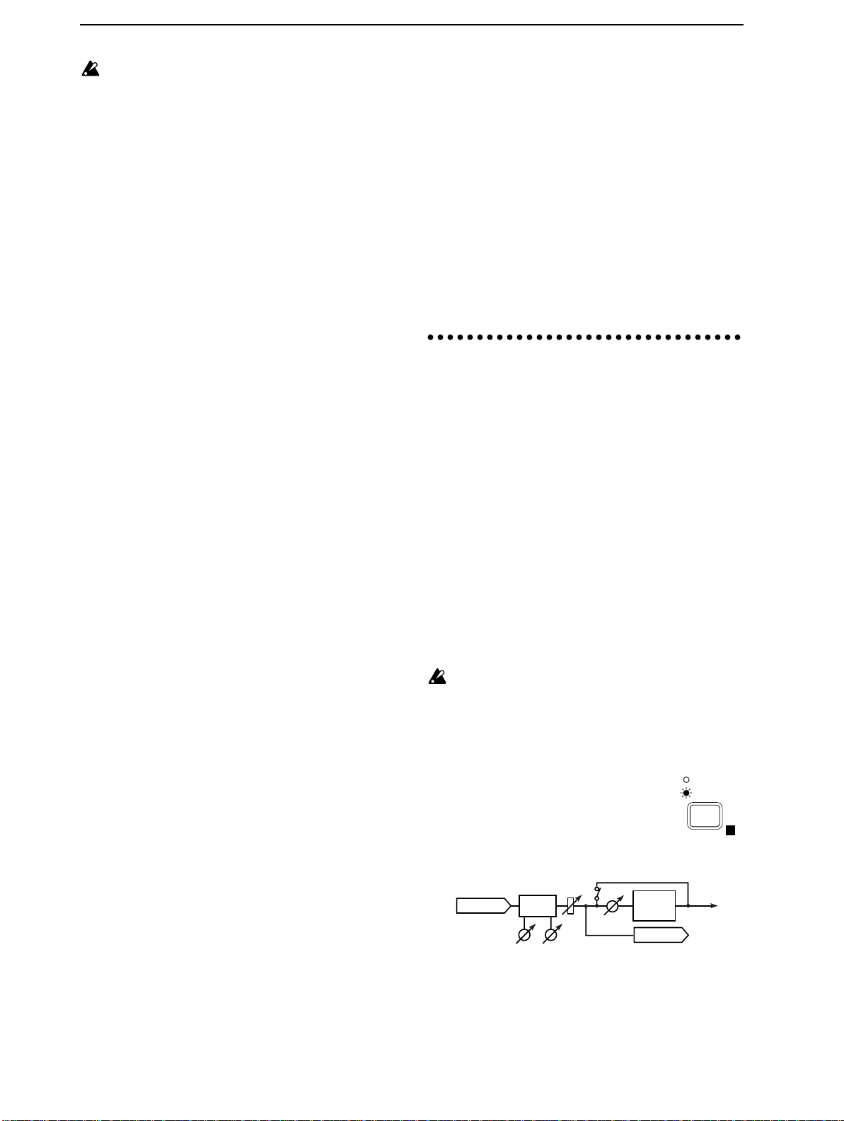
■ Selecting the location at which the eff ect will
be inserted
2 Press the [EFFECT ASSIGN] key
several times to select MASTER
(Send Type) (indicator lit). With the
setting MASTER (Send Type), the
send bus will be output to the internal effect, which will be output to
the master bus.
FADER
INPUT
3 Adjust the following effect settings while listening
to the input sound of the instrument or other source.
[EQ]
HEQ LEQ
Effect
Snd
RecTrack
INPUT 1/2
MASTER
EFFECT
ASSIGN
OUTPUT
E
■ Sending the input sound to the effect
4 Press the [EFFECT SEND] key several times for the
input channel where you wish to apply the effect,
Page 12
15
to access the “Snd✽” display (✽ is the channel
number).
6. Applying the dedicated
Snd1 :000
5 Rotate the [VALUE] dial to adjust the amount of
the input sound that will be sent to the effect.
Be careful that the effect (“E”) level meter does not
light all the way to CLIP.
EFFECT
SEND
■ Selecting the effect program
6 Select the effect program as explained in “4.
Applying an effect to the input sound as you
record, ■ Selecting the effect program”.
■ Adjusting the return level from the effect and
the return balance
7 Press the [EDIT] key, and then press the [EFFECT
ASSIGN] key several times to access the “EffRet”
(effect return level) display.
INPUT 1/2
E
MASTER
EFFECT
ASSIGN
E
EffRet:080
EDIT
8 Rotate the [VALUE] dial to adjust the return level
from the effect.
9 Press the [EFFECT ASSIGN] key to access the “Eff-
Bal” (effect return balance) display.
INPUT 1/2
EffBal:CNT
10 Rotate the [VALUE] dial to adjust the return bal-
ance from the effect.
MASTER
EFFECT
ASSIGN
■ Saving the effect program
11 Refer to “4. Applying an effect to the input sound
as you record, ■ Editing the effect, ■ Saving the
effect program”.
■ Starting and stopping recording
12 After pressing the [REC] key, press the [PLAY] key
to begin recording, and press the [STOP] key to
stop recording. (Refer to p.11, “■ Starting and
stopping recording”)
■ Checking the recorded material (Playback)
13 Move the current time to a point earlier than where
you began recording. Then set the [TRACK STATUS] to PLAY for the track that you recorded, press
the [PLAY] key to playback, and press the [STOP]
key to stop. (Refer to p.11, “■ Listening to the
recorded performance (Playback)”)
delay to the input sound
In addition to the effect that was discussed in “4.
Applying an effect to the input sound as you record”
and “5. Applying an effect to the input sound and
recording only the input sound”, the D8 provides a
“monitor delay” that can be applied only to the input
sound. When you are recording vocals or guitar,
applying this delay will give the sound a sense of
spaciousness. This delay will not be recorded. Since
the monitor delay is not part of the internal effect, it
lets you use the internal effect in other ways.
■ Connecting the input device and adjusting
the level
1 Refer to “1. Recording (analog recording), ■ Connect-
ing the input device and adjusting the level” to connect the input device and adjust the level.
It is not possible to use the effect or the monitor
delay when recording digitally.
■ Turning the monitor delay on/off
2 Press the [EFFECT ASSIGN] key
several times to select INPUT 1/2
(indicator lit).
3 Press [EFFECT] several times to access the
“MoniDly” display.
MoniDly:o˙
4 Rotate the [VALUE] dial to turn the monitor delay
on (o).
When [EFFECT ASSIGN] is set to INPUT 1/2 and
[REC SELECT] is set to INPUT 1/2, turning the
monitor delay on will only apply to tracks whose
[TRACK STATUS] is REC (ANALOG), and the
monitor delay will apply to the sound that is input
from the INPUT 1/2 jacks.
EFFECT
■ Editing the monitor delay
5 Press the [ ] key to select the monitor display
parameter that you wish to edit. Press the [ ] key
to move to the next parameter, or press the [ ]
key to move to the previous parameter (refer to
p.74).
T :200ms
6 Rotate the [VALUE] dial to set the value.
INPUT 1/2
MASTER
EFFECT
ASSIGN
E
E
Operation
Chapter 2
Recording
Page 13
16
7. Listening to recorded tracks
8. Manually re-recording
while you record another
track (Overdubbing)
The process of recording additional tracks while
you listen to previously recorded tracks is called
“overdubbing”.
As an example, we will explain how you can playback the sound that was recorded on track 1, and
perform analog recording on track 2.
■ Select the playback/recording tracks
1 Press the track 1 [TRACK STATUS] key several
times to select PLAY (indicator lit green), to enable
(the previously recorded) track 1 for playback.
blinking redlit green
1
L
2 Press the track 2 [TRACK STATUS] key to select
REC (ANALOG) (indicator blinking red), to
enable it as the recording track.
3 Either turn down [CHANNEL] faders 3–7/8, or
press their [TRACK STATUS] keys several times to
select MUTE (indicator off), to mute these tracks so
that they will not sound during playback.
■ Connecting the input device for the record-
ing track and adjusting the level
4 As shown in “■ Connecting the input device and
adjusting the level” (p.11, p.12), connect an instrument etc. to the INPUT 1 jack, and set the input
level.
5 Raise or lower the [CHANNEL] fader of the play-
back track to a volume that will be comfortable for
playing along with.
2
R
part of the performance
(Manual Punch In/Out)
If you made a mistake during the performance that
you recorded, or if you were not able to play the
entire song as you had intended, there is no need
to re-record the entire song — you can re-record
just the part that you need.
“Punch In” is the action of switching from song
playback to record, and “Punch Out” is the action
of switching back from recording to playback.
“Manual Punch In/Out” is when you perform the
Punch In and Punch Out manually. On the D8, you can
Punch In during playback either by pressing the [REC]
key or by pressing a foot switch <sold separately>. You
can Punch Out by pressing either the [REC] key or the
[PLA Y] key, or by pressing a foot switch.
(playback) (recording) (playback)
REC
or
Foot switch
■ Connecting the input device and adjusting
the level
1 As explained in “■ Connecting the input device
and adjusting the level” (p.12), connect the input
device and adjust the level. At this time, make
adjustments so that there is no difference between
the volume of the instrument that is being input
and the volume of the track.
■ Select the input monitor
2 Press the [SYSTEM] key several times (indicator lit)
to access the “Mon” display. Then rotate the
[VALUE] dial to select Auto.
Mon:Auto
Stop recordingBegin recording
REC
PLAY
or or
Foot switch
SYSTEM
E
■ Starting and stopping recording
6 Press the [REC] key, and then press the [PLAY] key
to begin recording. Press the [STOP] key to stop
recording. (Refer to “■ Starting and stopping
recording”, p.11)
■ Listening to the recor ded perf ormance (Play-
back)
7 Move the current time to a location earlier than the
point at which you began recording. Then set the
[TRACK STATUS] of the recorded track to PLAY,
and press the [PLAY] key to begin playback. Press
the [STOP] key to stop playback. (Refer to
“■ Listening to the recorded performance (Playback)”, p.11)
■ Starting and stopping recording
3 Move the current time location to a point earlier
than the location that you wish to re-record. If you
hold down the [STOP] key and press the [REW]
key, you will move to the beginning of the song.
4 Press the [PLAY] key (indicator lit) to
begin playback.
The [TRACK STATUS] indicator which
was set to REC will blink, and you will
hear the sound of the track.
For tracks whose [TRACK STATUS] is set to REC,
the EQ and fader will affect only the input sound,
and will not affect the playback sound. After
adjusting the input level, do not modify the fader
or EQ settings during playback, since this will
change the volume and EQ of the input sound.
5 When you wish to begin re-
recording, press the [REC] key
(Manual Punch In). The
[TRACK ST ATUS] indicator will
REC
2
R
2
R
Page 14
17
change from blinking to lit, and the D8 will enter
record mode. Now you will hear the external input
sound. Begin playing, and your playing will be
recorded.
6 When you wish to stop recording, you can either
press the [REC] key once again or press the [PLAY]
key to change from recording back to playback.
(Manual Punch Out)
The [TRACK STATUS] indicator will blink, the
[REC] indicator will go off, and you will hear the
track sound once again.
7 Press the [STOP] key (the [PLAY] indicator will go
off) to stop song playback.
■ Listening to the recor ded perf ormance (Play-
back)
8 Move the current time location to a point earlier
than where you began re-recording. Then set the
[TRACK STATUS] of the recorded track to PLAY,
and press the [PLAY] key to begin playback. Press
the [STOP] key to stop. (Refer to “■ Listening to
the recorded performance (Playback)”, p.11)
Also, playing back with [TRACK STATUS] set to
REC will allow you to hear the sound just as it was
recorded, without passing through the fader or EQ.
■ Using a foot switch for Manual Punch In/Out
By pressing a foot switch (sold separately), you can
switch between playback and recording while you
play an instrument, or from a remote location. This
method can also be used when you wish to begin
recording immediately from the precise beginning of
the song.
✧ Connect your foot switch to the FOOT SW jack.
Press the [SYSTEM] key several times (indicator lit)
to access the “Fsw” display. Then rotate the
[VALUE] dial to select PncI/O. Now you will be
able to press the foot switch instead of pressing the
[REC] key in steps 5 and 6 of the above procedure.
Fsw:PncI/O
✧ If you wish to start recording from the very begin-
ning of the song, press the [REC] key at the beginning of the song (the indicator will blink), and
press the foot switch to start recording.
SYSTEM
E
Canceling a recording or editing operation (Undo/Redo)
After you have recorded, or performed an
editing operation such as track copy or
delete (discussed later in this manual),
you have the option of restoring the data to its original state. After you have recorded, performed a
track editing operation, or used the Redo function, a
“ ” symbol will appear in the right of the display.
When this is displayed, you have the option of
using the Undo function to restore the data to its
previous state. After the Undo function has been
used, a “ ” symbol will appear and you can use
the Redo function to recover the state prior to using
Undo.
UNDO
■ Undo
✧ After recording or track editing, or after the Redo
function has been used, the display will show a
“ ” symbol. Press the [UNDO] key to execute
Redo, and the data will return to its previous state.
■ Redo
✧ After executing the Undo function, the display will
show a “ ” symbol. Press the [UNDO] key to
execute Redo, and the data will return to the state
prior to using Undo.
9. Automatically re-recording
part of the performance
(Auto Punch In/Out)
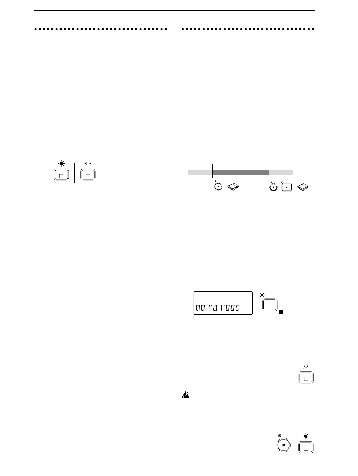
“Auto Punch In/Out” is a function which automatically performs Punch In and Punch Out at previously-specified time locations in the song. This
allows you to accurately re-record a specific portion
of a recording. Auto Punch In/Out is convenient
when you wish to concentrate on your playing.
(playback) (recording) (playback)
Pre roll
time
IN
(LOC 1)
■ Storing the IN and OUT times
Storing the location at which recording will begin
as the IN (punch in) time, and the location at which
recording will end as the OUT (punch out) time.
1 Move the current time location to the point where
you wish to begin recording. (Refer to “1. Moving
the current time”, p.24)
2 Press the [STORE] key to prepare for storing the
location. The display will indicate “Store”.
Store˘
3 Press the [IN/LOC 1] key . The display will indicate
“Store
→In (destination)”, and the IN (punch in)
time will be stored.
Release the key, and you will return to the previous
page.
Store˘In
4 As described in steps 1–3 above, move the current
time location to the point where you wish to stop
recording, press the [STORE] key, and then press
the [OUT/LOC 2] key to store the time location in
OUT (punch out).
✧ You can also store the IN (punch in) and OUT
(punch out) points while the song plays back. Press
the [STORE] key, and then press the [IN/LOC 1]
key at the time where you want to begin recording.
In the same way, press the [STORE] key and then
press the [OUT/LOC 2] key at the time where you
want to stop recording.
Stop recordingBegin recording
IN /
LOC 1
OUT
(LOC 2)
Post roll
time
Operation
Chapter 2
Recording
Page 15
18
■ Connecting the input device and adjusting
the level
5 As explained in “■ Connecting the input device
and adjusting the level” (p.11, p.12), connect the
input device and adjust the level. At this time,
make adjustments so that there is no difference
between the volume of the instrument that is being
input and the volume of the track.
■ Select the input monitor
6 Press the [SYSTEM] key several times (indicator lit)
to access the “Mon” display (refer to SYSTEM P3).
Then rotate the [VALUE] dial to select Auto.
Mon:Auto
SYSTEM
E
■ Auto Play function and Auto Repeat function
When performing Auto Punch In/Out, it is convenient to use the Auto Play function or the Auto
Repeat function in conjunction with Auto Punch
In/Out (refer to p.51, p.52).
When the Auto Play function is on, pressing the
[REC] key and then pressing the [PLAY] key will
automatically move to the pre-roll time and begin
playback. Then the IN–OUT area will be recorded,
and the post-roll time will playback, and finally
playback will stop automatically. In addition, if
Auto Repeat is on, the Auto Play function will
occur as described above, and then you will move
to the pre-roll time without stopping and continue
playing back to the post-roll time.
7 Pressing the [PLAY MODE] key once
will make the display show “ ”, and
the Auto Play function will be turned
on. Pressing the [PLAY MODE] key
PLAY
MODE
E
once again will make the display show
“ ”, and the Auto Repeat function will be on.
8 Press the [EDIT] key, then press the [PLAY MODE]
key several times to make the display read “PreRol”, and specify the pre-roll time. Rotate the
[VALUE] dial to specify the value. Press the [ ]
key and rotate the [VALUE] dial to set the unit to
either measures (M) or seconds (s).
PstRol:02M
EDIT
PLAY
MODE
E
9 Press the [PLAY MODE] key to make the display
read “PstRol”, and referring to step 8, set the post-roll
time. After making the setting, press the [EDIT] key.
* Subsequent steps 10–18 are for when the Auto
Play function is on. If you are not using the Auto
Play/Repeat functions together, set the current
time to a location earlier than the IN time, and then
begin recording or playback.
■ Rehearsing auto punch in/out
Before you actually perform auto punch in/out
recording, it is a good idea to rehearse the recording. If you do not need to rehearse, proceed to
“■ Auto punch in/out setting”.
10 Press the [REC MODE] key several
times to select AUTO PUNCH +
REHEARSAL (both indicators lit).
When AUTO PUNCH +
REHEARSAL
AUTO PUNCH
REC
MODE
REHEARSAL is selected, initiating
recording will cause the input monitor etc. to function in the same way as if recording were actually
being performed. This allows you to rehearse the
recording.
11 Press the [REC] key ([REC] and [PLAY] indicator
will blink), and then press the [PLAY] key ([REC]
and [PLAY] indicator lit) to begin playback. The
[TRACK ST ATUS] indicator that was set to REC will
blink, and the track playback sound will be heard.
For tracks whose [TRACK ST ATUS] is REC, the EQ
and fader will affect only the input sound, and will
not affect the playback sound. After adjusting the
input level, do not modify the fader or EQ settings
during playback, since this will change the volume
and EQ of the input sound.
12 When the IN time location is reached, the [TRACK
STATUS] indicator will change from blinking to lit,
the [REC] indicator will begin blinking, and the
external input sound will be heard. Begin rehearsing your performance.
13 When the OUT time location is reached, the
[TRACK STATUS] indicator will blink, the [REC]
indicator will go dark, and the track playback
sound will again be heard. Stop rehearsing your
performance.
■ Auto punch in/out setting
14 Press the [REC MODE] key several
times to select AUTO PUNCH
(indicator lit).
REHEARSAL
AUTO PUNCH
REC
MODE
■ Starting and stopping recording
15 Press the [REC] key ([REC] and [PLAY] indicator
will blink), and then press the [PLAY] key ([REC]
and [PLAY] indicator lit) to begin playback.
The [TRACK STATUS] indicator that was set to REC
will blink, and the track playback sound will be heard.
16 When the IN time location is reached, the [TRACK
STATUS] indicator will change from blinking to lit,
and recording will begin. At this time the external
input sound will be heard. Play to record your performance.
17 When the OUT time location is reached, the
[TRACK STATUS] indicator will change back to
blinking, the [REC] indicator will go off, and
recording will end. The track playback sound will
once again be heard.
■ Listening to the recor ded perf ormance (Play-
back)
18 Move the current time location to a point earlier
than where you began re-recording. Then set the
[TRACK STATUS] of the recorded track to PLAY,
and press the [PLAY] key to begin playback. Press
the [STOP] key to stop. (Refer to “■ Listening to
the recorded performance (Playback)”, p.11)
Also, playing back with [TRACK STATUS] set to
REC will allow you to hear the sound just as it was
Page 16

19
recorded, without passing through the fader or EQ.
N
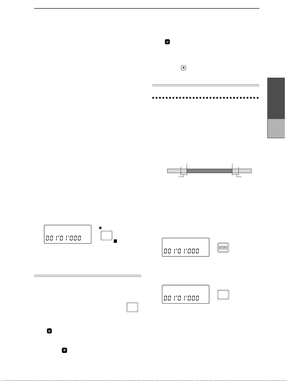
10. Combining multiple
tracks into one or two
tracks (Bounce)
The performance of multiple tracks can be combined into one or two tracks, freeing the original
tracks for additional recording. This operation is
called “track bouncing” or “ping pong recording”.
This can be used when you wish to record more
than 8 tracks, etc.
As an example, we will show how you can combine the performances of tracks 1–5 to track 6. We
will also explain how you can combine tracks 1–5
to tracks 7 and 8 in stereo.
Track 1
Track 2
Track 3
Track 4
Track 5
■ Playback track and recording track settings
1 Press the [REC SELECT] key several
times to select INPUT 1/2 + MASTER
(both indicators lit). With a setting of
INPUT 1/2 + MASTER, you can use
the master bus as the input for recording.
2 Press the [TRACK STATUS] keys for tracks 1–5
several times to set each one to PLAY (indicator lit
green), to select these as playback tracks. Press the
track 6 [TRACK STATUS] key several times to
select REC (ANALOG) (indicator blinking red), to
select it as the recording track.
Track 6 (1+2+3+4+5)
INPUT 1/2
MASTER
DIGITAL I
REC
SELECT
and 8, rotate the [PAN] knobs of tracks 1–5 to place
each track at the desired stereo location.
Operation
Chapter 2
Recording
1
L
lit green
5
L
6
R
blinking red
✧ If you are combining the other tracks to tracks 7
and 8 in stereo, press the track 7/8 [TRACK STATUS] key several times to select REC (ANALOG)
(indicator blinking red).
3 Track 6 (the recording track) uses the “R” bus
(printed on the [TRACK STATUS] key). Rotate the
[PAN] knobs of tracks 1–5 to the far right position
(R), so that their sound will be sent to the right
channel.
When bouncing to a single track, be sure to set the
[PAN] knobs of the bounce source tracks to match
the indication of either “L” or “R” shown above
the [TRACK STATUS] key of the bounce destination track.
PAN
LR
1
PAN
LR
5
✧ If you are combining tracks 1–5 in stereo to tracks 7
Page 17

20
■ Adjusting the playback level and recording
level
4 Press the [PLAY] key to begin playback.
5 Raise [CHANNEL] faders 1–5 to adjust the play-
back level of each track. (Refer to p.27)
6 Raise the [MASTER] fader to adjust the recording
level to track 6.
The master level meter R will show the recording
level to track 6.
✧ If you are combining the tracks in stereo to tracks 7
and 8, the [MASTER] fader will adjust the recording level of tracks 7/8, and the master level meters
L/R will show the recording level.
7 Since [CHANNEL] fader 6 will adjust the input
level to INPUT 1, you can record an additional
input sound while you bounce the other tracks. In
this case, raise [CHANNEL] fader 6 to adjust the
input sound. If you are not recording an input
sound, either lower the fader.
✧ If you are combining the tracks in stereo to tracks 7
and 8, [CHANNEL] fader 7/8 will adjust the input
level.
8 For tracks 7/8 (which are not being recorded),
either turn down [CHANNEL] fader 7/8 or press
the [TRACK STATUS] key several times to select
MUTE (indicator off).
✧ If you are combining the tracks in stereo to tracks 7
and 8, track 6 will not be recorded. Either turn
down [CHANNEL] fader 6 or select MUTE.
■ Listening to the recor ded perf ormance (Play-
back)
12 Press the [TRACK STATUS] key to set tracks 1–5 to
MUTE (indicator off), and set track 6 to PLAY
(indicator lit green). Then raise [CHANNEL] fader
6 to adjust the playback level.
✧ If you have combined tracks in stereo to tracks 7/8,
set the [TRACK ST ATUS] of tracks 7/8 to PLAY, set
all others to MUTE, and raise the [CHANNEL]
fader 7/8 to adjust the playback level.
13 Move the current time location to a point earlier
than where you began recording, and press the
[PLAY] key to begin playback. Press the [STOP]
key to stop playback. (Refer to “■ Listening to the
recorded performance (Playback)”, p.11)
■ Applying EQ and effects while you record
9 Apply EQ to tracks 1–5 as desired while you
record. (Refer to p.28)
10 As desired, apply effects to tracks 1–5 and record
them. For details on applying effects refer to “3.
Applying effects to the playback sound” (p.21) or
“2. Applying the internal effect during mixdown”
(p.28)
When [EFFECT ASSIGN] is set to MASTER (Send
Type), the signal sent to the effect will be monaural, so there will be cases in which a stereo effect
cannot be obtained even if a stereo input type
effect is selected.
■ Starting and stopping recording
11 Press the [REC] key, and then press the [PLAY] key
to begin recording. To stop recording, press the
[STOP] key. (Refer to “■ Starting and stopping
recording”, p.11)
Page 18

21
11. Listening to the metronome while you recor d
The D8 contains a wide variety of metronome patterns for each time signature. (Refer to “Metronome pattern list”) If you have an idea for a song,
you can record immediately using the built-in metronome without having to connect a rhythm
machine etc.
The sound of the metronome will not be recorded.
The metronome sound will be output together
with the master audio output from the OUTPUT
L·R jacks.
■ Turning the metronome on/off
1 Press the [METRONOME] key to turn the metro-
nome ON (indicator lit).
When you record or playback, the metronome will
sound. (Refer to “■ Sounding the metronome during playback and recording”)
METRO
NOME
E
■ Setting the tempo and time signature
6 Press the [TEMPO] key (press the [EDIT] key to
make the indicator go off) to access the display
such as “0:120|4/4” which shows the tempo and
time signature. (The metronome will sound.)
0:120|4/4œ
7 Rotate the [VALUE] dial to select 0 at the left edge.
0 is the basic tempo that is located at the beginning
of the song.
8 Press the [ ] key to move the cursor to the tempo
value, and rotate the [VALUE] dial to set the
tempo. In the same way, press the [ ] key to move
the cursor to the time signature, and rotate the
[VALUE] dial to set the time signature.
✧ You can press the [METRONOME] key to turn the
metronome sound on/off.
TEMPO
E
■ Selecting the metronome pattern
9 Press the [ ] key, and then rotate the [VALUE]
dial to select the metronome pattern. (Refer to
“Metronome pattern list”)
Operation
Chapter 2
Playback
■ Adjusting the metronome volume
2 Press the [EDIT] key (the metronome will sound,
and the indicator will light), and then press the
[METRONOME] key to access the “MetVol” display. If the display reads “MetMod”, press the
[METRONOME] key once again.
MetVol:080
✧ Also, instead of pressing the [EDIT] key, you can
press the [TEMPO] key several times to make the
display read “MetVol” and adjust the metronome
volume.
3 Rotate the [VALUE] dial to adjust an appropriate
volume.
EDIT
METRO
NOME
E
■ Sounding the metronome during playback
and recording
4 Press the [METRONOME] key once again, to
access the “MetMod” display.
MetMod:P+R
5 Rotate the [VALUE] dial to select P+R
(Play+Recording). With this setting, the metronome will sound during playback and during
recording. With a setting of Rec, the metronome
will sound only during recording.
METRO
NOME
E
œ:Metro4 œ
✧ You can change the time signature, tempo or met-
ronome pattern during the song. (Refer to “Tempo
map settings”, p.36)
■ Connecting the input device and adjusting
the level
10 As explained in “■ Connecting the input device
and adjusting the level” (p.11, p.12), connect the
input device and adjust the level.
■ Starting and stopping recording
11 Press the [REC] key and a count will begin. Press
the [PLAY] key to begin recording, and the selected
metronome sound will be heard. Play along with
the metronome sound. (Refer to “■ Starting and
stopping recording”, p.11)
■ Listening to the recor ded perf ormance (Play-
back)
12 Move the current time location to a point earlier
than where you began recording. Then set the
[TRACK STATUS] of the recorded track to PLAY,
and press the [PLAY] key to playback. Press the
[STOP] key to stop. (Refer to “■ Listening to the
recorded performance (Playback)”, p.11)
Page 19
22
12. Trigger recording
n
You can use the input sound as a trigger that will
start recording. The D8 will begin recording at the
moment that sound is input.
Playback
STEP4
This section explains the variety of playback methods provided by the D8.
■ Connecting the input device and adjusting
the level
1 As explained in “■ Connecting the input device
and adjusting the level” (p.11, p.12), specify the
track to be recorded.
■ Preparations for trigger recording
2 Press the [TRIGGER] key to turn the Trigger func-
tion on (indicator lit).
TRIGGER
E
3 Move to the time location where you wish to begin
recording.
4 Press the [REC] key to enter record ready mode
(indicator blinking).
■ Begin trigger recording
5 Begin playing. When the input exceeds the thresh-
old level, recording will start.
If the Pre Trigger Time has been set to a value other
than 000 mS, recording will begin at the specified
time earlier than when triggering occurred, and
any previously recorded sound during that interval will be erased (refer to p.53).
6 When you finish your performance, press the
[STOP] key to stop recording.
■ Listening to the recor ded perf ormance (Play-
back)
7 Move the current time location to a point earlier
than where you began recording. Then set the
[TRACK STATUS] of the recorded track to PLAY,
and press the [PLAY] key to playback. Press the
[STOP] key to stop. (Refer to “■ Listening to the
recorded performance (Playback)”, p.11)
■ Adjusting the threshold level
If the location where recording begins is not appropriate, you can change the settings of EDIT TRIGGER P1 (refer to p.53) to adjust the input level
which will start recording.
1. Playback
Here we will explain the basic method of playback.
Refer also to the later section “Adjusting and registering mixer settings”.
■ Selecting the playback tracks
1 Press the [TRACK STATUS] keys
for tracks which contain recorded
material, to select PLAY (indicator
lit green).
lit gree
1
L
■ Move the current time location to the begin-
ning of the song
2 Hold down the [STOP] key and press the [REW]
key. If you wish to move to another location in the
song, refer to “Moving the current time”.
■ Starting and ending playback
3 Press the [PLA Y] key to begin playback (indicator lit).
4 Press the [STOP] key to stop playback (the [PLAY]
indicator will go off).
✧ You can start/stop playback by pressing a foot
switch <sold separately> (refer to p.47).
2. Playing a specified area of a
song once or repeatedly
By using the “Auto Play function” which plays the
IN–OUT area of the song once, or the “Auto
Repeat function” which repeatedly plays back the
IN–OUT area, you can playback a specified area. It
is convenient to use these functions in conjunction
with Auto Punch In/Out recording.
1 Press the [TRACK STATUS] key several times for
each track that you wish to playback, to select
PLAY (indicator lit green).
2 Store the IN and OUT locations of the desired area
for playback. (Refer to “Locate points (LOC1,
LOC2, LOC3)”, p.25)
3 If you wish to playback the IN–OUT
area once, press the [PLAY MODE]
key several times to make the “ ”
symbol appear in the display.
If you wish to repeatedly playback the IN–OUT
area, press the [PLAY MODE] key several times to
make the “ ” symbol appear in the display.
4 When “ ” is displayed, pressing the [PLAY] key
will cause the IN–OUT area to playback, and then
stop automatically.
When “ ” is displayed, pressing the [PLAY] key
will cause the IN–OUT area to playback repeatedly.
Playback will stop when you press the [STOP] key.
PLAY
MODE
E
Page 20
23
3. Applying an effect to
4. Applying an external effect to
the playback sound
■ Selecting the tracks for playback
1 Press the [TRACK STATUS] key to select PLAY
(indicator lit green).
lit green
1
L
■ Specifying the location at which you wish to
insert the effect
2 Press the [EFFECT ASSIGN] key
several times to select MASTER
(Send Type) (indicator lit). When
MASTER (Send Type) is selected,
the sound from the Send bus will be
sent to the internal effect, and then
output to the master bus.
Pb T rack
3 Press the [PLAY] key to begin playback.
■ Sending the playback sound to the effect
4 Press the [EFFECT SEND] key several times for each
track to which you wish to apply the effect to access
the “Snd✽” display (✽ is the channel number).
Snd1 :080
2
R
[EQ]
HEQ LEQ
FADER
Snd
EFFECT
SEND
Effect
INPUT 1/2
MASTER
EFFECT
ASSIGN
OUTPUT
E
the playback sound
1 Connect the INPUT jack of an external effect device
to the D8’s AUX OUT jack, and the OUTPUT jacks
of the external effect device to the D8’s AUX IN
jacks. If the external effect has stereo output, connect
its OUT L/R jacks to the D8’s AUX IN L/R jacks.
External effect device
PROGRAM
WRITE
EDIT
ACHAIN/EFFECT
DISPLAY
UTILITY
SELECT
OUTPUT
LR
2 Press the [EFFECT ASSIGN] key several times to
select MASTER (Send Type) (indicator lit).
When INPUT 1/2 or MASTER (Global Type) is
selected, the input from the AUX IN jacks is
ignored.
3 Press the [PLAY] key to begin playback.
■ Sending the playback sound to the external
effect
4 Press the [EFFECT SEND] key several times for
each playback track where you wish to apply the
external effect, to access the “Aux✽” display (✽ is
the channel number).
Aux1 :100
5 Rotate the [VALUE] dial to adjust the amount that
will be sent to the external effect.
Be careful that the input of the external effect does
not clip.
EFFECT
SEND
BCDEF
INDIVIDPROGRAM BYPASS
[BYPASS]
INPUT
POWER
CARD
Operation
Chapter 2
Moving
and storing
time locations
5 Rotate the [VALUE] dial to adjust the amount that
will be sent to the effect.
Be careful not to make the effect (“E”) level meter
light all the way to CLIP.
■ Selecting an effect program
■ Adjusting the return level and return balance
from the effect
■ Editing an effect
■ Saving an effect program
6 As explained in “■ Selecting the effect program” –
“■ Saving the effect program” (p.13, p.15), save the
desired settings for the effect program.
When [EFFECT ASSIGN] is set to MASTER (Send
Type), the signal sent to the effect will be monaural, so there will be cases in which a stereo effect
cannot be obtained even if a stereo input type
effect is selected.
■ Adjusting the input level and input balance
from the external effect
6 Press the [EDIT] key, and then press the [EFFECT
ASSIGN] key several times to access the “AuxRet”
display (external input level).
INPUT 1/2
AuxRet:080
EDIT
MASTER
EFFECT
ASSIGN
E
7 Rotate the [VALUE] dial to adjust the return level
from the external effect.
8 Press the [EFFECT ASSIGN] key to access the
“AuxBal” display (external input balance).
INPUT 1/2
AuxBal:CNT
MASTER
EFFECT
ASSIGN
E
9 Rotate the [VALUE] dial to adjust the return bal-
ance from the effect.
Page 21
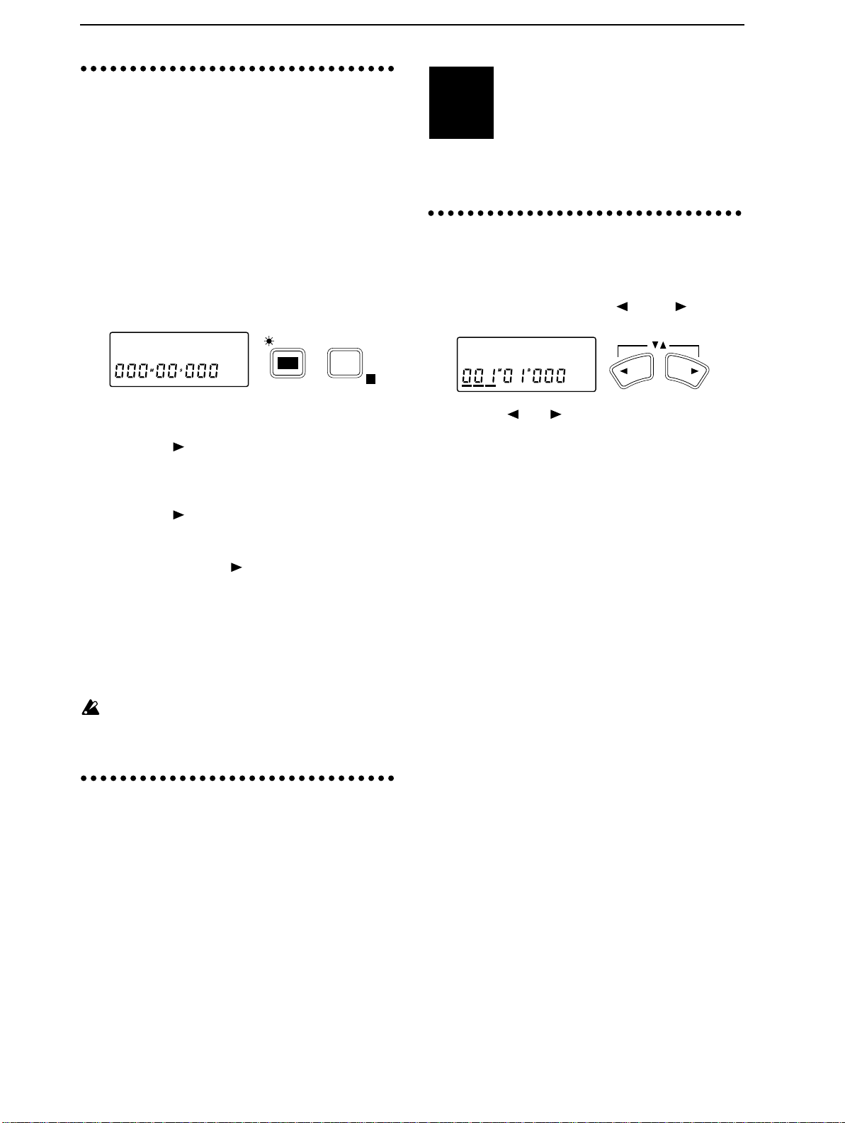
24
5. Program playback of
songs
You can enable two or more songs to playback in a
specified order. This can be used to playback a
medley of songs, or when you wish to record consecutive mixdowns of songs to DAT or MD. Program Play can be performed even across multiple
drives. As an example, we will explain how to
playback songs in the order of song number I
(internal drive) 01
1 Press the [EDIT] key, and then press the [PLAY
MODE] key several times to access the “P✽✽” display (✽✽ is the sequence of playback).
→I02→A (SCSI ID 0) 05.
Moving and storing
STEP5
explains how you can store a specific time location for
instant recall.
1. Moving the current time
■ Using the location counter to move
1 Simultaneously press the [ ] and [ ] keys to
move the cursor below the location counter.
time locations
This section explains how to move
between time locations in a song. It also
P01:I01 œ
2 Rotate the [VALUE] dial to select the first step in
the playback sequence; P01.
3 Press the [ ] key, and then rotate the [VALUE]
dial to select the drive from which the song will be
played back. In this example, select the internal
drive I.
4 Press the [ ] key, and then rotate the [VALUE]
dial to select the song which will be played back as
the first song. In this example, select 01.
5 Press and hold the [ ] key for approximately 1
second to finalize the first song for playback. When
this is finalized, the “?” will disappear.
6 Rotate the [VALUE] dial to select the second song
for playback. Referring to steps 3–5, set P02 to
song I02, and set P03 to song A05.
7 Press the [PLAY] key, and the songs will playback
in the specified sequence, starting with I01.
Program playback is available only when you are
in this page. Also, the specified sequence of songs
will be canceled when you leave this page.
EDIT
PLAY
MODE
E
E
6. Switching scenes during playback
A set of mixer settings that have been stored is
called a “scene”, and scenes can be switched as
time elapses during playback. (Refer to p.29)
01:KORG1 œ
YESNO
2 Use the [ ] or [ ] keys to move the cursor to the
unit of time that you wish to change (measure
B
, 1/96th beat, Mark etc.)*. For details on
beat
Marks, refer to p.26.
3 Rotate the dial to move the time location.
Rotating the dial toward the right will increase the
time, and rotating it toward the left will decrease
the time.
* You can change the units of time that appear in the
display. Four methods of display can be selected.
(Refer to “5. DISPLAY MODE”, p.51)
M
■ Using the [STOP], [REW] and [FF] keys to
move
Moving backward
✧ Press the [REW] key to move toward the beginning
of the song. If you hold down the key, you will
move continuously. You can also move during
playback.
Moving forward
✧ Press the [FF] key to move toward the end of the
song. If you hold down the key, you will move continuously. You can also move during playback.
Moving to the beginning of the song/Moving to the
beginning of the previous song
✧ If the current time is in the middle of the song, you
can hold down the [STOP] key and press the
[REW] key to move to the beginning of the song.
If the current time is at the beginning of the song,
you can hold down the [STOP] key and press the
[REW] key to select the song of the previous number, and move to its beginning.
Moving to the beginning of the next song/Creating a new song
✧ If you hold down the [STOP] key and press the
[FF] key, you will select the song of the following
number, and move to its beginning. If the following number does not contain a song, a new song
will be created for that number. (Refer to p.10)
,
Page 22
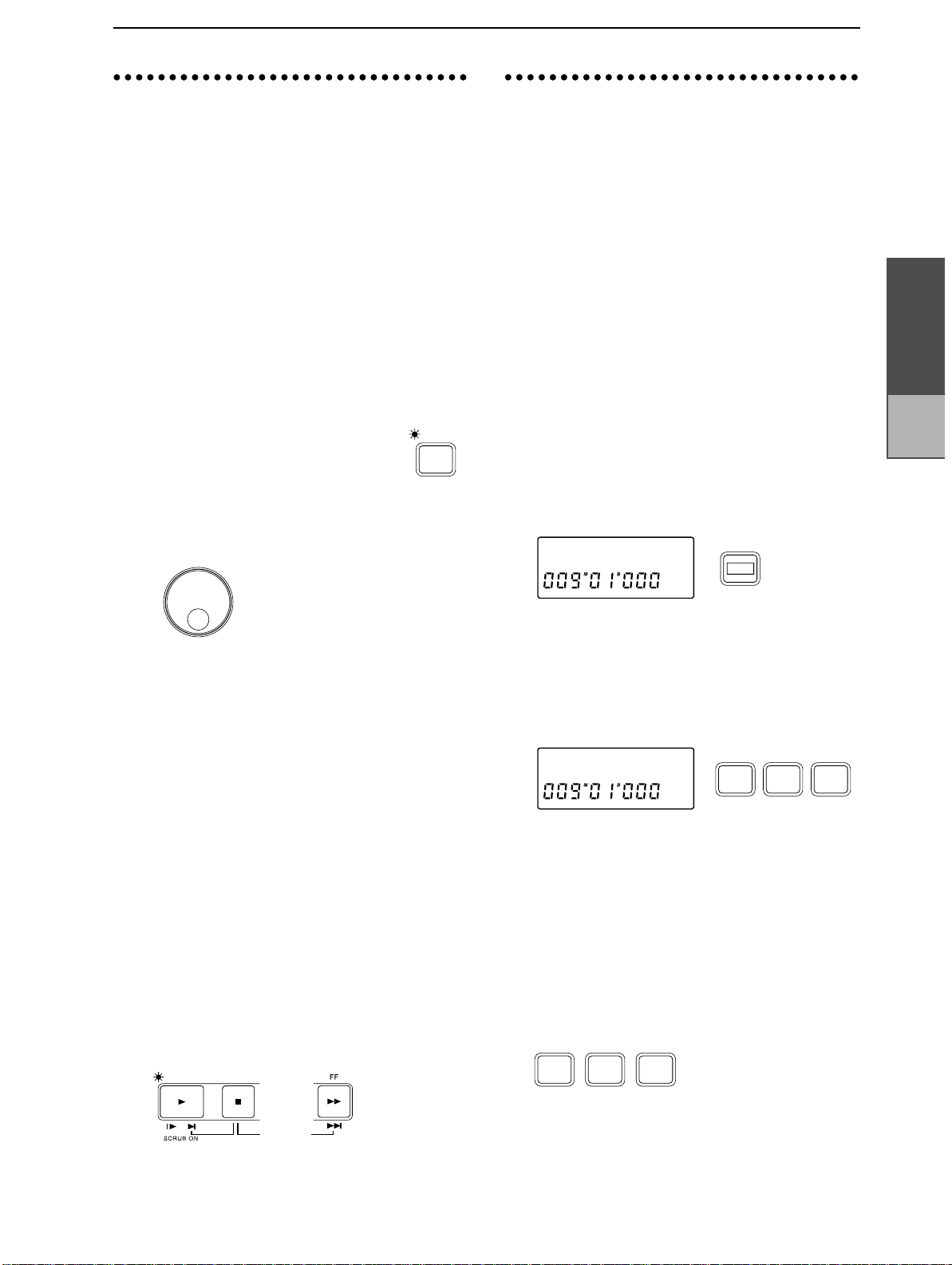
25
2. Finding a precise time
3. Locate points
location
If you wish to find the exact time location at which
a sound begins, or when setting locate points or
storing marks, you can use the Scrub function or
the Play From/Play To functions to find and select
time locations more accurately.
■ The Scrub function
On the D8 you can perform Scrubbing just as on an
open reel tape recorder. By rotating the [VALUE] dial
you can playback the song to accurately find a desired
moment in time. This is called the “Scrub” function.
1 Set the [TRACK STATUS] to PLAY (indicator lit
green) for the track that you wish to scrub.
2 Press the [SCRUB] key to turn on the
Scrub function (indicator lit).
3 Rotate the [VALUE] dial to find the precise location
while you listen to the sound. The track will playback linked with the movement of the [VALUE]
dial.
SCRUB
(LOC1, LOC2, LOC3)
You can store a specific time location, and then
move instantly to that location at any time. For
each song, you can store three “Locate” points, and
also one hundred “Mark” points. In addition to
being used to move instantly to a desired time,
Locate points are also used as the in/out times for
Auto Punch In/Out recording, and to specify the
in/out/to times for track editing operations. (Refer
to p.31)
■ Storing a Locate point
Here’s how to use the Locate function to store the
current time. A time that has been stored in this
way is called a “Locate point”.
1 Move the current time to the location that you wish
to store. (Refer to “1. Moving the current time”,
p.24)
2 Press the [STORE] key to prepare to store the time.
The display will indicate “Store”.
Storeø
STORE
Operation
Chapter 2
Adjusting
and storing mixer
settings
At this time, the level meter will show the prefader volume level of each track.
When the dial is not moving, the volume level at
that time will be displayed.
■ Play From/Play To/Slow Play functions
1 Set [TRACK STATUS] to PLAY (indicator lit green)
for the track that you wish to scrub.
2 Press the [SCRUB] key to turn on the Scrub func-
tion (indicator lit).
3 Press the [PLA Y] key, and playback will occur from
the current time for two seconds, and will then
stop. Then you will automatically return to the
location at which playback began (Play From).
Hold down the [STOP] key and press the [PLAY]
key, and the sound will playback from approximately two seconds before the current time, and
will then stop (Play To).
Press the [FF] key, and the sound will playback
from the current time at half-speed, and will stop
and automatically return to the playback start location when you press the [STOP] key (Slow Play).
PLAY STOP
3 Press the key [IN/LOC 1], [OUT/LOC 2] or [TO/
LOC 3] for which you wish to store the current
time. The display will indicate “Store
→✽✽✽ (store
destination In, Out, To)”, and the current time will
be stored to the key.
Release the key, and the previous page will reappear.
Store˘In
IN /
LOC 1
OUT /
LOC 2
TO /
LOC 3
Storing during playback or recording
While you are playing or recording a song, you can
use the above steps 2 and following to store a
locate point. The time location at the moment that
you press the [IN/LOC 1], [OUT/LOC 2] or [TO/
LOC 3] key will be stored.
■ Moving to a Locate point
✧ When you press a [IN/LOC 1], [OUT/LOC 2] or
[TO/LOC 3] key that you have previously stored,
you will move to the stored time.
IN /
LOC 1
OUT /
LOC 2
TO /
LOC 3
✧ It is convenient to use the Scrub function or Slow Play
to find the precise time, and then to use the Play
From/Play To functions to verify that time location.
Page 23
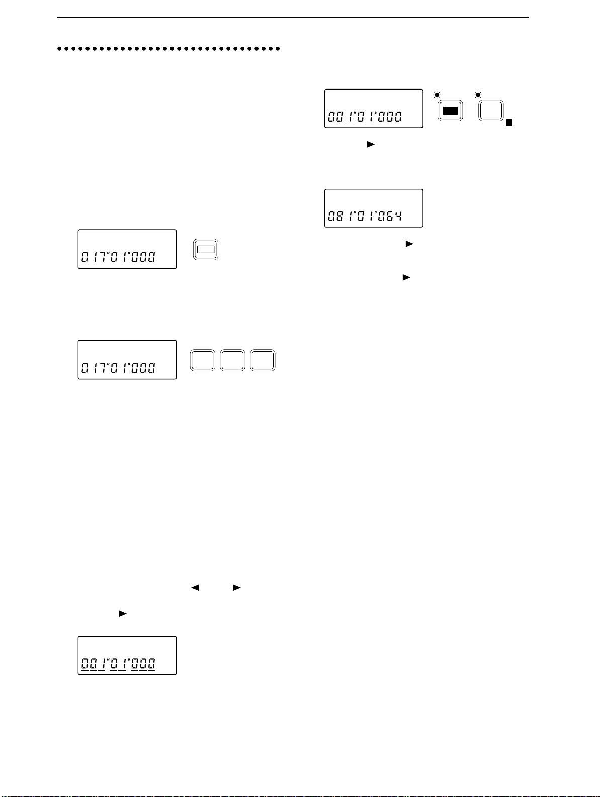
26
4. Mark points
You can store a desired time location and move
instantly to that time. Up to one hundred Mark
points can be stored in each song.
■ Deleting a Mark point
1 Press the [EDIT] key, and then press the [SYSTEM]
key several times to access the “Mark” display.
Mark ˙
EDIT
SYSTEM
E
■ Storing a Mark point
Here’s how to use the Mark function to store the
current time. A time location that has been stored
in this way is called a “Mark point”.
1 Move the current time to the desired location.
2 Press the [STORE] key twice to prepare for storing.
The display will indicate “Mark”.
Markø
3 Press any one of the [IN/LOC 1], [OUT/LOC 2] or
[TO/LOC 3] keys. The display will indicate
“Mark
→M✽✽✽ (stored number)”, and the current
time will be stored as a Mark point. Release the
key, and the previous page will reappear.
Mark˘M001
Storing during playback or recording
During playback or recording, you can perform the
above steps 2 and following to store a Mark point.
The time location at the instant you press the [IN/
LOC 1], [OUT/LOC 2] or [TO/LOC 3] key will be
stored.
Storing using a foot switch
1 Press the [SYSTEM] key several times to access the
“Fsw” display, and then rotate the [VALUE] dial to
select Mark.
2 A Mark point will be stored at the instant you
press the foot switch. You can store Mark points
during playback or during recording.
STORE
IN /
LOC 1
OUT /
LOC 2
TO /
LOC 3
2 Press the [ ] key to access the “Del” display, and
rotate the [VALUE] dial to select the Mark that you
wish to delete. If you select All, all Mark points
will be deleted.
DeløM004 ?
3 Press and hold the [ ] key for approximately one
second to execute the operation. When the Mark
has been deleted, the display will indicate “Completed”. Press the [ ] key to restore the previous
display.
■ Moving to a Mark point
1 Simultaneously press the [ ] and [ ] keys to
move the cursor below the location counter.
2 Press the [ ] key several times so that the cursor is
displayed below the entire location counter.
01:SngNam
3 Rotate the [VALUE] dial to select the Mark points
that have been stored, and move the current time.
Page 24

27
Adjusting and storing
STEP6
input/recording/playback for each channel, to create
the desired overall balance of sound. This process is
known as “mixdown”.
Mixer settings can also be registered as a “scene”.
Scenes can be selected as time passes during playback,
or recalled as general-purpose settings.
1. Pairing settings
You can group the settings of adjacent odd/even
mixer channels (1-2, 3-4, 5-6), so that changes made
to the values of one channel will be reflected by
both channels. This is referred to as “pairing”. This
is convenient when you are mixing tracks that
were recorded in stereo.
Pairing applies to the settings of the [TRACK STATUS] keys, high EQ “HEQ”, low EQ “LEQ”, effect
send “Snd”, Aux send “Aux”, the [PAN] knobs and
the [CHANNEL] faders.
Of these, you can specify for each setting other
than the [TRACK STATUS] keys and the [CHANNEL] faders whether or not the setting will be
paired when pairing is turned on.
■ Pairing on/off
1 To turn pairing on, simultaneously press the
[EFFECT SEND] keys for the desired pair of adjacent odd/even channels (1-2, 3-4, 5-6).
EFFECT
When pairing is on, parameters for which pairing
is enabled can be operated as follows.
[TRACK STATUS] keys, “HEQ”, “LEQ”, “Snd”
and “Aux” can be set from either odd or even
channel.
[CHANNEL] faders and [PAN] knobs (pan will
function as the left/right balance adjustment when
paired) are operated from the odd-numbered channel (1, 3, 5). Adjustments made to the even-numbered channel will be ignored.
When pairing is on, adjusting the EQ etc. will
cause the display to appear as follows.
mixer settings
This section explains how you can adjust
the volume, tone and pan etc. of the
PAIR ON / OFF
EFFECT
SEND
SEND
■ Enabling parameters for pairing
For the [PAN] knobs, “Snd”, “Aux” and “EQ”, you
can specify whether or not pairing will be enabled
for each parameter. This setting is common to the
entire song.
1 Press the [EDIT] key, and then press the [SYSTEM]
key several times (the indicator will light) to access
the “ChPairSw” display.
ChPairSw ˙
SYSTEM
E
2 Press the [ ] key to move the cursor, and press the
[SYSTEM] key to select the item for which you
wish to enable/disable pairing.
EQ :oœ
3 Rotate the [VALUE] dial to enable (o) or disable (-)
pairing.
2. Adjusting the volume of
each channel
You can adjust the input/recording/playback volume of each channel. The available range extends
from OFF to unity gain ( )* and an additional +12
dB of gain. Normally you will leave the faders set
at unity gain, and rather than raising the fader for
low-volume channels, it is best to make adjustments by lowering the other faders.
* Unity gain refers to the state at which the audio
signal does not change, and is the optimal level for
the sound.
✧ To adjust the volume, raise or lower
the [CHANNEL] fader of the corresponding channel.
When pairing is on, use the odd-numbered channel to make adjustments.
This parameter can be stored in a
scene.
When the input monitor (refer to p.47) is set to
AUTO, the faders of tracks whose [TRACK STATUS] is set to REC will affect only the input sound,
and will not affect the playback sound (refer to
p.58).
1
Operation
Chapter 2
Adjusting
and storing mixer
settings
HEQ1-2:+00
2 To turn pairing off, simultaneously press the
[EFFECT SEND] keys of the adjacent odd/even
channels.
Page 25

28
3. Adjusting the stereo
location
You can adjust the stereo location of the sound of
each channel. Normally, vocals and bass etc. are
placed in the middle, guitar at either left or right,
and piano at the opposite side from the guitar.
✧ Rotate the [PAN] knob or [BALANCE] knob to
adjust the stereo location of each channel. Rotating
the [PAN] knobs of channels 1–6 toward the left
will move the sound to the left, and rotating them
toward the right will move the sound to the right.
The [BALANCE] knob of channels 7/8 adjusts the
left/right balance. When pairing is on, the [PAN]
knobs will adjust the left/right balance, and only
the [PAN] knobs of the odd-numbered channels
are used.
PAN
LR
1
This parameter can be stored in a scene.
LR
PAN
6
BALANCE
LR
7/8
■ Adjusting the Low EQ
The low EQ lets you cut/boost the 100 Hz frequency range over a range of -15–+15 dB.
1 Press the [EQ] key of the channel whose tone you
wish to adjust, to access the “LEQ✽” display (✽ is
the channel number). “HEQ” and “LEQ” will alternate each time you press the key.
LEQ1 :+00
2 Rotate the [VALUE] dial to adjust the EQ gain.
When the input monitor (refer to p.47) is set to
AUTO, the EQ of tracks whose [TRACK STATUS]
is set to REC will affect only the input sound, and
will not affect the playback sound (refer to p.58).
Also, after recording with EQ applied, if you leave
the EQ settings as they are and playback with
[TRACK STATUS] set to PLAY, be aware that the
EQ will be applied twice (refer to p.58).
EQ
5. Adjusting the Effect
4. Using the EQ to adjust
the tone
You can use the equalizer to adjust the tonal character of each channel. If you adjust the tone of the
input signal as you record it, the sound will be
recorded that way.
This can be used to cut the high frequency range
which sometimes contains obtrusive hiss noise, or
to cut/boost the low range or high range to adjust
the tonality.
Normally, you will use EQ to give the sound more
clarity and definition. However if EQ settings are
excessively high, such as when the maximum
amount of boost is used, the overall mix will be
unbalanced, and the sound can be fatiguing. It is
recommended that EQ be used in the “cut” direction as well, and that you use no more boost/cut
than necessary.
■ Adjusting the High EQ
The high EQ lets you cut/boost the 10 kHz frequency range over a range of -15–+15 dB.
1 Press the [EQ] key of the channel whose tone you
wish to adjust, to access the “HEQ✽” display (✽ is
the channel number). “HEQ” and “LEQ” will alternate each time you press the key.
Send, AUX Send and
Track Status
Effect Send (“Snd”) adjusts the amount of sound
that is sent from each channel to the internal effect
(refer to p.14 and p.23).
AUX Send (“Aux”) adjusts the amount of sound
that is sent from each channel to AUX OUT. (Refer
to p.23)
Track Status ([TRACK STATUS]) determines
whether each track can be recorded or played back,
or will be muted.
HEQ1 :+00
2 Rotate the [VALUE] dial to adjust the EQ gain.
EQ
Page 26

29
6. Scene
Mixer settings can be stored as a “scene”, and
scenes can be recalled automatically as playback
progresses, or recalled whenever desired as general-purpose mixer setups. Up to 20 scenes can be
stored in each song.
■ Storing a scene
For each channel, the volume level specified by the
[CHANNEL] fader, the stereo location set by the
[PAN] knob or [BALANCE] knob, the high EQ
“HEQ” and low EQ “LEQ” settings, the effect send
level “Snd” and the AUX send level “Aux” can be
stored in a scene.
1 Move the current time to the location where you
wish to store the scene.
2 Adjust the mixer settings at that time location.
3 Press the [STORE] key to access the “Store” dis-
play.
Store˘
4 Press the [SCENE] key to access the “Store
display (✽✽ is the scene number into which the settings will be stored), and the mixer settings will be
stored as a scene.
Scene numbers will be assigned automatically,
beginning from the lowest vacant number.
Store˘S01
READ
SCENE
Storing a scene during playback or recording
During playback or recording, you can perform the
above steps 3 and following to store a scene.
In this case, the time location and mixer settings at
the moment you press the [SCENE] key will be
stored as the scene.
→S✽✽”
E
■ Switching scenes during a song
Scenes that have been stored can switch automatically as playback progresses.
1 Refer to “■ Storing a scene”, and register a scene at
the desired times in the song.
2 Press the [SCENE] key to select Scene Read ON
(indicator lit). This setting will alternate on/off
each time the key is pressed.
READ
SCENE
E
3 Move to the location from which you wish to play-
back, and press the [PLAY] key to begin playback.
(Refer to “1. Playback”, p.22)
When the stored time arrives, the scene will change
automatically.
■ Recalling a scene
1 If the [SCENE] indicator is lit, press the [SCENE]
key to turn Scene Read OFF (indicator off).
READ
SCENE
E
2 After pressing the [EDIT] key, press the [SCENE]
key to access the “S✽✽:Fader” display (✽✽ is the
scene number).
S01:Fader
EDIT
READ
SCENE
E
3 Rotate the [VALUE] dial to select the scene num-
ber. The selected scene will be recalled.
■ Deleting a scene
1 Press the [EDIT] key, and then press the [SCENE]
key several times to access the “Del
(✽✽ is the scene number).
Del˘S01 ?
→S✽✽” display
EDIT
READ
SCENE
E
Operation
Chapter 2
Track editing
2 Rotate the [VALUE] dial to select the scene number
(S01–S20) that you wish to delete. If you select All,
all scenes will be deleted.
3 Press and hold the [ ] key for approximately one
second to delete the scene. When the data has been
deleted, the display will indicate “Completed”.
Press the [ ] key to restore the display.
Page 27

30
Mixdown
Master
STEP7
1. Recording a master
■ Listening to the completed song
1 Use the [CHANNEL] faders to adjust the volume
level of each channel.
2 Use the [PAN] knobs and [BALANCE] knobs to
adjust the stereo location of each track.
3 Press the [EQ] key for each track and use the
[VALUE] dial to adjust the tone.
4 Adjust the effects. For effects which are particu-
larly appropriate during mixdown, refer to “2.
Applying the effect during mixdown”.
■ Connect an external recording device and
record
5 If you will be making an analog recording, use
RCA phono cables to connect the analog LINE IN
jacks of your cassette recorder, DAT recorder or
MD recorder etc. to the OUTPUT L·R jacks of the
D8.
A song that you have completed by recording tracks and mixing can be recorded on
an external two-channel recorder such as a
cassette tape recorder, DAT recor der or MD
recorder. This process is referred to as
“mixdown”.
tape (Mixdown)
Cassette tape
LINE IN L
recorder etc.
2. Applying an effect during mixdown
During mixdown, you can apply effects such as
limiter (an effect which smoothes out the volume
of the input signal) or compressor (an effect which
compresses the input signal to give the sound more
consistency and punch) so the sound that is output
and recorded on the external recorder will be consistent in volume.
■ Specifying the location at which the effect
will be inserted
1 Press the [EFFECT ASSIGN] key several times to
select MASTER (Global Type) (indicator blinking).
blinking
INPUT 1/2
MASTER
EFFECT
ASSIGN
E
LR
Effect
Master
FADER
OUTPUT
Pb T rack
PAN
2 Playback the song while you adjust the effect set-
tings described below.
■ Selecting an effect program
3 As described in “■ Selecting the effect program”
(p.13), select an effect program such as “DY1:
LIMIT” (TOTAL LIMITER)”, etc.
œ
R
If you will be making a digital recording, use an
optical cable to connect the DIGITAL IN connector
of your DAT recorder or MD recorder to the DIGITAL OUT connector of the D8.
DAT / MD recorder etc.
DIGITAL IN
6 Playback the D8, and adjust the recording level on
your cassette tape recorder, DAT recorder or MD
recorder etc. Then return the D8 to the beginning
of the song, and record the mixdown on your
recorder.
■ Editing the effect
■ Saving the effect program
4 As described in “■ Editing the effect” – “■ Saving
the effect program” (p.13), adjust the desired settings for the effect program.
Page 28

31
Track editing
STEP8
1. Storing IN, OUT and TO
In order to edit track data, you must store the time
locations at which editing will be performed. As
explained in “3. Locate points (LOC1, LOC2,
LOC3)” (p.25), LOC1 functions as the IN time,
LOC2 as the OUT time, and LOC3 as the TO time.
1 Change the current time location to the point that
you wish to store as the IN time. (Refer to “1. Moving the current time”, p.24)
The IN time will function as follows for each editing operation.
Copy Track: the beginning of the source data
Insert Track: the location at which the blank will
Erase Track: the location at which erasure will
Delete Track: the location at which deletion will
Swap Track: the location at which the exchange
2 Press the [STORE] key to access the “Store” dis-
play, and then press the [IN/LOC 1] key to store
the IN time.
3 Change the current time location to the point that
you wish to store as the OUT time.
The OUT time will function as follows for each
editing operation.
Copy Track: the end of the source data that will
Insert Track: the location at which the inserted
Erase Track: the location at which erasure will
Delete Track: the location at which deletion will
Swap Track: the location at which the exchange
4 Press the [STORE] key to access the “Store” dis-
play, and then press the [OUT/LOC 2] key to store
the OUT time.
5 Change the current time location to the point that
you wish to store as the TO time.
The TO time needs to be stored only if you are
using the Copy Track operation, and will be the
time at which the data will be placed in the copy
destination track.
6 Press the [STORE] key to access the “Store” dis-
play, and press the [TO/LOC 3] key to store the TO
time.
This section explains the editing operations
(copy, insert blank, delete, exchange etc.) that
can be performed on tracks.
times
that will be copied
be inserted
begin
begin
will begin
be copied
blank will end
end
end
will end
2. Copying track data
(Track Copy)
This operation copies a portion (IN–OUT) of a
recorded track to another location (TO). You can
copy data from a single track or from multiple
tracks simultaneously. You can also copy the data
more than one time. By using the clipboard, you
can copy data to another song.
For example, you could use this to repeatedly copy
a phrase of several measures, such as a drum pattern, or record a favorite phrase in one track, and
use it by copying it to other tracks or songs.
■ Copying the IN – OUT area of track 1 to the
TO location of another track in the same
song multiple times
As an example, we will explain how to copy the
IN–OUT area of track 1 to the TO location of track
2 three times.
1 As described in “1. Storing IN, OUT and TO loca-
tions”, store the IN, OUT and TO locations.
2 Press the [EDIT] key, and then press the [SONG/
TRACK] key several times to access the “EditTrack” display.
EditTrack˙
3 Press the [ ] key, and then press the [SONG/
TRACK] key several times to access the “Cpy” display.
EDIT
CpyTr 1 ø
4 Rotate the [VALUE] dial to set the source track (the
track from which the data will be copied) to 1.
5 Press the [ ] key, and then rotate the [VALUE]
dial to set the destination track (the track to which
the data will be copied) to 2.
øTr 2x 3œ
6 Press the [ ] key, and then rotate the [VALUE]
dial to set the number of copies to 3.
7 Make sure that the correct settings have been
made. If it is all right to execute the copy operation,
press and hold the [ ] key for approximately one
second. When the copy is completed, the display
will indicate “Completed”. Press the [ ] key to
restore the previous display.
SONG /
TRACK
Operation
Chapter 2
Track
editing
Page 29

32
8 Move to the TO location, and playback to check
that the copy was performed correctly. If the data
was copied to the wrong location, press the
[UNDO] key to return the data to the previous condition, and then perform the copy operation once
again.
Example: Copying the IN–OUT area of track 1 to the TO location of track 2
three times in the same song
Source track
(copy source)
12
INTOOUT
345
6
11 Rotate the [VALUE] dial to set the source track (the
track from which data will be copied) to TrCLP1.
CpyTrCLPϿ
12 Press the [ ] key, and then rotate the [VALUE]
dial to set the destination track (the track to which
the data will be copied) to 1.
Destination track
(copy destination)
AB333
■ Copying the IN–OUT area of track 1 to the TO
location of another song track once
As an example, we will explain how to copy the
IN–OUT area of track 1 to the TO location of track
1 of song 2 once.
1 As described in “1. Storing IN, OUT and TO loca-
tions”, store the IN and OUT locations in the song
1 track.
2 Press the [EDIT] key, and then press the [SONG/
TRACK] key several times to access the “EditTrack” display.
3 Press the [ ] key, and then press the [SONG/
TRACK] key several times to access the “Cpy” display.
4 Rotate the [VALUE] dial to set the source track (the
track from which the data will be copied) to 1.
5 Press the [ ] key, and then rotate the [VALUE]
dial to set the destination track (the track to which
the data will be copied) to TrCLP (clipboard).
øTrCLP œ
øTr 1x 1œ
13 Press the [ ] key, and then rotate the [VALUE]
dial to set the number of copies to 1.
14 Make sure that you have made the correct settings.
If you are sure that you wish to execute the copy
operation, press and hold the [ ] key for approximately one second. When the copy is completed,
the display will indicate “Completed”. Press the
[ ] key to restore the previous display.
15 Move to the TO location, and playback to check
that the copy was performed correctly. If the data
was copied to the wrong location, press the
[UNDO] key to return the data to the previous condition, and then perform the copy operation once
again.
Example: Copying the IN–OUT area of song 1 track 1 to the TO location
of song 2 track 1 once
Song 1
Source track
(copy source)
Song 2
Destination track
(copy destination)
12
ABCD4
345
INTOOUT
6
6 Press the [ ] key, and the display will indicate
“?”. Make sure that the setting is correct. If you are
sure that you wish to copy the data to the clipboard, press and hold the [ ] key for approximately one second. When the data has been
copied, the display will indicate “Completed”.
7 Hold down the [STOP] key and press the [FF] key
to recall song 2.
8 As described in “1. Storing IN, OUT and TO loca-
tions”, store the TO location.
9 Press the [EDIT] key, and then press the [SONG/
TRACK] key several times to access the “EditTrack” display.
10 Press the [ ] key, and then press the [SONG/
TRACK] key several times to access the “Cpy” display.
Page 30

33
3. Inserting a blank space
4. Erasing data from a
into the track data
(Insert Track)
This operation inserts a blank space into the specified area (IN–OUT) of a recorded track. When the
blank is inserted, the original data will be moved
toward the end of the song to make room for the
blank. A blank can be inserted into a single track,
or into multiple tracks at once. If you wish to add
phrases to the middle of previously recorded data,
use this operation to insert a blank space of the
appropriate length, and then record onto that area.
■ Inserting a blank space into the IN–OUT area
of a track
As an example, here’s how to insert a blank space
into the IN–OUT area of track 1.
1 As described in “1. Storing IN, OUT and TO loca-
tions”, store the IN and OUT locations.
2 Press the [EDIT] key, and then press the [SONG/
TRACK] key several times to access the “EditTrack” display.
EditTrack˙
EDIT
SONG /
TRACK
track (Erase Track)
This operation erases data from a specified area
(IN–OUT) of a recorded track. Single tracks or multiple tracks can be erased simultaneously. The
erased area will be blank, and even if recorded
data exists following the erased area, it will not be
moved forward.
■ Erasing data fr om the IN–OUT area of a track
As an example, we will show how to erase the IN–
OUT area of track 1.
1 As described in “1. Storing IN, OUT and TO loca-
tions”, store the IN and OUT locations.
2 Press the [EDIT] key, and then press the [SONG/
TRACK] key several times to access the “EditTrack” display.
EditTrack˙
EDIT
3 Press the [ ] key, and then press the [SONG/
TRACK] key several times to access the “Ers” display.
ErsøTr 1?
SONG /
TRACK
Operation
Chapter 2
Song
editing
3 Press the [ ] key, and then press the [SONG/
TRACK] key several times to access the “Ins” display.
InsøTr 1?
4 Rotate the [VALUE] dial to set the destination track
(the track into which the blank space will be
inserted) to 1.
5 Make sure that you have made the correct settings.
If you are sure that you wish to execute the Insert
Blank Space operation, press and hold the [ ] key
for approximately one second. When the blank
space has been inserted, the display will indicate
“Completed”.
6 Move to the IN location, and playback to check
that the blank space was inserted correctly. If it was
inserted into the wrong location, press the [UNDO]
key to return the data to the previous condition,
and then perform the Insert Blank Space operation
once again.
Example: Inserting a blank into the IN–OUT area of track 1
Destination track
(before execution)
12
ININOUT
345
6
4 Rotate the [VALUE] dial to set the destination track
(the track from which data will be erased) to 1.
5 Make sure that you have made the correct settings.
If you are sure that you wish to execute the Erase
Track operation, press and hold the [ ] key for
approximately one second. When the data has
been erased, the display will indicate “Completed”. Press the [ ] key to restore the previous
display.
6 Move to the IN location, and playback to check
that the data was erased correctly. If the wrong
data was erased, press the [UNDO] key to return
the data to the previous condition, and then perform the Erase Track operation once again.
Example: Erasing the data from the IN–OUT area of track 1
Destination track
(before execution)
Destination track
(after execution)
12
12 5
345
IN
IN
OUT
OUT
6
6
Destination track
(after execution)
12 34
OUT
5 6
Page 31

34
5. Deleting data from a
6. Exchanging data between
track (Delete Track)
This operation deletes data from a specified area
(IN–OUT) of a recorded track. Data can be deleted
from single tracks or multiple tracks simultaneously. If recorded data exists following the
deleted area, it will be moved forward to fill the
gap left by the deleted IN–OUT area.
■ Deleting data from the IN–OUT area of a
track
As an example, we will show how to delete the IN–
OUT area of track 1.
1 As described in “1. Storing IN, OUT and TO loca-
tions”, store the IN and OUT locations.
2 Press the [EDIT] key, and then press the [SONG/
TRACK] key several times to access the “EditTrack” display.
EditTrack˙
EDIT
3 Press the [ ] key, and then press the [SONG/
TRACK] key several times to access the “Del” display.
SONG /
TRACK
tracks (Swap T rack)
This operation exchanges data between tracks in
the specified area (IN–OUT). Single tracks or multiple tracks can be swapped simultaneously.
■ Swapping the IN–OUT areas of two tracks
As an example, we will show how to swap the IN–
OUT areas of track 1 and track 2.
1 As described in “1. Storing IN, OUT and TO loca-
tions”, store the IN and OUT locations.
2 Press the [EDIT] key, and then press the [SONG/
TRACK] key several times to access the “EditTrack” display.
EditTrack˙
EDIT
3 Press the [ ] key, and then press the [SONG/
TRACK] key several times to access the “SwpTr”
display.
SwpTr 1 ø øTr 2 ?
SONG /
TRACK
DeløTr 1?
4 Rotate the [VALUE] dial to set the destination track
(the track from which data will be deleted) to 1.
Make sure that you have made the correct settings.
If you are sure that you wish to execute the Delete
Track operation, press and hold the [ ] key for
approximately one second. When the data has
been deleted, the display will indicate “Completed”. Press the [ ] key to restore the previous
display.
5 Move to the IN location, and playback to check
that the data was deleted correctly. If the wrong
data was deleted, press the [UNDO] key to return
the data to the previous condition, and then perform the Delete Track operation once again.
Example: Deleting the data from the IN–OUT area of track 1
Destination track
(before execution)
Destination track
(after execution)
12
1256
345
IN OUT
6
4 Rotate the [VALUE] dial to set the source track
(one track whose data will be swapped) to 1.
5 Rotate the [VALUE] dial to set the destination track
(the other track whose data will be swapped) to 2.
6 Make sure that you have made the correct settings.
If you are sure that you wish to execute the Swap
Track operation, press and hold the [ ] key for
approximately one second. When the data has
been swapped, the display will indicate “Completed”. Press the [ ] key to restore the previous
display.
7 Move to the IN location, and playback to check
that the data was exchanged correctly. If the wrong
data was exchanged, press the [UNDO] key to
return the data to the previous condition, and then
perform the Swap Track operation once again.
Example: Swapping the data of the IN–OUT areas of track 1 and track 2
Source track
Destination track
12
AB34E
CD5
IN OUT
IN OUT
6
Page 32

35
Song editing
STEP9
1. Copying a song
This operation copies the currently selected song
from the currently selected drive to a specified
song number in any drive.
1 Select the song that you wish to copy (and the
drive which contains that song). (Refer to “Selecting another song”, p.10)
2 Press the [EDIT] key, and then press the [SONG/
TRACK] key several times to access the “EditSong” display.
3 Press the [ ] key, and then press the [SONG/
TRACK] key several times to select “Cpy”.
This section explains song-related editing
operations (copy, delete, move).
EditSong ˙
EDIT
SONG /
TRACK
E
It is not possible to use the Undo function to
recover a song that has been deleted. When you
execute the Delete operation, the song will be lost
forever. Before deleting a song, be sure to play it
back to verify that the selected song is really the
one that you intend to delete.
2 Press the [EDIT] key, and then press the [SONG/
TRACK] key several times to access the “EditSong” display.
3 Press the [ ] key, and then press the [SONG/
TRACK] key several times to select “Del”.
Displayed next to it will be the drive number and
the song number, so verify these. (In the example
display shown below, I04 indicates song number 4
of the internal drive.)
Del:I04ok?
4 Press and hold the [ ] key for approximately one
second to delete the song. When the song has been
deleted, the display will indicate “Completed”,
and the song number following the deleted song
will be recalled. Press the [ ] key to restore the
previous display.
Operation
Chapter 2
Tempo
settings
Cpy:I01 ø
4 Rotate the [VALUE] dial to select any song or all
songs of the copy source drive: 1-✽✽ (✽✽ is the last
song number).
5 Press the [ ] key, and then rotate the [VALUE]
dial to select the copy destination drive. If you
selected all songs in step 4, the drive type (hard
disk “HD” or removable disk “RM”) will be
detected and displayed automatically.
6 If you selected an individual song in step 4, press
the [ ] key, and then rotate the [VALUE] dial to
select the song number to which the song will be
copied.
7 Press the [ ] key to access the “?” display.
8 Press and hold the [ ] key for approximately one
second. If you selected an individual song in step
4, the selected song will be copied to the specified
song number of the specified drive. If you selected
all songs in step 4, they will be copied to the drive
that was selected in step 5, following any existing
songs which already existed in that drive. When
the copy has been completed, the display will indicate “Completed”, and the song number that was
selected in step 1 will be recalled. Press the [ ]
key to restore the previous display.
3. Moving a song
This operation moves the currently selected song
to a different song number in the same drive.
1 Select the song that you wish to move. (Refer to
“Selecting another song”, p.10)
2 Press the [EDIT] key, and then press the [SONG/
TRACK] key several times to access the “EditSong” display.
3 Press the [ ] key, and then press the [SONG/
TRACK] key several times to select “Mov”.
MovøI06okœ
4 Rotate the [VALUE] dial to select the song number in
the current drive to which the song will be moved.
5 Press the [ ] key to access the “?” display.
6 Press and hold the [ ] key for approximately one
second to move the song. When the song has been
moved, the display will indicate “Completed”, and
the currently selected song number will be recalled
from the number to which it was moved. Press the
[ ] key to restore the previous display.
2. Deleting a song
This operation deletes the currently selected song.
1 Select the song that you wish to delete. (Refer to
“Selecting another song”, p.10)
4. Song Recover
This operation restores the currently selected song
to the condition in which it was immediately after
it was selected. At this time, a copy of the current
state of the song will automatically be created in
the next song number (refer to p.45).
Page 33

36
Tempo settings
STEP10
external MIDI devices are synchronized to the D8. This
section explains how to adjust these tempo settings.
The tempo of D8 songs can be set using
Tempo Maps, MIDI Clock, or Tap Tempo.
In addition to managing the tempo, these
settings will also control the tempo when
About the metronome patterns
By specifying a different metronome pattern for
each tempo map, you can create a rhythm track with
a variety of patterns. using just the D8’s metronome.
(Refer to “■ Selecting the metronome pattern”, p.21)
■ Deleting a tempo map
1 Press the [TEMPO] key to display the tempo map
number, tempo and time signature.
1. Tempo map settings
A “tempo map” is a tempo change (time signature
and tempo) that can be specified for an individual
measure. The specified time signature and tempo
will take effect at the specified measure. There are
ten tempo maps; tempo map 0 is located at the
beginning of the song and is the initial tempo of
the song, and tempo maps 1–9 can be placed in
measures during the song to modify the time signature and tempo.
■ Creating a tempo map
1 Press the [TEMPO] key to display the tempo map
number, tempo and time signature.
Tempo
map
number
Tempo Time signature
0:120|4/4œ
2 To set the initial tempo for the song, rotate the
[VALUE] dial to select tempo map 0. To modify the
time signature and tempo at a measure during the
song, select a tempo map number 1–9.
3 Press the [ ] key, and then rotate the [VALUE]
dial to set the tempo.
4 Press the [ ] key, and the rotate the [VALUE] dial
to set the time signature.
5 Specify the measure at which the tempo and time
signature will change. Simultaneously press the
[ ] and [ ] keys to move the cursor to the location counter.
1:116|3/4˙
TEMPO
E
YESNO
0:120|4/4œ
2 Rotate the [VALUE] dial to select the number of the
tempo map that you wish to delete. The location
counter in the lower line will allow you to confirm
the location of the tempo map that will be deleted.
Since the tempo maps are re-numbered automatically so that they will be consecutive, the number
of a tempo map may not be the same as when you
created it.
3 Simultaneously press the [ ] and [ ] keys to
move the cursor to the location counter.
TEMPO
E
1:116|3/4œ
YESNO
4 Rotate the [VALUE] dial to set the measure loca-
tion to 000.
5 When you press a key other than the [TEMPO] key
to exit this page, the tempo map whose measure
location was set to 000 will be deleted.
2. Recording MIDI Clock
data from a sequencer
Tempo data from a song that was created on a
MIDI sequencer can be recorded on the D8, so that
this data can be used to manage the D8’s tempo.
This is convenient when you wish to synchronize
the song data with D8 song data, or when you
wish to modify the D8 song tempo in a continuous
fashion.
Location of the tempo map
6 Press the [ ] or [ ] key, and then rotate the
[VALUE] dial to specify the measure.
Since the location of tempo map 0 is fixed at mea-
sure “001”, this cannot be modified here.
7 Press a key other than [TEMPO] to exit this page,
and the song map will automatically be renumbered as appropriate for its measure location, and
assigned.
■ Recording tempo data on the D8
1 If the song data contains irregular time signatures,
create tempo maps on the D8 to specify the appropriate time signatures.
If you fail to do this, the data will be detected as an
incorrect tempo.
2 Connect the MIDI OUT connector of the MIDI
sequencer to the MIDI IN connector of the D8.
3 Adjust the settings on the MIDI sequencer so that it
will transmit MIDI Clock messages. (For details refer
to the owner’s manual of your MIDI sequencer.)
Page 34

37
4 Press the [EDIT] key, and then press the [TEMPO]
key several times to make the display read “TempoRec”.
TempoRec ˙
5 Press the [ ] key, and then rotate the [VALUE]
dial to select MIDIclk (MIDI Clock) as the tempo
source that will be recorded.
EDIT
TEMPO
E
MIDIclk ?
6 Press and hold the [ ] key for approximately one
second so that the D8’s display reads “StartSEQ”.
The D8 will wait for MIDI Clock messages to
arrive.
7 Start the MIDI sequencer. When the MIDI Start
message is received from the MIDI sequencer, the
D8’s display will indicate “Working”.
8 When the MIDI sequencer stops playback, record-
ing will be completed and the D8 will indicate
“Complete”.
If MIDI Clock messages are not transmitted correctly from the MIDI sequencer, recording may terminate before the end of the song.
4 Press the [EDIT] key , and then press the [TEMPO] key
several times to make the display read “TempoRec”.
TempoRec ˙
5 Press the [ ] key, and then rotate the [VALUE] dial
to select MeasTap (record taps at the beginning of
each measure) as the tempo source for recording.
EDIT
TEMPO
E
MeasTap ?
6 Press and hold the [ ] key for approximately one sec-
ond. The D8’s display will alternately show “Press”
and “Play/Fsw”, and it will wait for taps to be entered.
Press
7 Press the [PLAY] key or the foot switch (which will
always be automatically set to Tap Marker when
tap tempo is being recorded) to begin playback.
The display will indicate “Play/Fsw”, and the first
tap will be input.
Play/Fsw
Operation
Chapter 2
Using
external
drives
3. Recording tap tempo
While playing back a song, you can record tempo
data by pressing (tapping) the [PLAY] key or the
foot switch at the beginning of each measure. This
allows tempo data to be recorded onto a previously-recorded song.
This is convenient when you wish to perform track
editing in measure units on a song for which
tempo was not specified, or when you wish to connect and synchronize an external MIDI device.
1 From the beginning of the song, record the audio
source whose tempo you wish to record. In order
to record accurately from the beginning of the
song, it is convenient to use Trigger Recording.
(Refer to “Trigger recording”, p.22)
2 If the data contains irregular time signatures, cre-
ate tempo maps on the D8 to specify the appropriate time signatures.
If you fail to do this, the data will be detected as an
incorrect tempo.
3 If you wish to use a foot switch to input the tap
tempo, or if you wish to use both a foot switch and
the [PLAY] key to input the tap tempo, connect the
foot switch (PS-1, PS-2 etc.) to the D8’s FOOT SW
jack.
8 At the beginning of each measure, press the
[PLAY] key or the foot switch (both will be valid)
to enter the taps. For example if you wish to tap
four measures, you would tap until the beginning
of the fifth measure.
9 After inputting the last tap, press the [STOP] key to
finish.
If the song tempo is basically constant, you need
not enter taps all the way to the end. In this case,
the tempo of the measure that was last tapped will
be automatically copied until the end of the song.
4. Selecting the tempo source
1 Press the [EDIT] key, and then press the [TEMPO]
key several times to make the display read
“TmpSrc”.
TmpSrc:Trk
2 Press the [ ] key, and then rotate the [VALUE]
dial to select the tempo source that you wish to
use. Select Map if you wish to use tempo maps, or
select Trk if you wish to use MIDI Clock data or
tap tempo data that was recorded. After MIDI
Clock data or tap tempo data is recorded, this will
automatically be set to Trk. Also, if MIDI Clock or
Tap Tempo data has not been recorded, it will not
be possible to select Trk.
EDIT
TEMPO
E
Page 35

38
Synchronization
STEP11
and control with a
MIDI sequencer
This section explains how a MIDI sequencer can be synchronized to the D8, and how recording and playback
on the D8 can be controlled from a MIDI sequencer.
“Synchronization” refers to a condition in which a D8
and a MIDI sequencer or rhythm machine etc. can be
operated at the same timing. The device that is outputting the synchronization clock is called the “master”,
and the device that is receiving the synchronization
clock and synchronizing to it is called the “slave”. The
D8 can be used as the master. It is also possible to control recording or playback on the D8 by transmitting
MMC messages from a MIDI sequencer etc.
3 Press the [ ] key, and then press the [SYSTEM]
key several times to make the display read “Gen”.
Gen:Clockœ
4 Rotate the [VALUE] dial to select Clock.
5 Adjust the settings on the MIDI sequencer so that
MIDI Clock messages from an external device will
be received. (For details refer to the owner’s manual for your MIDI sequencer.)
6 Start the MIDI sequencer (it will be in playback-
ready mode).
7 Press the [PLAY] key of the D8 to begin playback,
and the MIDI sequencer will start playback at the
tempo specified by the D8.
MIDI Keyborad
MIDI IN
MIDI IN
MIDI OUT
L
EFFECT
SEND
PAN
LRLRLRLRLRLRLR
GUITAR
LINE/MIC
D8
INPUT
MIDI interface
(slave)
MIDI clock
(maste)
RINL OUT
MIDIOUTPUT
TRACK STATUS
GREEN :PLAY
RED :REC
:REC (DIGITAL)
ORANGE
OFF :MUTE
PAIR ON / OFFPAIR ON / OFFPAIR ON / OFF
EFFECT
EFFECT
EFFECT
EFFECT
SEND
SEND
SEND
SEND
PAN PAN PAN PAN PAN BALANCE
TRIM 1 TRIM 2 PHONES FOOT SWINPUT 1 INPUT 2
12
(ANALOG)
EQEQEQEQEQEQ
EFFECT
SEND
Mic
(slave)
MTC
(master)
~AC9V
POWER
HDD
MIDI
INPUT 1/2
MASTER
DIGITAL IN
7 / 8LR6R5L4R3L2R1
REC
SELECT
EFFECT
EQ
INPUT 1/2
EFFECT
MASTER
SEND
EFFECT
ASSIGN
10
9
8
7
6
5
4
3
2
1
0
MASTER7 / 8654321
MIDI OUT
MIDI IN
LOCATOR / SCENE
OUT/
IN/
LOC 2
LOC 1
READ
STORE
REC / PLAY
REHEARSAL
AUTO PUNCH
PLAY
REC
MODE
MODE
TEMPO / MOTRONOME
METRO
TEMPO EDIT
NOME
REC PLAY
Guitar
TO/
LOC 3
SCRUBSCENE
TRIGGER
STOP REW FF
SYSTEM
DISPLAY
MODE
MMC
MODE
SONG/
TRACK
UNDO
NO
MIDI OUT
MIDI IN
YES
AUX
IN
DIGITAL
OUT
MIDI OUT
MASTER
OUT
DIGITAL
IN
Master recorder (DAT, MD etc.)
MIDI device
OUTPUT
L
INPUT INPUT
L
Mixer
1. Using MIDI Clock to
synchronize a MIDI
sequencer to the D8
OUTPUT
R
R
2. Using MTC to synchro-
L
R
nize a MIDI sequencer
to the D8
L
R
Here’s how the D8 can be used as the master, so
that the slave MIDI sequencer will synchronize to
the MTC (MIDI Time Code) messages transmitted
from the D8.
You will need to use a MIDI sequencer that supports MTC. If your MIDI sequencer does not support MTC, you must use MIDI Clock for
synchronization.
1 Use a MIDI cable to connect the D8’s MIDI OUT
connector to the MIDI IN connector of the MIDI
sequencer.
2 Press the [EDIT] key, and then press the [SYSTEM]
key several times to make the display read “MIDI/
Sync”.
MIDI/Syncœ
EDIT
SYSTEM
E
3 Press the [ ] key, and then press the [SYSTEM]
key several times to make the display read “Gen”.
Here’s how the D8 can be used as the master , so that a
slave MIDI sequencer will synchronize to the MIDI
Clock messages transmitted from the D8.
1 Use a MIDI cable to connect the D8’s MIDI OUT
connector to the MIDI IN connector of the MIDI
sequencer.
2 Press the [EDIT] key, and then press the [SYSTEM]
key several times to make the display read “MIDI/
Sync”.
MIDI/Syncœ
EDIT
SYSTEM
E
Gen:MTC30œ
4 Rotate the [VALUE] dial to select MTC30.
5 Adjust the settings on the MIDI sequencer so that
MTC messages from an external device will be
received. (For details refer to the owner’s manual
for your MIDI sequencer.)
6 Start the MIDI sequencer (it will be in playback-
ready mode).
7 Press the [PLAY] key of the D8 to begin playback,
and the MIDI sequencer will start.
Page 36

39
3. Using MMC to control
STEP12
d
the D8 from a MIDI
sequencer
MMC (MIDI Machine Control) messages transmitted from a MIDI sequencer can control stop, playback, fast-forward, rewind, rewind and locate
operations on the D8.
To do this, your MIDI sequencer must support
MMC. If your MIDI sequencer does not support
MMC, this type of control will not be available.
1 Use a MIDI cable to connect the D8’s MIDI IN con-
nector to the MIDI OUT connector of the MIDI
sequencer.
2 Make settings on the MIDI sequencer so that it will
transmit MMC to control an external device. (Refer
to the owner’s manual for your MIDI sequencer.)
3 Press the [EDIT] key, and then press the [SYSTEM]
key several times to make the display read “MIDI/
Sync”.
MIDI/Syncœ
4 Press the [ ] key, and then pr ess the [SYSTEM] key
several times to make the display read “RcvMMC”.
EDIT
RcvMMC:o œ
5 Rotate the [VALUE] dial to select o (On).
6 Press the [ ] key to move the cursor to “Rvc-
MMC”, and press the [SYSTEM] key to make the
display read “DevID”.
DevID: 01œ
7 Rotate the [VALUE] dial to set the Device ID of the
D8 to the same setting as the MMC Device ID of
your MIDI sequencer.
8 When you stop, playback, fast-forward, rewind,
record or locate on your MIDI sequencer, the D8
will be controlled accordingly. (For details refer to
the owner’s manual for your MIDI sequencer.)
✧ In this setup, MTC (or MIDI Clock) messages can
be transmitted from the D8 to synchronize the
MIDI sequencer, so that stop, playback, fast-forward, rewind, record and locate operations on the
MIDI sequencer will cause the D8 to synchronize
with the MIDI sequencer. (Refer to “2. Using MTC
to synchronize a MIDI sequencer to the D8” and
“1. Using MIDI Clock to synchronize a MIDI
sequencer to the D8”.)
SYSTEM
E
Using external
drives
This section explains how an external
drive such as a hard disk or removable
disk can be connected and initialized, and how you can
backup/restore songs using a removable disk drive.
1. Connecting an external
drive
Up to 7 external drives such as hard disks or
removable disks* can be connected to the D8. The
maximum capacity of each external drive is 4
Gbytes. Use a D-sub 25 pin SCSI cable to make connections.
* In this manual, the term “removable disk drive” is
used to refer collectively to all types of drives from
which the disk can be removed.
1 Turn off the power of the D8 and of the external
drive.
You must turn off the power of the D8 and of the
drive before connecting or disconnecting SCSI
cables or changing the SCSI ID number of a drive.
2 Set the SCSI ID (0–6) of the external drive.
Select as low a SCSI ID number as possible. If more
than one external drive is connected, adjust the settings so that the numbers do not overlap. (For
details on setting the SCSI ID of an external drive,
refer to the owner’s manual for the external drive.)
If two or more drives are set to the same ID number, malfunctions and/or loss of data can occur.
3 Connect the D8’s SCSI connector to the SCSI con-
nector of the external drive.
Total length of the SCSI cables
must be less than 6 meters.
SCSI SCSI
SCSI
SCSI
Hard Disk
Removable Disk
Be sure to attach (or switch on) the terminator for
the last drive in the chain. If more than one external drive is connected, make sure that the total
length of the cable does not exceed 6 meters. (For
details on connections, refer to the owner’s manual
for your external drive.)
SCSI
Hard Disk
Removable Disk
ID2ID1ID0
Hard Disk
Removable Disk
Terminate the en
of the chain
Operation
Chapter 2
Using
external
drives
Page 37

40
2. Turning the power on/
off when an external
drive is connected
1 Press the [EDIT] key, and then press the [SYSTEM]
key several times to make the display read “DiskUtil”.
DiskUtil ˙
EDIT
SYSTEM
E
■ Turning the power on
✧ Turn on the power of the external drive(s), and
then turn on the power of the D8.
■ Turning the power off
✧ When turning the power off, first turn off the
power of the D8, and then turn off the power of the
external drives.
However if the currently selected song is on a removable disk drive, turning off the power of the D8 when
the disk is still in the drive will make it impossible to
remove the disk even if you press the eject key of the
removable disk drive. As necessary, remove the disk
as follows before you turn off the power.
If the currently selected song is not on a removable
disk drive, you can press the eject key of the
removable disk drive to remove the disk.
1 Press and hold the [ ] and [ ] keys to get the
“Eject
→✽?” display which asks whether you wish
to eject a disk (✽ is the SCSI ID A–G of the drive).
EjectøA ?
YESNO
2 Press the [ ] key, and then press the [SYSTEM]
key several times to make the display read “Initial”.
Initial œ
3 Press the [ ] key, and then rotate the [VALUE]
dial to select the drive number (SCSI ID A–G) that
you wish to initialize or format. When you select a
drive number, the drive type “HD” (hard disk) or
“RM” (removable disk) will appear beside the
drive number.
øA:RM 100œ
4 If you are sure that you wish to initialize or format
the disk, press and hold the [ ] key for approximately one second. While the operation is being
executed, the display will indicate “Working”.
When the operation is finished, the display will
indicate “Completed”. Press the [ ] key to restore
the previous display.
2 If you wish to eject the disk, press and hold the
[ ] key for approximately one second. The disk
will be ejected, and the display will read “Next/
PwOff”, telling you that you may either insert the
next disk or turn off the power.
Next/PwOff
3 Turn off the power as described above (✧).
3. Initializing and formatting a drive
Here’s how you can initialize or format a connected external drive. Select Initialize when you
have purchased a drive or when you wish to completely erase the contents of the drive. Select Format when you wish to use a disk that was
previously used by another device, or when a Disk
Error display begins to appear frequently during
playback etc.
When you initialize or format, all data that had
been saved on that disk will be lost. Before you initialize or format, check to make sure that you actually want to do this.
4. Exchanging disks on a
removable disk drive
■ Exchanging disks on the currently selected
removable disk drive
If the currently selected song is on a removable
disk drive, use the following procedure to
exchange disks.
1 Press and hold the [ ] and [ ] keys to get the
“Eject
→✽?” display which asks whether you wish
to eject a disk (✽ is the SCSI ID A–G of the drive).
EjectøA ?
2 Press and hold the [ ] key for approximately one
second. The disk will be ejected, and the display
will read “Next/PwOff”, telling you that you may
either insert the next disk or turn off the power.
Next/PwOff
Page 38

41
3 Insert another disk into the removable disk drive.
If you insert an uninitialized disk, the display will
read “Init
asking whether you wish to initialize the disk. If
you wish to initialize, press and hold the [ ] key
for approximately one second to initialize the disk.
(Refer to “3. Initializing and formatting a drive”)
→✽?” (✽ is the SCSI ID A-G of the drive),
■ Exchanging disks on a removable disk drive
which is not currently selected
If the currently selected song is on a drive other
than the removable disk drive, use the following
procedure to exchange disks.
✧ Press the Eject key of the external removable disk
drive to remove the disk, and insert a different
disk. (For the location of the Eject key, refer to the
owner’s manual for your removable disk drive.)
If the disk is unformatted, refer to “3. Initializing
and formatting an external drive”.
5. Saving a song on a
■ Backing up a song to a removable disk drive
1 Press the [EDIT] key, and then press the [SONG
TRACK] key several times to display the song
name (EDIT SONG/TRACK P1).
A01:SngNa˙
2 Press the [ ] key, and then rotate the [VALUE]
dial to select the drive which contains the song that
you wish to backup. If you are backing up an individual song, press the [ ] key and then rotate the
[VALUE] dial to select the song number as well.
3 Press the [SYSTEM] key several times to make the
display read “DiskUtil”.
EDIT
SONG /
TRACK
E
DiskUtil œ
4 Press the [ ] key, and then press the [SYSTEM]
key several times to make the display read
“Backup”.
Operation
Chapter 2
Saving to
and loading from
DAT
removable disk drive
(Backup)
There are two ways in which a song can be saved
on an external disk: Song Copy and Backup. Song
Copy and Backup differ in the following ways.
Song Copy Backup
The song can be selected
and played
The save destination song
number can be specified
Song data extending over
multiple disks cannot be
saved
A hard disk drive or removable disk drive can be
used
If you wish to save a song by copying it to an external hard disk drive or removable disk drive, refer
to “Copying a song” (p.35).
This section will explain how to backup a song to a
removable disk drive. For the procedure of backing
up to a DA T r ecor der, refer to “1. Saving a song to a
DAT recorder (Backup)” (p.43).
Korg will accept no responsibility for any loss of
data which may result from failure to backup/
restore correctly.
The song cannot be
selected (you must
Restore before the song
can be selected)
The song is always overwritten, and the song
number cannot be specified
Song data extending over
multiple disks can be
saved
A removable disk drive or
DAT can be used
Backup ˙
5 Press the [ ] key. The drive and song number that
you selected in step 2 will be displayed. If you
wish to backup all songs in the currently selected
drive, rotate the [VALUE] dial to select 1-✽✽ (All).
If you wish to backup an individual song, leave
this setting unchanged.
6 Press the [ ] key, and then rotate the [VALUE]
dial to specify the backup destination drive (A–G).
EDIT
SYSTEM
E
øB:RM 100œ
7 Press the [ ] key, and the display will indicate the
number of disks that you will need. Prepare the
appropriate number of disks of the same capacity
as the disk that is currently in the drive.
øx02Disksœ
8 Press the [ ] key, and the contents of the backup will
be displayed. Press the [ ] key. The display will
indicate “Over Wrtok?”, asking you to confirm that
you wish to overwrite the backup destination disk. If
you wish to execute the backup operation, press and
hold the [ ] key for approximately one second.
I**øB**ok?
Page 39

42
9 If the backup extends across multiple disks, the
first disk will be ejected when it is full, and the display will indicate “InsNextDsk”, asking you to
insert the second disk. Remove the first disk and
insert the second, and the operation will continue.
InsNextDsk
5 Press the [ ] key. At this time, the display will be
different, depending on the selection you made in
step 4 (restoring an individual song or all songs).
If you are restoring only one song, rotate the
[VALUE] dial to select the restore destination drive
(A–G). Then press the [ ] key, and rotate the
[VALUE] dial to select the restore destination song
number.
10 When backup is completed, the display will indi-
cate “Completed”. Press the [ ] key to restore the
previous display.
6. Loading a song that was
backed up on a removable
disk drive (Restore)
“Restore” refers to the process of loading a song
that was backed up on a removable disk drive or a
DAT recorder. Here we will explain how to restore
from a removable disk drive.
■ Loading a song that was backed up on a
removable disk drive (Restore)
1 Press the [EDIT] key, and then press the [SYSTEM]
key several times to make the display read “DiskUtil”.
DiskUtil ˙
EDIT
SYSTEM
E
øB02:NoDAœ
If you are restoring all songs, rotate the [VALUE]
dial to select the restore destination drive (A–G).
The capacity of that drive will be shown beside the
drive designation.
øB:HD1300œ
6 Press the [ ] key, and the display will indicate
“?”, asking you to confirm the operation. When
you execute the restore operation for a single song,
the song will be loaded into the specified number,
and any songs which follow the restore destination
number will be renumbered upward.
When you execute the restore operation for all
songs, the data will overwrite the specified drive.
Be aware that if all songs are restored, all data of
the restore destination will be lost.
A01øB02ok?
2 Press the [ ] key, and then press the [SYSTEM]
key several times to make the display read
“Restore”.
Restore œ
3 Press the [ ] key, and then rotate the [VALUE]
dial to select the drive (I, A–G) from which the
song will be restored. When you select a drive, the
type and capacity of that drive will be shown.
A:RM 100 ø
4 Press the [ ] key, and then rotate the [VALUE] dial
to select the song that you wish to restore. Select a
number 01–50 to restore an individual song from
the drive that was specified in step 3, or select 1-✽✽
(All) to restore all songs from that drive.
A01:SngNaø
7 If you are sure you wish to execute the restore
operation, press and hold the [ ] key for approximately one second.
8 If the restore operation extends across multiple
disks, the first disk will be ejected when it has been
restored, and the display will indicate “InsNextDsk”, prompting you to insert the second disk.
Remove the first disk and insert the second disk,
and the operation will continue.
InsNextDsk
9 When restoring all songs, the display will indicate
“OvWrtEff?” before the operation ends.
If you want the user effects that were saved in the
restore source (RM/DAT) to overwrite the user
effects that are currently being used, press and
hold the [ ] key for approximately one second. If
you want to continue using the current effect data
(i.e., without overwriting it), press and hold the
[ ] key for approximately one second.
10 When restore is completed, the display will indi-
cate “Completed”. Press the [ ] key to restore the
previous display.
Page 40

43
Saving to and
STEP13
Korg will take no responsibility for any loss of data
which may result from the inability to backup/
restore correctly.
Backup to a DAT recorder is limited to the amount
of data that will fit on a single 120 minute tape.
It is not possible to backup to a digital audio device
other than a DA T recorder (e.g., MD recorder, DCC
recorder or ADAT).
Be sure that the audio equipment connected to the
DAT recorder has been turned down to the minimum volume, so that the sound from the DAT
recorder is not output from speakers or headphones. If you playback the DAT with the volume
raised, your speakers or hearing may be damaged.
loading from DAT
This section explains how song data can
be backed up to a DAT recorder, and then
restored from the DAT recorder.
5 Press the [ ] key, and then pr ess the [SYSTEM] key
several times to make the display read “Backup”.
Backup œ
6 Press the [ ] key. The drive and song number that
you selected in step 3 will be displayed. If you
wish to backup all songs of the currently selected
drive, rotate the [VALUE] dial to select 1-✽✽ (All).
If you wish to backup an individual song, leave the
selection as it is.
7 Press the [ ] key, and then rotate the [VALUE]
dial to select the DAT “H” as the backup destination drive. The display will indicate the required
length of tape, so use a tape of greater length than
this.
øH:DAT100œ
8 Press the [ ] key, and the contents of the backup
will be displayed.
Operation
Chapter 2
1. Saving a song to a DAT
recorder (Backup)
Here will explain how to backup a song from the
D8 to a DAT recorder.
1 Connect the DIGITAL OUT connector of the D8 to
the DIGITAL IN connector of your DAT recorder.
Adjust the settings on your DAT recorder so that
the input from its DIGITAL IN will be recorded.
(For details on DAT settings, refer to the owner ’s
manual for your DAT recorder.)
DIGITAL OUT
Restore
Backup
2 Press the [EDIT] key, and then press the [SONG
TRACK] key several times to display the song
name.
A01:SngNa˙
EDIT
SONG /
TRACK
DIGITAL IN
E
I**øDATokœ
9 Press the [ ] key, and the display will alternately
indicate “RecDAT” and “RecStart_?”, prompting
you to begin recording on the DAT recorder. Start
recording from the beginning of the DAT tape.
RecDAT
10 After you have started recording on the DAT
recorder, press and hold the [ ] key for approximately one second to begin the backup.
11 When the backup is completed, the display will
alternately indicate “Completed” and “StopDAT”.
Stop the DAT recorder.
3 Press the [ ] key, and then rotate the [VALUE]
dial to select the drive which contains the song that
you wish to backup. If you wish to backup a single
song, press the [ ] key and then rotate the
[VALUE] dial to select the song number as well.
4 Press the [SYSTEM] key several times to make the
display read “DiskUtil”.
DiskUtil ˙
EDIT
SYSTEM
E
Page 41

44
2. Loading a backed-up
song from a DAT
To restore all songs, rotate the [VALUE] dial to
select the restore destination drive A–G. The capacity of that drive will be displayed beside the selection.
recorder (Restore)
Here’s how to restore a song that was backed-up
on a DAT recorder. If you backed up 1-✽✽ (All), all
songs will be restored. If you backed up an individual song, that song will be restored.
■ Loading a backed-up song from a DAT
recorder (Restore)
1 Connect the DIGITAL IN connector of the D8 to
the DIGITAL OUT connector of your DAT
recorder.
2 Press the [EDIT] key, and then press the [SYSTEM]
key several times to make the display read “DiskUtil”.
DiskUtil ˙
3 Press the [ ] key, and then press the [SYSTEM]
key several times to make the display read
“Restore”.
Restore œ
EDIT
SYSTEM
E
øB:HD1300œ
If you wish to restore from another DAT tape, press
the [ ] key and continue the procedure from step
4.
9 Press the [ ] key, and the display will read “?”,
asking for your confirmation.
If you execute the Restore operation for a single
song, the song will be loaded into the specified
number, and songs following that number will be
renumbered upward by one.
If you execute the Restore operation for all songs,
the display will read “OverWrtok?”, asking
whether it is OK to overwrite the restore destination drive. If you execute the operation, the data
will be overwritten to the specified drive.
Be aware that All Song Restore will cause all data
of the restore destination drive to be lost.
10 If you are sure that you wish to execute the Restore
operation, press and hold the [ ] for approximately one second. The display will read “PlayDAT”, requesting you to playback the DAT
recorder.
PlayDAT œ
4 Press the [ ] key, and then rotate the [VALUE]
dial to select DAT “H” as the drive from which the
data will be restored.
H:DAT100 ø
5 Press the [ ] key to make the display read “Play-
DAT”. Then playback the DAT recorder.
6 As playback continues, the D8 will indicate “Stop-
DAT”, so stop the DAT recorder.
7 You can press the [ ] key to verify the song names
that are on the DAT tape. If you performed the
backup using 1-✽✽ (All), you can rotate the
[VALUE] dial to see the other song names.
8 If you wish to continue the Restore operation, press
the [ ] key. The display will differ, depending on
whether you restore a single song or all songs.
To restore a single song, rotate the [VALUE] dial to
select the restore destination drive A–G. Then
press the [ ] key, and rotate the [VALUE] dial to
select the restore destination song number.
øB02:NoDAœ
11 Start playback from the beginning of the DAT tape,
and the process of restoring the data will begin.
12 When restoring all songs, the display will indicate
“OvWrtEff?” before the operation ends.
If you want the user effects that were saved in the
restore source (RM/DAT) to overwrite the user
effects that are currently being used, press and
hold the [ ] key for approximately one second. If
you want to continue using the current effect data
(i.e., without overwriting it), press and hold the
[ ] key for approximately one second.
13 When the backup is completed, the display will
alternately indicate “Completed” and “StopDAT”.
Stop the DA T r ecorder. Press the [ ] key to restore
the previous display.
Page 42

Chapter 3 Reference
This chapter explains the parameters that appear in the display when you press the various keys of the D8, and the function of each key and fader.
The numbers shown in the following diagram correspond to the references numbered below.
For example, if you wish to learn about the parameters that are displayed when you press the [SONG/TRACK] key
which is marked “1, 2” you can refer to “1. SONG/TRACK” for information on the parameter functions. Notice that
there is an at the lower right of the [SONG/TRACK] key. By first pressing the [EDIT] key and then pressing a key that
carries this indication, you can enter EDIT mode. These parameter functions are explained in “2. EDIT SONG/TRACK”.
If the displayed functions occupy two or more pages, you can press that key to select pages. Parameter functions are
explained in the “PX XXXXXXXX” item.
16, 17 15 19 20
182728, 29
21
22
23, 26
24
1, 2
3, 4
5
6
7, 8
9, 10
25
1. SONG/TRACK................................ 44
P1 Song number/name display... 44
2. EDIT SONG/TRACK......................44
P1 Drive/song select..................... 44
P2 Edit song.................................... 44
P3 Edit Track................................... 46
3. SYSTEM ............................................ 47
P1 Channel level meter display
selection ..................................... 47
P2 Effect level meter display
selection ..................................... 47
P3 Input monitor selection ........... 47
P4 Foot switch operating mode
selection ..................................... 47
P5 Foot switch polarity setting ....47
4. EDIT SYSTEM..................................48
P1 Deleting a mark ........................48
P2 MIDI/SYNC settings............... 48
P3 Channel pair enable setting .... 48
P4 INPUT 1/2 assign..................... 48
P5 Drive information/song
backup/ restore/initialize/
format.........................................49
Drive information..................... 49
^
^ Song backup.............................. 49
Song restore...............................50
^
^ Initialize/format....................... 50
5. DISPLAY MODE.............................. 51
P1 Counter display selection........ 51
30, 31
6. REC MODE.......................................51
7. PLAY MODE.....................................51
8. EDIT PLAY MODE...........................52
P1 Pre roll time setting...................52
P2 Post roll time setting.................52
P3 Program play.............................52
9. TRIGGER...........................................52
10. EDIT TRIGGER.................................53
P1 Threshold level adjustment.....53
P2 Pre trigger time setting.............53
11. TEMPO ..............................................53
P1 Tempo map settings..................53
12. EDIT TEMPO....................................54
P1 Tempo source setting................54
P2 Tempo recording .......................54
13. METRONOME .................................54
14. EDIT METRONOME.......................55
P1 Metronome volume setting......55
P2 Metronome mode setting.........55
15. IN/LOC1, OUT/LOC2, TO/LOC3.........55
16. SCENE................................................56
17. EDIT SCENE.....................................56
P1 Scene parameter list..................56
P2 Deleting a scene.........................56
18. STORE................................................57
P1 Storing IN/LOC 1, OUT/LOC 2,
TO/LOC 3 or a Scene................ 57
P2 Storing a Mark...........................57
19. SCRUB................................................57
11, 12
13, 14
20. UNDO................................................57
21. TRACK STATUS...............................58
22. EQ.......................................................58
P1 High EQ gain adjustment........58
P2 Low EQ gain adjustment.........58
23. EFFECT SEND..................................58
P1 Effect send level (Snd)
adjustment .................................58
P2 External output (Aux) level
setting .........................................59
24. PAN/BALANCE..............................59
25. FADER...............................................59
26. PAIR On/Off.....................................60
27. REC SELECT.....................................60
28. EFFECT..............................................61
P1 Effect select ................................61
P2 Editing and saving an effect....63
29. EDIT EFFECT ...................................63
P1 Monitor delay settings .............62
30. EFFECT ASSIGN..............................64
31. EDIT EFFECT ASSIGN....................64
P1 Effect return level setting.........64
P2 Effect return balance setting....64
P3 External input (AUX IN) level
setting .........................................64
P4 External input (AUX IN) balance
setting .........................................64
Reference
Chapter 3
43
Page 43

I
C
G
P1
P1
P2
1. SONG/TRACK
Song number/name display
1
01:SngName
P1-1 Song number display ...................................(01...50)
This indicates the number of the song in the currently
selected drive. A drive can contain up to 50 songs
(memory permitting). The only songs that can be
selected are those which already exist, and 01 (New
empty song).
For details on selecting a song, refer to “Selecting
another song” (p.9).
P1-2 Song name display .......(7 characters displayed: 16
characters during recording or playback)
This indicates the name (up to 7 characters) of the currently selected song.
When you begin playback or recording, the display
will scroll to show the entire song name (up to 16 characters).
✧ To change the song name, use Edit Song/Track P2.
2
2. EDIT SONG/TRACK
Drive/song select
23
1
I01:SngNaœ
P1-1 Drive number select .......................................[I, A...G]
Selects the drive that you wish to use.
: Internal IDE (internal drive), A : SCSI ID 0, B : SCSI ID
: SCSI ID 2, D : SCSI ID 3, E : SCSI ID 4, F : SCSI ID 5,
1,
: SCSI ID 6
P1-2 Song number select .......................................[01...50]
Selects the song from within the drive that was
selected in P1-1. The only songs which can be selected
are those which already exist, and 01 (New empty
song).
P1-3 Song name display ..........(16 characters displayed)
The entire name (up to sixteen characters) of the song
selected in P1-2 is displayed. In P1-2 you can press the
[ ] key to scroll the name.
Edit song
EditSong œ
3
2
1
Cpy:I01 ø
P2-1 Select a song edit operation .......[Cpy, Renam, Del,
Mov, Recov]
Select the type of editing that you wish to perform.
When “EditSong” is displayed, press the [ ] key, and
then press the [SONG/TRACK] to make your selection.
Cpy (Copy Song [Current Song
Song]):
This operation copies the contents of the currently
selected song or of all songs in the drive to the specified drive.
When copying a single song, the data will be copied to
the specified song number of the destination drive.
The destination song number and subsequent numbers will be incremented by one.
When copying all songs, the data will be copied after
the last song which exists in the destination drive.
45
øA02 okœ
→
Dest Drive, Dest
44
Page 44

I
C
G
I
C
G
Renam (Rename Song [
Song Name 16 characters]):
This operation changes the name of the specified song
in the specified drive. (Refer to “2. Naming a song”,
p.9)
1
Renam:A01œ
Del (Delete Song [
This operation deletes the currently-selected song.
If there are songs following the deleted song, their
song numbers will be moved forward accordingly. Following the delete operation, the next song will be
selected.
5
4
1
→
5
4
→
Current Song]):
Dest Drive, Dest Song, Dest
6
SngName œ
Del:I01okœ
Mov (Move Song [Current Song
Song]):
This operation moves the currently selected song to
the specified song number within the same drive.
Songs before and after the move destination number
will have their numbers moved forward or backward
as appropriate.
5
4
1
→
Current Drive: Dest
MovøI01okœ
Recov (Recover Song [Current Song
→
Current Song+1, Original
This operation restores the current song to the state in
which it was when first selected. At this time, the current state of the song will be copied to the next song
number. The copy destination number and subsequent
numbers will be incremented by one. If 50 songs
already exist, you will be asked whether it is OK to
overwrite the data. Press the [ ] key to overwrite.
Current Song])
P2-2 Source drive number display (only for Copy Song)
............................................................................(I, A...G)
When Cpy (Copy Song) is selected in P2-1, this indicates the currently selected drive.
: Internal IDE (internal drive), A : SCSI ID 0, B : SCSI ID
: SCSI ID 2, D : SCSI ID 3, E : SCSI ID 4, F : SCSI ID 5,
1,
: SCSI ID 6
P2-3 Source song number select (only for Copy Song)
..................................................................[01...50, 1-
Selects the copy source song. Select one or all existing
songs from the currently selected drive.
01...50 : Copy 1 song.
1- ✽✽ ( ✽✽ : number of last song): All songs in the drive
will be copied.
→
Current Drive:
✽✽
P2-4 Destination drive number select (Copy Song,
Rename Song)/display (Delete Song, Move Song,
Recover Song)
If Cpy (Copy Song) or Renam (Rename Song) was
selected for P2-1, you can select the editing destination
drive number.
: Internal IDE (internal drive), A : SCSI ID 0, B : SCSI ID
: SCSI ID 2, D : SCSI ID 3, E : SCSI ID 4, F : SCSI ID 5,
1,
: SCSI ID 6
If you selected
Recov (Recover Song) in P2-1, the currently selected
drive will automatically be displayed.
................................................[(I, A...G)]
Del (Delete Song), Mov (Move Song) or
P2-5 Destination song number select (Copy Song,
Rename Song, Move Song)/display (Delete Song,
Recover Song)......................................
If you selected Mov (Move Song) in P2-1, you can
select an existing song in the destination drive.
If you selected
Song) in P2-1, you can select either an existing song in
the destination drive or a New song. However when
Cpy is selected, if you have selected all songs as the
source song setting of P2-3, the numbers shown in the
display will be the number which follows the last song
in the destination drive, and the last number that is to
be copied.
A maximum of 50 songs can be created in one drive.
This means that the number of Source Songs and the
number indicated as the last song must total no more
than 50. If this number would exceed 50, an error message will appear and the copy operation will not be
executed.
The following display shows an example in which
songs 1–35 of the internal drive are being copied to
SCSI drive B, and the copy destination already contains songs 1–5. In this case, the display indicates that
the data will be copied to songs 6–40.
1
Cpy:I1-35ø
If you selected
Song) in P2-1, the currently selected song number will
automatically be displayed.
Cpy (Copy Song) or Renam (Rename
2 3
4 5
øB06-40okœ
Del (Delete Song) or Recov (Recover
P2-6 Specify the song name (only for Recover Song).
[ (blank), A...Z, a...z, 0...9, @, !, ", #, $, %, ', (, ), ✽ , +, ,, -, .,
/, :, ;, <, =, >, ?, [, \, ], ^, _, {, |, }]
If Renam (Rename Song) was selected in P2-1, you can
specify the song name. Up to 16 characters can be
input.
]
[(01...50)]
Reference
Chapter 3
45
Page 45

P3
Edit T rack
The area that will be affected by the editing operation
can be specified in “15. IN/LOC1, OUT/LOC2, TO/
LOC3”. (Refer to p.55)
EditTrackœ
1
CpyTr 1 ø
P3-1 Select the type of track editing ................................
[CpyTr, Ins, Ers, Del, SwpTr]
Selects the track editing operation that you wish to
execute. From the “Edit Track” display, press the [ ]
key, and then press the [SONG/TRACK] key to make
your selection.
CpyTr (Copy Track [SourceTrack
This operation will copy the Source track data specified by the IN–OUT settings to the TO location of the
Destination track, for the specified number of times.
IN OUT
2
34
øTr 1x99œ
→
DestTrack, Times]):
SourceTrack
Del (Delete Track [
This operation deletes the IN–OUT area of the destination track. Data following the OUT location will be
pulled backward by the IN–OUT length.
1
IN
→
DestTrack]):
OUT
3
DestTrack
DestTrack
DeløTr 1?
SwpTr (SwapTrack
This operation exchanges the data in the IN–OUT
areas of the source track and destination track.
IN
IN
←→
OUT
OUT
DestTrack):
SourceTrack
DestTrack
SourceTrack
DestTrack
TIMES
TO
Ins (Blank Insert Track [
This operation will insert a blank space into the IN–
OUT area of the destination track.
Data following the IN location will be pushed forward
by the IN–OUT length.
IN
1
OUT
Blank
→
3
DestTrack
DestTrack]):
DestTrack
DestTrack
InsøTr 1?
Ers (Erase Track [
This operation erases the IN–OUT area of the destination track. The IN–OUT area will be blank.
1
→
IN
Blank
3
DestTrack]):
OUT
DestTrack
DestTrack
ErsøTr 1?
SwpTr 1 ø øTr 2 ?
P3-2
Source track select (Copy Track and Swap T rack)
[1, 2, 3, 4, 5, 6, 7, 8, 1-2, 3-4, 5-6, 7-8, 1-4, 5-8, 1-8,
CLP
✽ (Copy Track only)]:
This will appear when CpyTr or Swp is selected in P3-
1. Select the source track for editing.
CLP
✽
(
✽
indicates the number of tracks which the
clipboard contains) will appear only when
selected (refer to P3-3).
P3-3 Destination track select .......[1, 2, 3, 4, 5, 6, 7, 8, 1-2,
3-4, 5-6, 7-8, 1-4, 5-8, 1-8, CLP (Cop y Track only)]:
Selects the editing destination track.
CLP (Clip Board) will appear only when CpyTr is
selected. This is useful when you wish to copy data to
the tracks of another song, or to make frequent copies
of some particular data. To copy data to the clipboard,
select the desired copy source track(s) (1–1-8) in P3-2,
and select CLP in P3-3. To copy data from the clipboard to the track(s), select CLP in P3-2, and select the
copy destination track(s) (1–1-8) in P3-3.
The data in the clipboard will be lost the next time you
copy data to the clipboard, or when the power is
turned off.
If the number of tracks being copied does not match
the number of destination tracks, the copy cannot be
performed. (Examples: 3
→5-6 or 1-8→4, etc.)
CpyTr is
P3-4 Specify the number of copies (Copy Track only)
..............................................................................[1...99]
Specifies the number of times that the data in the IN–
OUT area of the source track will be copied to the TO
location of the destination track.
46
Page 46

3. SYSTEM
P1
P2
P3
P4
P5
Channel level meter display selection
1
ChMtr:Pre
P3-1 Input monitor selection .....................[Auto, Source]
Specifies how the input monitor sound will be output.
Auto: For channels whose [TRACK STATUS] is REC,
the track playback will be heard during playback, and
the external input will be heard during recording
(rehearsal) and when stopped.
However if [REC SELECT] is set to MASTER, you will
always hear the playback tracks.
IN
OUT
P1-1 Channel level meter display selection..[Pre, Post]
Selects the location at which the channel level meter
will display the volume level. These are the levels for
channels 1–8.
Pre: The volume level before the EQ and fader of each
channel will be displayed.
When inputting external audio sources, this lets you
check the [TRIM] settings. During playback this lets
you check whether or not each track contains audio.
Post: The volume level after the EQ and fader of each
channel will be displayed.
This lets you view the volume level that is being output during playback, or the recording level for each
track during recording.
Effect level meter display selection
1
EfMtr:In
P2-1 Effect level meter display selection............[In, Out]
Selects the location at which the channel level meter
will display the volume level.
In: The input volume level to the effect will be shown.
This lets you check the input level to the effect.
Out: The output volume level from the effect will be
shown.
This lets you check the output level from the effect.
If the input is stereo or if multiple outputs are used, the
louder of the L/R levels will be displayed.
Playback sound Record
Source: For channels whose [TRACK STATUS] is REC,
the external input will always be heard.
an external
input
(rehearsal)
Playback sound
Foot switch operating mode selection
1
Fsw:PncI/O
P4-1 Foot switch operating mode selection ..................
[PncI/O, PlyStp, Mark]
Selects the function of the foot switch.
PncI/O (Punch In/Out): The foot switch will start and
stop manual punch in/out recording.
Set [TRACK STATUS] to REC for the track that you
wish to record, and then begin playback. The moment
you press the foot switch, recording will begin.
Recording will end when you press the foot switch
again.
PlyStp (Play/Stop): The foot switch will start and stop
playback. Pressing the foot switch will start playback,
and pressing it again will stop playback.
Mark: Stores a mark.
A mark will be stored when you press the foot switch.
When Tap Recording (refer to EDIT TEMPO P2) has
begun, the foot switch will function as the tap marker
regardless of the SYSTEM P4 setting.
Foot switch polarity setting
Reference
Chapter 3
Input monitor selection
1
Mon:Auto
1 2
FswPol *:-
P5-1 Foot switch polarity indicator......................(✽, (Off))
P5-2 Foot switch polarity setting............................... [-, +]
This sets the polarity of the foot switch.
Adjust the setting so that the “✽” appears when you
press the foot switch.
47
Page 47

4. EDIT SYSTEM
P1
P2
P3
P4
Deleting a mark
Mark œ
DeløAll ?
P2-4 Device ID setting ............................................[01...32]
If you selected DevID in P2-1, this parameter specifies
the Device ID that will be used when receiving MMC
from an external device.
If you selected RcvMMC in P2-1 and selected o (On) in
1
P2-3, MMC messages will be received from an external
device if the Device ID settings of the two devices
match.
1 4
P1-1 Select the mark to be deleted...........[All, 001...100]
Selects the mark that you wish to delete. After making
your selection, hold down the [ ] key for approximately 1 second to delete the selected mark.
All: All marks will be deleted.
001...100: The mark of the specified number will be
deleted.
MIDI/SYNC settings
1
MIDI/Syncœ
Gen:Clockœ
P2-1 Synchronization signal selection.......................
[Gen, RcvMMC, DevID]
Selects the type of synchronization parameter. When
“MIDI/Sync” is displayed, press the [ ] key and then
press the [SYSTEM] key to make the selection.
Gen (Sync Generate from MIDI): Synchronization
messages will be transmitted from MIDI OUT. In P2-2
you can select the type of messages that will be transmitted.
RcvMMC (Receive MMC): Select this when you wish
to receive MMC (MIDI Machine Control) messages
from MIDI IN. In P2-3 you can switch reception on/
off, and in P2-4 you can specify the Device ID.
DevID (Device ID): Specify the Device ID that will be
used for MMC. In P2-4 you can specify the Device ID
which will be used when receiving MMC from an
external device.
P2-2 Sync Generate settings ............[Clock, MTC30, Off]
This setting can be changed if you selected Gen in P2-1.
Clock: MIDI Clock messages will be transmitted from
MIDI OUT.
MTC30: MTC30NDF (MIDI Time Code 30 non-drop
format) messages will be transmitted from MIDI OUT.
Off: Synchronization messages will not be transmitted
from MIDI OUT.
P2-3 MMC reception on/off ....................................... [o, -]
This setting can be changed if you selected RcvMMC
in P2-1.
o (On): MMC will be received from MIDI IN. Set the
Device ID in P2-4.
- (Off): MMC will not be received from MIDI IN.
1 3
2
DevID: 01œ
Channel pair enable setting
1
ChPairSw œ
EQ :oœ
P3-1 Pair enable selection..................[Pan, Snd/Aux, EQ]
P3-2 Pair enable on/off ..............................................[o, -]
For pan, effect send/aux send and EQ, you can specify
whether or not to enable pairing when the Pairing setting is On. (Refer to “26. PAIR On/Off”, p.60) With a
setting of o (On), pairing will be valid. When “ChPair
Sw” is displayed, press the [ ] key, and then press the
[SYSTEM] key to access the function that was selected
in P3-1, and turn it on/off in P3-2. The selected setting
will be common to channels 1–6. It is not possible to
adjust settings independently for each channel.
Pairing for [Channel] faders and [TRACK STATUS]
subject to pairing will be enabled automatically when
Pairing is ON.
2
INPUT 1/2 assign
1
InAssign œ
P4-1 INPUT 1/2 assign.........................................[Ch, Mst]
Specifies the input destination of the audio signals
from the INPUT 1/2 jacks.
Ch (Channel): They will be input to mixer channels.
Normally you will use this setting.
Mst (Master): They will be input to the master bus. Use
this setting when you are cascading the output from
another mixer, or when you wish to combine an external sound source with the playback of the eight tracks
during mixdown, etc.
In1/2øCh œ
RcvMMC:o œ
48
Page 48

Drive information/song backup/ restore/
P5
initialize/format
1
DiskUtil œ
2 3
A:RM 100 œ
DriveInfoœ
4
FMT:Play œ
P5-1 Disk utility menu..........[DriveInfo, Backup, Restore,
Initial, Format]
DriveInfo: Displaies format information for the specified drive.
Backup: Backs up (saves) a song to external media.
Restore: Restores (recall) a song from external media.
Initial: Initializes the specified drive.
Format: Physically formats the specified drive.
^^^^Drive information
This is displayed when you select DriveInfo in P5-1.
P5-2 Destination drive select................................. [I, A...G]
Selects the drive whose format you wish to check.
I: Internal IDE (internal drive), A: SCSI ID 0, B: SCSI ID
1, C: SCSI ID 2, D: SCSI ID 3, E: SCSI ID 4, F: SCSI ID 5,
G: SCSI ID 6
P5-3 Destination drive display......................... [HD...RM]
This indicates the type of drive.
HD: Hard Disk, RM: Removable Disk
In the case of a DAT tape, only one tape can be used for
backup.
Be aware that when a backup is performed, the data
will be written onto the backup destination drive or
DAT, all data which previously existed on the backup
destination will be lost.
It is not possible to backup to a hard disk. If you wish to
save a song on a different hard disk, use the Song Copy
operation. (Refer to “2. EDIT SONG/TRACKP2”, p.44)
P5-5 Source disk number display...................... [I, A...G]
This indicates the currently selected drive number.
I: Internal IDE (internal drive), A: SCSI ID 0, B: SCSI ID
1, C: SCSI ID 2, D: SCSI ID 3, E: SCSI ID 4, F: SCSI ID 5,
G: SCSI ID 6
P5-6 Source song number select..................[01...50, ✽✽]
01...50: The specified single song in the currently
selected drive will be backed up.
✽✽ (All): All songs in the currently selected drive will
be backed up.
P5-7 Source song name display............ (song name/All)
This displays the name of the song that will be backed
up.
If 01–50 was selected in P5-6, the name of that song
will be displayed. If ✽✽ was selected, the display will
indicate “All”.
P5-8 Destination drive/DAT select.................... [A...G, H]
Selects the backup destination removable disk drive or
DAT.
A: SCSI ID 0, B: SCSI ID 1, C: SCSI ID 2, D: SCSI ID 3,
E: SCSI ID 4, F: SCSI ID 5, G: SCSI ID 6, H: DAT
The operation cannot be executed if the hard disk
drive is selected.
Reference
Chapter 3
P5-4 Drive format display ..............................[Play, Bkup]
This indicates whether the format of the drive selected
in P5-2 is for creating songs (Play) or for backup
(Bkup).
^^^^Song backup
Backup œ
10
9
5 6 7
I01:SngNaø
This will be displayed when you select Backup in P5-1.
This operation will backup (save) one song or all songs
from the currently selected drive.
As backup media, you can use either a removable disk
of up to 4 Gbytes, or a DAT tape of up to 120 minutes.
In the case of a removable disk, you can perform a
backup that extends across two or more disks of the
same capacity (i.e., multi-volume backups are supported).
8
øA:RM 100œ
P5-9 Destination drive/DAT type display.......(RM, DAT)
P5-10 Destination drive/DAT capacity display.............
(disk capacity/tape length)
When P5-9 is RM, this shows the formatted capacity
(bytes). When DAT is selected, this shows the length
(minutes) of the tape that will be required for backup.
P5-11 Destination drive required number of media dis-
play.............................................. [0...99 (only for RM)]
This will be displayed when a removable disk is
selected in P5-8.
When backing up to a removable disk, this indicates
the number of disks that will be required for the
backup. Prepare the appropriate number of disks
equal to the capacity of the disk that is currently
inserted in the destination drive.
11
øx02Disksœ
49
Page 49

^^^^Song restore
This will be displayed if you select Restore in P4-1.
This operation restores (recalls) the song that was
backed up.
You can select either a removable disk (or disks) or a
DAT (multiple volumes are not supported).
If a backup of all songs was performed to a removable
disk, you can choose whether to restore all songs or
only a specified song.
If a backup of all songs was performed to DAT, it is
only possible to restore all songs.
Be aware that when you perform a Restore of all songs,
the data will be written to the restore destination drive,
and all data that was previously in the restore destination drive will be lost.
12
13 14
P5-18 Destination song number select .................[01...50]
When restoring an individual song (i.e., if 01...50 was
selected in P5-15), you can select the song number into
which the data will be restored.
The data will be restored into the number that you
specify, and songs following this restore destination
number will be renumbered upward.
P5-19 Destination song name display ........................
(four characters displayed)
This will be displayed only when restoring an individual song (i.e., if 01...50 was selected in P5-15).
20 21
øB:HD1300œ
Restore œ
15 16
A01:SngN ø
A:RM 100 ø
17
18
19
øB02:NoDA
P5-12 Source drive/DAT select............................. [A...G, H]
Selects the restore source: a removable disk drive or
DAT.
Since Restore can be done only from a RM (removable
disk) or DAT, this operation cannot be executed when
a hard disk is selected.
A: SCSI ID 0, B: SCSI ID 1, C: SCSI ID 2, D: SCSI ID 3,
E: SCSI ID 4, F: SCSI ID 5, G: SCSI ID 6, H: DAT
P5-13 Source drive/DAT type display...............(RM, DAT)
P5-14 Source drive capacity display...........................
(disk capacity/no display)
When P5-13 is RM this will indicate the formatted
capacity (bytes). For DAT, nothing will be displayed.
P5-15 Source song number select...................[01...50, All]
Selects the song(s) which will be restored from the
source drive or DAT.
When 01...50 is selected, the selected song will be
restored.
When All is selected, all songs will be restored.
If only one song was backed up, only 01 can be
selected.
When restoring an “all song” backup from DAT, All is
the only valid selection. If you select an individual
song number, your selection will be ignored.
P5-20 Destination drive type display..................(HD, RM)
The formatted capacity (bytes) of the disk will be displayed only when performing an “all song restore”
(All is selected in P5-19).
HD: Hard Disk, RM: Removable Disk
P5-21 Destination drive capacity display .. (disk capacity)
^^^^Initialize/format
23
22
Initial œ
This will be displayed if you select Initial or Format in
P5-1.
Perform this operation for a newly-purchased drive.
You must perform this operation on a drive which was
previously used by another device before that drive
can be used with the D8, or on a drive which frequently produces Disk Error indications during playback, etc.
P5-22 Destination drive select................................ [I, A...G]
Selects the drive that you wish to initialize or format.
I: Internal IDE (internal drive), A: SCSI ID 0, B: SCSI ID
1, C: SCSI ID 2, D: SCSI ID 3, E: SCSI ID 4, F: SCSI ID 5,
G: SCSI ID 6
P5-23 Destination drive type display..................(HD, RM)
This indicates the type of drive.
HD: Hard Disk, RM: Removable Disk
A:RM 100 œ
P5-16 Source song name display (four characters displa yed)
P5-17 Destination drive select.....................................[I...G]
Selects the restore destination drive.
I: Internal IDE (internal drive), A: SCSI ID 0, B: SCSI ID
1, C: SCSI ID 2, D: SCSI ID 3, E: SCSI ID 4, F: SCSI ID 5,
G: SCSI ID 6
50
Page 50

5. DISPLAY MODE
P1
6. REC MODE
Counter display selection
P1 Location counter display selection .......................
[MBT, MSM, MSF, FreeTime]
Selects the way in which the location counter will be
displayed.
The display will change each time you press the [DISPLAY MODE] key.
MBT (Measure/Beat/Tick [1/96th of a beat]/Mark*):
The location will be displayed in units of a measure
from the beginning of the song.
The tempo and time signature for display are specified
by TEMPO P1.
01:SngName
MSM (Minutes/Seconds/Milliseconds/Mark*): The
absolute time from the beginning of the song will be
displayed.
01:SngName
MSF (Minutes/Seconds/Frames [1/30th of a second]/
Mark*): The absolute time from the beginning of the
song will be displayed. (For MTC synchronization)
Recording method select............................................
[Off, AutoPunc h+RehearsalOn, AutoPunchOn, RehearsalOn]
Selects the recording method. The setting will alternate
each time you press the [REC MODE] key.
Off (indicator off): Normal recording.
AutoPunch+Rehearsal (both indica-
tors lit): Rehearsal for Auto Punch In/
Out recording will occur in the IN
(LOC1)–OUT (LOC2) area for tracks
whose [TRACK STATUS] is REC.
AutoPunch (indicator lit): Auto Punch
In/Out recording will occur in the IN
(LOC1)–OUT (LOC2) area for tracks
whose [TRACK STATUS] is REC.
Rehearsal (indicator lit): Rehearsal* for
recording will occur for tracks whose
[TRACK STATUS] is REC.
* When AutoPunch+Rehearsal or Rehearsal are
selected, when you begin recording, the input monitor system (refer to SYSTEM P2) will operate in the
same way as when recording, allowing you to
rehearse the recording. Sound will not actually be
recorded.
REHEARSAL
AUTO PUNCH
REC
MODE
REHEARSAL
AUTO PUNCH
REC
MODE
REHEARSAL
AUTO PUNCH
REC
MODE
REHEARSAL
AUTO PUNCH
REC
MODE
Reference
Chapter 3
01:SngName
FreeTime (Minutes/Seconds): The remaining time
available for recording in the currently selected drive
will be displayed. Normally, this indicates the available time for monaural recording (one track). If you set
two [TRACK STATUS] indicators to REC, the available
time for stereo recording or simultaneous two-track
recording will be displayed.
01:SngName
* “Mark” is when the cursor is displayed under the
entire location counter. At this time, you can rotate
the [VALUE] dial to move to a mark point that you
have registered. (Refer to “■ Moving to a Mark
point” p.24)
The counter display will change as follows only during
program playback (refer to “EDIT PLAY MODE P3”).
Remaining song time
(Minutes/Seconds Millisecond [1/1000th of a second])
Elapsed song time
(Minutes/Seconds Millisecond [1/1000th of a second])
Total remaining playback time
(Minutes/Seconds Millisecond [1/1000th of a second])
Total elapsed playback time
(Minutes/Seconds Millisecond [1/1000th of a second])
7. PLAY MODE
Playback method select.............................................
[Off, AutoPlayOn, AutoRepeatOn]
Selects the playback method. The setting will alternate
each time you press the [PLAY MODE] key.
Off: Normal playback.
AutoPlayOn: Playback will occur between
IN (LOC1) and OUT (LOC2)*, and will
automatically stop at the OUT location.
You can also stop playback by pressing
the [STOP] key.
AutoRepeatOn: Playback will occur repeatedly between IN (LOC1) and OUT (LOC2)*.
You can also stop playback by pressing
the [STOP] key.
If you perform Auto Punch In/Out when
*
AutoPlayOn or AutoRepeatOn
roll time” will be added before the IN location, and
a “post roll time” will be added after the OUT location. (Refer to EDIT PLAY MODE P1, P2.)
For details on setting the IN and OUT locations,
refer to “Storing a Locate point” (p.23).
is selected, a “pre
51
Page 51

8. EDIT PLAY MODE
P1
P2
P3
Pre roll time setting
Here you can specify the pre roll time that is added to
the IN time of Auto Play On
when Auto Punch In/Out is performed.
When Auto Play On or Auto Repeat On is used in conjunction with Auto Punch In/Out, you will be able to
listen for the pre roll time before punch in occurs,
allowing you to prepare to start recording.
1 2
PreRol:02M
P1-1 Pre roll time numerical setting .................. [00...10]
and Auto Repeat On
When the power is turned on, the pre roll time and
post roll time are automatically set to 02M.
Pre roll point Post roll point
IN
Pre roll time
OUT
Post roll time
Program play
Up to 50 songs can be played back in a specified order.
Program Play will function only while you are in this
page.
When the audio data of each song reaches silence,
playback will proceed to the next song.
1 2 3
P01:I-- œ
P1-2 Pre roll time unit select..................................... [M, s]
Specifies the pre roll time in either measures or seconds.
In P1-1 you can specify a numerical value (00–10), and
in P1-2 you can select either M (measure) or s (second)
units. When you change the pre roll time unit, the post
roll time unit will change automatically. When M is
selected, the maximum pre roll time is 10 measures.
When s is selected, the maximum is 10 seconds.
When the power is turned on, the pre roll time and
post roll time are automatically set to 02M.
Post roll time setting
Here you can specify the post roll time that will be
added to the OUT time for Auto Play On
Repeat On when Auto Punch In/Out is performed.
When Auto Play On or Auto Repeat On is used in conjunction with Auto Punch In/Out, you will be able to
listen for the post roll time after punch out occurs,
allowing you to verify the connection following the
recording.
1 2
and Auto
PstRol:00M
P3-1 Program playback order select................. [01...50]
Selects the order (step) of program song playback. The
specified song will playback for each step, from low to
high numbered steps. Steps for which no song is specified in P3-3 or steps for which the drive specified in P32 and P3-3 was not found will be skipped.
P3-2 Playback drive select.................................... [I, A...G]
I: Internal IDE (internal drive), A: SCSI ID 0, B: SCSI ID
1, C: SCSI ID 2, D: SCSI ID 3, E: SCSI ID 4, F: SCSI ID 5,
G: SCSI ID 6
P3-3 Playback song number select.................... [01...50]
Selects the drive and song number that will playback.
When you exit this page, the selected order of songs
will be reset.
The location counter display is different only during
Program Play. (Refer to “5. Display MODE”, p.51)
9. TRIGGER
This function allows the beginning of recording to be
triggered by the input signal.
P2-1 Post roll time numerical setting...................[00...10]
P2-2 Post roll time unit select ................................... [M, s]
Specifies the post roll time in either measures or seconds.
In P2-1 you can specify a numerical value (00–10), and
in P2-2 you can select either M (measure) or s (second)
units. When you change the post roll time unit, the pre
roll time unit will change automatically. When M is
selected, the maximum post roll time is 10 measures.
When s is selected, the maximum is 10 seconds.
52
Trigger recording on/off............................................[On, Off]
On (indicator lit): When in record ready mode, an
input signal that exceeds the threshold level (refer to
EDIT TRIGGER P1) will initiate recording.
Off (indicator off): Recording will begin normally.
Be aware that when this is On, recording will not begin
until the threshold level is exceeded. Press the [STOP]
key to cancel trigger recording, and readjust the
threshold level.
Page 52

10. EDIT TRIGGER
P1
P2
P1
11. TEMPO
Threshold level adjustment
1
ThrLev:050
P1-1 Threshold level adjustment .................... [001...100]
When trigger recording is used, this parameter specifies the audio input level that will initiate recording.
When in record ready mode, recording will begin
when this level is exceeded.
Since the appropriate level will depend on the source
that is being input, try various threshold level settings
to find the best setting.
Pre trigger time setting
1
PrTrg:000m
P2-1 Pre trigger time setting ...................[000...700 m (s)]
Specifies the pre trigger time during which the sound
will be recorded before the actual trigger time.
When trigger recording is used, the initial part of the
sound may be lost for sounds with a rapid attack, such
as percussion.
By setting the pre trigger time, you can enable the
recording to include the low-volume portion that is
heard before the trigger threshold level is reached.
Since the appropriate time setting will depend on the
source that is being input, try various pre trigger times
to find the best setting.
At the beginning of the song, this will have no effect.
If you begin recording at the end of a previously
recorded track, setting the pre trigger time to other
than 000 ms will cause the recording to overlap part of
the previously recorded sound, causing the end of that
sound to be cut off.
Trigger on
Threshold level
Pre trigger time
Recording start location
Tempo map settings
Specifies the tempo and time signature of the song.
If you wish to listen to the metronome sound while
you set the tempo, turn on the metronome (refer to
METRONOME) before entering this page.
1
2 3
2:120—4/4œ
4
œ:Metro4 œ
P1-1 Tempo map number select...............................[0...9]
Selects the tempo map number
0: This is the basic tempo map placed at the beginning
of the song. It is not possible to specify the location
(P1-4) for this.
1...9: These are tempo maps which can be placed elsewhere than the beginning of the song. Select these
when you wish to change the tempo or time signature
in the middle of a song.
P1-2 Tempo setting....................................... [40...240, (Trk)]
Specifies a song tempo of q =40–240.
This parameter can be set if Map has been selected as
the tempo source (refer to EDIT TEMPO P1).
If Trk has been selected as the tempo source, this page
will indicate Trk, and it will not be possible to specify
the tempo. In this case, playback (recording) will occur
at the tempo which was recorded during tempo
recording (refer to EDIT TEMPO P2).
If you modify the tempo after recording, the measures
and time signature shown in the location counter will
no longer match the audio in the tracks. In order to
bring these back into correspondence, use Tap Tempo
recording (refer to EDIT TEMPO).
P1-3 Time signature setting ............................. [1...8/4, 10/4,
1...8/8, 10/8, 12/8, 16/8, 1...8/16, 10/16, 12/16, 16/16]
Specifies the time signature.
P1-4 Map location setting.................... [000 (Delete Map),
001...999 Meas (set in measure units)]
Specifies the location of the tempo map (i.e., the time at
which the setting will begin to change). Simultaneously press the [ ] and [ ] keys to move to the
location counter.
This cannot be set if the tempo map number (P1-1) is 0.
000: Select this when you wish to delete the tempo
map. Select 000 for the tempo map that you wish to
delete, and it will be deleted when you exit this page.
001...999: Specify the location in the range of measure
1–999.
You can move a tempo map regardless of the location
of earlier or later tempo maps.
However when you exit P1, tempo map numbers (P1-
1) will be automatically renumbered from low to high,
starting from the beginning of the song (i.e., based on
the time location within the song).
5
Reference
Chapter 3
53
Page 53

P1-5 Metronome type select.....................................
P2
P1
P2
[refer to “Metronome type list”]
Selects a metronome type suitable for the time signature that you selected in the Time Signature setting
(P1-3).
You can change the rhythm pattern by selecting a metronome type in conjunction with changing the tempo
and time signature.
Metronome volume setting
P2-1 Metronome volume setting ......................[001...100]
This sets the volume of the metronome.
The value can be changed either from this page or
from EDIT METRONOME P1 (refer to p.55).
12. EDIT TEMPO
P2-1 Tempo recording source select.........[MIDIclk, MeasTap]
Selects the source for tempo recording.
MIDIclk: MIDI Clock messages from a song recorded
on an external sequencer etc. will be recorded to create
the tempo track.
MeasTap: Taps at the beginning of each measure will
be recorded to create the tempo track. (Refer to p.35)
During tap tempo recording, the foot switch will function as the tap marker, regardless of the SYSTEM P3
setting.
After the tempo track has been created, you can set the
tempo source of P1-1 to Trk to allow tempo change
using the tempo track.
Be aware that if you re-record, the previous tempo
track will be erased. Also, since MIDI Clock and Tap
are recorded in the same place, only the last-recorded
of these two will be valid.
Tempo source setting
1
TmpSrc:Map
P1-1 Tempo source select................................... [Map, Trk]
Selects the tempo source.
Map: Tempo change will occur according to the tempo
map that was created in TEMPO P1.
Trk: Tempo change will occur according to the tempo
that was recorded by Tempo Recording (refer to EDIT
TEMPO P2).
It is not possible to select Trk until you perform tempo
recording.
After tempo recording, this will automatically be Trk.
Tempo recording
By recording MIDI Clock messages, you can synchronize to the MIDI Clock messages of an external
sequencer.
By recording tap tempo, you will be able to use measure units to handle a source of unknown tempo (such
as a CD) that has previously been recorded into the D8.
If the time signature changes during the song, you
must first use TEMPO P1 to create a tempo map which
includes the changes in time signature.
Tempo recording will end automatically when memory becomes full.
1
13. METRONOME
Metronome on/off....................................................[On, Off]
Turns the metronome on/off.
On (indicator lit): The metronome will sound during
playback and/or recording (refer to EDIT METRONOME P2), according to the tempo, time signature and
metronome type that you specified as the tempo
source (refer to EDIT TEMPO P1). The metronome will
also sound while you are in TEMPO P1 or EDIT METRONOME P1.
Off (indicator off): The metronome will not sound during playback or recording. Nor will the metronome
sound while you are in TEMPO P1 or EDIT METRONOME P1.
The metronome sound is output from OUTPUT L/R
and from PHONE. It is not possible to directly record
the sound of the metronome.
If you wish to record the sound of the metronome on
the D8, use an audio cable to connect the output of the
OUTPUT L/R jacks to the INPUT 1/2 jacks, and
record as usual. At this time, set the [MASTER] fader
to 0.
TempoRec œ
54
MIDIclk ?
Page 54

14. EDIT METRONOME
P1
P2
15. IN/LOC1, OUT/LOC2,
Metronome volume setting
If the metronome is on (refer to METRONOME), the
metronome will sound when you enter this page. You
can adjust the volume while listening to the metronome.
1
MetVol:050
P1-1 Metronome volume setting......................[001...100]
Adjusts the volume of the metronome.
The value can be changed either from this page or
from EDIT TEMPO P2. To turn the metronome on/off
while you are in this page, press the [EDIT] key and
then press the [METRONOME] key to switch it on/off.
Metronome mode setting
1
MetMod:P+R
P2-1 Metronome mode setting................. [P+R, Rec, Off]
Specifies when the metronome will be sounded when
it is turned on (refer to METRONOME).
P+R (Play+Recording): The metronome will sound
during playback and during recording.
Rec (Recording): The metronome will sound during
recording.
Off: The metronome will not sound during either
playback or recording, regardless of the Metronome
On/Off setting.
TO/LOC3
You can store any desired location in the song to the
[IN/LOC1], [OUT/LOC2] and [TO/LOC3] keys,
allowing you to move to the specified location (“locate
point”) by pressing the appropriate key.
The times that have been stored can also be used for
Auto Play/Auto Repeat Playback, as the in/out points
for Auto Punch Recording, and as edit points for track
editing.
✧ To store the current time to a key, press [STORE] and
then press the desired [LOC (/IN,OUT,TO)] key.
IN/LOC1 ..................................................................
The time location stored to the [IN/LOC1] key will act
as follows when the corresponding function is
selected.
• Move to locate point 1
• Punch-in time for Auto Punch Recording
• Playback begin time for Auto Play/Auto Repeat Play-
back
• When performing track editing,
starting time for the copy source in Copy Track
starting time for the inserted blank in Blank Insert
Track
starting time for the erased area in Erase Track
starting time for the deleted area in Delete Track
starting time for the swap source/destination in Swap
Track
OUT/LOC2 ...............................................................
The time location stored to the [OUT/LOC2] key will
act as follows when the corresponding function is
selected.
• Move to locate point 2
• Punch-out time for Auto Punch Recording
• Playback end time for Auto Play/Auto Repeat Play-
back
• When performing track editing,
ending time for the copy source in Copy Track
ending time for the inserted blank in Blank Insert
Track
ending time for the erased area in Erase Track
ending time for the deleted area in Delete Track
ending time for the swap source/destination in Swap
Track
Reference
Chapter 3
TO/LOC3..................................................................
The time location stored to the [TO/LOC3] key will act
as follows for when the corresponding function is
selected.
• Move to locate point 3
• When performing track editing,
location to which data will be copied by Copy Track
55
Page 55

16. SCENE
P1
P2
Mixer settings can be stored at a desired location in a
song.
A set of mixer settings that has been stored in this way
is called a “scene”. Up to twenty scenes can be stored
in each song.
The following mixer settings are included in a scene:
high EQ “HEQ”, low EQ “LEQ”, effect send “Snd”,
AUX send “Aux”, pan (the [PAN], [BALANCE] knob)
and the channel volume level (the [CHANNEL] fader).
✧ To store the mixer settings in the current scene, press
[STORE] and then press the [SCENE] key. At this time,
the display will indicate the scene number that is being
stored.
Scene Read on/off................................................... [On, Off]
On (indicator lit): Scenes will be read. As playback continues, settings will change at the registered times.
Off (indicator off): Scenes will not be read.
It is possible to store mixer settings without regard to a
specific time location, and recall them as general-purpose setups.
If no scenes have been stored, it will not be possible to
turn this On.
When Scene Read is On, the settings of the [PAN]
knobs and the [CHANNEL] faders will not match the
physical locations of the front panel controls.
Mixer parameter values can be adjusted even when
Scene Read is On.
When you change this setting from Off to On, the
scene that is stored for that time location will be read.
For example if this is switched from Off to On
between the time locations of scene 1 and scene 2,
scene 1 will be loaded.
When you change this setting from On to Off, the
parameter values that were in effect at that time will be
maintained. Even if a mixer parameter value is modified while this is On, the modified value will be maintained.
Scene 1 Scene 2 Scene 3 Scene 4
Intro Verse Chorus Interlude
EG
Key
BASS
* The faders and pan knobs do not actually move.
Chorus 1
Chorus 2
EG
Dr
Vo
Key
BASS
Vo
Chorus 1
Dr
Chorus 2
Dr
Vo
EG
Key
BASS
Chorus 1
Chorus 2
Vo
EG
Key
BASS
Chorus 1
Chorus 2
17. EDIT SCENE
Scene parameter list
The various mixer settings that were stored in a scene
(refer to SCENE) are displayed in the level meter section.
1
S01:Fader
2
3
P1-1 Scene number select.................... [S01...20, CUR, –1]
Selects the number of the scene whose settings you
wish to check.
When Scene Read is On
The scene for the current time location will automatically be selected. Use this to check the current scene.
S01...20: The level meter section will indicate the settings of the scene for the current time location. You will
be able to select only the one scene for the current time
location.
CUR (Current): The level meter section will indicate
the current settings of the mixer section. If you have
modified the mixer settings after the scene has
changed, this lets you see the actual settings.
– – : This will be displayed when there is no scene for
the current time location.
When Scene Read is Off
In this case you can select a scene without regard to the
current time location. Use this when you wish to check
the setting memory or various scenes.
S01...20: The level meter section will indicate the settings of the selected scene, and that scene will be
recalled. The current audio output will be changed
according to these settings.
The first-displayed scene number will be the scene
number which was the basis for the current settings of
the mixer (i.e., the most recently recalled scene).
– – : This will be displayed when no scene has yet been
recalled.
If you modify the mixer settings after a scene has been
selected, the “:” beside the scene number will change
to “✽” to indicate that the current values are different
than those of the selected scene.
Scene recall will not be performed for mixer channels
whose tracks are set to [TRACK STATUS] REC.
P1-2 Scene display parameter select.........................
[Fader, Pan, Snd, Aux, HiEQ, LoEQ]
Selects the parameter of the scene selected in P1-1
which will be indicated by the level meters.
P1-3 Scene start location display..............................
This displays the time location at which the scene
selected in P1-1 will be recalled. The location will be
Dr
shown in the units selected for Location Counter Display Mode (refer to DISPLAY MODE).
If no scene has been stored, the display will indicate “– –”.
Deleting a scene
This operation deletes one scene or all scenes.
✧ In P2-1, select the scene that you wish to delete, and
press and hold the [ ] key for approximately 1 second to delete that scene.
Scenes cannot be deleted if Scene Read is ON.
1
DeløS--
2
56
Page 56

P2-1 Select the scene number for deletion.......[S01...20, All]
P1
P2
Selects the number of the scene that you wish to delete.
S01...20: The selected scene will be deleted.
All: All scenes in the currently selected song will be
deleted.
It is not possible to delete an empty scene “– –”.
P2-2 Scene start location display .............................
This displays the location at which the scene will be
recalled.
An empty scene is displayed as “– –”.
18. STORE
Use this page when you wish to store a location, mark
or scene.
✧ Each time you press the [STORE] key, the display will
cycle between “Store”
were in before pressing [STORE]”.
Storing IN/LOC 1, OUT/LOC 2, TO/LOC 3 or
a Scene
Storeø
P1-1 IN/LOC 1, OUT/LOC 2, TO/LOC 3, Scene number
........................................................[In, Out, To/S01...20]
Storing a location to IN/LOC 1, OUT/LOC 2, TO/LOC 3
Move to the location that you wish to store, and press
the [STORE] key to get the “Store” display. Then press
the desired key ([IN/LOC 1], [OUT/LOC 2] or [TO/
LOC 3]) to store the location.
Storing a scene
Move to the location at which you wish to store the
scene, make mixer settings, press the [STORE] key to
get the “Store” display, and then press the [SCENE]
key to store the scene.
Storing a Mark
Markø
→ “Mark” → “the page you
1
1
19. SCRUB
Scrub on/off.............................................................. [On, Off]
Switches the Scrub, Play From and Play To playback
functions on/off. You can use these functions when
you wish to find the precise location at which a sound
begins, etc.
On (indicator lit): Rotating the [VALUE] dial will perform scrub playback. When you press the [PLAY] key,
playback will begin from the currently stopped location, and will stop after two seconds of playback. After
stopping, the song will automatically return to the
location at which playback was started (the Play From
function). If you hold down the [STOP] key and press
the [PLAY] key, playback will begin from a point 2 seconds earlier than the currently stopped location, and
will continue until the location at which you had
stopped (the Play To function). Press the [FF] key to
begin half-speed playback from the time at which you
are currently stopped, and playback will continue until
you press the [STOP] key. After stopping, you will
automatically return to the location at which playback
began (Slow Play function).
During playback, the level meters will indicate the prefader volume, regardless of the setting of SYSTEM P1
(refer to p.47). When stopped, the level meters will
maintain the volume level of the moment at which
playback stopped.
Tracks whose [TRACK STATUS] is PLAY or REC will
playback (REC will change to PLAY).
Off (indicator off): Operation will be as normal.
When On is selected, the [VALUE] dial will be used for
scrub playback, and it will not be possible to use the
[VALUE] dial to modify parameter values.
20. UNDO
Undo/Redo..................................[U (Undo), R (Redo), (Off) ]
After an operation has been executed, you can Undo to
restore the condition prior to executing the operation,
or Redo to go back to the condition prior to Undo.
After you execute recording, an edit track operation
(Copy Track, Blank Insert Track, Erase Track, Delete
Track, Swap Track), you can use Undo to recover the
previous condition.
Reference
Chapter 3
P2-1 Mark number ......................................... [M001...100]
Storing a mark
Move to the location at which you wish to store a
mark, press the [STORE] key twice to get the “Mark”
display, and press any key [IN/LOC 1], [OUT/LOC 2],
[TO/LOC 3] to store the mark.
Undo can be performed when is displayed.
Redo can be performed when is displayed.
Undo/Redo will no longer be available when the
power has been turned off or after formatting etc.
57
Page 57

21. TRACK STATUS
P1
P2
P1
22. EQ
Track status select .....................................................
[PLAY, REC (ANALOG), REC (DIGITAL), Mute]
Selects the status of each track.
✧ Each time you press the [TRACK STATUS] key, the
function will change and the indicator color will
change to show this.
PLAY (indicator lit green): The selected track can be
played back.
REC (ANALOG) (indicator blinking/lit red): This can
be selected when [REC SELECT] is INPUT 1/2 or
MASTER. Audio from the external input jacks INPUT
1/2 or from the master bus can be recorded to the
selected track. The indicator will blink during recordready condition, and will light during recording (or
rehearsal).
REC (DIGITAL) (indicator blinking/lit orange): This
can be selected when [REC SELECT] is DIGITAL IN.
The external input from the DIGIT AL IN connector can
be recorded to the selected track. The indicator will
blink during record-ready condition, and will light
during recording (or rehearsal).
It is not possible to input from the internal effect or
from an external input via the AUX IN jacks.
MUTE (indicator off): The selected track will be
muted.
When input monitor (refer to p.47) is set to AUTO, set-
ting [TRACK STATUS] to REC will cause the EQ and
fader to apply only to the input sound, so that the
fader and EQ will not affect the playback sound of the
track. Be aware that if you inadvertently change the
fader or EQ settings during playback etc., the volume
or EQ of the input sound will be affected.
However if [REC SELECT] is set to MASTER, it will be
the same as when [TRACK STATUS] is set to PLAY;
you will always hear the playback tracks, and faders
and EQ will be valid.
TRACK STATUS=REC
INPUT
TRACK
TRACK STATUS=REC
INPUT
TRACK
Recording
[EQ]
HEQ LEQ
Playback
[EQ]
HEQ LEQ
FADER
FADER
EQ and fader
will apply to the
input sound and
will affect the
recording
EQ and fader
will not affect
the playback
High EQ gain adjustment
1 2
HEQ1 :+00
P1-1 Channel number display...........................................
[1, 2, 3, 4, 5, 6, 1-2, 3-4, 5-6, 7-8]
This shows the currently selected channel number.
1-2, 3-4 and 5-6 will appear when Pairing is On (refer
to PAIR On/Off).
P1-2 HEQ (Fc=10 kHz) gain setting.........[-15...+00...+15]
The boost/cut at the 10 kHz cutoff frequency can be
adjusted over a range of -15–+15 dB.
Low EQ gain adjustment
1 2
LEQ1 :+00
P2-1 Channel number display ..................................
[1, 2, 3, 4, 5, 6, 1-2, 3-4, 5-6, 7-8]
This shows the currently selected channel number.
1-2, 3-4 and 5-6 will appear when Pairing is On (refer
to PAIR On/Off).
P2-2 LEQ (Fc=100 Hz) gain setting..........[-15...+00...+15]
The boost/cut at the 100 Hz cutoff frequency can be
adjusted over a range of -15–+15 dB.
High EQ and Low EQ can be paired (refer to PAIR On/
Off), and registered as part of a scene (refer to SCENE).
23. EFFECT SEND
Effect send level (Snd) adjustment
Adjusts the level that is sent from after each channel
fader (post fader) to the internal effect.
Adjust this setting when you use the internal effect.
When [REC SELECT] DIGITAL IN is selected, the
internal effect will be off.
1 2
TRACK STATUS=PLAY
INPUT
TRACK
Pairing (refer to PAIR On/Off) is also possible.
Playback
[EQ]
[EQ]
HEQ LEQ
FADER
58
Snd1 :000
EQ and fader
will apply to
the playback
Page 58

P1-1 Channel number display..................................
P2
[1, 2, 3, 4, 5, 6, 1-2, 3-4, 5-6, 7-8]
This shows the currently selected channel number.
1-2, 3-4 and 5-6 will appear when Pairing is On (refer
to PAIR On/Off).
P1-2 Effect send level settings ..................[000...100, Wet]
Adjusts the send level to the internal effect (refer to
EFFECT).
When [EFFECT ASSIGN] is INPUT 1/2
The send bus for all channels will automatically be
turned off, and the audio signal from the INPUT 1/2
jacks will be sent to the effect.
When [EFFECT ASSIGN] is MASTER (Send Type)
000–100: Adjust the send level to the master effect.
Wet: All of the audio from the selected channel will be
sent to the effect, and the Dry sound will not be sent to
the master bus.
When [EFFECT ASSIGN] is MASTER (Global Type)
The send bus of each channel will automatically be
turned off, and the sound of the master bus will be sent
to the effect.
This setting can be paired (refer to PAIR On/Off) and
stored in a scene (refer to SCENE).
24. PAN/BALANCE
Here you can adjust the pan/balance of the stereo signal sent from each channel to the master bus.
In the case of channels 1–6 for which pairing is Off
(refer to PAIR On/Off), this will be the pan adjustment
to the master bus.
In the case of channels (1–6) for which pairing is On
and for channels 7/8, this will be the left/right balance
adjustment to the master bus.
This setting can be paired (refer to PAIR On/Off) and
stored in a scene (refer to SCENE).
25. FADER
Adjusts the volume level.
The recording level is adjusted by the channel faders
when recording an external input (when [REC
SELECT] is INPUT 1/2 or DIGIT AL IN). When record-
ing the master bus during track bouncing etc. ([REC
SELECT] is MASTER), the recording level is adjusted
by the master fader.
External output (Aux) level setting
Adjusts the level that is sent to AUX OUT (external
output) from after the channel faders (post fader).
Adjust this setting when you are using an external
effect device.
When [REC SELECT] is set to DIGITAL IN, and
[EFFECT ASSIGN] is set either to INPUT 1/2 or MAS-
TER (Global Type), it is not possible to use AUX IN
(external input).
1 2
Aux1 :000
P2-1 Channel number display .................................
[1, 2, 3, 4, 5, 6, 1-2, 3-4, 5-6, 7-8]
This shows the currently selected channel number.
1-2, 3-4 and 5-6 will appear when Pairing is On (refer
to PAIR On/Off).
P2-2 External output (Aux) send level setting[000...100,
Off]
Adjusts the send level to AUX OUT.
This setting can be paired (refer to PAIR On/Off) and
stored in a scene (refer to SCENE).
[CHANNEL] (1...7/8) faders
(playback/input recording level adjustment)
Adjusts the volume of each track.
For channels whose [TRACK STATUS] is PLAY, adjust
the playback level.
For channels whose [TRACK STATUS] is REC, adjust
the input level or recording level of the signals from
the INPUT 1/2 jacks or the DIGITAL IN jack.
[MASTER] fader
(master/master recording level adjustment)
Adjusts the volume level of the master bus.
This will determine the output volume of the OUTPUT
L/R jacks and the DIGITAL OUT jack.
When [REC SELECT] is INPUT 1/2 or DIGITAL IN,
this adjusts the volume level of the master bus.
When [REC SELECT] is MASTER, this adjusts the
recording level for tracks whose [TRACK STATUS] is
set to REC (ANALOG).
Reference
Chapter 3
59
Page 59

26. PAIR On/Off
27. REC SELECT
P1-1 Pairing on/off .............................................. [On, Off]
Turns pairing on/off for the mixer channels.
Mixer settings of adjacent odd and even numbered
channels (1-2, 3-4 and 5-6) can be linked so that
changes to the setting of one channel will be simultaneously reflected by the setting of other channel.
The following mixer settings can be pairing.
[TRACK STATUS] key, High EQ “HEQ”, Low EQ
“LEQ”, Effect Send “Snd”, Aux send “Aux”, Balance
([P AN] knobs), and the channel volume level ([CHANNEL] faders).
For each of these parameters except for [TRACK STATUS] and [CHANNEL] fader, you can specify whether
or not the parameter will be paired. (Refer to EDIT
SYSTEM P3 “Channel pair enable setting”.)
✧ Pairing can be switched on/off by simultaneously
pressing the [EFFECT SEND] keys of the channels that
you wish to pair.
“HEQ”, “LEQ”, “Snd” and “Aux” can be set from
either the odd or even numbered channel.
In the case of the [CHANNEL] faders and [BALANCE
(PAN)] knobs*, only the odd numbered channel of the
pair can be set.
When pairing is On, the selected channel number for a
setting such as EQ that is included in the pair will be
displayed as “-” (e.g., HEQ1-2).
When pairing is Off, the selected channel number for
settings such as EQ will be displayed normally (e.g.,
HEQ1).
* PAN will adjust the pan to the master bus if Pairing
is Off, or the left/right balance to the master bus if
Pairing is On.
1
Snd1-2:000
Input/recording source select..............................................
[INPUT 1/2, INPUT 1/2+MASTER, MASTER, DIGITAL IN]
Selects the source for input and recording.
INPUT 1/2 (indicator lit): Select this when you wish to
connect an external device such as a guitar, keyboard
or mic to the INPUT 1/2 jacks for normal input or
recording.
INPUT 1/2
MASTER
DIGITAL IN
REC
SELECT
INPUT 1/2+MASTER (both indicators lit): Select this
when you wish to record the input from the bus master
(bounce), or to record the input from an external
device connected to the INPUT 1/2 jacks together with
the other tracks.
INPUT 1/2
MASTER
DIGITAL IN
REC
SELECT
MASTER (indicator lit): Select this when you wish to
record the input from the master bus, or when you
wish to bounce all the playback sound of all eight
tracks.
INPUT 1/2
MASTER
DIGITAL IN
REC
SELECT
DIGITAL IN (indicator lit): Select this when you wish
to record from an external device such as a CD, MD or
DAT that is connected to the DIGITAL IN connector.
In this case it will not be possible to use the internal
effect or an external input from the AUX IN jacks.
INPUT 1/2
MASTER
DIGITAL IN
REC
SELECT
60
Page 60

28. EFFECT
T
P1
œ
The D8 contains one multi-effect unit, which provides
130 different effect programs. Of these, 65 are factory
presets, and 65 are user area programs (for containing
programs which you edit).
Each effect program connects up to 4 types of effect.
Such a collection of connected effects is called a
“chain”.
(Example) The following diagram shows the chain for
guitar program no.1 Rock Lead (EG1:
ROCK) (refer to the “Effect program list”)
INPUT
Distortion
The input and output of an effect program is determined by the effects which make up the chain. Effect
types can be broadly divided into three types (refer to
“P1-2 Effect name display”).
To help you select an appropriate effect, these effect
programs are categorized into 11 categories, by the
instrument or function for which they are used (refer
to “P1-1 Effect category and effect number select”).
In addition, you can select one of three locations in
which the effect will be placed: INSERT, MASTER
(Send Type) or MASTER (Global Type). (Refer to
“EFFECT ASSIGN”.)
Separately from the effect program, the D8 provides a
monitor delay which lets you apply delay only to the
monitor sound. (Refer to “P2 Monitor delay”.)
Noise
Reduction
Amp
Simulator
Effect select
1 2
EG4:CLEAN
Mono
Delay
OUTPU
Instrument categories Display
Electric guitar EG
Acoustic guitar AG
Electric Bass EB
Vocal VO
Drums DR
Keyboard KB
Special SE
Functional categories include spatial-type effects and
dynamics processing.
These effects are intended mainly for application to the
overall mix, such as during mixdown.
When [EFFECT ASSIGN] is set to MASTER (Global
Type), selecting EQ will let you use the effect as an
overall EQ, or selecting a limiter will let you use the
effect as an overall limiter.
The instrument categories provide effects that are
suited for their respective instruments. However there
may be situations in which interesting results can be
obtained by selecting an effect that is intended for a
different instrument than what you are actually using,
so you need not feel limited by the category.
P1-2 Effect name display................( ROOM... CnCNL)
The input and output of the effects are structured in
one of three ways: “mono-in/stereo-out”, “mono-in/
mono-out”
For “mono-in/mono-out”
stereo-out” effects, a “ ” symbol will be displayed at
the beginning of the effect name. (Refer to “Effect program list”.)
× 2, or “stereo-in/stereo-out”.
œ œ
× 2 channel and “stereo-in/
<Mono-in/stereo-out>
These effects are applied to a single channel (or two or
more channels that are mixed before the effect input),
and output in stereo. If mono output is sufficient, use
only one channel of the stereo output.
However, depending on the ef fect chain, both channels
may have the same output even if the effect is stereo
out.
Reference
Chapter 3
P1-1 Effect program (category number) select...........
[RD1...SE9 (Factory Preset), U01...U65 (User Area)]
Selects the effect program.
Following the two character effect category name, the
display will show the number within that category,
and the effect name (refer to P1-2).
When you edit an effect, the “:” display will change to
“✽”. When you save the effect, this will return to “:”.
(For editing/saving to the user area, refer to EDIT
EFFECT.)
(Example) The screen display shown above
This screen shows a selection of Electric Guitar, number 4, Clean Guitar (mono in/stereo out).
Each effect program of the D8 belongs to one of 11 different categories to distinguish the instrument or function for which they are intended.
Functional categories Display
Reverb/delay RD
Modulation MO
Dynamics DY
Equalizer EQ
L(or R)
INPUT OUTPUT
When you select an effect of this type for a stereo
source, the signals of both channels will be mixed as
shown in the following diagram, and the effect will be
applied.
Stereo input to a [Mono-in/stereo-out] type effect
L
INPUT OUTPUT
+
R
Effect
Effect
L
R
L
R
61
Page 61

<Mono-in/mono-out> × 2 channels
P2
Use these effects when you wish to apply the same
effect simultaneously to two channels.
For example you would select this if you are inputting
a piano sound from your keyboard in stereo, and
would like to apply a compressor to each channel
independently to process the sound that is being
recorded.
However, simultaneous two-channel input is accepted
only if [EFFECT ASSIGN] is set either to INPUT 1/2 or
MASTER (Global Type).
Monitor delay settings
You can apply a delay to only the monitor sound.
When recording vocals or guitar, applying delay to the
monitor sound will add a sense of spaciousness, making it easier for you to sing or play, and the delay effect
will not be applied to the sound that is actually
recorded.
1
MoniDly:oœ
12
T :200msœ
INPUT
L
R
Effect
Effect
L
OUTPUT
R
Of course, you are free to input only one of the channels.
If you select this type for a monaural source, the effect
will apply only to one channel as shown in the following diagram, and only that single channel will be output.
Mono input to a [Mono-in/mono-out]
× 2 channel
type effect
INPUT
L
R
Effect
Effect
L
OUTPUT
R
<Stereo-in/stereo-out>
These effects assume that you are using a stereo input
source.
INPUT
L
Effect
R
L
OUTPUT
R
In some cases, inputting a monaural source may fail to
produce the desired effect (see the following diagram).
An example of this type of effect would be the Center
Canceller; the effect will not be produced unless a stereo source is input.
Mono input to a [Stereo-in/stereo-out] type effect
INPUT
L
Effect
R
L
OUTPUT
R
The monitor delay page will appear when [EFFECT
ASSIGN] is set to INPUT 1/2 and [REC SELECT] is set
to INPUT 1/2.
P2-1 Monitor delay on/off.........................[o (On), - (Off)]
Turns the monitor delay on (o) or off (-).
Monitor delay can be turned on only for tracks whose
[TRACK STATUS] is REC (ANALOG) when [EFFECT
ASSIGN] is set to INPUT 1/2 and [REC SELECT] is set
to INPUT 1/2. Monitor delay will be applied only to
the sound that is input from the INPUT 1·2 jacks. Monitor delay will not be applied to the playback tracks.
Monitor delay can be turned on as long as the above
settings are made, and will still apply even if the entire
effect chain is turned off. Also, monitor delay is
switched on/off from one location (not for individual
channels). When the power is turned off, monitor
delay will be OFF the next time the power is turned on.
P2-2 Monitor delay parameter select .............................
(refer to “Effect parameter list”)
P2-3 Monitor delay parameter settings.....................
(refer to “Effect parameter list”)
Selects the monitor delay parameters in P2-2, and set
their values in P2-3.
The parameters that are set for the monitor delay are
saved automatically. However when the power is
turned off, they will return to their initial settings.
When the monitor delay page is displayed, you can
press the [EDIT] key to access the editing page for the
currently selected effect program (refer to “29. EDIT
EFFECT”). When you press the [EDIT] key to exit the
editing page, you will return to the previous monitor
delay page.
62
Page 62

29. EDIT EFFECT
P1
Editing and saving an effect
You can edit the effect program that you selected in
EFFECT P1. Each program consists of up to four
effects.
4BEQ :oœ
All Eff:o
7
2
31
LoG:-15dBœ
RenøRoom
4
65
Off (-) is valid only within this page. When you move
to another page, it will automatically be turned on.
Only the effects which were turned on in P1-2 will be
turned off. When you return the setting to on (o), only
the effects which were turned on in P1-2 will be turned
back on. Also, the Monitor Delay on/off setting will
not change.
P1-6 Save destination effect program name..............
[ (blank), A...Z, a...z, 0...9, @, !, “, #, $, %, ‘, (, ), *, +, ,, -, .,
/, :, ;, <, =, >, ?, [, \, ], ^, _, {, |, }]
Input the name of the effect program that you wish to
save.
If the effect program name contains a (a symbol
which indicates a stereo input effect), and if you modify this symbol while inputting the name, it will no
longer be possible to select it again. If you wish to
retain the symbol in the name of the effect program
to be saved, begin entry following this symbol.
œ
œ
WriteøU01?
✧ In EDIT EFFECT, repeatedly pressing the [EFFECT]
key will cycle the display through the various effects
which make up the chain, and will then display All
Effects On/Off (P1-5)
P1-1 Effect select.................(refer to “Effect program list”)
Selects the various effects which make up the effect
program which was selected in EFFECT P1.
P1-2 Effect on/off..........................................................[o, -]
Switches each effect on (o) or off (-).
P1-3 Effect parameter select.....................................
(refer to “Effect parameter list”)
Selects the effect parameter that you wish to edit.
✧ Press the [ ] key to move to the next parameter, or
press the [ ] key to move to the previous parameter.
When any parameter is displayed, you can press the
[EFFECT] key to move to the P1-1 Effect select page.
P1-4 Effect parameter value
Specifies the value of the effect parameter.
→Rename (P1-7)→Save (P1-8).
P1-7 Select the user effect number for the save desti-
nation
If the editing source is a user effect program U✽✽ (✽✽
is the number), the same number U✽✽ as the writing
destination number will be displayed. If the editing
source is a preset effect program, number U01 will
automatically be displayed as the writing destination
number.
Rotate the [VALUE] dial to select the memory number
in which the data will be saved, and then press and
hold the [ ] key for approximately one second. The
display will indicate “Complete” when the data has
been saved.
If you turn the power off or select another effect program, your edits will be lost. If you wish to keep the
changes you made, you must save them.
Since the data will be written over the program which
previously occupied the save destination number, that
program will be lost.
The user area is used in common by all songs.
Reference
Chapter 3
P1-5 Effect program on/off........................................ [o, -]
Turn the effect program on (o) or off (-).
The function will depend on the [EFFECT ASSIGN]
setting.
[EFFECT ASSIGN] Effect program OFF
INPUT 1/2 MASTER
(Global T ype)
“Snd” is
MASTER
(Send T ype)
0...100
“Snd” is
Wet
Each effect will be turned
off, and the signal will
bypass the effects.
“EffRet” will be set to 0.
Each effect will be turned
off, and the signal will
bypass the effects.
63
Page 63

30. EFFECT ASSIGN
P1
P2
P3
P4
31. EDIT EFFECT ASSIGN
Effect insert location select[................................. INPUT 1/2,
MASTER (Send Type), MASTER (Global Type), OFF]
Selects the location at which the internal effect will be
inserted.
INPUT 1/2: The internal effect will be
inserted between the EQ and the fader
of mixer channels whose [TRACK
STATUS] is set to REC (ANALOG).
(Refer to p.70)
Use this setting when you wish to
apply an insertion-type effect during
recording.
The “Snd” (refer to “23. EFFECT SEND”) for each
channel will automatically be turned off.
MASTER (Send Type): The signals
(send bus) which are sent from the
“Snd” (refer to EFFECT SEND) of
each mixer channel will be sent to
the internal effect, and the effect
will be inserted as a master effect
which outputs to the master bus.
(Refer to p.69) Since the signal sent
to the effect is monaural, there may be cases in which
the desired result will not occur even if a stereo-input
type effect is selected.
Use this setting when you wish to apply a master-type
effect during playback or recording, or to apply an
insertion-type effect to the playback while recording it.
The “Snd” (refer to “23. EFFECT SEND”) of each channel is set manually.
MASTER (Global type): The output of the master bus will be sent to
the internal effect, and the effect
will be inserted as a master effect
before the master fader. (Refer to
p.70)
Use this setting when you wish to
apply an effect such as a stereo compressor etc. to the
entire song during mixdown.
The “Snd” (refer to “23. EFFECT SEND”) of each channel is turned off automatically.
OFF: The audio return from the internal effect will be turned off.
The effect return level setting (refer to
“EDIT EFFECT ASSIGN P1”) will be
ignored.
INPUT 1/2
MASTER
EFFECT
ASSIGN
lit
INPUT 1/2
MASTER
EFFECT
ASSIGN
blinking
INPUT 1/2
MASTER
EFFECT
ASSIGN
INPUT 1/2
MASTER
EFFECT
ASSIGN
E
E
E
E
Effect return level setting
1
EffRet:000
P1-1 Effect return level setting..........................[000...100]
Sets the volume of the signal that is returned from the
internal effect.
Effect return balance setting
1
EffBal:CNT
P2-1 Effect return balance setting.........[L50...CNT...R50]
Sets the left/right balance of the signal that is returned
from the internal effect.
External input (AUX IN) level setting
1
AuxRet:000
P3-1 External input (AUX IN) level setting ........[000...100]
Sets the input volume level of the external input (AUX
IN).
External input (AUX IN) balance setting
1
AuxBal:CNT
P4-1 External input (AUX IN) balance setting ...........
[L50...CNT...R50]
Sets the left/right balance of the signal from the external input (AUX IN).
64
Page 64

T
T
Chapter 4 Appendices
ing on the disk drive that is currently being used. To
1. Troubleshooting
■ No sound!
^
Is the power of the D8 and other equipment turned on?
→
p.8)
(
^
Is the [MASTER] fader or [PHONES] knob of the D8
→
turned down? (
^
Are the channel volume levels of the D8 turned down?
If you have used the Scene Read operation, the actual
volume levels may not match the fader positions.
→
To bring the actual levels into correspondence with the
faders, raise and lower the faders.
^
Is the [TRACK STATUS] set to MUTE ? (
^
Are the audio cables connected correctly? (
^
Is an audio cable broken?
^
Has the volume of a connected device been lowered?
→
p.8)
(
The input sound cannot be heard, or is too soft
^
Is [TRIM] set appropriately? (
^
Make sure that [TRACK STATUS] is set to REC .
→
p.10)
(
^
Make sure that [REC SELECT] matches the input
source. (
^
If using AUX input, has the “AuxRet” level been set to 0
or near 0 ? (
^
For playback, has “Monitor” been set to Auto ? (
^
Is the digital input format incorrect?
→
Connect an instrument or digital audio device that supports the CP-1201 or S/P DIF formats.
→
■ Channel faders and EQ do not function!
^
When the [TRACK STATUS] is REC , the EQ and fader
will apply only to the input sound, and not to the playback sound.
→
If you want the EQ and fader to apply, set the [TRACK
STATUS] to
■ Cannot record!
^
Has the [CHANNEL] fader of the D8 been lowered?
(When [REC SELECT] is
) (
→
p.10, p.11)
IN
^
Has the master fader of the D8 been lowered? (When
[REC SELECT] is
^
Make sure that the [TRACK STATUS] of the track you
wish to record is set to
^
Is there insufficient time available for recording on the
→
disk? (
^
Has “InAssign” been set appropriately for the source
that you are recording? (
^
Does [REC SELECT] match the input source? (
p.51)
■ Time available for recording does not match the
remaining time!
^
When [DISPLAY MODE] is indicating FreeTime
(
→
p.51), the time available for recording that is calculated from the remaining disk capacity may be less than
the time that can actually be recorded. This is not a malfunction.
→
Normally, FreeTime calculates and displays the time
that is available for monaural (i.e., single track) record-
p.2, p.7)
p.60)
→
p.64)
PLAY for playback.
MASTER ) (
REC . (
→
p.48)
→
p.58)
→
p.7)
→
p.10, p.11)
→
p.47)
INPUT 1/2 or DIGITAL
→
p.17)
→
p.10, p.11, p.17)
→
p.60)
check the time that is available for stereo recording or
simultaneous two-track recording, set two [TRACK
STATUS] indicators to
→
When you record over a previously recorded track, the
previously recorded data will be saved on disk, meaning that extra disk capacity will be used. If you do not
need to keep the previously recorded track, you can
save disk capacity by performing the Undo operation
before re-recording.
→
When you record over a previously recorded track, the
disk capacity will be affected as follows. For example,
suppose that you recorded a certain track for ten minutes (A–B), and then re-recorded for twelve minutes
(A–C) so as to overlay the A–B region. The data initially
recorded in the A–B region (approximately 50 MB of
data for 10 minutes) will remain even after you record
over (overwrite) it, meaning that a total of 22 minutes
of capacity (approximately 110 MB) will be occupied. In
such cases if you wish to conserve disk capacity, make
sure that the HDD access indicator is completely dark,
and then turn the power off and back on again. The D8
will automatically erase the previously recorded data
(A–B), thus increasing the remaining disk capacity.
A
Track
A
Track
→
As another example, suppose that you recorded a certain track for ten minutes (A–B), and then re-recorded
for five minutes (C–D) on part of that track. In this case,
the data that was initially recorded in the A–C region is
still usable, so the A–B region that was initially
recorded will not be erased even if you turn the power
off and back on. In such cases, you can perform the second operation in
disk space.
A
rack
rack
→
During recording, disk capacity will be used even if
you are not inputting any sound (i.e., silence). You can
conserve disk space by using punch-in/out recording
only for the necessary areas, or by using the
operation to erase sections which recorded a
Track
silence.
REC .
B
10 minutes
12 minutes
[E] DiskBusy (
B
10 minutes
CD
5 minutes
C
→
p.67) to conserve
Erase
■ There is excessive noise or distortion in the input
sound or recorded sound!
^
Is [TRIM] set appropriately? If [TRIM] is too high, the
sound will be prone to distorting. If it is too low, excessive noise will be heard.
→
Set “ChMtr” to Pre , and adjust the [TRIM] so that the
level meter for each channel goes as high as possible
without allowing CLIP to light.
^
Is the distortion occurring at the input or output of the
effect?
Chapter 4
Appendices
65
Page 65

→
0
For the input , set “EfMtr” (
watching level meter E, adjust the volume level
([TRIM] and fader) or “Snd” of each channel.
→
For the output , set “EfMtr” to Out , and while watching
level meter E, use EDIT EFFECT to try resetting the
parameters of the effect (
the effect (referring to the above paragraph on “Input”).
^
Is the distortion occurring in the EQ?
→
Adjust [TRIM], or “HEQ” or “LEQ.”
→
p.47) to In , and while
→
p.12) or lower the input to
■ The sound drops out!
^
If punch-in/out recording or track editing operations at
small time intervals are performed repeatedly in the
same song, the data will become fragmented, which
will adversely affect the performance of the hard disk
and may cause the sound to skip.
→
If this problem becomes severe, the display will indicate [E] DiskBusy, and the unit will stop. If the sound
skips or if the display indicates [E] DiskBusy, refer to
the two items for
appropriate measures.
[E] DiskBusy (
→
p.67) and take the
The D8 does not receive MMC
^Has “RcvMMC” been turned OFF? (→p.37)
^Does the D8’s “Device ID” setting match the Device ID
setting of the MIDI sequencer? (
^Has the MIDI sequencer been set to transmit MMC, or
does it support MMC?
→p.37)
→Refer to the owner’s manual of your MIDI sequencer.
■ External disk drive is not acknowledged!
Not acknowledged in DriveInfo (→p.49)
^Is the external disk drive connected correctly? (→p.37)
^Are two or more disk drives set to the same Device ID?
→For details on setting the Device ID, refer to the owner’s
manual for your disk drive.
Cannot select in Drive/Song Select (→p.44)
^Has the drive been initialized?
→In order to record or copy a song onto an external disk
drive (HDD, removable disk), it must be initialized.
Initialization is not required in order to perform a
backup (on removable disk), and the disk can be used if
it is acknowledged in “DiskInfo.”
■ Effect does not function!
Internal effect
^
Is [EFFECT ASSIGN] turned OFF (indicator dark)?
→
p.64)
(
^
If [EFFECT ASSIGN] is set to MASTER (SEND Type) ,
→
has the “Snd” level (
been set to
^
Is [REC SELECT] set to DIGITAL IN ?
→
When DIGITAL IN is selected, [EFFECT ASSIGN] will
OFF .
be
or near 0 ?
p.58) or “EffRet” level (
External effect when using AUX
^
Is [EFFECT ASSIGN] set to a setting other than MAS-
TER (SEND T ype)
turned
OFF) if [REC SELECT] is set to
^
Has the “Aux” level (
(
OFF , the AUX will be ignored (displayed as
→
p.64) been set to 0 or near 0 ?
or OFF (
→
p.21)? Also, even if this is
DIGITAL IN .
→
p.59) or “AuxRet” level
■ Cursor does not appear!
^
If the recorder is operating (playing etc.), try stopping
it.
^
If Scrub is ON, try turning it off.
■ Switches do not function!
^
If the recorder is operating (playing etc.), try stopping
it.
^
If Scrub is ON, try turning it off.
→
p.64)
■ Cannot remove an external removable disk!
^If the external removable disk drive is selected as the
current drive (i.e., selected in EDIT SONG/TRACK P1),
removing the disk while operation is in progress may
cause data to be lost, so the D8 locks the disk in place. If
you simply turn off the power, it will not be possible to
remove the disk until the power is turned on again.
→In order to remove the disk, either change the selected
drive or song so that a different drive is selected, or
refer to “Exchanging disks on a removable disk drive”
→p.39).
(
If you have turned the power off by accident, turn
the power on again and use the above procedure to
remove the disk.
^On a drive which is not the current drive, you can press
the eject button of the drive to remove the disk.
■ When a long time (10 minutes or more) has
elapsed after playing back or locating, something
is wrong with the playback sound
^Some drives go into Sleep mode when they have not
been accessed for a long time.
→Try pressing the Stop key. Sleep mode will be defeated
when the Stop key is pressed.
■ MIDI sequencer does not synchronize to the D8!
^
Are the MIDI cables connected correctly? (
^
Is a MIDI cable broken?
→
p.7, p.36)
Cannot use MTC or MIDI Clock to synchronize
^Is the D8 set as the master and the MIDI sequencer as
the slave? (
^Does the synchronization output signal setting of the
D8 match the input signal setting of the MIDI
sequencer? (
^If “TmpSrc” is set to Trk, has MIDI Clock or Tap Tempo
data been recorded in the tempo track? (
^Have the settings of the MIDI sequencer been made
correctly?
→p.36)
→p.36)
→p.54)
→Refer to the owner’s manual of your MIDI sequencer.
66
Page 66

2. Various messages
Completed
^The operation was executed successfully. Press the [ ]
key to cancel this message.
SongFull
^The maximum number of songs that can be registered
in a disk drive has been reached.
→Either delete unneeded songs, or select another drive.
Working
^An operation is in progress. Please wait until this mes-
sage disappears.
Do not turn off the power while this message is
shown. Doing so may result in loss of data.
■ Error messages
To cancel the message, press the [ ] key.
DAT Read
^During a Restore operation, a failure occurred while
reading data from the DAT.
→Make sure that the DAT tape contains D8 backup data,
and execute the restore operation once again.
DigiIn
^No digital signal is being input to the DIGITAL IN con-
nector.
→Check the power of the digital device, and its connec-
tion to the D8. Some digital devices do not output a digital audio signal unless they are actually playing. In this
case, put the digital device in pause mode.
Disk
^A failure occurred while writing/reading the disk
drive.
→Delete the song which produced this message. If this
message continues to appear, re-format the disk drive.
DiskBusy
^If this message appears when you have just begun
using a disk drive, that disk drive is too slow, and cannot be used for recording/playback.
→Use that disk drive for backing up.
^If punch recording or track editing has been used so
that much of the audio data is fragmented (i.e., located
on non-contiguous areas of the disk), reading/writing
may become delayed.
→Find the track(s) which contain fragmented data and
re-record this data to de-fragment the data. When
you find such a track, copy it to CLP (clip), then create a new song, and use the Copy Track operation to
copy the data from CLP to the song. Set the new
song to “REC SELECT=MASTER,” “EFFECT
ASSIGN=OFF,” “MASTER FADER=UNITY
(=10),” “Copy destination track TRACK STA-
TUS=PLAY,” and bounce-record it to a different
vacant track. This will produce a track which is
identical to the copied track, but whose data is
unfragmented. As you did before, copy the data
from the new song to CLP, and use the Copy Track
operation to return it to its original location. This
will solve the problem of the slow-down in disk
drive operation.
DrvFull
^There is insufficient drive capacity.
→Turn the power off, and then on again.
If this message still appears, you can either delete an
unneeded song or select another drive.
IlliglFs
^During a Restore operation, the sampling frequency
from the DAT was incorrect.
→Some DAT machines will output a sampling frequency
of 48 kHz or 32 kHz if the tape is not actually being
played back, so begin playback.
If this message still appears, make sure that the DAT
tape contains D8 backup data. (For details refer to the
owner’s manual for your DAT.)
In>=Out
^There is a problem with the In and Out time locations
that were set for track editing, auto punch recording,
auto play or auto repeat. “In” is later than “Out”, or
“In” and “Out” are the same.
→Set “In” and “Out” to the correct settings.
MemFull
^There is insufficient memory capacity for recording or
track editing.
→Delete unneeded data.
It is also possible to conserve memory by performing
item 2 in DiskBusy.
MIDI Ovr
^Reception of MIDI data failed while receiving MMC or
while recording MIDI Clock.
→Delete unnecessary MIDI data on the transmitting
device.
NoData
^Since the currently selected song contains no data, the
operation cannot be executed.
→Select a different song which contains data.
NumOfTrk
^During a track edit operation, the numbers of the
source and destination tracks are different.
→Make settings so that there are the same number of
source and destination tracks.
^Since CLP contains no data, the operation cannot be
executed.
→Either copy data to CLP, or select a different source
track.
Protect
^Writing was not possible because the selected disk
drive is write protected.
→Eject the disk and turn off write protect.
TmpFast
^Recording failed during tempo recording because the
tempo was too fast.
→If you are recording MIDIclk, set the tempo of the
MIDI Clock output device (sequencer etc.) to a slightly
lower setting.
→If you are recording MeasTap, press the [PLAY] key or
foot switch at a slower tempo.
TmpSlow
^Recording failed during tempo recording because the
tempo was too slow.
→If you are recording MIDIclk, set the tempo of the
MIDI Clock output device (sequencer etc.) of 40 or
higher.
→If you are recording MeasTap, press the [PLAY] key or
foot switch at a slightly faster tempo.
Chapter 4
Appendices
67
Page 67

[ Digital Recording Studio ]
Model D8
MIDI Implementation Chart
Date : 1997. 10. 27
Function
Transmitted
3. MIDI Implementation Chart
Basic
Channel
Mode
Note
Number: True Voice
Velocity Note On
Aftertouch
Pitch Bend
Default
Changed
Memorized
Messages
Altered
Note Off
Polyphonic (Key)
Monophonic (Channel)
*********************
*********************
X
X
X
X
X
X
X
X
X
X
Recognized
X
X
X
X
X
X
X
X
X
X
X
X
Remarks
Control
Change
Program
Change Variable Range
System Exclusive
Quarter Frame
System
Common
System
Real Time
Aux
Messages
Song Position
Song Select
Tune
Clock
Command
Local On/Off
All Notes Off
Active Sense
Reset
X
X
X
X
O
O
X
X
O
O
X
X
X
X
*
2
*
3
*
4
X
X
X
*
*
O
X
X
X
X
O
O
X
X
X
X
1
*
5
1
*
2
*
3
*
4
*
5
Notes
Mode 1:OMNI ON, POLY Mode 2:OMNI ON, MONO :Yes
Mode 3:OMNI OFF, POLY Mode 4:OMNI OFF, MONO
68
*1: Received when RcvMMC=O.
*2: Transmitted when Gen=MTC30.
*3: Transmitted when Gen=Clock.
*4: Transmitted when Gen=Clock.
*5: Received when MIDIclk is selected for TempoRec and tempo is being recorded.
Consult your local Korg distributor for more infomation on MIDI IMPLEMENTATION.
Consult your local Korg distributor for more infomation on MIDI IMPLEMENTATION.
:
No
Page 68

4. Block Diagram
■ Effect Assign = Master (Send Type)
■ Effect Assign = Master (Global Type)
Chapter 4
Appendices
69
Page 69

■ Effect Assign = Input 1/2
70
Page 70

5. Effect Program List
CATEGORY DISPLAY I/O PROGRAM CHAIN
No. PROGRAM NAME No. NAME TYPE EFFECT1 EFFECT2 EFFECT3 EFFECT4
Reverb/Delay
1 ROOM REVERB RD1: ROOM C S.4BEQ ROOM
2 HALL REVERB RD2: HALL C S.4BEQ HALL
3 PLATE REVERB RD3: PLATE C S.4BEQ PLATE
4 EARLY REFLECTION RD4: ER C S.4BEQ ER
5 DELAY RD5: DELAY A DLY
6 STEREO DELAY RD6: DLY B S.DLY
7 CROSS DELAY RD7: X.DLY C X.DLY
8 DUAL DELAY RD8: D.DLY B DualDLY
9 TEMPO DELAY RD9: T.DLY B TmpoDLY
Modulation
1 TREMOLO MO1: TREM B, C S.TREM
2 PHASER MO2: PHASE B, C S.PHASE
3 DUAL PITCH SHIFTER MO3: D.PTCH A D.PITCH
4 CHORUS/FLANGER MO4: CH/FL B, C S.CH/FL
5 ENSEMBLE MO5: ENSEMB A ENSEMBL
Dynamics
1 TOTAL LIMITER DY1: LIMIT B, C S.COMP S.4BEQ
2 REMASTER POP DY2: POP B, C S.COMP S.4BEQ
3 REMASTER DANCE DY3: DANCE B, C S.COMP S.4BEQ
4 REMASTER L.A.STUDIO DY4: L.A. B, C S.COMP S.4BEQ
Equalizer
1 HI-BOOST EQ1: HiBST B S.4BEQ
2 HI-CUT EQ2: HiCUT B S.4BEQ
3 MID-BOOST EQ3: MdBST B S.4BEQ
4 MID-CUT EQ4: MdCUT B S.4BEQ
5 LOW-BOOST EQ5: LoBST B S.4BEQ
6 LOW-CUT EQ6: LoCUT B S.4BEQ
Electric Guitar
1 ROCK LEAD EG1: ROCK A DISTORT NR AMP SIM DLY
2 GRUNGE LEAD EG2: GRUNGE A DISTORT NR AMP SIM DLY
3 BLUES EG3: BLUES A DISTORT NR AMP SIM DLY
4 CLEAN EG4: CLEAN A COMP 4BEQ CH/FL S.DLY
5 SIMULATOR-STACK EG5: STACK A AMP SIM CAB RES CH/FL S.DLY
6 SIMULATOR-SOLID STATE EG6: SS A AMP SIM CAB RES CH/FL S.DLY
7 SIMULATOR-TREM EG7: TREM A AMP SIM CAB RES TREMOLO DLY
8 SIMULATOR-PHASE EG8: PHASE A AMP SIM CAB RES PHASER DLY
9 E.BASS SIM EG9: EB SIM A COMP 4BEQ PITCH DLY
Acoustic Guitar
1 12 STRING SIM AG1: 12STR A COMP 4BEQ PITCH DLY
2 CHORUS AG2: CHORUS A COMP 4BEQ CH/FL S.DLY
3 NYLON STRING SIM AG3: NYLON A COMP 4BEQ CH/FL S.DLY
Electric Bass
1 FINGER EB1: FINGER A COMP 4BEQ CH/FL S.DLY
2 SLAP EB2: SLAP A COMP EXCITER CH/FL S.DLY
3 PICKED EB3: PICKED A DISTORT NR FILTER DLY
4 FILTER EB4: FILTER A DISTORT NR FILTER DLY
5 WOODBASS SIM EB5: WB SIM A COMP 4BEQ GATE
Vocal
1 ROCK V OCAL VO1: PUNCH A COMP EXCITER CH/FL S.DLY
2 VOCAL DOUBLE VO2: DOUBLE A COMP 4BEQ CH/FL S.DLY
3 CHORUS VO3: VoxCHO A COMP EXCITER PITCH DLY
4 DEATHMETAL V OICE VO4: V o xDST A DISTOR T NR AMP SIM DL Y
5 DE-ESSER VO5: DE-ESS A DEESSER
Drums
1 ROCK DRUM DR1: ROCK B, C S.COMP S.4BEQ
2 JAZZ DRUM DR2: JAZZ B, C S.COMP S.4BEQ
3 POWER DRUM DR3: POWER B, C S.COMP S.XCITE
4 INDUSTRIAL DR4: INDST B DECIMA S.4BEQ
5 DIST DRUM DR5: DIST B S.DIST S.NR S.4BEQ
Keyboard
1 ST. POP PIANO KB1: PopPf B, C S.COMP S.4BEQ
2 PAN E.PIANO KB2: PAN.Pf A COMP 4BEQ PAN S.DLY
3 ROTARY ORGAN KB3: ORGAN A DISTORT NR AMP SIM PHASER
4 STRINGS KB4: STRING A COMP 4BEQ CH/FL S.DLY
5 BRASS ENSEMBLE KB5: BRASS A COMP EXCITER CH/FL S.DLY
Special Effects
1 RING MODULATOR SE1: RING A RingMOD
2 AUTOWAH SE2: A.WAH A WAH+OD NR AMP SIM DLY
3 ROTARY SPEAKER SE3: ROTARY A ROTARY
4 DOPPLER SE4: DOPLER A DOPPLER
5 LO-FI SE5: LO-FI B DECIMA S.4BEQ
6 TELEPHONE VOICE SE6: PHONE B DECIMA S.4BEQ
7 AM RADIO SE7: RADIO B DECIMA S.4BEQ
8 TURNTABLE SIMULATOR SE8: PHONO B PHONO
9 CENTER CANCELLER SE9: CnCNL C CnCNL
User area (With the factory settings, this contains the same programs as presets RD1..SE9.)
U01: ROOM ~ U65: CnCNL
œ œ
(Default= RD1:ROOM)
* The I/O TYPE item indicates the input/output type of the program.
œ
In the case of programs with two or more types listed, the I/O type will be determined by the settings of the internal parameters for the effects
which make up the chain.
A ... [Mono-in/stereo-out] type B ... [Mono-in/mono-out]
* Preset programs for which two channels can be input simultaneously are indicated by a “ ” symbol at the beginning of the displayed program
name.
œ
œ
œ
œ
œ
œ
œ
œ
œ
œ
œ
œ
œ
œ
œ
œ
œ
œ
œ
œ
œ
œ
œ
œ
œ
œ
œ
œ
œ
œ
œ
œ
× 2 channel type C ... [Stereo-in/stereo-out] type
œ
Chapter 4
Appendices
71
Page 71

6. Effect Parameter List
Effect type name as displa yed _ (Unabbreviated effect type name) _ Remark
Parameter name as displa yed _ (Unab bre viated par ameter name) _ Setting range _
Remark
4BEQ (4 Band Equalizer)
This is a equalizer that allows you to adjust the tone in four frequency bands. Positive (+) settings will boost the gain, and negative (–) settings will cut it.
LoG (Low Gain) –15...+15dB Low gain
LoF (Low Fc) 80...1.00k(Hz) Low cutoff frequency
LMG (LowMid Gain) –15...+15dB Low Mid gain
LMF (LowMid Fc) 80...16.0k(Hz) Low Mid center frequency
LMQ (LowMid Q) WIDE,0.6...9.9,NRRW Low Mid bandwidth
HMG (HiMid Gain) –15...+15dB High Mid gain
HMF (HiMid Fc) 80...16.0k(Hz) High Mid center frequency
HMQ (HiMid Q) WIDE,0.6...9.9,NRR W High Mid bandwidth
HiG (Hi Gain) –15...+15dB High gain
HiF (Hi Fc) 1.00k..16.0k(Hz) High cutoff frequency
TRM (Trim) –24...+6dB Input level
S.4BEQ (Stereo 4Band Equalizer)
This is a version of 4BEQ which allows 2-channel simultaneous
input/output. The parameters are the same as for 4BEQ.
AMP SIM (Amp Simulator)
This effect simulates the acoustical characteristics of a guitar amp.
Even if you are recording with a direct line, this effect will realistically simulate the sound of an actual guitar amp.
Type (AmpType) AMP1...5 Select the type of guitar amp
CAB RES (Cabinet Resonator)
This effect simulates the acoustical characteristics and resonances
of a guitar amp speaker cabinet. As with Amp Simulator, this is
ideal for use with direct line recording.
SIZE (Size) 0...50 Cabinet size
DEPTH (Depth) 0...50 Depth of the effect
CH/FL (Chorus/Flanger)
This effect gives a sense of pitch movement and depth to the sound.
Adjusting the Delay Time will significantly change the effect.
SPD (Speed) 0.01...16.0(Hz) Modulation speed
DEPTH (Depth) 0...50 Modulation depth
DLY (Delay) 0.1...60ms Delay time
Fback (Feedback) –50...+50 Feedback amount
H.Damp (HighDamp) 0...50 High frequency attenuation of the
feedback
L.Damp (LowDamp) 0...50 Low frequency attenuation of the
feedback
MIX (Wet/Dry) DRY,1,2,...,49,WET Balance between the effect sound
and direct sound
S.CH/FL (Stereo Chorus/Flanger)
This is a version of CH/FL which allows simultaneous 2-channel
input. In addition to the parameters listed for CH/FL, the following parameter can also be set.
PHASE (Phase) 0...180 Relative phase difference between
channels
CnCNL (Center Canceller)
When existing music (a stereo source) is input to this effect, sounds
which are panned to the center such as vocals or lead guitar will be
canceled. In addition, you can control the pitch.
PITCH (Pitch) –12,...,–1,off,+1,...+12 Pitch shift amount in semitones
ADJ (Adjustment) L50...0...R50 Cancel position
COMP (Compressor/Limiter)
Limiter: An effect which evens out the volume of the input signal.
Compressor: An effect which compresses the input signal to make
it more consistent and give it more punch.
When the Ratio value is inf:1, this effect functions as a Limiter.
When the Radio value is other than inf:1, this effect functions as a
Compressor.
THR (Threshold) –1 ... –40dB Level at which the effect will begin to
apply
RTO (Ratio) 1.0:1...inf:1 Compression ratio
ATK (Attack) FAST,1,...,49,SLOW Attack length
REL (Release) FAST,1,...,49,SLO W Release length
LVL (Level) 0...50 Effect level
S.COMP (Stereo Compressor/Limiter)
This is a version of COMP which allows simultaneous 2-channel
input. The Link parameter allows you to specify the trigger by
which the effect will be applied.
THR (Threshold) –1 ... –40dB Level at which the effect will begin to
apply
RTO (Ratio) 1.0:1...inf:1 Compression ratio
ATK (Attack) FAST,1,...,49,SLOW Attack length
REL (Release) FAST,1,...,49,SLO W Release length
LVL (Level) 0...50 Effect level
LINK (Link) OFF,L,R,L+R Trigger channel
DECIMA (Stereo Decimator)
This is a stereo effect which lowers the sampling frequency to create the rough sound typical of a cheap sampler.
PreLPF (Pre LPF) 0...50 Low pass filter which reduces the
intermodular noise produced by low-
ering the sampling frequency
Fs (Sampling Fc) 1k...36kHz Sampling frequency
H.Damp (High Damp) 0...50 High frequency attenuation
MIX (Wet/Dry) DRY,1,2,...,49,WET Balance between the effect sound
and the direct sound
DEESSER (De-Esser)
This effect attenuates undesired sibilant sounds (“s” sounds).
SENS (Sens) 0...50 Sensitivity
Fc (Eq Freq.) 80...16.0k(Hz) Center frequency of the side band EQ
G (Eq Gain) –15...+15dB Gain of the side band EQ
Q (Eq Q) 0.5...10 Bandwidth of the side band EQ
DISTORT (Distortion)
This effect distorts the input signal.
TYPE (Type) OD,DIST,HI-G Drive type
DRIVE (Drive) 0...50 Distortion
TRE (Treble) –15...+15dB High frequency tone
LVL (Level) 0...50 Output level
MIX (Wet/Dry) DRY,1,2,...,49,WET Balance between the effect sound
and the direct sound
S.DIST (Stereo Distortion)
This effect distorts the input signal. It allows 2 channels of simultaneous input.
DRIVE (Drive) 0...50 Distortion
TRE (Treble) –15...+15dB High frequency tone
LVL (Level) 0...50 Output level
MIX (Wet/Dry) DRY,1,2,...,49,WET Balance between the effect sound
and the direct sound
DLY (Mono Delay)
This effect applies a time delay to the input sound.
T (Time) 1ms...1s Delay time
Fback (Feedback) 0...50 Feedback amount
H.Damp (HighDamp) 0...50 High frequency attenuation of the
feedback
L.Damp (LowDamp) 0...50 Low frequency attenuation of the
feedback
MIX (Wet/Dry) DRY,1,2,...,49,WET Balance between the effect sound
and the direct sound
72
Page 72

DualDLY (Dual Delay)
This is a delay in which the L/R channel parameters can be set
independently.
LT ( L Time) 1ms...1s L channel delay time
RT (R Time) 1ms...1s R channel delay time
LFBack (L Feedback) 0...50 L channel feedback amount
RFBack (R Feedback) 0...50 R channel feedback amount
LHDamp (L HiDamp) 0...50 High frequency attenuation of the L
RHDamp (R HiDamp) 0...50 High frequency attenuation of the R
LLDamp (L Low-
Damp)
RLDamp (R Low-
Damp)
LMx (L Wet/Dry) DRY,1,2,...,49,WET Balance between the L channel
RMx (R Wet/Dry) DRY,1,2,..,49,WET Balance between the R channel
0...50 Low frequency attenuation of the L
0...50 Low frequency attenuation of the R
channel feedback
channel feedback
channel feedback
channel feedback
effect sound and direct sound
effect sound and direct sound
S.DLY (Stereo Delay)
This is a version of Mono Delay which allows 2-channel simultaneous input and output.
The parameters are the same as for Mono Delay.
TmpoDLY (Tempo Delay)
This effect lets you specify the delay time in terms of a specified
note value and tempo.
TEMPO (Tempo) 30...250 Tempo
NOTE (NoteLength) 4...64T Note value length
Fback (Feedback) 0...50 Feedback amount
H.Damp (HighDamp) 0...50 High frequency attenuation of the
L.Damp (LowDamp) 0...50 Low frequency attenuation of the
MIX (Wet/Dry) DRY,1,2,...,49,WET Balance between the effect sound
feedback
feedback
and the direct sound
X.DLY (Cross Delay)
This is a delay in which the feedback is alternated between the L/R
channels. Delay time can be set independently for each channel.
LT ( L Time) 1ms...1s L channel delay time
RT (R Time) 1ms...1s R channel delay time
Fback (Feedback) 0...50 Feedback amount
H.Damp (HighDamp) 0...50 High frequency attenuation of the
L.Damp (LowDamp) 0...50 Low frequency attenuation of the
MIX (Wet/Dry) DRY,1,2,...,49,WET Balance between the effect sound
feedback
feedback
and the direct sound
DOPPLER (Doppler)
This simulates the Doppler effect.
SPD (Speed) 0.01...4.00(Hz) Speed of movement
PITCH (Pitch) 0...50 Pitch difference of the Doppler effect
SPRED (Spread) –50...+50 Left/right spread
DLY (Delay) 1ms...1s Delay time
MIX (Wet/Dry) DRY,1,2,...,49,WET Balance between the effect sound
and the direct sound
ENSEMBL (Ensemble)
This is an ensemble effect with multiple chorus blocks. It produces
a sense of three-dimensional depth.
SPD (Speed) 0.01...16.0(Hz) Modulation speed
DEPTH (Depth) 0...50 Modulation depth
H.Damp (HighDamp) 0...50 High frequency attenuation
L.Damp (LowDamp) 0...50 Low frequency attenuation
MIX (Wet/Dry) DRY,1,2,...,49,WET Balance between the effect sound
and the direct sound
ER (Early Reflections)
Out of the various reflected components that make up reverberation, this effect isolates only the early reflections. It gives the sound
a sense of presence and reality.
CRV (Curv) SHARP, LOOSE,
MOD, REV
T (ER Time) 10...400ms Length of the early refl ections
PDL (PreDelay) 0...200 ms Time from the original sound until the
H.Damp (HighDamp) 0...50 High frequency attenuation
MIX (Wet/Dry) DRY,1,2,...,49,WET Balance between the effect sound
Select the attenuation curve of the
early reflections
first early reflection
and the direct sound
EXCITER (Exciter)
This effect adds sparkle to the sound, giving it greater definition.
BLEND (Blend) 0...50 Depth of the exciter effect
EMPHA (Emphatic
Point)
0...100 The frequency that is emphasized
S.XCITE (Stereo Exciter)
This is a variation of EXCITER which allows simultaneous 2-channel input/output. The parameters are the same as for Exciter.
FILTER (Filter)
This is a filter with resonance, whose frequency can be controlled
by an envelope.
TYPE (Type) LPF,BPF,HPF Filter type
SENS (Sens) 0...50 Sensitivity
ATK (Attack) FAST ,1,2...49,SLOW Strength of the attac k
MANUAL (Manual) 0...50 Frequency at which the effect will
RES (Resonance) 0...50 Amount (strength) of resonance
PLTY (Polarity) UP, DOWN Polarity
apply
GATE (Gate)
This effect mutes any signals which are lower than the specified
level.
THR (Threshold) –80...–1dB Level at which the eff ect will begin to
ATK (Attack) FAST, 1...49, SLO W Attack length
REL (Release) FAST, 1...49, SLOW Release length
apply
NR (Noise Reduction)
This effect reduces noise.
THR (Threshold) –1 ... –40dB Level at which the effect begins to
apply
S.NR (Stereo NR)
This is a version of NR which allows 2-channel simultaneous input.
The parameters are the same as for NR.
PAN (Pan)
This effect moves the sound between left and right. You can specify
the location of the center position.
SPD (Speed) 0.01...16.0(Hz) Modulation speed
DEPTH (Depth) 0...50 Modulation depth
BAL (LR Balance) L50,L49..0,R1,..R50 Location of center position
PHASER (Phaser)
This effect moves the phase of the sound to create modulation.
SPD (Speed) 0.01...16.0(Hz) Speed
DEPTH (Depth) 0...50 Modulation depth
MANUAL (Manual) 0...50 Frequency at which the effect is
RES (Resonance) –50...+50 Amount of resonance
MIX (Wet/Dry) DRY,1,2,...,49,
WET
applied
Balance between the effect sound
and the direct sound
S.PHASE (Stereo Phaser)
This is a version of PHASER which allows 2-channel simultaneous
input. In addition to the parameters of PHASER, the following can
also be adjusted.
PHASE (Phase) 0...180 Relative phase difference between
channels
Chapter 4
Appendices
73
Page 73

PHONO (Turntable SIM)
This simulates a record player. Scratch noise can also be added.
RPM (Rpm) 33,45,78 Rotational speed
WO W (Wow&Flutter) 0...50 Pitch instability caused by variation in
rotational speed
HiCUT (High Cut) 0...50 High frequency cut filter
NOISE (Scratch noise)0...50 Scratch noise
PITCH (Pitch Shifter)
This effect changes the pitch of the input signal.
PITCH (Pitch) –24...+24 Pitch shift amount in semitone units
FINE (Fine) –50...+50 Pitch shift amount in 1-cent steps
DLY (Delay) 1ms...1s Delay time from the input signal
Fback (Feedback) 0...50 Amount of feedback
H.Damp (HighDamp) 0...50 High frequency attenuation of the
feedback
TYPE (Type) SLOW,FAST Response speed. With a setting of
SLOW, the response will be slower,
but the tone will change less.
MIX (Wet/Dry) DRY,1,2,...,49,WET Balance between the effect sound
and the direct sound
D.PITCH (Dual Pitch Shifter)
This effect provides two pitch shifter units.
PTCH1 (Pitch1) –24...+24 Pitch shift 1 amount in semitone units
FINE1 (Fine1) –50...+50 Pitch shift 1 amount in one-cent steps
HDamp1 (High Damp1) 0...50 High frequency attenuation of f eedback 1
LVL1 (Level1) 0...50 Delay time 1 from the input signal
PITCH2 (Pitch2) –24...+24 Pitch shift 2 amount in semitone units
FINE2 (Fine2) –50...+50 Pitch shift 2 amount in one-cent steps
HDamp2 (High Damp2) 0...50 High frequency attenuation of f eedback 2
LVL2 (Level2) 0...50 Delay time 2 from the input signal
TYPE (Type) SLOW, FAST Response speed. With a setting of
SLOW, the response will be slower,
but the tone will change less.
MIX (Wet/Dry) DRY,1,2,...49,WET Balance between the effect sound
and the direct sound
HALL (Hall Reverb)
This effect simulates the reverberation and ambiance of a concert
hall.
T (Time) 0.26...16s Reverb time
PDL (PreDly) 0...300ms Delay time from the original sound
H.Damp (HighDamp) 0...25 High frequency attenuation
MIX (Wet/Dry) DRY,1,2,...,49,WET Balance between the effect sound
and the direct sound
ROOM (Room Reverb)
This simulates the reverberation of a room. For the parameters,
refer to Hall Reverb.
T (Time) 0.10...5.2s Reverb time
PLATE (Plate Reverb)
This simulates a plate reverb unit. For the parameters, refer to Hall
Reverb.
T (Time) 0.26...16s Reverb time
RingMOD (Ring Modulator)
This effect multiples the effect by a sine wave to create metallic
sounds.
Fc (Mod Fc) 50Hz...5000Hz Frequency of the oscillator
MIX (Wet/Dry) DRY,1,2,...,49,WET Balance between the effect sound
and the direct sound
ROTARY (Rotary Speaker SIM)
This effect simulates a rotary speaker.
Hspd (Horn Speed) 0.01...16.0(Hz) Rotational speed of the horn
Rspd (RotorSpeed) 0.01...16.0(Hz) Rotational speed of the rotor
BAL (Balance) 0...50 Volume balance between the low fre-
quency rotor and the high frequency
horn
TREMOLO (Tremolo)
This effect modulates the volume of the input signal.
SPD (Speed) 0.01...16.0(Hz) Modulation speed
DEPTH (Depth) 0...50 Modulation depth
S.TREM (Stereo Tremolo)
This is a version of Tremolo which allows 2-channel simultaneous
input. In addition to the parameters of Tremolo, you can adjust the
following.
PHASE (Phase) 0...180 Relative phase difference between
channels
WAH+OD (Wah+Overdrive)
This is an auto-wah effect with overdrive.
PLTY (Polarity) UP,DOWN Polarity
SENS (Sens) 0...50 Sensitivity
ATK (Attack) FAST,1,...,49,SLOW Attack strength
MANUAL (Manual) 0...50 Frequency at which the effect is
applied
DRIVE (Drive) 0...50 Distortion
LVL (Level) 0...50 Output level
MoniDly (Monitor Delay)
This is a delay especially designed for monitoring.
T (Time) 1...200ms Delay time
Fback (Feedback) 0...50 Feedback amount
H.Damp (HighDamp) 0...50 High frequency attenuation of feed-
back
LVL (Level) 0...50 Output level
74
Page 74

7. Metronome T ype List
Time No. Name bar Set Time No. Name bar Set Time No. Name bar Set
1/ 4 01 Metro1 1 -- 4/ 4 33 Jungle1 4 Jungle 5/ 8 01 Metro5 1 --
02 Hihat1 1 -- 34 Jungle2 4 Jungle 02 Hihat5 1 --
2/ 4 01 Metro2 1 -- 35 16Beat1 1 Tight 6/ 8 01 Metro6 1 --
02 Hihat2 1 -- 36 16Beat2 1 Tight 02 Hihat6 1 -03 2Beat1 1 Tight 37 16Beat3 1 Loose 03 6/8-1 2 Tight
04 2Beat2 2 Loose 38 16Beat4 1 Loose 04 6/8-2 4 Tight
05 March 4 March 39 16Beat5 2 Tight 05 6/8-3 2 Tight
3/ 4 01 Metro3 1 -- 40 16Beat6 2 Tight 06 6/8Shfl 4 Loose
02 Hihat3 1 -- 41 16Beat7 2 Tight 07 Fusion 2 Tight
03 3Beat1 2 Tight 42 16Beat8 4 Tight 08 Ballad2 4 Rim
04 3Beat2 4 Loose 43 16Beat9 4 Tight 09 World 4 Latin1
05 3/4Jazz 4 Loose 44 HipHop1 4 Tight 7/ 8 01 Metro7 1 --
4/ 4 01 Metro4 1 -- 45 HipHop2 4 Tight 02 Hihat7 1 --
02 Hihat4 1 -- 46 Samba 4 Tight 8/ 8 01 Metro8 1 -03 8Beat1 1 Tight 47 Bossa 2 Rim 02 Hihat8 1 -04 8Beat2 1 Tight 48 LtDance 2 Latin1 10/ 8 01 Metro10 1 -05 8Beat3 1 Tight 49 Rosanna 2 Tight 02 Hihat10 1 -06 8Beat4 1 Tight 50 Rydeen 1 Tight 12/ 8 01 Metro12 1 -07 8Beat5 1 Tight 51 Jazz1 4 Loose 02 Hihat12 1 -08 8Beat6 1 Tight 52 Jazz2 4 Loose 16/ 8 01 Metro16 1 -09 8Beat7 1 Tight 5/ 4 01 Metro5 1 -- 02 Hihat16 1 -10 8Beat8 2 Tight 02 Hihat5 1 -- 1/16 01 Metro1 1 -11 8Beat9 2 Tight 03 5Beat1 1 Tight 02 Hihat1 1 -12 8Shfl1 4 Tight 04 5Beat2 1 Tight 2/16 01 Metro2 1 -13 8Shfl2 1 Loose 05 5/4Jazz 2 Loose 02 Hihat2 1 -14 Rock1 2 Tight 6/ 4 01 Metro6 1 -- 3/16 01 Metro3 1 -15 Rock2 2 Tight 02 Hihat6 1 -- 02 Hihat3 1 -16 Rock3 1 Tight 7/ 4 01 Metro7 1 -- 4/16 01 Metro4 1 -17 RokShfl 2 Tight 02 Hihat7 1 -- 02 Hihat4 1 -18 RockRim 4 Rim 03 7Beat1 1 Tight 5/16 01 Metro5 1 -19 Funk 4 Tight 04 7Beat2 1 Tight 02 Hihat5 1 -20 R&B 2 Tight 05 7/4Jazz 1 Loose 6/16 01 Metro6 1 -21 Motown1 2 Loose 8/ 4 01 Metro8 1 -- 02 Hihat6 1 -22 Motown2 2 Loose 02 Hihat8 1 -- 7/16 01 Metro7 1 -23 Ballad1 4 Rim 10/ 4 01 Metro10 1 -- 02 Hihat7 1 -24 Surf 2 Tight 02 Hihat10 1 -- 8/16 01 Metro8 1 -25 Reggae 2 Rim 1/ 8 01 Metro1 1 -- 02 Hihat8 1 -26 Disco 4 Tight 02 Hihat1 1 -- 10/16 01 Metro10 1 -27 Latin1 1 Latin1 2/ 8 01 Metro2 1 -- 02 Hihat10 1 -28 Latin2 1 Latin2 02 Hihat2 1 -- 12/16 01 Metro12 1 -29 Club1 1 Analog 3/ 8 01 Metro3 1 -- 02 Hihat12 1 -30 Club2 2 Analog 02 Hihat3 1 -- 16/16 01 Metro16 1 -31 Dance1 2 Analog 4/ 8 01 Metro4 1 -- 02 Hihat16 1 -32 Dance2 4 Analog 02 vHihat4 1 --
(Default=4/4, 01:Metro4)
* bar indicates the number of measures in the pattern.
For example if you listen for eight measures, 8Beat1 will repeat 8 times since it is a 1-measure pattern, and 8Shfl2 will repeat
twice since it is a 4-measure pattern.
* Set is the type of drum set that is used.
Chapter 4
Appendices
8. Demo Song List
01 : Scukyll Express
Paul Kramer – Guitar, and Drums
Dave Zeltner – KeyBoards, Bass, and Drums
song copyright © 1996 Remark Music
02 : Moonlit sea
written by Yuko Asai
Yuko Asai – All instruments and voices
song copyright © 1997 Yuko Asai
©1997 KORG Inc. all rights reserved
75
Page 75

9. D8 Specifications
■ Specifications
< Recorder section >
Tracks : 8 tracks (50 songs × 8 tracks)
: 8 tracks simultaneous playback,
2 tracks simultaneous recording,
6 tracks playback + 2 tracks recording
Recording format : 16 bit uncompressed, 44.1 kHz
Recording time : 34 minutes of 8 tracks recording
maximum (when using internal
1.4 Gbyte hard disk)
Maximum recording capacity
: Internal + 4 Gbyte × 7 drives
Songs : 50 songs (Auto Save function
makes save/load operation unnec-
essary when switching songs)
Locate points : 3 points per song
Mark points : 100 points per song
Metronome/Rhythm patterns
: 131 patterns
MIDI synchronization : Transmitted (MTC, MIDI Clock)
: Received (MMC)
: Tempo Map (10 events per song)
: Sync Track (1 track per song)
Editing : Track (Copy, Insert, Erase, Delete,
Swap) (Tracks can be copied
between songs.)
: Song (Copy, Move, Delete, Recover)
: Undo, Redo
Counter/Locator format : Min/Sec/mSec, Meas/Beat/Tick,
Min/Sec/Frame (30 NDF only)
< Mixer section >
Structure : 12 channel 4 bus mixer (left and
right master sends, internal effect
send, external AUX send), 1 master
stereo out
Signal processing : 24 bit, 44.1 kHz
Equalizer : High (10 kHz ±15 dB)
: Low (100 Hz ±15 dB)
Scene memory : 20 scenes per song
< Multi-effect section >
Structure : 1in-2out or 2in-2out or 1in-1out × 2
Signal processing : 24 bit 44.1 kHz
Programs : 65 preset, 65 user
Chains : 38 types
Effects : 50 types
< General >
Display : 4” x .9” custom LCD
Power supply : AC 9 V AC/AC power supply
Power consumption : 16 W (AC 9 V 2.0 A max.)
Dimensions : 15.2” (W)× 9.8” (D )× 3.3” (H)
Weight : 5.7 lbs.
■ Main formats
Frequency response : 10 Hz – 21 kHz ±1 dB
@+4 dBu, 10 k-ohm load
S/N : 92 dB or better @IHF-A
Total harmonic distortion : less than 0.03% 20 Hz – 20 kHz
@+16 dBu, 10 k-ohm load
A/D conversion : 18 bit linear, uncompressed
D/A conversion : 18 bit linear, uncompressed
Sampling frequency : 44.1 kHz
■ Analog/digital input/output formats
< LINE, MIC/GUITAR INPUT1 >
Connector : 1/4” TRS phone jack
(balanced) @LINE, MIC
(unbalanced) @GUITAR
Input impedance : 10 k-ohm @ LINE, MIC
1 M-ohm @GUITAR
Nominal level : –50 dBu @TRIM=max.
+4 dBu @TRIM=min.
Maximum level : –38 dBu @TRIM=max.
+16 dBu @TRIM=min.
Source impedance : 600 ohms
< LINE, MIC INPUT2 >
Connector : 1/4” TRS phone jack (balanced)
Input impedance : 10 k-ohms
Nominal level : –50 dBu @TRIM=max.
+4 dBu @TRIM=min.
Maximum level : –38 dBu @TRIM=max.
+16 dBu @TRIM=min.
Source impedance : 600 ohms
< AUX INPUTS L/R >
Connector : RCA phono jack
Input impedance : 10 k-ohms
Nominal level : –10 dBu
Maximum level : +2 dBu
Source impedance : 600 ohms
< MASTER OUTPUTS L/R >
Connector : RCA phono jack
Output impedance : 150 ohms
Nominal level : –10 dBu
Maximum level : +2 dBu
Load impedance : 10 k-ohms or greater
< AUX OUTPUT >
Connector : RCA phono jack
Output impedance : 150 ohms
Nominal level : –10 dBu
Maximum level : +2 dBu
Load impedance : 10 k-ohms or greater
< PHONES OUTPUT >
Connector : 1/4” stereo phone jack
Output impedance : 100 ohms
Maximum level : 50 mW @32 ohms
< DIGITAL INPUT/OUTPUT >
Connector : Optical
Format : S/P DIF (IEC958, EIAJ CP-1201)
< SCSI >
Connector : D-sub 25 pin female
< MIDI IN/OUT >
Connector : DIN 5 pin × 2
< FOOT SW >
Connector : 1/4” phone jack
(use an optional PS-1)
< AC 9V IN >
Connector : DIN 4 pin
■ Accessories : AC/AC power supply
■ Options : PS-1 pedal switch
Specifications and appearance are subject to change without notice for product improvement.
76
Page 76

Functions added to the D8
Bouncing tracks 1–8
Now you can bounce a performance which was
recorded on all eight tracks. Here’s how to bounce
the sound of tracks 1–8 to tracks 7 and 8 in stereo.
(Refer to p.17)
Track 1
Track 2
Track 3
Track 4
Track 5
Track 6
Track 7
Track 8
The data which had been in the bounce recording
destination tracks 7 and 8 will be overwritten, so
be sure to copy the song before you perform this
operation.
■ Playback track and recording track settings
1 Press the [REC SELECT] key several
times to select MASTER (indicator lit).
With a setting of MASTER, you can
use the master bus as the input for
recording.
2 Press the [TRACK STATUS] keys for tracks 1–6
several times to set each one to PLAY (indicator lit
green), to select these as playback tracks. Press
tracks 7/8 [TRACK STATUS] key several times to
select REC (ANALOG) (indicator blinking red), to
select it as the recording track.
Track 7
Track 8
(1+2+3+4+5+6+7+8)
INPUT 1/2
MASTER
DIGITAL IN
REC
SELECT
10 Move the current time location to a point earlier
than where you begin recording, and playback to
check the result.
If after checking the result, you decide to do the
operation over again, press the [UNDO] key.
Tracks 7 and 8 will return to the condition in which
they were before the track bounce operation, so
you can repeat the operation as many times as you
like until you are happy with the results. At this
time, if you simply record without remembering to
press the [UNDO] key, the original data of tracks 7
and 8 will be lost, so we recommend that you make
a copy of the song before performing the track
bounce operation.
lit green
blinking red
3 Rotate the [PAN] knobs of tracks 1–8 to place each
track in the desired stereo location.
■ Adjusting the playback level and recording level
4 Press the [PLAY] key to begin playback.
5 Raise [CHANNEL] faders 1–8 to adjust the play-
back level of each track.
6 Raise the [MASTER] fader to adjust the recording
level to tracks 7/8. The master level meter L/R will
show the recording level.
■ Applying EQ and effects as you record
7 As desired, apply EQ and effects to tracks 1–8 as
you record.
■ Starting and stopping recording
8 Press the [REC] key, and then press the [PLAY] key
to begin recording. To stop recording, press the
[STOP] key.
■ Playing back the recorded content (Playback)
9 Set tracks 7/8 to PLAY (indicator lit green) and the
others to MUTE.
Chapter 4
Appendices
77
 Loading...