

Page 1

Owner’s Manual
1E
Page 2

Precautions
Location
Using the unit in the following locations can result in a malfunction.
• In direct sunlight
• Locations of extreme temperature or humidity
• Excessively dusty or dirty locations
• Locations of excessive vibration
• Close to magnetic fields
Power supply
Please connect the designated AC adapter to an AC outlet of the correct voltage. Do not connect it to an A C outlet of v oltage other than that
for which your unit is intended.
Interference with other electrical devices
Radios and televisions placed nearby may experience reception interference. Operate this unit at a suitable distance from radios and televisions.
Handling
To avoid breakage, do not apply excessive force to the s witches or controls.
Care
If the exterior becomes dirty, wipe it with a clean, dry cloth. Do not use
liquid cleaners such as benzene or thinner, or cleaning compounds or
flammable polishes.
Keep this manual
After reading this manual, please keep it for later reference.
Keeping foreign matter out of your equipment
•Never set any container with liquid in it near this equipment. If liquid gets into the equipment, it could cause a breakdown, fire, or
electrical shock.
• Be careful not to let metal objects get into the equipment. If something does slip into the equipment, unplug the AC adapter from the
wall outlet. Then contact your nearest Korg dealer or the store
where the equipment was purchased.
THE FCC REGULATION WARNING (for U.S.A.)
This equipment has been tested and found to comply with the limits for
a Class B digital device, pursuant to Part 15 of the FCC Rules. These
limits are designed to provide reasonable protection against harmful
interference in a residential installation. This equipment generates,
uses, and can radiate radio frequency energy and, if not installed and
used in accordance with the instructions, may cause harmful interference to radio communications. However, there is no guarantee that
interference will not occur in a particular installation. If this equipment
does cause harmful interference to radio or television reception, which
can be determined by turning the equipment off and on, the user is
encouraged to try to correct the interference by one or more of the following measures:
• Reorient or relocate the receiving antenna.
• Increase the separation between the equipment and receiver.
• Connect the equipment into an outlet on a circuit different from that
to which the receiver is connected.
• Consult the dealer or an experienced radio/TV technician for help.
Unauthorized changes or modification to this system can void the user’s
authority to operate this equipment.
CE mark for European Harmonized Standards
CE mark which is attached to our company’s products of AC mains
operated apparatus until December 31, 1996 means it conforms to
EMC Directive (89/336/EEC) and CE mark Directive (93/68/EEC).
And, CE mark which is attached after January 1, 1997 means it conforms to EMC Directive (89/336/EEC), CE mark Directive (93/68/EEC)
and Low Voltage Directive (73/23/EEC).
Also, CE mark which is attached to our company’s products of Battery
operated apparatus means it conforms to EMC Directive (89/336/EEC)
and CE mark Directive (93/68/EEC).
* Company names, product names, and names of formats etc. are the
trademarks or registered trademarks of their respective owners.
Page 3

Table of Contents
Introduction.............................................. 6
Main features ....................................................6
CompactFlash.............................................................6
Virtual tracks ..............................................................6
Effects...........................................................................6
Rhythm patterns.........................................................6
Additional features....................................................6
Printing conventions in this manual.....................7
Display screens in this manual.................................7
About your data .........................................................7
COPYRIGHT WARNING.................................................7
Features of the D4 and their function ..................8
1. Top panel.......................................................................8
2. Rear panel ...................................................................11
3. Side panels ..................................................................12
4. Display screen.............................................................13
Connections.....................................................15
1. Input ...........................................................................15
2. Output ........................................................................15
Inserting or removing a card ............................16
1.Inserting a card......................................................16
2.Removing a card ...................................................16
Cards that can be used with the D4.......................16
Card handling...........................................................16
Switching the power on/standby......................17
1. Preparing to turn on the power.................................. 17
Connecting the AC adapter.................................... 17
2. Turning the power on................................................. 17
3. Switching the power off.............................................. 18
Listening to the demo songs .............................19
Demo song list................................................................... 19
Quick start ..............................................20
1. Preparations................................................20
2. Turn the power on .......................................20
3. Create a new song.......................................21
4. Assign the input...........................................21
5. Select an effect ............................................22
6. Record ........................................................22
7. Playback.....................................................23
Operation ...............................................24
Step 1. Basic operation....................................24
1. Selecting modes .......................................................... 24
Play mode.................................................................24
Modes selected by the [MODE] knob................... 24
Sub-modes ................................................................24
2. Selecting and editing parameters ...............................25
Selecting a parameter.............................................. 25
Editing a parameter................................................. 25
1
Page 4

Using the [PAN] knobs to select/edit
parameters.................................................................26
Canceling an edit (Undo/Redo) ............................26
3. Tuning ........................................................................26
Tuning your guitar...................................................26
Tuning your acoustic guitar ...................................27
Step 2. Creating/selecting a song.....................28
1. Creating a new song ...................................................28
2. Selecting a different song............................................28
To select the previous-numbered song.................28
To select the next-numbered song.........................28
To select a song directly by name or number ......28
3. Changing the name of a song......................................29
To change the name of a song................................29
Step 3. Recording.............................................29
1. Recording methods......................................................29
Recording on two tracks .........................................29
2. Additional recording...................................................30
Using virtual tracks to record.................................30
Overdubbing — listening to the playback while
you record another track.........................................30
Punch-in/out — re-recording a portion
of a track....................................................................31
Auto Punch-In/Out — Re-recording a pre-
specified region of the track ...................................32
3. Combining multiple tracks .........................................33
Combining tracks 1–4 onto two tracks
— Mastering.............................................................33
Combining three tracks and an external source
onto one track — Bounce recording......................33
2
Step 4. Playback..............................................34
1. Playback...................................................................... 34
Double-speed playback .......................................... 34
Half-speed playback................................................ 34
2. Playback extras........................................................... 34
Step 5. Viewing and changing the time location....35
1. Changing the format of the counter display............... 35
2. Changing the current time location ...........................35
3. Using locate points to change the time location......... 35
Registering the IN and OUT locate points........... 35
Moving to the IN or OUT points you registered 36
Setting the InTime and OutTime........................... 36
Step 6. Mixer adjustments................................36
1. Select a mixer parameter ............................................ 36
Adjusting the level (volume), and pan (stereo
position) .................................................................... 36
Step 7. Using effects ........................................37
1. Assigning and applying effects .................................. 37
Using a guitar/mic effect ....................................... 37
Using an insert/guitar+vocal effect...................... 37
Using the master effect ........................................... 38
Using the final effect ............................................... 38
2. Editing an effect.......................................................... 38
Effect programs and chains.................................... 38
Selecting the effect type and chain........................ 38
Editing an effect.......................................................39
3. Saving an effect program............................................ 39
To save an effect program ......................................39
4. Using the Favorite knob .............................................40
Using the Favorite knob to select an effect ..........40
Registering an effect to the Favorite knob ........... 40
Page 5

5. Loading/saving an effect user file................................40
The file loaded at power-on....................................40
To save an effect user file........................................41
To load an effect user file........................................41
Initializing the effect user area...............................41
Step 8. Rhythm & tempo settings ......................42
1. Playing rhythm and metronome patterns...................42
Selecting and playing a rhythm pattern ...............42
Recording while listening to a rhythm pattern ...43
Changing the tempo of the rhythm.......................43
Step 9. Song editing.........................................43
1. Song editing operations ..............................................43
Song Name — naming a song................................43
Song Copy — copying a song ................................43
Delete Song — deleting a song...............................44
Step 10. Track editing ......................................45
1. Track editing operations................................................45
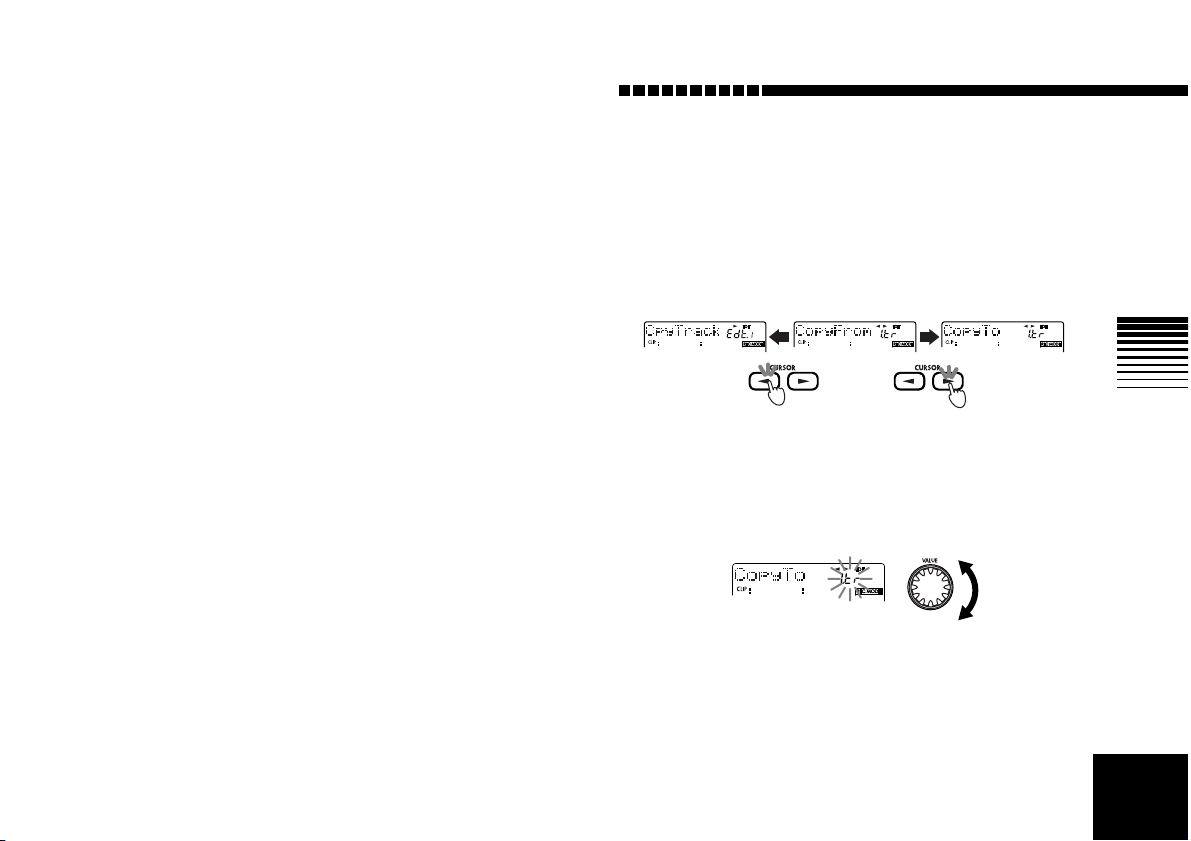
Copy Track — copying a track...............................45
Insert Track “InsTrack”
— inserting a blank space .......................................46
Erase Track “ErsTrack” — erasing a track ...........47
Delete Track “DelTrack” — deleting a track........48
Expansion/Compression — expanding/
compressing a track .................................................48
Copy Virtual Track “CpyV-Trk” — copying to a
virtual track...............................................................50
Delete Virtual Track “DelV-Trk” — deleting a
virtual track...............................................................50
Step 11. Mixdown...........................................51
1. Recording onto a master recorder............................... 51
2. Using the sub input.................................................... 51
3. Creating a stereo MP2 file.......................................... 52
Limitations for a stereo MP2 song ........................ 52
Creating a stereo MP2 file ...................................... 52
Step 12. Saving to your computer ....................52
1. Making USB connections to your computer.............. 53
Windows users......................................................... 53
Macintosh users .......................................................53
2. Saving song files via card........................................... 54
Contents of the card ................................................ 54
3. Card management ...................................................... 55
Recovering a damaged card: Card Recovery ......55
Formatting a card: Format...................................... 55
Mode parameters....................................56
REC MODE Select the recording mode...............56
SYSTEM...........................................................57
P.1 MixerSys: Mixer settings...........................................57
P.2 Foot SW: Foot switch settings....................................57
P.3 UndoSys: Undo settings............................................57
TRK EDIT: Track editing operations....................58
P.1 CpyTrack: Copy a track.............................................. 58
P.2 InsTrack: Insert blank space into a track....................58
P.3 ErsTrack: Erase data from a track.............................. 59
P.4 DelTrack: Delete data from a track.............................59
P.5 ExpTrack: Expand/compress a region of a track........59
P.6 CpyV-Trk: Copy a virtual track................................. 60
P.7 DelV-Trk: Delete a virtual track................................ 60
3
Page 6

V-Track............................................................61
RHYTHM..........................................................61
P.1 Rhythm Pattern..........................................................61
P.2 Tempo..........................................................................61
P.3 Beat.............................................................................61
P.4 RhythmLv: Rhythm volume.......................................61
LOCATE...........................................................62
SONG SEL: Song select.....................................62
P.1 Song Select: select a song............................................62
SONG EDIT......................................................63
P.1 NameSong: edit the song name...................................63
P.2 CopySong: copy a song...............................................63
P.3 DelSong: Delete a song...............................................63
NEW SONG: Creating a new song ...................64
P.1 SongGrade: specify the song grade.............................64
CARD ..............................................................64
P.1 CardInfo (Infomation): View card information..........64
P.2 CdFxSave: Saving an effect user file...........................64
P.3 CdFxLoad: Loading an effect user file.........................65
P.4 CdRecvey: Recover card data......................................65
P.5 CdFormat: Format a card............................................65
USB.................................................................65
Effect parameters.................................... 66
Effect types......................................................66
FX: Effects........................................................67
P.1 FxSelect: select an effect program...............................67
4
P.2 DYNA: dynamics....................................................... 67
P.3 AMP: amplifier...........................................................68
P.4 CABI/EQ: cabinet/equalizer....................................... 68
P.5 MOD: modulation......................................................68
P.6 AMB: ambience.......................................................... 68
P.7 NR/GATE: noise reduction/gate................................ 68
P.8 ProgMVol: program master volume..........................68
P.9 FxRetLv: effect return level setting............................ 68
P.10 FxRetBal: effect return balance setting .................... 69
P.11 Rename: edit the name of the effect........................... 69
FX WRITE/PROG: save an effect.......................69
FX WRITE/KNOB: register an effect to
the Favorites knob...........................................69
PAN: pan........................................................70
PAN: adjust the pan (stereo position)............................... 70
RTM LVL: adjust the rhythm level ..................................70
SEND: adjust the send level .............................................70
RETURN: adjust the return level..................................... 70
Effect modules.........................................71
DYNA .............................................................71
1. LIMITER .............................................................71
2. WAH ................................................................ 71
3. COMP ...............................................................71
AMP................................................................72
1. AMP SIMULATOR/DRIVE ....................................72
2. BASS AMP SIMULATOR ......................................73
3. COMP, ACO .....................................................73
4. SYNTH .............................................................. 74
Page 7

CABI/EQ .........................................................74
1. CABINET ...........................................................74
2. BASS CABINET ..................................................75
3. EQ ....................................................................76
4. MIC SIMULATOR ................................................77
MODULATION .................................................77
1. MODULATION ................................................... 77
AMBIENCE.......................................................79
1. DELAY ...............................................................79
2. AMBIENCE ........................................................79
NR/GATE ........................................................80
1. NR ....................................................................80
2. GATE ................................................................80
Effect Program List ...........................................81
Preset .................................................................................81
User ...................................................................................81
Effect Chain List................................................82
Appendices .............................................84
Troubleshooting...............................................84
No sound ................................................................84
Can’t hear the playback ...........................................84
Can’t hear the input sound .......................................84
[PAN] knobs don’t work ...........................................84
Can’t record ............................................................84
Effect does not apply ................................................85
Rhythm ...................................................................86
Card ....................................................................... 86
USB ........................................................................ 87
Messages........................................................87
Error messages..................................................................88
Rhythm pattern list...........................................91
Specifications ..................................................92
Index ..............................................................94
Block diagram.................................................96
5
Page 8
Introduction
Thank you for purchasing the KORG D4 Digital Recorder .
In order to take full advantage of the D4 and enjoy troublefree operation, please read this manual carefully. After you
have read this manual, please keep it for future reference.
Main features
The D4 is a digital multi-track recorder that uses “CompactFlash” as its recording and storage medium.
The D4 lets you record individual tracks using a guitar,
keyboard, mic, or other instruments, and then mix your
tracks into a completed song — all without requiring any
additional equipment. The D4 also contains a full complement of Editing tools such as copy, delete, expansion,
compression and more.
CompactFlash
CompactFlash provides a convenient and reliable media
format for recording and archiving your data. This solidstate media requires no bulky drive mechanism, keeping
the D4 quiet and portable. You can also use the USB connector to send the recorded data to your computer.
Virtual tracks
The D4 has four recording/playback tracks. Each track
provides 8 virtual tracks. These virtual tracks give you the
×
equivalent of 32 tracks (4 tracks
ing.
8) of multi-track record-
Effects
The built-in effect unit features Korg’s “ ” modeling
technology, and contains 100 different effect programs created by professional musicians and engineers. You can
also save 100 of your own original effect programs in the
user area.
Rhythm patterns
Metronome and PCM rhythm patterns are provided as
reference and to enhance your recordings.
Additional features
The D4 provides other functions such as a tuner and
assignable locate points to meet your recording needs.
6
Page 9
What is ?
(Resonant structure and Electronic circuit Modeling
System) is KORG’s proprietary sound modeling technology
which precisely reproduces the complex character and nature
of both acoustic and electric instruments as well as electronic
circuits in real world environments. emulates a wide
variety of sound generation characteristics including instrument bodies, speakers & cabinets, acoustic fields, microphones, vacuum tubes, transistors, etc.
Introduction
Printing conventions in this manual
[ ]: Keys, and knobs on the panel of the D4 are enclosed in
[square brackets].
“ ”: Parameters that appear in the display are enclosed in
double quotation marks.
1
2
3
Steps
2
3
...
→
p.
■■
, : These symbols indicate cautions or advice.
Display screens in this manual
The parameter values appearing in the display screens
printed in this manual are only examples, and may not be
the same as what appears in the display of your D4.
About your data
The contents of memory may be lost if an unexpected
malfunction occurs, so be sure to make a backup of any
important data. Korg Corporation can take no responsibility for any damages due to loss of data.
...: Steps in a procedure are indicated as
: This indicates a reference page.
1
COPYRIGHT WARNING
This professional device is intended only for use with works
for which you yourself own the copyright, for which you have
received permission from the copyright holder to publicly perform, record, broadcast, sell, and duplicate, or in connection
with activities which constitute “fair use” under copyright
law. If you are not the copyright holder, have not received permission from the copyright holder , or have not engaged in fair
use of the works, you may be violating copyright law, and
may be liable for damages and penalties. If you are unsure
about your rights to a work, please consult a copyright attorney.
KORG TAKES NO RESPONSIBILITY FOR ANY
INFRINGEMENT COMMITTED THROUGH USE OF
KORG PRODUCTS.
7
Page 10
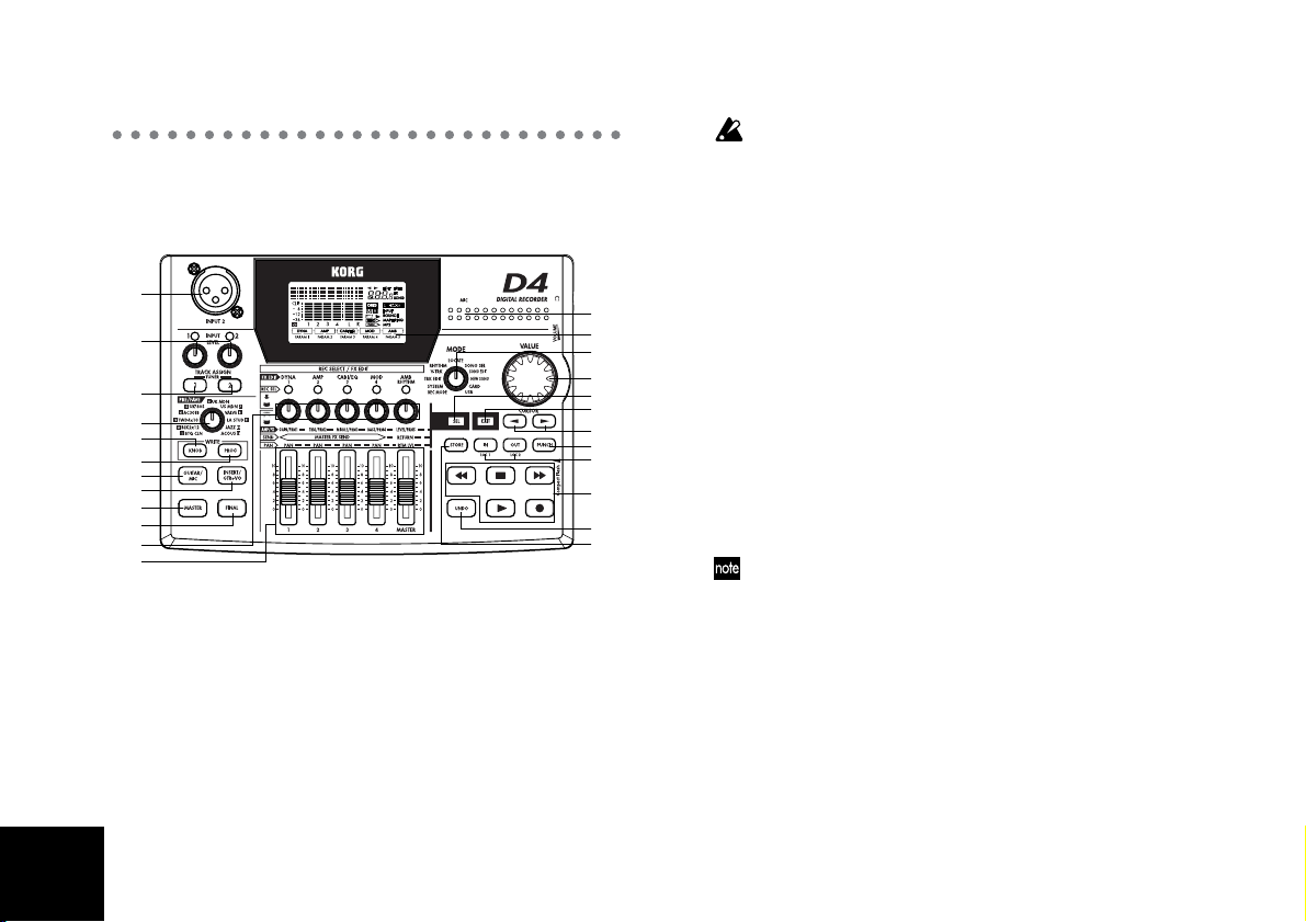
Features of the D4 and their function
1. Top panel
1
3
4
5
6
7
8
9
10
11
13
14
1. [INPUT 2] mic input jack
You can connect a mic to this balanced XLR jack. If
you use this jack, set the rear panel [INPUT 2] switch
to “EXT (MIC).”
2. MIC (internal mic)
3. INPUT LEVEL [1], [2] knobs
These knobs adjust the level of the inputs. The optimal
setting is the highest level that does not cause the
LEDs to light.
12
16
15
22
17
21
20
19
23
24
18
2
You may hear hum or noise if you raise the INPUT LEVEL [1],
[2] knob levels when nothing is connected to the input jacks.
4. TRACK ASSIGN [1], [2] keys
These keys assign are used to assign the signal from
the [INPUT 1] and [INPUT 2] jacks to tracks. The
[INPUT 1] jack corresponds to the TRACK ASSIGN [1]
key, and the [INPUT 2] jack corresponds to the [2] key.
When you press one of the TRACK ASSIGN keys, that
key will light. Next, press the [P AN] knob corresponding to the destination track. Both the REC SELECT
LED and TRACK ASSIGN keys will light, indicating
the input jack is assigned to that track.
TUNER
To access the Tuner mode, press the TRACK ASSIGN
[1], [2] keys simultaneously. The tuner function lets
you tune an external instrument. Since the effects are
bypassed in Tuner mode, this provides a way for you
to compare the sound with the effects on or bypassed.
The Tuner function will not operate during playback or during record-standby.
5. [PRE/FAVE] (favorite) knob
Turn this knob to select the effect you want to use.
You can register your eleven favorite effects to this
knob, and select them simply by turning the knob.
When the D4 is shipped from the factory, the eleven
effects printed on the panel are the effects assigned to
this knob. To assign your own favorites, refer to “Step
7. Using effects” in the Operation section.
8
Page 11
Introduction
6. FX WRITE [KNOB] key
Press this key to register a favorite effect to the [PRE/
FAVE] knob.
7. FX WRITE [PROG] key
After you’ve edited an effect, press this key to save
your custom settings.
8. FX [GUITAR/MIC] key
Press this key to apply an insert effect to the input as
it’s being recorded. If this key is lit, the effect is being
applied. If you press the lit key, the effect will be
bypassed. If you press and hold the key , the ef fect will
turn off.
Only one track can be recorded at a time when you’re using
this effect.
9. FX [INSERT/GTR+VO] key
Press this effect if you want to apply a dual-input
insert effect (to process the sound while it’s being
recorded), for example when using stereo input or
when recording a guitar and vocal duo. If this key is
lit, the effect is being applied. If you press the lit key,
the effect will be bypassed. If you press and hold the
key, the effect will turn off.
10.FX [MASTER] key
Press this key if you want to apply a send/return master
effect during playback or when bouncing or mixing tracks.
If this key is lit, the effect is being applied. If you press the
lit key, the effect will be bypassed. If you press and hold
the key, the effect will turn off.
11.FX [FINAL] key
Press this key if you want to apply a final effect during
playback
is lit, the effect is being applied. If you press the lit key ,
the effect will be bypassed. If you press and hold the
key, the effect will turn off.
or when bouncing or mixing tracks
. If this key
12.Display
This area displays recording and playback level
meters, time information (locate), page information,
and various other parameters.
13.[PAN] knobs (REC SELECT/FX EDIT)
These knobs adjust the panning of each track and the
rhythm level. Depending on the selected mode and the
[SEL] key, you can also press these knobs to switch the
status of each track between playback and recording.
When editing an effect, pressing down on each knob
will select a specific block within the effect chain.
14.Faders
These adjust the volume levels. A fader position of
about “7” on the scale is unity level (recording and playback will be at the same level). At this time, an indication of “-U-” will briefly appear in the value indicator.
1, 2, 3, 4
These faders adjust the volume level of each track. For
tracks not selected for recording by “REC SELECT,”
the faders adjust the playback volume level. For tracks
selected by “REC SELECT,” the faders adjust the
recording level of the input signal.
MASTER
This fader adjusts the volume level of the master L/R
9
Page 12

10
bus. During playback, the sound is output from the
[MASTER OUT] jacks at the volume specified by this
fader. If you’ve selected “BOUNCE,” “MASTERING,”
or “MP2” as the “REC MODE,” this fader adjusts the
overall recording level of the tracks selected by “REC
SELECT.”
15.[VALUE] dial
Use this to select parameters or edit their values.
Pressing down on this dial has the same result as
pressing the CURSOR [ ] key.
16.[MODE] knob
Use this knob to select a specific mode. (→p.24)
17.[EXIT] key
This key returns you to a specific page for each mode
or page. Press it to cancel the selected operation when
editing (i.e., when the “EDIT” indication is lit), or to
return from Effect or Tuner mode to the mode selected
by the [MODE] knob.
18.[STORE] key
Press this key to register a specific point in the song
(time location) to the [IN (LOC1)] or [OUT (LOC2)]
(locate point) keys. When renaming a song, press this
key to assign the name and store the song. For details
on how to register a time location, refer to “3. Using
locate points to change the time” in “Step 5. Viewing
and changing the time” of the Operation section.
19.[IN (LOC1)], [OUT (LOC2)] (locate point) keys
Pressing these keys moves the song to their stored time
location. After pressing the [STORE] key, press one of
these keys to store the current time location to that key.
In the auto-punch record mode (the [PUNCH] key will
be lit), recording will automatically begin and end
(punch-in/out) at the times specified by these keys.
The times registered to these keys are also used for
track editing (“TRK EDIT” mode) and for auto-punch
recording (See “Step 3. Re-recording a specified time
region of a track: Auto punch-in/out.”) For details on
how to register a time location, refer to “3. Using
locate points to change the time” in “Step 5. Viewing
and changing the time” of the Operation section.
20.[PUNCH] key
This key turns auto-punch recording on/off.
On (key lit): Auto-punch recording .
Off (key unlit): Conventional recording.
For details on using auto-punch recording, refer to
“Re-recording a specified time region of a track: Auto
punch-in/out” in “Step 3. Recording” of the Operation section.
21.CURSOR [ ], [ ] keys
Use these keys to move between pages in the display.
The key(s) will light to indicate the direction(s) in
which it is possible to move.
22.[SEL] key
Use this key to select the function of the [PAN] knobs.
The display shows the currently selected function.
23.TRANSPORT keys
Use these keys to operate the recorder (e.g., play, record).
PLAY
This plays the currently selected song.
Page 13
Introduction
1234
5
6
789
If you’ve used the [REC SEL] keys to select a recording
track, press the [REC] key and then press the [PLAY]
key to begin recording.
The [PLAY] key will remain lit during playback or
recording.
If you press this key during playback, the playback
will slow down to half-speed - without changing the
pitch - making it easy to play along with a difficult
phrase as you practice.
While setting the In, Out, To, or End times in track
editing, you can press this key to play back approximately two seconds from that time location.
REC
Pressing this key will arm the D4 for recording (recordready mode). The key will blink. In order to enter
record-ready mode, you need to press the [PAN]
knob(s) for the track(s) you wish to record - the selected
track’s LED will light. When you then press the [PLAY]
key, the key will light and recording will begin.
STOP
This key stops the recording or playback; the recorder
will stop.
If you press this key while already stopped, the song
will be saved and you will return to the beginning of
that song.
REW (Rewind)
This key moves to the beginning of the song. If you
press and hold this key during playback, the time
location will move rapidly toward the beginning of
the song.
FF (Fast Forward)
If you press and hold this key during playback, the
time location will move rapidly toward the end of the
song.
24.[UNDO] key
Use this key to undo the most recent recording or
track editing operation, or to cancel the Undo operation (i.e., “redo”)
After performing a recording or editing operation,
you can press the [UNDO] key to return to the state
prior to executing that operation.
In order to use this function, the “SYSTEM” mode “UNDO”
page setting “AutoUndo” must be turned “On.”
Undo information is preserved until you perform the next
recording or track editing operation.
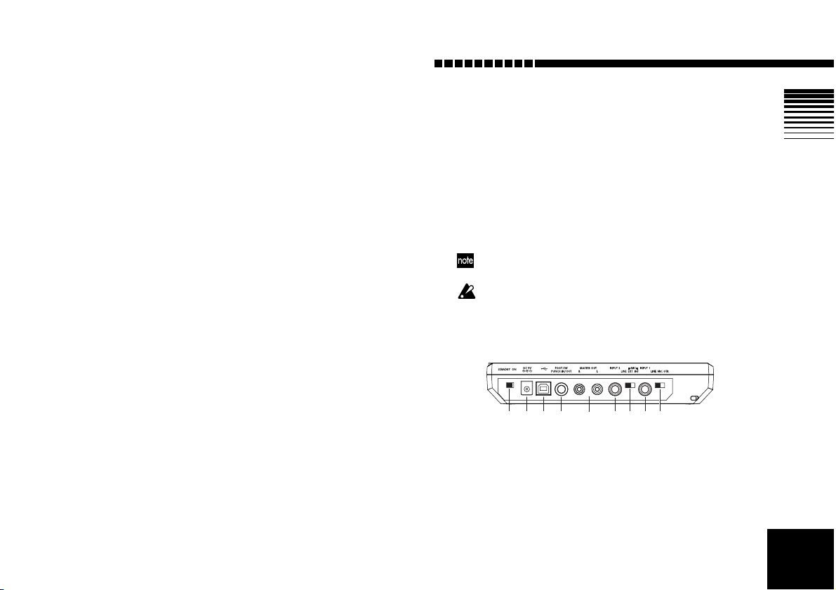
2. Rear panel
1. [INPUT 1] switch
Set this switch for the type of device connected to the
[INPUT 1] jack.
GTR: Use this setting if you’ve connected a guitar or
bass guitar.
MIC: Use this setting if you’ve connected a mic.
LINE: Use this setting if you’ve connected a line-level
11
Page 14
12
132
device (e.g., the output of a keyboard or effect processor).
2. [INPUT 1] jack
You can connect a guitar, bass, or keyboard to this
monaural phone jack.
3. [INPUT 2] switch
Set this switch for the type of device connected to the
[INPUT 2] jack.
(MIC) INT: Use this setting if you’re using the D4’s
internal mic.
(MIC) EXT: Use this setting if you’re using the
[INPUT 2] jack at mic level. This is appropriate for a
mic input.
LINE: Use this setting if you’re using the [INPUT 2]
jack at line level. This is appropriate for a line-level
device. In this case, you can’t use the top panel
[INPUT 2] mic input jack.
4. [INPUT 2] jack
You can connect a line-level device (e.g., the output of
a keyboard or effect processor) here. You can also use
this with the [INPUT 1] jack for stereo input. This is a
monaural phone jack.
When you use this jack, you can’t use the top panel
[INPUT 2] mic input jack.
5. [MASTER OUT] jack
These jacks output the stereo audio signal. Connect
the D4 to your external monitor system or recording
equipment via these RCA-style jacks.
6. [PUNCH IN/OUT] jack
You can connect a pedal switch (sold separately: PS-1)
to this jack for perform punch-in/out recording.
7. [USB] connector
Use a USB cable to connect the D4 to your computer.
(→p.53)
8. [DC 9V] connector
Connect the included AC adapter to this connector.
9. [POWER] switch
This switches the D4 between On and standby.
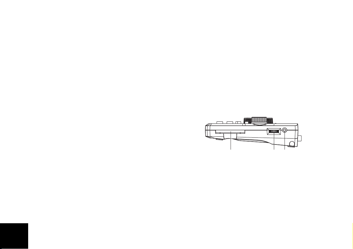
3. Side panels
1. CARD slot
Insert CompactFlash media into this slot.
2. [PHONE] jack
Connect a pair of stereo headphones to this 1/8" miniphone jack.
3. [PHONE LEVEL] knob
This knob adjusts the volume level of the headphones.
Page 15
Introduction
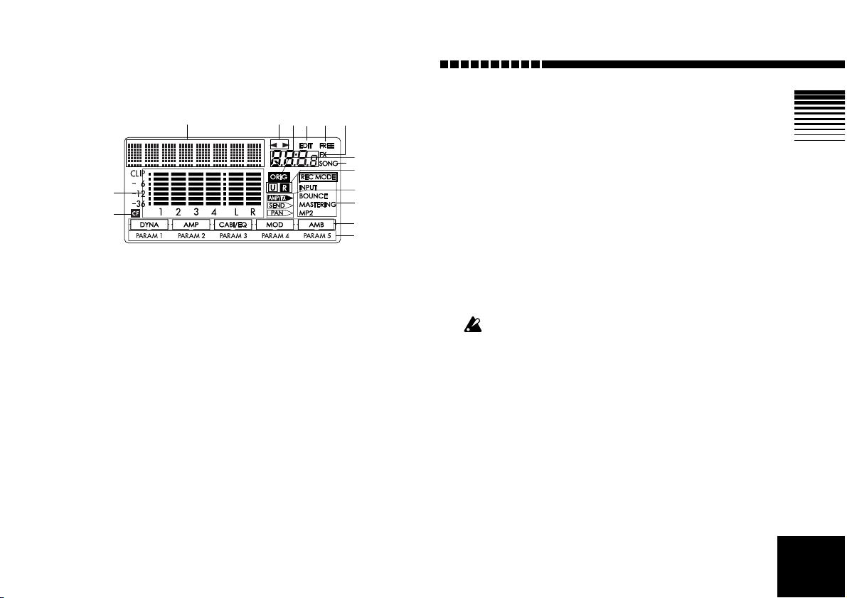
4. Display screen
1
8
9
1. Page parameter display/Location counter display
This area displays the current time location and
parameter information.
2. Page guide display
This area shows in which direction you can move
(using the [CURSOR] keys) to access additional pages.
3. Value display
This area shows the value of the parameter being
edited, or information regarding the page or program.
4. EDIT icon
This icon will be shown when it is possible to use the
[VALUE] dial to edit the value of the selected parameter.
5. Free icon
This icon is shown when the value display is indicating the remaining space on the card.
23 5 64
6. Fx icon
This icon is shown when the value display is indicating the number of the currently selected effect and its
effect chain.
10
7
11
12
13
14
15
7. Song icon
This icon is shown when the value display is indicating the number of the currently selected song and the
grade (recording quality) of that song.
8. Level meter
This area indicates the input/recording and output/
playback level of each track.
9. Card access icon
This icon is shown when data is being written to or
read from the CompactFlash card.
Never turn off the power when the card access icon is displayed. Doing so may destroy not only the currently selected
song, but also the data in the card as well as the card itself.
10.Original value icon
When the current value of the parameter being edited
is the same as its stored value, the “ORIG” icon will
appear.
11.Undo/Redo icons
These icons will appear when the undo/redo functions are available.
12.[PAN] knob icon
These icons indicate the current function of the [PAN]
knobs.
13
Page 16

13.Record mode icon
These icons indicate the current recording mode. Set
the [MODE] knob to “REC MODE” and use the
[VALUE] dial to select the appropriate recording
mode.
INPUT: The input signal will be recorded. This is the
normal recording mode.
BOUNCE: In the BOUNCE recording mode, up to
three tracks of playback and one external input can be
bounced (mixed) down to one track; or you can chose
to have two tracks of playback and two external
inputs to be bounced down to two tracks.
MASTERING: In the MASTERING recording mode,
all four tracks of playback can be mixed down onto
one or two of the tracks.
MP2: In this mode, four tracks of playback will be converted to a two-track MP2 stereo file (without overwriting the existing four tracks).
14.Effect chain
This icons in this area indicate the on/off status of
each of the modules in an effect chain.
15.Effect parameters
These icons will appear to indicate that editable
parameters exist for the selected effects. Use the [PAN]
knobs to edit these parameters. The indicator for the
parameter currently being edited will blink.
14
Page 17
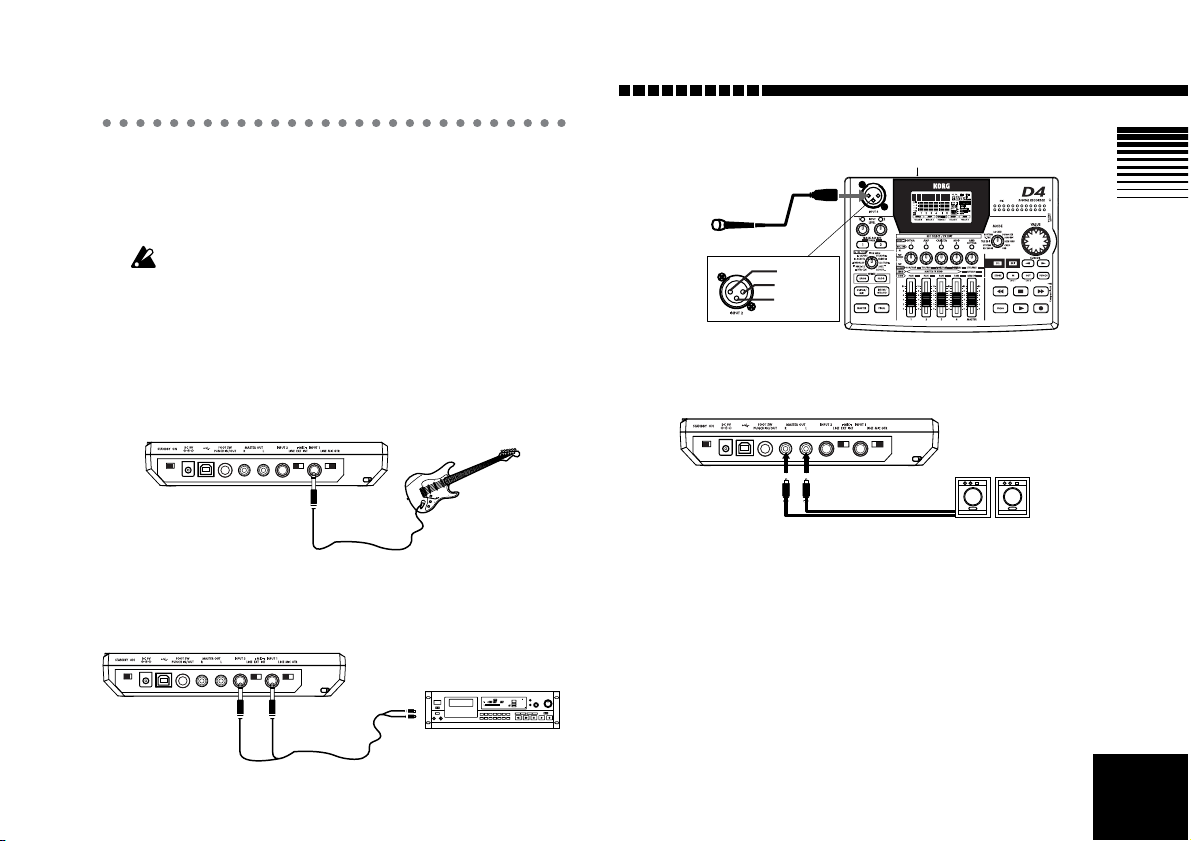
Connections
[MASTER OUT]
Powered monitor
speakers, etc.
The diagram below shows basic connections for the D4.
Adapt these instructions as appropriate for your equipment, and make the necessary connections.
The power must be turned off while you make connections.
1. Input
Set the [INPUT 1] and [INPUT 2] switches appropriately
for the input device you’ve connected. (→p.11)
Connecting a guitar
[INPUT 1] GTR
Connecting a line-level device
[INPUT 1] LINE
[INPUT 2] LINE
Connecting a mic (to the XLR jack)
Mic
2:HOT
1:GND
3:COLD
2. Output
Introduction
[INPUT 2] (MIC) EXT
OUTPUT L/R
CD player, cassette deck, etc.
15
Page 18
Inserting or removing a card
In order to record on the D4, you will need a CompactFlash card (which we’ll refer to simply as a “card” in this
manual).
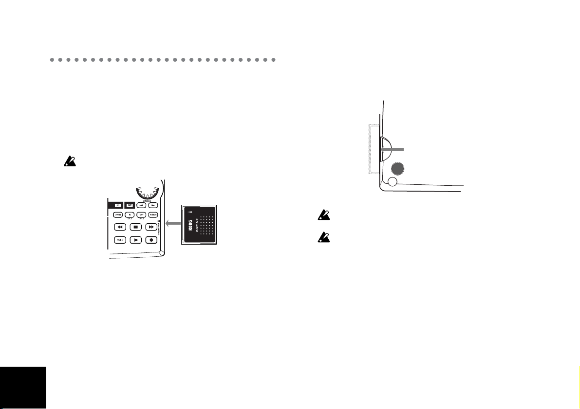
1. Inserting a card
Insert the card with the label facing upward. Firmly
push the card all the way into the card slot.
Be careful to insert the card in the correct direction.
2. Removing a card
Grasp the ridge located on the underside of the card,
and pull it out toward yourself.
Never insert or remove the card while the power is on.
Doing so may damage the card.
The card may be damaged if you use excessive force when
inserting or removing it.
Cards that can be used with the D4
The D4 can use CompactFlash cards of capacities ranging
from 16 MB to 2 GB. Never attempt to use any other type
of CompactFlash card, since this may cause the D4 to stop
working.
Card handling
Do not bend the card, or subject it to strong physical shock
or high temperatures.
16
Page 19
Switching the power on/standby
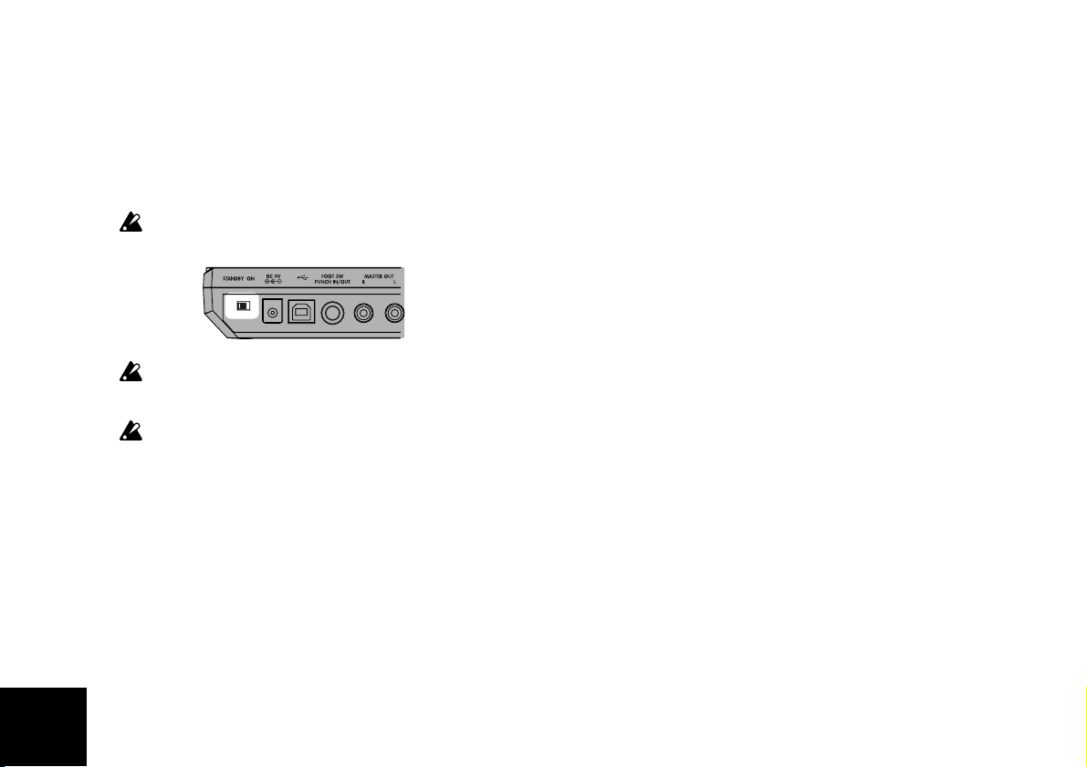
1. Preparing to turn on the power
Before you connect the power supply, make sure that the
[POWER] switch is set to the STANDBY position.
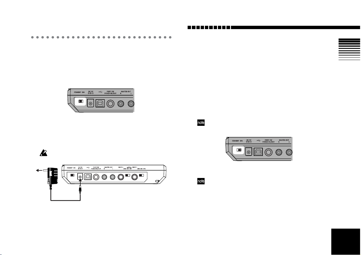
Connecting the AC adapter
Plug the connector of the included AC adapter firmly into
the [DC 9V] input connector. Then connect the AC adapter
to an AC power outlet.
Never use any AC adapter other than the included one.
AC
Introduction
2. Turning the power on
Here’s the correct way to turn on the power of the D4 and
any other connected devices.
1 Lower the [MASTER] fader to 0.
Also lower the volume of any connected external
devices to the minimum setting.
2 Turn on the power of any connected external
devices.
Turn on the power of external input devices such as a
keyboard that will be sending audio to the D4.
3 Turn on the power of the D4.
Turn the [POWER] switch on.
The song that had been selected when the power was last
turned off will be selected.
The start-up screen will appear in the display.
If the start-up screen does not appear when you turn on the
power, check the following points.
• AC adapter is connected, and CompactFlash card is
inserted in the correct direction
4 Turn the on the power of any external output devices
such as your audio monitor system.
17
Page 20
3. Switching the power off
Make sure that operations such as song playback or
recording are completed, and turn off the power by
reversing the “Turning the power on” procedure from the
previous page.
Before you power-off, you must press the [ST OP] key to save
the song to the card.
Turn the volume of all connected devices to the minimum
setting, and turn off each power switch in order, beginning
with the last device that receives the audio signal.
Never turn off the power when the card access icon is displayed. Doing so will destroy not only the selected song, but
may also destroy the songs on the card as well as the CompactFlash itself.
18
Page 21
Listening to the demo songs
The included card contains demo songs. Here’s how you
can listen to these demo songs.
1 Connect headphones or a monitor amp to the D4.
(→p.15)
2 Turn on the power of the D4. (→p.17)
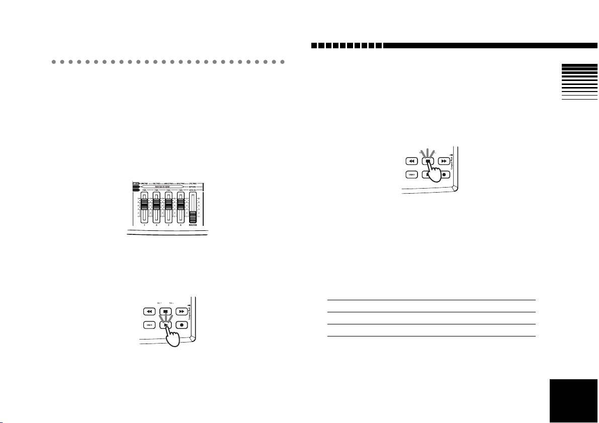
3 Set the [TRACK] fader of the D4 to 7, and the [MAS-
TER] fader to 0.
4 Select the song that you want to play back.
(→p.28: Step 2 “2. Selecting a different song”)
5 Press the [PLAY] key to begin playback.
Introduction
6 Slowly raise the [MASTER] fader to adjust the vol-
ume level.
If you are using headphones, raise the [MASTER]
fader to about 6, and then use the [PHONE LEVEL]
knob to make adjustments.
7 When the demo song has finished playing, press the
[STOP] key to stop playback.
Demo song list
“BOA BLUES”
Written and performed by Rob Math
© 2004 KORGinc. -all rights reserved.“Duck Teeth”
Setting
Tr1 Tr2 Tr3 Tr4
PANL5R25 Center Center
FADER 85 85 85 85
FINAL EFFECT P63: Room_RV
19
Page 22
Quick start
If you just can’t wait to get started, this section will explain
how to connect your guitar, recor d your playing on one track,
and then play it back.
1. Preparations
Insert the card
Insert the card (CompactFlash) into the card slot.
(→p.16)
The CompactFlash card that came with your D4 is
already formatted and contains the demo songs. However, if you are using a new CompactFlash card, you
will need to format it before you begin recording.
(→p.55)
If you format the CompactFlash card that was included
with the D4, you will lose all the demo data (demo song
and effect data) that it contained.
Connect your guitar
Connect a shielded cable (mono phone plug) to your
guitar. Connect the other end of the cable to the D4’s
[INPUT1] jack.
Set the D4’s [INPUT1] switch to GTR.
Connect your headphones
Connect your headphones to the D4’s [PHONE] jack.
Set the [PHONE LEVEL] knob to 0.
If you want to connect an amp or audio system, refer to
p.15.
2. Turn the power on
Connect the AC adapter
Connect the included AC adapter to the [DC 9V] jack.
Set the [MASTER] fader to “0”
Lower the D4’s [MASTER] fader.
Turn the power on
Turn on the [POWER] switch located on the rear panel
of the D4, and the start-up screen will appear in the
display.
20
Page 23

Quick start
3. Create a new song
Set the [MODE] knob to “NEW SONG”
If no songs have been recorded on the card, then
“MakeNew!” will appear automatically.
Specify the song grade
The display indicates “SngGrade.”
Use the [VALUE] dial to select the grade (recording
quality) of the new song you’re going to create.
Create the song
Press the CURSOR [ ] key. An empty song named
“NEW SONG” has now been created.
Press the [EXIT] key
The D4 will be in Play mode.
4. Assign the input
Press the TRACK ASSIGN [1] key
The key will light.
Select the recording track
By default, track 1 is automatically selected as the
recording track; the TRACK ASSIGN [1] key and REC
SELECT [1] LED will light. If you want to select a track
other than track 1 as the recording track, press the
[PAN] knob corresponding to that track to select it.
Set the input level
Adjust INPUT LEVEL [1] as you watch the LED. Set
the level as high as possible without letting the LED
light red.
Set the monitoring level
Gradually raise the [TRACK 1] fader as you watch the
level meter [1], and make sure that you are hearing
sound. Use the [MASTER] fader and [PHONE] knob
to adjust the monitor volume.
21
Page 24
5. Select an effect
6. Record
22
Press the [GUITAR/MIC] key
The guitar/mic effects will appear.
Use the [VALUE] dial to select an
effect program
Play your guitar to hear the sound.
Edit an effect module
Press the [PAN] knob for one of the effect modules
within the selected effect chain, and then turn the
[VALUE] dial to select that effect module. You can
turn the [PAN] knobs to edit the value of the parameters in that module.
Press the [EXIT] key
You will return to Play mode.
Adjust the recording level
Use the [TRACK 1] fader to adjust the recording level.
While you watch level meter [1], gradually raise the
fader as far as possible without allowing the level to
reach CLIP. Use the [MASTER] fader and [PHONE]
knob to adjust the monitor volume.
Arm the D4 for recording
Press the [REC] key to put the D4 into record-ready
mode. The [REC] key will blink.
Record!
When you are ready to perform, press the [PLAY] key.
Recording will start, and you may begin playing your
instrument. During recording, the [REC] key and
[PLAY] key will be lit.
Stop recording
When you’re finished performing, press the [STOP]
key. Recording will stop, and the [REC] key and
[PLAY] key will go dark.
Page 25
7. Playback
Press the [REW] key
The time location will return to the beginning of the
song.
Disarm the recording track
If the [REC SELECT] LED of the track you specified as
the recording track in “4. Record” is still lit, press the
[PAN] knob corresponding to that track again, and
the LED will go dark.
Listen to the recording
Press the [PLAY] key. Playback will begin. During
playback, the [PLAY] key will be lit.
Use the [MASTER] fader to adjust the volume.
Stop the playback
To stop playback, press the [STOP] key. Playback will
stop, and the [PLAY] key will go dark. To listen again,
repeat steps 1–4.
Quick start
23
Page 26
Operation
Step 1. Basic operation
This section explains basic operation of the D4.
1. Selecting modes
The functions of the D4 are organized into eleven modes
selected by the [MODE] knob; and four sub-modes (Effect,
Effect Write, Tuner, and Punch-Rec) accessed by pressing
to various keys.
You can access one of the sub-modes from any mode simply by pressing the corresponding key. If a sub-mode is
selected, you can press the [EXIT] key to return to the
mode currently selected by the [MODE] knob.
Play mode
This is the default mode that the D4 will enter when you
first turn the power on. Here you can play back and
record a song. The display shows a counter.
Modes selected by the [MODE] knob
Turn the [MODE] knob to select a mode. If you turn the
[MODE] knob while a sub-mode is selected, The D4 will
enter the newly selected mode after you exit the submode.
REC MODE (Record Mode)
This mode is used to specify the recording mode (e.g.,
bounce or stereo MP2 conversion).
SYSTEM
This mode is used to make basic settings for the recorder.
TRK EDIT (Track Edit)
24
This mode is used to perform track editing operations
such as Copy or Erase.
V-TRK (Virtual Track)
This mode is used to select virtual tracks.
RHYTHM
This mode is used to specify the tempo and to select
rhythm and metronome patterns.
LOCATE
In this mode, you can move to a different time location within
the song.
SONG SEL (Song Select)
Use this mode when you want to select a different song.
SONG EDIT
This mode is used to perform song editing operations
such as Name, Copy, and Delete.
NEW SONG
Use this mode when you want to create a new song.
CARD
This mode is used to perform card-related operations.
USB
This mode is used to exchange data with your computer
via USB.
Sub-modes
Effect
Press the FX [GUITAR/MIC], [INSERT/GTR+VO], [MASTER], or [FINAL] key to enter the Effect sub-mode in
order to select or edit effects. The key that you selected
will be lit, and this will determine the location at which
the effect is inserted and the effect types that are available.
Write
Press the FX WRITE [KNOB] key or the [PROG] key to
access the Write sub-mode. The [KNOB] key lets you register the selected effect to the Favorites knob. The [PROG] key
lets you rename an effect and write it into the D4’s internal
memory.
Page 27
Operation
Tuner
Press the TRACK ASSIGN [1] key and [2] key simultaneously to access the Tuner sub-mode. Next, use the
TRACK ASSIGN [1] key or [2] key to select the input
([INPUT 1] or [INPUT 2]) signal that you want to send to
the tuner.
Punch Rec
Press the [PUNCH] key to select the Punch Rec sub-mode
if you want to use auto-punch recording. Auto-punch
recording will occur from the time location specified by
the [IN (LOC1)] key to the time location specified by the
[OUT (LOC2)] key.
2. Selecting and editing parameters
Selecting a parameter
After you’ve selected a mode using the [MODE] knob, use
the [CURSOR] keys to move to the page containing the
parameter that you wish to edit.
The page guide indication shows whether more pages
exist in each direction. T o move to another page, press the
[CURSOR] key for that direction.
Editing a parameter
If the displayed page contains a parameter whose value
you can edit, the value display will blink and the edit icon
will appear. Turn the [VALUE] dial to edit the parameter.
25
Page 28
26
Using the [PAN] knobs to select/edit parameters
The [PAN] knobs can be used to edit the value of certain
parameters.
Use the [SEL] key to switch the function of the [PAN]
knobs. An icon in the display indicates the parameter that
can currently be edited.
AMP/FX: If you press the FX [GUITAR+MIC], [INSERT/
GTR+VO], [MASTER], or [FINAL] key, the [PAN] knobs
will edit effect parameters 1–5.
SEND: If you press the [SEL] key to select SEND (and the
[MASTER] key is lit), the [PAN] knobs will control the
master sends and return.
If you use the [PAN] knobs to edit parameters in this way,
the physical position of the [PAN] knobs will no longer
match the actual panning of each track.
Canceling an edit (Undo/Redo)
After performing a track editing operation, you can use
the Undo function to return to the condition prior to executing the edit. If the undo icon “ ” is shown, you can
press the [UNDO] key to execute the Undo function. After
undoing, the Redo icon “ ” will light, and you can use
the same operation to Redo the edit, returning to the condition prior to executing Undo.
The Undo/Redo function also provides a convenient way
to compare the original version to the edited version,
allowing you to be sure the edit delivered the result that
you wanted.
In order to use this function, the System mode “UndoSys”
page setting “AutoUndo” must be turned “On.” (→p.57)
Undo is maintained until the next time you record or perform a track editing operation.
3. Tuning
The D4 has a built-in tuner function. This lets you tune an
instrument that is connected to the [INPUT 1] or [INPUT
2] jack, or tune an instrument using the internal mic.
Tuning your guitar
1 Connect your guitar to the [INPUT 1] jack.
Set the [INPUT 1] switch to GTR.
2 Enter Tuner mode.
Press the TRACK ASSIGN [1] key and [2] key simultaneously.
3 Verify the input.
The [INPUT 1] LED will blink.
If the input level is too low, adjust the INPUT LEVEL [1]
knob.
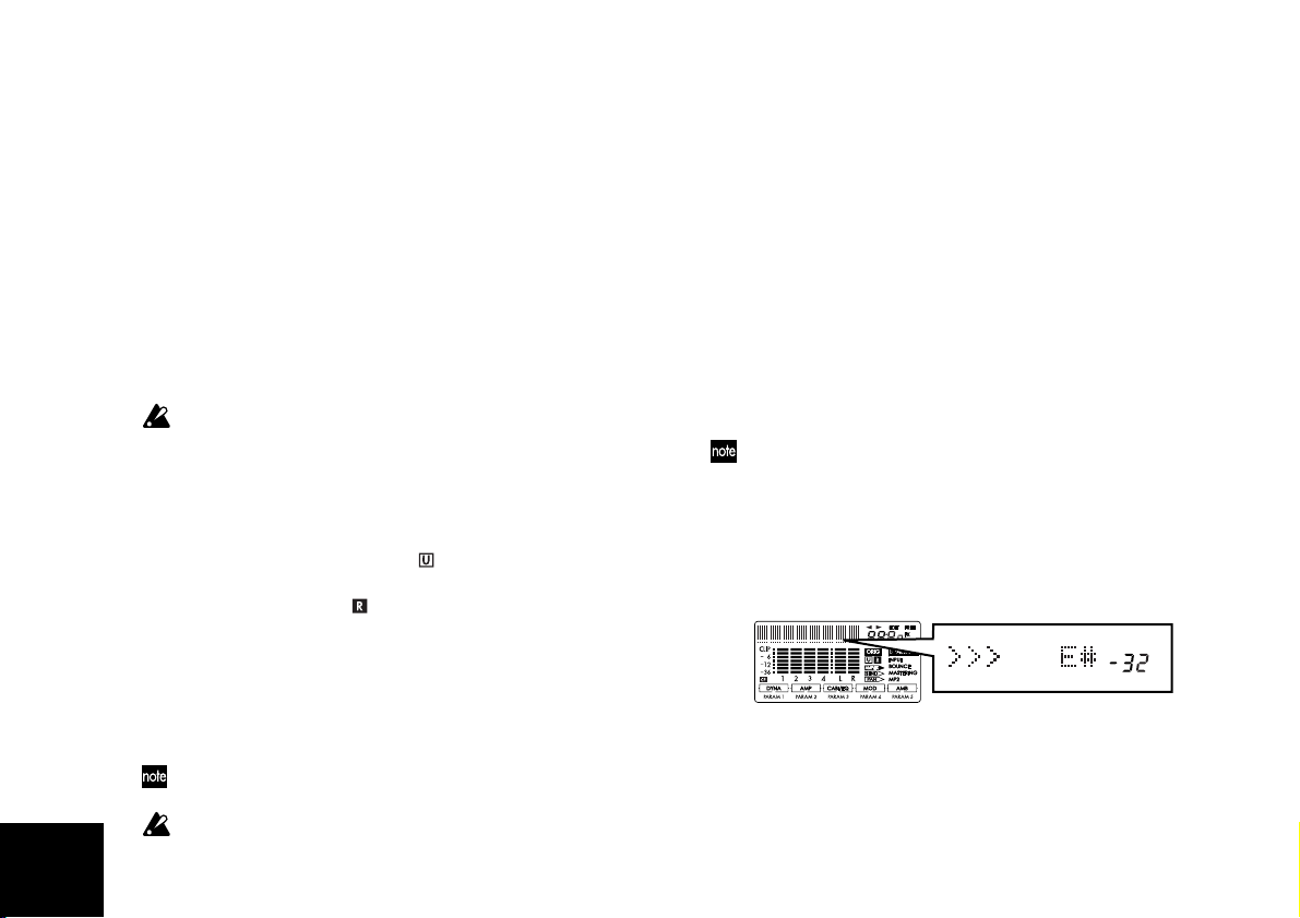
4 Tune your instrument.
Make sure that your guitar is connected to the
[INPUT 1] jack, and play a string on your guitar. The
character display area of the screen will function as a
tuning meter, and will display the note name.
Tune the string while watching the amount of tuning
difference (displayed in units of cents) and the meter
in the display.
The reference pitch frequency is A=440 Hz.
Page 29
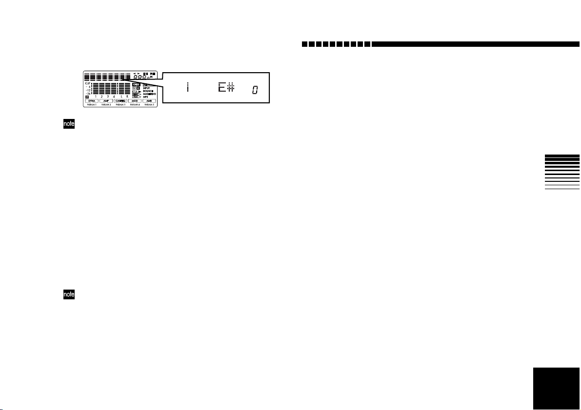
When the tuning is correct
If you do not want the sound to be heard while tuning, set
the [MASTER] fader to 0.
5 Exit Tuner mode.
Press the [EXIT] key to exit Tuner mode.
Tuning your acoustic guitar
Here’s how you can use the D4’s internal mic to tune your
acoustic guitar.
1 Select the internal mic.
Set the [INPUT 2] switch to (MIC) INT.
2 Enter Tuner mode.
Press the TRACK ASSIGN [1] key and [2] key simultaneously.
3 Select the input.
Press the TRACK ASSIGN [2] key. The [INPUT 2] jack
will be selected, and its LED will blink.
If the input level is too low, adjust the INPUT LEVEL [2]
knob.
4 Tune your instrument.
5 Exit Tuner mode.
Press the [EXIT] key to exit Tuner mode.
Operation
27
Page 30

Step 2. Creating/selecting a song
1. Creating a new song
Before you can begin recording, you must create a new
blank song.
1 Set the [MODE] knob to “NEW SONG.”
2 Select the song grade.
The display will indicate “SngGrade.”
Use the [VALUE] dial to select the song grade (recording quality) that’s appropriate for the desired recording quality and/or time.
Eco(Economy) Extended-length recording. Select this
when you want to record for an extended
time.
Std(Standard) Standard. Normally you will select this
grade.
Hiq(High Quality) High audio quality. Select this when you
want to record at a high audio quality. The
available recording time will be shorter.
The song grade that you select here cannot be changed after
the song is created.
3 Create the song.
After you’ve used the [VALUE] dial to select the song
grade, press the CURSOR [ ] key. A song named
“NEW SONG” will be created following the highest
existing song number.
If you decide not to create a new song, press the [EXIT] key.
2. Selecting a different song
To select the previous-numbered song
Hold down the [STOP] key and press the [REW] key
to move to the beginning of the next lower-numbered
song.
To select the next-numbered song
Hold down the [STOP] key and press the [FF] key to
move to the beginning of the next higher-numbered
song.
To select a song directly by name or number
1 Set the [MODE] knob to “SONG SEL”.
The name and number of the currently selected song
is displayed.
2 Use the [VALUE] dial to display the desired song
name and number.
3 Press the CURSOR [ ] key to select the song.
When you switch songs, each track will be at the volume
level at which the faders were when you switched songs.
Depending on the state of the faders, the playback volume
might be excessive, so please use caution.
28
Page 31

3. Changing the name of a song
[INPUT 1][INPUT 2]
[OUTPUT L/R]
LINE
LINE
The default name for any newly created song will be
“NEW SONG.” So that you will be able to tell your songs
apart, we recommend that you change the song name. A
song name of up to 16 characters can be assigned.
Characters available for a song name
(Space), A…Z, a…z, 0…9, @, +, -,
!, #, $, %, ', (, ), {, }, _, “
To change the name of a song
1 Select the song whose name you want to change.
→“2. Selecting a different song”
2 Set the [MODE] knob to “SONG EDIT”.
3 Use the [VALUE] dial to select “NameSong.”
4 Press the CURSOR [ ] key to access the song
renaming page.
The character you’re editing will blink.
5 Use the [VALUE] dial to edit the song name.
The character will change as you turn the [VALUE]
dial. To move to a different character to change, press
the CURSOR [ ]/[ ] keys.
6 When you are finished entering the name, press the
[STORE] key.
The display will ask “NameOK?,” Use the [VALUE]
dial to select “Yes,” and then press the CURSOR [ ]
key. If you select “No,” the previous name will reappear.
Operation
Step 3. Recording
1. Recording methods
This section explains the different recording methods
available on the D4.
For basic recording, refer to “Quick Start.”
Recording on two tracks
Here’s how to record on two tracks simultaneously.
1 Connect the input device.
Lower the D4’s [MASTER] fader, set the [INPUT 1]
and [INPUT 2] switches both to LINE, and connect
your keyboard etc. to the [INPUT 1] and [INPUT 2]
jacks.
2 Specify the two tracks on which you want to record.
Press the TRACK ASSIGN [1] key; the key will light.
Press one of the [PAN] knobs to select a track for
recording. Using the same procedure, press the TRACK
ASSIGN [2] key and select another recording track.
29
Page 32

30
If you press and hold a TRACK ASSIGN key, the REC
SELECT LED of the currently selected track will light.
You can also listen to rhythm while you record. (→p.43)
If you’re in Effect mode, press the [EXIT] key to return to Play
mode before specifying the recording track. If the [GUITAR/
MIC] key is lit, you can record on only one track at a time.
3 Check the input level.
While watching the INPUT LEVEL LED, produce
sound on your keyboard (or other input device) and
adjust the INPUT LEVEL [1] knob. Adjust the level as
high as possible without allowing the LED to light.
Adjust the INPUT LEVEL [2] knob in the same way.
You can also apply an effect to the input source. (→p.37)
To listen to the sound that is being input, raise the [TRACK]
faders and the [MASTER] fader to about 6.
4 Set the recording level.
Use the [TRACK] faders to adjust the recording level.
Watch the level meter, and slowly move the fader up
as high as possible without allowing the signal to
reach CLIP. Use the [MASTER] fader and [PHONE
LEVEL] knob to adjust the monitor volume.
5 Set the current time to the location from which you
want to begin recording.
If you want to begin recording at a different time location, use the [MODE] knob to select “LOCATE” mode.
6 Verify the tracks that are set to record.
Make sure that the REC SELECT LEDs are lit for the
tracks you want to record. If they are not lit, return to
step 2.
7 Press the [REC] key to enter record-ready mode.
The [REC] key will blink.
The value display indicates the amount of time available for recording.
8 Begin recording.
When you’re ready, press the [PLAY] key. The D4 will
start recording, and you can begin performing on your
instrument. During recording, the [REC] key and
[PLAY] key will be lit.
9 Stop recording.
When you’re finished performing, press the [STOP]
key. Recording will stop, and the [REC] key and
[PLAY] key will go dark.
2. Additional recording
Using virtual tracks to record
The D4 is a four-track recorder , but each track has 8 virtual
tracks (A–H). You can record on any of the virtual tracks.
1 Select the virtual track on which you will record.
Use the [MODE] knob to select “V-TRK” mode. Use
the CURSOR [ ]/[ ] keys to select a track number,
and use the [VALUE] dial to select a virtual track.
2 Adjust the recording level of your input device, and
record.
Refer to “1. Recording methods” steps 1–4.
Overdubbing — listening to the playback while you record another track
The technique of listening to the playback of previouslyrecorded tracks while you record another track is called
“overdubbing.” For example, this can be used when you
Page 33

Operation
want to listen to previously-recorded backing tracks while
you record a lead guitar performance.
1 Select the track that you want to record.
When you press the TRACK ASSIGN [1] or [2] key, the
key you pressed will light. Press one of the [PAN] knobs
to select the recording track. Raise the [TRACK] faders
of the tracks you want to hear play back as you record.
2 Adjust the recording level of the input source, and
press the [PLAY] key.
You can practice your performance while listening to the
previously-recorded tracks, just as if you were actually
recording. Adjust the level of your input source (instrument), and practice playing and working out your musical ideas until you are ready to actually record.
If you can’t hear the input source, go to “SYSTEM” mode
and in “MixerSys,” press the CURSOR [ ] key to turn
“AutoIn” Off. (→p.57)
3 Start recording.
Press the [REC] key. When you’re ready, press the
[PLAY] key to begin recording. Press the [STOP] key
when you are done.
If you need to move to a different time location, use the
“LOCATE” mode.
Punch-in/out — re-recording a portion of a track
If you make a mistake in one part of your recorded performance, or if you are not happy with a certain part of your
performance, you can re-record just a specific portion of
the track without having to re-record the entire track from
the beginning, or without having to play through to the
end of the track.
“Punch-in” is the action of switching the song from playback
mode to record mode, and “punch-out” is the action of
switching from record mode back to playback mode.
1 Adjust the recording level of the input source.
Refer to “1. Recording methods” steps 1–4.
2 Set the “AutoIn” parameter to “On.”
Use the [MODE] knob to select “SYSTEM” mode, and
use the [VALUE] dial to select “MixerSys.” Press the
CURSOR [ ] key and use the [VALUE] dial to turn
the “AutoIn” parameter “On.” This will set the “automatic input switching” monitor feature on.
When “AutoIn” is “Off,” you will always hear the input
sound of the track being recorded. If this is turned “On,” the
sound recorded on that track will play back during playback,
and during recording this will automatically switch to the
sound of the assigned input source. (→p.57)
Turn the [MODE] knob to return to “LOCATE” mode.
3 Set the time to a location slightly earlier than the
point where you want to begin recording. (→p.35)
4 Connect a pedal switch (PS-1, sold separately) to the
[PUNCH IN/OUT] jack.
If you don’t have a pedal switch, you can punch-in/out
manually; proceed to step 5.
5 Press the [PLAY] key to begin play back.
You will be listening to the playback of the previously
recorded tracks, including the playback of the track
that you will be punch-recording.
6 Press the pedal switch at the point where you want
to start recording.
Recording will start (manual punch-in). Now you will
31
Page 34

32
be listening to the sound of the external input source.
If you don’t have a pedal switch, press the [REC] key at the
point where you want to start recording.
7 Press the pedal switch at the point where you want
to stop recording.
Recording will end, and the track will switch back to
playback (manual punch-out). Now you will be listening to the playback of the track.
If you don’t have a pedal switch, press the [REC] key at the
point where you want to stop recording.
8 Press the [STOP] key to stop playback.
Now you can listen to the playback of the entire track.
If you are not satisfied with the results, you can press
the [UNDO] key and try again.
Auto Punch-In/Out — Re-recording a pre-specified
region of the track
There is also a way to automatically punch-in and punchout without having to manually press a key or step on a
pedal switch at the desired moment. This is convenient iff
you’re recording a performance (such as guitar) that
requires both hands.
1 Specify the time location where you want to begin
recording.
Set the [MODE] knob to “LOCATE.” Then use the
play and stop operations to move to the desired location. In this mode, you can also press the CURSOR
[] key to make the counter display blink and use
the [VALUE] dial to specify the time location where
you want to begin recording. Press the [STORE] key;
the key will light. In this state, pressing the [IN
(LOC1)] key will store the current time location as the
punch-in point (the time location at which recording
will automatically begin).
2 Specify the time location where you want to stop
recording.
Using the same procedure as in the previous step, set
the counter to the location where you want to stop
recording. Press the [STORE] key; the key will light. In
this state, pressing the [OUT (LOC2)] key will stor e the
current time location as the punch-out point (the time
location at which recording will automatically end).
3 Press the [PUNCH] key.
When this key is lit, the auto punch-in/out function is
on. The display will indicate “RollTime.” Use the
[VALUE] dial to specify the roll time (the length of the
audio playback that will occur before recording
begins, specified as a number of measures). Set this to
“0” if you want to begin recording immediately, or to
about “2” if you need some playback time to get ready .
4 Press the [REC] key to put the D4 in record-ready
mode.
5 Begin Auto-Punch In / Out recording.
When you’re ready, press the [PLAY] key to begin
recording. Playback will begin earlier than the punch-in
point as specified by the roll time, and recording will
begin automatically when you reach the punch-in point.
When you reach the punch-out point, recording will
end and the track will automatically resume playback.
6 Press the [STOP] key to stop playback.
If desired, you can press the [UNDO] key to return to the
state prior to recording. (→p.26)
Page 35

Operation
3. Combining multiple tracks
There are two methods for combing multiple tracks that
have already been recorded onto a single track or a stereo
pair of tracks: Mastering and Bounce recording. These
operations will free up more tracks so you can continue
adding (recording) new tracks. Mastering is generally
used when you are ready to make a final stereo mix.
Bounce recording can mix previously recorded tracks
together with an external input source as the D4 records.
Combining tracks 1–4 onto two tracks — Mastering
1 Select “Mastering” as the “REC MODE” mode.
Set the [MODE] knob to “REC MODE.”
Use the [VALUE] dial to select “Mastering.”
Press the [EXIT] key to return to “Play” mode.
2 Arm the recording tracks.
Press the [PAN] knobs that correspond to the tracks
you want to record (tracks 1 and 2). The REC SELECT
LEDs for those tracks will light.
3 Adjust the pan of the playback tracks.
Press the [PLAY] key to begin play back, and adjust
the stereo position (pan) of the recorded tracks (1–4).
If you are using only one recording destination track, set the
pan to the far right if you are bouncing to track 1 or 3, or to
the far left if you are bouncing to track 2 or 4. In this case, the
monitor sound will also be panned all the way to one side,
which is inconvenient for listening while you record. To prevent this from happening, turn the “AutoPan” setting “On.”
The panning of the bounce source tracks will automatically
be set appropriately for the bounce destination, and the
monitor sound will also be automatically panned to the center. If you are using two recording tracks, this setting will be
ignored. Pan to “L” if the recording track is odd-numbered,
or to “R” if the recording track is even-numbered. (→p.57)
4 Return to the beginning of the song.
5 Adjust the playback and recording levels.
Use the track faders to adjust the playback level, and
use the master fader to adjust the recording level.
6 Begin recording.
Press the [REC] key to put the D4 in record-ready
mode. Then press the [PLAY] key to begin recording.
7 When you’re finished recording, press the [STOP]
key.
Combining three tracks and an external source onto one
track — Bounce recording
1 Select “Bounce” as the “REC MODE” mode.
Set the [MODE] knob to “REC MODE. ”
Use the [VALUE] dial to select “Bounce.”
Press the [EXIT] key to return to “Play” mode.
2 Select the track that you want to record.
Press the [PAN] knob that corresponds to the track
you want to record (track1). The REC SELECT LED for
that track will light.
3 Begin recording.
Follow the same procedure described in steps 3–7 of
“Combining tracks 1–4 onto two tracks — Mastering,”
from the previous page, and play your instrument
(external source) during recording.
33
Page 36

Step 4. Playback
This section explains basic various playback features
available on the D4.
1. Playback
1 Select the song that you want to play back, and set
the time location.
To select a song, set the [MODE] knob to “SONG
SEL”, and then use the [VALUE] dial to display the
desired song’s name and number. Press the CURSOR
[] key to select the song.
You can begin play back at a time location other than
the beginning of the song. To change the time location,
set the [MODE] knob to “LOCATE” and press the
CURSOR [ ] key to make the counter display blink.
Use the [VALUE] dial to set the time. location.
2 Listen to the playback.
Press the [PLAY] key. The key will light, and the
counter will begin moving. Use the [TRACK] faders to
adjust the volume of each track. Use the [MASTER]
fader to adjust the overall volume of the song. (→p.36)
Double-speed playback
During playback, you can press and hold the [FF] key to
play back at double speed.
During playback, you can press and hold the [REW] key
to play back in reverse at double speed.
Half-speed playback
During playback, you can press and hold the [PLAY] key
to play back at half-speed.
2. Playback extras
In addition to the playback methods described above, you
can also add effects or listen to the internal rhythms during play back. For details, refer to the pages listed below.
• Apply effects to the sound being played back. (→p.37)
• Play internal rhythms along with the playback. (→p.42)
34
3 Stop playback.
Press the [STOP] key. The key will go dark.
Page 37

Step 5. Viewing and changing the time location
This section explains how to use the counter display, how
to use locate points, and how to select a different time
location within a song.
1. Changing the format of the counter display
The counter display format shown in Play mode can be
switched according to your needs. You can switch
between the following two time display formats.
• “minutes”: “seconds” .
“1/1000 second”
• “measures” . “beats” . “1/96 beat”
Set the [MODE] knob to “Locate” (Locate mode), and turn
the [VALUE] dial to change the display format. (→p.62)
2. Changing the current time location
1 Set the counter display blinking.
In the Locate or Play mode, when the counter is displayed, pressing the CURSOR [ ] key will make the
counter display begin to blink.
Operation
2 Use the [VALUE] dial to change the time location.
Now turn the [VALUE] dial to change the location. To
move the cursor between the various units of change,
use the CURSOR [ ]/[ ] keys. Moving toward the
right will switch to a new screen that will allow you to
move in smaller units.
If “LocMoni” (→p.57) is turned “On,” you will be able to listen to the sound as you change the time location. This can be
useful for setting locate points with greater accuracy.
3 Return to the normal Play mode.
When you press the [EXIT] key, you will return to the
initial counter mode. To move from the middle of the
song to the beginning, press the [REW] key.
3. Using locate points to change the time location
You can register a specific time location as a “locate point”
and then move instantly to the registered time location
whenever you want. The times you register are also used
for auto punch-in/out recording and for track editing.
You can use locate points to move even while the song is
playing.
Registering the IN and OUT locate points
1 Move to the time location that you want to register.
2 Press the [STORE] key.
The key will light.
3 Press the key ([IN (LOC1)] or [OUT (LOC2)]) that
you want to register to this time location.
The time will be registered to that key. The registered
time will be displayed briefly, and the [STORE] key
will go dark.
35
Page 38

You can perform steps 2–3 even during playback.
If you want to save the registered locate points as part of the
song data, press the [STOP] key to save the song. If you turn
off the power without saving the song, the locate points you
registered will not be preserved.
Moving to the IN or OUT points you registered
Press the [IN (LOC1)] key or [OUT (LOC2)] key. You will
move to that time location.
Setting the InTime and OutTime
To specify the InTime and OutTime locations used for
track editing operations, you can simply register the
desired time to each key as described in “Registering the
IN and OUT locate points.”
If you want to specify InTime and OutTime locations that
are independent of the IN and OUT settings, press the lit
[IN] or [OUT] key while you’re in the track editing operation; the display will change to the time of that locate
point. Then, in the same way as when moving the current
time location, use the CURSOR [ ]/[ ] keys to make
the desired counter value blink, and turn the [VALUE]
dial to specify the time.
By pressing the [PLAY] key at this time, you can hear
approximately two seconds of playback starting at the
selected time location.
The modified time you specify here will not be reflected by
the locate point.
If you want to change the T o Time or End Time for track editing operations, press the [PUNCH] key when setting the
parameter.
Step 6. Mixer adjustments
By using the mixer to adjust the volume, tone, and panning for input/recording or playback of each track, you
can create the most effective overall sound.
1. Select a mixer parameter
Adjusting the level (volume), and pan (stereo position)
Use the [TRACK 1]–[TRACK 4] and [MASTER] faders to
adjust the levels. Use the [PAN] knobs to adjust the pan.
While the recorder is stopped and the counter is displayed, moving a knob will cause its value to briefly
appear.
36
Page 39

Step 7. Using effects
The effects section of the D4 provides 93 types of effects. It
contains 100 preset effect programs and 100 user effect
programs that combine these effects in various ways. The
preset memories contain effect programs created by professional musicians and studio engineers. The user memories can hold effect programs that you yourself create by
editing the presets.
There are four types of effect programs:
guitar/mic effects: (mono insert effect)
insert/guitar+vocal effects: (two channel insert effect)
master effects: (stereo master effect)
final effects: (stereo final effect)
1. Assigning and applying effects
Using a guitar/mic effect
Use a guitar/mic effect when you want to apply an insert
effect to a mono input source such as guitar, bass guitar, or
mic.
1 Connect your guitar (INPUT 1) or mic (INPUT 2),
and specify the track on which you want to record.
Press the [TRACK ASSIGN] key for the input you are
connected to ([1] or [2]), and that key will light. Press one
of the [PAN] knobs to select the recording track. Make
sure that the REC SELECT LED is lit for the recording
track that you selected. For details on how to set the
[INPUT 1] or [INPUT 2] switch, refer to “Rear panel.”
2 Select the guitar/mic effect.
Press the FX [GUITAR/MIC] key ; the key will light.
Operation
To turn it off, press and hold the key.
3 Select an effect program.
Turn the [VALUE] dial to select an effect program.
4 Adjust the recording level, and record.
Refer to “Recording methods.”
If the [GUITAR/MIC] key is lit, you can select only one track
for recording.
If you’re using the internal mic, adjust the level with caution
in order to avoid acoustic feedback.
Using an insert/guitar+vocal effect
Use an insert/guitar+vocal effect when you want to apply
an insert effect to a stereo input source such as a stereo keyboard, line input, or if you’re singing while playing a guitar.
1 Connect your input equipment, and specify the
tracks on which you want to record.
Press the [TRACK ASSIGN] key for the first input ([1])
that you are connected to; the key will light. Press one
of the [PAN] knobs to select the recording track for
that input. Repeat this procedure for the other input
([2]). Make sure that the REC SELECT LEDs are lit for
the recording tracks that you selected. For details on
how to set the [INPUT 1] or [INPUT 2] switch, refer to
“Rear panel.”
2 Select the insert/guitar+vocal effect.
Press the FX [INSERT/GTR+VO] key; the key will
light.
To turn it off, press and hold the key.
3 Select an effect program, and record your perfor-
mance.
Refer to steps 3 and 4 of “Using a guitar/mic effect.”
37
Page 40

38
Using the master effect
One master effect processor is built into the D4, and can be
applied to the tracks during playback, during “Mastering” or during “Bounce” recording. Use the “Send” (send
level) of each track to adjust the depth of the effect being
applied to that track. This type of effect is used mainly for
spatial-type effects (such as reverb) or stereo modulation
to enhance the overall depth of the song and to improve
the balance.
1 Select the master effect.
Press the FX [MASTER] key; the key will light.
To turn it off, press and hold the key.
2 Select an effect program.
Turn the [VALUE] dial to select an effect program.
3 While you listen to the playback, adjust the effect
return level and send levels.
Press the [SEL] key, the “SEND” icon will appear in
the display. Use the track 1–4 [PAN] knobs to adjust
the send levels. Use the master [PAN] knob to adjust
the return level.
Using the final effect
One stereo final effect processor is built into the D4. This
effect is applied to the master L/R signal immediately
before the master fader. For example you can use a
dynamics-type effect program (such as a limiter) to make
the overall level more consistent.
1 Select the final effect.
Press the FX [FINAL] key; the key will light.
To turn it off, press and hold the key.
2 Select an effect program.
Turn the [VALUE] dial to select an effect program. Listen to the playback to hear the result of the final effect.
2. Editing an effect
You can edit any of the effect program that you have
selected, for each effect type.
If you move to another mode or turn off the power without
saving the edited effect, your settings will be lost. If you will
want to use the edited effect again, you must execute the
“Save effect” operation.
Effect programs and chains
The combination of effect modules that can be used simultaneously and the order of their connection is referred to
as a “chain.” The D4 provides eleven chains that are suitable for a variety of situations: [CHAIN A]–[CHAIN E]
and [CHAIN 1]–[CHAIN 6].
The factory preset settings contain 100 effect programs,
each consisting of one of these chains.
To create a custom-edited effect program, you will start
with one of these factory-preset effect programs.
Selecting the effect type and chain
In order to edit an effect, you must first select an effect
type and a chain.
To select an effect type, press one of the four FX keys: [GUITAR/MIC], [INSERT/GTR+VO], [MASTER], or [FINAL].
This selection will determine the position in the signal chain
where the effect is inserted, and the type of input/output.
The effect type you select also determines the type of
chains that are available.
Page 41

Operation
To work with a specific chain, you must begin by selecting
an effect program that uses the desired chain. (→p.81)
For example if you want to edit your own program based
on [CHAIN A], choose the “GUITAR/MIC” effect type,
and select the preset program “ALICE”. If you want to
edit your own program based on [CHAIN 1], choose the
“MASTER” effect type, and select the preset program
“Pan-Echo.”
You can’t change the chain used by each of the factory-preset
effect programs.
Editing an effect
1 Select the effect type.
Press the one of the four effect type keys (e.g., FX
[GUITAR/MIC] or [INSERT/GTR+VO]).
2 Select an effect program.
Turn the [VALUE] dial to select the effect program you
want to edit. (→p.81)
3 Select an effect module.
Press the [PAN] knob that corresponds to the effect
module you want to edit; the effect module editing
screen will appear in the display.
4 Turn the [VALUE] dial to select an effect module.
The number of effect modules depends on the effect type. The
available effect modules are shown in the effect chain in the
display . The order in which effect modules are edited may not
always match the order in which the modules are connected.
5 Turn the [PAN] knobs to edit the parameters.
The number of parameters depends on the effect module.
The editable parameters are shown in the display.
To bypass an effect, press the currently selected FX key.
6 Adjust the volume of the effect.
After making settings in step 5, press the CURSOR
[] to access the “ProgMVol” (effect program master
volume) page. While listening to the output, use the
[VALUE] dial to adjust the volume.
3. Saving an effect program
If you’re happy with the results of your effect editing, you
should execute the following procedure in order to save
your new effect program. The effect program you’ve
edited will not be saved automatically.
To save an effect program
As an example, here’s how to edit the currently selected
effect, and save it in user area number “U03” under the
name you specify.
1 Edit the effect.
Press the desired one of the four effect type keys (e.g.,
FX [GUITAR/MIC] or [INSERT/GTR+VO]), and edit
the effect. Refer to “Editing an effect.”
2 Press the FX WRITE [PROG] key.
The name of the original effect will appear in the display.
3 Assign a name to the edited effect program .
The character you are currently able to edit will be
blinking. Use the CURSOR [ ]/[ ] keys to move to
the character you want to change and use the
[VALUE] dial to edit the name. When you have finished editing the name, press the FX WRITE [PROG]
key once again.
39
Page 42

If you don’t want to edit the name, simply press the FX
WRITE [PROG] key.
4 Select the user program number where you want the
program saved, and save the program.
With the display indicating “Write Num,” use the
[VALUE] dial to select the save-destination. For this
example, select “U03” and press the CURSOR [ ]
key.
When the display asks “Sure?” use the [VALUE] dial
to select “Yes” and press the CURSOR [ ] key; your
effect program will be saved to the specified number.
If you select “No,” you will return to the effect program select page without saving.
When you save, the edited settings will be overwritten onto
that number, and the previous settings stored to that user
program number will be lost.
4. Using the Favorite knob
There are eleven locations on the Favorite knob where you
can register your frequently used effect programs for
instant access.
Using the Favorite knob to select an effect
When the D4 is shipped from the factory, the eleven effects
printed on the panel are registered to the Favorite knob.
1 Turn the knob to select an effect.
One of the four effect type keys (e.g., FX [GUITAR/MIC])
will light. The display will show the name of the effect.
To turn the effect off, press the effect type key (e.g., FX [GUITAR/MIC]) that’s lit.
40
Registering an effect to the Favorite knob
1 Select the effect program that you want to register.
You can use the Favorite knob to select an effect, or
press one of the four effect type keys (e.g., FX [GUITAR/MIC]) and then turn the [VALUE] dial to select
an effect program.
2 Chose a registration position on the Favorite knob
Press the FX WRITE [KNOB] key. The display will
indicate “KnobPosi.” Use the [VALUE] dial to select
the knob position where you want to register the
effect, and press the CURSOR [ ] key.
3 Confirm the registration.
The display will ask “WriteOK?” Use the [VALUE]
dial to select “Yes,” and press the CURSOR [ ] key.
The effect will be registered to this location.
If you want to restore the D4 to the factory-set state,
use the Effect User File Load operation to load the initial data (int.eff).
5. Loading/saving an effect user file
The card used with the D4 can contain two effect user
files, allowing you to load a different set of user programs
as necessary. Each effect user file contains all of the user
programs (U.00–U.99).
If you want to keep the factory-set user program data, you’ll
need to back up the user effect file to your computer.
The file loaded at power-on
When you power-on the D4, file 1 (1.EFF) will be loaded,
and when you save an effect program it will also be saved
in this file.
Page 43

Operation
If the card does not contain an effect user file (1.EFF), data
stored in the D4 itself (the default settings) will be loaded.
Simply exchanging cards will not change the contents of the
effects.
To save an effect user file
1 Select “CARD” mode.
Use the [MODE] knob to select “CARD” mode.
2 Select “CdFxSave”
Use the [VALUE] dial to select “CdFxSave,” and press
the CURSOR [ ] key.
3 Select the number where you want the user effect
file to be saved.
The display indicates “Save Num.” Use the [VALUE]
dial to select the file number (1 or 2).
4 Save the file.
Press the CURSOR [ ] key; the display will indicate
“Sure?” Use the [VALUE] dial to select “Yes,” and
then press the CURSOR [ ] key once again. If you
select “No,” the file will not be saved.
To load an effect user file
1 Select “CARD” mode.
Use the [MODE] knob to select “CARD” mode.
2 Select “CdFxSave”
Use the [V ALUE] dial to select “CdFxLoad,” and press
the CURSOR [ ] key.
3 Select the number of the effect user file that you
want to load.
The display indicates “Load Num.” Use the [VALUE]
dial to select the file number (1 or 2).
4 Load the file.
Press the CURSOR [ ] key. The display will ask
“Sure?” Use the [VALUE] dial to select “Yes” and
press the CURSOR [ ] key once again. If you select
“No,” the file will not be loaded.
Initializing the effect user area
If you select “Int” in step 3 of “T o load an effect user file,”
the same data as the preset data will be loaded into the
user area, initializing these settings.
The settings of the Favorite knob will return to their factoryset state.
This will overwrite the D4’s internal user area, so if you want
to save the current contents of the user area, you’ll need to
perform the procedure described in “To save an effect user
file” before you restore the factory settings.
41
Page 44
Step 8. Rhythm & tempo settings
This section explains how to use the rhythm and metronome patterns, how to select a time signature, and how to
adjust the song’s tempo setting.
If you change the tempo after recording, the measures and
beats displayed in the location counter will no longer match
the audio in the track. The tempo only controls the playback
speed of the rhythm patterns, and does not affect the playback speed of the recorded tracks.
1. Playing rhythm and metronome patterns
The D4 contains 87 various rhythm patterns, ranging from
simple metronome patterns to more complex drums
phrases designed for a particular style of music (→p.91).
When you have an idea for a song and want to begin
recording, you can play along with the internal rhythm
patterns as a guide.
Selecting and playing a rhythm pattern
1 Select “RHYTHM” mode.
Set the [MODE] knob to “RHYTHM.” The name of the
currently selected rhythm pattern will be displayed.
2 Select a rhythm pattern.
Use the [VALUE] dial to select the desired rhythm pattern. If you select “Off,” the rhythm will be off. The
“Rhythm pattern list” in the appendix lists the available rhythm patterns.
The rhythm patterns that can be selected will depend on the
time signature setting.
42
If the [PAN] knob icon “PAN” is displayed, you can also turn
the rhythm pattern on/off by pressing the [RHYTHM] knob.
3 Adjust the tempo.
Press the CURSOR [ ] key until the display indicate
“Tempo.”
Use the [VALUE] dial to adjust the tempo of the song.
4 Specify the time signature.
Press the CURSOR [ ] key until the display indicate
“Beat.” Use the [VALUE] dial to specify the time signature of the song.
Changing the time signature will also change the rhythm
you selected in step 2.
To store the specified time signature and tempo in the song,
press the [STOP] key to save the song. If you turn off the
power without saving the song, the time signature and
tempo you specified will be discarded. (→p.17)
5 Adjust the volume of the rhythm.
Press the CURSOR [ ] key until the display indicate
“RhythmLv.” Use the [VALUE] dial to adjust the volume.
If the [PAN] knob icon “PAN” is displayed, you can also use
the [RHYTHM] knob to adjust the rhythm volume.
Page 45

Recording while listening to a rhythm pattern
You can record your performance while using the internal
rhythm as a guide.
1 Select a rhythm pattern.
Refer to “Selecting and playing a rhythm pattern.”
Make sure that a rhythm pattern is selected, and that
the rhythm is not turned off.
2 Adjust the recording level of the input source, and
record.
Refer to “1. Recording methods.”
When you press the [REC] key and enter record-ready
mode, the selected rhythm pattern will begin playing.
When you press the [PLAY] key to start recording, the
selected rhythm pattern will start again in sync with
the beginning of the song. Play your instrument along
to the rhythm.
Changing the tempo of the rhythm
Each rhythm pattern has a tempo setting stored for it.
To change the tempo, select the rhythm pattern, and then
edit “TEMPO” to set the tempo, as described in “3. Adjust
the tempo” in the previous section.
Operation
Step 9. Song editing
The D4 provides the following editing operations for
managing songs:
Renaming a song.
Copying a song.
Deleting a song.
Undo is not available for song edit operations.
1. Song editing operations
Song Name — naming a song
This operation changes the name of the currently selected
song.
For the procedure, refer to “3. Changing the name of a
song” in “Step 2. Creating/selecting a song.”
Song Copy — copying a song
This operation creates a copy of the currently selected
song in a new location.
Here’s how to copy song “1” to song “2.”
1 Select the song (song “1”) that you want to copy.
2 Select “SONG EDIT” mode.
Set the [MODE] knob to “SONG EDIT.”
3 Select the Copy operation.
Use the [V ALUE] dial to select “CopySong,” and press
the CURSOR [ ] key; the Copy Song page appears in
the display.
43
Page 46

4 Select the copy destination song number (“Dest-
Song”).
Turn the [VALUE] dial to select song “2,” and press
the CURSOR [ ] key.
5 Execute the Copy operation.
The display will ask “Copy OK?” When you press the
CURSOR [ ] key, the copy operation will be executed.
When the data has been copied, the display will indicate “Finish!” After a time, you will return to step 4.
When you execute the Copy operation, the existing songs
beginning with song 2 and any subsequent songs will be renumbered by one number higher; song 3 will become song 4, etc.
Delete Song — deleting a song
This operation deletes the currently selected song.
Here’s how to delete song “1.”
1 Select the song (song “1”) that you want to delete.
2 Select “SONG EDIT” mode.
Set the [MODE] knob to “SONG EDIT.”
3 Select the Delete operation.
Use the [VALUE] dial to select “DelSong,” and press
the CURSOR [ ] key; the Delete Song page appears.
4 Confirm the song number (“DestSong”) that will be
deleted.
Make sure that “1” is selected as the song number, and
press the CURSOR [ ] key.
5 Execute the Delete operation.
The display will ask “Del OK?” If you press the CURSOR [ ] key, the display will ask “Sure ?,” and when
use the [VALUE] dial to select “Yes” and press the
CURSOR [ ] key, the song will be deleted. When the
Delete operation is completed, the display will indicate “Finish!”
When you execute the Delete operation, the remaining songs
will be renumbered by one number lower; song 4 will
become song 3 etc.
44
Page 47

Step 10. Track editing
The D4 provides the following track editing operations:
Copy Track: copies a portion a track (or the entire track)
Insert: inserts blank space into a track
Erase: erases the data from a specific area of a track
Delete: removes a specific area of a track
Expansion/Compression: expands or compresses the
playback time of a track
Copy Virtual Track: copies data to a virtual track
Delete Virtual Track: deletes a virtual track
If an error message is displayed during track editing, make a
note of the content of the error message. Then press the
[EXIT] key to return to the previous page, and try the editing
operation once again. (→p.88: “Error messages” )
1. Track editing operations
Copy Track — copying a track
This operation copies the specified range (In–Out) of a
recorded track to another time location (To).
In Out
Times
To
As an example, here’s how the In–Out range of track 1 can
be copied three times to the To location of track 2.
SrcTrk
DestTrk
Operation
1 Store the In and Out time locations in the [IN
(LOC1)] key and [OUT (LOC2)] key.
Change the current time location to the point that you
want to register, pr ess the [STORE] key, and then press
the appropriate location key. For details, refer to “3.
Using locate points to change the time/Setting the IN
and OUT points” in “Step 5. Viewing and changing
the time.”
2 Select “TRK EDIT” mode.
Set the [MODE] knob to “TRK EDIT.”
3 Select the Copy operation.
Use the [VALUE] dial to select “CpyTrack,” and press
the CURSOR [ ] key.
4 Select “CopyFrom” (copy-source track number).
Use the [VALUE] dial to select the copy-source track
number. For this example, select track “1.” Then press
the CURSOR [ ] key.
5 Select “CopyTo” (copy-destination track number).
Use the [VALUE] dial to select the copy-destination
track number. For this example, select “2.” Then press
the CURSOR [ ] key.
6 Specify the “CpyTimes” (number of times to copy).
Use the [VALUE] dial to specify the number of time
that you want the data to be copied. For this example,
select “3.” Then press the CURSOR [ ] key.
7 Specify the InTime (“In” time location).
Use the [VALUE] dial to select one of the following
choices. Then press the CURSOR [ ] key.
45
Page 48

46
In
Out
Blank
DestTrk
DestTrk
toP Beginning (time zero) of the song
LOC 1 (IN) “In” location you specified in 1
LOC 2 (OUT) “Out” location you specified in 1
End Last recorded time location of the song
To use the time location you specified in Step 1, select
“LOC 1 (IN).”
You can press the [IN (LOC1)] key at this point to modify the
selected time. You can also press the [PLAY] key to audition
the playback for approximately two seconds starting at the
selected time. Modifying the time here will not affect the
time that is registered in the key. Press the [IN (LOC1)] key to
return to the previous step.
8 Specify the “OutTime.”
Use the [V ALUE] dial to select one of the choices. Then
press the CURSOR [ ] key. To use the time location
you specified in Step 1, select “LOC 2 (OUT).”
You can press the [OUT (LOC2)] key at this point to modify
the selected time. You can also press the [PLAY] key to audition the playback for approximately two seconds starting at
the selected time. Modifying the time here will not affect the
time that is registered in the key. Press the [OUT (LOC2)] key
to return to the previous step.
9 Specify the “ToTime.”
Use the [V ALUE] dial to select one of the choices. Then
press the CURSOR [ ] key.
You can press the [PUNCH] key at this point to modify the
selected time. You can also press the [PLAY] key to audition
the playback for approximately two seconds starting at the
selected time. Press the [PUNCH] key to return to the previous step.
0 Execute the Copy operation.
When the display asks “Copy OK?,” press the CURSOR [ ] key to execute the operation. When the copy
has been completed, the display will indicate “Finish!.”
A Press the [PLAY] key to listen to the play back, and
verify that the copy occurred as you intended.
You can press the [UNDO] key to return to the state prior to
executing the copy track operation. (→p.26)
Insert Track “InsTrack” — inserting a blank space
This operation inserts an area of silent data into the specified region (In–Out) of a recorded track. Track data that
follows the inserted blank space will be moved toward the
end of the song.
As an example, here’s how to insert a blank space into the
In–Out region of track 1.
1 Store the In and Out time locations in the [IN
(LOC1)] key and [OUT (LOC2)] key.
2 Select “TRK EDIT” mode.
Set the [MODE] knob to “TRK EDIT.”
3 Select the Insert operation.
Use the [VALUE] dial to select “InsTrack,” and press
the CURSOR [ ] key.
4 Select “InsertT o” (track number into which you want
to insert a blank space).
Use the [V ALUE] dial to select the number of the track
into which you want to insert a blank space. For this
Page 49

Operation
example, select “1.” Then press the CURSOR [ ] key.
5 Set the “In Time” and “Out Time.”
Use the [VALUE] dial to specify each locate point.
After you’ve specified the locate points, press the
CURSOR [ ] key. (Refer to “Copying a track”)
You can press the [PLAY] key to hear approximately two seconds of playback starting at the selected time location.
6 Execute the editing operation.
When the display asks “Ins OK?,” press the CURSOR
[] key to execute the operation. When the blank space
has been inserted, the display will indicate “Finish!”
7 Press the [PLAY] key to listen to the play back, and
verify that the operation occurred as you intended.
You can press the [UNDO] key to return to the state prior to
executing this operation. (→p.26)
Erase Track “ErsTrack” — erasing a track
This operation erases any recorded information from the
specified region (In–Out) of a r ecorded track. When you erase
the region, the data in that region will change to silence.
Out
In
Blank
DestTrk
DestTrk
As an example, here’s how to erase the In–Out region of
track 1.
1 Store the In and Out time locations in the [IN
(LOC1)] key and [OUT (LOC2)] key.
2 Select “TRK EDIT” mode.
Set the [MODE] knob to “TRK EDIT.”
3 Select the Erase operation.
Use the [VALUE] dial to select “ErsTrack,” and press
the CURSOR [ ] key.
4 Select “EraseTo” (track number from which you
want to erase data).
Use the [V ALUE] dial to select the number of the track
from which you want to erase data. For this example,
select “1.” Then press the CURSOR [ ] key.
5 Specify the InTime (“In” time location) and OutTime.
Use the [VALUE] dial to make your selections (see “Copy
Track”). Then press the CURSOR [ ] key. To use the
time locations you specified in Step 1, select “LOC 1 (IN)”
as the “In” time and “LOC 2 (OUT)” as the “Out” time.
You can press the [IN (LOC1)] or [OUT (LOC2)] key at this
point to modify the selected time. You can also press the
[PLAY] key to audition the playback for approximately two
seconds starting at the selected time. Modifying the time
here will not affect the time that is registered in the key.
6 Execute the operation.
When the display asks “Ers OK?,” press the CURSOR
[] key to execute the operation. When the data has
been erased, the display will indicate “Finish!”
7 Press the [PLAY] key to listen to the play back, and
verify that the operation occurred as you intended.
You can press the [UNDO] key to return to the state prior to
executing this operation. (→p.26)
47
Page 50

48
A B C ...
A B C ...A B C ...A B C ...
In Out
To
SrcTrk
DestTrk
Times
Delete Track “DelTrack” — deleting a track
This operation deletes (removes) the specified region (In–
Out) of a recorded track. When data is deleted, the data following the deleted region (i.e., the data following the Out
location) will be moved toward the beginning of the song.
Out
In
DestTrk
DestTrk
Here’s how to delete the In–Out region of track 1.
1 Store the In and Out time locations in the [IN
(LOC1)] key and [OUT (LOC2)] key.
2 Select “TRK EDIT” mode.
Set the [MODE] knob to “TRK EDIT.”
3 Select the Delete operation.
Use the [VALUE] dial to select “DelTrack,” and press
the CURSOR [ ] key.
4 Select “DeleteTo” (track number from which you
want to delete data).
Use the [V ALUE] dial to select the number of the track
from which you want to delete data. For this example,
select “1.” Then press the CURSOR [ ] key.
5 Specify the InTime (“In” time location) and Out-
Time.
Use the [VALUE] dial to make your selections (see
“Copy Track”). Then press the CURSOR [ ] key. To
use the time locations you specified in Step 1, select
“LOC 1 (IN)” as the “In” time and “LOC 2 (OUT)” as
the “Out” time.
You can press the [IN (LOC1)] or [OUT (LOC2)] key at this
point to modify the selected time. You can also press the
[PLAY] key to audition the playback for approximately two
seconds starting at the selected time. Modifying the time
here will not affect the time that is registered in the key.
6 Execute the operation.
When the display asks “Del OK?,” press the CURSOR
[] key to execute the operation. When the data has
been deleted, the display will indicate “Finish!”
7 Press the [PLAY] key to listen to the play back, and
verify that the operation occurred as you intended.
You can press the [UNDO] key to return to the state prior to
executing this operation. (→p.26)
Expansion/Compression — expanding/compressing a track
This operation expands or compresses the specified region
(In–Out) of recorded track data, and places it in a specified
location (T o–End). Expansion will increase the playback time
required for this region. Compression will decrease (make
shorter) the playback time of this region. The data that follows the expanded/compressed data (i.e., the data following
the End point) will be shifted in relation to the entire song.
You can select whether or not the pitch will be converted.
As an example, here’s how the In–Out region of track 1 can
be converted (without changing the pitch) to the length of
the To–End region of track 2, and copied there three times.
Page 51

Operation
1 Store the In and Out time locations in the [IN
(LOC1)] key and [OUT (LOC2)] key. The “To” time
will be set later in this procedure.
2 Select “TRK EDIT” mode.
Set the [MODE] knob to “TRK EDIT.”
3 Select the Expansion/Compression operation.
Use the [VALUE] dial to select “ExpTrack,” and press
the CURSOR [ ] key.
4 Select “ExpFrom” (source track number for the data
to be expanded or compressed).
Use the [V ALUE] dial to select the number of the track
whose data you want to expand or compress. For this
example, select “1.” Then press the CURSOR [ ] key.
5 Select “ExpTo” (destination track number for the
expanded or compressed data).
Use the [VALUE] dial to select the track in which the
expanded/compressed data will be placed. For this
example, select “2.” Then press the CURSOR [ ] key.
6 Select “CpyTimes” (number of times the expanded/
compressed data will be copied).
Use the [VALUE] dial to specify the number of times
that the expanded/compressed data will be copied.
For example, select “3.” Then press the CURSOR [ ]
key.
7 Specify the InTime (“In” time location) and Out-
Time.
Use the [VALUE] dial to make your selections (see
“Copy Track”). Then press the CURSOR [ ] key. To
use the time locations you specified in Step 1, select
“LOC 1 (IN)” as the “In” time and “LOC 2 (OUT)” as
the “Out” time.
You can press the [IN (LOC1)] or [OUT (LOC2)] key at this
point to modify the selected time. You can also press the
[PLAY] key to audition the playback for approximately two
seconds starting at the selected time. Modifying the time
here will not affect the time that is registered in the key.
8 Specify the “ToTime.”
Use the [V ALUE] dial to select one of the choices. Then
press the CURSOR [ ] key.
You can press the [PUNCH] key at this point to modify the
selected time. You can also press the [PLAY] key to audition
the playback for approximately two seconds starting at the
selected time.
9 Specify the “EndTime.”
Use the [V ALUE] dial to select one of the choices. Then
press the CURSOR [ ] key.
You can press the [PUNCH] key at this point to modify the
selected time. You can also press the [PLAY] key to audition
the playback for approximately two seconds starting at the
selected time.
0 Select “PitchFix.”
Use the [VALUE] dial to select whether the pitch will
remain the same or will change. For this example,
select “Yes” to fix the pitch. Then press the CURSOR
[] key.
A Execute the operation.
When the display asks “Exp OK?,” press the CURSOR
[] key to execute the operation. When the data has
been expanded/compressed, the display will indicate
“Finish!”
B Press the [PLAY] key to listen to the play back, and
verify that the operation occurred as you intended.
49
Page 52

50
DestVTrk (a...h)DestTrk
DestVTrk (a...h)DestTrk
You can press the [UNDO] key to return to the state prior to
executing this operation. (→p.26)
The amount of time required to complete this operation (the
“Finish!” display) is determined by the length of the specified region (In–Out).
Copy Virtual Track “CpyV-Trk” — copying to a virtual track
This operation copies an entire virtual track (from beginning to end) to another virtual track of the same track, or
to a virtual track of another track.
SrcVTrkSrcTrk
DestVTrk (a...h)DestTrk
As an example, here’s how virtual track “A” of track 1 can
be copied to virtual track “B” of the same track 1.
1 Select “TRK EDIT” mode.
Set the [MODE] knob to “TRK EDIT.”
2 Select the Copy Virtual operation.
Use the [VALUE] dial to select “CpyV-Trk,” and press
the CURSOR [ ] key.
3 Select “CpyFrom” (copy-source track number).
Use the [VALUE] dial to select the copy-source track
number. For this example, select “1.” Then press the
CURSOR [ ] key.
4 Select “CpyFromV” (copy-source virtual track num-
ber).
Use the [VALUE] dial to select the copy-source virtual
track number. For this example, select virtual track
“A.” Then press the CURSOR [ ] key.
5 Select “CpyTo” (copy-destination track number).
Use the [VALUE] dial to select the copy-destination
track number. For this example, select track “1.” Then
press the CURSOR [ ] key.
6 Select “CpyToV” (copy-destination virtual track
number).
Use the [VALUE] dial to select the copy destination
virtual track number. For this example, select virtual
track “B.” Then press the CURSOR [ ] key.
7 Execute the editing operation.
In response to the “CpyV OK?” display, press the
CURSOR [ ] key to execute the operation. When the
copy is completed, the display will indicate “Finish!”
8 Select “B” as the virtual track for track 1, move to the
beginning of the song, and listen to the play back to
verify that the copy was executed as you intended.
You can press the [UNDO] key to return to the state prior to
executing this operation. (→p.26)
It is possible to execute this operation on a track that is not
currently selected, so be sure you know which data is in the
track before you execute.
Delete Virtual Track “DelV-Trk” — deleting a virtual track
This operation deletes all data (from the beginning to the
end) of the specified virtual track.
As an example, here’s how to delete virtual track “C” of
track 1.
Page 53

1 Select “TRK EDIT” mode.
Set the [MODE] knob to “TRK EDIT.”
2 Select the Delete Virtual operation.
Use the [VALUE] dial to select “DelV-Trk,” and press
the CURSOR [ ] key.
3 Select “DelTo” (track number from which a virtual
track will be deleted).
Use the [V ALUE] dial to select the number of the track
from which a virtual track will be deleted. For this
example, select track “1.” Then press the CURSOR
[] key.
4 Select “DelToV” (the virtual track that will be
deleted).
Use the [VALUE] dial to select the virtual track number that will be deleted. For this example, select virtual track “C.” Then press the CURSOR [ ] key.
5 Execute the editing operation.
In response to the “DelV OK?” display , pr ess the CURSOR [ ] key to execute the operation. When the data
has been deleted, the display will indicate “Finish!”
6 Select “C” as the virtual track for track 1, move to the
beginning of the song, and listen to the play back to
verify that the data was deleted as you intended.
You can press the [UNDO] key to return to the state prior to
executing this operation. (→p.26)
It is possible to execute this operation on a track that is not
currently selected, so be sure you know which data is in the
track before you execute.
Operation
Step 11. Mixdown
“Mixdown” refers to the process of using the faders and
effects to adjust the sound recorded on each track, and
recording the resulting data on a two-channel recorder
(DAT r ecorder , MD r ecorder, cassette tape recorder, etc.) to
create a finished song.
1. Recording onto a master recorder
1 Check the completed song.
Adjust the level and pan etc. of each track, and play
back to check the song.
2 Connect your external recording device.
Connect the [MASTER OUT] jack of the D4 to your
tape recorder or MD recorder, etc.
3 Begin mixdown.
Start recording on your external recording device, and
play back your song on the D4.
2. Using the sub input
If you want to perform along with the playback of the four
tracks, you can use the external input as a sub input that is
added directly to the master output.
1 Connect your external input device to the input jack.
2 Select the sub input setting.
Set the [MODE] knob to “SYSTEM.” Use the [VALUE]
dial to select “MixerSys,” and press the CURSOR [ ]
key to access the mixer settings. Press the CURSOR
[] key until the display read “SubIn” (sub input set-
51
Page 54

ting page). Use the [VALUE] dial to make the value
indicator read “On.”
If the input is monaural, it will be input to the L channel.
3. Creating a stereo MP2 file
When you have finished recording, a completed song can
be converted into a stereo MP2 song file that can be
played on your computer. An MP2 song that you have
created this way can be played back on the D4, but there
are several limitations on how it can be edited.
Limitations for a stereo MP2 song
Recording (including additions or bounce)
Track editing
Adding, changing, or editing effects
Saving mixer parameters such as Pan
You won’t be able to use the [MODE] knob to select “REC
MODE,” “SYSTEM,” “TRK EDIT,” “V-TRK,” or
“RHYTHM.”
Creating a stereo MP2 file
Here’s how the audio recorded on tracks 1–4 can be converted into a stereo MP2 file.
1 Select “REC MODE” mode.
Set the [MODE] knob to “REC MODE.”
Use the [VALUE] dial to select “CnvrtMP2” (MP2 conversion).
Press the [EXIT] key to return to Play mode.
2 Arm the recording tracks.
Press the [PAN] knobs for the tracks (1 and 2) where
you want to record. The REC SELECT LEDs will light.
52
3 Adjust the panning of the playback tracks.
Press the [PLAY] key to play back, and adjust the stereo position of each track (1–4).
4 Adjust the playback and recording levels.
Use the track faders to adjust the playback levels of
each track. Use the master fader to adjust the recording level.
5 Move the current time location to the beginning of
the song.
6 Begin recording.
Press the [REC] key to put the D4 in record-ready
mode. Press the [PLAY] key to begin recording.
The rhythm will also be recorded at this time. If you don’t
need the rhythm, press the [RHYTHM] knob to turn the
rhythm “Off.”
7 When you’re finished recording, press the [STOP] key.
8 A new song will be created.
There are some limitations on how the completed stereo file
can be edited.
Step 12. Saving to your computer
When a recording or editing operation is completed, the
D4 automatically writes the data into the card. Song data
saved on the card can be sent to your computer and saved
(backed up).
If there is only a little space remaining on the card, or if you’ve
finished creating a song, you should save your data on a medium
other than the card, such as the hard disk of your computer.
Page 55

Operation
Before using a CompactFlash card, the card must be formatted by the D4 itself. Cards formatted on a computer or digital
camera etc. will not be recognized by the D4.
1. Making USB connections to your computer
The D4 has a [USB] connector for direct connection to
your computer, making it quick and easy to back up your
important song data.
Load a file
Save a file
D4
The procedure will differ according to the operating system of your computer.
Windows users
Supported versions: Windows Me/2000 or later
1 Connect the D4 to your computer.
Connect a USB cable to the [USB] jack of the D4. Connect the other end to your computer system. Make
sure that the connector is oriented correctly, and insert
it all the way into the jack.
2 Display the USB communications page.
Set the [MODE] knob to “USB.”
When the “Ready?” display appears, select “Yes” and
press the CURSOR [ ] key. The display will indicate
“CrdReady.”
3 A drive named “Removable Disk” will be added to
your computer.
If you are connecting the D4 for the first time, the
device driver will be installed now.
4 Back up the data to your computer.
When you open the removable disk drive that was
added in step 3, you will see the contents of the Card
that is inserted in the D4. Copy the desired song/effect
data into your computer . Song data from your computer
can also be written to the Card.
5 Turn off the USB connection.
Left-click the card icon displayed in the right side of
your computer’s taskbar. In the menu that appears,
left-click “Stop USB disk driver (drive name).” Make
sure that a message indicating that the “USB disk may
be disconnected safely” is displayed. Make sure that
the display has changed from “CardLock” to
“CrdReady,” and press the CURSOR [ ] key. When
the display indicates “Complete,” select “Yes” and
press the CURSOR [ ] key. After returning to Locate
mode, disconnect the USB cable from the D4.
Macintosh users
Supported versions: Mac OS 9.0.4 or later
1 Connect the D4 to your computer.
Connect a USB cable to the [USB] jack of the D4. Connect the other end to your computer system. Make
sure that the connector is oriented correctly, and insert
it all the way into the jack.
2 Display the USB communications page.
Use the [MODE] knob to select “USB.” Make sure that
the display indicates “Ready?” Then select “Yes” and
press the CURSOR [ ] key.
53
Page 56

3 A drive named “Unnamed” will be added to your
desktop.
The display of the D4 will indicate “CardLock.”
4 Back up the data to your computer.
When you open the drive that was added in step 3,
you will see the contents of the card that is inserted in
the D4. Copy the desired song/effect data into your
computer. Song data from your computer can also be
written to the card.
5 Put the added drive into “Trash.”
If you want to disconnect the D4, either drag the drive
from the desktop into the “Trash,” or select “Exit”
from the “Special” menu.
Make sure that the display has changed from “CardLock” to “CdNotRdy,” and press the CURSOR [ ] key.
When the display indicates “Complete,” select “Yes”
and press the CURSOR [ ] key. When you return to
Locate mode, disconnect the USB cable from the D4.
2. Saving song files via card
Even if your computer does not have a USB connector,
you can use a commercially available card reader to back
up the data from the card.
Load a file
Save a file
PC
54
Card
Load a file
Save a file
1 Turn off the power of the D4, and remove the card.
(→p.16)
2 Insert the card as described in the manual of your
card reader.
3 Back up the data onto your computer.
If data is copied to a card of a different size than the card on
which the song was created, the Undo data may be lost.
Contents of the card
The root directory of the card may contain the following
files and folders.
1. Song folders
The D4 manages each song as a separate folder. As a
rule, the folder name will be the same as the song
name, but if you create identically-named songs, the
folder name will consist of the song name plus a tilde
~
) and numeral; e.g., “~1”, “~2.”
(
The folder will contain the audio data files for each
track, and a song management file.
When copying a song from a card to your computer, or when
writing a previously-copied song back to the card, you must
copy the entire folder.
If you modify or delete part of the files in a folder, it will no
longer be possible to handle the song correctly.
If you change the name of a folder, the new folder name will
be the song name. Although it is possible to use a tilde (
the file name, the tilde and subsequent characters will not be
displayed in the song name.
~
) in
2. Stereo MP2 songs (*.MP2)
D4
Stereo MP2 songs created by the Bounce operation are
generated as stereo-format MP2 (MPEG1 Audio Layer
Page 57

Operation
2) files. By copying these files to your computer , you can
listen to the songs on your computer, or distribute them.
If you are using a sound card that does not support a 32 kHz
sampling rate, playback may not be possible.
3. Effect user file (1.EFF, 2.EFF)
These files are created when you create or save user
effect data. The filenames are “1.EFF” and “2.EFF”.
4. Setting file (D4.INI)
A file containing settings is created with a name of
“D4.INI”. This file contains the number of the song
that is currently being edited on this card.
The presence or absence of this file will not affect the operation
of the D4. If this file does not exist, the first song will be used.
5. Card Recovery result (CDRECVRY.LOG) and Format
result (FORMAT.LOG)
When you execute the Card Recovery (→p.55) or Format (→p.55) operation, a file containing the result of
the operation will be created.
The operation of the D4 is not affected by the presence or
absence of these files.
3. Card management
If the available capacity of the card decreases or if the data
on the card becomes damaged, you can “recover” the
card. If recovery is unsuccessful or if you are using a new
card, you can format the card.
Recovering a damaged card: Card Recovery
1 Select “CARD” mode.
Set the [MODE] knob to “CARD.”
2 Select the Card Recovery operation.
Use the [VALUE] dial to select “CdRecvry,” and press
the CURSOR [ ] key.
3 Execute the Card Recovery operation.
When the display asks “Ready?,” select “Yes” and
press the CURSOR [ ] key.
Formatting a card: Format
When you format a card, all the contents of that card will be
erased.
1 Select “CARD” mode.
Set the [MODE] knob to “CARD.”
2 Select the Format operation.
Use the [VALUE] dial to select “CdFormat,” and press
the CURSOR [ ] key.
3 Select the format type.
When the display asks “FmtType?”, use the [VALUE]
dial to select the format type. Normally you should
select “Std”.
Select “Full” if you are using the card with the D4 for
the first time, or if the card has been producing errors.
Formatting a card with the “Full” setting will take more
time.
4 Execute the Format operation.
When the display asks “Sure?”, select “Yes” and pr ess
the CURSOR [ ] key. The card will be formatted.
55
Page 58

Mode parameters
This section explains the parameters that appear in the display for each mode you select using the Mode knob.
REC MODE Select the recording mode
Here you can select the recor ding mode. The mixer settings
will change according to the mode you select, allowing
you to execute the desired type of recor ding. An icon in the
display indicates the recording mode you selected here.
Input: input recording
This recording mode lets you perform conventional
recording.
The external input(s) assigned to the track(s) recordenabled by “REC SELECT” will be recorded.
Bounce: bounce recording
With this recording mode, the playback of the tracks you
specify (together with an external audio input source) can
be recorded on one or two other tracks that are recordenabled by “REC SELECT.”
For example, you might input your performance on track
1 while listening to the playback of tracks 2, 3, and 4, and
record all of these sounds together on track 1. Alternatively, you could input your performance on tracks 1 and
2 while listening to the playback of tracks 3 and 4, and
record all of these sounds together on tracks 1 and 2.
Mastering: mastering recording
In this recording mode, the playback of the tracks will be
mixed down to the track(s) that are record-enabled by
“REC SELECT.”
If you’re using all four tracks, use Mastering to combine
these into two tracks or one track. You can also use Mastering to apply a master effect or final effect to two
already-recorded tracks, and re-record the r esult onto two
other tracks.
CnvrtMP2: stereo MP2 song recording
This recording mode converts a completed song into a stereo MP2 song.
If you convert a song into a stereo MP2 song, you will be
able to send it to your computer and play it back using an
application that is able to play MPEG1 Layer 2 files. When
you execute MP2 recording, a playback-only stereo MP2
song will be newly created; the existing song will not be
overwritten. The mixer will operate in the same way as for
Mastering recording.
When you switch the recording mode, the TRACK ASSIGN,
REC SELECT, and effect assignments will be turned off.
56
Page 59

SYSTEM
P.1 MixerSys: Mixer settings
1. AutoIn ................................................................ [Off, On]
If this setting is on, the input source for the track(s) that
are record-enabled by “REC SELECT” will be automatically switched according to the state of the recorder.
When using punch recording, we suggest you turn this
setting “On.”
On: For tracks selected for recording, the input will be
switched automatically according to the status of the
recorder:
External input when the recorder is stopped
Track play back when the recorder is playing
External input when the recorder is recording
Off: Tracks selected for recording will always use the
external input.
2. AutoPan ............................................................. [Off, On]
If AutoPan is “On,” pan settings will be made automatically when you bounce-record to a single track.
3. SubIn.................................................................. [Off, On]
Turn SubIn “On” when you want to insert an external
input directly into the master bus. Otherwise leave this
turned “Off.” (→p.51)
4. LocMoni (LocateWithMonitoring).......................... [Off, On]
This function outputs the track playback in order to help
you verify the location when you change the current time
Mode parameters
in the Locate page. The track audio of channels selected
for recording will be output if “AutoIn” is “On.”
P.2 Foot SW: Foot switch settings
1. Pol: .......................................................................... [+, –]
This specifies the polarity of the foot switch connected to
the FOOT SW jack. An “*” is displayed when you press
the foot switch to turn it on.
P.3 UndoSys: Undo settings
1. AutoUndo........................................................... [Off, On]
Select whether the Undo/Redo function will be available.
On: Undo/Redo will be available.
After recording or track editing, you will be able to undo/
redo.
Off: Undo/Redo will not be available.
If this is “On,” the undo data will be erased following the
next recording or track editing operation. If you turn this
“On” again without performing a recording or track editing
operation, undo/redo will be available.
2. DelUndo? ...........................................................[#.S, ALL]
You can delete the undo data to increase the free space on
the card.
Press the CURSOR [ ] key to select “Yes,” and the data
will be deleted.
Undo data that has been deleted cannot be recovered.
#.S: Delete only the undo data of the currently selected song.
ALL: Delete the undo data of all songs.
57
Page 60

TRK EDIT: Track editing operations
Use these operations to edit the tracks you’ve recorded.
These editing operations will affect the virtual track (A–
H) you’ve selected in “V-TRK” mode for each track 1–4.
The region of time to be edited can be specified when you execute each editing operation; however by default, the times registered to the [IN (LOC1)] and [OUT (LOC2)] keys will be used.
P.1 CpyTrack: Copy a track
This operation copies the track data in the In–Out region
of the edit source track (“CopyFrom”) to the T o location in
the edit destination track (“CopyTo”) for the specified
number of times.
When this operation is executed, the copy destination track
(“CopyTo”) will be overwritten.
1. CopyFrom.......................................... [1, 2, 3, 4, 1-2, 3-4]
Select the edit source track.
2. CopyTo ...............................................[1, 2, 3, 4/1-2, 3-4]
Select the edit destination track.
3. CpyTimes...............................................................[1...99]
Specify the number of times the data will be copied.
4. InTime ..............................................................................
Specify the starting time in the edit source track.
For the procedure, r efer to “1. Track editing: Copying a track”
in “Step 10. Track editing” of the Operation section. For
58
details on how to register a time to the [IN (LOC2)] key, refer
to “3. Using locate points to change the time location: Registering the IN and OUT locate points” in “Step 5. Viewing and
changing the time location” of the Operation section.
5. OutTime............................................................................
Specify the ending time in the edit source track.
For the procedure, r efer to “1. Track editing: Copying a track”
in “Step 10. Track editing” of the Operation section. For
details on how to register a time to the [OUT (LOC2)] key,
refer to “3. Using locate points to change the time location:
Registering the IN and OUT locate points” in “Step 5. Viewing and changing the time location” of the Operation section.
6. ToTime..............................................................................
Specify the time location in the edit destination track.
For the procedure, refer to “1. Track editing: Copying a
track” in “Step 10. Track editing” of the Operation section.
7. Copy OK?........................................................... [Yes, No]
Select “Yes,” and press the CURSOR [ ] key to execute
the operation.
P.2 InsTrack: Insert blank space into a track
This operation inserts an area of blank space into the In–
Out region of the edit destination track (“InsertTo”).
When this operation is executed, the track data that follows the inserted blank data will be shifted toward the
end of the song.
1. InsertTo...............................................[1, 2, 3, 4, 1-2, 3-4]
Select the edit source track.
2. InTime ..............................................................................
Specify the starting time in the edit source track.
Page 61

Mode parameters
3. OutTime............................................................................
Specify the ending time in the edit source track.
4. Ins OK? .............................................................. [Yes, No]
Select “Yes” and press the CURSOR [ ] key to execute
the operation.
P.3 ErsTrack: Erase data from a track
This operation erases the track data in the In–Out region
of the edit destination track (“EraseTo”).
When this operation is executed, the track data in the In–
Out region will be erased, leaving silence.
1. EraseTo.............................................. [1, 2, 3, 4, 1-2, 3-4]
Select the edit destination track.
2. InTime ..............................................................................
Specify the starting time in the edit destination track.
3. OutTime............................................................................
Specify the ending time in the edit destination track.
4. Ers OK?.............................................................. [Yes, No]
Select “Yes” and press the CURSOR [ ] key to execute
the operation.
P.4 DelTrack: Delete data from a track
This operation deletes track data from the In–Out region
of the edit destination track (“DeleteTo”).
When this operation is executed, the track data of the In–
Out region will disappear, and the track data that follows
the deleted data will be shifted toward the beginning of
the song.
1. DeleteTo..............................................[1, 2, 3, 4, 1-2, 3-4]
Select the edit destination track.
2. InTime ..............................................................................
Specify the starting time in the edit destination track.
3. OutTime............................................................................
Specify the ending time in the edit destination track.
4. Del OK?.............................................................. [Yes, No]
Select “Yes” and press the CURSOR [ ] key to execute
the operation.
P.5 ExpTrack: Expand/compress a region of a
track
This operation expands or compresses the track data of
the In–Out region of the edit source track (“ExpFrom”) so
that it will fit in the To–End region of the edit destination
track (“ExpT o”), and copies this data the specified number
of times starting at the To location. When this operation is
executed, the edit destination track will be overwritten.
There are limits on how much you can expand or compress a
track. An error will occur if the In-Out time and To-End time
are dramatically different from each other. Y ou should set the
To-End time so that it is within 50–200% of the In-Out time.
1. ExpFrom.............................................[1, 2, 3, 4, 1-2, 3-4]
Select the edit source track.
2. ExpTo .................................................[1, 2, 3, 4/1-2, 3-4]
Select the edit destination track.
3. CpyTimes.............................................................[01...99]
Specify the number of times that the data will be copied.
59
Page 62

4. InTime ..............................................................................
Specify the starting time in the edit source track.
5. OutTime............................................................................
Specify the ending time in the edit source track.
6. ToTime..............................................................................
Specify the starting time in the edit destination track. For
the procedure, refer to “1. Track editing: Copying a track”
in “Step 10. Track editing” of the Operation section.
7. EndTime............................................................................
Specify the ending time in the edit destination track. For
the procedure, see To Time.
8. PitchFix............................................................... [Yes, No]
Specify whether the playback pitch will be unaffected by
the expansion/compression operation.
Yes: The pitch will not be affected by the operation.
No: The pitch will change according to the degree of
expansion or compression.
9. Exp OK?............................................................ [Yes, No]
Select “Yes” and press the CURSOR [ ] key to execute
the operation.
The processing time until the operation is completed
(“Finish!”) will be longer in proportion to the length of the
specified region (In–Out).
P.6 CpyV-Trk: Copy a virtual track
This operation copies all the track data from a virtual
track (“CpyFromV”) of the edit-source track (“CpyFrom”)
to the specified virtual track (“CpyToV”) of the edit-destination track (“CpyTo”).
60
When this operation is executed, the edit destination track
will be overwritten. Verify the contents of the edit destination track before you execute this operation.
1. CpyFrom.............................................[1, 2, 3, 4, 1-2, 3-4]
Select the edit source track.
2. CpyFromV ........................................[A, B, C, D, E, F, G, H]
Select the virtual track of the edit source track.
3. CpyTo .................................................[1, 2, 3, 4/1-2, 3-4]
Select the edit destination track.
4. CpyToV.............................................[A, B, C, D, E, F, G, H]
Select the virtual track of the edit destination track.
5. CpyV OK? .......................................................... [Yes, No]
Select “Yes” and press the CURSOR [ ] key to execute
the operation.
P.7 DelV-Trk: Delete a virtual track
This operation deletes all the track data from the specified virtual track (“DelToV”) of the edit-destination track (“DelTo”).
When this operation is executed, the edit destination track
will be overwritten. Verify the contents of the edit destination track before you execute this operation.
1. DelTo ..................................................[1, 2, 3, 4, 1-2, 3-4]
Select the edit destination track.
2. DelToV..............................................[A, B, C, D, E, F, G, H]
Select the virtual track of the edit destination track.
3. DelV OK? ........................................................... [Yes, No]
Select “Yes” and press the CURSOR [ ] key to execute
the operation.
Page 63

Mode parameters
V-Track
Here you can select the virtual track for each track. Each
track has eight virtual tracks: “A”–“H.” Select one of these
virtual tracks for recording/playback on each track.
Track editing operations other than “CpyVTrk,” “DelVTrk”
will affect the virtual track you select here. Other virtual
tracks will not be affected by your editing operations.
If you select a virtual track that already contains recorded
data, a “O” symbol is shown beside “A”–“H.” T racks that are
not yet recorded have an “-” indication.
1. Trk1-VTr............................................[A, B, C, D, E, F, G, H]
Select the virtual track for track “1”.
2. Trk2-VTr............................................[A, B, C, D, E, F, G, H]
Select the virtual track for track “2”.
3. Trk3-VTr............................................[A, B, C, D, E, F, G, H]
Select the virtual track for track “3”.
4. Trk4-VTr............................................[A, B, C, D, E, F, G, H]
Select the virtual track for track “4”.
RHYTHM
Here you can make rhythm settings, and specify the
tempo and time signature for the currently selected song.
P.1 Rhythm Pattern
1. Rhythm ......................................................... [off, 01...50]
This specifies the rhythm pattern. The patterns you can
select will depend on the time signature (“Beat”) you’ve
chosen. For a list of the available patterns, refer to
“Rhythm pattern list.”
You can switch the rhythm on/off by pressing the [RTM
LVL] knob.
P.2Tempo
1. Tempo ...............................................................[40...240]
Specifies the tempo.
P.3 Beat
1. Beat ............................................... [1/4...8/4, 1/8...8/8]
Specifies the time signature.
P.4 RhythmLv: Rhythm volume
1. RhythmLv...............................................................[0...50]
This sets the volume level of the rhythm. You can also set
this by turning the [RTM LVL] knob.
61
Page 64

LOCATE
SONG SEL: Song select
Here you can change the format of the counter display,
and use the counter to change the current time location.
1. Counter ............................................................................
In “LOCATE” mode, turning the [VALUE] dial will
change the counter display format. When you press the
CURSOR [ ] key , the counter display will blink, and you
can use the [VALUE] dial to move the time location. Use
the CURSOR [ ]/[ ] keys to select the units of movement.
(MSM) The current time location is
shown as the absolute time from the beginning of the
song. From the left, the display units are Minutes:Seconds.Milliseconds (1/1000th of a second).
(MBT) The current time location is
shown as the number of measures from the beginning of
the song. Use “RHYTHM” mode to specify the time signature and tempo. From the left, the display units are Measure.Beat.Tick (1/96th of a beat).
62
Here you can select any song by name and/or number.
Another way to select the next-numbered song is to hold
down the [STOP] key and press the [FF] key while playback
is stopped. Similarly, to select the previous-numbered song,
hold down the [STOP] key and press the [REW] key while
playback is stopped at the beginning of the song (“00:00.00”).
These functions are available regardless of whether you are
in “SONG SEL” mode.
P.1 Song Select: select a song
1. SongSelect.............................................................[1...99]
This selects the song. Use the [VALUE] dial to select the
desired song. When the display indicates the name and
number of the correct song, press the CURSOR [ ] key
to recall the song.
Page 65

SONG EDIT
Here you can edit and rename songs.
These editing operations cannot be Undone after execution.
P.1 NameSong: edit the song name
Here you can edit the name of the currently selected song.
Refer to “3. Changing the name of a song” in “Step 2. Creating or selecting a song” of the Operation section.
P.2 CopySong: copy a song
This operation copies the selected song to the specified
(destination) song number.
1. DestSong...............................................................[1...99]
Select the copy-destination song number. The range is
from “1” to “the last existing song number.”
2. Copy OK?........................................................... [Yes, No]
Select “Yes” and press the CURSOR [ ] key to execute
the operation. If “CopySong” is not a new song number,
the songs following that number will be renumbered
upward by one.
You can’t Undo this operation.
Mode parameters
P.3 DelSong: Delete a song
This operation deletes the selected song.
1. DestSong...............................................................[1...99]
Confirm the number of the song that will be deleted.
2. Del OK?.............................................................. [Yes, No]
Select “Yes” and press the CURSOR [ ] key to execute
the operation. The “DelSong” will be deleted, and the
songs following that number will be renumbered downward by one.
You can’t Undo this operation.
63
Page 66

NEW SONG: Creating a new song
CARD
Here you can create a new song.
P.1 SongGrade: specify the song grade
1. SongGrade..................................................[Hiq, Std, Eco]
Select the song grade (recording quality) for the song you
want to create.
Hiq (High Quality): best audio quality
Std (Standard): standard audio quality
Eco (Economy): longest recording time
64
Here you can view information about the card, check the
card, format the card, or manage effect user files.
All data on the card will be lost when you format it.
P.1 CardInfo (Infomation): View card information
Here you can view the card type, and the amount of free
area.
1. Capacity [16M, 32M, 64M, 128M, 256M, 512M, 1G, 2G]
This displays the type of card that is currently being used.
The capacity is shown in Megabytes (M) or Gigabytes (G).
2. Free[%].............................................................................
This indicates the percentage (%) of free space available
on the currently-used card (i.e., space that can be written).
P.2 CdFxSave: Saving an effect user file
This operation saves the effect user data to the card.
1. Save Num.................................................................[1, 2]
Select the save destination for the effect data.
1: The data will be saved to Num1 (the data that is loaded
at power-on).
2: The data will be saved to Num2.
The normal effect write operation (→p.39) will always overwrite the data onto Num1.EFF. If you do not want to overwrite, select “2.”
Page 67

P.3 CdFxLoad: Loading an effect user file
This operation loads the effect user data into internal
memory.
1. Load Num........................................................... [Int, 1, 2]
Select the effect data load source.
Int: Load the initial settings (preset data).
1: Load from Num1 (the data that is loaded at power-on).
2: Load from Num2.
It is not possible to load a user effect program individually.
P.4 CdRecvey: Recover card data
This operation checks and recovers a card. (→p.55)
Press the CURSOR [ ] key to execute the Card Recover
operation.
P.5 CdFormat: Format a card
This operation formats (initializes) a card. A card that has
been used by another device must be formatted. (→p.55)
All the data on the card will be lost when you execute the
Format operation.
1. FmtType?..........................................................................
Select the format type.
Std: Standard formatting.
Full: Complete formatting.
If you’re using the card with the D4 for the first time, select
“Full” to perform a complete format.
Mode parameters
USB
Choose this mode when you want to connect the D4 to
your computer. For details, refer to “1. Connecting the D4
to your computer via USB” in “Step 12. Saving data on
your computer” of the Operation section.
65
Page 68

Effect parameters
AMP
CABI
NR DELAY
MIC SIM
LIMITER GATE MOD DELAY
MOD AMB
LIMITER EQ GATE
MOD
AMB
Effect types
Use the four effect type keys ([GUITAR/MIC], [INSERT/
GTR+VO)], [MASTER], and [FINAL]) to select an effect
type. (This selection determines the location in the signal
path where the effect will be inserted.)
Each effect program is based on one of the eleven different
“chains” — ways in which effect modules are connected.
Each effect module in a chain can be edited and switched
on/off independently. After you’ve edited an effect program, you can save it as user data.
Effect types and chain structure
The following diagrams show the structure of each chain,
and which chains can be used for each effect type.
[GUITAR/MIC] Monaural in - Monaural out
[CHAIN A] This chain is suitable for electric guitar or
electric bass.
[CHAIN B] This chain is suitable for electric guitar or
electric bass.
[CHAIN C] This chain is suitable for electric guitar or
electric bass.
66
AMP CABI NR MOD
AMP
DYNA AMP
CABI
NR DELAY
CABI NR
[CHAIN D] This chain allows multiple inputs such as
from a mic, electric bass, or synthesizer.
[CHAIN E] This chain is suitable for mic input.
[INSERT/GTR+VO] Stereo in - Stereo out
[MASTER] Stereo in - Stereo out
[FINAL] Stereo in - Stereo out
[CHAIN 1] This chain lets you use modulation and
delay simultaneously.
[CHAIN 2] This chain is suitable for final adjustment of
the level during mixdown.
[CHAIN 3] This chain provides completely independent
modulation effects for the Left and Right channels.
[CHAIN 4] This chain provides a high-quality reverb.
Page 69

Effect parameters
[CHAIN 5] This chain is suitable for an acoustic instrumentalist/vocalist.
Guitar
Vocal
COMP/AC SIM
MIC SIM
Trk 1 / 3
Trk 2 / 4
[CHAIN 6] This chain is suitable for an instrumentalist/
vocalist.
Guitar
Vocal
CABI
LIMITER
Trk 1 / 3
Trk 2 / 4
FX: Effects
The number of effect pages and their content will depend on
the type of effect you select.
If you’ve selected an effect page, the [PAN] knobs can be
used to edit the effect parameters. The display shows
“P ARAM#” (where # is 1–5) icons to indicate the knobs used
to edit parameters. You can press a [PAN] knob to select an
effect to edit. By pressing the same [PAN] knob repeatedly,
you can switch that effect on/off.
P.1 FxSelect: select an effect program
To enter this page, select one of the four effect types: [GUITAR/MIC], [INSERT/GTR+VO], [MASTER], or [FINAL].
*1
1. FxSelect [P.00...49
*1: When effect type = GUITAR/MIC, *2: When effect type = INSERT/
GTR+VO, MASTER, or FINAL, *3: Chain type display. A..E=GUITAR/
MIC, 1...4: INSERT/GTR+VO, MASTER, or FINAL, 5...6=INSERT/
GTR+VO (for instrumentalist/vocalist)
/P.50...99*2, U00..99, A...E, 1...6*3]
Use this parameter to select the effect program. The available effects will depend on the effect type. Numbers preceded by a “U” (e.g., U00) are user-area memories where
you can store the effect programs that you’ve edited.
P.2 DYNA: dynamics
Press the CURSOR [ ] key to make “DYNA” blink, or
press [PAN] knob 1 to select this module.
***: depends on the effect.
1. EffctSel .......................................................[off, E.01...***]
Selects the type of limiter or compressor, etc.
1a. (Parameter 1)....................................................... [***]
Use the [PAN 1] knob to edit.
1b. (Parameter 2)....................................................... [***]
Use the [PAN 2] knob to edit.
1c. (Parameter 3) ....................................................... [***]
Use the [PAN 3] knob to edit.
1d. (Parameter 4)....................................................... [***]
Use the [PAN 4] knob to edit.
1e. (Parameter 5)....................................................... [***]
Use the [RTM LVL] knob to edit.
67
Page 70

P.3 AMP: amplifier
Press the CURSOR [ ] key to make “AMP” blink, or
press [PAN] knob 2 to select this module.
1. EffctSel .......................................................[off, E.01...***]
Selects the type of amp simulator.
1a. GAIN...............................................................[1...10]
Use the [PAN 1] knob to edit.
1b. TREBLE.............................................................[1...10]
Use the [PAN 2] knob to edit.
1c. MIDDLE ............................................................[1...10]
Use the [PAN 3] knob to edit.
1d. BASS...............................................................[1...10]
Use the [PAN 4] knob to edit.
1e. LEVEL...............................................................[0...10]
Use the [RTM LVL] knob to edit.
P.4 CABI/EQ: cabinet/equalizer
Press the CURSOR [ ] key to make “CABI/EQ” blink, or
press [PAN] knob 3 to select this module.
1. Cabinet/Equalizer...................................................... [***]
Select the type of cabinet or equalizer.
P.5 MOD: modulation
Press the CURSOR [ ] key to make “MOD” blink, or
press [PAN] knob 4 to select this module.
1. Modulation................................................................ [***]
68
Select the type of modulation.
P.6 AMB: ambience
Press the CURSOR [ ] key to make “AMB” blink, or
press the [RTM LVL] knob to select this module.
1. Ambience .................................................................. [***]
Select the type of ambience.
P.7 NR/GATE: noise reduction/gate
Press the CURSOR [ ] key to select this module.
1. NR/Gate .............................................................[0...100]
Use the dial or the [PAN] knob to edit.
P.8 ProgMVol: program master volume
Press the CURSOR [ ] key to select this parameter.
Use the dial to edit.
P.9 FxRetLv: effect return level setting
Press the CURSOR [ ] key to select this parameter.
1. FxRetLvl...............................................................[0...100]
If you’ve selected MASTER as the effect type, this parameter adjusts the return level from the effect to the master
output bus. Increasing the return level will increase the
amount of effect. You can also use the [RTM LVL] knob to
adjust this.
This page won’t appear if you’ve selected an effect type
other than “MASTER.”
Page 71

P.10 FxRetBal: effect return balance setting
Press the CURSOR [ ] key to select this parameter.
1. FxRetBal ...................................................[L30...cnt...R30]
If you’ve selected MASTER as the effect type, this parameter adjusts the stereo balance of the return from the effect
to the master bus.
This page won’t appear if you’ve selected an effect type
other than “MASTER.”
P.11 Rename: edit the name of the effect
Press the CURSOR [ ] key to select this parameter.
RenameFx ..............................................................................
Use the CURSOR [ ]/[ ] keys to select the character
you want to edit, and use the [V ALUE] dial to change that
character. When you save the effect, it will be saved with
this name.
To save the effect, press the FX WRITE [PROG] key.
Effect parameters
FX WRITE/PROG: save an effect
1. WriteNum..........................................................[U00...99]
Here you can select the save-destination user program
number. This is the user program number into which the
effect program you edit will be written and stored.
For details, refer to “3. Saving an effect program” in “Step
7. Using effects” of the Operation section.
FX WRITE/KNOB: register an effect to the Favorites knob
1. KnobPosi.............................................................[01...11]
Select the knob position that you want to use to register a
favorite effect. The currently selected effect program will
be registered to the knob position you specify here.
For details, refer to “4. Using the Favorites knob” in “Step
7. Using effects” of the Operation section.
69
Page 72

PAN: pan
1c. Pan 3.................................................. [L30...cnt...R30]
1d. Pan 4 ................................................. [L30...cnt...R30]
You can use the D4’s knobs to adjust the pan and sends,
edit the effects, and adjust amp settings as easily as when
using an analog mixer or effect processor. The function of
the knobs is switched automatically according to the
mode you select. Then you can press the [SEL] key and
use the knobs for other functions.
When a master type effect is selected
The [SEL] key switches the [PAN] knobs’ function
between AMP/FX, PAN, and SEND.
When an effect other than a master type effect is selected
The [SEL] key switches the [PAN] knobs’ function
between AMP/FX and PAN.
If you’re not using the master effect (i.e., when the [MASTER] key is unlit), you can’t select SEND.
When you select a mode, the function of the [PAN] knobs
will automatically switch to the following functions.
1. Effect mode AMP/FX EDIT
2. PAN
PAN: adjust the pan (stereo position)
This lets you adjust the pan (stereo position) of each track.
If you turn a knob while the counter is shown in the display, the parameter and its value will be shown for a certain length of time.
1. Pan ..................................................................................
70
1a. Pan 1 ................................................. [L30...cnt...R30]
1b. Pan 2 ................................................. [L30...cnt...R30]
RTM LVL: adjust the rhythm level
When the PAN function is selected, the knob located above
the master fader will adjust the rhythm level. This is the same
setting as the “RhythmLv” parameter of “RHYTHM” mode.
1e. RhythmLv.........................................................[0...50]
SEND: adjust the send level
Here you can adjust the send level from each track to the
master effect. If you turn a knob while the counter is
shown in the display, the parameter and its value will be
shown for a certain length of time.
This SEND function is only available when a Master type
effect is selected.
1. Send.................................................................................
1a. Send 1...........................................................[0...100]
1b. Send 2...........................................................[0...100]
1c. Send 3...........................................................[0...100]
1d. Send 4...........................................................[0...100]
RETURN: adjust the return level
If you’ve selected the SEND function, the knob located
above the master fader will adjust the return level from
the master effect. This is the same setting as the “FxRetLv”
parameter of the master effect.
1e. FxRetLv..........................................................[0...100]
Page 73

Effect modules
Effect modules
This section defines the effect parameters available for
each effect module. The effect modules that can be
selected will depend on the chain. (→p.82)
DYNA
1. LIMITER
LIMITER
This limits the peaks of the input signal to the specified level.
1. THRESHOLD .[–40...0]: Adjusts the level at which compression
will apply.
2. RA TIO................[0...10]: Adjusts the ratio at which the signal will
be compressed.
3. ATTACK............[1...10]: Adjusts the attack time.
4. RELEASE...........[1...10]: Adjusts the release time.
5. LEVEL................[0...10]: Adjusts the overall level.
2. WAH
WAH UP
This is a band-pass filter type auto wah, similar to a pedal
wah.
It is placed before the drive block.
1. ATTACK............[1...10]: Adjusts the attack speed of the wah in
response to your picking.
2. SENS ..................[0...10]: Adjusts the sensitivity of the wah.
3. -----(BLANK)..................
4. -----(BLANK)..................
5. -----(BLANK)..................
WAH DWN
This is a wah in which the filter operates in the opposite direction from WAH UP.
* The parameters are the same as “WAH UP.”
B WAH UP (BASS WAH UP)
This is a low-pass filter type auto wah. It is suitable for instruments such as electric bass.
1. ATTACK............ [1...10]: Adjusts the attack speed of the wah in
response to your picking.
2. PEAK................. [0...10]:Adjusts the sensitivity of the wah.
3. -----(BLANK) .................
4. -----(BLANK) .................
5. -----(BLANK) .................
B WAH DWN (BASS WAH DOWN)
This is a wah in which the filter operates in the opposite direction from BASS WAH UP.
* The parameters are the same as “BASS WAH UP.”
3. COMP
CL COMP (CLASSIC COMP)
This is a compressor that makes your picking more consistent
and produces a smooth sustain.
1. SENS.................. [1...10]:Adjusts the sensitivity of the compres-
sor.
2. -----(BLANK) .................
3. -----(BLANK) .................
4. -----(BLANK) .................
5. -----(BLANK) .................
71
Page 74

AMP
1. AMP SIMULATOR/DRIVE
BTQ CL (BOUTIQUE CL)
The clean channel of a 100W high-quality hand-made
amp. (Recommended CAB: UK H30)
1. GAIN .............................. [1...10]: Adjusts the amount of distortion.
2. TREBLE .......................... [1...10]: Adjusts the high-range level.
3. MIDDLE ......................... [1...10]: Adjusts the mid-range level.
4. BASS................................ [1...10]: Adjusts the low-range level.
5. LEVEL............................. [0...10]: Adjusts the overall level.
BLK 2X12 (BLACK 2x12)
A 2x12 combo amp loved by country and blues players.
(Recommended CAB: BLK 2x12)
TWD 1X12 (TWEED 1x12)
This models a combo amp covered in tweed. (Recommended CAB: TWD 1x12)
TWD 4X10 (TWEED 4x10)
A 4x10 combo amp designed for bass guitar. (Recommended CAB: TWD 4x10)
AC15
VOX AC15 manufactured in 1962. (Recommended CAB:
VOX AC15)
AC30
This models a VOX AC30. (Recommended CAB: VOX
AC30)
AC30TB
The brilliant channel of a VOX AC30TB. (Recommended
CAB: VOX AC30)
UK BLUES
Vintage stack amp head made in the UK. (Recommended
CAB: UK H30)
UK ‘70S
The high treble channel of a UK-manufactured 100W amp
head from 1969. (Recommended CAB: UK H30)
UK ‘80S
A UK-manufactured amp head with master volume from
1983. (Recommended CAB: UK T75)
UK MDN (UK MODERN)
A 100W modern amp made in the UK. (Recommended
CAB: UK T75, US V30)
US MDN (US MODERN)
A high-gain amp with eye-catching metal plate. (Recommended CAB: US V30)
US HI-G (US HIGH GAIN)
A snakeskin-covered 100W amp head from 1991. (Recommended CAB: UK T75, US V30)
BTQ OD (BOUTIQUE OD)
The overdrive channel of a 100W high-quality hand-made
amp. (Recommended CAB: UK H30)
FUZZ
Vintage fuzz.
72
Page 75

Effect modules
2. BASS AMP SIMULATOR
B VALVE
A vacuum tube amp with the ULTRA LO switch turned
on. (Recommended CAB: CLS8X10)
1. MID FC ...........................[1...5]: Adjusts the mid-range frequency.
2. TREBLE .......................... [1...10]: Adjusts the high-range level.
3. MIDDLE ......................... [1...10]: Adjusts the mid-range level.
4. BASS................................ [1...10]: Adjusts the low-range level.
5. LEVEL............................. [0...10]: Adjusts the overall level.
B VALVE2
A vacuum tube amp ideal for rock. (Recommended CAB:
B CL8x10)
B CLASSIC
A vacuum tube amp whose basic character can be varied
by the value dial. (Recommended CAB: B COMBI)
B SCOOPD (Scooped)
A typical amp for the sound of the 80’s. (Recommended
CAB: MT4x10)
B LA STUD
A typical amp for the LA sound. (Recommended CAB: B
LA4x10)
B GOLDPN (Gold panel)
A modern amp noted for its clean sound and eye-catching
gold panel. (Recommended CAB: B MD4x10)
B JAZZ
A combo amp loved by jazz bassists. (Recommended
CAB: B JZ1x15)
B STUDIO
A vacuum tube combo amp ideal for the Motown sound.
(Recommended CAB: B ST1X15)
B AC100
A 100W vacuum tube amp made by Vox. (Recommended
CAB: B AC 2X15)
B UK MAJ
A 200W vacuum tube amp made in the UK. (Recommended CAB: B UK 4X15)
3. COMP, ACO
CL COMP (Classic Comp)
This is a compressor that makes your picking more consistent and produces a smooth sustain.
If the sound is distorted, lower the LEVEL, TREBLE, MIDDLE, and BASS slightly.
1. SENS ............................... [1...10]:Adjusts the sensitivity of the
compressor.
2. TREBLE .......................... [1...10]: Adjusts the treble (high-range)
tone.
3. MIDDLE......................... [1...10]: Adjusts the middle (mid-range)
tone.
4. BASS ............................... [1...10]: Adjusts the bass (low-range)
tone.
5. LEVEL ............................ [0...10]: Adjusts the output level.
ACOUSTIC
Using the neck pickup of your guitar will produce a more
realistic simulation of an acoustic guitar.
This contains a compressor with adjustable sensitivity.
If the sound is distorted, lower the LEVEL, TREBLE, MIDDLE, and BASS slightly.
* The parameters are the same as for “CL COMP.”
73
Page 76

74
4. SYNTH
SYNTH
This models a chromatic guitar synth.
1. OSC TYPE...................... [1...16]: Selects the oscillator type.
1: Sawtooth wave 2 octaves down
2: Sawtooth wave 1 octave down
3: Sine wave 1 octave down
4: Sawtooth wave
5: Sine wave
6: Sawtooth wave 1 octave up
7: Sine wave 1 octave up
8: Sine wave 2 octaves up
Oscillators 9–16 are the same as 0–7 but with portamento applied.
2. VCF ...................[0...10.0]: Sensitivity of the Voltage Controlled Filter.
0...4.7: Sensitivity in the positive (+) direction.
5.0...10.0: Sensitivity in the negative (-) direction.
Set this to 5.0 if you’re using a sine wave oscillator.
3. DIRECT LEVEL0...10.0: Adjusts the volume of the guitar.
4. SYNTH LEVEL...0...10.0: Adjusts the volume of the synth.
5. THRESHOLD .......[1...10]: Adjusts the sensitivity at which the synth
will play relative to the volume of the guitar.
You’ll need to adjust these settings appropriately for your
guitar and pickup. A guitar synth works correctly when you
play single notes on your guitar. You won’t get the correct
effect if you play chords. Unexpected results may occur if
your instrument is not tuned correctly. If this occurs, please
tune your instrument.
CABI/EQ
1. CABINET
BLK 2X10 (BLACK2x10)
Although we did not model the amp that goes exactly
with this cabinet, we loved the tone of this mid-60s Fullerton, California made open backed 2x10" ceramic magnet
(of US origin) 35 Watt combo. So here it is. Gr eat for blues,
jazz and country. As with all cabinet models it can be
mixed and matched with any amp model to produce
some interesting tonal combinations. But for some recommended uses, please see the following charts.
BLK 2X12 (BLACK2x12)
As you’ve probably guessed by now, this speaker system
accompanied the amp that was modelled for the BLACK 2x12
amp. Featuring two 12" Ceramic magnet speakers, again
made in USA in the mid ’60s. They are 8 Ohm units wired in
parallel for a 4 Ohm total load. These speakers have been featured on countless recordings of many styles of music, but
very predominantly Country and Blues based Rock.
TWD 1X12 (TWEED1x12)
This speaker is the other half of our Tweed 1x12 Amp
model. As the name suggests it is a single 12" speaker,
uses an Alnico magnet and made in the USA by one of the
US’s revered names in vintage loudspeakers.
TWD 4X10 (TWEED4x10)
Keeping with the US made Alnico magnet speakers, this
cabinet partnered our TWEED 4x10 modelled amp. It is an
Page 77

Effect modules
open backed cab using four 10" 8 Ohm speakers, wired in
parallel for a total of 2 Ohms impedance. Although originally intended for bass guitar, this speaker rocks for many
different styles.
VOX AC15
This is a 1x12" open backed combo using the famed VOX
Blue Alnico speaker, manufactured by Celestion in
Ipswich, England. The one we used was a modern re-issue
that was housed in the VOX AC15TB combo. This speaker,
which is 8 Ohms impedance, 15 Watts power handling, is
amazingly full-bodied for a 1x12 open back cab, and, of
course, helps bring the famous VOX chime to the forefront.
VOX AC30
Obviously, double the power – double the speakers. 2x12"
VOX Blue Alnicos, wired in series for 16 Ohms, adds even
more of that great VOX tone. This time we modelled some
great sounding originals from way back in the ’60s. As
speakers get old their tone changes, so this configuration
adds a different slant on how these speakers sound.
AD412
This cabinet is one of VOX’s latest products, and due to the
fact we are extremely proud of it, and that it is without a
doubt an exceedingly great sounding cabinet, we just had to
include it with our cabinet models. The cabinet itself features custom designed Celestion speakers using Neodymium magnets, one of the first, if not the first, cabinet to use
this technology. It also uses some special cabinet acoustic
design technology that is also a first for VOX and 4x12s in
general. Use it as a valid tonal option with any model, but
especially the amp head models. We think you will like it!
UK H30
This is an older, heavy-duty cabinet (with 30 Watt speakers, from the late ’60s) made by the same famous UK amp
company as the UK T75 4x12. Many of these cabinets have
been used on countless classic rock recordings throughout
the past. Now you can get that great tone direct to tape.
UK T75
This 4x12" model is of a famous, UK built, black box
loaded with modern, 75 Watt British speakers. Normally
seen stacked, this is probably the biggest selling guitar
cabinet ever and is eminently suitable for most rock styles.
How could we not model it?!
US V30
This black beast of a cabinet hails from the same home in
California as our US Modern amp. It uses four UK made
“Vintage” named speakers.
It is renowned for its deep bass and high-end detail and is
extremely popular amongst today’s “nu-metal” exponents. We think you know what we mean!
2. BASS CABINET
B LA4X10
This models an LA sound cabinet containing four 10 inch
speakers.
1. PRESENCE........ [0...10]
2. ---- (BLANK)
3. ---- (BLANK)
4. ---- (BLANK)
5. ---- (BLANK)
75
Page 78

76
B MD4X10 (Modern 4X10)
This models a modern cabinet containing four 10 inch speakers.
B MT4X10 (Metal 4X10)
This models a cabinet containing four 10 inch aluminumconed speakers.
B CL8X10 (Classic 8X10)
This models a classic cabinet containing eight 10 inch speakers.
B UK4X12
This models a UK-manufactured cabinet containing four
12 inch speakers.
B ST1X15 (Studio 1X15)
This models a studio combo cabinet containing one 15
inch speaker.
B JZ1X15 (Jazz 1X15)
This models a jazz combo cabinet containing one 15 inch
speaker.
B AC2X15
This models an AC100 cabinet containing two 15 inch
speakers.
B US2X15
This models a US-manufactured cabinet containing two
15 inch speakers.
B UK4X15
This models a UK-manufactured cabinet containing four
15 inch speakers.
B LA1X18
This models an “LA sound” cabinet containing one 18
inch speaker.
B COMBI
This models a combination cabinet containing one 12 inch
and one 18 inch speaker.
3. EQ
Six types of 4-band graphic equalizer are provided, each with
different center frequency settings for the various bands.
LOW EQ
Bands 1–4 correspond to 80 Hz, 120 Hz, 250 Hz, and 550 Hz.
1. 80Hz.............[–10...+10]: Band 1 level
2. 120Hz...........[–10...+10]: Band 2 level
3. 250Hz...........[–10...+10]: Band 3 level
4. 550Hz...........[–10...+10]: Band 4 level
5. LEVEL............... [0...10]: Adjusts the overall level.
MID EQ
Bands 1–4 correspond to 250 Hz, 550 Hz, 1 kHz, and 4 kHz.
* The parameters are the same as “LOW EQ.”
HIGH EQ
Bands 1–4 corresponds to 640 kHz, 2 kHz, 6.4 kHz, and 12 kHz.
* The parameters are the same as “LOW EQ.”
WIDE EQ1
Bands 1–4 correspond to 120 Hz, 250 Hz, 2 kHz, and 10 kHz.
* The parameters are the same as “LOW EQ.”
WIDE EQ2
Bands 1–4 correspond to 100 Hz, 550 Hz, 1.2 kHz, and 4 kHz.
* The parameters are the same as “LOW EQ.”
WIDE EQ3
Bands 1–4 correspond to 80 Hz, 125 Hz, 640 Hz, and 1.5 kHz.
* The parameters are the same as “LOW EQ.”
Page 79

Effect modules
4. MIC SIMULATOR
When recording sound that is output from an acoustic instrument or a speaker, it is best to use a mic that takes advantage
of the characteristics of the source.
When using the built-in condenser mic of the D4, you can simulate
the mic that is most appropriate for the source being recorded.
VNTG.DY (VINTAGE DYNAMIC)
This simulates the warm and rich sound of a vintage dynamic
mic, and is ideal for vocals.
1. SETTING.............[1...4]: Switches the location of the mic.
(1: Close, 2: On, 3: Off, 4: Far)
2. TRIM..................[0...10]: Adjusts the input level.
3. -----(BLANK)..................
4. -----(BLANK)..................
5. -----(BLANK)..................
When you select the “Close” or “On” setting, the proximity effect will produce a boosted low range, so you will
need to use “TRIM” to adjust the overall level.
MULTI.CN (MULTI CONDENSER)
This simulates a general-purpose studio condenser mic, and
has a broad range from low to high frequencies that suits
most instruments.
* The parameters are the same as “VNTG.DY.”
PERC.CN (PERCUSSION CONDENSER)
This simulates a small condenser mic designed for instruments, which has a distinctive high range and is ideal as an
overhead mic for drums or for use with acoustic guitar.
* The parameters are the same as “VNTG.DY.”
WHALE.DY (WHALE DYNAMIC)
This simulates a mic characterized by clarity and a sense of
volume, and is ideal for drum sounds.
* The parameters are the same as “VNTG.DY.”
VOCAL.CN (VOCAL CONDENSER)
This simulates a widely-used studio condenser mic, and is
ideal for vocals, acoustic instruments, and narrations.
* The parameters are the same as “VNTG.DY.”
VOCAL.TB (VOCAL TUBE)
This simulates a vintage tube mic, and is ideal for vocals.
* The parameters are the same as “VNTG.DY.”
B DRM.DY (BASS DRUM DYNAMIC)
This simulates a fairly large dynamic mic, and is suitable
when you want to capture the sense of air movement felt with
a close-miked bass drum.
* The parameters are the same as “VNTG.DY.”
MODULATION
1. MODULATION
CHORUS
ST CHRUS (STEREO CHORUS)
These effects give the sound depth and warmth by modulating the delay time.
1. TIME...................[1...10]: Adjusts the delay time, controlling the
frequency range at which the effect will
apply. Adjusting this toward 0 will cause
the modulation to occur at a higher pitch.
2. -----(BLANK) .................
3. SPEED .......[0.1...10Hz]: Adjusts the speed at which the pitch is
modulated.
4. DEPTH.............. [0...10]: Adjusts the depth at which the pitch is
modulated.
5. MIX.................... [0...10]:Adjusts the amount of effect mixed into
the sound.
77
Page 80

78
FLANGER
ST FLNGE (STEREO FLANGER)
These effects give the sound modulation and a sense of pitch
movement.
1. TIME...................[1...10]: Adjusts the delay time, controlling the
frequency range at which the effect will
apply. Adjusting this toward 0 will cause
the modulation to occur at a higher pitch.
2. FEEDBACK..[–10...+10]: Adjusts the unique character of sound.
Raising this setting appropriately will
produce a “jet” effect.
3. SPEED........[0.1...10Hz]: Adjusts the speed at which the pitch is
modulated.
4. DEPTH...............[0...10]: Adjusts the depth at which the pitch is
modulated. When set to 10, the TIME
parameter has no effect.
5. MIX ....................[0...10]: Adjusts the amount of effect mixed into
the sound.
MOD DELAY
ST MODDLY (STEREO MOD DELAY)
These effects can also modulate the delay time to produce
chorus or flanger-like effects.
1. TIME...............[0...1.75]: Adjusts the delay time.
2. FEEDBACK..... [0...+10]:Adjusts the feedback (repeated “echoes”).
3. SPEED........[0.1...10Hz]: Adjusts the speed at which the pitch is
modulated.
4. DEPTH...............[0...10]: Adjusts the depth at which the pitch is
modulated.
5. MIX ....................[0...10]: Adjusts the amount of effect mixed into
the sound.
TREMOLO
TREM/PAN (TREMOLO/PAN)
These effects simulate the tremolo that is built into some guitar amps. TREM/PAN can be selected in CHAIN 1.
1. -----(BLANK)..................
2. SPREAD ............[0...10]: Switches between tremolo and pan. *For
-----(BLANK) ................: *For TREMOLO
TREM/PAN
3. SPEED .......[1.0...10Hz]: Adjusts the speed of tremolo.
....................[0.1...10Hz]: Adjusts the speed of tremolo.
*For TREM/PAN
4. DEPTH.............. [0...10]: Adjusts the depth of tremolo.
5. -----(BLANK) ................:
PTCH SFT (PITCH SHIFTER)
ST PITCH (STEREO PITCH SHIFTER)
These are pitch shifter effects with a ±2 octave range of adjustment.
1. -----(BLANK) .................
2. -----(BLANK) .................
3. PITCH..........[–24...+24]: Adjusts the pitch change amount.
4. FINE.............[–50...+50]: Fine adjustment of pitch change amount.
5. MIX.................... [0...10]:Adjusts the amount of effect mixed into
the sound.
For stereo
1. L PITCH......[–24...+24]: Adjusts the L ch pitch change amount.
2. L FINE.........[–50...+50]: Fine adjustment of the L ch pitch change
amount.
3. R PITCH......[–24...+24]: Adjusts the R ch pitch change amount.
4. R FINE.........[–50...+50]: Fine adjustment of the R ch pitch change
amount.
5. MIX.................... [0...10]:Adjusts the amount of effect mixed into
the sound.
PHASER
ST PHSER (STEREO PHASER)
These modulate the phase to give a “swirling” character to
the sound.
1. MANUAL......... [1...10]:Adjusts the frequency at which the effect
applies.
2. FEEDBACK ......[0...10]: Adjusts the distinctive tonal character.
3. SPEED .......[0.1...10Hz]: Adjusts the modulation speed.
4. DEPTH.............. [0...10]: Adjusts the depth of the effect.
5. -----(BLANK) .................
Page 81

OCTAVE
This effect generates a sound one octave below the input,
which can be mixed into the original sound to give it more
“bottom end.”
This may not operate correctly if you play multiple strings
simultaneously, or if you play low notes.
1. -----(BLANK)..................
2. -----(BLANK)..................
3. -----(BLANK)..................
4. OCTAVE............[0...10]: Adjusts the amount of one-octave lower
sound.
5. DIRECT .............[0...10]: Adjusts the amount of original sound.
SLOW ATK (SLOW ATTACK)
This slows the attack of each picked note, producing a violinlike effect.
1. ATTACK............[1...10]: Adjusts the time over which the volume
rises.
2. THRESHOLD ...[1...10]: Adjusts the level at which the effect
applies.
3. -----(BLANK)..................
4. -----(BLANK)..................
5. -----(BLANK)..................
Effect modules
AMBIENCE
1. DELAY
DELAY (MONO DELAY)
This is a mono delay with a maximum delay time of 2.0 seconds.
1. TIME.................. [0...2s]: Adjusts the delay time.
2. FEEDBACK ......[0...10]: Adjusts the feedback (delay repeats).
3. TONE................. [0...10]:Adjusts the tone of the delayed sound.
4. -----(BLANK) .................
5. MIX.................... [0...10]:Adjusts the mix amount of the delayed
2. AMBIENCE
ECHO
This effect simulates a tape echo unit.
1. TIME.................. [1...10]: Adjusts the delay time.
2. FEEDBACK ......[0...10]: Adjusts the feedback (delay repeats).
3. TONE................. [0...10]:Adjusts the tone of the echo.
4. -----(BLANK) .................
5. MIX.................... [0...10]:Adjusts the mix amount of the echo.
ST DELAY (STEREO DELAY)
This is a stereo delay with a maximum delay time of 1.0 second (for CHAIN1) or 1.75 seconds (for CHAIN4).
1. TIME.................. [0...1s]: Adjusts the delay time.
....................... [0...1.75s]: *For CHAIN
2. FEEDBACK ......[0...10]: Adjusts the feedback (delay repeats).
3. TONE................. [0...10]:Adjusts the tone of the delayed sound.
4. SPREAD............ [0...10]:Adjusts the left/right spread of the
5. MIX.................... [0...10]:Adjusts the mix amount of the delayed
sound.
4
sound.
sound.
79
Page 82

80
PP DELAY (STEREO PING PONG DELAY)
This is a stereo delay in which the sound bounces between left
and right.
1. TIME............. [0...1.75s]: Adjusts the delay time.
2. FEEDBACK.......[0...10]: Adjusts the feedback (delay repeats).
3. TONE................. [0...10]:Adjusts the tone of the delayed sound.
4. MODE...................[1, 2]: Switches the order of output.
1: Output from L, 2: Output from R
5. MIX ....................[0...10]: Adjusts the mix amount of the delayed
sound.
ROOM (ROOM REVERB)
This simulates the acoustics of rooms ranging from a small
studio-sized room to mid-sized rooms such as a garage.
1. TIME..................[1...10]: Adjusts the length of reverberation.
2. -----(BLANK)..................
3. TONE................. [1...10]:Adjusts the tone of the reverberation.
4. -----(BLANK)..................
5. MIX ....................[0...10]: Adjusts the mix amount of the reverber-
ation.
HALL (HALL REVERB)
This simulates the acoustics ranging from mid-sized to large
halls
* The parameters are the same as “ROOM.”
SPRING (SPRING REVERB)
This simulates the spring reverb unit built into some guitar
amps.
* The parameters are the same as “ROOM.”
PLATE (PLATE REVERB)
This simulates a plate reverb unit.
* The parameters are the same as “ROOM.”
NR/GATE
The NR/GATE block is not displayed as an effect module,
but can be selected as part of the edit parameters.
1. NR
NR (NOISE REDUCTION)
This effect suppresses noise.
1. NR SEND.......... [0...10]:Adjusts the depth of the effect.
2. -----(BLANK) .................
3. -----(BLANK) .................
4. -----(BLANK) .................
5. -----(BLANK) .................
It is not possible to turn “NR” off. If you do not want to
apply the effect, set “NR SEND” to “0.”
To edit NR, press the CURSOR [ ] key to make the display
indicate “NR Send.”
2. GATE
GATE (NOISE GATE)
This effect suppresses noise.
1.
GATE THRESHOLD
2. GATE ATTACK [1...10]:Adjusts the attack time.
3. GATE RELEASE[1...10]:Adjusts the release time.
4. -----(BLANK) .................
5. -----(BLANK) .................
It is not possible to turn the “GATE” off. If you do not want
to apply the effect, set “GATE THRESHOLD” to “0.”
To edit GATE, press the CURSOR [ ] key to make the display indicate “GATE THRESHOLD.”
..[0...10]: Adjusts the level at which compression
is applied.
Page 83

Effect Program List
Preset User
Effect modules
Prog name
00 BTQ CLN #A E.Guitar
01 BLK2X12 #A E.Guitar
02 TWD4X10 #A E.Guitar
03 AC30TB #A E.Guitar
04 UK'80S #A E.Guitar
05 UK MDN #A E.Guitar
06 US MDN #A E.Guitar
07 VALVE #C B.Guitar
08 LA STUD #C B.Guitar
09 JAZZ #C B.Guitar
10 ACOUS #A E.Guitar
11 IRONMAN #A E.Guitar
12 ALICE #A E.Guitar
13 MAHAVISU #A E.Guitar
14 GOVTMULE #A E.Guitar
15 UNCHAIN #A E.Guitar
16 PASSION #A E.Guitar
17 5TH B'LO #A E.Guitar
18 SUPEROCT #A E.Guitar
19 MAYDELAY #A E.Guitar
20 JIMIHAZE #A E.Guitar
21 POLICE #A E.Guitar
22 WES #A E.Guitar
23 MEGADAVE #B E.Guitar
24 DOOKIE #A E.Guitar
Chain No.
For
Chain No.
Prog name
25 EC WAH #C E.Guitar
26 DLY SOLO #B E.Guitar
27 B SLAP #C
28 B FING #C
29 B PICKER #C
30 B VALVE #C
31 B THUMB #C
32 B CONTRY #C
33 B CHORUS #A
34 B PHASER #A
35 B SLWATK #A
36 B DELAY #B
37 MIC ACOU #E
38 MicAcou2 #E
39 ACOUS DI #E Ac. Guitar
40 AcousDi2 #E Ac. Guitar
41 VOC MIC #E Vocals*
42 VOC MIC2 #E Vocals*
43 MIC DI #E Vocals
44 MIC DI2 #E Vocals
45 DRUM MIC #E Drums*
46 DrumMic2 #E Drums*
47 KB LO EQ #D Key board
48 KB MIDEQ #D Key board
49 KB HI EQ #D Key board
For
Bass Guitar
Bass Guitar
Bass Guitar
Bass Guitar
Bass Guitar
Bass Guitar
Bass Guitar
Bass Guitar
Bass Guitar
Bass Guitar
Ac.Guitar*
Ac.Guitar*
* (Internal MIC)
Prog name
50 FINALMIX #2 Fainal
51 POP_MIX #2 Fainal
52 CLUB_MIX #2 Fainal
53 ROCK_MIX #2 Fainal
54 STD_MIX #2 Fainal
55 LIM-HiEQ #2 General
56 LIM-MidQ #2 General
57 LIM-LowQ #2 General
58 TAPE_SIM #2 General
59 DIGI_SIM #2 General
60 BrightHL #4 Master
61 MiniHall #4 Master
62 BrightPL #4 Master
63 Room_RV #4 Master
64 SpringRV #4 Master
65 Echo #4 Master
66 Voc_Chor #1 Master
67 VocPhasr #1 Master
68 PsftEcho #1 Master
69 St_Flang #3 Master
70 St_Pitch #3 Master
71 St_Phase #3 Master
72 St_Chors #3 Master
73 St_MdDly #3 Master
74 SoftComp #2 Insert
Chain No.
For
Chain No.
Prog name
75 HardComp #2 Insert
76 SoftLimt #2 Insert
77 HardLimt #2 Insert
78 UltraLim #2 Insert
79 LowRngEQ #2 Insert
80 MidRngEQ #2 Insert
81 Hi_RngEQ #2 Insert
82 Max_Bass #2 General
83 Cl_Sound #2 General
84 NaturlEQ #2 Insert
85 LowCutEQ #2 Insert
86 LowBstEQ #2 Insert
87 Hi_BstEQ #2 Insert
88 Hi_CutEQ #2 Insert
89 DigiGate #2 Insert
90 GTR_VOX1 #5 Insert
91 GTR_VOX2 #6 Insert
92 Radio_EQ #2 General
93 DriveLim #2 General
94 Max_Lim #2 General
95 PP_Delay #4 Master
96 SweepFlg #1 Master
97 Oct-Dely #1 Master
98 PDlyEcho #1 Master
99 Pan-Echo #1 Master
For
Prog name
0 TEXFLOOD #A E.Guitar
1 X-SOLO #A E.Guitar
2 TEXSTREM #A E.Guitar
3 TWEEDMAN #B E.Guitar
4 HARDDAYS #A E.Guitar
5 SOMETHING #B E.Guitar
6PAPAERBAK #A E.Guitar
7 MR'ANGUS #A E.Guitar
8 BLIZZARD #A E.Guitar
9 MR'335 #A E.Guitar
10 JAKESOLO #A E.Guitar
Chain No.
For
U11–U99 contain the
same data as the presets.
81
Page 84

Effect Chain List
For each chain, the following effects can be selected.
Effects marked by an asterisk* generate the effect sound from
the L channel of the input, and produce a stereo effect from
L/R. When using these effects, be sure to input the signal to
the L channel.
CHAIN A AMP - CABI - NR - MOD
[AMP] [CABI/EQ] [MOD]
AMP CABINET NR MOD
OFF OFF NR OFF
E.01 BTQ CL BLK 2X10 CHORUS
E.02 BLK 2X12 BLK 2X12 FLANGER
E.03 TWD 1X12 TWD 1X12 MODDELAY
E.04 TWD 4X10 TWD 4X10 TREMOLO
E.05 AC 15 VOX AC15 PTCH SFT
E.06 AC 30 VOX AC30 PHASER
E.07 AC 30TB AD 412 OCTAVE
E.08 UK BLUES UK H30 SLOW ATK
E.09 UK '70S UK T75
E.10 UK '80S US V30
E.11 UK MDN B LA4x10
E.12 US MDN B MD4X10
E.13 US HI-G B MT4X10
E.14 BTQ OD B CL8X10
E.15 FUZZ B UK4X12
E.16 B VALVE B ST1X15
E.17 B VALVE2 B JZ1X15
E.18 B CLASIC B AC2X15
E.19 B SCOOPD B US2X15
E.20 B LA STU B UK4X15
E.21 B GOLDPN B LA1X18
E.22 B JAZZ B COMBI
E.23 B STUDIO
E.24 B AC 100
E.25 B UK MAJ
E.26 CL COMP
E.27 ACOUSTIC
E.28 SYNTH
82
CHAIN B AMP - CABI - NR - DELAY
[AMP] [CABI/EQ] [AMB]
AMP CABINET NR DELAY
OFF OFF NR OFF
E.01 BTQ CL BLK 2X10 DELAY
E.02 BLK 2X12 BLK 2X12
E.03 TWD 1X12 TWD 1X12
E.04 TWD 4X10 TWD 4X10
E.05 AC 15 VOX AC15
E.06 AC 30 VOX AC30
E.07 AC 30TB AD 412
E.08 UK BLUES UK H30
E.09 UK '70S UK T75
E.10 UK '80S US V30
E.11 UK MDN B LA4x10
E.12 US MDN B MD4X10
E.13 US HI-G B MT4X10
E.14 BTQ OD B CL8X10
E.15 FUZZ B UK4X12
E.16 B VALVE B ST1X15
E.17 B VALVE2 B JZ1X15
E.18 B CLASIC B AC2X15
E.19 B SCOOPD B US2X15
E.20 B LA STU B UK4X15
E.21 B GOLDPN B LA1X18
E.22 B JAZZ B COMBI
E.23 B STUDIO
E.24 B AC 100
E.25 B UK MAJ
E.26 CL COMP
E.27 ACOUSTIC
E.28 SYNTH
CHAIN C DYNA - AMP - CABI - NR
[DYNA] [AMP] [CABI/EQ]
DYNA AMP CABINET NR
OFF OFF OFF NR
E.01 LIMITER BTQ CL BLK 2X10
E.02 WAH UP BLK 2X12 BLK 2X12
E.03 WAH DWN TWD 1X12 TWD 1X12
E.04 B WAH UP TWD 4X10 TWD 4X10
E.05 B WAHDWN AC 15 VOX AC15
E.06 CL COMP AC 30 VOX AC30
E.07 AC 30TB AD 412
E.08 UK BLUES UK H30
E.09 UK '70S UK T75
E.10 UK '80S US V30
E.11 UK MDN B LA4x10
E.12 US MDN B MD4X10
E.13 US HI-G B MT4X10
E.14 BTQ OD B CL8X10
E.15 FUZZ B UK4X12
E.16 B VALVE B ST1X15
E.17 B VALVE2 B JZ1X15
E.18 B CLASIC B AC2X15
E.19 B SCOOPD B US2X15
E.20 B LA STU B UK4X15
E.21 B GOLDPN B LA1X18
E.22 B JAZZ B COMBI
E.23 B STUDIO
E.24 B AC 100
E.25 B UK MAJ
E.26 CL COMP
E.27 ACOUSTIC
E.28 SYNTH
Page 85

Effect modules
CHAIN D LIMIT - EQ - GATE - MOD - DELAY
[DYNA] [CABI/EQ] [MOD] [AMB]
LIMIT 4BAND EQ GATE MOD DELAY
OFF OFF GATE OFF OFF
E.01 LIMITER LOW EQ CHORUS DELAY
E.02 MID EQ FLANGER
E.03 HIGH EQ MODDELAY
E.04 WIDE EQ1 TREMOLO
E.05 WIDE EQ2 PTCH SFT
E.06 WIDE EQ3 PHASER
E.07 OCTAVE
E.08 SLOW ATK
CHAIN E MIC - LIMIT - GATE - MOD - DELAY
[CABI/EQ] [DYNA] [MOD] [AMB]
MIC LIMIT GATE MOD DELAY
OFF OFF GATE OFF OFF
E.01 VNTG.DY LIMITER CHORUS DELAY
E.02 MULTI.CN FLANGER
E.03 PERC.CN MODDELAY
E.04 WHALE.DY TREMOLO
E.05 VOCAL.CN PTCH SFT
E.06 VOCAL.TB PHASER
E.07 B DRM.DY OCTAVE
E.08 SLOW ATK
CHAIN 1 MOD = AMB
[MOD] [AMB]
MOD AMB
OFF OFF
E.01 CHORUS* ECHO
E.02 FLANGER* ST DELAY
E.03 MOD DELAY*
E.04 TREM/PAN
E.05 PTCH SFT*
E.06 PHASER*
E.07 OCTAVE*
CHAIN 2 LIMIT = EQ = GATE
[DYNA] [CABI/EQ]
LIMIT 4BAND EQ GATE
OFF OFF GATE
E.01 LIMITER LOW EQ
E.02 MID EQ
E.03 HIGH EQ
E.04 WIDE EQ1
E.05 WIDE EQ2
E.06 WIDE EQ3
CHAIN 3 MOD
[MOD]
MOD
OFF
E.01 ST CHRUS
E.02 ST FLNGE
E.03 STMODDLY
E.04 ST PITCH
E.05 ST PHSER
CHAIN 5 COMP, ACO + MIC
[AMP] [CABI/EQ]
COMP, ACO MIC
OFF OFF
E.01 CL COMP VNTG.DY
E.02 ACOUSTIC MULTI.CN
E.03 PERC.CN
E.04 WHALE.DY
E.05 VOCAL.CN
E.06 VOCAL.TB
E.07 B DRM.DY
CHAIN 6 CABI + LIMIT
[CABI/EQ] [DYNA]
CABINET LIMIT
OFF LIMITER
E.01 BLK 2X10
E.02 BLK 2X12
E.03 TWD 1X12
E.04 TWD 4X10
E.05 VOX AC 15
E.06 VOX AC 30
E.07 AD 412
E.08 UK H30
E.09 UK T75
E.10 US V30
CHAIN 4 AMB
E.01 ROOM*
E.02 HALL*
E.03 SPRING*
E.04 PLATE*
E.05 ECHO
E.06 ST DELAY
E.07 PP DELAY
[AMB]
AMB
OFF
83
Page 86

Appendices
Troubleshooting
No sound
Is the power of the D4 and/or connected devices
turned on? (→p.17)
Is the amp or headphone connection correct?
Can’t hear the playback
The [MASTER] fader or [PHONE LEVEL] knob may
have been set to “0.”
The track volume level may have been lowered.
If when using punch-in/out you cannot hear the playback for other than the specified recording range of
the recording track, you may have turned the
“AutoIn” function “On.” (→p.31, 57)
Can’t hear the input sound
Is the [INPUT SELECT] switch set correctly?
Have you pressed a [REC SELECT] switch to set the
desired input track as the recording track?
Is the [INPUT LEVEL] knob raised to an appropriate
level?
Make sure that sound is being input.
→ Turn the INPUT LEVEL knob and check whether
sound is being input. Raise the [TRACK] fader of the
track that’s selected for recording (by its [REC SEL]
key), and also raise the [MASTER] fader to an appro-
priate position. If the level meter is not moving, sound
is not being input to the track.
If you no longer hear the input sound when a recording track is played back, did you set “AutoIn” to
“Off”? (→p.31, 57)
[PAN] knobs don’t work
After you’ve edited an effect or used the [PAN] knobs
to adjust the pan or send, the physical positions of the
[P AN] knobs may no longer match the actual panning
settings.
→ Press the [EXIT] key to leave the mode you’re in, and
move the [PAN] knobs to left and right so that the
[PAN] knobs will match the actual panning settings.
Can’t record
Could the [TRACK] faders be lowered? (for conventional recording)
Could the [MASTER] fader be lowered? (for bounce
recording; i.e., when REC MODE is set to “BOUNCE”
etc.)
Have you enabled recording (LED lit) on the track(s)
you want to record?
Could there be insufficient free space on the card?
Is the REC MODE appropriate? (→p.56)
→ If the REC MODE is set to “CnvrtMP2,” the recorded
result will be created as a new song. (→p.52)
84
Page 87

Appendices
Can’t record two tracks simultaneously
The “EFFECT ASSIGN” (effect insert location) may
have been set to “GUITAR/MIC.”
→ If this is set to “GUITAR/MIC,” only one track can be
recorded simultaneously.
Input sound or recorded sound contains noise or distortion
Is the [INPUT LEVEL] knob raised to an appropriate
level?
→ The sound will distort if the [INPUT LEVEL] knob set-
ting is too high, or will be noisy if the setting is too
low. (→p.21)
If the input to the effect is distorted, make the following adjustments.
Guitar/insert effect: Use the [INPUT LEVEL] knob
etc. to adjust the volume as high as possible without
allowing the [INPUT LEVEL] LED to light.
Master effect: Adjust the faders and send level so that
“CLIP” for the master L/R track does not light.
Final effect: Adjust the faders so that “CLIP” does not
light for the master L/R track.
If the effect output is distorted, make the following
adjustments.
Guitar/insert effect: Adjust the effect parameters and
[INPUT LEVEL] while listening to the sound.
Master/final effect: Adjust the effect parameters so
that “CLIP” for the master L/R track does not light.
Effect does not apply
Tuner mode may have been selected.
→ The effect will be bypassed (off) when the tuner is
selected.
Is the master volume of the effect program set to “0”
or close to “0”?
→ Press an effect type key (e.g., [GUITAR/MIC]) and
then press the CURSOR [ ] key several times to make
the display read “ProgMVol,” and adjust the volume.
Is the [INPUT LEVEL] knob raised to an appropriate
level?
→ The effect may not be applied if the [INPUT LEVEL]
knob value is too low.
Guitar/insert effect does not apply
Is the effect insert location appropriate?
→ Press the FX [GUITAR/MIC] or [INSERT/GTR+VO]
key to choose “GUITAR/MIC” or “INSERT/
GTR+VO” as the effect type. (→p.37)
It is not possible to use a guitar/insert effect on a playback track.
Master effect does not apply
Is the effect insert location correct?
→ Press the FX [MASTER] key to choose “MASTER” as
the effect type. (→p.38)
Is the send level from each track set to “0”or close to
“0”?
→ Press the [SEL] key to select “SEND,” and use the
[PAN] knobs to adjust the send levels of each track.
Is the return level set to “0” or close to “0”?
→ Press the [SEL] key to select “SEND,” and then use the
[RETURN] knob to adjust the return level.
Final effect does not apply
Is the effect insert location correct?
→ Press the FX [FINAL] key to choose “FINAL” as the
effect type. (→p.38)
85
Page 88

86
Rhythm
Can’t hear rhythm sounds
Is rhythm selected?
→ Select [RHYTHM] mode, and press the CURSOR [ ]
key. In the page that indicates the rhythm name,
choose a setting other than “Off” for “Rhythm.”
The rhythm volume may have been lowered.
→ Either use the [RHYTHM] knob to adjust the rhythm
volume, or select [RHYTHM] mode, press the CURSOR [ ] key to make the display indicate “RhythmLv,” and adjust the rhythm volume.
The recorder may be stopped.
→ Press the [PLAY] key to play back. The rhythm will
sound when the recorder is recording or playing.
If you want to hear the rhythm while stopped, select
[RHYTHM] mode.
Rhythm sound does not stop (volume is too loud)
Has the rhythm been turned on?
→ Press the [RHYTHM] knob to make the LED go dark.
Is the rhythm volume raised excessively?
→ Either use the [RHYTHM] knob to adjust the rhythm
volume, or select [RHYTHM] mode, press the CURSOR [ ] key to make the display indicate “RhythmLv,” and adjust the rhythm volume.
Nothing happens when you press a key
In some cases, a key may not function while the
recorder is playing or recording.
→ Stop the recorder and try the operation once again.
The function of the [PAN] knobs doesn’t change when
you press the [SEL] key.
→ “AMP/FX” can be selected only in Effect mode, and
“SEND” can be selected only when mastering recording.
FX settings can’t be edited in Tuner mode.
→ Press the [EXIT] key to exit Tuner mode, and then
select the desired setting.
Card
Display indicates “No Card!”
Is the card inserted correctly? (→p.16)
→ Turn off the power, re-insert the card, and then turn
the power on once again.
Display indicates “CdFormat”
Was the card formatted (initialized) on the D4?
(→p.55)
→ If you are using a card that was initialized on another
device such as a computer or digital camera, you will
need to initialize the card on the D4.
Is the card inserted correctly? (→p.16)
→ Turn off the power, re-insert the card, and then turn
the power on once again.
Display indicates “CdRecvry”
Did you turn off the power of the D4 while the card
was being accessed? (→p.55)
→ It is possible that the data in the card has been dam-
aged. Execute the Card Recovery operation to recover
the data.
Page 89

USB
Your computer does not recognize the D4
Is the USB cable connected correctly? (→p.53)
→ Re-connect the cable.
Is the D4 in USB mode? (→p.53)
Depending on the computer hardware you are using, your
computer may be unable to recognize the D4 via a USB connection.
Your computer does not release the D4
The procedure will depend on the operating system of
your computer. (→p.53)
When you connect the D4, you are requested to install
software or a device driver
Does the operating system version of your computer
support the D4? (→p.53)
Appendices
Messages
CardLock
While USB-connected, it is forbidden to remove the
card from the D4.
→ Do not disconnect the USB cable when this message is
displayed. Doing so may damage the data in the card.
Data can be written from the computer to the card
inserted in the D4.
CdFormat
(→p.86: Display indicates “CdFormat”)
CdNotRdy
While USB-connected, no card is inserted into the D4,
or the card cannot be accessed.
→ Insert a card. If a card is already inserted, turn off the
power, re-insert the card, and then turn the power on
once again. In this state, it is possible to disconnect the
USB connection.
CdRecvry
(→p.86: Display indicates “CdRecvry”)
CrdReady
While USB-connected, the computer is ready to access
the card inserted in the D4.
→ Data can be written from the computer to the card
inserted in the D4. In this state, it is possible to disconnect the USB connection.
87
Page 90

CrdRetry
The card cannot be detected correctly, or is in a state in
which access is not possible.
→ Insert a card. If a card is already inserted, turn off the
power, re-insert the card, and then turn the power on
once again.
Finish!
The operation was completed successfully.
SongFull
You have exceeded the maximum number of songs
that can be stored in a card.
→ Delete unwanted songs, or use another card.
Working.
An operation is being performed. Please wait until
this message disappears.
Error messages
Card#@@@
The card could not be accessed correctly. (@@@ will
indicate a number.)
→ Execute “CdRecvry” (→p.55). If an error message still
appears, use “CdFormat” (→p.55) to format the card.
>>Card<<
An editing operation such as “CopyTrk” or “CopySong” could not be executed due to insufficient free
space on the card.
→ Execute “CdRecvry” (→p.55). If an error message still
appears, use “DelV-Trk” (→p.50) to delete unneeded
tracks. If it is still not possible to execute the operation,
delete unneeded songs.
CardFull
There is not enough space on the card for recording.
→ Execute “CdRecvry” (→p.55). If an error message still
appears, and you do not mind being unable to Undo
the previous operation for that song, execute
“DelUndo” (→p.57) for that song. Alternatively, if you
do not mind being able to Undo previous operations
for all songs, execute “DelUndo” for “All.” If this does
not increase the free space sufficiently, use “DelV-Trk”
(→p.50) to delete unneeded tracks. If there is still not
enough space, delete unneeded songs.
CrdSpeed
This will appear if the card cannot be read or written
fast enough during playback or recording.
→ Use the “Full” (complete) setting to format the card
before using it.
Done OK?
Undo will not be possible; execute anyway?
→ This will be displayed after a warning of “UndoOver.”
“Yes” will execute and save to the card, or “No” will
cancel execution and will not save to the card.
EtryFull
The song cannot be created or renamed or the effects
saved, because no more files can be created on the card.
→ Use Delete Song to delete unneeded songs.
88
Page 91

Appendices
EvntFull
Recording is not possible, since there are not enough
free events in the song.
→ To increase the number of free events, use “DelV-Trk”
(→p.50) to delete unneeded tracks.
In >Out
When executing a track editing operation such as
“CopyTrk,” the InTime is located later than the OutTime.
→ Re-specify the time settings correctly.
No Card!
No card is inserted.
→ Insert a card. If a card is already inserted, turn off the
power, re-insert the card, and then turn the power
back on.
NoLength
When executing a track editing operation, the InTime
and OutTime (or ToTime and EndTime) wer e set to the
same time location.
→ Set each time correctly.
RecSave?
Do you want to save the recording as long as there is
space on the card?
→ This will be displayed after the “CardFull” warning is
displayed. Select “Yes” to save the recording on the
card, or “No” to discard the recording and not save it.
SameVTrk
You are attempting to edit the same virtual track of the
same track.
→ Check your track selection.
SongFile
The song data is incorrect or has been damaged.
→ Execute “CdRecvry” (→p.55). If an error message still
appears, use “DelSong” (→p.44) to delete that song.
SongFull
The maximum number of songs has been exceeded.
→ Delete unneeded songs.
To >End
When executing “ExpTrack,” the ToTime is set later
than the EndTime.
→ Set each time correctly.
To-End.5
When executing “ExpTrack,” the ToTime and EndTime are set (relative to the InTime-OutTime) to settings that cannot be executed (i.e., compression to less
than 50%).
→ Re-set the time settings to appropriate values.
To-Endx2
When executing “ExpTrack,” the ToTime and EndTime are set (relative to the InTime-OutTime) to settings that cannot be executed (i.e., expansion to
greater than 200%).
→ Re-set the time settings to appropriate values.
UndoOver
The Undo memory area of the D4 is full.
→ Execute “CdRecvry” (→p.55). If an error message still
appears, use “DelV-Trk” (→p.50) to delete unneeded
tracks. If the message still appears, delete unneeded
songs. In this state, Undo will not be available, but
track editing can still be performed normally.
89
Page 92

→ This will appear after the “CardFull” warning has
appeared. If you select “Yes,” you will be unable to
Undo, but the recording you just made will be saved.
If you select “No,” the recording will be discarded and
not saved to the card.
Wr?>STOP
In Effect mode, writing is not possible since the
recorder is running.
→ Press the [STOP] key to stop the recorder, and then
write the data.
90
Page 93

Rhythm pattern list
Appendices
1/4 7/4
*1
1
2
3
4
5
4/4
10
Metro01
Metro02
Metro01
1
Metro02
2
8beat01
3
8beat02
4
8beat03
5
8beat04
6
8beat05
7
8beat06
8
8beat07
9
8beat08
Metro01
Metro02
2/4
8beat09
11
8beat10
12
16beat01
13
16beat02
14
16beat03
15
16beat04
16
16beat05
17
16beat06
18
16beat07
19
16beat08
20
3/4
Metro01
Metro02
3/4_1
3/4_2
21
22
23
24
25
26
27
28
29
30
*1
16beat09
16beat10
16beat11
Rock01
Rock02
Rock03
Rock04
Rock05
Rock06
Rock07
5/4
Metro01
Metro02
5/4
Rock08
31
Rock09
32
Metal
33
R&R
34
Funk01
35
Funk02
36
Funk03
37
Funk04
38
Funk05
39
BigBeat1
40
6/4
Metro01
Metro02
BigBeat2
41
House01
42
House02
43
Raggae
44
HipHop
45
R&B
46
Disco01
47
Disco02
48
Jazz01
49
Jazz02
50
Metro01
Metro02
7/4
8/4
Metro01
Metro02
1/8
Metro01
Metro02
2/8
Metro01
Metro02
3/8
Metro01
Metro02
4/8
Metro01
Metro02
5/8
Metro01
Metro02
6/8
Metro01
Metro02
6/8_1
6/8_2
6/8_3
7/8
Metro01
Metro02
8/8 4/4
Metro01
Metro02
91
Page 94

Specifications
<Recorder section>
Number of tracks: 4 tracks × 8 virtual tracks
4 tracks simultaneous playback/2
tracks simultaneous playback
Recording format: 16 bit MPEG1 Layer 2 compression
32 kHz
Recording time:
when using 64 MB
* Recording time may vary slightly depending on conditions of
use.
Number of songs: 99 songs per card
Tempo: 40–240
Metronome types: 32
Rhythm types: 55
Track editing: Copy, Insert, Erase, Delete, Time
Song editing: Rename, Copy, Delete
Counter: Min/Sec/Msec, Meas/Beat/Tick
Hi Quality = approx. 44 minutes/1
track
Standard = approx. 64 minutes/1
track
Economy = approx. 132 minutes/1
track
maximum of approx. 4200 minutes/1 track
(Economy, when using 2 G)
Expansion/Compression
<Mixer section>
Structure: 4 ch + 2 ch (when using sub-input
function)
<Effect section>
Structure: Guitar/Mic, Insert/Guitar+Vocal,
Master, Final
One of the above effects can be
selected for use
Effects: 100 preset/100 user
<Tuner>
Detection range: 27.5 Hz–2093 Hz
Calibration: fixed at A=440 Hz
<Card>
Usable cards: 16 MB–2 GB CompactFlash
<General>
Power supply: included AC adapter
Dimensions:
Weight: 415 g (without CompactFlash)
191 mm (W) × 145 mm (D) × 41 mm (H)
Analog/digital input/output specifications
A/D, D/A conversion:
Sampling frequency: 32 kHz
< INPUT 1, 2>
Connector: 6.3 mm phone jack (unbalanced)
20 bit
XLR-3-31 type (balanced): when
selecting INPUT 2 MIC
92
Page 95

Appendices
LINE
Input impedance: 22 kΩ
Rated level –30dBu (INPUT LEVEL=Max)
+4dBu (INPUT LEVEL=Min)
Maximum level –18dBu (INPUT LEVEL=Max)
+16dBu (INPUT LEVEL=Min)
Source impedance: 600Ω
MIC
Input impedance: 10 kΩ: 6.3 mm phone jack (unbal-
anced)
10 kΩ: XLR-3-31 type (balanced)
When using phone jack (unbalanced)
Rated level –52dBu (INPUT LEVEL=Max)
–16dBu (INPUT LEVEL=Min)
Maximum level –40dBu (INPUT LEVEL=Max)
–4dBu (INPUT LEVEL=Min)
When using INPUT 2 XLR (balanced)
Rated level –60dBu (INPUT LEVEL=Max)
–28dBu (INPUT LEVEL=Min)
Maximum level –48dBu (INPUT LEVEL=Max)
–16dBu (INPUT LEVEL=Min)
Source impedance: 600 Ω
GTR
Input impedance: 890 kΩ
Rated level –30dBu (INPUT LEVEL=Max)
+4dBu (INPUT LEVEL=Min)
Maximum level –18dBu (INPUT LEVEL=Max)
+16dBu (INPUT LEVEL=Min)
Source impedance: 600 Ω
<OUTPUT>
Connector: RCA phono jack
Output impedance: 1 kΩ
Maximum level: +2dBu
Rated level: –10dBu
Load impedance: greater than 10 kΩ
<PHONES OUTPUT>
Connector: mini-stereo phone jack
Output impedance: 10 Ω
Maximum level: 21 mW@32 Ω
<FOOT SW>
Connector: 6.3 mm phone jack (use separately
sold PS-1 foot switch)
<USB>
Connector: type B
Supported OS: Windows Me/2000 or later
Mac OS 9.0.4 or later
Included items
CompactFlash
AC adapter
Options
PS-1 foot switch
* Appearance and specifications are subject to change without
notice for improvement.
93
Page 96

Index
A
AC adapter ...................................... 17
Auto Punch-In/Out ....................... 32
B
Back up............................................. 53
Beat................................................... 42
Bounce.............................................. 33
C
Card...................................... 16, 54, 55
Card Recovery ................................ 55
Chain................................................ 38
CompactFlash ................................. 16
Computer......................................... 52
Connection ...................................... 15
Counter display.............................. 35
D
Demo song....................................... 19
Device driver................................... 53
E
Eco.....................................................28
Effect .................................................37
Chain...........................................38
Editing an effect ..................38, 39
User area ....................................41
Effect parameter..............................66
Effect program.................................38
Save.............................................39
Effect user file ............................40, 55
Expansion/compression................48
F
Favorite knob...................................40
Final effect........................................38
Format...............................................55
G
Guitar/mic effect.............................37
H
Hiq.....................................................28
I
IN (LOC1).........................................36
Input device .....................................29
Insert/guitar+vocal ........................37
InTime.........................................36, 45
L
Level..................................................36
Level meter ......................................30
Locate point .....................................35
M
Macintosh.........................................53
Manual punch-out..........................32
Master effect ....................................38
Master recorder...............................51
Mastering .........................................33
Mixdown..........................................51
Mixer................................................. 36
Mode.................................................24
O
OS......................................................53
Out ....................................................36
OUT (LOC2) ....................................36
OutTime .....................................36, 46
Overdubbing ...................................30
P
Page guide indication.....................25
Pan.....................................................36
Parameter.........................................25
Play mode ........................................24
94
Page 97

Appendices
Playback........................................... 34
Double-speed playback........... 34
Half-speed playback................ 34
Power ............................................... 17
Preset................................................ 37
Punch-In/Out
Manual punch-in...................... 31
R
Recording......................................... 29
Recording method.......................... 29
Recording track............................... 29
Redo.................................................. 26
Removable Disk.............................. 53
Rhythm ............................................ 42
Volume of the rhythm............. 42
Rhythm pattern............................... 42
Root directory ................................. 54
S
Selecting a song............................... 28
Setting file........................................ 55
Song.................................................. 28
Different song...........................28
Name of a song......................... 29
New song................................... 28
Song editing .................................... 43
Copying a song......................... 43
Deleting a song......................... 43
Renaming a song...................... 43
Song folder.......................................54
Song grade........................................28
Song name........................................29
Std......................................................28
Stereo MP2 song........................52, 54
Sub input..........................................51
Sub-mode .........................................24
T
Tempo...............................................42
Time location ...................................35
Changing the current time loca-
tion ..............................................35
ToTime..............................................46
Track..................................................29
Expanding/compressing a track
48
Track editing....................................45
Copy Track.................................45
Copy Virtual Track...................50
Delete Track...............................48
Delete Virtual Track .................50
Erase Track.................................47
Insert Track................................46
U
Undo .................................................26
Unity level..........................................9
USB....................................................54
V
Virtual track.....................................30
W
Windows..........................................53
95
Page 98

Block diagram
96
INPUT
INPUT
LINE
1
MIC
1
2
GTR
INPUT
LEVEL
LINE
EXT
2
INT
+
GUITAR/MIC,
INSERT/GTR+VO
AD
AD
GUITAR
EFFECT
INSERT
EFFECT
TUNER
TRK1
TRK2
TRK3
(TRACK ASSIGN)
TRK4
SubIn
REC
SELECT
REC
SELECT
REC
SELECT
REC
SELECT
Off
On
Level
Level
Level
Level
FINAL
EFFECT
REC SELECT,
REC MODE
REC TRK1
REC TRK2
RHYTHM
FINAL
REC TRK1
REC TRK2
RyhthmLv
LEVEL
MASTER
RECORDER
REC MODE
L
R
TRK1
TRK2
TRK3
TRK4
DA
(AutoPan)
DA
PHONES
VOLUME
L
MASTER OUT
R
MASTER L
SEND L
SEND R
Pan1
1
Send-1
Pan2
2
Send-2
Pan3
3
Send-3
Pan4
4
Send-4
MASTER
EFFECT
EffRetLv
EffRtBal
MASTER R
MASTER
Page 99

2005 KORG INC.
IMPORTANT NOTICE TO CONSUMERS
This product has been manufactured according to strict specifications and voltage requirements that are applicable in the country in which it is intended that this product should be
used. If you have purchased this product via the internet, through mail order, and/or via a
telephone sale, you must verify that this product is intended to be used in the country in which
you reside.
WARNING: Use of this product in any country other than that for which it is
intended could be dangerous and could invalidate the manufacturer’s or
distributor’s warranty.
Please also retain your receipt as proof of purchase otherwise your product may
be disqualified from the manufacturer’s or distributor’s warranty.
4015-2 Yanokuchi, Inagi-city, Tokyo 206-0812 Japan
1E
 Loading...