

Page 1
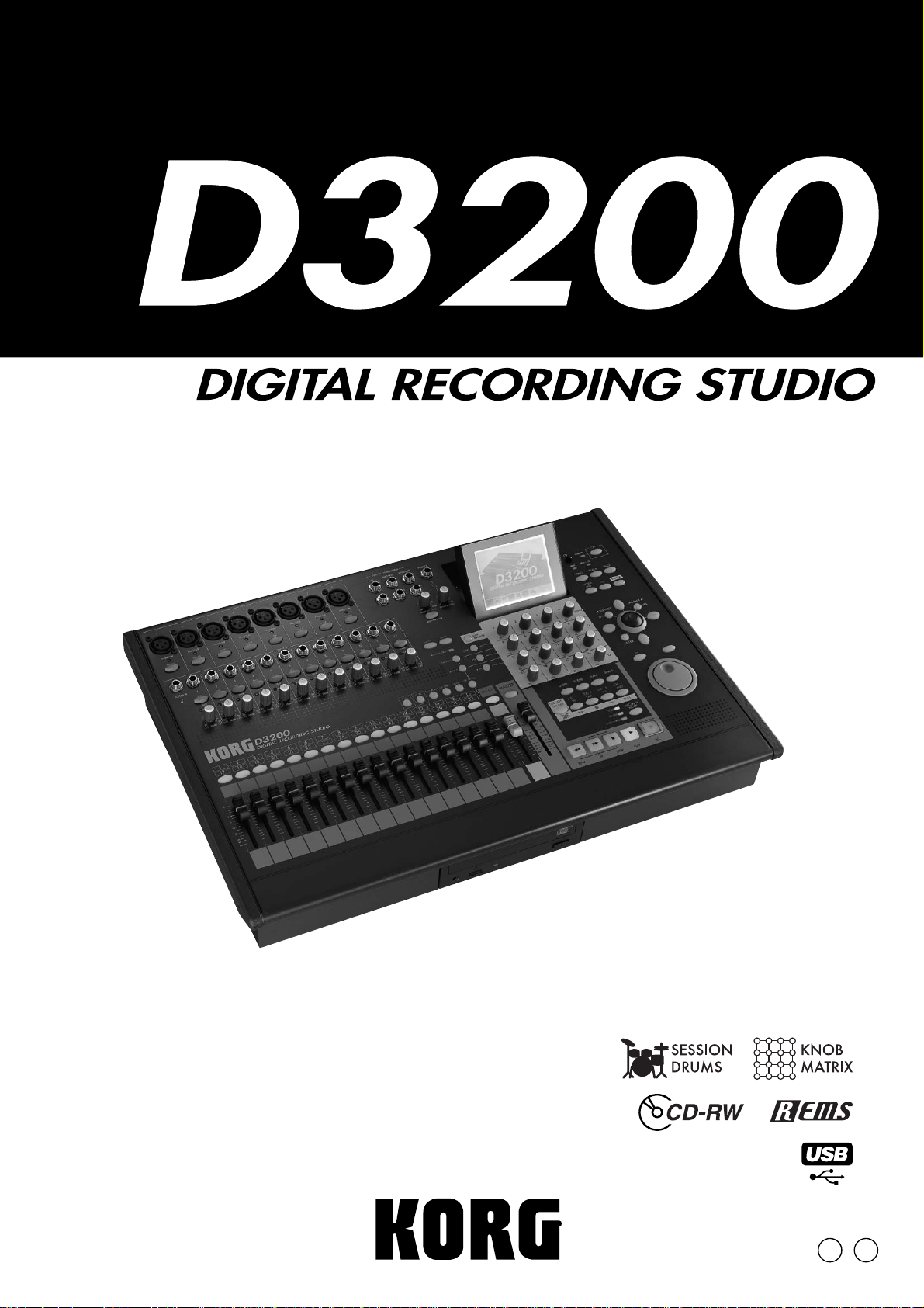
Owner’s Manual
E1
Page 2
IMPORTANT SAFETY INSTRUCTIONS
• Read these instructions.
•Keep these instructions.
• Heed all warnings.
•Follow all instructions.
• Do not use this apparatus near water.
• Mains powered apparatus shall not be exposed to dripping or
splashing and that no objects filled with liquids, such as vases,
shall be placed on the apparatus.
• Clean only with dry cloth.
• Do not block any ventilation openings . Install in accordance with
the manufacturer's instructions.
• Do not install near any heat sources such as radiators, heat
registers, stoves, or other apparatus (including amplifiers) that
produce heat.
• Do not defeat the safety purpose of the polarized or groundingtype plug. A polarized plug has two b lades with one wider than
the other. A grounding type plug has two blades and a third
grounding prong. The wide blade or the third prong are provided
for your safety. If the provided plug does not fit into your outlet,
consult an electrician for replacement of the obsolete outlet. (for
U.S.A. and Canada)
• Protect the power cord from being walked on or pinched
particularly at plugs, convenience receptacles, and the point
where they exit from the apparatus.
• Only use attachments/accessories specified by the manufacturer .
•Unplug this apparatus during lightning storms or when unused
for long periods of time.
•Turning off the power switch does not completely isolate this
product from the power line so remove the plug from the socket if
not using it for extended periods of time.
• Install this product near the wall socket and keep the po w er plug
easily accessible.
•WARNING—This apparatus shall be connected to a mains
socket outlet with a protective earthing connection.
• Refer all servicing to qualified service personnel. Servicing is
required when the apparatus has been damaged in any way,
such as power-supply cord or plug is damaged, liquid has been
spilled or objects have fallen into the apparatus , the apparatus
has been exposed to rain or moisture, does not operate normally,
or has been dropped.
• Do not install this equipment on the far position from wall outlet
and/or convenience receptacle.
• Do not install this equipment in a confined space such as a box
for the conv eyance or similar unit.
• Use only with the cart, stand, tripod, bracket, or table specified by
the manufacturer , or sold with the appar atus . When a cart is
used, use caution when moving the cart/apparatus combination
to avoid injury from tip-over.
The lightning flash with arrowhead symbol
within an equilateral triangle, is intended to
alert the user to the presence of uninsulated
“dangerous voltage” within the product's
enclosure that may be of sufficient magnitude
to constitute a risk of electric shock to persons.
The exclamation point within an equilateral
triangle is intended to alert the user to the
presence of important operating and
maintenance (servicing) instructions in the
literature accompanying the product.
CAUTION
Danger of explosion if battery is incorrectly replaced.
Replace only with the same or equivalent type.
THE FCC REGULATION WARNING (for U.S.A.)
This equipment has been tested and found to comply with the limits
for a Class B digital de vice, pursuant to P art 15 of the FCC Rules.
These limits are designed to provide reasonable protection against
harmful interference in a residential installation. This equipment
generates, uses, and can radiate radio frequency energy and, if not
installed and used in accordance with the instructions, may cause
harmful interference to radio communications. However, there is no
guarantee that interference will not occur in a particular installation.
If this equipment does cause harmful interference to radio or
television reception, which can be determined by turning the
equipment off and on, the user is encouraged to try to correct the
interference by one or more of the follo wing measures:
• Reorient or relocate the receiving antenna.
• Increase the separation between the equipment and receiver .
• Connect the equipment into an outlet on a circuit different from
that to which the receiver is connected.
• Consult the dealer or an experienced radio/TV technician for
help.
Unauthorized changes or modification to this system can void the
user’s authority to operate this equipment.
CE mark for European Harmonized Standards
CE mark which is attached to our company’s products of A C mains
operated apparatus until December 31, 1996 means it conforms to
EMC Directive (89/336/EEC) and CE mark Directive (93/68/EEC).
And, CE mark which is attached after January 1, 1997 means it
conforms to EMC Directive (89/336/EEC), CE mark Directive (93/
68/EEC) and Low Voltage Directive (73/23/EEC).
Also, CE mark which is attached to our company’ s products of
Battery operated apparatus means it conforms to EMC Directive
(89/336/EEC) and CE mark Directive (93/68/EEC).
Page 3
Handling of the internal hard disk
Do not apply physical shock to this device. In particular, you must never move this device or apply physical shock while the power is turned on. This can cause
part or all of the data on disk to be lost, or may damage the hard disk or interior components.
When this device is moved to a location where the
temperature is radically different, water droplets may
condense on the hard disk. If the device is used in this
condition, it may malfunction, so please allow several
hours to pass before operating the device.
Do not turn the power on and off repeatedly. This may
damage the D3200.
This device begins to access the hard disk immediately after the power is turned on.
Never turn off the power while the HDD access indicator is lit or blinking. Doing so can cause all or part of
the data on hard disk to be lost, or may cause malfunctions such as hard disk damage.
If the hard disk has been damaged due to incorrect
operation, power failure, or accidental interruption
of the power supply, a fee may be charged for
replacement even if this device is still within its
warranty period.
COPYRIGHT WARNING
This professional device is intended only for use
with works for which you yourself own the copyright, for which you have received permission from
the copyright holder to publicly perform, record,
broadcast, sell, and duplicate, or in connection with
activities which constitute “fair use” under copyright law. If you are not the copyright holder, have
not received permission from the copyright holder,
or have not engaged in fair use of the works, you
may be violating copyright law, and may be liable
for damages and penalties. If you are unsure about
your rights to a work, please consult a copyright
attorney.
FOR ANY INFRINGEMENT COMMITTED
THROUGH USE OF KORG PRODUCTS.
KORG TAKES NO RESPONSIBILITY
Data handling
Incorrect operation or malfunction may cause the contents of
memory to be lost, so we recommend that you save important data on a CD or other media. Please be aware that Korg
will accept no responsibility for any damages which may result from loss of data.
Also, when digitally recording copyrighted audio material
from a DAT or CD etc., you must obtain permission for use.
Please be aware that Korg will accept no responsibility for
any copyright violations which may occur through your use
of this product.
* Company names, product names, and names of for-
mats etc. are the trademarks or registered trademarks
of their respective owners.
iii
Page 4

OK
Cautions when using the CD-R/
RW drive
• During CD reading and writing operations, keep the unit
in a horizontal position.
• Do not use the unit in extremely cold or hot locations.
• Do not use the unit in extremely humid locations.
• Do not use the unit in dusty or smoky locations.
• Do not subject the unit to vibration or strong physical
shock. In particular, this unit is vulnerable to shock during
CD reading and writing operations.
• Normally, you will be able to open the CD tray by pressing the eject button. However if this fails, you can forcibly
eject the tray by inserting a thin object (such as a straightened paper clip) into the emergency eject hole.
• Do not store the unit in hot or humid locations.
• Never touch the focusing lens.
• Do not use commercially available lens cleaners.
• Do not transport the unit with a disc left in the tray.
• Do not leave the unit with the disc tray open.
CD-R/RW handling
Please observe the following points when handling discs.
Failure to observe these points may cause problems such as
data not being written correctly, loss of recorded data, or
drive malfunction.
• Do not leave discs in direct sunlight, or in locations of
high temperature or high humidity.
• Do not touch the surface of a disc. Hold a disc by its
edges.
• Remove dust or dirt from the surface of a disc. To remove
dust, use an air duster or cleaner.
• Do not affix labels to a disc, or write on a disc in locations
other than specified.
• Do not use chemicals or detergent to wipe a disc.
• Do not bend or drop a disc.
Responsibility for loss of data
Korg Corporation will accept no responsibility for any damages (direct or indirect, whether sustained by the customer or
by a third party) resulting from loss of or damage to data
written on a CD-R or CD-RW disc.
Printing conventions in this
manual
Faders, knobs, and keys on the panel
In this manual, “faders,” “knobs,” and “keys” refer to
controls on the panel. The names shown on the panel are
printed in boldface in the manual.
Examples: MASTER fader, TRIM knob, REC/PLAY key
Items in the LCD screen
“Buttons” and “dialog boxes” are displayed in the LCD
screen. The names shown in the screen are printed in
boldface in the manual.
Items printed in “
names shown in the LCD screen.
Examples:
page
Other items printed in boldface
Boldface is also used to indicate the names of non-
selectable parameters shown in the LCD screen, or to
indicate content in the text that we wish to emphasize.
Steps (1) (2) (3) ...
Steps in a procedure are indicated as (1) (2) (3) ...
(
→
p.
■■
)
This indicates a reference page within this manual.
, ,
These symbols respectively indicate points of caution,
notes of advice, or examples.
…, “XX” tab page
This refers to a page shown in the LCD screen. To access
this page, press the top panel … key, and then click the
“XX” tab in the LCD screen (
You can also use the panel
to move between tab pages.
…, …
, “XX” tab page
The top panel MIXER key and CD key display a page
jump menu in the LCD screen before the tab pages
appear, so click the page button (
the “XX” tab (
key will take you back to the page jump menu screen.
boldface ” are parameters or tab page
button, Rename dialog box, “SetUp” tab
→
p.13).
√
TAB PAGE/TAB PAGE
→
p.13) and then click
→
p.13). Pressing the MIXER key or CD
®
keys
iv
LCD screens
The parameter values shown in the LCD screens printed
in this manual are explanatory examples, and may not
necessarily match the displays that appear on your
D3200.
Page 5

Table of Contents
IMPORTANT SAFETY INSTRUCTIONS...............ii
Handling of the internal hard disk ...................iii
Data handling.................................................iii
COPYRIGHT WARNING...................................iii
Cautions when using the CD-R/RW drive .........iv
Printing conventions in this manual..................iv
Introduction ...................................1
Included items..................................................1
Before using the D3200 for the first time........ 1
Power on/off...................................................1
Setting the calendar .........................................2
Connection example.........................................3
Main features ............................................... 4
Parts and their function................................. 6
Top panel ........................................................6
Rear panel.....................................................11
About the CD-R/RW drive ..............................12
Items and functions in the LCD screen........... 13
Basic operation........................................... 15
Examples of operation ...................................17
5. Recording.................................................25
Preparations for recording ...............................25
Start recording....................................................26
6. Playback..................................................26
Step 3: Overdubbing ...................................27
1. Recording.................................................27
Preparations for recording ...............................27
Start recording....................................................27
2. Playback..................................................27
Step 4: Mixdown and mastering ..................28
1. Applying effects and EQ to individual
channels................................................... 28
Applying effects to individual channels/tracks
(Insert Effect) ......................................................28
Applying EQ to each channel/track...............28
Adjusting the pan ..............................................29
Using the channel/track sends to apply effects
(Master Effects)...................................................29
Selecting a master effect....................................29
Adjusting the Master Effect 1 Send amount for
each track ............................................................30
Checking and adjusting the master effect......30
2. Applying Final (or mastering) effects and EQ to
the entire song..........................................31
Set the meters to display the post fader
levels....................................................................31
Applying an effect to the master bus
(Final Effect)........................................................31
Applying EQ to the master bus (Master EQ).32
3. Recording the master track........................33
4. Writing to a CD ........................................34
Saving your song...........................................34
Quick Start ..................................18
Step 1: Preparations ................................... 18
1. Connections..............................................18
2. Turn the D3200 on....................................18
3. Listen to the demo song.............................19
Step 2: Quick recording .............................. 20
1. Create a new song....................................20
2. Name the song .........................................20
3. Connect your audio sources to the mixer
inputs.......................................................21
Connect mics and instruments to the INPUT
jacks......................................................................21
Assign the inputs to channels..........................22
4. Adding EQ and EFFECTS............................23
Applying EQ to the input sound.....................23
Applying effects to the input sound...............24
Operation....................................35
Song, Locate................................................35
1. Selecting/creating a song..........................35
1-1. Creating a new song.........................35
1-2. Renaming a song..............................36
Using the name library ................................36
1-3. Selecting a song................................36
Selecting a song from the song list.............36
Selecting a song from another song drive
2. Location ...................................................37
2-1. Switching the counter display............37
Switching the information display area ....37
2-2. Moving to a different location............38
Using the counter to move ...............................38
Using the FF and REW keys to move .............38
Moving to a point later in the song
(fast-forward) ................................................38
Moving to a point earlier in the song
(rewind)..........................................................38
..36
v
Page 6

Moving to the beginning/end of the song.... 38
Moving to the beginning of the song ........ 38
Moving to the end of the song ................... 38
Using the Locate keys to move........................ 38
Assigning locations to the Locate keys..... 38
Moving to a location registered to a Locate
key .................................................................. 38
Moving using assignable Marks ..................... 38
Registering a mark....................................... 38
Moving to the location assigned to a
mark ............................................................... 39
Using the MARK keys to move.................. 39
Deleting a mark............................................ 39
Renaming a mark......................................... 39
2-3. Finding a precise location (SCRUB).....40
Finding a zero-cross point .......................... 40
3. Song editing .............................................41
3-1. Song editing procedure.....................41
Copying a song.................................................. 41
Moving a song ................................................... 41
Deleting a song.................................................. 41
Protecting a song............................................... 42
Protect On...................................................... 42
Protect Off ..................................................... 42
Saving a song..................................................... 42
3-9. Solo settings.....................................48
Soloing just one channel.............................. 48
Soloing more than one channel.................. 48
Cancelling solo.............................................. 48
Sending the soloed audio from the master
bus .................................................................. 48
3-10. Muting a channel.............................48
3-11. Mixer Setup.....................................49
Storing a mixer setup................................... 49
Recalling a mixer setup ............................... 49
4. Storing/recalling a scene ..........................50
4-1. Storing a scene.................................50
4-2. Recalling a scene..............................50
4-3. Renaming a scene.............................50
4-4. Deleting a scene ...............................50
4-5. Editing and overwriting a scene.........51
4-6. Specifying parameters that will be
disabled for an individual scene........51
4-7. Specifying parameters that will be
disabled for all scenes....................... 51
4-8. Controlling scenes via MIDI ...............51
MIDI output..................................................51
MIDI input..................................................... 51
Mixer..........................................................42
1. Inputting audio to the mixer ......................42
1-1. Analog input.....................................42
Inputting audio from a guitar .................... 42
Using the tuner............................................. 43
1-2. Digital input......................................44
Inputting the digital audio signal from a MD
or DAT........................................................... 44
1-3. Sub input..........................................44
2. Audio outputs from the mixer....................44
3. Mixer settings ...........................................45
3-1. Adjusting the volume.........................45
Adjusting the volume level of each
channel........................................................... 45
Inputting a source at the maximum level
Adjusting the overall volume level ........... 45
3-2. Adjusting the pan..............................45
3-3. EQ (Equalizer)...................................45
Channel EQ........................................................ 45
Applying EQ to an audio input ................. 45
Applying EQ to the playback..................... 46
Master EQ........................................................... 46
3-4. EQ library (Storing and recalling EQ
settings)............................................46
Storing EQ settings....................................... 46
Recalling EQ settings................................... 46
3-5. Pairing..............................................46
3-6. Group settings...................................47
Fader groups................................................. 47
CH ON groups.............................................. 47
3-7. Monitor settings ................................47
3-8. Adjusting the cue level.......................48
.. 45
5. Automation ..............................................52
5-1. Scene automation.............................52
Using scene automation..............................52
Storing a scene at a different location........ 52
Editing the location of a stored scene........ 52
5-2. Event automation..............................52
Recording mixer operations ....................... 52
Playing back the events............................... 53
Editing events ............................................... 53
Effects......................................................... 54
Effect type and size ........................................... 54
How DSP power is allocated to the effects.... 54
1. Using insert effects....................................55
1-1. Applying insert effects during
recording..........................................55
1-2. Applying insert effects during
playback..........................................55
2. Using master effects..................................55
3. Using the final effect .................................55
4. Editing the effects......................................56
Editing the effect parameters........................... 56
For an insert effect........................................ 56
For a master effect or final effect................ 56
Storing an effect program................................. 56
5. Controlling effects from an external device 57
6. Using external effects................................57
Session Drums™ .........................................58
1. Listening to drum patterns......................... 58
If you’ve selected Metronome as the
group.............................................................. 58
vi
Page 7

2. Creating a drum track for an entire song
(Pattern Map)............................................58
Auditioning the pattern map......................59
3. Recording with Session Drums...................59
Recording additional tracks as you listen to the
drum track ..........................................................59
Recording patterns on a track..........................59
Recording Session Drums to a channel
track................................................................59
Recording directly to the master track ......60
4. Editing a drum kit .....................................60
Selecting a drum kit...........................................60
Editing the sound of a drum kit .................60
Preserving drum kit changes and drum
sound edits.....................................................60
5. Pattern maps ............................................61
Creating a pattern map.....................................61
Editing a pattern map .......................................62
Inserting a new event into the pattern
map.................................................................62
Replacing an event .......................................62
Overwriting a portion of an existing
event ...............................................................62
Deleting an event..........................................62
6. Tempo.......................................................62
Playing the entire song at the same tempo
Changing the tempo during the song........63
The Song Guide function..................................63
.62
6-1. Tempo track.......................................63
Recording MIDI Clock data from an external
MIDI sequencer, and using it as the tempo
track................................................................63
Tap tempo......................................................63
6-2. Pattern map tempo ............................64
Recorder..................................................... 64
1. Recording.................................................64
Bounce recording...............................................64
1-1. Basic recording .................................64
1-2. Switching virtual tracks......................65
1-3. Overdubbing (Recording additional
tracks during playback).....................65
1-4. Trigger recording ..............................65
1-5. Punch-in Recording
(Re-recording a specific area).............66
Manual punch-in/out....................................... 66
Using a foot switch for manual punch-in/
out...................................................................66
Auto punch-in/out............................................ 66
Loop recording................................................... 67
1-6. Creating a master track .....................67
2. Playback ..................................................68
2-1. Normal playback ..............................68
2-2. Loop playback ..................................68
2-3. Playing back an album CD project .....69
3. Track editing.............................................69
Registering the edit region..........................69
3-1. Track editing procedures ...................69
Copy a track (CopyTrk)....................................69
Copying tracks within the same song........69
Using the clipboard to copy data to another
song.................................................................70
Insert blank space (InsertTrk) ..........................71
Erase a track (EraseTrk)....................................72
Delete a track (DeleteTrk).................................72
Deleting track data........................................72
Deleting all data of a track...........................72
Exchange tracks (SwapTrk)..............................73
Reverse a track (ReverseTrk)............................73
Optimizing a track (OptimizeTrk) ..................74
Expand/compress a track (ExpCmpTrk).......74
Copy an entire track/Copying to a Virtual track
(CopyWholeTrk)................................................75
Copying to a virtual track............................75
Exchange two entire tracks (SwapWholeTrk)
Swapping entire tracks.................................76
Fade-in/fade-out (FadeTrk).............................76
Creating a fade-in .........................................76
Creating a fade-out.......................................77
Boosting the maximum volume to the specified
level (Normalize: NormalizeTrk) ....................77
Eliminating noise (NoiseReduction)...............78
Erasing punch noise (ErasePunchNoise) .......78
Erase a silent region (EraseSilence).................79
76
4. Naming a track ........................................79
CD..............................................................79
1. Track At Once...........................................79
2. Disc At Once.............................................80
2-1. Album CD Project..............................80
2-2. Creating a live CD.............................82
3. Ripping a CD.............................................82
Data ...........................................................83
1. Backing up and restoring..........................83
1-1. Backing up .......................................83
Backing up 1Song .........................................83
Backing up All Data .....................................84
Backing up User Data...................................84
1-2. Restoring backed-up data .................85
2. Audio files................................................86
2-1. Importing an audio file......................86
Importing an audio track into the beginning
of a track.........................................................86
Importing an audio file into the middle of a
track ................................................................87
2-2. Exporting an audio file......................87
Exporting an audio file ................................87
Exporting multiple audio files....................88
3. Drive and data compatibility with the Digital
Recording Studio series............................. 88
Using D32XD and D16XD data ..................88
Using D3200 data on a different model.....88
Using data from a different model on the
D3200..............................................................88
vii
Page 8

Drive...........................................................89
1. Specifying the drive size............................89
1-1. Partitioning the hard drive into separate
song drives (Partitions) ......................89
1-2. Specifying the PC drive size ...............89
2. Renaming a song drive .............................90
3. Checking the hard disk..............................90
4. Formatting the hard disk ...........................90
5. Load system..............................................91
6. Creating a system recovery CD..................91
7. Drive capacity...........................................91
To keep only the audio data that you are
actually using................................................ 91
To erase A and B that remain from the first
take, and recover disk space....................... 92
Deleting the Undo data.................................... 92
Sharing event data ............................................ 92
8. PC drive....................................................92
Checking, renaming, or deleting files.........92
USB.............................................................93
1. Saving/loading.........................................93
Windows users (Windows Me/2000 or later)
Macintosh users (Mac OS9.0.4 or later).......... 93
.93
MIDI............................................................94
1. MIDI connections.......................................94
MIDI channel settings....................................... 94
2. MIDI messages used by the D3200 ............94
About the MIDI implementation chart.......... 94
3. Using MIDI................................................94
Controlling the D3200 from a MIDI
sequencer............................................................ 94
Synchronizing two D3200 units................. 95
Using MIDI to control the mixer..................... 95
Upgrading the system..................................96
1. Downloading the operating system............96
Upgrading via CD-ROM/R/RW............... 96
Upgrading via USB...................................... 96
2. Upgrading the system ...............................96
Using a recovery CD to recover the system....96
Preserving non-system data when you
recover ........................................................... 96
If an error appears and the recovery is
unsuccessful.................................................. 96
ClickPoint calibration ...................................97
Reference .................................... 98
Counter.......................................................98
Counter display ........................................98
Rename ......................................................99
Editing a name .........................................99
1. METER.....................................................99
Meter/Track View.....................................99
2. MIXER...................................................100
2a. CH INPUT/SubMixer..............................101
2a-1. Channel Assign..............................101
2a-2. Sub Mixer 1–4...............................101
2a-3. Sub Mixer 5–8...............................101
2a-4. Sub Mixer 9–12.............................101
2b. PAIR/GROUP ........................................102
2b-1. Channel Pair .................................102
2b-2. Fader Group..................................102
2b-3. Channel On Group ........................102
2c. FADER/PAN/AUTOMATION...................103
2c-1. Fader Pan......................................103
2c-2. Automation.................................... 103
2c-3. Event List........................................104
2c-4. Edit Scene......................................105
2c-5. Scene Filter ....................................106
2c-6. Mixer View....................................106
2d. EQ/ATT/PHASE.....................................107
2d-1. EQ/ATT.........................................107
2d-2. EQ Library.....................................107
2d-3. Phase............................................108
2d-4. Master EQ..................................... 108
2e. SEND (EFF/AUX/REC).............................109
2e-1. Effect 1 Send..................................109
2e-2. Effect 2 Send..................................109
2e-3. Aux1 Send ....................................109
2e-4. Aux2 Send ....................................109
2e-5. Rec Send .......................................110
2f. SOLO/MONITOR....................................110
2f-1. Solo...............................................110
2f-2. Monitor..........................................111
2f-3. Cue Level .......................................111
2g. MIXER SETUP.........................................111
3. CH VIEW............................................... 112
3-1. Ch View..........................................112
3-2. Channel Routing View .....................112
viii
4. EFFECT..................................................113
4-1. Effect Routing ..................................113
4-2. Insert EFF.........................................114
Page 9

4-3. Master EFF1.....................................115
4-4. Master EFF2.....................................116
4-5. Final EFF..........................................116
5. SEND.................................................... 116
6. EQ........................................................ 116
7. PAN..................................................... 116
8. SONG.................................................. 117
9. SYSTEM/MIDI ....................................... 119
9-1. Control............................................119
9-2. Disk Utility.......................................120
9-3. Edit PC File.......................................122
9-4. Backup............................................123
9-5. Restore............................................123
9-6. MIDI/MMC ......................................124
10. TRACK................................................ 126
10-1. Virtual Track 1–32 .........................126
10-2. Master Track..................................126
10-3. Edit Track ......................................126
10-4. Import File.....................................135
10-5. Export File .....................................136
Effect parameters .......................150
Algorithm list.............................................150
Program list ..............................................150
About the effect algorithms ..........................152
Stereo-type.............................................152
Category: Reverb&Delay
Reverb/delay-type effects..............................152
Category: Modulation&Pitch
Modulation/Pitch-type effects ......................155
Category: Dynamics&Filter
Dynamics/Filter-type effects .........................156
Category: SFX&etc
SFX/Etc effects.................................................158
Monaural-type........................................159
Category: Reverb&Delay
Reverb/delay-type effects..............................159
Category: Modulation&Pitch
Modulation/Pitch-type effects ......................160
Category: Dynamics&Filter
Dynamics/Filter-type effects .........................161
Category: SFX&etc
SFX/Etc effects.................................................162
Category: Multi
Multi Effect .......................................................163
11. CD...................................................... 137
11a. Album CD............................................138
11b. Track at once.......................................139
11c. CD PLAYER...........................................140
12. UNDO................................................ 141
13. TUNER................................................ 141
14. SESSION DRUMS ................................ 142
14-1. Session Drums ...............................142
14-2. Drums Track Mixer.........................143
14-3. Pattern Map...................................144
14-4. Tempo Track..................................145
15. STORE................................................ 145
16. SCENE................................................ 145
17. MARK................................................. 145
18. SCRUB................................................ 146
19. LOC 1/IN, … LOC 4/END ................... 147
MIXER Navigation Tools ...............................147
20. REC/PLAY MODE ................................ 147
20-1. Rec Mode ......................................147
20-2. Play/Stop Mode.............................149
21. Transport keys.................................... 149
Appendices................................164
Troubleshooting.........................................164
Power does not turn on................................164
Nothing appears in the display ....................164
Vertical lines are visible in the display ..........164
No sound....................................................164
Faders don’t work .......................................164
Can’t record................................................165
Can’t use digital input..................................165
Playback level is lower than the level during
recording ...............................................165
The input or recorded sound is noisy or
distorted................................................. 165
Effects do not apply .....................................165
Session Drums.............................................166
A key does not function when pressed.......... 166
MIDI............................................................166
CD-R/RW....................................................167
Audio files...................................................167
USB.............................................................167
Startup........................................................167
Various messages......................................168
Confirmation messages...................................170
Serious error messages....................................170
ix
Page 10

More about drives and files........................171
Drives..........................................................171
CD-R/RW drive ......................................... 171
PC (USB) drive............................................ 171
Audio CDs and files......................................172
Audio CDs........................................................ 172
Playing an audio CD.................................. 172
Creating an audio CD................................ 172
Files.................................................................... 172
Writing......................................................... 172
Loading........................................................ 173
Specifications ............................................174
Main sections ................................................... 174
Principal specifications................................... 174
Analog/digital input and output
specifications.................................................... 175
Included items ................................................. 175
Separately sold options .................................. 175
Various lists...............................................176
Drum Pattern List..........................................176
EQ Library List .............................................177
Name Library List.........................................177
Demo Song List............................................177
Shortcut keys.............................................178
Glossary....................................................179
Index ........................................................184
Block diagram...........................................188
MIDI implementation chart .........................189
x
Page 11
Introduction
Thank you for purchasing the Korg D3200 Digital Recording Studio.
To take full advantage of the D3200’s functions, and to enjoy trouble-free use,
please read this manual carefully and use this product only as directed. Keep this
manual in a safe place for future reference.
Included items
Make sure that the following included items are present.
• Owner’s Manual (this document) • Power cable
Before using the D3200 for the first time
Important
Please observe the following points when using the D3200.
Introduction
for the first time
Before using the D3200
Power on/off
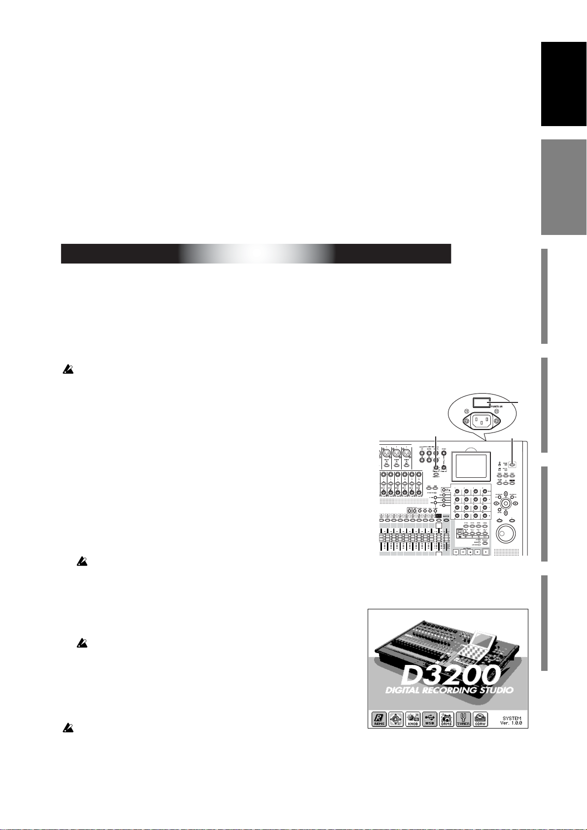
The D3200 is a precision instrument, similar to a personal computer, equipped
with an internal hard disk drive and a CD-R/RW drive. When turning the power
on and off, follow the procedures shown below.
Before you turn on the power, make sure that the power cable is firmly plugged into the D3200
and into an AC outlet.
● Power-on
(1)Lower the D3200’s MONITOR LEVEL knob to the
–∞ position. Set the volume controls of your external equipment to their lowest position.
(2)Turn on the power of external input devices such as key-
boards that are sending audio to the D3200.
(3)Turn on the main power switch (POWER ON) located on the
rear panel of the D3200.
The STANDBY indicator will light. The D3200 is now in the
“standby” condition.
A certain amount of time will be required from when you turn on the main power until the
STANDBY indicator lights.
(4)Press the power (ON) key located on the top panel to turn
the D3200 on.
The opening screen will appear in the LCD, and then the
SONG page will appear.
A certain amount of time from when you press the power-on key until
the opening screen appears.
The next time you turn the power on, the song that had been
selected prior to the previous power-off will be selected.
(5)T urn on the power of your external output devices, such as
the monitor system to which the D3200 is sending audio.
If the power is turned off accidentally while the D3200 is being used, the
D3200 itself or its internal hard disk drive may be damaged.
The opening screen (D3200)
Main featuresParts and their functionItems and functions in the
(3)
(4)(1)
LCD screen
Basic operation
1
Page 12
● Power-off
(1)Lower the D3200’s MONITOR LEVEL knob to the –∞ position.
(2)Turn off any devices connected to the D3200’s outputs, such as your moni-
tor system.
(3)Hold down the D3200’s power (ON) key (for 2–3 seconds)
and the shutdown LCD screen appear.
If you click the Yes button (or press the panel YES key) in the
LCD screen, the song will be saved automatically, and the
D3200 will enter the standby state. This process is called
“shutdown.”
If you click the No button (or press the panel YES key), you will return to the
previous screen.
(4)Press the main power switch (POWER ON) located on the rear panel of the
D3200 to turn off the power.
(5)Turn off any devices (such as keyboards) connected to the D3200’s inputs.
When turning the power off, you must perform the shutdown process. Never turn off the main
power switch or disconnect the power cable before shutdown has been completed.
If you turn off the main power switch or disconnect the power cable before shutdown has been
completed, data or user settings will be lost, and the hard disk may be damaged.
The audio you record into the D3200 and the mixer and effect settings you make are automatically saved when you select a song or perform the shutdown process.
Perform the
If you will not be using the D3200 for an extended period of time, turn off the main power switch
on the back of the D3200.
shutdown
process when you have finished all activities such as playback or recording.
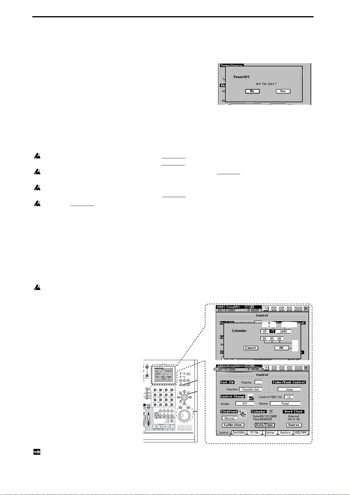
Setting the calendar
When a song is saved, the file is time-stamped with the date and time provided
by the internal calendar.
You will need to set the calendar the first time you use the D3200 after purchasing
it, if the main power switch has been turned off, or if you need to change the calendar time for any other reason.
If you haven’t set the calendar, the calendar area (A) of the information display is shown in
gray.
(1)Press the SYSTEM/MIDI key.
(2)Click the “Control” tab.
(3)Click the Date/Time button to
open the Calendar dialog box.
(4)Click the four-digit year field to
highlight it.
(5)Use the value dial or the +/– keys
to set the year.
(6)Click the month field at left to
highlight it, and set the month in
the same way.
(7)In the same way, set the day, hour
(in 24-hour format), minute, and
second areas of the Date field.
(8)Click the OK button (or press the
panel YES key) to apply the date
and time you specified.
The calendar clock continues to run when you power-off to the Standby mode. However, if you
turn off the main power switch, the calendar will need to be reset.
(A)
(1)
(8)
(5)
(6)
(7)
(2) (3)
(6) (7)
(4), (5)
(7)
(8)
2
Page 13
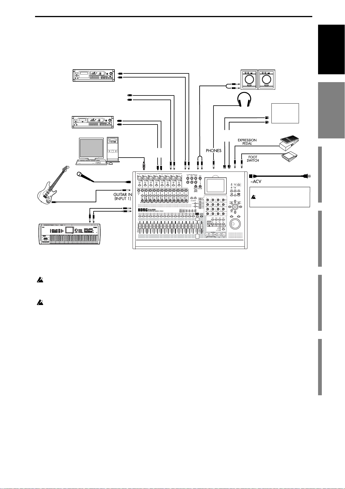
Connection example
This diagram shows typical connections when using the D3200.
Connect your equipment as appropriate for your system.
Guitar
Master recorder (Analog: cassette tape recorder, etc.)
Master recorder (Digital: DAT, MD, etc.)
Computer
Mic
OUTPUT
INPUT L/R
AUX
OUT
DIGITAL IN
DIGITAL OUT
S/P DIF
IN/OUT
USB
INPUT 1–8
INPUT 1–12
MASTER
OUT
MONITOR
OUT
MIDI
IN/OUT
Monitor speakers etc.
Headphones
Power supply connection
You must use the included
AC power cable
MIDI
sequencer
MIDI
OUT/IN
EXP-2
Foot controller
PS-1
Pedal switch
to the AC outlet
Introduction
for the first time
for the first time
Before using the D3200
Before using the D3200
Main featuresParts and their functionItems and functions in the
Keyboard
Cautions when making digital connections
If any of the synchronization settings of the D3200 do not match those of the connected device,
noise may occur. Turn down the faders or minimize the volume of your monitor speakers before
you change settings.
If you select a song that has a different sampling frequency, noise may occur when the change
occurs. Turn down your monitors before you make such a change.
LCD screen
Basic operation
3
Page 14

Main features
♦ 32-track digital multi-track recorder
The D3200 provides studio-quality sound with 64-bit internal processing, 24/16-bit recording and
playback, and 48 kHz/44.1 kHz uncompressed recording.
When using 48 kHz/44.1 kHz sampling and 16-bit depth
Maximum simultaneous recording/playback 16* tracks/32 tracks
When using 48 kHz/44.1 kHz sampling and 24-bit depth
Maximum simultaneous recording/playback 12** tracks/16 tracks
*16 channels is the maximum, combining 12 analog inputs, + 2 digital inputs (S/P DIF L,R), + 2 Session Drums (L,R).
**12 channels using any combination of analog inputs, digital inputs and Session Drums.
Each track (including the master track) has eight virtual tracks, allowing you to use a total of 256 +
16 tracks for each song.
1 The number of simultaneously recordable tracks will be different when you use punch recording.
❖
❖1
❖1
♦ Session Drums™
The D3200 is equipped with Korg’s unique Session Drums™. Using the Session Drums™ to control the internal drum sounds you can play, create, modify and record a drum track for your song.
The Session Drums™ even have their own dedicated fader. For added realism, you can access a
number of real-time control elements - such as shuffle, dynamics and humanize - all using the convenient Knob Matrix.
♦ XLR input jacks with +48V phantom power, analog inputs, dedicated guitar input jack,
and digital connectors
To maximize the benefit of the D3200’s full-digital pr ocessing, all of the analog inputs use high-performance balanced preamps.
The eight +48V phantom-powered XLR input jacks contain high-performance mic preamps. Each
of the phantom power supplies can be switched on/off individually, so you are free to mix condenser mics and dynamic mics.
All phone jack inputs (except for the guitar input jack) are the TRS balanced type. Unbalanced
inputs may also be connected to these jacks. A wide range of audio sources can be connected, ranging from mic level all the way up to +4 dBu, exceeding normal professional levels. A dedicated guitar input jack is also provided.
The S/P DIF digital input supports sampling frequencies of 48 kHz/44.1 kHz, and 24- and 16-bit
depths.
♦ Mixer section provides four-band EQ on each channel/track and four-band master EQ
The 44-channel 12-bus mixer section provides four-band full parametric EQ on mixer channels 1–
24, and two-band shelving EQ on mixer channels 25–32 and on the sub-mixer.
The EQ applied to the input during r ecording is independent from the EQ applied to the track during playback, so there is no danger of applying the same EQ twice – a problem that often occurs on
MTR units containing conventional analog mixers.
Four-band full parametric equalization is provided for the master EQ, allowing you to make
detailed adjustments to the tone during mastering.
♦ 100 mixer scene memories, plus MIDI control of mixer parameters
For each song, you can store one hundred scenes containing the fader, EQ, pan, and effect settings
of the mixer section. Scenes can be easily recalled when desired as general-purpose settings. You
can also use MIDI to switch scenes, and to transmit and receive mixer parameters such as fader
and pan.
♦ Scene and event mixer automation
Scene changes and mixer events such as fader movements and panning operations can be recorded
and reproduced according to elapsed playback time. Scene automation can be used to switch
scenes automatically.
4
Page 15
♦ Powerful modeling effects featuring real-time control via the Knob Matrix
The built-in effects utilize Korg’s proprietary “ ” modeling technology to deliver precise and
powerful modeling sounds.
You can use the sixteen real-time controllers of the Knob Matrix to edit effect parameters quickly
and intuitively. The modeling effects include simulations of vacuum tube preamps, classic amps
and cabinets from ar ound the world, and mic simulators for vintage tube mics and modern studio
condenser mics.
♦ Three independent effect systems provide eleven simultaneous effects
You can use up to a total of eleven effects, each with internal 56-bit processing: 8 insert effects, 2
master effects, and 1 final effect.
For each effect, you can select an effect program created using one of 52 different effect algorithms
(combinations of basic effects).
The effect programs include 128 preset programs created by professional musicians and studio
engineers, and 128 user effect pr ograms that you can use to create, edit and store your own custom
effect settings.
In addition, each song has 32 editable song effect programs.
You can also control effects in real time from an external MIDI controller or from an expression
pedal (EXP-2, XVP-10: sold separately).
♦ Sophisticated digital editing tools
Non-destructive editing functions (possible only on digital recorders) allow you to perform
numerous edits without compromising the high audio quality. In addition to auto and manual
punch-in/out, there are Undo and Redo functions that allow you to audition the “before” and
“after” versions of any edit, before making it permanent. You can use Undo to retrace your steps
through the sixteen most recent recording or editing operations! A total of twelve types of track
editing operation are provided, including a convenient Time Expansion/Compression function
that lets you match up phrases of differing tempo after recording, and a Normalize function that
appropriately boosts the volume and increases the dynamic range of low-level recordings.
For each song you can assign one hundred markers (with names) and six locate points to keep
track of (and instantly access) the locations of all your edits.
Introduction
for the first time
Before using the D3200
Main featuresParts and their functionItems and functions in the
Main features
♦ Intuitive interface designed for ease-of-use
The D3200 is designed for enhanced usability and ease of operation. Controllers such as the centerclick ClickPoint™ and cursor keys can be used to quickly select parameters and tabs in the 320
240 pixel high-resolution LCD screen. The Knob Matrix is located below the high-resolution LCD
screen, and allows you to edit parameter values quickly, in real time and on the fly.
♦ Internal hard drive
A high-capacity hard disk drive is built-in, providing approximately three hours of recording time
per GB (16-bit, 44.1 kHz, single track recording).
♦ CD-R/RW drive for creating backup disk and audio CDs
You can use the CD drive to backup/restore song and effect data, import/export audio files, and
create audio CDs. You can also place an audio CD in the drive and use the CD Player function to
play it. You can create an audio CD either by writing songs individually using Track At Once;
or by using the Album CD Project and Disc At Once functions.
♦ USB connection lets you easily share files with your computer
The USB connector makes it easy to exchange data with your computer. You can connect the D3200
to your computer and partition a 2, 4, or 8 GB area of the D3200’s hard drive as a PC drive for sharing data.
What is ?
(Resonant structure and Electronic circuit Modeling System) is Korg’s proprietary technology for digitally
recreating the numerous factors that produce and influence a sound, ranging from the sound-production mechanisms of acoustic instruments and electric/electronic musical instruments, to the resonances of an instrument body
or speaker cabinet, the sound field in which the instrument is played, the propagation route of the sound, the electrical and acoustic response of mics and speakers, and the changes produced by vacuum tubes and transistors.
×
LCD screen
Basic operation
5
Page 16
Parts and their function
Top panel
18
19
78 9101112
6
1
2
3
4
5
1413
16
17
15
21
20
22
23
1 INPUT 1, INPUT 2...INPUT 12 jacks
Connect mic or line sources (such as keyboards) to these input jacks.
Both XLR jacks and balanced 1/4" TRS phone jacks are provided.
You may also connect unbalanced phone plugs to the 1/4" jacks.
You can use either XLR connectors or TRS phone connectors for INPUT 1 through 8.
If you need to supply phantom power to condenser mics, connect them to the XLR connector.
Each XLR jack can provide +48V phantom power for condenser mics. The LED located below each
XLR jack will light if phantom power is switched on for that jack.
2: HOT
1: GND
3: COLD
Phantom power LED
The balanced XLR jacks for INPUT 1–8 provide +48V phantom power for use by condenser mics; you can switch
this on/off independently for each channel.
Your equipment may be damaged if you connect or disconnect a condenser mic with phantom power turned on. You
must turn phantom power off before connecting or disconnecting condenser mics.
Balanced phone plug Unbalanced phone plug
COLD
GND
HOT
GND HOT
2 Phantom power switch
INPUT 1–8
jacks provide +48V phantom power so that condenser mics can be used. Phantom
power is supplied to the balanced XLR jacks, and can be selected independently for each channel.
Turn this switch on only for channels that use a condenser mic.
If a condenser mic is connected or disconnected with the phantom power switch on, damage to your equipment
may occur. For this reason, always turn the phantom power switch off before connecting or disconnecting a condenser mic.
If the phantom power switch is on, you must never connect any device other than a condenser mic. Doing so may
damage your equipment.
6
Page 17
3 GUITAR IN jack
You can plug a guitar or bass into this jack. The GUITAR IN jack shares the same audio path as the
INPUT 1 jack; if both jacks are connected to an audio source, the GUITAR IN jack will take priority.
This is an unbalanced 1/4" phone jack with 1 MΩ input impedance.
4PAD buttons
The pad will reduce the input level by 26 dB. The pad is on when the switch is pressed in. You can
extend the adjustable range of the
TRIM
knob by turning the pad on when using a line input.
Leave the pad switched off for a low-output device such as a mic or guitar.
5 TRIM knobs
These knobs adjust the input level. The markings indicate the input level.
Adjust the
TRIM
knob as appropriate for your input device so that the LED located at the upper
left of the knob does not light even at the maximum loudness.
The
TRIM
knob has a range of +4 to –34 dBu when
PAD
is on, or –22 to –60 dBu when
PAD
The input level will depend on the instrument or performance, but the approximate ranges are as
follows.
–60 – –40 dBu:
–30 dBu:
–10 dBu:
+4 dBu:
If the TRIM knob is raised when nothing is connected to the input, hum or noise may result. Keep the trim knob
at its lowest setting when the channel is not in use.
keyboards or studio equipment
mic input
guitar, bass guitar
consumer audio devices such as a CD player
6 AUX 1/2 jacks
These jacks output the external send audio signals from the mixer channels (→p.109). You can connect these to the input jacks of an external effect processor.
These are 1/4" unbalanced phone jack outputs.
is off.
Introduction
for the first time
Before using the D3200
Main featuresParts and their functionItems and functions in the
7 MASTER L/R jacks
These jacks provide the analog audio signal from the master bus, or the audio signals selected by
the
SOLO
function. You can select the solo source in
MIXER, SOLO/MONITOR, “Solo”
tab
page.
These jacks are primarily used to connect the D3200 to an external recording device. These jacks
provide an analog version of the audio being sent to the S/P DIF OUT jack.
These are 1/4" balanced/unbalanced TRS phone jack outputs.
8 MONITOR L/R jacks
Connect these jacks to your external monitor system. In
tab page (
output the same audio as the
→
p.47, 1 11) you can select the bus that will be monitor ed from these outputs. These jacks
PHONES
jacks.
MIXER, SOLO/MONITOR, “Monitor”
These are 1/4" balanced/unbalanced TRS phone jack outputs.
9 PHONES jack
A set of headphones can be connected to each of these jacks.
This is a 1/4" stereo phone jack.
The headphone output is the same signal as the
MONITOR L/R
jacks.
10 MONITOR LEVEL knob
This knob sets the volume level of the signal being sent from the
MONITOR L/R
jacks.
11 PHONES LEVEL knob
This knob adjusts the volume level of the signal being sent from the
PHONES
jack.
Parts and their function
LCD screen
Basic operation
12 MONITOR MUTE key
This switch mutes the audio output from the
off each time you press the key. The audio from the
MONITOR L/R
PHONES
jacks. The setting will alternate on/
jack will not be muted. This feature
is very useful if you are r ecor ding using a microphone, and do not want the microphone to pick up
the sound from your monitor speakers.
7
Page 18

13 1–16 key, 17–32 key
Use these keys to select whether the
channel faders, channel keys
, and LCD screen will be used
to operate channels 1–16 or channels 17–32. The key you select will light.
14 REC/PLAY key
Turn this key on (lit) and use the
channel keys
to switch each channel of the track recorder
between record and playback status. The status of the track will alternate each time you press its
channel key
. If the master track
channel key
is set to PLAY, all tracks will automatically be muted
(silent).
15 CH ON key
Turn this key on (lit) and use the
channel keys
to enable or disable each channel. You can use this
as a Mute function.
16 SOLO key
Turn this key on (lit) and use the
channel keys
to turn Solo on/off for each channel. You may turn
Solo on for more than one channel at a time.
17 CH SELECT key
Turn this key on (lit), and use the
View,” “EQ/ATT,”
or send tab pages.
channel keys
to specify the track that will be selected in the
18 Channel keys (1–16/17–32)
These keys switch the status of each channel.
If the 1–16 key is lit, these keys correspond to channels 1 through 16; if the 17–32 key is lit, these
keys correspond to channels 17 through 32.
CH SELECT key on:
SOLO key on:
Use these keys to select the soloed channels (lit if selected).
CH ON key on:
REC/PLAY key on:
Use these keys to select channels (lit if selected).
Switch each channel between enabled/disabled (muted) (lit if enabled).
Switch each channel between r ecor ding/playback status (red for record, gr een
for playback).
“Ch
19 Channel faders (1–16/17–32)
These faders specify the recording/playback volume of each channel. If the 1–16 key is lit, the faders control channels 1–16; if the 17–32 key is lit, the faders control channels 17–32.
20 DRUMS fader, DRUMS key
This fader adjusts the recording/playback volume of the Session Drums. When the
DRUMS
key
located above the fader is on (lit), you can use the Session Drums to produce a rhythm during
recording or playback.
21 MASTER fader, MASTER key
This fader adjusts the overall volume of all channels. When recording the master track, this sets the
recording level of the recording-destination track. Each time you press the
MASTER
key located
above the fader, the status will alternate between record (lit red)/play (lit green)/off (dark).
Normally, you will leave the MASTER fader set to 0 dBu while recording on the individual tracks, and use the
channel faders to adjust the mix so the output does not distort.
22 LCD screen
This displays information such as the recording/playback volume (level meters), time data (location), and various parameters. You can use the edit controllers to select buttons, cells, pages, and
tabs; and to edit parameters and their values.
23 LCD CONTRAST knob
This knob adjusts the contrast of the LCD screen.
The appearance of the LCD screen may differ depending on your viewing angle, so adjust the contrast using this knob for the best visibility. Turning this knob toward the right will make the text
darker, and toward the left will make the text lighter.
Depending on the content that is displayed in the LCD screen, you may notice vertical lines in the screen. This
is not a malfunction.
8
Page 19
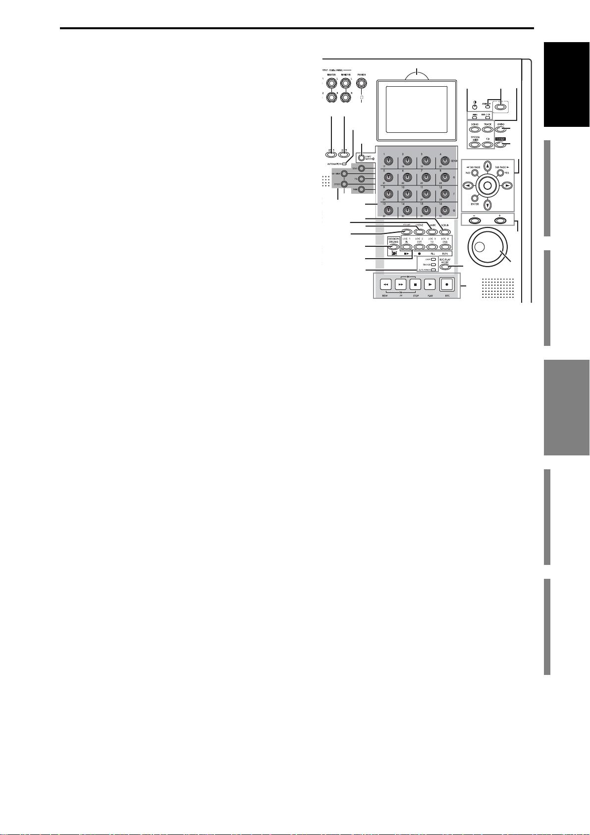
24 METER key
This key accesses a screen that shows the audio levels of the song, the presence or absence of audio
events, and a list of virtual tracks. You can also
switch this to a
“FaderView”
that lets you change
the position at which the level meters ar e inserted, or
check the fader or pan positions.
25 MIXER key
Press this key to access the Mixer page jump menu
screen.
24
25
26
27
39
40
41
42
Introduction
43
44
45
26 AUTOMATION indicator
When this indicator is lit, automation is on; when
automation is being recorded, it will blink.
27 JUMP/MATCH key
The faders and Knob Matrix can be set to behave in a
JUMP or MATCH style when moving a parameter
from its stored value, by changing the Fader/Knob
Control setting (
If this is set to
When the key is lit the
→
p.119) in the Control tab page.
JUMP
, the key will be dark.
MATCH
setting is selected. The key will blink slowly if the position of the
28
31
33
29
30
32
34
35
36
37
38
control knob or fader you’re moving is distant from the stored value. When the knob or fader position approaches the stored value, the blinking will become a rapid flicker, and will change to be
solidly lit when you reach the actual specified value.
By holding down this key while moving a control knob or fader, you can temporarily switch to
JUMP
operation.
28 Direct keys
By pressing these keys you can select the current function of the Knob Matrix, and access the corresponding tab pages.
29 Knob Matrix
These 16 multi-function knobs provide real-time control of the Effects, EQ, Session Drums™, etc.
46
47
for the first time
Before using the D3200
Main featuresParts and their functionItems and functions in the
Parts and their function
30 SCRUB key
Accesses the Scrub page. Use the
value dial
to control the selected function. (→p.40, 146)
31 MARK key
You can register a desired location within a song as a “mark,” and instantly recall that registered
location whenever you want. You can also rename or delete existing marks. (
By holding down this key and pressing the
+
or – keys, you can successively recall the locations
→
p.38, 145)
that were registered at each mark.
32 SCENE key
This key stores mixer settings such as the
channel
faders,
pan
knobs, EQ, and effect sends as a
“scene” at the desired location in a song. If you play back with automation turned on, the stored
scenes will be recalled and changed automatically. You can also edit scenes by rearranging, renaming, or deleting them. (
→
p.50, 105)
33 STORE key
Press this key to register the current time location as a locate point, a mark, or for a scene. (→p.38,
39, 50, 145)
34 SESSION DRUMS key
This key accesses the Session Drums tab page, which you can use to create a drum track for your
song.
LCD screen
Basic operation
9
Page 20

35 LOC 1/IN, LOC 2/OUT, LOC 3/TO, LOC 4/END key
These keys are used to register a specific time location within a song, or to instantly jump to a registered time location.
The time locations registered here can be used as the punch-in/out locations, and to specify the
editing range for track editing operations such as copy or delete. (
You can also assign each key to a specific tab page within the MIXER page, so that pressing the key
will take you to that tab page (
36 LOOP, TRIGGER, AUTO PUNCH indicators
These indicators will light to show which operation - loop record/playback, trigger recording, or
auto punch recording - is selected.
37REC/PLAY MODE keys
Use this key to select the recording mode, or to turn loop playback on/off.
38 Transport keys
Use the
recorder. (
39 DISPLAY UP/DOWN
By pressing this button on the back edge of the display, you can adjust the angle of the LCD screen
over five steps for best visibility.
REC, PLAY, STOP, REW
→
p.149)
Do not use excessive force to move the screen.
→
p.147).
, and FF keys to perform playback or r ecording operations on the
→
p.38, 147)
40 HDD/CD access and MIDI indicators
The HDD/CD indicator will light to indicate that the hard drive is being accessed for recording,
playback or editing, or when the CD-R/RW drive is operating. The MIDI indicator will light when
MIDI messages are received from the
Never subject the D3200 to vibration or impact while this HDD/CD indicator is lit.
41 ON key, standby indicator
Pressing this key will turn the D3200 power on/off. When the standby indicator is lit, pr essing the
ON
key will turn the D3200 on.
When the D3200 is operating, hold down the
42 Page mode keys
Pressing one of these keys will call up the corresponding page mode. When you press the CD key,
the corresponding page menu screen will appear.
43 UNDO key
The Undo function allows you to go back and listen to the audio as it was before an Edit was performed. The Redo function brings back the edited result.
You can retrace your steps through as many as sixteen prior recording or editing operations.
(
→
p.141).
44 TUNER key
Press this key to access the Tuner screen, where you can check the tuning of the audio source that’s
connected to the GUITAR IN jack.
MIDI IN
ON
connector.
key to access the
Power Off
dialog box.
45 Edit controller
Use these controllers to select a button, cell, or tab in the LCD screen, and to edit parameters and
values. The center-click ClickPoint, cursor (
key, and ENTER key let you edit quickly and efficiently.
46 +, – keys
These keys edit the value of the selected parameter as an alternative to using the
keys are convenient when you want to adjust the value in single increments.
10
π†√®
) keys, TAB PAGE /YES key, TAB PAGE /NO
value dial
. These
Page 21
47 Value dial
Use this dial to edit the value of the selected parameter or to change the current time location.
When the Scrub page is displayed, rotating this
dial
will play back the track at the corresponding
speed (up to a maximum of double speed).
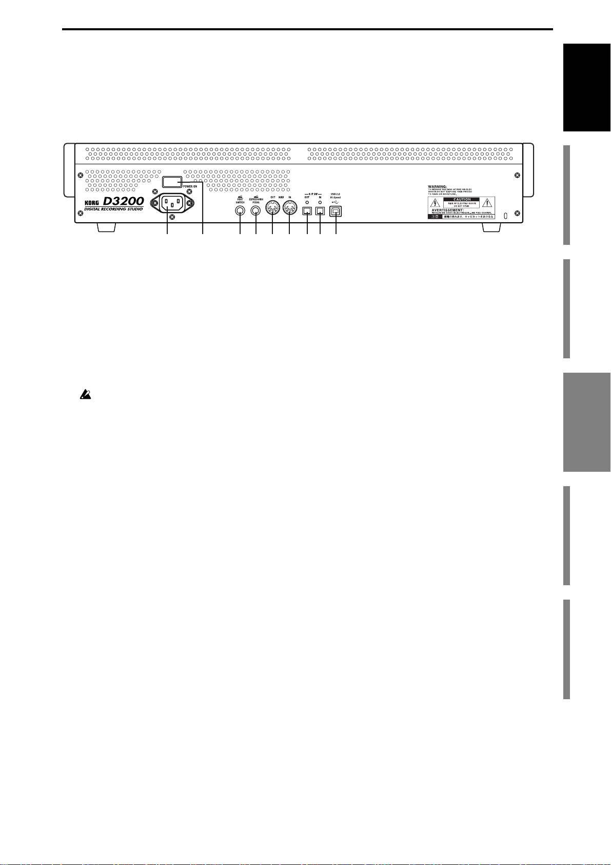
Rear panel
2
1 AC connector
Connect the power supply cable (included) here.
2 Main power switch (POWER ON)
This turns the main power on/off.
When the Main power switch is turned on, the D3200 will be in the standby mode. In the standby
mode, pressing the
to access the
ON
Power Off
key will turn the D3200 on. While the D3200 is operating, hold the ON key
dialog box and select
standby mode. Then you can use the main power switch to turn the power off completely.
To turn off the power, you must first press the ON key to perform the shutdown operation. Never turn off the
Main power switch or disconnect the power cable until shutdown has been completed.
If you turn off the Main power switch or disconnect the power cable before shutdown has been completed, data
and user settings may be lost, and the hard disk may be damaged.
35 7941
6 8
Yes
to shutdown the D3200 and return to the
Introduction
for the first time
Before using the D3200
Main featuresParts and their functionItems and functions in the
3 FOOT SW jack
When your hands are busy playing an instrument, you can use a foot switch to control basic operations of the D3200 recorder.
A foot switch can be used to start/stop the playback, start/end manual punch-in recording, register a mark, or to record tap tempo. (
→
p.26, 63, 66, 119)
Connect a foot switch (optional PS-1) to this jack.
4 EXPRESSION PEDAL jack
You can use a pedal to control a specified parameter of an insert effect. You can control the parameter in real time while you play or record. (
→
p.57, 119)
Connect an expression pedal (separately sold option, EXP-2, XVP-10 etc.) to
this jack.
5 MIDI OUT connector
MIDI messages are transmitted from this connector. Use this when you wish to use the D3200 to
control an external device via MIDI. (
→
p.94, 119)
6 MIDI IN connector
MIDI messages are r eceived at this connector. Use this when you wish to control the D3200 fr om an
external MIDI device. (
→
p.94, 119)
7 S/P DIF OUT jack
This is an optical-type S/P DIF format (IEC60958, EIAJ CP-1201) digital output jack (stereo).
Use an optical cable to connect this jack to the optical digital input of your DAT, MD or other
equipment.
This output provides the same audio as the
MASTER L/R
jacks, but as a digital signal at the same
sampling frequency and bit depth as the current song.
Parts and their function
LCD screen
Basic operation
11
Page 22
8 S/P DIF IN jack
This is an optical-type S/P DIF format (IEC60958, EIAJ CP-1201) digital input jack (stereo).
Use an optical cable to connect this jack to the optical digital output of your DAT, MD or other equipment.
This input provides a digital audio signal at the same sampling frequency and bit depth as the current
song.
9 USB connector
You can use a USB cable to connect the D3200 to your computer.
USB peripheral devices such as external hard disks and CD-R/RW drives cannot be connected to the D3200.
About the CD-R/RW drive
The D3200’s front panel contains a CD-R/RW drive that you can use to backup and restore data, import and export WAV audio files, and to play or write audio CDs.
The disc drive is a precision device; always use it in a horizontal position that is not subject to vibration.
Inserting a disc
Make sure that the D3200 is on.
(1)Press the eject button of the CD-R/RW drive to open the disc tray.
(2)Place the disc accurately in the tray, label side up.
(3)Press the eject button to close the CD-R/RW drive.
Removing a disc
(1) Press the eject button to open the disc tray.
(2)Gently remove the disc from the disc tray.
(3)Press the eject button to close the CD-R/RW drive.
Eject buttonManual eject pinhole
Emergency disc removal
Normally you will be able to remove the disc as described above. However, if this is not possible due
to a power failure or other problem, you can also remove the disc as follows.
Insert a pin-like object of less than 1 mm diameter, such as a straightened paper clip, into the manual
eject pinhole and push. The disc tray will be forced open.
Excessive use of this method may cause the disc drives to malfunction.
This procedure must be performed with the power off.
12
Page 23
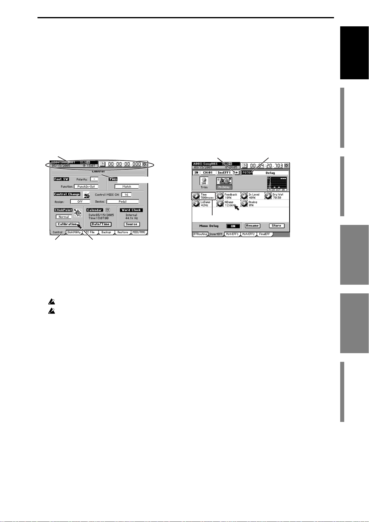
Items and functions in the LCD screen
Use the ClickPoint to move the pointer (p) to a button or icon displayed in the
LCD screen. Then press the center of the ClickPoint to select that button or icon.
In many operations, you can use the pointer (p) to select the item or parameter
to be edited or saved, such as the page, parameter value, or song name.
In this manual, references to the … button, … tab, … cell, or … icon refer to items
shown in the LCD screen. Move the pointer (p) and press the center of the ClickPoint to select the desired item. We’ll use the term “click” to describe this process.
You can also use the cursor keys of the edit controller to move to the item you
want to edit, or use the YES/NO (TAB PAGE) keys instead of the Yes (OK)/No
(Cancel) buttons in the LCD screen, or use the ENTER key to confirm a setting or
operation.
References to “... key,” “... knob,” “... dial,” or “... slider” indicate controls on the
top panel; use the corresponding physical controller to access these items.
a: Song/counter/location/calendar display
b: Page name display
e: Edit cellf: Popup button
Introduction
for the first time
Before using the D3200
Main featuresParts and their functionItems and functions in the
d: Edit icon
Pointerc: Tab
a: Song/counter/location/calendar display
This area displays the currently selected song, the counter (song position),
and the date.
This is displayed in any page mode, and you can modify the counter/calendar setting.
You cannot modify these settings while a dialog box is displayed.
If you haven’t set the date and time, this area is shown in gray.
b: Page name display
This indicates the name of the currently selected page, or editing information.
This item does not appear in certain pages such as the effect pages or “Mixer
View.”
c: Tab
Use the pointer or the
TAB P AGE
keys of the edit controller to select a tab page.
d: Edit icon
When you click an icon such as a fader or knob shown in the LCD screen, a
frame will appear (in most cases) around the icon. This is called the edit icon;
changes you make will apply to the parameter whose icon is enclosed by the
frame.
Parts and their function
LCD screen
LCD screen
Items and functions in the
Basic operation
e: Edit cell
When you click a parameter in the LCD screen, the parameter value will be
highlighted. This is called the edit cell; changes you make will apply to the
highlighted area.
f: Popup button
When you click one of these buttons, a dialog box will appear, displaying
parameters and values for you to select.
13
Page 24
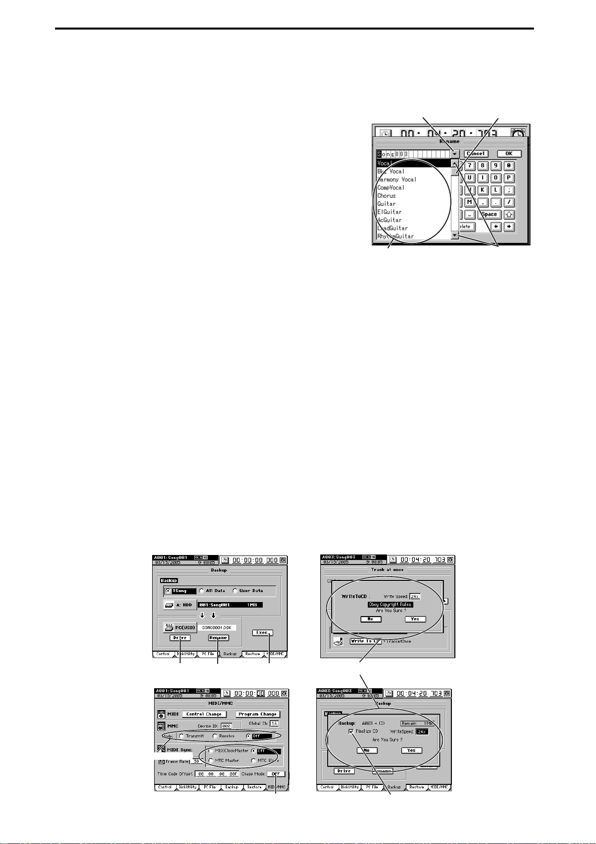
When you’ve finished selecting a parameter or editing a value, press the front
panel YES key or NO key to close the dialog box and return to the previous
tab page. You can also close the dialog box by clicking the Yes (or OK) button
or No (or Cancel) button in the LCD screen.
g: List button
g: List button
When you click this button, a menu list will appear, allowing you to select an item from this list.
h: Scroll bar/scroll buttons
Use these to move up and down through a list of parameter
values that extends beyond the window in the display.
i: Confirmation button
When you click this button, a dialog box will open, asking
whether you are sure you want to execute the settings or
the operation. Some dialog boxes may contain an edit cell
Menu list
for you to specify a value.
Press the front panel YES key or NO key to close the dialog box and return to
the original tab page.
You can also close the dialog box by clicking the Yes (or OK) button or No (or
Cancel) button in the LCD screen.
j: Radio buttons
Use the radio buttons to chose one of the displayed items.
k: Toggle button
This type of button will either change function or toggle between on/off each
time you click it.
h: Scroll bar
h: Scroll buttons
l: Check box
Each time you click one of the check boxes, a check mark will either be added
or removed. Add a check mark if you want to enable that function.
* Other
In addition to the items listed above, the Drive button will open a dialog box
where you can select a drive for editing, and the Rename button will open a
dialog box where you can rename a song or program.
There are also certain screens, such as the routing confirmation screen, that
provide valuable information, but contain no editable items.
Drive button Rename button
i:Confirmation
button
Confirmation dialog box
14
j: Radio buttons
k: Toggle button
l: Check box
Page 25
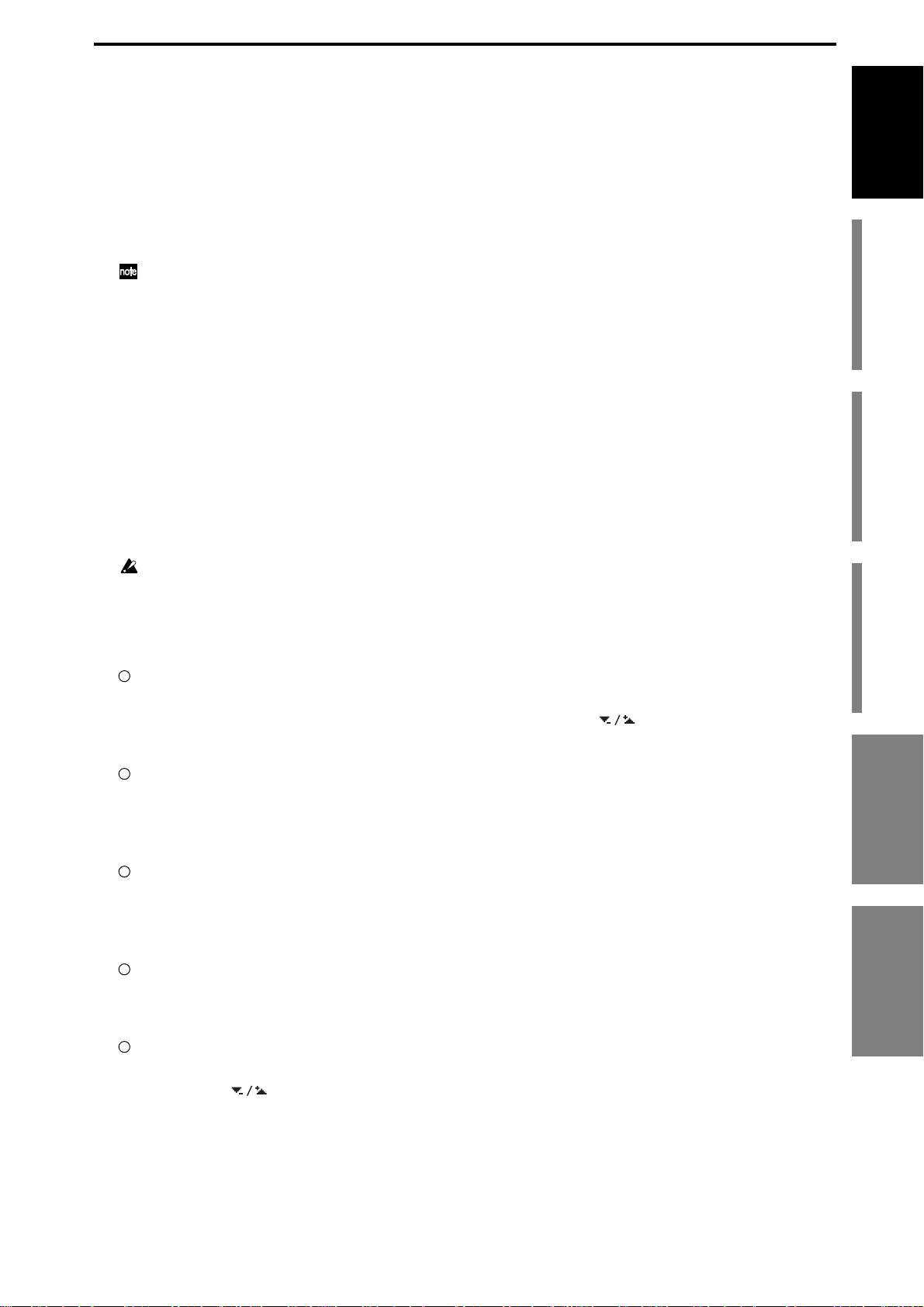
Basic operation
1. Selecting the page mode
If you want to edit a setting or function while watching it in the LCD screen,
you’ll need to press a key to access the page mode that contains that function.
The MIXER key and CD key will display a page jump menu in the LCD
screen; click the page mode buttons shown in the LCD screen to select the
desired mode. Each time you press the MIXER key or CD key , you will r eturn
to this page jump menu.
For details on the functions of each page mode, refer to “Reference” (→p.98–).
2. Selecting a tab page
The numerous parameters contained in each page mode are in turn divided
into tabs. Use the TAB PAGE keys of the edit controller to select a tab page.
You can also move to a tab page by clicking its tab in the LCD screen. Some
pages contain only one tab.
3. Selecting and setting parameters
Selecting a parameter
To select a parameter, click the edit icon, edit cell, or button shown in the LCD
screen.
In most cases, you can use the cursor keys to move between parameters and
press the ENTER key to select one.
You cannot use the cursor keys to move between a dialog box and the original tab page.
Introduction
for the first time
Before using the D3200
Main featuresParts and their functionItems and functions in the
Setting a parameter
There are different methods of setting a parameter, depending on the type of
parameter.
Edit icons, edit cells, buttons
Click the edit icon, edit cell, or button in the LCD screen to highlight it, and
then turn the value dial (or use the +/– keys) to set the value. If buttons
are displayed in the LCD screen, you can click these buttons as well.
Popup buttons, dialog boxes
Click the popup button in the LCD screen to access the dialog box, and then
select the parameter value in the LCD screen. You can also use the value dial
(or +/– keys) to select the parameter value.
Toggle buttons
Toggle buttons in the LCD screen will alternate between on and off each time
you press them. You can also use the cursor keys to highlight the button and
then press the ENTER key to switch the function on and off.
Radio buttons
Click a button in the LCD screen to select it. In addition, you can use the cursor keys to highlight the button and then press the ENTER key to select it.
Selecting one item from a menu list
• Click the desired item from the list shown in the LCD screen to select it.
• Click the buttons in the LCD screen to move the highlighted area.
• Use the value dial or +/– keys to make your selection.
LCD screen
LCD screen
Basic operation
Basic operation Items and functions in the
Fader or pan settings
You can adjust the fader of each channel independently. To adjust the pan,
press the PAN key to access the “FADER PAN” tab page, and use the Knob
Matrix.
15
Page 26

Send and equalizer
When you’re in a tab page where you can edit parameters, or if you’ve
pressed the SEND key or EQ key to access the tab page, you can use the
Knob Matrix to edit the parameters or values.
Editing effects
When the effect parameter knobs are shown in the LCD screen, or if you’ve
pressed the EFFECT key to access the tab page, you can use the Knob Matrix
to select parameters or edit their value.
Selecting a channel
If the CH SELECT key is lit, you can press the channel key of the desired
channel to directly select it for editing.
Switching between channels 1–16 and 17–32
In the case of parameters for which the LCD screen cannot display all 32 channels at once, sixteen channels will be displayed at a time, depending on
whether the 1–16 key or 17–32 key is lit.
4. Panel key combination shortcuts
By pressing two of the panel keys simultaneously, you can use various shortcuts such as moving between pages, switching functions, or changing the
location.
Some examples of shortcuts
• Hold down the SONG key and press the + key or – key to increment/
decrement the song number.
• Hold down the MIXER key and press the LOC 1, 2, 3, or 4 key to recall
the memory page.
• Hold down the MIXER key and press the π key or √ key to increment
the MIXER page.
• Hold down the MIXER key and press the † key or ® key to decrement
the MIXER page.
• Hold down the π key and press the SYSTEM/MIDI key to display the
calendar dialog box.
• Hold down the π key and press the SESSION DRUMS key to switch
the TimeDispType.
• Hold down the SYSTEM/MIDI key and press the ENTER key to enter
USB mode.
There are many other shortcuts in addition to those listed above. Refer to the
list of shortcuts (→p.178).
16
Page 27
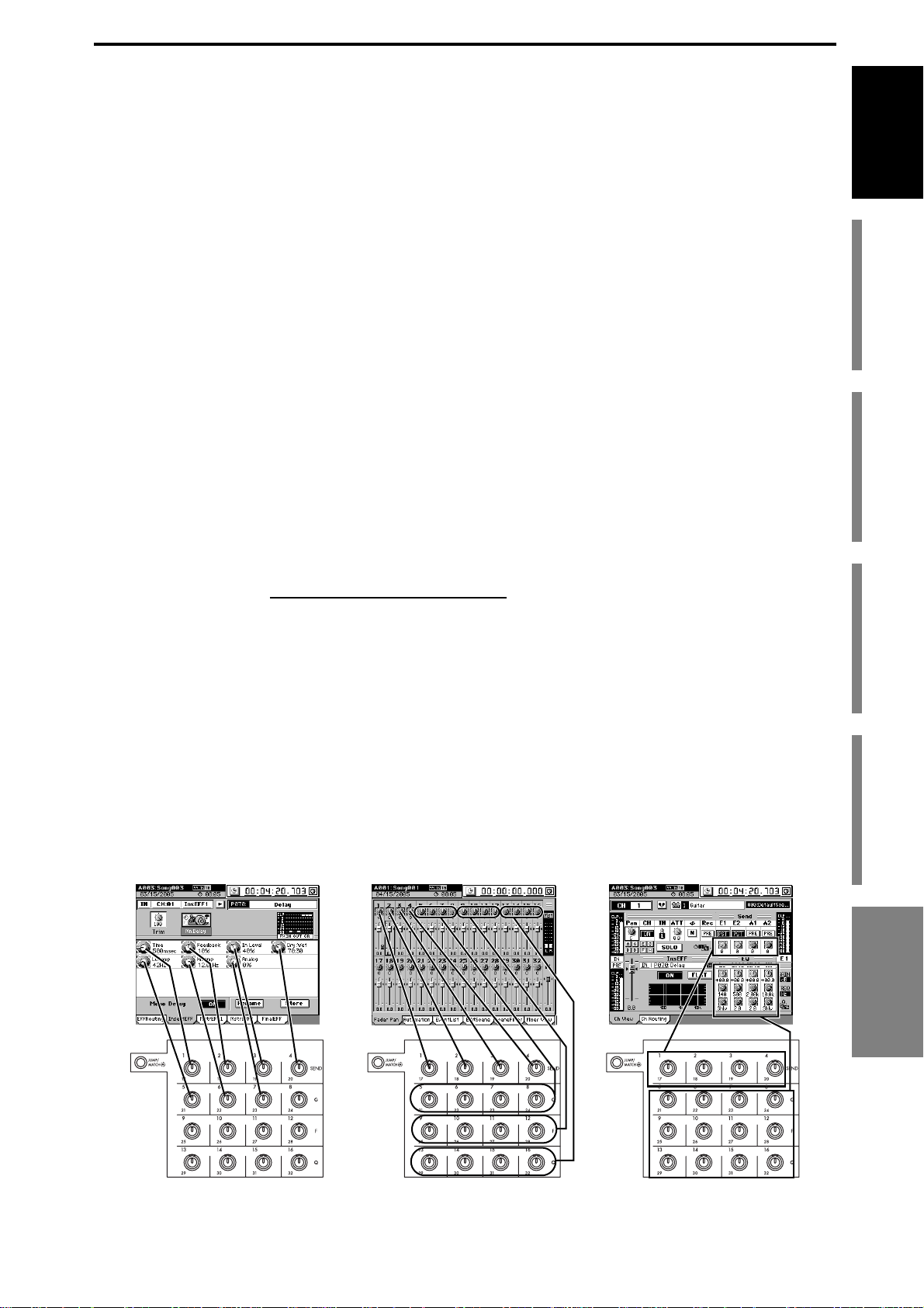
Examples of operation
You can use the sixteen control knobs of the Knob Matrix in the following tab pages. In pages where there are seventeen or more knob icons, you can hold down
the JUMP key and use the cursor keys to switch between groups of sixteen knobs
for editing.
CH VIEW page Ch View tab page
EFFECT page InsertEFF, MstrEFF1, MstrEFF2, and FinalEFF tab pages
SEND page EFFSend1, EFFSend2, Aux1Send, and Aux2Send tab
pages
EQ page EQ/ATT and MasterEQ tab pages
FADER page Fader Pan and Mixer View tab pages
SOLO page CueLevel tab page
CH INPUT page SubMix1-4, SubMix5-8, and SubMix9-12 tab pages
DRUMKIT screen
METER screen (when FaderView is selected)
Figure 1 shows the EFFECT, “MstrEFF1” tab page.
To select this tab page, press the top panel EFFECT key, and then click the
“MstrEFF1” tab in the LCD screen.
In this screen, the knob icons are linked with the Knob Matrix below; you can
move a knob to edit the value directly. Knobs for which no knob icon is shown
have no effect.
Introduction
for the first time
Before using the D3200
Main featuresParts and their functionItems and functions in the
Figure 2 is the MIXER, FADER/PAN/AUTOMATION
“Fader Pan” tab page. To
select this tab page, press the direct key PAN. Alternatively, you can press the
MIXER key and then click the screen.
In this screen, moving the fader or Knob Matrix (corresponding to pan for each
channel) of the desired channel will automatically select that channel, and change
its fader or pan value.
Figure 3 is the CH VIEW, “Ch View” tab page.
To select this tab page, press the direct key CH VIEW.
You can also click the screen to select this tab page after pressing the CH VIEW
key.
In this screen, the fader, EQ, and Send are controlled directly by the fader of that
channel and by the Knob Matrix.
Figure 1 Figure 3Figure 2
LCD screen
Basic operation
Basic operation
17
Page 28
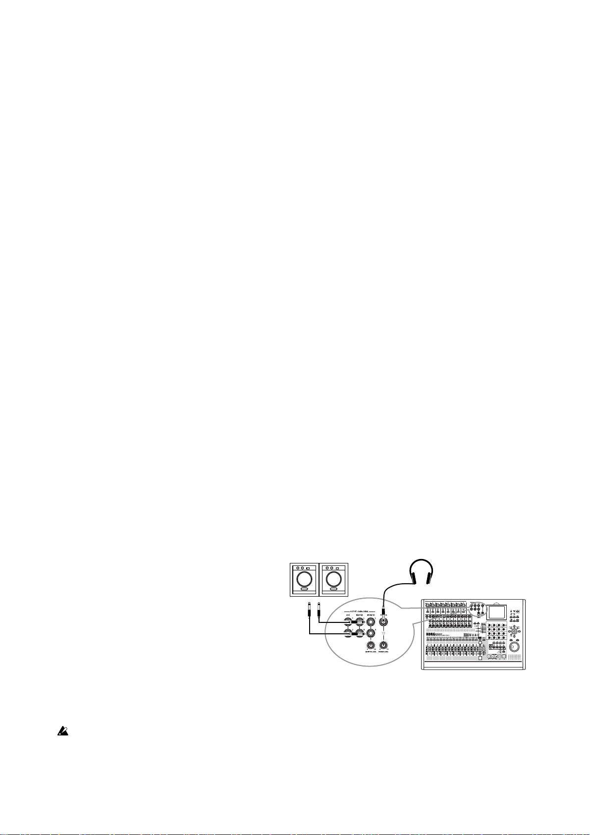
Quick Start
This Quick Start is designed to provide a few examples of some common tasks,
while helping you get familiar with the operations of the D3200.
Step 1: Preparations
The first step explains how to connect your monitor speakers or headphones,
how to turn the D3200 on, and how to listen to the demo songs.
Step 2: Quick recording
This step will cover how to connect a guitar, keyboard, or mic to the D3200,
how to record your performance on to a track, and how to play back the
recording and listen to the results.
Step 3: Overdubbing
Overdubbing allows you to record additional tracks as you play along with
the performance you recorded in step 2.
Step 4: Mixdown and mastering
In this step you can apply effects and EQ to each track to adjust the overall
balance.
Finally, you can apply effects and EQ to the entire song to add overall compression and tonal adjustments, and mix your song down to the stereo master
track.
Step 1: Preparations
1. Connections
Please note the following items before you begin.
The D3200 automatically stores the date and time each time a song is saved, so
that you can tell when a song was updated. Before you begin, we recommend that
you set the date and time (→p.2 “Setting the calendar”).
If you’re not sure how to use the buttons or icons that appear in the LCD screen,
refer to “Items and functions in the LCD screen” (→p.13).
Connections
(1)Connect the MONITOR L/R jacks to your
monitor speaker system, or connect a set
of headphones to the PHONES jack.
(2)Set the MONITOR LEVEL knob to –∞. If
you are using headphones, set the headphone PHONES LEVEL knob 1 all the
way to the left.
2. Turn the D3200 on
Monitor speaker etc.
(1)
(1)
(2)
Headphones
Connect the AC power cable (included), and turn on the power.
Be sure to use the procedure described in “● Power-on” (→p.1).
Use an independent AC outlet whenever possible. If a circuit breaker should trip for some reason, any unsaved data will be lost and the internal hard drive or CD-R/RW may be damaged.
18
Page 29
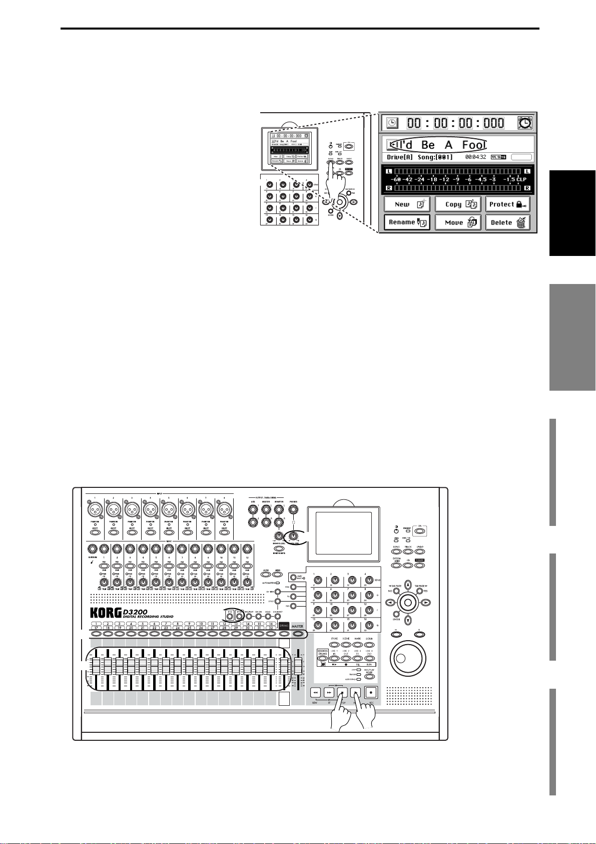
3. Listen to the demo song
When it ships from the factory, the D3200 contains pre-recorded demo songs.
This section explains how to listen to one of the demo songs.
(1)Press the SONG key.
(2)Make sure that the demo song is
shown in the upper part of the
screen.
(3)Set all the channels to play mode.
Press the REC/PLAY key, and check
that the track 1 through 16 channel
keys are set to Play (lit green). Press
the 17–32 key and make sure that
the track 17 through 32 channel keys
are also set to Play (lit green).
If any key is set to Record (lit red), press that key to change the status to Play
(lit green).
If the key located above the master fader is lit, press it several times to make it
go dark.
(4)Press the PLAY key to start playing the demo song.
(5)Adjust the Monitor Level.
Slowly turn the MONITOR LEVEL knob toward the right to adjust the playback volume. If you have connected headphones, turn both the MONITOR
LEVEL knob and the PHONES LEVEL knob slowly toward the right to
adjust the volume.
(1)
(2)
Quick Start
Step 1: PreparationsStep 2: Quick recordingStep 3: OverdubbingStep 4: Mixdown and
Step 1: Preparations
(6)Adjust the “mix.”
While the song plays, operate the channel faders and notice how the balance
between the tracks changes.
(7)When the demo song ends, press the STOP key.
Hold down the STOP key and press the REW key to return to the beginning
of the song (→p.37 “2. Location”).
(5)
(3)
(3)
(6)
(7)
(4)
mastering
19
Page 30
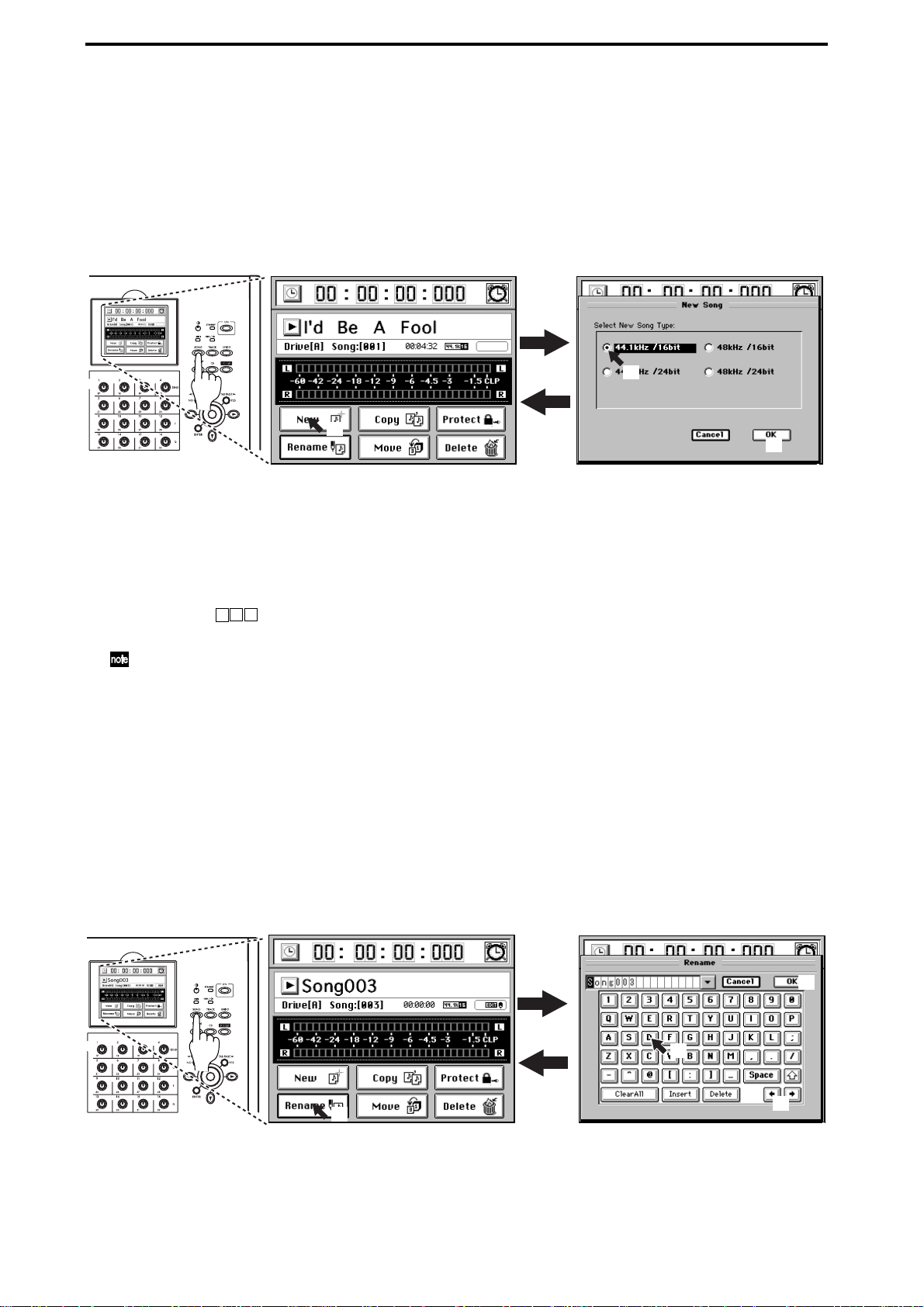
Step 2: Quick recording
1. Create a new song
In order to begin recording, you must first create a new song.
(1)Press the SONG key to access the SONG page.
(2)Click the New button. The New Song dialog box will appear.
(1)
(2)
In the “Select New Song Type” area, select the desired sampling frequency
and bit depth for the song that you want to create.
For this example, click 44.1 kHz/16 bit.
(2)
(3)
(3)Create the song.
Click the OK button in the screen (or press the panel YES key). A new song
named “Song ”* will be created following the last existing song.
The newly created song will be selected, and will appear in the SONG page.
You can change the location (song drive) in which the song is created (→p.36 “Selecting a
song from another song drive”).
2. Name the song
Here’s how to rename the newly created song.
Before you start recording, we recommend that you give your song a name that
will help you recognize the content of the song.
(1)Press the SONG key to access the SONG page.
Here you can edit the name of the song that’s displayed. If you want to select
a different song, refer to “1-3. Selecting a song” (→p.36).
(2)Click the Rename button to display the Rename dialog box.
(4)
(3)Edit the song name.
When you press a character or numeral button, the highlighted character in
the song name will change.
20
(1)
(2)
(3)
(3)
Page 31

The highlighted area will then move one step toward the right. Repeat this
step to edit the song name.
If you want to edit only a portion of the song name, click the buttons to
move the highlighted area, and then click a character or numeral button.
Use the buttons in the LCD screen to perform the following operations.
“0...9”: Input a numeral (e.g., “0”)
“A...@_...”: Input an alphabetical character (e.g., “A”) or symbol (e.g., @, _).
: Input a space.
: Switch the alphabet buttons between lower case and upper case.
: Insert a space, and move the subsequent characters backward.
: Delete the character at the cursor location.
: Erase the entire name.
(4)Confirm the changes.
When you have finished naming your song, click the OK button in the LCD
screen (or press the panel YES key).
If you decide to discard the change you made, click the Cancel button in the
LCD screen (or press the panel NO key).
3. Connect your audio sources to the mixer inputs
Quick Start
The mixer can accept twelve channels of analog inputs, two channels (one stereo pair) of digital (S/P
DIF) input (→p.44 “1-2. Digital input”), and a stereo
Mic
(2)
OUTPUT
input from the internal Session Drums (→p.59 “Recording patterns on a track”). Here we'll explain
how to connect analog audio sources to channels 1-4.
Connect mics and instruments to the INPUT jacks
Guitar
Microphones, guitars & basses, and keyboard/synthesizer instruments all have different output levels
(1)
and require different input connections. Here, we’ll
give an example of each type.
(1)Connect a guitar to the guitar input.
Rotate the INPUT 1 TRIM knob all the way to the
Connection example
left, and connect your guitar to the GUIT AR IN jack.
The GUITAR IN jack is shared with INPUT 1, and
Guitar
Mic
the two cannot be used simultaneously. (→p.7 “3
GUITAR IN jack”)
(2)Connect a microphone to one of the analog inputs.
Rotate the INPUT 2 TRIM knob all the way to the
left, and connect a mic to one of the INPUT 2 jacks.
Microphones will generally connect to the XLR
INPUT1
INPUT2
INPUT4
INPUT3
inputs, although some will have plugs that can connect to the TRS balanced phone jacks. Additionally,
some microphones require phantom power fr om the
mixer. Each of the D3200’s XLR inputs are equipped
CH1 CH2 CH3 CH4
with switchable phantom power supplies. Be sure
and choose the right connection for your microphone. And never connect or disconnect a microphone while the phantom power is on.
(3)Connect the stereo outputs from a keyboard to a
pair of TRS phone jack inputs.
1Tr
2Tr
Rotate the INPUT 3 and 4 TRIM knobs all the way to the left, and connect the
outputs of your keyboard to the INPUT 3 and 4 phone jacks.
(3)
L R
INPUT5
Recorder
3Tr 4Tr
Keyboard
Keyboard
INPUT11
S/P DIF L, R
INPUT12
CH
32Tr
Step 1: PreparationsStep 2: Quick recordingStep 3: OverdubbingStep 4: Mixdown and
Step 2: Quick recording
32
mastering
21
Page 32

Assign the inputs to channels
Each of the inputs needs to be assigned to a channel. First, let’s assign the guitar input to channel 1.
(1)Call up the input assignment page.
Press the MIXER key, and then click the page jump menu CH INPUT/SubMixer
access the “Ch Assign” tab page.
(2)Select a channel.
In the tab page, click the CH1 SOURCE channel icon. The icon will be enclosed by a frame.
(3)Select an input.
Click the buttons to assign “1” (INPUT 1) as the input source for channel 1 (CH1
SOURCE).
You can also use the value dial or the +/– keys to change this setting.
button to
(1)
(1)
(1)
(2)
Adjust the CH 1 input level to verify that the sound of the
guitar has been assigned.
(4)Set the fader levels.
Lower the CH1 fader to “–∞”, and raise the MASTER
fader to the “0” position.
(5)Using the input PADs.
(5)
(7)
The pad lowers the input signal by an additional 26dB.
For a mic or guitar , leave the PAD key unpressed when
making your settings. For a line-level output, such as
from a keyboard, press the PAD key to the in position
(on) when making your settings.
(6)
(6)
(6)Arm channel 1 so you can monitor the input.
Turn on the REC/PLAY key, and press the CH1 channel key to select Record (key lit red).
(4)
(8)
(7)Set the trim level.
As you play your guitar, the INPUT 1 peak indicator (the LED at the upper left of TRIM) will
light. Adjust the TRIM knob so that your loudest playing does not cause the LED to light red.
(3)
(4)
22
(8)Set the fader level for monitoring.
Gradually raise the CH1 fader while playing your guitar, and you will hear sound from your
monitor speakers.
If you are using headphones, adjust both the PHONES LEVEL knob and the MONITOR
LEVEL knob.
Using these same methods, we can assign the mic and keyboard
inputs to their own channels.
(9)Assign input 2 to channel 2.
Click the CH2 SOURCE channel icon, and assign “2” (INPUT
2) as the input source for channel 2 (CH2 SOURCE).
Using this setting, the sound of the mic connected to INPUT
2 will be sent to CH2. Set and check the mic level as described
in steps (4)–(8).
(10)Assign input 3 to channel 3.
Click the CH3 SOURCE channel icon, and assign “3” (INPUT 3) as the input source for channel
3 (CH3 SOURCE). Repeat this step and assign “4” (INPUT 4) as the input source for channel 4
(CH4 SOURCE).
Page 33

Using these settings, the keyboard connected to INPUT 3 and 4 will be assigned to CH 3 and 4.
Set the pan knob of channel 3 all the way to the left; set the pan knob of channel 4 all the way to
the right. Now you can monitor your keyboard in stereo.
Check the keyboard sound and set the level as described in steps (4)–(8).
4. Adding EQ and EFFECTS
If you want to record without any further processing, proceed to “5. Recording.” If you want to use
each inputs’s 4-band parametric EQ and/or apply the D3200’s internal effects as you record, read
the following sections: “Applying EQ to the input sound” and “Applying effects to the input
sound.”
Applying EQ to the input sound
On the D3200 it’s also easy to apply EQ after recording.
Channels 1–23 are equipped with a four-band parametric EQ to shape the tonal characteristics of
the sound. Channels 24–32 feature a two-band shelving EQ. In the next example, you can apply EQ
to your guitar.
(1)Press the EQ key to access the “EQ/ATT” tab page.
(2)Choose a channel.
Click the CH cell, and use the value dial or the panel + or – keys to select channel 1, the channel
assigned to your guitar input.
Alternatively, you can press the CH SELECT key and turn on a channel key to select the channel.
Quick Start
EQ window
(2)
(3)
(1)
(3)Use the Knob Matrix to adjust the EQ.
As you play, use the Knob Matrix to adjust the gain, center frequency, and Q values for each of
the EQ bands.
The resulting EQ curve will be displayed in the EQ window.
If the level meter clips, press the ATT knob icon in the LCD screen and adjust it to a value that does not cause clipping. Keep in mind that if you are boosting the gain in multiple bands, you are increasing the level of the signal
overall, and you will need to use the ATT knob to control the level. Instead of increasing the gain in multiple bands,
you might try decreasing certain bands, but keeping the difference in gain between the bands the same. This will
keep the level more consistent and avoid distortion.
You can apply EQ to the mic and keyboard inputs as using the same method.
Step 1: PreparationsStep 2: Quick recordingStep 3: OverdubbingStep 4: Mixdown and
Step 2: Quick recording
(4)Adjust the EQ settings of channel 2.
Click the CH cell and use the value dial or the panel + or – keys to select the channel assigned to
your microphone input 2 (channel 2).
Now you can apply EQ to the mic connected to INPUT 2. Adjust the EQ as described in step (3).
(5)Adjust the EQ settings of channel 3.
Click the CH cell and use the value dial or the panel + or – keys to select the first channel
assigned to your keyboard. In this example, input 3 (channel 3).
Now you can apply EQ to one channel of the stereo keyboard connected to INPUT 3. Adjust the
EQ as described in step (3).
mastering
23
Page 34

(6)Adjust the EQ settings of channel 4.
Click the CH cell and use the value dial or the panel + or – keys to select the other channel
assigned to your keyboard. In this example, input 4 (channel 4).
You can apply EQ to the other channel of the stereo keyboard connected to INPUT 3. Adjust the
EQ as described in step (3).
The D3200 allows you to “pair” adjacent pairs of channels (odd, even). If you pair the two keyboard
channels, the EQ settings you make for one channel will also be applied to the other channel as well,
so you do not need to EQ each channel separately. (→p.46 “3-5. Pairing”).
Applying effects to the input sound
It’s also easy to apply the D3200’s effects after recording the sound (→p.28).
Here’s how to apply effects to the input from your guitar. First, let’s assign insert effect 1 to
channel1; the guitar’s input channel.
(1)Press the EFFECT key and select the “EFFRouting” tab page.
(2)Assign the effect routing.
Click the InsEFF1 IN/TR cell (it will become highlighted) and use the value dial or the +/– keys
to select “IN.”
IN stands for Input, and TR stands for Track; choose IN if you want to apply the effect to the
input sound, or TR if you want to apply the effect to the playback.
(3)Select a channel.
Click the InsEFF1 CH cell (highlighted) and use the value dial or the +/– keys to select “1.”
Insert Effect 1 is now assigned to the guitar’s input channel. Next, let’s choose an effect.
(4)Choose an effect type.
Select the InsEFF1 edit cell (highlighted), click the Select button. The Select EFF Category dialog
box will appear. Here you can select what type of effect you want to use on the guitar.
For this example, click “Dynamics&Filter” from the “Mono” category.
(2) (3)
(1)
(1)
(4)
(4)
(4)
(5)Choose an effect program.
The Select EFF Program dialog box will appear . Now you can
select the effect.
For this example, click “Compressor” and then click the OK
button in the LCD screen (or press the panel YES key).
Insert effect 1 is now applying a “Compressor” to the guitar
(5)
sound assigned to channel 1.
You can apply effects to the mic and keyboard inputs in the same
way. Here are a couple more examples.
(6)Assign insert effect 2.
Set InsEFF2 to IN, and set the CH to 2.
Click the InsEFF2 edit cell and select the “Room” effect from “Reverb&Delay” in the “Mono”
category.
24
(5)
Page 35

(7)Assign insert effect 3.
Set InsEFF3 to IN and CH to 3, and set InsEFF4 to IN and CH
to 4.
In the InsEFF3 edit cell, select the “Rotary Speaker” effect
from “SFX&etc” in the “Stereo” category.
Because this is a stereo effect, the same effect will automatically be selected for InsEFF4. (→p.54 “Effects”)
For details on editing the parameters of the effects you selected,
refer to “4. Editing the effects” (→p.56).
5. Recording
Now you’re ready to record. In this example, let’s record the guitar.
Preparations for recording
(1)Setting the recording mode
Press the REC/PLAY MODE key. In the “RecMode” tab page, click the radio button to select
“Normal.”
(2)Select the recording status.
On the D3200, the recording signal of each channel can be sent from either Before (PRE) the
fader, or after the fader (PST). Press the SEND key, and in the “RecSend” tab page, make sure
that the channel you’re recording is set to PRE. If it is set to PST, click the button to change the
setting to PRE.
(1)
(1)
Quick Start
Step 1: PreparationsStep 2: Quick recordingStep 3: OverdubbingStep 4: Mixdown and
Step 2: Quick recording
(3)Set a meter view.
Press the METER key.
Click the popup button in the screen to display the Meter/Track Type dialog box.
(3)
(3)
(3)
(3)
Using the radio buttons, select “PreFader” as the Meter Position, and “TrackView” as the view.
Then click the OK button (or press the panel YES key).
(3)
mastering
25
Page 36

Start recording
The location currently shown in the counter is where the recording will begin.
(→p.37 “2. Location”)
(1)Set the D3200 to record-ready.
Press the REC key (the key will blink).
(2)Press the PLAY key.
The D3200 will begin recording, both the REC and PLAY keys will
light.
(3)Begin playing your instrument.
(4)When you have finished playing, press the STOP key to stop recording (the
keys will go dark).
The track view will display a bold line to indicate the region where recording took
place. This line indicates the event data. Event data is displayed even for recorded
areas where you did not actually play your instrument.
6. Playback
(1)Set channel 1 to play.
Turn the REC/PLAY key on. Then press the channel key of track 1 (the track
you just recorded) to set it to Play (key lit green).
(4) (2) (1)
(2)Return to the beginning of the song.
Hold down the STOP key and press the REW key to return to the beginning
of the song (→p.37 “2. Location”).
(1)
(1)
(2)
(2)(4) (3)
(3)Press the PLAY key to begin playback (the key will light).
•You can apply EQ to the playback audio (→p.46 “Applying EQ to the playback”).
•You can adjust the level and pan of the playback audio (→p.45 “3-1. Adjusting the volume,” →p.45 “3-2. Adjusting the pan”).
•You can apply effects to the playback audio (→p.54 “Effects”).
•You can play internal rhythms along with the playback (→p.58 “Session
Drums™”).
(4)Press the STOP key to stop the playback (the PLAY key goes dark).
Even if there is no event data, playback will not stop until you press the STOP key.
26
Page 37

Step 3: Overdubbing
Overdubbing allows you to layer multiple performances. This way, you can
record additional tracks, as you listen to the previously recorded tracks play back.
In this example, record your mic or keyboard on a new track while listening to the
guitar performance that you recorded in the preceding steps.
1. Recording
First, let’s arm track 2 to record, and set track 1 to play
back.
Preparations for recording
(1)Arm track 2 for recording.
Turn the REC/PLAY key on.
Press the channel key of track 2, and set it to
record; REC (key lit red).
(2)Set Channel 1 to play.
Press the channel key of track 1 and set it to play
back; PLAY (key lit green).
(3)Return to the beginning of the song.
Hold down the STOP key and press the REW key
to return to the beginning of the song (→p.37 “2.
Location”).
Start recording
(1)Set the D3200 to record-ready.
Press the REC key (the key will blink).
(2)Press the PLAY key.
recording will begin (REC and PLAY keys will light).
Connection example
Guitar
INPUT1
Play Rec
Already
recorded
Mic
L R
INPUT3
2Tr
INPUT4
INPUT5
Rec
Recorder
3Tr
INPUT2
CH1 CH2 CH3 CH4
1Tr
4Tr
Keyboard
S/P DIF L, R
Rec
Drums L, R
CH
32
32Tr
Quick Start
Step 1: PreparationsStep 2: Quick recordingStep 3: OverdubbingStep 4: Mixdown and
(3)While listening to the playback, record an additional part.
(4)When you have finished performing, press the STOP key to stop recording
(the key will go dark).
2. Playback
Play back the song to verify that your performance was recorded correctly.
(1)Follow steps (1)–(4) of “6. Playback” in the previous section “Step 2: Quick
recording.”
Step 3: Overdubbing Step 2: Quick recording
27
mastering
Page 38

Step 4: Mixdown and mastering
“Mixdown” refers to the process of mixing all the individual
tracks together to create a stereo mix of your song. In addition
to adjusting the pan and level of each track’s playback, during
mixdown you can also apply insert effects to individual
1Tr
CH1 CH2 CH3 CH4
2Tr
Recorder
3Tr
tracks, add master effects, and adjust the EQ settings of the recorded tracks.
After you’ve mixed-down your song, the next step is to use
the master EQ and the final effect to enhance the overall tone
Pan
Pan
Pan
and dynamic character of your song to create a finished master; this process is called “mastering.”
On the D3200, you can perform mixing and mastering at the
same time.
1. Applying effects and EQ to individual channels
Applying effects to individual channels/tracks (Insert Effect)
You can apply an effect to the playback of an individual track by assigning an insert effect to that mixer channel.
(1)Press the EFFECT key to access the “EFFRouting” tab page.
(2)Assign effect routing to the playback.
Click the IN/TR cell (it will become highlighted), and use the value dial or the
panel + or – keys to select “TR.”
Perform the actions described beginning with step (3) under “Applying EQ to
the input sound” (→p.23).
4Tr
CH
Pan Pan
Master
Master
Recorder
Tra ck
32Tr
32
(2)
(1)
(2)
Applying EQ to each channel/track
(1)Press the EQ key to access the “EQ/ATT” tab page.
Alternatively, you can access the “EQ/ATT” tab page by clicking the EQ/ATT/PHASE
button of the page jump menu.
(2)
(4)
(3)
(1)
(4)
(4)
(1)
28
(4)
Page 39

(2)Select a track for EQ.
Click the CH cell, and use the value dial or the panel + or – keys and select
one of your recorded tracks that needs more EQ.
Alternatively, you can press the CH SELECT key and press a channel key to
select the channel to which you want to apply EQ.
(3)Set the meters to monitor the input and prefader levels (IN/PRE).
Click the position cell and set it to read IN/PRE. These settings allow you to
simultaneously check the input signal level, and the level of the signal immediately after the EQ has been applied.
(4)While listening to the playback, use the Knob Matrix to adjust the EQ.
If the track you want to EQ is not playing back, turn the REC/PLAY key on, be
sure the channel key for that track is set to Play (key lit green).
If the level meter (PRE) clips, click the ATT knob icon in the LCD screen and adjust it to a
value that does not cause clipping.
Adjusting the pan
Adjust the stereo position of the playback tracks.
Press the PLAY key, press the PAN key, and use the Knob Matrix to adjust the
stereo position of each track.
Quick Start
Using the channel/track sends to apply effects (Master Effects)
The D3200 contains two master effects that can be
From the EQ
output of
each ch.
used to apply spatial effects such as reverb.
You can control how much signal from each channel
is being sent to each of the master effects. In addition
to individual sends, the overall effects balance is also
controlled by the effect return level.
Selecting a master effect
(1)Press the EFFECT key to access the “MstrEFF1” tab page.
(2)
(1)
(1)
Pre-fader
Post-fader
Send
Send
Master bus
Pan
Master
Effect 1
Master
Effect 2
Step 1: PreparationsStep 2: Quick recordingStep 3: OverdubbingStep 4: Mixdown and
(3)
(2)Select an effect type.
Click the popup button beside the effect name, and the
Select EFF Category dialog box will appear.
(3)Select an effect program.
Click a category button in the LCD screen, and the Select
EFF Program dialog box will appear.
For this example press “Club” and then click the OK button. If you want to go back and look in another category,
click Cancel button.
(3)
(3)
mastering
mastering
Step 4: Mixdown and
29
Page 40

Adjusting the Master Effect 1 Send amount for each track
(1)Press the SEND key to access the “EFF1Send” tab page.
(2)Set the master effect 1 sends to pre-fader.
You can choose to send either the pre-fader signal (PRE) or the post-fader signal (PST) to master effect 1.
From the EQ output of
each channel/track
Pre-fader
Pan
Post-fader
Send
Master
Effect 1
Master bus
Click the PRE (PST) button beside the knob icon to make your choice. For this
example, select “PRE” for all tracks that will be using master effect 1.
(3)Adjust the send amount of each track.
Using the Knob Matrix adjust the send value for your recorded tracks.
(3)
(1)
(2)
(1)
Set the send value to “0” for any tracks that you don’t want to use master
effect 1.
(4)Make settings for master effect 2 in the same way, using the “MstrEFF2”
and “EFFSend2” tab pages.
Checking and adjusting the master effect
(1)Play back the song.
As the song plays, listen to the output of the master bus to hear the results of
your effect settings.
(2)Adjust the return form the master effects.
Press the EFFECT key and the“MstrEFF1” (or “MstrEFF2”) tab page. Adjust
the return level and return balance from the master effect to the master bus.
For this example, set “Return Level” to “100,” and “Return Balance” to “C.”
(3)If the output level meter is clipping, click the TRIM knob icon in the LCD
screen, and use value dial or the + or – keys to adjust the trim so that clipping does not occur.
For details on editing the parameters of the selected effect, refer to “4. Editing
the effects” (→p.56) in the Operation section.
30
Page 41

2. Applying Final (or mastering) effects and EQ to the entire song
Set the meters to display the post fader levels.
Press the METER key.
Click the popup button to open the “Meter/Track Type” dialog box.
Using the radio buttons, set the Meter Position to “Post Fader,” and set Select
View to “Track View.” Now the meters will show the level for each fader.
Applying an effect to the master bus (Final Effect)
(1)Press the EFFECT key and select the “FinalEFF” tab page.
(2)Choose an effect category.
Click the popup button to open the Select EFF Category window, and select a
final effect category.
For this example select “Reverb&Delay.”
(2)
Quick Start
(2)
(1)
(1)
(3)Choose a final effect.
For this example click “Smooth Hall” and then click the OK
button (or press the panel YES key).
(4)Play back the song.
Press the PLAY key and listen to the output of the master
bus or the headphones to hear the results of the final effect.
(5)Make the desired adjustments, and then press the STOP
key.
For details on editing the parameters of the effect that you
selected, refer to “4. Editing the effects” (→p.56) in the Operation section.
Step 1: PreparationsStep 2: Quick recordingStep 3: OverdubbingStep 4: Mixdown and
(3)
(3)
mastering
mastering
Step 4: Mixdown and
31
Page 42

Applying EQ to the master bus (Master EQ)
(1)Press the EQ key to access the “MasterEQ” tab page.
(2)Link the channels to share settings.
For this example, click the Link button to turn it on (highlighted).
When the Link button is on, adjusting either side (left or right channel) will
make the same settings for both channels (→p.46).
(3)Make sure that the L button is on (highlighted); the display will show the
left channel master EQ screen.
(4)Press the PLAY key.
(5)Adjust the master EQ as the song plays.
While listening to the output of the master bus or headphones, adjust the
master EQ parameters using the Knob Matrix.
The EQ window displays the EQ curve. You can switch the master EQ on/off
by clicking the ON/OFF button in the LCD screen.
If you want to make independent settings for the left and right master EQ, turn off the Link
button and use the R or L button to select right or left.
(6)When you‘re done adjusting the master EQ, press the STOP key.
EQ window
(1)
(6) (4)
(5)
(3)
(2)
(5)
(1)
32
Page 43

3. Recording the master track
To create an audio CD, you need to create a stereo master track.
There are eight virtual master tracks (per song). This way, you can create various
mixes of your song, and compare them before choosing your favorite.
(1)Specify a virtual track.
Press the TRACK key, select the “MasterTrk” tab page, and click the V-Level
buttons to select a virtual master track (A–H).
(2)Arm the master track for recording.
Press the MASTER key located above the MASTER fader to select Record
mode (key lit red). The REC/PLAY key will automatically be turned on, and
the channel keys of each track will automatically be set to Play mode (key lit
green).
(3)Adjust the recording level.
• Set the MASTER fader to “0.”
•Press the METER key.
•Press the PLAY key to play back the song.
• While watching the master bus level meter, adjust the MASTER fader so
that clipping does not occur.
Quick Start
(1)
(3)
(2)
(5)(6)(5)(6) (5)
(1)
(1)
(3)
(4)
(4)Return to the beginning of the song. (→p.38)
(5)Record the master track.
Press the REC key to enter record-ready condition (LED blinking), and then
press the PLAY key to begin recording (LED lit).
When you finish recording, press the STOP key.
Step 1: PreparationsStep 2: Quick recordingStep 3: OverdubbingStep 4: Mixdown and
(6)Listen to the recorded result.
Press the MASTER key located above the master track to set it to play (key lit
green).
The channel keys of tracks 1–16 will automatically change to muted (key
unlit).
Return to the beginning of the song. (→p.38)
Press the PLAY key and enjoy your song.
mastering
mastering
Step 4: Mixdown and
33
Page 44

4. Writing to a CD
You can use the disc drive to create an audio CD from the master tracks you recorded.
For details, refer to the Operation section, “CD” (→p.79).
Saving your song
On the D3200, the song data that you have recorded or edited and the parameters
that you have set are automatically saved during the power-off operation when
you return the D3200 to the standby mode. These settings are also saved when
you select a different song. This is called “auto-save.”
You can also save data manually (→p.42 “Saving a song”).
The auto-save that occurs when you select a song does not save the scene or effect settings you
were editing. If you want to keep the settings you were editing, you must first return to the
appropriate edit screen and Store them (→p.50 “4. Storing/recalling a scene,” p.56 “4. Editing
the effects”).
34
Page 45

Operation
Song, Locate
Each song drive on the D3200’s internal hard disk can store
up to one hundred songs.
How the hard disk, drives, and songs are related
Hard disk
Song drive: A
Maximum number of simultaneously usable tracks for
each Song Type
Song Type Recording Playback Punch recording
44.1 kHz/16-bit
48 kHz/16-bit
44.1 kHz/24-bit
48 kHz/24-bit
16* 32 8
12** 16 4
Song,
Song,
Locate
Locate
MixerEffects
Drive: A
Drive: B
Drive: C
Drive: D
PC Drive
1. Selecting/creating a song
Here’s how to create, rename, or select a song.
1-1. Creating a new song
In order to begin a new recording, you will first need to create a new song.
(1) Press the SONG key and select the song page.
The upper part of the tab page shows which song is
selected as the current song.
Current song
*16 channels is the maximum, combining 12 analog inputs,
+ 2 digital inputs (S/P DIF L, R), + 2 Session Drums (L, R).
**12 channels using any combination of analog inputs, digital inputs and Session Drums.
(4) Click the OK button (or press the panel YES key).
The new song will be created following the last existing
song, and will be added to the song list. It will also be
selected as the current song.
The song name will automatically be “Song *”
(“ *” will be a consecutive number starting from
001.).
The sampling frequency, bit depth, and date and time of
last modification (in this case, the date and time of creation) will be stored, and displayed next to the song
name.
If you want to create the new song on a different song drive,
click the song list button. In the Select Song dialog box, click
the Drive button to select a different song drive (→p.36 “Selecting a song from another song drive”).
If the Song Type is 48 kHz/24-bit and you record multiple tracks
(four or more tracks) simultaneously, there is a increased possibility that the state of the hard disk recording area (i.e., fragmentation) will cause the “Disk too busy.” message to appear. We
recommend that you always execute “OptimizeTrk” (→p.74) after recording or editing multiple tracks simultaneously in a 48
kHz/24-bit song.
Session
Drums™
Recorder
Operation
CDDataDriveUSBMIDIUpgrading
(2)
(2) Click the New button to display the New Song dialog
box.
(3) (4)
(3) Click the radio buttons to select the desired combina-
tion of sampling frequency and bit depth for your new
song.
the system
CD
Recovery
ClickPoint
calibration
35
Page 46

1-2. Renaming a song
When a new song is created, it is automatically assigned a
song number. We recommend that you change the song
name to indicate its content.
Song names can be up to 16 characters in length.
(1) Press the SONG key and select the song page.
(2) If you want to rename the song that’s displayed in the
song page, simply continue to the next step. If you
want to choose a different song name, click the list but-
ton ( ) and select a song (→“Selecting a song from
the song list”).
(3) Click the Rename button to display the Rename dialog
box.
Rename box
(4) Click the buttons in the screen to edit the song name in
the Rename box.
: Enters a space.
: Erases the entire name.
: Switches between upper and lower case characters.
: Inserts a space, and moves the subsequent char-
acters to the right.
: Deletes the character at the cursor location.
: Move the cursor to the location of the character
you want to change.
: Displays the name template (name library list).
(5) Finalize your changes.
If you want to change to the name you entered, click the
OK button (or press the panel YES key). If you decide to
discard the name you entered, click the Cancel button
(or press the panel NO key).
(5)
1-3. Selecting a song
There are two ways to select an existing song.
Selecting a song from the song list
(1) Press the SONG key, and then click the list button in
the song page to open the SelectSong dialog box.
(2)
(2)
(2)
(2) Click (highlight) the song you want to select, and click
the OK button (or press the panel YES key) to confirm
your choice.
If there are more than five songs, use the scroll bar/buttons to scroll through the list.
(3) Verify that the song you selected is displayed as the
song page.
If you select the same song as the currently-displayed song (the
current song), the Reload Song dialog box will appear; click the
Yes button (or press the panel YES key) to reload the song.
Selecting a song from another song drive
(1) Press the SONG key, and then click the list button in
the song page to open the SelectSong dialog box.
(2) Click the Drive button to display the Select Drive dia-
log box.
(4)
Using the name library
(1) When the Rename dialog box is displayed, click the
list button ( ) beside the rename box.
(2) Click (highlight) the name you want to use.
To choose a name that is outside the currently-displayed
area, use the scroll bar/buttons to scroll through the list.
(1) (2)
(3) Edit the song name as desired.
Refer to “1-2. Renaming a song,” steps (4) and (5).
This same library is used for naming tracks, songs, scenes,
marks, etc. Scroll down to see more appropriate song names.
36
(2)
(3)
(3) Select (highlight) the drive that contains the song you
want to select, and click the OK button (or press the
panel YES key).
If you decide not to change drives, click the Cancel button (or press the panel NO key).
(3)
(4)
(3)
Page 47

(4) The SelectSong dialog box will display the song list
for the selected drive.
Click (highlight) the song you want to select, and click
the OK button (or press the panel YES key) to confirm
your choice. If there are five or more songs, use the scroll
bar/buttons to see them all.
(5) Verify that the song you selected is displayed as the
current song.
2. Location
The term “location” refers to a specific point in time within
the selected song, as displayed in the counter.
The counter shows the current location within the song. The
counter can be set to display the location in different formats.
You can also use the counter to move to a different location.
2-1. Switching the counter display
You can switch the units that the counter uses to display the
current location.
(1) Click the button to the left of the counter to open
the Time Disp Type dialog box.
(1)
Song,
Song,
Song,
Locate
Locate
Locate
MixerEffects
Session
Drums™
Information display
(2)
(2)
(2) Select the type of units you want the counter to use,
and click the OK button (or press the panel YES key).
You can choose one of the following three formats
(→p.98 “Counter”).
Time display
• __:__:__.___ “hours” : “minutes” : “seconds” .
“milliseconds”
Frame display
• __:__:__:.__F “hours” : “minutes” : “seconds” .
“frames”
Measure display
• ___.__.___ “measures” . “beats” . “ticks”
(1)
(2)
Recorder
Operation
CDDataDriveUSBMIDIUpgrading
Switching the information display area
The first line of the information display area shows the currently selected song. The second line can be switched to show
either the calendar, remaining time, scene settings, mark settings, or pattern map.
(1) Click the button at the left of the counter to display
the Time Disp Type dialog box.
(2) Click one of the following five radio buttons, and then
click the OK button (or press the panel YES key).
• Date Time: calendar (date and time)
• Free Time: remaining time for recording
• Scene: name and location of the scene for the current
location in the song
• Mark: name of the mark for the current location in the
song. If there is no mark at the current location, this
displays the preceding mark and its location.
• PatternMap: the rhythm pattern at the current location of the song
If the calendar has not been set, Date Time will be gray.
Recovery
ClickPoint
37
the system
CD
calibration
Page 48

2-2. Moving to a different location
Using the counter to move
(1) Select a page in which the counter is shown at the top
of the display, such as the song page, Meter page, CH
VIEW, or “Ch View” tab page.
(2) Click the location counter unit that you want to change
(it will be enclosed by a frame).
(2)
(2)
Assigning locations to the Locate keys
(1) Move to the location that you want to register (store).
Use the counter or the FF/REW keys to move to the
desired location.
(2) Press the STORE key; the StoredTime dialog box will
appear, allowing you to register the location.
If you decide to cancel, click the Exit button or press the
STORE key once again.
(3) Turn the value dial (or use the +/– keys) to move to the
new location.
Using the FF and REW keys to move
Moving to a point later in the song (fast-forward)
Press the FF key.
If you hold down the FF key during playback, you will move
toward the end of the song. Playback will resume when you
release the key.
If you hold down the FF key while stopped, you will begin
moving toward the end of the song and will continue moving
until you press another transport key (such as STOP or
PLAY).
If you press the FF key during loop playback, loop playback will
stop, and then the location will begin moving toward the end of the
song.
Moving to a point earlier in the song (rewind)
Press the REW key.
If you hold down the REW key during playback, you will
move toward the beginning of the song. Playback will
resume when you release the key.
If you hold down the REW key while stopped, you will begin
moving toward the beginning of the song and will continue
moving until you press another transport key (such as STOP
or PLAY).
If you press the REW key during loop playback, loop playback will
stop, and then the location will begin moving toward the beginning of the song.
Moving to the beginning/end of the song
Moving to the beginning of the song
Hold down the STOP key and press the REW key to move to
the beginning of the song.
Moving to the end of the song
Hold down the STOP key and press the FF key to move to
the end of the song.
Using the Locate keys to move
You can register a specific location for each of the Locate
keys, and move immediately to those locations by pressing
the appropriate key.
You can register up to four locations in each song.
Use the one of the LOC 1/IN, LOC 2/OUT, LOC 3/TO, or
LOC 4/END keys to register the locations.
In addition to recalling the registered locations, these keys are also
used to specify locations for auto-punch recording (IN/OUT locations) and track editing (editing range). For details on the function of each locate key, refer to “19. LOC 1/IN, … LOC 4/END”
(→p.147).
(3) Press one of the LOC 1/IN, LOC 2/OUT, LOC 3/TO, or
LOC 4/END keys to register this location to that key.
The registration will be completed, and the dialog box
will close.
You can register a Locate key to a location during playback
or recording simply by performing step (2).
If you want to set a location precisely while viewing the
waveform, refer to “2-3. Finding a precise location (SCRUB)”
(→p.40).
Moving to a location registered to a Locate key
While stopped or playing, press one of the LOC 1/IN, LOC 2/
OUT, LOC 3/TO, or LOC 4/END keys. You will move to the
registered location.
Moving using assignable Marks
You can register Marks at specific locations and use them to
move to the registered locations.
You can name each mark, to indicate locations within the
song.
Up to one hundred marks can be registered per song.
In addition to their use for finding a registered location, the Marks
are also used to divide tracks when you create an audio CD
(→p.80 “2. Disc At Once”).
Registering a mark
(1) Move to the location that you want to register.
Use the counter or FF/REW keys to move.
(2) Press the STORE key, and the StoredTime dialog box
will appear.
If you decide not to register the location, click the Exit
button or press the STORE key once again.
(3) Press the MARK key to register the location as a mark.
The dialog box will close.
Mark numbers are automatically re-assigned in numerical order starting at the beginning of the song.
(4) Verify that the mark was registered.
Press the MARK key and select the “EditMark” tab
page, and verify that your new mark was registered.
During playback or recording, perform steps (2) – (4) to register a location as a Mark.
38
Page 49

Moving to the location assigned to a mark
(1) Press the MARK key to display the “EditMark” tab
page.
(2)
(3)
(2) In the mark list, click (highlight) the desired mark.
If necessary, use the scroll bar/buttons to scroll through
the list.
(3) Click the Recall button to recall the mark.
“Current Mark” will show the selected mark, and you
will move to the location of that mark.
Using the MARK keys to move
Hold down the MARK key and press the + key to step
through the marks toward the end of the song.
Hold down the MARK key and press the – key to step
through the marks toward the beginning of the song.
Renaming a mark
(1) Press the MARK key to display the “EditMark” tab
page.
(2) From the mark list, click the mark that you want to
rename.
If necessary, use the scroll bar/buttons to scroll through
the list.
(3) Click the Rename button to display the Rename dialog
box.
For details on how to edit the name, refer to “1-2.
Renaming a song” (→p.36).
Song,
Song,
Song,
Locate
Locate
Locate
MixerEffects
Session
Drums™
Recorder
Press
once
Mark003
Order of locations
Press
once
Mark004
Current
location
Song
Press
once
Mark005
Press
once
Mark006
Press
once
Mark007
Deleting a mark
You cannot Undo the result of deleting a mark.
(1) Press the MARK key to display the “EditMark” tab
page.
(2) From the mark list, click the mark that you want to
delete.
If necessary, use the scroll bar/buttons to scroll through
the list.
(3) Click the Delete button to display the Delete Mark dia-
log box.
Operation
CDDataDriveUSBMIDIUpgrading
(4) If you are sure you want to delete the mark, click the
Yes button (or press the panel YES key).
If you decide not to delete the mark, click the No button
(or press the panel NO key).
If you want to delete all marks, click the Select All button to turn it on (highlighted), and then click the Yes button (or press the panel YES key) to delete all marks.
(5) Verify that the mark has been deleted from the mark
list.
Recovery
ClickPoint
39
the system
CD
calibration
Page 50

2-3. Finding a precise location
(SCRUB)
By looking at the waveform data in the display, you can find
a precise location. This allows you to register a locate point or
a mark at the exact point where a sound begins.
You can view the waveform as described here in the Scrub screen,
and in the Wave screen used for track editing (→p.128).
By watching the waveform as you listen to the audio, you can
find the desired location of the song.
If you press the SCRUB key at a location that occurs after the
end of the song, a dialog box will open that says “Scrub location exceeded song end.” Click OK or press the panel YES
key, and the location will be set to the end of the song.
(1) Press the SCRUB key to display the Scrub page.
(2)
WAVE
screen
(5)
(4)
(6) Press the SCRUB key once again, and you will return
to the screen in which you were before entering the
Scrub screen.
Alternatively , you can exit the Scrub screen by pressing a
mode key or a direct key to move to another page.
Finding a zero-cross point
If you click the SearchZero button to turn it on, you can turn
the value dial to move between locations at which the waveform level crosses the ±0 point.
Turn the dial toward the right to move to the next zero-cross
point.
Turn the dial toward the left to move to the previous zerocross point.
When using loop playback, or when setting IN, OUT, TO, and
END points for a track editing operation, setting the location at a
zero-cross point will ensure a smoother transition.
You cannot hear the audio while the Search Zero button is on.
(2) Click the popup button beside “Trk” to display the
Select Track dialog box.
(3)
(3)
(3) Select the track that you want to play back, and click
the OK button (or press the panel YES key).
If you click the Stereo button (highlight), you can view
the waveforms of two adjacent channels in the upper
and lower parts of the window while you play back.
(4) Click the ZOOM buttons to adjust the size and range
of the displayed waveform.
Instead of using the ZOOM buttons, you can hold down
the JUMP/MATCH key and press the cursor keys.
(5) Turn the value dial to find the location while you listen
to the sound.
The track audio will play back according to the direction
and speed at which you turn the value dial.
The Loc cell and the vertical bar indicate the location of
the audio you are hearing.
When you reach the desired location, press the STORE key
and register the location in a LOC key or a mark.
Click the button to play back approximately two seconds of audio ending at the current location, or click the
button to play back approximately two seconds of
audio starting at the current location.
40
Page 51

3. Song editing
Songs you record can be copied, rearranged, or deleted. You
can also protect a song to keep it from being accidentally deleted.
You cannot use Undo to undo a song editing operation.
3-1. Song editing procedure
To perform a song editing operation, first select the song that
you want to edit, and then press the SONG key and select the
song page.
Verify that the selected song is shown as the current song in
the tab page. Then click a button to perform the desired editing operation.
Moving a song
You can move a song to the specified song number.
(1) Select the song that you want to move. (→p.36)
(2) Press the SONG key, and then click the Move button
in the song page to access the MoveSong dialog box.
If you want to move the song to a different drive, click
the Drive button and use the Select Drive dialog box to
select the drive (→p.36).
If you move the song to a different song drive, the Undo information will not be retained.
(2)
(3)
Song,
Song,
Song,
Locate
Locate
Locate
MixerEffects
Current
song
Copying a song
You can copy a song to the desired song number.
This is convenient when you want to create a different remix
or arrangement of the same song.
(1) Select the song that you want to copy. (→p.36)
(2) Press the SONG key , and then click the Copy button in
the song page to access the CopySong dialog box.
If you want to copy the song to another song drive, click
the Drive button and use the Select Drive dialog box to
select the drive (→p.36).
(2)
(3)
(4)
(3) Turn the value dial to select the move-destination song
number.
(4) To move the song, click the Yes button (or press the
panel YES key).
If you decide to cancel, click the No button (or press the
panel NO key) to close the dialog box.
(5) When the display indicates “Completed,” click the OK
button (or press the panel YES key).
The dialog box will close, and you will return to the song
page.
Deleting a song
You can delete a song.
(1) Select the song that you want to delete. (→p.36)
(2) Press the SONG key, and then click the Delete button
in the song page to access the DeleteSong dialog box.
Verify the drive name and song number of the song that
you want to delete.
(2)
(3)
Session
Drums™
Recorder
Operation
CDDataDriveUSBMIDIUpgrading
(4)
(3) Turn the value dial to select the copy-destination song
number.
(4) To copy the song, click the Yes button (or press the
panel YES key).
If you decide to cancel, click the No button (or press the
panel NO key) to close the dialog box.
(5) When the display indicates “Completed,” click the OK
button (or press the panel YES key).
The dialog box will close, and you will return to the song
page.
If there is already a song at the copy-destination number, the song
existing at the copy-destination and subsequent song numbers
will be renumbered one number higher (→p.117 “8. SONG”).
The Undo information within the song will not be copied.
(3) To delete the song, click the Yes button (or press the
panel YES key).
If you decide to cancel, click the No button (or press the
panel NO key) to close the dialog box.
(4) When the display indicates “Completed,” click the OK
button (or press the panel YES key).
The dialog box will close, and you will return to the song
page.
Recovery
ClickPoint
41
the system
CD
calibration
Page 52

Protecting a song
You can protect a song so that it will not be accidentally overwritten or deleted.
If the song is protected (protect On), you won’t be able to
switch to Record by pressing the key located above the master fader or the channel keys when the REC/PLAY key is on.
Nor will you be able to rewrite any of the parameters of that
song.
When you protect a song, it will be saved automatically at
that time.
Analog
inputs 1–12
Mixer
Input channels
S/P DIF
L, R
Session
Drums
Protect On
(1) Select the song that you want to protect (→p.36).
(2) Press the SONG key, and then click the Protect button
in the song page to access the ProtectSong dialog box.
Verify the drive name and song number of the song that
you want to protect.
(2)
(3)
(3) Click the ON button (or press the panel YES key).
(4) When the display indicates “Completed,” click the OK
button (or press the panel YES key).
The dialog box will close, and you will return to the song
page.
(5) Notice that a lock symbol “ ” is displayed for the cur-
rent song, indicating the song is protected.
Protect Off
(1) Select the song that you want to un-protect. (→p.36)
Protected songs are indicated by a lock symbol “ ”.
(2) Press the SONG key, and then click the Protect button
in the song page to access the ProtectSong dialog box.
Verify the drive name and song number of the song that
you want to un-protect.
(3) Click the OFF button (or press the panel NO key).
(4) When the display indicates “Completed,” click the OK
button (or press the panel YES key).
The dialog box will close, and you will return to the song
page.
(5) Verify that the lock symbol “ ” is no longer displayed
for the current song.
Saving a song
Since the D3200 automatically saves song data and parameters when you perform the shut-down operation or when
you select a song, it is not absolutely necessary for you to
save manually.
However if the power should be interrupted by a power failure or other accident, the data that has been recorded or edited since the most recent power-on (or since a song was last
selected) will be lost.
We recommend that you use this command to save the data
periodically after recording or editing for an extended period, or if you are using the D3200 in an environment where
the power supply is unreliable.
•To save the song, hold down the SONG key and press
the ENTER key located in the edit controller section of
the panel.
16 inputs
Channel assignment
1ch 2ch 3ch 32ch
32-channel
mixer
1. Inputting audio to the mixer
The D3200 provides twelve channels of analog input and one
optical digital input jack.
The audio signals coming from devices connected to these
jacks can be assigned to the mixer channels and recorded.
Audio from the internal drum pattern can also be assigned to
the mixer channels.
Here’s how to assign each input to a mixer channel and check
the audio signal.
1-1. Analog input
You can connect audio sources such as guitars, keyboards, or
mics to the analog input jacks.
Inputting audio from a guitar
Connecting a guitar to the GUITAR IN jack and assigning
it to mixer channel 1.
(1) Connect the guitar.
Lower the MASTER fader, and then connect the guitar
to the GUITAR IN jack.
(2) Select INPUT 1 as the audio source.
• Access the MIXER, CH INPUT/SubMixer
Assign” tab page.
• Click the buttons to set the CH1 “SOURCE” to
“1”. You can also use the value dial or the +/– keys to
make your selection.
The GUIT AR IN jack is shared with the INPUT 1 jack. Specify its input channel and adjust its input level as INPUT 1.
(2)
, “Ch
42
Page 53

(3) Assign the input to mixer channel 1.
•Turn the CH ON key on, and turn the channel 1 channel key on (key lit).
•Turn the REC/PLAY key on, and set the channel 1
channel key to Record (key lit red). At this time, CH 1
will be highlighted in the screen to indicate that it is
record-enabled.
(4) Adjust the input level.
•Press the METER key to display the Meter/Track
View screen.
• Click the Meter/Track Type button to display the
Meter/Track Type dialog box.
• For “Select Level Meter Position,” select “CH-Input”
as the level meter mode. Then click the OK button (or
press the panel YES key) to return to the previous
screen.
•Turn the INPUT 1 TRIM knob toward the right while
playing your guitar ; the peak indicator (the LED near
the TRIM knob) will light. Adjust the TRIM knob so
that the indicator does not light red when you play at
your loudest level.
• If the input is too loud, turn on the PAD key.
• The level meter in the Meter/Track View screen will
move in response to the input. Verify that the level
meter does not reach “CLP” when you play at your
loudest level.
When adjusting the input level, you may find it helpful to set
a longer “Peak Hold Time” in the Meter/Track Type dialog
box.
Meter/T rac k Type button
Using the tuner
The D3200 contains a built-in tuner function.
You can use this to tune an instrument connected to INPUT
1 or the GUITAR IN jack.
You can choose to view either a needle-type or a digital-type
tuner screen.
(1) Press the panel TUNER key to access the tuner screen.
(2) Click the needle-type or digital-type button to select
the desired type of display.
(3) Click the CALIB button (or use the panel +/– keys) to
specify the desired tuning reference pitch.
Normally you will use “440 Hz.”
(4) Input the sound from your instrument, and tune it.
The note name closest to the pitch you input will be displayed.
When using the analog (needle-type) screen
If the pitch is correct, the needle will indicate the center 0
position, and the flat “s” and sharp “w“ indicators will
both light. If the pitch is flat, only the “s” indicator will
light. If the pitch is sharp, only the “w“ indicator will
light.
(5)
Song,
Song,
Locate
Locate
Locate
MixerEffects
Mixer Song,
Session
Drums™
Recorder
Operation
(5) Check the audio.
• Set the channel 1 fader to unity gain (0 dB).
• Access the MIXER, SOLO/MONITOR
tab page.
• Click the “Master LR” and turn it on (highlighted).
• Gradually raise the MASTER fader and the PHONES
LEVEL knob or the MONITOR LEVEL knob, and
verify that you hear the sound in your headphones or
in the monitor system connected to the MONITOR
jacks.
, “Monitor”
(2) (3)
When using the digital-type screen
If the pitch is correct, the center 0 (e) as well as both
“s” and “w“ indicators will light. If the pitch is flat,
only the “s” indicator will light. If the pitch is sharp,
only the “w“ indicator will light.
(5)
(3)(2)
The pitch deviation is indicated in units of cents. (100 cents = one
semitone, and 1200 cents = one octave)
(5) Click the OFF button to return to the previous screen.
Alternatively, you can use the panel TUNER key to
return to the previous screen.
CDDataDriveUSBMIDIUpgrading
the system
Recovery
ClickPoint
43
CD
calibration
Page 54

1-2. Digital input
The D3200 lets you input and record digital sources from the
S/P DIF inputs.
You can input a digital source only if its sampling frequency
matches the sampling frequency of the currently selected song.
If you input a 24-bit signal into a 16-bit song, the sound you monitor will be 24-bit, but it will be converted to 16-bit data when it is
recorded.
When making digital input settings for S/P DIF, you may hear
noise due to synchronization difficulties. Please turn down the
faders or turn down the volume of your monitor speakers before
you adjust these settings.
Inputting the digital audio signal from a MD or DAT
Connecting the digital output of your external MD player
to the S/P DIF IN jack, and assigning it to channels 1 and
2.
(1) Connect your MD player.
Lower the D3200’s MASTER fader, and use an optical
digital cable to connect the digital output of your MD
player to the S/P DIF IN jack.
(2) Specify the S/P DIF inputs as the digital audio source.
• Access the MIXER, CH INPUT/SubMixer
Assign” tab page.
, “Ch
• Gradually raise the MASTER fader and PHONES
LEVEL knob or MONITOR LEVEL knob, and verify
that you hear the sound from your headphones or
your monitor system connected to the MONITOR
OUT jacks.
1-3. Sub input
The audio sources from the INPUT 1–12 jacks can be sent to
the sub-mixer and output directly to the master bus, independently of being input to the mixer.
Sub Mixer 1–12 corresponds to INPUT 1–12 jacks respectively.
Here are some ways in which you can use this:
•You can add external input sources to the recorded sounds
that are playing back.
•You can apply external effects to the audio signal sent
from the AUX jacks, and send the processed signal via the
sub-mixer to the master bus.
Inputting audio to the INPUT 1 jack, assigning it to submixer 1, and outputting the audio.
(1) Connect an audio signal to the INPUT 1 jack.
(2) Adjust the sub-mixer settings.
• Access the MIXER, CH INPUT/SubMixer
“SubMix1–4” tab page.
• Since you are inputting audio to the INPUT 1 jack, use
the Sub Mixer 1 ON knob (Knob Matrix 10) to turn on.
,
(2)
• Click the channel 1 “SOURCE,” and click the
buttons to select “L” ( ). You can also use the value
dial or the +/– keys to make your selection.
In the same way, set channel 2 to “R” ().
(3) Assign the input audio to mixer channels 1 and 2.
•Turn the CH ON key on, and turn the channel 1 and 2
channel keys on (key lit).
•Turn the REC/PLAY key on, and set the channel 1 and
2 channel keys to Record (key lit red). At this time,
CH 1 will be highlighted in the screen to indicate that
it is record-enabled.
(4) Adjust the input level settings.
•Press the METER key to display the Meter/Track
View screen.
• Click the Meter/Track Type button to display the
Meter/Track Type dialog box.
• In “Select Level Meter Position,” select “CH-Input”
as the level meter mode, and click the OK button (or
press the panel YES key) to return to the previous
screen.
• When you play back your MD player, the CH 1 and 2
level meters will move in response to the input.
(5) Check the audio.
• Set the channel 1 and 2 faders to unity gain (0 dB).
• Access the MIXER, SOLO/MONITOR
tab page.
• Select “Master LR,” and turn it on (highlighted).
, “Monitor”
(3) Check the input to the sub-mixer.
• In the same way as for normal mixer settings, use the
Knob Matrix to adjust the level, pan, and EQ.
•Verify that you hear the input source through your
headphones or monitor system.
2. Audio outputs from the mixer
MASTER L, R
These outputs provide the audio signals from the master bus.
Use the MASTER fader to adjust the volume of the MASTER
L/R jacks and the level of the signal being recorded on the
master track.
MONITOR L, R
Refer to “3-7. Monitor settings” (→p.47).
AUX 1, 2
Refer to “2e-3. Aux1 Send” (→p.109).
S/P DIF OUT
This jack sends a digital audio version of the same audio signal as the MASTER L/R jacks, at the same sampling frequency and bit depth as the current song.
44
Page 55

3. Mixer settings
Adjust the overall sound of your song by using the mixer section to set the volume, tone, and pan settings for input or
playback.
For details on effect settings, refer to “Effects” (→p.54).
3-1. Adjusting the volume
Adjusting the overall volume level
Use the MASTER fader to adjust the volume of the MASTER
jacks and the level of the signal being recorded on the master
track.
Use the MONITOR LEVEL knob to adjust the volume of the
MONITOR OUT jacks.
Use the MONITOR LEVEL knob or PHONES LEVEL knobs
to adjust the volume of the headphone jacks.
Song,
Locate
MixerEffects
Mixer
Adjusting the volume level of each channel
Use the channel faders to adjust the input or playback volume. Raise or lower the fader to adjust the volume.
•You can store these settings in a scene (→p.50).
•You can record these adjustments as automation (→p.52).
The channel faders have a range from silence (–∞) through unity
gain (0 dB) and up to +6 dB of gain.
Inputting a source at the maximum level
Ideally, an audio source you want to record should be input
at the highest possible volume that does not cause clipping.
To record at the ideal maximum level on the D3200, make adjustments according to the signal flow described below.
1. Analog input jack (INPUT 1–12) TRIM
This is the first adjustment that affects the level of the
input source.
• Channels to which an insert effect is not applied
Refer to 1-1. Analog input, step (4) (→p.43).
• Channels to which an insert effect is applied
• Access the EFFECT, “InsertEFF” tab page, and
select the effect for the channel you are adjusting.
• Set “Trim” to “100.”
• Adjust the TRIM knob so that the “FX IN” level
meter does not reach “CLP” when the audio signal
is input.
For details, refer to “4-2. Insert EFF” (→p.114).
Since the signals from the S/P DIF jacks are input at unity
gain (0 dB), you do not need to adjust the TRIM.
2. Insert effect TRIM
In some cases, applying effects to the input signal you
adjusted in step 1 may increase the volume, causing distortion. In this case, make the following adjustment.
• Access the EFFECT, “InsertEFF” tab page, and click
the InsEffect edit cell to select the effect whose level
you want to adjust.
• Adjust “Trim” so that the “FX OUT” level meter does
not reach “CLP” when the audio signal is input.
For details, refer to “4-2. Insert EFF” (→p.114).
3. Attenuator
Finally, applying EQ may increase the volume level,
causing the sound to distort. In this case, make the following adjustment.
• Access the MIXER, EQ/ATT/PHASE
page, press the CH SELECT key, and use the channel
keys to select the input channel you’re using.
•Press the REC/PLAY key, and use the channel keys to
select Record mode for the channel you’re using.
• Adjust “ATT” so that the “PRE” level meter does not
reach “CLP” when the audio signal is input.
For details, refer to “2d-1. EQ/ATT” (→p.107).
, “EQ/ATT” tab
3-2. Adjusting the pan
Press the PAN key to access the “Fader Pan” tab page, and
use the Knob Matrix to adjust the pan of each channel.
•You can store these settings in a scene (→p.50).
•You can record these adjustments as automation (→p.52).
• If channels are paired, you can select how the PAN knob
will operate. (→p.102)
3-3. EQ (Equalizer)
The EQ can be used to cut unwanted frequency regions such
as hiss, or to shape the tonal character by boosting or cutting
a specific low- or high-frequency region.
The D3200 provides channel EQ for adjusting the tone of
each channel, and master EQ for adjusting the tone of the
master bus.
Channel EQ
You can use four-channel full-parametric EQ to adjust the
tone of each channel.
Channels 25–32 have a two-band shelving EQ.
Adjust the channel EQ in the MIXER, EQ/ATT/PHASE,
“EQ/ATT” tab page, or in the CH VIEW, “Ch View” tab
page.
You can press the EQ key to access the “EQ/ATT” tab page with
one touch.
Applying EQ to an audio input
You can apply EQ to an audio input, and record the EQ’ed
sound.
(4)
(5)
(6)
(1) Input an audio signal. (→p.42 “1. Inputting audio to
the mixer”)
(2) Press the EQ key, access the “EQ/ATT” tab page.
(3) Press the REC/PLAY key, and then press the channel
key for the channel where the EQ will be applied, to
select Record mode (key lit red).
(4) Press the CH SELECT key and use the channel keys to
select the channel where the EQ will be applied, and
make sure the TRACK/INPUT indicator is set to “IN.”
(5) Click the ON/OFF button to turn on the EQ.
If this is off, the EQ will not be applied.
(6) Use the Knob Matrix to adjust the EQ settings (→p.107
“2d-1. EQ/ATT”).
Session
Drums™
Recorder
Operation
CDDataDriveUSBMIDIUpgrading
the system
CD
Recovery
ClickPoint
calibration
45
Page 56

If the level meter indicates clipping, click the ATT knob icon and
adjust it so that clipping does not occur.
Applying EQ to the playback
(1) Press the REC/PLAY key, and press the channel key of
the channel where you want the EQ applied, setting
that channel to Play mode (key lit green).
(2) Press the EQ key, access the “EQ/ATT” tab page.
(3) Play back the song. (→p.68 “2-1. Normal playback”)
(4) Press the CH SELECT key, use the channel keys to
select the channel to where you want the EQ applied,
and make sure the TRACK/INPUT indicator is set to
“TR.”
(5) Click the ON/OFF button to turn on the EQ.
If this is off, the EQ will not be applied.
(6) Use the Knob Matrix to adjust the EQ settings (→p.107
“2d-1. EQ/ATT”).
If the level meter indicates clipping, click the ATT knob icon and
adjust it so that clipping does not occur.
Master EQ
You can use an four-band full-parametric equalizer to adjust
the tone of the master bus.
(1) Access the EQ, “MasterEQ” tab page.
3-4. EQ library (Storing and recall-
ing EQ settings)
You can store channel EQ settings in the EQ library and recall
them as desired.
A total of one hundred EQ settings are available; 50 presets
and 50 user-writable settings.
Storing EQ settings
(1) Adjust the EQ settings as desired.
Refer to “Channel EQ” on the previous page.
(2) Access the “EQ Library” tab page, and click the Store
button.
The EQ settings that will be stored are the EQ settings of
the channel whose CH SELECT key is on (key lit).
A name will automatically be assigned to the stored EQ
settings; e.g., CH08-I·EQ (channel 8 Input EQ) or CH10-
EQ (channel 10 Track EQ).
(3) If you want to rename the settings, click the Rename
button to display the Rename dialog box.
For the renaming procedure, refer to “1-2. Renaming a
song” (→p.36).
(4) In the library number cell, select the desired save-des-
tination.
Then click the Yes button (or press the panel YES key) to
save the EQ settings.
If you decide not to save, click the No button (or press
the panel NO key).
(2)
(3)
(1)
(2) Click the ON/OFF button to turn on the master EQ.
If this is off, the master EQ will not be applied.
(3) Select the channel whose EQ you want to adjust.
Click the L button if you want to adjust the tone of the
left channel, or click the R button to adjust the tone of
the right channel.
If you click the Link button, adjusting the EQ settings of one
channel will automatically set the other channel to the same
values.
(4) Use the Knob Matrix to adjust the EQ settings (→p.108
“2d-4. Master EQ”)
(4)
Recalling EQ settings
(1) Access the “EQ Library” tab page, and click (highlight)
the EQ settings that you want to use.
(2) Press the CH SELECT key, and press the channel key
of the channel where you want to apply the EQ settings.
(3) Click the Recall button to recall the EQ settings.
Verify the recall-destination channel in the Recall dialog
box, and click the Yes button (or press the panel YES
key). If you decide not to recall, click the No button (or
press the panel NO key).
(4) Return to the “EQ/ATT” tab page, check the EQ set-
tings that were recalled, and make adjustments as necessary.
Since channels 25–32 have a two-band EQ with Low and High,
loading four-band EQ library settings into these channels will
have the following result.
• LowMid and HighMid settings will be ignored.
• The Gain and Fc settings for the Low and High bands will be
used as they are, but the Q will be forcibly changed to Shelving.
3-5. Pairing
By specifying adjacent odd-numbered and even-numbered
channels (1–2, 3–4, 5–6…31–32) as a pair, you can adjust the
values of both channels simultaneously by editing the value
of the one of paired channels.
This is convenient when you want to adjust the mixer settings for a stereo source or track.
The following settings can be paired.
• Channel keys when the CH ON key is on
• Channel keys when the REC/PLAY key is on
• EQ/ATT
• REC/EFF/AUX SEND
• Channel fader
•PAN settings
•Group settings
46
Page 57

You can select how the PAN will operate when channels are
paired.
(1) Access the MIXER, PAIR/GROUP , “Ch Pair” tab page.
(2) In Select Pair Ch, select the channels that you want to
pair.
Click one of the “1 2”–“31 32” buttons to change the
symbol to “ ”.
If you want to disable pairing, click the paired button to
change the symbol to “ ”.
CH ON groups
(1) Access the MIXER, PAIR/GROUP, “ChOnGroup” tab
page.
(2) Use the radio buttons to select a group (E–H) for each
channel.
(3) Click the Ch On Group On buttons E–H to enable the
desired groups.
You may enable more than one group.
Song,
Locate
MixerEffects
Mixer
(2)
(3)
(3) Click the Pan Mode radio buttons to select how the
PAN knob will operate for paired channels (→p.102).
3-6. Group settings
Multiple channels can be assigned to a “Group”. Operating
the fader of any channel assigned to that group will adjust
the volume of all channels in the group while maintaining
their relative volume balance.
In addition, each channel can also be assigned to a CH ON
group. When the on/off status of any channel in that CH ON
group is changed, the status of all other channels in that
group will also change.
Fader groups
(1) Access the MIXER, PAIR/GROUP, “FaderGroup” tab
page.
(2) Click the radio buttons to select a group (A–D) for each
channel fader.
(3) Click the Fader Group On buttons A–D to enable the
desired groups.
You may enable more than one group.
(2)
(3)
3-7. Monitor settings
Here’s how to select the audio signal that will be output from
MONITOR and PHONES.
(1) Connect your monitor system.
You can either connect amplified speakers or a similar
system to the MONITOR L/R jacks, or connect headphones to the PHONES jack.
(2) Select the monitor source.
Access the MIXER, SOLO/MONITOR
page, and click the source that you want to monitor.
, “Monitor” tab
Session
Drums™
Recorder
Operation
CDDataDriveUSBMIDIUpgrading
(2)
(3)
Master LR
Monitor the audio of the master bus.
Solo
Monitor the audio that is being soloed.
When you adjust the settings in the “Solo” tab page, the
monitor source will be selected automatically.
If you want to defeat this, you can do so in the “Solo”
tab page (→p.48 “3-9. Solo settings”).
Cue
Monitor the volume and pan as set in the cue mix, independent of the channel faders and PAN knobs (→p.48
“3-8. Adjusting the cue level”).
Drums
If this is on, the drum pattern sound will be output only
from the monitor bus. In this case, the SESSION
DRUMS, “DrmsMixer” tab page Assign setting will be
set to “Monitor.” This is convenient when you want to
monitor only the rhythm, such as during a live performance.
Recovery
ClickPoint
47
the system
CD
calibration
Page 58

You can also turn “Drums” on by setting the SESSION
DRUMS, “DrmsMixer” tab page parameter Assign to
Monitor.
(3) Adjust the monitor volume.
The monitor volume is adjusted by the MONITOR
LEVEL knob for the MONITOR L/R jacks, and by the
PHONES LEVEL knob and MONITOR LEVEL for the
PHONES jacks.
3-9. Solo settings
Use the Solo function when you want to listen to only a specific channel(s) without affecting the signal being recorded or
sent to the MASTER L/R bus. You can also use the solo when
you want to listen to one of the Send signals or to one of the
Return signals from one of the internal master effects. The
solo signal is output from the MONITOR L/R jacks and the
PHONES jacks.
3-8. Adjusting the cue level
Cue Level is a function that lets you adjust the monitor volume and pan independently of the settings of the master bus.
The cue signal is output from the MONITOR L/R jacks and
the PHONES jacks.
(1) Select cue as the source for monitoring.
In the MIXER, SOLO/MONITOR
click the “Cue” and turn it on (highlighted).
If you have made “Solo” settings, defeat “Solo” before you
select Cue.
(2) Adjust the cue level.
Access the MIXER, SOLO/MONITOR
page.
If you click the “LEVEL” knob icon, you can use the
Knob Matrix to adjust the volume of each channel.
If you click the “PAN” knob icon, you can use the Knob
Matrix to adjust the pan of each channel.
Alternatively, you can click a channel icon and use the
buttons, value dial, or +/– keys to adjust the volume
level and pan.
, “Monitor” tab page,
, “CueLevel” tab
Soloing just one channel
(1) Access the MIXER, SOLO/MONITOR, “Solo” tab
page.
(2) Use the Mode radio buttons to click “Last.”
(3) Press the SOLO key to select SOLO mode.
The channel keys of all channels will blink.
(4) Press the channel key for the channel you want to solo.
The key of the selected channel will continue blinking,
and the keys of the other channels will go dark.
(5) Listen to the soloed signal.
As an alternative to using the channel key to select solo, you
can click a button in the MIXER, SOLO/MONITOR
tab page. This method allows you to select a Send or Return
signal for soloing, as well as the signal of a channel (→p.110).
, “Solo”
Soloing more than one channel
(1) Access the MIXER, SOLO/MONITOR, “Solo” tab
page.
(2) Use the Mode radio buttons to click “Mix.”
(3) Use steps (3) and (4) in “Soloing just one channel”
(above) to select the channels that you want to solo.
Cancelling solo
(1) Access the MIXER, SOLO/MONITOR, “Solo” tab
page, and click off the button(s) that you selected for
soloing.
If you want to clear all solo settings, click the Clear All
button.
You can defeat Solo by pressing the REC/PLAY, CH ON,
SOLO, or CH SELECT keys.
(2) Verify the setting.
In the “Monitor” tab page, verify that Solo is now off.
48
Sending the soloed audio from the master bus
If you want to, you can send the soloed audio signal to the
MASTER L/R jacks. Use this when you want to hear the soloed audio through the monitor system connected to the MAS-
TER L/R jacks.
In the MIXER, SOLO/MONITOR
Solo→Master button on (highlighted).
, “Solo” tab page, click the
3-10. Muting a channel
You can turn the CH ON key on and use the channel keys to
mute (silence) each channel.
(1) Turn on the CH ON key.
The channel keys of all channels will light.
(2) When you press the channel key of a channel, it will be
muted (the key will be dark).
Page 59

3-11. Mixer Setup
Mixer Setup lets you store the current mixer settings for subsequent recall at a later time.
This allows you to store mixer settings that you use frequently, and then recall them when creating a new song. You can
also use this method to copy mixer settings to a different
song.
The current mixer settings are stored as a “mixer setup program.” You can store twenty of these mixer setup programs.
A mixer setup program contains all the mixer parameters
that are included in the song.
The mixer setup programs that you store can be backed-up
and restored as “User Data” “Mixer Setup Data” (→p.83).
A mixer setup contains the following parameters.
• Channel Assign, and Sub Mixer assignments
• Pair, Group
• Fader, Pan, Play/Rec EQ
• ATT, CH ON, Phase, AUX/EFF Send, Rec Send
•Effect (all settings including the parameters being edited)
• Master Fader, Master EQ, Send Out level, Send Select All
• Solo, Monitor, Cue, Session Drums
• Channel keys when the REC/PLAY key is on
• Master track record/play
Storing a mixer setup
Here’s how to store the current mixer settings as a mixer setup program.
You can’t store a mixer setup while a song is playing.
(1) Make sure the current mixer settings are the ones that
you want to store.
(2) Access the MIXER, “MIXER SETUP
tab page.
,” “MixerSetup”
(6) Save the mixer setup.
Click the Yes button (or press the panel YES key) to save
the settings.
If you decide to cancel, click the No button (or press the
panel NO key).
Recalling a mixer setup
Here’s how to recall a previously-stored mixer setup program.
You can’t recall a setup while a song is playing.
(1) Access the MIXER, “MIXER SETUP,” “MixerSetup”
tab page.
(2) In the list, click to highlight the program that you want
to recall.
(3) Click the Recall button to open the Recall Program dia-
log box.
(4) Recall the mixer setup.
Click the Yes button (or press the panel YES key) to
recall the settings.
If you decide to cancel, click the No button (or press the
panel NO key).
A program saved in a 44.1 kHz or 48 kHz song can be recalled into
either a 44.1 kHz or 48 kHz song.
When the D3200 is shipped from the factory, mixer setup programs 1 through 20 are stored as “NoData.” Recalling one of
these programs will set the mixer to the same settings as when it
is initialized (i.e., when you create a New Song).
Song,
Locate
MixerEffects
Mixer
Session
Drums™
Recorder
Operation
CDDataDriveUSBMIDIUpgrading
(2)
(3)
(1)
(3) In the list, click to highlight the program in where you
want to store the current settings (i.e., the program you
want to overwrite).
(4) Click the Store button to open the Store Program dia-
log box.
If you decide that you want to store the settings in a program number other than the one shown in the cell, you
can click to highlight it and use the value dial (or the +/–
keys) to change the program number.
(5)
(4)
(6)
the system
CD
Recovery
(5) If you want to assign or edit the program name, click
the Rename button to open the Rename dialog box
(→p.36).
ClickPoint
49
calibration
Page 60

4. Storing/recalling a scene
You can register frequently-used mixer settings at a desired
location and store them as a “scene” for later recall.
After recalling a scene, you can store it again as a new scene,
or edit some of the mixer settings and store (overwrite) it
back into the same scene memory.
Default Scene is automatically registered at the beginning of
the song when you create a new song (→p.35), and always
saves the state of the mixer settings at the end of the song.
If automation is off and a scene is not selected, or if automation is on but a scene has not been stored at the beginning of
the song, the mixer settings of the default scene will be used,
and will appear in the selected scene cell as the current scene.
You can store the desired scenes at various locations in the
song so that if Automation is turned on, these scenes will be
selected automatically when playback reaches the corresponding locations. (→p.52 “5. Automation”)
You can store up to one hundred scenes for each song.
A scene can contain the following settings.
Channel parameters
CH ON, Play EQ, ATT, send, insert effect assignment,
fader, pan
Effects
Program numbers of the insert effects, master effects,
and final effect
Effect return, MASTER fader, AUX level, master EQ
MASTER fader settings included in a scene will be valid when
playing back the tracks or when recording the master track, but
will be ignored when playing back the master track.
Caution when storing effects in a scene
Scenes contain the effect program numbers.
If you store a scene when you have edited the effect parameters but not stored the effect program, the scene will contain
the unedited effect program.
If you edit an effect program, be sure to save the effect program before you store the scene.
4-1. Storing a scene
(1) Adjust the mixer settings.
Adjust the channel faders, Pan, EQ, and effects to the settings that you want to store.
(2) Press the STORE key.
The StoredTime dialog box will appear.
If you decide not to store the scene, click the Exit button.
The scene contains the mixer settings and the location at the
point you press the STORE key.
(3) Press the SCENE key to store the scene.
The settings will be stored, and the dialog box will close.
The scenes you store are numbered in ascending order. You
can perform steps (2) to store a scene even while the song is
being played or recorded.
4-2. Recalling a scene
Here’s how to recall mixer settings that you registered as a
scene.
(1) Access the SCENE, “Automation” tab page, and click
off the Automation button.
If Automation is “ON,” you will only be able to recall the
scene that is registered at the current location.
(2) In the scene list displayed in “EditScene” tab page,
select (highlight) the desired scene, and click the
Recall button.
The selected scene will be recalled.
4-3. Renaming a scene
(1) Access the SCENE, “EditScene” tab page, and click the
scene (highlight) you want to rename.
(2) Click the Rename button to display the Rename dialog
box.
(3) Edit the name (→p.36).
4-4. Deleting a scene
You can delete an unwanted scene.
Undo is not available for this operation.
(1) Access the SCENE, “EditScene” tab page, and click the
scene (highlight) you want to delete.
(2) Click the Delete button to display the Delete Scene
dialog box.
(3) Click the Yes button (or press the panel YES key) to
delete the scene.
If you click the No button (or press the panel NO key),
you will return to the “EditScene” tab page without
deleting the scene.
If you want to delete all scenes, click the Select All button to
turn it on, and then click the Yes button (or press the panel
YES key) to delete all the scenes stored for this song.
50
Page 61

4-5. Editing and overwriting a scene
You can edit some of the settings of a scene, and overwrite
your changes onto the stored scene.
(1) Recall the scene.
As described in “4-2. Recalling a scene,” recall the scene
that you want to edit.
(2) Edit the settings of the scene.
Adjust the channel faders, Pan, EQ, and effect parameters to edit the scene.
(3) Click the OverWrite button to display the Over Write
Scene dialog box.
(4) When you click the Yes button (or press the panel YES
key), your changes will be overwritten onto the scene
of that number.
If you click the No button (or press the panel NO key),
you will return to the “EditScene” tab page without
making any changes.
4-7. Specifying parameters that will
be disabled for all scenes
You can specify parameters that will be excluded from scene
recall operations for any scene in the song. The channel parameters and sends whose buttons are highlighted in the display will be excluded from (i.e., unaffected by) scene recall
operations, regardless of the scene that is recalled.
Access the SCENE, “SceneFilter” tab page, and click the buttons for the channels and controls for which you want to disable scene recall.
Parameters whose buttons are highlighted will not be recalled.
Song,
Locate
MixerEffects
Mixer
Session
Drums™
Recorder
4-6. Specifying parameters that will
be disabled for an individual
scene
For each scene, you can specify that the settings of certain parameters will not be altered when the scene is recalled. The
channel parameters and send settings of the highlighted buttons will be excluded from recall.
(1) Recall the scene.
As described in “4-2. Recalling a scene,” recall the scene
that you want to edit.
(2) Click the Disable Prm button to display the Disable
Param dialog box.
(3) Adjust the settings.
Select the channels whose parameters will be disabled
for recall, and select the parameters or sends of those
channels that will be disabled.
For the EFF1/2 Return, AUX 1/2 Level, Effect,
MasterEQ, and MasterFader parameters, you can
disable settings of the highlighted buttons regardless of
the selected channel.
Fader, CH ON, Pan, EQ, EFF 1/2, and Aux 1/2 filter settings apply only to the channels that are disabled (highlighted).
(4) Click the OK button (or press the panel YES key) to
close the dialog box.
4-8. Controlling scenes via MIDI
MIDI output
A scene change (program change) message is transmitted
when the scene changes.
If the SYSTEM/MIDI, “MIDI/MMC” tab page Program
Change button is on (highlighted), messages will be output
in the following cases.
• When you select a scene in the SCENE, “EditScene” tab
page.
• If automation (→p.52) is turned on, when the scene
changes during playback or recording
MIDI input
If the D3200 receives a scene change (program change) message when automation (→p.103, 105) is turned off, it will
switch to the scene of the corresponding number.
(1) Connect your external MIDI device (→p.94).
(2) In the SYSTEM/MIDI, “MIDI/MMC” tab page, set
“GlobalCh” to the channel of the external MIDI device
that will be transmitting the program change message.
Turn the SYSTEM/MIDI, “MIDI/MMC” tab page Program Change button on (highlighted).
(3) Access the SCENE, “EditScene” tab page, and turn
Automation “OFF.”
(4) Send program change messages from your external
MIDI device to recall scenes on the D3200.
When the D3200 receives program change #0, scene
“000” will be recalled.
Program change messages #0–100 correspond to scenes
“000”–“100.”
Operation
CDDataDriveUSBMIDIUpgrading
the system
CD
Recovery
ClickPoint
calibration
51
Page 62

5. Automation
Automation is a function that automatically modifies mixer
settings as the song location changes during playback.
There are two types of automation; scene automation and
event automation.
When automation is on, you can use the SCENE “Mixer
View” tab page to view fade-in and fade-out operations and
scene changes in which fader values change.
5-1. Scene automation
This type of automation automatically switches mixer settings when the song location during playback or recording
arrives at the registered location for that scene.
When you register a scene, the location is also registered
along with the other settings. When the current location of
the song matches the registered location of the scene, the
Scene Automation function will automatically select this
scene, causing the mixer settings to change to the settings of
the scene.
You can also re-register a scene at a different location, or edit
the mixer settings of the scene and overwrite it onto the same
scene memory.
Using scene automation
Scenes can be set to change automatically, when playback
reaches the location where the scene was stored.
Store the scene at the location where you want the mixer settings
to change (→p.50 “4-1. Storing a scene”).
(1) Access the SCENE, “EditScene” tab page, and turn
Automation “ON.”
The automation indicator will light.
(2) Play back the song.
Move to the location where you want the playback to
start, and press the PLAY key.
When playback reaches the location at which the scene
was stored, that scene will be recalled.
Storing a scene at a different location
You can recall a stored scene and store it again at a different
location.
(1) Recall the scene that contains the mixer settings you
want to store again at a different location.
For the procedure, refer to “4-2. Recalling a scene”
(→p.50).
(2) Move to the location at which you want to store the
scene (→p.38).
(3) Store the scene.
For details, refer to “4-1. Storing a scene.”
Editing the location of a stored scene
You can edit the location of a stored scene to change when it
will become active during playback.
(1) Access the SCENE, “EditScene” tab page, and select
(highlight) the desired scene.
(2) Click the EditLoc button to display the Edit Scene
Location dialog box.
(3) Edit the location, and click the Yes button (or press the
panel YES key) to finalize the change.
If you click the No button (or press the panel NO key),
you will return to the “EditScene” tab page without
making any change.
You can also change the location in the “EventList” tab page.
5-2. Event automation
This type of automation records mixer operation events such
as fader movements or pan motion during playback, and reproduces these operations at the corresponding time during
playback or recording.
You can also selectively re-record the recorded events, or
copy them to another location or a different channel.
You can keep recording events until the Events Remaining
indication reaches 0%.
The following operations can be recorded as events.
• Fader operations of each channel
• MASTER fader operations
• Channel On operations of each channel
• Pan operations of each channel
• AUX send operations of each channel
•Effect send operations of each channel
• Expression pedal operations
You can use the Undo function to restore recorded or edited
automation events to their state prior to recording or editing.
If a scene is stored within the region where you want to record
events, we recommend that you use the SCENE, “SceneFilter”
tab page (→p.106) to disable the settings of that scene for the parameter(s) you intend to record, so that those parameters will be
affected only by the event automation.
Recording mixer operations
There are two ways to record event automation.
You can overwrite all events from the point where you start
song playback/recording until the point where you stop
(Over Write). Alternatively, you can record only the operations that occur between two specified locations, or only for
the region in which you actually operated the faders (Punch
Write). (→p.104)
As an example, here’s how to use “Over Write” to record
events while the song plays back.
(1) Select the song that you want to use to record mixer
operations.
(2) Move to the location at which you want to start record-
ing automation, and store the mixer settings as a scene.
Automation recording will start from the location of the
scene you store here, and this scene will be the mixer settings at the beginning of the recording.
• If you want to use an existing scene, recall that scene,
move to the location at which you want to begin
recording automation, and store the scene again.
(3) Access the Scene, “Automation” tab page, and select
the channels for which you want to record mixer operations.
If you want to record events for a channel, click its button to make it indicate “ ”.
(4) Use the Pan, CH ON, Send, Fader, and Expression
radio buttons to select the type of event you want to
record.
You can record only one type of event at a time.
If you select Send, events will be recorded for the Send key
(INTERNAL 1/2, AUX 1/2) selected by the cell beside the
button.
52
Page 63

(3)
(4)
(7)
(6)
(5)
(3)
(4)
(2)
Song,
Locate
MixerEffects
Mixer
(6)
(5) If you selected “Fader,” you have the option of also
recording Master fader operations.
If desired, click the Master Fader button to make it indicate “ ”.
(6) Click the Mode button to access the Event Rec mode
dialog box.
Select “Overwrite,” click the OK button (or press the
panel YES key).
(7) Turn “Automation” ON (Rec).
The automation indicator will blink.
(8) When you play back the song, event recording will
begin.
Adjust the mixer settings for the events you are recording.
(9) When you stop the song, event recording will end.
Automation will automatically switch ON (Play), and
the automation indicator will light.
If you want to additionally record other events in the
song, repeat the procedure from step (3).
If you made a mistake, you can click the Undo button to return to the previous state. If the Undo button is displayed as
Redo, you can press it to cancel the Undo.
(2)
(2)
(3) In the event list, select the event that you want to edit.
If you want the events of the event list to be shown in the
Event View area, click the Set View button and use the
Set View dialog box to select the desired parameter
(→p.104).
(4) Click the Edit button to open the Edit Event dialog
box.
The parameter, value, and location of the selected event
will be displayed in detail.
• Use the value dial (or +/– keys) to select (highlight)
the item you want to edit.
If a scene is selected, you can edit only the location.
In this screen as well, you can click the move cell and
use the value dial (or +/– keys) to change the event being
edited.
(4)
Session
Drums™
Recorder
Operation
CDDataDriveUSBMIDIUpgrading
Playing back the events
Here’s how to play back the recorded events as the song
plays.
(1) Select a song that contains recorded events.
(2) Access the SCENE, “Automation” tab page, and set
“Automation” to “ON (Play).”
The automation indicator will light.
(3) When you play back the song, the recorded events will
play back as the song progresses.
Editing events
You can edit recorded events in either of two ways; by changing the value or location of events in the event list, or by overwriting events in the desired region.
(1) Access the SCENE, “EventList” tab page.
(2) Click the Select List button to open the Select List dia-
log box. Choose the channel and parameter of the
events you want to edit.
Select a channel 1–32, the master fader, or expression
(you may select only one of these), and then click the OK
button (or press the panel YES key).
(5)
(5) Click the OK button to execute the edit and update the
event list.
If you decide not to execute, click the Cancel button.
Alternatively, you can us the panel YES or NO key.
Cut, copy, or paste an event
You can use the Cut, Copy, or Paste buttons to cut, copy,
or paste the selected event.
For details on these operations, refer to the Reference
manual, “2c-3. Event List” (→p.104).
Recovery
ClickPoint
53
the system
CD
calibration
Page 64

Effects
The D3200 provides up to eight insert effects that you can insert into mixer channels, up to two master effects that can
process the sends from each channel, and one final effect to
process the master bus.
Guitar
Play
Rec
Each track
of the recorder
Insert effects
1 2 3 4
Keyboard
Mic
Insert effects 1–8
16
Effect type and size
There are two types of effect program: stereo and mono.
You can use either type of program as an insert effect, but
mono programs cannot be used as master effects or as the final effect.
Insert effect 8 cannot use a stereo effect program.
As an example, the type of effect programs that can be used
to provide eight simultaneous insert effects are called “size1” programs. Relative to this, other more complex effect programs are categorized as “size-2” or “size-4” programs.
The size of each effect program is shown by an icon “ ” displayed at the right of the effect name.
How DSP power is allocated to the effects
On the D3200, the term “DSP power” refers to the total
processing capability that can be used to process effect programs.
Effects of the D3200
EFFRouting
0%
DSP power
Insert 1–8, Master 1/2, Final
100%
Master
effects
1
2
R
L
Master track
of the recorder
Final
effect
L
R
Rec
to the master bus
The effect programs are common to all of the above types of
effect. There are 128 preset effect programs.
Each effect program is constructed from one of 52 different
effect algorithms.
There are 128 user effect programs in which you can store
your own edited settings, and 32 song effect programs for
each song, in which you can store effect settings for that specific song.
Each song can store its own 32 song effect programs.
You cannot rewrite the preset effect programs. However, a preset
effect can be recalled, edited and stored to a user program.
There is enough DSP power to process “16 sizes-worth” of effect programs.
A total of eleven effects can be used by insert, master, and final effects, but since the sum of the all the effect sizes is limited to no more than 16, the number of effects that can be
used simultaneously will change, depending on the combination of effect sizes.
A specific amount of DSP power is allocated to the insert,
master, and final effects, and the breakdown for each variety
of effect is shown in the following table.
Number of effects and DSP power for each variety of
effect
Variety
Insert 88
Master 24
Final 14
Total 11 16
Maximum number of
effects that can be used
simultaneously
If you use a size-8 effect for insert effect 1, insert effects 2–8 will
be unavailable.
If you use a size-4 effect for master effect 1, master effect 2 will be
unavailable.
Maximum size assignable
to one effect
When assigning effects, pay attention to the DSP power indicator in the “EFFRouting” tab page to see how much DSP
power is available.
For details, refer to “Effects that can be used simultaneously”
(→p.114) in the reference section.
54
Page 65

1. Using insert effects
2. Using master effects
You use insert effects by inserting them into a mixer channel
to process the sound of an input source or audio track.
A maximum of eight insert effects can be used simultaneously, and these effect programs may have a total size of no more
than 8. In other words, you must assign effect programs so
that their total size stays within this limit.
Number of simultaneously usable insert effects and their size
Insert effect
1 2345678
Effect program size (conceptual)
Size-1
If you use a size-2 effect for insert effect 1, only six more insert effects (3–8) will be available.
1 2 345678
Size-2
If you use a size-1 effect for insert effect 1, and a size-4 effect for
insert effect 2, only three more insert effects (6–8) will be available.
1234567 8
Size-1
Size-2
Size-4
Size-4
Available
Available
1-1. Applying insert effects during
recording
You can apply an insert effect to an audio input source connected to the input jack, and record the sound processed by
the effect.
For details on how to apply an insert effect on a channel input, refer to Quick Start. (→p.23)
1-2. Applying insert effects during
playback
You can apply an insert effect to the playback of a previously-recorded track.
For details on how to apply an insert effect to the track playback, refer to Quick Start. (→p.28)
To use a master effect, adjust the send level of each channel
to send some of its signal to the effect. The master effects are
typically used to apply reverb or to make the overall mix
richer and better balanced.
The D3200 provides two master effects (MstEFF1 and
MstEFF2), and these can be used simultaneously. However if
you use a size-4 effect, the available processing power of both
master effects will be used, so only master effect 1 will be
available.
Number of simultaneously usable master effects and their size
Master
effect 1
Effect program size (conceptual)
Size-2
Example 1
Assign a size-2 program
to master effect 1
Master
effect 1
Size-2
To adjust the depth of the effect, adjust the send level from
each channel.
AUX send is used when applying external effects.
You can select an effect program for the master effect in the
EFFECT, “MstrEFF1”/“MstrEFF2” or the EFFECT,
“EFFRouting” tab page.
For details on how to use the master effects, refer to Quick
Start. (→p.29)
Master
effect 2
Size-4
Master
effect 2
Available
Example 2
Assign a size-4 program
to master effect 1
Master
effect 1
Size-4
Master
effect 2
3. Using the final effect
The D3200 provides one stereo-in/stereo-out final effect,
which is applied to the master bus.
The final effect is used mainly with a dynamics-type effect
program (such as compression) to adjust the overall level for
mastering.
You can select an effect program for the final effect in the EF-
FECT, “FinalEFF” or the EFFECT, “EFFRouting” tab page.
For details on how to use the final effects, refer to Quick Start.
(→p.31)
Song,
Locate
MixerEffects
Effects
Session
Drums™
Recorder
Operation
CDDataDriveUSBMIDIUpgrading
Recovery
ClickPoint
55
the system
CD
calibration
Page 66

4. Editing the effects
You can edit the effect programs used by the insert effects,
master effects, and final effect quickly and easily using the
Knob Matrix.
Editing the effect parameters
(2) (3)
(4)
(6)
(5)
(1) (8)
For an insert effect
(1) Access the EFFECT, “InsertEFF” tab page.
(2) Select the insert effect (InsEFF1–8) that you want to
edit.
Click the insert effect cell (highlighted), and use the
value dial (or the +/– keys) to select an insert effect 1–8.
(3) The effect program assigned to the selected insert
effect will appear. Below it, icons will show the algorithm used by that program.
To select a different program, click the popup button and
make your selection.
(4) If the algorithm contains more than one effect icon,
click the cell below the icon you want to edit (it will
become highlighted), and a list of the parameters for
that effect will be displayed.
If the program consists of only one effect, the displayed
parameters are all that exist.
(5) Listen to the effect settings.
When you turn the ON/OFF button OFF, the effect will
be bypassed, and the effect icon(s) will be grayed-out.
When you turn the button ON, the effect will be applied.
This way, you can listen to the difference that the effect
makes and listen to the original sound as a reference.
(6) Use the Knob Matrix located below the LCD screen to
edit the parameter values.
•To edit the value of a parameter, turn the knob in the
Knob Matrix in the location corresponding to that
knob icon.
(7) If the program consists of two or more effects, select
the icon of the effect that you want to edit, and edit its
parameters in the same way.
(8) Assign a name to the effect program that you edited.
• Click the Rename button to access the Rename dialog
box. (→p.36 “1-2. Renaming a song”)
• After you have assigned the desired name, click the
OK button (or press the panel YES key).
For a master effect or final effect
(1) Access the EFFECT, “MstrEFF1” (or “MstrEFF2”)/
“FinalEFF” tab page.
(2) Perform steps (3) and following of “For an insert
effect,” above.
Storing an effect program
• If the song is playing, press the STOP key.
• Click the Store button in the effect tab page to display the
Store Program dialog box.
• Click the Area list button and select either User or Song
from the list.
U (User): User effect program. You can store 128 effect
programs which are shared by all songs.
S (Song): Song effect program. You can store 32 effect pro-
grams specific to each song.
• Click the number cell to specify the store-destination (it
will be highlighted), use the value dial (or the +/– keys) to
select the number, and then click the Yes button (or press
the panel YES key) to store the effect program.
When you store the effect program, it will overwrite and replace
any data that had been stored in that number.
56
Page 67

5. Controlling effects from an
6. Using external effects
external device
In addition to the Knob Matrix, you can also use an expression pedal or external MIDI controller to control the D3200’s
effects in real time.
For details on the effect parameters that you can control, refer
to “Effect parameter” (→p.150–).
Using a pedal or MIDI to control an effect.
(1) Connect an expression pedal such as the EXP-2 foot
controller (sold separately) or an external MIDI controller (→p.11).
(2) Access the SYSTEM/MIDI, “Control” tab page.
In this example we will use a pedal to control the effect.
In the Control Change area, click the Device cell to
select “Pedal.”
If you want to use MIDI to control the effect (rather than using the pedal as in this example), you must specify the type of
MIDI message that you want to use. Access the SYSTEM/
MIDI, “Control” tab page, and set “Control MIDI CH” to
the MIDI channel on which that your external MIDI device
is transmitting.
(3)
(2)
You can use the AUX jacks to provide a “send” to an external
effect processor. The “return” signal from the output of your
external effect processor can be connected to the INPUT 1–12
jacks. The signal can then be routed to the master bus via the
mixer or the sub-mixer.
Sending the playback signal to an external effect processor, and using INPUT 3 and INPUT 4 jacks to return it to
the master bus via the sub-mixer
(1) Connect your external effect processor.
Connect one of the D3200’s AUX jacks to the INPUT jack
of your external effect processor, and connect the OUTPUT jacks of the effect processor to the D3200’s INPUT 3
jack and INPUT 4 jack.
(2) Send the playback signal to the external effect.
• Access the MIXER, SEND (EFF/AUX/REC
Send” tab page.
• Make adjustments using the Knob Matrix for the
channel you’re sending to the external effect.
Alternatively, you can click a knob icon to select it,
and click the buttons to adjust the value.
• Click the button located above the knob icon to select
either pre-fader (PRE) or post-fader (PST) as the location from which the signal will be sent to AUX.
(3) Input the audio signal from the external effect proces-
sor.
• Access the MIXER, CH INPUT/SubMixer
1–4” tab page.
• Using the Knob Matrix, adjust the “Level” to specify
the return level, and adjust “Pan” to specify the return
pan. (→p.101)
), “Aux-
, “SubMix
Song,
Locate
MixerEffects
Effects
Session
Drums™
Recorder
Operation
(3) Select the effect that you want to control.
In the Assign field, select the effect (InsertEFF1...8/MasterEFF 1, 2/FinalEFF) that you want to control.
(4) Select the effect program that you want to control.
Press the EFFECT key for the effect you chose in step (3),
and select an effect program in the appropriate tab page.
(5) Specify the parameter and range that you want to con-
trol.
•A control icon will be added at the end of the effect
chain of the selected program. Click (highlight) this
control icon to display the control-related parameters.
• Click the “Control” to on.
• Use the effect knobs to specify the range.
If you want to save these settings, store the program as described on “Saving a song” (→p.42).
(5)
(5)
CDDataDriveUSBMIDIUpgrading
the system
(5)
(6) Operate your expression pedal or external MIDI con-
troller to control the effect parameter you specified.
Recovery
ClickPoint
57
CD
calibration
Page 68

Session Drums™
The D3200 is equipped with Korg’s Session Drums. By using
Session Drums in conjunction with the Knob Matrix, you can
easily create a realistic drum track for your song, without tedious programming. This drum track can be used as reference as you record, or as part of your completed song.
Patterns are the basic elements of the drum track. By stringing different patterns together and adding fills, intro and
ending patterns, you can create a program map.
The Session Drums is recorded on its own dedicated track, so
you can use the pattern map to play drum patterns and still
have thirty-two tracks available for recording.
1. Listening to drum patterns
If the song is playing, press the STOP key to stop playback.
The D3200 contains 756 drum patterns (→p.176 “Drum Pat-
tern List”).
(1) Access the SESSION DRUMS “DrmsMixer” tab page,
and click the “Assign” Monitor radio button.
For now, keep matrix knobs 5–8 all the way toward the left in
their “OFF” position. We’ll get to these in the next section.
For details on what each knob does, refer to “Auditioning the
pattern map” (→p.59).
If you select a new pattern using the GROUP, SESS, or VARI
knobs while a pattern is playing, the Session Drums will
switch to the new pattern at the beginning of the next measure.
If you click the Fill button while a drum pattern is playing, a
fill-in pattern will play at the beginning of the next measure,
and then the Session Drums will revert to the previous drum
pattern.
If you select a new pattern using the GROUP, SESS, or VARI
knobs while a fill-in pattern is playing, the Session Drums
will switch to the newly selected pattern when the fill-in
ends.
If you click the Ending button while a drum pattern is playing, an ending pattern will play at the beginning of the next
measure, and then the Session Drums will stop.
If you click the RUN button while the Session Drums are
playing, the drumming will stop.
While the “SessionDr.” tab page is displayed, you can use the
panel LOC 3 and LOC 4 keys instead of the on-screen RUN and
FILL buttons. You can also hold down the panel SESSION
DRUMS key and press the LOC 3 key instead of the on-screen
Ending button.
(1)
Drum kit
(4)
(2) Access the SESSION DRUMS “SessionDr.” tab page,
and click the RUN button (it will be highlighted) to
hear the current pattern.
To stop the pattern, click the RUN button once again.
(3) Use the DRUMS fader to adjust the volume of the
drum pattern.
(4) Use matrix knobs 1–4 to select drum patterns and
adjust the tempo.
• Use the GROUP knob to select a family of drum pat-
ters, or the drum pattern group.
• Use the SESS knob to select a pattern set from within
the current group.
When you use the GROUP and SESS knobs to select a pattern set, the drum kit and tempo will change as well. It takes
about one second to switch drum kits.
• Use the VARI knob to select a variation of the current
pattern set. Turning the knob toward the right will
make the pattern “busier” and add more sounds.
• Use the TEMPO knob to adjust the tempo.
Tempo
(2)
If you’ve selected Metronome as the group
If you use the GROUP knob to select “Metronome,” the time
signature and the accent sound will be as specified by the
SESS knob and VARI (shown as BEAT) knob.
2. Creating a drum track for an entire song (Pattern Map)
Here we will explain how to create a sequence of drum patterns (a pattern map) for the entire song by switching variations in real time.
You can’t create a pattern map if the song’s Protect setting is
turned on.
(1) Access the SESSION DRUMS “DrmsMixer” tab page,
and click the “Assign” Monitor radio button.
(2) Access the SESSION DRUMS “SessionDr.” tab page.
• If the Click Monitor button is on (highlighted), click it
to turn it off.
• Click the “RecMode” Pat&T radio button. (→p.143
“11. Rec Mode”)
(3) Click the RUN button (it will be highlighted), and you
will hear the currently-specified drum pattern.
To stop the pattern, click the RUN button once again.
(4) Use the DRUMS fader to adjust the volume of the
drum pattern.
(2)
(4)
(7)
(6)(10)(6)
(3)(8)
(9)
(2)
58
Page 69

(5) Use matrix knobs 1–4 to select the drum pattern that
you want to use for the starting measure.
• Use the GROUP knob to select the drum pattern
group.
• Use the SESS knob to select a pattern set from within
the current group.
• Use the VARI knob to select a variation of the cur-
rently selected pattern set. Turning the knob toward
the right will make the pattern “busier” and add more
sounds.
• Use the TEMPO knob if you want to set a different
tempo for this event.
(6) When you’ve chosen the drum patterns you want to
use, click the Record button (it will be highlighted),
and then click the Play/Stop button (it will be highlighted) to start recording the drum map.
While the “SessionDr.” tab page is displayed, you can use the
panel LOC 1 and LOC 2 keys instead of the on-screen Play/
Stop and Record buttons.
(7) As the pattern plays, use the VARI knob (matrix knob
3) to switch pattern variations.
Turning the knob toward the right will make the pattern
“busier” and add more sounds.
(8) When you want to insert a fill-in, click the FILL button
while the preceding measure is still playing.
(9) When you want to insert an ending pattern, click the
Ending button while the preceding measure is still
playing. After the ending pattern has been recorded, a
blank pattern will be recorded.
(10)If you want to record tempo changes as you record, use
the TEMPO knob (matrix knob 4).
The tempo settings used during recording will be saved as
part of the tempo track. During recording, you can use the
TEMPO knob to gradually increase or decrease the tempo,
starting at that location. If you want the song to instantly
change to a new tempo setting at the beginning of a specific
measure, record at a fixed tempo, and then edit the pattern
map (→p.64 “6-2. Pattern map tempo”) to change the tempo.
(11)At the last measure of the drum performance, click the
PLAY/STOP button to stop recording the pattern map.
You can use the “PatternMap” tab page to view the pattern
map that you created in this way.
When you use the on-screen buttons or the panel keys to move between measures, the counter will automatically switch to the
measure display.
As the pattern map plays, you can use the matrix knobs 5–8
to listen to other Session Drum features.
• Use the SHFFL knob to add various amounts of “shuf-
fle” feel to your drum track.
• The ACCNT and INTNS knobs can add more dynam-
ics to your drum track. The ACCNT knob selects dif-
ferent accent tables, and the INTNS knob sets depth
of accent.
• The HUMAN knob adds introduces slight variations
in timing and velocity to add a more “human” feel to
your drum track.
3. Recording with Session Drums
The drum track you create using Session Drums can be used
in a variety of ways. You can listen to the drum track as a reference as you record your other tracks. The Session Drums
can be assigned to inputs and recorded on channel tracks, allowing you to add insert effects as they are recorded. You can
also introduce the drums to the master bus, so that the Session Drums will be mixed in as part of your master track.
Recording additional tracks as you listen to the drum track
Here’s how you can record a performance while listening to
drum patterns as a guide rhythm.
(1) Access the SESSION DRUMS “DrmsMixer” tab page,
and set “Assign” to either Monitor or Master.
(2) Turn on the DRUMS key.
Use the DRUMS fader to adjust the volume.
(3) Connect your input devices, and begin recording.
Refer to “1. Inputting audio to the mixer” (→p.42).
(4) If Click Monitor is turned on in the SESSION DRUMS
“SessionDr.” tab page, the currently-specified drum
pattern will play. If Click Monitor is turned off, the
pattern map will play.
If Click Monitor is off and nothing is recorded in the pattern
map, the drums will not play.
The drums themselves will not be recorded using this procedure.
Song,
Locate
MixerEffects
Session
Session
Drums™
Drums™
Recorder
Operation
CDDataDriveUSBMIDIUpgrading
Auditioning the pattern map
To hear the pattern map you just created, access the SESSION DRUMS “SessionDr.” tab page and click the Play but-
ton.
You can use the on-screen rewind and fast-forward buttons
to move between measures. Alternatively, you can hold
down the SESSION DRUMS key and use the panel +/– keys
to move between measures.
Since this data is already recorded on the Session Drums
track, you will also be able to audition the pattern map if you
move to the beginning of the song, turn on the DRUMS key,
and press the PLAY key to play back the song.
Recording patterns on a track
Drum patterns, or a drum track created using the Session
Drums pattern map, can be assigned to channel tracks and
recorded. You can also use the Session Drums to create a
drum track for a song that has already been recorded.
Recording Session Drums to a channel track
You can record the drum pattern or drum map playback to a
pair of tracks (stereo) on the D3200.
Recording drum patterns to tracks 1 and 2
(1) Make preparatory settings for recording.
• Access the SESSION DRUMS “DrmsMixer” tab
page.
• In the Drums Track Mixer, set the Assign setting to
“CH Input.”
• In the Drums T rack Mixer , adjust the EQ and faders as
necessary (→p.143 “14-2. Drums Track Mixer”).
Recovery
ClickPoint
59
the system
CD
calibration
Page 70

(1)
(2) Specify the input channels.
• Access the MIXER, CH INPUT/SubMixer
Assign” tab page.
• Use the buttons (or the value dial or +/– keys)
to set the CH1 SOURCE cell to “L” () and the CH2
SOURCE cell to “R” ().
(3) Record.
Refer to “1-1. Basic recording” (→p.64).
Press the REC key to put the D3200 in record-ready
mode, and then press the PLAY key to start recording.
“Ch
Recording directly to the master track
The playback of a drum pattern or pattern map can be mixed
in with the playback of your recorded tracks during mixdown to create a complete master track.
Adding the pattern map playback during mixdown to the
master track
(1) Make preparatory settings for recording.
• Access the
• In the Drums Track Mixer, set the Assign setting to
“Master.”
• In the Drums Track Mixer, turn Dr (or the panel
DRUMS key) on.
• In the Drums T rack Mixer , adjust the EQ and faders as
necessary (→p.143 “14-2. Drums Track Mixer”).
(2) Record.
Refer to “1-6. Creating a master track” (→p.67).
Press the REC key to put the D3200 in record-ready
mode, and then press the PLAY key to start recording.
SESSION DRUMS “DrmsMixer”
tab page.
(2)
(1)
(3)
(4) Click the Exit button to return to the Session Drums
page.
(4)
(3)
(3)
Editing the sound of a drum kit
(1) Set the Session Drums to play the pattern or pattern
map using the drum kit that you wish to edit.
(2) Click the KIT button.
The DRUM KIT dialog box will appear, showing the
current drum kit settings.
4. Editing a drum kit
You can select which drum kit is being used to play the drum
patterns. You can also edit the level, pan and tuning of the individual sounds in the drum kit.
You can’t edit a drum kit if the song’s Protect setting is turned on.
Although you are free to change the pattern variation or tempo af-
ter editing a drum kit, the settings will revert to the original drum
kit if you then change the pattern group or session.
Selecting a drum kit
(1) Click the RUN button (highlighted) to play the drum
pattern using the current settings.
(2) Click the KIT button.
The DRUM KIT dialog box will appear, showing the
current drum kit settings.
As an alternative to the on-screen KIT button, you can also
access the DRUM KIT dialog box by holding down the panel
SESSION DRUMS key and pressing the LOC 1 key.
(3) Click the KIT CHANGE button, and in the Select Drum
Kit dialog box, select the drum kit that you want to use.
Click the OK button (or press the panel YES key) to
return to the DRUM KIT dialog box. The drum kit has
been changed.
60
(3)
(2)
(3) Use the Knob Matrix to edit the various sound parame-
ters for each drum.
Use the scroll buttons or scroll bar to switch between the
drums that you want to edit.
(4) Click the Exit button to return to the Session Drums
page, and click the RUN button to hear the results.
(3)
(4)
Preserving drum kit changes and drum sound edits
If you check the Hold check box in the DRUM KIT dialog
box, any changes you make to the drum kit or edits you make
to the individual drum sounds will be used for the entire
song, regardless of the settings that were saved with the selected drum pattern.
Page 71

If this option is unchecked, you will revert to the drum kit
and sounds that are specified for each drum pattern.
(2)
Song,
Locate
5. Pattern maps
You can use Session Drums to create a pattern map in real
time. When you do this, pattern map events will be automatically created each time you switch patterns.
By editing existing events or adding new events to this pattern map, you can create a high-quality pattern map for the
entire song.
You can’t create or edit a pattern map if the song’s Protect setting
is turned on.
You can’t use the pattern map if the Click Monitor button is
turned on (highlighted) in the “SessionDr.” tab page. Click the
Click Monitor button to turn it off.
When creating or editing a pattern map, the types of events that
can be edited will depend on the RecMode setting in the “Ses-
sionDr.” tab page (→p.143 “11. Rec Mode”).
Creating a pattern map
You can add events to the pattern map to change the time
signature, drum pattern, or tempo setting at the specified
measure.
By changing the number of measures and the drum pattern
assigned to each event in the pattern map, you can create a
drum performance for an entire song, including fill-ins and
an ending.
Another way to create a pattern map is to use the “SessionDr.”
tab page to make the changes in real time while you listen to the
drum patterns, and then use the “PatternMap” tab page to edit
each event.
The performance of the pattern map you create here is automatically recorded on the drum track, but you can also record it on a
channel track or the master track (→p.59 “3. Recording with Session Drums”).
(1) Enable the pattern map.
• Access the SESSION DRUMS “SessionDr.” tab page.
•Turn the Click Monitor button off (normal display).
(2) Set the parameters for event “001” at the beginning of
the pattern map.
• Access the SESSION DRUMS “PatternMap” tab
page.
• In the list, select (highlight) “001:...”.
The pattern map consists of up to two hundred events; event
“001” which specifies the pattern at the beginning of the song,
and events “002” through (up to) “200” which specify pattern changes during the song.
• Click the Edit button to open the Edit Map Event dia-
log box. When the dialog box appears, you will automatically be in preview (audition) mode.
• Use the GROUP, SESS, and VARI knobs to select the
pattern that event “001” will use.
• Use the TEMPO knob if you want to set a different
tempo for this event.
• Use the Length cell to specify the number of measures
that the pattern will continue playing.
The beginning of the pattern map is fixed at “001” and cannot
be changed.
• When you’ve made the desired settings, click the OK
button (or press the panel YES key).
(3)
(2)
(2)
(3) If you want the time signature or drum pattern etc. to
change during the song, you can add more steps to the
pattern map.
• Click the New button to open the New Map Event
dialog box.
• Use the GROUP, SESS, and VARI knobs to specify the
desired drum pattern.
• If you want to create a tempo change, use the TEMPO
knob to set the new tempo. The new tempo will begin
with the first measure in this event.
• If you want to select a blank pattern, a fill, or an end-
ing pattern, click the Blank, Fill, or Ending buttons
respectively.
• Use the Start Meas cell to specify the starting measure, and the Length cell to specify the number of
measures.
• When you click the OK button (or press the panel
key), the new event will be added to the pattern map.
When you add a new event to the pattern map, the
event numbers of the pattern map will be consecutively
reassigned starting from the beginning of the song.
• By adding events to the pattern map, you can create
the drum track for an entire song, including an intro,
fill-ins, switching patterns, and an ending.
•You can click the Prev button to preview (audition)
the drum pattern assigned to an individual event.
(4) Listen to the pattern map you’ve created.
In the SESSION DRUMS “SessionDr.” tab page, click
the Play button. The drum patterns will switch according to the pattern map you created.
Alternatively, you can move to the beginning of the
song, turn on the DRUMS key, and press the PLAY key
to play back the song.
YES
MixerEffects
Session
Session
Drums™
Drums™
Recorder
Operation
CDDataDriveUSBMIDIUpgrading
the system
CD
Recovery
ClickPoint
calibration
61
Page 72

Editing a pattern map
Inserting a new event into the pattern map
When you add a new event to the pattern map, the pattern
map event is inserted at the specified measure. The pattern
map will lengthen by the corresponding number of measures, and the subsequent event numbers will be increased accordingly.
If you insert a new two-measure event between events
001 and 002
Add a two-measure pattern after pattern A (New Map Event)
Measure
123 4
Before
PatternA
editing
Event:001
123 456
After
PatternA
editing
Event:001
(1) Select the location at which you want to insert an
event.
Access the SESSION DRUMS “PatternMap” tab page,
and click event “002” to select it.
(2) Create a new event.
• Click the New button to open the New Map Event
dialog box.
• Set the Length cell to “002.”
• Set the parameters as desired, and click the OK button
(or press the panel YES key).
(3) Verify that the event was inserted as you intended.
Check the pattern map in the “PatternMap” tab page.
Replacing an event
When you perform an edit that involves changing the
number of measures in an event, the starting measure location of all subsequent events will be shifted toward the end
of the song (if you increase the number of measures) or toward the beginning of the song (if you decrease the number
of measures) by the number of measures being added or removed from the pattern map event.
If you change pattern B to a one-measure Fill pattern (Edit Map Event)
Measure
123 456
Before
PatternA
editing
Event:001
123 45
After
PatternA
Event:001
editing
(1) Select the pattern map event that you want to edit.
Access the SESSION DRUMS “PatternMap” tab page,
and select (highlight) the pattern map event that you
want to edit.
(2) Edit the step.
• Click the Edit button to open the Edit Map Event dialog box.
• Edit the parameters, and click the OK button (or press
the panel YES key).
(3) Verify that the step was edited as you intended.
• Check the pattern map in the “PatternMap” tab page.
Overwriting a portion of an existing event
If you modify only some of the measures in an existing pattern map event by overwriting, the number of events will increase, but the total overall number of measures will not
change. You can also overwrite an event that spans multiple
existing events. In this case, the number of steps will decrease, but the overall number of measures will not change.
Fill
Event:002
PatternC
Event:002
PatternB
Event:002
PatternB
Event:002
PatternC
Event:003
PatternC
Event:003
PatternC
Event:003
If you overwrite a Fill pattern (one measure) onto a portion
of event 002
If you change pattern before pattern B to a one-measure Fill pattern
Measure
123 456
Before
PatternA
editing
Event:001
123 456
After
PatternA
editing
Event:001
Fill
Event:002
PatternB
Event:002
PatternB
Event:003
(Overwrite Map Event)
PatternC
Event:003
PatternC
Event:004
(1) Select the location at which you want to overwrite.
Access the SESSION DRUMS “PatternMap” tab page,
and click Pattern Map “002” to select it.
(2) Specify the pattern that you want to overwrite.
•Press the Overwr. button to open the Overwrite Map
Event dialog box.
• Click the Fill button (highlighted), and then click the
OK button (or press the panel YES key).
(3) Verify that the event was overwritten as you intended.
Check the pattern map in the “PatternMap” tab page.
Deleting an event
The events located after the deleted event will be shifted toward the beginning of the song by the number of measures
that were deleted.
This operation cannot be undone.
(1) Select the event that you want to delete.
Access the SESSION DRUMS “PatternMap” tab page,
and select (highlight) the pattern map event that you
want to delete.
(2) Delete the event.
• Click the Delete button. A dialog box will ask you to
confirm the operation.
• Click the Yes button (or press the panel YES key) to
delete the selected pattern map event.
If you click the Select All button to turn it on, all events other
than “001” will be deleted, and the settings of event “001”
will be initialized.
(3) Verify that the event was deleted as you intended.
Check the pattern map in the “PatternMap” tab page.
6. Tempo
The tempo of a D3200 song is controlled by the tempo track.
By creating a pattern map, you can either have the entire
song play back at one tempo, or enter tempo changes
throughout the song to create variations in the tempo. It is
also possible to record and play back tempo changes from an
external MIDI device.
In order to change the tempo clock or to record a pattern map, you
must turn off the Clip Monitor button in the “SessionDr.” tab
page. (Refer to “Song Guide function”).
Playing the entire song at the same tempo
Record a pattern map. When doing so, don’t change the tempo setting. We suggest that you set the “SessionDr.” tab page
parameter RecMode to Pattern, so that tempo changes are
not recorded.
All events will play at the tempo specified by the tempo
track. (→p.64 “6-2. Pattern map tempo”)
Alternatively, you can edit the tempo of event “001” (the first
event of the pattern map) to make the entire song play back
at the tempo you specify. (→“6-2. Pattern map tempo”)
62
Page 73

Changing the tempo during the song
If you want the tempo to change at a specific location, you can
manually adjust the tempo at that point during recording. If
you want the tempo to change at the beginning of a specific
measure, you can edit the pattern map. The changed tempo
will be maintained even if the pattern or session changes.
If you want to change the tempo of a pattern map, refer to “6-
2. Pattern map tempo” below.
The Song Guide function
Even without creating a song map beforehand, you can make
a drum pattern play from the monitor outputs while you
record, so that the drum pattern will function as a metronome for your performance.
In the “SessionDr.” tab page, turn the Click Monitor button
on (highlighted), and a drum pattern will play according to
the pattern and tempo settings of the currently displayed
“SessionDr.” tab page. The tempo map settings are ignored
at this time. This is called the Song Guide function.
Drum patterns will not be recorded on the pattern track when
you’re using this function.
6-1. Tempo track
You can record MIDI Clock data or Tap Tempo data on the
tempo track, and use the tempo track to control the tempo of
the song.
If the Click Monitor button is turned on in the “SessionDr.” tab
page, the Click Monitor button will be switched off when you
record the tempo track.
Recording MIDI Clock data from an external MIDI sequencer, and using it as the tempo track
MIDI Clock data from an external MIDI sequencer can be recorded as tempo data on the tempo track.
You can use this when you want to synchronize a D3200 song
with song data created on a MIDI sequencer in which the
tempo changes continuously.
If MIDI Clock data was not received correctly from your MIDI sequencer, recording may stop in the middle of the song.
(1) Specify the time signature of the song.
If the time signature of the song data created on your
MIDI sequencer changes during the song, create a new
pattern map that begins where the time signature
changes. (→p.58)
Tempo settings will play back in synchronization, but measures will become incorrectly aligned if the time signature
changes do not match.
(2) Connect the MIDI OUT connector of your MIDI
sequencer to the D3200’s MIDI IN connector.
(3) Set your MIDI sequencer so that it will transmit MIDI
Clock messages.
Refer to the owner’s manual of your MIDI sequencer.
(4)
(5)
(4) Specify how you want to record the tempo.
In the SESSION DRUMS “TempoTrk” tab page, set
Tempo Rec Mode to “MIDIClock.”
(5) Record MIDI Clock data.
• Click the RecStart button to put the D3200 in the
record-ready state.
• Start your MIDI sequencer.
• When the D3200 starts receiving MIDI Clock data
from your MIDI sequencer, it will indicate “Receiving
MIDIClock.”
(6) When your MIDI sequencer finishes playing, stop the
MIDI sequencer.
When the D3200 finishes recording, it will indicate
“Complete.” Click the OK button (or press the panel
YES key).
Tap tempo
You can record the tempo track by pressing (tapping) the
PLAY key at the beginning of each measure (or on each beat)
as the song plays.
You can use a PS-1 foot switch (sold separately) instead of the
PLAY key (→p.119).
Tap tempo lets you record the tempo track after a song has
already been recorded. If you record the tempo for a song for
which you did not originally specify the tempo, you will be
able to do the following things.
• Edit tracks in units of measures
• Connect and synchronize external MIDI devices
(1) Specify the time signature of the song.
If the time signature changes during the song, create a
pattern map at the location where the time signature
changes.
Tempo settings will play back in synchronization, but measures will become incorrectly aligned if the time signature
changes do not match.
(2) If you want to use a foot switch to input the tap tempo,
connect an optional PS-1 foot switch to the FOOT
SWITCH jack of the D3200.
(3) Specify how you want to record the tempo.
Access the SESSION DRUMS, “TempoTrk” tab page,
and choose Tempo Rec Mode, “MeasTap” (tap at the
beginning of each measure) or “BeatTap” (tap on each
beat).
(4) Record the tap tempo track.
• Click the RecStart button to put the D3200 in record-
ready mode. Tap tempo will be recorded from the
beginning of the song.
• When you press the PLAY key or a connected foot
switch, the song will begin playing, and tap tempo
recording will also begin.
• While you listen to the playback, record the tap tempo
by pressing the PLAY key or foot switch at the inter-
vals you specified in step (4). The counter will be displayed while you record the tap tempo.
When using the PLAY key to record tap tempo, do not strike
the key any more forcefully than necessary. Doing so may
damage the hard disk etc.
(5) After you have input the last tap, press the STOP key.
For example if you are inputting four measures of a 4/4
time signature, tap four times in the case of “MeasTap”
or sixteen times in the case of “BeatTap” to input up to
the beginning of the fifth measure. Then press the STOP
key.
If you input taps only until mid-way through the song,
the tempo of the last-input measure or beat will be automatically copied to the end of the song.
(6) Check the tempo source.
Move to the beginning of the song, press the PLAY key
to play back, and check the tempo.
Song,
Locate
MixerEffects
Session
Session
Drums™
Drums™
Recorder
Operation
CDDataDriveUSBMIDIUpgrading
the system
CD
Recovery
ClickPoint
calibration
63
Page 74

6-2. Pattern map tempo
If you don’t specify a tempo in the pattern map, the tempo
will be recorded according to the tempo track. However by
setting the RecMode to Pat&T or Tempo, you can record a
pattern map and manually record tempo changes.
When you’re recording the pattern map, tempo changes will
apply from the location where the change occurs (regardless
of the measure of the pattern), and this tempo will be maintained until the next tempo change that occurs.
If you want the tempo to change at the beginning of a measure (for example when you switch patterns), record with a
fixed tempo, and then edit the tempo of the appropriate pattern map event. Subsequent events will also be automatically
changed to this tempo.
Even if you edit the tempo of a pattern map event where tempo changes have already been recorded during the measure,
the change will apply from the beginning of the measure.
Recorder
The D3200 has 32 channel tracks for each song. For each
channel track, there are eight virtual tracks; A through H.
There is also a two-channel master track that is used for recording the final stereo mix of your song. If you want to create an audio CD, the data on the master track will be used.
The D3200 provides a separate master track for each song,
and this master also has eight virtual tracks; A through H.
The following table shows the number of available tracks
and the number of tracks that can be used simultaneously.
Number of simultaneously usable tracks for each Song
Type
Song Type Recording Playback Punch recording
44.1 kHz/16-bit
48 kHz/16-bit
44.1 kHz/24-bit
48 kHz/24-bit
*16 channels is the maximum, combining 12 analog inputs,
+ 2 digital inputs (S/P DIF L, R), + 2 Session Drums (L, R).
**12 channels using any combination of analog inputs, digital
inputs and Session Drums.
16* 32 8
12** 16 4
1. Recording
The D3200’s recorder can record analog or digital audio input sources assigned to mixer channels.
Then you’ll use the master track to combine the multiple recorded tracks into a two-track stereo mix.
Bounce recording
Bounce recording is a way to combine the data from multiple
tracks down to just one or two tracks.
The D3200 provides a stereo master track that is separate
from the channel tracks.
To perform bounce recording, just play back the tracks you
want to bounce, and record them onto the master track.
After listening to the Bounced data on the Master Track and
verifying that it is correct, simply copy (overwrite) the master track to any of the real tracks or virtual tracks. (→p.132)
1-1. Basic recording
Here’s how to record the audio signal that you specified in
“1. Inputting audio to the mixer” (→p.42).
(1) Create a new song (→p.35 “1-1. Creating a new song”).
(2) Adjust the mixer settings (→p.42 “1. Inputting audio to
the mixer”).
(3) Apply effects to the audio input (→p.54 “Effects”).
(4) Apply EQ to the audio input (→p.45 “Applying EQ to
an audio input”).
(5) Adjust the pan (→p.45 “3-2. Adjusting the pan”).
(6) Check the recording mode.
Access the REC/PLAY MODE, “RecMode” tab page,
and click the “Normal” in the Rec Mode.
(7) Set the recording level.
You can set the recording level in one of two ways.
•You can record at the optimum level simply by recording at the level you specified in steps (1) through (4).
Click the REC button to set it to “PRE” in the CH
VIEW, “Ch View” tab page.
• If you want to further adjust the channel fader and
record at the adjusted level, click the REC button to set
“PST” in the CH VIEW, “Ch View” tab page.
64
Page 75

With the PRE setting, the channel fader will send the input
signal to the master bus, setting the monitor level. With the
PST setting, the send level to the master bus will be the same
as the recording level.
You can also make this setting in the MIXER, SEND (EFF/
AUX/REC), “Rec Send” tab page.
(8) Move to the location where you want to start record-
ing. (→p.38)
(9) Put the D3200 in record-ready condition.
Press the REC key (REC and PLAY keys will blink).
(10)Start recording.
Press the PLAY key (REC and PLAY keys will light).
Perform the part to be recorded.
(11)Stop recording.
When you have finished performing, press the STOP
key (REC and PLAY keys will go dark). Return to the
location at which you started recording, set the REC/
PLAY key of the tracks you recorded to PLAY (key lit
green). Play back, and verify that your performance was
recorded correctly.
The ATT setting in the “EQ/ATT” (or “Ch View”) tab page
is common to recording and playback. If you have turned
down ATT substantially for recording, you may need to adjust it for playback.
(2) Record.
For details, refer to “1-1. Basic recording,” steps (2)–(11).
1-3. Overdubbing (Recording addi-
tional tracks during playback)
Here’s how to record additional performances while you listen to the playback of previously-recorded tracks.
(1) Prepare for recording.
Refer to “1-1. Basic recording” (→p.64), steps (1)–(7).
(2) Select the tracks that you want to play back.
Press the REC/PLAY key, and then use the channel keys
to select Play mode (key lit green) for the tracks you
want to play back.
(3) Select the track(s) that you want to record.
Press the channel key of the tracks you want to record, to
set them to Recorded mode (key lit red).
(4) Mute the tracks that you will not be using.
Press the CH ON key.
Press the channel keys to turn off (key unlit) the tracks
that you are not playing or recording, so that these tracks
will be muted.
(5) Record.
Refer to “1-1. Basic recording” (→p.64), steps (8)–(11).
Song,
Locate
MixerEffects
Session
Session
Drums™
Drums™
Recorder
Recorder
1-2. Switching virtual tracks
Each song contains up to 32 tracks and one master track (stereo).
In addition, each track has eight “virtual tracks,” labelled A–
H.
When you record or play back, you can specify which of
these virtual tracks A–H will be used.
This means that you can switch between virtual tracks to
record multiple “takes” of a performance, and then choose
the best take.
SONG
Trk1
Trk2 Trk3 Trk4 Tr k 5
A
A
B
B
C
C
D
D
E
E
F
F
G
G
H
H
A
A
B
C
D
E
F
G
H
A
B
B
C
C
D
D
E
E
F
F
G
G
H
H
(1) Select the desired virtual track.
In the TRACK, “Vtrk1–32” tab page, click the
buttons to select the track that you want to record, and
then click the “V-Level” ←→ buttons (or the value dial
or +/– keys) to select the virtual track.
In the case of a 24-bit song, the “Vtrk1–32” tab page will be
named “Vtrk1–16.”
If a virtual track already contains recorded data, this is graphically indicated by “ ” as shown in the illustration.
Trk32
A
B
C
D
E
F
G
H
Master Trk
A
B
C
D
E
F
G
H
1-4. Trigger recording
Trigger recording is a function that automatically starts recording when the input signal level exceeds a specified value.
Trigger/RecStart
Recording will start when the input signal level exceeds
the specified value.
You will not be able to execute recording if MIDI Sync is set
to MTC.
Trigger/Punch In
When the input level exceeds the specified threshold
value while the song is playing, the recorder will switch
from playback to recording.
(1) Prepare for recording.
Refer to “1-1. Basic recording” (→p.64), steps (1)–(5).
(2) Adjust the settings for trigger recording.
Access the REC/PLAY MODE, “RecMode” tab page,
and click either “Trigger/RecStart” or “Trigger/Punch
In” (the TRIGGER LED will light).
(3) Specify the input signal level (“Threshold”) at which
recording will begin.
(4) If you want recording to begin from a time slightly ear-
lier than the moment that the input signal exceeds the
“Threshold” (i.e., so that the attack is recorded), you
can set the “PreTriggerTime.”
Trigger recording will cause recording to start when the
threshold is exceeded, but the PreTriggerTime lets you
prevent the attack of the first note from being cut off.
Operation
CDDataDriveUSBMIDIUpgrading
(1)
(1)
(2)
(3)
(4)
Recovery
ClickPoint
65
the system
CD
calibration
Page 76

(5) Press the REC key to put the D3200 in record-ready
condition.
Trigger/RecStart
The REC key and PLAY key will blink.
Trigger/Punch In
The REC key will blink.
(6) Begin recording.
Trigger/RecStart
When the input signal exceeds the threshold level,
recording and playback will start automatically (REC
and PLAY keys will light).
Trigger/Punch In
Press the PLAY key to start playback (the REC key
will blink, and the PLAY key will light). At the loca-
tion that you want to record, begin performing on
your instrument. When the input signal exceeds the
threshold level, recording will start automatically
(REC and PLAY keys will light).
(7) When you have finished performing, press the STOP
key to stop.
(→p.64 “1-1. Basic recording”, step (10))
(7) Press the STOP key to stop. (The PLAY key will go
dark.)
After you stop recording, move the location to a point
earlier than where you began recording, and play back
to verify that the re-recording is satisfactory.
Using a foot switch for manual punch-in/out
You can switch between playback and recording by pressing
a PS-1 foot switch (sold separately).
This lets you punch-in/out while you perform, or when the
D3200 is located at a distance.
(1) Connect a foot switch to the FOOT SWITCH jack.
(2) Access the SYSTEM/MIDI, “Control” tab page, and
specify the function of the foot switch.
Click “PunchIn–Out” in the “Function” to select.
If you are using the PS-1 foot switch, make sure that “Polarity” is set to “–” (→p.119).
(3) Perform manual punch-in/out recording.
Follow the procedure described in “Manual punch-in/
out.” When doing so, you can press the foot switch at
steps (5) and (6) to switch between punch-in and punchout.
1-5. Punch-in Recording
(Re-recording a specific area)
If you made a mistake in a recorded performance, or are not
satisfied with a portion of the performance, you can use
“punch-in/out” recording to fix just that portion without
having to record the entire part over again. Punch-in/out recording can be done manually or automatically
Punch-in: Switches from the playback mode to the
record mode.
Punch-out: Switches from the record mode back to the
playback mode.
Manual punch-in/out
Here’s how to punch-in and punch-out manually.
During playback, press the REC key or an optional PS-1 foot
switch to begin recording, and then press the REC key, PLAY
key, or foot switch to stop recording.
(1) Prepare to record.
Refer to “1-1. Basic recording” (→p.64), steps (1)–(8).
(2) Adjust the playback level.
If you want to hear the recorded sound before and after
the punch-in/out region, access the MIXER, SOLO/
MONITOR, “Monitor” tab page, and click “Cue” to
turn it to turn it on. Then go to the “CueLevel” tab page,
and adjust the “LEVEL” of the track that you want to rerecord (→p.48).
(3) Move the location to a point earlier than the point
where you want to start recording. (→p.38)
(4) Press the PLAY key to begin playback (the PLAY key
will light).
The song will play back, and you will hear the sound of
the playback tracks as well as the sound of the track you
will be re-recording.
(5) When you reach the point that you want to re-record,
press the REC key. (The REC and PLAY keys will
light.)
Recording will begin (manual punch-in), and you can rerecord your performance.
(6) When you reach the point at which you want to stop
re-recording, press the REC key or the PLAY key. (The
REC key will go dark.)
Recording will stop (manual punch-out), and normal
playback will resume. By repeating steps (5) and (6), you
can re-record more than one section in one pass.
Auto punch-in/out
Here’s how to automatically punch-in and punch-out at locations you have specified beforehand.
You will not be able to execute recording if MIDI Sync is set to
MTC.
(1) Prepare to record.
Refer to “1-1. Basic recording” (→p.64), steps (1)–(5) and
(7).
(2) Set the playback level.
If you want to hear the recorded sound before and after
the region you are re-recording, access the MIXER,
SOLO/MONITOR
“Cue” to turn it on. Then go to the “CueLevel” tab page,
and adjust the “LEVEL” of the track that you want to rerecord (→p.48).
(3) Store the location at which you want to start recording
in the IN (punch-in) locate point, and store the location
at which you want to stop recording in the OUT
(punch-out) locate point.
For details on setting the IN and OUT locations, refer to
“Assigning locations to the Locate keys” (→p.38).
(4) Access the REC/PLAY MODE, “RecMode” tab page,
click the Auto Punch button, and turn on the auto
punch-in/out function.
The AUTO PUNCH indicator will light.
(5) Specify the playback region before and after record-
ing.
• Set “Roll Time Unit” to the desired unit: “Sec” (seconds) or “Meas” (measures).
• Set “Pre Roll Time” to specify the length of playback
that will occur before recording begins.
• Set “Post Roll Time” to specify the length of playback
that will occur after recording ends.
, “Monitor” tab page, and click
66
Page 77

(4)
(6) Begin recording.
• When you press the REC key, the recorder will move
to a location earlier than the punch-in point, as specified by the pre-roll time, and will enter the recordready state (REC key blinking).
• When you press the PLAY key, playback will begin.
Playback will continue during the pre-roll time, and
then recording will occur from the specified punch-in
point (IN). (The REC and PLAY keys will light.)
(7) Stop recording.
• When you reach the punch-out point (OUT), record-
ing will end and playback will resume. (The REC key
will be dark and the PLAY key will be lit.)
• When the post-roll time ends, the recorder will stop.
(8) Verify the content that was recorded.
Move to a location earlier than where you began recording (IN), and play back to verify that the recording is satisfactory.
(5)
Loop recording
When using auto punch-in/out recording, you can click the
Loop Play radio button (in the Play/Stop Mode field of the
“Play/Stop” tab page) so that the IN–OUT region will be re-
corded repeatedly (loop). When you are finished recording,
you can use the Undo/Redo functions to compare different
takes, and keep the best one.
(1) Adjust the settings for auto punch-in/out.
Refer to “Auto punch-in/out” (→p.66) steps (1)–(5).
(2) Click the Loop Play radio button to turn it on (high-
lighted).
The Loop indicator will light.
(2)
• Recording will end when you reach the OUT point,
and playback will continue for the post-roll time. (The
REC key will go dark.)
• Then you will move to the pre-roll time, and the same
process will be repeated.
•To stop, press the STOP key at a point outside the
recording region (IN–OUT).
(4) Use the Undo/Redo function to compare the takes, and
select the best one.
•Press the UNDO key to display the “Undo/Redo” tab
page.
The “Undo/Redo” tab page displays the most recent
recording (Level 00) and the previous recordings
(Level “loop-recorded takes minus 1”) together with
the Rec Track (track number).
Loop recordings appear in the list as “Record Track,” just as
conventional recordings.
• In the “Undo/Redo” tab page, click the Undo button
and Redo button to select a recorded take. The
selected performance will be recalled.
(5) Listen to the recorded performance.
•Press the PLAY key to play back, and listen to the
recording. If “Loop Play” is on, the region between the
IN (beginning of recording) and OUT (end of recording) points will continuously play back.
• Repeat this process to select the best performance.
The data in the list lets you go back through the most recent
sixteen levels.
1-6. Creating a master track
After applying effects and EQ to each track to create the overall balance of your song, you can then apply effects and EQ
to the entire song to make the volume and tone consistent,
and record the resulting two-track stereo mix onto the “master track.”
The master track data you create here can also be copied to a
channel track (→p.69).
After recording or track editing, you can use the Undo function to
return to the state prior to recording or editing (→p.141).
If you recorded on a different virtual track, check the virtual track
that is selected after executing Undo.
Mixing down the audio of tracks 1–32 and recording a
master track for a 44.1 kHz/16-bit song
(1) Select the virtual tracks that you want to use in your
final mix.
• For each channel track, select the virtual track that you
want to include in the mix that will be recorded onto
the master track (→p.65).
• Select a virtual track for the master track.
Song,
Locate
MixerEffects
Session
Drums™
Recorder
Recorder
Operation
CDDataDriveUSBMIDIUpgrading
(3) Begin recording.
• When you press the REC key, you will move to a point
before the specified IN (recording start) location, as set
by the pre-roll time, and the D3200 will be in recordready condition (REC key blinking).
• When you press the PLAY key, playback will begin
(PLAY key will light).
Playback will continue for the pre-roll time, and
recording will begin at the IN point. (The REC key
will light.)
(1)
Recovery
ClickPoint
67
the system
CD
calibration
Page 78

(2) Specify how the master track will be recorded.
•Press the key located above the master track (the key
will light red). All channel tracks will automatically be
set to Play (key lit green).
• For channels you don’t want to record, press the CH
ON key and then press each channel key to turn it off
(key unlit).
• If you have used the Session Drums to create a drum
track for your song, the playback of the Session
Drums can be mixed in with the other playback tracks
when creating the master track. Access the SESSION
DRUMS, “DrmsMixer” tab page, and use the radio
button to select “Master” as the “Assign” destination.
The Session Drums EQ and Send levels can also be set from
this page
(3) Apply insert effects (→p.28).
(4) Apply EQ (→p.46).
(5) Adjust the pan (→p.45).
(6) Apply master effects (→p.29).
(7) Apply a final effect (→p.31).
(8) Apply master EQ (→p.32).
(9) Set the recording mode.
Access the REC/PLAY MODE, “RecMode” tab page,
and click “Normal” in “Rec Mode” to select.
(10)Adjust the recording level.
• Set the master fader to unity gain (0 dB).
• Play back the song.
• Use the faders to adjust the level of each channel to
create the desired volume balance for your song. The
sound will be recorded onto the master track at these
levels. If AUTOMATION is on, the master track will
be recorded using the levels set by any Scene or Event
automation.
If the sound of the master track is clipping (distorting), lower
the master fader.
(11)Return to the beginning of the song (→p.38).
If you are creating an album CD project, the beginning of the
master track will be the beginning of the CD track.
(12)Begin recording.
•Press the REC key to enter record-ready condition,
and then press the PLAY key to begin recording.
• When you are finished recording, press the STOP key
to stop recording.
(13)Listen to the recorded result.
•Press the master track channel key to set it to PLAY
(key lit green). All channel tracks will automatically be
muted (the channel keys will go dark).
• Move to the beginning of the song, and press the
PLAY key to hear the playback.
•Press the STOP key to stop.
2. Playback
This section explains the basic methods of playback used in
the D3200.
2-1. Normal playback
(1) Select the track(s) that you want to play back.
Press the CH ON mode key (lit).
Press the channel key for each track that you want to
play (key lit).
Press the REC/PLAY key (lit).
Press the channel key for each track that you want to
play to select Play mode (key lit green).
(2) Move to the location at which you want the playback
to start (→p.38).
(3) Press the PLAY key to begin playback (the PLAY key
will light).
(4) Apply insert effects (→p.28).
(5) Apply EQ (→p.46).
(6) Adjust the pan (→p.45).
(7) Apply master effects (→p.29).
(8) Apply a final effect (→p.31).
(9) Apply master EQ (→p.32).
(10)Press the STOP key to stop playback (the PLAY key
will go dark).
In order to play back the master track, you must set the master
track channel key to Play (key lit green).
Playback will continue until you press the STOP key, even if you
pass the end of the audio data that actually exists.
Operation will differ depending on the Play/Stop Mode setting
(→p.149).
You can use a PS-1 foot switch (sold separately) to start and stop
playback (→p.119).
2-2. Loop playback
Here’s how you can repeatedly play back the region between
the IN–OUT points of a song. This is a useful way to check
the content of that region. You can also use loop playback in
conjunction with auto-punch recording (→p.67).
(1) Select the track(s) that you want to play back.
For details, refer to “2-1. Normal playback” step (1),
above.
(2) Specify the region (IN–OUT) that you want to loop
(→p.38).
(3) Access the REC/PLAY MODE, “Play/Stop” tab page,
and click the Loop Play radio button to turn it on
(highlighted).
(4) Play back the loop.
When you press the PLAY key, playback will start from
the IN location, and will repeatedly play the IN–OUT
region.
During loop playback, it may take several seconds to move
from OUT to IN.
(5) Press the STOP key to stop playback (the PLAY key
will go dark).
68
Page 79

2-3. Playing back an album CD
project
You can use the Album CD Project function to place completed song data in the desired order, and record it to an external
DAT, MD, or cassette tape.
Using the Album CD Project function to play back songs in
a specified order and record them on an external recorder
(1) Use the Album CD Project function to specify the
songs that you want to play back.
For details, refer to Album CD Project steps (1)–(4)
(→p.80).
When using Album CD Project, playback will stop if you
move to a different screen.
(2) Connect your external recorder.
Connect your external recorder to the D3200’s MASTER
L/R jacks or S/P DIF OUT jack.
(3) Record the output on your external recording device.
•Press the play button to play back the album CD
Project, and adjust the recording level on your external recording device.
• Return to the beginning of the album CD Project, start
recording on your external recording device, and then
press the D3200’s play button.
3. Track editing
You can use track editing commands to copy a track, insert
blank space, erase a track, delete a track, reverse a track, optimize a track, exchange tracks, expand/compress a track,
copy an entire track, exchange two entire tracks, create a
fade-in/fade-out, or normalize the level.
In some cases, track editing may not be possible if there is insufficient space on the song drive. You will need to allocate enough free
space for the track editing operation.
Registering the edit region
Specify the edit region by storing the appropriate points in
the LOC 1/IN through LOC 4/END keys.
LOC 1/IN key: IN point
LOC 2/OUT key: OUT point
LOC 3/TO key: TO point
LOC 4/END key: END point
Use the counter or the FF, REW keys to move to the location
you want to edit.
Press the STORE key, and then press either LOC 1/IN, LOC
2/OUT, LOC 3/TO, or LOC 4/END to store the location in
that key. The location is stored the moment you press the
key.
For details, refer to “Assigning locations to the Locate keys”
(→p.38).
If you want to specify a location more precisely while viewing the
waveform, click the WAVE button in one of the editing screens,
and use the Wave dialog box (→p.128).
Song,
Locate
MixerEffects
Session
Drums™
Recorder
Recorder
Operation
3-1. Track editing procedures
Copy a track (CopyTrk)
This command copies the specified region (IN–OUT) of track
data to another location (TO).
• The IN–OUT region can be copied once, or multiple times
in succession.
•You can copy data from one track, or from multiple tracks
simultaneously.
• By using the clipboard, you can copy track data to a different song.
Here are some ways in which you can use this command.
• Repeatedly copy a phrase of several measures (such as a
drum pattern) to create a track that extends the entire
length of song.
• Copy the first verse of a song to create the second verse.
• Record a favorite phrase from a track, and copy it to a different track.
Copying tracks within the same song
Copying the IN–OUT region of track 1 three times to the
TO location of track 2
Select the virtual tracks of the copy-source (
tion (
Destination
(1) Specify the region that you want to copy.
Set the following locations to specify the r egion for copying.
• Set the IN point to specify the beginning of the region
to be copied
• Set the OUT point to specify the end of the region to
be copied
• Set the TO point to specify the beginning of the copydestination
) before you make settings for this Copy operation.
Source
) and copy-destina-
CDDataDriveUSBMIDIUpgrading
the system
CD
Recovery
ClickPoint
69
calibration
Page 80

(2) Select “CopyTrk.”
In the TRACK, “EditTrk” tab page, click the Edit Trk
Type cell. In the Edit Trk Type dialog box, click “Copy
Trk” and click the OK button (or press the panel YES
key).
(3) Select the copy mode.
Click the Mode button. In the Copy Mode dialog box,
select the desired mode and click the OK button (or
press the panel YES key).
OverWrite: The track data existing at the copy-destina-
tion will be overwritten.
Insert: The copied data will be inserted; subsequent
existing data will be moved toward the end
of the song.
(4) Select the copy-source track number.
• Click the popup button of the Source cell, and choose
track “1” in the Source Track dialog box. You can also
click the cell to select this.
• Check the IN and OUT locations. If you want to set
the locations with more precision, click the Source
WAVE button, and use the Wave dialog box (→p.128)
to set the location.
(5) Select the copy-destination track number.
• Click the popup button of the Destination cell, and
choose track “2” in the Destination Track dialog box.
You can also click the cell to select this.
If you specified two or more tracks as the “Source,” you must
specify the same number of tracks in “Destination.”
•Verify that the TO location is correct. If you want to set
the location with more precision, click the Destination
WAVE button, and make your settings in the Wave
dialog box (→p.128).
(6) Specify the number of time that you want to copy the
data.
Click the Times cell, specify the number of copies as “3”.
(4)
(7) Execute the editing operation.
Click the Exec. button. Then in the CopyTrk dialog box,
click the Yes button (or press the panel YES key) to execute the operation.
When the operation is finished, the display will indicate
“Completed.” Click the OK button (or press the panel
YES key).
(8) Check the results of the editing operation.
Press the LOC 3/TO key, and play back from the TO
location to verify that the data was copied correctly.
If you are not satisfied with the results, you can use
Undo to return to the previous state. (→p.141)
(5)(2) (3)
(6)
(7)
Using the clipboard to copy data to another song
When you use the clipboard to copy data between tracks of
songs that have a different sampling frequency and/or bit
depth, the sampling frequency and/or bit depth will be converted automatically. You can specify whether dithering will
be performed to make quantization noise less obtrusive
when converting 24-bit data to 16-bit data.
If the sampling frequency of the song copied to the clipboard is different from that of the copy-destination song, a certain amount of
time will be required for the conversion to be performed.
Copying the IN–OUT region of track 1 once from the 48
kHz/24-bit song number 001 to the TO location of track
2 of the 44.1 kHz/16-bit song number 002
Before you make these copy settings, verify that the correct virtual
tracks are selected for the copy-source (Source) and copy-destination (Destination).
(1) Select song 001 (→p.36 “1-3. Selecting a song”).
(2) Specify the region that you want to copy.
Set the following locations to specify the region for copying (→p.69).
• Set the IN point to specify the beginning of the region
to be copied
• Set the OUT point to specify the end of the region to
be copied
(3) Select “CopyTrk.”
In the TRACK, “EditTrk” tab page, click the Edit Trk
Type cell. In the Edit Trk Type dialog box, choose
“CopyTrk” and click the OK button (or press the panel
YES key).
(4) Select the copy-source track number.
• Click the popup button of the Source cell, and choose
track “1” in the Source Track dialog box. You can also
click the cell to select this.
• Check the IN and OUT locations. If you want to set
the locations with more precision, click the Source
WAVE button, and use the Wave dialog box (→p.128)
to set the location.
(5) Select the clipboard as the copy-destination track
number.
Click the popup button of the Destination cell, and
choose track “Clip” in the Destination T rack dialog box.
You can also click the cell to select this.
(6) Execute the copy.
Click the Exec. button. Then in the CopyTrk dialog box,
click the Yes button (or press the panel YES key) to execute the operation.
When the operation is finished, the display will indicate
“Completed.” Click the OK button (or press the panel
YES key).
Any data currently in the clipboard will be overwritten.
(7) Select song 002 (→p.36 “1-3. Selecting a song”).
(8) Register the TO location. (→p.69)
Verify that the TO location is correct. If you want to set
the location with more precision, click the Destination
WAVE button, and make your settings in the Wave dia-
log box (→p.128).
(9) Select “CopyTrk.”
In the TRACK, “EditTrk” tab page, click the Edit Trk
Type cell.
In the Edit Trk Type dialog box, choose “CopyTrk” and
click the OK button (or press the panel YES key).
70
Page 81

(10)Select the copy mode.
Click the Mode button. In the Copy Mode dialog box,
select the desired mode and click the OK button (or
press the panel YES key).
OverWrite: The track data existing at the copy-destina-
tion will be overwritten.
Insert: The copied data will be inserted; subsequent
existing data will be moved toward the end
of the song.
(11)Select the clipboard as the copy-source track number.
Click the popup button of the Source cell, and choose
track “Clip1” in the Source Track dialog box. The
number indicates the number of tracks in the clipboard.
You can also click the cell to select this.
(12)Select the copy-destination track number.
Click the popup button of the Destination cell, and
choose track “2” in the Destination Track dialog box.
You can also click the cell to select this.
(13)Specify the number of times that the data will be cop-
ied.
Set the Times cell to “1”.
If you specified two or more tracks as the “Source,” you must
specify the same number of tracks as the “Destination.”
(14)Execute the operation.
Click the Exec. button to display the CopyTrk dialog
box. If you want dithering to be performed, click the
Dither button.
Click the Yes button (or press the panel YES key) to execute the operation.
When the operation is finished, the display will indicate
“Completed.” Click the OK button (or press the panel
YES key).
(15)Check the results of the editing operation.
Press the LOC 3/TO key, and play back from the TO
location to verify that the data was copied correctly.
If you are not satisfied with the results, you can use
Undo to return to the previous state. (→p.141)
Insert blank space (InsertTrk)
This command inserts blank space into the specified region
(IN–OUT) of a recorded track. Track data following the inserted space will be shifted toward the end of the song.
•You can insert space into one or more tracks simultaneously.
• For example, if you want to add a phrase in the middle of
a recorded performance, insert a space of the appropriate
length, and then record into that area.
Inserting blank space into the IN–OUT region of track 1
Before you make settings for this operation, check the virtual track
of the Destination track into which you will insert blank space.
(1) Specify the region into which you want to insert blank
space.
Set the following locations to specify the region for blank
space (→p.69).
• Set the IN point to specify the beginning of the blank
space.
• Set the OUT point to specify the end of the blank
space.
(2) Select “InsertTrk.”
In the TRACK, “EditTrk” tab page, click the Edit Trk
Type cell. In the Edit Trk Type dialog box, click “InsertTrk” and click the OK button (or press the panel YES
key).
(3) Select the track number into which you want to insert
blank space.
• Click the popup button of the Destination cell, and
choose track “1” in the Destination Track dialog box.
You can also click the cell to select this.
• Check the IN and OUT locations. If you want to set
the locations with more precision, click the Destina-
tion WAVE button, and use the Wave dialog box
(→p.128) to set the location.
(2) (3)
Song,
Locate
MixerEffects
Session
Drums™
Recorder
Recorder
Operation
CDDataDriveUSBMIDIUpgrading
(4) Execute the editing operation.
Click the Exec. button. Then in the InsertTrk dialog box,
click the Yes button (or press the panel YES key) to execute the operation.
When the operation is finished, the display will indicate
“Completed.” Click the OK button (or press the panel
YES key).
(5) Check the results of the editing operation.
Press the LOC 1/IN key, and play back from the IN location to verify that the editing operation has done correctly.
If you are not satisfied with the results, you can use
Undo to return to the previous state. (→p.141)
(4)
the system
CD
Recovery
ClickPoint
calibration
71
Page 82

Erase a track (EraseTrk)
This command erases track data from the specified region
(IN–OUT) of a track. The region will become blank.
Unlike the “Delete Track” command described on the following page, this Erase Track command will not cause the data
following the OUT point to move.
•You can erase data from the IN–OUT region of one or
more tracks simultaneously.
Erasing the IN–OUT region of track 1
Before you make settings for this operation, check the virtual track
of the Destination track from which you will be erasing data.
(1) Specify the region whose data you want to erase.
Set the following locations to specify the region for erasing (→p.69).
• Set the IN point to specify the beginning of the region
to be erased.
• Set the OUT point to specify the end of the region to
be erased.
(2) Select “EraseTrk.”
In the TRACK, “EditTrk” tab page, click the Edit Trk
Type cell. In the Edit Trk Type dialog box, click
“EraseTrk” and click the OK button (or press the panel
YES key).
(3) Select the track number from which you want to erase
data.
• Click the popup button of the Destination cell, and
choose track “1” in the Destination Track dialog box.
You can also click the cell to select this.
• Check the IN and OUT locations. If you want to set
the locations with more precision, click the Destina-
tion WAVE button, and use the Wave dialog box
(→p.128) to set the location.
(2) (3)
Delete a track (DeleteTrk)
This command deletes the specified region (IN–OUT) of a track.
When an area is deleted, the subsequent data (following the
OUT point) will be shifted toward the beginning of the song.
•You can delete data from the IN–OUT region of one or
more tracks simultaneously.
Deleting track data
Deleting the IN–OUT region of track 1
Before you make settings for this operation, check the virtual track
of the Destination track from which you will be deleting data.
(1) Specify the region whose data you want to delete.
Set the following locations to specify the region for deleting (→p.69).
• Set the IN point to specify the beginning of the region
to be deleted.
• Set the OUT point to specify the end of the region to
be deleted.
(2) Select “DeleteTrk.”
In the TRACK, “EditTrk” tab page, click the Edit Trk
Type cell. In the Edit Trk Type dialog box, click
“DeleteTrk” and click the OK button (or press the panel
YES key).
(3) Select the track number from which you want to delete
data.
• Click the popup button of the Destination cell, and
choose track “1” in the Destination Track dialog box.
You can also click the cell to select this.
• Check the IN and OUT locations. If you want to set
the locations with more precision, click the Destina-
tion WAVE button, and use the Wave dialog box
(→p.128) to set the location.
(2) (3)
(4) Execute the editing operation.
Click the Exec. button. Then in the EraseTrk dialog box,
click the Yes button (or press the panel YES key) to execute the operation.
When the operation is finished, the display will indicate
“Completed.” Click the OK button (or press the panel
YES key).
(5) Check the results of the editing operation.
Press the LOC 1/IN key, and play back from the IN location to verify that the editing operation has done correctly.
If you are not satisfied with the results, you can use
Undo to return to the previous state. (→p.141)
(4)
(4)
(4) Execute the editing operation.
Click the Exec. button. Then in the DeleteTrk dialog box,
click the Yes button (or press the panel YES key) to execute the operation.
When the operation is finished, the display will indicate
“Completed.” Click the OK button (or press the panel
YES key).
(5) Check the results of the editing operation.
Press the
tion to verify that the editing operation has done correctly.
If you are not satisfied with the results, you can use
Undo to return to the previous state. (→p.141)
LOC 1/IN
key, and play back from the IN loca-
Deleting all data of a track
(1) In the TRACK, “Vtrk1–32” tab page, verify that the
track you want to delete contains data.
(2) Specify the region whose data you want to delete.
Set the locations as follows (→p.69).
• Set the IN location to the beginning of the song.
• Set the OUT location to the end of the song.
(3) Execute steps (2)–(5) of “Deleting track data,” above.
72
Page 83

Exchange tracks (SwapTrk)
This command exchanges (swaps) recorded track data between the specified region (IN–OUT) and the corresponding
region of another track.
•You can swap the data of one or more tracks simultaneously.
Swapping the IN–OUT regions of track 1 and track 2.
Before you execute this operation, check the virtual track of the
Source and Destination tracks that you want to swap.
(1) Specify the region whose data will be swapped.
Set the following locations to specify the region for
swapping (→p.69).
• Set the IN point to specify the beginning of the region
to be swapped.
• Set the OUT point to specify the end of the region to
be swapped.
(2) Select “SwapTrk.”
In the TRACK, “EditTrk” tab page, click the Edit Trk
Type cell. In the Edit Trk Type dialog box, click “SwapTrk” and click the OK button (or press the panel YES
key).
(3) Select the track numbers whose data you want to swap.
• Click the popup button of the Source cell, and choose
track “1” in the Source Track dialog box. You can also
click the cell to select this.
• Check the IN and OUT locations. If you want to set
the locations with more precision, click the Destina-
tion WAVE button, and use the Wave dialog box
(→p.128) to set the location.
(4) Select the swap-destination track number.
Click the popup button of the Destination cell, and
choose track “2” in the Destination Track dialog box.
You can also click the cell to select this.
If you specified two or more tracks as the “Source,” you must
specify the same number of tracks as the “Destination.”
(2) (4)(3)
(5)
(5) Execute the editing operation.
Click the Exec. button. Then in the SwapTrk dialog box,
click the Yes button (or press the panel YES key) to execute the operation.
When the operation is finished, the display will indicate
“Completed.” Click the OK button (or press the panel
YES key).
(6) Check the results of the editing operation.
Press the LOC 1/IN key, and play back from the IN location to verify that the editing operation has done correctly.
If you are not satisfied with the results, you can use
Undo to return to the previous state. (→p.141)
Reverse a track (ReverseTrk)
This command copies the audio data in the specified region
(IN–OUT) of the track to the TO location “in reverse” (i.e., so
that the data will play backward).
• The data of the IN–OUT region can be copied one or more
times in succession by a single operation.
•You can copy just one track, or multiple tracks of data at
the same time.
• The existing track data at the copy-destination (TO location) will be overwritten.
Copying the IN–OUT region of track 1 three times in reverse to the TO location of track 2
Select the virtual tracks of the copy-source (Source) and copy-destination (Destination) before you make settings for this Copy operation.
(1) Specify the region that you want to copy.
Set the following locations to specify the region for copying (→p.69).
• Set the IN point to specify the beginning of the region
to be copied
• Set the OUT point to specify the end of the region to
be copied
• Set the TO point to specify the beginning of the copydestination
(2) Select “ReverseTrk.”
In the TRACK, “EditTrk” tab page, click the Edit Trk
Type cell. In the Edit Trk Type dialog box, click
“ReverseTrk” and click the OK button (or press the
panel YES key).
(3) Select the track number whose data you want to use as
the reverse-source.
• Click the popup button of the Source cell, and choose
track “1” in the Source Track dialog box. You can also
click the cell to select this.
• Check the IN and OUT locations. If you want to set
the locations with more precision, click the Source
WAVE button, and use the Wave dialog box (→p.128)
to set the location.
(4) Select the reverse-destination track number.
• Click the popup button of the Destination cell, and
choose track “2” in the Destination Track dialog box.
You can also click the cell to select this.
If you specified two or more tracks as the “Source,” you must
specify the same number of tracks in “Destination.”
•Verify that the TO location is correct. If you want to set
the location with more precision, click the Destination
WAVE button, and make your settings in the Wave
dialog box (→p.128).
(5) Specify the number of time that you want to copy the
data.
In the Times cell, specify the number of copies as “3”.
(2)(3) (4)
(5)
(6)
Song,
Locate
MixerEffects
Session
Drums™
Recorder
Recorder
Operation
CDDataDriveUSBMIDIUpgrading
the system
CD
Recovery
ClickPoint
73
calibration
Page 84

(6) Execute the editing operation.
Click the Exec. button. Then in the ReverseTrk dialog
box, click the Yes button (or press the panel YES key) to
execute the operation.
When the operation is finished, the display will indicate
“Completed.” Click the OK button (or press the panel
YES key).
(7) Check the results of the editing operation.
Press the
LOC 3/TO
key, and play back from the TO loca-
tion to verify that the editing operation has done correctly.
If you are not satisfied with the results, you can use
Undo to return to the previous state. (→p.141)
This editing operation will take a longer time for execution (until
the Completed indication appears) in proportion to the length of
the IN–OUT region you specify.
Optimizing a track (OptimizeTrk)
This operation optimizes the track data of the region (IN–
OUT) you specify. If you have performed numerous edits,
overdubbing, and/or punch-in recording in a specific area of
a track, you may need to optimize the track to prevent the
“Disk too busy” message from appearing
Before you execute this operation, check the virtual track of the
Destination track you want to optimize.
Here’s how to optimize a specific region of track 1
(1) Specify the region that you want to optimize.
Set the locations as follows (→p.69).
• Set the IN location to a point slightly earlier than
where “Disk too busy” message appears.
• Set the OUT location to a point beyond the In location,
where the “Disk too busy” message no longer
appears.
(2) Select “OptimizeTrk.”
In the TRACK, “EditTrk” tab page, click the Edit Trk
Type cell. In the Edit Trk Type dialog box, click “OptimizeTrk” and click the OK button (or press the panel
YES key).
(3) Select the track number whose data you want to opti-
mize.
• Select the track that you suspect of containing the data
that needs to be optimized (track 1 in this example),
click the popup button of the Destination cell, and
choose track “1” in the Destination Track dialog box.
You can also click the cell to select this.
• Check the IN and OUT locations. If you want to set
the locations with more precision, click the Destina-
tion WAVE button, and use the Wave dialog box
(→p.128) to set the location.
(2) (3)
(4)
(4) Execute the editing operation.
Click the Exec. button. Then in the OptimizeTrk dialog
box, click the Yes button (or press the panel YES key) to
execute the operation.
When the operation is finished, the display will indicate
“Completed.” Click the OK button (or press the panel
YES key).
(5) Verify the results of the operation.
Press the LOC 1/IN key, and play back from the IN
point. If necessary, you can use Undo to return to the
state prior to execution (→p.141).
The length of the IN–OUT area specified will determine the
amount of time it takes to complete the Optimize operation.
Even if you have not repeatedly edited or recorded a specific track,
the HDD/CD access indicator may stay lit continuously (not
blinking) during recording or playback. The “Disk too busy.” error message may appear in such cases.
Execute the OptimizeTrk operation with Destination set to All,
and the IN–OUT parameters set to the beginning and end of the
song.
Expand/compress a track (ExpCmpTrk)
This command expands or compresses the time required to
play back the specified region (IN–OUT) of recorded track
data to fit the specified region (TO–END) of another track.
• The expanded or compressed data can be created in a different track, while preserving the original data.
•You can specify whether to convert the pitch.
•You can simultaneously convert up to two tracks of data.
• The converted data can be copied one or more times in
succession.
This command can be used in ways such as the following.
•To convert drum loops of differing tempos to the same
tempo.
•To make a phrase fit within a specified location.
Converting the IN–OUT region of track 1 into the length of
the TO–END region of track 2 without changing the pitch,
and copying it three times starting at the TO location of
track 2
Before you execute this operation, check the virtual tracks of the
expansion/compression Source and Destination.
(1) Specify the regions for expansion/compression.
Set the locations as follows (→p.69).
• Set the IN point to the beginning of the source region.
• Set the OUT point to the end of the source region.
• Set the TO point to the beginning of the destination
region.
• Set the END point to the end of the destination region.
(2) Select “ExpCmpTrk.”
In the TRACK, “EditTrk” tab page, click the Edit Trk
Type cell. In the Edit Trk Type dialog box, choose
“ExpCmpTrk” and click the OK button (or press the
panel YES key).
(3) Select the expansion/compression-source track
number.
• Click the popup button of the Source cell, and choose
track “1” in the Source Track dialog box. You can also
click the cell to select this.
• Check the IN and OUT locations. If you want to set
the locations with more precision, click the Source
WAVE button, and use the Wave dialog box (→p.128)
to set the location.
(4) Select the expansion/compression-destination track
number.
• Click the popup button of the Destination cell, and
choose track “2” in the Destination Track dialog box.
You can also click the cell to select this.
If you specified two or more tracks as the “Source,” you must
specify the same number of tracks in “Destination.”
• Check the TO and END locations. If you want to set
the location more precisely, click the Destination
WAVE button, and make your settings in the Wave
dialog box (→p.128).
74
Page 85

(5) Specify the number of time that you want to copy the
data.
In the Times cell, specify the number of copies as “3”.
(2) (4)(3) (6)
(3) Select “CopyWholeTrk.”
In the TRACK, “EditTrk” tab page, click the Edit Trk
Type cell. In the Edit T rk Type dialog box, choose “Copy
WholeTrk” and click the OK button (or press the panel
YES key).
(4) (3) (5)
Song,
Locate
(5)
(7)
(6) Select the expansion/compression mode.
Click the Mode button to display the ExpCmp Mode
dialog box, select the desired mode, and click the OK
button (or press the panel YES key).
For details on the effect of each mode, refer to “ExpCmpTrk” (→p.131) A5. Mode.
For this example, select “Fast” (priority given to processing speed) and “Fixed” (pitch remains unchanged).
Then click the OK button (or press the panel YES key) to
return to the “EditTrk” tab page.
(7) Execute the editing operation.
Click the Exec. button. Then in the ExpCmpTrk dialog
box, click the Yes button (or press the panel YES key) to
execute the operation.
When the operation is finished, the display will indicate
“Completed.” Click the OK button (or press the panel
YES key).
(8) Check the results of the editing operation.
Press the LOC 3/TO key, and play back from the TO
location to verify that the editing operation has done
correctly.
If you are not satisfied with the results, you can use
Undo to return to the previous state. (→p.141)
The length of the IN–OUT area specified will determine the
amount of time it takes to complete the Expand / Compress
operation.
Copy an entire track/Copying to a Virtual track (CopyWholeTrk)
This command copies an entire recorded track (from the beginning to the end) to another track.
•You can copy one or more tracks simultaneously.
•You can specify the copy-destination virtual track.
For example, you could use this operation if you wanted to
copy a track to two or more virtual tracks, and then create
variations of the performance in each of the those virtual
tracks.
(6)
(7)
(4) Select the copy-source track number.
Click the popup button of the Source cell, and choose
track “1” in the Source Track dialog box. You can also
click the cell to select this.
(5) Select the copy-destination track number.
Click the popup button of the Destination cell, and
choose track “2” in the Destination Track dialog box.
You can also click the cell to select this.
If you specified two or more tracks as the “Source,” you must
specify the same number of tracks in “Destination.”
(6) Select the copy-destination virtual track.
In the Virtual cell, select virtual track “B”.
(7) Execute the editing operation.
Click the Exec. button. Then in the CopyWholeTrk dialog box, click the Yes button (or press the panel YES key)
to execute the operation.
When the operation is finished, the display will indicate
“Completed.” Click the OK button (or press the panel
YES key).
(8) In the TRACK, “Vtrk1–32” tab page, select virtual
track “B” for track 2.
(9) Check the results of the editing operation.
Play back from the beginning of the song to verify that
the copy was performed correctly.
If you are not satisfied with the results, you can use
Undo to return to the previous state. (→p.141)
MixerEffects
Session
Drums™
Recorder
Recorder
Operation
CDDataDriveUSBMIDIUpgrading
Copying to a virtual track
Copying the data of track 1 virtual track “A” to track 2 virtual track “B”
(1) Select the copy-source virtual track.
In the TRACK, “Vtrk1–32” tab page, select virtual track
“A” for track 1.
(2) Verify the copy-destination.
In the TRACK, “Vtrk1–32” tab page, verify that virtual
track “B” of track 2 is either empty or contains data you
don’t mind losing (i.e., data that it is OK to overwrite).
Recovery
ClickPoint
75
the system
CD
calibration
Page 86

Exchange two entire tracks (SwapWholeTrk)
This command exchanges an entire track of recorded data
(from the beginning to the end) with another track.
•You can exchange one or more tracks in a single operation.
This can be used in ways such as the following.
• Rearrange recorded tracks to organize them by type.
• Rearrange data that extends across differing virtual tracks
so that each track uses (for example) virtual track “A.”
• Place two tracks that were recorded separately into adjacent tracks so that they can be paired.
Swapping entire tracks
Swapping track 1 virtual track “A” with track 2 virtual
track “B”
(1) Select the source track that you want to swap.
In the TRACK, “Vtrk1–32” tab page, select track 1 virtual track “A.”
(2) Select the destination track that you want to swap.
In the TRACK, “Vtrk1–32” tab page, verify that track 2
virtual track “B” is the track you want to swap.
(3) Select “SwapWholeTrk.”
In the TRACK, “EditTrk” tab page, click the Edit Trk
Type cell. In the Edit Trk Type dialog box, choose
“SwapWholeTrk” and click the OK button (or press the
panel YES key).
(4) (5)(3)
(6)
(7)
(4) Select the swap-source track number.
Click the popup button of the Source cell, and choose
track “1” in the Source Track dialog box. You can also
click the cell to select this.
(5) Select the swap-destination track number.
Click the popup button of the Destination cell, and
choose track “2” in the Destination Track dialog box.
You can also click the cell to select this.
If you specified two or more tracks as the “Source,” you must
specify the same number of tracks in “Destination.”
(6) Select the swap-destination virtual track.
In the Virtual cell, select virtual track “B”.
(7) Execute the editing operation.
Click the Exec. button. Then in the SwapWholeTrk dialog box, click the Yes button (or press the panel YES key)
to execute the operation.
When the operation is finished, the display will indicate
“Completed.” Click the OK button (or press the panel
YES key).
(8) In the TRACK, “Vtrk1–32” tab page, select virtual
track “B” for track 2.
(9) Check the results of the editing operation.
Play back from the beginning of the song to verify that
the swapping was performed correctly . In the same way,
check the “Source” track 1 virtual track “A” as well.
If you are not satisfied with the results, you can use
Undo to return to the previous state. (→p.141)
In this case, return the track 1 virtual track selection to
“A.”
Fade-in/fade-out (FadeTrk)
This command fades-in or fades-out the specified region
(IN–OUT) of recorded track data. By using both of these operations, you can create cross-fades.
•You can fade-in or fade-out one or more tracks simultaneously.
Creating a fade-in
Fading-in the IN–OUT region of track 1
(1) Specify the region that you want to fade-in.
Set the following locations to specify the region where
the fade-in will occur (→p.69).
• Set the IN point to specify the beginning of the region
where the fade-in will occur.
• Set the OUT point to specify the end of the region
where the fade-in will occur.
(2) Select “FadeTrk.”
In the TRACK, “EditTrk” tab page, click the Edit Trk
Type cell. In the Edit Trk Type dialog box, click “FadeTrk” and click the OK button (or press the panel YES
key).
(3) Select the fade-in curve.
Click the Mode button to display the Fade Mode dialog
box.
A.B.C: Fade-in curve
D.E.F: Fade-out curve
For details on how these curves differ, refer to “FadeTrk” (→p.133).
For this example, select the type “A” curve and click the
OK button (or press the panel YES key) to return to the
“EditTrk” tab page.
(4) Select the track number that you want to fade-in.
• Click the popup button of the Destination cell, and
choose track “1” in the Destination Track dialog box.
You can also click the cell to select this.
• Check the IN and OUT locations. If you want to set
the locations with more precision, click the Destina-
tion WAVE button, and use the Wave dialog box
(→p.128) to set the location.
(2) (4) (3)
(5)
(5) Execute the editing operation.
Click the Exec. button. Then in the FadeTrk dialog box,
click the Yes button (or press the panel YES key) to execute the operation.
When the operation is finished, the display will indicate
“Completed.” Click the OK button (or press the panel
YES key).
(6) Check the results of the editing operation.
Press the LOC 1/IN key, and play back from the IN location to verify that the fade-in performs correctly.
If you are not satisfied with the results, you can use
Undo to return to the previous state. (→p.141)
The length of the IN–OUT area specified will determine the
amount of time it takes to complete the Fade-in operation.
76
Page 87

Creating a fade-out
Fading-out the IN–OUT region of track 1
(1) Specify the region that you want to fade-out.
Set the following locations to specify the region where
the fade-out will occur (→p.69).
• Set the IN point to specify the beginning of the region
where the fade-out will occur.
• Set the OUT point to specify the end of the region
where the fade-out will occur.
(2) Select “FadeTrk.”
In the TRACK, “EditTrk” tab page, click the Edit Trk
Type cell. In the Edit Trk Type dialog box, click “FadeTrk” and click the OK button (or press the panel YES
key).
(3) Select the fade-out curve.
Click the Mode button to display the Fade Mode dialog
box.
A.B.C: Fade-in curve
D.E.F: Fade-out curve
For details on how these curves differ, refer to “FadeTrk” (→p.133).
For this example, select the type “D” curve and click the
OK button (or press the panel YES key) to return to the
“EditTrk” tab page.
(4) Select the track number that you want to fade-out.
• Click the popup button of the Destination cell, and
choose track “1” in the Destination Track dialog box.
You can also click the cell to select this.
• Check the IN and OUT locations. If you want to set
the locations with more precision, click the Destina-
tion WAVE button, and use the Wave dialog box
(→p.128) to set the location.
(5) Execute the editing operation.
Click the Exec. button. Then in the FadeTrk dialog box,
click the Yes button (or press the panel YES key) to execute the operation.
When the operation is finished, the display will indicate
“Completed.” Click the OK button (or press the panel
YES key).
(6) Check the results of the editing operation.
Press the LOC 1/IN key, and play back from the IN location to verify that the operation has done correctly.
If you are not satisfied with the results, you can use
Undo to return to the previous state. (→p.141)
The length of the IN–OUT area specified will determine the
amount of time it takes to complete the Fade operation.
Boosting the maximum volume to the specified
level (Normalize: NormalizeTrk)
If the recorded level of a track is too low, you can use the Normalize operation to boost the overall level of the specified region (IN–OUT) so that the maximum recorded level will
equal the specified level.
•You can normalize one track or simultaneously normalize
the data of adjacent tracks.
If you boost data that was recorded at an extremely low level, any
noise in that region will also be boosted.
Normalizing the IN–OUT region of track 1
(1) Specify the region that you want to normalize.
Set the following locations to specify the region for normalize (→p.69).
• Set the IN point to specify the beginning of the region
to be normalized.
• Set the OUT point to specify the end of the region to
be normalized.
(2) Select “NormalizeTrk.”
In the TRACK, “EditTrk” tab page, click the Edit Trk
Type cell. In the Edit Trk Type dialog box, click
“NormalizeTrk” and click the OK button (or press the
panel YES key).
(3) Specify the maximum level.
Click the Mode button to display the Normalize Mode
dialog box. Set the “Normalize Gain Level” value, and
click the OK button (or press the panel YES key).
(4) Select the track number that you want to normalize.
• Click the popup button of the Destination cell, and
choose track “1” in the Destination Track dialog box.
You can also click the cell to select this.
• Check the IN and OUT locations. If you want to set
the locations with more precision, click the Destina-
tion WAVE button, and use the Wave dialog box
(→p.128) to set the location.
(5) Execute the editing operation.
Click the Exec. button. Then in the NormalizeTrk dialog
box, click the Yes button (or press the panel YES key) to
execute the operation.
When the operation is finished, the display will indicate
“Completed.” Click the OK button (or press the panel
YES key).
(2) (4) (3)
Song,
Locate
MixerEffects
Session
Drums™
Recorder
Recorder
Operation
CDDataDriveUSBMIDIUpgrading
(6) Check the results of the editing operation.
Press the LOC 1/IN key, and play back from the IN location to verify that the data was normalize correctly.
If you are not satisfied with the results, you can use
Undo to return to the previous state. (→p.141)
The length of the IN–OUT area specified will determine the
amount of time it takes to complete the Normalize operation.
(5)
Recovery
ClickPoint
77
the system
CD
calibration
Page 88

Eliminating noise (NoiseReduction)
On the desired track, specify a region (IN–OUT) containing
only noise which the D3200 will use to analyze and “learn”
the noise component. This noise component will then be
eliminated from the data in the other region you specify (TO–
END) of the same track.
Eliminate noise from the TO–END region of track 1
(1) Specify the region containing the noise that you want
the D3200 to analyze, and the region from which this
noise will be removed.
You will need to set the following locations (→p.69).
• IN location: the beginning of the Learn (noise analysis) region
• OUT location: the end of the Learn (noise analysis)
region
•TO location: the beginning of the Destination (noise
removal) region
• END location: the end of the Destination (noise
removal) region
You must set IN–OUT to a region that contains only noise.
There is a lower limit on the size of the regions you specify.
The IN–OUT region must be at least one second long, and the
TO–END region must be at least 0.5 seconds long.
(2) Select “NoiseReduction.”
In the TRACK, “EditTrk” tab page, click the Edit Trk
Type cell. In the Edit Trk Type dialog box, select “Noise-
Reduction” and click the OK button (or press the panel
YES key).
(2) (3)
(4)
(3) Select the number of the track from which you want to
remove noise.
• Click the popup button of the Destination cell, and
choose track “1” in the Destination Track dialog box.
You can also click the cell to select this.
• Check the IN and OUT locations. If you want to set
the locations with more precision, click the Learn
Noise WAVE button, and use the Wave dialog box
(→p.128) to set the location.
• Check the TO and END locations. If you want to set
the locations with more precision, click the Destina-
tion WAVE button, and use the Wave dialog box
(→p.128) to set the location.
(4) Execute the editing operation.
Click the Exec. button. In the NoiseReduction dialog
box that appears, click the Yes button (or press the panel
YES key) to execute the operation.
When the operation is finished, the display will indicate
“Completed.” Click the OK button (or press the panel
YES key).
(5) Verify the results of the operation.
Press the LOC 3/TO key, and play back from the TO
point. If necessary, you can use Undo to return to the
state prior to applying the NoiseReduction (→p.134).
The length of the IN–OUT area specified will determine the
amount of time it takes to complete the Noise Reduction operation.
Erasing punch noise (ErasePunchNoise)
Here’s how you can erase the momentary pop of noise that
sometimes occurs when punching-in/out.
Erasing punch noise from the IN–OUT region of track 1
(1) Specify the region where you want to erase punch
noise.
Set the locations as follows (→p.69).
• Set the IN location to a point slightly earlier than
where the noise occurs.
• Set the OUT location to a point after the noise.
(2) Select “ErasePunchNoise.”
In the TRACK, “EditTrk” tab page, click the Edit Trk
Type cell. In the Edit Trk Type dialog box, select
“ErasePunchNoise” and click the OK button (or press
the panel YES key).
(2) (3)
(4)
(3) Select the number of the track from which you want to
erase noise.
• Click the popup button of the Destination cell, and
choose track “1” in the Destination Track dialog box.
You can also click the cell to select this.
• Check the IN and OUT locations. If you want to set
the locations with more precision, click the Destina-
tion WAVE button, and use the Wave dialog box
(→p.128) to set the location.
(4) Execute the editing operation.
Click the Exec. button. Then in the ErasePunchNoise
dialog box, click the Yes button (or press the panel YES
key) to execute the operation.
When the operation is finished, the display will indicate
“Completed.” Click the OK button (or press the panel
YES key).
(5) Check the results of the editing operation.
Press the LOC 1/IN key, and play back from the IN location to verify that the Erasing punch noise correctly.
If you are not satisfied with the results, you can use
Undo to return to the previous state. (→p.141)
If this does not erase the noise, use Undo to return to the previous
state, click the Mode button, and raise the “ErasePunchNoise
Sens” value slightly (→p.134).
The length of the IN–OUT area specified will determine the
amount of time it takes to complete the ErasePunchNoise operation.
78
Page 89

Erase a silent region (EraseSilence)
Erasing regions of silent audio data from the IN–OUT region of track 1, converting them to usable space on the
hard drive
(1) Specify the region of silence you want to erase.
Set the locations as follows (→p.69).
• Set the IN location to a point slightly earlier than the
region of silence that you want to erase.
• Set the OUT location to the point after the region of
silence.
(2) Select “EraseSilence.”
In the TRACK, “EditTrk” tab page, click the Edit Trk
Type cell. In the Edit Trk Type dialog box, select “EraseSilence” and click the OK button (or press the panel
YES key).
(3) Select the number of the track from which you want to
erase silence.
• Click the popup button of the Destination cell, and
choose track “1” in the Destination Track dialog box.
You can also click the cell to select this.
• Check the IN and OUT locations. If you want to set
the locations with more precision, click the Destina-
tion WAVE button, and use the Wave dialog box
(→p.128) to set the location.
(2) (3)
(4)
(4) Execute the editing operation.
Click the Exec. button. Then in the EraseSilence dialog
box, click the Yes button (or press the panel YES key) to
execute the operation.
When the operation is finished, the display will indicate
“Completed.” Click the OK button (or press the panel
YES key).
(5) Check the results of the editing operation.
Press the LOC 1/IN key, and play back from the IN location to verify that the Erase a silent region correctly.
If you are not satisfied with the results, you can use
Undo to return to the previous state. (→p.141)
The length of the IN–OUT area specified will determine the
amount of time it takes to complete the EraseSilence operation.
CD
You can use the internal disc drive to create an original CD
from any of your songs that have been mixed down to the
master tracks.
There are two ways to create a CD.
Track At Once
With this method, songs are written to CD individually,
one at a time.
Disc At Once (Album CD Project)
With this method, you can arrange your completed
songs in the desired playback order, and write all songs
to the CD in one operation.
You can also import track data from an audio CD into the
clipboard or the PC drive (the “Ripping” function).
1. Track At Once
With this method, songs are written to the CD one at a time.
A two-second gap will automatically be added between
songs.
In order to play back the completed CD, you must finalize
the disc.
No additional songs can be written to a disc once it has been finalized.
Since some audio CD players are unable to play CD-RW discs, we
recommend that you use CD-R discs.
Songs you have created
Song
A
Song
B
Write the first song
Song
A
Trk1
Write the second song
Song
A
Trk1
Song
E
Trk2
Automatically-created two-second gap
Write the third song
Song
A
Trk1
Song
E
Trk2
Finalize
Song
A
Trk1
Song
E
Trk2
SongCSongDSong
Writable area
Writable area
Song
D
Trk3
Song
D
Trk3
Writable area
Un-writable area
E
Song,
Locate
MixerEffects
Session
Drums™
Recorder
Recorder
Operation
CDDataDriveUSBMIDIUpgrading
CD
4. Naming a track
You can assign a name to each track.
When you create a new song, the track name will be “No
Name.”
We recommend that you rename the track so that you can remember which part is recorded on which track.
(1) Use the TRACK, “Vtrk1–32” tab page to select the
track that you want to rename.
(2) Click the Rename button.
(3) Edit the name in the Rename dialog box.
For details, refer to “1-2. Renaming a song” (→p.36).
(1) Create the master track(s) for the songs you want to
write to the CD (→p.67 “1-6. Creating a master track”).
(2) Insert a disc into the CD-R/RW drive.
Use a blank disc or a disc that has not been finalized.
(3) Select the song that you want to write to the disc
(→p.36).
In order for a song to be written to CD, it must already have
been mixed down to the master track
(4) Press the CD key, click the Track at Once button in the
screen to access the Track at Once dialog box, and then
click the Get Information button.
The “CD Information” area will show either “Blank
Disc” or the CD track number(s).
Recovery
ClickPoint
79
the system
CD
calibration
Page 90

Make sure that “Free” shows a duration that is longer
than the song you want to write.
(4)
(4)
(7) Finalize the disc.
When you are finished writing songs to this CD, and
want to be able to play the disc on an audio CD player,
click the Finalize button to finalize the disc. A message
will ask you for confirmation. If you are sure you want
to finalize the disc, click the Yes button (or press the
panel YES key).
Once a disc has been finalized, no further songs can be added
to it. In other words, you should finalize a disc only after you
have written all the songs that you intend to write to it.
(8) When finalization is completed, the CD-R/RW drive
tray will open.
The LCD screen will indicate “Completed.” Click the
OK button (or press the panel YES key) to return to the
CD page.
(9) Check the CD by playing it on an audio CD player.
Play the CD on an audio CD player to verify that your
audio CD was created correctly.
(7)
(5)
(5) Write the song.
• Click the Write To CD button to display the
WriteToCD dialog box.
• Select the writing speed.
You must use a disc that supports the selected writing speed.
•A message of “Obey Copyright Rules” will appear.
Read the owner’s manual section “COPYRIGHT
WARNING” (→p.iii), and click the Yes button (or
press the panel YES key) if you accept the terms.
If the selected song is 24-bit, click the Dither button to turn
it on if you want dithering to be performed.
• The D3200 will begin creating an image file.
The data will be written to CD as a 44.1 kHz song. If you select a song whose sampling rate is other than 44.1 kHz, the
data must be converted, and a certain amount of time will be
required for the conversion to be performed before the song appears in the track list.
You can abort creation of the image file by clicking the Cancel
button.
• When the image file has been created, the D3200 will
begin writing it to disc.
• When writing is completed, the display will indicate
“Completed.” If you want to create another disc with
the same data, click the Yes button (or press the panel
YES key). Otherwise, click the No button (or press the
panel NO key) to proceed to the next step.
If you create another disc with the same data, the process will
take less time since the image file has already been created.
(6) If you want to write another song to the CD, repeat
steps (2) through (5).
Each additional song will be written to CD following the
end of the previously written song(s) on the disc.
2. Disc At Once
2-1. Album CD Project
If you use Album CD Project to create a CD, you can specify
the amount of silence (blank space) between each track, and
assign marks for each song to specify the beginning of each
track.
In addition, since this method writes the CD using Disc At
Once, the audio CD you create can be used as a master CD for
pressing.
You can create one Album CD Project for each song drive,
and can also back up the data to CD-R/RW (→p.83).
If you use Album CD Project to write a disc, no additional data
can be written to that disc.
When you create an Album CD Project, new audio data for writing will be created; this will occupy additional hard disk space.
Even if you delete the original songs, the Album CD Project audio
data will not be deleted.
Songs you have created
Song
A
Select the songs, specify their order, and adjust the gaps
Song
A
Trk1
Post-
gap
Write all songs at once
Song
A
Trk1
(1) Collect all the songs you want to use for the Album CD
Project into a single song drive (→p.41).
(2) Select the song drive.
Press the CD key, click the Album CD button in the
screen to access the Album CD Project dialog box, click
the Drive button, select the song drive that contains the
song you want to write, and click the and click the OK
button (or press the panel YES key) to confirm.
Song
B
Song
E
Trk2
Pregap
Song
E
Trk2
Blank space according to the gaps you adjusted
SongCSongDSong
Song
D
Trk3
Post-
Pre-
gap
gap
Song
D
Trk3
E
Un-writable area
80
Page 91

(3) Assign your songs to the Album CD Project track list
in the same order that you want them to appear on the
finished CD.
(2)
(2)
(4)
(7)
(5)
(3)
• Select (highlight) TR01, and click the Add button to
display the Add TR dialog box.
• Select the first track of the CD (it will become highlighted), and click the OK button (or press the panel
YES key). The display will ask “Are You Sure?”, so
click the Yes button (or press the panel YES key).
If the selected song is 24-bit, click the Dither button to turn
it on if you want dithering to be performed.
The data will be written to CD as a 44.1 kHz song. If you select a song whose sampling rate is other than 44.1 kHz, the
data must be converted, and a certain amount of time will be
required for the conversion to be performed before the song appears in the track list.
• The display will indicate “Completed,” so click the
OK button (or press the panel YES key).
• In the same way, specify the songs for TR02 and following.
You cannot select a song for which a master track has not
been created.
You cannot select songs from a different song drive.
(4) Specify the size of the gaps between each track.
Click the Gap button, specify the pre-gap and post-gap,
and click the OK button (or press the panel YES key).
Use the Sec cell to specify the gap in terms of seconds, or
the Frm cell to specify the gap in terms of frames (one
second = 75 frames).
You can set the gaps independently for each song.
PreGapTime: The period of silence before the song.
PostGapTime: The period of silence after the song.
By default, the pre-gap is two seconds, and the post-gap is
zero seconds. However, the pre-gap for the first song is zero
seconds, and this cannot be changed.
For a song that fades-out, you can reduce the gaps to avoid a
unwanted sense of waiting between songs.
(5) Audition the Album CD Project.
Click the ® button (or press PLAY key) in the screen to
play back the album project. Listen to it through your
headphones or monitor system.
The album project will be played back exactly as it will
sound when written to the CD.
(6) Insert a disc into the CD-R/RW drive.
You must use a blank disc.
(7) Write the album to disc.
• Click the Write To CD button to display the
WriteToCD dialog box.
• Select the writing speed.
You must select a writing speed that the CD media you are
using can support.
•A message of “Obey Copyright Rules” will appear.
Read the owner’s manual section “COPYRIGHT
WARNING” (→p.iii), and click the Yes button (or
press the panel YES key) if you accept the terms. The
D3200 will begin creating an image file.
You can abort creation of the image file by clicking the Cancel
button (or press the panel NO key).
• When the image file has been created, the D3200 will
begin writing it to disc.
You cannot abort this writing operation.
• The disc will automatically be finalized.
• When finalization has been completed, the “Write
Another CD?” message will appear.
• If you want to create another disc with the same data,
click the Yes button (or press the panel YES key). Otherwise, click the No button (or press the panel NO
key).
If you create another disc with the same data, the process will
take less time since the image file has already been created.
(8) Check the CD by playing it back on an audio CD
player.
Play back the CD on an audio CD player to verify that
your audio CD was created correctly.
During playback, the gaps between songs will be displayed as negative track times.
Song,
Locate
MixerEffects
Session
Drums™
Recorder
Operation
CDDataDriveUSBMIDIUpgrading
CD
the system
CD
Recovery
ClickPoint
calibration
81
Page 92

2-2. Creating a live CD
If you have recorded a single continuous performance, such
as a live concert performance that contains individual songs,
you can create a “live CD” recording. By inserting CD track
markers into the performance, the entire CD can be played
back as a continuous performance with no gaps between the
individual songs, just as it was recorded. However, the benefit of creating a live CD using this method is that you can
also access the songs individually, just as you would on a
regular CD.
Assigning a track index to each of the individual songs recorded as part of one continuous live performance on
song A (figure A), to create a live CD in which there are
no gaps between tracks, and the song or dialog starts at
the beginning of each track
Song you already created
Figure
A
Song A (Live)
Master track already created
The data will be written to CD as a 44.1 kHz song. If you select a song whose sampling rate is other than 44.1 kHz, the
data must be converted, and a certain amount of time will be
required for the conversion to be performed before the song appears in the track list.
The display will indicate “Completed.” Click the OK
button (or press the panel YES key) to return to the
Album CD Project screen.
The locations at which you assigned the “Use As CD Tr”
marks will divide the song into tracks in the track list.
(6) Edit the album CD project. [Figure E]
• Delete unwanted tracks.
• The pre-gap and post-gap will both be zero between
tracks to which you assigned the “Use As CD Tr”
mark, but you may edit this if you wish.
(7) Play back the album CD project to check it.
(→p.80 “2-1. Album CD Project”, step (5))
(8) Perform steps (6)–(8) of “2-1. Album CD Project.”
Assign marks
First
Figure
Introduction
B
Mark1Mark2Mark3Mark4Mark5Mark6Mark7Mark8Mark
song
Second
song
Song A (Live)
Third song MC1
MC2
Fourth
song
9
Register Use As CD Tr (register marks with #)
Figure
C
Mark1#Mark2#Mark3#Mark
First
Introduction
song
Second
song
Song A (Live)
Third song
4#
MC1
Mark7#Mark8#Mark
#: Mark with “Use As CD Tr”
song
9#
Fourth
MC2
Load into the Album CD Project track list
Figure
D
Introduction
TR01
Second
song
song
TR02 TR03 TR04 TR05 TR06 TR07
Third song
MC1
MC2
Fourth
song
First
Delete unwanted tracks (TR01, TR06), and write the song
First
Figure
E
song
TR01
Second
song
TR02
Third song
TR03
MC1
TR04
Fourth
song
TR05
(1) Select the song that you want to make into a live CD
(→p.36). [Figure A]
Create a master track for this song.
(2) Assign marks at appropriate locations within the song
(→p.38). [Figure B]
(3) Assign “Use As CD Tr” marks. [Figure C]
• Access the MARK, “EditMark” tab page, assign a
mark at each location that you want to use as the
beginning of a track, and click the Use As CD Tr button to add a “Use As CD Tr” mark.
The “Use As CD Tr” mark will always be added to mark 001,
and this cannot be deleted. (The track at mark 001 can be deleted from the Album CD Project, if desired.)
(4) Press the CD key, and click the Album CD button in
the screen to open the Album CD Project dialog box.
(5) In the track list, select the song that you want to write
[Figure D].
Click the Add button, select song A, and click the OK
button (or press the panel YES key).
The display will ask “Are You Sure?” Click the Yes button (or press the panel YES key).
If the selected song is 24-bit, click the Dither button to turn
it on if you want dithering to be performed.
3. Ripping a CD
In addition to playing back an audio CD in its CD-R/RW
drive, the D3200 can “rip” digital audio data directly from an
audio CD.
Ripping (importing) digital audio data from track 3 of an
audio CD into the clipboard
(1) Insert the audio CD into the CD-R/RW drive.
(2) Press the CD key, and then click the CD PLAYER but-
ton in the screen to access the CD PLAYER page.
(3) Click the skip button to make “TR3” appear in the CD
PLAYER display area.
(4)
(3)
(4) Click the CD Import button to access the CD Import
dialog box.
Chose “Clip” as the ripping destination so that the display indicates “CD Import: TR3-> Clip2.”
(4)
(5) A message of “Obey Copyright Rules” will appear.
Carefully read the owner’s manual section entitled
“COPYRIGHT WARNING” (→p.iii), and if you accept
the terms, click the Yes button (or press the panel YES
key) to begin ripping.
(6) When ripping is completed, the display will indicate
“Completed”, click the OK button (or press the panel
YES key).
This process will take longer in proportion to the amount of
data you’re ripping.
82
Page 93

Data
Whenever you switch songs or turn off the power, the
D3200’s Auto Save function will automatically save (to the
hard drive) the songs or parameters that you recorded or edited.
This means that you do not need to perform any particular
operations to save your data as long as you power -off using
the procedure described on page 2. (→p.42 “Saving a song”).
You do need to save the effect settings if you have edited effect programs.
The data saving operations explained in this section are used
when you have created important data on the D3200 that you
want to save on a CD-R/RW or your computer, or when you
want to delete data from the hard disk to obtain more free
space.
Depending on the type of data, you can use either Backup or
Export to save it.
Data you save in this way can be used again by restoring or
importing it.
D3200
Hard disk
Song Drive A
Backup/Restore
Export/Import
CD-R/RW drive
Song Drive B
Song Drive C
Song Drive D
PC drive
USB Slave Mode
Backup/Restore
Export/Import
1. Backing up and restoring
1-1. Backing up
You can back up data to CD-R/RW or the PC drive.
The following data can be backed up.
1Song
Back up one song from the selected drive and the user
data.
All Data
Back up all songs from the selected drive, the user data,
and the album CD project.
User Data
Back up only the user data (user effect programs, user
EQ libraries, mixer setup).
A backed-up song cannot be played back directly. In order to play
the song, you must restore it.
Backing up 1 Song
(1) Select the song that you want to back up (→p.36).
(2) Select the type of backup.
In the SYSTEM/MIDI, “Backup” tab page, click the
“1Song” radio button.
(3) Select the backup-destination drive.
Click the Drive button to open the Select Drive dialog
box. Click either the “CD” or “PC” radio button, and
then click the Yes button (or press the panel YES key).
(4) If you are backing-up to CD-R/RW, insert a disc in the
CD-R/RW drive.
Use a blank disc or an ISO9660 format disc that has not
been finalized.
(2)
Song,
Locate
MixerEffects
Session
Drums™
Recorder
Operation
CDDataDriveUSBMIDIUpgrading
Backup/Audio file
For details on the file names, restrictions, and filename extensions of the data that you can backup/restore or export/import, refer to “More about drives and files” (→p.171).
If you want to save data on your computer, first store the data in
the PC drive of the D3200’s hard disk, and then save that data on
your computer.
The following table shows the data you can save.
Data save/load methods and types of file that can be saved
Save method File types
1Song Data for one song + User data
Backup/
Restore
Export/Import Audio file data (WAV format)
All Data
User Data
All song data on the selected song
drive + Album CD project + User Data
User effect programs + User EQ libraries + mixer setup
(3)
(5)
(5) Edit the file name.
A file name is assigned automatically (→p.172).
If you want to edit the file name, click the Rename button.
Use the Rename dialog box to edit the file name
(→p.36).
If the backup-destination already contains an identicallynamed file, you will be unable to execute the backup. Please
rename the file.
Data CD
(6)
(3)
(3)
the system
CD
Recovery
ClickPoint
83
calibration
Page 94

(6) Execute the backup.
When you click the Exec. button, the Backup confirmation dialog box will appear.
When backing up to CD-R/RW
The screen will indicate the space required for the
backup. If the data will not fit on one disc, you will
need to prepare the appropriate number of discs.
Required
space
• Use the WriteSpeed cell to select the writing speed.
• If you want to make it impossible to write any further
data on this disc when you are done backing up, check
the Finalize CD check box.
• Click the Yes button (or press the panel YES key) to
begin the backup.
• The D3200 will begin creating an image file.
You can click the Cancel button (or press the panel NO key)
to abort creation of the image file.
• When the image file has been created, writing to the
disc will begin.
• If more than one disc is required, a dialog box will
request the next disc when one disc fills up. Insert the
next disc, and click the OK button (or press the panel
YES key).
• When the backup is finished, the display will indicate
“Completed.” Click the OK button (or press the panel
YES key).
When backing up to disc, the written data is automatically
compared to ensure that an invalid backup disc is not created.
When backing up to the PC drive
The screen will indicate the space required for the
backup. Click the Yes button (or press the panel YES
key) to begin the backup.
When the display indicates “Completed,” click the
OK button (or press the panel YES key). This completes the backup.
You cannot back up to the PC drive if the size of the backup is
larger than the free space on the PC drive. Change the backupdestination to CD-R/RW.
Backing up All Data
(1) Select the song drive that you want to back up.
Press the SONG key, then click the list button in the
song page, and click the Drive button in the Select Song
dialog box.
In the Select Drive dialog box, select the drive and click
the OK button (or press the panel YES key).
(2) Select the type of backup.
In the SYSTEM/MIDI, “Backup” tab page, click the
“All Data” radio button.
(2)
(3) Select the backup-destination drive.
Click the Drive button to open the Select Drive dialog
box. Click either the “CD” or “PC” radio button, and
then click the Yes button (or press the panel YES key).
(4) If you are backing-up to CD-R/RW, insert a disc in the
CD-R/RW drive.
Use a blank disc or an ISO9660 format disc that has not
been finalized.
(5) Edit the file name.
A file name is assigned automatically (→p.172).
If you want to edit the file name, click the Rename button.
Use the Rename dialog box to edit the file name
(→p.36).
If the backup-destination already contains an identicallynamed file, you will be unable to execute the backup. Please
rename the file.
(6) Execute the backup.
Refer to the preceding section “Backing up 1Song,” step
(6).
Backing up User Data
The “1Song” or “All Data” backup operations also back up User
Data.
(1) Select the type of backup.
In the SYSTEM/MIDI, “Backup” tab page, click the
“User Data” radio button.
(2) Select the backup-destination drive.
Click the Drive button to open the Select Drive dialog
box. Click either the “CD” or “PC” radio button, and
then click the Yes button (or press the panel YES key).
(3) If you are backing-up to CD-R/RW, insert a disc in the
CD-R/RW drive.
(1)
84
(4) Edit the file name.
A file name is assigned automatically (→p.172).
If you want to edit the file name, click the Rename button.
Use the Rename dialog box to edit the file name
(→p.36).
If the backup-destination already contains an identicallynamed file, you will be unable to execute the backup. Please
rename the file.
(5) Execute the backup.
Refer to “Backing up 1 Song,” step (6).
Page 95

1-2. Restoring backed-up data
Here’s how to restore previously backed-up data.
When backed-up song data is restored into the D3200, it will
once again be playable.
(1) Select the restore-destination drive (→p.36).
If you are restoring song data or an album CD project,
select the restore-destination song drive.
(2) Select “Restore.”
Access the SYSTEM/MIDI, “Restore” tab page.
(3) Select the restore-source drive.
Click the Drive button to open the Select Drive dialog
box, select either “CD” or “PC,” and click the Yes button
(or press the panel YES key).
If you selected “CD,” insert the backup disc into the CDR/RW drive.
(4) Select the restore-source file.
Click the Select File button to open the Select Restore
Data File dialog box.
Folders will be created depending on the type of backup.
Open the folder and select the data file you want to
restore.
For details on the icons that are displayed, refer to
“Loading” (→p.173).
•From the file list, select the folder that contains the
data file you want to restore, and click the Open but-
ton. If you decide to select a different folder, click the
Close button to return to the next higher level.
•From the file list, select the data file that you want to
restore, and click the OK button (or press the panel
YES key).
• If you want to restore all files in the folder as a single
operation, click the Select All button.
(3)
(4)
(5)
(6)
(5) Select the restore-destination for the file(s) you are
restoring.
When restoring song data
• In the restore-destination cell, specify a song number.
• When you restore, the restored song will be inserted at
the specified song number of the current drive. The
song numbers of other songs currently in the D3200
that occur following the restore-destination song
number will be increased by one.
When restoring an album CD project
• Since the project will be restored to the current drive,
you do not need to specify the restore-destination.
• When you restore, the album CD project in the current
drive will be overwritten.
When restoring other data files
• Since these files are common to all song drives, you do
not need to specify the restore-destination.
• When you restore, the existing data files will be overwritten.
When restoring all data files in a folder at once
•You do not need to specify the restore-destination.
• When you restore, the song data will be written following the songs on the current drive, and other data
will be overwritten.
(6) Execute the restore.
Click the Exec. button. In the confirmation dialog box,
click the Yes button (or press the panel YES key) to execute. If you click the No button (or press the panel NO
key), the restore operation will be aborted.
If you are restoring a backup that spanned more than
one disc, the D3200 will ask you for the next disc when it
has finished reading one disc. Insert the next disc and
click the Yes button (or press the panel YES key). Insert
the discs in the order in which they were written during
the backup operation.
(7) When the restore operation is finished, the display will
indicate “Completed.” Click the OK button (or press
the panel YES key).
When restoring from the PC drive, the song effect program data
will not be restored unless it has the same name as the song that is
being restored.
Song,
Locate
MixerEffects
Session
Drums™
Recorder
Operation
CDDataDriveUSBMIDIUpgrading
Data
(4)
(2)
(3)
(3)
(4)
(4)
Recovery
ClickPoint
85
the system
CD
calibration
Page 96

2. Audio files
Audio files saved on CD-R/RW or the PC drive can be imported (loaded) into the D3200 and pasted into a song track.
Also, any audio track data that you copied to the D3200’s
clipboard can be exported (written) to disc or the PC drive as
an audio file.
WAV audio files of the following formats are supported.
Sampling frequency: 44.1 kHz, 48 kHz, *96 kHz
Bit depth: 16-bit, 24-bit
Number of channels: 1 (monaural), 2 (stereo)
* Only Import
2-1. Importing an audio file
Here’s how to load an audio file from CD-R/RW or the PC
drive.
You can use the Undo function to return to the state prior to execution.
If you want to import an audio file from your computer, connect a
USB cable, copy the audio file to the PC drive of the D3200, and
then perform the procedure described below (→p.93).
If the sampling frequency and bit depth of the audio file differs
from that of the import-destination song, the data will be converted automatically. You can choose to perform dithering at this time.
Importing an audio track into the beginning of a track
Importing a 44.1 kHz/24-bit stereo audio file named
“D3200_ST.WAV” from CD, and loading it into the beginning of tracks 1 and 2 of a 44.1 kHz/16-bit song
(1) Insert the disc containing the audio file into the CD-R/
RW drive.
(2) Select the song into which you want to import the
audio file. (→p.36 “1-3. Selecting a song”)
(3) Select the Import command.
Access the TRACK, “Import” tab page.
(4) Select the import-source drive.
• Click the Drive button to open the Select Drive dialog
box.
• Select “CD” and click the Yes button (or press the
panel YES key).
(5) Select the audio file that you want to import.
• Click the Select File button to open the Select File dia-
log box.
•You can preview the first few seconds of the selected
audio file by clicking the Prev button.
• Select “D3200_ST.WAV” and click the OK button (or
press the panel YES key).
(5)
(5)
(5)
(6) Select the import-destination track number.
In the “Import” tab page, select tracks “1-2” in the Trk
cell.
(7) Execute the import.
• Click the Exec. button to open the Import File dialog
box.
• Since the import-source audio file has a different bit
depth than the import-destination song, click the
Dither button so that dithering will be performed.
• Click the Yes button (or press the panel YES key) to
execute the import.
• When the operation is finished, the display will indicate “Completed.” Click the Yes button (or press the
panel YES key).
The length of time required for this operation to be completed
will increase in proportion to the size of the file being imported.
(8) Change the location to the beginning of the song, and
verify that the data was imported correctly.
86
(4)
(6)
(5)
(7)
(3)
(4)
(4)
Page 97

Importing an audio file into the middle of a track
Importing a 44.1 kHz/16-bit stereo audio file named
“D3200_ST.WAV” from the PC drive, and loading it into
the TO location (the location stored in the LOC 3 key) of
tracks 1 and 2 of a 44.1 kHz/16-bit song
(1) Select the song into which you want to import the
audio file. (→p.36 “1-3. Selecting a song”)
(2) Select the Import command.
Access the TRACK, “Import” tab page.
(3) Select the import-source drive.
• Click the Drive button to open the Select Drive dialog
box.
• Select “PC” and click the Yes button (or press the
panel YES key).
(4) Select the audio file that you want to import.
• Click the Select File button to open the Select File dialog box.
•You can preview the first six seconds of the selected
audio file by clicking the Prev button.
• Select “D3200_ST.WAV” and click the OK button (or
press the panel YES key).
(5) Select the clipboard as the import-destination track
number.
In the Trk cell, select “Clip.”
(6) Execute the import.
Click the Exec. button to open the Import dialog box,
and click the Yes button (or press the panel YES key) to
execute.
When the operation is finished, the display will indicate
“Completed.” Click the OK button (or press the panel
YES key).
The length of time required for this operation to be completed
will increase in proportion to the size of the file being imported.
(7) Copy the imported audio file from the clipboard into
tracks 1 and 2.
• Store the TO location (→p.38 “Assigning locations to
the Locate keys”).
• Refer to “Using the clipboard to copy data to another
song” (→p.70), steps (9)–(14).
2-2. Exporting an audio file
Here’s how to export an audio file.
When exporting to CD-R/RW, use either a blank disc or an
ISO9660 format disc that has not been finalized.
An audio file exported to CD-R/RW can be loaded by the D3200
or by a computer even if the disc has not been finalized.
A file exported to the PC drive can then be saved on your computer. To do so, first save the file on the PC drive of the D3200’s hard
disk, and then save that file onto your computer.
Exporting an audio file
Copying the audio data from the master track of a 48
kHz/24-bit song to the clipboard, and exporting it to the
PC drive as a stereo audio file named “D3200_ST.WAV”
(1) Select a 48 kHz/24-bit song, and copy the master track
audio data to the clipboard.
• Refer to “Using the clipboard to copy data to another
song” (→p.70), steps (1)–(6).
(2) Select the Export command.
Access the TRACK, “Export” tab page.
(3) Select the export-destination drive.
Click the Drive button to open the Select Drive dialog
box. Choose “PC” and click the Yes button (or press the
panel YES key).
(4) Rename the audio file.
A name of NONAMEST.WAV will be assigned automat-
ically.
Click the Rename button to open the Rename dialog
box, and change the name to D3200_ST.WAV (→p.36).
For details on the file names you can use, refer to “Writing” (→p.172).
If the export-destination already contains an identicallynamed file, you will not be able to export the file. In this case,
please rename the file so it can be saved.
(4)
(3)
(4)
Song,
Locate
MixerEffects
Session
Drums™
Recorder
Operation
CDDataDriveUSBMIDIUpgrading
Data
(2)
(5) Execute the export command.
Click the Exec. button. In the Export dialog box, click the
Yes button (or press the panel YES key) to execute.
When the operation is finished, the display will indicate
“Completed.” Click the OK button (or press the panel
YES key).
(5)
(3)
(3)
Recovery
ClickPoint
87
the system
CD
calibration
Page 98

Exporting multiple audio files
If you export four or more tracks in a single operation, all of
them will be saved as monaural files.
Copying the audio data of tracks 1–16 from a 44.1 kHz/
16-bit song to the clipboard, and exporting the data to
CD-R/RW as sixteen monaural audio files named
“D3200_01.WAV”–“D3200_16.WAV”
(1) Insert a disc in the CD-R/RW drive.
(2) Select a 44.1 kHz/16-bit song, and copy the tracks 1–16
audio data to the clipboard.
• Refer to “Using the clipboard to copy data to another
song” (→p.70), steps (1)–(6).
(3) Select the Export command.
Access the TRACK, “Export” tab page.
(4) Select the export-destination drive.
Click the Drive button to display the Select Drive dialog
box. Choose “CD” and click the Yes button (or press the
panel YES key).
(5) Rename the audio file.
Here the display will show the file name of the first
track.
The names NONAME01.WAV–NONAME16.WAV will
be assigned automatically.
Click the Rename button to open the Rename dialog
box, and change the file name to D3200_01.WAV
(→p.36).
For details on the file names you can use, refer to “Writing” (→p.172).
If an identically-named file already exists, you will be unable
to execute this operation. Please change the file name.
(6) Execute the export.
• Click the Exec. button to open the Export File dialog
box, and specify the speed at which the data will be
written to CD (→p.136).
• If you add a check mark to the Finalize CD check box,
it will not be possible to add any further data to that
disc (→p.136).
When exporting to CD-R/RW, the written data is automatically compared to ensure that an invalid backup CD is not
created.
• When the operation is finished, the display will indicate “Completed.” Click the OK button (or press the
panel YES key).
3. Drive and data compatibility with the Digital Recording Studio series
In the Digital Recording Studio series, the D32XD and
D16XD are compatible with each other, but the D32XD and
D16XD are not compatible with the D12, D16, D1200, D1600,
D1200mkII, and D1600mkII.
However, D12, D16, D1200, D1600, D1200mkII, and
D1600mkII backup data can be restored.
You can also restore song data that was backed-up to a PC
via the D1200, D1200mkII, or D1600mkII.
The restored song data consists of the audio data, song name, song
protect setting, LOC 1–4 positions, and MARK 1–99 positions.
When you restore song data that was backed up to the PC drive,
the song protect setting will be cleared.
Using D32XD and D16XD data
D32XD/D16XD backup data can be restored into the D3200.
When D32XD backup data is restored into the D3200, the following data will be ignored.
• Data for insert effects 9–24
• AUX3/4 Send data
•Tempo map settings
96 kHz 24-bit songs cannot be restored.
Using D3200 data on a different model
(1) On the D3200, export the data to a WAV format audio
file. “2-2. Exporting an audio file” (→p.87)
(2) On the other device, import the WAV format audio file.
(Refer to the manual for the device you are using.)
Using data from a different model on the D3200
(1) On the other device, export the data to a WAV format
audio file. (Refer to the manual for the device you are
using.)
(2) On the D3200, import the WAV format audio file. “2-1.
Importing an audio file” (→p.86)
88
Page 99

Drive
The D3200’s hard disk can be divided into one, two or four
song drives used to record and play back songs, and a PC
drive used to exchange data with a personal computer.
The D3200 also has a built-in CD-R/RW drive that lets you
write backup data or the audio data for a completed song to
a CD, or load audio files or backup data from a CD.
D3200
Hard disk
Drive A
Drive B
Drive C
CD-R/RW drive
The D3200 provides the following utility functions for managing these drives.
Partition: Divide a song drive
Drive Info: View information about a song drive, or
rename a drive
Check Drive: Check the hard disk
Format: Format the hard disk
Load System: Update the system
Save System: Create a system recovery CD
Drive D
PC drive
(2)
(3)
(3) Execute the Partition operation.
When you
key)
button (or press the panel YES key)
tion.
When you make partition settings, a warning dialog box will appear if the drive contains even one song for which Protect is turned
on. (→p.120)
Partitioning will erase all data from the song drive area of the
hard disk. When the operation is completed, the display will
indicate “Completed.” Click the OK button (or press the
panel YES key) to return to the “DiskUtility” tab page.
The song drives are identified as A, B, C, and D.
click the Yes button (or press the panel YES
, the display will ask
“Are You Sure?” Click the Yes
to begin the opera-
1-2. Specifying the PC drive size
If connected to a Windows 98 computer, only 2 GB can be detected
for a PC (USB) drive. The drive will not be detected if it is 4 GB
or 8 GB in size.
When you execute a change in the PC (USB) drive size, the data
of the PC (USB) drive and all song drives will be lost, but the
“User Data” (→p.83, 122) and SYSTEM/MIDI, “Control” tab
page data will be preserved.
(1) Access the SYSTEM/MIDI “DiskUtility” tab page, and
click the Partition button to display the Partition dialog box.
(2) Click the PC Drive list button and choose the desired
size for the PC (USB) drive.
Song,
Locate
MixerEffects
Session
Drums™
Recorder
Operation
CDDataDriveUSBMIDIUpgrading
You can also check the size of files in the PC drive, and rename or delete them. (→p.92)
1. Specifying the drive size
You can partition the hard disk into as many as four song
drives. You can also change the size of the PC drive.
1-1. Partitioning the hard drive into
separate song drives (Partitions)
When you partition the hard disk, all data in the song drive area
will be erased. However, and “User Data”(→p.83, 122), SYS-
TEM/MIDI “Control” tab page data.
(1) Access the SYSTEM/MIDI, “DiskUtility” tab page,
and click the Partition button to display the Partition
dialog box.
(2) Click the Partition list button and select the number of
hard disk partitions you wish to create.
(2)
(3)
(3) Execute the change in the PC drive size.
When you click the Yes button a message of “Are You
Sure?” will appear; click the Yes button (or press the
panel YES key) once again to execute.
When you change the size of the PC drive, a warning dialog box
will appear if the drive contains even one song for which Protect
is turned on. (→p.120)
When you change the size of the drive, the entire hard drive
will be erased, including all data on the song drives and PC
drive.
When the operation has been completed, the display will indicate “Completed”, click the OK button (or press the panel
YES key) to return to the “DiskUtility” tab page.
Drive Data
the system
CD
Recovery
ClickPoint
calibration
89
Page 100

2. Renaming a song drive
Here’s how you can check the capacity of each song drive,
and rename a song drive.
You can also rename a song drive in the Select Drive dialog box
that appears when you click the Drive button in the SelectSong
or Album CD Project dialog box.
(1) Access the SYSTEM/MIDI, “DiskUtility” tab page.
(2) Click the Drive Info button to display the Drive Infor-
mation dialog box.
For each drive, the dialog box displays the total capacity,
song drive name, used area, and free area.
(3) If you want to rename a drive, select that drive in the
song drive list, click the Rename button, and rename it
in the Rename dialog box (→p.36).
For details on the file names you can use, refer to “More
about drives and files” (→p.171).
3. Checking the hard disk
This operation finds and fixes errors on a song drive of the
hard disk. Perform this operation if “Disk too busy.” errors
still appear even after you have executed the Optimize track
editing operation. After you perform this operation, if the
“Disk too busy” error messages no longer appear, then, you
will still be able to use the song data.
You cannot check the PC drive.
(1) Access the SYSTEM/MIDI, “DiskUtility” tab page,
and click the Check Drive button to display the Check
Drive dialog box.
(2) Click one of the Area list buttons to specify the area
that you want to check.
Current Song
Check and repair the area used by the currently
selected song.
Unused
Of the unused area, check and repair the next 2 GB
that will be used.
Current Partition
Check and repair the area of the currently selected
song drive (partition).
All Partitions
Check and repair all partitions and the area used by
the system.
(3) Execute the check.
• Click the Yes button (or press the panel YES key) to
begin checking.
• If you want to stop mid-way through the check, click
the Cancel button (or press the panel NO key).
• When the operation is completed, the display will
indicate “Completed.” Click the OK button (or press
the panel YES key).
If a message such as “Repaired successfully.,” Drive Error
occurred.,” or “Repaired, but some audio data was lost.” ap-
pears, refer to “Various messages” (→p.168).
4. Formatting the hard disk
Perform this procedure if you want to erase data from an entire song drive or the PC drive, or if the “Drive Error oc-
curred.” display appears frequently and checking the hard
disk does not improve the situation. You can format the song
drive and PC drive together in a single operation, or format
them separately.
When you execute the Format operation, all data on the selected
song drive or PC drive will be erased. Be sure to check the contents
of the drive before you format it.
If a power failure or similar accident occurs during the formatting
process, it is possible that the D3200 will no longer operate correctly. If this occurs, please contact your Korg distributor.
(1) Access the SYSTEM/MIDI, “DiskUtility” tab page,
and click the Format button to display the Format dialog box.
(2) Click the “Drive” popup button, and select the drive
that you want to format.
A...D: the specified individual song drive
PC: the PC drive
A–D: all song drives
ALL: the entire hard disk
(3) Select the desired method.
Quick: Use this when you want to erase the data saved in
an individual song drive or the PC drive. This operation will take only a short time.
ALL → approximately 7 seconds: 40 GB
Full: Use this if the “Drive Error occurred” error mes-
sage occurs frequently, or if error messages appear even after you perform the “Check Drive”
operation. This operation will take a long time to
be completed.
ALL → approximately 7 hours: 40 GB
(4) Click the Yes button (or press the panel YES key). The
display will ask “Are You Sure?” To execute the operation, click the Yes button (or press the panel YES key).
• If you decide not to format, click the No button (or
press the panel NO key).
• Formatting will erase all data from the selected drive.
90
 Loading...