

Page 1
Upgrade Guide
1E
Page 2

Table of Contents
Introduction .................................................................................................1
About this manual...............................................................................................................................1
Printing conventions in this manual................................................................................................. 1
Major new functions ........................................................................................................................... 1
Main changes from the D16............................................................................................................... 2
Basic operation............................................................................................3
Reference ....................................................................................................5
Appendices................................................................................................17
Regarding disk capacity ................................................................................................................... 18
MIDI functions................................................................................................................................... 19
Using mixer control........................................................................................................................... 19
Note when using DOS format disks............................................................................................... 20
MIDI implementation chart............................................................................................................. 21
* Appearance and specifications of this product are subject to change without notice.
• Company names, product names, and names of formats etc. are the trademarks or registered trademarks of their respective owners.
i
Page 3

Introduction
About this manual
This manual explains the new functions and improvements that have been added to the D16 in Version 2.
Since the explanations are given in order of the contents
of the “D16 Owner’s Manual,” you will need to read
this manual in conjunction with the “D16 Owner’s
Manual.”
Printing conventions in this manual
This manual uses the same conventions described on
p.2 “Printing conventions in this manual” of the “D16
Owner’s Manual.”
Other conventions are as follows.
(→D16 p.■■): This indicates a reference page in the
“D16 Owner’s Manual.”
The D16 upgrade
Refer to p.107 “Updating the system software” in the
D16 Owner’s Manual for details on the system
upgrade.
Major new functions
Fade Track
A new Fade Track command has been added to track
editing, allowing audio data recorded on a track to be
faded-in or faded-out. Track groups can also be edited
in this fashion, to easily create a total song fade-in/out.
By using fade-in and fade-out in conjunction, you can
also create crossfades.
Normalize Track
A new Normalize Track command has been added to
track editing.
This allows the level of audio data recorded at an unintentionally low level to be boosted to a more appropriate level.
Sort scenes by time
Scenes are normally arranged in the order in which
they were stored/created, but you can now use a “Sort”
button to rearrange them in the order of their time locations.
Scene “EdtFiltr” button has been added
An “EdtFiltr” button has been added to the [SCENE]
“ReadDel” tab page. By pressing this button you can
view and modify the filter settings that have been
recorded for each scene.
Backup/restore on CD-R/RW
A CD-R or CD-RW drive connected to the [SCSI] connector can be used to backup and restore D16V2 song
data.
Restore D8 song data
Audio data which has been stored on an external SCSI
drive by the D8
to the D16V2 for playback and further editing.
Import and export WAV files
WAV format audio files can be loaded from a DOS format (FAT 16) external drive connected to the [SCSI]
connector into a D16V2 song. Audio data from the clipboard of the D16V2 can now be exported to a DOS format (FAT 16) external SCSI drive as a WAV format
audio file.
MTC slave, MMC transmission
The D16V2 can receive and synchronize to MTC (MIDI
Time Code) transmitted from another D16V2 or external sequencer. MMC (MIDI Machine Control) message
can now be received, allowing the D16V2 to be controlled by a connected external MMC-compatible
device.
This makes it possible for two D16V2 units to be operated in synchronization.
MIDI control of mixer parameters
Mixer data (fader and pan etc.) of the D16V2 can be
transmitted and received via MIDI control change messages.
This allows the D16V2 to be controlled by automation
from an external MIDI sequencer.
Digital Recording Studio
can be restored
Guide indicator added to scene “MixView” page
A guide indicator has been added to the “MixView” tab
page, showing the difference between the current setting of the selected fader or pan, and the value recorded
in the scene.
Selectable undo levels
The number of undo levels had been fixed at 99 in the
previous version, but now you can select from 1, 8, or
99 levels.
By setting this to a lower level than 99, you can avoid
creating unwanted undo data, and make more effective
use of the hard disk capacity.
“Erase” button added to the “CDR/RW” page
Data such as audio tracks written to a CD-RW disc can
now be erased.
Changes to the “Rename” page
“Insert,” “Delete,” and “BackSpace” buttons have been
added.
These additions make it much easier to use the
"Rename" function.
Forcible initialization for a protected song
A “Force” button has been added, allowing you to forcibly initialize even a protected song. This is helpful
when choosing to initialize a drive after you have
backed up your song data, avoiding having to unprotect each song individually.
1
Page 4

Main changes from the D16
Tempo map creation (specification change)
When you create a tempo map in the [TEMPO/
RHYTHM] “TmpMap” tab page, you can now specify
the beginning and end measures of the tempo map,
making it easier to manage the tempo map by measures. An “Insert” button has also been added, making
it easier to edit a previously-created tempo map.
[STOP] + [FF] (specification change)
By holding down the [STOP] key and pressing the [FF]
key, you can easily select the end of the song.
In the middle of the song, you can hold down the
[STOP] key and press the [FF] key to move to the end of
the song. At the end of the song, you can hold down the
[STOP] key and press the [FF] key to move to the beginning of the next song.
Rhythm level control (specification change)
The “Mute” button in the [TEMPO/RHYTHM]
“SetUp” tab page and the “RhythmLevel” button in the
[Solo] “Monitor” tab page have been deleted.
This lets you adjust the “Rhythm” level and on/off setting in a single page, by using “Vol” in the [TEMPO]
“SetUp” tab page.
You can also use the “Rhythm” button in the [Solo]
“Monitor” tab page as a master and monitor on/off
switch for the rhythm sound.
Optimize track (change)
This has been changed so that unneeded sound is not
generated if a track, or specified region is blank. If the
next event is not far away, the track will be generated as
a single piece of sound data to avoid “DiskBusy” indications.
Insert effect routing (specification change)
In the [INSERT EFFECT] “InsAss” tab page when
“Assign” is set to “In,” the “SelectInput” (input) setting
is now disabled. This makes the input setting match the
setting of [Input] “Ch1-8” and “Ch 9-16,” making the
signal easier to manage.
Improved “locate” operation in the Track View display
Y ou can move smoothly through time in the Track V iew
display by rapidly turning the [VALUE] knob.
• In the [SYSTEM] “Control” page, the symbol indicating that the foot switch is pressed has been changed
from * to .
• Due to the addition of the [SYSTEM] “MMC” page,
the location of the [SYSTEM] “DiskUtil” page has
changed from P4 to P6.
2
Page 5
Basic operation
p.14
In “2. Naming a song,” step
lows.
2. Naming a song
3
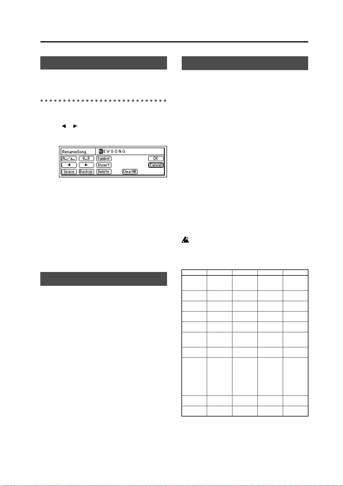
Change the name of the song.
Use the “ ” “ ” buttons to move the cursor to the
location of the character that you wish to change, and
rotate the [VALUE] dial to modify the song name.
The buttons in the LCD screen have the following
function.
“ A../a.. ” buttons: Select the alphabetical character
“A.” Press it again to select the lowercase “a”.
“ 0...9 ” button: Select the numeral “0–9”.
“
Symbol
“
Insert
ing characters backward.
“
Space
“
Backsp
cursor.
“
Delete
“
ClearAll
” button: Select a symbol.
” button: Insert a space, moving the follow-
” button: Select a space (blank).
” button: Delete the character before the
” button: Delete the character at the cursor.
” button: Delete the entire name.
3
has been changed as fol-
p.14
Part of “3. Selecting an existing song” has been
changed.
[STOP] key + [FF] key
Use this to select the previous or next-numbered song
in the same drive.
• Hold down the [STOP] key and press the [FF] key to
move to the end of that song. If you are already at
the end of the song, you will move to the beginning
of the next song.
p.36–
Fade Track and Normalize Track commands have been
added to “Track editing.”
Fade-in/Fade-out: Fade Track
This command creates a fade-in or fade-out in the
selected region ( IN – OUT ) of the recorded track data.
You can also create crossfades by combining fade-in
and fade-out for identical regions in two tracks.
• You can fade-in or fade-out the IN – OUT region.
• A single or multiple tracks of data can be faded-in or
faded-out simultaneously.
Boosting to an appropriate level: Normalize Track
If the recorded level is too low, you can use this command to boost the selected region (IN–
data to the maximum level that will not cause clipping.
• The peak value of the audio data in the IN–
region is detected, and the level of the entire IN–
OUT
region is boosted as far as possible without
causing the peak value to clip.
• The data of a single track or of adjacent tracks can be
normalized simultaneously.
If data that was recorded at an extremely low level
is normalized, any noise component it contains will
be boosted by the same amount.
The function of IN, OUT, TO, and END times for each command
Copy Track Copy source
Insert Trac k Blank insert
Erase T rac k Erase start
Delete T rac k Delete start
Swap T rac k Swap start
Reverse
Track
Optimize
Track
Expansion/
Compression T rac k
Fade Track Fade start
Normalize
Track
IN OUT TO END
start time
start time
time
time
time
Reverse
start time
Optimize
start time
Expand/compress start
time
time
Normalize
start time
Copy source
end time
Blank insert
end time
Erase end
time
Delete end
time
Swap end
time
Reverse end
time
Optimize
end time
Expand/compress end file
Fade end
time
Normalize
end time
OUT
) of track
OUT
Copy destination start
time
– – – – – –
– – – – – –
– – – – – –
– – – – – –
Reversed
copy destination start time
– – – – – –
Expand/compress destination start
time and
expand/compress result
copy destination start time
– – – – – –
– – – – – –
– – –
– – –
Expand/compress destination end
time
3
Page 6
p.40–
Change the “Tempo map” explanation in “Setting the
tempo.”
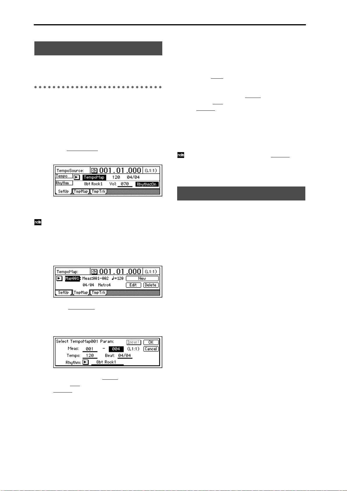
Tempo map
Tempo Map switches the tempo, time signature, and
rhythm pattern at the specified measure.
1
Specify Tempo Map as the tempo source.
• Select the [TEMPO/RHYTHM] “SetUp” tab
page.
• Press the “Rhythm” button to turn rhythm on.
• Press “T
to select “
empoSource,” and use the [VALUE] dial
TempoMap
.”
3
Add a tempo map at any point in the song where
you want to change the tempo, time signature, or
rhythm pattern.
• Press the “New” button to display “Select
TempoMap002 Param.”
• In the “Meas
(Start Measure) for which the tempo map will be
created, and the ending location (End Measure).
Specify the tempo in “T
ture in “Beat
“Rhythm
ing the previous data, turn off the “Insert” button.
• Press the “OK” button to add the tempo map.
The map numbers will automatically be reassigned from the beginning to the end of the
song.
By adding a tempo map and using “Rhythm
change the rhythm pattern, you can create drum
patterns for an entire song, including an intro, fillin, and ending.
” area, specify the starting location
empo,” the time signa-
,” and the rhythm pattern in
.” To add the tempo map by overwrit-
” to
2
At the beginning of the song, specify the initial
tempo in tempo map “001.”
T empo map “
song, and specifies the initial tempo. Tempo maps
“
002
”–“
of the song to change the tempo.
• Select the [TEMPO/RHYTHM] “TmpMap” tab
page.
• Select “T
to select tempo map “
• Press the “Edit” button to access the “Select
TempoMap001 Param” dialog box.
001
” is located at the beginning of the
200
” can be placed in successive measures
empoMap,” and use the [VALUE] dial
001
.”
p.43–
It is now possible to backup and restore song data
using a CD-R or CD-RW.
• Specify the tempo in “T
ture in “Beat
“Rhythm
It is not possible to change the starting location
(Start Measure) of tempo map “
change only the ending location (End Measure).
• After you have finished making the settings,
press the “OK” button.
,” and the rhythm pattern in
.”
empo,” the time signa-
001
4
.” Y ou can
Page 7
Reference
2. SYSTEM
p.45
The symbol indicating foot switch polarity has been
changed to “ ”.
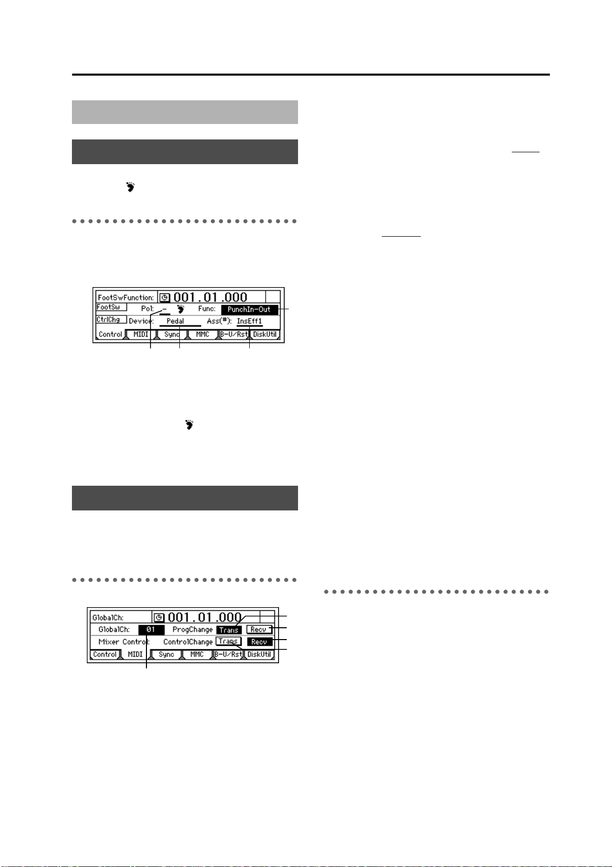
P1 Control: Foot switch/Control
change device (pedal/MIDI)
setting
2
3
1
1. Pol (FootSwPolarity)......................................... [–, +]
Specifies the polarity of the foot switch.
Connect a foot switch (such as the separately sold PS-1
option) to the front panel [FOOT SWITCH] jack, and set
this parameter so that the “ ” symbol appears when
the foot switch is pressed.
Refer to the D16 Owner’s Manual for details on 2, 3,
and 4.
4
1. GlobalCh (Global Channel)......................... [01...16]
Specifies the global MIDI channel.
This setting is required in the following cases.
• If you wish to control the effect by setting “Device
(P1-3) to a MIDI message other than “ Pedal .”
• If you wish to transmit/receive program change
messages to select scenes.
MIDI messages can be transmitted and received when
you connect the D16V2 to the external MIDI device via
MIDI and set the MIDI channel of the connected device
to match the “GlobalCh
2. ProgramChange: Trans...............................[On, Off]
This enables transmission of program change messages.
Program changes are transmitted when you change
scenes, or store/recall a scene.
3. ProgramChange: Recv................................[On, Off]
This enables reception of program change messages.
When a program change message is received, the scene
will change.
4. ControlChange: Trans.................................[On, Off]
This enables transmission of control change messages.
When you modify a mixer parameter, the correspond-
ing control change will be transmitted.
Control changes transmitted from the D16V2 can be
recorded on a MIDI-connected external sequencer. The
data recorded on the external sequencer can then be
played back to automate the mixer parameters.
” of the D16V2.
”
p.46–47
MIDI messages (control changes) can now be used to
control mixer parameters.
An “MMC” tab page has been added.
P2 MIDI: MIDI settings
1
The D16V2 lets you use MIDI to do the following
things.
• Control effects ( → D16 p.33)
• Synchronize with a sequencer or other MIDI device
• Select scenes (→D16 p.67)
• Use control changes to control mixer parameters.
5. ControlChange: Recv..................................[On, Off]
This enables reception of control change messages.
By receiving control changes that were previously
recorded on a MIDI sequencer, you can control the corresponding mixer parameters. For details on the
parameters that can be controlled, refer to the MIDI
implementation chart (→p.21).
P3 Sync: Synchronization settings
2
3
5
4
By synchronizing the D16V2 and an external MIDI
sequencer, you can simultaneously play back 16 tracks
of audio together with external MIDI tone generators.
The action of making the D16V2 operate at the same
timing as a MIDI sequencer is called synchronization .
The device that outputs the synchronization clock is
called the master device, and the device that receives
the synchronization clock is called the
D16V2 can function either as the master or the slave.
It is also possible to transmit MMC messages from a
MIDI sequencer etc. to control playback or recording on
the D16V2.
slave
device. The
5
Page 8
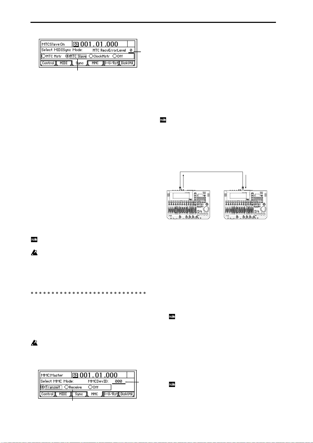
1
1. Select MIDISync Mode .............................................
[MTC Mstr, MTC Slave, Clock Mstr, Off]
Select the synchronization messages that will be transmitted and received from the MIDI IN/OUT connectors.
MTC Mstr
device for MTC 30 NDF (MIDI time code 30 non-drop
frame) messages.
MTC Slave
device for MTC 30 NDF (MIDI time code 30 non-drop
frame) messages.
ClockMstr
sages.
Off
zation messages.
: The D16V2 will function as the master
: The D16V2 will function as the slave
: The D16V2 will transmit MIDI Clock mes-
: The D16V2 will not transmit or receive synchroni-
1. Select MMC Mode .................[Transmit, Receive, Off]
Select the MMC mode.
2
Transmit
Receive
Off
: MMC will be transmitted.
: MMC will be received.
: MMC will not be used.
2. MMCDevID (MMC Device ID) ...................[000...127]
Specifies the device ID that will be used when transmitting/receiving MMC to/from the external MIDI device.
To enable MMC transmission/reception, connect the
external MIDI device to the D16V2 via MIDI, set the
device ID to match, and set “Select MMC Mode” appropriate.
If this parameter is set to “127,” MMC can be transmitted/received to/from all ID numbers.
Synchronizing two D16V2 units
Here’s how you can synchronize two D16V2 units. One
D16V2 will be the master, and the other will be the
slave.
Make connections as follows.
2. MTC RecvErrorLevel...................................... [0...10]
Specify the MTC check level used if “SelectMIDISyncMode” is set to “
MTC Slave
.”
If, due to some problem, MTC messages are not sent
consecutively to the D16V2, the D16V2 will detect the
abnormal MTC state and may stop synchronization and
halt playback. In such cases, you can lower the “MTC
RecvErrorLevel” setting so that synchronized playback
will continue even if some problems occur with MTC
reception.
If this is set to “0,” synchronized playback will not
stop even if a problem occurs.
Depending on the compatibility between the two
devices when a device other than the D16V2 is
used as the MTC master for synchronization, correct synchronization may not be possible unless
you start from the beginning of the song.
P4 MMC: MMC settings
The D16V2 supports MMC (MIDI Machine Control).
When synchronizing two D16V2 units, or when using
the D16V2 together with an MMC-compatible MIDI
sequencer, you can playback, stop, or fast-forward etc.
by operating only the master device.
Some MIDI devices may not respond to the MMC
functionality of the D16V2. Details on the MMC
functionality of the D16V2 are given in the MIDI
implementation.
2
MIDI
IN
MTC
MMC
“MTC Slave”
“Receive”
MTC
“MTC Mstr”
“Transmit”
MMC
MIDI
OUT
D16V2 (Master) D16V2 (Slave)
1
Make settings on the master D16V2.
In the [SYSTEM] “Sync” tab page, set “Select MIDI
SyncMode” to “ MTC Mstr .” In the [SYSTEM]
“MMC” tab page, set “Select MMC Mode” to
“Transmit.” For this example, set “MMC DevID”
to “10.”
2 Make settings on the slave D16V2.
In the [SYSTEM] “Sync” tab page, set “Select MIDI
SyncMode” to “MTC Slave.” In the [SYSTEM]
“MMC” tab page, set “Select MMC Mode” to
“Receive.” For this example, set “MMC DevID” to
“10” (the same as the master).
Press the [PLAY] key on the slave D16V2 to put it
in playback-ready mode.
If you do not want to receive mixer control
data, you can either turn the [SYSTEM]
“MIDI” page “Control Change: Trans” parameter “Off” on the master D16V2, or turn the
[SYSTEM] “MIDI” page “Control Change:
“Recv” parameter “Off” on the slave D16V2.
3 Press the [PLAY] key on the master D16V2.
When the slave D16V2 receives time code and
establishes synchronization with the time code of
the master unit, the slave D16V2 will begin playback.
Several seconds may be required in order for
synchronization to be established.
1
6
Page 9

On the MTC slave D16V2, you must make sure
that the [AUTOPUNCH] “AtPunch” tab page
“AutoPunch” parameter and the [LOOP]
“Loop” tab page “Loop” parameter are both
turned “Off.”
p.49–
D8 backup data can now be restored into the D16V2.
P5 B-U/Rst: Backup/restore from
removable disk
3. Format Type........................................... (P, B, D8[B])
This displays the format type of the drive.
The internal drive of the D16V2, or an external drive
connected to the D16V2 and initialized or formatted,
will be displayed as a playable drive. Other drives will
be displayed as backup drives.
[P] (Playable type): A disk for creating D16 songs
[B] (Backup type): A disk for backing up D16 data
D8 [B]: A D8 backup disk
Format: Format the drive selected by “Drive ID.”
Here you can backup (save)/restore (recall) data using
a removable disk. The D16V2 supports backup/restore
on CD-R or CD-RW. The following data can also be
restored.
• D16 backup data
• D8 backup data (audio data only)
Be aware that backup and some restore operations
will overwrite the data on the destination drive.
When backing up on CD-R or CD-RW, you must
use a blank disk.
p.47–
Format types have been added to the display.
A “Force” button has been added for forcible initialization.
P6 DiskUtil: Initialize/format/
check a drive
Here you can initialize, format, or check a drive.
Before a disk can be used to record/playback for the
first time, it must be initialized or formatted.
• Initialize a drive when you wish to erase the con-
tents of the drive and use it for the first time, such as
for a newly purchased drive.
• Format a disk previously used by another device
before using it on the D16V2, or if “DiskError” messages begin to appear frequently during playback.
It is not necessary to initialize/format a removable
disk that will be used for backup/restore.
When you initialize or format a drive, the data on
that drive will be lost.
1
4
Force.........................................................[On, Off]
On: Even if the disk contains a song or songs protected by “Protect Song,” initialization will be performed forcibly.
Off: If the disk contains a song or songs protected
by “Protect Song,” a message of “Song Protect” will
be displayed when you attempt to initialize, and
the command will be aborted.
4. TRACK
p.53–
The edit type name has been changed from “***Trk” to
“***Track.”
p.54
The explanation for Optimize Track has changed as follows.
Optimize Track: This optimizes the track data in the
IN–OUT range of the destination track (“DestT
The D16V2 will not generate unnecessary sound if the
IN–OUT range contains unused blank portions. However in the case of brief blank portions that are close to
the next audio event, the data will be generated as a
single sound to avoid producing “Disk Busy” errors.
By executing Optimize with IN–OUT set to the
beginning and end of the song, you can ensure that
the data will be accessed with ideal efficiency from
the hard disk.
1
3
rack”).
7
6
2
Refer to the D16 Owner’s Manual for details on 1, 2,
and 4.
3
7
Page 10

IN OUT
DestTrack
DestTrack
p.56–
Fade Track and Normalize Track have been added as
edit types.
EditType: “FadeTrack”
This command creates a fade-in or fade-out in the IN–
OUT region of the fade-in destination track (“Dest-
Track”) data. When this is executed, the audio data of
the IN–OUT region will be smoothly faded in toward
the level at the OUT location.
When this is executed (“Exec.”), the fade-in destination track will be overwritten.
1 7
3
IN OUT
8
IN OUT
Fade-in procedure
As an example, here’s how to fade-in the IN–OUT
region of track 1.
1 Select the IN and OUT locations.
Select/assign the fade-in start and locations.
(→D16 p.70)
2 Select the Fade Track edit type.
In the [TRACK] “EditT rk” tab page, set “EditType”
to “FadeTrack.”
3 Select the fade curve.
Press the “Mode” button to access the dialog box.
For this example, select the “A type” curve, and
press the “OK” button to return to the [TRACK]
“EditTrk” tab page.
4 Select the fade-in destination track number.
Set “DestTrack” to track “1.”
5 Execute the fade-in.
Press the “Exec.” button, then reply to the “Are You
Sure?” confirmation. When the fade-in is completed, the display will indicate “Completed.”
Press the “OK” button.
6
6 Listen to the results.
Press the [IN/LOC1] key to play back from the IN
location, and check that the fade-in was performed
correctly.
You can use Undo to return the data to the state
before the operation was executed.
The time required by this editing operation
before the “Completed” display appears will
take proportionally longer as the specified
range (IN–OUT) is longer.
8. MODE.....................................................................
Select the fade curve with which the fade-in or fade-out
will be performed.
SelectFadeMode............................................. [A...F]
A type: This curve is ideal for conventional fade-in.
B type: This curve is ideal for creating cross-fades
where two tracks are faded-in/out at the identical
time location.
C type: This curve inverts the A curve, lengthening
the sound that is heard before the fade.
D type: Fade-out using the A type curve.
E type: Fade-out using the B type curve.
F type: Fade-out using the C type curve.
Press the “OK” button to finalize the selected fade
type.
Press the “Cancel” button to cancel the setting.
Fade-out procedure
Here’s how to fade-out the IN–OUT region of track 1.
1 Select the IN and OUT locations.
Select/assign the fade-out start and locations.
(→D16 p.70)
2 Select the Fade Track edit type.
In the [TRACK] “EditT rk” tab page, set “EditType”
to “FadeTrack.”
3 Select the fade curve.
Press the “Mode” button to access the dialog box.
For this example, select the “D type” curve, and
press the “OK” button to return to the [TRACK]
“EditTrk” tab page.
4 Select the fade-out destination track number.
Set “DestTrack” to track “1.”
5 Execute the fade-out.
Press the “Exec.” button, then reply to the “Are You
Sure?” confirmation. When the fade-out is completed, the display will indicate “Completed.”
Press the “OK” button.
6 Listen to the results.
Press the [IN/LOC1] key to play back from the IN
location, and check that the fade-out was performed correctly. You can use Undo to return the
data to the state before the operation was executed.
8
Page 11

The time required by this editing operation
(i.e., before the “Completed” display appears)
will take proportionally longer as the specified
range (IN–OUT) is longer.
EditType: “NormalizeTrack”
This command searches for the peak level of audio data
that was recorded at an unintentionally low level, and
boosts the entire region of audio data so that this peak
level will be the maximum level.
When this command is executed (“Exec.”), the normalize destination track will be overwritten.
1
7
6
3
IN OUT
Max Level
3. DestTrack.................................. [1...16, 1-2...15-16]
Selects the normalize destination track.
For a 24 bit song, only up to tracks 7-8 can be
selected.
6. Exec. (Execute).........................................................
Executes the track editing command.
IN OUT
Max Level
Normalizing procedure
Here’s how to normalize the IN–OUT region of track 1.
1 Select the IN and OUT locations.
Select/assign the starting and ending times of the
region that you wish to normalize. (→D16 p.70)
2 Select the Normalize command.
In the [TRACK] “EditT rk” tab page, set “EditType”
to “NormalizeTrack.”
3 Select the normalize destination track number.
Set “DestTrack” to track “1.”
4 Execute the Normalize command.
Press the “Exec.” button, and respond to the “Are
You Sure?” display. When the operation is completed, the display will indicate “Completed.”
Press the “OK” button.
5 Listen to the result.
Press the [IN/LOC1] button to play back from the
IN location, and verify that the Normalize operation was performed correctly.
You can use Undo to return the data to its previous
state.
The time required by this editing operation
(i.e., before the “Completed” display appears)
will take proportionally longer as the specified
range (IN–OUT) is longer.
p.58–
An “Import” tab page and “Export” tab page have been
added.
P4 Import: Import a WAVE file
A WAV file saved on a FAT 16 DOS format external
SCSI device can be loaded into the beginning of a
D16V2 track. (→p.20 “Note when using DOS format
disks”)
You can also import this data into the clipboard, and
paste it into a location other than the beginning of the
track.
In the case of CD-ROM, CD-R, and CD-RW, the
D16V2 supports WAV files saved on ISO9660 format discs. Sub-directories are also supported for
CD-ROM, CD-R, and CD-RW.
For external SCSI drives other than CD-ROM, CDR, and CD-RW, the D16V2 supports only WAV files
that are saved in the root directory of the first partition of FAT 16 format.
The D16V2 can import WAV files of the following
formats.
Sampling frequency: 44.1 kHz
Quantization: 8 bit, 16 bit, 24 bit
Number of channels: 1, 2 (monaural or stereo)
When this command is executed (“Exec.”), the
import destination track will be overwritten.
A certain amount of time is required when importing or exporting W AV files. Her e are some example
times when importing or exporting a five-minute
16 bit 44.1 kHz monaural WAV file from/to a Zip
drive.
Importing: approximately 9 minutes 20 seconds
Exporting: approximately 10 minutes 30 seconds
* The processing time will differ depending
on the format of the WAV file and on the
SCSI device you are using.
5
1 3
2 4
1. DriveList.........................................................[A...G]
Select the drive. For details on the drive numbers, refer
to “Drive ID” (→D16 p.47).
2. WavFileList .............................................................
Select the WAV file.
Press the “OK” button to finalize the setting, press the
“Cancel” button to cancel the setting.
9
Page 12

2a. Prvw ................................................................
You can preview the first two seconds of the
selected WAV file.
If you select a WAV file of an unsupported format,
one of the following error messages will appear.
SAMPLE RATE NOT 44.1k: This will
appear if the sampling frequency of the WAV file is
other than 44.1 kHz.
SAMPLE BIT NOT FIT: This will
appear if the quantization of the WAV file is other
than 8 bit, 16 bit, or 24 bit.
ILLEGAL WAV DA TA: This will appear
if the WAV file is unsupported for a reason other
than the above (perhaps a form of data compression etc.).
Sub-directories are also supported when
importing from CD-ROM, CD-R, or CD-RW.
Sub-directories are indicated as [...] in the WavFileList screen.
To enter this directory, select [...] and press the
“OK” button. To return, select “←” and press
the “OK” button.
Press the “WavFileList” button to access the dialog
box. For this example, select “A:Sound001.wav,”
and press the “OK” button to return to the
[TRACK] “Import” tab page.
Sub-directories are supported if you are importing
from a CD. If you are importing from another SCSI
drive, only WAV files saved in the root directory
are supported.
You can use the “Prvw” button to audition the first
two seconds of the selected WAV file.
4 Select the import destination track number.
Set “DestTrack” to track “1.”
5 Execute the import.
Press the “Exec.” button, and respond to the
“AreYouSure?” display. When the import is completed, the display will indicate “Completed.”
Press the “OK” button.
6 Listen to the result.
Hold down the [STOP] key and press the [REW]
key to return to the beginning of the song, and listen to the data to verify that it was imported correctly. You can use Undo to return the data to the
previous condition.
The longer the file being imported, the more
time will be required for this operation (i.e.,
before the “Completed” display appears).
3. DestTrack........................ [1...16, 1-2...15-16, Clip#]
Selects the import destination track.
Clip# will be 1 if the selected W AV file is monaural, or 2
if the file is stereo.
4. FileType.........................................................[M, St]
This indicates whether the selected WAV file is monaural or stereo.
Mono: The selected WAV file is monaural.
Stereo: The selected WAV file is stereo.
5. Exec. (Execute) ........................................................
Executes the WAV file import command.
Importing a W AV file to the beginning of a
track
Here’s how a monaural WAV file named
“Sound001.wav” can be imported into the beginning of
track 1 from a DOS format external drive “A: DOS”
connected to the SCSI connector.
1 Select Import.
Select the [TRACK] “Import” tab page.
2 Select the import source drive.
Press the “DriveList” button to access the dialog
box. Select the DOS format drive that contains the
WAV file. For this example select drive “A,” and
press the “OK” button to return to the [TRACK]
“Import” tab page.
3 Select the WAV file.
Importing a WAV file to the middle of a
track
Here’s how a monaural WAV file named
“Sound001.wav” can be imported once into the TO
location of track 1 from a DOS format external drive
“A: DOS” connected to the SCSI connector.
1 Select Import.
Select the [TRACK] “Import” tab page.
2 Select the import source drive.
Press the “DriveList” button to access the dialog
box. Select the DOS format drive that contains the
WAV file. For this example select drive “A,” and
press the “OK” button to return to the [TRACK]
“Import” tab page.
3 Select the WAV file.
Press the “WavFileList” button to access the dialog
box. For this example, select “A:Sound001.wav,”
and press the “OK” button to return to the
[TRACK] “Import” tab page. Sub-directories are
supported if you are importing from a CD. If you
are importing from another SCSI drive, only WAV
files saved in the root directory are supported.
4 Select the clipboard as the copy destination track
number.
Set “DestTrack” to “Clip.”
5 Execute the import.
Press the “Exec.” button, and respond to the
“AreYouSure?” display. When the import is completed, the display will indicate “Completed.”
Press the “OK” button.
The longer the file being imported, the longer
the time that will be required for this operation
(i.e., before the “Completed” display appears).
10
Page 13

6 Specify the TO time location.
(→D16 p.70)
7 Select Copy.
In the [TRACK] “EditT rk” tab page, set “EditType”
to “Copy Track.”
8 Select the clipboard as the copy source track num-
ber.
For “SourceTrack,” select “Clip 1.” The number
indicates the number of tracks in the clipboard.
9 Select the copy destination and track number.
Set “DestTrack” to track “1.”
0 Specify the number of times that the data will be
copied.
Set “Times” to “1” copy.
A Execute the copy operation.
Press the “Exec.” button, and respond to the
“AreYouSure?” display. When the copy is completed, the display will indicate “Completed.”
Press the “OK” button.
The data will be overwritten onto the copy
destination track.
B Listen to the result.
Press the [TO/LOC3] key to play back from the TO
time location, and listen to the data to verify that it
was imported correctly. You can use Undo to return
the data to the previous condition.
3. Rename..................................................................
Press the “Rename” button to access the dialog box,
and specify a name for the W AV file. Up to eight characters can be used in the WAV file name.
4. Exec. (Execute)........................................................
Execute the WAV file export.
4a. Export Size ..................................[16 bit, 24 bit]
This can be selected only if the clipboard contains 24 bit data.
Specify whether the 24 bit data copied to the clipboard will be exported as a 16 bit WAV file or as a
24 bit WAV file.
4b. Dither SW..........................................[ON, OFF]
This can be selected only for 24 → 16 bit.
Specify whether dithering will be performed when
the 24 bit data copied to the clipboard is exported
as a 16 bit WAV file.
P5 Export: Export a WAV file
Audio track data copied to the clipboard of the D16V2
can be exported to a W AV file (16 bit, 44.1 kHz, mono or
stereo) on a FAT 16 DOS formatted external SCSI drive.
(→p.20 “Note when using DOS format disks”)
Clip board data in 24 bit mode can be exported either as
16 bit or 24 bit data. When exporting 24 bit clipboard
data as 16 bit data, you can select whether dithering
will be performed.
If dithering is performed, quantization noise will
be less obvious.
It is not possible to export to a CD device (CD-R,
CD-RW).
5
1
2 43
1. Clip#.......................................................................
This shows the state of the clipboard. # indicates the
number of tracks in the clipboard. Only Clip1 (monaural) or Clip2 (stereo) can be exported.
ON: Dithering will be performed in order to make
quantization noise less obtrusive.
OFF: Dithering will not be performed.
5. Date .......................................................................
Input the date of the W AV file being exported. Press the
“Date” button to access the dialog box, and specify the
date on which the WAV file was created. Directly press
the date that you wish to change, and use the [VALUE]
dial to modify the date.
Press the “OK” button to finalize the setting. Alternatively, press the “Cancel” button to cancel any changes
you made.
2. DriveList ........................................................[A...G]
Select the drive. For details on drive numbers, refer to
“Drive ID” (→D16 p.47).
11
Page 14

Exporting to a WAV file
Here’s how the IN–OUT range of tracks 1 and 2 from
song 001 can be exported to a SCSI-connected DOS format external drive “A:DOS” as a stereo WAV file
named “Sound001.wav.”
1 Select song 001.
2 Assign the IN and OUT time locations.
(→D16 p.70)
3 Select Copy.
In the [TRACK] “EditT rk” tab page, set “EditType”
to “CopyTrack.”
4 Select the copy source track number.
Set “SourceTrack” to tracks “1-2.”
5 Select the clipboard as the copy destination track
number.
Set “DestTrack” to “Clip.”
6 Execute the copy.
Press the “Exec.” button, and reply to the “Are You
Sure?” message. When the copy is completed, the
display will indicate “Completed.” Press the “OK”
button.
7 Select Export.
Select the [TRACK] “Export” tab page.
8 Select the export destination drive.
Press the “DriveList” button to access the dialog
box. Select a DOS format drive. For this example,
select drive “A” and press the “OK” button to
return to the [TRACK] “Import” tab page.
9 Assign a name to the WAV file.
Press the “Rename” button to access the dialog
box, and modify the name. Y ou can input a name of
up to eight characters.
A filename extension of .wav will be input
automatically.
0 Input date information for the WAV file.
Press the “Date” button to access the dialog box,
and input the year, month, day, hour, minute, and
second.
A Execute the export operation.
Press the “Exec.” button, and reply to the “Are You
Sure?” message. When the data has been exported,
the display will indicate “Completed.” Press the
“OK” button.
If an identically-named WAV file already
exists, the export operation cannot be executed.
5. SONG
p.62
An “Erase” button has been added to the “CDR/RW”
tab page.
P4 CDR/RW: Creating and playing
a CD-R/RW
1
2
3
7
Refer to the D16 Owner’s Manual for details on 2–6.
1. CD-R/RW Information .............................................
[Trk01...99, BlankDisc, NoAudioTracks, NoDrive]
This displays the song that will be played from the CDR/RW disc.
Trk01...99: The song number within the CD-R/RW disc.
BlankDisc: Nothing has been written to the inserted
CD-R/RW disc.
NoAudioTracks: Either a CD-R/RW disc has not been
inserted, or no playable audio tracks were found on the
disc.
NoDrive: No drive is connected.
7. Erase ......................................................................
This erases the data that was written on the CD-RW.
This cannot be executed for a CD-R.
Be aware that erased data cannot be recovered.
4
8. SCENE
p.65–
The “ReadDel” tab page has been changed.
6
5
12
P1 ReadDel: Scene playback on/
off and editing
1
2
4 5 3
8
6
7
9
10
Page 15

On
On
1. SceneRead ................................................ [On, Off]
This turns scene playback on/off.
: Scenes will be played back. The
mixer settings will change automatically when playback reaches the time location at which a scene was registered.
When “On,” the [SCENE] key will light.
Off
: Scenes will not be played back.
In this case, scenes can be freely recalled as general-purpose settings whenever you wish. (→D16 p.66 “Recalling a scene”)
2. Filter .......................................................................
You can use filters to disable specific mixer settings
(parameters) when registering or playing back a scene.
Here you can specify which mixer settings (parameters)
will be disabled.
If “SceneRead” (P1-1) is “
scene you wish. If it is “On,” the scene for the current
time location will be selected, and cannot be changed.
4. Sort........................................................................
This sorts the scenes in order of time.
Normally, scenes are arranged in the order in which
they were registered, but you may sort them in ascending order of registered time.
5. Rename..................................................................
Here you can modify the scene name.
Use “SceneNumber
you wish to change, press the “Rename” button, and
modify the name in the dialog box. A name of up to 16
characters can be input. (→p.3 D16 p.14)
In addition to being shown in the “ReadDel” tab page,
the scene name will also be shown in the [SONG] “SelSong” tab page if “Select DispParameter
is set to “
Scene
.” (→D16 p.59)
Off
,” you may select any
” to recall the scene whose name
” (in that page)
On
: The filter will be turned on for the corresponding
channel/parameter, and the scene settings will be disabled.
Off
: The filter will be off, and the scene settings will be
enabled.
When registering, the filter acts as a registration filter
for the song.
When playing back, the filter acts as a playback filter
for the song.
For example, suppose that you turned the “Pan” filter
on for channels 1 and 2, and registered a scene “002” in
the middle of the song. We will also suppose that you
turned on the “EQ” filter during playback.
When you set “SceneRead” to “On” and play back
from the beginning of the song, the pan settings will not
be recalled when you reach scene “002” because the
“Pan” filter is on. In other words, the same pan values
as in scene “001” (located at the beginning of the song)
will continue in effect, but the remaining parameters
will change to the values of scene “002.” “EQ” settings
are being played back through the playback filter, so
the values registered in the scene at the beginning of
the song will not be used; the current EQ values will be
maintained.
3. SceneNumber.........................................[001...100]
Recalls the mixer settings of the selected scene at the
current time.
This is also used to select a scene when you wish to
change its name or modify the time at which it is registered.
The time at which the scene is registered is displayed
beside “SceneNumber.”
6. EditLoc....................................................................
Modifies the registered time of a scene.
Use “SceneNumber
you wish to modify.
Press the “EditLoc” button to access the dialog box, and
modify the time at which the scene is registered.
Press the time value that you wish to change, and use
the [VALUE] dial to change the time. Press the “OK”
button to confirm your settings, or press the “Cancel”
button to cancel the settings you made.
7. Delete.....................................................................
This deletes a scene.
When you delete a scene, the Undo operation is not
available.
” to access the scene whose time
7a
7a. SelectAll ..............................................[On, Off]
: All scenes will be subject to dele-
tion. The scene number will be shown as “***”.
Off : The single scene selected for
“SceneNumber” will be subject to deletion.
8. EdtFiltr....................................................................
Views or modifies the settings of the filter register ed for
the scene.
When a scene is stored, it saves all the parameters that
can be registered, as well as the state of the filter.
If the filter is defeated, you can enable scene data to be
13
Page 16

recalled even after storing the scene.
If the filter is enabled, you can disable recall of scene
data even after storing the scene.
9. Recall .....................................................................
This recalls the settings that were stored in a scene.
If you recall a scene, edit the EQ etc., and then press the
“Recall” button to recall once again, the unedited settings (the mixer settings that were registered in the
scene) will be recalled.
10.OvrWrt...................................................................
This overwrites the current mixer settings onto the
selected scene number. Use this when you wish to
make minor changes to a scene, or to replace it with
another scene.
Pan
: The pan knob is more than 51 steps to the left of the
internal value.
: The pan knob is between 21–50 steps to the left of
the internal value.
: The pan knob is between 1–20 steps to the left of the
internal value.
: The pan knob matches the internal value.
: The pan knob is between 1–20 steps to the right of
the internal value.
: The pan knob is between 21–50 steps to the right of
the internal value.
: The pan knob is more than 51 steps to the right of
the internal value.
p.67–
A guide function has been added for the pan and faders.
P2 MixView: Pan/fader scene
display
1
2
4
Refer to the D16 Owner’s Manual for details on 1–3.
4. Pan/fader guide ...............[ ]
These symbols show the difference between the actual
fader or pan locations and the values that are registered
in the scene.
When a scene is recalled, the current position of the faders may differ from the values registered in the scene.
In this case, selecting the item that you wish to adjust
will cause an indicator symbol to appear, showing the
approximate difference between the internal setting
value and the control.
Faders
: The fader position is more than 51 steps above the
internal value.
: The fader position is between 21–50 steps above the
internal value.
: The fader position is between 1–20 steps above the
internal value.
: The fader position matches the internal value.
: The fader position is between 1–20 steps below the
internal value.
: The fader position is between 21–50 steps below the
internal value.
: The fader position is more than 51 steps below the
internal value.
3
9. TEMPO/RHYTHM
p.68–
Part of the “SetUp” tab page has been changed.
P1 SetUp: Tempo and rhythm
settings
1
4 5 2
Refer to the D16 Owner’s Manual for details on 1–4 and
6.
5. RhythmVol ............................................. [000...100]
Specifies the volume of the rhythm. This volume will be
sent to the master LR bus if the [SOLO/MONITOR]
“Monitor” page “Rhythm” button is turned off. If this
button is on, the volume will be sent to the monitor LR
bus. (→D16 p.17)
7. Pattern Length, Pattern Position................................
This shows the length (number of measures) of the
rhythm pattern selected by “SelRhythm,” and the measure that is currently playing.
Example: (L4:1)... currently playing measure 1 of a
four-measure pattern
7
3
6
14
Page 17

P2 TmpMap: Tempo map editing
By specifying tempo maps you can change the tempo,
time signature, and rhythm pattern while recording or
playing a song.
Changes in tempo, time signature, and rhythm can
be placed only at the beginning of each measure.
For details on creating a tempo map, refer to p.4.
1
3
2f. Insert....................................................[On, Off]
On: The new tempo map will be created in Insert
mode, inserting the tempo map.
Off: The new tempo map will be created in Overwrite mode, overwriting the existing tempo map.
3. Edit ........................................................................
Modifies the settings of the tempo map.
Select this when you wish to modify a previously-created map. Use “T
5
2
wish to modify, and then press this button. The “Select
Tempo Map *** Param” dialog box will appear, allowing you to set the various parameters. (→”New”)
empoMap” to select the map that you
4
4. Delete.....................................................................
This deletes the tempo map.
1. TempoMap.............................................[001...200]
This is the number of the selected tempo map. The
starting measure, ending measure, tempo, time signature, and rhythm pattern of this tempo map are shown
at the right.
You can press the “ ” button and select from a dialog
box.
“T empoMap” cannot be selected if “TempoSource”
(→P1-1) is “Manual.”
2. New........................................................................
Creates a new tempo map.
You will also create a new tempo map when you wish
to add a tempo map between existing tempo maps.
The following “SelectTempo Map***Param” dialog box
will appear.
2a
2c
2e
2a. StartMeas.........................................[001...999]
Specifies the starting location of the tempo map.
This is specified in units of a measure.
2b. EndMeas..........................................[001...999]
Specifies the ending location of the tempo map.
This is specified in units of a measure.
2c. Tempo.................................................[40...240]
Specifies the tempo. The units are =40–240.
2d. Beat......................................... [01/04...16/16]
Specifies the time signature.
2e. Rhythm............................. [(Rhythm Pattern List)]
Specifies the rhythm. If you want part of the
rhythm to be silent, select a silent rhythm type.
Y ou can pr ess the “ ” button and select from a dialog box.
The rhythms that can be selected will depend on
the “Beat
.” (→D16 p.114)
2d
2b 2f
4a
4a. SelectAll ..............................................[On, Off]
Selects which tempo maps will be deleted.
On: All tempo maps will be deleted.
The tempo map number will be displayed as “***”.
Off: The single tempo map selected for
“T
empoMap” will be deleted.
On the D16V2, all tempo maps following the
deleted tempo map will be moved forward.
5. Pattern Length, Pattern Position ...............................
This shows the number of measures (length) of the pattern selected by “SelRhythm,” and the measure number
that is currently playing.
13. UNDO
p.73
An undo level setting has been added.
The scroll buttons have been changed to “New” and
“Old” buttons.
After executing the following operations, you can use
Undo to return to the condition prior to executing the
operation. You may then use Redo to return to the condition prior to executing Undo.
• Recording
• Track editing
Copy Track, Insert Track, Erase Track, Delete Track,
Swap Track, Reverse Track, Optimize Track, Exp/
Comp T rack, Copy Whole Track, Swap Whole Track,
Fade T
rack, Normalize Track
•WAV file import
2
1
5
3
4
76
15
Page 18

Refer to the D16 Owner’s Manual for details on 1–4.
5. Level................................[99 Level, 8 Level, 1 Level]
Specifies the undo level. The data will be saved for the
specified number of previously-executed operations.
You can select the undo level from 99, 8, or 1 operations.
6. New.......................................................................
Scroll the list toward the newer data.
7. Old.........................................................................
Scroll the list toward the older data.
19. INSERT EFFECT
■ When “Assign” is set to “Trk”
Specifies the channel into which the effect will be
inserted: → (effect) → (return=inserted channel).
3a. SelectCh..........................................[1...16, Off]
Selects the mixer channel into which the effect will
be inserted.
If the “SelectEffType” is “2in2outx2,” only
odd-numbered channels can be selected for
“SelectCh.”
3b. Effect .......................................................(1...8)
This shows the insert effect number.
3c. OutputCh......................................... [1...16, Off]
This shows the return channel of the effect output.
The same channel as “3a. SelectCh” will be shown.
p.79–
Some of the operations have been changed.
P1 InsASS: Insert effect insert
position/type setting
1
23
Refer to the “D16 Owner’s Manual” for details on 1, 2,
and 4.
3. InsertTo...................................................................
Selects the position at which the insert effect will be
inserted.
Press the “ ” button to access the dialog box, and
make settings. Press the “OK” button to finalize the settings, or press the “Cancel” button to discard any
changes you made.
3a
21. SOLO/MONITOR
p.84
“Rhythm Level” has been deleted from “P2 Monitor:
Monitor settings.”
4
1
2
Refer to the D16 Owner’s Manual for details on 1, 2,
and 4.
5. Rhythm ......................................................[On, Off]
Selects whether the internal rhythm sound will be sent
to the monitor LR bus or to the master LR bus.
On: The internal rhythm sound will be sent to the monitor LR bus. It will not be sent to the master LR bus.
Off: The internal rhythm sound will be sent to the master LR bus. It will not be sent to the monitor LR bus.
The volume of the internal rhythm is adjusted by
“RhythmVol” in the [TEMPO/RHYTHM] “Setup”
page.
5
4
3c
3b
■ When “Assign” is set to “In”
Specifies the return channel.
3a. Input....................................... (In1...8, DrL, DrR)
This shows the analog inputs.
3b. Effect....................................................... (1...8)
This shows the effect numbers.
3c. SelectCh.......................................... [1...16, Off]
This specifies the return channel of the effect output.
16
Page 19

26. TRANSPORT KEY
p.87
Part of the operation of the [FF] and [REW] keys has
been changed.
These keys perform recorder operations such as playback and recording.
65
1234
Refer to the D16 Owner’s Manual for details on 4–6.
1. [FF] key
When stopped or playing, this key moves forward
in time (fast-forward).
If you hold down the [STOP] key and press the [FF]
key, you will move to the end of the current song. If
you are already at the end of the song, you will
move to the beginning of the next song.
If the Scrub function is on, you can press this key to
perform Slow Play (→D16 p.74).
2. [REW] key
When stopped or playing, this key moves backward
in time (rewind).
If you hold down the [STOP] key and press the
[REW] key, you will move to the beginning of the
current song (if you are in the middle of the current
song), or to the beginning of the previous song (if
you are already at the beginning of the current
song).
Appendices
p.106
The following messages have been added to “Error
messages.”
Unsupported File Type
When importing a WAV file, you attempted to import
an unsupported file.
→ Specify a WAV file that can be imported. (→p.9)
Same File Name Exists!
When exporting a WAV file, a WAV file of the same
name already exists in the export destination drive.
→ Specify a different filename.
No CDRW Disc
The erase destination media is not a CD-RW.
→ Execute the erase command on a CD-RW.
Drive Condition Error
If this message appears when an unfinalized CD is
played, it is possible that your drive does not support
unfinalized CD’s.
→ Finalize the disc before playing it.
If this message appears when using a CD-R/RW drive,
an error has occurred in the drive.
→ Check the drive connections. If no problem is found
with connections or operation, replace the media.
3. [STOP] key
This key stops recording or playback, and stops the
recorder.
17
Page 20

Regarding disk capacity
This section explains how the D16V2 manages disk
capacity.
For explanatory purposes, we will assume that you
have recorded a song with the following structure.
It is not necessary that the Optimize Track operation explained here be used frequently. It is sufficient to use it only if “Disk Busy” is displayed
when you are actually editing, or if you wish to
recover more disk free space after you have finished the song.
Example 2
Suppose that you began recording on track 1 from the
beginning of the song, and played the Intro, A, B, and
Solo as the first take. Then you recorded A’ and B’ as the
second take.
Take 1
Take 1
Take 2
Intro B SoloA
Record take 2
Intro B
A
B'A'
Solo
Intro A B BreakSolo Ending
Example 1
Suppose that you began recording on track 1 from the
beginning of the song, and recorded only the Intro,
Solo, and Ending as the first pass of recording.
Intro
silence Solo Ending
IN OUT
“EraseTrack”
silence
IN OUT
“EraseTrack”
In this case, sections A, B, and the Break will be
recorded as silence (in reality, sound at the noise level),
and will occupy disk space unnecessarily. Execute the
Erase Track operation on the silent portions (A, B, and
Break) of track 1. At this time, the D16V2 is only “provisionally” erasing the unwanted portions A, B, and
Break (the noise-level sound), meaning that the disk
capacity will not be recovered.
→ If you wish to retain only the audio data that you are
actually using (Intro, Solo, and Ending) and recover the
rest of the space, execute Optimize Track on track 1
between the beginning and end of the song. This will
create audio data for only the portions that are actually
used, so that only the Intro, Solo, and Ending will
occupy disk capacity.
Intro
data exists Solo Ending
data
exists
In this case, the A and B (take 1) data underlying A’ and
B’ of track 1 will remain as a single piece of audio data
together with the Intro and Solo, in order to allow Undo
to be performed. This means that the disk capacity will
be occupied by data for the Intro, A+A’, B+B’, and Solo.
→ If you wish to recover disk capacity by erasing the A
and B data from the first take, execute the Optimize
Track command on track 1 from the beginning to the
end of the song. This will create audio consisting only
of the Intro of take 1, A’ of take 2, B’ of take 2, and the
Solo of take 1. Sections A and B of take 1 will no longer
occupy disk capacity.
Intro
IN OUT
Intro
A
B
B'A'
“OptimizeTrack”
B'A'
Solo
Solo
IN OUT
Intro Solo Ending
data erased
“OptimizeTrack”
after execution
data
erased
18
Page 21

Example 3
BA
Take 1
Suppose that you recorded A and B on track 1 as the
first take. Then you overwrote the Intro, A’, B’, and Solo
as take 2.
Take 1
Intro B' SoloA'
Take 2
In this case, the take 1 data for A and B will remain
underlying A’ and B’ of track 1. However once take 2 is
finished, the audio data of take 1 will not be used at all,
so it is not necessary to perform the Optimize operation
etc.
Intro B' SoloA'
Even if you use disk capacity efficiently in the above situations (examples 1, 2, 3), the old data will remain on
the hard disk in order to allow Undo.
To erase the data that is maintained by the Undo function, turn off the power of the D16V2. When you turn
the power on once again, all data that had been maintained for purposes of Undo will be erased, thus allowing you to recover this disk capacity.
If before you executed Optimize Track, audio data was
used by other tracks (including virtual tracks) or by
another song on the same disk, the old audio data will
not be erased. This will cause even more disk space to
be occupied than before executing Optimize Track.
MIDI functions
On the D16V2, MIDI can be used to do the following
things.
(I) Control change messages can be used to con-
trol mixer parameters. (Refer to “Using mixer
control”)
(II) Effect parameters can be controlled via MIDI.
(→ D16 p.45)
(III) Program change messages can switch mixer
scenes. (→D16 p.67, D16V2 →[SYSTEM]
“MIDI” section)
(IV)MMC can be used to control external MIDI
devices, or to control the D16V2 from an external MIDI device. (→D16 p.46, D16V2 [SYSTEM] “MMC” section)
(V) MTC can be used to synchronize the D16V2
with external MIDI devices. (→D16 p.46,
D16V2 [SYSTEM] “SYNC” section)
Using mixer control
In the [SYSTEM] “MIDI” page, you can turn on “Control Change “T rans” and “Recv” to transmit and r eceive
D16V2 mixer parameters.
Example 1
Here’s how mixer operations on the D16V2 can be
recorded on an external MIDI sequencer. Connect the
D16V2 and MIDI sequencer as follows.
MIDI
OUT
MIDI
IN
MIDI
OUT
MIDI
IN
D16V2
MIDI Sequencer
1 Make synchronization settings on the D16V2 and
the external MIDI sequencer.
Set the D16V2 as the master , and the external MIDI
sequencer as the slave. Make settings so that the
MIDI sequencer will synchronize to the MIDI
Clock or MTC messages transmitted from the
D16V2. (→D16 p.47)
2 Enable transmission of control change messages
from the D16V2.
In the [SYSTEM] “MIDI” page, set Mixer Control
“Control Change Trans” to ON.
3 Put the external MIDI sequencer in record-ready
mode.
Mixer control data of the D16V2 is transmitted on
MIDI channels 1–16 corresponding to tracks 1–16.
Make settings on your external MIDI sequencer so
that it will record all MIDI channels 1–16. (For
details refer to the operation manual of your MIDI
sequencer.)
Refer to the MIDI implementation for a list of
parameters. To obtain the MIDI implementation,
contact Korg dealer.
19
Page 22

4 Begin recording.
Press the [PLAY] key of the D16V2 to begin playback, and the external MIDI sequencer will begin
recording in synchronization. At this time, adjusting the D16V2 mixer parameters (fader, pan, EQ,
etc.) will cause the corresponding control change to
be transmitted from the D16V2, and recorded on
the external MIDI sequencer.
5 Stop the D16V2.
When you press the [STOP] key of the D16V2 to
stop playback, recording will also stop on the
external MIDI sequencer. D16V2 mixer operations
have now been recorded on the external MIDI
sequencer.
Example 2
Here’s how the mixer control data recorded in Example
1 (above) can be transmitted to the D16V2 to control its
mixer. Make connections in the same way as described
for Example 1.
1 Make synchronization settings on the D16V2 and
on the external MIDI sequencer.
Make the settings of Example 1 step 1.
2 Enable control change reception on the D16V2.
In the [SYSTEM] “MIDI” page, set MixerControl
“Control Change Recv” to ON.
3 Put the external MIDI sequencer in playback-
ready mode.
4 Start playback on the D16V2.
When you press the [PLAY] key of the D16V2 to
begin playback, the external MIDI sequencer will
begin playback in synchronization. The previouslyrecorded mixer control data will be transmitted
from the MIDI sequencer, and the mixer values of
the D16V2 will change accordingly.
Note when using DOS for-
mat disks
The following functions of the D16V2 support FAT16
DOS format.
CD, CD-R, and CD-RW are exceptions.
• WAV file import
• WAV file export
• System software update
If an external SCSI drive is connected to the D16V2 and
the drive list indicates “Unknown Disk” (i.e., if the
D16V2 cannot recognize the drive), you can use the following procedure to make the D16V2 recognize the
drive.
1 Connect the external SCSI device to the D16V2,
and use the “DiskUtil” page to initialize it.
(→D16 p.47)
2 Re-connect the external SCSI device (that you ini-
tialized in step 1) to your computer, and format
it. For details on how to do this, refer to the
owner’s manual of your computer.
• For Windows → select normal format and exe-
cute formatting.
• For Macintosh → select MS-DOS format and
execute formatting.
20
Page 23

[ Digital Recording Studio ]
Model D16V2
MIDI implementation chart
Function Transmitted Recognized Remarks
MIDI Implementation Chart
Date : 2000. 6. 22
Basic
Channel
Mode
Note
Number:
Velocity
Aftertouch
Pitch Bend
Control
Change
Default
Changed
Memorized
Messages
Altered
True Voice
Note On
Note Off
Polyphonic (Key)
Monophonic (Channel)
0 —119
Effect control (reception only)
All control numbers #000-119 are received
Mixer control (transmission/reception)
07 Fader
10 Pan
12,13 EffSend1/2
14 AuxSend
16,19,20,25 Eq Low/Mid/MidFc/Hi
68,71,72,77 InEq Low/Mid/MidFc/Hi
80,81,82,83 SubIn Lev/Bal/Mono/Mute
86,87 MstEff1 RetLev/RetBal
88,89 MstEff2 RetLev/RetBal
08,94 ChannelPair/Function
95 Master fader
Program
Change:
System Exclusive
System
Common
System
Real Time
Aux
Messages
Notes
Mode 1: OMNI ON, POLY Mode 2: OMNI ON, MONO : Yes
Variable Range
: Quarter frame
: Song Position
: Song Select
: Tune
: Clock
: Command
: Local On/Off
: All Notes Off
: Active Sense
: Reset
*1: Received if “MMC Mode: Receive” is selected in [SYSTEM] “MMC.”
*2: Transmitted if “MTC Mstr” is selected in [SYSTEM] “Sync.”
*3: Transmitted if “Clock Mstr” is selected in [SYSTEM] “Sync.”
*4: Received if “MIDIClock” is selected for “SelectRecTempoTrackType” in
[TEMPO/RHYTHM] “TmpTrk,” and tempo is being recorded.
*5: Received to control effects when selected in [SYSTEM] “Control.”
Scene numbers 1–100
Received/transmitted only for 30 frame non-drop
*6: Transmitted/received for mixer control when ControlChange is
enabled in [SYSTEM] “MIDI.”
*7: Transmitted/received if ProgChange is enabled in [SYSTEM] “MIDI.”
*8: Transmitted if “MMC Mode: Transmit” is selected in [SYSTEM]
“MMC.”
*9: [Received if “MIDISync Mode: MTC Slave” is selected in [SYSTEM]
Mode 3: OMNI OFF, POLY Mode 4: OMNI OFF, MONO : No
Consult your local Korg distributor for more information on MIDI IMPLEMENTATION.
21
Page 24

NOTICE
KORG products are manufactured under strict specifications and voltages required by each
country. These products are warranted by the KORG distributor only in each country. Any
KORG product not sold with a warranty card or carrying a serial number disqualifies the
product sold from the manufacturer’s/distributor’s warranty and liability. This requirement is
for your own protection and safety.
KORG INC.
15 - 12, Shimotakaido 1 - chome, Suginami-ku, Tokyo, Japan.
1E
2000 KORG INC. 1208 CTH
Printed in Japan
 Loading...