

Page 1
3E
Page 2

Precautions
Location
Using the unit in the following locations can result in a malfunction.
• In direct sunlight
• Locations of extreme temperature or humidity
• Excessively dusty or dirty locations
• Locations of excessive vibration
• Close to magnetic fields
Power supply
Please connect the designated AC/DC power supply to an
AC outlet of the correct voltage. Do not connect it to an A C
outlet of voltage other than that for which your unit is
intended.
Interference with other electrical devices
Radios and televisions placed nearby may experience
reception interference. Operate this unit at a suitable distance from radios and televisions.
Handling
To avoid breakage, do not apply excessive force to the
switches or controls.
Care
If the exterior becomes dirty, wipe it with a clean, dry cloth.
Do not use liquid cleaners such as benzene or thinner, or
cleaning compounds or flammable polishes.
Keep this manual
After reading this manual, please keep it for later reference.
Keeping foreign matter out of your equipment
Never set any container with liquid in it near this equipment. If liquid gets into the equipment, it could cause a
breakdown, fire, or electrical shock.
Be careful not to let metal objects get into the equipment.
If something does slip into the equipment, unplug the AC/
DC power supply from the wall outlet. Then contact your
nearest Korg dealer or the store where the equipment was
purchased.
THE FCC REGULATION WARNING (for U.S.A.)
This equipment has been tested and found to comply with
the limits for a Class B digital device, pursuant to Part 15 of
the FCC Rules. These limits are designed to provide reasonable protection against harmful interference in a residential installation. This equipment generates, uses, and
can radiate radio frequency energy and, if not installed and
used in accordance with the instructions, may cause harmful interference to radio communications. However, there is
no guarantee that interference will not occur in a particular
installation. If this equipment does cause harmful interference to radio or television reception, which can be determined by turning the equipment off and on, the user is
encouraged to try to correct the interference by one or
more of the following measures:
• Reorient or relocate the receiving antenna.
• Increase the separation between the equipment and
receiver.
• Connect the equipment into an outlet on a circuit different from that to which the receiver is connected.
• Consult the dealer or an experienced radio/TV technician for help.
Unauthorized changes or modification to this system can
void the user’s authority to operate this equipment.
CE mark for European Harmonized Standards
CE mark which is attached to our company’s products of
AC mains operated apparatus until December 31, 1996
means it conforms to EMC Directive (89/336/EEC) and CE
mark Directive (93/68/EEC). And, CE mark which is
attached after January 1, 1997 means it conforms to EMC
Directive (89/336/EEC), CE mark Directive (93/68/EEC)
and Low Voltage Directive (73/23/EEC).
Also, CE mark which is attached to our company’ s products
of Battery operated apparatus means it conforms to EMC
Directive (89/336/EEC) and CE mark Directive (93/68/
EEC).
ii
Page 3

Handling of the internal
hard disk
Do not apply physical shock to this device. In particular, you must never move this device or apply physical shock while the power is turned on. This can cause
part or all of the data on disk to be lost, or may damage the hard disk or interior components.
When this device is moved to a location where the
temperature is radically different, water droplets may
condense on the hard disk. If the device is used in this
condition, it may malfunction, so please allow several
hours to pass before operating the device.
Do not repeatedly turn the power on/off. This may
damage the D1200.
This device begins to access the hard disk immediately after the power is turned on.
Never turn off the power while the HDD access indicator is lit or blinking. Doing so can cause all or part
of the data on hard disk to be lost, or may cause malfunctions such as hard disk damage.
If the hard disk has been damaged due to incorrect
operation, power failure, or accidental interruption
of the power supply, a fee may be charged for
replacement even if this device is still within its
warranty period.
COPYRIGHT WARNING
This professional device is intended only for use
with works for which you yourself own the copyright, for which you have received permission from
the copyright holder to publicly perform, record,
broadcast, sell, and duplicate, or in connection with
activities which constitute “fair use” under copyright law. If you are not the copyright holder, have
not received permission from the copyright holder,
or have not engaged in fair use of the works, you
may be violating copyright law, and may be liable
for damages and penalties. If you are unsure about
your rights to a work, please consult a copyright
attorney.
FOR ANY INFRINGEMENT COMMITTED
THROUGH USE OF KORG PRODUCTS.
KORG TAKES NO RESPONSIBILITY
* Appearance and specifications of this product are subject to change without notice.
• Company names, product names, and names of formats etc. are the trademarks or registered trademarks of their
respective owners.
1
Page 4

Table of Contents
Introduction .................... 5
Main features ................................................................... 5
Conventions in this manual........................................... 6
Parts and their function..................................... 7
Top panel.......................................................................... 7
Front panel ..................................................................... 10
Rear panel....................................................................... 11
Objects in the display and their function ...............12
Basic operation .............................................13
1. Selecting a mode....................................................... 13
2. Selecting a tab page.................................................. 13
3. Selecting and editing a parameter ......................... 13
Preparations ................................................14
1. Connections............................................................... 14
2. Turning the power on/off....................................... 15
3. Display....................................................................... 16
Listening to the demo song ...............................16
Quick Start Tutorial...........17
Step 1: Quick recording....................................17
1. Getting ready ............................................................ 17
2. Turning on the power.............................................. 17
3. Creating a new song ................................................ 18
4. Using the modeling mode....................................... 18
5. Setting up a rhythm ................................................. 20
6. Recording .................................................................. 20
7. Play back.................................................................... 21
Step 2: Overdubbing .......................................... 22
1. Assigning inputs to the mixer ................................ 22
2. Applying an insert effect to the keyboard. ........... 23
3. Overdubbing............................................................. 23
4. Overdubbing additional parts................................ 24
Step 3. Mixing ..............................................25
1. Applying an insert effect to a track ....................... 25
2. Adding EQ (equalization) to each track................ 26
3. Applying master effects to all tracks ..................... 27
Step 4. Mastering ............................................. 28
1. Applying the final effect.......................................... 28
2. Creating the master track........................................ 28
3. Writing to CD............................................................ 29
Operation...................... 31
Song and Locate ........................................... 31
1. Creating, naming and selecting songs ...................31
2. Using the counter display........................................32
3. Editing a song ............................................................34
Mixer......................................................... 35
1. Inputting audio to the mixer ...................................35
2. Adjusting the mixer ..................................................37
3. Registering and recalling a scene............................39
Effects ....................................................... 42
1. Using insert effects....................................................42
2. Using the master effects ...........................................43
3. Using the final effect.................................................43
4. Editing an effect.........................................................43
5. Controlling an effect from an external device ......44
6. Using an external effect............................................45
Modeling mode............................................. 45
1. Applying a modeling effect to your guitar ...........45
2. Applying a modeling effect to your bass ..............46
3. Applying a modeling effect to a mic ......................46
4. Saving your modeling effect settings.....................46
5. Operation in Modeling mode..................................47
Rhythm ...................................................... 48
1. Selecting and playing a rhythm ..............................48
2. Listening to the rhythm while you record a
performance...............................................................48
3. Recording the rhythm ..............................................48
4. Setting the tempo of a song .....................................49
The Recorder ............................................... 53
1. Recording ...................................................................53
2. Playback .....................................................................56
3. Track editing..............................................................57
Mastering ................................................... 64
1. Bounce-recording......................................................64
2. Creating an original CD ...........................................65
3. Recording to a master tape ......................................67
4. Using sub inputs .......................................................67
Data .......................................................... 68
1. Backing up and restoring song data.......................68
2. Backing up and restoring effect user data.............70
3. Reading and writing WAV files..............................71
4. Drive and data compatibility between models of
the
Digital Recording Studio
Drive ......................................................... 75
1. Checking the hard disk ............................................75
2. Formatting the hard disk .........................................75
3. Erasing a CD-RW disc ..............................................76
4. Drive capacity............................................................76
USB .......................................................... 77
1. Saving data to your computer.................................77
MIDI.......................................................... 79
1. MIDI connections......................................................79
2. MIDI messages used by the D1200.........................79
3. Using MIDI ................................................................79
series ...........................74
2
Page 5

Upgrading the system .....................................81
1. Downloading the system file.................................. 81
2. Upgrading the system.............................................. 81
Reference .....................83
(COUNTER) ..................................................84
Counter: Counter display............................................. 84
MODELING...................................................84
Category: Select an effect category ............................. 84
Modeling 1...................................................................... 84
Modeling 2...................................................................... 85
INSERT EFFECT .............................................85
InsAss: Specify the insert location and type of the
insert effects............................................................... 85
InsEff1: Select and edit insert effect 1 ......................... 86
InsEff2: Select and edit insert effect 2 ......................... 87
InsEff3: Select and edit insert effect 3 ......................... 87
InsEff4: Select and edit insert effect 4 ......................... 88
InsEff5–8: Select and edit insert effects 5–8 ............... 88
EQ .............................................................88
Eq1–4: Adjust the EQ for mixer channels 1–4 ........... 88
Eq5–8: Adjust the EQ for mixer channels 5–8 ........... 88
Eq9–12: Adjust the EQ for mixer channels 9–12 ....... 89
MASTER EFFECT/AUX SEND ..............................89
MstEff1: Select and edit master effect 1...................... 89
MstEff2: Select and edit master effect 2...................... 90
EffSnd1: Adjust send levels to master effect 1........... 90
EffSnd2: Adjust send levels to master effect 2........... 90
AuxSend: Adjust the external send levels ................. 90
FINAL EFFECT ...............................................91
FinalEff: Select and edit the final effect ...................... 91
BOUNCE......................................................92
RecMode: Select the recording mode .........................92
Bounce: Parameters for bounce-recording................. 92
CD.............................................................93
Prepare: Prepare to create an audio CD..................... 93
CDR/RW: Create and play back an audio CD ......... 93
TUNER........................................................95
RHYTHM .....................................................95
SetUp: Specify the tempo and rhythm .......................95
TmpMap: Tempo map editing .................................... 96
TmpTrk: Create a tempo track..................................... 97
INPUT/OUTPUT/SOLO......................................98
Ch1–6: Select inputs for mixer channels 1–6 ............. 98
Ch7–12: Select inputs for mixer channels 7–12 ......... 98
InEq1–4: Adjust the EQ for inputs 1–4 ....................... 99
Solo: Select the signal to be soloed.............................. 99
Monitor: Parameters and settings ............................. 100
Phase: Specify the phase of the mixer channels...... 100
SYSTEM/USB.............................................. 101
Control: Foot switch and control change device
(pedal/MIDI) settings............................................ 101
MIDI: MIDI settings .................................................... 101
Sync: Synchronization settings.................................. 102
MMC: MMC settings................................................... 102
B-U/Rst: Backup and restore..................................... 102
DiskUtil: Disk drive management ............................ 105
TRACK ......................................................108
Vtr1–6: Select virtual tracks 1–6 ................................ 108
Vtr7–12: Select virtual tracks 7–12 ............................ 108
EditTrk: Perform track editing operations .............. 108
Import: Import WAV files.......................................... 113
Export: Export a WAV file ......................................... 114
SONG .......................................................116
SelSong: Select a song ................................................. 116
EditSong: Perform song edit operations.................. 116
PrgPlay: Program playback of songs........................ 118
IN/LOC1, OUT/LOC2, TO/LOC3, END/LOC4............118
MARK .......................................................119
Mark: Edit marks......................................................... 119
SCENE ......................................................120
ReadDel: Switch scene playback on/off, and edit
scenes ....................................................................... 120
MixView: Viewing pan and fader scene data ......... 121
AUTO PUNCH ..............................................122
AtPunch: Settings for auto punch-in/out
recording ................................................................. 122
LOOP........................................................123
Loop: Settings for loop playback and recording .... 123
TRIGGER ...................................................123
Trigger: Settings for trigger recording ..................... 123
SCRUB ......................................................124
METER/TRACK VIEW......................................125
UNDO .......................................................126
Effect Parameter List....... 127
Insert (2in2outx2)/Master/Final Effect .................127
Insert (2in2outx2), Final .................................133
Insert (1in2outx2) .........................................134
Insert (1in1outx4) .........................................138
Insert (1in1outx8) .........................................140
Effect Control ..............................................141
Modeling effects ..........................................141
3
Page 6

Appendix..................... 143
Troubleshooting .......................................... 143
Nothing appears in the display................................. 143
No sound ...................................................................... 143
Channel fader or EQ does not work......................... 143
Can’t use digital input ................................................ 144
The input or recorded sound is noisy or distorted. 144
Effects do not apply .................................................... 144
Rhythm ......................................................................... 145
A key does not function when pressed.................... 145
MIDI .............................................................................. 145
CD-R/RW..................................................................... 146
WAV.............................................................................. 146
USB ................................................................................ 146
Messages.................................................. 147
Confirmation messages .............................................. 147
Error messages............................................................. 147
About the CDRW-1 ....................................... 149
1. Cautions for handling............................................ 149
2. Installing the CDRW-1........................................... 149
3. Inserting a disc........................................................ 150
4. Removing a disc ..................................................... 150
5. Using the CDRW-1................................................. 151
D1200 specifications..................................... 152
Effect Program List....................................... 154
Rhythm Pattern List (215patterns)..................... 156
Index ....................................................... 157
Block diagram............................................. 159
MIDI implementation chart ............................. 160
4
Page 7
Introduction
Thank you for purchasing the Korg D1200 Digital Recording
.
Studio
To take full advantage of the D1200’s functions and enjoy
trouble-free use, please read this manual carefully and use
the product as directed. Keep this manual in a safe place for
future reference.
Main features
12-track digital multi-track recorder
In a compact package, the D1200 provides the studioquality sound that you expect from Korg, with 24-bit
recording and 16/24-bit uncompressed playback at a
sampling frequency of 44.1 kHz. A maximum of 12
tracks can be played back simultaneously (for 16-bit
data), and up to four tracks can be recorded simultaneously. Recording time is a maximum of approximately
186 hours (when recording one track at 16-bit resolution). Each track provides eight virtual tracks, so you
can record as many as 96 tracks in one song.
XLR connectors with +48 V phantom power, analog
inputs, dedicated guitar input jack, and digital connectors
All analog inputs of the D1200 use high-performance
balanced head amps in order to take full advantage of
the audio quality provided by full-digital processing.
The two XLR input jacks provide +48 V phantom power
and have high-quality mic preamps, allowing condenser
mics to be connected directly. All phone-jack inputs are
balanced TRS types, and also support unbalanced input.
Input sources for a range of levels from mic level to +16
dBu (higher than professional level) can be connected. A
dedicated guitar input jack is also provided. The S/P
DIF digital input contains a sampling rate converter
which automatically converts 48 kHz and 32 kHz
sources to 44.1 kHz, allowing them to be recorded.
Mixer section provides three-band EQ with sweepable
mid-range. 100 scene memories and mixer data transmission/reception via MIDI.
The 16-channel 4-bus mixer section of the D1200 provides three-band EQ on each analog input and mixer
channel. High and low EQ are shelving types, and the
mid EQ is an adjustable peaking type with a sweepable
center frequency. Since separate EQ is provided for the
inputs and for the mixer, you won’t need to worry about
recording EQ settings being re-applied to the playback –
a problem that often occurs on MTR units containing
analog mixers.
The faders, EQ, pan, and effect settings of the mixer can
be stored in one of 100 scenes. Scenes can be recalled
automatically as playback time passes, or can be
recalled immediately at any time as general-purpose
settings.
MIDI can be used to transmit and receive mixer data
such as fader and pan, allowing you to use an external
sequencer to perform mixer automation.
Powerful modeling effects with easy icon and knob-based
operation.
The internal effects use Korg’s “ ” modeling technology to deliver detailed and powerful modeling
sounds. “Modeling mode” lets you use easily understandable icon displays and three modeling effect knobs
to select modeling effects for guitar or bass, edit the
parameters, and modify values – just by using icons and
knobs.
As modeling effects, the D1200 provides ten distortiontype effects for guitar, a vacuum tube simulator, and
eleven types of cabinet from famous amps from around
the world. For bass, choose from three dynamics-type
effects and five types of modulation/spatial effects such
as chorus and delay. For mics, you can use studio simulators with six types of room size and resonance, seven
types of mic simulation ranging from vintage tube mics
to modern studio condenser mics, and three dynamicstype effects.
When using Modeling mode, the Auto Routing function
lets you record immediately by simply selecting the
desired track.
Three independent effect systems for simultaneous use
The D1200 contains three independent effects system,
all of which use 44-bit internal processing; Insert, Master, and Final effects. The settings for each of the insert,
master, and final effects can be saved as one of the 192
user effect programs. Each program can combine up to
five of the 98 available high-quality effect types. Internal
memory contains 128 insert, 32 master, and 32 final
effect programs for a total of 192 preset programs, all
created by professional musicians and studio engineers.
You can also edit a preset program and save your own
settings effect program in one of the 192 user areas.
An external MIDI controller or expression pedal (separately sold EXP-2 or XVP-10) can also be used to control
the insert effect in realtime.
Sophisticated editing functionality
The D1200 lets you use the non-destructive editing functions available only on digital recorders to edit your
sound without impairing its pristine quality. You can
use auto or manual punch-in/out recording. Using the
convenient Undo and Redo feature, as many as 99 of the
last recording or editing operations can be cancelled or
recalled. The ten types of track editing operation include
Time Expansion/Compression which lets you match the
tempo of previously-recorded phrases of differing
tempo, and Normalize which boosts under-recorded
tracks to an appropriate level.
You can assign as many as one hundred marker points
to each song, and specify four locate points for easy
access to song locations for editing.
Parts and their functionObjects in the display and
their function
Basic operationPreparationsListening to the demo song
5
Page 8
High-capacity built-in 40 GB hard disk drive. USB connector for smooth data exchange with an external USB hard
disk drive or computer.
A high-capacity 40 GB hard disk drive is built-in. Of the
capacity of this drive, 2 GB is allocated as a “USB
drive*” that can be used from a computer connected to
the USB connector, allowing data to be shared. The
remaining capacity is used as the “song drive” for storing songs. Since WAV files can be imported or exported,
it’s easy to transfer audio data to or from your computer.
*FAT16 compatible
Optional CDRW-1 CD-R/RW drive lets you create audio
CDs
If the CDRW-1 CD-R/RW drive (sold separately) is
installed, you can use it to backup/restore songs or
effect data, export/import WAVE files, or create audio
CDs. You can also insert an audio CD in the drive, patch
the signal to a mixer channel, and record it.
When writing an Audio CD, you can write each song
separately (Track At Once), or write the entire disc in
one operation (Disc At Once) for example to make a CD
of a continuous live performance where markers are
inserted in the song to indicate the tracks of the audio
CD.
Auto chromatic tuner function
An auto chromatic tuner is built-in, letting you to tune a
connected guitar or other instrument. The panel provides dedicated keys for the tuner, for tuning at any
time.
Backlit LCD display with adjustable angle
The backlit 240
even in dim locations, and you can adjust the angle for
best visibility. The display contrast is also adjustable.
×
64 pixel LCD screen is easily readable
Auto Save function automatically preserves your data at
power-off
The D1200 features an Auto Save function that automatically saves your recorded or edited songs and phrases
to the hard disk whenever you switch songs or turn off
the power.
p. ■ ■
,
Conventions in this manual
Keys, switches and knobs [ ]
Keys, dials, and knobs etc. located on the panel of the
D1200 are enclosed in square brackets [ ].
Parameters appearing in the display “ ”
Parameters that appear in the display are enclosed by
double quotation marks “ ”. Buttons and cells refer to
objects in the display.
To select a parameter shown in the display, use the
[CURSOR] keys to move the cursor to that parameter.
→
p.13)
(
Bold type
Settings of panel controls such as faders or [TRACK
STATUS] keys are printed in
values are also indicated by “
Bold type is also used to emphasize important content
in the text.
Steps 1 2 3 ...
Steps in a procedure are indicated as 1 2 3 ...
→
This indicates a page in this manual to which you can
refer for more information.
These symbols indicate cautions or advice.
[...] “ OO ” tab page
This indicates a page within the display. To access that
page, press the [...] key on the panel.
Screen displays in this manual
The values of various parameters in this manual are
only explanatory examples, and may not necessary
match the displays that appear on your D1200.
bold type , and parameter
bold type .”
What is ?
(Resonant structure and Electronic circuit Mode-
ling System) is Korg’s proprietary technology for digitally recreating the numerous factors that produce and
influence a sound, ranging from the sound-production
mechanisms of acoustic instruments and electric/electronic musical instruments, to the resonances of an instrument body or speaker cabinet, the sound field in
which the instrument is played, the propagation route of
the sound, the electrical and acoustic response of mics
and speakers, and the changes produced by vacuum
tubes and transistors.
6
Page 9
Introduction
Parts and their function
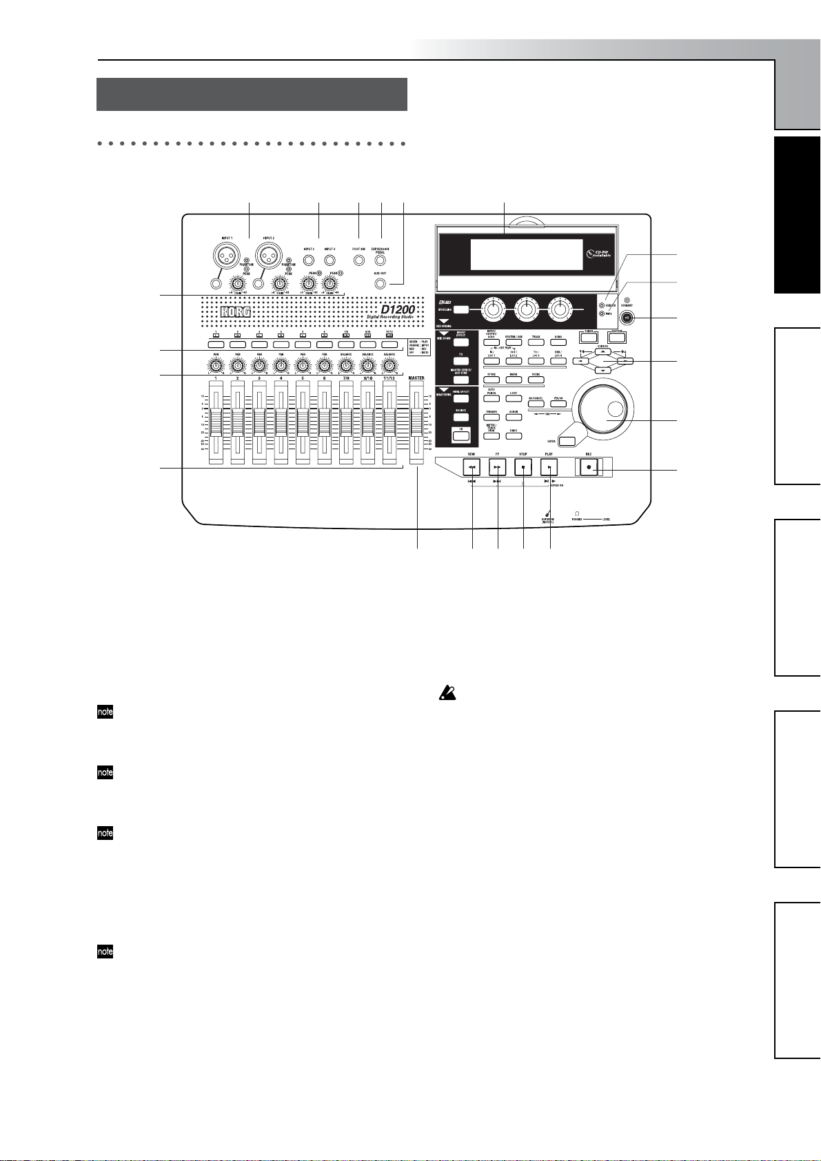
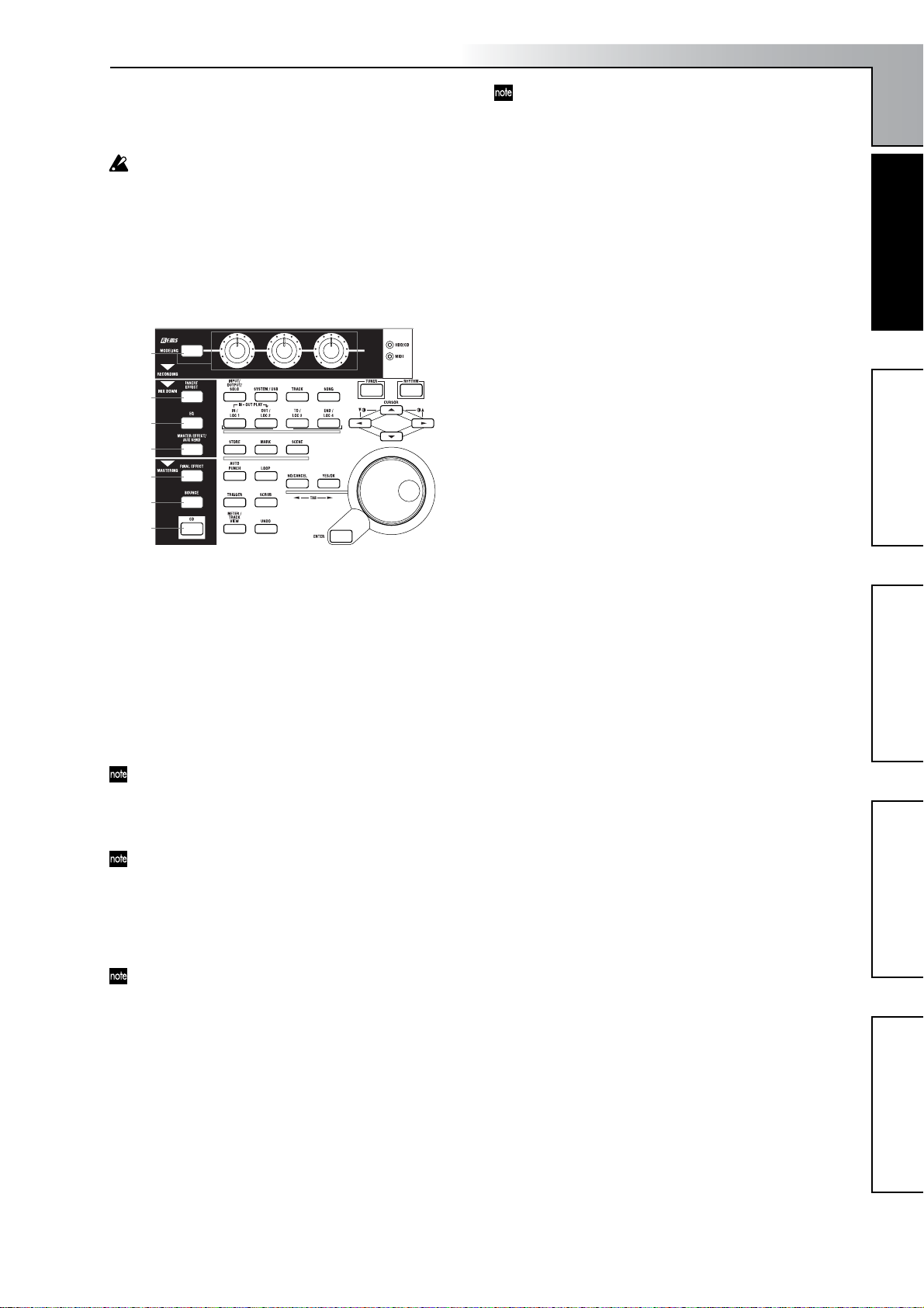
Top panel
3
7
8
9
1
2 4 5 6 21
20
Parts and their functionObjects in the display and
Parts and their function
19
18
17
16
their function
15
1 [INPUT 1], [INPUT 2] jacks
Use these jacks to input mic/line signals (such as from a
keyboard).
You can use either XLR jacks or TRS phone jacks, and
both sets of jacks are balanced.
Unbalanced phone plugs can also be connected.
The XLR jacks can supply +48 V phantom power to condenser mics.
If you connect a plug to the phone jack, no signal can be
input from the corresponding XLR jack. If you want to
use the XLR jack, disconnect any plug from the corresponding phone jack.
If you connect a plug to the [GUITAR IN] jack, no signal
can be input from the [INPUT 1] jack. If you want to input a signal from the [INPUT 1] jack, disconnect any
plug from the [GUITAR IN] jack.
These TRS phone jacks do not individually allow stereo
input.
2 [INPUT 3], [INPUT 4] jacks
Use these jacks to input mic/line signals (such as from a
keyboard).
These are balanced TRS phone jacks. Unbalanced phone
plugs can also be connected.
These TRS phone jacks do not individually allow stereo
input.
3 [TRIM] knob: –60...–10....+4 dBu
These knobs adjust the input level. Input level calibration marks are printed on the panel. Adjust the [TRIM]
knobs so that the peak indicators (the LEDs near each
knob) light when the input level of the connected instrument or device is loudest.
10 11 12 13 14
Although the input level will depend on the device or
performance, here are some guidelines for setting these
knobs.
–60 – –40 dBu: mic input
–30 dBu: guitar or bass guitar
–10 dBu: CD player or other consumer audio device
+4 dBu: keyboard or studio equipment
If nothing is connected, you may hear hum or noise
when you raise the [TRIM] knobs.
4 [FOOT SW] jack
A foot switch connected to this jack can be used to operate basic recorder functions when your hands are occupied by playing an instrument.
You can use a foot switch to control play/stop, to start/
stop manual punch-recording, to register a mark, or to
record tap tempo. (
Connect a PS-1 foot switch (sold separately) to this jack.
5 [EXPRESSION PEDAL] jack
A pedal connected to this jack can be used to control a
specified parameter of an insert effect. This lets you control an effect in realtime while you perform or record.
→
p.44)
(
Connect an EXP-2 or XVP-10 expression pedal (sold separately) to this jack.
6 [AUX OUT] jack
This outputs the external send audio signal from each
mixer channel. (The send amount is adjusted in the
[MASTER EFFECT/AUX SEND] “AuxSnd” tab page.)
Connect this jack to an external effect processor.
This is a phone jack.
→
Basic operationPreparationsListening to the demo song
p.101)
7
Page 10

7 [TRACK STATUS] keys
These keys are used to switch each track between play/
record or mute states. The status of the track will alternate each time you press the key.
PLAY (LED lit green): The track can be played.
REC (LED lit red): The track can be recorded. When
recording from the analog/digital inputs, you can select
up to four tracks for recording (two tracks in Modeling
mode).
INPUT (LED lit orange): The track can receive an exter-
nal audio signal. This state can be selected only while
stopped.
Select this when you want to perform while listening to
other tracks so that you can rehearse before recording,
or if you want to mix an external input source with the
playback.
MUTE (LED dark): The track is muted (silent).
The states that can be selected will depend on the state
and settings of the recorder.
PLAY
While stopped:
PLAY
While recording or playing: PLAY ↔ MUTE, INPUT ↔
MUTE
Modeling mode: PLAY → REC → MUTE → PLAY
These settings can be paired, or registered in a scene.
→ INPUT → REC → MUTE →
8[PAN] knobs (Ch1...6), [BALANCE] knobs (Ch7...12)
For each channel, these knobs adjust the position (pan)
or left/right balance of the stereo signal to the master
LR bus (→p.37).
For channels 1–6 for which pairing is “Off,” these knobs
control panning to the master LR bus.
For channels 1–6 for which pairing is “On” and for
channels 7–12, these knobs control the left/right balance
of the stereo signal to the master LR bus.
These settings can be paired, or registered in a scene.
When recording to channels that have a balance setting,
you must set the knob to “CNT.”
9 [CHANNEL] faders (Ch1...6, Ch7/8...11/12)
These faders adjust the recording/playback volume of
each channel (→p.37).
Channels 7–12 are stereo faders.
These settings can be paired, or registered in a scene.
• For channels whose [TRACK STATUS] is PLAY, the
fader adjusts the playback volume.
• For channels whose [TRACK STATUS] is REC, the
fader adjusts the recording level of the external audio
source or the rhythm.
• For channels whose [TRACK STATUS] is INPUT, the
fader adjusts the recording level of the external audio
source.
Faders that adjust the recording level will function differently depending on whether an external input is being recorded or bounce recording is being performed.
• When recording an external input (i.e., when the
[BOUNCE] “RecMode” tab page “Select RecMode”
parameter is set to “Input”), the channel fader
adjusts the recording level.
10 [MASTER] fader
This fader adjusts the overall volume of all channels.
The volume adjusted by this fader is output from the
[MASTER OUT L/R] jacks and the [S/P DIF OUT] jack.
• When recording an external input (i.e., when the
[BOUNCE] “RecMode” tab page “Select RecMode”
parameter is set to “Input”), the master fader adjusts
the volume level of the master LR bus.
• When bounce-recording (i.e., when the [BOUNCE]
“RecMode” tab page “Select RecMode” parameter is
set to “Bounce”), the master fader adjusts the recording level to the track(s) whose [TRACK STATUS] is
REC.
11 [REW] key
This key changes the location to an earlier time (rewind)
while stopped or moving.
If you hold down the [STOP] key and press the [REW]
key, you will move to the previous-numbered song (if
you are already at the beginning of the song) or to the
beginning of the current song (if you are in the middle
of the song).
12 [FF] key
This key changes the location to a later time (fast-forward) while stopped or playing.
If you hold down the [STOP] key and press this key, you
will move to the end of the current song (if not already
at the end) or to the beginning of the next song (if you
are already at the end of the current song).
If the Scrub function is on, you can press this key to per-
form Slow Play (→p.34).
13 [STOP] key
This key stops recording or playback, halting the
recorder.
14 [PLAY] key
This key plays tracks whose [TRACK STATUS] is PLAY.
For tracks whose [TRACK STATUS] is REC, pressing the
[REC] key and then this key will begin recording.
The LED of this key will light while the recorder is
recording or playing.
If the Scrub function is on, pressing this key will perform Play From, and pressing this key while holding
down the [STOP] key will perform Play To. (→p.34)
15 [REC] key
Press this key to enter record-ready mode (the LED will
blink). In order to enter record-ready mode, one or more
tracks must be set to a [TRACK STATUS] of REC. When
you press the [PLAY] key, the LED will light and recording will begin.
If the foot switch function (→p.101) is set to “PunchIn
Out”, the foot switch will perform the same function as
the [REC] key.
16 [VALUE] dial
Use this dial to edit values or to move the current location.
If the Scrub function is on, turning this dial will play the
track at the corresponding speed.
17 [CURSOR] keys
These keys move the cursor. They are also used to adjust
the contrast (brightness) of the display.
18 [POWER] key
This key turns the power on/off. (→p.15)
19 MIDI indicator
This indicator will light when a MIDI message is
received at the MIDI IN connector.
8
Page 11
Introduction
20 HDD/CD access indicator
This indicator will light when the hard disk is being
accessed during recording, playback, or editing, or if an
installed CD-R/RW drive is operating.
Never subject the D1200 to vibration or shock while this
HDD/CD access indicator is lit.
21 Display
This shows various information such as the volume
(level meters) during recording or playback, the time
(locate), and parameter settings. (→p.13)
You can adjust the angle of the display for best visibility.
22
33
23
24
25
26
27
28
29
30 31
36 37
39 40
41 42
43 44
32
35
38
45
46
34
22 [MODELING] key, [MODELING] knobs
This key lets you use effects for guitar, bass, and mic as
easily as if you were actually using dedicated hardware
devices. The effects are controlled by the three knobs
located below the display. Since there is no need to make
complicated preparations for recording, you can easily
apply an effect and record. (→p.45, 84)
23 [INSERT EFFECT] key
This key selects the location at which an insert effect is
inserted, selects the effect type, and select and edits
effect programs. (→p.42, 85)
These settings can be registered in a scene.
24 [EQ] key
Use this key to adjust the EQ (for track playback) of each
channel. (→p.37, 88)
These settings can be paired, and registered in a scene.
25 [MASTER EFFECT/AUX SEND] key
Use this key to select and edit effect programs for master
effects 1 and 2, and to set the send level from each channel to the master effects. This key is also used to set the
send level to an external effect. (→p.45, 89)
These settings can be registered in a scene. Send settings
can also be paired.
26 [FINAL EFFECT] key
Use this key to select and edit effect programs for the
final effect. (→p.43, 91)
27 [BOUNCE] key
Use this key to make recorder settings such as selecting
the recording source and the bounce-record method.
(→p.64, 92)
28 [CD] key
Use this key to create an audio CD. (→p.65, 93)
In order to use this key, the CDRW-1 CD-R/RW drive
option (sold separately) must be installed. (→p.149)
29 [INPUT/OUTPUT/SOLO] key
Use this key to select the mixer channel to which the
audio signal from each input jack will be input. (→p.98)
This key is also used to adjust the EQ applied to the analog inputs (for recording).
It is also used to solo channels, send, and returns. When
solo is on, the LED will blink.
Additionally, this key lets you select the audio signal for
monitor output, and specify the phase of each channel.
30 [SYSTEM/USB] key
This key lets you make various settings for the foot
switch and MIDI, to manage the disk, and to perform
backup and restore your data. (→p.101)
You can also connect your computer to the D1200 via
the USB connector, and exchange data between your
computer and the USB drive of the D1200.
31 [TRACK] key
Use this key to select the virtual track for each track, to
perform track editing operations such as copy or delete,
and to import or export a WAV file. (→p.108)
32 [SONG] key
Use this key to create a new song, rename or select a
song, perform song edit operations such as copy or
move, and to perform program-playback of songs.
(→p.116)
33 [TUNER] key
Press this key when you want to use the tuner. (→p.36,
95)
34 [RHYTHM] key
Use this key to switch the internal rhythm pattern playback on/off, set the song tempo, and create tempo
maps. The key will light if the rhythm is on. (→p.48, 95)
35 [IN/LOC1] key, [OUT/LOC2] key, [TO/LOC3] key,
[END/LOC4] key
Use these keys to register a desired location within the
song, or to instantly recall a registered location.
The locations registered here will be used as the punchin/out points, and as the locations for track editing
operations such as copy or delete. (→p.33, 118)
By holding down the [IN/LOC1] key and pressing the
[OUT/LOC2] key, you can listen to the audio between
the IN-OUT points.
36 [STORE] key
Press this key to register a location for a locate point,
mark, or scene.
The location at which you pressed the [STORE] key will
be preserved, and you can then press a desired key to
specify the memory in which this location will be stored.
To discard the location that was preserved, press the
[STORE] key once again instead of pressing a locate
memory key.
For details on these functions and on how to register a
location, refer to Locate (→p.32), Mark (→p.39), or Scene
(→p.39).
37 [MARK] key
Use this key to register a desired location within the
song as a Mark, or to jump instantly to a previously-registered mark.
Parts and their functionObjects in the display and
Parts and their function
their function
Basic operationPreparationsListening to the demo song
9
Page 12
This key is also used to edit the marks you have registered, for example by renaming or deleting them.
(→p.33, 119)
When you create an audio CD using the Disc At Once
method, these markers are used to separate the tracks.
(→p.66)
38 [SCENE] key
Use this key to register settings such as [CHANNEL]
faders, [PAN]/[BALANCE] knobs, EQ, and effect send
as a “scene” at the desired time within the song. If Scene
Read is turned on when you play back, the registered
scene will be selected automatically. You can also use
this key to perform scene editing operations such as
sort, rename, or delete (→p.39, 120). This key will light if
Scene Read is on.
39 [AUTO PUNCH] key
Use this key to turn the auto punch-in/out function on/
off, to make pre/post-roll settings, and to check the
start/end locations. (→p.54, 122)
This key will light if Auto Punch-in/out is on.
40 [LOOP] key
Use this key to switch looping on/off for recording or
playback, and to check the start/end locations. (→p.123)
This key will light if Loop is turned on.
41 [TRIGGER] key
Use this key to switch Trigger Recording on/off, allowing you to automatically start recording when an input
signal occurs. This key also lets you set the threshold
level and pre-trigger time. (→p.54, 123)
This key will light if the Trigger Recording function is
on.
42 [SCRUB] key
Use this key to switch the Scrub, Play To/From, or Slow
Play functions on/off. You can use these different functions by controlling the [VALUE] dial and TRANSPORT
keys. (→p.124)
43 [METER/TRACK VIEW] key
Use this key to view volume data during recording or
playback (level meters), and audio event data (track
view) for each track. (→p.125)
44 [UNDO] key
After you have recorded on a track or performed an
editing operation, you can use this key to perform Undo
(which returns the data to its prior state) or to perform
Redo (which cancels the Undo and returns the data to
the recorded or edited state).
You can use this to cancel or recall as many as 99 previous recording or editing operations. You can select
either 1, 8, or 99 times as the number of operations that
will be allowed for the Undo function. (→p.126)
This key will light if Undo or Redo is available.
45 [NO/CANCEL] key, [YES/OK] key
Use these keys as the “Yes”/“OK” or “No”/”CANCEL”
buttons that appear in the display. In addition, the [NO/
CANCEL] key moves back to the previous tab page, and
the [YES/OK] key proceeds to the next tab page.
46 [ENTER] key
Use this key to finalize a parameter setting or on/off setting.
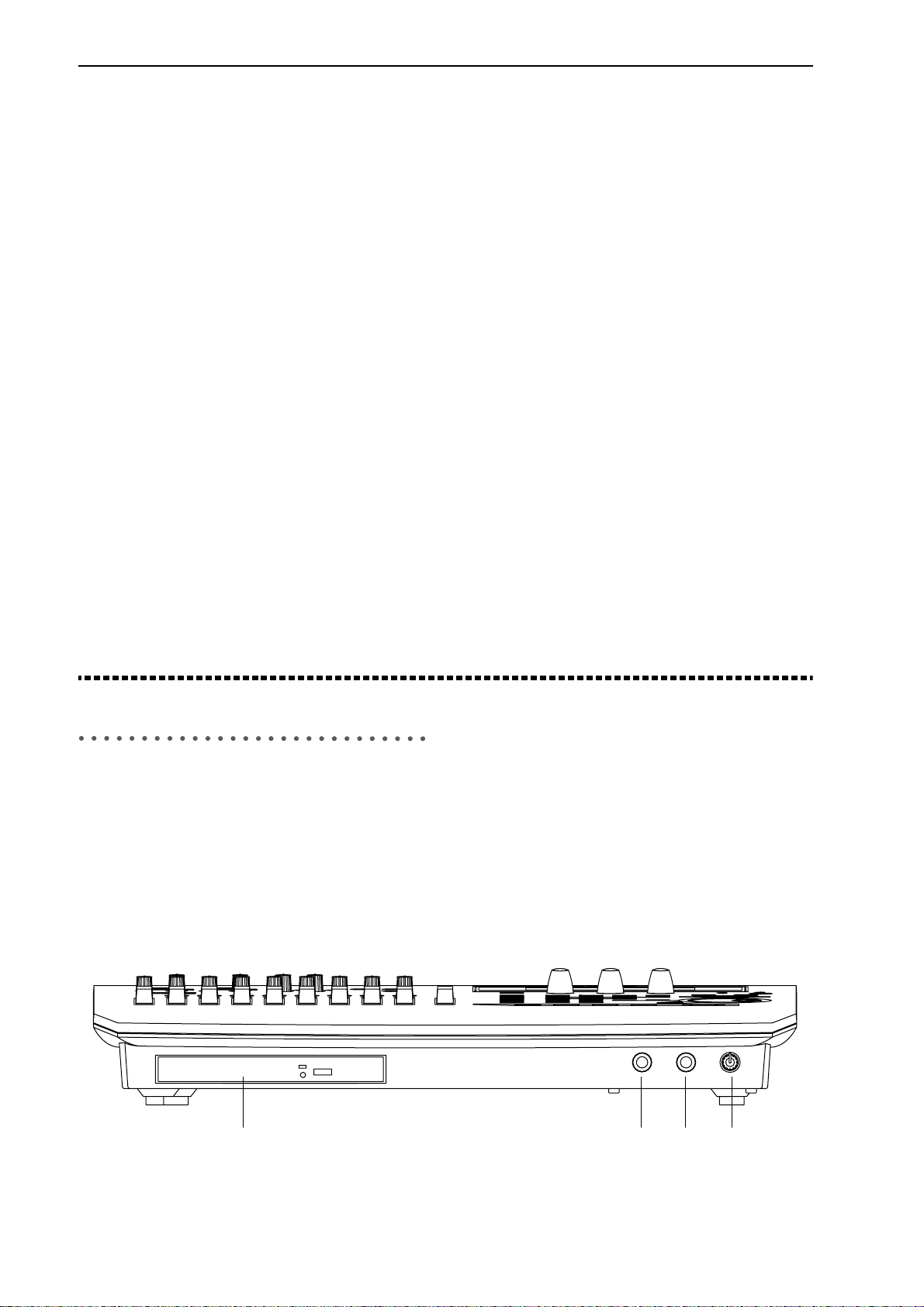
Front panel
1 CDRW-1 drive bay
The CDRW-1 CD-R/RW drive option (sold separately)
can be installed in this bay. (→p.149)
2 [GUITAR IN] jack
You can connect a guitar or bass guitar to this jack.
This is an unbalanced phone input jack with an imped-
ance of 1 MΩ.
1 2 3 4
3 [PHONES] jack
You can connect a set of headphones to this jack.
This is a stereo phone jack.
It outputs the same signal as [MONITOR OUT L/R].
4 [PHONES LEVEL] knob: 0...10
This knob adjusts the volume level of the headphones.
Larger markings indicate a higher volume.
10
Page 13
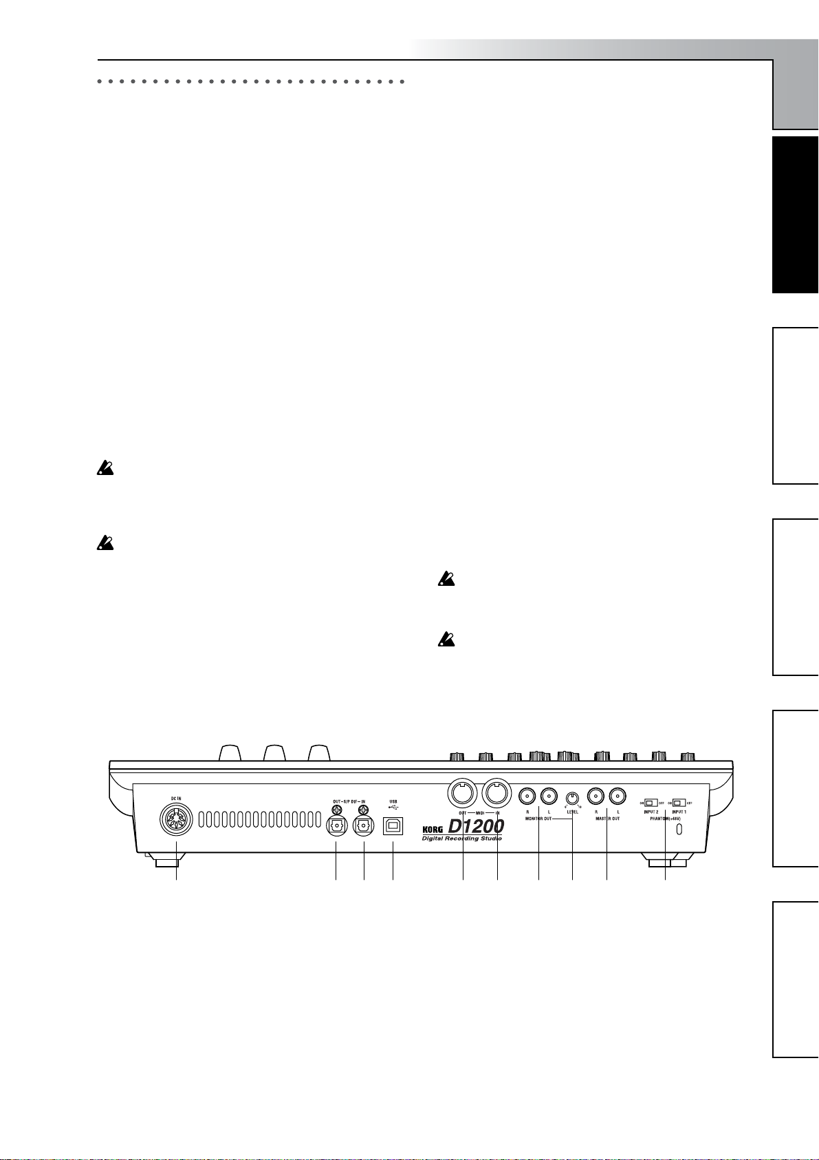
Rear panel
1 [DC IN] connector
Connect the included AC/DC power supply to this connector.
2 [S/P DIF OUT] jack
This is an optical S/P DIF format (IEC60958, EIAJ CP-
1201) digital output jack (stereo).
You can use an optical cable to connect it to the optical
digital input jack of a DAT or MD.
The same audio signal as the [MASTER OUT L/R] jacks
is digitally output from this jack at a sampling rate of
44.1 kHz.
3 [S/P DIF IN] jack
This is an optical S/P DIF format (IEC60958, EIAJ CP-
1201) digital input jack (stereo).
You can use an optical cable to connect it to the optical
digital output jack of a DAT or MD. Use a digital cable
that is no longer than 5 meters.
This jack contains a built-in sampling rate converter. If
the source connected here has a sampling rate of 48 kHz
or 32 kHz, it will automatically be converted to 44.1
kHz.
96 kHz is not supported.
4 [USB] connector
You can use a USB cable to connect this to your computer.
It is not possible to connect USB peripheral devices
(such as an external hard disk or CD-R/RW drive) to the
D1200.
5 [MIDI OUT] connector
This connector transmits MIDI data. Use it when you
want to control a connected external MIDI device from
the D1200. (→p.79)
Introduction
6 [MIDI IN] connector
This connector receives MIDI data. Use it when you
want to control the D1200 from a connected external
MIDI device. (→p.79)
7 [MONITOR OUT L/R] jacks
Connect your external monitor system to these jacks.
You can select the bus for monitor output in the
[INPUT/OUTPUT/SOLO] “Monitor” tab page
(→p.100). These jacks output the same signal as the
[PHONES] jack. These are RCA phono jacks.
8 [MONITOR OUT LEVEL] knob
This knob adjusts the volume that is output from the
[MONITOR OUT L/R] jacks.
9 [MASTER OUT L/R] jacks
These are analog audio outputs for the master LR bus
signal that combines the signals of each mixer channel
into a two-channel mix, or the audio signal that is
selected for soloing. To select a solo signal, make settings in the [INPUT/OUTPUT/SOLO] “Solo” tab page.
Connect these jacks to your external monitor system or
recording device. They output the same audio signal as
the [S/P DIF OUT] jack.
These are RCA phono jacks.
10 [Phantom power] switch
+48 V phantom power is supplied to the [INPUT 1, 2]
jacks, allowing you to use condenser mics. Phantom
power is supplied to the balanced XLR jacks, and can be
switched on/off independently for each channel. Turn
on this switch only for channels that are using a condenser mic.
You may damage your equipment if you connect or disconnect a condenser mic while phantom power is
turned on. Always turn phantom power off before you
connect or disconnect a condenser mic.
Never connect an dynamic type, other type mic or device if phantom power is turned on. Doing so may damage your equipment.
Parts and their functionObjects in the display and
Parts and their function
their function
Basic operationPreparationsListening to the demo song
1 2 3 4 5 6 7 8 9 10
11
Page 14
Objects in the display and
their function
Objects in the display
To select an object shown in the display, use the [CURSOR]
keys to select it, and press the [ENTER] key.
In this manual, references enclosed in double quotation
marks such as “...”, “...” button, or “...” tab refer to objects in the display. On the other hand, references enclosed in square brackets such as [...] key, [...] knob, [...]
dial, or [...] fader refer to controls or items on the front
panel or rear panel of the D1200.
g: Radio buttons f: Dialog box
f: Dialog box
Press the [YES/OK] key to execute, or the [NO/CANCEL] key to close the dialog box without executing.
You can also make your choice by selecting the “OK” or
“Cancel” button, and pressing the [ENTER] key.
a:Current
parameter
e: Tab page
c: Popup
button
b: Edit cell
d:Toggle
a: Current parameter
This is the name of the parameter that is currently
selected by the cursor.
In the case of icon-type parameters such as EQ or faders,
the value is shown at the right.
b: Edit cell
This is a parameter that is underlined in the display.
When you use the cursor to select an edit cell, the
parameter value display will be highlighted, and can be
edited.
To edit the parameter value in the edit cell, use the
[VALUE] dial (→p.8) or popup buttons in the display.
c: Popup button
When you select one of these buttons and press the
[ENTER] key, a dialog box (f) will appear.
To input a parameter value, select the desired value in
the dialog box.
, ,
button
g: Radio buttons
This type of button is used to select one of multiple
choices. Select one of the radio buttons and press the
[ENTER] key.
h: Icons
h: Icons
These are objects shaped like sliders or knobs. To edit
the value, select the icon and turn the [VALUE] dial.
i: Scroll buttons
i: Scroll buttons
Use these to see parameters that are not currently shown
in the display.
d: Toggle button
e: Tab page
12
This type of button will switch a function on/off each
time you select it and press the [ENTER] key. The frame
will become thicker when selected.
(on)/ (off)
Each mode contains numerous parameters, which are
organized into pages. These pages are divided by tabs.
Page 15
Basic operation
1. Selecting a mode
The various function of the D1200 are organized under different modes. To access a specific feature, select the mode
that contains the desired function by pressing its key.
For details on the functions within each mode, refer to “Ref-
erence” (→p.83).
2. Selecting a tab page
Each mode contains numerous parameters, which are organized into pages. These pages are divided by tabs.
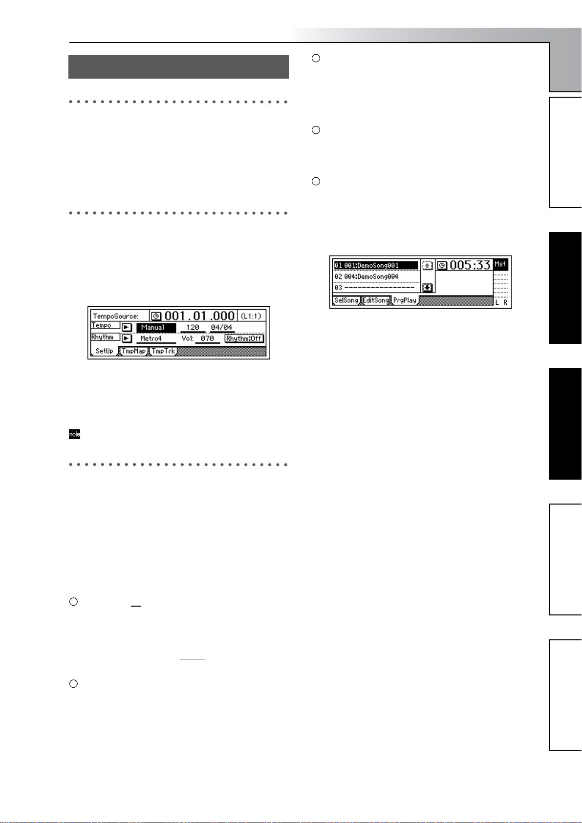
1 Press the key of the desired mode.
The following screen shows a page in RHYTHM mode
which will appear when you press the [RHYTHM] key.
Introduction
Toggle buttons
These are used to switch functions or on/off settings
(→p.12).
• Use the [CURSOR] keys to select the parameter, and
press the [ENTER] key. The setting will be switched
on/off each time you press the key.
Radio buttons
These are used to select one of multiple choices.
• Use the [CURSOR] keys to move the cursor to the
desired selection, and press the [ENTER] key.
Selecting one item from a list
•To select a song or mark, turn the [VALUE] dial select
the desired item.
•To select a song in the program playback list, use the
following procedure.
1 Select the playback list number.
Parts and their functionObjects in the display and
their function
their function
2 Select the desired tab page.
Use the [YES/OK] and [NO/CANCEL] keys to select
the tab page.
You can also step through the tab pages by repeatedly
pressing the key of the currently selected mode.
Some pages contain only one tab.
3. Selecting and editing a parameter
Selecting a parameter
To edit a parameter, use the [CURSOR] keys to select the
parameter you want to edit.
In a list display, turn the [VALUE] dial to move the cursor.
Editing a parameter value
The way in which you edit or set a parameter value will
depend on the type of parameter.
Underlined “ ” parameters, or icons such as EQ
Use the [CURSOR] keys to move the cursor to the
parameter, highlighting it. Then turn the [VALUE] dial
to specify the value.
This is the typical method, and also applies to underlined parameters such as “T
EQ that are indicated by icons, and locate times.
empo,” parameters such as
2 Turn the [VALUE] dial to select a song.
Objects in the display and
Basic operationPreparationsListening to the demo song
Basic operation
Popup buttons and dialog boxes
Use the popup button to open the dialog box, and spec-
ify the parameter value (→p.12)
• Use the [CURSOR] keys to move the cursor to the
popup button, and press the ENTER button to open
the dialog box.
13
Page 16
Preparations
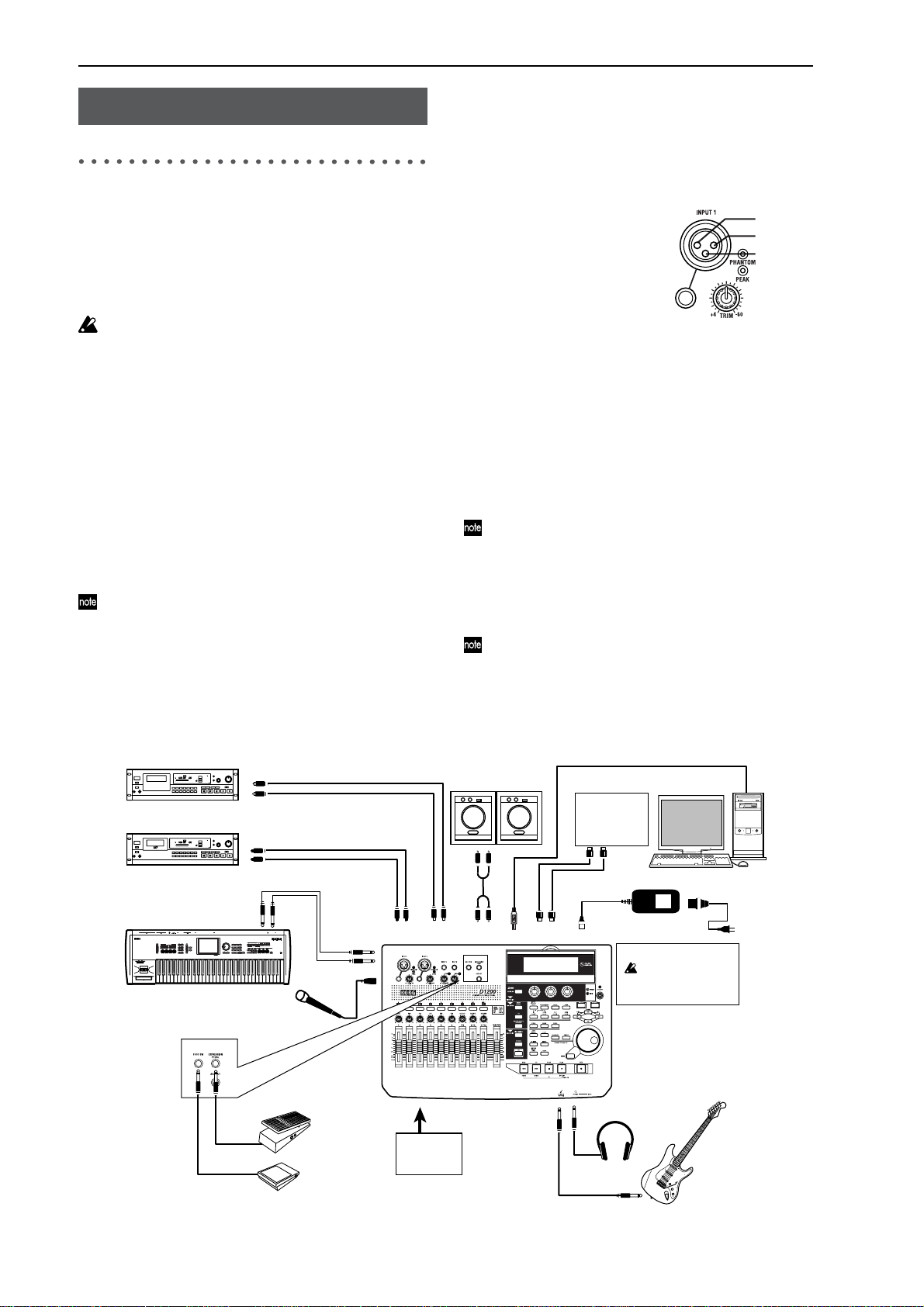
1. Connections
Here are some examples of basic connections for recording
with the D1200. As necessary, substitute the equipment you
are using for the devices named here.
CDRW-1 connections
For details on installing the CDRW-1 CD-R/RW drive
option, refer to p.149.
You must make all connections with the power turned
off. Making connections with the power turned on may
damage your speaker system or cause malfunctions.
1-1. Output (audio output) connections
In order to hear the sounds recorded on the D1200, you will
need to connect it to a monitor speakers (speakers with an internal amp) or other audio equipment, or use headphones.
Connecting audio equipment for monitoring
• Use RCA phono cables to connect monitor speakers
to the [MONITOR OUT L/R] jacks.
• If you will use headphones for monitoring, connect
your headphones (with a phone plug) to the
[PHONES] jack. Use the [PHONES LEVEL] knob to
adjust the volume.
The audio signal that is output from the [MONITOR
OUT L/R] jacks and the [PHONES] jack can be selected
in the [INPUT/OUTPUT/SOLO] “Monitor” tab page.
(→p.100)
1-2. Input (audio input) connections
The D1200 has four channels of analog input and one (twochannel) digital input jack.
Connecting a guitar
• Guitar or bass guitar ↔ [GUITAR IN] jack
Connecting a mic
• Mic (XLR) ↔ [INPUT 1],
[INPUT 2], phantom power
Connecting a keyboard
• Synthesizer etc. ↔ [INPUT
1]–[INPUT 4] jacks
Connecting audio devices
• Sub input
For details on how to specify the mixer channel to
which the input audio will be sent, and how to audition the input signal, refer to p.22.
•A guitar or bass guitar routed through a compact
effects device can be connected to the [INPUT 1]–
[INPUT 4] jacks.
• If you want to use a stereo input, select two adjacent
inputs (1–2 or 3–4) so that you can perform track
editing more efficiently.
If you are recording from a mic, place the mic sufficiently far from the D1200 so that it does not pick up noise.
Connections for digital recording
• Digital output jack of a DAT or MD with an optical
digital (S/P DIF) output ↔ [S/P DIF IN] of the
D1200 (use an optical digital cable for connections)
For details on how to specify the mixer channel to which
the input audio will be sent, and how to audition the input signal, refer to p.35.
2: HOT
1: GND
3: COLD
Master recorder (Analog: cassette tape recorder, etc.)
INPUT L/R
Master recorder (Digital: DAT, MD, etc.)
Keyboard
FOOT SWITCH
DIGITAL IN
DIGITAL OUT
OUTPUT
EXPRESSION
PEDAL
INPUT
1–4
Mic
EXP-2
Foot controller
PS-1
Pedal switch
S/P DIF
IN OUT
CDRW-1
CD-R/RW
Drive option
Monitor speakers etc.
MONITOR
MASTER
OUT L/R
OUT L/R
MIDI
IN/OUT
USB
GUITAR IN
MIDI
sequencer
MIDI
OUT/IN
DC IN
PHONES
Headphones
Computer
to the AC outlet
Power supply connection
You must use the
included AC/DC power
supply
Guitar
14
Page 17
1-3. Connections when using external record-
ing devices
Here are the connections for recording your song onto an external device (DAT, MD, tape recorder, etc.).
• Optical digital (S/P DIF) input jack of a DAT or MD
↔ [S/P DIF OUT] of the D1200 (use an optical digital
cable for connections)
• AUX IN jacks of a cassette tape recorder or other ana-
log recording device ↔ [MASTER OUT L/R] jacks of
the D1200
Introduction
2. Turning the power on/off
2-1. Connecting the power supply
1 Connect the included AC/DC power.
Connect the included power cable to the AC/DC power
supply.
2 Plug the power cable from the AC/DC power supply
into an AC outlet.
1-4. Connections when using an external effect
If you apply an external effect to the signal that is sent from
the [AUX OUT] jack, connect the return from the effect unit
to the [INPUT 1]–[INPUT 4] jacks.
You can select whether the effect will be returned to the
mixer channels in the same way as for conventional in-
puts, or sent directly to the master bus. (→p.45)
1-5. Pedal connections
Using a pedal switch to perform manual punch recording
or play/stop operations
Connect a pedal switch (separately sold option: PS-1) to
the [FOOT SWITCH] jack.
Using a foot pedal to control an effect
Connect an expression pedal (separately sold option:
EXP-2, XVP-10) to the [EXPRESSION PEDAL] jack.
A volume pedal will not function correctly even if connected.
1-6. MIDI connections
Controlling effects or switching scenes from an external
MIDI device
• MIDI OUT connector of the external MIDI device ↔
[MIDI IN] connector of the D1200 (→p.79)
Synchronizing the D1200 with a MIDI sequencer etc.
• MIDI IN connector of your sequencer ↔ [MIDI OUT]
connector of the D1200 (use a MIDI cable for connections)
• MIDI OUT connector of your sequencer ↔ [MIDI IN]
connector of the D1200 (→p.79)
1-7. USB connections
Save or backup data on your pc
•Your PC’s USB connector ↔ the D1200’s [USB] connector (use a USB cable for connections) (→p.77)
2-2. Turning the power on
Follow this procedure to turn on the power of the D1200 and
each connected device.
Before you turn on the power, be sure to set the volume
of each device to the minimum position, and turn on the
power switches starting with the “upstream” devices
that output the audio signal.
1 Lower the D1200’s [MASTER] fader to –∞.
Lower the volume on external devices to the minimum
position.
2 Turn on the power of external input devices, such as a
keyboard that sends an audio signal to the D1200.
3 Press the [POWER] switch of the D1200 to turn on the
power.
The display will show the opening message. Then the
[SONG] “SelSong” tab page will appear.
The song number that had been selected when you
turned off the power will be selected.
4 Turn on the power of external output devices such as
the monitor system to which the audio from the D1200
is being sent.
2-3. Turning the power off
Turn off the power when you are finished all operations
such as song playback and recording. Use the following procedure to turn off the power of the D1200 and of each connected device.
Never disconnect the AC/DC power supply until the
power has been turned completely off. Doing so may
cause data to be lost.
When turning the power off, set the volume of all devices to the minimum position, and turn off the power
switches starting with the “downstream” devices to
which the audio signal is being sent.
Audio that you record on the D1200 and mixer settings
etc. that you make are saved automatically when you select or change songs, or when you turn off the power.
However, effect settings you edit outside of Modeling
mode will be lost if you turn off the power without saving them.
1 If you want to keep the effect settings you edited out-
side of Modeling mode, save them (→p.43).
2 Lower the [MASTER] fader of the D1200 to –∞. Set the
volume of externally connected device to the minimum
position.
Parts and their functionObjects in the display and
their function
Basic operationPreparationsListening to the demo song
Preparations
15
Page 18
3 Turn off the power of devices such as a monitor system
or MD recorder to which the audio from the D1200 is
being sent.
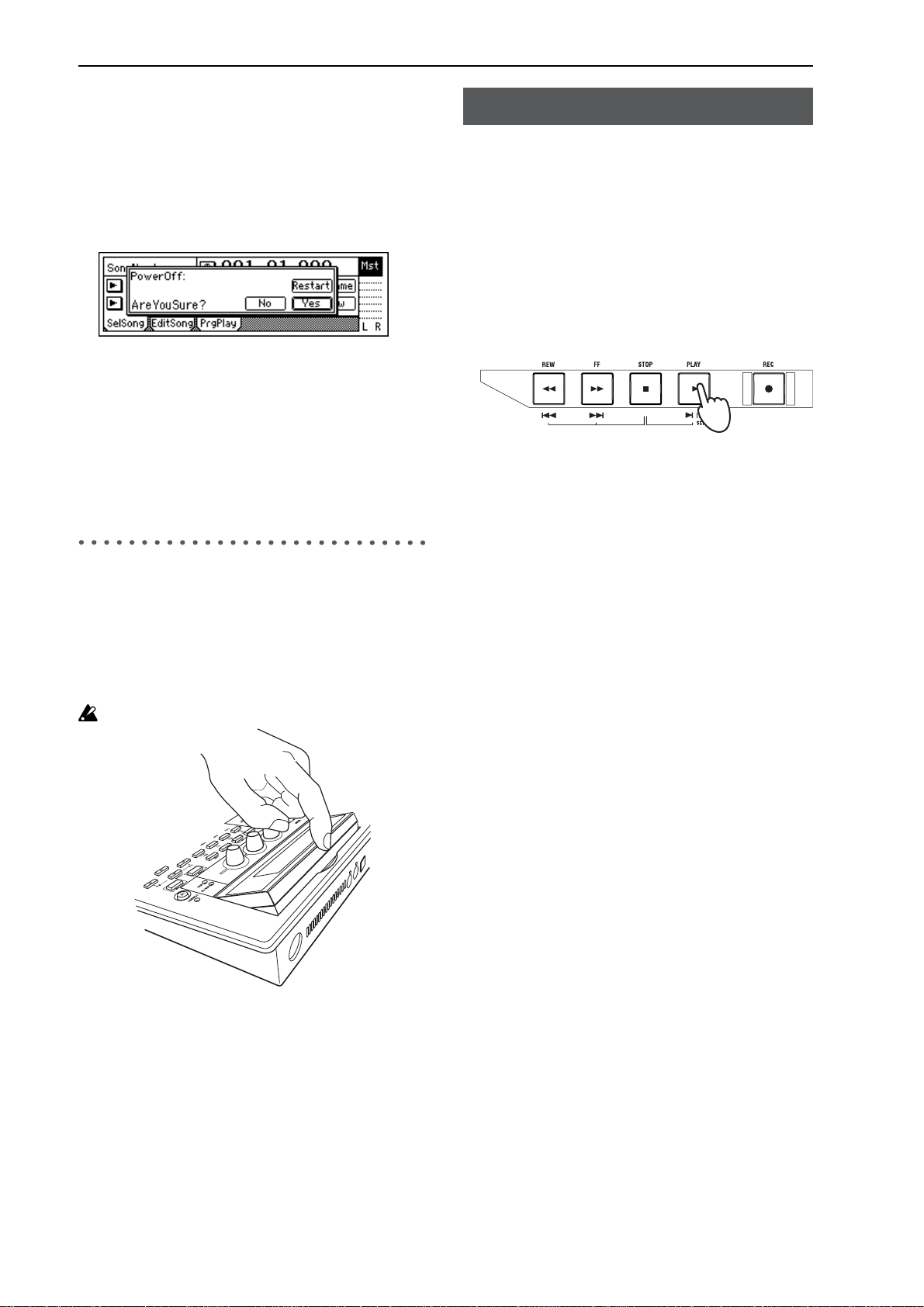
4 Press and hold the D1200’s [POWER] key until the
power-off confirmation dialog box appears.
If you press the [YES/OK] key, the song will be saved
automatically, and then the power will be turned off.
If you press the [NO/CANCEL] key, you will return to
the previous screen.
5 Turn off the power of external input devices such as
keyboards.
The Restart function
In the power-off confirmation dialog box, you can select
the “Restart” button and press the [ENTER] key to
restart the D1200.
This clears the Undo data in order to recover hard disk
capacity.
3. Display
Listening to the demo song
When the D1200 is shipped from the factory, it contains several demo songs.
Here’s how to listen to these demo songs.
1 Set the D1200’s [CHANNEL] faders to the 0 mark, and
the [MASTER] fader to –∞. Connect your headphones.
2 Turn on the power.
3 Select the song that you want to play.
4 Set the [TRACK STATUS] keys of all tracks so that the
LEDs are lit green.
If it is lit a different color, or is dark, press the key to
make it light green (PLAY).
5 Press the [PLAY] key to begin playback.
6 Slowly raise the [MASTER] fader to adjust the volume
level.
While the song plays, adjust the [CHANNEL] faders,
[PAN] knobs, and EQ, and change the program for the
insert effect, and master to hear the result.
7 When the demo song ends, press the [STOP] key to stop
playback.
3-1. Adjusting the angle
You can lift the upper part of the display to adjust the angle.
Adjust the angle for easiest viewing.
To adjust the angle
Raise the upper part of the display to adjust the angle.
Do not use excessive force to move this.
3-2. Adjusting the contrast
The readability of the screen will depend on the height of
your line of sight or the temperature, so adjust the contrast
as necessary.
Demo song list
The Game
Written and performed by Insex In Amber
Ted Burger — Guitars, Bass
Jack Bielata — Vocals
Steve Michael — Drums
© 2000 Ted Burger, Jack Bielata All Rights Reserved
www.insexinamber.com
Play The Blues
Written and performed by Nomura Daisuke.
© 2002 KORG Inc. — all rights reserved.
To adjust the contrast
A combination of [CURSOR] keys is used to adjust the
contrast.
UP+LEFT: Hold the CURSOR [UP] key and press the
[LEFT] key to make the characters lighter.
UP+RIGHT: Hold the CURSOR [UP] key and press the
[RIGHT] key to make the characters darker.
16
Page 19
Quick Start Tutorial
This Quick Start Tutorial is designed to familiarize you with many of the
features of the D1200, as well as with the many recording procedures that
can be performed using the D1200. While the Operation and Reference
sections of this manual will explain every feature and control in great detail, this step-by-step tutorial will allow you to “learn by doing” as we
take you through the entire process, from recording your first track to
mastering a CD.
Step 1: Quick recording
Connect your guitar, record your performance on tracks 1 and 2, and play
it back.
Step 2: Overdubbing
While listening to the guitar performance that you recorded in step 1,
connect a keyboard and record (overdub) your performance on tracks 9
and 10. Then record a vocal on track 3.
Step 3. Mixing
Apply effects to each track, and adjust the volume and EQ. Use the master effects to apply effects to the entire song while you mix.
Step 4. Mastering
Create a two-track master track from the song that you mixed-down in
Step 3. Write the master track to CD-R to create your own original CD.
Step 1: Quick recording
Step 2: OverdubbingStep 3. Mixing
Step 1: Quick recording
1. Getting ready
If you will be using the separately sold CDRW-1, refer to “About
the CDRW-1” (→p.149) and install the CDRW-1 before you con-
tinue with the steps below.
1 Connect your guitar.
Set the INPUT 1 [TRIM] knob to the minimum position, and connect
your guitar to the [GUITAR IN] jack.
2 Connect your headphones to the [PHONES] jack.
2. Turning on the power
1 Connect the AC/DC power supply.
Connect the included AC/DC power supply to the [DC IN] jack.
Connect the included power cable to the AC/DC power supply.
Connect the power cable to an electrical outlet.
2 Set the [MASTER] fader to the “–∞” position.
3 Press the [POWER] key to turn on the power.
Connection diagram (→p.14)
Turning the power on (→p.15)
Step 4. Mastering
17
Page 20
3. Creating a new song
In order to begin recording, you must first create a new blank song.
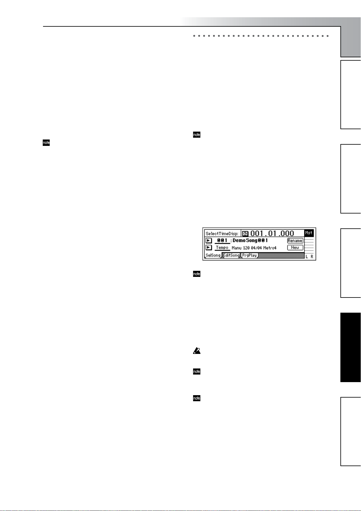
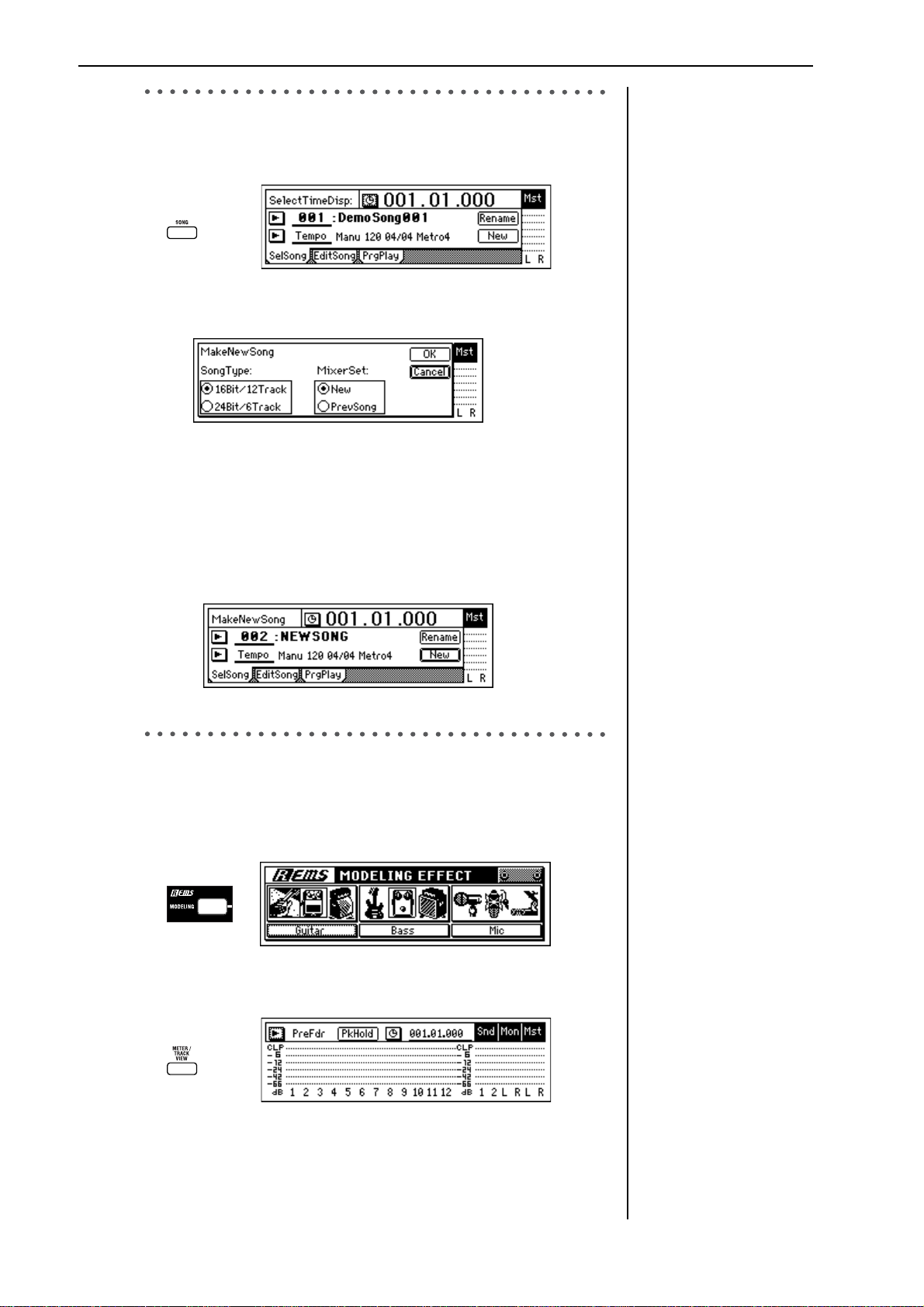
1 Press the [SONG] key to access the “SelSong” tab page.
2 Use the [CURSOR] keys to select the “New” button, and press the
[ENTER] key. The “MakeNewSong” dialog box will appear.
3 Specify the bit depth/number of tracks and the mixer settings for the
song that will be created.
Use the “SongType” buttons to select the bit depth and number of
tracks, and press the [ENTER] key. Select the “MixerSet” setting in
the same way.
For this example, select “16Bit/12Track” and “New.”
4 Press the [YES/OK] key.
A new empty song named “NEWSONG” will be created
“SongType,” “MixerSet”
(→p.116)
Editing the song name
(→p.31)
4. Using the modeling mode
1 Press the [MODELING] key, select “Guitar” from the three catego-
ries, and press the [ENTER] key.
The LEDs of the [MODELING] key and the CH 1 and 2 [TRACK
STATUS] keys will light red.
2 Check the input level.
Press the [METER/TRACK VIEW] key.
Modeling mode (→p.45)
18
Page 21
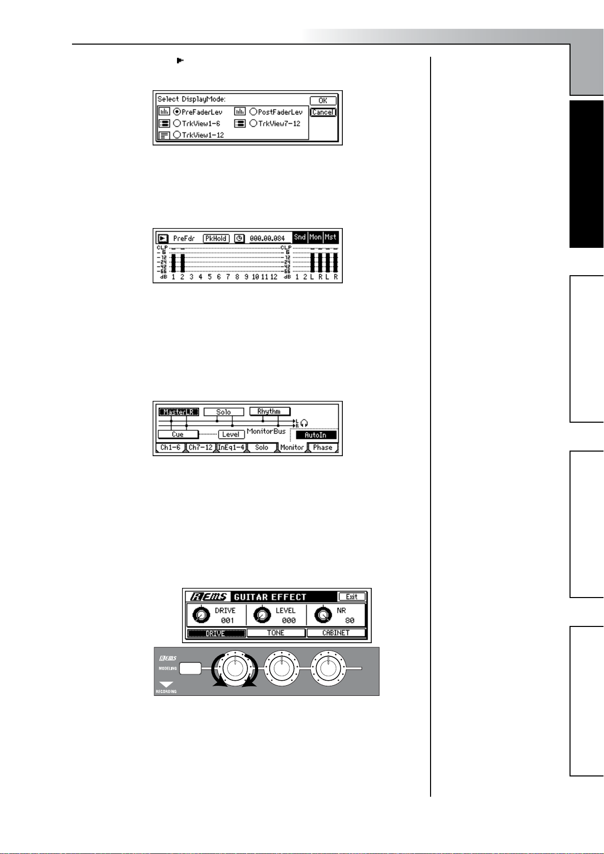
Select the “ ” button and press the [ENTER] key to open the dialog
box.
Select the “PreFaderLev” radio button, press the [ENTER] key, and
then press the [YES/OK] key.
3 As you play your guitar, watch the Ch1 and Ch2 meters and adjust
the INPUT 1 [TRIM] knob. You will not be hearing the guitar signal
at this point.
Adjust the level as high as possible without allowing the level
meter’s “CLP” indicator to light when you play most strongly.
In general, you should adjust the [TRIM] knob so that the peak indicator (the LED near the [TRIM] knob) lights when you play your
loudest passage.
4 Now, let’s listen to the audio signal.
Set the [CHANNEL 1] and [CHANNEL 2] faders to unity gain (0 dB).
Access the [INPUT/OUTPUT/SOLO] “Monitor” tab page.
Select the “MasterLR” button and press the [ENTER] key to turn it
“On” (highlighted). Slowly raise the [MASTER] fader, and make sure
that you hear the sound of your guitar from the headphones.
5 Dial up your settings for the modeling effects.
Return to the Modeling mode page either by pressing the [MODELING] key.
While you listen to the sound in your headphones or monitors, use
the three modeling knobs to adjust the “DRIVE,” “TONE,” and
“CABINET” settings to obtain the desired sound.
Quick Start Tutorial
Use the [PHONES LEVEL]
knob or the [MONITOR OUT
LEVEL] knob to adjust the
output volume.
To allow a stereo effect to be
heard in stereo, turn the
[PAN1] knob to the far left
and the [PAN2] knob to the
far right.
To tune your guitar (→p.36:
Using the tuner)
Step 1: Quick recordingStep 2: OverdubbingStep 3. Mixing
Step 1: Quick recording
Step 4. Mastering
19
Page 22
5. Setting up a rhythm
Here’s how to make rhythm settings so that you can listen to a rhythm
pattern while you record.
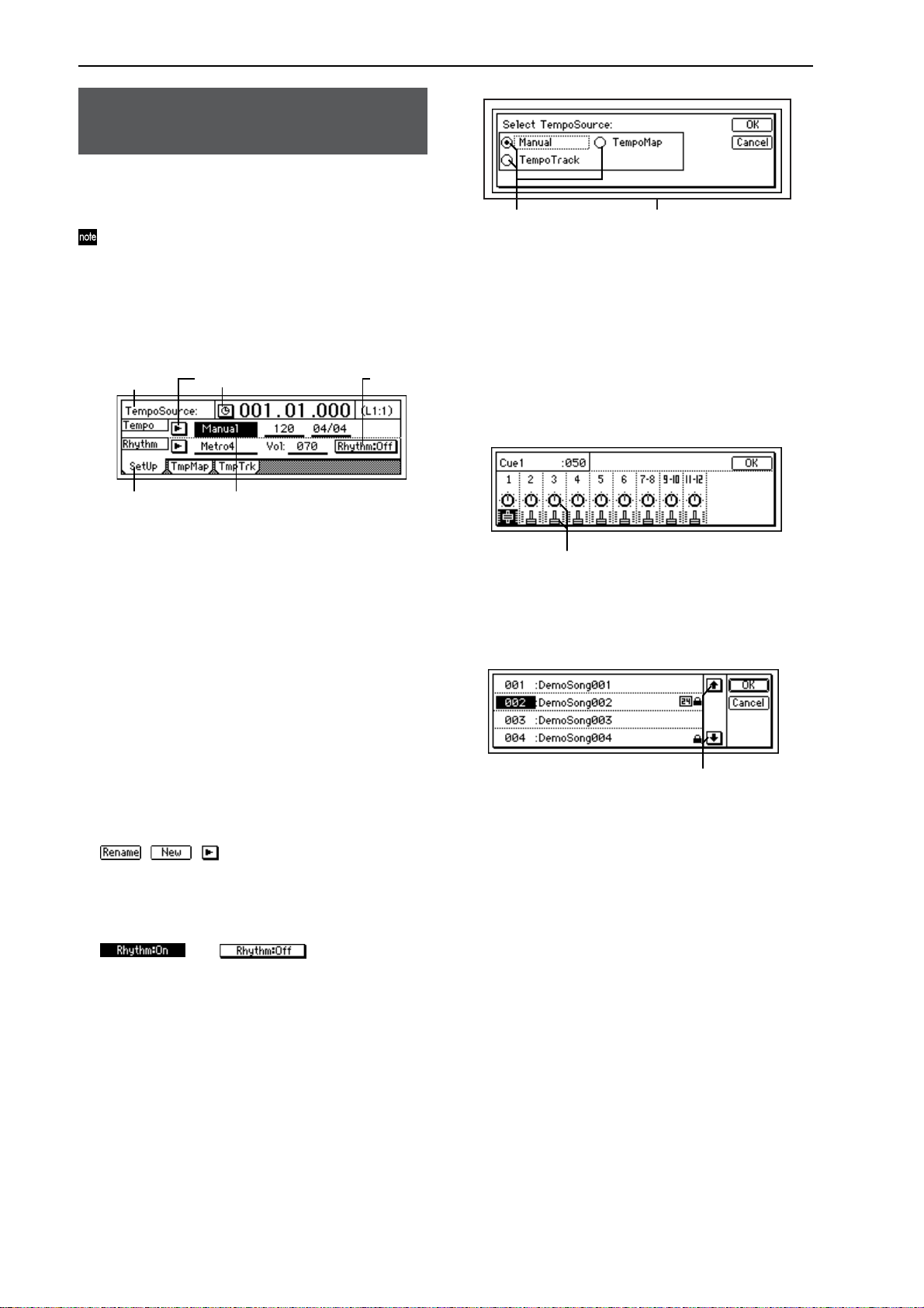
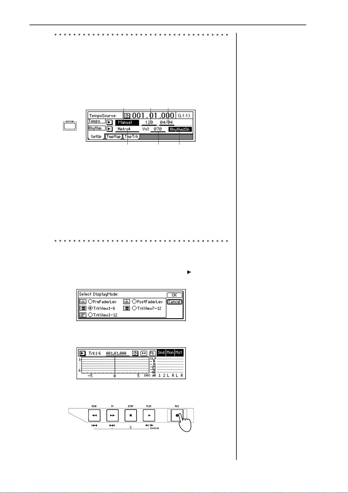
1 Press the [RHYTHM] key.
In the [RHYTHM] “Setup” tab page, turn the “Rhythm” button “On”
(highlighted).
The [RHYTHM] key will light. Raise the [MASTER] fader and you
will hear the rhythm.
TempoSource Tempo Beat
SelRhythm RhythmVol
2 Specify the tempo, time signature, and rhythm pattern.
Select “TempoSource,” and select the tempo source.
For this example, choose “Manual.” The same tempo, time signature,
and rhythm pattern will be used throughout the song.
Select “Tempo,” and turn the [VALUE] dial to adjust the tempo.
Select “Beat,” and turn the [VALUE] dial to specify the time signa-
ture.
Select “SelRhythm,” and turn the [VALUE] dial to select a rhythm
pattern.
Select “Vol,” and turn the [VALUE] dial to adjust the rhythm vol-
ume.
If you want the tempo, time
signature, and rhythm pattern
to change during the song,
you will need to create tempo
maps. (→p.49)
6. Recording
1 Access the track view screen so you can view the status of the record-
ing tracks.
Press the [METER/TRACK VIEW] key, select the “ ” button, and
press the [ENTER] key to open the dialog box.
In “SelectDisplayMode,” select the “TrkView1–6” radio button and
press the [ENTER] key. Then press the [YES/OK] key.
2 Press the [REC] key to enter record-ready mode.
The [REC] and [PLAY] LEDs will blink.
Trigger recording (→p.54)
Recording the rhythm
(→p.48)
20
Page 23
3 When you are ready to perform, press the [PLAY] key.
The [REC] and [PLAY] LEDs will light.
When recording starts, begin performing.
You will hear the rhythm pattern you selected. Go ahead and play
along.
4 When you have finished playing, press the [STOP] key.
Quick Start Tutorial
To stop the rhythm
In the [RHYTHM] “Setup”
top panel, select the
“Rhythm” button and press
the [ENTER] key to turn it
“Off.”
Step 1: Quick recordingStep 2: OverdubbingStep 3. Mixing
Step 1: Quick recording
Recording will stop, and the [REC] and [PLAY] LEDs will go dark.
In the track view screen, a heavy line will indicate the region that you
recorded.
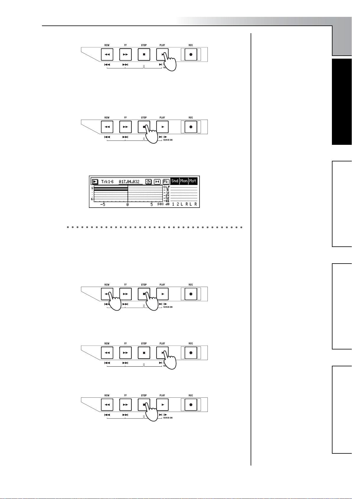
7. Play back
Now let’s play back the song you just recorded.
1 Press the track 1 and 2 [TRACK STATUS] keys to set them to PLAY
(LED lit green).
2 While holding down the [STOP] key, tap the [REW] key.
The counter display will move to the beginning of the song.
3 Press the [PLAY] key to begin playback.
During playback, the [PLAY] LED will light green. Use the [MASTER] fader to adjust the volume.
The heavy line will appear
even in sections where you
were not actually playing
your instrument.
Counter display, move to time
(→p.32)
4 Press the [STOP] key.
Playback will stop, and the [PLAY] LED will go dark.
To exit Modeling mode
(→p.47)
Step 4. Mastering
21
Page 24
Step 2: Overdubbing
1. Assigning inputs to the mixer
In this section, you’ll connect your keyboard to the [INPUT 3] and [INPUT 4] jacks, assign the signals to mixer channels 9 and 10, and record the
signal on tracks 9 and 10.
1 Set the INPUT 3 and INPUT 4 [TRIM] knobs to the minimum posi-
tion (+4 dB), lower the [MASTER] fader, and connect your keyboard
to the [INPUT 3] and [INPUT 4] jacks.
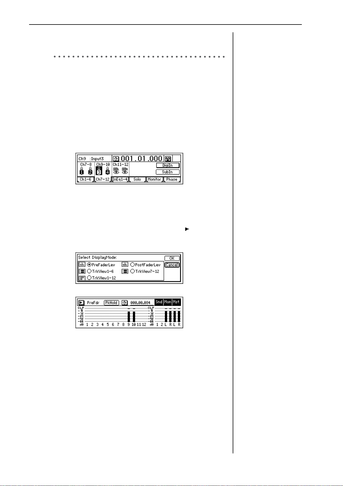
2 Specify the input channels.
Access the [INPUT/OUTPUT/SOLO] “Ch7–12” tab page. Select the
“Ch9” icon, and use the [VALUE] dial to select “INPUT 3.” In the
same way, select the “Ch10” icon and use the [VALUE] dial to select
“INPUT 4.”
Using these settings, the [INPUT 3] and [INPUT 4] jacks will be
assigned to mixer channels 9 and 10.
3 Press the track 9/10 [TRACK STATUS] key to select INPUT (LED lit
orange).
4 Use the [TRIM] knobs to adjust the input level.
Press the [METER/TRACK VIEW] key. Select the “ ” button and
press the [ENTER] key to open the dialog box. Select “PreFaderLev,”
and press the [YES/OK] key.
If you are using a stereo input
source, it will be easier to edit
track and effect settings if you
select adjacent inputs (1–2 or
3–4), and route them to adjacent mixer channels.
22
As you play the keyboard, watch the Ch9 and Ch10 levels and adjust
the INPUT 3 and 4 [TRIM] knobs.
Set the levels as high as possible without allowing the level meters to
reach “CLP” when you play the keyboard at your loudest level.
In general, you should adjust the [TRIM] knob so that the peak indicator (the LED near the [TRIM] knob) lights when the maximum
input level is reached.
5 Set the [CHANNEL 9–10] fader to unity gain (0 dB).
Use the [PHONES LEVEL]
knob or the [MONITOR OUT
LEVEL] knob to adjust the
output volume.
Page 25
Quick Start Tutorial
2. Applying an insert effect to the keyboard.
1 Access the [INSERT EFFECT] “InsAss” tab page.
2 Select the “Assign:” “ ”button and press the [ENTER] key to open
the dialog box. Select “Input(In)” and press the [YES/OK] key.
3 Select the “SelectEffType:” “ ”button and press the [ENTER] key.
Select the “2in2outx2” effect type (as shown in the screen in step 1)
and press the [YES/OK] key.
4 Now we need to insert the effect between INPUT 3 and channel 9,
and between INPUT 4 and channel 10.
Select the “InsertTo:” button and press the [ENTER] key.
In the display, you will see the two insert effects shown as boxes
labeled 1 and 2. The numbers to the left show which inputs are feeding the effect, the numbers to the right show to which channels the
effect is being output.
Highlight the number to the upper right of effect 1. Turn the
[VALUE] dial until the display shows In3 and In4 on the left and
(channels) 9 and 10 on the right and press the [YES/OK] key.
5 Select an effect program.
Access the [INSERT EFFECT] “InstEff1” tab page.
Select “EffectNumber,” and turn the [VALUE] dial to select an effect
program. When you have made your selection, press the [YES/OK]
key.
Step 1: Quick recordingStep 2: OverdubbingStep 3. Mixing
Step 2: Overdubbing
Effect Program List (→p.154)
3. Overdubbing
1 Select the playback tracks.
For each track that you want to play back, press the [TRACK STATUS] key to select PLAY (LED lit green). For this example, set tracks 1
and 2 to PLAY.
2 Select the recording tracks.
For each track that you want to record, press the [TRACK STATUS]
key to select REC (LED lit red). For this example, set tracks 9/10 to
REC.
3 Mute the tracks you are not using.
For each track that is not being played or recorded, press the [TRACK
STATUS] key to select MUTE (LED dark), so that you will not hear
tracks that are not being recorded or played.
Step 4. Mastering
23
Page 26
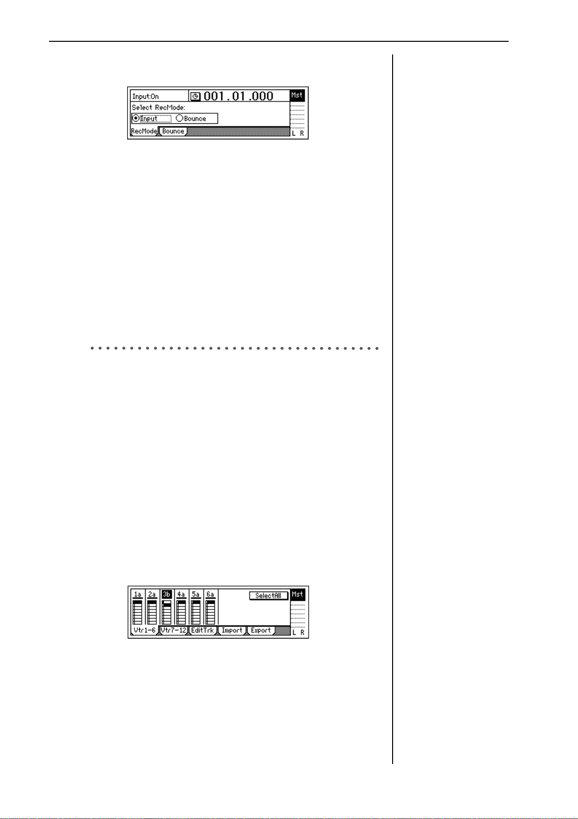
4 In the [BOUNCE] “RecMode” tab page, make sure that “Select Rec
Mode” is set to “Input.”
5 For this example, we will start recording from the beginning of the
song (“001.01.000” or “000:00.000”). If you are not at the begining,
hold down the [STOP] key and tap the [REW] key to return to the
begining of the song.
6 Enter record-ready mode.
Press the [REC] key (the [REC] and [PLAY] LEDs will blink).
7 Begin recording.
Press the [PLAY] key (the [REC] and [PLAY] LEDs will light).
Begin playing the keyboard.
8 Stop recording.
When you have finished performing, press the [STOP] key (the [REC]
and [PLAY] LEDs will go dark).
9 Listen to the overdub.
Return to the begining of the song. Press the track 9 and 10 [TRACK
STATUS] keys to set them to PLAY (lit green). Press the [PLAY] key.
4. Overdubbing additional parts
Next we’ll add a vocal on track 3.
1 Connect a mic to the [INPUT 1] jack.
2 Press the [MODELING] key to enter Modeling mode.
Select “MIC” as the Modeling Category.
3 Set the track 3 [TRACK STATUS] to REC.
When you enter Modeling mode, tracks 1 and 2 will be set to REC.
Press the track 1 and 2 [TRACK STATUS] keys to set them to PLAY,
and press the track 3 [TRACK STATUS] key to set it to REC.
4 Adjust the input level, recording level, and effects to prepare for
recording.
5 Move to the location at which you want to start recording, and start
recording.
Press the [FF] key or [REW] key to move to the desired time location.
Press the [REC] key and then the [PLAY] key to start recording.
When you are done, press the [STOP] key.
6 Let’s change virtual tracks to record another take.
Press the [TRACK] key to access the “Vtr1–6” tab page.
Counter display (→p.32)
When you have finished
recording, check to be sure
that your performance was
recorded correctly.
Use phantom power if you
have connected a condenser
mic.
Move to time (→p.32)
Virtual tracks (→p.53)
24
Select track “3a” and turn the [VALUE] dial to change it to “3b.”
7 Move the location again, and begin recording.
Move to the location from which you want to begin recording, and
press the [REC] key and then the [PLAY] key to begin recording.
8 Play back track 3.
Press the [TRACK STATUS] key to select PLAY, and press the [PLAY]
key to play back. At this time, track “3b” will play back.
If you want to play back a
track that you have already
recorded, set that track’s
[TRACK STATUS] to PLAY.
Page 27
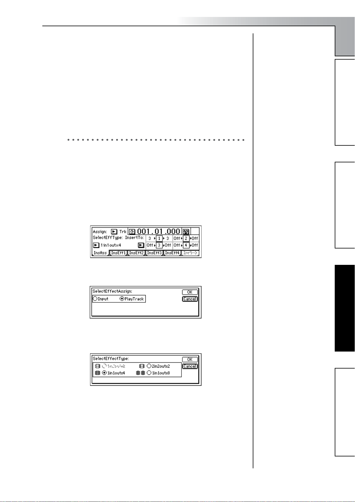
In order to play track “3a” which you recorded first, press the
[TRACK] key, access the “Vtr1–6” tab page, select “3b,” and turn the
[VALUE] dial to change it to “3a.”
Compare the two takes you recorded in virtual tracks “a” and “b.”
When you have decided which take is the best, leave that virtual
track selected.
Step 3. Mixing
In this step you will complete your song by applying effects to the tracks
and adjusting the volume and EQ to create the overall balance. This process is called “mixing.”
1. Applying an insert effect to a track
Previously, we applied the insert effects to the inputs, to process the
sound as we recorded. Here’s how to apply an insert effect into a mixer
channel, and process the playback sound of the track. In this example, we
are assigning an insert effect to the vocal(Mic) recording on track 3.
1 Select which tracks will be played back.
Press the [TRACK STATUS] key of each recorded track to select
PLAY mode (LED lit green), theplayback of the selected tracks will be
included in the mix.
2 Access the [INSERT EFFECT] “InsAss” tab page.
Quick Start Tutorial
To exit Modeling mode
(→p.47)
Step 1: Quick recordingStep 2: OverdubbingStep 3. Mixing
3 Select the “Assign:” button and press the [ENTER] key. In the dialog
box that appears, select “PlayTrack(Trk).”
When you have made your selection, press the [YES/OK] key.
4 Select the “SelectEffType:” button and press the [ENTER] key to
select the effect type.
For this example, select “1in1outx4.” Make your selection, and press
the [YES/OK] key.
Step 3. Mixing
Effect types (→p.42, 85)
Step 4. Mastering
25
Page 28
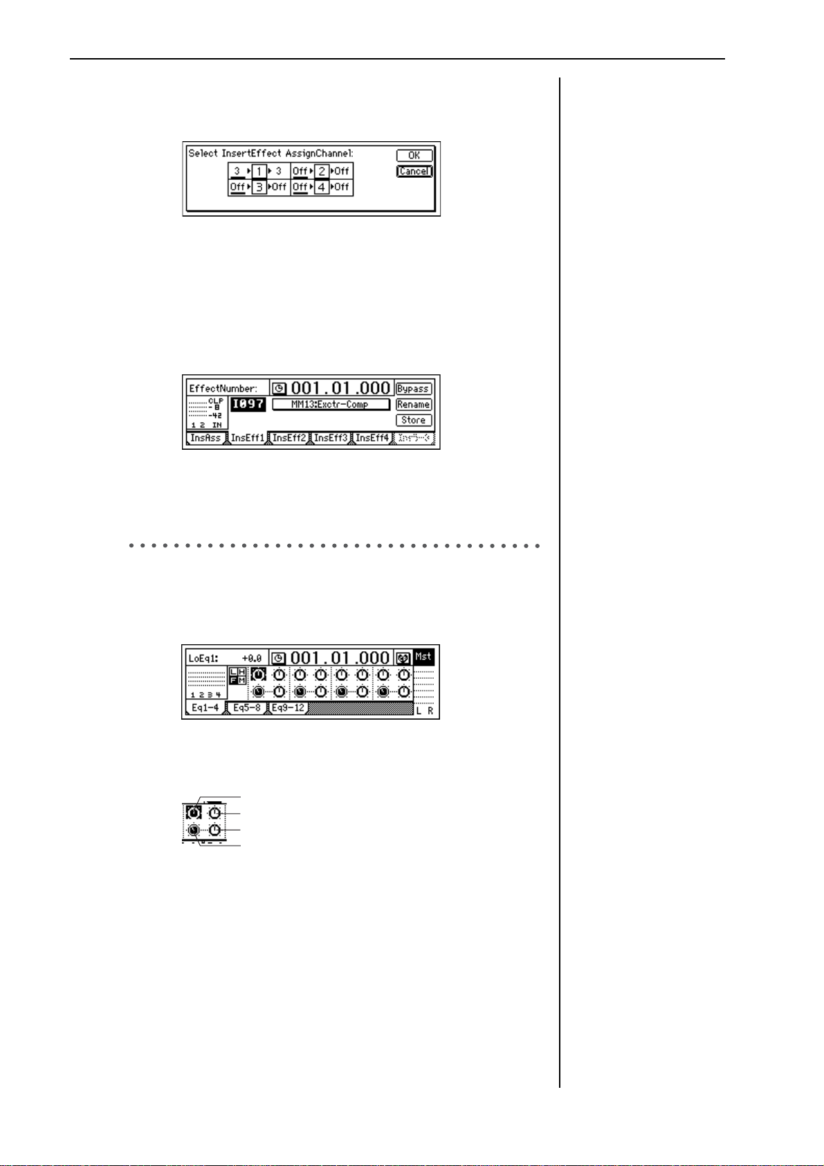
5 Specify the channel where you want to insert the effect.
Select the “InsertTo:” button, and press the [ENTER] key to open the
dialog box.
For each effect, turn the [VALUE] dial at “SelectCh” to select the
input (output) channel. For this example, set effect 1 to channel“3.”
When you have made the setting, press the [YES/OK] key.
6 Select an effect program.
In the insert effect “InsEff1” tab page, select the effect program that
you want to use.
Select “EffectNumber,” and turn the [VALUE] dial to select an effect
program.
7 Press the [PLAY] key to begin playback.
You can also select an effect program while you listen to the playback.
2. Adding EQ (equalization) to each track
1 Press the [EQ] key.
Select the [EQ] “EQ1–4,” “Eq5–8,” or “Eq9–12” tab page that contains
the EQ settings you want to adjust.
2 Select the EQ you want to adjust.
The following EQ controls are provided for each channel.
Low EQ gain (L)
High EQ gain (H)
Mid EQ gain (M)
Mid EQ frequency (F)
3 Adjust the gain and frequency.
Adjusting the gain in the “–” direction will cut the sound, and in the
“+” direction will boost the sound.
Raising the mid EQ frequency setting will cause the mid-range
boost/cut to affect a higher frequency range. Lowering it will cause
the boost/cut to affect a lower frequency range.
4 Press the [PLAY] key to start playback.
You can also adjust the EQ while you listen to the playback.
EQ (→p.37, 88)
26
Page 29
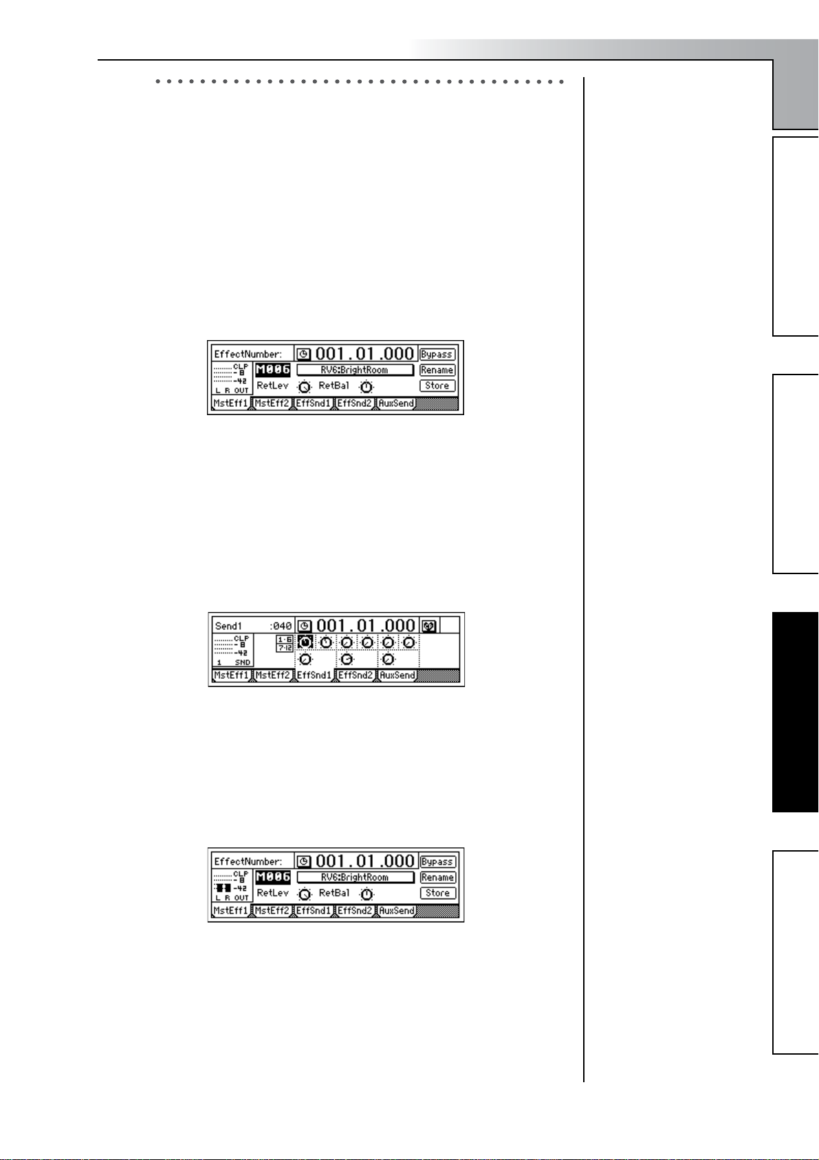
Quick Start Tutorial
3. Applying master effects to several tracks
Here we will select several tracks, and apply master effects to them.
The D1200 contains two master effects. By combining two different effects you can simulate complex spatial environments that could not be
produced by a single effect alone.
For example you could apply “RV1:ReverbHall” to master effect 1 and
“RV5:ReverbRoom” to master effect 2, so that you can vary the character
of the reverb applied to each instrument by adjusting the two send levels
on each channel.
In this way, you can use two different effects in conjunction with each
other to create complex spatial-type effects that could not be achieved by
a single effect.
1 Press the [MASTER EFFECT/AUX SEND] key to access the [MAS-
TER EFFECT/AUX SEND] “MstEff1” tab page.
2 Select an effect program.
Select “EffectNumber,” and turn the [VALUE] dial to select an effect
program.
3 Set the return level and return balance of the signal that is sent from
the master effect to master LR.
For this example, set “RetLev” (return level) to “100,” and “RetBal”
(return balance) to “CNT” (center).
4 Adjust the send levels.
The send levels from each channel to master effect 1 can be adjusted
in the “EffSnd1” tab page.
Step 1: Quick recordingStep 2: OverdubbingStep 3. Mixing
Effect Program List (→p.154)
Select each “Send” icon knob, and turn the [VALUE] dial to adjust
the send levels.
In this example, we will apply master effect 1 to tracks 1, 2, and 9/10.
5 Press the [PLAY] key to start playback.
While the song plays, listen to the master LR output and hear the
effects that are applied.
Adjust the return level and the send levels so that the master effect
level meters do not indicate “CLP.”
To apply master effect 2, make similar adjustments in the “MstEff2”
and “EffSnd2” tab pages.
Step 3. Mixing
Step 4. Mastering
27
Page 30
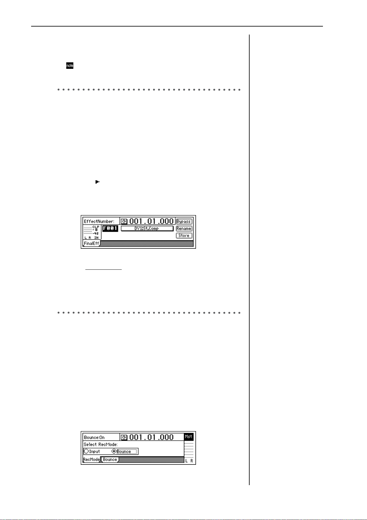
Step 4. Mastering
In this step, we create a final two-track mix and write it to CD-R to create
an original CD.
You will need the separately sold CDRW-1 in order to create a
CD.
1. Applying the final effect
Here we will adjust the pan and volume for each track, and apply a final
effect to the entire song.
The final effect is used mainly to apply a dynamics-type effect such as a
compressor, to make the overall level more consistent. You can apply an
effect such as a multi-band limiter to add the finishing touch to the sound.
1 Adjust the pan of each playback track.
Press the [PLAY] key to play back the song, and turn the [PAN] and
[BALANCE] knobs to adjust the stereo position of tracks 1–12.
2 Use the [CHANNEL] faders to adjust the playback level.
Press the [METER/TRACK VIEW] key to view the level meters.
Select the “ ” button and press the [ENTER] key to open the dialog
box. Select “PostFaderLev” to view the meters corresponding to each
fader.
3 Access the [FINAL EFFECT] “FinalEff” tab page.
4 Select an effect program.
Select “Ef
program.
Press the [PLAY] key to play back the song, and listen to the output
from the master LR or headphones to hear the effect.
When you have finished making adjustments, press the [STOP] key.
fectNumber,” and use the [VALUE] dial to select an effect
2. Creating the master track
In order to create an audio CD from a multi-track song, you will need to
combine the tracks into two tracks of data.
Here we will bounce-record the completed song, creating a stereo master
mix on tracks 1 and 2.
1 Use the [MASTER] fader to adjust the recording level.
Play back the entire song, and adjust the [MASTER] fader so that the
“CLP” indication does not appear for the master LR level meter.
2 Select the tracks where the master mix will be recorded.
For the tracks that you will record (tracks 1 and 2), set the [TRACK
STATUS] keys to REC. Set the remaining tracks (3–12) to PLAY.
3 Select bounce-recording as the recording mode.
Press the [BOUNCE] key to access the [BOUNCE] “RecMode” tab
page, and set “Select RecMode” to “Bounce.”
Effect Program List (→p.154)
Bounce-recording (→p.64)
28
Page 31

4 Select the bounce mode.
Access the [BOUNCE] “Bounce” tab page, and select “12Tr→2Tr” as
the “BounceMode.”
Quick Start Tutorial
5 Set “RecordVirtualTrack” to specify the virtual tracks (of the record
tracks) on which you will record.
If you want to record on the currently selected virtual tracks, select
“Current.”
6 Move the current location to the beginning of the song. (→p.32)
7 Begin bounce-recording.
Press the [REC] key to enter record-ready mode (LED blinking), and
press the [PLAY] key to begin recording (LED lit).
When you are finished recording, press the [STOP] key to stop.
8 Check the recorded content.
Press the [TRACK STATUS] keys of the recording tracks (1 and 2) to
select PLAY mode.
For the remaining tracks 3–12, either lower the faders to the minimum position or set their [TRACK STATUS] keys to MUTE.
Return to the begining of the song and press the [PLAY] key to hear
the results. Press the [STOP] key to stop.
3. Writing to CD
Finally we will use the CD-R/RW drive to create an original CD of the
song you just recorded. Press the [CD] key to access the “Prepare” tab
page.
1 First, let’s select the two tracks you bounce-recorded, and use Track
Monitor to listen to them.
In “SelTrks,” select the master tracks to which you bounce-recorded
your mix. For this example, select “1–2.”
If you select “Current,” your
mix will be recorded on the
same virtual tracks as were
played back. If you want to
keep the data of those virtual
tracks after bounce-recording, you must select virtual
tracks other than “Current.”
In order to create an audio
CD, the D1200’s internal hard
disk must have as much free
space as is occupied by the
song (the two-channel total)
you are creating. For example
in order to create an audio CD
of a five-minute song, you
must have enough free space
to accommodate ten minutes
of monaural recording.
Step 1: Quick recordingStep 2: OverdubbingStep 3. Mixing
Turn “TrackMonitor” on, and press the [PLAY] key.
You will hear tracks 1 and 2 which you selected in “SelTrks.”
2 Insert a commercially-available blank CD-R disc into the CDRW-1.
3 Access the [CD] “CDR/RW” tab page.
Make sure that “CD-R/RW Information” indicates “BlankDisc.”
4 Write to CD.
Select the “WriteToCD” button and press the [ENTER] key.
Select the writing speed. For this example, select “8X.” The disc will
be written at 8X speed.
If the song you write to CD
has no silence at the beginning (i.e., at time “zero”), you
may not hear the very beginning of the song when the CD
is played back. In such cases,
insert about half a second of
silence at the beginning
(“zero” time) of the two-track
mix. (→p.58: “InsertTrack”)
If you leave “TrackMonitor”
turned on, you can monitor
the playback without EQ or
effects being applied.
Since some audio CD players
will not play CD-RW discs,
we recommend that you use
CD-R discs to create audio
CDs.
Step 4. Mastering
Step 4. Mastering
29
Page 32

The “Obey Copyright Rules” message will appear.
Carefully read the section “COPYRIGHT WARNING” (→p.1) in the
owner’s manual, and press the [YES/OK] key if you accept the
terms.
Writing to disc will begin.
When writing is finished, the display will indicate “Completed.”
Press the [NO/CANCEL] key.
5 If you want to write another song, select a song then use steps 1–4
to write additional songs.
6 Finalize the disc.
If you want to be able to play back the disc, select the “Final” button
and press the [ENTER] key to finalize the disc.
While the disc is being written, you can select the
“Abort” button and press the
[ENTER] key to abort the
writing process. However,
this will produce an incomplete disc.
If you want to create another
CD with the identical contents, press the [YES/OK] key.
No further songs can be written to a disc that has been
finalized. Finalize the disc
only after you have written all
the songs you intend to write
to that disc.
A message will ask you to confirm the operation. If you are sure that
you want to finalize the disc, press the [YES/OK] key.
When finalization is completed, the “Completed” message will
appear, and the CDRW-1 tray will open. Press the [YES/OK] key.
7 Play back the disc on an audio CD player to verify that it plays cor-
rectly.
You and your Korg D1200 have now created an original CD of your
own performance!
30
Page 33

Operation
Song and Locate
1. Creating, naming and selecting songs
This section will cover how to create a song, how to name a
new or existing song, and how to select an existing song. The
D1200 has 100 song locations.
1-1. Creating a new song
Before you begin recording, you will need to create a new
song where the recording will take place.
1 Press the [SONG] key to access the “SelSong” tab page.
2
2 Use the [CURSOR] keys to select the “New” button, and
press the [ENTER] key.
The “MakeNewSong” dialog box will appear.
4
3
3 Use the radio buttons to select the bit depth (which will
determine the number of tracks), and the mixer settings.
Then press the [ENTER] key.
Use the “SongType” radio buttons to select the bit depth
and number of tracks, and press the [ENTER] key to
make the setting.
16Bit/12Track: A song using 16-bit recording/playback
will be created. Tracks 1-12 are available in this mode.
24Bit/6Track: A song using 24-bit recording/playback
will be created. Tracks 1-6 are available in this mode.
Select the desired “MixerSet” radio button in the same
way. (→p.116)
4 Press the [YES/OK] key.
A song named “NEWSONG” will be created following
the last existing song.
1-2. Editing the name of a song
Songs on the D1200 are designated by name. Song names can
be up to 16 characters in length. The D1200 contains 100 locations for songs, numbered 001–100. Songs are assigned to
these numbered locations in the order they are created. Both
the song names and the order number can be freely edited.
By default, each newly created song will be named
“NEW SONG.” So that you will be able to distinguish it
from other songs, we recommend that you assign a
name to your song before you continue.
1 Press the [SONG] key to access the “SelSong” tab page.
If you want to edit the name of a different song, select
that song first (→“1-3. Selecting different songs”).
2 Use the [CURSOR] keys to select the “Rename” button,
and press the [ENTER] key.
The “RenameSong” dialog box will appear.
4
3
3 Edit the song name.
Use the “ ” “ ” buttons to move the cursor. Then turn
the [VALUE] dial to edit the character.
The buttons in the display have the following function.
“0...9”: Selects numerals (e.g., “0”)
“A../a..”: Selects alphabetical characters (e.g., “A”).
Press this button again to select lowercase alphabetical characters (e.g., “a”).
“Symbol”: Selects symbols.
“Insert”: Inserts a space, moving subsequent charac-
ters backward.
“Space”: Selects a space (blank).
“Backsp”: Deletes the character that precedes the
cursor location.
“Delete”: Deletes the character at the cursor location.
“ClearAll”: Erases the entire name.
4 Finalize the changes.
If you are satisfied with the name you have made, press
the [YES/OK] key. If you decide not to change the name,
press the [NO/CANCEL] key.
1-3. Selecting different songs
There are three ways to select an existing song.
To select a song from the preceding or following song
location
• Hold down the [STOP] key and tap the [FF] key to
move to the end of the current song. Tap the key once
again to move to the beginning of the next song.
• Hold down the [STOP] key and tap the [REW] key to
move to the begining of the current song. Tap the key
once again to move to the beginning of the previous
song. If you are already at the beginning of the current song (e.g., “001.01.000”)holding down the
[STOP] key and tapping the [REW] key once will
locate the begining of the previous song.
Song and Locate
MixerEffects
Modeling mode
Rhythm
The Recorder
MasteringDataDriveUSBMIDIUpgrading
the system
31
Page 34

To select a song in a non-adjacent location
1 Press the [SONG] key to access the “SelSong” tab page.
2
2 Move the cursor to “SongNumber,” and turn the
[VALUE] dial to select a song number.
To select a song from the song list
1 Press the [SONG] key to access the “SelSong” tab page.
2
2 Select the “ ” button located at the left of the song
number, and press the [ENTER] key.
The song list will appear.
2 Select a location display method and press the [YES/
OK] key.
You can choose from the following four methods.
• . . “measures”, “beats”, “1/96th beats”
: . “minutes”, “seconds”, “1/1000th sec-
•
onds”
: . F “minutes”, “seconds”, “1/30 seconds”
•
. Free “minutes” .”seconds” (remaining amount
•
of recording time)
To check the remaining recording time
Access the “Select Time Disp Type” dialog box, and
choose “
To determine the correct “
STATUS] to REC for all the tracks that you want to
record. The display will indicate the recording time that
is available for recording on each track that is set to
REC.
. Free.”
. Free” time, set [TRACK
2-2. Changing the current location
Using the counter to move to a new location
1 Select a page in which the upper part of the display
shows the counter, such as the [SONG] “SelSong” tab
page.
2 In the counter, select the time field (e.g., measures, min-
utes, seconds) that you want to change.
3 Turn the [VALUE] dial or use the / buttons to
select a song, press the [ENTER] key, and then press the
[YES/OK] key.
2. Using the counter display
The counter indicates the current location within the selected
song. You can use the counter to program in and out points,
to “mark” locations, and to pinpoint an exact location when
using the “scrub” function.
2-1. Switching the counter display
You can select the type of units that the counter will use to
display the current location.
1
1 Select the “ ” button at the left of the counter, and press
the [ENTER] key to access the “Select Time Disp Type”
dialog box.
3 Turn the [VALUE] dial to move the current location.
Using [FF] and [REW] to move to a new location
Moving backward
Press the [REW] key to move backward in the song. You
will move continuously if you keep holding [REW]
down.
You may also use this method to move during playback.
Moving forward
Press the [FF] key to move forward in the song. You will
move continuously if you keep holding [FF] down.
You may also use this method to move during playback.
Moving to the beginning of the song
If you are currently not at the begining of the song, hold
down the [STOP] key and press the [REW] key to move
to the beginning of the song.
Moving to the end of the song
If you are currently not at the end of the song, hold
down the [STOP] key and press the [FF] key to move to
the end of the song.
32
Page 35

Operation
Using the Locate keys
You can register a specific location in one of the Locate keys,
and then jump instantly to that location.
You can register four locate points in each song using the
[IN/LOC1], [OUT/LOC2], [TO/LOC3], and [END/LOC4]
keys.
In addition to recalling the registered locate points,
these keys are also used to specify the auto-punch recording times (IN/OUT) and the region for track editing. For details on the Locate functions, refer to p.118.
Registering a location to one of the Locate keys
1 Use the counter (“Counter”) or the [FF]/[REW] keys to
move to the location you want to register.
2 Press the [STORE] key to memorize the location you
selected.
3 Press either the [IN/LOC1], [OUT/LOC2], [TO/LOC3],
or [END/LOC4] key to register the memorized location
to that key. The registration is completed as soon as you
press the key.
3 Press the [MARK] key to register a mark at the memo-
rized location. Registration is completed as soon as you
press the key. Marks are automatically renumbered
according to their playback order.
Even while the song is playing or recording, you can
memorize the current location and register it as a mark.
(The time at which you pressed the [STORE] key will be
registered.)
Moving to a registered Mark time
1 Access the [MARK] “Mark” tab page.
3
2
2 Use “MarkNumber” to select a mark.
3 Select the “Recall” button and press the [ENTER] key to
recall the mark.
You will move to the location of that mark.
Song and Locate
Song and Locate
MixerEffects
Modeling mode
Rhythm
Even while the song is playing or recording, you can
memorize the location by pressing the [STORE] key,
and register it to one of the Locate keys.
Moving to a registered Locate time
When you press any of the [IN/LOC1], [OUT/LOC2],
[TO/LOC3], or [END/LOC4] keys you will immediately move to the location regestered to that key
Using a Mark to move to a new location in the song
You can register up to 100 marks at desired locations
throughout your song, and jump instantly to a registered
mark.
You can give a name to each mark, and use it to remember a
certain place within the song.
Up to 100 marks can be registered in each song.
Registering a mark
1 Move to the location where you want to register a mark.
Use the counter or the [FF]/[REW] keys to move.
2 Press the [STORE] key to memorize the current location.
Deleting a mark
A mark you deleted cannot be recovered by Undo.
1 Access the [MARK] “Mark” tab page.
3
2
2 Use “MarkNumber” to select the mark that you want to
delete.
3 Select the “Delete” button and press the [ENTER] key to
open the dialog box.
4 Verify that “Delete Mark” in the upper left indicates the
mark you want to delete, and press the [YES/OK] key to
delete the mark. If you decide not to delete the mark,
press the [NO/CANCEL] key.
If you want to delete all marks, select the “SelectAll”
button and press the [ENTER] key. Then press the [YES/
OK] key to delete all the marks.
The Recorder
MasteringDataDriveUSBMIDIUpgrading
the system
33
Page 36

Naming a mark
• Select the “Rename” button and press the [ENTER]
key to open the “RenameMark” dialog box. For
details on the renaming procedure, refer to “1-2. Edit-
ing the name of a song” (→p.31)
• When you have finished inputting the name, press
the [YES/OK] key.
2-3. Using the Scrub function to find an exact
location
By using the Scrub function or the Play From/To function,
you can find the exact location where the sound begins, and
set a Locate time or Mark more precisely.
Scrub function
This feature allows you to hear a sound and view that
sound’s waveform to find a location within the song.
1 Press the [SCRUB] key to access the Scrub page.
3
3. Editing a song
Songs you have recorded can be copied (duplicated), deleted, or arranged in a different order. You can also protect a
song, to keep it from being accidentally deleted.
Song editing operations cannot be undone by the Undo
function.
3-1. Song editing operations
Copying a song: “CopySong”
This operation copies the selected song to the song number
you specify.
•You can use this to create alternative mixes or arrangements of the same song.
To copy a song
2
2 Use “TrackSelect” to select the track that you want to
play.
3 Select “Loc,” and turn the [VALUE] dial to search for the
location while you listen to the sound.
The track audio will play as you rotate the [VALUE]
dial.
Play From function
Press the [SCRUB] key to access the Scrub page, and
then press the [PLAY] key. The sound will begin playing
from the current location. After two seconds, it will stop
and automatically return to the location where you were
stopped.
Play To function
Press the [SCRUB] key to access the Scrub page, and
then hold down the [STOP] key and press the [PLAY]
key. The sound will begin playing from two seconds earlier than the current location, and will stop playing
when it reaches the location where you were stopped.
By using the Play From and Play To functions you can
find a location more accurately.
2
1,3 4 5
1 Select the song that you want to copy. (→p.31)
2 In the [SONG] “EditSong” tab page, move the cursor to
“EditType,” and turn the [VALUE] dial to select
“CopySong.”
3 Make sure “SourceSong” indicates the song you want to
copy.
4 Move the cursor to “DestSong,” and turn the [VALUE]
dial to select the song number where you want the copy
of the song to be located.
5 Select the “Exec.” button and press the [ENTER] key.
When “AreYouSure?” appears, press the [YES/OK] key
to execute the operation.
When the operation is completed, the display will indicate “Completed.” Press the [YES/OK] key to close the
dialog box.
Moving a song: “MoveSong”
This operation moves the selected song to a different song
number.
•You can use this to change the order of the songs.
To move a song
Slow Play function
Press the [SCRUB] key to access the Scrub page, and
press the [FF] key to play at half-speed from the location
at which you are currently stopped. When you press the
[STOP] key, playback will stop and you will return to
the previous location.
Since the audio will play slowly and at one octave below
the actual pitch, you can use this in conjunction with the
Pitch Shifter to learn, play along or practice complex
phrases that would be difficult to learn at full speed.
34
2
1,3 4 5
1 Select the song that you want to move. (→p.31)
2 In the [SONG] “EditSong” tab page, move the cursor to
“EditType” and turn the [VALUE] dial to select
“MoveSong.”
3 Make sure that “SourceSong” indicates the song you
want to move.
4 Move the cursor to “DestSong,” and turn the [VALUE]
dial to specify the destination song number.
Page 37

5 Select the “Exec.” button and press the [ENTER] key.
When “AreYouSure?” appears, press the [YES/OK] key
to execute the operation.
When the operation is completed, the display will indicate “Completed.” Press the [YES/OK] key to close the
dialog box.
Deleting a song: “DeleteSong”
This operation deletes the selected song.
To delete a song
2
1,3 4
1 Select the song that you want to delete. (→p.31)
2 In the [SONG] “EditSong” tab page, move the cursor to
“EditType” and turn the [VALUE] dial to select
“DeleteSong.”
3 Verify the song that you want to delete.
Make sure that “DestSong” indicates the song you want
to delete.
4 Select the “Exec.” button and press the [ENTER] key.
When “AreYouSure?” appears, press the [YES/OK] key
to execute the operation.
When the operation is completed, the display will indicate “Completed.” Press the [YES/OK] key to close the
dialog box
Operation
Mixer
1. Inputting audio to the mixer
The D1200 has four channels of analog input and one (twochannel) digital input. Audio from devices connected to
these input jacks can be assigned to the mixer channels, monitored and recorded. If the CDRW-1 CD-R/RW drive option
(sold separately) is installed, you can also assign the audio
from an audio CD to the mixer channels.
This section explains how to assign the various inputs to the
mixer channels.
1-1. Analog input
Create a new song before you proceed with the following
steps.
Connecting a guitar to the [GUITAR IN] jack, assigning it to
mixer channel 1, and adjusting the levels
1 Set the INPUT 1 [TRIM] knob to the minimum position
(+4 dB) and lower the [MASTER] fader. Then connect
your guitar to the [GUITAR IN] jack jack on the front
edge of the D1200.
2 Access the [INPUT/OUTPUT/SOLO] “Ch1–6” tab
page, select the “Ch1” icon, and turn the [VALUE] dial
to select “INPUT1.”
The [GUITAR IN] input jack is now assigned to mixer
channel 1.
Song and Locate
MixerEffects
Mixer
Modeling mode
Rhythm
Protecting a song: “ProtectSong”
This operation protects the selected song, preventing it from
being edited, rewritten or deleted.
If this Protect setting is turned on, it will not be possible to
write any parameters of that song; for example, an error will
be displayed if you attempt to record, and recording will
stop.
• When you have completed a song, you can use this to
prevent it from being accidentally rewritten or deleted.
To protect a song
2
1,3 4
1 Select the song that you want to protect. (→p.31)
2 In the [SONG] “EditSong” tab page, move the cursor to
“EditType” and turn the [VALUE] dial to select “ProtectSong.”
3 Make sure that “DestSong” indicates the song you want
to protect.
4 Switch the Protect setting on/off.
Select the “Exec.” button and press the [ENTER] key. A
“” symbol will be displayed to indicate the song is
protected. The on/off setting will alternate each time
you select the “Exec.” button and press the [ENTER]
key.
The Recorder
MasteringDataDriveUSBMIDIUpgrading
3 Press the track 1 [TRACK STATUS] key to set it to
INPUT (LED lit orange).
4 Press the [METER/TRACK VIEW] key. Select the “ ”
button and press the [ENTER] key to open the dialog
box.
Select the “PreFaderLev” radio button, press the
[ENTER] key, and press the [YES/OK] key.
When you play your guitar, the track 1 level meter will
move accordingly. While you watch the level meter,
adjust the INPUT 1 [TRIM] knob. Raise the [TRIM] knob
as far as possible without allowing the level meter to
reach the CLP level when you play your guitar at its
loudest level.
the system
35
Page 38

• Set the [MASTER] and [CHANNEL 1] faders to unity
gain (0 dB).
• Access the [INPUT/OUTPUT/SOLO] “Monitor” tab
page.
• Select the “MasterLR” button and press the [ENTER]
key to turn it “On” (highlighted).
• Slowly raise the [PHONES LEVEL] knob or [MONITOR OUT LEVEL] knob, and verify that you hear
sound from the headphones or from the monitor
speakers etc. connected to the [MONITOR OUT]
jacks.
1-2. Digital input
The D1200 lets you input and record a digital signal using
the S/P DIF input.
The S/P DIF input contains a sampling rate converter. If the
connected input source has a sampling rate of 48 kHz or 32
kHz, it will automatically be converted to 44.1 kHz.
Inputting audio from a DAT connected to the [S/P DIF IN]
jack into mixer channels 1 and 2
1 Lower the [MASTER] fader of the D1200, and use an
optical digital cable to connect the digital output of your
DAT to the [S/P DIF IN] jack.
2 Access the [INPUT/OUTPUT/SOLO] “Ch1–6” tab
page.
Select the “DigiIn” button, and press the [ENTER] key.
A message of “Obey Copyright Rules” will appear.
Using the tuner
The D1200 has a built-in tuner.
Here’s how to tune an instrument connected to the
[INPUT 1] or [GUITAR IN] jack.
1 Press the [TUNER] key to access the tuner screen.
2 Use “Calib” to specify the reference frequency.
Normally you will set this to “440 Hz.”
3 Play a note your instrument.
• The note name that is closest to the input pitch will
be displayed.
• If the pitch is correct, “ ” will appear at the 0 position in the center of the meter, and the “ ” (flat) and
““ (sharp) symbols will both light.
If the pitch is flat, only “ ” will light. If the pitch is
sharp, only “ “ will light.
The amount of pitch deviation is displayed in units of
cents. (100 cents = semitone; 1200 cents = 1 octave)
This page cannot be selected during recording or playback. Nor can you perform recording here.
In order to detect the pitch accurately, the effects will
automatically be turned off while this page is displayed.
Carefully read the owner’s manual section “COPY-
RIGHT WARNING” (→p.1), and if you accept the con-
ditions, press the [YES/OK] key in response to
“AreYouSure?” The digital input is now enabled.
3 Select the “Ch1” icon and turn the [VALUE] dial to
select “S/P DIF L.” Then select the “Ch2” icon and turn
the [VALUE] dial to select “S/P DIF R.”
The digital input from the [S/P DIF IN] jack is assigned
to mixer channels 1 and 2.
4 Play back your DAT, and press the track 1 and 2
[TRACK STATUS] keys to set them to INPUT (LED lit
orange).
5 Next, check the digital input audio levels. For instruc-
tions, refer to steps 3, 4, and 5 of “Connecting a guitar to the [GUITAR IN] jack, and assigning it to mixer
channel 1.”
Insert effects cannot be used when using digital input.
36
Page 39

2. Adjusting the mixer
In the mixer section you can create the overall “mix” by adjusting the volume, tone, and panning of the inputs that are
assigned to each mixer channel, or to the recorded sounds
that are being played back.
For details on adjusting the effects, refer to “Effects”
(→p.42).
2-1. Adjusting the volume
Use the [CHANNEL] faders to adjust the input, recording, or
playback volume of each channel. Raise or lower the fader to
set the appropriate volume.
The [CHANNEL] faders adjust the gain in a range from
silence (–∞) all the way up to +12 dB.
Normally you should set the faders to unity gain (0 dB the input signal is output at the same volume), and lower the faders of channels that are too loud rather than
raising the faders of channels that are too quiet. This will
make it less likely that the sound will clip (distort).
• If pairing is on, use the odd-numbered channel fader
to adjust the volume. (→p.37)
• Fader settings can be registered in a scene. (→p.39)
To adjust the volume level of each input channel
Use the [CHANNEL] faders to adjust the volume level
of each mixer channel assigned in the [INPUT/OUTPUT/SOLO] “Ch1–6” or “Ch7–12” tab page.
Since the output level will differ depending on the
equipment that is connected, use the [TRIM] knobs to
make adjustments as described in steps 3 and 4 of
“Connecting a guitar to the [GUITAR IN] jack, assigning it to mixer channel 1, and adjusting the levels”
(→p.35).
Operation
and record in stereo, set the [PAN] knob of the oddnumbered paired channel to the center.
2-3. Using EQ to adjust the tone
A three-band equalizer (EQ) is available to adjust the tone of
each input channel and each playback channel.
•To adjust the input sound (analog), make EQ adjustments in the [INPUT/OUTPUT/SOLO] “InEq1–4” tab
page.
These settings will affect the tone for recording.
•To adjust the track playback sound, make EQ adjustments in the [EQ] “Eq1–4,” “Eq5–8,” and “Eq9–12” tab
pages.
EQ is used to cut obtrusive frequency regions such as
hiss, or to cut or boost the low or high ranges. Normally,
you should adjust EQ so that the tone is clear and welldefined. Excessive EQ settings such as boosting the EQ
gain of each channel to the maximum value will make
the overall mix uneven, and cause listening fatigue. Use
EQ in the “cut” direction as well. It is best to use the
minimum amount of EQ that will achieve the desired
result.
• If pairing is on, use the odd-numbered “Eq” to make
adjustments. (→p.38)
• EQ settings can be registered in a scene. (→p.39)
Applying EQ to an analog input/Applying EQ as you
record
You can apply EQ to an analog input (not to the digital
input), and record the sound using these EQ settings.
1 Access the page that contains the channel where you
want the EQ to be applied, by selecting the [INPUT/
OUTPUT/SOLO] “InEq1–4” tab page.
Song and Locate
MixerEffects
Mixer
Modeling mode
Rhythm
The Recorder
To adjust the overall volume level
Use the [MASTER] fader to adjust the volume of the
master LR bus that is output from the headphones and
the [MASTER OUT] jacks.
2-2. Adjusting the pan
Use the [PAN] or [BALANCE] knobs to adjust the location of
each channel in the stero field.
• When pairing is on, the knob of the odd-numbered
channel can be used as a [BALANCE] knob to adjust the
position of the sound. (→p.38)
• Pan settings can be registered in a scene. (→p.39)
Channel 1–6 [PAN] knobs
Turn the knob toward L to move the sound left, or
toward R to move the sound right.
Channel 7–12 [BALANCE] knobs
Turn the knob toward L to increase the volume of the
odd-numbered channel. Turn the knob toward R to
increase the volume of the even-numbered channel.
Normally you will pan the vocals and bass to the center,
and spread the other instruments out across the stereo
field. As an example, guitar might be to panned to the
left, with the piano balancing it on the right.
When recording in stereo
If you want to input a stereo source to tracks 7/8–11/12
and record it in stereo, set the channel 7/8–11/12 [BALANCE] knobs to the center. Similarly, if you want to
turn pairing (=PAN) on for a pair of channels 1/2–5/6
2
3
2 Input an audio signal, and adjust the level appropri-
ately.
Refer to “Connecting a guitar to the [GUITAR IN] jack,
assigning it to mixer channel 1, and adjusting the levels”
(→p.35).
Verify that the level meter at the left edge of the display
moves, and that you can hear the sound.
3 Select the “InputEQ” gain settings and mid EQ fre-
quency, and turn the [VALUE] dial to adjust them.
High EQ, Low EQ
• Select “High EQ Gain (H)” or “Low EQ Gain (L)” for
the channel you want to adjust, and turn the
[VALUE] dial to adjust the gain. The value is shown
in the upper left of the screen.
Mid EQ
• Select “Mid EQ Frequency (F)” for the channel you
want to adjust, and turn the [VALUE] dial to adjust
the frequency. The value is shown in the upper left of
the screen.
• Select “Mid EQ Gain (M)” for the channel you want
to adjust, and turn the [VALUE] dial to adjust the
gain. The value is shown in the upper left of the
screen.
MasteringDataDriveUSBMIDIUpgrading
the system
37
Page 40

4 Record the sound as processed by the EQ. (→p.53)
Applying EQ to the track playback sound
• The EQ that is applied to the track playback sound can
be adjusted in the [EQ] “Eq1–4,” “Eq5–8,” and “Eq9–12”
tab pages.
Refer to Quick Start Tutorial. (→p.26)
2-4. Pairing
By specifying adjacent odd-numbered and even-numbered
channels (1–2, 3–4, 5–6) as a pair, you can adjust the values
of both channels simultaneously by editing the value of the
odd-numbered channel.
This is convenient when you want to make mixer settings for
a stereo-recorded track.
The following settings can be paired.
• [TRACK STATUS] key
• EQ (channel EQ)
•EffSnd1+2 (effect send)
• AuxSend (external send)
•[PAN] knob
• [CHANNEL] fader
The [TRACK STATUS] keys and [CHANNEL] faders
will be paired automatically when you pair two channels. For [EQ], [EffSnd], [AuxSend], and [Pan], you can
specify individually whether pairing will be enabled.
1 Select the “ ” (SelChPair) button in the [INPUT/OUT-
PUT/SOLO], [EQ], or [INSERT EFFECT] pages, and
press the [ENTER] key to open the “Select Channel
Pair” dialog box.
1
To select which signals will be monitored
1 Access the [INPUT/OUTPUT/SOLO] “Monitor” tab
page.
• Normally you will select “MasterLR.”
Select the “MasterLR” button and press the [ENTER]
key to turn it “On” (highlighted).
If the “Solo” function is on, it will overide any settings
here. Turn the “Solo” function off before making a selection.
2 For mixer channels whose [TRACK STATUS] is PLAY
(LED lit green), you will hear the track playback when
the recorder is playing.
For mixer channels whose [TRACK STATUS] is REC
(LED lit red), you will hear the sound of the external
input.
If the “AutoIn” button is “On,” and the [TRACK STATUS] of a mixer channel is “REC,” you will hear the
sound of that track during playback, and the sound of
the external input while recording and when stopped.
This is useful when doing “punch in/out” recording. If
“AutoIn” is “Off,” you will always hear the sound of the
external input.
3 Use the [MONITOR OUT LEVEL] knob to adjust the
volume of the [MONITOR OUT L/R] jacks, and the
[PHONES LEVEL] knob to adjust the volume of the
[PHONES] jack.
2 Here you can select which channels you would like to
pair. Select one of the “1 2”–“5 6” button, and press the
[ENTER] key so that the button is displayed with a
“.”
2
3
3 Select the functions that will be paired for the channels
you selected in “Select Channel Pair.”
Select the “Eq,” “Send,” “Aux,” and “Pan” function that
you want to pair, and press the [ENTER] key to turn
pairing “On.” Press the [YES/OK] key to apply the setting.
2-5. Monitor settings
In order to monitor the sound of the D1200, you must connect monitor speakers to the [MONITOR OUT L/R] jacks, or
connect headphones to the [PHONES] jack for monitoring.
2-6. Adjusting the cue level
The [CHANNEL] faders of the D1200 are used to adjust both
the recording level of each track and the volume level of each
channel, so the levels being recording will be the same as the
monitor volume levels.
For this reason, a Cue Level function is provided so that you
can monitor using a completely different mix of volume and
pan settings while you perform, regardless of the master LR
settings.
To adjust the Cue Level
1 In the [INPUT/OUTPUT/SOLO] “Monitor” tab page,
turn the “Cue” button “On.”
If the “Solo” function is on, it will overide any settings
here. Turn the “Solo” function off before making a selection.
2 Select the “Level” button and press the [ENTER] key to
access the Cue Level setting screen. Select the icons for
each channel, and turn the [VALUE] dial to adjust the
volume level and pan that is displayed in the upper left.
38
Page 41

Operation
2-7. Solo settings
If a “Solo” button is “On,” only that signal will be sent to the
monitor bus. Use this when you want to hear just one of several audio sources, or to check the send signal. The solo signal will be output from the [MONITOR OUT L/R] jacks and
the [PHONES] jack.
To select a signal for soloing
1 Begin by selecting the signal that you want to solo, and
turn Solo on. Access the [INPUT/OUTPUT/SOLO]
“Solo” tab page.
Select the appropriate “Solo” button, and press the
[ENTER] key to switch solo “On” (highlighted) for that
signal. If solo has been turned “On” for even one signal,
the [INPUT/OUTPUT/SOLO] key will blink.
You may select more than one signal for soloing.
2 Adjust the monitor volume.
Use the [MONITOR OUT LEVEL] knob or [PHONES
LEVEL] knob to adjust the volume level.
To turn solo off
• Access the [INPUT/OUTPUT/SOLO] “Solo” tab
page, and turn the “Solo” button(s) “Off.”
• If you select the “ClearAll” button and press the
[ENTER] key, all solo settings will be turned off.
To output the solo signal from master LR
You can output the solo signal from [MASTER OUT L/
R] if desired. Use this when you want to output the solo
signal from the monitor system connected to the [MASTER OUT L/R] jacks.
• In the [INPUT/OUTPUT/SOLO] “Solo” tab page,
turn the “SoloToMstOut” button “On” (highlighted).
However, this will automatically be turned “Off”
when you leave the [INPUT/OUTPUT/SOLO] page.
3. Registering and recalling a scene
The current mixer settings can be registered as a “scene.”
Scenes can be recalled automatically as the song plays. You
can also register frequetly-used mixer settings for recall as
desired, re-register the recalled settings at a different location, or edit some of the settings and overwrite them over the
original scene. Scenes can be renamed, and can be sorted by
their order of appearance in a song.
Up to 100 scenes can be registered in a song.
The following settings can be registered in a scene.
•EQ
•Effect settings
•EffSnd (effect send)
• AuxSend (auxilliary send)
•[PAN] and [BALANCE] knobs
• [CHANNEL] faders
The faders and pan/balance knobs of the top panel do
not actually move when a scene is recalled. However
the [SCENE] “MixView” tab page lets you see the value
for these settings as the scenes change.
3-1. Registering a scene
1 Move to the location in the song where you want to reg-
ister a scene.
Use the counter or [FF]/[REW] to move (→p.32).
2 Make the desired mixer settings.
Adjust the [CHANNEL] faders, [PAN] knobs, EQ, and
effects etc. to create a new scene.
3 To register the scene:
•Press the [STORE] key to capture the current time.
•Press the [SCENE] key. The display will indicate the
scene number as “SCENE***”, and the parameters
will be registered.
When a scene is registered, it is assigned the lowest unused number. You can perform step 3 even while a
song is being played or recorded.
3-2. Switching scenes during playback
Here’s how scenes can be automatically switched as the
playback time progresses.
Register scenes at the locations where you want the mix-
er settings to change. (→“3-1. Registering a scene”)
Automatically switching scenes while a song plays
1
Song and Locate
MixerEffects
Mixer
Modeling mode
Rhythm
The Recorder
MasteringDataDriveUSBMIDIUpgrading
1 Access the [SCENE] “ReadDel” tab page, and turn
“SceneRead” on.
• When this is on, the [SCENE] key will light.
2 Play back the song.
Move to the location from which you want to play back,
and press the [PLAY] key to play the song.
When you reach the location at which a scene was registered, the scene will change automatically.
the system
39
Page 42

3-3. Recalling a scene
At any time, you can manually recall the mixer settings registered in a scene, regardless of the time at which the scene
was registered.
To recall the mixer settings registered in a scene
2
1
1 Access the [SCENE] “ReadDel” tab page, and turn “Sce-
neRead” off.
• When this is off, the [SCENE] key will be dark.
If “SceneRead” is “On,” it will not be possible to recall a
scene that was registered at another time location.
2 Recall the scene.
In the [SCENE] “ReadDel” or “MixView” tab page,
move the cursor to “SceneNumber” and turn the
[VALUE] dial to select a scene. The selected scene will
be recalled.
3-4. Changing the time at which a scene is reg-
istered
You can change the counter location of a registered scene, so
that it is selected at a different place in the song.
2 Move to the location where you want to re-register the
scene. (→p.32)
3 Press the [STORE] key and then the [SCENE] key.
3-6. Editing and overwriting a scene
Here’s how to edit the settings of a scene and overwrite the
changes onto the existing scene.
1 As described in “3-3. Recalling a scene,” recall the scene
that you want to edit.
2 Adjust the [CHANNEL] faders, [PAN] knobs, EQ, and
effects etc. to the desired settings.
3 In the [SCENE] “ReadDel” tab page, make sure that the
scene number you want to overwrite is selected.
• Select the “OvrWrt” button and press the [ENTER]
key.
2
1 Recall the scene.
As described in “3-3. Recalling a scene,” select the scene
whose time you want to change.
2 Change the time of the scene.
• Select the “EditLoc” button and press the [ENTER]
key.
• Specify the desired counter locatioin in the dialog
box, and press the [YES/OK] key.
3-5. Re-registering a scene at another time
location
You can re-register the same scene at different locations.
1 Recall the scene that contains the mixer settings you
want to re-register.
As described in “3-3. Recalling a scene,” recall the
desired scene.
Press the [YES/OK] key to overwrite the settings for
that scene number.
3-7. Deleting a scene
Here’s how to delete an unwanted scene.
This operation cannot be undone.
2
1 As described in “3-3. Recalling a scene,” recall the scene
that you want to delete. If you want to delete all scenes,
select any of the scenes.
2 In the [SCENE] “ReadDel” tab page, select the “Delete”
button and press the [ENTER] key.
Verify the “Delete Scene” number shown in the upper
left, and if this is the scene you want to delete, press the
40
Page 43

Operation
[YES/OK] key to delete it. The scene will not be deleted
if you press the [NO/CANCEL] key.
If you want to delete all scenes, select the “SelectAll”
button and press the [ENTER] key to turn it “On.” Then
press the [YES/OK] key to delete all scenes.
3-8. Applying filtering to all scenes
Applying filters will allow you to prevent specific parameters on each channel from being affected by scene changes.
This can be a very handy feature.
1 In the [SCENE] “ReadDel” tab page, select the “Filter”
button and press the [ENTER] key to make the display
show “Select SceneFilter.”
2 Select the parameter(s) that you want to disable.
There are two pages of settings, so use the “Next” button to view the next page.
MIDI input
If “SceneRead” is “Off,” scene change messages (program changes) that are received will cause the D1200 to
select the scene of the corresponding number.
If “SceneRead” is “On,” these messages will not be
received, regardless of whether the D1200 is playing,
recording, or stopped.
1 Connect an external MIDI device. (→p.79)
2 In the [SYSTEM/USB] “MIDI” tab page, set “GlobalCh”
to match the channel of the external MIDI device that
will be transmitted the messages.
If you want the D1200 to transmit MIDI messages, set
the [SYSTEM/USB] “MIDI” tab page “ProgChange”
parameter “Trans” to “On.”
If you want the D1200 to receive MIDI messages, set the
[SYSTEM/USB] “MIDI” tab page “ProgChange”
parameter “Recv” to “On.”
3 In the [SCENE] “ReadDel” tab page, set “SceneRead” to
“Off”
4 Transmit a program change message from the external
MIDI device to recall a scene on the D1200.
When the D1200 receives program change #0 it will
recall scene “001.” Program changes #0–99 correspond
to scenes “001”–“100.”
Song and Locate
MixerEffects
Mixer
Modeling mode
Rhythm
The first page contains parameters for each channel. For
example if you want the Scene Filter to prevent scene
changes from affecting the pan settings of channels 1
and 2, you would turn “1,” “2,” and the “PanBal” button
“On.”
The second page contains parameters that apply to the
overall mix. As in the first page, turn “On” filtering for
parameters that you do not want to be affected by scene
changes. Press the [YES/OK] key to apply the settings.
3-9. Using MIDI to control scenes
MIDI output
When the scene changes, a scene change message (program change) will be transmitted in the following cases.
• When you use “SceneNumber” in the [SCENE]
“ReadDel” tab page to switch scenes.
• When you press the [STORE] key and [SCENE] key
to register a scene.
• When “SceneRead” is “On” and the scene changes
during playback or recording.
The Recorder
MasteringDataDriveUSBMIDIUpgrading
41
the system
Page 44

Effects
Overview of the effects
On the D1200 you can use up to eight insert effects that can
be applied to individul analog inputs or mixer channels, two
master effects that can be applied in varying amounts to the
send from each channel, and a final effect that can be applied
to the master LR as the last stage. Each of these effects are independent, meaning that you can simultaneously use up to
eleven effect programs.
•Effect algorithms: total of 98
•Effect programs:
Preset (192) User (192)
Insert effects I000, I001–I128 U001–U128
Master effects M000, M001–M032 u001–u032
Final effects F000, F001–F032 u033–u064
Preset effects contain effect programs created by professional musicians and studio engineers.
User effects can store effect programs that you created by editing a preset effect.
It is not possible to rewrite a preset effect program.
1. Using insert effects
These effects are “inserted” directly into the signal path of either an analog input signal or a playback track. Effects can
also be applied to the internal PCM rhythms if they are being
routed to a mixer channel.
There are four types of insert effects. The effect programs
that are available will depend on the type of effect you select.
(→p.127, 154)
1 in 2 out x 2, 1 in 1 out x 2 (input only)
These are mono-in/stereo-out or mono-out chain
effects. You can use two of these chain effects simultaneously.
These are ideal for adding spaciousness to a lead guitar
or vocal.
• When simultaneously recording guitar and bass, you
can apply a Guitar Multi effect to the guitar input
and a Bass Multi effect to the bass input as you
record.
• When simultaneously recording two vocals, you can
apply separate Vocal Multi effects to each vocal input
as you record.
• When simultaneously recording vocal and guitar,
you can apply a Vocal Multi to the vocal and a Guitar
Multi to the guitar as you record.
1 in 1 out x 4
These are mono-in/mono-out chain effects. You can use
four of these chain effects simultaneously.
These are ideal for sources whose stereo position is
fixed, such as rhythm guitar.
• When recording four vocals simultaneously, you can
apply Exciter-Comp to voices that lack impact, and
Limiter-P4EQ to powerful voices.
1 in 1 out x 8 (during track playback only)
Only during track playback, you can use eight monoin/mono-out effects.
These are ideal for sources whose stereo position is
fixed, such as drums.
•You can use Comp, Limiter, Gate, or Expander to
adjust the dynamics of each recorded track, or apply
Chorus, Phaser, or Delay.
In the case of a 24-bit song, only six of these effects can
be used.
1-1. Applying insert effects while you record
(analog or rhythm only)
While recording, you can apply effects to the input from instruments connected to the [INPUT 1/GUITAR IN]–[INPUT
4] analog input jacks or to the internal rhythm sounds if they
are input to a mixer channel. If the optional CDRW-1 is installed, you can also apply effects to the sound from an audio
CD.
Applying an effect to a guitar connected to the [GUITAR
IN] jack, and recording it to track 1
1 Plug in the guitar, and select the track where you want
to record.
Refer to “Connecting a guitar to the [GUITAR IN] jack,
assigning it to mixer channel 1, and adjusting the levels”
(→p.35).
2 Access the [INSERT EFFECT] “InsAss” tab page.
3
4 5
3 Select the “Assign:” button, and press the [ENTER] key.
Select “Input (In),” press the [ENTER] key, and press the
[YES/OK] key.
42
2 in 2 out x 2
These are stereo-in/stereo-out effects. You can use two
of these effects simultaneously.
These are ideal for a stereo input sources such as a keyboard.
• When simultaneously recording a keyboard and
rhythm machine, you can apply St.Chorus to the keyboard and St.Comp to the rhythm machine.
•You can apply St.Comp or St.Limiter to adjust the
dynamics of drums that are recorded in stereo, or
apply Reverb to create spaciousness (when playing
back the track).
4 Select one of the “SelectEffType:” buttons and press the
[ENTER] key to select the effect type.
Page 45

5 Insert the effect between INPUT 1 (GUITAR IN) and
channel 1.
• Select the “InsertTo:” button and press the [ENTER]
key.
Operation
You can achieve high-quality results by applying a mastering effect such as a multi-band limiter to add a finishing
touch to the sound during mastering.
1 Access the [FINAL EFFECT] “FinalEff” tab page.
2 Select an effect program.
Select “Ef
select an effect program.
Play back the song, and listen to the master LR output to
hear the result of the effect.
fectNumber,” and turn the [VALUE] dial to
Song and Locate
MixerEffects
Effects
• For “In1,” set “SelectCh” to “1,” and then press the
[YES/OK] key.
6 Select the effect program.
• Access the [INSERT EFFECT] “InsEff1” tab page.
• Select “EffectNumber,” and turn the [VALUE] dial to
select an effect program.
1-2. Applying insert effects during playback
You can apply insert effects to the playback of previously-recorded tracks.
For the procedure of applying insert effects to the track play-
back, refer to the Quick Start Tutorial. (→p.25)
2. Using the master effects
To use the master effects, set the Send Level of each track to
send its signal to the master effect. The master effects are
used to add depth to the overall mix, or improve the balance.
The D1200 provides two master effects (MstEff1 and
MstEff2), and they can be used simultaneously. The depth of
each effect is adjusted by the send level that is sent from each
track to the effect.
Use AUX send when you want to apply an external effect.
For details on using master effects, refer to the Quick Start
Tutorial. (→p.27)
4. Editing an effect
You are free to edit any effect program used as an insert effect, master effect, or final effect.
If you switch the “EffectNumber” or turn off the power
without saving, your edited effect settings will be lost. If
you want to keep your edited effect settings, you must
save them. (→p.44)
To edit an effect
1 Access the page for the effect you want to edit.
2
4
2 Select “EffectNumber,” and turn the [VALUE] dial to
select the effect program that you want to edit.
3 Listen to the sound of the effect program.
If you select the “Bypass” button and press the [ENTER]
key, bypass will be turned on (you will hear the sound
without the effect). If you then select the “Cancel” button and press the [ENTER] key, bypass will be turned off
(the effect will be applied once again). This lets you
compare the sound with and without effects.
4 Select the “EditEffect” button and press the [ENTER]
key. The dialog box will appear, showing the structure
of that effect.
3
7
Modeling mode
Rhythm
The Recorder
MasteringDataDriveUSBMIDIUpgrading
3. Using the final effect
The D1200 provides one stereo-in/out final effect. It is applied to the master LR signal.
The final effect is used mainly for dynamic processing (such
as compression) to regulate the overall level.
5
5 Turn off each individual effect as necessary.
Select the “(Effect On/Off)” button located below each
“(EffectIcon)” button, and press the [ENTER] key to
switch it on (highlighted) or off.
the system
43
Page 46

6 Edit the settings of each effect.
• Select the “(EffectIcon)” button of the effect you want
to edit, and press the [ENTER] key.
• Select a parameter, and use the [VALUE] dial to edit
the value. For details on each parameter, refer to the
“Effect Parameter List” (→p.127).
•You can hear the results of the effect by switching the
“Effect On/Off” field in the upper part of the dialog
box. This on/off setting is the same as the “(Effect
On/Off)” button in step 5. Changing one will also
change the other.
•You are done editing, press the [YES/OK] key. If you
want to adjust another effect, select its “(EffectIcon)”
button, press the [ENTER] key, and edit the parameters.
• In the “EffectAlgorithm” dialog box, press the [YES/
OK] key.
7 You can assign a name to your edited effect program.
• Select the “Rename” button and press the [ENTER]
key to open the “RenameEffect” dialog box. (→p.31:
“1-2. Editing the name of a song”)
• When you are done naming the effect, press the
[YES/OK] key.
5. Controlling an effect from an external device
You can use an expression pedal or external MIDI controller
to control certain insert effect parameters in realtime.
For details on the effect parameters that can be controlled, re-
fer to “Effect Parameter List” (→p.127).
Using a pedal to control an insert effect
1 Connect an expression pedal (such as the optional EXB-
2 foot controller) or an external MIDI controller (→p.14).
2 Access the [SYSTEM/USB] “Control” tab page.
• In “Device (CtrlChgDevice),” select “Pedal” if you
want to use an expression pedal for control.
3
If you want to use MIDI to control the effect, select the
MIDI message. In order to use MIDI messages for control, you must set the [SYSTEM/USB] “MIDI” tab page
“GlobalCh (Global Channel)” setting to match the MIDI
channel of the external MIDI device that will transmit
the messages.
3 Chose which insert effect will be controlled.
Use “Ass(#)(CtrlChgAssign)” to select “InsEff1”–
“InsEff4” as the insert effect that will be controlled.
To save the effect program
• If the song is playing, press the [STOP] key to stop
playback.
• Select the “Store” button and press the [ENTER] key
to open the “StoreEffect” dialog box.
• Specify the number in which you want to save the
effect program, select the “Exec.” button, and press
the [ENTER] key to save the effect program.
When you save the effect program, the data will be
overwritten to that number and any existing settings
will be lost.
4 Assign an effect program.
• Go to the [INSERT EFFECT] “InsEff1”–“InsEff4” tab
page, and select the insert effect that you selected in
step 3.
• Select “Effect Number,” and turn the [VALUE] dial to
select the effect program.
If the selected effect contains a control function and can
be controlled, a “#” symbol will be displayed after the
name of that effect program.
5 Specify the parameter and range that will be controlled.
• Select the “(EffectProgramName)” button and press
the [ENTER] key.
The “Effect Algorithm” dialog box will appear, show-
ing the structure of that effect program.
Edit Cntrl Icon
44
Page 47

• Select the “EditCntrl Icon” button, and press the
[ENTER] key to open the “ControlDevice” dialog
box.
• Select “Param,” and turn the [VALUE] dial to select
the parameter that you want to control.
•Turn the [VALUE] dial to set “Max” to the maximum
value and “Min” to the minimum value.
• When you have finished making settings, press the
[YES/OK] key.
• In the “Effect Algorithm” dialog box, press the [YES/
OK] key.
If you want to save these settings, save them as described on p.44.
6 Now you can operate the expression pedal or external
MIDI controller to control the effect.
Operation
Modeling mode
The D1200 provides a Modeling mode that makes it easy for
you to record using Korg’s ToneWorks REMS effects. Dedicated knobs allow you to control the modeling effects as easily as if you were using hardware devices. Refer to “What is
REMS?” (→p.6)
In Modeling mode, tracks 1 and 2 are automatically selected
and their [TRACK STATUS] is set to REC (lit red). You can
begin recording immediately, simply by pressing the [REC]
key and then the [PLAY] key.
When you overdub, be sure to record to different tracks
so you don’t erase anything you had already recorded.
Set the [TRACK STATUS] keys of the overdub tracks to
REC (red).
If you want to record in monaural, set only one track to
a [TRACK STATUS] of REC (red).
The D1200 remembers the last state of Modeling mode
even when the power is turned off, and will be available
when you turn the power on again.
A modeling effect you edit cannot be saved as an effect
program as it is. Edited Modeling effects must be saved
as an insert effect user program. (→p.46)
Song and Locate
MixerEffects
Modeling mode
Modeling mode
6. Using an external effect
You can take the Send signal from the [AUX OUT] jack and
run it through an external effect processor. The output of the
external effect can then be connected to the [INPUT 1]–[INPUT 4] jacks, and returned to the mixer channels or to the
master LR bus.
Sending the playback sound to an external effect, and
using [INPUT 3] and [INPUT 4] jacks to return it to the
master LR bus
1 Connect the D1200’s [AUX OUT] jack to the INPUT jack
of the external effect, and connect the OUTPUT jacks of
the external effect to the D1200’s [INPUT 3] jack and
[INPUT 4] jack.
2 Set the send levels for each channel.
• Access the [MASTER EFFECT/AUX SEND] “AuxSend” tab page.
• Select “Aux” for the channel(s) that you want to send
to the external effect, and use the [VALUE] dial to
adjust the send level.
3 Return the audio signal from the external effect unit.
• Access the [INPUT/OUTPUT/SOLO] “Ch1–6” or
“Ch7–12” tab page.
• Select the “SubIn” button, and press the [ENTER]
key to open the dialog box. Use the “In3–4” “Fader”
to adjust the return level, and “Balance” to adjust the
return balance. (→p.67, 98)
1. Applying a modeling effect to your guitar
The D1200 provides various modeling effects for use with a
guitar, including simulations of distortion-type effect devices, amp heads, and speaker cabinets.
1 Press the [MODELING] key, move the cursor to “Gui-
tar” in the left of the screen, and press the [ENTER] key
or the [YES/OK] key to enter the guitar modeling effect
screen.
2 3 45
2 Select a distortion-type effect.
Of the three knobs located below the display, turn the
left knob “DRIVE” to select one of the ten distortiontype modeling effects.
3 Select a pre-amp tone.
Turn the center knob (TONE) to adjust the tone of the
vacuum tube premp model. Vacuum tubes add a unique
non linear distortion that modifies the overtone structure of the sound.
4 Select the cabinet.
Turn the right knob (CABINET) to choose one of eleven
cabinet types.
5 Edit the effect parameters.
Move the cursor to “DRIVE,” “TONE,” or “CABINET”
in the display, and press the [ENTER] key to access a
screen where you can edit the parameters of the corresponding effect.
Rhythm
The Recorder
MasteringDataDriveUSBMIDIUpgrading
45
the system
Page 48

For example if you select “TONE,” three parameters
will appear; “BASS,” “MIDDLE,” and “TREBLE.”
You can adjust these parameters by turning the three
knobs located below the display. If you want to make
more precise adjustments, turn the [VALUE] dial to
adjust the value.
To return to the previous screen, move the cursor to the
“Exit” button in the upper right of the display and press
the [ENTER] key, or press the [CANCEL] key.
If the guitar input level is not appropriate, you may not
obtain the distortion or noise reduction effect you expect. Watch the input peak LED while you use the input
trim to adjust the level so that it is neither too low or too
high (clipping).
2. Applying a modeling effect to your bass
The D1200 provides various modeling effects for use with a
bass, including dynamics-type effects as well as modulation
and ambience-type effects such as chorus and delay.
These effects can also be applied to clean (undistorted)
guitar sounds.
1 Press the [MODELING] key, move the cursor to [Bass]
in the middle of the screen, and press the [ENTER] key
or the [YES/OK] key to enter the bass modeling effect
screen.
2
the trim control to adjust the level appropriately for the
input.
3. Applying a modeling effect to a mic
The D1200 provides various modeling effects for use with a
mic, such as simulations of different types of studio, mic, and
dynamics-type effects. These effects are ideal for processing
signals from a dynamic mic or line input.
1 Press the [MODELING] key, move the cursor to [Mic] at
the right of the screen, and press the [ENTER] key or the
[YES/OK] key to enter the mic modeling effect screen.
2
3
2 Use the knobs located below the display to select the
desired type for studio, mic, and dynamics.
3 Edit the effect parameters.
Move the cursor to “STUDIO,” “MIC SIM,” or
“DYNAMICS” in the display, and press the [ENTER]
key to access a screen where you can edit the parameters
of the corresponding effect. For example if you enter the
DYNAMICS screen, three parameters will appear;
“ATTACK,” “RELEASE,” and “LEVEL.” You can adjust
these parameters by turning the three knobs located
below the display. If you want to make more precise
adjustments, turn the [VALUE] dial to adjust the value.
If the input level is too low or too high, dynamics-type
effects may not produce the result you expect. According to your input source, adjust the trim to obtain an appropriate level.
If you are using line input, set the MIC SIM “IN MIC”
parameter to “Line.” If you are using a dynamic mic, set
the “IN MIC” parameter to the type of mic you are using.
3
2 Use the knobs located below the display to select the
desired type for the dynamics, vacuum tube, and ambient effects.
3 Edit the effect parameters.
Move the cursor to “DYNAMICS,” “TONE,” or “AMBIENT” in the lower part of the display, and press the
[ENTER] key to access the effect parameter screen for
the corresponding effect.
For example when you access the DYNAMICS screen,
the three parameters “ATTACK,” “RELEASE”, and
“LEVEL” will appear. You can adjust the values of these
three parameters by turning the three knobs located
below the display. If you want to make precise adjustments to a parameter, you can also use the [VALUE] dial
to edit the value.
If the sound is distorted, you can either lower the input
trim or lower the “DYNAMICS” level.
If the input level for the dynamics-type effect is not appropriate, you may not obtain the result you want. Use
46
4. Saving your modeling effect settings
The modeling effects you edit in Modeling mode are preserved even when the power is turned off. When you turn on
the power again, the state of the three effects (for guitar, bass,
and mic) will be preserved.
A modeling effect that you edit in Modeling mode can also
be edited in greater detail as an insert effect. You will then be
able to save the edited insert effect as a user program, and recall it when desired.
You cannot use Modeling mode to edit an effect program that has been saved as an insert effect.
Page 49

Operation
If you want to edit the effect in greater detail and save it
1 Edit the effect in Modeling mode (→p.45).
2 Access the [INSERT] “InsEff1” tab page.
The [MODELING] key will go dark.
The display will show the insert effect program that you
had been editing as a modeling effect.
3 Edit the settings as an insert effect, and save.
Refer to “To edit an effect” (→p.43) and “To save the
effect program” (→p.44).
For details on using an effect program that you saved,
refer to “1. Using insert effects” (→p.42).
To exit Modeling mode
To exit Modeling mode, press the [NO/CANCEL] key
several times to make the [MODELING] key go dark.
To restore the factory settings
Press the “ ” button, and the selected modeling effect
will return to the factory settings.
5. Operation in Modeling mode
Limitations in Modeling mode
• Only the [INPUT 1] or [GUITAR IN] jacks can be
used.
• The [INPUT/OUTPUT/SOLO] “Ch1–6” and “Ch7–
12” tab pages will be displayed as follows, and you
cannot make Input settings in Modeling mode.
• The last-used modeling effect settings will be
restored.
When you exit Modeling mode
• The [MODELING] key will go dark.
•With the exception of tracks whose [TRACK STATUS] is set to REC, the audio input settings to the
mixer will return to the state prior to when you
entered Modeling mode.
When you change the track status
If you change the [TRACK STATUS] while in Modeling
mode, the “InsertTo” setting of the insert effect will
change as follows.
• If you make settings for monaural recording by setting only one [TRACK STATUS] to REC, the
“InsertTo” setting will change to “In1→1→upper line
(the track set to [REC]) lower (off)”.
• If you make settings for stereo recording by setting
two [TRACK STATUS] key to REC, the “InsertTo”
setting will change to “In1→1→upper line (the track
set to [REC]) lower line (the track set to REC +1)”.
• If you have not set [TRACK STATUS] to REC, the
“InsertTo” setting will not change.
Song and Locate
MixerEffects
Modeling mode
Modeling mode
Rhythm
•A maximum of two tracks can be recorded simultaneously.
• If you play back a scene or switch scenes while in
Modeling mode, the insert effect settings registered
in that scene will not be reflected.
•You cannot set [TRACK STATUS] to INPUT (orange).
5-1. Internal operation in Modeling mode
In Modeling mode, various functions will be set automatically in the following cases.
When you enter Modeling mode
• The [MODELING] key will light.
• All current assignments in the [INPUT/OUTPUT/
SOLO] “Ch1–6” and “Ch7–12” tab pages will be
memorized, the “DigiIn” button will be turned off,
and all input channel settings will be set to “1.”
“SubIn” will be muted.
• The [BOUNCE] “RecMode” tab page “RecMode”
will be set to “Input.”
• [TRACK STATUS] for track 1 and track 2 will be set
to REC, and the remaining tracks will be set to PLAY.
• In the [INSERT EFFECT] “InsAss” tab page, the
insert effect assignment will be set to “Input(In),”
and the effect type will be set to “1in2outx2.”
“InsertTo” will be set to In1→1→upper line (1) lower
line (2).
• The insert effect 1 program will be changed.
The Recorder
MasteringDataDriveUSBMIDIUpgrading
the system
47
Page 50

Rhythm
2. Listening to the rhythm while you
The D1200 contains numerous rhythm patterns in a variety
of time signatures (→p.156: “Rhythm Pattern List”).
When you have a sudden idea for a song, you can record a
performance immediately by using these rhythm patterns as
a guide track.
You can also join different rhythm patterns to create drum
patterns for an entire song.
1. Selecting and playing a rhythm
Access the [RHYTHM] “SetUp” tab page.
Use this page to make the settings described below.
TempoSource
SelRhythm RhythmVol RhythmOn/Off
Turning the rhythm on/off
Select the “Rhythm On/Off” button and press the
[ENTER] key to turn it “Rhythm:On” (highlighted).
The [RHYTHM] key will light, and the currently
selected rhythm will sound.
The rhythm will sound during playback and recording.
If you want to record the rhythm, refer to “3. Recording
the rhythm.”
Adjusting the rhythm volume
Select “RhythmVol” and turn the [VALUE] dial to adjust
the volume.
Setting the tempo and time signature
1 Select “TempoSource” and choose the tempo source.
For this example, we will select “Manual,” so that the
tempo, time signature, and rhythm pattern will not
change.
You can also select the “ ” button and press the [ENTER] key to choose from a list.
If you want to change the tempo, time signature, and
rhythm pattern during the song, you must create a
tempo map. (→p.49)
2 Select “Tempo,” and turn the [VALUE] dial to adjust the
tempo.
3 Select “Beat,” and turn the [VALUE] dial to specify the
time signature.
Tempo Beat
record a performance
Here’s how you can listen to the rhythm pattern as a guide
while you record your playing.
1 Use the procedures described in “1. Selecting and play-
ing a rhythm” to turn the “Rhythm” “On” and make
any other necessary settings.
2 Connect your instrument, and get ready to record.
Refer to “1. Assigning inputs to the mixer” (→p.22).
Press the [REC] key to enter record-ready mode, and the
rhythm will start playing. Press the [PLAY] key and
recording will begin. Play along with the rhythm pattern you selected.
With these settings, the rhythm cannot be recorded.
3. Recording the rhythm
Here’s how you can take a rhythm pattern and record it as
part of your song.
Recording a rhythm pattern on tracks 1 and 2
1 Make settings as described in “1. Selecting and playing a
rhythm.”
•Turn “Rhythm” “Off.”
If this is “On,” the sound will be output in duplicate;
both to the tracks and to the master LR bus.
• The volume will be adjusted by the mixer input
channels. The“RhythmVol” is the send level only to
the master LR bus, so you do not need to set it.
• Make any other settings as necessary.
2 Specify the input channels.
• Select the [INPUT/OUTPUT/SOLO] “Ch1–6” tab
page.
• Select the “Ch1” icon, and turn the [VALUE] dial to
select “RhythmL.” In the same way, set “Ch2” to
“RhythmR.”
3 Record the rhythm.
Refer to “1-1. Basic recording” (→p.53).
Selecting a rhythm pattern
Select “SelRhythm,” and turn the [VALUE] dial to
choose a rhythm pattern.
You can also select the “ ” button and press the [ENTER] key to choose from a list.
48
Page 51

4. Setting the tempo of a song
By selecting one of the three options for “TempoSource”you
can either play an entire song at the same tempo, change the
tempo during the song, or synchronize it with an external
MIDI device.
• Manual tempo: The entire song is played at one tempo.
•Tempo map: Tempo changes can be programmed
throughout the song.
•Tempo track: MIDI Clock or tap tempo will control the
tempo.
Manual tempo
The settings you specify for “Tempo” (tempo), “Beat” (time
signature), and “SelRhythm” (rhythm pattern) will be used,
and will not change during the song.
1 To select the Manual settings as the tempo source:
• Access the [RHYTHM] “SetUp” tab page.
• Select “TempoSource,” and turn the [VALUE] dial to
choose “Manual.”
Operation
Tempo map “001” specifies the tempo at the beginning
of the song, and tempo maps “002”–“200” can be used
to change the tempo at subsequent measures.
• Select the “Edit” button, and access the “Select
TempoMap001 Param” dialog box.
• Specify the tempo in “Tempo,” the time signature in
“Beat,” and the rhythm pattern in “Rhythm.”
• Use the ending measure of “Meas” to specify the
number of measures that tempo “001” will continue.
The starting measure of tempo map “001” cannot be
changed from measure “001.”
• When you have finished making settings, press the
[YES/OK] key.
3 Create a new tempo map to change the tempo, time sig-
nature, and rhythm pattern during the song.
• Select the “New” button and press the [ENTER] key.
The display will read “Select TempoMap002 Param.”
Song and Locate
MixerEffects
Modeling mode
For more about “Tempo,” “Beat,” and “SelRhythm,” re-
fer to “1. Selecting and playing a rhythm” (→p.48).
Tempo map
Tempo maps let you change the tempo, time signature, or
rhythm pattern at the various specified measures. By using
tempo maps to change rhythm patterns, you can create a
drum track for the entire song, including an intro, breaks,
fill-ins, and an ending.
1 Using Tempo Map as the tempo source.
• Access the [RHYTHM] “SetUp” tab page.
• Select “TempoSource,” and turn the [VALUE] dial to
choose “TempoMap.”
2 Specify tempo map “001” at the beginning of the song.
• Access the [RHYTHM] “TmpMap” tab page.
• Specify the“Tempo,” “Beat,” and “Rhythm” settings
that you want to use for this new tempo map.
• Use “Meas” to specify the starting measure and ending measure at which tempo map “002” will be
inserted.
•Press the [YES/OK] key to add the tempo map.
When you add a tempo map, any subsequent tempo
maps will be renumbered upward, so that they are
always numbered consecutively from the beginning
of the song to the end of the song.
• By adding tempo maps, you can create drum patterns for an entire song, including an intro, breaks,
fill-ins, and an ending.
Rhythm
Rhythm
The Recorder
MasteringDataDriveUSBMIDIUpgrading
2
• Select “TempoMap,” and turn the [VALUE] dial to
choose tempo map “001.”
3
2
4 Listen to the tempo maps you created.
In the [RHYTHM] “SetUp” tab page, set “TempoSource” to “TempoMap.” In the [RHYTHM] tab page,
set “Rhythm:On.”
the system
49
Page 52

Move to the beginning of the song, and press the [PLAY]
key to play back the song. The rhythm pattern and
tempo will change according to the tempo maps that
you created.
You can also check the tempo maps in the [SONG]
“SelSong” tab page.
If you want to record the sound of the rhythm as played
by the tempo maps you created, refer to “3. Recording
the rhythm” (→p.48).
• Display the tempo map list, and check the tempo
map.
Adding a tempo map to insert a rhythm pattern
If you want to create a new tempo map, press the
“Insert” button.
A tempo map will be inserted at the specified measure,
and the measure numbers of subsequent tempo maps
will move backward by the corresponding number of
measures.
1 Check the location at which you want to insert the
tempo map.
• Display the tempo map list, and check the current
tempo map. In this example, we will insert a tempo
map at the beginning of the song.
Editing a tempo map
If you increase the number of measures, the measure
numbers of subsequent tempo maps will move backward by the corresponding length. If you decrease the
number of measures, the measure numbers of subsequent tempo maps will move forward by the corresponding length.
1,3
1 Select the tempo map that you want to edit.
• Display the tempo map list, and select the tempo
map that you want to edit.
2 Edit the settings.
• Select the “Edit” button. A dialog box will appear.
2
2 Create a new tempo map.
• Select the “NEW” button and press the [ENTER] key
to open the dialog box.
• Set the parameters.
•Turn the “Insert” button “On,” and press the [YES/
OK] key.
3 Verify that the tempo map was inserted correctly.
• Display the tempo map list, and check the tempo
map.
• Edit the parameters, and press the [YES/OK] key.
3 Verify that you have made the settings you want.
50
Overwriting a tempo map
If you want to add a tempo map to replace the rhythm
pattern, turn off the “Insert” button when you create the
new tempo map.
Page 53

Operation
The tempo map of the specified measure(s) will be
replaced, but the overall number of measure will not
change.
1 Verify the location at which you want to insert a tempo
map.
• Display the tempo map list, and check the current
tempo map.
2 Create the new tempo map.
• Select the “NEW” button and press the [ENTER] key
to open the dialog box.
• Set the parameters.
2 Delete the tempo map.
• Select the “Delete” button. A message of “Are You
Sure?” will ask you to confirm.
•Press the [YES/OK] key, and the selected tempo map
will be deleted.
If you turn the “Select All” button “On,” all maps other
than “001” will be deleted, and the settings of map
“001” will also be deleted.
3 Verify that the tempo map was deleted.
• Display the tempo map list, and verify that the map
was deleted.
Song and Locate
MixerEffects
Modeling mode
•Turn the “Insert” button “Off,” and press the [YES/
OK] key.
3 Verify that the tempo map was replaced as you
expected.
• Display the tempo map list, and check the tempo
map.
Deleting a tempo map
The maps located after the deleted map will move forward by the number of measures that were deleted.
1 Select the tempo map that you want to delete.
• Display the tempo map list, and select the appropriate tempo map.
This operation cannot be undone.
• If you want to edit the tempo map, select the “Edit”
button and press the [ENTER] key to open the dialog
box. Edit the parameters as necessary. Press the
[YES/OK] key to accept the new settings.
Tempo track
The tempo track records MIDI clock data from an external
MIDI sequencer, or tap tempo data.
Recording MIDI Clock data from an external MIDI
sequencer, and using it as the tempo track
Here’s how MIDI Clock data from an external MIDI
sequencer can be recorded as tempo data on the tempo
track.
You can use this when you want to synchronize a D1200
song with song data created on a MIDI sequencer in
which the tempo changes continuously.
1 Specify the time signature of the song.
If the time signature of the song data created on your
MIDI sequencer changes during the song, create a new
tempo map that begins where the time signature
changes. (→p.49)
If you want the time signature to change during the
song, you must create tempo maps accordingly. Tempo
settings will play back in synchronization, but measures
will become incorrectly aligned if the time signature
changes do not match.
2 Connect the MIDI OUT connector of your MIDI
sequencer to the D1200’s [MIDI IN] connector.
3 Set your MIDI sequencer so that it will transmit MIDI
Clock messages.
Refer to the owner’s manual of your MIDI sequencer.
4 Select how tempo will be recorded.
In the [RHYTHM] “TmpTrk” tab page, select “MIDI
Clock.”
Rhythm
Rhythm
The Recorder
MasteringDataDriveUSBMIDIUpgrading
the system
51
Page 54

5 Record the MIDI Clock data.
•Press the “RecStart” button and press the [ENTER]
key to put the D1200 in record-ready mode.
• Start your MIDI sequencer.
• When the MIDI Clock data from the MIDI sequencer
begins arriving, the display will indicate “ReceivingMIDIClock.”
6 When the MIDI sequencer has finished playing, stop the
MIDI sequencer.
When recording is completed on the D1200, the display
will indicate “Complete.”
Press the [YES/OK] key.
7 Select the Tempo Track as the tempo source.
• Access the [RHYTHM] “SetUp” tab page.
If you want the time signature to change during the
song, you must create the appropriate tempo maps.
Tempo settings will play back in synchronization, but
measures will become incorrectly aligned if the time signature changes do not match.
3 If you want to use a foot switch to input the tap tempo,
connect an optional PS-1 foot switch to the [FOOT
SWITCH] jack of the D1200.
4 Choose how you will record the tempo.
In the [RHYTHM] “TmpTrk” tab page, select either
“MeasTap” (tap at the beginning of each measure) or
“BeatTap” (tap at each beat).
5 Record the tap tempo track.
• Select the “RecStart” button and press the [ENTER]
key. The D1200 will enter the record-ready mode.
• Select “TempoSource,” and turn the [VALUE] dial to
specify “TempoTrk.”
If MIDI Clock data was not received correctly from your
MIDI sequencer, recording may stop in the middle of
the song.
Tap tempo
You can record the tempo by pressing (tapping) the
[PLAY] key at the beginning of each measure or on each
beat while the song plays.
You can use a PS-1 foot switch (sold separately) instead
of the [PLAY] key.
Tap tempo lets you record the tempo after a song has
already been recorded. If you record tempo for a song
for which you did not originally specify the tempo, you
will be able to do the following things.
• Edit tracks in units of measures
• Connect and synchronize external MIDI devices
1 Prepare the audio for which you want to record the
tempo.
Record the audio from the beginning of the song.
When recording from the beginning of the song, it is
convenient to use Trigger recording. (→p.54)
2 Specify the time signature of the song.
If the time signature changes during the song for which
you want to record tempo, create a tempo map at the
location where the time signature changes.
• When you press the [PLAY] key or a connected foot
switch, the song will begin playing, and tap tempo
recording will also begin.
• While you listen to the playback, record the tap
tempo by pressing the [PLAY] key or foot switch at
the intervals you specified in step 4. The counter
will be displayed while you record the tap tempo.
When using the [PLAY] key to record tap tempo, do not
strike the key any more forcefully than necessary. Doing
so may damage the hard disk etc.
6 After you have input the last tap, press the [STOP] key.
For example if you are inputting four measures of a 4/4
time signature, tap four times in the case of “MeasTap”
or sixteen times in the case of “BeatTap” to input up to
the beginning of the fifth measure. Then press the
[STOP] key.
If you input taps only until mid-way through the song,
the tempo of the last-input measure or beat will be automatically copied to the end of the song.
7 Specify the tempo track as the tempo source.
Access the [RHYTHM] “SetUp” tab page, select “TempoSource,” and turn the [VALUE] dial to choose “TempoTrk.”
Move to the beginning of the song, and press the [PLAY]
key to play back the song and check the tempo.
52
Page 55

The Recorder
1. Recording
You can connect audio sources such as guitar and keyboard
to the input jacks, make mixer settings to assign these audio
input sources to tracks of the recorder, and then record them.
The D1200 has twelve recording/playback tracks, and each
of the twelve tracks has eight virtual tracks.
Input1
Input2
Input3
Input4
Digital In
L
R
L
Dr
R
L
CD
R
CDRW-1
[INPUT/OUTPUT/SOLO]
“Ch1-6”, “Ch7-12”
Ch1: Track 1
Ch2: Track 2
Ch3: Track 3
Ch4: Track 4
Ch5: Track 5
Ch6: Track 6
Ch7: Track 7
Ch8: Track 8
Ch9: Track 9
Ch10: Track 10
Ch11: Track 11
Ch12: Track 12
Operation
high as possible without allowing the level bar to
reach “CLP.”
4 Move the counter location to the point in the song where
you want to begin recording. (→p.32)
Start recording from the beginning of the song
(“001.01.000” or “000:00.000”).
5 Press the [REC] key (the [REC] and [PLAY] LEDs will
blink).
6 Press the [PLAY] key (the [REC] and [PLAY] LEDs will
light).
Begin performing on your instrument.
7 When you are finished performing, press the [STOP]
key (the [REC] and [PLAY] LEDs will go dark).
Listen to the playback to verify that your performance
was recorded correctly.
1-2. Switching the virtual track for recording
The D1200 has twelve tracks, and each of these provides
eight virtual tracks, labeled a-h.
For example when you record a solo part, you can record
two or more “takes,” each on their own virtual track, and select the best one later. Or when bounce-recording (pingpong recording), you can specify two unrecorded virtual
tracks as the recording-destination, allowing you to combine
twelve tracks of data into two tracks without erasing any ex-
isting tracks. (→p.64)
Song and Locate
MixerEffects
Modeling mode
The following pages explain how to record audio on these
tracks.
1-1. Basic recording
Here’s how to record the audio signal that you specified in
“1. Inputting audio to the mixer” (→p.35).
If you want to create a new song for recording, set refer
to “1-1. Creating a new song” (→p.31).
1 Check the recording mode.
Access the [BOUNCE] “RecMode” tab page. Set “Select
RecMode” to “Input” (=record the input audio).
2 Press the [TRACK STATUS] key for the track that you
want to record, to set the status to REC (LED lit red).
3 Use the [CHANNEL] fader to set the recording level.
•Press the [METER/TRACK VIEW] key.
• Select the “ ” button and press the [ENTER] key to
select “PostFaderLev,” and press the [YES/OK] key.
Recording on a different virtual track
1 Select a virtual track.
In the [TRACK] “Vtr1–6” or “Vtr7–12” tab page, select
the track that you want to record, and turn the [VALUE]
dial to select an unrecorded virtual track.
Recorded track
Selected track
2 Adjust the recording level of the input device, and
record.
Refer to “1-1. Analog input” (→p.35).
1-3. Recording while you listen to other tracks
play
The process of recording while you listen to other tracks play
is called “overdubbing.” For example you can use this to
record a solo while listening to previously-recorded backing
tracks.
1 Check the recording mode.
Access the [BOUNCE] “RecMode” tab page. For “Select
RecMode,” choose “Input” (= record the audio input).
Rhythm
The Recorder
The Recorder
MasteringDataDriveUSBMIDIUpgrading
• Slowly raise the [CHANNEL] fader, and the level
meter of the input channel will move according to
the level of the input signal. Adjust the level to be as
2 Use the [CHANNEL] fader to set the recording level.
Refer to “1-1. Basic recording.”
the system
53
Page 56

3 Select the playback tracks.
Press the [TRACK STATUS] keys of the tracks that you
want to hear, and set them to PLAY (LED lit green).
4 Select the recording track.
Press the [TRACK STATUS] key of the track that you
want to record, to set it to REC (LED blinking red).
5 Mute tracks that you do not want to use.
For each track that you do not want to play or record,
press the [TRACK STATUS] key to set it to MUTE (LED
dark), so that no sound will be output by tracks that you
are not using.
6 Adjust the recording level of the input device, and
record.
Refer to “1-1. Analog input” (→p.35).
Trigger recording procedure
Trigger recording is a function that initiates recording
when the input volume reaches a specified level.
1 Connect your input device, select a track for recording,
and adjust the recording level. Refer to “1-1. Basic
recording” (→p.53).
2 Access the [TRIGGER] “Trigger” tab page, and turn
“TriggerRec” “On” (the [TRIGGER] key will light).
• Select the signal that you want to monitor.
•Turn on the “AutoIn” button.
3 Move the counter to a location slightly before the point
where you want to begin re-recording. (→p.32)
4 Press the [PLAY] key to begin playback. You will hear
the recorded tracks play, including the recording-destination track.
5 At the point you want to begin re-recording, press the
[REC] key.
Recording will begin (manual punch-in). Now you will
hear the external input source.
6 At the point you want to stop re-recording, press the
[REC] key or [PLAY] key.
Recording will stop, and playback will resume (manual
punch-out). Now you will again hear the track playback.
7 Press the [STOP] key to stop.
When you have finished recording, move the current
location to a point slightly earlier than where you began
recording, and listen to the re-recorded performance.
3 Press the [REC] key to select record-ready mode (LED
blinking).
4 Begin playing your instrument.
When the input signal exceeds the threshold level
(“Threshold”), recording will begin automatically.
5 When you are finished playing, press the [STOP] key to
stop recording.
1-4. Re-recording a specific area: Punch-in/out
If you make just one mistake in a recorded performance, or
are not satisfied with a portion of the performance, you can
use “punch-in/out” recording to fix just that portion without having to re-record from the beginning of the song.
“Punch-in” is the action of switching the song from the playback to the record mode, and “punch-out” is the action of
switching from the record mode back to the playback mode.
Manual punch-in/out
Here’s how you can punch-in and punch-out manually.
During playback, press the [REC] key or an optional PS-1
foot switch to begin recording, and then press the [REC] key,
[PLAY] key, or foot switch to stop recording.
1 Connect your input device, select a track for recording,
and adjust the recording level. Refer to “1-1. Basic
recording” (→p.53).
2 Specify the monitor output.
• Access the [INPUT/OUTPUT/SOLO] “Monitor” tab
page.
Using a foot switch for manual punch-in/out
You can switch between playback and recording by
pressing a PS-1 foot switch (sold separately).
This lets you punch-in/out while you perform, or when
the D1200 is located at a distance.
1 Connect a foot switch to the [FOOT SWITCH] jack.
2 Access the [SYSTEM/USB] “Control” tab page.
3 Specify the function of the foot switch.
Set “Func (FootSwFunction)” to “PunchIn-Out.”
4 Perform steps 5 and 6 of “Manual punch-in/out,” but
press the foot switch instead of the [REC] key. (You may
use the foot switch and [REC] key in conjunction with
each other.)
You can also use the foot switch to record from the beginning of the song. To do so, set “Func” in step 3 to
“Play/Stop.”
At the beginning of the song, press the [REC] key (the
LED will blink), and then press the foot switch to begin
recording.
Auto punch-in/out
The auto punch-in/out function automatically performs a
punch-in and punch-out at pre specified locations.
1 Access the [AUTO PUNCH] “AtPunch” tab page. In the
[AUTO PUNCH] “AtPunch” tab page, select the “Auto
Punch” button, and press the [ENTER] key to turn it
54
Page 57

Operation
“On.” This turns on the auto punch-in/out recording.
The [AUTO PUNCH] key will light.
2 Set the [IN/LOC1] point (punch-in) to specify the loca-
tion where you want to begin recording, and set the
[OUT/LOC2] point (punch-out) to specify the location
where you want to stop recording.
For details on how to register the [IN/LOC1] and
[OUT/LOC2] locations, refer to “Registering a location
to one of the Locate keys” (→p.33).
In the [AUTO PUNCH] “AtPunch” tab page, you can
select the “Wave” button and press the [ENTER] key to
view the waveform, allowing you to set the IN and OUT
points more accurately.
The time locations you specify will overwrite the previously-specified locations for the [IN/LOC1] and [OUT/
LOC2] keys.
3 Connect your input device, select a track for recording,
and adjust the recording level. Refer to “1-1. Basic
recording” (→p.53).
4 Specify the monitor output signal.
Refer to “Manual punch-in/out” 2. (→p.54)
5 Specify how much of the song will play before recording
begins, and how much will play after recording ends.
In the [AUTO PUNCH] “AtPunch” tab page, press the
“RolTime” button and press the [ENTER] key to open
the “SetRollTime” dialog box.
•Turn the [VALUE] dial to set “PreRoll” to the length
that will play before recording begins, and set
“PostRoll” to the length that will play after recording
ends. Use “Unit” to select the unit by which to set to
pre-roll and post-roll times. You can select either
“Second” (seconds) or “Meas” (measures).
• When you have finished making your settings, press
the [YES/OK] key to return to the previous page.
6 Begin recording.
• When you press the [REC] key, you will move to a
point earlier than the specified punch-in point (by
the distance of the pre-roll time), and enter recordready mode (LED blinking).
• When you press the [PLAY] key, playback will begin.
The track will play back during the pre-roll time, and
recording will begin at the punch-in (IN) point. (The
[REC] LED will be lit.)
7 Stop recording.
• Recording will stop when you reach the punch-out
(OUT) point and switch to play back. (The [REC]
LED will blink.)
• After the post-roll time has elapsed, playback will
stop, and you will automatically return to the point
specified by the pre-roll time.
8 Listen to the re-recorded results.
Loop recording
When using auto punch-in/out recording, you can switchthe “Loop” function on so that the IN–OUT region will be recorded repeatedly (as a loop). When you are finished
recording, you can use the Undo/Redo function to compare
the takes that you recorded, and select the best one.
Loop recording procedure
1 Make auto punch-in/out settings.
Refer to steps 1–5 of “Auto punch-in/out” (→p.54).
2 In the [LOOP] “Loop” tab page, turn “Loop” “On.”
3 Begin recording.
• When you press the [REC] key, you will move to the
begining of the pre-roll time, and enter record-ready
mode. (The [REC] key LED will blink.)
•Press the [PLAY] key to begin playback.
Playback will occur during the pre-roll time, and
recording will begin when you reach the IN time.
(The [REC] key LED will light.)
When you reach the OUT time, recording will end and
the post-roll region will play back. (The [REC] key LED
will blink.)
When the post-roll time ends, you will automatically
move to the beginning of the pre-roll time, and the same
operations will be repeated.
•Press the [STOP] key at a point outside the recording
area (IN–OUT) to stop.
4 Use the Undo/Redo function to compare the recorded
content, and choose the best take.
•Press the [UNDO] key to display the Undo list. The
Undo list shows “RecordTrack” for the most recent
recording (Level00) and each preceding recording
(Level (= the number of loops you recorded minus
1)).
Recordings that you made before you performed loop
recording will also appear in the list as “RecordTrack.”
•From the Undo list, turn the [VALUE] dial to choose
a recorded take. Then select the “Undo” button and
press [ENTER]. The selected take will be recalled.
5 Listen to the recorded content.
•Press the [PLAY] key to play back, and listen to the
recorded content. If “AutoPunch” is “On,” playback
will begin at the begining of the pre-roll time, and
continue to the end of the post-roll time.
Song and Locate
MixerEffects
Modeling mode
Rhythm
The Recorder
The Recorder
MasteringDataDriveUSBMIDIUpgrading
the system
55
Page 58

• Repeat this procedure to find the best take.
If you are satisfied with the selected take, press the
[YES/OK] key to return to the previous screen.
If you want to select the most recent recording, select the
“Redo” button and press the [ENTER] key to return to
the “Level00” take.
2. Playback
This page explains how to perform basic playback, and how
to use program playback.
To play back a song program list
1 Access the [SONG] “PrgPlay” tab page.
2 Press the [PLAY] key to begin playback.
The programs will play in the order of the list, starting
with the first song.
During playback, you can press the [FF] key to move to
the next song. Pressing the [REW] returns you to the
begining of the current song. If you are already at the
begining of the current song, pressing the [REW] key
will move to the beginning of the previous song.
3 Press the [STOP] key to stop playback.
You can use “program list playback” only while the
“PrgPlay” tab page is displayed.
2-1. Playback
1 Select the track(s) that you want to play.
For each track that you want to play, press the [TRACK
STATUS] key to set it to PLAY mode (LED lit green).
2 Move to the counter location from which you want to
play.
For details on how to move to a new location, refer to
p.32.
3 Begin playback.
Press the [PLAY] key. (The [PLAY] LED will light.)
• Apply EQ to the playback. (→p.37)
• Adjust the level and pan of the playback. (→p.37)
• Apply effects to the playback. (→p.42)
• Play the built-in rhythm along with the playback.
(→p.48)
4 Stop playback.
Press the [STOP] key. (The [PLAY] LED will go dark.)
Even if there is no more audio, playback will not stop
until you press the [STOP] key.
You can also use a PS-1 foot switch (sold separately) to
start or stop playback (→p.101).
2-2. Program playback
This function lets you play two or more songs in the order
you specify.
It is convenient to use this when recording to DAT or MD.
2-3. Other types of playback
Playing back a different virtual track
As described in “1-2. Switching the virtual track for
recording” (→p.53), select a virtual track that you
recorded, and play it back.
Loop playback
This repeatedly plays the IN–OUT region of the song.
This lets you check the contents of that region, or can be
used in conjunction with auto-punch recording to per-
form loop recording. (→p.54)
1 Select the track(s) that you want to play.
For each track that you want to play, press the [TRACK
STATUS] key to set it to PLAY mode (LED lit green).
2 Register the region (IN–OUT) that you want to loop.
(→p.33, 118)
These settings can also be made in [LOOP] “Loop” or in
[AUTO PUNCH] “AtPunch” tab page “Wave.”
3 Access the [LOOP] “Loop” tab page, and turn the
“Loop” button “On.”
To create a program play list
1 Access the [SONG] “PrgPlay” tab page.
2 Select the song you want to play first.
Use the scroll buttons to select “01” in the program play
list, and turn the [VALUE] dial to choose a song.
3 In the same way, select the second and following songs.
To delete a song from the program play list, select that
song and turn the [VALUE] until it reads “- - -”.
The program play list will be preserved until you turn
off the power.
56
4 Begin loop playback.
When you press the [PLAY] key, playback will begin at
the IN point, and the IN–OUT region will play repeatedly.
5 Press the [STOP] key to stop playback.
Page 59

3. Track editing
You can use track editing commands to copy a track, insert
blank space, erase a track, delete a track, reverse a track, optimize a track, exchange tracks, expand/compress a track,
copy an entire track, exchange two entire tracks, create a
fade-in/fade-out, or normalize the level.
In some cases, track editing may not be possible if there
is insufficient space on the song drive. You will need to
allocate enough free space for the track editing operation (equivalent to the IN–OUT or TO–END time).
3-1. Preparations for track editing
• In order to perform track editing, you must first register
the region (the area of time) that you want to edit.
• Move to the counter location that you want to register.
•Press the [STORE] key, and then press one of the follow-
ing keys to register the time in that key. (→p.33)
[IN/LOC1] key: IN time
[OUT/LOC2] key: OUT time
[TO/LOC3] key: TO time
[END/LOC4] key: END time
• Select a virtual track. (→p.53)
Operation
Use “DestTrack” to select track “2.”
If you selected two or more tracks for “SourceTrack,”
you must specify the same number of tracks for “DestTrack.”
5 Specify the number of times that the data will be copied.
Set “Times” to “3.”
6 Select the “Exec.” button and press the [ENTER] key.
When the display asks “AreYouSure?,” press the [YES/
OK] key to execute the operation.
When the operation has been completed, the display
will indicate “Completed.” Press the [YES/OK] key.
The copied data will be overwritten onto the copy-destination track.
7 Check the results of the editing operation.
Press the [TO/LOC3] key, and play back from the TO
location to verify that the data was copied correctly.
If you are not satisfied with the results, you can use
Undo to return to the previous state. (→p.126)
Copying track data to a track in a different song
Here’s how the IN–OUT region of track 1 in song 001
can be copied once to the TO location of track 2 in song
002.
Song and Locate
MixerEffects
Modeling mode
3-2. Track editing procedures
Copy a track: “CopyTrack”
This command copies the specified region (IN–OUT) of track
data to another location (TO).
• The IN–OUT region can be copied once, or multiple
times in succession.
•You can copy data from one track, or from multiple
tracks simultaneously.
• By using the clipboard, you can copy track data to a different song.
Here are some ways in which you can use this command.
• Repeatedly copy a phrase of several measures (such as a
drum pattern) to create a track that extends the entire
length of song.
• Copy the first verse of a song to create the second verse.
• Record a favorite phrase from a track, and copy it to a
different track or song.
Copying track data within the same song
Here’s how the IN–OUT region of track 1 can be copied
three times starting at the TO location of track 2.
1 Select song 001.
2 Register the IN and OUT locations. (→p.33, 118)
3 Select “CopyTrack.”
In the [TRACK] “EditTrk tab page, select “EditType”
and use the [VALUE] dial to choose “CopyTrack.”
4 Select the copy-source track number.
Use “SourceTrack” to select track “1.”
5 Select the clipboard as the copy-destination track.
Use “DestTrack” to select “Clip.”
6 Select the “Exec.” button and press the [ENTER] key.
When the display asks “AreYouSure?,” press the [YES/
OK] key to execute the operation. When the operation
has been completed, the display will indicate “Completed.” Press the [YES/OK] key.
The copied data will overwrite the data in the clipboard.
Rhythm
The Recorder
The Recorder
MasteringDataDriveUSBMIDIUpgrading
1 Register the IN, OUT, and TO locations. (→p.33, 118)
Use the IN time to specify the beginning of the copysource region, the OUT time to specify the end of the
copy-source region, and the TO time to specify the location to which the data will be copied.
2 Select “CopyTrack.”
In the [TRACK] “EditTrk tab page, select “EditType”
and use the [VALUE] dial to choose “CopyTrack.”
3 Select the copy-source track number.
Use “SourceTrack” to select track “1.”
4 Select the copy-destination track number.
7 Select song 002.
8 Register the TO location. (→p.33, 118)
9 Select “CopyTrack.”
In the [TRACK] “EditTrk tab page, select “EditType”
and use the [VALUE] dial to choose “CopyTrack.”
0 Select the clipboard as the copy-source track.
Set “SourceTrack” to “Clip1.” The number indicates the
number of tracks in the clipboard.
A Select the copy-destination track number.
the system
57
Page 60

Use “DestTrack” to select track “2.”
B Specify the number of times that the data will be copied.
Set “Times” to “1.”
If you selected two or more tracks for “SourceTrack,”
you must specify the same number of tracks for “DestTrack.”
C Select the “Exec.” button and press the [ENTER] key.
When the display asks “AreYouSure?,” press the [YES/
OK] key to execute the operation.
When the operation has been completed, the display
will indicate “Completed.” Press the [YES/OK] key.
The copied data will be overwritten onto the copy-destination track.
D Check the results of the editing operation.
Press the [TO/LOC3] key, and play back from the TO
location to verify that the data was copied correctly.
If you are not satisfied with the results, you can use
Undo to return to the previous state. (→p.126)
Erase a track: “EraseTrack”
This command erases recorded data from the specified region (IN–OUT) of a track. The region will become blank.
Unlike the Delete Track command, this Erase Track command does not move the data that follows the OUT time.
•You can erase data from the IN–OUT region of one or
more tracks simultaneously.
Erasing data from a track
Here’s how to erase the IN–OUT region of track 1.
DestTrack
Insert blank space: “InsertTrack”
This command inserts blank space into the specified region
(IN–OUT) of a recorded track. Track data following the inserted space will be shifted toward the end of the song.
•You can insert space into one or more tracks simultaneously.
This can be used in ways such as the following.
• If you want to add a phrase to the middle of a recorded
performance, insert a space of the appropriate length,
and then record into that area.
Inserting blank space
Here’s how to insert blank space into the IN–OUT
region of track 1.
DestTrack
1 Register the IN and OUT times. (→p.33, 118)
2 Select “InsertTrack.”
In the [TRACK] “EditTrk” tab page, select “EditType”
and use the [VALUE] dial to choose “InsertTrack.”
3 Select the track number into which the blank space will
be inserted.
Use “DestTrack” to select track “1.”
4 Select the “Exec.” button and press the [ENTER] key.
When the display asks “AreYouSure?,” press the [YES/
OK] key to execute the operation.
When the operation has been completed, the display
will indicate “Completed.” Press the [YES/OK] key.
5 Check the results of the operation.
Press the [IN/LOC1] key, and play back from the IN
location to verify that the operation did what you
expected.
If you are not satisfied with the results, you can use
Undo to return to the previous state. (→p.126)
1 Register the IN and OUT times. (→p.33, 118)
2 Select “EraseTrack.”
In the [TRACK] “EditTrk” tab page, select “EditType”
and use the [VALUE] dial to choose “EraseTrack.”
3 Select the track number from which data will be erased.
Use “DestTrack” to select track “1.”
4 Select the “Exec.” button and press the [ENTER] key.
When the display asks “AreYouSure?,” press the [YES/
OK] key to execute the operation.
When the operation has been completed, the display
will indicate “Completed.” Press the [YES/OK] key.
5 Check the results of the operation.
Press the [IN/LOC1] key, and play back from the IN
location to verify that the operation did what you
expected.
If you are not satisfied with the results, you can use
Undo to return to the previous state. (→p.126)
Delete a track: “DeleteTrack”
This command deletes the specified region (IN–OUT) of a
track. When an area is deleted, the subsequent data (following the OUT point) will be shifted toward the begining of the
song.
•You can delete data from the IN–OUT region of one or
more tracks simultaneously.
Deleting data from a track
Here’s how to delete the IN–OUT region of track 1.
DestTrack
1 Register the IN and OUT times. (→p.33, 118)
2 Select “DeleteTrack.”
In the [TRACK] “EditTrk” tab page, select “EditType”
and use the [VALUE] dial to choose “DeleteTrack.”
3 Select the track number from which data will be deleted.
Use “DestTrack” to select track “1.”
4 Select the “Exec.” button and press the [ENTER] key.
When the display asks “AreYouSure?,” press the [YES/
OK] key to execute the operation.
58
Page 61

Operation
When the operation has been completed, the display
will indicate “Completed.” Press the [YES/OK] key.
5 Check the results of the operation.
Press the [IN/LOC1] key, and play back from the IN
location to verify that the operation did what you
expected.
If you are not satisfied with the results, you can use
Undo to return to the previous state. (→p.126)
Reverse a track: “ReverseTrack”
This command copies the data in the specified region (IN–
OUT) of the track “in reverse” (i.e., so that the data will play
backward) and places it at the TO location, either in the same
track or in another track.
• The data of the IN–OUT region can be copied one or
more times in succession by a single operation.
•You can copy just one track, or multiple tracks of data at
the same time.
Copying track data in reverse
Here’s how the IN–OUT region of track 1 can be copied
in reverse three times starting at the TO location of track
2.
Optimize a track: “OptimizeTrack”
This command removes noise and optimizes the recorded
track data in the specified region (IN–OUT).
Optimizing track data
Here’s how to optimize the IN–OUT region of track 1 so
that “DiskBusy” warnings will no longer appear.
DestTrack
1 Register the IN and OUT locations.
Set the IN point slightly ahead of where “DiskBusy”
warnings start being displayed, and set the OUT point
to a location where these warnings are no longer dis-
played. (→p.33, 118)
2 Select “Optimize.”
In the [TRACK] “EditTrk” tab page, set “EditType” to
“OptimizeTrack.”
3 Select the optimize mode.
Select the “Mode” button and press the [ENTER] key to
open the dialog box.
Song and Locate
MixerEffects
Modeling mode
Rhythm
DestTrack TimesSourceTrack
1 Register the IN, OUT, and TO locations. (→p.33, 118)
2 Select “ReverseTrack.”
In the [TRACK] “EditTrk tab page, select “EditType”
and use the [VALUE] dial to choose “ReverseTrack.”
3 Select the reverse-source track number.
Use “SourceTrack” to select track “1.”
4 Select the reverse-destination track number.
Use “DestTrack” to select track “2.”
If you selected two or more tracks for “SourceTrack,”
you must specify the same number of tracks for “DestTrack.”
5 Specify the number of times that the data will be copied.
Set “Times” to “3.”
6 Select the “Exec.” button and press the [ENTER] key.
When the display asks “AreYouSure?,” press the [YES/
OK] key to execute the operation.
When the operation has been completed, the display
will indicate “Completed.” Press the [YES/OK] key.
7 Check the results of the editing operation.
Press the [TO/LOC3] key, and play back from the TO
location to verify that the operation produced the results
you expect.
If you are not satisfied with the results, you can use
Undo to return to the previous state. (→p.126)
As the specified region (IN–OUT) is set longer, it will
correspondingly take longer for processing to be finished and for the “Completed” indication to appear..
For this example, select “Normal” and press the [YES/
OK] key to return to the [TRACK] “EditTrk” tab page.
4 Select the number of the track that you want to opti-
mize.
Find the track whose data you suspect to be fragmented
(here we will assume it is track 1), and set “DestTrack”
to that track number (“1” in this example).
5 Select the “Exec.” button and press the [ENTER] key.
When the display asks “AreYouSure?,” press the [YES/
OK] key to execute the operation.
When the operation has been completed, the display
will indicate “Completed.” Press the [YES/OK] key.
6 Check the results of the operation.
Press the [IN/LOC1] key, and play back from the IN
location. If “Disk Busy” warnings are no longer displayed, and the data plays correctly, the data has been
optimized successfully.
If you are not satisfied with the results, you can use
Undo to return to the previous state. (→p.126)
As the specified region (IN–OUT) is set longer, it will
correspondingly take longer for processing to be finished and for the “Completed” indication to appear.
The Recorder
The Recorder
MasteringDataDriveUSBMIDIUpgrading
59
the system
Page 62

Erasing silent audio events
Here’s how to erase silent audio events from the IN–
OUT region of track 1, turning them into blank space.
1 Register the IN and OUT locations.
Set the IN point slightly ahead of the silent events you
want to erase, and set the OUT point to a location
slightly after these events. (→p.33, 118)
2 Select “Optimize.”
In the [TRACK] “EditTrk” tab page, set “EditType” to
“OptimizeTrack.”
3 Select the optimize mode.
Select the “Mode” button and press the [ENTER] key to
open the dialog box.
For this example, select “Erase Silence” and press the
[YES/OK] key to return to the [TRACK] “EditTrk” tab
page.
4 Select the number of the track that you want to opti-
mize.
For this example, set “DestTrack” to “1.”
5 Select the “Exec.” button and press the [ENTER] key.
When the display asks “AreYouSure?,” press the [YES/
OK] key to execute the operation.
When the operation has been completed, the display
will indicate “Completed.” Press the [YES/OK] key.
6 Check the results of the operation.
Press the [IN/LOC1] key, and play back from the IN
location to hear the results.
If you are not satisfied with the results, you can use
Undo to return to the previous state. (→p.126)
As the specified region (IN–OUT) is set longer, it will
correspondingly take longer for processing to be finished and for the “Completed” indication to appear.
Erasing punch-in/out noise
Here’s how to erase punch-in/out noise from the IN–
OUT region of track 1.
1 Register the IN and OUT locations.
Set the IN point slightly ahead of the noise you want to
erase, and set the OUT point to a location slightly after
the noise. (→p.33, 118)
This editing can be performed only on the transition between events.
2 Select “Optimize.”
In the [TRACK] “EditTrk” tab page, set “EditType” to
“OptimizeTrack.”
3 Select the optimize mode.
Select the “Mode” button and press the [ENTER] key to
open the dialog box.
For this example, select “Erase Punch Noise” and press
the [YES/OK] key to return to the [TRACK] “EditTrk”
tab page.
4 Select the number of the track that you want to opti-
mize.
For this example, set “DestTrack” to “1.”
5 Select the “Exec.” button and press the [ENTER] key.
When the display asks “AreYouSure?,” press the [YES/
OK] key to execute the operation.
When the operation has been completed, the display
will indicate “Completed.” Press the [YES/OK] key.
6 Check the results of the operation.
Press the [IN/LOC1] key, and play back from the IN
location to hear the results.
If you are not satisfied with the results, you can use
Undo to return to the previous state. (→p.126)
As the specified region (IN–OUT) is set longer, it will
correspondingly take longer for processing to be finished and for the “Completed” indication to appear.
Exchange tracks: “SwapTrack”
This command exchanges (swaps) recorded track data between the specified region (IN–OUT) and the corresponding
region of another track.
•You can swap the data of one or more tracks simultaneously.
Swapping track data
Here’s how to exchange the IN–OUT regions of track 1
and track 2.
DestTrackSourceTrack
1 Register the IN and OUT locations. (→p.33, 118)
2 Select “SwapTrack.”
In the [TRACK] “EditTrk” tab page, select “EditType”
and use the [VALUE] dial to select “SwapTrack.”
3 Select the swap-source track number.
Set “SourceTrack” to track “1.”
4 Select the swap-destination track number.
Set “DestTrack” to track “2.”
If you selected two or more tracks for “SourceTrack,”
you must specify the same number of tracks for “DestTrack.”
5 Select the “Exec.” button and press the [ENTER] key.
When the display asks “AreYouSure?,” press the [YES/
OK] key to execute the operation.
When the operation has been completed, the display
will indicate “Completed.” Press the [YES/OK] key.
6 Check the results of the operation.
Press the [IN/LOC1] key, and play back from the IN
location to verify that the operation produced the results
you expect.
If you are not satisfied with the results, you can use
Undo to return to the previous state. (→p.126)
60
Page 63

Operation
Expand/compress a track: “Exp/CompTrack”
This command expands or compresses the specified region
(IN–OUT) of recorded track data to fit the specified region
(TO–END) of the specified track.
• The expanded or compressed data can be created in a
different track, while preserving the original data.
•You can specify whether to convert the pitch.
•You can simultaneously convert one or more adjacent
tracks of data.
• The converted data can be copied one or more times in
succession.
This command can be used in ways like the following.
•To convert drum loops of differing tempo to the same
tempo.
•To make a phrase occupy a specific length of time.
Copying expanded/compressed track data
Here’s how the IN–OUT region of track 1 can be converted to the length of the track 2 TO–END region without affecting the pitch, and copied there three times.
Press the [TO/LOC3] key, and play back from the TO
location to verify that the operation produced the results
you expect.
If you are not satisfied with the results, you can use
Undo to return to the previous state. (→p.126)
As the specified region (IN–OUT) is set longer, it will
correspondingly take longer for processing to be finished and for the “Completed” indication to appear.
Copy an entire track/Copying to a V-track (virtual
track): “CopyWholeTrack”
This command copies an entire recorded track (from the beginning to the end) to another track.
•You can copy one or more tracks simultaneously.
•You can copy the currently selected V-track to other Vtracks.
This can be used in ways such as the following.
•You can copy a track to several virtual tracks, and use
those tracks to create several different takes.
Copying an entire track
Here’s how to copy track 1 to V-track “a” (=currently
selected) of track 2.
Song and Locate
MixerEffects
Modeling mode
DestTrack TimesSourceTrack
1 Register the IN, OUT, TO, and END locations. (→p.33,
118)
2 Select “Exp/CompTrack.”
In the [TRACK] “EditTrk” tab page, select “EditType”
and use the [VALUE] dial to choose “Exp/CompTrack.”
3 Select the expansion/compression source track.
Set “SourceTrack” to track “1.”
4 Select the track to which the expanded/compressed
data will be copied.
Set “DestTrack” to track “2.”
If you selected two or more tracks for “SourceTrack,”
you must specify the same number of tracks for “DestTrack.”
5 Specify the number of times the data will be copied.
Set “Times” to “3.”
6 Select the expansion/compression mode.
Select the “Mode” button and press the [ENTER] key to
open the dialog box.
DestTrack DestVTrackSourceTrack
1 Select “CopyWholeTrack.”
In the [TRACK] “EditTrk” tab page, select “EditType”
and use the [VALUE] dial to choose “CopyWholeTrack.”
2 Select the copy-source track number.
Set “SourceTrack” to track “1.”
3 Select the copy-destination track number.
Set “DestTrack” to track “2.”
If you selected two or more tracks for “SourceTrack,”
you must specify the same number of tracks for “DestTrack.”
4 Select the copy destination V-track.
Set “DestVTrack” to V-track “a.”
5 Select the “Exec.” button and press the [ENTER] key.
When the display asks “AreYouSure?,” press the [YES/
OK] key to execute the operation.
When the operation has been completed, the display
will indicate “Completed.” Press the [YES/OK] key.
6 Check the results of the operation.
Play back the song from the beginning to verify that the
data was copied as you expect.
If you are not satisfied with the results, you can use
Undo to return to the previous state. (→p.126)
Rhythm
The Recorder
The Recorder
MasteringDataDriveUSBMIDIUpgrading
For this example, select “Fast” and “Fixed.” Then select
the “OK” button and press the [ENTER] key to return to
the [TRACK] “EditTrk” tab page.
7 Select the “Exec.” button and press the [ENTER] key.
When the display asks “AreYouSure?,” press the [YES/
OK] key to execute the operation.
When the operation has been completed, the display
will indicate “Completed.” Press the [YES/OK] key.
8 Check the results of the operation.
Copying to a V-track
Here’s how to copy V-track “a” (=currently selected) of
track 1 to V-track “b” of track 1.
1 Check the copy-destination.
In the [TRACK] “Vtr1–6” tab page, check that track 1 Vtrack “b” is empty or is a track that you do not need to
keep. Then be sure to return the V-track selection to “a.”
(→p.108)
2 Select “CopyWholeTrack.”
In the [TRACK] “EditTrk” tab page, select “EditType”
and use the [VALUE] dial to choose “CopyWholeTrack.”
the system
61
Page 64

3 Select the copy-source track number.
Set “SourceTrack” to track “1.”
4 Select the copy-destination track number.
Set “DestTrack” to track “1.”
If you selected two or more tracks for “SourceTrack,”
you must specify the same number of tracks for “DestTrack.”
5 Select the copy destination V-track.
Set “DestVTrack” to V-track “b.”
6 Select the “Exec.” button and press the [ENTER] key.
When the display asks “AreYouSure?,” press the [YES/
OK] key to execute the operation.
When the operation has been completed, the display
will indicate “Completed.” Press the [YES/OK] key.
7 In the [TRACK] “Vtr1–6” tab page, select V-track “b” for
track 1.
8 Check the results of the operation.
Play back the song from the beginning to verify that the
data was copied as you expect.
If you are not satisfied with the results, you can use
Undo to return to the previous state. (→p.126)
In this case, return the track 1 V-track selection to “a.”
Exchange two entire tracks: “SwapWholeTrack”
This command exchanges an entire track of recorded data
(from the beginning to the end) with another track.
•You can exchange one or more tracks in a single operation.
This can be used in ways such as the following.
• Rearrange recorded tracks to organize them by type.
• Rearrange data that extends across differing V-tracks so
that each track uses (for example) V-track “a.”
Swapping an entire track
Here’s how to swap track 1 with the V-track “a” that is
currently selected for track 2.
If you are not satisfied with the results, you can use
Undo to return to the previous state. (→p.126)
Swapping with a V-track
Here’s how to swap the currently selected track 1 Vtrack “a” with track 1 V-track “b.”
1 Check the copy-destination.
In the [TRACK] “Vtr1–6” tab page, check that track 1 Vtrack “b” is the track that you want to exchange. Then be
sure to return the V-track selection to “a.” (→p.108)
2 Select “SwapWholeTrack.”
In the [TRACK] “EditTrk” tab page, select “EditType”
and use the [VALUE] dial to choose “SwapWholeTrack.”
3 Select the swap-source track number.
Set “SourceTrack” to track “1.”
4 Select the swap-destination track number.
Set “DestTrack” to track “1.”
If you selected two or more tracks for “SourceTrack,”
you must specify the same number of tracks for “DestTrack.”
5 Select the swap-destination V-track.
Set “DestVTrack” to V-track “b.”
6 Select the “Exec.” button and press the [ENTER] key.
When the display asks “AreYouSure?,” press the [YES/
OK] key to execute the operation.
When the operation has been completed, the display
will indicate “Completed.” Press the [YES/OK] key.
7 In the [TRACK] “Vtr1–6” tab page, select V-track “b” for
track 1.
8 Check the results of the operation.
Play back the song from the beginning to verify that the
data was swapped as you expect.
If you are not satisfied with the results, you can use
Undo to return to the previous state. (→p.126)
In this case, return the track 1 V-track selection to “a.”
DestTrack DestVTrackSourceTrack
1 Select “SwapWholeTrack.”
In the [TRACK] “EditTrk” tab page, select “EditType”
and use the [VALUE] dial to choose “SwapWhole
Track.”
2 Select the swap-source track number.
Set “SourceTrack” to track “1.”
3 Select the swap-destination track number.
Set “DestTrack” to track “2.”
If you selected two or more tracks for “SourceTrack,”
you must specify the same number of tracks for “DestTrack.”
4 Select the swap-destination V-track.
Set “DestVTrack” to V-track “a.”
5 Select the “Exec.” button and press the [ENTER] key.
When the display asks “AreYouSure?,” press the [YES/
OK] key to execute the operation.
When the operation has been completed, the display
will indicate “Completed.” Press the [YES/OK] key.
6 Check the results of the operation.
Play back the song from the beginning to verify that the
data was swapped as you expect.
Create a fade-in/fade-out: “FadeTrack”
This command fades-in or fades-out the specified region
(IN–OUT) of recorded track data. By using both of these operations, you can create cross-fades.
•You can fade-in or fade-out the IN–OUT region.
•You can fade-in or fade-out one or more tracks simultaneously.
Fading-in
Here’s how to fade-in the IN–OUT region of track 1.
DestTrack
1 Register the IN and OUT locations.
Register the locations at which you want the fade-in to
start and end. (→p.33, 118)
2 Select “FadeTrack.”
In the [TRACK] “EditTrk” tab page, select “EditType”
and use the [VALUE] dial to choose “FadeTrack.”
3 Select the fade-in destination track number.
Set “DestTrack” to track “1.”
4 Select the fade-in curve.
62
Page 65

Operation
Select the “Mode” button and press the [ENTER] key to
open the dialog box.
For this example, select curve “A” and press the [YES/
OK] key to return to the [TRACK] “EditTrk” tab page.
5 Select the “Exec.” button and press the [ENTER] key.
When the display asks “AreYouSure?,” press the [YES/
OK] key to execute the operation.
When the operation has been completed, the display
will indicate “Completed.” Press the [YES/OK] key.
6 Check the results of the operation.
Press the [IN/LOC1] key and play back from the IN
location to verify that the fade-in was created as you
expect.
If you are not satisfied with the results, you can use
Undo to return to the previous state. (→p.126)
As the specified region (IN–OUT) is set longer, it will
correspondingly take longer for processing to be finished and for the “Completed” indication to appear.
Fading-out
Here’s how to fade-out the IN–OUT region of track 1.
1 Register the IN and OUT locations.
Register the locations at which you want the fade-out to
start and end. (→p.33, 118)
2 Select “FadeTrack.”
In the [TRACK] “EditTrk” tab page, select “EditType”
and use the [VALUE] dial to choose “FadeTrack.”
3 Select the fade-out curve.
A., B., C.: fade-in curves
D., E., F.: fade-out curves
Select the “Mode” button and press the [ENTER] key to
open the dialog box. For example, select curve “D” and
press the [YES/OK] key to return to the [TRACK] “EditTrk” tab page.
If you selected two or more tracks for “SourceTrack,”
you must specify the same number of tracks for “DestTrack.”
4 Select the fade-out destination track number.
Set “DestTrack” to track “1.”
5 Select the “Exec.” button and press the [ENTER] key.
When the display asks “AreYouSure?,” press the [YES/
OK] key to execute the operation.
When the operation has been completed, the display
will indicate “Completed.” Press the [YES/OK] key.
6 Check the results of the operation.
Press the [IN/LOC1] key and play back from the TO
location to verify that the fade-out was created as you
expect.
If you are not satisfied with the results, you can use
Undo to return to the previous state. (→p.126)
As the specified region (IN–OUT) is set longer, it will
correspondingly take longer for processing to be finished and for the “Completed” indication to appear..
Normalize the level: “NormalizeTrack”
In cases where the recorded level is low, this command can
boost the specified region (IN–OUT) of recorded track data
to the maximum volume that will not cause clipping.
• This command searches for the peak value of the audio
data within the IN–OUT region, and boosts the overall
level of all the audio data in the IN–OUT region so that
the peak value reaches the maximum level.
•You can normalize the data of one or more adjacent
tracks simultaneously.
If you normalize data that was recorded at an extremely
low level, any noise included in that region will also be
boosted.
Normalizing the level
Here’s how to normalize the IN–OUT region of track 1.
DestTrack
1 Register the IN and OUT locations.
Register the locations at which you want normalization
to start and end. (→p.33, 118)
2 Select “NormalizeTrack.”
In the [TRACK] “EditTrk” tab page, select “EditType”
and use the [VALUE] dial to choose “NormalizeTrack.”
3 Select the number of the track that will be normalized.
Set “DestTrack” to track “1.”
4 Select the “Exec.” button and press the [ENTER] key.
When the display asks “AreYouSure?,” press the [YES/
OK] key to execute the operation.
When the operation has been completed, the display
will indicate “Completed.” Press the [YES/OK] key.
5 Check the results of the operation.
Press the [IN/LOC1] key and play back from the IN
location to verify that the data was normalized as you
expect.
If you are not satisfied with the results, you can use
Undo to return to the previous state. (→p.126)
As the specified region (IN–OUT) is set longer, it will
correspondingly take longer for processing to be finished and for the “Completed” indication to appear.
Song and Locate
MixerEffects
Modeling mode
Rhythm
The Recorder
The Recorder
MasteringDataDriveUSBMIDIUpgrading
63
the system
Page 66

Mastering
This section explains how you can adjust mixer parameters
such as EQ, fader, and effects for each recorded audio track
to combine the tracks into a two-track stereo mix, and record
the mix on the D1200, or onto an external two-channel recorder (e.g., DAT recorder, MD recorder, cassette tape recorder) as a finished song. This mix can also be used to create
an audio CD using the optional CDRW-1.
1. Bounce-recording
You can use bounce-recording to combine multiple tracks
into two tracks. Use this when you want to master your song
and create an audio CD.
Instead of mastering your completed song to an external
two-track recorder, saving your master on two tracks of the
D1200 is also a good option.
You can use bounce-recording to do the following.
• Combine twelve tracks of audio, and overwrite-record
them on two tracks.
• Combine twelve tracks of audio, and record them on
two currently-unused virtual tracks.
• Combine ten tracks of audio with two external audio
input sources, and record them on the remaining two
tracks.
After recording or track editing, you can use the Undo
function to return to the state prior to recording or track
editing. (→p.126)
If you record to virtual tracks, check the selected virtual
tracks after executing Undo.
1-1. Combining multiple tracks into two tracks
Combining twelve tracks of audio and overwrite-recording them on two tracks
Here’s how to combine the audio of tracks 1–12 and
overwrite-record the mix onto tracks 1 and 2.
1 Select bounce-recording as the recording mode.
• Access the [BOUNCE] “RecMode” tab page.
• Select “Bounce.”
Set “RecordVirtualTrack” to “Current.”
4 Select the tracks on which you will record.
Set the recording track (1 and 2) status to REC (LED lit
red). Set the remaining tracks (3–12) to PLAY (LED lit
green).
5 Adjust the pan of the playback tracks.
Press the [PLAY] key to play back, and turn the [PAN]
and [BALANCE] knobs to adjust the stereo positions of
tracks 1–12.
6 Adjust the playback and recording levels.
Use the [CHANNEL] faders to adjust the playback levels.
•Press the [METER/TRACK VIEW] key.
• Select the “ ” button and press the [ENTER] key to
open the dialog box. Select “PostFaderLev” so that
you can view meters for the faders.
7 Use the [MASTER] fader to adjust the recording level.
When you have finished making adjustments, press the
[STOP] key.
8 Move the current time to the beginning of the song.
(→p.32)
9 Begin bounce-recording.
Press the [REC] key to enter record-ready mode (LED
blinking), and press the [PLAY] key to begin recording
(LED lit).
0 When you are finished recording, press the [STOP] key
to stop.
A Check the recorded results.
•Press the [TRACK STATUS] keys of the recording
tracks (1 and 2) to set them to PLAY (LED lit green).
• Either lower the faders of the remaining channels, or
go to the [INPUT/OUTPUT/SOLO] “Solo” tab page
and turn “1–2” “On.”
•Press the [PLAY] key to listen to the playback, and
then press the [STOP] key to stop.
Combining twelve tracks of audio and recording them on
two currently-unused virtual tracks
Here’s how to combine the audio of tracks 1–12 (virtual
track “a” selected for all tracks) and record the mix onto
virtual track “b” of tracks 1 and 2.
Perform bounce-recording as described in “Combining
twelve tracks of audio and overwrite-recording them on
two tracks.” However in step 3, select “b” for “Record
VirtualTrack,” so that the mix is recorded onto virtual
track “b.”
2 Select the bounce mode.
• Access the [BOUNCE] “Bounce” tab page.
• Select “12Tr→2Tr” as the “BounceMode.”
3 Specify that the currently-selected tracks will be used
for recording.
64
To hear the bounce-recorded result, select virtual track
“b” and play back.
Access the [TRACK] “Vtr1-6” tab page, and for tracks 1
and 2, set “SelectVirtualTrack” to “1b” and “2b.”
Page 67

Operation
9 Begin bounce-recording.
Refer to steps 8–A of “Combining twelve tracks of
audio and overwrite-recording them on two tracks”
(→p.64).
After recording or track editing, you can execute Undo
to return to the state prior to recording or track editing
(→p.126).
Song and Locate
Combining ten tracks of audio and two external audio
sources and recording them on the two remaining tracks
Here’s how to combine the audio of tracks 1–10 with
external audio input sources from INPUT 1 and 2, and
record the mix on tracks 11 and 12.
1 Specify the input channels.
• Access the [INPUT/OUTPUT/SOLO] “Ch7–12” tab
page.
• Assign “INPUT 1” to “Ch11,” and “INPUT 2” to
“Ch12.”
2 Select bounce-recording as the recording mode.
• Access the [BOUNCE] “RecMode” tab page.
• Select “Bounce.”
3 Select the bounce mode.
• Access the [BOUNCE] “Bounce” tab page.
• Set “BounceMode” to “10Tr+2In→2Tr.”
4 Specify that the currently-selected tracks will be used
for recording.
Set “RecordVirtualTrack” to “Current.”
5 Select the tracks that will be played and recorded.
Press the [TRACK STATUS] keys to set the playback
tracks (1–10) to PLAY (LED lit green), and the recording
tracks (11, 12) to REC (LED lit red).
6 Adjust the pan of the playback tracks.
Press the [PLAY] key to play back, and turn the [PAN]
and [BALANCE] knobs to adjust the stereo positions of
tracks 1–10. Set the channel 11/12 [BALANCE] knob to
the center.
7 Adjust the playback and input levels.
Use the [CHANNEL] faders to adjust the playback and
input levels.
•Press the [METER/TRACK VIEW] key.
• Select the “ ” button and press the [ENTER] key to
open the dialog box. Select “PostFaderLev” so that
you can view meters for the faders.
8 Adjust the recording level.
Use the [MASTER] fader to adjust the recording level.
When you have finished making adjustments, press the
[STOP] key.
2. Creating an original CD
2-1. Creating an audio CD
Using the optional CDRW-1 (sold separately) installed in the
D1200, you can create an audio CD of a song that you recorded on the D1200.
For details on installing the CDRW-1, refer to p.149.
In order for you to create an audio CD, the hard disk
must have as much free space as occupied by the song
you are creating (the total of two tracks). For example if
you want to create an audio CD of a five-minute song,
you will need as much free space as occupied by a tenminute monaural recording.
Writing a song to an CD
1 Select the song that you want to write.
2 Listen to the mixed-down song.
Use the faders and knobs to adjust the volume and pan
etc. of the tracks, and play back to check the result.
To enable recall of the registered scenes, turn the
[SCENE] “ReadDel” tab page “SceneRead” setting
“On.”
3 Apply a final effect. (→p.43)
4 Bounce-record to two tracks.
Mix your song down to two tracks as described in “1-1.
Combining multiple tracks into two tracks” (→p.64).
If a song containing no silence at the beginning (i.e., at
“zero” time) is written to CD, some sound at the beginning of the song may be skipped when the CD is played
back. If this is the case, insert about 0.5 seconds of silence at the beginning of the mixdown audio data.
(→p.58, 109: “InsertTrack”)
5 Access the [CD] “Prepare” tab page.
•Turn the “DiscAtOnce” button off.
• Set “SelTrks” to the two tracks where the final mix
that you want to master is recorded.
•Turn “TrackMonitor” on, and press the [PLAY] key to
hear the sound of the tracks you selected in
“SelTrks.” Watch the meters to see whether the level
is too low or too high (clipping).
6 Insert a disc into the CDRW-1.
Use either a blank disc or a disc that has not yet been
finalized.
7 Access the [CD] “CDR/RW” tab page.
MixerEffects
Modeling mode
Rhythm
The Recorder
MasteringDataDriveUSBMIDIUpgrading
Mastering
the system
65
Page 68

Make sure that “CD-R/RW Information” indicates
“BlankDisc” or “CD track number.”
same content, press the [YES/OK] key. To proceed to
the next step, press the [NO/CANCEL] key.
8 Execute writing.
• Select the “WriteToCD” button and press the
[ENTER] key.
• Select the writing speed. For this example, select
“8X” to select 8X speed writing.
In order to use “8X” writing, the disc must both support
8X writing.
• The “Obey Copyright Rules” message will appear.
• Carefully read the owner’s manual section “COPY-
RIGHT WARNING” (→p.1), and if you accept the
terms, press the [YES/OK] key.
• An image file will be generated.
If you select the “Abort” button and press the [ENTER]
key, creation of the image file will be aborted.
• CD writing will begin. The data will start being written to the CD.
While the data is being written, you can select the
“Abort” button and press the [ENTER] key to abort
writing to the CD. In the case of a CD-R, the disc will become unusable. If you are using a CD-RW disc, perform
the procedure described in “3. Erasing a CD-RW disc”
(→p.76) before you use it.
• When writing ends, the display will indicate “Completed.” If you want to create another CD with the
9 If you want to write another song to the disc, repeat
steps 1–8.
Subsequently written songs will be added after the last
song on the CD-R/RW.
0 Finalize the disc.
If you want to be able to play the CD-R/RW in an audio
CD player, select the “Final” button when you are finished, and press the [ENTER] key to finalize the disc. A
message will ask you to confirm execution. If you are
sure you want to execute, press the [YES/OK] key.
Once a disc has been finalized, no further songs can be
written to it. Finalize a disc only after you have written
all the songs you want to write to that disc.
• When finalization has been completed, the tray of the
CDRW-1 will open.
A Play the disc in an audio CD player to verify that the
disc was written correctly.
Play it back on a CD player to verify that the audio CD
was created correctly.
Since audio CD players are sometimes unable to play
CD-RW discs, we recommend that you use CD-R media.
Making an audio CD from a live recording
When you want to make an audio CD from material that
was recorded as a single song, such as a live recording
or a long song, you can write it to the CD using Disc At
Once. Marks registered within the song can be used to
indicate the divisions between CD tracks, allowing you
to create a live CD with no gaps between tracks.
Also, an audio CD created using Disc At Once can be
used as a master CD for pressing.
When you use “DiscAtOnce” to write a disc, it will be finalized automatically. No additional data can be written to that disc.
1 Make preparations as described in steps 1–3 of “Writ-
ing a song to an CD.”
2 Register a mark in each location at which you want to
divide the CD into tracks. (→p.33)
66
Page 69

Operation
3 Access the [CD] “Prepare” tab page.
•Turn the “DiscAtOnce” button on.
• Set “SelTrks” to the two tracks that you want to master.
•Turn “TrackMonitor” on, and press the [PLAY] key to
hear the sound of the tracks you selected in
“SelTrks.” Watch the meters to see whether the level
is too low or too high (clipping).
4 Insert a disc into the CDRW-1.
You must use a blank disc.
5 Access the [CD] “CDR/RW” tab page.
Make sure that “CD-R/RW Information” indicates
“BlankDisc.”
6 Write the data.
• Select the “WriteToCD” button and press the
[ENTER] key.
• Select the writing speed.
When you write using “DiscAtOnce,” finalization will
be performed automatically.
• Access the [INPUT/OUTPUT/SOLO] “Ch1–6” or
“Ch7–12” tab page.
• Select the “SubIn” button and press the [ENTER] key
to access the “Sub input setting” screen. (→p.98)
•Turn the “M (Mute)” button “Off” for the inputs to
which your sound module (or effect processor) is
connected.
• Select the “Fader” icon, and turn the [VALUE] dial to
raise the value so that the audio signal will be input.
• If your input source is monaural, select the “Stereo/
Mono” button and press the [ENTER] key to select
“Mono,” so that the audio signal will be sent to both
L and R buses.
Song and Locate
MixerEffects
Modeling mode
Rhythm
3. Recording to a master tape
1 Check your completed song.
Use the faders and knobs to adjust the volume and pan
of the tracks, and play back to check the result.
2 Connect your external recording device.
Connect your MD or DAT etc. to the [S/P DIF OUT] jack
or the [MASTER OUT] jacks.
3 Record on the external device.
• Play back the D1200 song, and adjust the level on
your external recorder.
• Start recording on your external recorder, and play
back the D1200 song.
By using the Program Play function you can succes-
sively play back songs in the desired order (→p.56).
4. Using sub inputs
You can use any of the analog inputs ([INPUT1/GUITAR
IN]–[INPUT 4]) as sub inputs to send audio directly to the
master bus.
•You can play back a completed song in synchronization
with an external sequencer that drives a sound module,
and send the output of your sound module to the sub
input.
•You can apply an external effect to the audio signal sent
from the [AUX OUT] jack, and use sub input as the
return from the external effect.
1 Connect your sound module etc. to the analog inputs.
You can use [INPUT 1/GUITAR IN]–[INPUT 4].
2 Patch the inputs to the sub in.
The Recorder
MasteringDataDriveUSBMIDIUpgrading
Mastering
67
the system
Page 70

Data
Whenever you switch songs or turn off the power, the
D1200’s Auto Save function will automatically save (to the
hard disk) the songs or parameters that you recorded or edited.
This means that you do not need to perform any particular
operations to save your data.
You do need to save the effect settings if you have edited
effect programs.
The data saving operations explained in this section are used
when you have created important data on the D1200 that
you want to save on a CD-R/RW or your computer, or when
you want to delete data from the hard disk to obtain more
free space.
If you want to save data to your computer, you must first
save the data on the USB drive of the internal hard disk, and
then save that data on your computer.
You can save the following data.
• Song data
•Effect user data
•WAV files: audio files in WAV format
Creating an audio CD will not save the parameter settings that were used to create the songs. To save this data, you must back it up.
Data saving procedure, and the types of data that can be saved
Data save method
Backup1Song
BackupAllSongs
BackupUserData
Export
File type
1 song + All user effects
All songs + All user effects
All user effects
Insert, Master, or Final user effect
WAV format file
Save data to
→CD-R/RW →USB drive
1 Insert a CD-R/RW disc into the CD-R/RW drive. You
must use a blank (empty) disc. If you want to erase
existing data from a CD-RW disc to make it blank, follow the procedure described in “Erase a CD-RW disc”
(→p.106).
4
6
3 2 5
2 Select “BackupAllSongs.”
In the [SYSTEM/USB] “B-U/Rst” tab page, select “B-U/
RstType,” and turn the [VALUE] dial to select “BackupAllSongs.” You can also select the “ ” button and
press the [ENTER] key to view and choose “Select
Backup/Restore Type.”
3 Verify the songs that will be backed up.
Make sure that “Source” is set to “ALL.”
4 Select the backup-destination drive.
Select the “Drive” button and press the [ENTER] key to
open the dialog box. Select “C:CD” and press the [YES/
OK] key.
Filename extension of the file saved on the USB drive
Data save method
Backup1Song
BackupUserData
Export
1 song
All user effects
Insert User Data [Ins001–Ins128]
Master User Data [Mst001–Mst032]
Final User Data [Fin033–Fin064]
WAV format file
ExtensionFile type
.DBK
.DFX
.DFI
.DFM
.DFF
.WAV
1. Backing up and restoring song data
1-1. Backing up song data
You can back up song data in two ways.
Backup1Song: Back up the selected song.
BackupAllSongs: Back up all songs (only to CD-R/RW).
•Effect user data will also be saved.
•A backed-up song cannot be played back directly. In
order to play the song, you must Restore it.
Backing up to CD-R/RW
Here’s how to back up all songs to one or more CD-R/
RW discs.
No further data can be stored on a CD-R/RW disc that
has been used for backup.
CD-R/RW discs created by the backup operation are
not in ISO9660 format. This data cannot be read by a
computer, or played back by a CD player.
5 Check the backup-destination drive and the drive infor-
mation.
Make sure that “Destination” is set to C:CD. The display
will indicate the number of CD-R/RW discs required.
You will need to provide the required number of discs of
that capacity.
When using multiple discs, we recommend that you
number them beforehand.
6 Back up the data.
Select the “Exec.” button and press the [ENTER] key to
access the confirmation screen. Here you can specify the
writing speed.
•Press the [YES/OK] key to begin the backup. User
effect data will also be backed up at this time.
• If you need to use multiple discs, a dialog box will
appear when one disc is full, asking you to insert the
next disc. Insert the next disc and press the [YES/
OK] key.
68
Page 71

• When the backup is complete, the display will indicate “Completed.” Press the [YES/OK] key.
After data is backed up to CD-R/RW, the automatic
compare function will compare the disc to ensure that a
faulty backup CD is not created.
If you press the “Cancel” button while data is being
written to CD-R, writing will be aborted and the disc
will be incomplete. In the case of a CD-RW, the data that
had been written up to that point will be erased.
Backing up to the internal USB drive
Here’s how to back up the selected song to the internal
USB drive.
1 Select the song that you want to back up.
(→p.31: “1-3. Selecting different songs”)
6
Operation
•You can specify the date and time that the file was
created. Select the “Date” button and press the
[ENTER] key to open the dialog box, use the cursor
to select the date or time that you want to set, and use
the [VALUE] dial to specify the date and time.
• When you press the [YES/OK] key, backup will
begin. Effect user data will also be backed up at this
time.
Effect user data will be saved using the same file name
that you specified in steps 6 and 7 followed by the suf-
fix .DFX. This data cannot be saved if an identicallynamed file already exists on the USB drive. You will
need to rename the file.
1-2. Restoring song data
Here’s how you can restore previously backed up song data,
so that it can be played.
Song and Locate
MixerEffects
Modeling mode
2
3 5
2 Select “Backup 1 Song.”
In the [SYSTEM/USB] “B-U/Rst” tab page, select “B-U/
RstType” and turn the [VALUE] dial to select “Backup 1
Song.” You can also press the “ ” button and press the
[ENTER] key to view and choose “Select Backup/
Restore Type.”
3 Verify the song for backup.
Make sure that the song you want to back up is selected
in “Source.”
4 Select the backup-destination drive.
Select the “Drive” button and press the [ENTER] key to
open the dialog box.
Select U:USB DOS, and press the [YES/OK] key.
5 Check the backup-destination drive and file name.
The name of the song being backed up will be the file
name. Make sure that “Destination” is set to “U:(song
name).”
6 Edit the file name.
If you want to edit the file name, select the “Rename”
button and press the [ENTER] key. Edit the file name in
the “RenameFile” dialog box. (→p.31)
If an identically-named file already exists on the USB
drive, you will be unable to save. You will need to rename the file.
7 Back up the data.
• Select the “Exec.” button and press the [ENTER] key.
A screen will ask you for confirmation.
4
7
Restoring
1 If you are restoring data from a CD-R/RW disc, insert
the disc into the CD-R/RW drive.
23
6
4
5
Rhythm
The Recorder
MasteringDataDriveUSBMIDIUpgrading
2 Select “Restore.”
In the [SYSTEM/USB] “B-U/Rst” tab page, select “B-U/
RstType” and turn the [VALUE] dial to select “Restore.”
You can also select the “ ” button and press the
[ENTER] key to display “Select Backup/Restore Type”
and make your selection.
3 Select the restore-source drive.
Select the “Drive” button and press the [ENTER] key to
open the dialog box.
Select either C:CD[B] or U:USB DOS, and press the
[YES/OK] key.
4 Select the restore-source song.
Select the “ ” button and press the [ENTER] key. In the
“Select RestoreSong” dialog box, select the desired song.
Data
When restoring from a CD-R/RW
Select the song to be restored from the file list.
If you want to restore all songs, turn on the
“SelectAll” button.
the system
69
Page 72

Select the song, and press the [YES/OK] key.
When restoring from the USB drive
Select the song to be restored from the file list.
It is not possible to restore all songs at once.
Select the song, and press the [YES/OK] key.
5 If you are restoring a single song, select the restore-des-
tination song.
Move the cursor to “Destination,” and use the [VALUE]
dial to select the restore-destination song number.
6 Restore the data.
Select the “Exec.” button and press the [ENTER] key.
The display will ask “AreYouSure?.” Select the “Yes”
button and press the [ENTER] key to execute the operation.
If you are restoring a backup that extended across more
than one disc, you will be asked to insert the next disc
when one disc has been read. Insert the next disc, and
press the [YES/OK] key. Insert the discs in the order in
which they were backed up.
At the end of the process, you can select whether to
restore effect user data. If you do so, the effect user data
currently on the hard disk will be overwritten.
Press the [YES/OK] key.
The effect user data will be restored, overwriting the
effect user data that is on the hard disk.
If you press the [NO/CANCEL] key, the effect user data
will not be restored.
If you are restoring from a USB drive, the effect user
data will not be restored if there is no effect user data file
of the same name as the song being restored.
7 When the restore operation has been completed, the dis-
play will indicate “Completed.” Press the [YES/OK]
key.
2. Backing up and restoring effect user data
2-1. Backing up user effect data
You can backup effect user data in the following ways.
• Backup all effect user data.
• Backup effect user data individually (only to the USB
drive)
You can also save all effect user data when you back up
song data.
When you restore this data, the effect user data currently on the hard disk will be overwritten.
Backing up to CD-R/RW
Here’s how to back up all effect user data to a CD-R/
RW disc.
23
6
4 5
1 Insert a CD-R/RW disc into the CD-R/RW drive.
2 Select “BackupUserData.”
In the [SYSTEM/USB] “B-U/Rst” tab page, select “B-U/
RstType” and turn the [VALUE] dial to select “BackupUser Data.” You can also select the “ ” button and
press the [ENTER] key to display “Select Backup/
Restore Type” and make your selection.
3 Select “C:CD” as the backup-destination drive.
Select the “Drive” button, and press the [ENTER] key to
open the dialog box.
Select “C:CD” and press the [YES/OK] key.
4 Make sure that “Source” is set to “EffAll.”
5 Make sure that “Destination” is set to “C:CD.”
6 Back up the data.
Select the “Exec.” button and press the [ENTER] key. A
screen will ask you for confirmation. Here you can specify the writing speed.
70
•Press the [YES/OK] key to begin the backup.
• When the backup has been completed, the display
will indicate “Completed.” Press the [YES/OK] key.
After data is backed up to CD-R/RW, the automatic
compare function will compare the disc to ensure that a
faulty backup CD is not created.
If you press the “Cancel” button while data is being
written to CD-R, writing will be aborted and the disc
will be incomplete. In the case of a CD-RW, the data that
had been written up to that point will be erased.
Page 73

Operation
Backing up to the internal USB drive
Here’s how to back up insert effect “U055” from the user
area to the internal USB drive.
5
12
6
3 4
1 Select “BackupUserData.”
In the [SYSTEM/USB] “B-U/Rst” tab page, select “B-U/
RstType,” and turn the [VALUE] dial to select “BackupUserData.” You can also select the “ ” button and
press the [ENTER] key to display “Select Backup/
Restore Type” and make your selection.
2 Select “U:USB DOS” as the backup-destination drive.
Select the “Drive” button and press the [ENTER] key to
open the dialog box. Select “U:USB DOS” and press the
[YES/OK] key.
3 Select the effect that you want to back up.
Move the cursor to “Source,” and use the [VALUE] dial
to select “Ins055.”
4 Verify the backup-destination drive and file name.
The name of the effect being backed up will be the file
name. Make sure that “Destination” is set to “U:(effect
name).”
5 Edit the file name.
If you want to edit the file name, select the “Rename”
button and press the [ENTER] key. Edit the file name in
the “RenameFile” dialog box. (→p.31)
If an identically-named file already exists on the USB
drive, you will be unable to save. You will need to rename the file.
If you select all effects “EffAll,” the name of the currently selected song will be used as the file name of the effect
user data file.
6 Execute the backup.
• Select the “Exec.” button and press the [ENTER] key.
A screen will ask you for confirmation.
2-2. Restoring effect user data
Restoring
1 If you are restoring from a CD-R/RW disc, insert the
disc in the CD-R/RW drive.
23
4 5
2 Select “Restore.”
In the [SYSTEM/USB] “B-U/Rst” tab page, select “B-U/
RstType” and turn the [VALUE] dial to select “Restore.”
You can also select the “ ” button and press the
[ENTER] key to display “Select Backup/Restore Type”
and make your selection.
3 Select the restore-source drive.
Select the “Drive” button and press the [ENTER] key to
open the dialog box.
Select either C:CD[B] or U:USB DOS, and press the
[YES/OK] key.
4 If you are restoring from the USB drive, select the effect
user data that you want to restore.
• Select the “ ” button and press the [ENTER] key.
•From the “BackUpFileList,” select the effect that you
want to restore. For details on the types of file, refer
to p.68. Then press the [YES/OK] key.
5 Verify the restore-destination.
• If you are restoring all user effect data, this will be
displayed as “***”.
• If you are restoring individual effect user data, select
the restore-destination effect number. Move the cursor to “Destination,” and use the [VALUE] dial to
select the restore-destination effect number.
6 Restore the user effect data.
• Select the “Exec.” button and press the [ENTER] key.
The display will ask “AreYouSure?.” Press the
[ENTER] key to execute the operation.
7 When execution is completed, the display will indicate
“Completed.” Press the [YES/OK] key.
Song and Locate
6
MixerEffects
Modeling mode
Rhythm
The Recorder
MasteringDataDriveUSBMIDIUpgrading
Data
•You can specify the date and time that the file was
created. Select the “Date” button and press the
[ENTER] key to open the dialog box, use the cursor
to select the date or time that you want to set, and use
the [VALUE] dial to specify the date and time.
• When you press the [YES/OK] key, backup will
begin.
3. Reading and writing WAV files
Importing (loading) a WAV file: A WAV-format audio file
saved on CD-ROM/R/RW or the USB drive can be pasted
into a track of a D1200 song.
You can use Undo to return to the prior state.
Exporting (writing) a WAV file: Audio track data copied to
the D1200’s clipboard can be exported (written) as a WAVformat to a CD-R/RW disc or the USB drive.
3-1. Importing (reading) a WAV file
You can import WAV files of the following formats.
Sampling frequency: 44.1 kHz
Bit depth: 8-bit, 16-bit, 24-bit
Channels: 1 (monaural), 2 (stereo)
In order to import a WAV file from your computer, you
must connect a USB cable between the D1200 and your
computer, and copy the WAV file onto the internal USB
drive of the D1200.
the system
71
Page 74

Importing a WAV file into the beginning of a track
Here’s how to import a monaural WAV file named
“D1200_MN.WAV from a CD, and paste it into the
beginning of track 1.
2 Select the import-source drive.
• Select the “DriveList” button and press the [ENTER]
key to open the dialog box.
• Select “U:USB DOS” and press the [YES/OK] key.
3 Select the WAV file that you want to import.
• Select the “WavFileList” button and press the
[ENTER] key to open the dialog box.
3
6
4 5
1 Insert the CD-R/RW disc containing the WAV file into
the CD-R/RW drive.
2 Select the Import command.
• Access the [TRACK] “Import” tab page.
3 Select the import-source drive.
• Select the “DriveList” button and press the [ENTER]
key to open the dialog box.
• Select “C:CD” and press the [YES/OK] key.
4 Select the WAV file that you want to import.
• Select the “WavFileList” button and press the
[ENTER] key to open the dialog box.
•You can use the “Prvw” button to hear approximately two seconds of the beginning of the selected
WAV file.
• Select “D1200_MN.WAV” and press the [YES/OK]
key.
5 Select the import-destination track number.
• Set “DestTrack” to track “1.”
6 Import the file.
• Select the “Exec.” button and press the [ENTER] key.
• The display will ask “AreYouSure?” Press the [YES/
OK] key to execute the operation.
• When the operation is completed, the display will
indicate “Completed.” Press the [YES/OK] key.
The longer the file being imported, the longer this operation will take until the “Completed” display appears.
7 Move the time location to the beginning of the song, and
check that the file was imported correctly.
Importing a WAV file into the middle of a track
Here’s how to import a stereo WAV file named
“D1200_ST.WAV from the USB drive, and paste it in to
tracks 1 and 2 at the TO location (the location registered
in the [TO/LOC3] key).
5
2
3 4
Select “D1200_ST.WAV” and press the [YES/OK] key.
4 Select the clipboard as the import-destination track.
Set “DestTrack” to “Clip2.”
The number indicates the number of tracks in the clipboard. In the case of a monaural file, this will be “Clip1.”
5 Import the data to the clipboard.
• Select the “Exec.” button and press the [ENTER] key.
• The display will ask “AreYouSure?” Press the [YES/
OK] key to execute the operation.
• When the operation is completed, the display will
indicate “Completed.” Press the [YES/OK] key.
The longer the file being imported, the longer it will take
for this operation to be finished and the “Completed”
display to appear.
6 Register the TO location.
(→p.33: “Registering a location to one of the Locate
keys”)
7 Select the Copy command.
In the [TRACK] “EditTrk” tab page, set “EditType” to
“CopyTrack.”
7
A
8 9 0
8 Select the clipboard as the copy-source track.
Set “SourceTrack” to “Clip2.”
9 Select the tracks 1 and 2 as the copy-destination tracks.
Set “DestTrack” to “1-2.”
0 Specify the number of times that the data will be copied.
Set “Times” to “1.”
A Copy the clipboard data to the track.
• Select the “Exec.” button and press the [ENTER] key.
• The display will ask “AreYouSure?” To execute, press
the [YES/OK] key.
• When the copy operation has been completed, the
display will indicate “Completed.” Press the [YES/
OK] key.
The data will be overwritten onto the copy-destination
track.
B Press the [TO/LOC3] key, play back from the TO loca-
tion, and listen to the playback to verify that the data
was imported correctly.
1 Select the Import command.
Access the [TRACK] “Import” tab page.
72
Page 75

Operation
3-2. Exporting (writing) a WAV file
You can export (write) audio data as a WAV file in the following formats.
Sampling frequency: 44.1 kHz
Bit depth: 16-bit, 24-bit
Channels: 1 (monaural), 2 (stereo)
When exporting to a CD-R/RW disc, you can export additional files to the same disc at a later time.
Exported WAV file data can be read by the D1200 or by
a computer even if the disc has not been finalized.
WAV files exported to a CD-R/RW are in ISO9660 level
1 format.
Files exported to the internal USB drive can be saved to
your computer.
Exporting a WAV file
Here’s how you can copy the IN–OUT region of tracks 1
and 2 in a 16-bit song to the clipboard, and export this
audio data to a stereo WAV file named “D1200_ST.WAV.
1 Select a 16-bit song that you created. (→p.31: “1-3.
Selecting different songs”)
2 Register the IN and OUT locations. (→p.33, 118)
3 Copy the track data to the clipboard.
• In the [TRACK] “EditTrk” tab page, set “EditType” to
“CopyTrack.”
• Set “SourceTrack” to “1–2.”
• Set “DestTrack” to “Clip2.”
The number indicates the number of tracks in the clipboard.
• Select the “Exec.” button and press the [ENTER] key.
• The display will ask “AreYouSure?” Press the [YES/
OK] key to execute.
• When the operation has been executed, the display
will indicate “Completed.” Press the [YES/OK] key.
4 Select the Export function.
Access the [TRACK] “Export” tab page.
76
5
5 Select the export-destination drive.
For this example, select the USB drive “U:USB DOS.”
6 Edit the name of the WAV file.
If you want to change the name of the file, select the
“Rename” button and press the [ENTER] key. Edit the
name in the “RenameFile” dialog box. (→p.31)
When you export a stereo WAV file, the 7th and 8th
characters of the file name will automatically be set to
“ST.” For a monaural file, this will be “MN.”
The file cannot be saved if an identically-named file already exists on the USB drive.
7 Specify the date and time of the WAV file.
•Press the “Date” button to access the dialog box,
move the cursor to the date or time you want to
change, and use the [VALUE] dial to set the data
and/or time.
Song and Locate
MixerEffects
8 Export the clipboard data.
• Select the “Exec.” button and press the [ENTER] key.
• The display will ask “AreYouSure?.” Press the [YES/
OK] key to execute.
• When the operation has been executed, the display
will indicate “Completed.” Press the [YES/OK] key.
Exporting multiple WAV files
When you export four or more tracks at once, each track
will be saved as a monaural file.
Here’s how to copy the IN–OUT region of tracks 1–6 of
the 24-bit song 003 to the clipboard, and export them to
a CD-R/RW disc as six monaural WAV files named
“D1200_1.WAV”–“D1200_6.WAV.”
1 Insert a CD-R/RW disc into the CD-R/RW drive.
When exporting WAV files to the CD-R/RW drive, you
can use either a blank CD-R/RW disc or an unfinalized
ISO9660 format CD-R/RW disc.
2 Select a 24-bit song that you created. (→p.31: “1-3.
Selecting different songs”)
3 Register the IN and OUT locations. (→p.33)
4 Copy the track data to the clipboard.
Modeling mode
Rhythm
The Recorder
MasteringDataDriveUSBMIDIUpgrading
Data
• In the [TRACK] “EditTrk” tab page, set “EditType” to
“CopyTrack.”
• Set “SourceTrack” to “1–6.”
• Set “DestTrack” to “Clip6.”
The number indicates the number of tracks in the clip-
8
board.
• Select the “Exec.” button and press the [ENTER] key.
• The display will ask “AreYouSure?” Press the [YES/
OK] key to execute.
• When the operation has been executed, the display
will indicate “Completed.” Press the [YES/OK] key.
5 Select the Export function.
Access the [TRACK] “Export” tab page.
8 97
6
0
the system
73
Page 76

6 Select the export-destination drive.
• For this example, select “C:CD.”
7 Edit the name of the WAV files.
• If you want to change the name of the file, select the
“Rename” button and press the [ENTER] key. Edit
the name in the “RenameFile” dialog box. (→p.31:
“1-2. Editing the name of a song”)
• When you export six tracks simultaneously, the 7th
and 8th characters of the file name will automatically
be set to a number 01–06. You cannot change this.
The file cannot be saved if an identically-named file already exists on the USB drive.
8 Specify the date and time of the WAV files.
•Press the “Date” button to access the dialog box,
move the cursor to the date or time you want to
change, and use the [VALUE] dial to set the data
and/or time.
9 Make export settings.
•Press the “Option” button to open the dialog box,
and specify the CD writing speed. (→p.115)
• If you turn the “Finalize” button on, it will not be
possible to write any additional data to that disc.
(→p.94)
0 Export the files from the clipboard.
• Select the “Exec.” button and press the [ENTER] key.
If you are exporting a 24-bit song as a 16-bit WAV file,
make “bit” and “Dither” settings. (→p.115)
• The display will ask “AreYouSure?.” Press the [YES/
OK] key to execute.
• When the operation has been executed, the display
will indicate “Completed.” Press the [YES/OK] key.
4. Drive and data compatibility between models of the Digital Recording Studio series
This section discusses data compatibility between the Digital
Recording Studio series models D12, D16 (version 2.0 or later), D1600, and D1200.
Be aware of the following points regarding effect user
data.
The algorithms of the D1200 differ from the algorithms
of the D12/16/1600.
48: PA1: Pre Amp Simulator
49: EB1: Bass Multi 1
52: MS1: Mic Multi
If effect user data using these algorithms is restored to
the D12/16/1600, it will not produce the same sound.
Similarly, effect user data created on the D12/16/1600
using these three algorithms will not sound the same if
it is restored to the D1200.
If an insert effect preset is used in a scene, the settings
will be different when that scene is played back. You
will need to edit the insert effect settings.
Using D12 data on the D1200
A CD-R/RW disc containing D12 data can be used in
the same way as D1200 data.
Using D1200 data on the D12
A CD-R/RW disc containing D1200 data can be used in
the same way as D12 data.
Using D16 or D1600 data on the D1200
A CD-R/RW disc containing D16 or D1600 data can be
used in the same way as D1200 data. However in the
case of song data or effect user data, the drive list will
indicate “D16[B],” and the data for tracks 13–16 cannot
be restored.
Using D1200 data on the D16 or D1600
A CD-R/RW disc containing D1200 data can be used in
the same way as D16 or D1600 data. However in the
case of song data or effect user data, the drive list will
indicate “D12[B].”
In order to use D1200 data on the D16, you must update
the D16 system to version 2 or later.
74
Page 77

Operation
Drive
The hard disk of the D1200 is divided into a “song drive”
that is used for recording and playing songs, and a “USB
drive” that is used to exchange data with a computer.
Of the total capacity of the hard disk, the size of the USB
drive is fixed at 2 GB, and the remainder is the capacity
of the song drive.
Perform the procedures described below if you want to erase
data from a drive or CD-RW, or if an error display appears.
1. Checking the hard disk
This operation checks the song drive of the hard disk for errors, and repairs errors that are found. Execute this operation if the “DiskError” error message appears frequently. If
no major errors are detected on the drive, you can continue
to use the song data.
2. Formatting the hard disk
Perform this procedure if you want to erase data from the entire song drive or USB drive, or if the “Disk Error” display appears frequently, or if checking the hard disk does not improve
the situation. You can format the song drive and USB drive together in a single operation, or format them separately.
When you execute the Format operation, all data on the
disk will be erased. Be sure to check the contents of the
disk before you format it.
If a power failure or similar accident occurs during the
formatting process, it is possible that the D1200 will no
longer operate correctly. If this occurs, please contact
your Korg distributor.
1
1 Select the type of formatting.
• Access the [SYSTEM/USB] “DiskUtil” tab page,
choose “SelOperation,” and turn the [VALUE] dial to
select the type of formatting.
Format ALL: Format the entire hard disk
Format/S: Format the song drive
Format/U: Format the USB drive
2 Execute formatting.
• Select the “Exec.” button and press the [ENTER] key
to open the dialog box.
2
Song and Locate
MixerEffects
Modeling mode
Rhythm
1
1 Select “CheckDrive/S.”
• Select “SelOperation,” and use the [VALUE] dial to
select “CheckDrive/S.”
2 Execute the check.
• Select the “Exec.” button, and press the [ENTER] key
to open the dialog box.
• Specify the area that you want to check. For this
example, select “Unused.”
•Press the [YES/OK] key to begin the check.
• When checking is finished, the display will indicate
“Completed.” Press the [YES/OK] key.
The Recorder
2
MasteringDataDriveUSBMIDIUpgrading
• Use “Quick” to select how the disk will be formatted.
If you turn this “On,” only the system area will be
initialized, and the operation will not require very
much time.
Select “Off” if “DiskError” is displayed frequently, or
if you experience problems such as failure to recognize the disk drive even after it is formatted with
“Quick” turned “On.”
• If you turn the “Force” button “On,” formatting will
be executed even if the drive contains a protected
song. If this is off when you execute formatting, and
the disk contains a protected song, a message of
“SongProtect” will be displayed, and the operation
will be aborted.
•Press the [YES/OK] key to begin the formatting
operation.
• When formatting is finished, the display will indicate
“Completed.” Press the [YES/OK] key.
Executing the format operation with “Quick” turned
“Off” will require a substantial length of time.
40 GB: On → approximately 7 seconds; Off → approxi-
mately 8 hours
If you continue using the D1200 for an extended period,
the bottom of the unit may become hot, but this is not a
problem for operation. If you are touching the bottom of
the D1200 and find that it has become uncomfortably
hot, place the unit on a tabletop.
Drive
the system
75
Page 78

3. Erasing a CD-RW disc
This operation erases the data that was written on a CD-RW
disc.
Erasing a disc lets you use the entire capacity of the disc, just
as when it was unused (blank).
When you execute “EraseCD-RW,” all data will be
erased from the CD-RW disc.
“EraseCD-RW” cannot be executed on a drive other
than a CD-RW drive.
2
3
4. Drive capacity
This section explains how you can make the best use of the
D1200’s song drive capacity. For explanatory purposes, we
will assume that you have recorded a song with the following structure.
Intro A B SoloBreak Ending
The Optimize Track operation described here does not
need to be performed often. It is sufficient to perform
this operation when the “DiskBusy” indication appears,
or when you want to recover disk drive capacity after
completing a song.
Example 1: You began recording on track 1 from the
beginning of the song, and only played during the
Intro, Break, and Ending on the first take.
1 Insert the CD-RW disc into the CD-R/RW drive.
2 Select “EraseCD-RW.”
• Select “SelOperation,” and use the [VALUE] dial to
select “EraseCD-RW.”
3 Execute the erase operation.
• Select the “Exec.” button and press the [ENTER] key
to open the dialog box.
• Use “Quick” to select how the disc will be erased.
If you turn this “On,” the entire CD-RW disc will be
erased at high speed. Normally you will select this.
If you turn this “Off,” the entire CD-RW disc will be
erased completely. Use this if you experience a problem such as if the disc fails to be recognized even
after it has been erased with “Quick” turned On.
•Press the [YES/OK] key to begin the erasing operation.
• When formatting is finished, the display will indicate
“Completed.” Press the [YES/OK] key.
CD-RW discs can also be erased in the [CD] “CDR/RW”
tab page.
Intro Break EndingSilence
Silence
In this case, silence (actually, noise-level sound) will
have been recorded in the A, B, and Solo sections of
track 1, unnecessarily using up valuable drive space.
To keep the audio data only for the Intro, Break, and Ending that you are actually using
Execute the Optimize Track operation on track 1, from
the beginning of the song to the end of the song. Set the
Optimize Track “Mode” parameter to “Erase Silence,”
and execute. This will cause audio data to be preserved
only for the actually-used regions, so that only the intro,
break, and ending will occupy drive space.
Intro
Data exists EndingBreak
IN OUT
Intro EndingBreak
Data erased
“OptimizeTrack”
After execution
Data exists
Data erased
Example 2: You began recording on track 1 from the
beginning of the song, and played the Intro, A, B, and
Break during the first take, and then recorded a second take to overwrite A’ and B’.
Intro BA Break
1st take
Recorded second take
76
1st take
Intro BA Break
2nd take
B'A'
In this case, A and B of the first take remain “beneath”
A’ and B’ of track 1, in order to preserve the data for
Undo and also because they are a continuous piece of
audio data with the Intro and Break. This means that
Intro, A+A’, B+B’, and Break are occupying disk space.
Page 79

To erase A and B that remain from the first take, and
recover disk space
Execute the Optimize Track command on track 1 from
the beginning to the end of the song. When this is executed, only the audio data of the 1st take Intro, 2nd take
A’, 2nd take B’, and 1st take Break will be kept. This
means that the 1st take A and 1st take B data will no
longer occupy disk space.
Intro
IN OUT
Intro
BA
B'A'
“OptimizeTrack”
B'A'
Break
Break
Example 3: You recorded A and B on track 1 as the first
take. As the second take, you overwrite-recorded the
Intro, A’, B’, and Break.
BA
1st take
1st take
2nd take
Intro
B'A' Break
In this case, the first take A and B remain “beneath” A’
and B’, but since the audio data of take 1 is not used at
all once you finished recording take 2, there is no need
to execute the optimize command.
Deleting the Undo data
Even if you use the drive space efficiently as described
above (examples 1, 2, 3), the old data will be kept on the
drive for use by the Undo function.
If you want to delete this Undo data, you can restart the
D1200. When the D1200 is restarted, all Undo data will
be deleted, and the unused drive space will be recovered.
Sharing event data
If you use the Copy Track operation to copy track data
to another track (e.g., virtual track) or another song, this
audio data will be shared, so that the drive capacity will
not decrease. However if you execute the Optimize
Track operation on the copy-destination or copy-source
track, new audio data will be created, and this will mean
that a greater amount of drive capacity will be used than
before the operation was executed.
In the case of example 2, if you copy the first take to
another track before you record the second time, executing the Optimize Track operation will not delete the “A”
and “B” regions of the first take, and audio data for the
“Intro” and “Break” regions will be newly created,
meaning that a greater amount of drive capacity will be
used.
Operation
USB
What is USB?
USB stands for Universal Serial Bus, and is an interface
for transferring data between a computer and peripheral devices.
USB peripheral devices such as hard disks or CD-R/RW
drives cannot be connected to the D1200.
The D1200 has a [USB] connector which you can connect directly to your computer, and save data to your computer
from the USB drive area of the D1200’s internal hard disk.
Using the USB drive, the following types of data can be
saved to your computer or loaded from your computer.
Song data
This is data for each track, as well as data such as pan
and effect settings. Since this data is in the D1200’s own
unique format, it cannot be played or edited on your
computer or any device other than the D1200. In order
to play this data, you must restore it to the D1200.
Effect user data
This is the data that has been stored in the effect program user area.
Since this data is in the D1200’s own unique format, it
cannot be edited on your computer.
In order to use this effect data, you must restore it to the
D1200.
WAV files: WAV format audio files
This is audio track data that was copied to the clipboard.
1. Saving data to your computer
Do not format the D1200’s hard disk from your computer. The hard disk may be formatted only by the D1200
itself.
In order to use the D1200 with Windows 98, you must install
a device driver. For details on obtaining and installing the
device driver, refer to the Korg website (www.korg.com).
The computer screen will differ depending on your sys-
tem. The screens shown here are for Windows XP.
Windows users (Windows Me/2000 or later)
1 Use a USB cable to connect the D1200 to your computer.
Connect the USB cable from your computer to the
D1200’s [USB] connector. Make sure that the connector
is oriented correctly, and press it all the way in.
Before you make connections, turn on your computer
and start up the operating system.
2 Access the “USB Mode” screen.
Song and Locate
MixerEffects
Modeling mode
Rhythm
The Recorder
MasteringDataDriveUSBMIDIUpgrading
USB
In the [SYSTEM/USB] “DiskUtil” tab page, select “USB
Mode” and press the [ENTER] key.
the system
77
Page 80

Do not disconnect the USB cable or turn your computer
on/off while this screen is displayed.
3 A drive named “KORG D1200” will appear on your
computer.
4 Use your computer to back up the data.
When you open the “KORG D1200” drive that appeared
in step 3, you will see the contents of the USB drive
area within the D1200’s internal hard disk.
Copy the desired data onto your computer. You may
also copy data from your computer back to the D1200’s
USB drive.
5 Disconnect the D1200 from your computer.
Left-click the ( ) icon that is displayed in the right
side of your computer’s taskbar.
desired data onto your computer. You may also copy
data from your computer back to the D1200’s USB drive.
5 Drag the added drive into the trash.
When you want to disconnect the D1200, either drag the
drive from the desktop into the trash, or select the “Special” menu command “Eject.” Select the “Exit” button of
the “USB Mode” screen, press [ENTER] to exit USB
mode, and then unplug the USB cable from the D1200.
5
From the menu that appears, left-click “Stop USB disk
drive (KORG D1200).” Verify that you see a message of
“Safely remove USB Mass Storage Device.”
Select the “Exit” button of “USB Mode” and press
[ENTER]. After you have exited USB mode, unplug the
USB cable from the D1200.
If you are using Windows Me, “USB high capacity storage device” will be displayed as “USB drive.”
Macintosh users (Mac OS9.0.4 or later)
1 Use a USB cable to connect the D1200 to your computer.
Connect the USB cable from your computer to the
D1200’s [USB] connector. Make sure that the connector
is oriented correctly, and press it all the way in.
2 Access the “USB Mode” screen.
In the [SYSTEM/USB] “DiskUtil” tab page, select “USB
Mode” and press the [ENTER] key.
Do not disconnect the USB cable or turn your computer
on/off while this screen is displayed.
3 A drive named “KORG D1200” will appear on the desk-
top of your computer.
When you connect the D1200 to your computer for the
first time, a device driver will be installed.
4 Use your computer to back up the data.
When you open the “KORG D1200” drive that appeared
in step 3, you will see the contents of the USB drive
area within the D1200’s internal hard disk. Copy the
78
Page 81

Operation
MIDI
What is MIDI?
MIDI stands for Musical Instrument Digital Interface,
and is a world-wide standard by which performance
data can be exchanged between electronic musical
instruments and computers.
1. MIDI connections
Use special MIDI cables to transfer MIDI data. Connect these
cables between the MIDI connectors of the D1200 and the
MIDI connectors of the external MIDI device with which you
want to transfer data.
MIDI IN connector: Receives MIDI messages from another
MIDI device. Connect this to the MIDI OUT connector of the
external device.
MIDI OUT connector: Transmits MIDI messages from the
D1200. Connect this to the MIDI IN connector of the external
device.
MIDI channel settings
MIDI uses sixteen channels (1–16) to independently convey data to multiple MIDI devices. If the transmitting
device is sending data on MIDI channel “1,” the receiving device must also be set to MIDI channel “1” in order
to receive this data. (→p.101: [SYSTEM/USB] “MIDI”
tab page “GlobalCh”)
2. MIDI messages used by the D1200
Note On (Note, velocity), aftertouch, pitch-bend: The
D1200 uses these messages to control effects.
Program change: The D1200 uses these messages to switch
scenes.
Control change: The D1200 uses these messages to control
mixer and effect parameters.
MMC (MIDI Machine Control): MMC messages can be
transmitted from the D1200 to control an external MMCcompatible sequencer or recorder. MMC messages can be
transmitted from an external sequencer or recorder to control the D1200.
MTC (MIDI Time Code): MTC messages can be transmitted
from the D1200 to synchronize an external sequencer or recorder. The D1200 can also receive MTC messages and synchronize to them.
About the MIDI implementation chart
The owner’s manual of each MIDI device includes a
MIDI implementation chart. This chart shows the types
of MIDI message that the device can transmit and
receive. When using two MIDI devices together, compare their MIDI implementation charts to verify that the
devices will be able to communicate as you expect.
*A detailed explanation of the D1200’s MIDI
functionality can be found in the separate MIDI
implementation. To obtain a copy of the MIDI
implementation, contact your Korg distributor.
3. Using MIDI
Controlling the D1200 from a MIDI sequencer
Here’s how you can use MMC messages transmitted
from a MIDI sequencer to control D1200 operations such
as stop, play, fast-forward, rewind, record, and locate.
You must use a sequencer that supports MMC. These
operations cannot be performed from a sequencer that
does not support MMC.
1 Connect the MIDI cables.
Use a MIDI cable to connect your MIDI sequencer’s
MIDI OUT connector to the D1200’s [MIDI IN] connector.
2 Make settings on your MIDI sequencer so that it will
transmit MMC to control an external device.
For details, refer to the owner’s manual of your MIDI
sequencer.
3 Turn on MMC reception.
In the [SYSTEM/USB] “MMC” tab page, set “Select
MMCMode” to “Receive.”
4 Set the correct device ID.
Set “MMCDevID” to the MMC device ID of your MIDI
sequencer.
Since some MIDI sequencers indicate the MMC device
ID in a different way, the ID may not necessary be a
number.
5 Perform operations on your external MIDI sequencer.
When you perform stop, play, fast-forward, rewind,
record, and locate operations on your MIDI sequencer,
the D1200 will be controlled. (For details, refer to the
manual of your MIDI sequencer.)
You can transmit MTC (MIDI Time Code) or MIDI
Clock messages from the D1200 to control the timing of
your MIDI sequencer, while the sequencer controls
stop, play, fast-forward, rewind, record, and locate operations on the D1200.
Synchronizing two D1200 units
Here’s how you can make two D1200 units play back in
synchronization. One D1200 will be the master, and the
other will be the slave.
1 Set the master D1200 so that it will transmit MMC and
MTC.
In the [SYSTEM/USB] “Sync” tab page, set “Select MIDI
SyncMode” to “MTC Mstr.” In the [SYSTEM/USB]
“MMC” tab page, set “Select MMC Mode” to “Transmit.”
Song and Locate
MixerEffects
Modeling mode
Rhythm
The Recorder
MasteringDataDriveUSBMIDIUpgrading
MIDI
79
the system
Page 82

For this example, set “MMC DevID” to “10.”
2 Set the slave D1200 so that it will receive MMC and
MTC.
In the [SYSTEM/USB] “Sync” tab page, set “Select MIDI
SyncMode” to “MTC Slave.” In the [SYSTEM/USB]
“MMC” tab page, set “Select MMC Mode” to “Receive.”
Set “MMC DevID” to the same setting as the master
(“10”). On the slave D1200, press the [PLAY] key to
enter play-ready mode.
If you do not want the slave D1200 to receive mixer control messages, you can either set the master D1200 so
that it will not transmit these messages, or set the slave
D1200 so that it will not receive these messages
(→“Using MIDI for mixer control”).
3 Press the [PLAY] key on the master D1200.
The slave D1200 will receive time code, and will begin
playing as soon as it achieves synchronization with the
master D1200.
It may take several seconds for synchronization to be
achieved.
Using MIDI for mixer control
In the [SYSTEM/USB] “MIDI” tab page, you can set “Control Change: Trans” or “Recv” to “ON” so that the D1200 will
transmit or receive mixer parameters.
Press the D1200’s [PLAY] key to begin playback, and the
external MIDI sequencer will begin recording in synchronization. If you now operate the mixer parameters
(faders, pan, EQ etc.), the corresponding control change
messages will be transmitted from the D1200 and will
be recorded on the external MIDI sequencer.
5 Stop the D1200.
When you press the D1200’s [STOP] key to stop playback, the external MIDI device will also stop recording.
The D1200’s mixer parameter operations have now been
recorded on the external MIDI device.
Using MIDI to control the D1200’s mixer
Here’s how the mixer control data that was recorded in
“Recording the D1200’s mixer control messages” can be
transmitted back to the D1200 to control its mixer. Make
connections as described in step 1 of “Controlling the
D1200 from a MIDI sequencer.”
1 Make synchronization settings for the D1200 and the
external MIDI sequencer.
Make the settings described in step 1 of “Recording
D1200 mixer control data.”
2 Enable control change reception by the D1200.
In the [SYSTEM/USB] “MIDI” tab page, set the “MixerControl” parameter “Control Change: Recv” to “ON.”
3 Put the external MIDI sequencer in play-ready mode.
4 Start playback on the D1200.
When you press the D1200’s [PLAY] key to begin playback, the external MIDI sequencer will begin playing in
synchronization. The previously-recorded mixer control
data will be transmitted from the MIDI sequencer, and
the mixer settings of the D1200 will change.
Recording the D1200’s mixer control messages
Here’s how D1200 mixer operation data can be recorded
on an external MIDI sequencer. Connect the D1200 and
MIDI sequencer as follows.
1 Make synchronization settings on the D1200 and exter-
nal MIDI sequencer.
Set the D1200 to be the master, and the external MIDI
sequencer to be the slave. Make settings so that the
MIDI sequencer will synchronize to the MIDI clock or
MTC messages transmitted from the D1200. (→p.102)
2 Enable control change transmission from the D1200.
In the [SYSTEM/USB] “MIDI” tab page, turn the “Mixer
Control” setting “Control Change: Trans” to “ON.”
3 Put the external MIDI sequencer in record-ready mode.
The D1200’s mixer control data is transmitted on MIDI
channels 1–12, corresponding to tracks 1–12. Make settings on your external MIDI device so that it will record
all MIDI channels 1–12. (For details, refer to the owner’s
manual of your MIDI sequencer.)
For details on the parameters, refer to the MIDI implementation. To obtain a copy of the MIDI implementation, contact your Korg distributor.
4 Begin recording.
80
Page 83

Operation
Upgrading the system
1. Downloading the system file
The most recent system file can be downloaded from the
Korg website (www.korg.com). For details on the procedure, refer to the Korg website.
Upgrading via CD-ROM/R/RW
Insert the media containing the system file into the
CDRW-1.
Upgrading via USB
Use a USB cable to connect the D1200 to your computer,
and copy the system file to the root folder (the same
location as the KORG folder) of the USB drive.
2. Upgrading the system
1 Load the system file.
In the [SYSTEM/USB] “DiskUtil” tab page, use “SelOperation” to choose either “LoadSystem/C” if loading
from a CD-ROM/R/RW, or “LoadSystem/U” if loading
from the USB drive.
Song and Locate
MixerEffects
Modeling mode
Rhythm
2 Execute loading of the system file.
Press the “Exec.” button. In response to “AreYouSure?,”
press the [YES/OK] key to begin loading.
If the power is turned off or fails due to an unexpected
accident while the system is being loaded, the D1200
may no longer operate correctly. If this occurs, contact
your Korg distributor.
3 If the system file was loaded correctly, the D1200 will
begin updating the system.
The [TRACK STATUS] LEDs will successively light
from 1 to 11/12.
First the green LEDs will successively light from CH1 to
CH11/12, and then the red LEDs will successively light
from CH1 to CH11/12. Then the D1200 will automatically restart, and will begin operating with the new system.
If the system file is found to be invalid, the [TRACK
STATUS] LED will not light, and the D1200 will restart.
After the D1200 restarts, perform the system update
once again. If the update fails again, please contact your
Korg distributor.
21
The Recorder
MasteringDataDriveUSBMIDIUpgrading
the system
the system
Upgrading
81
Page 84

82
Page 85

Reference
This section contains a detailed explanation of each screen that appears in the display when you press a key.
(COUNTER)...............................................................................84
Counter: Counter display....................................................... 84
MODELING...............................................................................84
Category: Select an effect category ....................................... 84
Modeling 1................................................................................ 84
Modeling 2................................................................................ 85
INSERT EFFECT .......................................................................85
InsAss: Specify the insert location and type of the insert
effects......................................................................................... 85
InsEff1: Select and edit insert effect 1 ................................... 86
InsEff2: Select and edit insert effect 2 ................................... 87
InsEff3: Select and edit insert effect 3 ................................... 87
InsEff4: Select and edit insert effect 4 ................................... 88
InsEff5–8: Select and edit insert effects 5–8.......................... 88
EQ................................................................................................88
Eq1–4: Adjust the EQ for mixer channels 1–4 ..................... 88
Eq5–8: Adjust the EQ for mixer channels 5–8 ..................... 88
Eq9–12: Adjust the EQ for mixer channels 9–12 ................. 89
MASTER EFFECT/AUX SEND..............................................89
MstEff1: Select and edit master effect 1................................ 89
MstEff2: Select and edit master effect 2................................ 90
EffSnd1: Adjust send levels to master effect 1..................... 90
EffSnd2: Adjust send levels to master effect 2..................... 90
AuxSend: Adjust the external send levels ........................... 90
FINAL EFFECT .........................................................................91
FinalEff: Select and edit the final effect ................................ 91
BOUNCE....................................................................................92
RecMode: Select the recording mode ................................... 92
Bounce: Parameters for bounce-recording........................... 92
CD ...............................................................................................93
Prepare: Prepare to create an audio CD............................... 93
CDR/RW: Create and play back an audio CD.................... 93
TUNER .......................................................................................95
RHYTHM ...................................................................................95
SetUp: Specify the tempo and rhythm ................................. 95
TmpMap: Tempo map editing .............................................. 96
TmpTrk: Create a tempo track............................................... 97
Monitor: Parameters and settings ....................................... 100
Phase: Specify the phase of the mixer channels ................ 100
SYSTEM/USB ......................................................................... 101
Control: Foot switch and control change device (pedal/
MIDI) settings......................................................................... 101
MIDI: MIDI settings .............................................................. 101
Sync: Synchronization settings ............................................ 102
MMC: MMC settings............................................................. 102
B-U/Rst: Backup and restore............................................... 102
DiskUtil: Disk drive management....................................... 105
TRACK..................................................................................... 108
Vtr1–6: Select virtual tracks 1–6........................................... 108
Vtr7–12: Select virtual tracks 7–12....................................... 108
EditTrk: Perform track editing operations......................... 108
Import: Import WAV files .................................................... 113
Export: Export a WAV file.................................................... 114
SONG ....................................................................................... 116
SelSong: Select a song............................................................ 116
EditSong: Perform song edit operations ............................ 116
PrgPlay: Program playback of songs.................................. 118
IN/LOC1, OUT/LOC2, TO/LOC3, END/LOC4 ............. 118
MARK ...................................................................................... 119
Mark: Edit marks ................................................................... 119
SCENE...................................................................................... 120
ReadDel: Switch scene playback on/off, and edit scenes 120
MixView: Viewing pan and fader scene data.................... 121
AUTO PUNCH....................................................................... 122
AtPunch: Settings for auto punch-in/out recording........ 122
LOOP........................................................................................ 123
Loop: Settings for loop playback and recording............... 123
TRIGGER ................................................................................. 123
Trigger: Settings for trigger recording................................ 123
SCRUB...................................................................................... 124
METER/TRACK VIEW......................................................... 125
UNDO ...................................................................................... 126
INPUT/OUTPUT/SOLO ........................................................98
Ch1–6: Select inputs for mixer channels 1–6........................ 98
Ch7–12: Select inputs for mixer channels 7–12.................... 98
InEq1–4: Adjust the EQ for inputs 1–4 ................................. 99
Solo: Select the signal to be soloed........................................ 99
COUNTERMODELING
INSERT
EFFECT
EQ
MASTER
EFFECT/
AUX SEND
FINAL
EFFECT
BOUNCECDTUNERRHYTHM
SOLO
INPUT/
OUTPUT/
USB
SYSTEM/
TRACKSONG
IN/LOC1,
…END/LOC4
MARKSCENE
AUTO
PUNCH
TRIGGERSCRUB
METER/
TRACK VIEW
UNDO LOOP
83
Page 86

(COUNTER)
Counter: Counter display
The counter in the upper right of each page indicates the current location in the song.
1
1. Select TimeDisp Type .........................................
Select the “ ” button to open the “Select TimeDisp
Type” dialog box. Select the type of counter to be shown
in the display, and press the [YES/OK] key.
MODELING
This lets you apply an effect to a guitar, bass or mic connected to the [GUITAR IN] jack or [INPUT 1] jack, and begin recording.
Category: Select an effect category
1. Select Modeling Effect Category ........................
[Guitar, Bass, Mic]
Selects either guitar, bass, or mic as the type of modeling
effect to be used.
Move the cursor to the desired category and press the
[ENTER] key. The effects of the selected category will
appear, and you will enter Modeling mode.
MBT
MSF
__.__.__ (MBT): The current location will be shown as
the number of measures from the beginning of the
song.
From the left, the values indicate Measures, Beats, and
Ticks (1/96th beat).
__:__.__ (MSM): The current location will be shown as
the absolute time from the beginning of the song.
From the left, the values indicate Minutes, Seconds, and
Milliseconds (1/1000th second).
__:__.__F (MSF): The current location will be shown as
the absolute time and number of frames from the
beginning of the song. You will normally use this when
synchronizing with MTC.
From the left, the values indicate Minutes, Seconds, and
Frames (1/30th second).
__.__Free (FreeTime): The remaining available recording time on the hard disk will be shown.
From the left, the values indicates Minutes and Seconds,
or Minutes.
To change the current time location, move the cursor to
a counter value and use the [VALUE] dial to change the
value. (→p.32)
If the counter display is set to “Free,” the time will be
displayed as absolute time (MSM) in the STORE,
MARK, SCENE, A.PUNCH, LOOP, and SCRUB pages.
MSM
FreeTime
Modeling 1
As an example, here are the settings that will appear if you
select a Guitar modeling effect.
5
1
2
1. Exit...................................................................
Return to the effect category select screen, and exit Modeling mode. (The [MODELING] key LED will go dark.)
2. Select DRIVE....................................[(*10 types)]
*TubeOD, ClassicDist, FatDist, MetalDist, Seattle, BigFuzz, TopBoost, US-HiGain, BritStack, Direct
Selects the type of distortion.
Turn the knob located below “DRIVE” to select the
desired type. You can also select the type by moving the
cursor to “DRIVE” and turning the [VALUE] dial.
3. Select Tube Type............................... [000...100]
Adjusts the vacuum tube character. Turn the knob
located below “TONE” to make adjustments. You can
also adjust the character by moving the cursor to
“TONE” and turning the [VALUE] dial.
3 4
84
4. Select CABINET ...............................[(*12 types)]
*1x8Tweed, 1x12Tweed, 1x12Black.P, 1x12AC15,
2x12Black.P, 2x12AC30, 2x12ClassicA, 4x10Tweed,
4x12Classic, 4x12Vintage, 4x12Modern, FullRange
Selects the type of cabinet.
Turn the knob located below “CABINET” to select the
desired type.
Page 87

You can also select the type by moving the cursor to
“CABINET” and turning the [VALUE] dial.
5. Factory Data.....................................................
Returns the selected modeling effect to the factory settings.
Modeling 2
If you want to make more detailed adjustments, move the
cursor to “DRIVE,” “TONE,” or “CABINET,” and press the
[ENTER] key.
As an example, here are the settings that will appear if you
select “DRIVE.”
1
Reference
INSERT EFFECT
You can apply insert effects to analog input sources as you
record them, or to the playback of a tracks.
On the D1200 you can use up to eight insert effects simultaneously.
Insert effects cannot be used if “DigiIn” has been turned
“On” in the [INPUT/OUTPUT/SOLO] “Ch1–6” or
“Ch7–12” tab page.
InsAss: Specify the insert location and type of the insert effects
1
4
COUNTERMODELING
COUNTERMODELING
EFFECT
INSERT
INSERT
EFFECT
EQ
MASTER
EFFECT/
AUX SEND
FINAL
EFFECT
2
3 4
1. Exit...................................................................
Returns to the Modeling 1 screen.
2. DRIVE.............................................. [001...100]
Adjusts the depth of distortion.
•Turn the knob located below “DRIVE” to adjust the
setting.
•You can also adjust the setting by moving the cursor
to “DRIVE” and turning the [VALUE] dial.
3. LEVEL............................................... [000...100]
Adjusts the volume of the effect.
•Turn the knob located below “TONE” to adjust the
setting.
•You can also adjust the setting by moving the cursor
to “TONE” and turning the [VALUE] dial.
4. NR(NoiseReduction)..............................[01...80]
Adjusts the level at which noise reduction is applied.
•Turn the knob located below “CABINET” to adjust
the setting.
•You can also adjust the setting by moving the cursor
to “CABINET” and turning the [VALUE] dial.
23
1. Assign ......................... [In(Input), Trk(PlayTrack)]
Selects whether the insert effect will be applied to the
analog input or to a playback track.
In (Input): Select this when you want to apply an effect
to the analog input from an [INPUT 1/GUITAR IN]–
[INPUT 4] jack.
Trk (PlayTrack): Select this when you want to apply an
effect to a playback track.
2. SelectEffType .....................................................
[1in2outx2, 2in2outx2, 1in1outx4, 1in1outx8]
Selects the structure of the insert effects.
The available effect programs will depend on this setting. For the effects that are available with each struc-
ture, refer to “Effect Program List” (→p.154).
1in2outx2 or 1in1outx2: Select this when you want to
use two mono-in/stereo-out effects.
This is ideal when you want to add spaciousness to a
lead guitar or vocal. The effects can also be used as 1-in/
1-out monaural effects.
You cannot select this if “Assign
2in2outx2: Select this when you want to use two stereoin/stereo-out effects.
This is ideal for use with stereo input sources such as
keyboard.
1in1outx4: Select this when you want to use four monoin/mono-out effects.
This is ideal for sources with a fixed pan position, such
as rhythm guitar.
1in1outx8: Select this when you want to use eight
mono-in/mono-out effects.
This is ideal for sources with a fixed pan position, such
as drums.
You cannot select this if “Assign
” is set to “Tr k .”
” is set to “In.”
BOUNCECDTUNERRHYTHM
SOLO
INPUT/
OUTPUT/
USB
SYSTEM/
TRACKSONG
IN/LOC1,
…END/LOC4
MARKSCENE
AUTO
PUNCH
TRIGGERSCRUB
METER/
TRACK VIEW
UNDO LOOP
85
Page 88

3. InsertTo.............................................................
Selects the location at which the insert effect will be
inserted.
Press the “ ” button to open the dialog box, and make
settings. Press the [YES/OK] key to execute the settings.
If you press the [NO/CANCEL] key, the settings will be
cancelled.
The insertion location setting of the lowest-numbered
effect will take priority. For example if you set effect
number 1 to the same setting that was already made for
effect number 4, the setting for effect number 4 will be
cancelled. A setting that has already been made for effect number 1 cannot be selected for another effect
number.
3a
3c
3b
■ When “Assign” is set to “In”
Specifies the return channel.
For channels that are paired, the odd-numbered knob or
fader will control both channels. Moving the even-numbered knob or fader will not control anything.
4a. Select ChannelPair ..................... [1 2...5 6]
To specify the channels you want to pair, press a “1 2”–
“5 6” button to turn it on. (The heart icon will appear.)
4b. Select Function ............. [Eq, Send, Aux, Pan]
Select the function(s) for which pairing will be enabled.
Use the “EQ”–“Pan” buttons to turn on the functions
that you want to pair. The settings will be applied when
you press the [YES/OK] key.
Fader and track status will always be paired if pairing is on.
InsEff1: Select and edit insert effect 1
4
1
5
6
3a. Input ..............(In1...4, DrL, DrR, CL, CR, Off)
Indicates the input jack into which the effect is inserted.
(→p.98)
3b. Effect ................................................. (1...4)
Indicates the effect number.
3c. SelectCh .................................... [Off, 1...12]
Specifies the channel to which the effect output will be
returned.
■ When “Assign” is set to “Trk”
Specifies the insertion channel → (effect) → (return =
insertion channel).
3a. SelectCh ................................... [Off, 1...12]
Selects the mixer channel into which the effect is
inserted.
If “SelectEffType” is “2in2outx2,” only odd-numbered channels can be selected in “SelectCh.”
3b. Effect ................................................. (1...8)
Indicates the insert effect number.
3c. OutputCh .................................. (Off, 1...12)
Indicates the channel to which the effect output is
returned. This will indicate the same channel as “3a.
SelectCh.”
2
3
1. InputLevelMeter......(IN1, 2/CLP, –8, –18, –42dB)
Indicates the input level of each effect. The horizontal
axis indicates the effect input, and the vertical axis indicates the level. “IN2” is input only when [INSERT
EFFECT] “InsEff1” is set to “2in2outx2,” and will not be
input otherwise.
2. EffectNumber..[000, 001...128, U001...128, (#)]
Selects the effect program.
“U001”–“U128” is the user area, in which you can save
effect programs that you edited.
If the effect program includes a control function, a “#”
will be displayed after the effect name. This will be displayed only for the insert effect assigned to the “Ass(#)”
parameter of the [SYSTEM/USB] “Control” tab page.
The effects that you can select will depend on the “SelectEffType” setting in the [INSERT EFFECT] “InsAss”
tab page. For details on the effects for each structure, re-
fer to “Effect Program List” (→p.154).
3. EditEffect........................... (EffectProgramName)
When you press this button, the “Effect Algorithm” dialog box will appear, showing the structure of the program, and allowing you to turn each effect on/off. An
insert effect can consist of up to five effects.
4. Pair..................................................................
Specify pairing for adjacent mixer channels.
Press the “ ” button to access the following display.
4a
4b
86
3c
3d
3b
3a
3a. Effect Icon ...................................................
Selects the effect that you want to edit.
Page 89

Reference
When you press an “EffectIcon” button, the “Effect
Edit” dialog box will appear.
3ab3aa
For details on each parameter, refer to “Effect Parameter
List” (→p.127).
3aa. Effect On/Off...............................[On, Off]
The “On/Off” setting in the display is linked with
“Effect On/Off” (3b).
3ab. Next.........................................................
Displays the next page.
3ac
4. Bypass..............................................................
Compares the sound of the effect with the unprocessed
sound. When you press the “Bypass” button, the effect
will be bypassed.
Press the [NO/CANCEL] key to defeat bypass.
5. Rename ............................................................
Edits the name of the effect program.
Select the effect program whose name you want to edit,
press the “Rename” button to open the dialog box, and
edit the name. You can input a name of up to sixteen
characters. (→p.31)
After editing the program name, use “Store” to store the
program. Unless you perform the “Store” operation, the
program name you edited will be discarded.
COUNTERMODELING
EFFECT
INSERT
INSERT
EFFECT
EQ
MASTER
EFFECT/
AUX SEND
FINAL
EFFECT
BOUNCECDTUNERRHYTHM
3ac. Prev ..........................................................
Displays the previous page.
3b. Effect On/Off.................................[On, Off]
Switches each effect on/off.
On: Turns the effect on.
Off: Turns the effect off.
3c. Control Device .............................................
Lets you specify the effect parameter that will be controlled by the control device, and the maximum and
minimum values.
This will be displayed only if you have set “Ass” to
“InsEff1”–“InsEff4” in the [SYSTEM/USB] “Control” tab page.
3ca
3cb
3ca. Parameter .................................................
Selects the parameter that will be controlled.
3cb. Max, Min ..................................................
Specifies the maximum and minimum parameter values
that will be controlled by the controller.
3d. Control On/Off ..............................(On, Off)
Indicates the effect control status.
On: A “Parameter” is specified in the “Control
Device” window.
Off: “Parameter” is set to “Off” in the “Control
Device” window. External control will not be possible.
6. Store.................................................................
Stores the edited effect program in one of the user areas
“U001”–“U128.”
The D1200 provides 128 user areas in which you can
store insert effects.
In the “StoreEffect” dialog box, specify the “user area
number,” and use the “Exec.” button or the [YES/OK]
key to store the program. Press the [NO/CANCEL] key
if you want to cancel.
Effect programs are always overwritten onto the data
that was previously in that location.
InsEff2: Select and edit insert effect 2
Here you can make selections and settings for insert effect 2.
Refer to “InsEff1: Select and edit insert effect 1” (→p.86).
InsEff3: Select and edit insert effect 3
Here you can make selections and settings for insert effect 3.
This will be displayed only if you set “SelectEffType” to
“1in1outx4” or “1in1outx8” in the “InsAss” tab page
(→p.85).
Refer to “InsEff1: Select and edit insert effect 1” (→p.86).
SOLO
INPUT/
OUTPUT/
USB
SYSTEM/
TRACKSONG
IN/LOC1,
…END/LOC4
MARKSCENE
AUTO
PUNCH
TRIGGERSCRUB
METER/
TRACK VIEW
87
UNDO LOOP
Page 90

InsEff4: Select and edit insert effect 4
Here you can make selections and settings for insert effect 4.
This will be displayed only if you set “SelectEffType” to
“1in1outx4” or “1in1outx8” in the “InsAss” tab page
(→p.85).
Refer to “InsEff1: Select and edit insert effect 1” (→p.86).
InsEff5–8: Select and edit insert effects 5–8
Here you can make selections and settings for insert effects
5–8.
This will be displayed only if you set “SelectEffType” to
1in1outx8” in the “InsAss” tab page (→p.85).
For insert effects 5–8, use “SelectEffect5...8” to select an effect, and then edit it.
1
EQ
Eq1–4: Adjust the EQ for mixer channels 1–4
Here you can apply EQ (equalization) to the playback of
mixer channels 1–4. Make these settings when you want to
apply EQ to the playback.
This is a three-band EQ with shelving-type high and low
bands, and a mid-EQ with adjustable center frequency.
5
1
324
1. TrackLevelMeter ................................................
(1, 2, 3, 4/CLP, –8, –18, –42dB)
Displays the input level from each track. The horizontal
axis indicates the channel, and the vertical axis indicates
the level.
6
1. SelectEffect5...8 .................[Eff5, Eff6, Eff7, Eff8]
Select the insert effect 5–8 that will be displayed in this
page. Editing, bypass settings, and rename etc. will
apply only to the effect that is shown here.
For other details, refer to “InsEff1: Select and edit insert
effect 1” (→p.86)
2. HighEq ...............[(Fc=10kHz) –15.0...+15.0(dB)]
Specifies the gain of the high EQ. This adjusts the highfrequency range of the sound.
This setting lets you boost or cut the region above 10
kHz in a range of –15.0 – +15.0 dB.
3. MidFc ................................. [100Hz...20.0k(Hz)]
Specifies the center frequency of the mid EQ, in a range
of 100 Hz–20.0 kHz.
4. MidEq...................................[–15.0...+15.0(dB)]
Specifies the gain of the mid EQ. This adjusts the midfrequency range of the sound.
This setting lets you boost or cut the region specified by
MidFc in a range of –15.0 – +15.0 dB.
5. LowEq ................[(Fc=100Hz) –15.0...+15.0(dB)]
Specifies the gain of the low EQ. This adjusts the lowfrequency range of the sound.
This setting lets you boost or cut the region below 100
Hz in a range of –15.0 – +15.0 dB.
6. Pair ..................................................................
Pairs adjacent mixer channels. (→p.38, 86)
88
Eq5–8: Adjust the EQ for mixer channels 5–8
Here you can apply EQ (equalizer) to the playback of tracks
5–8.
Refer to “Eq1–4: Adjust the EQ for mixer channels 1–4.”
Page 91

Reference
Eq9–12: Adjust the EQ for mixer channels 9–12
Here you can apply EQ (equalizer) to the playback of tracks
9–12.
Refer to “Eq1–4: Adjust the EQ for mixer channels 1–4.”
MASTER EFFECT/AUX SEND
By adjusting the send levels of each channel, you can send its
signal to one or both master effects and use them to add
overall depth and balance. The D1200 has two master effects,
and both can be used simultaneously.
Use AUX send if you want to apply an external effect.
MstEff1: Select and edit master effect 1
6
1
42 5 3
1. OutputLevelMeter..............................................
(OUT L, R/CLP, –8, –18, –42dB)
Indicates the output level of the effect.
The horizontal axis indicates the effect output, and the
vertical axis indicates the level.
The send level from each channel (i.e., the input level to
the effect) can be adjusted in the “EffSnd1” tab page.
7
8
COUNTERMODELING
INSERT
EFFECT
EQ
EQ
EFFECT/
MASTER
MASTER
EFFECT/
AUX SEND
AUX SEND
FINAL
EFFECT
BOUNCECDTUNERRHYTHM
2. EffectNumber.. [M000, M001...032, u001...032]
Selects the effect program.
“u001”–“u032” are user area programs in which you can
store the effect programs you edit.
3. EditEffect........................... (EffectProgramName)
When you press this button, the “Effect Algorithm” dialog box will appear. Here you can view the structure of
the program, and switch the effect on/off.
3a
3b
3a. EffectIcon ....................................................
3b. Effect On/Off ................................ [On, Off]
(→p.86: Insert effect “EffectIcon,” “Effect On/Off”)
4. RetLev.............................................. [000...100]
Adjusts the return level from the master effect to the
master bus.
As you increase this value, the effect will be applied
more deeply.
SOLO
INPUT/
OUTPUT/
USB
SYSTEM/
TRACKSONG
IN/LOC1,
…END/LOC4
MARKSCENE
AUTO
PUNCH
TRIGGERSCRUB
5. RetBal......................................[L63...CNT...R63]
Adjusts the return balance from the master effect to the
master LR bus.
“L” and “R” indicate the left and right channels of the
master bus.
89
METER/
TRACK VIEW
UNDO LOOP
Page 92

6. Bypass .............................................................
(→p.87: Insert effect “Bypass”)
7. Rename............................................................
Edits the name of the effect program.
Select the effect program whose name you want to edit,
press the “Rename” button to open the dialog box, and
edit the name. You can input a name of up to sixteen
characters. (→p.31)
After you edit the program name, use “Store” to save it.
The effect program name you edited will be discarded if
you fail to use “Store.”
EffSnd2: Adjust send levels to master effect 2
Adjust the send level from each mixer channel to master effect 2.
For details, refer to “EffSnd1: Adjust send levels to master effect 1.”
AuxSend: Adjust the external send
8. Store ................................................................
Saves the edited effect program in one of the master
effect user area memories “u001”–“u032.”
In the “StoreEffect” dialog box, specify a “user area
number,” and use the “Exec.” button or the [YES/OK]
key to execute the Store operation. If you decide to cancel, press the [NO/CANCEL] key.
Effects are always overwritten.
MstEff2: Select and edit master effect 2
Select and make settings for master effect 2.
For an explanation of the parameters, refer to “MstEff1: Select and edit master effect 1.”
The send level from each channel (i.e., the input level to
the effect) can be adjusted in the “EffSnd2” tab page.
EffSnd1: Adjust send levels to master effect 1
Adjust the send level from each mixer channel to master effect 1.
levels
Adjust the send level at which each mixer channel is output
from the [AUX OUT] jack.
For details on connecting and using an external effect, refer
to p.45.
3
1
2
1. SendLevelMeter..... (SND A/CLP, –8, –18, –42dB)
Indicates the send level to the [AUX OUT] jack.
The vertical axis is the level.
2. Aux................[Ch1...6, 7–8...11–12/000...100]
Adjusts the send level from each mixer channel to the
[AUX OUT] jack.
3. Pair ..................................................................
Specifies pairing for adjacent mixer channels. (→p.38,
86)
1
2
1. SendLevelMeter......(SND 1/CLP, –8, –18, –42dB)
Indicates the send level to master effect 1. The vertical
axis is the level.
2. Send...............[Ch1...6, 7–8...11–12/000...100]
Adjusts the send level from each mixer channel to master effect 1.
3. Pair..................................................................
Specifies pairing for adjacent mixer channels. (→p.38,
86)
90
3
Page 93

FINAL EFFECT
The final effect is applied to the master LR bus to improve
the overall balance of the song. The D1200 lets you use one
stereo final effect.
FinalEff: Select and edit the final
effect
The final effect is applied to the entire sound of the master
output, and is used mainly to improve the overall balance of
the completed song.
4
1
5
6
Reference
6. Store.................................................................
Stores the edited effect program in one of the final effect
user memories “u033”–“u064.”
In the “StoreEffect” dialog box, specify the “user area
number,” and use the “Exec.” button or the [YES/OK]
key to execute. If you decide to cancel, press the [NO/
CANCEL] key.
Effects are always overwritten.
COUNTERMODELING
INSERT
EFFECT
EQ
MASTER
EFFECT/
AUX SEND
FINAL
FINAL
EFFECT
EFFECT
2
3
1. InputLevelMeter....... (InL, R/CLP, –8, –18, –42dB)
Indicates the effect input level.
The horizontal axis indicates the effect input, and the
vertical axis indicates the level.
For details on adjusting the input level (→p.22).
2. EffectNumber.....[F000, F001...032, u033...064]
Selects the effect program.
“u033”–“u064” is the user area, in which you can store
effect programs that you have edited.
3. EditEffect........................... (EffectProgramName)
When you press this button, the “Effect Algorithm” dialog box will appear. Here you can view the structure of
the program and turn the effect on/off.
3a
3b
3a. EffectIcon ....................................................
BOUNCECDTUNERRHYTHM
SOLO
INPUT/
OUTPUT/
USB
SYSTEM/
TRACKSONG
IN/LOC1,
…END/LOC4
MARKSCENE
3b. Effect On/Off.................................[On, Off]
Refer to “EffectIcon” and “Effect On/Off” for the insert
effect (→p.86).
4. Bypass..............................................................
Refer to “Bypass” for the insert effect (→p.87).
5. Rename............................................................
Edits the name of the effect program.
Select the effect program whose name you want to edit,
press the “Rename” button to open the dialog box, and
edit the name. You can input a name of up to sixteen
characters. (→p.31)
After editing the program name, use “Store” to save it.
The effect program name you edited will be discarded if
you do not use “Store” to save your program.
91
AUTO
PUNCH
TRIGGERSCRUB
METER/
TRACK VIEW
UNDO LOOP
Page 94

BOUNCE
RecMode: Select the recording mode
1
1. Select RecMode........................... [Input, Bounce]
Selects the recording mode.
Input: Normal recording. The input (analog, digital,
internal rhythm pattern, CD-R/RW drive) will be
recorded. The channel faders will adjust the recording
level of each track.
Bounce: Bounce-recording. The master LR bus will be
recorded. The channel faders will adjust the playback
level of each track, and the master fader, final effect will
adjust the recording level.
If you select “Bounce,” two tracks will always be recorded simultaneously.
2. RecordVirtualTrack...................... [Current, a...h]
Selects the virtual track on which recording will occur.
This setting specifies which virtual track (of the recording tracks selected by the [TRACK STATUS] key) will be
used for bounce-recording.
Current: The currently selected virtual track will be
used for recording.
a...h: The specified virtual track will be used for recording. By using a virtual track “a”–“h” other that “Current,” you can bounce-record to two virtual tracks
without erasing any of the tracks 1–12.
However if the virtual track you select here is the same
as the virtual track that has already been selected in
[TRACK] “Vtr1–6” or “Vtr7–12,” the result will be the
same as if you had selected “Current.”
To avoid accidentally recording over a track that has already been recorded, you should use the [TRACK]
“Vtr1–6” and “Vtr7–12” tab pages to check on the virtual tracks that are currently selected and to see which virtual tracks already contain data.
Bounce: Parameters for bouncerecording
For the bounce-recording procedure, refer to p.28, 29, 64.
1
2
1. Select BounceMode ....[10Tr+2In→2Tr, 12Tr→2Tr]
Specifies the bounce-recording mode.
10Tr+2In→2Tr: Select this when you want to combine
ten tracks of playback with two inputs, and record the
combined result on two tracks.
The input signals you specify in the [INPUT/OUTPUT/
SOLO] “Ch1–6” tab page and “Ch7–12” tab page will be
valid for channels whose [TRACK STATUS] keys you
set to REC (LED lit red), and will be recorded together
with the playback tracks.
12Tr→2Tr: Select this when you want to combine twelve
tracks of playback and record the result on two tracks.
The track playback for channels whose [TRACK STATUS] key is set to REC (LED lit red) will also be valid,
and will be recorded along with the other playback
tracks.
You can apply a master effect to multiple tracks as you
combine them to two tracks. When creating an audio
CD, perform bounce-recording as a mastering operation.
If you turn “Rhythm” “On” while using bounce-record-
ing, the rhythm will also be recorded. (→p.48)
92
Page 95

CD
If you install the separately sold CDRW-1 option in the
D1200, you will be able to create audio CDs. (→p.65)
The audio data from the first to the last of the two specified
tracks of the currently selected song will be written to a CDR/RW. Here you can also play back an audio CD.
For the CD writing method, you can choose either Track At
Once or Disc At Once.
You can also retain the image file on the hard disk, to quickly
write multiple copies of the CD.
Some audio CD players are unable to play back CD-R/
RW discs.
Prepare: Prepare to create an audio CD
1
32
1. SelectTracks ..(1–2, 3–4, 5–6, 7–8, 9–10, 11–12)
Selects the tracks that will be written to the CD.
The audio data from the first to the last event of the
selected track in the selected song will be written to the
CD.
If you want to write the audio data from virtual tracks
other than the ones that are currently selected, use the
[TRACK] “Vtr1–6” and “Vtr7–12” tab pages to specify
the desired virtual tracks, and then specify the tracks
here.
2. DiscAtOnce..........................................[On, Off]
Switches the Disc At Once writing method on/off.
On: The disc will be written using the
Disc At Once method.
From the first to the last events in the currently selected
tracks of the currently selected song will be written to
the CD-R/RW, and the disc will then be finalized – all in
one operation.
The locations at which you have registered a Mark will
be the track divisions of the CD.
If you write tracks 1 and 2 to the CD
Song TOP
00:00:00
Mark001
Tr1
CD Track1 CD Track2 CD Track3 CD Track4
Tr2
Tr3
Tr4
Tr5
4 seconds or longer 4 seconds or longer 4 seconds or longer 4 seconds or longer
Mark002 Mark003 Mark004
• There will be no space between the songs.
• When using Disc At Once, you can write only one
song to disk. You will not be able to add other songs
to the disc.
• Up to 99 marks are valid.
• The beginning of the selected track will automati-
cally be the first song of the CD (track 1).
Track END
4
Reference
•You must register the marks so that each song (each
track) written to the CD is at least four seconds long.
If a song is less than four seconds long, an error will
occur.
• Marks that are later than the end time of the selected
tracks will be ignored.
Off: The disc will be written using the
Track At Once method.
• Up to 99 marks are valid.
• Mark locations will not be used.
•You may add other songs later.
• If you want to play back the CD, you will need to
perform the Finalize operation.
3. TrackMonitor....................................... [On, Off]
Lets you monitor the sound that will be written to the
CD.
By turning this on and playing back, you can hear the
audio of the tracks selected by “SelectTracks” without it
being routed through the mixer (i.e., without EQ or
effects). This lets you hear the sound that will actually
be written to CD without having to adjust any settings.
During playback, you will not be able to move to another tab page. If you want to move to another tab page,
stop playback.
4. TrackMonitorLevelMeter.....................................
Indicates the track monitor level.
Watch the level meter to verify that the sound that will
be written to CD does not clip, and that the level is not
too low.
This will be displayed if “TrackMonitor” is on.
CDR/RW: Create and play back an audio CD
1
2
3
4 5 6
1. CD-R/RW Information .......................................
(Trk01...99, BlankDisc, NoAudioTracks, NoDrive)
Indicates the track that be played from the CD-R/RW
disc.
Trk01...99: The track number on the CD-R/RW disc.
BlankDisc: An unused CD-R/RW disc is inserted.
NoAudioTracks: Either a CD-R/RW disc has not been
inserted, or no playable audio tracks were found on the
disc.
NoDrive: A CD-R/RW drive is not connected. Check
that the CDRW-1 is installed correctly.
2. Size/DeviceType.............(Free, Used/R, RW, DA)
Indicates the time that can be written on the CD-R/RW
disc, and the type of disc.
Time display
Free: Indicates the free time on the disc.
Used: Indicates the used time on the disc.
The time is displayed in units of min (minutes): sec (seconds).
7
8
COUNTERMODELING
INSERT
EFFECT
EQ
MASTER
EFFECT/
AUX SEND
FINAL
EFFECT
BOUNCECD
BOUNCECDTUNERRHYTHM
SOLO
INPUT/
OUTPUT/
USB
SYSTEM/
TRACKSONG
IN/LOC1,
…END/LOC4
MARKSCENE
AUTO
PUNCH
TRIGGERSCRUB
METER/
TRACK VIEW
UNDO LOOP
93
Page 96

Disc type
R: The disc is a CD-R
RW: The disc is a CD-RW
DA: The disc is an audio CD
This corresponds to the following cases.
•A finalized CD-R created on the D1200 or other
device
•A finalized CD-RW created on the D1200 or other
device
• An audio CD
If you pressed the [YES/OK] key, the following message
will appear, and the disc will be ejected from the CD
drive. Insert another disc, and press the [YES/OK] key.
3. Final(Finalize)....................................................
Finalizes the disc.
If you created a CD-R/RW disc using Track At Once and
would like to play it on an audio CD player, you need to
finalize the disc.
If you created the disc using Disc At Once, the disc is
finalized automatically, so this step is not necessary.
Once a disc has been finalized, no further songs can be
added to it. Execute the Finalize operation only after
you have written all the desired songs to the disc.
4. Erase................................................................
Erases all data that has been written to a CD-RW disc.
This cannot be performed on a CD-R disc.
It is not possible to recover the data that is erased.
5. WriteToCD ........................................................
Executes writing to CD-R/RW.
When you press the “WriteToCD” button, the “Obey
Copyright Rules” dialog box will appear. Carefully read
“COPYRIGHT WARNING” (→p.1), and use this func-
tion only if you accept the terms.
Press the [YES/OK] key to begin writing.
5a
5a. Write Speed...................[1x, 2x, 4x, 6x, 8x]
Specifies the speed at which data will be written to the
CD.
1x: Write at 1X speed.
2x: Write at 2X speed.
4x: Write at 4X speed.
6x: Write at 6X speed.
8x: Write at 8X speed.
After the data has been written, the following message
will appear. If you want to write the same song to a different CD disc, press the [YES/OK] key. If not, press the
[NO/CANCEL] key.
Since the image file still remains, it will take less time to
create the second and subsequent discs.
The image file that is temporarily created before writing
an audio CD will not change even if you change the
writing speed.
Depending on your setup, writing at 4X or faster may
not be successful. In this case, try a slower writing
speed.
It is not possible to select a writing speed that the
CDRW-1 does not support.
While the data is being written, you can select the
“Abort” button and press the [ENTER] key to abort
writing to the CD. In the case of a CD-R, the disc will become unusable. If you are using a CD-RW disc, perform
the procedure described in “3. Erasing a CD-RW disc”
(→p.76) before you use it.
6. CD Monitor..........................................[On, Off]
When an audio CD is inserted into the installed CDRW1, this setting specifies whether the audio output of the
CD will be sent to the monitor bus.
On: The sound of an audio CD inserted
in the CDRW-1 will be output to the monitor bus. At this
time, other audio will not be output from the monitor
bus.
Off: CD monitoring will be off. The
sound of the CDRW-1 will not be output to the monitor
bus.
If you have made settings in the [INPUT/OUTPUT/
SOLO] tab page to assign the CDRW-1 audio output to
mixer channels, you will be able to hear the CD even if
“CD Monitor” is turned off. In this case, the sound will
be routed through the mixer (EQ and effects etc. will be
applied).
7. CD....................................[Abs-Track, Abs-Total]
Selects how the CD-R/RW playback counter will be displayed.
94
Abs-Track: Display the elapsed time for one song.
Abs-Total: Display the elapsed time for the entire disc.
8. CD-R/RW transport keys
These keys let you play, stop, and select songs on the
audio CD.
: If in the middle of a track, move to the beginning of the track. If at the beginning of a track, move to
the beginning of the previous track.
: Move to the beginning of the next track.
: Play or stop the track.
Page 97

Reference
TUNER
Here you can use the built-in tuner to tune an instrument
connected to the [INPUT 1/GUITAR IN] jack.
You cannot select this page while recording or playing.
Nor can you record while in this page.
So that the pitch can be detected accurately, effects will
automatically be turned off while this page is displayed.
1
3
1. CENT Scale ...................................... (–50...+50)
When the tuning is correct, the “ ” symbol will be at
the 0 position in the middle of the meter, and the “ ”
flat indicator and “ “ sharp indicator will both light. If
the pitch is flat, only the “ ” flat indicator will light. If
the pitch is sharp, only the “ “ sharp indicator will
light.
The pitch deviation is displayed in units of cents. (100
cents is one semitone, and 1200 cents is one octave.)
2. NoteDisplay............................................. (C...B)
Indicates the name of the note that is closest to the input
pitch.
It is not possible to detect two or more pitches simultaneously.
3. Calib .................................. [435...440...445Hz]
Adjusts the calibration frequency.
Normally you will leave this set to “440.”
2
RHYTHM
Here you can make settings for the tempo, time signature,
and rhythm (metronome) of the song.
If the counter is displaying “MBT” (measure, beat, 1/96th
beat), the counter will operate according to the specified
tempo.
Tempo/rhythm settings can also be made in the
[SONG] “SelSong” tab page (→p.116).
SetUp: Specify the tempo and rhythm
7
1
4 5 2
1. TempoSource.....................................................
[Manual, TempoMap, TempoTrack]
Specifies the tempo source.
Press the “ ” button and make your selection in the dialog box that appears.
Manual: The current “T
be used. It will not be possible to automatically change
the tempo, time signature, and rhythm pattern during
the song.
TempoMap: The tempo, time signature, and rhythm
pattern will change automatically during the song,
according to the tempo maps you create. Use the “TmpMap” tab page to create tempo maps.
TempoTrack: The tempo will be determined by the
recorded tap tempo or MIDI clock. Use the “TmpTrack”
tab page to record tap tempo or sequencer tempo, and
then select “TempoTrack” here.
The time signature will follow the settings you created
in the “TmpMap” tab page.
“TempoTrack” can be selected after the data is created.
empo” and “Beat” settings will
2. Tempo........................................[40...240, (***)]
Specifies the tempo when “TempoSource” is set to
“Manual.”
If “TempoSource” is set to “TempoMap,” this area will
indicate the tempo for the current time location as specified by the tempo maps you created in the “TmpMap”
tab page. If “TempoSource” is set to “TempoTrack,” this
area will indicate “***.”
The range is =40–240.
3
6
COUNTERMODELING
INSERT
EFFECT
EQ
MASTER
EFFECT/
AUX SEND
FINAL
EFFECT
BOUNCECDTUNERRHYTHM
TUNERRHYTHM
SOLO
INPUT/
OUTPUT/
USB
SYSTEM/
TRACKSONG
IN/LOC1,
…END/LOC4
MARKSCENE
AUTO
PUNCH
TRIGGERSCRUB
3. Beat....................................... [(01/04...16/16)]
Specifies the time signature when “TempoSource” is set
to “Manual.”
If “TempoSource” is set to “TempoMap” or “TempoTrack,” this area will indicate the time signature for
95
METER/
TRACK VIEW
UNDO LOOP
Page 98

the current time location as specified by the tempo maps
you created in the “TmpMap” tab page.
4. SelRhythm ........................ [(Rhythm Pattern List)]
Specifies the rhythm pattern if “TempoSource” is set to
“Manual.”
If “TempoSource” is set to “TempoMap” or “TempoTrack,” this area will indicate the rhythm pattern for
the current time location as specified by the tempo maps
you created in the “TmpMap” tab page.
Press the “ ” button and select a rhythm pattern from
the dialog box. The available rhythm patterns will
depend on the “Beat
” setting.
5. RhythmVol ....................................... [000...100]
Adjusts the rhythm volume that is sent to the master LR
bus or the monitor LR bus.
In the [INPUT/OUTPUT/SOLO] “Monitor” tab page
you can select the bus to which the rhythm is sent.
TmpMap: Tempo map editing
By creating tempo maps you can change the tempo, time signature, and rhythm pattern during the song while it plays or
records.
For details on how to create tempo maps, refer to p.49.
Tempo, time signature, and rhythm changes can be
placed only at the beginning of a measure.
5
1
3
1. TempoMap....................................... [001...200]
Indicates the tempo map number that is selected.
To the right of this number, the display shows the starting measure, ending measure, tempo, time signature,
and rhythm pattern.
You can press the “ ” button and make your selection
in the dialog box that appears.
2
4
6. Rhythm................................................[On, Off]
Switches the rhythm on/off.
On: The rhythm will be sent to the monitor LR bus or the master LR bus. Use the [INPUT/OUTPUT/SOLO] “Monitor” tab page “Rhythm” button to
specify the bus to which the rhythm will be sent
(→p.100). The [RHYTHM] key LED will light.
Off: The rhythm will not be sent to the
monitor LR bus or the master LR bus.
During bounce-recording, the rhythm will be recorded
if this is “On.”
If you make settings in the [INPUT/OUTPUT/SOLO]
“Ch1–6” or “Ch7–12” tab page to assign rhythm
(“Rhythm L,” “Rhythm R”) to a mixer channel, the
rhythm will sound during recording or playback, regardless of this setting.
If “Rhythm” is “On,” the currently-selected rhythm will
sound while this tab page is displayed, even if the recorder is stopped. The rhythm will continue sounding
even if you move to the “METER/TRACK VIEW” tab
page.
7. Pattern Length, Pattern Position .........................
Indicates the number of measures (length) in the pattern
selected by “SelRhythm,” and the current measure
within the pattern.
Example: (L4:1): Playing measure 1 of a four-measure
pattern.
“TempoMap” cannot be selected if “TempoSource” is
“Manual.”
2. New.................................................................
Creates a new tempo map and adds the tempo map.
The following “Select Tempo Map *** Param” dialog
box will appear.
2a
2c
2e
2d 2f2b
2a. StartMeas .................................. [001...999]
Specifies the starting measure for the tempo map that
will be created.
2b. EndMeas.................................... [001...999]
Specifies the ending measure for the tempo map that
will be created.
96
2c. Tempo .......................................... [40...240]
Specifies the tempo in a range of =40–240.
2d. Beat................................... [01/04...16/16]
Specifies the time signature.
2e. Rhythm .......................[(Rhythm Pattern List)]
Specifies the rhythm pattern. If you want the rhythm to
be silent during part of the song, select a silent rhythm.
Press the “ ” button and make your selection in the dialog box that appears.
Page 99

The available rhythms will depend on the “Beat” setting.
2f. Insert..............................................[On, Off]
On: The new tempo map you create will be
inserted. Turn this setting on if you want to add a pattern at the specified measure.
Off: The new tempo map you create will overwrite the previous tempo map at this location. Turn this
setting off if you want to replace the pattern at the specified measure.
3. Edit...................................................................
Edits the tempo map settings.
Select this when you want to edit an existing tempo
map. Use “T
you want to edit, and then press this button. The
“SelectTempo Map *** Param” dialog box will appear,
allowing you to edit the settings.
empoMap” to select the tempo map that
TmpTrk: Create a tempo track
There are two ways to record the tempo track.
• Record MIDI clock
You can record MIDI clock data from an external
sequencer, in order to synchronize with the external
sequencer data.
• Record tap tempo
If you do not know the tempo of the audio that is
recorded on the D1200, you can record tap tempo data
so that you will be able to manage and edit the audio
data in units of measures.
For the procedure refer to p.51.
The above two types of tempo track cannot be maintained simultaneously; only the last-recorded type of
tempo data will be held in the tempo track.
If the memory becomes full while recording tempo data,
recording will end automatically.
1 2
Reference
COUNTERMODELING
INSERT
EFFECT
EQ
MASTER
EFFECT/
AUX SEND
FINAL
EFFECT
BOUNCECDTUNERRHYTHM
2a
2c
2e
2d 2f2b
4. Delete...............................................................
Deletes a tempo map.
4a
4a. SelectAll.........................................[On, Off]
Selects all tempo maps for deletion.
On: All tempo maps will be deleted when
you press “Yes.” The tempo map number will be displayed as “***”.
Off: The single tempo map selected by
empoMap” will be deleted when you press “Yes.”
“T
Tempo map number and measure number later
than the deleted tempo map will be shifted towards
the begining of the song.
1. Select RecTempoTrack Type ................................
[MIDIClock, MeasTap, BeatTap]
Selects the type of tempo track to be recorded.
MIDIClock: The tempo track will be created by recording MIDI clock data from a song created on an external
sequencer.
MeasTap: The tempo track will be created by tapping at
the beginning of each measure.
BeatTap: The tempo track will be created by tapping at
the beginning of each beat.
2. RecStart............................................................
Begin recording the tempo track.
RHYTHM
SOLO
INPUT/
OUTPUT/
USB
SYSTEM/
TRACKSONG
IN/LOC1,
…END/LOC4
MARKSCENE
AUTO
PUNCH
5. Pattern Length, Pattern Position..........................
Indicates the length (number of measures) of the rhythm
pattern selected by “SelRhythm,” and the currentlyplaying measure.
97
TRIGGERSCRUB
METER/
TRACK VIEW
UNDO LOOP
Page 100

INPUT/OUTPUT/SOLO
Ch1–6: Select inputs for mixer channels 1–6
Here you can select the inputs for mixer channels 1–6. For
details on connecting each input jack, refer to p.14.
4
2
3
1
1. Ch1...6.............................................................
[Input1....4, S/PDIF L, R, RhythmL, R, CD L, R*]
Select a “Ch1”–“Ch6” channel icon, and select the
source that will be input to each channel.
INPUT1...4: Input the analog audio signal from an
instrument etc. connected to the [INPUT 1/GUITAR
IN]–[INPUT 4] jacks.
S/P DIF L, R: Input the digital audio signal from a CD or
DAT etc. connected to the [S/P DIF IN] jack. This can be
selected if “DigiIn” is “On.”
Insert effects cannot be used when using digital input.
RhythmL, R: Input the rhythm selected by
“SelRhythm” (→p.96). The rhythm will sound during
recording and playback, regardless of the “Rhythm” set-
ting (→p.96). This rhythm can be recorded (→p.48).
CD L, R: Input the audio signal from an audio CD
inserted in the CDRW-1.
*CD L, R can be selected only if the CDRW-1 is installed.
2. DigiIn ..................................................[On, Off]
Turn this “On” when you want to use digital input (S/P
DIF IN).
On: You will be able to select “S/P DIF L” or “S/
P DIF R” for “Ch1...6.”
Insert effects cannot be used if this is “On.”
Off: You will not be able to select “S/P DIF L” or
“S/P DIF R” for “Ch1...6.”
3. SubIn................................................................
3a
3b
3c
3d
These settings let you use the [INPUT 1/GUITAR IN]–
[INPUT 4] jacks as “sub inputs,” for example when you
want to use these jacks as the returns from an external
effect device, or when you want the sound of instruments connected to these jacks to be combined with the
track playback. (→p.67)
Sub input can be used when you want to synchronize an
external sequencer with a completed song on the D1200,
and mix the instrumental sounds played by the
sequencer with the playback tracks of the D1200.
These inputs will be sent through the stereo/mono
switch, balance, and fader to the master LR bus.
Use the [AUX OUT] jack to output the send signal to the
external effect device. (→p.90: [MASTER EFFECT/
AUX] “AuxSend” tab page)
3a. Stereo/Mono ........................ [Stereo, Mono]
Stereo: The odd-numbered channel input will be
sent to the master L bus, and the even-numbered channel input will be sent to the master R bus.
Mono: The odd-numbered and even-numbered
inputs will be combined, and the same signal will be
sent to the master L and R buses. Use this setting if the
input signal consists of only one channel.
If the sound is distorted when you use the “Mono”
setting, adjust the level on the output device or using the [TRIM] knob.
3b. Balance .............................[L63...CNT...R63]
Specifies the balance at which the sub input will be sent
to the master LR bus in stereo.
3c. Fader ......................................... [000...100]
Specifies the level at which the sub input will be sent to
the master LR bus.
3d. Mute..............................................[On, Off]
On: The sub input will be muted; it will not be sent
to the master LR bus.
Off: The sub input will not be muted; it will be sent
to the master LR bus.
98
Turn this “On” if you want to use digital input (S/P DIF
IN). When you press the “DigiIn” button, a message of
“Obey Copyright Rules” will appear. Carefully read the
section “COPYRIGHT WARNING” (→p.1), and if you
accept the terms, press the [YES/OK] key in response to
“Are You Sure?” Digital input will be enabled.
4. Pair ..................................................................
Specify pairing for adjacent mixer channels.
Press the “ ” button, and make settings. (→p.38, 86)
Ch7–12: Select inputs for mixer channels 7–12
Here you can select the inputs for mixer channels 7–12.
Refer to “Ch1–6: Select inputs for mixer channels 1–6.”
 Loading...