

Page 1

USER GUIDE
www.kontron.com
// 1
RuggedClient-HSW
Doc. User Guide, Rev. 1.0
Doc. ID: [To be Determined]
Page 2

RuggedClient-HSW - User Guide, Rev. 1.0
www.kontron.com
// 2
This page has been intentionally left blank
Page 3

RuggedClient-HSW - User Guide, Rev. 1.0
www.kontron.com
// 3
RUGGEDCLIENT-HSW - USER GUIDE
Disclaimer
Kontron would like to point out that the information contained in this user guide may be subject to alteration,
particularly as a result of the constant upgrading of Kontron products. This document does not entail any guarantee
on the part of Kontron with respect to technical processes described in the user guide or any product characteristics
set out in the user guide. Kontron assumes no responsibility or liability for the use of the described product(s),
conveys no license or title under any patent, copyright or mask work rights to these products and makes no
representations or warranties that these products are free from patent, copyright or mask work right infringement
unless otherwise specified. Applications that are described in this user guide are for illustration purposes only.
Kontron makes no representation or warranty that such application will be suitable for the specified use without
further testing or modification. Kontron expressly informs the user that this user guide only contains a general
description of processes and instructions which may not be applicable in every individual case. In cases of doubt,
please contact Kontron.
This user guide is protected by copyright. All rights are reserved by Kontron. No part of this document may be
reproduced, transmitted, transcribed, stored in a retrieval system, or translated into any language or computer
language, in any form or by any means (electronic, mechanical, photocopying, recording, or otherwise), without the
express written permission of Kontron. Kontron points out that the information contained in this user guide is
constantly being updated in line with the technical alterations and improvements made by Kontron to the products
and thus this user guide only reflects the technical status of the products by Kontron at the time of publishing.
Brand and product names are trademarks or registered trademarks of their respective owners.
©2018 by Kontron AG
Kontron AG
Lise-Meitner-Str. 3-5
86156 Augsburg
Germany
www.kontron.com
Page 4

RuggedClient-HSW - User Guide, Rev. 1.0
www.kontron.com
// 4
High Risk Applications Hazard Notice
THIS DEVICE AND ASSOCIATED SOFTWARE ARE NOT DESIGNED, MANUFACTURED OR INTENDED FOR USE
OR RESALE FOR THE OPERATION OF NUCLEAR FACILITIES, THE NAVIGATION, CONTROL OR
COMMUNICATION SYSTEMS FOR AIRCRAFT OR OTHER TRANSPORTATION, AIR TRAFFIC CONTROL, LIFE
SUPPORT OR LIFE SUSTAINING APPLICATIONS, WEAPONS SYSTEMS, OR ANY OTHER APPLICATION IN A
HAZARDOUS ENVIRONMENT, OR REQUIRING FAIL-SAFE PERFORMANCE, OR IN WHICH THE FAILURE OF
PRODUCTS COULD LEAD DIRECTLY TO DEATH, PERSONAL INJURY, OR SEVERE PHYSICAL OR
ENVIRONMENTAL DAMAGE (COLLECTIVELY, "HIGH RISK APPLICATIONS").
You understand and agree that your use of Kontron devices as a component in High Risk Applications is entirely at
your risk. To minimize the risks associated with your products and applications, you should provide adequate design
and operating safeguards. You are solely responsible for compliance with all legal, regulatory, safety, and security
related requirements concerning your products. You are responsible to ensure that your systems (and any Kontron
hardware or software components incorporated in your systems) meet all applicable requirements. Unless otherwise
stated in the product documentation, the Kontron device is not provided with error-tolerance capabilities and cannot
therefore be deemed as being engineered, manufactured or setup to be compliant for implementation or for resale as
device in High Risk Applications. All application and safety related information in this document (including application
descriptions, suggested safety measures, suggested Kontron products, and other materials) is provided for reference
only
.
Page 5

RuggedClient-HSW - User Guide, Rev. 1.0
www.kontron.com
// 5
Revision History
Revision Brief Description of Changes Date of Issue
1.0 Initial Issue 2018-Mar-02
Terms and Conditions
Kontron warrants products in accordance with defined regional warranty periods. For more information about
warranty compliance and conformity, and the warranty period in your region, visit http://www.kontron.com/termsand-conditions.
Kontron sells products worldwide and declares regional General Terms & Conditions of Sale, and Purchase Order
Terms & Conditions. Visit http://www.kontron.com/terms-and-conditions.
For contact information, refer to the corporate offices contact information on the last page of this user guide or visit
our website
CONTACT US.
Customer Support
Find Kontron contacts by visiting: http://www.kontron.com/support.
Customer Service
As a trusted technology innovator and global solutions provider, Kontron extends its embedded market strengths into
a services portfolio allowing companies to break the barriers of traditional product lifecycles. Proven product
expertise coupled with collaborative and highly-experienced support enables Kontron to provide exceptional peace of
mind to build and maintain successful products.
For more details on Kontron’s service offerings such as: enhanced repair services, extended warranty, Kontron
training academy, and more visit
http://www.kontron.com/support-and-services/services.
Customer Comments
If you have any difficulties using this user guide, discover an error, or just want to provide some feedback, contact
Kontron support. Detail any errors you find. We will correct the errors or problems as soon as possible and post the
revised user guide on our website.
Page 6

RuggedClient-HSW - User Guide, Rev. 1.0
www.kontron.com
// 6
Symbols
The following symbols may be used in this user guide
DANGER indicates a hazardous situation which, if not avoided,
will result in death or serious injury.
WARNING indicates a hazardous situation which, if not avoided,
could result in death or serious injury.
NOTICE indicates a property damage message.
CAUTION indicates a hazardous situation which, if not avoided,
may result in minor or moderate injury.
Electric Shock!
This symbol and title warn of hazards due to electrical shocks (> 60
V) when touching
products or parts of products
. Failure to observe the precautions indicated and/or
prescribed by the law may endanger your life/health and/or result in damage to your
material.
ESD Sensitive Device!
This symbol and title inform that the electronic boards and their components are sensitive
to static electricity. Care must therefore be taken during all handling operations and
inspections of this product in order to ensure product integrity at all times.
HOT Surface!
Do NOT touch! Allow to cool before servicing.
Laser!
This symbol inform of the risk of exposure to laser beam and light emitting devices (LEDs)
from an electrical device. Eye protection per manufacturer notice shall review before
servicing.
This symbol indicates general information about the product and the user guide.
This symbol also indicates detail information about the specific product configuration.
This symbol precedes helpful hints and tips for daily use.
Page 7
RuggedClient-HSW – User Guide, Rev. 1.0
www.kontron.com
// 7
For Your Safety
Your new Kontron product was developed and tested carefully to provide all features necessary to ensure its
compliance with electrical safety requirements. It was also designed for a long fault-free life. However, the life
expectancy of your product can be drastically reduced by improper treatment during unpacking and installation.
Therefore, in the interest of your own safety and of the correct operation of your new Kontron product, you are
requested to conform with the following guidelines.
High Voltage Safety Instructions
As a precaution and in case of danger, the power connector must be easily accessible. The power connector is the
product’s main disconnect device.
Warning
All operations on this product must be carried out by sufficiently skilled personnel only.
Electric Shock!
Before installing a non hot-swappable Kontron product into a system always ensure that
your mains power is switched off. This also applies to the installation of piggybacks. Serious
electrical shock hazards can exist during all installation, repair, and maintenance operations
on this product. Therefore, always unplug the power cable and any other cables which
provide external voltages before performing any work on this product.
Earth ground connection to vehicle’s chassis or a central grounding point shall remain
connected. The earth ground cable shall be the last cable to be disconnected or the first
cable to be connected when performing installation or removal procedures on this product.
Special Handling and Unpacking Instruction
ESD Sensitive Device!
Electronic boards and their components are sensitive to static electricity. Therefore, care
must be taken during all handling operations and inspections of this product, in order to
ensure product integrity at all times.
Do not handle this product out of its protective enclosure while it is not used for operational purposes unless it is
otherwise protected.
Whenever possible, unpack or pack this product only at EOS/ESD safe work stations. Where a safe work station is not
guaranteed, it is important for the user to be electrically discharged before touching the product with his/her hands
or tools. This is most easily done by touching a metal part of your system housing.
It is particularly important to observe standard anti-static precautions when changing piggybacks, ROM devices,
jumper settings etc. If the product contains batteries for RTC or memory backup, ensure that the product is not placed
on conductive surfaces, including anti-static plastics or sponges. They can cause short circuits and damage the
batteries or conductive circuits on the product.
Page 8

RuggedClient-HSW - User Guide, Rev. 1.0
www.kontron.com
// 8
Lithium Battery Precautions
If your product is equipped with a lithium battery, take the following precautions when replacing the battery.
Danger of explosion if the battery is replaced incorrectly.
Replace only with same or equivalent battery type recommended by the manufacturer.
Dispose of used batteries according to the manufacturer’s instructions.
General Instructions on Usage
In order to maintain Kontron’s product warranty, this product must not be altered or modified in any way. Changes or
modifications to the product, that are not explicitly approved by Kontron and described in this user guide or received
from Kontron Support as a special handling instruction, will void your warranty.
This product should only be installed in or connected to systems that fulfill all necessary technical and specific
environmental requirements. This also applies to the operational temperature range of the specific board version
that must not be exceeded. If batteries are present, their temperature restrictions must be taken into account.
In performing all necessary installation and application operations, only follow the instructions supplied by the
present user guide.
Keep all the original packaging material for future storage or warranty shipments. If it is necessary to store or ship
the product then re-pack it in the same manner as it was delivered.
Special care is necessary when handling or unpacking the product. See Special Handling and Unpacking Instruction.
Quality and Environmental Management
Kontron aims to deliver reliable high-end products designed and built for quality, and aims to complying with
environmental laws, regulations, and other environmentally oriented requirements. For more information regarding
Kontron’s quality and environmental responsibilities, visit http://www.kontron.com/about-kontron/corporateresponsibility/quality-management.
Disposal and Recycling
Kontron’s products are manufactured to satisfy environmental protection requirements where possible. Many of the
components used are capable of being recycled. Final disposal of this product after its service life must be
accomplished in accordance with applicable country, state, or local laws or regulations.
WEEE Compliance
The Waste Electrical and Electronic Equipment (WEEE) Directive aims to:
Reduce waste arising from electrical and electronic equipment (EEE)
Make producers of EEE responsible for the environmental impact of their products, especially when the product
become waste
Encourage separate collection and subsequent treatment, reuse, recovery, recycling and sound environmental
disposal of EEE
Improve the environmental performance of all those involved during the lifecycle of EEE
Environmental protection is a high priority with Kontron.
Kontron follows the WEEE directive
You are encouraged to return our products for proper disposal.
Page 9

RuggedClient-HSW - User Guide, Rev. 1.0
www.kontron.com
// 9
Table of Contents
Symbols ................................................................................................................................................................................................................. 6
For Your Safety ................................................................................................................................................................................................... 7
High Voltage Safety Instructions .................................................................................................................................................................. 7
Special Handling and Unpacking Instruction ............................................................................................................................................ 7
Lithium Battery Precautions .......................................................................................................................................................................... 8
General Instructions on Usage ..................................................................................................................................................................... 8
Quality and Environmental Management ................................................................................................................................................ 8
Disposal and Recycling .................................................................................................................................................................................... 8
WEEE Compliance.............................................................................................................................................................................................. 8
Table of Contents............................................................................................................................................................................................... 9
List of Tables ...................................................................................................................................................................................................... 11
List of Figures ..................................................................................................................................................................................................... 11
1/ General Safety Instructions for IT Equipment ......................................................................................................................... 13
1.1. Electrostatic Discharge (ESD) ................................................................................................................................................................ 15
1.1.1. Grounding Methods ................................................................................................................................................................................ 15
1.2. Lithium Battery Replacement ............................................................................................................................................................... 15
2/ Electromagnetic Compatibility ..................................................................................................................................................... 16
2.1. Electromagnetic Compatibility (EU) .................................................................................................................................................... 16
2.2. FCC Statement (USA) ............................................................................................................................................................................... 16
2.3. EMC Compliance (Canada) .................................................................................................................................................................... 16
3/ Shipment and Unpacking ................................................................................................................................................................ 17
3.1. Unpacking .................................................................................................................................................................................................... 17
3.2. Scope of Delivery ...................................................................................................................................................................................... 17
3.2.1. Standard ................................................................................................................................................................................................... 17
3.2.2. Optional Parts ........................................................................................................................................................................................ 17
4/ System Overview ............................................................................................................................................................................... 18
4.1. System Expansion Capabilities ............................................................................................................................................................ 18
4.1.1. System Expansion via SATA Interface ............................................................................................................................................. 18
4.1.2. System Expansion via mPCIe Card Interface ................................................................................................................................ 19
4.2. Front I/O Panel ......................................................................................................................................................................................... 20
4.2.1. Power LDE ............................................................................................................................................................................................... 20
4.3. Rear I/O Panel ........................................................................................................................................................................................... 21
4.3.1. 2.5 mm Jack DC-In Power Connector .............................................................................................................................................. 21
4.3.2. Power Switch ......................................................................................................................................................................................... 21
4.3.3. HDMI ......................................................................................................................................................................................................... 22
4.3.4. DVI-D ........................................................................................................................................................................................................ 22
4.3.5. VGA ............................................................................................................................................................................................................ 22
4.3.6. Line-Out .................................................................................................................................................................................................. 22
4.3.7. Mic-In ....................................................................................................................................................................................................... 22
4.3.8. GbE ............................................................................................................................................................................................................ 22
4.3.9. USB 3.0 .................................................................................................................................................................................................... 23
4.3.10. RS232/422/485 ................................................................................................................................................................................. 23
4.3.11. RS232 ...................................................................................................................................................................................................... 23
4.3.12. DIO ........................................................................................................................................................................................................... 23
4.4. Top I/O Panel ............................................................................................................................................................................................ 24
4.4.1. Antenna ................................................................................................................................................................................................... 24
Page 10

RuggedClient-HSW - User Guide, Rev. 1.0
www.kontron.com
// 10
5/ Thermal Considerations ................................................................................................................................................................. 25
5.1. Available Processors ............................................................................................................................................................................... 25
5.2. Convection Cooling .................................................................................................................................................................................. 25
5.3. System Clearance .................................................................................................................................................................................... 25
5.4. Maximum Temperatures ...................................................................................................................................................................... 25
5.5. Third Party Components ....................................................................................................................................................................... 25
6/ Installation Instructions ................................................................................................................................................................. 26
6.1. System Mounting ..................................................................................................................................................................................... 27
6.1.1. System Mounting by Use of the Mounting Clamps .................................................................................................................... 27
6.1.2. System Mounting by Use of a VESA Mounting Kit ..................................................................................................................... 29
6.2. DC Power Connection ............................................................................................................................................................................. 32
7/ Starting Up........................................................................................................................................................................................... 33
7.1. Connecting to DC Power Supply .......................................................................................................................................................... 33
7.2. Operating System and Hardware Component Drivers ................................................................................................................ 34
8/ Maintenance and Cleaning ............................................................................................................................................................ 35
8.1. Touch Screen Care and Cleaning ........................................................................................................................................................ 35
8.2. Replacing the Lithium Battery ............................................................................................................................................................ 35
9/ Technical Specifications ................................................................................................................................................................. 36
9.1. Mechanical Specifications ..................................................................................................................................................................... 37
9.1.1. Mechanical Drawing ............................................................................................................................................................................. 37
9.2. Environmental Conditions .................................................................................................................................................................... 39
9.3. Standards and Certifications ............................................................................................................................................................... 39
10/ Standard Interfaces – Pin Assignments ................................................................................................................................... 40
10.1.1. DC Jack ..................................................................................................................................................................................................... 40
10.1.2. Ethernet Connectors .......................................................................................................................................................................... 40
10.1.3. USB 3.0 Port .......................................................................................................................................................................................... 40
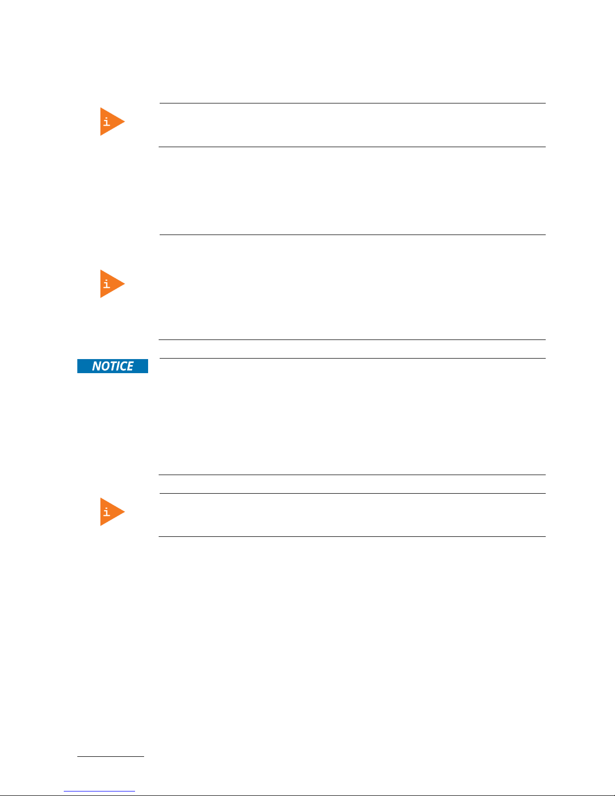
10.1.4. HDMI Connector ................................................................................................................................................................................... 41
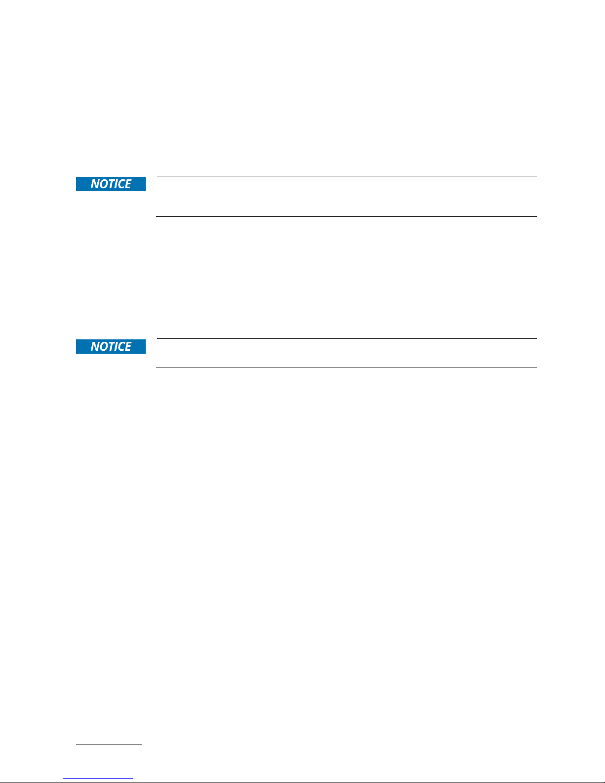
10.1.5. DVI-D Connector ................................................................................................................................................................................... 41
10.1.6. VGA Connector ..................................................................................................................................................................................... 42
10.1.7. RS232/422/485 Serial Port ............................................................................................................................................................. 43
10.1.8. RS232 Serial Port ................................................................................................................................................................................ 43
10.1.9. DIO Port .................................................................................................................................................................................................. 43
10.1.10. Line-Out Connector .......................................................................................................................................................................... 44
10.1.11. Mic-In Connector ................................................................................................................................................................................ 44
11/ uEFI BIOS .............................................................................................................................................................................................. 45
11.1. Starting the uEFI BIOS ............................................................................................................................................................................ 45
11.2. Setup Menus ............................................................................................................................................................................................ 46
11.2.1. Main Setup Menu ................................................................................................................................................................................. 46
11.2.2. Advanced Setup Menu ....................................................................................................................................................................... 48
11.2.3. Power Setup Menu .............................................................................................................................................................................. 61
11.2.4. Boot Setup Menu ................................................................................................................................................................................. 63
11.2.5. Security Setup Menu .......................................................................................................................................................................... 64
11.2.5.1. Remember the password .............................................................................................................................................................. 65
11.2.6. Save & Exit Setup Menu .................................................................................................................................................................... 66
Appendix A: List of Acronyms ..................................................................................................................................................................... 67
About Kontron .................................................................................................................................................................................................. 68
Page 11

RuggedClient-HSW - User Guide, Rev. 1.0
www.kontron.com
// 11
List of Tables
Table 1: Specification for mounting by use of the mounting clamps ............................................................................................. 27
Table 2: Technical Specifications ............................................................................................................................................................... 36
Table 3: Mechanical Specifications ........................................................................................................................................................... 37
Table 4: Environmental Conditions ........................................................................................................................................................... 39
Table 5: Standards and Certifications ...................................................................................................................................................... 39
Table 6: DC Jack (see Figure 2, pos.1) ........................................................................................................................................................ 40
Table 7: Ethernet Connector (see Figure 2, pos. 8) .............................................................................................................................. 40
Table 8: USB 3.0 Port (see Figure 2, pos. 9) ............................................................................................................................................ 40
Table 9: HDMI Connector (see Figure 2, pos. 3) ...................................................................................................................................... 41
Table 10: DVI-D Connector (see Figure 2, pos. 4) ................................................................................................................................... 41
Table 11: VGA Connector (see Figure 2, pos. 5)....................................................................................................................................... 42
Table 12: RS232/422/485 Serial Port (see Figure 2, pos. 10) ........................................................................................................... 43
Table 13: RS232 Serial Port (see Figure 2, pos. 11) ................................................................................................................................ 43
Table 14: DIO Port (see Figure 2, pos. 12) ................................................................................................................................................. 43
Table 15: Line-Out Connector (see Figure 2, pos. 6) ............................................................................................................................. 44
Table 16: Mic-In Connector (see Figure 2, pos. 7) ................................................................................................................................. 44
Table 17: Navigation Hot Keys Available in the Legend Bar............................................................................................................... 45
Table 18: Main Setup Menu Sub-Screens and Functions ................................................................................................................... 46
Table 19: List of Acronyms ............................................................................................................................................................................ 67
List of Figures
Figure 1: Front I/O Panel ................................................................................................................................................................................ 20
Figure 2: Rear I/O Panel .................................................................................................................................................................................. 21
Figure 3: Ethernet LED Status...................................................................................................................................................................... 22
Figure 4: Top I/O Panel .................................................................................................................................................................................. 24
Figure 5: Mounting clamp ............................................................................................................................................................................. 27
Figure 6: Insert the system into the cutout ............................................................................................................................................ 28
Figure 7: Hook mounting clamps into mounting openings ................................................................................................................ 28
Figure 8: VESA mounting hole locations .................................................................................................................................................. 29
Figure 9: Optional VESA mounting kit ....................................................................................................................................................... 30
Figure 10: Secure the base mounting bracket ........................................................................................................................................ 30
Figure 11: Secure the hooked mounting bracket onto the RuggedClient-HSW ........................................................................... 30
Figure 12: Secure the RuggedClient-HSW onto the mounting surface ........................................................................................... 31
Figure 13: Mechanical Drawing ................................................................................................................................................................... 37
Figure 14: BIOS Main Menu Screen System Data and Time ............................................................................................................... 47
Figure 15: BIOS Advanced Menu .................................................................................................................................................................. 49
Figure 16: BIOS Advanced Menu - Display Configuration ................................................................................................................... 50
Figure 17: BIOS Advanced Menu - Super IO Configuration .................................................................................................................. 51
Figure 18: BIOS Advanced Menu - Super IO Configuration - Serial Port 1 Configuration .......................................................... 51
Figure 19: BIOS Advanced Menu - Super IO Configuration - Serial Port 2 Configuration ......................................................... 52
Figure 20: BIOS Advanced Menu - Super IO Configuration - Serial Port 3 Configuration ........................................................ 53
Figure 21: BIOS Advanced Menu - Super IO Configuration - Serial Port 4 Configuration ........................................................ 54
Figure 22: BIOS Advanced Menu - CPU Advanced Configuration .................................................................................................... 55
Figure 23: BIOS Advanced Menu - SATA Configuration ...................................................................................................................... 56
Figure 24: BIOS Advanced Menu - USB Configuration ......................................................................................................................... 57
Figure 25: BIOS Advanced Menu - Intel® Rapid Start Technology .................................................................................................. 58
Figure 26: BIOS Advanced Menu - DIO Configuration .......................................................................................................................... 59
Figure 27: BIOS Advanced Menu - H/W Monitor ................................................................................................................................... 60
Figure 28: BIOS Power Setup Menu ............................................................................................................................................................ 61
Figure 29: BIOS Power Setup Menu - WatchDog Timer Configuration .......................................................................................... 62
Figure 30: BIOS Boot Setup Menu .............................................................................................................................................................. 63
Figure 31: BIOS Security Setup Menu ........................................................................................................................................................ 64
Figure 32: BIOS Save & Exit Setup Menu.................................................................................................................................................. 66
Page 12

RuggedClient-HSW - User Guide, Rev. 1.0
www.kontron.com
// 12
Page 13

RuggedClient-HSW - User Guide, Rev. 1.0
www.kontron.com
// 13
1/ General Safety Instructions for IT Equipment
Please read this chapter carefully and take careful note of the instructions, which have been
compiled for your safety and to ensure to apply in accordance with intended regulations. If
the following general safety instructions are not observed, it could lead to injuries to the
operator and/or damage of the product; in cases of nonobservance of the instructions
Kontron is exempt from accident liability, this also applies during the warranty period.
The product has been built and tested according to the basic safety requirements for low voltage (LVD) applications
and has left the manufacturer in safety-related, flawless condition. To maintain this condition and also to ensure safe
operation, the operator must not only observe the correct operating conditions for the product but also the following
general safety instructions:
The product must be used as specified in the product documentation, in which the instructions for safety for the
product and for the operator are described. These contain guidelines for setting up, installation and assembly,
maintenance, transport or storage.
The on-site electrical installation must meet the requirements of the country's specific local regulations.
If a power cable comes with the product, only this cable should be used. Do not use an extension cable to connect
the product.
To guarantee that sufficient air circulation is available to cool the product, please ensure that the ventilation
openings are not covered or blocked. If an air filter is provided, this should be cleaned regularly. Do not place the
system close to heat sources or damp places. Make sure the system is well ventilated.
Only devices or parts which fulfill the requirements of SELV circuits (Safety Extra Low Voltage) as stipulated by
IEC 60950-1 may be connected to the available interfaces.
Before opening the device, make sure that the device is disconnected from the mains.
Switching off the device by its power button does not disconnect it from the mains. Complete disconnection is
only possible if the power cable is removed from the wall plug or from the device. Ensure that there is free and
easy access to enable disconnection.
The device may only be opened for the insertion or removal of add-on cards (depending on the configuration of
the system). This may only be carried out by qualified operators.
If extensions are being carried out, the following must be observed:
All effective legal regulations and all technical data are adhered to.
The power consumption of any add-on card does not exceed the specified limitations.
The current consumption of the system does not exceed the value stated on the product label.
Only original accessories that have been approved by Kontron can be used.
Please note: safe operation is no longer possible when any of the following applies:
The device has visible damages.
The device is no longer functioning.
In this case the device must be switched off and it must be ensured that the device can no longer be operated.
Page 14

RuggedClient-HSW - User Guide, Rev. 1.0
www.kontron.com
// 14
Additional safety instructions for DC power supply circuits
To guarantee safe operation of devices with DC power supply voltages larger than 60 volts DC or a power
consumption larger than 240 VA, please observe that:
the device is set up, installed and operated in a room or enclosure marked with “RESTRICTED ACCESS”, if
there are no safety messages on product as safety signs and labels on the device itself.
no cables or parts without insulation in electrical circuits with dangerous voltage or power should be
touched directly or indirectly
a reliable protective earthing connection is provided
a suitable, easily accessible disconnecting device is used in the application (e.g. overcurrent protective
device), if the device itself is not disconnectable
a disconnect device, if provided in or as part of the equipment, shall disconnect both poles simultaneously
interconnecting power circuits of different devices cause no electrical hazards
A sufficient dimensioning of the power cable wires must be selected – according to the maximum electrical
specifications on the product label – as stipulated by EN60950-1 or VDE0100 or EN60204 or UL508 regulations.
The devices do not generally fulfill the requirements for "centralized DC power systems“ (UL 60950-1, Annex NAB;
D2) and therefore may not be connected to such devices!
Page 15
RuggedClient-HSW - User Guide, Rev. 1.0
www.kontron.com
// 15
1.1. Electrostatic Discharge (ESD)
A sudden discharge of electrostatic electricity can destroy static-sensitive devices or
micro-circuitry.
Therefore proper packaging and grounding techniques are necessary precautions to prevent damage. Always take the
following precautions:
1. Transport boards in ESD-safe containers such as boxes or bags.
2. Keep electrostatic sensitive parts in their containers until they arrive at the ESD-safe workplace.
3. Always be properly grounded when touching a sensitive board, component, or assembly.
4. Store electrostatic-sensitive boards in protective packaging or on antistatic mats.
1.1.1. Grounding Methods
By adhering to the guidelines below, electrostatic damage to the device can be avoided:
1. Cover workstations with approved antistatic material. Always wear a wrist strap connected to workplace. Always
use properly grounded tools and equipment.
2. Use antistatic mats, heel straps, or air ionizers for more protection.
3. Always handle electrostatically sensitive components by their edge or by their casing.
4. Avoid contact with pins, leads, or circuitry.
5. Turn off power and input signals before inserting and removing connectors or connecting test equipment.
6. Keep work area free of non-conductive materials such as ordinary plastic assembly aids and Styrofoam.
7. Use only field service tools which are conductive, such as cutters, screwdrivers, and vacuum cleaners.
8. Always place drives and boards PCB-assembly-side down on the foam.
1.2. Lithium Battery Replacement
If replacing the lithium battery, follow the replacement precautions stated below.
Danger of explosion when replacing with wrong type of battery. Replace only with the
same or equivalent type recommended by the manufacturer. The lithium battery type
must be UL recognized.
Do not dispose of lithium batteries in general trash collection. Dispose of the battery
according to the local regulations dealing with the disposal of these special materials,
(e.g. to the collecting points for dispose of batteries).
Page 16

RuggedClient-HSW - User Guide, Rev. 1.0
www.kontron.com
// 16
2/ Electromagnetic Compatibility
For detailed information refer to section 9.3 “Standards and Certifications”.
2.1. Electromagnetic Compatibility (EU)
This product is intended only for use in industrial areas. The most recent version of the EMC guidelines (EMC Directive
2004/108/EC) apply. If the user modifies and/or adds to the equipment (e.g. installation of add-on cards) the
prerequisites for the CE conformity declaration (safety requirements) may no longer apply.
This is a class A product. In domestic environment this product may cause radio
interference in which case the user may be required to take adequate measures.
2.2. FCC Statement (USA)
This equipment has been tested and found to comply with the limits for a Class A digital device, pursuant to Part 15 of
the FCC Rules. These limits are designed to provide reasonable protection against harmful interference when the
equipment is operated in commercial environment. This equipment generates, uses, and can radiate radio frequency
energy and, if not installed and used in accordance with the instruction manual, may cause harmful interference to
radio communications. Operation of this equipment in residential area is likely to cause harmful interference in which
case the user will be required to correct the interference at his own expense.
2.3. EMC Compliance (Canada)
The method of compliance is self-declaration to Canadian standard ICES-003:
(English): This Class A digital apparatus complies with the Canadian ICES-003.
(French): Cet appareil numérique de la class A est conforme à la norme NMB-003 du Canada.
Page 17

RuggedClient-HSW - User Guide, Rev. 1.0
www.kontron.com
// 17
3/ Shipment and Unpacking
Please check that your package is complete, and contains the items below (according to the ordered unit
configuration). If you discover damaged or missing items, please contact your dealer.
3.1. Unpacking
Proceed as follows to unpack the unit:
1. Remove packaging.
2. Do not discard the original packaging. Keep it for future relocation.
3. Check the delivery for completeness by comparing it with your order.
4. Please keep the associated paperwork. It contains important information for handling the unit.
5. Check the contents for visible shipping damage.
6. If you notice any shipping damage or inconsistencies between the contents and your order, please contact
Kontron for help and information.
3.2. Scope of Delivery
3.2.1. Standard
1x RuggedClient-HSW (corresponding to the ordered system configuration)
1x Power adapter
1x Power cord
3.2.2. Optional Parts
Memory module(s)
Internal 2.5" SATA HDD / SSD
mPCIe card(s)
Antenna(s)
VESA mounting kit
Page 18

RuggedClient-HSW - User Guide, Rev. 1.0
www.kontron.com
// 18
4/ System Overview
Kontron RuggedClient-HSW integrates an industrial PC with an integrated touch screen display. The rugged design
offers excellent mechanical stability for operation in harsh industrial environments.
It can be optionally factory-equipped with an mPCIe WLAN card and / or an mPCIe 3G / 4G card as well as antennas.
Users may choose the implementation of a 2.5" SATA HDD / SSD as storage media.
The following interfaces are available with the RuggedClient-HSW:
Standard Front Panel:
1x Power LED
Standard Rear Panel:
1x HDMI
1x DVI-D
1x VGA
1x Line-out
1x Mic-in
2x GbE LAN
4x USB 3.0
2x RS232/422/485
2x RS232
1x DIO
1x DC 12 V Power Jack
1x Power Switch
Standard Baseboard and System Expansion Capabilities:
2x 204-pin DDR3L SO-DIMM memory socket (DIMM1 & DIMM2 socket)
1x SATA connector (SATA1, 2, 3, 4, 5, or 6 connector) for 2.5" SATA HDD / SSD
1x full-sized mPCIe socket (MPCIE1 socket) for mPCIe expansion card
1x half-sized mPCIe socket (MPCIE2 socket) for mPCIe expansion card
The device is designed to be operated in:
Vertical position: mounted in an instrument / wall / other cabinet (with the corresponding supplied mounting
clamps) or on the wall / VESA stand / VESA pole (with a VESA mounting kit)
When powering on the RuggedClient-HSW, make sure that the air intake and exhaust
openings of the chassis are not obstructed (covered) by any objects.
To provide sufficient heat dissipation by the cooling of the device, do not cover the air intake
and exhaust openings of the RuggedClient-HSW. When installing the system, please keep
clearance for air circulation.
4.1. System Expansion Capabilities
4.1.1. System Expansion via SATA Interface
The system reserves space allowing users to expand the RuggedClient-HSW with a 2.5" SATA HDD / SSD drive via one
of the onboard SATA interface connectors.
Page 19

RuggedClient-HSW - User Guide, Rev. 1.0
www.kontron.com
// 19
4.1.2. System Expansion via mPCIe Card Interface
The baseboard comes with an onboard full-sized mPCIe interface connector and an onboard half-sized mPCIe
interface connector. The connectors are intended to be used to install an mPCIe WLAN card.
If a customer requires 3G / 4G functionality, it must be so stipulated when ordering, as
an optional SIM card slot must be installed at the factory.
3G / 4G modem adapter card (and SIM card) is functional only with the half-sized
mPCIe interface connector.
Page 20
RuggedClient-HSW - User Guide, Rev. 1.0
www.kontron.com
// 20
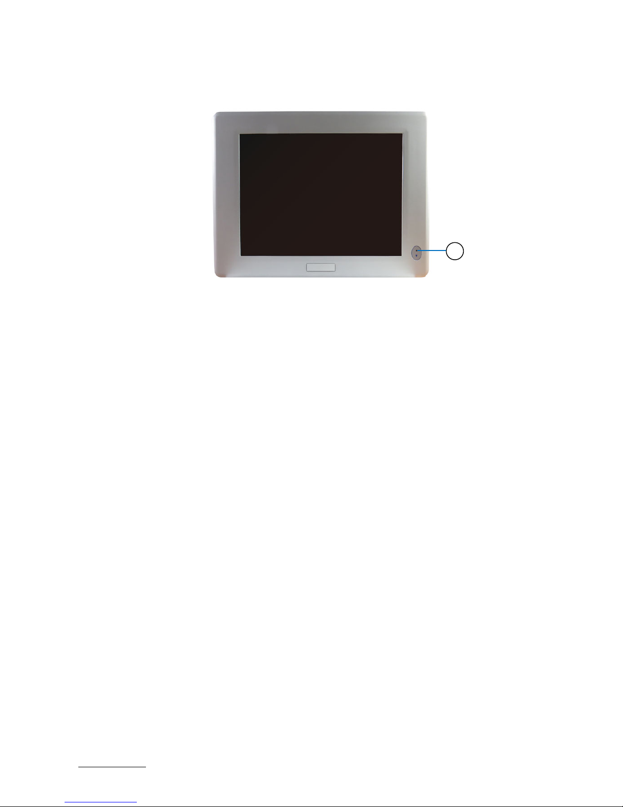
4.2. Front I/O Panel
Figure 1: Front I/O Panel
1 Power LED (see Chapter 4.2.1)
4.2.1. Power LDE
The power LED lights up if the system is powered on.
Prerequisite: The system must be attached by means of the power cord to an appropriate mains (DC).
1
Page 21

RuggedClient-HSW - User Guide, Rev. 1.0
www.kontron.com
// 21
4.3. Rear I/O Panel
Figure 2: Rear I/O Panel
1 2.5 mm jack DC-In Power Connector (see Chapter 4.3.1)
2 Power Switch (see Chapter 4.3.2)
3 HDMI (see Chapter 4.3.3)
4 DVI-D (see Chapter 4.3.4)
5 VGA (see Chapter 4.3.5)
6 Line-Out (see Chapter 4.3.6)
7 Mic-In (see Chapter 4.3.7)
8 GbE (see Chapter 4.3.8)
9 USB 3.0 (see Chapter 4.3.9)
10 RS232/422/485 (see Chapter 4.3.10)
11 RS232 (see Chapter 4.3.11)
12 DIO (see Chapter 4.3.12)
4.3.1. 2.5 mm Jack DC-In Power Connector
The supplied power adapter converts AC power to DC for use with this jack with 2.5 mm inside contact diameter.
Power supplied through this jack supplies power to the PC. To prevent damage to the PC, always use the supplied
power adapter.
4.3.2. Power Switch
Press this switch to turn the system on or off.
Even when the system is turned off via the power switch there is still a standby voltage on
the baseboard. The unit is only completely disconnected from the power supply, when the
power is removed.
1
2 5
4
6 8 8
7 3 10
10
9 9 9
9
11 11
12
Page 22
RuggedClient-HSW - User Guide, Rev. 1.0
www.kontron.com
// 22
4.3.3. HDMI
The RuggedClient-HSW provides one HDMI connector. One external (digital) display can be connected to this HDMI
connector.
4.3.4. DVI-D
The RuggedClient-HSW provides one DVI-D (Digital Video Interface Digital) connector. One external (digital) display
can be connected to this DVI-D connector.
4.3.5. VGA
An external (analog) monitor can be plugged into this interface. The VGA port is provided as a 15-pin D-SUB socket.
VGA Hot Plug works on Windows and Linux installation which have an appropriate driver
installed. However, VGA Hot Plug does not work on the EFI shell, DOS or BIOS Setup.
Hot Removal and Re-Connect of a VGA display always works on BIOS Setup, EFI shell, DOS
regardless of the OS Version, provided the VGA display is connected during power up of the
RuggedClient.
4.3.6. Line-Out
The stereo headphone jack is used to connect the system’s audio out signal to amplified speakers or headphones.
4.3.7. Mic-In
The microphone jack is designed to connect the microphone used for video conferencing, voice narrations, or simple
audio recordings.
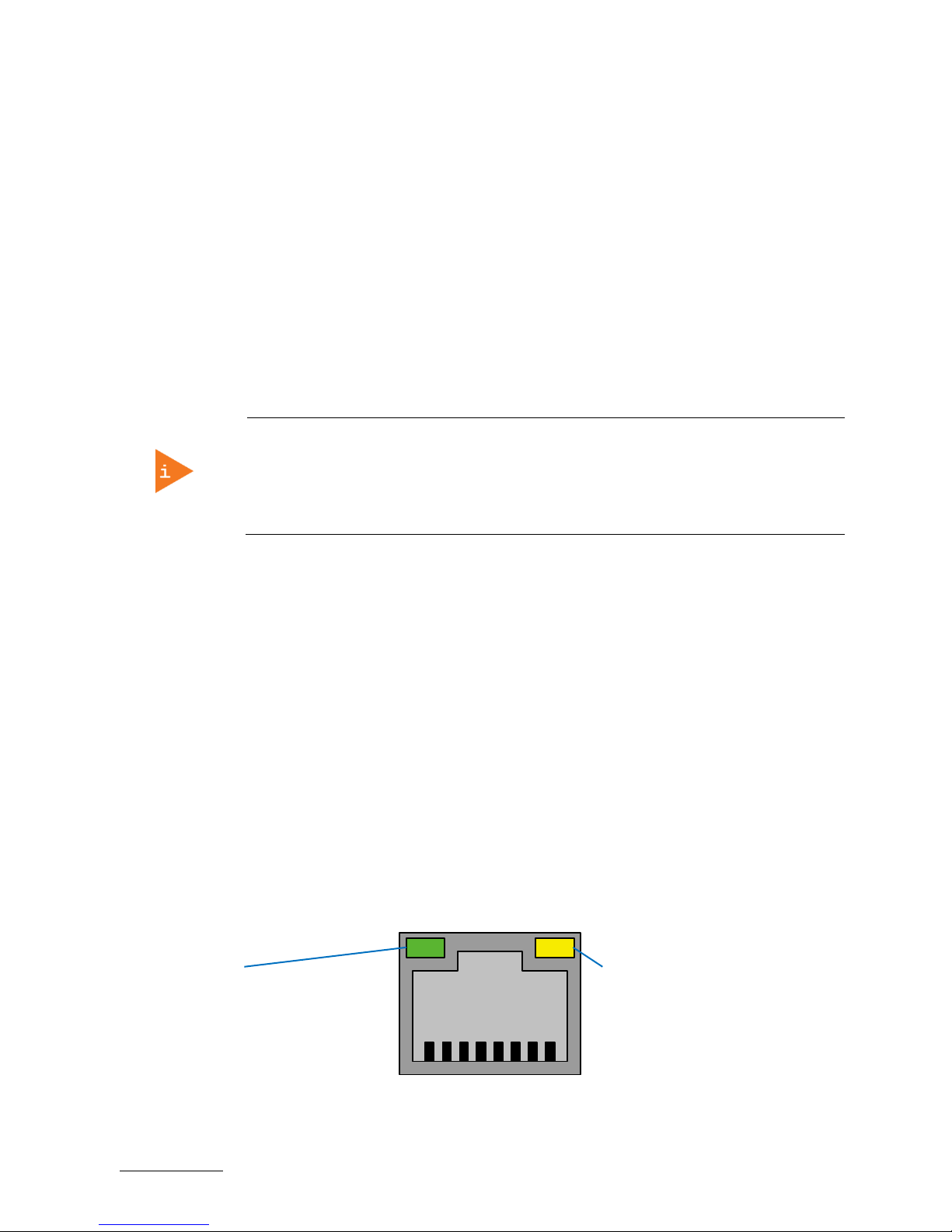
4.3.8. GbE
These connectors are Gigabit Ethernet 10/100/1000 Mbit/s, IEEE 1588 capable interfaces. The connectors are
standard 8-pin RJ45 type connectors with status LEDs:
Figure 3: Ethernet LED Status
LED satatus:
Orange - 1000 Mbit/s link established
Green - 100 Mbit/s link established
Off - 10 Mbit/s link established
LED satatus:
Off - Link is down
Flashing Green - Link is up and active
Steady Green - Link is up, no activity
Page 23

RuggedClient-HSW - User Guide, Rev. 1.0
www.kontron.com
// 23
4.3.9. USB 3.0
The RuggedClient-HSW provides four USB 3.0 / 2.0 interface. These connectors allow connection of USB 3.0 or USB
2.0 compatible device to the system.
4.3.10. RS232/422/485
COM 1 and COM 2 are provided as a 9-pin D-SUB connector and allow the connection of a serial peripheral. They are
designed to support RS232/422/485 serial communication which can be configured via BIOS setup.
4.3.11. RS232
COM 3 and COM 4 are provided as a 9-pin D-SUB connector and allow the connection of a serial peripheral. They are
designed to support RS232 serial communication.
4.3.12. DIO
The RuggedClient-HSW provides one 9-pin female D-SUB connector and allow the connection of digital signals for
input and output purposes.
Page 24

RuggedClient-HSW - User Guide, Rev. 1.0
www.kontron.com
// 24
4.4. Top I/O Panel
Figure 4: Top I/O Panel
1 Antenna Port (see Chapter 4.4.1)
4.4.1. Antenna
The RuggedClient-HSW reserves two covered cutouts for the Reverse Polarity (RP) SMA connectors of two WLAN
antennas (mPCIe WLAN card with two antennas is an option).
1 1
Page 25

RuggedClient-HSW - User Guide, Rev. 1.0
www.kontron.com
// 25
5/ Thermal Considerations
5.1. Available Processors
Please refer to the chapter 9/ "Technical Specifications".
The list of processors may be extended over the product lifetime.
5.2. Convection Cooling
The applied cooling method provides adequate cooling of the device during operation. The air intakes and exhaust
openings located on the rear and three sides of the chassis provide air circulation for the system interior cooling, in
order to prevent overheating.
To provide sufficient heat dissipation for the cooling of the RuggedClient-HSW, never
cover the air openings of the chassis.
5.3. System Clearance
To provide a maximum of airflow through the rear side of the device, proper distances to the rear side must be
observed.
5.4. Maximum Temperatures
The maximum system ambient temperature depends mostly on the power consumption
of the processor and the chipset.
For the temperature evaluation a specialised tool from Intel® was used to set the processor to a defined workload.
Depending on the power consumption one or more cores were set to 75% workload. This includes the graphics core.
The tool also handles the usage of the "Turbo Mode" of certain processor types.
The processor utilization depends highly on the software used. Software using
multicore feature will run on several cores whereas standard software will only utilize
one core. In this case the processor will use the "Turbo Mode" to increase the clock for
the core with the highest workload, as long as the temperature is within limits.
5.5. Third Party Components
When the RuggedClient-HSW is extended and configured with third party components like mPCIe expansion card and
hard drives (HDD or SSD), it has to be taken into account that the air temperature inside the system is higher than the
ambient temperature. An approximately internal temperature rise is given for assistance.
Page 26

RuggedClient-HSW - User Guide, Rev. 1.0
www.kontron.com
// 26
6/ Installation Instructions
The RuggedClient-HSW system is designed for operating:
in an instrument / wall / other cabinet by use of the corresponding supplied mounting clamps
onto a wall / VESA stand / VESA pole by use of a VESA mounting kit.
Whenever possible, unpack or pack this product only at EOS/ESD safe work stations.
Where a safe work station is not guaranteed, it is important for the user to be
electrically discharged before touching the product with his/her hands or tools. This is
most easily done by touching a metal part of the system chassis.
Do not handle this product out of its protective enclosure while it is not used for
operational purposes unless it is otherwise protected.
Prior any installation work, ensure that there are no live wires on the installation site.
Do not handle the device if there is any damage visible.
Do not operate the RuggedClient-HSW with foreign objects inside the chassis.
Further do not insert any retrieval device into the device while it is connected to power.
Kontron rejects all liability for any and all damages resulting from operation of the unit
with foreign objects inside the chassis.
The RuggedClient-HSW has to be installed and operated only by trained and qualified
personnel.
Only personnel with appropriate qualifications, trainings and authorization are
permitted to install and work with the Kontron RuggedClient-HSW.
This device shall only be installed in or connected to systems that fulfill all necessary
technical and specific environmental requirements.
The unit must be placed such that there is sufficient space in rear of it for connecting
the cables to the I/O interface connectors and for operating the power button.
Leave sufficient free space around the unit to prevent the device from possibly
overheating!
The RuggedClient-HSW must be firmly attached to a clean flat and solid mounting
surface. Use proper fastening materials suitable for the mounting surface. Ensure that
the mounting surface type and the used mounting solution safely support the load of
the RuggedClient-HSW and the attached components.
Please follow the local/national regulations for grounding.
The voltage feeds must not be overloaded. Adjust the cabling and the overcurrent
protection to correspond with the electrical figures indicated on the type label.
The type label is located on the rear side of the system.
It is recommended that the last cable attached to the system should be the power
cable! Refer to the section 6.2 “DC Power Connection” and chapter 7/ “Starting Up”.
Page 27
RuggedClient-HSW - User Guide, Rev. 1.0
www.kontron.com
// 27
6.1. System Mounting
In order to adapt the RuggedClient-HSW for mounting Kontron offers different mounting solution such as:
Panel mount: RuggedClient-HSW configuration with the corresponding supplied mounting clamps for vertical
installation into an instrument / wall / other cabinet
VESA mount: RuggedClient-HSW configuration with a VESA mounting kit for vertical installation onto a wall /
VESA stand / VESA pole
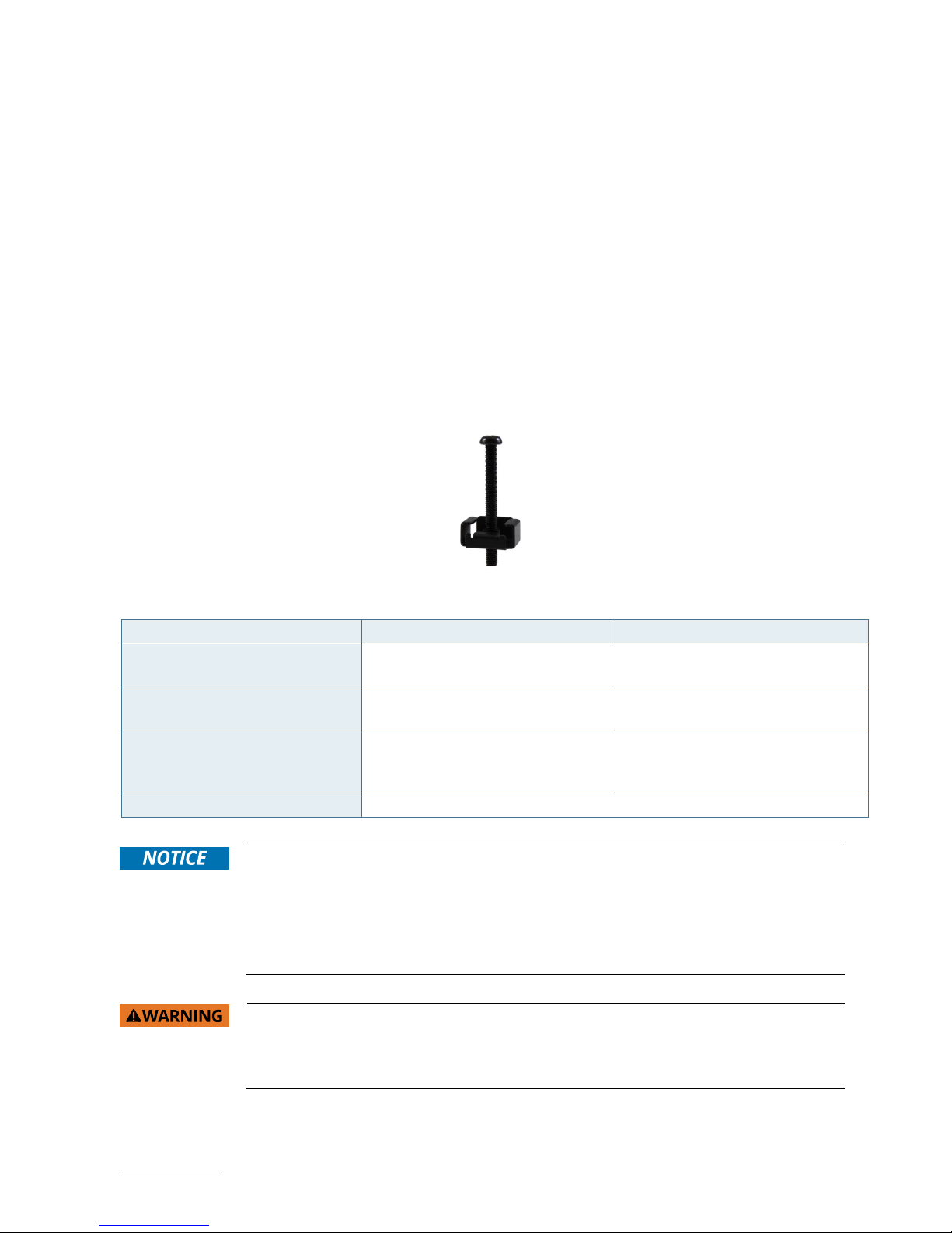
6.1.1. System Mounting by Use of the Mounting Clamps
Depending on the ordered RuggedClient-HSW configuration, your system is supplied with a number of the
corresponding mounting clamps (Figure 6) sufficient to mount the system into an instrument / wall / other cabinet.
Figure 5: Mounting clamp
Table 1: Specification for mounting by use of the mounting clamps
Model 15" Model 17" Model
Cut-out for mounting to a wall /
panel (W x H) [mm]
381 x 293 mm
(15" x 11.54")
408.7 x 332.2 mm
(16.09" x 13.08")
Thickness for the mounting wall /
panel for proper mounting [mm]
1.5 ~ 6
Number of the clamps with screws
for mounting to a wall / panel
9
(3 for top side, 2 for bottom / right /
left side)
11
(3 for top /right / left side, 2 for
bottom side)
Required tool Phillips screwdriver
In order to ensure IP65 front sealing against dust and water,
mount the system on a non-
textured surface
.
Before you install the RuggedClient-HSW into a panel or a wall, verify the perfect condition
of the gasket at the rear of the front bezel.
The gasket has to be in place without surface imperfections / defects and dirt.
Ensure the vertical and horizontal alignment of the system.
The screen of the RuggedClient-HSW is fragile. Handle with care to prevent personal injury
or material damage. Always use two hands when carrying the device.
The screen of the RuggedClient-HSW is provided with a protective film. Only remove this
protective material after the installation of the RuggedClient-HSW.
To mount the system to a wall or to a panel, please proceed according to the steps described:
Page 28

RuggedClient-HSW - User Guide, Rev. 1.0
www.kontron.com
// 28
1. Depending on the dimension of your RuggedClient-HSW, prepare a cutout in the wall / panel. The maximum
thickness of the wall / panel is 6 mm. Refer to Table 1 and Figure 6 for the wall / panel cutout dimensions or to
Figure 14 for the corresponding mechanical drawings of your RuggedClient-HSW.
2. The system must be properly powered down and disconnected from the power source and peripherals.
3. The wall / panel where you intend to install the system must be accessible from both sides (front as well as
rear). The material strength and stiffness must be sufficient to hold the system unit.
4. Insert the system into the wall / panel cutout front the front as shown in Figure 6.
Figure 6: Insert the system into the cutout
5. In order to ensure the protection class IP65 on the front side in the installed condition, the contact surface with
the gasket must be clean and flush.
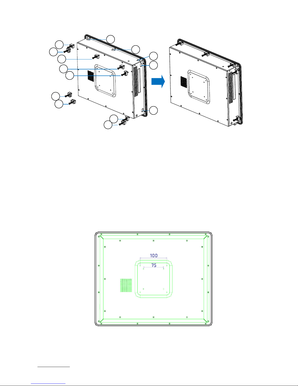
6. Remove the mounting opening covers from the chassis with Phillips screwdriver. The number of mounting
openings (Table 1) varies depending on the ordered RuggedClient-HSW configuration.
7. Hook the mounting clamps with screws (Figure 5) from the rear side of the wall / panel into the corresponding
mounting openings as shown in Figure 7.
Figure 7: Hook mounting clamps into mounting openings
Page 29
RuggedClient-HSW - User Guide, Rev. 1.0
www.kontron.com
// 29
1 Mounting Clamp with Screw
2 Mounting Opening with Cover (Remove the cover before hooking the mounting clamp into it.)
8. The system must be attached firmly by tightening the screws. Always tighten screws on the opposite side of the
front panel.
6.1.2. System Mounting by Use of a VESA Mounting Kit
The Ruggedclient-HSW comes with VESA FDMI 75 / 100 standard mounting holes (Figure 8).
Figure 8: VESA mounting hole locations
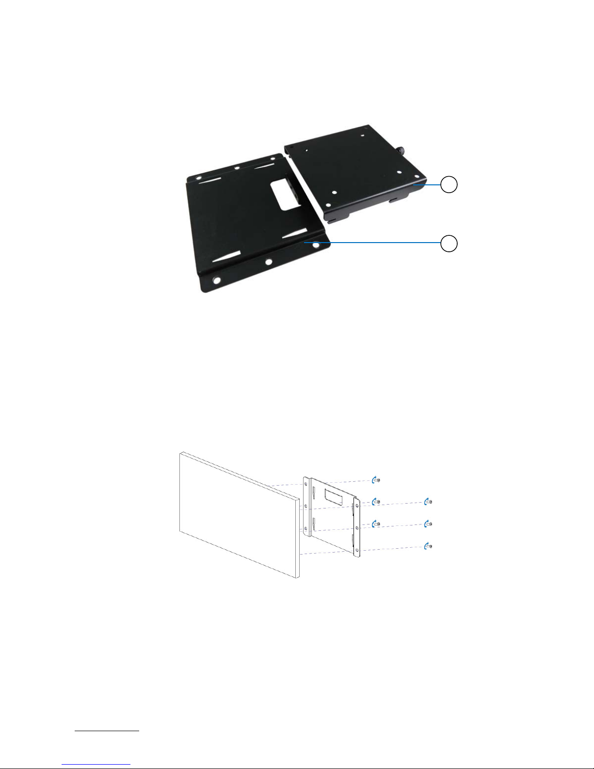
Depending on the ordered RuggedClient-HSW configuration, your system may be supplied with a VESA mounting kit
(Figure 9). The kit consists of two parts: a base bracket (Figure 9, pos. 1) to be fixed permanently on the mounting
1
1
1
1
1
1
1
1
1
2
2
2
2
2
Page 30
RuggedClient-HSW - User Guide, Rev. 1.0
www.kontron.com
// 30
surface and another hooked bracket to hold the RuggedClient-HSW with a hand-screw knob (Figure 9, pos. 2) to
secure two brackets.
Figure 9: Optional VESA mounting kit
1 Base mounting bracket
2 Hooked mounting bracket with a hand-screw knob
To mount the RuggedClient-HSW please proceed according to the steps described:
1. Prepare the mounting surface with sufficient screws (six screws for base mounting bracket) and if necessary
anchors corresponding to the mounting surface type if no screw holes are available.
2. Secure the base mounting bracket to the mounting surface with screws (Figure 10).
Figure 10: Secure the base mounting bracket
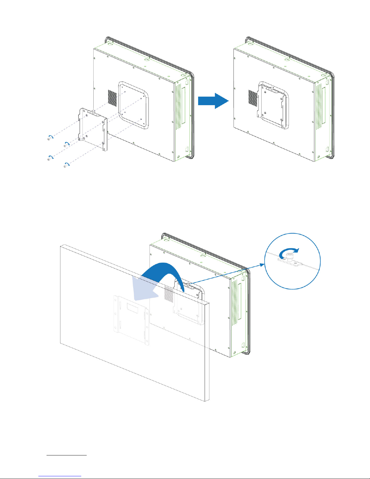
3. Secure the hooked mounting bracket onto the rear side of the RuggedClient-HSW (Figure 11).
Figure 11: Secure the hooked mounting bracket onto the RuggedClient-HSW
2
1
Page 31
RuggedClient-HSW - User Guide, Rev. 1.0
www.kontron.com
// 31
4. Place the RuggedClient-HSW onto the mounting surface by sliding the hooked mounting bracket into the based
mounting bracket (Figure 12).
5. Secure the hand-screw knob located on the hooked mounting bracket to fix two brackets (Figure 12).
Figure 12: Secure the RuggedClient-HSW onto the mounting surface
Page 32

RuggedClient-HSW - User Guide, Rev. 1.0
www.kontron.com
// 32
6.2. DC Power Connection
The RuggedClient-HSW is connected by a DC power input jack (Figure 2, pos. 1) to a DC power source.
The RuggedClient-HSW is delivered with a power adapter to convert AC voltage into DC 12 V and a power cord to carry
AC power to the power adapter.
Page 33
RuggedClient-HSW - User Guide, Rev. 1.0
www.kontron.com
// 33
7/ Starting Up
The RuggedClient-HSW must be only operated with the nominal voltage of 12V DC of
type SELV. For details refer to the chapter 9/ “Technical Specifications”.
7.1. Connecting to DC Power Supply
The DC power input jack (Figure 2, pos. 1) is located on the rear side of the RuggedClient-HSW. The RuggedClient-HSW
will be connected to a AC-to-DC power adapter via the supplied male DC power plug and corresponding power cable
attached to the adapter.
Before u
sing your system, become familiar with the system components and check that
everything is connected properly. Following a proper cabling procedure will prevent a
false power-on condition, which could result in unit operational failure.
When you install/disconnect the unit, the functional earth connection must always be
made first and disconnected last.
Also, it is recommended that the last connections attached to the system should be the
power wires!
The RuggedClient-HSW must be connected DC power supply complying with the SELV
(Safety Extra Low Voltage) requirements of EN 60950-1 standard. It must be observed
that wiring and short-circuit/overcurrent protection is performed according to the
applicable standards, regulations and respect to the electrical specification of the
RuggedClient-HSW.
Even when the system is turned off via the power switch (Figure 2, pos. 2) parts of the
system are still energized.
The disconnecting device (fuse/circuit backer) rating must be in accordance with the
wire cross-section and the rated current of the RuggedClient-HSW.
The cables must have some form of support so as to minimize the strain on the unit’s
connectors.
To connect the RuggedClient-HSW to a corresponding DC power supply, please perform the following steps:
1. Connect the power adapter cable to the DC jack (DC IN, Figure 2, pos. 1) of the RuggedClient-HSW.
2. Connect the power cable to the power adapter.
3. Connect the power cable to a power outlet.
4. Press the power switch (Figure 2, pos. 2) on the rear panel to turn on the system.
Page 34

RuggedClient-HSW - User Guide, Rev. 1.0
www.kontron.com
// 34
7.2. Operating System and Hardware Component Drivers
Your system can be supplied optionally with a pre-installed operating system.
If you have ordered your RuggedClient-HSW with a pre-installed operating system, all drivers are installed in
accordance with the system configuration ordered (optional hardware components). Your system is fully operational
when you switch it on for the first time. Please pay attention to the following note.
Important information on the use of the pre-installed “WINDOWS 7 ULTIMATE FOR
EMBEDDED SYSTEMS” or “WINDOWS 7 PROFESSIONAL FOR EMBEDDED
SYSTEMS“ operating systems:
The terms and conditions for the use of the pre-installed operating systems are
specified in the document “MICROSOFT SOFTWARE LICENSE TERMS”.
You can download this document from our web site www.kontron.com by selecting
Product/ Downloads tab/Windows.
If you have ordered the RuggedClient-HSW without a pre-installed operating system, you will need to install the
operating system and the appropriate drivers for the system configuration you have ordered (optional hardware
components) yourself.
You can download the relevant drivers for the installed hardware from our web site at
www.kontron.com by selecting the product.
Pay attention to the manufacturer specifications of the operating system and the
integrated hardware components.
Latest Linux Distribution and Kernel shall be used in order to properly support the
Haswell graphics engine.
Page 35
RuggedClient-HSW - User Guide, Rev. 1.0
www.kontron.com
// 35
8/ Maintenance and Cleaning
Kontron systems require minimal maintenance and care to keep operation correctly.
Occasionally wipe the RuggedClient with a soft dry microfiber cloth.
You should only remove persistent dirt by use of a soft, slightly damp cloth and mild detergent.
8.1. Touch Screen Care and Cleaning
The touch screen is covered by an anti-glare surface finish and care should be taken
when cleaning it. The front side of the touch display unit is sealed against dust and
liquids.
The touch screen is protected by an anti-glare surface finish. Care should be taken to avoid using sharp objects such
as knife, pen or pencil tips. Sharp objects may permanently damage the surface of the anti-glare surface finish.
Mild detergent and water is recommended for cleaning the touch screen. Use of strong solvents must be avoided.
Wet the display surface with a microfiber cloth lightly moistened with warm water and mild glass cleaner.
8.2. Replacing the Lithium Battery
The lithium battery is located on the baseboard and is not a serviceable part. Please
contact Kontron support if the lithium battery needs to be replaced.
Page 36

RuggedClient-HSW - User Guide, Rev. 1.0
www.kontron.com
// 36
9/ Technical Specifications
Table 2: Technical Specifications
System
Processor 4th Generation Intel® Core™ i / Celeron® Processors (FCPGA946 Socket)
Chipset Intel® HM87 / QM87
Memory 2x DDR3L SO-DIMM memory socket
Video
Display
Size 15" 17"
Ratio 4:3 5:4
Backlight LED LED
Resolution 1024 x 768 XGA 1280 x 1024 SXGA
Touch 5-wire Resistive 5-wire Resistive
Display Interface 1x HDMI (on rear)
1x DVI-D (on rear)
1x VGA (on rear)
Multiple Display Triple
Audio
Audio Codec Realtek ALC662
Audio Interface
2x Speaker-out (3W)
1x Line-out (on rear)
1x Mic-in (on rear)
Network Connection
Ethernet 2x GbE LAN (RJ45 on rear, 1x Intel® I217-LM, 1x Intel® I210-AT)
Peripheral Connection
USB 4x USB 3.0 (Type A on rear)
Serial Port
2x RS232/422/485 (DB9 on rear)
2x RS232 (DB9 on rear)
Other I/Os 1x DIO (DB9 Female on rear)
Storage & Expansion
Storage &
Expansion
1x 2.5" SATA HDD / SSD
2x mPCIe (1x full size, 1x half size)
1x SIM Card Cage (optional)
Power
Input Voltage DC 12 V
Connector Lockable DC jack
Power Adapter AC 100 V ~ 240 V
Firmware
BIOS AMI uEFI BIOS w/ 128 Mb SPI Flash
Watchdog Programmable WDT to generate system reset event
H/W Monitor Voltages, Temperatures
Real Time Clock Chipset integrated RTC
System Control & Monitoring
Page 37

RuggedClient-HSW - User Guide, Rev. 1.0
www.kontron.com
// 37
Button, Switch &
Indicator
1x Power Switch (on rear)
1x Power LED (on front)
Cooling
Cooling Method Active
Software
OS Support Windows 7, Windows 8, Linux
9.1. Mechanical Specifications
Table 3: Mechanical Specifications
Construction Metal Chassis + Aluminum Front Bezel
Dimensions (W x H x D) 410 mm x 315 mm x 82.46 mm
(16.14” x 12.40” x 3.25”)
442 mm x 354 mm x 93.44 mm
(17.40” x 13.94” x 3.68”)
Weight 6.8 kg (14.99 lb) TBD
Mounting Panel Mount, VESA Mount
9.1.1. Mechanical Drawing
Figure 13: Mechanical Drawing
15" Model
17" Model
Page 38

RuggedClient-HSW - User Guide, Rev. 1.0
www.kontron.com
// 38
(unit: mm)
Page 39

RuggedClient-HSW - User Guide, Rev. 1.0
www.kontron.com
// 39
9.2. Environmental Conditions
Table 4: Environmental Conditions
Operating Temperature 0 °C ~ 50 °C / 32 °F ~ 122 °F
Storage Temperature -20 °C ~ 70 °C / -4 °F ~ 158 °F
Humidity 0 % ~ 95 %
9.3. Standards and Certifications
Table 5: Standards and Certifications
CE
EN 55022: 2010 + AC: 2011 and CISPR 22: 2008 (modified)
AS/NZS CISPR 22: 2009 with Amdt 1 (2010) (CISPR 22 Ed. 6.0)
EN 61000-3-2: 2014 and IEC 61000-3-2: 2014
EN 61000-3-3: 2013 and IEC 61000-3-3: 2013
EN 55024: 2010 + A1: 2015 and CISPR 24: 2010 + A1: 2015
EN 61000-4-2: 2009 and IEC 61000-4-2: 2008
EN 61000-4-3: 2006 + A1: 2008 + A2: 2010 and IEC 61000-4-
3: 2006 + A1: 2007 +
A2: 2010
EN 61000-4-4: 2012 and IEC 61000-4-4: 2012
EN 61000-4-5: 2014 and IEC 61000-4-5: 2014
EN 61000-4-6: 2014 + AC: 2015 and IEC 61000-4-6: 2013
EN 61000-4-8: 2010 and IEC 61000-4-8: 2009
EN 61000-4-11: 2004 and IEC 61000-4-11: 2004
FCC
FCC CFR Title 47 Part 15 Subpart B: 2015 - Section 15.107 and 15.109
ANSI C63.4-2014
ICES-003 Issue 6: 2016 Class A
Page 40

RuggedClient-HSW - User Guide, Rev. 1.0
www.kontron.com
// 40
10/ Standard Interfaces – Pin Assignments
Low-active signals are indicated by a minus sign.
10.1.1. DC Jack
Table 6: DC Jack (see Figure 2, pos.1)
Pin Signal Name DC Jack (female)
1 +12Vin
2 GND
10.1.2. Ethernet Connectors
Table 7: Ethernet Connector (see Figure 2, pos. 8)
Pin Signal Name LAN1, LAN2 (RJ45)
1 TX1+
8 7 6 5 4 3 2 1
2 TX1-
3 TX2+
4 TX3+
5 TX3-
6 TX2-
7 TX4+
8 TX4-
10.1.3. USB 3.0 Port
Table 8: USB 3.0 Port (see Figure 2, pos. 9)
USB 2.0 Contact Pins USB 3.0 Contact Pins 9-pin USB Connector Type A Version 3.0 / 2.0
Pin Signal Name Pin Signal Name
1 +USBVCC 5 USB_RX-
2 USB_D- 6 USB_RX+
3 USB_D+ 7 GND
4 GND 8 USB_TX-
9 USB_TX+
Page 41
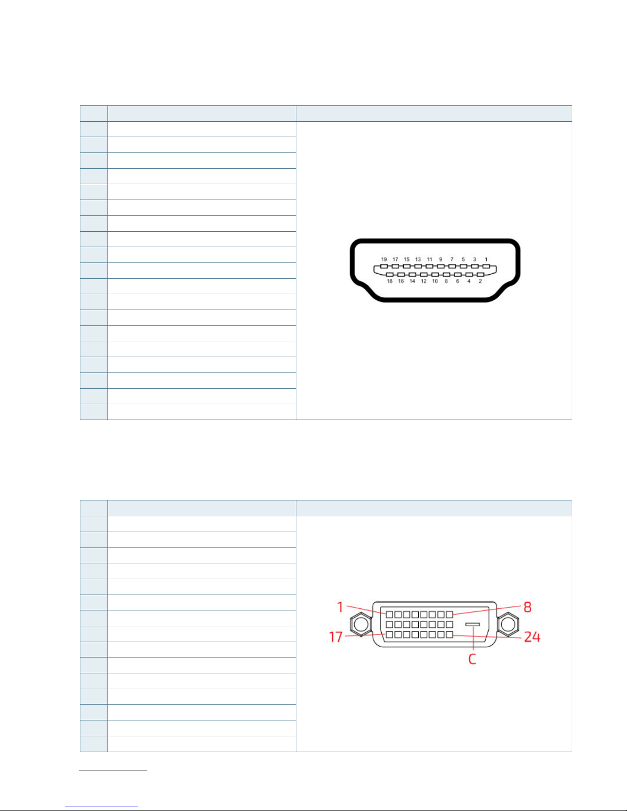
RuggedClient-HSW - User Guide, Rev. 1.0
www.kontron.com
// 41
10.1.4. HDMI Connector
Table 9: HDMI Connector (see Figure 2, pos. 3)
Pin Signal Name HDMI Connector Type A Version 1.4
1 TMDS Data2+
2 Ground
3 TMDS Data2–
4 TMDS Data1+
5 Ground
6 TMDS Data1–
7 TMDS Data0+
8 Ground
9 TMDS Data0–
10 TMDS Clock+
11 Ground
12 TMDS Clock–
13 Reserved
14 Reserved
15 DDC_CLK
16 DDC_DATA
17 Ground
18 +5 V Power
19 Hot Plug Detect
10.1.5. DVI-D Connector
Table 10: DVI-D Connector (see Figure 2, pos. 4)
Pin Signal Name DVI-D Connector 24+1-pin Female Connector
1 TX2-
2 TX2+
3 GND
4 NC
5 NC
6 DDC_CLK
7 DDC_DATA
8 NC
9 TX1-
10 TX1+
11 GND
12 NC
13 NC
14 +5V
15 GND
Page 42
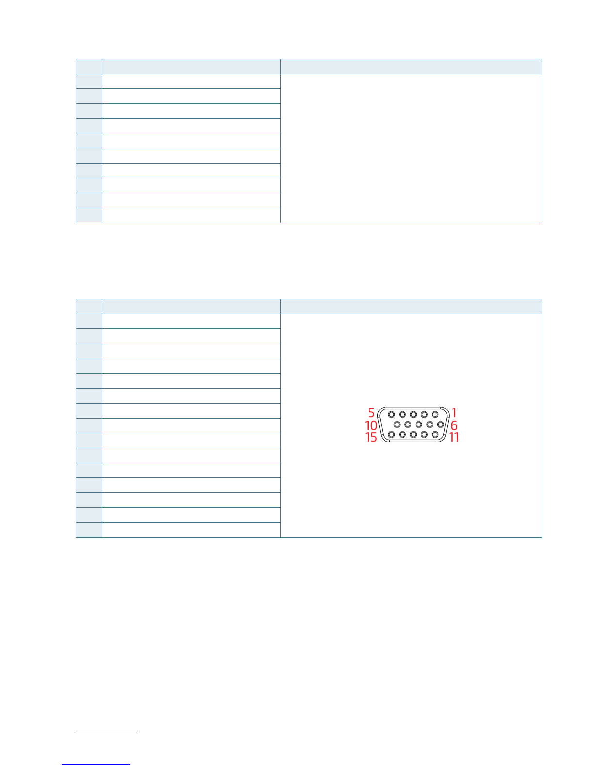
RuggedClient-HSW - User Guide, Rev. 1.0
www.kontron.com
// 42
Pin Signal Name DVI-D Connector 24+1-pin Female Connector
16 HT PLG
17 TX0-
18 TX0+
19 GND
20 NC
21 NC
22 GND
23 TXC+
24 TXC-
C GND
10.1.6. VGA Connector
Table 11: VGA Connector (see Figure 2, pos. 5)
Pin Signal Name 15-pin D-SUB Female Connector
1 Red
2 Green
3 Blue
4 NC
5 GND
6 GND
7 GND
8 GND
9 VCC
10 GND
11 NC
12 DDC data
13 HSYNC
14 VSYNC
15 DDC clock
Page 43
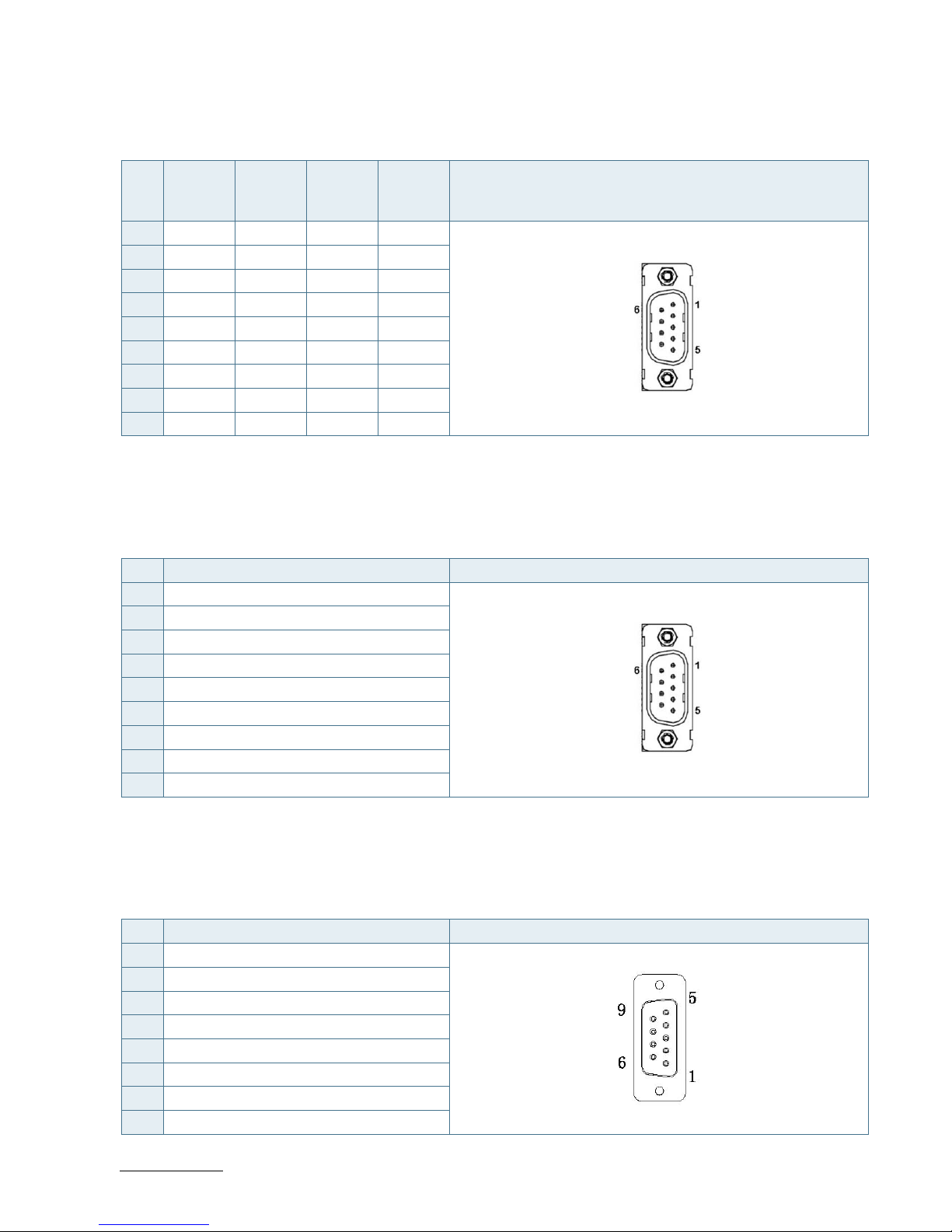
RuggedClient-HSW - User Guide, Rev. 1.0
www.kontron.com
// 43
10.1.7. RS232/422/485 Serial Port
Table 12: RS232/422/485 Serial Port (see Figure 2, pos. 10)
Pin RS232 RS422 RS485
Half
Duplex
RS485
Full
Duplex
COM1, COM2 (9-pin D-SUB Male Connector)
1 DCD TX- DATA- TX-
2 RXD TX+ DATA+ TX+
3 TXD RX+ N/A RX+
4 DTR RX- N/A RX-
5 GND GND GND GND
6 DSR N/A N/A N/A
7 RTS N/A N/A N/A
8 CTS N/A N/A N/A
9 RI N/A N/A N/A
10.1.8. RS232 Serial Port
Table 13: RS232 Serial Port (see Figure 2, pos. 11)
Pin Signal Name COM3, COM4 (9-pin D-SUB Male Connector)
1 DCD
2 RXD
3 TXD
4 DTR
5 GND
6 DSR
7 RTS
8 CTS
9 RI
10.1.9. DIO Port
Table 14: DIO Port (see Figure 2, pos. 12)
Pin Signal Name DIO (9-pin D-SUB Female Connector)
1 Digital Output 0
2 Digital Input 0
3 Digital Output 1
4 Digital Input 1
5 Digital Output 2
6 Digital Input 2
7 Digital Output 3
8 Digital Input 3
Page 44

RuggedClient-HSW - User Guide, Rev. 1.0
www.kontron.com
// 44
Pin Signal Name DIO (9-pin D-SUB Female Connector)
9 +5V
10.1.10. Line-Out Connector
Table 15: Line-Out Connector (see Figure 2, pos. 6)
Pin Signal Name Line-Out Connector & Corresponding Audio Jack
Tip Line-Out_L
Ring Line-Out_R
Sleeve GND
10.1.11. Mic-In Connector
Table 16: Mic-In Connector (see Figure 2, pos. 7)
Pin Signal Name Mic-In Connector & Corresponding Audio Jack
Tip Mic-In_L
Ring Mic-In_R
Sleeve GND
Page 45

RuggedClient-HSW - User Guide, Rev. 1.0
www.kontron.com
// 45
11/ uEFI BIOS
11.1. Starting the uEFI BIOS
The RuggedClient-HSW is provided with a Kontron-customized, pre-installed and configured version of AMI Aptio® V
uEFI BIOS. AMI BIOS firmware is based on the Unified Extensible Firmware Interface (uEFI) specification and the Intel®
Platform Innovation Framework for EFI. This uEFI BIOS provides a variety of new and enhanced functions specifically
tailored to the hardware features of the RuggedClient-HSW.
The BIOS version covered in this document might not be the latest version. The latest
version might have certain differences to the BIOS options and features described in
this chapter.
The uEFI BIOS comes with a setup program that provides quick and easy access to the individual function settings for
control or modification of the uEFI BIOS configuration. The setup program allows the accessing of various menus that
provide functions or access to sub-menus with more specific functions of their own.
To start the uEFI BIOS setup program, follow the steps below:
1. Power on the board.
2. Wait until the first characters appear on the screen (POST messages or splash screen).
3. Press the <DEL> key.
4. If the uEFI BIOS is password-protected, a request for password will appear. Enter either the User Password or the
Supervisor Password (see Security menu), press <RETURN>, and proceed with step 5.
5. A setup menu will appear.
The RuggedClient-HSW uEFI BIOS setup program uses a hot key-based navigation system. A hot key legend bar is
located on the bottom of the setup screens.
The following table provides information concerning the usage of these hot keys.
Table 17: Navigation Hot Keys Available in the Legend Bar
Hotkeys Description
<F1> The <F1> key invokes the General Help window.
<-> The <Minus> key selects the next lower value within a field.
<+> The <Plus> key selects the next higher value within a field.
<F2> The <F2> key loads the previous values.
<F3> The <F3> key loads the standard default values.
<F4> The <F4> key saves the current settings and exit the uEFI BIOS setup.
<→> or <←>
The <Left/Right> arrows selects major setup menus on the menu bar. For example:
Main, Advanced, Security, etc.
<↑> or <↓>
The <Up/Down> arrows selects fields in the current menu. For example: A setup
function or a sub-screen.
<ESC> The <ESC> key exits a major setup menu and enter the Exit setup menu.
Pressing the <ESC> key in a sub-menu displays the next higher menu level.
<RERURN> The <RETURN> key executes a command or select a submenu.
Page 46

RuggedClient-HSW - User Guide, Rev. 1.0
www.kontron.com
// 46
11.2. Setup Menus
The Setup utility features shows six menus in the selection bar at the top of the screen:
Main
Advanced
Power
Boot
Security
Save & Exit
The Setup menus are selected via the left and right arrow keys. The currently active menu and the currently active
uEFI BIOS Setup item are highlighted in white. Each Setup menu provides two main frames. The left frame displays all
available functions. Functions that can be configured are displayed in blue. Functions displayed in gray provide
information about the status or the operational configuration. The right frame displays an Item Specific Help window
providing an explanation of the respective function.
11.2.1. Main Setup Menu
Upon entering the uEFI BIOS Setup program, the Main Setup menu is displayed. This screen lists the Main Setup menu
sub-screens and provides basic system information. Additionally functions for setting the system time and date are
offered.
Table 18: Main Setup Menu Sub-Screens and Functions
Function Description
BIOS Information Read only field.
Displays information about the system BIOS
Memory Information Read only field.
Displays information about total memory
ME Information Read only field.
Displays information about Intel Management Engine (ME) version
Firmware Information Code version and firmware information
System Date Set System Date
System Time Set System Time
Page 47

RuggedClient-HSW - User Guide, Rev. 1.0
www.kontron.com
// 47
Figure 14: BIOS Main Menu Screen System Data and Time
BIOS SETUP UTILITY
Main Advanced Power Boot Security Save & Exit
Product Information
Product Name RuggedClient-HSWQ-150-R
BIOS Version R 1.00 (x64)
BIOS Build Date 07/30/2015
ME FW Version 9.0.30.1482
CPU Information
Intel® Celeron® CPU 2950M @ 2.00GHz
Microcode Revision 17
Processor Cores 2
→ ←: Select Screen
Memory Information
↑ ↓: Select Item
Total Size 2048 MB (DDR3) Enter: Select
Frequency 1333 MHz +/-: Change Opt.
F1: General Help
System Date [Mon 01/06/2014] F2: Previous Values
System Time [01:35:24] F3: Optimized Defaults
F4: Save & Exit
Access Level Administrator ESC: Exit
Version 2.15.1236. Copyright (C) 2012, American Megatrends, Inc.
Feature Option Description
System Date [dd/mm/yyyy] Set the Date. Use Tab to switch between Data elements.
System Time [hh:mm:ss] Set the Time. Use Tab to switch between Time elements.
Page 48

RuggedClient-HSW - User Guide, Rev. 1.0
www.kontron.com
// 48
11.2.2. Advanced Setup Menu
The Advanced setup menu provides sub-screens and functions for advanced configurations. The following subscreen functions are included in the menu:
LAN & Audio Configuration
Display Configuration
Super IO Configuration
CPU Chipset Configuration
SATA Configuration
USB Configuration
Intel® Rapid Start Technology
DIO Configuration
H/W Monitor
Setting items on this screen to incorrect values may cause the system to malfunction.
Page 49

RuggedClient-HSW - User Guide, Rev. 1.0
www.kontron.com
// 49
Figure 15: BIOS Advanced Menu
BIOS SETUP UTILITY
Main Advanced Power Boot Security Save & Exit
Onboard LAN1 Controller [Enabled]
Onboard LAN1 Boot [Disabled]
Onboard LAN2 Controller [Enabled]
Onboard LAN2 Boot [Disabled]
Audio Controller [Enabled]
→ ←: Select Screen
> Display Configuration
↑ ↓: Select Item
> Super IO Configuration Enter: Select
> CPU Chipset Configuration +/-: Change Opt.
> SATA Configuration F1: General Help
> USB Configuration F2: Previous Values
> Intel® Rapid Start Technology F3: Optimized Defaults
> DIO Configuration F4: Save & Exit
> H/W Monitor ESC: Exit
Version 2.15.1236. Copyright (C) 2012, American Megatrends, Inc.
Feature Option Description
Onboard LAN1
Controller
[Disabled], [Enabled] Select whether to enable or disable Onboard LAN1 Controller.
Onboard LAN1 Boot [Disabled], [Enabled] Select whether to enable or disable load onboard PXE (Preboot
Execution Environment).
Onboard LAN2
Controller
[Disabled], [Enabled] Select whether to enable or disable Onboard LAN2 Controller.
Onboard LAN2 Boot [Disabled], [Enabled] Select whether to enable or disable load onboard PXE (Preboot
Execution Environment).
Audio Controller [Disabled], [Enabled] Select whether to enable or disable Audio Controller.
Page 50
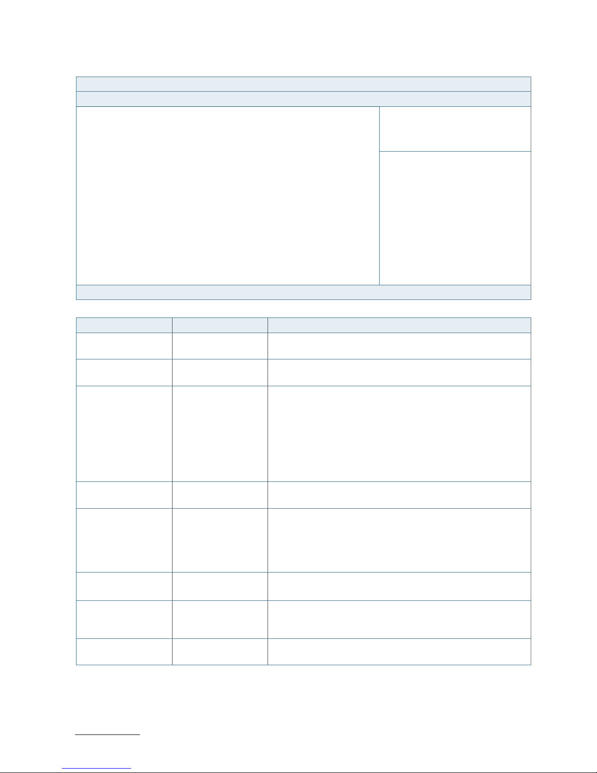
RuggedClient-HSW - User Guide, Rev. 1.0
www.kontron.com
// 50
Figure 16: BIOS Advanced Menu - Display Configuration
BIOS SETUP UTILITY
Main Advanced Power Boot Security Save & Exit
Display Configuration
Primary Display [Auto]
UWA Frame Buffer Size [256MB]
→ ←: Select Screen
DVMT Pre-Allocated [64MB]
↑ ↓: Select Item
DVMT Total Gfx Mem [256MB] Enter: Select
+/-: Change Opt.
Primary IGFX Boot Display [VBIOS Default] F1: General Help
Active LVDS [Enabled] F2: Previous Values
LVDS Panel Type [1024x768 24Bit 1CH] F3: Optimized Defaults
LVDS Backlight Control - Voltage [3.0V] F4: Save & Exit
LVDS Backlight Control - PWM 127 ESC: Exit
Version 2.15.1236. Copyright (C) 2012, American Megatrends, Inc.
Feature Option Description
Primary Display [Auto], [IGFX], [PCIE] Select which graphic controller to be used as the primary
display device.
UWA Frame Buffer
Size
[128MB], [256MB],
[512MB]
Select the Aperture Size.
DVMT Pre-Allocated [32M], [64M], [96M],
[128M], [160M],
[192M], [224M],
[256M], [288M],
[320M], [352M],
[384M], [416M],
[448M], [480M],
[512M], [1024M]
Select DVMT Pre-Allocated (Fixed) Graphics Memory size used
by the Internal Graphics Device.
DVMT Total Gfx Mem [128M], [256M], [MAX] Select DVMT Total Graphic Memory size used by the Internal
Graphics Device.
Primary IGFX Boot
Display
[VBIOS Default],
[CRT], [HDMI], [DVI],
[LVDS]
Select the Video Device which will be activated during POST. This
has no effect if external graphics present.
Secondary boot display selection will appear based on your
selection.
DOS modes will be supported only on primary display.
Active LVDS [Disabled], [Enabled] Select the Active LVDS Configuration.
[Enabled]: VBIOS will enable LVDS.
LVDS Panel Type [1024x 768 24Bit
1CH], [1280x1024
24Bit 2CH]
[1024x 768 24Bit 1CH] for 15" model
[1280x1024 24Bit 2CH] for 17" model
LVDS Backlight
Control - Voltage
[3.0V] Select the voltage of LVDS backlight control mode.
Page 51

RuggedClient-HSW - User Guide, Rev. 1.0
www.kontron.com
// 51
Figure 17: BIOS Advanced Menu - Super IO Configuration
BIOS SETUP UTILITY
Main Advanced Power Boot Security Save & Exit
Super IO Configuration
> Serial Port 1 Configuration
→ ←: Select Screen
> Serial Port 2 Configuration
↑ ↓: Select Item
> Serial Port 3 Configuration Enter: Select
> Serial Port 4 Configuration +/-: Change Opt.
F1: General Help
F2: Previous Values
F3: Optimized Defaults
F4: Save & Exit
ESC: Exit
Version 2.15.1236. Copyright (C) 2012, American Megatrends, Inc.
Figure 18: BIOS Advanced Menu - Super IO Configuration - Serial Port 1 Configuration
BIOS SETUP UTILITY
Main Advanced Power Boot Security Save & Exit
Serial Port 1 Configuration
Serial Port [Enabled]
→ ←: Select Screen
Device Settings IO=3F8h; IRQ=4;
↑ ↓: Select Item
Enter: Select
Change Setting [Auto] +/-: Change Opt.
Serial Port 1 Type [RS232] F1: General Help
F2: Previous Values
F3: Optimized Defaults
F4: Save & Exit
ESC: Exit
Version 2.15.1236. Copyright (C) 2012, American Megatrends, Inc.
Feature Option Description
Serial Port [Disabled], [Enabled] Select whether to enable or disable Serial Port (COM).
Change Settings [Auto], [IO=3F8h;
IRQ=4;], [IO=3F8h;
IRQ=3, 4, 5, 6, 7, 10, 11,
12;], [IO=2F8h; IRQ=3,
4, 5, 6, 7, 10, 11, 12;],
[IO=3E8h; IRQ=3, 4, 5,
6, 7, 10, 11, 12;],
[IO=2E8h; IRQ=3, 4, 5,
6, 7, 10, 11, 12;]
Select an optional setting for Super IO device.
Serial Port 1 Type [RS232], [RS422],
[RS485]
Select an appropriate type for Serial Port 1.
Page 52
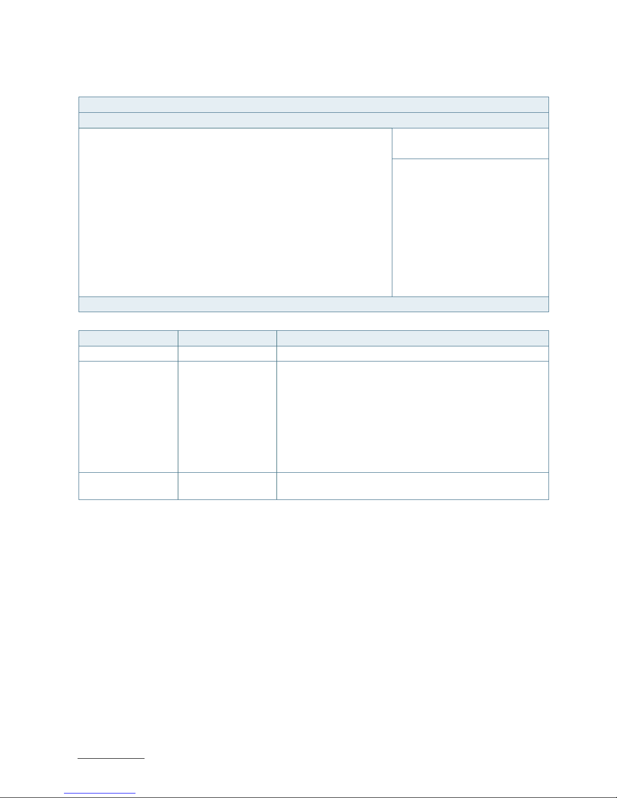
RuggedClient-HSW - User Guide, Rev. 1.0
www.kontron.com
// 52
Figure 19: BIOS Advanced Menu - Super IO Configuration - Serial Port 2 Configuration
BIOS SETUP UTILITY
Main Advanced Power Boot Security Save & Exit
Serial Port 2 Configuration
Serial Port [Enabled]
→ ←: Select Screen
Device Settings IO=2F8h; IRQ=3;
↑ ↓: Select Item
Enter: Select
Change Setting [Auto] +/-: Change Opt.
Serial Port 2 Type [RS232] F1: General Help
F2: Previous Values
F3: Optimized Defaults
F4: Save & Exit
ESC: Exit
Version 2.15.1236. Copyright (C) 2012, American Megatrends, Inc.
Feature Option Description
Serial Port [Disabled], [Enabled] Select whether to enable or disable Serial Port (COM).
Change Settings [Auto], [IO=2F8h;
IRQ=3;], [IO=3F8h;
IRQ=3, 4, 5, 6, 7, 10, 11,
12;], [IO=2F8h; IRQ=3,
4, 5, 6, 7, 10, 11, 12;],
[IO=3E8h; IRQ=3, 4, 5,
6, 7, 10, 11, 12;],
[IO=2E8h; IRQ=3, 4, 5,
6, 7, 10, 11, 12;]
Select an optional setting for Super IO device.
Serial Port 2 Type [RS232], [RS422],
[RS485]
Select an appropriate type for Serial Port 2.
Page 53

RuggedClient-HSW - User Guide, Rev. 1.0
www.kontron.com
// 53
Figure 20: BIOS Advanced Menu - Super IO Configuration - Serial Port 3 Configuration
BIOS SETUP UTILITY
Main Advanced Power Boot Security Save & Exit
Serial Port 3 Configuration
Serial Port [Enabled]
→ ←: Select Screen
Device Settings IO=260h; IRQ=11;
↑ ↓: Select Item
Enter: Select
Change Setting [Auto] +/-: Change Opt.
F1: General Help
F2: Previous Values
F3: Optimized Defaults
F4: Save & Exit
ESC: Exit
Version 2.15.1236. Copyright (C) 2012, American Megatrends, Inc.
Feature Option Description
Serial Port [Disabled], [Enabled] Select whether to enable or disable Serial Port (COM).
Change Settings [Auto], [IO=260h;
IRQ=11;], [IO=260h;
IRQ=10, 11, 12;],
[IO=268h; IRQ=10, 11,
12;], [IO=270h; IRQ=10,
11, 12;], [IO=278h;
IRQ=10, 11, 12;]
Select an optional setting for Super IO device.
Page 54

RuggedClient-HSW - User Guide, Rev. 1.0
www.kontron.com
// 54
Figure 21: BIOS Advanced Menu - Super IO Configuration - Serial Port 4 Configuration
BIOS SETUP UTILITY
Main Advanced Power Boot Security Save & Exit
Serial Port 4 Configuration
Serial Port [Enabled]
→ ←: Select Screen
Device Settings IO=268h; IRQ=11;
↑ ↓: Select Item
Enter: Select
Change Setting [Auto] +/-: Change Opt.
F1: General Help
F2: Previous Values
F3: Optimized Defaults
F4: Save & Exit
ESC: Exit
Version 2.15.1236. Copyright (C) 2012, American Megatrends, Inc.
Feature Option Description
Serial Port [Disabled], [Enabled] Select whether to enable or disable Serial Port (COM).
Change Settings [Auto], [IO=268h;
IRQ=11;], [IO=260h;
IRQ=10, 11, 12;],
[IO=268h; IRQ=10, 11,
12;], [IO=270h; IRQ=10,
11, 12;], [IO=278h;
IRQ=10, 11, 12;]
Select an optional setting for Super IO device.
Page 55
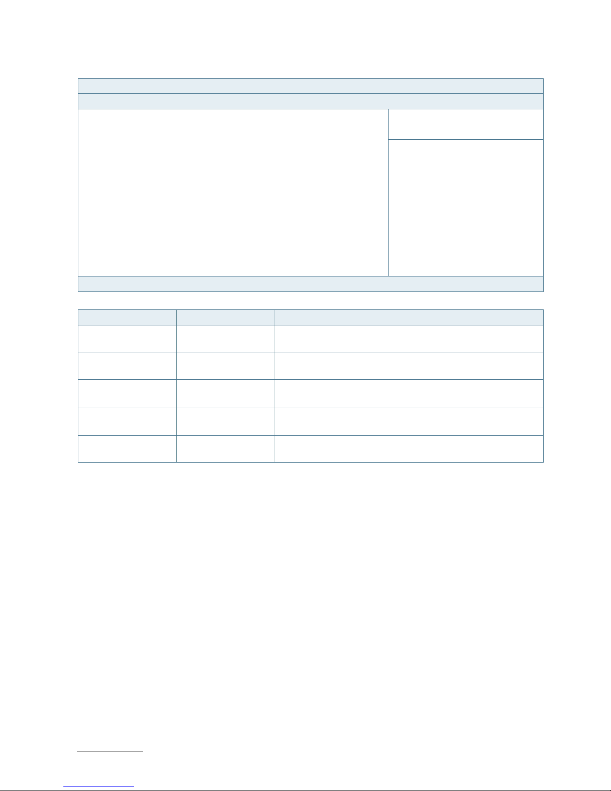
RuggedClient-HSW - User Guide, Rev. 1.0
www.kontron.com
// 55
Figure 22: BIOS Advanced Menu - CPU Advanced Configuration
BIOS SETUP UTILITY
Main Advanced Power Boot Security Save & Exit
CPU Advanced Configuration
EIST [Enabled]
→ ←: Select Screen
Active Processor Cores [All]
↑ ↓: Select Item
Limit CPUID Maximum [Disabled] Enter: Select
Execute Disable Bit [Enabled] +/-: Change Opt.
Intel Virtualization Technology [Disabled] F1: General Help
F2: Previous Values
F3: Optimized Defaults
F4: Save & Exit
ESC: Exit
Version 2.15.1236. Copyright (C) 2012, American Megatrends, Inc.
Feature Option Description
EIST [Disabled], [Enabled] Select whether to enable or disable Enhanced Intel SpeedStep
Technology.
Active Processor
Cores
[All], [1] Select the number of cores to enable in each processor package.
Limit CPUID Maximum [Disabled], [Enabled] Select whether to limit CPUID maximum value.
Execute Disable Bit [Disabled], [Enabled] Select whether to enable or disable Execute Disable Bit
functionality, which prevents malicious buffer overflow attacks..
Intel Virtualization
Technology
[Disabled], [Enabled] Select whether to enable or disable Intel Virtualization
Technology.
Page 56
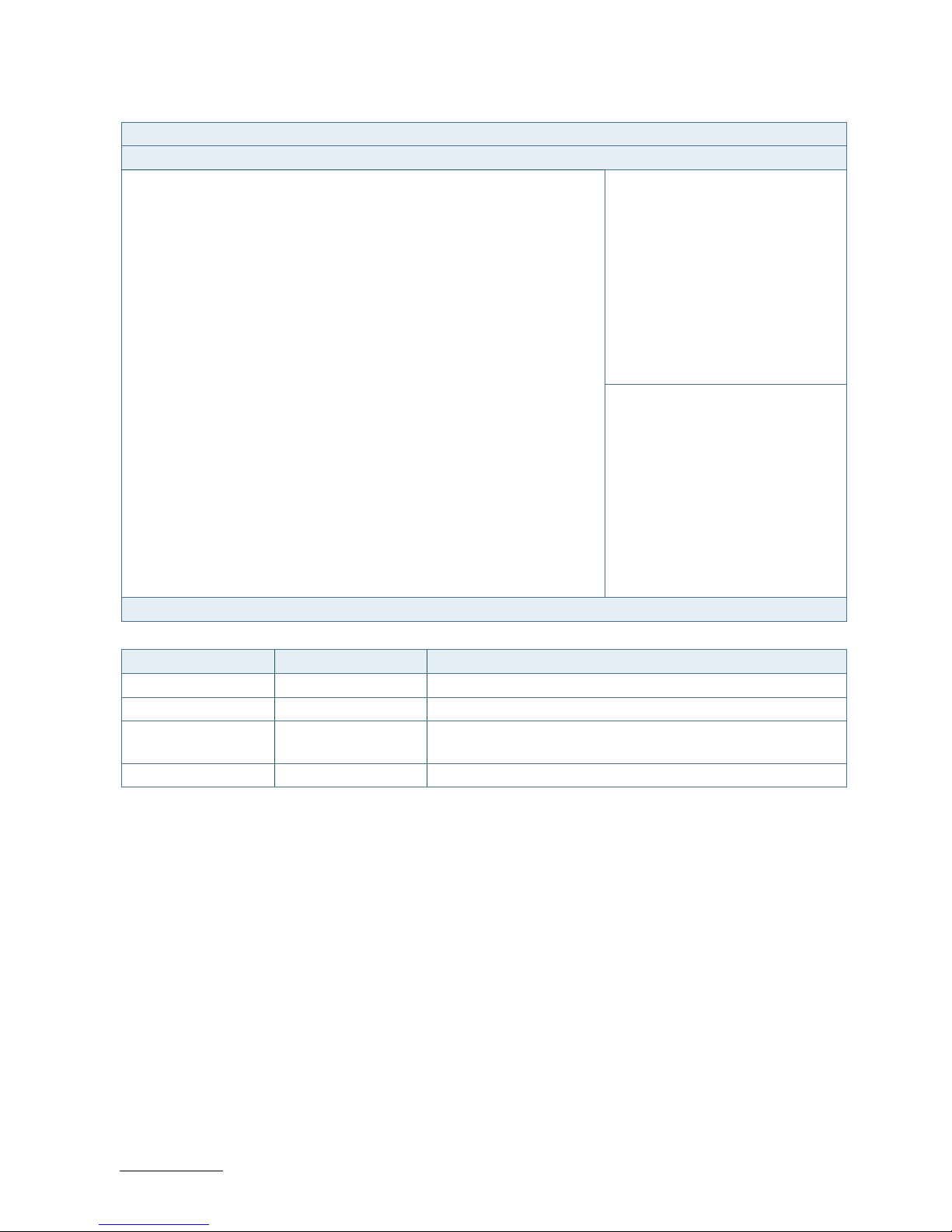
RuggedClient-HSW - User Guide, Rev. 1.0
www.kontron.com
// 56
Figure 23: BIOS Advanced Menu - SATA Configuration
BIOS SETUP UTILITY
Main Advanced Power Boot Security Save & Exit
SATA Configuration
SATA Controller(s) [Enabled]
SATA Mode Selection [AHCI]
SATA Controller Speed [Default]
Serial ATA Port 1 WDC WD1600BEVT (160.0GB)
Port 1 [Enabled]
Serial ATA Port 2 Empty
Port 2 [Enabled]
→ ←: Select Screen
Serial ATA Port 3 Empty
↑ ↓: Select Item
Port 3 [Enabled] Enter: Select
Serial ATA Port 4 Empty +/-: Change Opt.
Port 5 [Enabled] F1: General Help
Serial ATA Port 5 Empty F2: Previous Values
Port 5 [Enabled] F3: Optimized Defaults
Serial ATA Port 6 Empty F4: Save & Exit
Port 6 [Enabled] ESC: Exit
Version 2.15.1236. Copyright (C) 2012, American Megatrends, Inc.
Feature Option Description
SATA Controller(s) [Enabled], [Disabled] Select whether to enable or disable SATA Device.
SATA Mode Selection [IDE], [AHCI], [RAID] Determine how SATA controller(s) operate.
SATA Controller
Speed
[Default], [Gen1],
[Gen2], [Gen3]
Indicate the maximum speed the SATA controller can support.
Port 1..6 [Disabled], [Enabled] Select whether to enable or disable SATA Port 1..6.
Page 57

RuggedClient-HSW - User Guide, Rev. 1.0
www.kontron.com
// 57
Figure 24: BIOS Advanced Menu - USB Configuration
BIOS SETUP UTILITY
Main Advanced Power Boot Security Save & Exit
USB Configuration
USB Devices:
→ ←: Select Screen
1 Keyboard, 1 Mouse, 1 Point, 2 Hubs
↑ ↓: Select Item
Enter: Select
Legacy USB Support [Enabled] +/-: Change Opt.
USB3.0 Support [Enabled] F1: General Help
XHCI Hand-off [Enabled] F2: Previous Values
EHCI Hand-off [Disabled] F3: Optimized Defaults
USB Mass Storage Driver Support [Enabled] F4: Save & Exit
ESC: Exit
Version 2.15.1236. Copyright (C) 2012, American Megatrends, Inc.
Feature Option Description
Legacy USB Support [Enabled], [Disabled],
[Auto]
Select whether to enable or disable Legacy USB support.
AUTO option disables legacy support if no USB devices are
connected.
USB3.0 Support [Enabled], [Disabled] Select whether to enable or disable USB 3.0 support.
XHCI Hand-off [Enabled], [Disabled] Select whether to enable or disable XHCI Hand-off function.
This is a workaround for OSes without XHCI hand-off support.
The XHCI ownership change should be claimed by XHCI driver.
EHCI Hand-off [Disabled], [Enabled] Select whether to enable or disable EHCI Hand-off function.
USB Mass Storage
Driver Support
[Disabled], [Enabled] Select whether to enable or disable USB Mass Storage Driver
Support.
Page 58
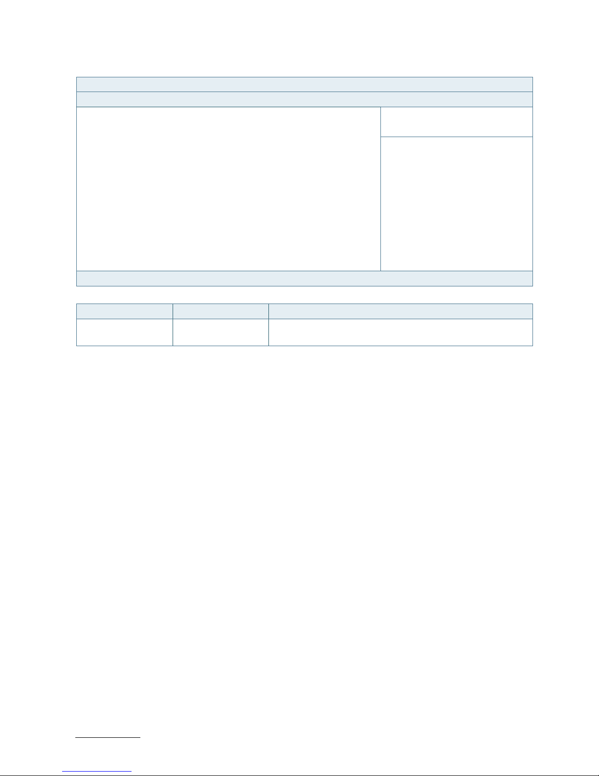
RuggedClient-HSW - User Guide, Rev. 1.0
www.kontron.com
// 58
Figure 25: BIOS Advanced Menu - Intel® Rapid Start Technology
BIOS SETUP UTILITY
Main Advanced Power Boot Security Save & Exit
Intel® Rapid Start Technology [Disabled]
→ ←: Select Screen
↑ ↓: Select Item
Enter: Select
+/-: Change Opt.
F1: General Help
F2: Previous Values
F3: Optimized Defaults
F4: Save & Exit
ESC: Exit
Version 2.15.1236. Copyright (C) 2012, American Megatrends, Inc.
Feature Option Description
Intel® Rapid Start
Technology
[Enabled], [Disabled] Select whether to enable or disable Intel® Rapid Start
Technology.
Page 59
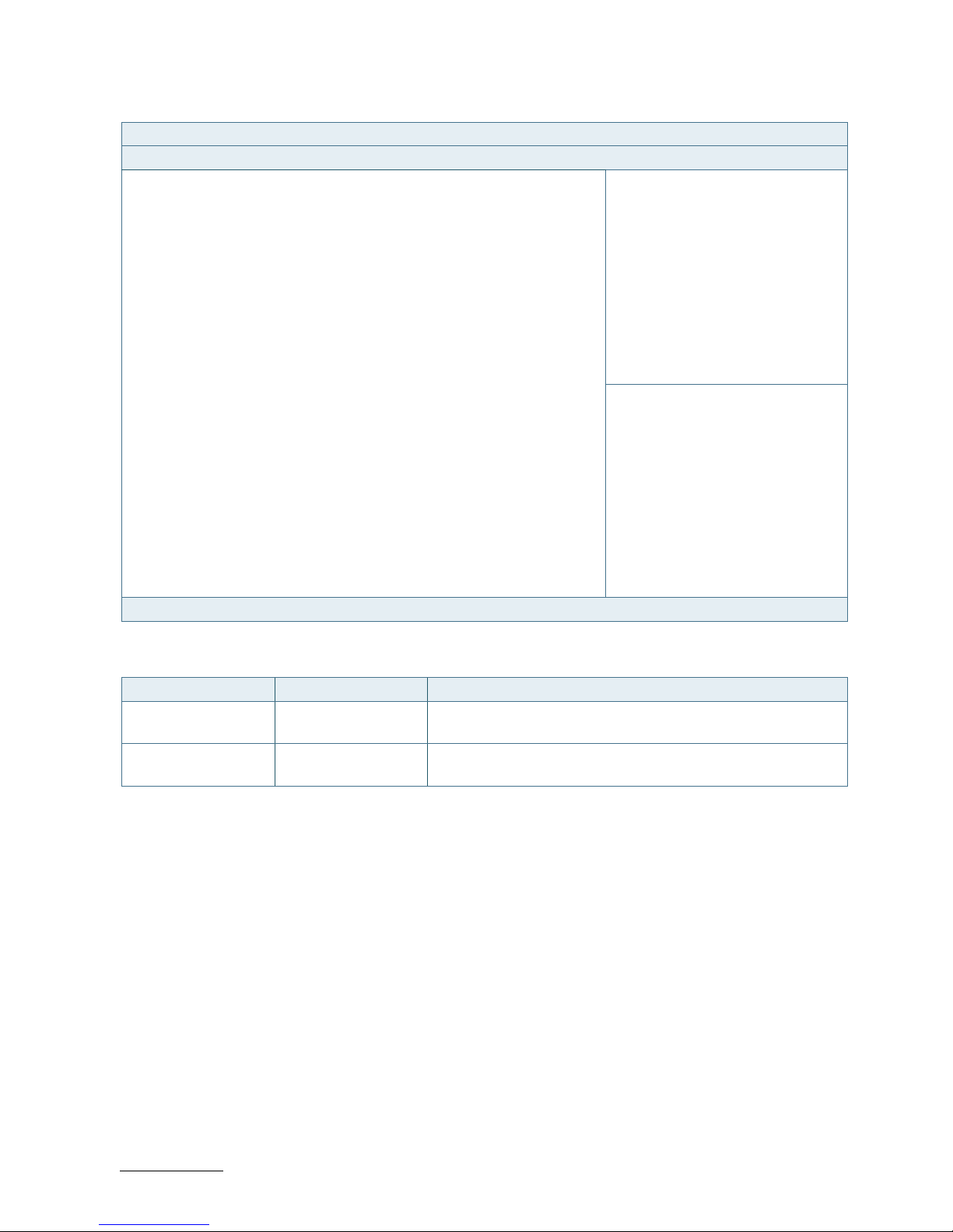
RuggedClient-HSW - User Guide, Rev. 1.0
www.kontron.com
// 59
Figure 26: BIOS Advanced Menu - DIO Configuration
BIOS SETUP UTILITY
Main Advanced Power Boot Security Save & Exit
Intel® Rapid Start Technology [Disabled]
User Configuration [Enabled]
DO_1* [Output Low]
DO_2* [Output Low]
DO_3* [Output Low]
DO_4* [Output Low]
DI_1 1
→ ←: Select Screen
DI_2 1
↑ ↓: Select Item
DI_3 1 Enter: Select
DI_4 1 +/-: Change Opt.
F1: General Help
DO_1 1 F2: Previous Values
DO_2 1 F3: Optimized Defaults
DO_3 1 F4: Save & Exit
DO_4 1 ESC: Exit
Version 2.15.1236. Copyright (C) 2012, American Megatrends, Inc.
* These items appear only when enbling User Configuration.
Feature Option Description
User Configuration [Enabled], [Disabled] Select whether or not to allow user to set the DIO pin output
value.
DO_1..4 [Output Low], [Output
High]
Set up the DIO pin output value.
Page 60

RuggedClient-HSW - User Guide, Rev. 1.0
www.kontron.com
// 60
Figure 27: BIOS Advanced Menu - H/W Monitor
BIOS SETUP UTILITY
Main Advanced Power Boot Security Save & Exit
PC Health Status
CPU Temperature : +41 C
Memory Temperature : +37 C
System Temperature : +37 C
→ ←: Select Screen
↑ ↓: Select Item
CPU Fan Speed : 2590 RPM Enter: Select
SYS Fan Speed : 6024 RPM +/-: Change Opt.
F1: General Help
+VCORE : +1.744 V F2: Previous Values
+VIN : +11.616 V F3: Optimized Defaults
+5V : +5.017 V F4: Save & Exit
+3.3V : +3.308 V ESC: Exit
Version 2.15.1236. Copyright (C) 2012, American Megatrends, Inc.
Page 61

RuggedClient-HSW - User Guide, Rev. 1.0
www.kontron.com
// 61
11.2.3. Power Setup Menu
The Power setup menu provides functions and a sub-screen for power configurations. The following sub-screen
function is included in the menu:
WatchDog Timer Configuration
Figure 28: BIOS Power Setup Menu
BIOS SETUP UTILITY
Main Advanced Power Boot Security Save & Exit
Power Configuration
ACPI Sleep State [S3 only (Suspend to RAM)]
Restore AC Power Loss [Power Off]
→ ←: Select Screen
Power Saving Mode [Disabled]
↑ ↓: Select Item
Enter: Select
Resume Event Control +/-: Change Opt.
Resume By PCIE Device [Disabled] F1: General Help
Resume By Ring Device [Disabled] F2: Previous Values
F3: Optimized Defaults
> WatchDog Timer Configuration F4: Save & Exit
ESC: Exit
Version 2.15.1236. Copyright (C) 2012, American Megatrends, Inc.
Feature Option Description
ACPI Sleep State [Suspend Disabled],
[S3 only (Suspend to
RAM)]
Select whether to enable or disable suspend function and
determine an appropriate suspend mode.
Restore AC Power
Loss
[Power Off], [Power
On], [Last State]
Control whether the system will stay on after AC power is
removed and then restored.
Select [Power Off] if you want the system to remain off after
power restored.
Select [Power On] if you use a power strip to turn the system on.
Power Saving Mode [Disabled], [EUP
Enabled], [DeepSx
Enabled]
Select whether to enable Power Saving Mode.
Resume By PCIE
Device
[Disabled], [Enabled] Select whether to enable or disable Wake from PCIE Device.
Resume By Ring
Device
[Disabled], [Enabled] Select whether to enable or disable Wake from Ring Device.
Page 62
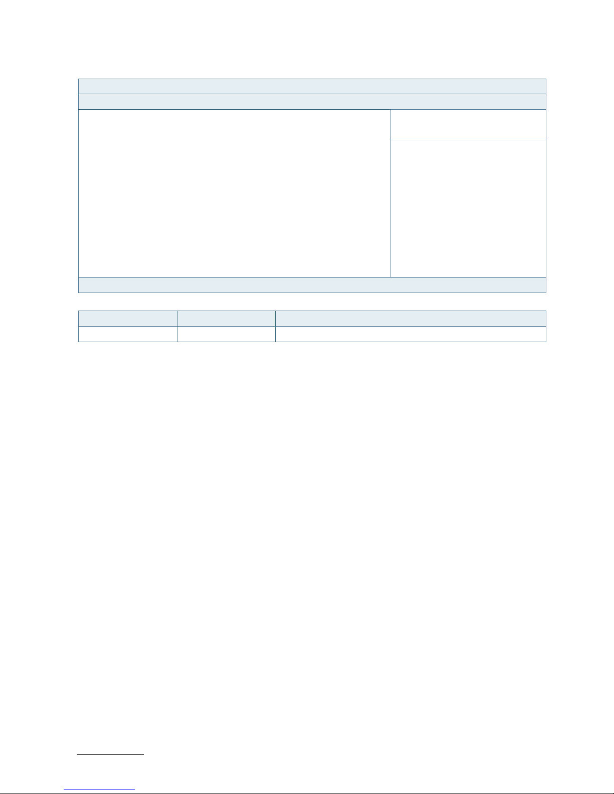
RuggedClient-HSW - User Guide, Rev. 1.0
www.kontron.com
// 62
Figure 29: BIOS Power Setup Menu - WatchDog Timer Configuration
BIOS SETUP UTILITY
Main Advanced Power Boot Security Save & Exit
WatchDog Timer Configuration
WDT Function [Disabled]
→ ←: Select Screen
↑ ↓: Select Item
Enter: Select
+/-: Change Opt.
F1: General Help
F2: Previous Values
F3: Optimized Defaults
F4: Save & Exit
ESC: Exit
Version 2.15.1236. Copyright (C) 2012, American Megatrends, Inc.
Feature Option Description
WDT Function [Disabled], [Enabled] Select whether to enable or disable WatchDog Timer function.
Page 63
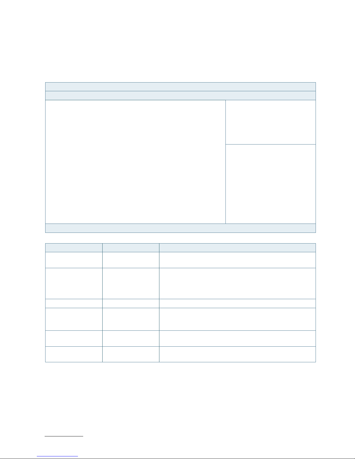
RuggedClient-HSW - User Guide, Rev. 1.0
www.kontron.com
// 63
11.2.4. Boot Setup Menu
The boot setup menu lists the for boot device priority order, that is generated dynamically.
Figure 30: BIOS Boot Setup Menu
BIOS SETUP UTILITY
Main Advanced Power Boot Security Save & Exit
Boot Configuration
Full Screen LOGO Display [Disabled]
Setup Prompt Timeout 1
Bootup NumLock State [On]
CSM Support [Enabled]
→ ←: Select Screen
Boot Option Filter [Legacy only]
↑ ↓: Select Item
DIMM Voltage [Enabled] Enter: Select
Keyboard Detect Warning [Enabled] +/-: Change Opt.
F1: General Help
Boot Option Filter F2: Previous Values
Boot Option #1 F3: Optimized Defaults
F4: Save & Exit
Hard Drive BBS Priorities ESC: Exit
Version 2.15.1236. Copyright (C) 2012, American Megatrends, Inc.
Feature Option Description
Full Screen LOGO
Display
[Disabled], [Enabled] Select whether to enable or disable to display logo screen.
Bootup NumLock
State
[On], [Off] Select the state of the NumLock feature of the keyboard after
Startup.
[On]: The keys on the keypad will act as numeric keys.
[Off]: The keys on the keypad will act as cursor keys.
CSM Support [Enabled], [Disabled] Select whether to enable or disable CSM support.
Boot Option Filter [UEFI and Legacy],
[Legacy only], [UEFI
only]
Control Legacy / UEFI ROMs priority.
DIMM Voltage
Warning
[Disabled], [Enabled] Select whether to enable or disable DIMM Voltage Warning.
Keyboard Detect
Warning
[Enabled], [Disabled] Select whether to enable or disable Keyboard Detect Warning
function.
Page 64
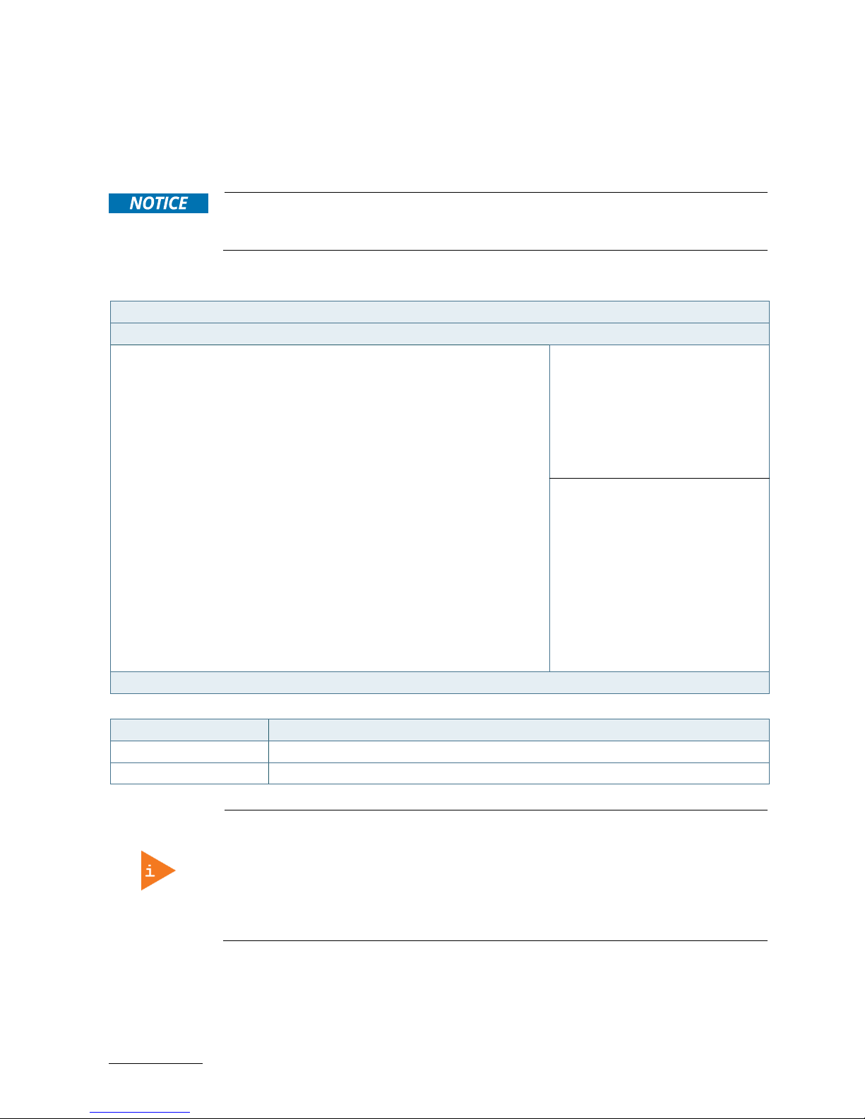
RuggedClient-HSW - User Guide, Rev. 1.0
www.kontron.com
// 64
11.2.5. Security Setup Menu
The Security setup menu provides information about the passwords and functions for specifying the security settings.
The passwords are case-sensitive. The RuggedClient-HSW provides no factory-set passwords.
If there is already a password installed, the system asks for this first. To clear a
password, simply enter nothing and acknowledge by pressing <RETURN>. To set a
password, enter it twice and acknowledge by pressing <RETURN>.
Figure 31: BIOS Security Setup Menu
BIOS SETUP UTILITY
Main Advanced Power Boot Security Save & Exit
Password Description
If ONLY the Administrator’s password is set, then this only limits access to
Setup and is only asked for when entering Setup
If ONLY the User’s password is set, then this is a power on password and
must be entered to boot or enter Setup. In Setup the User will have
Administrator rights
The password length must be in the following range:
→ ←: Select Screen
Minimum Length 3
↑ ↓: Select Item
Maximum length 20 Enter: Select
+/-: Change Opt.
Administrator Password F1: General Help
User Password F2: Previous Values
F3: Optimized Defaults
F4: Save & Exit
ESC: Exit
Version 2.15.1236. Copyright (C) 2012, American Megatrends, Inc.
Feature Description
Administrator Password Set administrator password
User Password Set user password
If only the administrator’s password is set, then only access to setup is limited. The
password is only entered when entering setup.
If only the user’s password is set, then the password is a power on password and must
be entered to boot or enter setup. Within the setup menu the user has administrator
rights.
Password length requirements are maximum 20 characters and minimum 3 characters.
Page 65

RuggedClient-HSW - User Guide, Rev. 1.0
www.kontron.com
// 65
11.2.5.1. Remember the password
It is highly recommended to keep a record of all passwords in a safe place. Forgotten passwords results in being
locked out of the system.
If the system cannot be booted because the User Password or the Supervisor Password are not know, contact
Kontron Support for further assistance.
HDD security passwords cannot be cleared using the above method.
Page 66
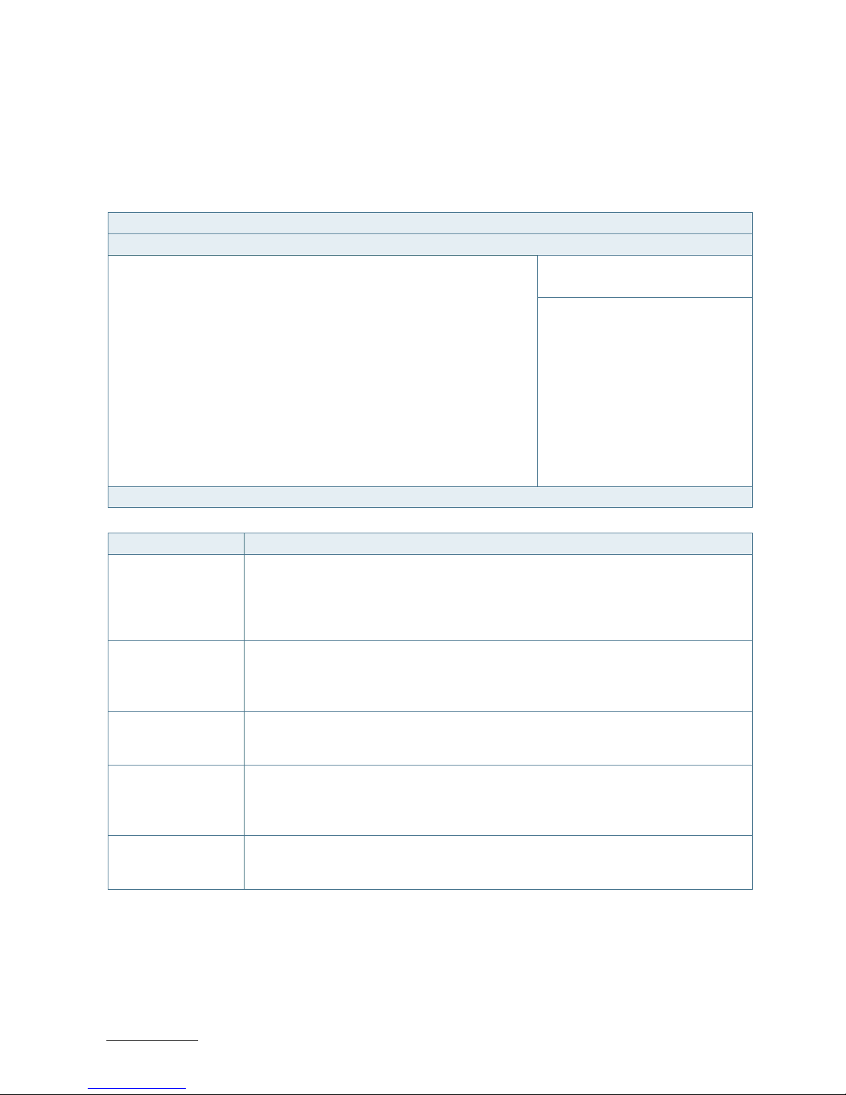
RuggedClient-HSW - User Guide, Rev. 1.0
www.kontron.com
// 66
11.2.6. Save & Exit Setup Menu
The exit setup menu provides functions for handling changes made to the UEFI BIOS settings and the exiting of the
setup program.
Figure 32: BIOS Save & Exit Setup Menu
BIOS SETUP UTILITY
Main Advanced Power boot Security Save & Exit
Save Changes and Reset
Discard Changes and Reset
→ ←: Select Screen
Save Options
↑ ↓: Select Item
Save Changes Enter: Select
Discard Changes +/-: Change Opt.
F1: General Help
Restore Defaults F2: Previous Values
F3: Optimized Defaults
F4: Save & Exit
ESC: Exit
Version 2.15.1236. Copyright (C) 2012, American Megatrends, Inc.
Feature Description
Save Changes and
Exit
Exit system setup after saving the changes. Once you are finished making your
selections, choose this option from the Exit menu to ensure the values you selected are
saved to the CMOS RAM. The CMOS RAM is sustained by an onboard backup battery and
stays on even when the PC is turned off. When you select this option, a confirmation
window appears. Select [Yes] to save changes and exit.
Discard Changes and
Exit
Exit system setup without saving any changes. Select this option only if you do not want
to save the changes that you made to the Setup program. If you made changes to fields
other than system date, system time, and password, the BIOS asks for a confirmation
before exiting.
Save Changes Save changes done so far to any of the setup values. This option allows you to save the
selections you made. After selecting this option, a confirmation appears. Select [Yes] to
save any changes.
Discard Changes Discards changes done so far to any of the setup values. This option allows you to
discard the selections you made and restore the previously saved values. After selecting
this option, a confirmation appears. Select [Yes] to discard any changes and load the
previously saved values.
Restore Defaults Restore Default values for all the setup values. This option allows you to load optimal
default values for each of the parameters on the Setup menus, which will provide the
best performance settings for your system. The F9 key can be used for this operation.
Page 67

RuggedClient-HSW - User Guide, Rev. 1.0
www.kontron.com
// 67
Appendix A: List of Acronyms
The following table does not contain the complete acronyms used in signal names,
signal type definitions or similar. A description of the signals is included in the I/O
Connector and Internal connector chapters within this user guide.
Table 19: List of Acronyms
2D Two-Dimensional
3D Three-Dimensional
AT Advanced Technology
ATX Advanced Technology eXtended
BGA Ball Grid Array
BIOS Basic Input / Output System
BSP Board Support Package
CMOS Complementary Metal Oxide
Semiconductor
CPU Central Processing Unit
DC Direct Current
DDC Display Data Channel
DIO Digital Input / Output
ECC Error-Correcting Code
EEE Electrical and Electronic Equipment
EOS Electrical OverStress
ESD ElectroStatic Discharge
GbE Gigabit Ethernet
HDD Hard Disk Drive
HDMI High Definition Multimedia Interface
LAN Local Area Network
LED Light Emitting Device
LVDS Low-Voltage Differential Signaling
ME F/W Management Engine Firmware
mPCIe mini Peripheral Component Interconnect
express
PC-AT Personal Computer - Advanced
Technology
PCB Printed Circuit Board
PSU Power Supply Unit
PVC PolyViny Chloride
PWM Pulse Width Modulation
RAM Random Access Memory
ROM Read-Only Memory
RTC Real-Time Clock
SATA Serial Advanced Technology Attachment
SDP Serial Download Protocol
SELV Safety Extra-Low Voltage
SIM Subscriber Identity Module
SMBus System Management Bus
SoC System on Chip
SO-DIMM Small Outline Dual In-line Memory
Module
SPD Serial Presence Detect
SPI Serial Peripheral Interface
TDP Thermal Design Power
TPM Trusted Platform Module
UEFI Unified Extensible Firmware Interface
USB Universal Serial Bus
UTP Update Transfer Protocol
VGA Video Graphics Array
WDT WatchDog Timer
WEEE Waste Electrical and Electronic
Equipment
Page 68

RuggedClient-HSW – User Guide, Rev. 1.0
www.kontron.com
// 68
About Kontron
Kontron is a global leader in embedded computing technology (ECT). As a part of technology group S&T,
Kontron offers a combined portfolio of secure hardware, middleware and services for Internet of
Things (IoT) and Industry 4.0 applications. With its standard products and tailor-made solutions based
on highly reliable state-of-the-art embedded technologies, Kontron provides secure and innovative
applications for a variety of industries. As a result, customers benefit from accelerated time-to-market,
reduced total cost of ownership, product longevity and the best fully integrated applications overall.
Kontron is a listed company. Its shares are traded in the Prime Standard segment of the Frankfurt Stock
Exchange and on other exchanges under the symbol "KBC". For more information, please visit:
www.kontron.com
CORPORATE OFFICES
EUROPE, MIDDLE EAST
& AFRICA
NORTH AMERICA
ASIA PACIFIC
Lise-Meitner-Str. 3-5
86156 Augsburg
Germany
Tel.: + 49 821 4086-0
Fax: + 49 821 4086-111
info@kontron.com
9477 Waples Street
San Diego, CA 92121
USA
Tel.: + 1 888 294 4558
Fax: + 1 858 677 0898
info@us.kontron.com
1~2F, 10 Building, No. 8 Liangshuihe 2nd Street,
Economical & Technological Development Zone,
Beijing, 100176, P.R. China
Tel.: + 86 10 63751188
Fax: + 86 10 83682438
info@kontron.cn
 Loading...