

Page 1
pITX-SP
KTD-S0003-C
Page 2

User Information
Table of Contents
» Table of Contents «
1 User Information .............................................................................1
1.1 About This Document.................................................................................................... 1
1.2 Copyright Notice.......................................................................................................... 1
1.3 Trademarks................................................................................................................. 1
1.4 Standards................................................................................................................... 1
1.5 Warranty .................................................................................................................... 1
1.6 Life Support Policy ....................................................................................................... 2
1.7 Technical Support ........................................................................................................ 2
2 BIOS Update ...................................................................................3
2.1 AFUDOS (AMI) ............................................................................................................. 3
2.2 AFUWIN (AMI) ............................................................................................................. 3
2.3 BFLASH (KONTRON) ...................................................................................................... 3
3 Graphics Interface............................................................................4
3.1 LCD/LVDS Technology Overview ...................................................................................... 4
3.1.1 Detailed Timing Descriptor (EDID or DisplayIDTM) ............................................................................. 4
3.1.2 24 Bit Color Mapping Tips............................................................................................................6
3.2 EDID 1.3 Specification (VESA) ........................................................................................ 7
3.3 DisplayIDTM Specification (VESA) ..................................................................................... 7
3.3.1 DisplayIDTM Parameter Summary ...................................................................................................7
3.3.2 DisplayIDTM Restrictions ..............................................................................................................8
3.3.3 LCD Panel Selection ................................................................................................................... 8
3.3.4 DisplayID
3.3.5 Building DisplayIDTM File ........................................................................................................... 10
3.3.6 Erasing DisplayIDTM Record ........................................................................................................ 10
3.3.7 EEPROM Update Tool ................................................................................................................ 10
3.4 What means GMA and IEGD? ..........................................................................................11
3.4.1 The GMA Driver........................................................................................................................ 11
3.4.1.1 DVI Monitor Selection............................................................................................................... 12
3.4.2 The IEGD Driver ....................................................................................................................... 12
TM
Windows
®
Tool .......................................................................................................... 9
3.5 H.264 Support for Linux ...............................................................................................13
4 Serial-ATA Interface ....................................................................... 14
4.1 Native PCI IDE Controller ..............................................................................................14
4.2 RAID/AHCI Controller ..................................................................................................14
pITX-SP Software Guide
Page 3

User Information
Table of Contents
5 SDIO/microSD Card Interface............................................................ 15
5.1 DOS Boot...................................................................................................................15
5.2 Linux Boot.................................................................................................................15
5.3 Windows
5.4 Windows
®
XP and Windows
®
XP Embedded or Windows
®
7 Boot.................................................................................16
®
7 Embedded Boot......................................................16
6 CPLD Interface............................................................................... 17
6.1 Special Hints..............................................................................................................18
6.1.1 Reserved Bits.......................................................................................................................... 18
6.1.2 GPIO Input Register ................................................................................................................. 18
6.1.3 Fan Divisor ............................................................................................................................. 18
6.2 Programming Examples................................................................................................19
6.2.1 Watchdog Example................................................................................................................... 19
6.2.2 Digital I/O Example.................................................................................................................. 20
6.2.3 I2C with GPIOs Example ............................................................................................................ 21
6.2.4 GPIO IRQ Example.................................................................................................................... 27
6.2.5 Fan Control Example ................................................................................................................ 30
6.2.6 Fan Speed Example .................................................................................................................. 31
7 Tri-Axis Accelerometer Example ........................................................ 33
8 DOS Problems................................................................................ 36
8.1 Keyboard Driver..........................................................................................................36
8.2 DR-DOS 7.03 ..............................................................................................................36
8.3 Gate A20 and LAN Boot ................................................................................................36
9 ACPI Thermal Management............................................................... 37
9.1 Passive Cooling ..........................................................................................................37
9.2 Active Cooling ............................................................................................................37
9.3 Temperature Limits .....................................................................................................37
9.4 Temperature Identifier.................................................................................................37
10 ACPI Wakeup ................................................................................. 38
10.1 Wake On USB..............................................................................................................38
10.1.1 Windows® XP .......................................................................................................................... 38
10.1.2 Linux .................................................................................................................................... 38
pITX-SP Software Guide
Page 4

User Information
Table of Contents
11 JIDA32 Interface............................................................................ 39
11.1 Generic Part...............................................................................................................39
11.2 Display Part ...............................................................................................................39
11.3 I2C-Bus Part ..............................................................................................................39
11.3.1 Bus Number 0 (JIDA)................................................................................................................ 40
11.3.2 Bus Number 1 (Generic) ............................................................................................................ 40
11.3.3 BusNumber 2 (JILI) ................................................................................................................. 40
11.4 CPU Performance Part ..................................................................................................40
11.5 Hardware Monitor Part.................................................................................................41
11.5.1 Temperature........................................................................................................................... 41
11.6 Digital I/O Part...........................................................................................................41
11.7 Watchdog Part............................................................................................................41
11.8 JIDA32 Windows® Programming.....................................................................................42
11.8.1 Program Language C ................................................................................................................ 42
11.8.2 Program Language DELPHI ........................................................................................................ 43
11.8.3 Program Language VISUAL BASIC (VB.NET)................................................................................... 46
11.8.4 Module Definition File .............................................................................................................. 48
11.9 JIDA32 Linux Programming...........................................................................................50
12 Linux Support ............................................................................... 52
12.1 openSUSE® 11.1 .........................................................................................................52
12.2 Fedora® 11 ................................................................................................................52
12.3 Reboot Problem..........................................................................................................53
Appendix A: Reference Documents .............................................................. 54
Appendix B: Document Revision History .......................................................55
pITX-SP Software Guide
Page 5

KTD-S0003-C Page 1 User Information
1 User Information
1.1 About This Document
This document provides information about products from KONTRON Technology A/S and/or its subsidiaries.
No warranty of suitability, purpose or fitness is implied. While every attempt has been made to ensure that
the information in this document is accurate the information contained within is supplied “as-is” - no
liability is taken for any inaccuracies. Manual is subject to change without prior notice.
KONTRON assumes no responsibility for the circuits, descriptions and tables indicated as far as patents or
other rights of third parties are concerned.
1.2 Copyright Notice
Copyright © 2009-2010, KONTRON Technology A/S, ALL RIGHTS RESERVED.
No part of this document may be reproduced or transmitted in any form or by any means, electronically or
mechanically, for any purpose without the express written permission of KONTRON Technology A/S.
1.3 Trademarks
Brand and product names are trademarks or registered trademarks of their respective owners.
1.4 Standards
KONTRON Technology A/S is certified to ISO 9000 standards.
1.5 Warranty
This product is warranted against defects in material and workmanship for the warranty period from the
date of shipment. During the warranty period KONTRON Technology A/S will at its discretion decide to
repair or replace defective products.
Within the warranty period the repair of products is free of charge as long as warranty conditions are
observed.
The warranty does not apply to defects resulting from improper or inadequate maintenance or handling by
the buyer, unauthorized modification or misuse, operation outside of the product’s environmental specifications or improper installation or maintenance.
KONTRON Technology A/S will not be responsible for any defects or damages to third party products that
are caused by a faulty KONTRON Technology A/S product.
pITX-SP Software Guide
Page 6

KTD-S0003-C Page 2 User Information
1.6 Life Support Policy
KONTRON Technology's products are not for use as critical components in life support devices or systems
without express written approval of the general manager of KONTRON Technology A/S.
As used herein:
Life support devices or systems are devices or systems which
a) are intended for surgical implant into body or
b) support or sustain life and whose failure to perform, when properly used in accordance with instructions
for use provided in the labelling, can be reasonably expected to result in significant injury to the user.
A critical component is any component of a life support device or system whose failure to perform can be
reasonably expected to cause the failure of the life support device or system or to affect its safety or
effectiveness.
1.7 Technical Support
Please consult our web site at http://www.kontron.com/support for the latest product documentation,
utilities, drivers and support contacts
. In any case you can always contact your board supplier for technical
support.
Before contacting support please be prepared to provide as much information as possible:
Board identification:
Board configuration:
System environment:
Type
Part number (find PN on label)
Serial number (find SN on label)
DRAM type and size
BIOS revision (find in the BIOS Setup)
BIOS settings different than default settings (refer to the BIOS Setup section)
O/S type and version
Driver origin and version
Attached hardware (drives, USB devices, LCD panels ...)
pITX-SP Software Guide
Page 7
KTD-S0003-C Page 3 BIOS Update
2 BIOS Update
The AMI and the KONTRON update tool is available for two operating systems: DOS and Windows® (e.g.
®
Windows
Software conditions:
2.1 AFUDOS (AMI)
Only the following combination of command line arguments has been tested and should be used for the
update process. The syntax of the DOS update tool is:
AFUDOS <BIOS filename> /X /P /B /N /C
/X = don't check ROM ID
/P = program main BIOS
/B = program boot block
/N = overwrite NVRAM (setup settings)
/C = destroy CMOS checksum
XP, Vista 32/64 or Windows® 7).
Operating System Tool Name Required Revision
DOS
Windows®
AFUWIN.EXE + UCORESYS.SYS (UCOREW64.SYS) 4.41 or greater
AFUDOS.EXE 4.23 or greater
BF.EXE 7.41 or greater
BF.EXE 7.41 or greater
2.2 AFUWIN (AMI)
For 32bit operating systems the file UCORESYS.SYS and for 64bit systems the file UCOREW64.SYS must be
used (located in the same folder as AFUWIN.EXE). AFUWIN can either be executed using the same command
line parameters as for AFUDOS or it can be executed in GUI mode by double klicking on it.
2.3 BFLASH (KONTRON)
In this manual the abbreviation BF is used for BFlash. This also matches with the actual name of the tool
(BF.EXE). BF can be used to read and write data to and from BIOS flash. With this tool it's possible to
update the BIOS, change DMI codes, setup vendor codes and save copies of all data. The copies can be used
as master data for mass production.
Type BF <ret> from DOS prompt to see the BFlash version number and the board version. Only the following
combination of command line arguments has been tested and should be used for the update process.
BF read <BIOS filename> 0 100000
BF write <BIOS filename> 0
pITX-SP Software Guide
Page 8

KTD-S0003-C Page 4 Graphics Interface
3 Graphics Interface
3.1 LCD/LVDS Technology Overview
3.1.1 Detailed Timing Descriptor (EDID or DisplayIDTM)
The input fields Pixel Clock, Horizontal Active, Horizontal Blank, Horizontal Sync Offset, Horizontal Sync
Width, Vertical Active, Vertical Blank, Vertical Sync Offset and Vertical Sync Width must be filled in with the
correct values according to the panel’s data sheet. In many cases the value for Horizontal/Vertical Blank
cannot be read directly from the data sheet. Instead terms such as Display Period (active pixels/lines) or
Horizontal/Vertical Total appear.
In this case the following calculation can be made:
⇒ Blank Value = Total Value – Active Value.
Sometimes the datasheet does not specify Sync Offset and/or Sync Width. In this case the permissible
values can only be determined though testing. However the rule is:
⇒ The sum of Sync Offset and Sync Width must not exceed the value for Horizontal/Vertical Blank.
Also datasheets are often different for displays with double pixel clock. If Pixel Clock and Horizontal Values
seem to be halved this must be corrected for input:
⇒ The values must always be entered as though it were a panel with single pixel clock.
Example 1:
PRIMEVIEW PM070WL4 (single pixel clock)
Data sheet specifications:
Clock Frequency [typ.] 32 MHz
HSync Period [typ.] 1056 Clocks (equivalent to Horizontal Total)
HSync Display Period [typ.] 800 Clocks (equivalent to Horizontal Active)
HSync Pulse Width [typ.] 128 Clocks
HSync Front Porch [typ.] 42 Clocks
HSync Back Porch [typ.] 86 Clocks
VSync Period [typ.] 525 Lines (equivalent to Vertical Total)
VSync Display Period 480 Lines (equivalent to Vertical Active)
VSync Pulse Width [typ.] 2 Lines
VSync Front Porch [typ.] 10 Lines
VSync Back Porch [typ.] 33 Lines
Result:
Pixel Clock 32
Horizontal Active 800
Horizontal Blank 256 ((128 + 42 + 86) → H. Pulse Width + H. Front Porch + H.
Back Porch)
Horizontal Sync Offset 42 (H. Front Porch)
Horizontal Sync Width 128 (H. Pulse Width)
Vertical Active 480
Vertical Blank 45 ((2 + 10 + 33) → V. Pulse Width + V. Front Porch + V. Back
Porch)
Vertical Sync Offset 10 (V. Front Porch)
Vertical Sync Width 3 (V. Pulse Width)
pITX-SP Software Guide
Page 9
KTD-S0003-C Page 5 Graphics Interface
Example 2 (not useable on pITX-SP):
SHARP LQ190E1LW01 (double pixel clock)
Data sheet specifications (no definition of Sync Offset and Sync Width):
Clock Frequency [typ.] 54 MHz
Horizontal Period (1) [typ.] 844 Clocks (equivalent to Horizontal Total)
Horizontal Display Period 640 Clocks (equivalent to Horizontal Active)
Vertical Period [typ.] 1066 Lines (equivalent to Vertical Total)
Vertical Display Period 1024 Lines (equivalent to Vertical Active)
Result:
Pixel Clock 108 (2 x 54 MHz)
Horizontal Active 1280 (2 x 640 Clocks)
Horizontal Blank 408 ((844 – 640) x 2 Clocks)
Horizontal Sync Offset 45 (normally approx. 10 – 15 % of Horizontal Blank)
Horizontal Sync Width 140 (normally approx. 30 – 70 % of Horizontal Blank)
Vertical Active 1024
Vertical Blank 42 (1066 – 1024 Lines)
Vertical Sync Offset 1 (normally approx. 1 – 3 Lines)
Vertical Sync Width 3 (normally approx. 1 – 15 Lines)
Example 3 (not useable on pITX-SP):
LG-PHILIPS LM170E01-TLA1 (double pixel clock)
Data sheet specifications:
Clock Frequency [typ.] 54 MHz
Hsync Period [typ.] 844 Clocks
Horiz. Valid [typ.] 640 Clocks
Horiz. Back Porch [typ.] 124 Clocks
Horiz. Front Porch [typ.] 24 Clocks
Vsync Period [typ.] 1066 Lines
Vert. Valid [typ.] 1024 Lines
Vert. Back Porch [typ.] 38 Lines
Vert. Front Porch [typ.] 1 Line
Result:
Pixel Clock 108 (2 x 54 MHz)
Horizontal Active 1280 (2 x 640 Clocks → Horizontal Addr. Time)
Horizontal Blank 408 ((844 – 640) x 2 Clocks)
Horizontal Sync Offset 48 (2 x 24 Clocks → Horizontal Front Porch)
Horizontal Sync Width 112 (((408/2 – 124 – 24) x 2) → H. Blank – H. Back Porch – H.
Front Porch)
Vertical Active 1024 (Vertical Addr. Time)
Vertical Blank 42 (1066 – 1024 Lines)
Vertical Sync Offset 1 (Vertical Front Porch)
Vertical Sync Width 3 (Vertical Blank – Vertical Back Porch – Vertical Front Porch)
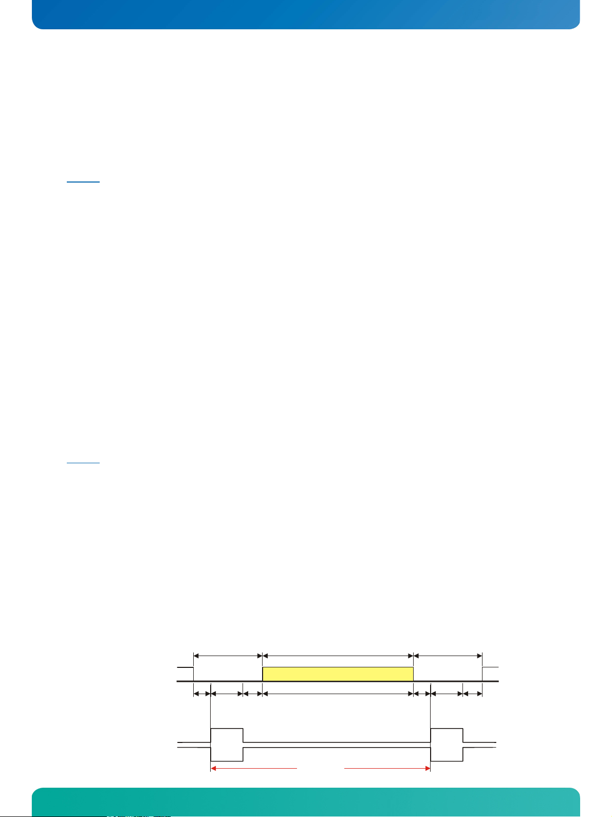
The following picture shows the typical video timing.
Timing Parameter Definitions
Blanking
Active Part
Blanking
H-/V-Video
Front
Porch
H-/V-Sync
Sync
Pulse
Width
pos.
Sync
neg.
Sync
Back
Porch
Address Time
Total
pITX-SP Software Guide
Front
Porch
Sync
Pulse
Width
pos.
Sync
neg.
Sync
Back
Porch
Page 10

KTD-S0003-C Page 6 Graphics Interface
ce
3.1.2 24 Bit Color Mapping Tips 3.1.2 24 Bit Color Mapping Tips
The double pixel clock or 24-bit color depth can generally be taken from the datasheet. There are two
The double pixel clock or 24-bit color depth can generally be taken from the datasheet. There are two
interface modes existing at 24-bit color depth: FPDI (F
interface modes existing at 24-bit color depth: FPDI (F
I
nterface). Some panels use the line SELL LVDS (SELect Lvds data order). The LVDS data assignment in the
lat Panel Display Interface) or LDI (LVDS Display
datasheet can give you an indication by the last channel (e.g. RX3/TX3 – SELL LVDS = low) wether it is a LDI
panel (contains the lowest bits). Most panels have a FPDI interface.
Example:
FPDI data assignment (LVDS channel 3 even or odd):
Tx/Rx27 Red 6 (e.g. even: RE6 or ER6)
Tx/Rx5 Red 7
Tx/Rx10 Green 6 (e.g. even: GE6 or EG6)
Tx/Rx11 Green 7
Tx/Rx16 Blue 6 (e.g. even: BE6 or EB6)
Tx/Rx17 Blue 7
Tx/Rx23 not used
LDI data assignment (LVDS channel 3 even or odd):
Tx/Rx27 Red 0 (e.g. even: RE0 or ER0)
Tx/Rx5 Red 1
Tx/Rx10 Green 0 (e.g. even: GE0 or EG0)
Tx/Rx11 Green 1
Tx/Rx16 Blue 0 (e.g. even: BE0 or EB0)
Tx/Rx17 Blue 1
Tx/Rx23 not used
TxClk
TxOut0
G0
R5
R4
R3
R2 R1
R0
FPDI
TxOut1
TxOut2
B1
DE
B0
VS
G5 G4 G3 G2 G1
HS
B5
B4
B3
B2
TxOut3
B7
B6
G7 G6 R7
R6
t
cycle
LDI
TxClk
TxOut0
TxOut1
G2 R7 R6 R5
B3
R4
R3
R2
G3G4G5G6G7B2
TxOut2
TxOut3
DE VS HS B7 B6 B5
B1
B0 G1 G0
R1
B4
R0
pITX-SP Software Guide
pITX-SP Software Guide
Page 11
KTD-S0003-C Page 7 Graphics Interface
3.2 EDID 1.3 Specification (VESA)
The EDID (Extended Display Identification Data) record has a fixed structure. The first 8 bytes contain the
distinctive identification 00h, FFh, FFh, FFh, FFh, FFh, FFh, 00h. The end of the record is marked by the
checksum (1 byte). The result of the addition of all bytes including the checksum has to be zero.
For a comprehensive support of the majority of available panels you don't need all fields of the EDID
record. The Detailed Timing Descriptor (18 bytes) is the most important field. No 24bit panels (FPDI/LDI)
are supported though. This means EDID should only be used for 18bit panels.
For further information please consult the official EDID specification from the VESA comitee which has to be
payed.
3.3 DisplayID
TM
Specification (VESA)
Intended as a replacement for all previous EDID versions DisplayIDTM contains many new features. It's a
structure with several well defined elements (tags). Not every element that is listed in the specification has
to be part of the resulting data set (basic section).
KONTRON has decided to use this selection of tags (mandatory presence).
Tag Description
00h Product Identification Data Block (Vendor ID, Product Code, Manufacturing Date ...)
03h Type I Detailed Timing Data Block (Pixel Clock, Horizontal/Vertical Data ...)
0Ch Display Device Data Block (Device Technology, Operating Mode, Color Depth ...)
0Dh Interface Power Sequencing Data Block (Power On/Off Timing)
0Fh Display Interface Data Block (Interface Type, Interface Attribute ...)
3.3.1 DisplayIDTM Parameter Summary
Only a part of the parameters used in the DisplayIDTM Windows® tool are interpreted by a specific board. The
following table shows a summary of the used parameters (valid for pITX-SP).
Group Parameter Comment
Type I Timing Pixel Clock
Type I Timing Horizontal Active
Type I Timing Horizontal Blank
Type I Timing Horizontal Sync Offset Front porch
Type I Timing Horizontal Sync Width
Type I Timing Vertical Active
Type I Timing Vertical Blank
Type I Timing Vertical Sync Offset Front porch
Type I Timing Vertical Sync Width
Display Interface 1 Bits per Pixel Color depth (18 or 24bit)
Display Interface 2 Signal Polarity Only H-Sync and V-Sync
pITX-SP Software Guide
Page 12
KTD-S0003-C Page 8 Graphics Interface
3.3.2 DisplayIDTM Restrictions
Depending on the graphic controller not all features can be used. The following table shows the most important restrictions.
Restrictions for pITX-SP
Panels with dual or quad clock not supported (2 or 4 Pixel per Clock)
Panels with LDI 24bit color mapping not supported
Only normal DE mode possible
Variable power sequencing not supported
3.3.3 LCD Panel Selection
The choice of an LCD display is basically defined by two parameters.
Parameter Value
Pixel per Clock (Channels) 1
Maximum Pixel Clock 112 MHz
Currently this leads to a maximum resolution of
With the GMA driver (see details below) it is not guaranteed that every resolution can be achieved. There
can also be differences between the Windows
the correct function of the board for untypical resolution. In principal the use of DisplayID
lizing every special display resolution. For this a valid DisplayID
EEPROM. Additionally the BIOS Setup entry
must be set to Auto.
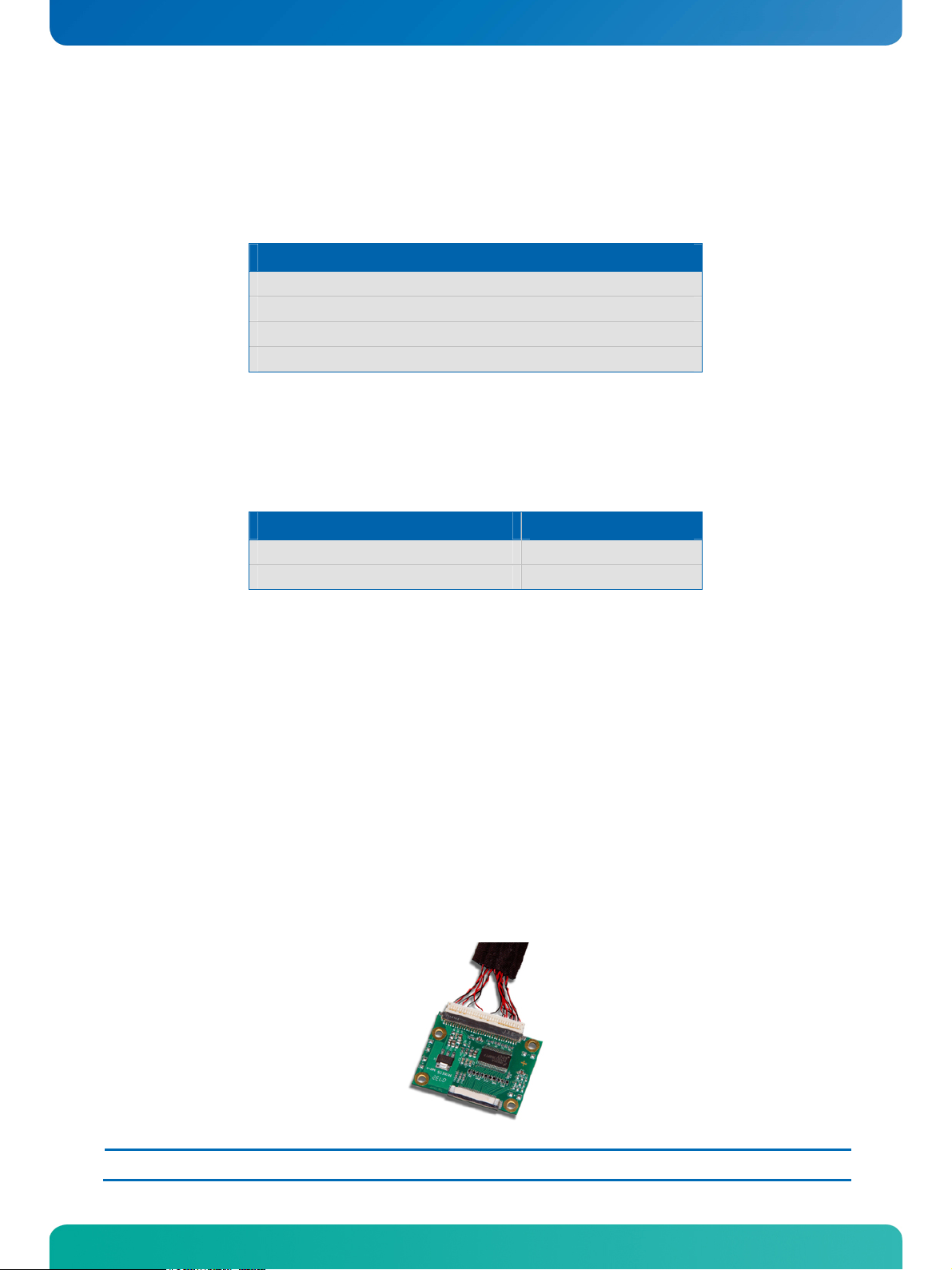
Many displays with a resolution up to XGA (1024 x 768) have a digital (TTL) interface. KONTRON offers a
special adapter to connect these displays to the LVDS interface (KAB-ADAPT-LVDStoTTL with part number
61029).
1366 x 768 Pixel (e.g. SHARP LK315T3LA31)
®
XP und Windows® Vista driver. KONTRON does not guarantee
TM
dataset must be written to the onboard
Advanced/Display Configuration/Flat Panel Type
TM
allows rea-
Note: The fact that a display is mentioned as an example does not mean that this display is approved by KONTRON.
pITX-SP Software Guide
Page 13
KTD-S0003-C Page 9 Graphics Interface
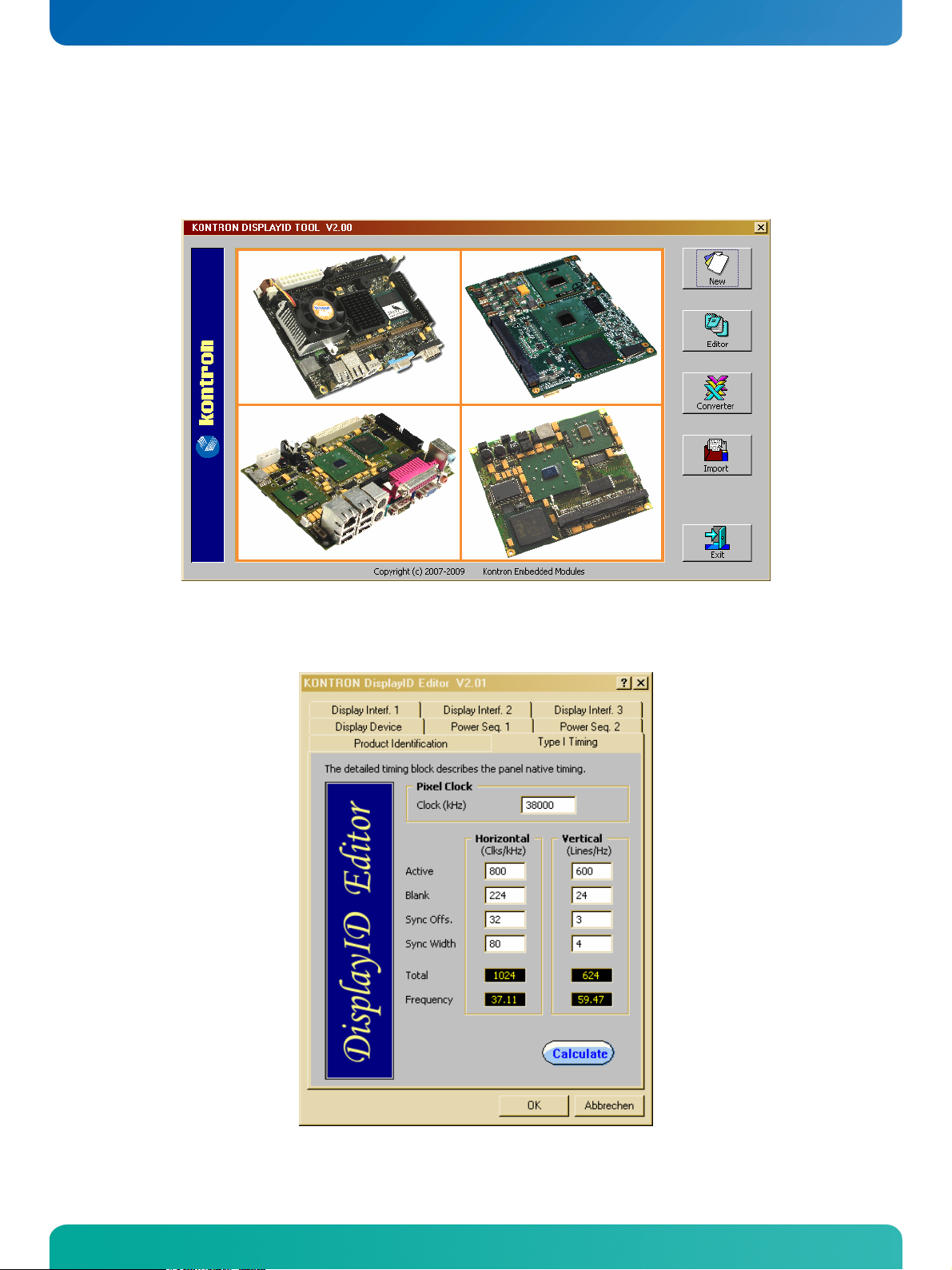
3.3.4 DisplayIDTM Windows® Tool
The DisplayIDTM parameter can be modified with the DisplayIDTM Windows® tool.
For an example the following picture shows the input fields for the Detailed Timing parameters.
For more information see the documentation of the DisplayID
kontron.com).
pITX-SP Software Guide
TM
tool (software can be downloaded from
Page 14

KTD-S0003-C Page 10 Graphics Interface
The DisplayIDTM Editor saves the parameters in a intermediate file format. The file extension is 'KDD' (Kon-
isplayIDTM Data). This file format cannot be used to program the onboard EEPROM.
tron D
For transfering this file format into the binary file format for the EEPROM apply the Converter.
3.3.5 Building DisplayIDTM File
Start the Windows® tool DisplayID.exe.
Use the Editor if you want to modify an existing DisplayIDTM file or select New to create a
complete new record.
Change respectively enter new parameters.
Save the parameters in a file with the extension 'KDD'.
Open the saved 'KDD'-file using the Converter.
Save the binary file with the extension 'KDB' (Kontron DisplayIDTM Binary).
Program the onboard EEPROM using the board specific DOS update tool.
3.3.6 Erasing DisplayIDTM Record
Programming the first 128 bytes in the EEPROM with the values 00h or FFh deletes a valid DisplayIDTM
record.
3.3.7 EEPROM Update Tool
The syntax of the DOS EEPROM update tool is:
PXSP-DID <option> <filename>
/W = read a file (must be KDB-format) and write the content to the EEPROM
/R = read the EEPROM and write the content to a file
/C = read a file and compare the content with the EEPROM
/D = clear the EEPROM content (without filename)
pITX-SP Software Guide
Page 15
KTD-S0003-C Page 11 Graphics Interface
3.4 What means GMA and IEGD?
Intel® works with two different strategies for the VGA BIOS and the graphic drivers: GMA (Graphics Media
ccelerator) as the standard VGA BIOS for desktop PC´s and IEGD (Intel® Embedded Graphics Driver) for
A
®
special cases. The GMA VGA BIOS allows also the use of an IEGD graphic driver (Windows
Whereas the IEGD VGA BIOS should only be used with the corresponding graphic driver.
The GMA environment supports all available resolution within the operating system - the IEGD environment
particularly run with a discrete resolution (lower secondary resolutions can be used). However it is a big
benefit that the IEGD SDK is freely available and can be downloaded as freeware from the Intel
The following table shows a list of the most important parameters of the graphic controller which are
important for the driver performance respectively the applications based on it (valid for pITX-SP):
Parameter Value Comment
Max. Frame Buffer Size 8 MB Shared memory, DMA access
Max. Aperture Space 256 MB Untrusted buffer
No. of Pipes / Ports 2 Independent graphic engines
Graphics Clock 200 MHz
Integrated Codecs
DirectX Support 10.1
MPEG2, MPEG4,
H.264, VC1, WMV9
or Linux).
®
website.
3.4.1 The GMA Driver
The GMA driver from Intel® can only be used on Windows® operating systems.
Operating System Support Comment
Windows® XP SP2 and SP3
Windows® VISTA32
Windows® 7 (32 Bit)
The driver supports dual display support. For the synchronous use of both display interfaces in a Windows
operating system the BIOS Setup entry Boot Display Device must be set to LCD only. The BIOS respectively
the driver can't notice whether a LVDS display is connected but a DVI monitor can be detected through the
DDC interface and the hotplug pin.
Another driver as is used on VISTA32
®
pITX-SP Software Guide
Page 16
KTD-S0003-C Page 12 Graphics Interface
3.4.1.1 DVI Monitor Selection
The following table gives an overview about the possible resolutions which can be displayed on a DVI monitor. Generally the best result can be achieved when the nominal resolution of the DVI-monitor is used.
ATTENTION: These resolutions are not valid for the LVDS interface of the pITX-SP (see chapter LCD Panel
Selection).
Resolution Aspect Ratio
1920 x 1200 16 : 10
1920 x 1080 16 : 9
1680 x 1050 16 : 10
1600 x 1200 4 : 3
1440 x 900 16 : 10
1366 x 768 16 : 9
1280 x 1024 5 : 4
1280 x 960 4 : 3
1152 x 864 4 : 3
1024 x 768 4 : 3
3.4.2 The IEGD Driver
The Intel® Embedded Graphics Drivers are developed specifically for embedded Intel® Architecture-based
platforms. IEGD offers embedded customers extended life support that correlates with the extended life
®
support of embedded silicon products. Intel
®
Linux distributions and Windows
operating systems. This package also contains a VGA-BIOS which can be
configured. What are the new enhancements added to the Intel
OpenGL 2.0 support (Windows
Improved 3D performance
Hardware-enabled video decode
Certified Output Protection Protocol (COPP) support on Windows
The IEGD driver supports a lot more operating system than the GMA driver.
Operating System Support
Windows® XP SP2 No
Windows® XP SP3
Windows® VISTA32 No
Windows® 7 (32 Bit) No
Windows® CE 5.0 / 6.0
Linux Fedora® Distribution
Linux Suse® Distribution No
Linux Ubuntu® Distribution
Linux Red Hat® Embedded
Linux Wind River®
Embedded Graphics Drivers have been validated on specific
®
Embedded Graphics Drivers?
®
and Linux)
®
XP
pITX-SP Software Guide
Page 17
KTD-S0003-C Page 13 Graphics Interface
The IEGD package can be downloaded from the website http://edc.intel.com/Software/Downloads/IEGD
(KONTRON Technology A/S can't guarantee the availability of these internet address).
Note: The IEGD driver will not be developed any longer after version 10.3. Intel® plans to release a new version of the GMA driver
with several embedded features.
3.5 H.264 Support for Linux
KONTRON Technology A/S owns a Linux driver that support the H.264 codec.
®
This implementation has been tested with the Fedora
distributions is generally possible. The H.264 codec only supports video files but not the use of a blu-ray
drive.
Resolution Support Comment
1280 x 720
1440 x 1080 Not tested HDV2 (normally interlaced)
1920 x 1080
For further information please contact your local distributor or KONTRON for technical support
distribution (Core 11). The conversion to other linux
HDV1 (progressive)
Full HD (interlaced / progressive)
pITX-SP Software Guide
Page 18

KTD-S0003-C Page 14 Serial-ATA Interface
4 Serial-ATA Interface
The Serial-ATA controller supports two operating modes: a native PCI IDE controller and a RAID/AHCI controller.
4.1 Native PCI IDE Controller
In this mode no drivers are needed for a Windows® installation. Interrupt and I/O-addresses can take any
value (except the known legacy settings 0x1F0/0x170 respectively IRQ14/15).
Diagnostic tools which bypass the INT13 and directly access registers may cause uncontrolled behaviors.
We strongly advise against the use of such tools.
Attention: For a bootable drive the Option ROM must be enabled.
4.2 RAID/AHCI Controller
The RAID functionality is not supported but the driver and Option ROM use this expression. A Windows®
®
installation without S-ATA drivers is not possible. To install Windows
TXTSETUP.OEM must be supplemented. Without any addition Windows
floppy drive. The following modifications allows the installation from a USB floppy drive.
;--The following lines give additional USB floppy support
id = "USB\VID_03F0&PID_2001", "usbstor" #--HP
id = "USB\VID_08BD&PID_1100", "usbstor" #--Iomega
id = "USB\VID_0409&PID_0040", "usbstor" #--NEC
id = "USB\VID_055D&PID_2020", "usbstor" #--Samsung
id = "USB\VID_0424&PID_0FDC", "usbstor" #--SMSC
id = "USB\VID_054C&PID_002C", "usbstor" #--Sony
id = "USB\VID_057B&PID_0001", "usbstor" #--Y-E Data
If a USB floppy drive is still not detected properly the parameters can be determined as follows:
Plugin the USB floppy drive on any Desktop PC running the Windows
device manager in the system control panel. The floppy drive should be listed below the entry Universal
Serial Bus Controller. Goto it's properties, select the details tab, then Hardware IDs where you can see
USB\VID_ ... &PID_ .... These values must be added as a new line to the file TXTSETUP.OEM.
Presumeably this addition must correspond with the file USBSTOR.INF. If the floppy drive identification is
not implemented in this file the installation might fail.
Manufacturer ID in USBSTOR.INF available
HP
Iomega Indefinite
NEC
Samsung Indefinite
SMSC
Sony
Y-E Data
XP on a Serial-ATA harddisk the file
®
expects the driver on a legacy
®
XP operating system and open the
pITX-SP Software Guide
Page 19

KTD-S0003-C Page 15 SDIO/microSD Card Interface
5 SDIO/microSD Card Interface
The following operating systems allow booting from SDIO/microSD cards: DOS, Linux, Windows® XP/
®
Windows
5.1 DOS Boot
All standard DOS programs for partitioning and formating can be used (e.g. FDISK.EXE and FORMAT.COM).
However it can not be guaranteed that all functions of INT13h respectively INT21h work correctly. Following steps are necessary to prepare a DOS bootable card.
The table shows a list of the tested DOS versions.
7 and Windows® XP Embedded.
Partitioning and formating the SDIO/microSD card.
Use the 'HP USB Disk Storage Format Tool' or an other program and a USB Card Reader with
SD/MMC support on a host computer to make the card bootable.
Operating System Version Result
MS-DOS 6.22
MS-DOS WIN 98 (7.10)
DR-DOS 7.03
5.2 Linux Boot
To successfully boot Linux from an SDIO/microSD card use a kernel version >= 2.6.29. Following changes
are necessary:
In the kernel configuration please make sure that under
Device Drivers
MMC/SD/SDIO card support
MMC block device driver,
Secure Digital Host Controller Interface support and
SDHCI support on PCI bus are enabled.
Please set them to be built into the kernel unless you know how to deal with modules required
for boot devices.
For the kernel parameters in the bootloader configuration file please use
/dev/mmcblk0p1
as your root device (MMC block device 0 partition 1, adjust to fit your setup). Moreover it is
required to tell the kernel to wait some more time before mounting the root device, since
depending on the SD card model it may take up to several seconds until the device is ready. To
do this use
rootdelay = xx
on the parameter line. An example line for grub with a system installed on disk 1 partition 1,
no separate boot partition and a quite slow card that requires 10 seconds delay could look like
this
kernel vmlinuz root = /dev/mmcblk0p1 rootdelay = 10.
pITX-SP Software Guide
Page 20

KTD-S0003-C Page 16 SDIO/microSD Card Interface
Some Linux distributions already offer an extensive SDIO/microSD card support.
Example: Fedora® 11 Live CD
At least a microSD card with 4 Gbyte is needed for the installation. Confirm the icon Install to Hard Drive
and follow all instructions until you come to the partitioning part. In the combo box field with the default
setting Replace existing Linux system select the option Create custom layout. Any existing partition
must be deleted. Afterwards you have to create a boot partition with 200 MByte (/boot) with ext2 the
remaining space can be partitioned with ext4 (/). After this the standard installation can be proceeded.
The operating system seems to be installed correctly but anyhow the above mentioned modifications must
be applied to make the microSD card bootable.
5.3 Windows
®
XP and Windows® 7 Boot
Direct installation of Windows® XP and Windows® 7 on a microSD card is not possible at the moment. To
®
boot Windows
an existing installation can be transferred to the microSD card. At request KONTRON delivers a tool to copy a running installation to microSD card and make the necessary modifications to the OS
image. For further information please contact your local distributor or KONTRON for technical support.
5.4 Windows
®
XP Embedded or Windows® 7 Embedded Boot
KONTRON Technology A/S owns a driver that support microSD card boot. For further information please
contact your local distributor or KONTRON for technical support.
pITX-SP Software Guide
Page 21

KTD-S0003-C Page 17 CPLD Interface
6 CPLD Interface
Various functions are implemented in the CPLD: e.g. watchdog, digital I/O and fan control. Access to the
CPLD register is via an index-data register pair using only two I/O byte locations (fixed addresses).
Index Register Data Register
0xA80 0xA81
Register overview:
Index Type Reset Function
0x00 RO --- CPLD version
GPIO control register
Bit 0 GPIO control
0 = disabled
1 = enabled
Bit 1 Autostart jumper status (RO)
Bit 2 Autostart function
0 = do nothing
0x9F RW
0xA0 RO
0xA1 RW
0x81 1)
0x0F 1)
0x00 1)
0xA2 RW 0x10
0xA4 RW
0xA5 RW
0xA6 RW
0xF0 1)
0x00 1)
0x00 1)
0xA7 RW 0x00
pITX-SP Software Guide
1 = restart
Bit 3 GPIO interrupt control
0 = disabled
1 = enabled
Bit 4 Reserved
Bit 5 Reserved
Bit 6 Wake on LAN control (State S5)
0 = enabled
1 = disabled
Bit 7 Reserved
GPIO input register
Bit 0 = GPIO0 ... Bit 7 = GPIO7
0 = low level
1 = high level
GPIO output register
Bit 0 = GPIO0 ... Bit 7 = GPIO7
0 = low level
1 = high level
Watchdog control register
Bit 0 Watchdog time value
Bit 1 Watchdog time value
Bit 2 Reserved
Bit 3 Reserved
Bit 4 Watchdog time base
0 = seconds
1 = minutes
Bit 5 Reserved
Bit 6 Watchdog control
0 = disabled
1 = enabled
Bit 7 Trigger control
0 = disabled
1 = enabled
GPIO data direction register
Bit 0 = GPIO0 ... Bit 7 = GPIO7
0 = define input
1 = define output
GPIO tri-state register
Bit 0 = GPIO0 ... Bit 7 = GPIO7
0 = normal output
1 = tri-state output
GPIO interrupt register
Bit 0 = GPIO0 ... Bit 7 = GPIO7
0 = interrupt disabled
1 = interrupt enabled
GPIO interrupt polarity register
Bit 0 = GPIO0 ... Bit 7 = GPIO7
0 = falling edge
1 = rising edge
Page 22

KTD-S0003-C Page 18 CPLD Interface
Fan control register
Bit 0 - 4 Fan output value
Bit 5 Reserved
0xF4 RW
0xF5 RO ---
0x3F 1)
Bit 6 - 7 Fan divisor
00 = divisor = 1
10 = divisor = 2
01 = divisor = 4
11 = divisor = 8
Fan speed register
Bit 0 - 7 Fan speed
Note: 1) Default Setup settings.
6.1 Special Hints
The following remarks must be considered (especically the first hint).
6.1.1 Reserved Bits
Every bit which is marked as Reserved may not be changed (exception: watchdog control). These bits must
be masked. Not observing this hint can in the worst case lead to system crashes, e.g. after a warm boot.
6.1.2 GPIO Input Register
The input register reflects the status of the pins which are defined as output. Example: if GPIO7 defined as
an output the GPIO7 bit in the input register reads back low level when the output has low level and a high
level when the output has high level.
6.1.3 Fan Divisor
The base time for the divisor is 1 second (divisor = 1). To calculate the fan speed in rounds per minute
(rpm) the speed value must be multiplicated by 60. Increasing the divisor leads to smaller base times (0.5
seconds and so on).
pITX-SP Software Guide
Page 23

KTD-S0003-C Page 19 CPLD Interface
6.2 Programming Examples
The following examples (DOS programs) show the access to the CPLD features (C compiler: BORLAND C++).
These programs cannot be run on Linux and Windows®.
Note:
6.2.1 Watchdog Example
#include <stdio.h>
#include <dos.h>
#define CPLD_BASE_ADDR 0xA80
#define WDT_INDEX 0xA2
#define WDT_ENABLE 0x40
#define WDT_TRIGGER 0x80
#define WDT_1SEC 0x00
#define WDT_5SEC 0x01
#define WDT_10SEC 0x02
#define WDT_30SEC 0x03
#define WDT_1MIN 0x10
#define WDT_5MIN 0x11
#define WDT_10MIN 0x12
void ActivateWatchdog (void)
{
outp (CPLD_BASE_ADDR, WDT_INDEX);
outp (CPLD_BASE_ADDR+1, WDT_10SEC);
delay (1); // wait one millisecond
outp (CPLD_BASE_ADDR+1, WDT_ENABLE);
}
void TriggerWatchdog (void)
{
outp (CPLD_BASE_ADDR, WDT_INDEX);
outp (CPLD_BASE_ADDR+1, WDT_TRIGGER | WDT_ENABLE);
delay (1); // wait one millisecond
outp (CPLD_BASE_ADDR+1, WDT_ENABLE);
}
void main (void)
{
int i;
ActivateWatchdog ();
for (i = 0; i < 5; i++) // wait half of expiry time (= 5 seconds)
delay (1000); // wait 1 second
TriggerWatchdog (); // trigger the watchdog - total expiry time now 15 seconds
}
pITX-SP Software Guide
Page 24

KTD-S0003-C Page 20 CPLD Interface
6.2.2 Digital I/O Example
BIOS Setup settings (entry Advanced/Onboard Device Configuration/GPIO Configuration):
GPIO Pin 0 - 3 Input
GPIO Pin 4 - 7 Output
Default Output State Low
#include <stdio.h>
#include <dos.h>
#include <conio.h>
#define CPLD_BASE_ADDR 0xA80
#define GPIO_INPUT_INDEX 0xA0
#define GPIO_OUTPUT_INDEX 0xA1
#define GPIO_INPUT_MASK 0x0F
void WriteDigitalIO (unsigned char value)
{
outp (CPLD_BASE_ADDR, GPIO_OUTPUT_INDEX);
outp (CPLD_BASE_ADDR+1, value);
}
unsigned char ReadDigitalIO (void)
{
unsigned char value;
outp (CPLD_BASE_ADDR, GPIO_INPUT_INDEX);
value = inp (CPLD_BASE_ADDR+1);
return value;
}
void main (void)
{
unsigned char val;
WriteDigitalIO (0x50);
getch ();
WriteDigitalIO (0xA0);
getch ();
val = ReadDigitalIO () & GPIO_INPUT_MASK;
printf ("\nInput value = %02X\n", val);
}
pITX-SP Software Guide
Page 25

KTD-S0003-C Page 21 CPLD Interface
Dig
/
O In
f
6.2.3 I2C with GPIOs Example
This example demonstrates the GPIO usage as an I2C bus.
ace
ter
ital I
VCC
N.C.
GPIO4
GPIO0
V
DD
INT
A0
A1
A2
SCL
SDA
P0
P1
P2
P3
P4
P5
PCF8574
P6
P7
GND
V
SS
BIOS Setup settings (entry Advanced/Onboard Device Configuration/GPIO Configuration):
GPIO Pin 0 Tri-State
GPIO Pin 4 Tri-State
Default Output State High
#include <conio.h>
#include <dos.h>
#include <stdio.h>
#define CPLD_BASE_ADDR 0xA80
#define GPIO_INPUT 0xA0
#define GPIO_OUTPUT 0xA1
#define I2C_CLOCK 0x10
#define I2C_DATA 0x01
#define I2C_DELAY_VAL 50
#define I2C_OK 0
#define I2C_ERR_NAK 1
#define TRUE 1
#define FALSE 0
#define DEVICE_PCF8574 0x40
int i2c_bits, i2c_error;
//*********************************************************
//* Sets clock line high
//*********************************************************
void SCL_High (void)
{
i2c_bits |= I2C_CLOCK;
outp (CPLD_BASE_ADDR+1, i2c_bits);
}
pITX-SP Software Guide
Page 26

KTD-S0003-C Page 22 CPLD Interface
//*********************************************************
//* Sets clock line low
//*********************************************************
void SCL_Low (void)
{
i2c_bits &= ~I2C_CLOCK;
outp (CPLD_BASE_ADDR+1, i2c_bits);
}
//*********************************************************
//* Sets data line high
//*********************************************************
void SDA_High (void)
{
i2c_bits |= I2C_DATA;
outp (CPLD_BASE_ADDR+1, i2c_bits);
}
//*********************************************************
//* Sets data line low
//*********************************************************
void SDA_Low (void)
{
i2c_bits &= ~I2C_DATA;
outp (CPLD_BASE_ADDR+1, i2c_bits);
}
//*********************************************************
//* Reads data line
//*********************************************************
int SDA_Read (void)
{
int i2c_val;
outp (CPLD_BASE_ADDR, GPIO_INPUT);
i2c_val = inp (CPLD_BASE_ADDR+1);
i2c_val &= I2C_DATA;
outp (CPLD_BASE_ADDR, GPIO_OUTPUT);
return i2c_val;
}
//*********************************************************
//* Delay routine
//*********************************************************
void I2C_Delay (void)
{
_asm push cx
_asm xor ah, ah
_asm mov cx, I2C_DELAY_VAL
_Loop:
_asm in al, 61h
_asm and al, 0010000b
_asm cmp al, ah
_asm je _Loop
pITX-SP Software Guide
Page 27

KTD-S0003-C Page 23 CPLD Interface
_asm mov ah, al
_asm loop _Loop
_asm pop cx
}
//*********************************************************
//* Makes sure that the bus is in a known condition
//*********************************************************
void I2C_Reset (void)
{
outp (CPLD_BASE_ADDR, GPIO_OUTPUT);
i2c_bits = 0;
i2c_error = I2C_OK;
SCL_Low ();
SDA_Low ();
I2C_Delay ();
SCL_High ();
I2C_Delay ();
SDA_High ();
}
//*********************************************************
//* Generates a start condition on the bus
//*********************************************************
void I2C_Start (void)
{
SDA_High ();
I2C_Delay ();
SCL_High ();
I2C_Delay ();
SDA_Low ();
I2C_Delay ();
SCL_Low ();
I2C_Delay ();
}
//*********************************************************
//* Generates a stop condition on the bus
//*********************************************************
void I2C_Stop (void)
{
SCL_Low ();
I2C_Delay ();
SDA_Low ();
I2C_Delay ();
SCL_High ();
I2C_Delay ();
SDA_High ();
I2C_Delay ();
}
pITX-SP Software Guide
Page 28

KTD-S0003-C Page 24 CPLD Interface
//*********************************************************
//* Clock out one bit
//*********************************************************
void I2C_Bit_Out (int bit_out)
{
if (bit_out)
SDA_High ();
else
SDA_Low ();
I2C_Delay ();
SCL_High ();
I2C_Delay ();
SCL_Low ();
I2C_Delay ();
}
//*********************************************************
//* Clock in one bit
//*********************************************************
int I2C_Bit_In (void)
{
int bit_in;
SDA_High ();
SCL_High ();
I2C_Delay ();
bit_in = SDA_Read ();
I2C_Delay ();
SCL_Low ();
I2C_Delay ();
return bit_in;
}
//*********************************************************
//* Send one byte on the bus. No start or stop conditions
//* are generated here but i2c_error will be set according
//* to the result. Returns 1 on success, 0 if we lose the
//* arbitration or if the slave doesn't acknowledge the
//* byte. Check i2c_error for the actual result on error
//*********************************************************
int I2C_Byte_Out (int byte_out)
{
int bit_count = 8, bit_in;
while (bit_count)
{
if (byte_out & 0x80)
I2C_Bit_Out (TRUE);
else
I2C_Bit_Out (FALSE);
byte_out <<= 1;
bit_count--;
}
pITX-SP Software Guide
Page 29

KTD-S0003-C Page 25 CPLD Interface
SDA_High ();
I2C_Delay ();
bit_in = I2C_Bit_In ();
if (bit_in)
i2c_error = I2C_ERR_NAK;
return i2c_error;
}
//*********************************************************
//* Reads one byte in from the slave. Ack must be 1 if this
//* is the last byte to be read during this transfer, 0
//* otherwise (as per I2C bus specification, the receiving
//* master must acknowledge all but the last byte during a
//* transfer)
//*********************************************************
int I2C_Byte_In (void)
{
int bit_count = 8, byte_in = 0;
SDA_High ();
I2C_Delay ();
while (bit_count)
{
byte_in <<= 1;
if (I2C_Bit_In ())
byte_in |= TRUE;
bit_count--;
}
SDA_High ();
I2C_Delay ();
I2C_Bit_In (); // Set acknowledge
return byte_in;
}
//*********************************************************
//* Writes a byte to I2C device (main routine)
//*********************************************************
int WriteI2CDevice (int device_addr, int byte_write)
{
I2C_Reset ();
I2C_Stop ();
I2C_Start ();
if (I2C_Byte_Out (device_addr))
return FALSE;
if (I2C_Byte_Out (byte_write))
return FALSE;
I2C_Stop ();
return TRUE;
}
pITX-SP Software Guide
Page 30

KTD-S0003-C Page 26 CPLD Interface
//*********************************************************
//* Reads a byte from I2C device (main routine)
//*********************************************************
void ReadI2CDevice (int device_addr)
{
int byte_read;
I2C_Reset ();
I2C_Stop ();
I2C_Start ();
I2C_Byte_Out (device_addr | 1);
byte_read = I2C_Byte_In ();
I2C_Stop ();
do something
}
void main (void)
{
if (WriteI2CDevice (DEVICE_PCF8574, 0xA5))
ReadI2CDevice (DEVICE_PCF8574);
}
pITX-SP Software Guide
Page 31

KTD-S0003-C Page 27 CPLD Interface
6.2.4 GPIO IRQ Example
It's very simple to check the interrupt feature. The picture shows how the jumper must be set. For testing
remove a jumper (breaks IRQ generation) and set it again. The interrupt assignment to IRQ7 is not changeable.
Attention: Set the entry Advanced/Onboard DeviceConfiguration/Chipset Configuration/Serial IRQ Mode to Continuous.
J3201
J1800
J3202
Jumper
BIOS Setup settings (entry Advanced/Onboard Device Configuration/GPIO Configuration):
GPIO Pin 0 IRQ Input
GPIO Pin 1 IRQ Input
GPIO Pin 5 Output
GPIO Pin 6 Output
Default Output State High
#include <conio.h>
#include <stdio.h>
#include <dos.h>
#define CPLD_BASE_ADDR 0xA80
#define GPIO_CONTROL 0x9F
#define GPIO_INPUT 0XA0
#define GPIO_OUTPUT 0xA1
#define GPIO_IRQ_POLARITY 0xA7
#define IRQ_FALLING_EDGE 0x00
#define IRQ_ENABLE 0x08
#define IRQ_BIT5 0x20
#define IRQ_BIT6 0x40
#define IRQ_TIMEOUT 10000
#define VECTOR_IRQ7 15
#define CTRL_8259 0x20
#define IMR_8259 0x21
#define EOI 0x20
#define IRQ_MASK 0x80 // Mask for IRQ7
#define __CPPARGS
pITX-SP Software Guide
Page 32

KTD-S0003-C Page 28 CPLD Interface
int flag = 0, reg_val;
void interrupt (*oldISR)(__CPPARGS);
void interrupt gpioISR(__CPPARGS)
{
outp (CPLD_BASE_ADDR, GPIO_OUTPUT);
reg_val |= (IRQ_BIT5 + IRQ_BIT6);
outp (CPLD_BASE_ADDR+1, reg_val);
flag++;
outp (CTRL_8259, EOI);
}
void main (void)
{
int i, count5 = 0, count6 = 0, old_mask, ctrl_val;
clrscr ();
_disable ();
oldISR = _dos_getvect (VECTOR_IRQ7);
_dos_setvect (VECTOR_IRQ7, gpioISR );
old_mask = inp (IMR_8259);
outp (IMR_8259, (old_mask & ~IRQ_MASK));
_enable ();
outp (CPLD_BASE_ADDR, GPIO_IRQ_POLARITY);
outp (CPLD_BASE_ADDR+1, IRQ_FALLING_EDGE);
outp (CPLD_BASE_ADDR, GPIO_OUTPUT);
reg_val = inp (CPLD_BASE_ADDR+1);
reg_val |= (IRQ_BIT5 + IRQ_BIT6);
outp (CPLD_BASE_ADDR+1, reg_val);
outp (CPLD_BASE_ADDR, GPIO_CONTROL);
ctrl_val = inp (CPLD_BASE_ADDR+1);
ctrl_val |= IRQ_ENABLE;
outp (CPLD_BASE_ADDR+1, ctrl_val);
while (! kbhit ())
{
flag = 0;
outp (CPLD_BASE_ADDR, GPIO_OUTPUT);
reg_val &= ~IRQ_BIT5;
outp (CPLD_BASE_ADDR+1, reg_val);
for (i = 0; i < IRQ_TIMEOUT; i++)
if (flag) break;
if (i != IRQ_TIMEOUT)
{
gotoxy (1, 2);
printf ("Interrupt Count GPIO 5 = %d", ++count5);
}
delay (500);
pITX-SP Software Guide
Page 33

KTD-S0003-C Page 29 CPLD Interface
flag = 0;
outp (CPLD_BASE_ADDR, GPIO_OUTPUT);
reg_val &= ~IRQ_BIT6;
outp (CPLD_BASE_ADDR+1, reg_val);
for (i = 0; i < IRQ_TIMEOUT; i++)
if (flag) break;
if (i != IRQ_TIMEOUT)
{
gotoxy (1, 3);
printf ("Interrupt Count GPIO 6 = %d", ++count6);
}
delay (500);
}
outp (CPLD_BASE_ADDR, GPIO_CONTROL);
reg_val = inp (CPLD_BASE_ADDR+1);
reg_val &= ~IRQ_ENABLE;
outp (CPLD_BASE_ADDR+1, reg_val);
_disable ();
_dos_setvect (VECTOR_IRQ7, oldISR );
outp (IMR_8259, old_mask );
_enable ();
}
pITX-SP Software Guide
Page 34

KTD-S0003-C Page 30 CPLD Interface
6.2.5 Fan Control Example
#include <stdio.h>
#include <dos.h>
#include <conio.h>
#define CPLD_BASE_ADDR 0xA80
#define FAN_CTRL_INDEX 0xF4
#define FAN_MASK 0x1F
#define RESERVED_MASK 0xE0
void SetFanVal (unsigned char value)
{
unsigned char reg;
outp (CPLD_BASE_ADDR, FAN_CTRL_INDEX);
reg = inp (CPLD_BASE_ADDR+1);
reg &= RESERVED_MASK;
value &= FAN_MASK;
value |= reg;
outp (CPLD_BASE_ADDR+1, value);
}
void main (void)
{
SetFanVal (0x05);
getch ();
SetFanVal (0x15);
}
pITX-SP Software Guide
Page 35

KTD-S0003-C Page 31 CPLD Interface
6.2.6 Fan Speed Example
#include <stdio.h>
#include <dos.h>
#include <conio.h>
#define CPLD_BASE_ADDR 0xA80
#define FAN_CTRL_INDEX 0xF4
#define FAN_SPEED_INDEX 0xF5
#define CTRL_MASK 0x3F
#define DIVISOR_SHIFT 6
#define SPEED_OVERFLOW 255
#define MAX_DIVISOR 3
#define ESC_CHAR 0x1B
#define UPDATE_TIME 1000 // 1 second
#define REFRESH_TIME 500 // 0.5 seconds
#define TRUE 1
unsigned char ReadFanSpeed (unsigned char divisor)
{
unsigned char value;
outp (CPLD_BASE_ADDR, FAN_CTRL_INDEX);
value = inp (CPLD_BASE_ADDR+1);
value &= CTRL_MASK;
divisor = divisor << DIVISOR_SHIFT;
value |= divisor;
outp (CPLD_BASE_ADDR+1, value);
outp (CPLD_BASE_ADDR, FAN_SPEED_INDEX);
value = inp (CPLD_BASE_ADDR+1);
return value;
}
void main (void)
{
unsigned char divisor = 0;
int speed, key;
clrscr ();
while (TRUE)
{
speed = (int) ReadFanSpeed (divisor);
if (speed < SPEED_OVERFLOW)
break;
divisor++;
if (divisor > MAX_DIVISOR)
break;
delay (UPDATE_TIME);
}
pITX-SP Software Guide
Page 36

KTD-S0003-C Page 32 CPLD Interface
while (TRUE)
{
speed = (int) ReadFanSpeed (divisor);
speed *= 60;
// speed must be divided by pulses per round
gotoxy (1,1);
printf ("Divisor = %d Speed = %d ", (1 << divisor), speed);
if (kbhit ())
{
key = getch ();
if (key == ESC_CHAR)
break;
}
delay (REFRESH_TIME);
}
}
pITX-SP Software Guide
Page 37

KTD-S0003-C Page 33 Tri-Axis Accelerometer Example
7 Tri-Axis Accelerometer Example
The accelerometer is not available before hardware revision 3.0 (only the Plus variant). The sensor chip
ML8953 (OKI) based on a piezo-resistive sensing principle. Acceleration measurement range: ±3g.
#include <dos.h>
#include <stdio.h>
#include <conio.h>
#include <stdlib.h>
#define ESC_CHAR 27
#define FALSE 0
#define TRUE 1
#define SMBUS_ENTRY 0xF8
#define DEVICE_ADDR 0x6E
#define SMBUS_READ_BYTE 0x00
#define SMBUS_WRITE_BYTE 0x01
#define INT_SERVICE 0x15
#define PAGE_REG 0x1E
#define OP_MODE_REG 0x03
#define STATUS_REG 0x01
#define XAXIS_REG 0x0A
#define YAXIS_REG 0x0C
#define ZAXIS_REG 0x0E
#define COMPOSITE_REG 0x10
#define PAGE0 0x00
#define PAGE1 0x01
#define START_MEASURE 0x08
typedef unsigned char byte;
typedef unsigned int word;
typedef unsigned long dword;
void WriteReg (byte reg, byte val)
{
union REGS regs;
regs.h.ah = SMBUS_ENTRY;
regs.h.al = SMBUS_WRITE_BYTE;
regs.h.bh = DEVICE_ADDR;
regs.h.bl = reg;
regs.h.cl = val;
int86 (INT_SERVICE, ®s, ®s);
}
pITX-SP Software Guide
Page 38

KTD-S0003-C Page 34 Tri-Axis Accelerometer Example
byte ReadReg (byte reg)
{
union REGS regs;
regs.h.ah = SMBUS_ENTRY;
regs.h.al = SMBUS_READ_BYTE;
regs.h.bh = DEVICE_ADDR;
regs.h.bl = reg;
int86 (INT_SERVICE, ®s, ®s);
return regs.h.cl;
}
double TransformValue (word val, word *sg)
{
*sg = FALSE;
if (val & 0x8000)
{
*sg = TRUE;
val ^= 0xFFFF;
val &= 0x1FFF;
val ++;
}
return ((double) val / (double) 1024);
}
void main (void)
{
word acc, sign;
byte acc_lo, acc_hi;
double resX, resY, resZ, resAll;
int ch;
char str [64];
clrscr ();
gotoxy (1,1);
printf ("Accelerometer Test Program");
while (TRUE)
{
WriteReg (PAGE_REG, PAGE0); // Set page 0
WriteReg (OP_MODE_REG, START_MEASURE); // Start measurement
delay (1);
WriteReg (PAGE_REG, PAGE1); // Set page 1
while (TRUE)
{
if (! ReadReg (STATUS_REG)) // Read status
break;
}
acc_lo = ReadReg (XAXIS_REG); // Read X value
acc_hi = ReadReg (XAXIS_REG+1);
acc = ((word) acc_hi * 256) + (word) acc_lo;
resX = TransformValue (acc, &sign);
pITX-SP Software Guide
Page 39

KTD-S0003-C Page 35 Tri-Axis Accelerometer Example
gotoxy (1,2);
sprintf (str, "Acceleration X Vector = %1.4f", resX);
if (sign)
sprintf (str, "Acceleration X Vector = -%1.4f", resX);
printf (str);
acc_lo = ReadReg (YAXIS_REG); // Read Y value
acc_hi = ReadReg (YAXIS_REG+1);
acc = ((word) acc_hi * 256) + (word) acc_lo;
resY = TransformValue (acc, &sign);
gotoxy (1,3);
sprintf (str, "Acceleration Y Vector = %1.4f", resY);
if (sign)
sprintf (str, "Acceleration Y Vector = -%1.4f", resY);
printf (str);
acc_lo = ReadReg (ZAXIS_REG); // Read Z value
acc_hi = ReadReg (ZAXIS_REG+1);
acc = ((word) acc_hi * 256) + (word) acc_lo;
resZ = TransformValue (acc, &sign);
gotoxy (1,4);
sprintf (str, "Acceleration Z Vector = %1.4f", resZ);
if (sign)
sprintf (str, "Acceleration Z Vector = -%1.4f", resZ);
printf (str);
acc_lo = ReadReg (COMPOSITE_REG); // Read Comp value
acc_hi = ReadReg (COMPOSITE_REG+1);
acc = ((word) acc_hi * 256) + (word) acc_lo;
resAll = TransformValue (acc, &sign);
gotoxy (1,5);
sprintf (str, "Acceleration Composite Vector = %1.4f", resAll);
printf (str);
delay (500);
if (kbhit ())
{
ch = getch ();
if (ch == ESC_CHAR)
exit (EXIT_SUCCESS);
}
}
}
pITX-SP Software Guide
Page 40

KTD-S0003-C Page 36 DOS Problems
8 DOS Problems
Not all DOS versions run without problems. The most common reason is:
The absence of a keyboard controller (8042 compatible) and acording to this the missing
I/O addresses 60h/64h can cause problems with keyboard drivers.
8.1 Keyboard Driver
Most DOS versions do not accept switching to different character sets - this means the US character set
®
(default) remains. A bootable MS-DOS 8.0 floppy disk can be created using Windows
Operating System Version Character Set Switching
MS-DOS 6.22 Not possible
MS-DOS WIN 98 (7.10) Not possible
MS-DOS WIN ME (8.0) Possible
DR-DOS 7.03 Not possible
XP.
8.2 DR-DOS 7.03
For the installing DR-DOS 7.03 the following default settings should be modified:
Memory Manager Options
i386/i486/586 Memory Manager OFF
Load DPMS Software OFF
Location of DOS Software Conventional Memory
Subsequent HIMEM.SYS can be activated.
8.3 Gate A20 and LAN Boot
When the Gate A20 is set to enabled LAN boot via a network connection from a PXE server is not possible.
The PXE Option ROM aborts with an error message.
pITX-SP Software Guide
Page 41

KTD-S0003-C Page 37 ACPI Thermal Management
9 ACPI Thermal Management
The ACPI thermal management supports two modes: passive cooling (decrease the system performance, but
produce no noise) and active cooling (no performance loss, but noise production).
9.1 Passive Cooling
Passive cooling controls the processor temperature by activating the automatic thermal throttling after the
processor reaches a certain temperature. You can specify the temperature level when throttling starts,
define a hysteresis value to get back to full processor performance and specify the percentage for the
performance in throttling mode. This mode does not require additional drivers or programs.
9.2 Active Cooling
Only from hardware revision 4.00 on (see PCB) the fan is switched on and off mostly by the hardware. On
older boards this is realized through software. The operating system continuously polls the temperature
using the ACPI method '_TZP' (T
operating systems an additional tool is needed as Windows
For example the tool
CPUID HWMonitor Vers. 1.14.0 or greater
can be used. From hardware revision 4.00 on no additional tool is needed for a Windows
This approach accounts the total control of the fan through the temperature control and the fan can not be
switched seperatly on and off by the ACPI methods. This is only possible when inside the BIOS Setup the
setting Advanced/ACPI Configuration/ACPI Cooling Options/Active Trip Point is set to Disabled.
hermal Zone Polling). This is done automatically by Linux - for Windows®
®
ignores the ACPI method '_TZP'.
®
operating system.
9.3 Temperature Limits
All three trip points have the setting Disabled. This is not a real deactivating of the trip points but the
corresponding value is set to 125°C which is the internal catastrophic temperature.
9.4 Temperature Identifier
Within operating systems (e.g. Linux) the temperature can be determined through the identifier THRM:
cat /proc/acpi/thermal_zone/THRM/temperature
pITX-SP Software Guide
Page 42

KTD-S0003-C Page 38 ACPI Wakeup
10 ACPI Wakeup
Two wake events are possible: Wake On LAN (WOL) and Wake On USB (the Wake On USB event requires the
CPLD version 0x10 or greater, see BIOS Setup entry Main/Board Information).
10.1 Wake On USB
10.1.1 Windows® XP
By default Windows® XP and Windows® Server 2003 enable USB devices, e.g. keyboard and mouse, to wake
up the board after sleep. The default behavior permits the board to enter the S1 power state for standby,
not the S3 state. Result: the operating system generates no wake event in S3. A registry entry exists to
override this selection.
Create or modify the following registry entry (key):
HKEY_LOCAL_MACHINE\SYSTEM\CurrentControlSet\Services\usb
and create or modify the DWORD value:
USBBIOSx = 0x00000000
Note: Other values than 0x00000000 are reserved for future use. This entry is applied globally to all USB
host controllers.
Another registry DWORD value named USBBIOSHacks is unsupported and must not be used.
10.1.2 Linux
Linux normally disables the wake functionality. This can be verified within the terminal with
cat /proc/acpi/wakeup
The following command allows the activation of a wake function (example USB0):
echo USB0 > /proc/acpi/wakeup
pITX-SP Software Guide
Page 43

KTD-S0003-C Page 39 JIDA32 Interface
11 JIDA32 Interface
Most KONTRON single board computers (SBCs) are equipped with unique hardware features that cannot be
accessed with standard API. The JIDA32 interface allows you to access this features in a hardware independent manner under popular 32-bit operating systems.
Not mentioned parts of the JIDA32 interface are not supported and can lead to wrong results.
Note: For the driver installation on Windows® VISTA or Windows® 7 you need to be the administrator.
11.1 Generic Part
Each SBC has a unique seven letter name that corresponds directly with the physical type of board.
Examples are PLX8, PDOT, BQBA and B690. Boards are also divided into classes. The currently defined
classes are CPU, VGA and IO. Each board has one primary class but it can also have any number of
secondary classes. This allows you to talk to a class of boards that has a particular functionality without
knowing the exact name of the board.
Identifier Value
Board name IPSP
Primary class CPU
Secondary class VGA
Boot counter 0 ... 65535
Note: The boot counter is only incremented when a cold boot is performed. For a warm boot this value is not changed.
11.2 Display Part
In this part only the backlight control can be used. The contrast control is generally not supported (modern
graphic controllers don't anymore contain a STN LCD interface).
Identifier Value Comment
Backlight on/off On or Off Not supported on Basic variant
Backlight brightness 0 ... 255 Not supported on Basic variant
Contrast on/off Not supported
Contrast value Not supported
End of dark boot Not supported
11.3 I2C-Bus Part
This part allows the access to serial busses. A write access is not allowed on every device though. KONTRON
does not guarantee the correct function of the component respectively the warranty claim is lost in case of
unallowed write cycles.
pITX-SP Software Guide
Page 44

KTD-S0003-C Page 40 JIDA32 Interface
Bus Number Technology Type Device Count Comment
0 I2C (primary) JIDA 1
1 SMBus Generic 2
2 I2C JILI 1 Not supported on Basic variant
11.3.1 Bus Number 0 (JIDA)
This bus allows access to the JIDA EEPROM in which KONTRON specific manufacturing parameters are
stored. A damage of these parameters leads to a loss of warranty. Due to this a write cycle may only be performed above a defined address.
Device Address Size Read Access Write Access
JIDA EEPROM A0h 512 Bytes Yes
Yes, between
28h to 1C8h
11.3.2 Bus Number 1 (Generic)
Through this bus several devices can be handled.
The accelerometer is not available before hardware revision 3.0 (only Plus variant).
Note:
Device Address Size Read Access Write Access
Accelerometer 6Eh 32 Bytes Yes Yes
Temp. sensor 98h 256 Bytes Yes Yes
SPD EEPROM A0h 256 Bytes Yes No, forbidden
11.3.3 BusNumber 2 (JILI)
The JILI EEPROM refers to the LCD/LVDS interface. It contains the panel specific timing parameters (e.g. a
TM
DisplayID
record).
Device Address Size Read Access Write Access
JILI EEPROM A0h 512 Bytes Yes Yes
11.4 CPU Performance Part
This part implements power management functions. The CPU frequency and the CPU throttling can be controlled.
Function Supported
CPU throttling Yes
CPU frequency No
pITX-SP Software Guide
Page 45

KTD-S0003-C Page 41 JIDA32 Interface
11.5 Hardware Monitor Part
The hardware monitor part contains in most cases several subsections.
Section Sensor Count
Temperature 2
Fan Not supported
Voltage Not supported
11.5.1 Temperature
The term On-Chip diode designates the chip temperature of the temperature sensor (with no dependence to
the CPU temperature).
Sensor Number Abs. Thermal Limit
On-Chip diode 0 0 to +800 C
CPU diode 1 0 to +900 C
11.6 Digital I/O Part
This part defines the availability of digital input/output lines.
Type Port Pin Count Position
Input or Output 0 8 Bit 0 - 7
Input/Output 1 - 7 Not supported
11.7 Watchdog Part
The watchdog can be programmed with discrete timeout values on boards with CPLD implementation or in
millisecond resolution with boards using a Super-I/O. In the discrete value scenario if there is no exact
match to the timeout value the next higher one is used (Example pITX-SP: programmed value = 12 seconds, activated value = 30 seconds).
Type Steps Timeout Values Result
CPLD 7
1, 5, 10, 30 seconds
1, 5, 10 minutes
RESET
NMI not supported
pITX-SP Software Guide
Page 46

KTD-S0003-C Page 42 JIDA32 Interface
11.8 JIDA32 Windows
®
Programming
For further information see the actual JIDA32 documentation (JIDA32.pdf).
11.8.1 Program Language C
The demo program reads and shows the board name and the first 16 bytes of SPD EEPROM (SMBus). The
program uses the static linked library JIDA.LIB.
Example:
#include <windows.h>
#include "jida.h"
#define I2C_BUS 1
#define DEV_ADDR 0xA0
INT WINAPI WinMain (HINSTANCE hInstance, HINSTANCE hPrevInstance, LPSTR lpCmdLine, INT nCmdShow)
{
BOOL bRet;
HJIDA hJida = (DWORD) NULL;
CHAR szStr1 [128],
szStr2 [32],
szVal [JIDA_BOARD_MAX_SIZE_ID_STRING];
UCHAR uVal [32];
if (JidaDllInitialize ())
{
if (JidaDllIsAvailable ())
{
if (JidaBoardOpen (JIDA_BOARD_CLASS_CPU, 0, JIDA_BOARDINFO_FLAGS_DEFAULT, &hJida))
{
bRet = JidaBoardGetName (hJida, (LPTSTR) szVal, JIDA_BOARD_MAX_SIZE_ID_STRING);
wsprintf (szStr1, "JidaBoardGetName = %d / %s", bRet, szVal);
lstrcpy (szStr2, "DEMO");
MessageBox (NULL, szStr1, szStr2, MB_OK | MB_ICONEXCLAMATION);
JidaI2CRead (hJida, I2C_BUS, DEV_ADDR, (LPBYTE) &uVal[0], 16);
wsprintf (szStr1, "JidaI2CRead = %02X %02X %02X %02X %02X %02X %02X %02X",
uVal[0], uVal [1], uVal[2], uVal [3],
uVal[4], uVal [5], uVal[6], uVal [7]);
MessageBox (NULL, szStr1, szStr2, MB_OK | MB_ICONEXCLAMATION);
JidaBoardClose (hJida);
}
}
JidaDllUninitialize ();
}
return (INT) FALSE;
}
pITX-SP Software Guide
Page 47

KTD-S0003-C Page 43 JIDA32 Interface
11.8.2 Program Language DELPHI
The demo program activates the watchdog (timeout = 30 seconds). The keyword 'var' passes the argument
by reference.
Example:
unit mainU;
interface
uses
Windows, Messages, SysUtils, Variants, Classes, Graphics, Controls, Forms, Dialogs, StdCtrls;
type
HJIDA = LongInt;
type
TForm1 = class (TForm)
Button1: TButton;
procedure Button1Click (Sender: TObject);
private
{ Private-Deklarationen }
public
hJida: HJIDA;
{ Public-Deklarationen }
end;
function JidaDllInitialize : Boolean {$IFDEF WIN32} stdcall {$ENDIF}; external 'JIDA.DLL';
function JidaDllUninitialize : Boolean {$IFDEF WIN32} stdcall {$ENDIF}; external 'JIDA.DLL';
function JidaDllIsAvailable : Boolean {$IFDEF WIN32} stdcall {$ENDIF}; external 'JIDA.DLL';
function JidaBoardOpen (pszClass:PChar; dwNum:LongInt; dwFlags:LongInt; var phJida:HJIDA) : Boolean
{$IFDEF WIN32} stdcall {$ENDIF}; external 'JIDA.DLL';
function JidaWDogSetConfig (hJida:HJIDA; dwType:LongInt; dwTimeout:LongInt; dwDelay:LongInt;
dwMode:LongInt) : Boolean {$IFDEF WIN32} stdcall {$ENDIF}; external 'JIDA.DLL';
var
Form1: TForm1;
const
JIDA_BOARD_CLASS_CPU = 'CPU'#0;
JIDA_FLAGS_DEFAULT = 0;
JIDA_TIMEOUT_VALUE = 30000;
JIDA_DELAY_VALUE = 0; // Delay not supported
JIDA_REBOOT_MODE = 0; // NMI not supported
implementation
{$R *.dfm}
pITX-SP Software Guide
Page 48

KTD-S0003-C Page 44 JIDA32 Interface
procedure TForm1.Button1Click(Sender: TObject);
begin
{Method 1}
if JidaDLLInitialize () then
begin
if JidaDllIsAvailable () then
begin
if JidaBoardOpen (JIDA_BOARD_CLASS_CPU, 0, JIDA_FLAGS_DEFAULT, hJida) then
JidaWDogSetConfig (hJida, 0, JIDA_TIMEOUT_VALUE, JIDA_DELAY_VALUE, JIDA_REBOOT_MODE);
end;
JidaDllUninitialize ();
end;
end;
end.
The associated DFM file:
object Form1: TForm1
Left = 196
Top = 107
Width = 367
Height = 390
Caption = 'KONTRON JIDA32 TEST'
Color = clBtnFace
Font.Charset = DEFAULT_CHARSET
Font.Color = clWindowText
Font.Height = -11
Font.Name = 'MS Sans Serif'
Font.Style = []
OldCreateOrder = False
PixelsPerInch = 96
TextHeight = 13
object Button1: TButton
Left = 104
Top = 128
Width = 75
Height = 25
Caption = 'Test JIDA32'
TabOrder = 0
OnClick = Button1Click
end
end
pITX-SP Software Guide
Page 49

KTD-S0003-C Page 45 JIDA32 Interface
The associated DPR file:
program Jidatest;
uses
Forms,
mainU in 'mainU.pas' {Form1};
{$R *.res}
begin
Application.Initialize;
Application.CreateForm (TForm1, Form1);
Application.Run;
end.
pITX-SP Software Guide
Page 50

KTD-S0003-C Page 46 JIDA32 Interface
11.8.3 Program Language VISUAL BASIC (VB.NET)
The demo program shows the board count value and activates the watchdog (timeout = 10 seconds).
Example:
Public Class JidaTest
Declare Auto Function JidaDllInitialize Lib "JIDA.DLL" () As Boolean
Declare Auto Function JidaDllUninitialize Lib "JIDA.DLL" () As Boolean
Declare Auto Function JidaDllIsAvailable Lib "JIDA.DLL" () As Boolean
Declare Auto Function JidaBoardCount Lib "JIDA.DLL" _
(ByVal classstr As String, ByVal flags As UInteger) As UInteger
Declare Auto Function JidaBoardOpen Lib "JIDA.DLL" _
(ByVal classstr As String, ByVal num As UInteger, ByVal flags As UInteger, _
ByRef handle As UInteger) As Boolean
Declare Auto Function JidaBoardClose Lib "JIDA.DLL" (ByVal handle As UInteger) As Boolean
Declare Auto Function JidaWDogSetConfig Lib "JIDA.DLL" (ByVal handle As UInteger, _
ByVal type As UInteger, ByVal timeout As UInteger, ByVal delay As UInteger, _
ByVal mode As UInteger) As Boolean
Public Sub Button1_Click(ByVal sender As System.Object, ByVal e As System.EventArgs) Handles Button1.Click
Const JIDA_BOARD_CLASS_CPU = "CPU"
Const JIDA_BOARD_OPEN_FLAGS_PRIMARYONLY = 1
Const JIDA_BOARDINFO_FLAGS_DEFAULT = 0
Const TIMEOUT_VALUE = 10000
Const DELAY_VALUE = 0 'Delay not supported
Const REBOOT_BOARD = 0 'NMI not supported
Dim handle As UInteger
If JidaDllInitialize() Then
If JidaDllIsAvailable() Then
If JidaBoardOpen(JIDA_BOARD_CLASS_CPU, 0, JIDA_BOARDINFO_FLAGS_DEFAULT, handle) Then
MsgBox("BoardCount = " & JidaBoardCount(JIDA_BOARD_CLASS_CPU, _
JIDA_BOARD_OPEN_FLAGS_PRIMARYONLY))
JidaWDogSetConfig(handle, 0, TIMEOUT_VALUE, DELAY_VALUE, REBOOT_BOARD)
JidaBoardClose(handle)
End If
End If
JidaDllUninitialize()
End If
End Sub
End Class
pITX-SP Software Guide
Page 51

KTD-S0003-C Page 47 JIDA32 Interface
The associated Designer file:
<Global.Microsoft.VisualBasic.CompilerServices.DesignerGenerated()> Partial Class JidaTest
Inherits System.Windows.Forms.Form
<System.Diagnostics.DebuggerNonUserCode()> Protected Overrides Sub Dispose(ByVal disposing As Boolean)
Try
If disposing AndAlso components IsNot Nothing Then
components.Dispose()
End If
Finally
MyBase.Dispose(disposing)
End Try
End Sub
Private components As System.ComponentModel.IContainer
<System.Diagnostics.DebuggerStepThrough()> Private Sub InitializeComponent()
Me.Button1 = New System.Windows.Forms.Button
Me.SuspendLayout()
'
'Button1
'
Me.Button1.Location = New System.Drawing.Point(38, 39)
Me.Button1.Name = "Button1"
Me.Button1.Size = New System.Drawing.Size(75, 23)
Me.Button1.TabIndex = 0
Me.Button1.Text = "Run Test"
Me.Button1.UseVisualStyleBackColor = True
'
'JidaTest
'
Me.AutoScaleDimensions = New System.Drawing.SizeF(6.0!, 13.0!)
Me.AutoScaleMode = System.Windows.Forms.AutoScaleMode.Font
Me.ClientSize = New System.Drawing.Size(154, 96)
Me.Controls.Add(Me.Button1)
Me.Name = "JidaTest"
Me.Text = "JidaTest"
Me.ResumeLayout(False)
End Sub
Friend WithEvents Button1 As System.Windows.Forms.Button
End Class
pITX-SP Software Guide
Page 52

KTD-S0003-C Page 48 JIDA32 Interface
11.8.4 Module Definition File
The calling program can refer to the function by name or by ordinal value. The tool IMPDEF.EXE (e.g.
BORLAND C++) make it possible to generate the DEF-file (from JIDA.DLL 06/07/2004, in newer DLLs the
ordinal value can be changed).
EXPORTS
JidaBoardClose @9
JidaBoardCount @6
JidaBoardCountA @50
JidaBoardCountW @55
JidaBoardGetBootCounter @12
JidaBoardGetBootErrorLog @75
JidaBoardGetInfo @11
JidaBoardGetInfoA @54
JidaBoardGetInfoW @59
JidaBoardGetName @10
JidaBoardGetNameA @53
JidaBoardGetNameW @58
JidaBoardGetOption @14
JidaBoardGetRunningTimeMeter @13
JidaBoardOpen @7
JidaBoardOpenA @51
JidaBoardOpenByName @8
JidaBoardOpenByNameA @52
JidaBoardOpenByNameW @57
JidaBoardOpenW @56
JidaBoardSetOption @15
JidaDllGetVersion @2
JidaDllInitialize @3
JidaDllInstall @40
JidaDllIsAvailable @5
JidaDllUninitialize @4
JidaFanCount @83
JidaFanGetCurrent @85
JidaFanGetInfo @84
JidaFanSetLimits @86
JidaI2CCount @29
JidaI2CIsAvailable @30
JidaI2CRead @31
JidaI2CReadRegister @33
JidaI2CType @63
JidaI2CWrite @32
JidaI2CWriteReadCombined @69
JidaI2CWriteRegister @34
JidaIOCount @35
JidaIOGetDirection @70
JidaIOGetDirectionCaps @72
JidaIOGetNameA @73
JidaIOGetNameW @74
pITX-SP Software Guide
Page 53

KTD-S0003-C Page 49 JIDA32 Interface
JidaIOIsAvailable @36
JidaIORead @37
JidaIOSetDirection @71
JidaIOWrite @38
JidaIOXorAndXor @39
JidaJ32B @62
JidaJ32BTransAddr @68
JidaPerformanceGetCurrent @66
JidaPerformanceGetPolicy @77
JidaPerformanceGetPolicyCaps @76
JidaPerformanceSetCurrent @67
JidaPerformanceSetPolicy @78
JidaStorageAreaBlockSize @24
JidaStorageAreaCount @21
JidaStorageAreaErase @27
JidaStorageAreaEraseStatus @28
JidaStorageAreaRead @25
JidaStorageAreaSize @23
JidaStorageAreaType @22
JidaStorageAreaWrite @26
JidaTemperatureCount @79
JidaTemperatureGetCurrent @81
JidaTemperatureGetInfo @80
JidaTemperatureSetLimits @82
JidaVgaEndDarkBoot @20
JidaVgaGetBacklight @18
JidaVgaGetBacklightEnable @60
JidaVgaGetContrast @16
JidaVgaGetContrastEnable @64
JidaVgaSetBacklight @19
JidaVgaSetBacklightEnable @61
JidaVgaSetContrast @17
JidaVgaSetContrastEnable @65
JidaVoltageCount @87
JidaVoltageGetCurrent @89
JidaVoltageGetInfo @88
JidaVoltageSetLimits @90
JidaWDogCount @41
JidaWDogDisable @49
JidaWDogGetConfigStruct @46
JidaWDogGetTriggerCount @44
JidaWDogIsAvailable @42
JidaWDogSetConfig @48
JidaWDogSetConfigStruct @47
JidaWDogSetTriggerCount @45
JidaWDogTrigger @43
pITX-SP Software Guide
Page 54

KTD-S0003-C Page 50 JIDA32 Interface
_
11.9 JIDA32 Linux Programming
Please note that the JIDA32 package does not include full sources. Instead precompiled objects are
provided that can be used to build a JIDA32 package for a certain environment (GCC, kernel, libc).
In order to handle GCC version incompatibilities and different kernel module build environments the
package includes different branches (you can use the GCC_3.x.x subdirectory for GCC 4.x.x compiler versions).
GCC_2.x.x
KERNEL_2.2.x_2.4.x
JIDA32R116_L114 JIDA_USER
GCC_3.x.x
KERNEL_2.2.x_2.4.x
KERNEL
2.6.x
Under each branch four subdirectories can be found:
JidaDrv: Includes the necessary source, library and build files to create the JIDA32 kernel driver
module (jida.ko for kernels 2.6.x, jida.o for kernels 2.2.x and 2.4.x).
JidaLib: Includes the necessary source, library and build files to create the JIDA32 interface
library (libjida.so, libjida.a).
JidaTst: Includes the necessary source and build files to create a simple JIDA32 test application
(jidatst).
JWdogTst: Includes the necessary source and build files to create a simple watchdog test appli-
cation (jwdogtst).
In order to build the JIDA32 kernel driver module (jida.ko/jida.o) you must install the complete kernel
sources for the destination kernel under /usr/src/linux or alternatively provide an environment variable
KERNELDIR that contains the path of the kernel sources.
After installation of the sources please configure, build and install the respective kernel and modules on
your system. Having done so please reboot and start the system using the new kernel.
In order to build the JIDA32 kernel driver, interface library and test applications go to the
./JIDAR116_L114/JIDA_USER/'GCC_VERSION'/'KERNEL_VERSION'
directory and enter 'make all'.
In order to automatically copy the created files to their destination directories please enter 'make install'
afterwards. This will copy the following files:
jida.ko to /lib/modules/$(KERNELRELEASE)/extra/ (for kernel 2.6.x)
or
jida.o to /lib/modules/$(KERNELRELEASE)/misc/ (for kernel 2.2.x/2.4.x)
libjida.so + libjida.a to /usr/lib/
jidatst + jwdogtst to /usr/bin/
jida.h + jwindefs.h to /usr/include/
pITX-SP Software Guide
Page 55

KTD-S0003-C Page 51 JIDA32 Interface
You can provide a prefix for the above named directories with the INSTALL_MOD_PATH environment variable if you want to install the files into an alternative root file system. (Note:
After successfull build and installation you should run the sample application jidatst which will display the
following message:
JIDA system driver is incompatible or not installed.
Would you like to install it? (yes or no)
If you answer this question with 'yes' or 'y' the device node /dev/jida will be created and the driver
module loaded. Afterwards some basic JIDA32 test calls will be performed which display their results on the
screen. If you see this output the JIDA32 interface is operational.
If you have problems running JIDA please check if the device node /dev/jida is created with the correct
major/minor number and is accessible by the active user. Since version JIDAR115_L113 we are using
10/250 for device nodes if a kernel of the 2.6.x branch is used. JIDA drivers for older kernels or JIDA32
revisions use 99/0 for the device node.
kernel 2.6.x only)
Note: JIDA won't be detected automatically on kernel startup. You have to load it by yourself. You can either use the JidaDll-
Install function to do it or use "modprobe jida" before starting your application. Most Linux distributions provide other
possibilities to automatically load kernel modules. For Debian simply add a line with "jida" to the /etc/modules file.
Note: If you are using udev with a 2.6 kernel the device node will automatically be created. The default major/minor will be
10/250 which is reserved for local use. If this is conflicting with your own driver you can redefine the minor id to
something else by providing the minor=x parameter when loading the module. Example: modprobe jida minor=254.
pITX-SP Software Guide
Page 56

KTD-S0003-C Page 52 Linux Support
12 Linux Support
12.1 openSUSE
®
11.1
Kernel: 2.6.27.7-9-pae i686
Device Supported
12.2 Fedora
®
11
Poulsbo Chipset
DVI/LVDS Support
LAN Controller
HD Audio Controller
USB Controller
Parallel-ATA Controller
Serial-ATA Controller
SDIO (microSD) Controller
Kernel: 2.6.29.4-167.fc11.i586
Device Supported
Poulsbo Chipset
DVI/LVDS Support
LAN Controller
HD Audio Controller
USB Controller
Parallel-ATA Controller
Serial-ATA Controller
SDIO (microSD) Controller
Attention: If you have some problems with the Serial-ATA controller (e.g. formatting the disk) disable the Serial-ATA Option ROM.
pITX-SP Software Guide
Page 57

KTD-S0003-C Page 53 Linux Support
12.3 Reboot Problem
Most Linux distributions will freeze after a restart or a shutdown command is issued right at the very end of
the process forcing the system to do a hard reset. By default the Linux kernel uses the reboot=kbd method
i.e. it tries to look for a keyboard controller and issue a reset/shutdown command to it. The pITX-SP board
doesn’t have a keyboard controller and a fix is required.
The reboot behavior can be corrected within the BIOS Setup through the entry Advanced/Onboard Device
Configuration/Chipset Configuration/Linux Reboot Fix. When this entry is set to Enabled a small part of
the port 64h access is emulated. This is not
that side effects might occure. The following table shows a small overview about system behavior of different linux systems:
Distribution Result
a complete emulation of the keyboard controller which means
Fedora®
Suse®
Ubuntu®
Long timeout during start up
As an alternative solution other reboot methods can be used within Linux operating systems.
In order to solve the problem you should append the following parameter to the kernel in the form of
reboot=<parameter> at the time of boot (possible a keystroke is necessary):
reboot = acpi use the RESET_REG in the FADT
reboot = pci use the PCI reset register 0xCF9
Once your system boots you can verify whether the parameter was correctly passed or not with the following command:
cat /proc/cmdline
Result (example):
root = ... reboot = bios
You can find the list of all the above parameters in the reboot.c file in the Linux kernel source. When the
GRUB bootloader is used the reboot command can be entered into the file /boot/grub/grub.conf.
pITX-SP Software Guide
Page 58

KTD-S0003-C Page 54 Appendix A: Reference Documents
Appendix A: Reference Documents
KONTRON Technology A/S can't guarantee the availability of internet addresses.
Document Internet Address
Advanced Configuration and Power Interface (ACPI) http://www.acpi.info/spec.htm
AT Attachment Storage Interface Specification (ATA) http://t13.org
Digital Visual Interface (DVI) http://www.ddwg.org
High Definition Audio Specification (HD Audio) http://www.intel.com/standards/hdaudio
High Speed Serialized AT Attachment (S-ATA) http://www.sata-io.org/developers
IEEE 802.3 Specification (Ethernet) http://standards.ieee.org/getieee802
Low Pin Count Interface Specification (LPC-Bus) http://developer.intel.com/design/chipsets/industry/lpc.htm
Open LVDS Display Interface Standard Spec. (Open LDI) http://www.national.com/analog/displays/open_ldi
PCI Express Base Specification (PCI Express) http://www.pcisig.com/specifications
SD Specification (SD Card) http://www.sdcard.org/developers/tech/sdio/sdio_spec
System Management Bus Specification (SMBus) http://www.smbus.org/specs
Universal Serial Bus Specification (USB) http://www.usb.org/developers/docs
pITX-SP Software Guide
Page 59

KTD-S0003-C Page 55 Appendix B: Document Revision History
Appendix B: Document Revision History
Revision Date Author Changes
S0003-C 11/04/10 M. Hüttmann Replaced the JIDA32 Delphi example
S0003-B 05/26/10 M. Hüttmann Created the chapter 'CPLD Interface'
S0003-A 03/18/10 M. Hüttmann
S0003-0 12/17/09 M. Hüttmann Adapted to KONTRON Technology A/S guidelines
0.3 10/27/09 M. Hüttmann Added chapter 'Linux Support / Reboot Problem'
0.2 09/28/09 M. Hüttmann
0.1 08/17/09 M. Hüttmann Created preliminary manual
Added chapter 'ACPI Thermal Management' as well as 'ACPI Wakeup' and
supplemented chapter 'Linux Reboot Problem' as well as 'S-ATA Interface'
Added chapter 'Graphics Interface / DisplayID Specification / LCD Panel Selection', 'Graphics Interface / What means GMA and IEGD' and 'Graphics Interface / H.264 Support for Linux'
Corporate Offices
Europe, Middle East & Africa
Oskar-von-Miller-Str. 1
85386 Eching/Munich
Germany
Tel.: +49 (0)8165/ 77 777
Fax: +49 (0)8165/ 77 219
info@kontron.com
North America
14118 Stowe Drive
Poway, CA 92064-7147
USA
Tel.: +1 888 294 4558
Fax: +1 858 677 0898
info@us.kontron.com
pITX-SP Software Guide
Asia Pacific
17 Building,Block #1,ABP
188 Southern West 4th Ring Road
Beijing 100070, P.R.China
Tel.: + 86 10 63751188
Fax: + 86 10 83682438
info@kontron.cn
 Loading...